

Page 1
Part No. 12191SL
Service Manual
(Model 04358)
Preface
The purpose of this publication is to provide the service
technician with information for troubleshooting, testing
and repair of major systems and components on the
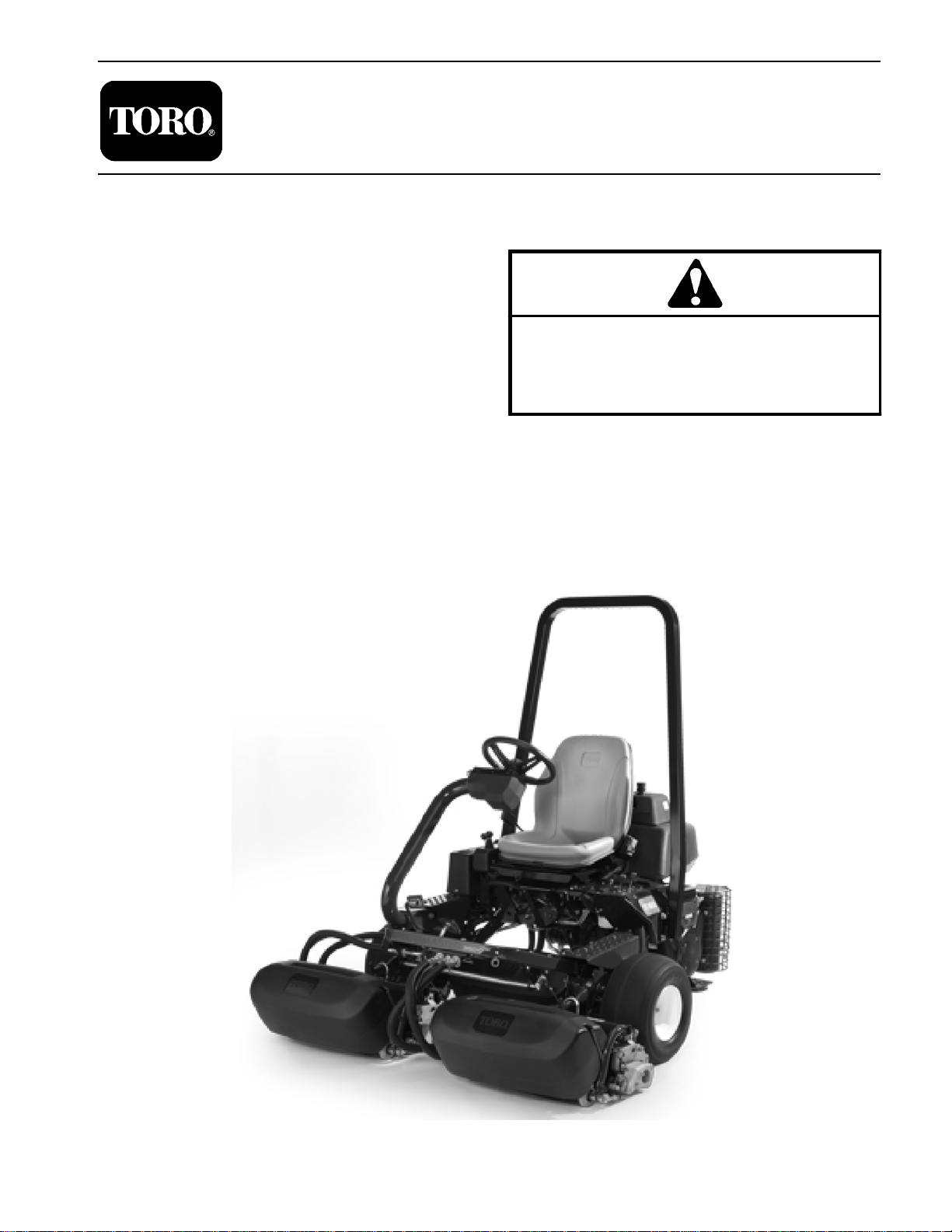
Greensmaster 3150 (Model 04358).
REFER TO THE TRACTION UNIT AND CUTTING
UNIT OPERATOR’S MANUALS FOR OPERATING,
MAINTENANCE AND ADJUSTMENT INSTRUCTIONS. For reference, insert a copy of the Operator’s
Manuals and Parts Catalogs for your machine into
Chapter 2 of this service manual. Additional copies of
theOperator’s ManualsandParts Catalogare available
on the internet at www.Toro.com.
TheT oroCompany reservesthe right tochangeproduct
specifications or this publication without notice.
Greensmaster
This safety symbol means DANGER, WARNING
or CAUTION, PERSONAL SAFETY INSTRUCTION. When you see this symbol, carefully read
the instructions that follow. Failure to obey the
instructions may result in personal injury.
NOTE: ANOTE will give general information about the
correct operation, maintenance, service, testing or repair of the machine.
IMPORTANT: The IMPORTANT notice will give importantinstructionswhichmustbefollowedtoprevent damage to systems or components on the
machine.
3150
R
E The Toro Company -- 2012
Page 2

This page is intentionally blank.
Greensmaster 3150
Page 3

Table Of Contents
Chapter 1 -- Safety
Safety Instructions 1 -- 2..........................
Jacking Instructions 1 -- 5.........................
Safety and Instruction Decals 1 -- 5................
Chapter 2 -- Product Records and Maintenance
Product Records 2 -- 1...........................
Maintenance 2 -- 1...............................
Equivalents and Conversions 2 -- 2................
Torque Specifications 2 -- 3.......................
Chapter 3 -- Engine
General Information 3 -- 2........................
Specifications 3 -- 3..............................
Service and Repairs 3 -- 4........................
BRIGGS & STRATTON VANGUARD V-TWIN OHV
REPAIR MANUAL
Chapter 4 -- Hydraulic System
Specifications 4 -- 2..............................
General Information 4 -- 3........................
Hydraulic Schematic 4 -- 8........................
Hydraulic Flow Diagrams 4 -- 10...................
Special Tools 4 -- 18.............................
Troubleshooting 4 -- 21...........................
Testing 4 - - 26...................................
Adjustments 4 -- 49..............................
Service and Repairs 4 -- 50.......................
EATON, MEDIUM DUTY PISTON PUMP , REP AIR IN-
FORMATION, MODEL 70160 VARIABLE DISPLACEMENT PISTON PUMP
PARKER TORQMOTOR
(TC, TB, TE, TJ, TF, TG, TH and TL SERIES)
SAUER/DANFOSS STEERING UNIT TYPE OSPM
SERVICE MANUAL
TM
SERVICE PROCEDURE
Chapter 5 -- Electrical System
General Information 5 -- 2........................
Special Tools 5 -- 3..............................
Turf Guardian Leak Detector
System Operation 5 -- 5........................
Troubleshooting 5 -- 6............................
Electrical System Quick Checks 5 -- 11.............
Component Testing 5 -- 12........................
Service and Repairs 5 -- 28.......................
Chapter 6 -- Chassis
Specifications 6 -- 2..............................
General Information 6 -- 3........................
Special Tools 6 -- 3..............................
Service and Repairs 6 -- 4........................
Chapter 7 -- DPA Cutting Units
Specifications 7 -- 2..............................
General Information 7 -- 3........................
Special Tools 7 -- 4..............................
Factors That Can Affect Cutting Performance 7 -- 6..
Set Up and Adjustments 7 -- 10....................
Service and Repairs 7 -- 12.......................
Chapter 8 -- Groomer
Specifications 8 -- 2..............................
General Information 8 -- 3........................
Troubleshooting 8 -- 4............................
Adjustments 8 -- 6...............................
Service and Repairs 8 -- 7........................
Chapter 9 -- Foldout Drawings
Hydraulic Schematic 9 -- 3........................
Electrical Schematic 9 -- 4........................
Electrical Circuit Diagrams 9 -- 5...................
Wire Harness Drawings 9 -- 12....................
SafetyDPA Cutting
Product Records
Engine
Hydraulic
Electrical
ChassisGroomer
and Maintenance
System
System
Units
Greensmaster 3150
Foldout
Drawings
Page 4

This page is intentionally blank.
Greensmaster 3150
Page 5

Table of Contents
SAFETY INSTRUCTIONS 2......................
Before Operating 2............................
While Operating 3............................
Maintenance and Service 4....................
JACKING INSTRUCTIONS 5.....................
SAFETY AND INSTRUCTION DECALS 5..........
Chapter 1
Safety
Safety
Greensmaster 3150 Page 1 -- 1 Safety
Page 6

Safety Instructions
The Greensmaster 3150 was tested and certified by
Toro for compliancewithnationaland international standards as specified in the Operator’s Manual. Although
hazard control and accident prevention partially are dependent upon the design and configuration of the machine, these factors are also dependent upon the
awareness, concern and proper training of the personnel involved in the operation, transport, maintenance
and storage of the machine. Improper use or maintenance of the machine can result in injury or death.
Before Operating
WARNING
Toreducethepotentialfor injury ordeath,comply
with the following safety instructions.
1. Read and understand thecontents of the Operator’s
Manual before starting and operating the machine. Become familiar with all controls and know how to stop
quickly. Copies of the Operator’s Manual are available
on the internet at www.Toro.com.
2. Never allow children to operate the machine. Never
allow adults to operate it without proper instructions.
3. Become familiar with the controls and know how to
stop the engine quickly.
4. Keep all shields, safety devices and decals in place.
Ifa shield, safety deviceordecal is defective, illegibleor
damaged: repair or replace it before operating the machine.
5. Always wear substantial shoes. Do not operate machine while wearing sandals, tennis shoes or sneakers.
Donotwearloosefittingclothingwhichcouldgetcaught
in moving parts and cause personal injury.
6. Wearing safety glasses, safety shoes, long pants
and a helmet is advisable and required by some local
safety and insurance regulations.
7. Make sure work area is clear of objects which might
be picked up and thrown by the reels.
8. Do not carry passengers on the machine. Keep everyone, especially children and pets, away from the
areas of operation.
9. Gasoline(fuel) is highly flammable; handle itcarefully.
A. Store fuel in containers specifically designed for
this purpose.
B. Add fuel before starting the engine. Never removethecapofthefueltankoraddfuelwhiletheengine is running or when the engine is hot.
C. Refuel outdoors only and do not smoke while
refuelling.
D. Fillfueltanktoalevelnohigherthantothebottom
of fuel tank filler neck. Do not overfill.
E. Replaceallfueltanksandcontainercaps securely.
F. If fuel is spilled,do notattempt tostart the engine
butmovethemachineawayfromthearea of spillage
andavoidcreatingany sourceofignitionuntilfuelvapors have dissipated.
G. Wipe up any spilled fuel.
Greensmaster 3150Page 1 -- 2Safety
Page 7

While Operating
1. Donotruntheengineinaconfinedareawithoutadequate ventilation. Exhaust fumes are hazardous and
couldbedeadly.
2. Sit on the seat when starting and operating the machine.
3. Check the safety interlockswitchdaily for properoperation; see VerifyInterlockSystem Operation in Chapter 5 -- Electrical System. Replace any malfunctioning
switches before operating the machine.
4. To start the engine:
A. Sitontheseat,makesure cutting units are disengaged.
B. Verify that functional control lever is in neutral.
C. Verify that parking brake is set.
D. Proceed to start engine.
5. Using the machine demands attention. To prevent
loss of machine control:
A. Mow only in daylight or when there is good artificial light.
B. Watch for holes or other hidden hazards.
C. Do not drive close to sand traps, ditches, creeks
or other hazards.
D. Reduce speed when making sharp turns. Avoid
sudden stops and starts.
E. Before backing up, look to the rear to be sure no
one is behind the machine.
F. Watchoutfor traffic when near orcrossingroads.
Always yield the right--of--way.
G. Apply the service brakes when going downhill to
keep forward speed slow and to maintain control of
the machine.
6. Keep hands, feet and clothing away from moving
parts and the reel discharge area. The grass baskets
must be in place during operation of the reels or thatchersformaximumsafety.Shuttheengineoffbefore emptying the baskets.
7. Wearappropriateclothingincluding substantial footwear, hard hat, safety glasses and ear protection.
8. Raise the cutting units when driving from one work
area to another.
9. Do not touch engine, muffler or exhaust pipe while
engine is running or soon after it is stopped because
these areas could be hot enough to cause burns.
10.If a cutting unit strikes a solid object or vibrates abnormally, stop immediately, turn engine off, wait for all
motionto stop and inspect for damage.A damaged reel
or bedknife must be repaired or replaced before operation is continued.
11.Before getting off the seat:
A. Make sure cutting units are disengaged.
B. Verify that functional control lever is in neutral.
C. Set the parking brake.
D. Stop the engine and remove key from ignition
switch.
12.Traverse slopes carefully. Do not start or stop sud-
denly when traveling uphill or downhill.
13.Operator must be skilled and trained in how to drive
on hillsides. Avoid wet slopes. Failure to use caution on
slopes or hills may cause loss of control and vehicle to
tip or roll possibly resulting in personal injury or death.
14.If engine stalls or loses headway and cannot make
it to the top of a slope, do not turn machine around. Always back slowly straight down the slope.
15.DON’T TAKE AN INJURY RISK! Whenapersonor
pet appears unexpectedly in or near the mowing area,
STOP MOWING. Careless operation, combined with
terrain angles, ricochets or improperly positioned
guardscanlead to thrownobjectinjuries.Donotresume
mowing until area is cleared.
16.Whenever machine is left unattended, make sure
cutting units are fully raised and reels are not spinning,
key is removed from ignition switch and parking brake
is set.
Safety
Greensmaster 3150 Page 1 -- 3 Safety
Page 8

Maintenance and Service
1. Before servicing or making adjustments to the machine, stop the engine, remove key from switch to prevent accidental starting of the engine.
2. Be sure entire machine is in good operating condition. Keep all nuts, bolts, screws and hydraulic fittings
tight.
3. Make sure allhydraulic line connectorsare tight,and
all hydraulic hoses and lines are in good condition before applying pressure to the system.
4. Keep body and hands away from pin hole leaks or
nozzles that eject hydraulic fluid under high pressure.
Use paper or cardboard, not hands, to search for leaks.
Hydraulic fluid escaping under pressure can have sufficient force to penetrate skin and do serious damage. If
fluidisejectedintotheskinitmustbesurgically removed
within a few hours by a doctor familiar with this form of
injury or gangrene may result.
5. Before disconnecting or performing any work on the
hydraulic system, all pressure in system must be relievedbystoppingengineandloweringcuttingunitsand
attachments to the ground.
6. Toreducepotential fire hazard, keeptheenginearea
free of excessive grease, grass, leaves and accumulation of dirt.Never wash a warm engineor electrical connections with water.
7. Check all fuel linesfor tightness andwear on aregular basis. Tighten or repair fuel lines as needed.
9. Do not overspeed the engine by changing governor
settings.Toassuresafetyandaccuracy,have an Authorized Toro Distributor check maximum engine speed
with a tachometer. Maximum governed engine speed
should be 2850 +
10.Enginemustbeshutoffbeforechecking oiloradding
oil to the crankcase.
11.If major repairs are ever needed or if assistance is
desired, contact your Authorized Toro Distributor.
12.At the time of manufacture, the machine conformed
tothe safety standards for ridingmowers. To assure optimumperformanceandcontinuedsafetycertificationof
the machine, use genuine Toro replacement parts and
accessories.Replacementpartsandaccessoriesmade
by other manufacturers may result in non-conformance
with the safety standards and the warranty may be
voided.
13.When changing attachments, tires or performing
other service, use correct blocks, hoists and jacks.
Make sure machine is parkedonasolidlevelsurface
suchasaconcretefloor.Priortoraisingthemachine,remove any attachments that may interfere with the safe
and proper raising of the machine. Always chock or
block wheels. Use appropriate jack stands to support
the raised machine. If the machine is not properly supported by jack stands, the machine may move or fall,
which may result in personal injury.
50 RPM.
8. If the engine must be running to perform a maintenance adjustment, keep hands, feet, clothing and any
other parts of the body away from the cutting units, attachmentsandany moving parts.Keep everyone away.
Greensmaster 3150Page 1 -- 4Safety
Page 9
Jacking Instructions
CAUTION
When changing attachments, tires or performing other service, use correct jacks and supports. Make sure machine is parked on a solid,
level surface such as a concrete floor. Prior to
raising machine, remove any attachments that
may interfere with the safe and proper raising of
themachine.Always chockorblockwheels.Use
jack stands to supportthe raised machine. If the
machine is not properly supported by jack
stands, the machine may move or fall, which
may result in personal injury.
Front End Jacking
1. Apply parking brake and chock rear tire to prevent
the machine from moving. Make sure that cutting units
are fully lowered.
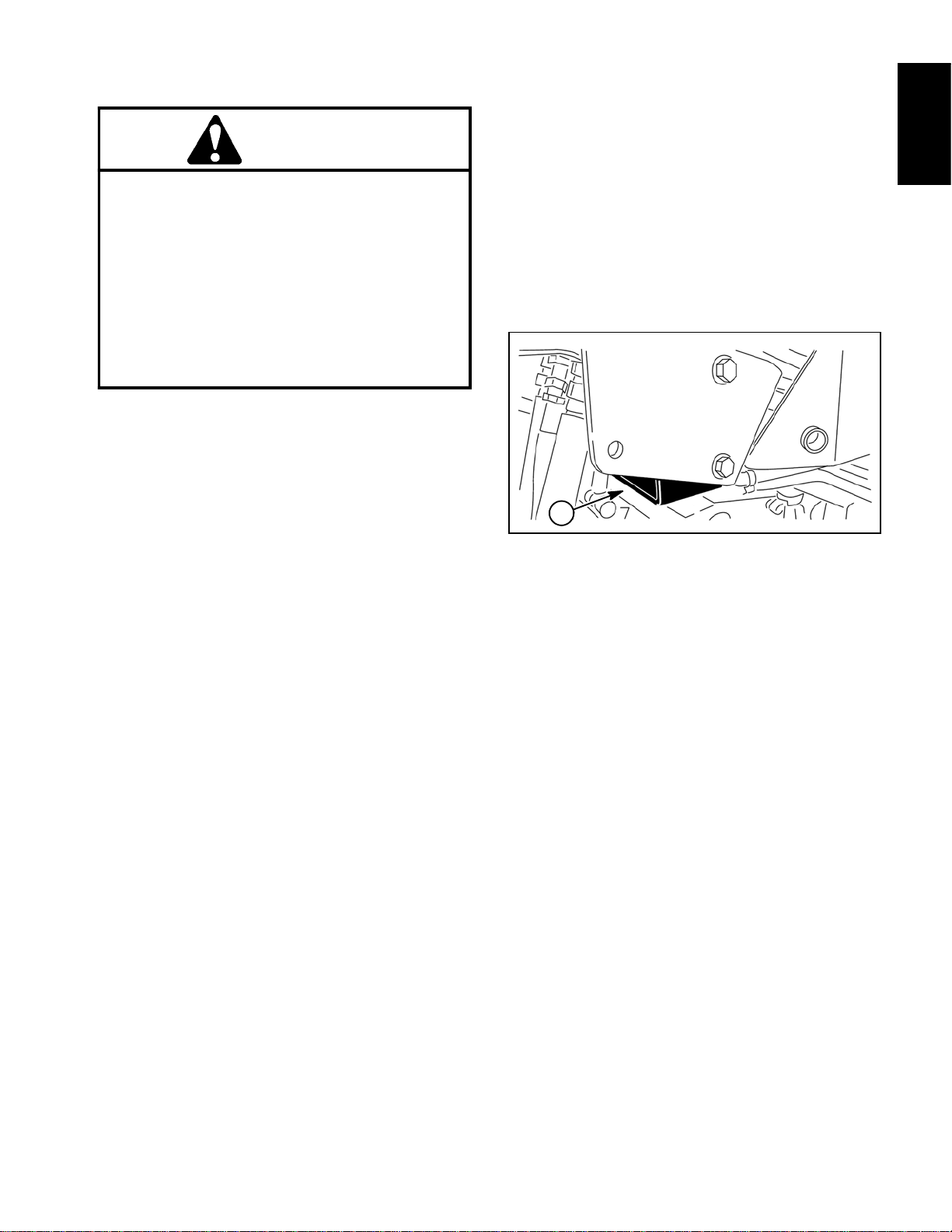
2. Position jack securelyunder the framejacking point:
Rear End Jacking
1. Applyparkingbrakeandchock both front tirestopre-
vent the machine from moving. Make sure that cutting
units are fully lowered.
2. Place jack securely below the rear castor fork.
3. Jack rear of machine off the ground.
4. Position appropriate jack stands under the frame to
support the machine.
1
Safety
A. The left side jacking point is the frame channel
under the step behind the LH front wheel.
B. The right side jacking point is the ROPS support
bracket behind the RH front wheel (Fig. 1).
3. Jack front of machine off the ground.
4. Position appropriate jack stands under the frame as
close to the wheel as possible to support the machine.
Safety and Instruction Decals
Numerous safety and instruction decals are affixed to
the traction unit and the cutting units of the Greensmaster 3150. If any decal becomes illegible or damaged, install a new decal. Part numbers are listed in your Parts
CatalogandOperator’s Manual. Order replacement decals from your Authorized Toro Distributor.
Figure 1
1. ROPS support bracket
Greensmaster 3150 Page 1 -- 5 Safety
Page 10

This page is intentionally blank.
Greensmaster 3150Page 1 -- 6Safety
Page 11

Product Records and Maintenance
Table of Contents
PRODUCT RECORDS 1.........................
MAINTENANCE 1..............................
EQUIVALENTS AND CONVERSIONS 2...........
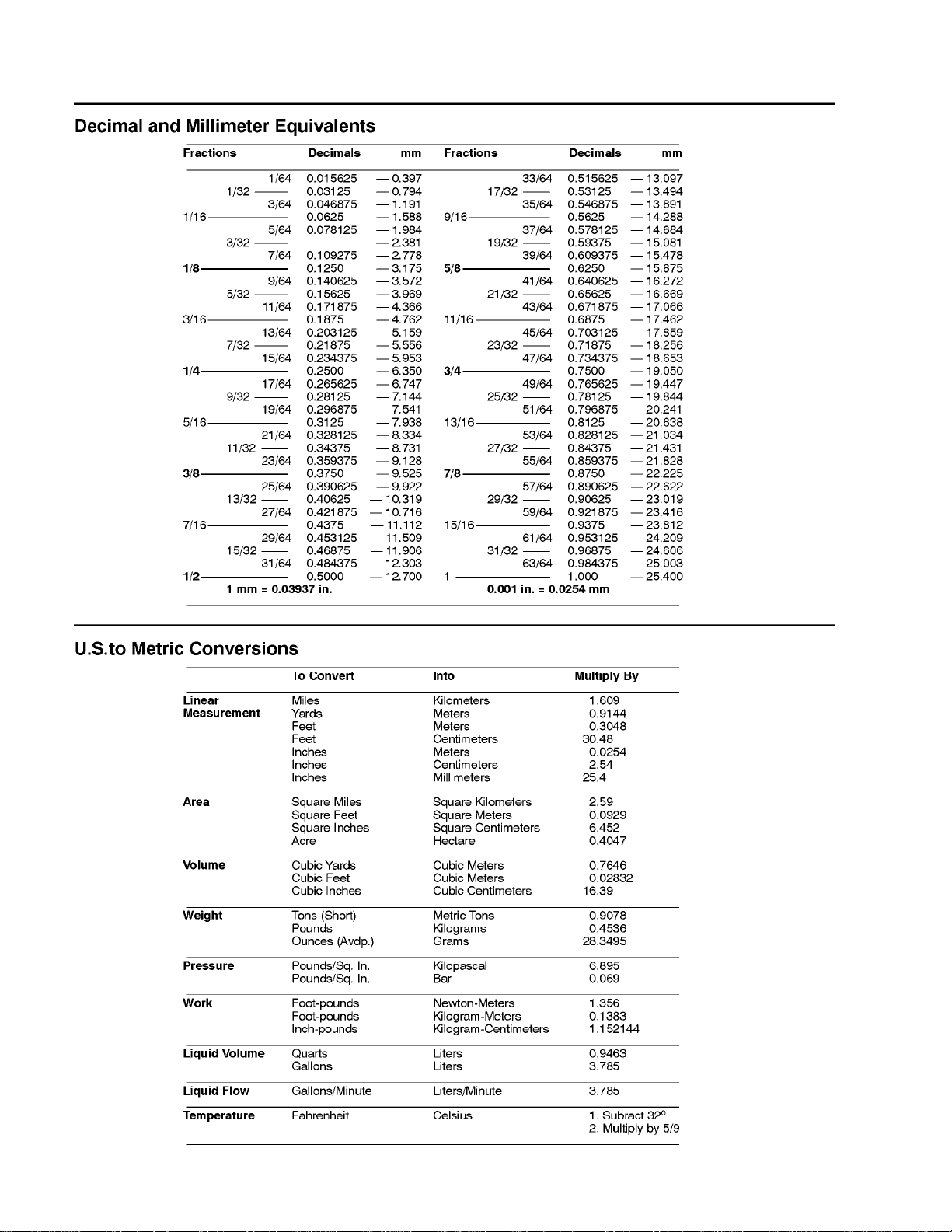
Decimal and Millimeter Equivalents 2............
U.S. to Metric Conversions 2...................
TORQUE SPECIFICATIONS 3...................
Fastener Identification 3.......................
Using a Torque Wrench with an Offset Wrench 3..
Standard Torque for Dry, Zinc Plated and
Steel Fasteners (Inch Series). 4...............
Standard Torque for Dry, Zinc Plated and
Steel Fasteners (Metric Fasteners). 5..........
Other Torque Specifications 6..................
Conversion Factors 6.........................
Chapter 2
Product Records
and Maintenance
Product Records
Insert a copy of the Operator’s Manual and Parts Catalog for your Greensmaster 3150 at the end of this chapter. Additionally, if any optional equipment or
accessorieshavebeen installed to yourmachine, insert
the Installation Instructions, Operator’s Manuals and
PartsCatalogs for thoseoptions at theend of thischapter.
Maintenance
Maintenanceproceduresandrecommendedserviceintervals for the Greensmaster 3150 are covered in the
Traction Unit Operator’s Manual. Maintenance procedures and recommended service intervals for the
Greensmaster Cutting Units are covered in the Cutting
Unit Operator’s Manual. Refer to these publications
when performing regular equipment maintenance. Refer to the Engine Operator’s Manual for additional engine specific maintenance procedures.
Greensmaster 3150 Page 2 -- 1 Product Records and Maintenance
Page 12
Equivalents and Conversions
0.09375
Greensmaster 3150Page 2 -- 2Product Records and Maintenance
Page 13
Torque Specifications
Recommended fastener torque values are listed in the
following tables. For critical applications, as determined
byToro,eithertherecommendedtorque or atorquethat
is unique to the application is clearly identified and specified in this Service Manual.
Thesetorquespecificationsfortheinstallationandtightening of fasteners shall apply to all fasteners which do
nothave a specific requirement identifiedinthis Service
Manual.The following factors shall beconsideredwhen
applying t orque: cleanliness of the fastener, use of a
threadsealant(e.g.L octite), degree oflubricationonthe
fastener,presence of a prevailing torque feature, hardness of the surface underneath the fastener’s head or
similar condition which affects the installation.
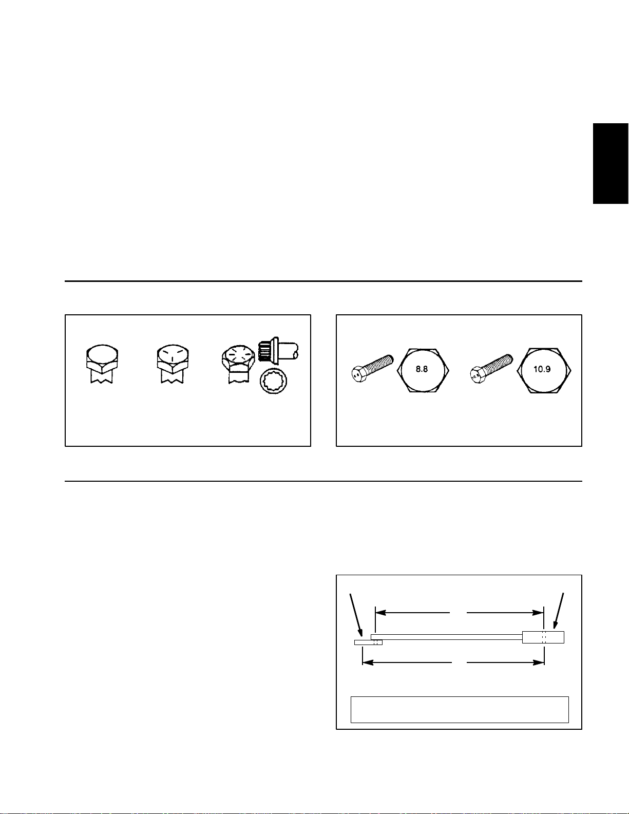
Fastener Identification
Asnotedinthefollowingtables, torque valuesshouldbe
reduced by 25% for lubricated fasteners to achieve
the similar stress as a dry fastener. Torque values may
also have to be reduced when the fastener is threaded
into aluminum or brass. The specific torque value
should be determined based on the aluminum or brass
material strength, fastener size, length of thread engagement, etc.
The standard method of verifying torque shall be performed by marking a line on the fastener (head or nut)
and mating part, then back off fastener 1/4 of a turn.
Measurethetorque required to tightenthefasteneruntil
thelinesmatchup.
Product Records
and Maintenance
Grade 1 Grade 5 Grade 8
Inch Series Bolts and Screws
Figure 1
Using a Torque Wrench with an Offset Wrench
Useofanoffsetwrench(e.g.crowfootwrench)willaffect
torquewrench calibration dueto theeffectivechange of
torque wrench length. When usinga torque wrenchwith
an offset wrench, multiply the listed torque recommendation by the calculated torque conversion factor (Fig.
3) to determine proper tightening torque. Tightening
torque when using a torque wrench with an offset
wrench will be lower than the listed torque recommendation.
Example: The measured effective length of the torque
wrench (distance from the center of the handle to the
center of the square drive) is 18”.
Themeasuredeffectivelengthofthetorquewrenchwith
the offset wrench installed (distance from the center of
the handle to the center of the offset wrench) is 19”.
Class 8.8 Class 10.9
Metric Bolts and Screws
Figure 2
If the listed torque recommendation for a fastener is
from 76 to 94 ft--lb, the proper torque when using this
torque wrench with an offset wrench would be from 72
to 89 ft--lb.
(effective length of
torque wrench)
A
B
(effective length of torque
wrench + offset wrench)
TORQUE CONVERSION FACTOR = A / B
T orque wrenchOffset wrench
The calculated t orque conversion factor for this torque
wrenchwith this offsetwrench would be18 / 19 = 0.947.
Greensmaster 3150 Page 2 -- 3 Product Records and Maintenance
Figure 3
Page 14

Standard Torque for Dry, Zinc Plated and Steel Fasteners (Inch Series)
Grade1,5,&
Thread Size
#6--32UNC
#6--40UNF 17 + 2 190 + 20 25 + 2 280 + 20
#8--32UNC
#8--36UNF 31 + 3 350 + 30 43 + 4 485 + 45
#10--24UNC
#10--32UNF 48 + 4 540 + 45 68 + 6 765 + 70
1/4 -- 20 UNC 48 + 7 53 + 7 599 + 79 100 + 10 1125+ 100 140 + 15 1580+ 170
1/4 -- 28 UNF 53 + 7 65 + 10 734 + 113 115 + 10 1300 + 100 160 + 15 1800 + 170
5/16 -- 18 UNC 115 + 15 105 + 17 1186 + 169 200 + 25 2250 + 280 300 + 30 3390 + 340
5/16 -- 24 UNF 138 + 17 128 + 17 1446 + 192 225 + 25 2540+ 280 325 + 30 3670 + 340
3/8 -- 16 UNC 16 + 2 16 + 2 22 + 3 30 + 3 41 + 4 43 + 4 58 + 5
8withThin
Height Nuts
in--lb in--lb N--cm in--lb N--cm in--lb N--cm
10 + 2 13 + 2 147 + 23
13 + 2 25 + 5 282 + 30
18 + 2 30 + 5 339 + 56
ft--lb ft--lb N--m ft--lb N--m ft--lb N--m
SAE Grade 1 Bolts, Screws, Studs, &
Sems with Regular Height Nuts
(SAE J995 Grade 2 or Stronger Nuts)
SAE Grade 5 Bolts, Screws, Studs, &
Sems with Regular Height Nuts
(SAE J995 Grade 2 or Stronger Nuts)
15 + 2 170 + 20 23 + 2 260 + 20
29 + 3 330 + 30 41 + 4 460 + 45
42 + 4 475 + 45 60 + 6 675 + 70
SAE Grade 8 Bolts, Screws, Studs, &
Sems with Regular Height Nuts
(SAE J995 Grade 5 or Stronger Nuts)
3/8 -- 24 UNF 17 + 2 18 + 2 24 + 3 35 + 3 47 + 4 50 + 4 68 + 5
7/16 -- 14 UNC 27 + 3 27 + 3 37 + 4 50 + 5 68 + 7 70 + 7 95 + 9
7/16 -- 20 UNF 29 + 3 29 + 3 39 + 4 55 + 5 75 + 7 77 + 7 104 + 9
1/2 -- 13 UNC 30 + 3 48 + 7 65 + 9 75 + 8 102 + 11 105 + 10 142 + 14
1/2 -- 20 UNF 32 + 3 53 + 7 72 + 9 85 + 8 115 + 11 120 + 10 163 + 14
5/8 -- 11 UNC 65 + 10 88 + 12 119 + 16 150 + 15 203 + 20 210 + 20 285 + 27
5/8 -- 18 UNF 75 + 10 95 + 15 129 + 20 170 + 15 230 + 20 240 + 20 325 + 27
3/4 -- 10 UNC 93 + 12 140 + 20 190 + 27 265 + 25 359 + 34 375 + 35 508 + 47
3/4 -- 16 UNF 115 + 15 165 + 25 224 + 34 300 + 25 407 + 34 420 + 35 569 + 47
7/8 -- 9 UNC 140 + 20 225 + 25 305 + 34 430 + 45 583 + 61 600 + 60 813 + 81
7/8 -- 14 UNF 155 + 25 260 + 30 353 + 41 475 + 45 644 + 61 660 + 60 895 + 81
NOTE: Reduce torque values listed in the table above
by 25% for lubricated fasteners. Lubricated fasteners
are defined as threads coated with a lubricant such a s
oil, graphite or thread sealant such as Loctite.
NOTE: The nominal torque values listed above for
Grade 5 and 8 fasteners are based on 75% of the minimum proof load specified in SAEJ429. The tolerance is
approximately +
10% of t he nominal torque value. Thin
height nuts include jam nuts.
NOTE: Torque values may have to be reduced when
installing fasteners into threaded aluminum or brass.
The specific torque value should be determined based
on the fastener size, the aluminum or base material
strength, length of thread engagement, etc.
Greensmaster 3150Page 2 -- 4Product Records and Maintenance
Page 15
Standard Torque for Dry, Zinc Plated and Steel Fasteners (Metric Fasteners)
Class 8.8 Bolts, Screws and Studs with
Thread Size
M5 X 0.8 57 + 5in--lb 640 + 60 N--cm 78 + 7in--lb 885 + 80 N--cm
M6 X 1.0 96 + 9in--lb 1018 + 100 N--cm 133 + 13 in--lb 1500 + 150 N--cm
M8 X 1.25 19 + 2ft--lb 26 + 3N--m 27 + 2ft--lb 36 + 3N--m
M10 X 1.5 38 + 4ft--lb 52 + 5N--m 53 + 5ft--lb 72 + 7N--m
M12 X 1.75 66 + 7ft--lb 90 + 10 N--m 92 + 9ft--lb 125 + 12 N--m
M16 X 2.0 166+ 15 ft--lb 225 + 20 N--m 229 + 22 ft--lb 310 + 30 N--m
M20 X 2.5 325 + 33 ft--lb 440 + 45 N--m 450 + 37 ft--lb 610 + 50 N--m
NOTE: Reduce torque values listed in the table above
by 25% for lubricated fasteners. Lubricated fasteners
are defined as threads coated with a lubricant such as
oil, graphite or thread sealant such as Loctite.
NOTE: Torque values may have to be reduced when
installing fasteners into threaded aluminum or brass.
The specific torque value should be determined based
on the fastener size, the aluminum or base material
strength, length of thread engagement, etc.
Regular Height Nuts
(Class 8 or Stronger Nuts)
NOTE: The nominal torque values listed above are
based on 75% of the minimum proof load specified in
SAEJ1199.Thetoleranceisapproximately+
nominal torque value.
Class 10.9 Bolts, Screws and Studs with
Regular Height Nuts
(Class 10 or Stronger Nuts)
10%ofthe
Product Records
and Maintenance
Greensmaster 3150 Page 2 -- 5 Product Records and Maintenance
Page 16
Other Torque Specifications
SAE Grade 8 Steel Set Screws
Recommended Torque
Thread Size
Square Head Hex Socket
1/4 -- 20 UNC 140 + 20 in--lb 73 + 12 in--lb
5/16 -- 18 UNC 215 + 35 in--lb 145 + 20 in--lb
3/8 -- 16 UNC 35 + 10 ft--lb 18 + 3ft--lb
1/2 -- 13 UNC 75 + 15 ft--lb 50 + 10 ft--lb
Thread Cutting Screws
(Zinc Plated Steel)
Type 1, Type 23 or Type F
Thread Size Baseline Torque*
No. 6 -- 32 UNC 20 + 5in--lb
Wheel Bolts and Lug Nuts
Thread Size
7/16 -- 20 UNF
Grade 5
1/2 -- 20 UNF
Grade 5
M12 X 1.25
Class 8.8
M12 X 1.5
Class 8.8
* For steel wheels and non--lubricated fasteners.
Thread Cutting Screws
(Zinc Plated Steel)
Thread
Size
No. 6 18 20 20 + 5in--lb
Threads per Inch
Type A Type B
Recommended Torque*
65 + 10 ft--lb 88 + 14 N--m
80 + 10 ft--lb 108 + 14 N--m
80 + 10 ft--lb 108 + 14 N--m
80 + 10 ft--lb 108 + 14 N--m
Baseline Torque**
No. 8 -- 32 UNC 30 + 5in--lb
No. 10 -- 24 UNC 38 + 7in--lb
1/4 -- 20 UNC 85 + 15 in--lb
5/16 -- 18 UNC 110 + 20 in--lb
3/8 -- 16 UNC 200 + 100 in--lb
Conversion Factors
in--lb X 11.2985 = N--cm N--cm X 0.08851 = in--lb
ft--lb X 1.3558 = N--m N--m X 0.7376 = ft--lb
No. 8 15 18 30 + 5in--lb
No. 10 12 16 38 + 7in--lb
No. 12 11 14 85 + 15 in--lb
** Hole size, material strength, material thickness & finish must be considered when determining specific
torquevalues.Alltorquevaluesarebasedonnon--lubricated fasteners.
Greensmaster 3150Page 2 -- 6Product Records and Maintenance
Page 17

Table of Contents
GENERAL INFORMATION 2.....................
Operator’s Manual 2..........................
SPECIFICATIONS 3............................
SERVICE AND REPAIRS 4......................
Fuel Tank 4..................................
Engine 6.....................................
Engine Removal 7...........................
Engine Installation 7.........................
Fuel Evaporative Control System 10.............
BRIGGS&STRATTONVANGUARDV--TWIN OHVRE-
PAIR MANUAL
Chapter 3
Engine
Engine
Greensmaster 3150 Page 3 -- 1 Engine
Page 18

General Information
This Chapter gives information about specifications,
maintenance, troubleshooting, testing and repair of the
engine used in the Greensmaster 3150.
Most repairs and adjustments require tools which are
commonly available in many service shops. Special
tools are described in the Briggs & Stratton Vanguard
V-Twin OHV Repair Manual. The use of some specialized test equipment is explained. However, the cost of
the test equipment and the specialized nature of some
repairs may dictate that the work be done at an engine
repair facility.
Operator’s Manual
The TractionUnit Operator’s Manual provides information regarding the operation, general maintenance and
maintenanceintervalsfor your Greensmaster 3150 machine. Refer to the Operator’s Manual for additional information when servicing the machine.
Service and repair parts for Briggs& Stratton Vanguard
V-Twin OHV engines are suppliedthrough your locallocalTorodistributor.Ifno parts list is available, be sure to
provide your distributor with the Toro model and serial
numberalongwith the enginemodeland serial number.
Greensmaster 3150Page 3 -- 2Engine
Page 19

Specifications
Item Description
Make / Designation Briggs and Stratton, 4--cycle, V--Twin Cylinder,
OHV, Air Cooled, Gasoline Engine -- Model 356447
Bore x Stroke 2.83” x 2.76” (72 mm x 70 mm)
Total Displacement 34.8 in3(570 cc)
Governor Mechanical Governor
Carburetor Float Feed
Fuel Pump Pulsating Crankcase Vacuum
Fuel Unleaded, regular grade gasoline
Fuel TankCapacity 7.0 U.S. gallons (26.5 liters)
Low Idle (no load) 1650 + 100 RPM
High Idle (no load) 2850 + 50 RPM
Lubrication System Pressure Lubrication, Gear Driven Geroter Oil Pump
Engine Oil See Operator’s Manual
Crankcase Oil Capacity 1.75 U.S. quarts (1.65 liters) with new filter
Engine
Ignition System Flywheel magneto, twin electronic armatures
Spark Plugs Champion RC 14YC (or equivalent)
Spark Plug Gap 0.030” (0.76 mm)
Alternator 16 Amp
Dry Weight (approximate) 84 lb (38 kg)
Greensmaster 3150 Page 3 -- 3 Engine
Page 20
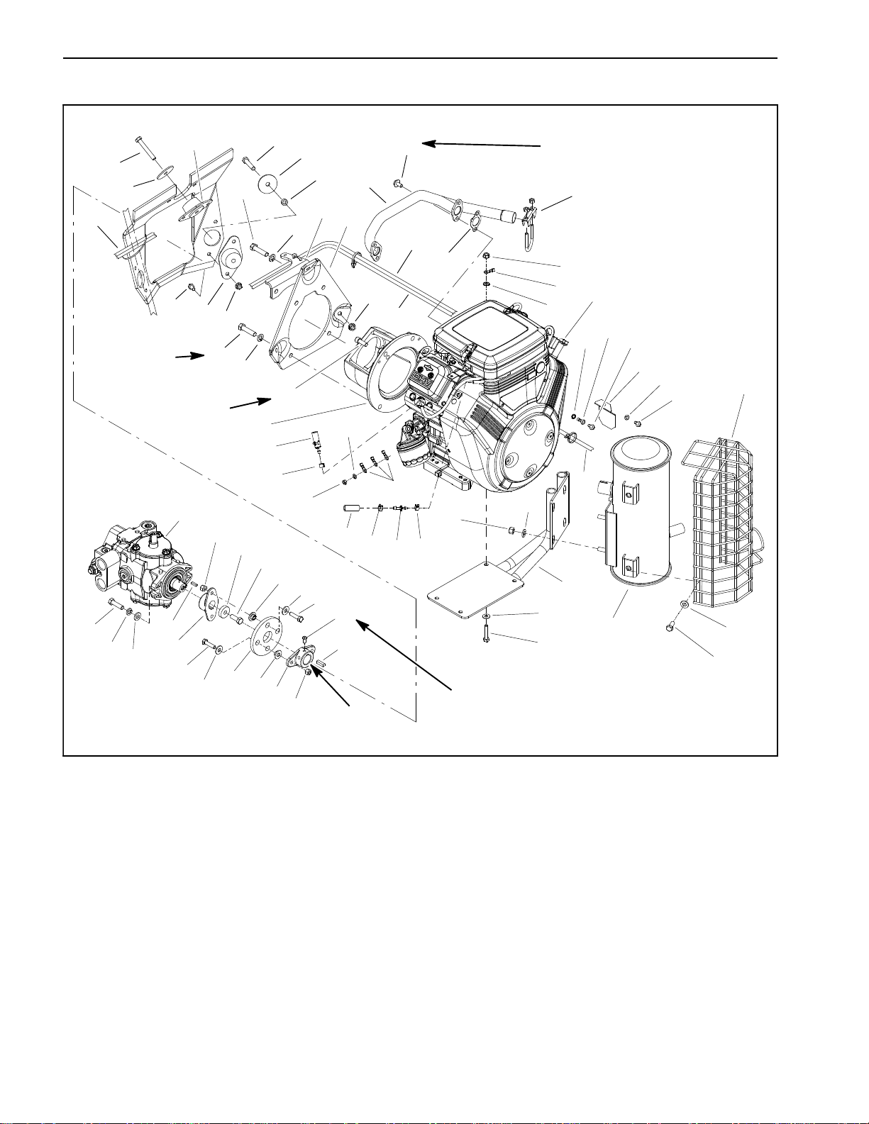
Service and Repairs
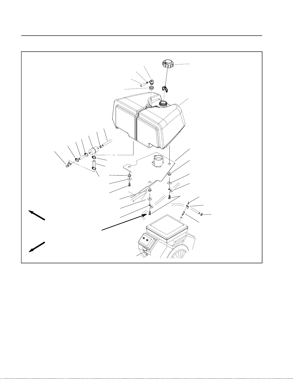
Fuel Tank
15
RIGHT
FRONT
1
2
14
2
Antiseize
Lubricant
30 to 60 in--lb
(3.4 to 6.7 N--m)
18
16
13
4
20
21
22
5
3
12
16
6
17
6
7
9
7
8
9
10
6
11
7
18
8
19
1. Fuel filter
2. Hose clamp
3. Fuel hose (filter to engine)
4. Fuel cap
5. Fuel tank
6. Grommet (4 used)
7. Flat washer (4 used)
8. Hose support clamp
Figure 1
9. Cap screw (4 used)
10. Cap screw
11. Hose support clamp
12. Vehicle frame
13. Fuel tank vent fitting
14. Fuel hose (shut--off valve to filter)
15. Fuelshut--off valve
16. Hose clamp
17. Fuel hose (tank to shut--off valve)
18. Hose clamp
19. Spacer
20. Hose clamp
21. Fuel vent hose (fitting to cannister)
22. Grommet
Greensmaster 3150Page 3 -- 4Engine
Page 21
Fuel Tank Removal (Fig. 1)
Fuel Tank installation (Fig. 1)
1. Park machine on a level surface, lower cutting units,
stop the engine, engage parking brake and remove the
key from the ignition switch.
CAUTION
The muffler and exhaust manifold may be hot.
Avoid possible burns, allow exhaust system to
cool before working on the engine.
DANGER
Gasolineisflammable.Use caution whenstoring
or handling it. Do not smoke while filling the fuel
tank. Do not fill fuel tank while engine is running
or in an enclosed area. Always fill fuel tank outside and wipe up any spilled fuel before starting
the engine. Store fuel in a clean, safety--approved container and keep the cap in place. Use
gasoline for the engine only; not for any other
purpose.
IMPORTANT: After fuel tank is installed, make sure
that clearance between hydraulic reservoir and fuel
tank if from 0.125” to 0.375” (3.2 to 9.5 mm).
1. Position fuel tank on the vehicle frame.
A. Applyantiseizelubricantto the threads ofthefour
(4) cap screws (item 9).
B. Securethe fuel tanktothe vehicle framewith four
(4) flat washers (item 7), grommets (item 6) and cap
screws (item 9). Make sure the grommets are
between the flat washers and the frame. Also, make
sure that fuelhose support clamps (item 8) are positioned correctly.
C. Torquecapscrewsfrom30to60in--lb(3.4 to6.7
N--m).
2. Connect vent hose (item 21) to fuel tank vent fitting
(item 13) on top of tank and secure with hose clamp.
Make sure that hose is not kinked or obstructed.
3. Connectfuelhose (item 14) to thefuelshut--off valve
(item15)andsecurewithhoseclamp.
Engine
2. Drain fuel tank as follows:
A. Close fuel shut--off valve (item 15).
B. Disconnectfuelhose(item14) atthe fuelshut--off
valve and drain any fuel trapped in the fuel filter and
fuel hose into a suitable container.
C. Installoneendofasparelengthoffuelhoseto the
fuel shut--off valve and place the other end of the
hose into a suitable container for draining the tank.
D. Drain fuel tank completely by opening the fuel
shut off valve.
E. Remove the spare length of fuel hose from the
fuel shut--off valve.
3. Disconnectventhose(item21)fromfueltankventfit-
ting (item 13) on top of tank.
4. Remove four (4) cap screws (item 9), grommets
(item 6) and flat washers (item 7) securing the fuel tank
to the vehicle frame. Remove the fuel tank from the vehicle frame.
4. Open fuel shut--off valve and fill fuel tank with fuel.
Check all fuel hoses and tank for leaks.
Greensmaster 3150 Page 3 -- 5 Engine
Page 22
Engine
1
2
29
25 to 38 ft--lb
(34to51N--m)
18 to 23 ft--lb
(25to31N--m)
53
52
51
56
54
25
46
55
24
45
24
23
42
16
44
39
22
50
43
19
33
49
34
41
1
20
43
22
38
42
2
3
40
45
46
Antiseize
Lubricant
27
37
47
48
21
30
170 to 200 in--lb
(20 to 22 N--m)
4
6
29
31
7
32
17
11
16
27
8
11
28
5
27
10
28
11
12
29
26
36
35
34
13
15
9
12
14
18
Loctite #242
90 to 110 in--lb
(10.2 to 12.4 N--m)
1. Cap screw (3 used)
2. Flat washer (3 used)
3. Spacer (3 used)
4. Exhaust manifold
5. Regulator shield
6. Muffler clamp
7. Flange nut (3 used)
8. Engine assembly
9. Muffler
10. Muffler shield
11. Ground wires
12. Flat washer (8 used)
13. Muffler mount
14. Cap screw (4 used)
15. Flat washer (4 used)
16. Hex flange nut (10 used)
17. Lock washer
18. Cap screw (4 used)
19. Pump adapter
Figure 2
20. Socket head screw (2 used)
21. Engine mount plate
22. Lock washer (4 used)
23. Cap screw (2 used)
24. Engine mount (3 used)
25. Cap screw (6 used)
26. Lock nut (4 used)
27. Spring washer (3 used)
28. Washer head screw (2 used)
29. Engine wire harness
30. Flange head screw (4 used)
31. Gasket (2 used)
32. Battery cable
33. Purge hose assy (to intake manifold)
34. Hose clamp (2 used)
35. Barbed fitting
36. Hose clamp
37. Hose (to air cleaner base)
38. Hex nut
39. Cap screw (2 used)
40. Spring bracket
41. Engine hub
42. Lock nut (4 used)
43. Coupling spacer (4 used)
44. Rubber coupling
45. Flat washer (4 used)
46. Cap screw (4 used)
47. Square head set screw (2 used)
48. Key
49. Cap screw
50. Spacer
51. Hardened washer (2 used)
52. Lock washer (2 used)
53. Cap screw (2 used)
54. Pump hub
55. Piston pump assembly
56. Key
Greensmaster 3150Page 3 -- 6Engine
Page 23
Engine Removal (Fig. 2)
1. Park machine on a level surface, lower cutting units,
stop engine, engage parking brake and remove key
from the ignition switch.
11.Carefully move the engine away from the piston
pump until the crankshaft clears the engine hub. Remove the engine from the machine. Locate and retrieve
key (item 48) from crankshaft.
2. Disconnect negative (--) battery cable from battery.
CAUTION
The muffler and exhaust manifold may be hot.
Avoid possible burns, allow exhaust system to
cool before working on the engine.
DANGER
Gasolineisflammable.Use caution whenstoring
or handling it. Do not smoke while filling the fuel
tank. Do not fill fuel tank while engine is running
or in an enclosed area. Always fill fuel tank outside and wipe up any spilled fuel before starting
the engine. Store fuel in a clean, safety--approved container and keep the cap in place. Use
gasoline for the engine only; not for any other
purpose.
3. Close fuel shut--off valve on fuel tank.
1
1. Engine assembly
2. Fuel supply hose
3. Cap screw
4. Support clamp
25 to 38 ft--lb
(34to51N--m)
2
Figure 3
3
6
7
5. Hose clamp
6. Spacer screw
7. Washer
4
3
4
5
Engine
2
4. Removethefuelhosesupportclampanddisconnect
fuelhoseatthefuelpump(Fig.3).Drainany fueltrapped
in the fuel filter and fuel hose into a suitable container.
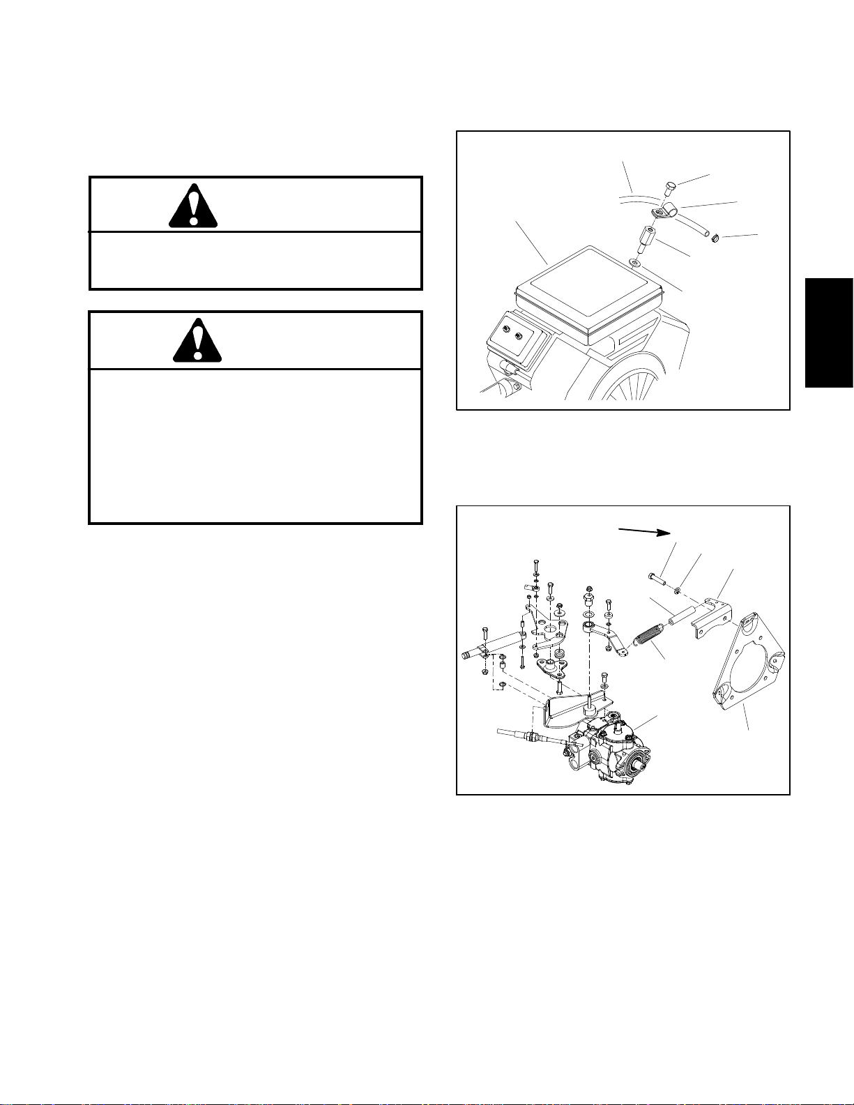
5. Disconnect the fuel evaporative control system
hoses from engine (see Fuel Evaporative Control System in this section).
6. Disconnect the engine wiring harness (item 29), the
choke control cable, the throttle control cable and the
ground wires (item 11) at the engine.
7. Carefully disconnect extension spring on piston
pump control assembly from spring bracket that is a ttached to engine mount plate (Fig. 4).
8. Loosen the two(2) set screws(item 47) securing the
engine hub (item 41) to the engine shaft.
9. Support the piston pump assembly and remove the
two(2)capscrews(item 53), lockwashers(item52)and
hardened washers (item 51) securing the pump to the
pumpadapter (item 19). Do Not disconnectthe hydraulic hoses or neutral control linkage from the pump.
10.Support the engine assembly and remove the three
(3) engine mount flange nuts (item 7), cap screws (item
1), flat washers (item 2) and spacers (item 3).
5
6
7
1
Figure 4
1. Engine mount plate
2. Spring bracket
3. Lock washer (2 used)
4. Cap screw (2 used)
5. Dampener hose
6. Extension spring
7. Piston pump assembly
Engine Installation (Fig. 2)
1. Make sure that all parts removed from the engine
duringmaintenanceorrebuildingareinstalledto the engine.
2. Apply antiseize lubricant to bore of engine hub.
Place key (item 48) into slot on the engine crankshaft.
Greensmaster 3150 Page 3 -- 7 Engine
Page 24

IMPORTANT: Make sure to not damage engine, fuel
hose, hydraulic hoses, electrical harness, control
cables or other parts while installing the engine.
Makesureenginehubisinpositionbeforeinstalling
the engine mount cap screws.
3. Align the engine hub (item 41) with the engine shaft
and key (item 48). Slide crankshaft into hub and move
engine until the engine mount plate (item 21) is aligned
with the three (3) engine mounts (item 24). Takecare to
notdamage therubber coupling(item 44) duringengine
installation.
4. Install the three (3) engine mount cap screws (item
1), flat washers (item 2), spacers (item 3) and flange
nuts (item 7).
8. Carefully connect extension spring on piston pump
controlassemblytospringbracket thatisattachedtoengine mount plate (Fig. 4).
9. Connect the engine wiring harness (item 29) and
ground wires (item 11) to the engine.
10.Connect and adjust the choke and throttle control
cables.
11.Connect the f uel evaporative control system hoses
to engine (see Fuel Evaporative Control System in this
section).
12.Connect fuel hose to the fuel pump and secure with
hose clamp. Install the fuel hose support clamp.
5. Position the piston pump assembly to the pump
adapter (item 19) and secure with two (2) cap screws
(item53)lock washers (item 52)andhardenedwashers
(item 51).
6. Position engine hub on crankshaft to best align the
rubber coupling.
7. Apply Loctite #242 (or equivalent) to threads of enginehubset screws (item 47).Securehub to crankshaft
with two (2) set screws. Torque set screws from 90 to
110 in--lb (10.2 to 12.4N--m).
13.Secure negative (--) battery cable to battery.
14.Open fuel shut--off valve on fuel tank. Check fuel
hose for leaks.
15.Check engine oil level and adjust if necessary.
16.Start the engine and check for proper engine operation.
Greensmaster 3150Page 3 -- 8Engine
Page 25

This page is intentionally blank.
Engine
Greensmaster 3150 Page 3 -- 9 Engine
Page 26
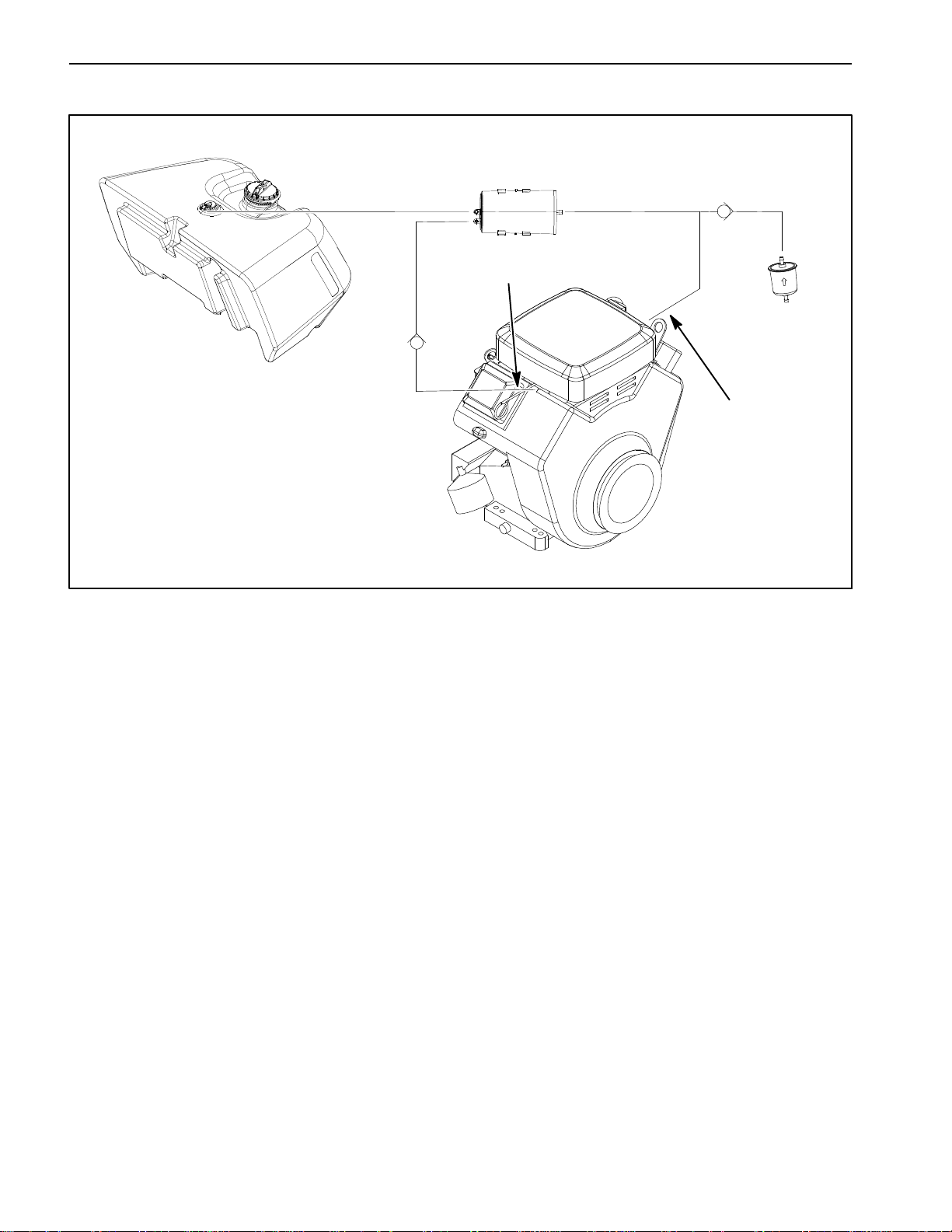
Fuel Evaporative Control System
FUEL
TANK
CHECK
VALVE
TO INTAKE
MANIFOLD
Figure 5
CARBON
CANNISTER
CHECK
VALVE
FRESH AIR
FILTER
TO AIR
CLEANER
ENGINE
Greensmaster 3150 machines are equipped with a fuel
evaporative control system designed to collect and
store evaporative emissions from the fuel tank. The
evaporate control system uses a carbon cannister to
collect these evaporative emissions. Fuel vapors from
the fuel tank are vented to the canister. Vaporsfrom the
canister are consumed when the engine is running.
The fuel tank on Greensmaster 3150 machines uses a
non--vented fuel cap. Toconnect the tank to the evaporativecontrolsystem,afuel tankventfittingispositioned
inthetop of the tankthatallows tank ventingthroughthe
carbon cannister.
NOTE: If there is restriction in the carbon cannister or
the fuel tank vent fitting, the fuel tank may distort due to
venting issues. If the fuel tank returns to it’s normal
shape when the fuel cap is removed, restriction in the
evaporative control system is likely.
The carbon canister is mounted on the hydraulic leak
detector tank (Fig. 6). The evaporative system includes
two(2)connections totheengine:onetotheintakemanifold and the second to the air cleaner base. Venting
hose assemblies (purgehose assembly and t--hose assembly) include check valves in two (2) locations as
showninFigure5.
NOTE: The purge hose assembly (item 5 in Fig. 6) and
teehoseassembly(item10inFig.6)bothincludea
check valve asa componentof t he hose assembly.The
check valve is not available as a separate part. To ensureproperoperationof check valves, donot attempt to
remove them from the hose assembly.If either of these
hose assemblies is removed, make sure that they are
correctly installed to ensure proper operation of the
evaporative control system.
Greensmaster 3150Page 3 -- 10Engine
Page 27
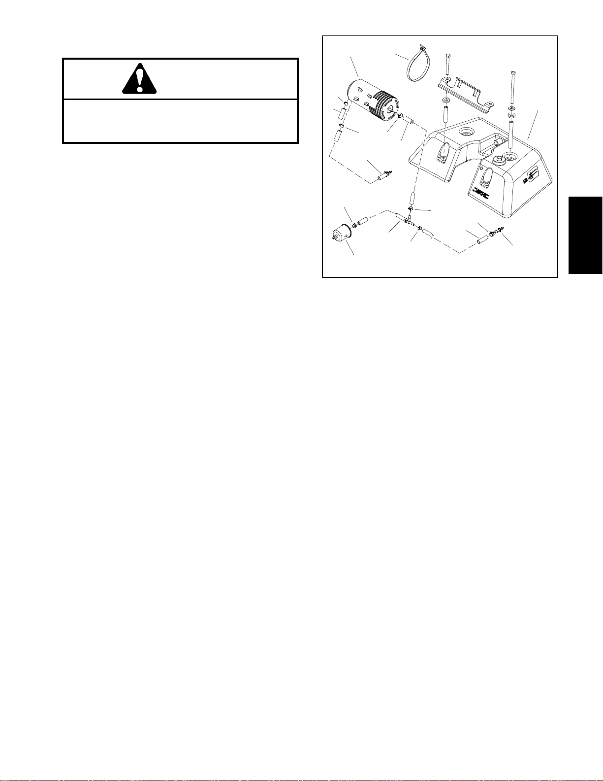
Disassembly (Fig. 6)
DANGER
Gasolineisflammable.Use caution whenstoring
or handling it. Wipe up any spilled fuel before
starting the engine.
1. Inspect carbon cannister and attached hoses for
damageorobviousleaks. Adamagedorleakingcannister should be replaced.
2. Remove components as needed using Figure 6 as
a guide.
A. If either purgehose assembly(item 5) or T--hose
assembly (item 10) is to be removed, label ends of
hose for assembly purposes. Both of these assembliesincludea check valve so direction ofinstallation
is important for correct operation of the evaporative
controlsystem. The check valveisnot available as a
separatepartsohose assembly replacement is necessary if the check valve or hose is faulty. To ensure
proper operation of check valves, do not attempt to
remove them from the hose assembly.
2
6
7
4
11
1. Leak detector tank
2. Carbon cannister
3. Cable tie (2 used)
4. Hose clamp
5. Purge hose assembly
6. Hose clamp
7. Hose (to fuel tank vent)
3
4
8
5
9
10
4
8
4
12
Figure 6
8. Hose clamp
9. Hose (to t--fitting)
10. T--hose assembly
11. Fresh air filter
12. Hose (to air cleaner)
13. Barbed fitting
13
1
Engine
Assembly
1. Install all removed components using Figure 6 as a
guide.
A. If either purgehose assembly(item 5) or T--hose
assembly (item 10) was removed, make sure that
installation is correct.
B. Make sure that fuel hoses are not kinked after
installation.Also,secureallhoseswithhoseclamps.
Greensmaster 3150 Page 3 -- 11 Engine
Page 28

This page is intentionally blank.
Greensmaster 3150Page 3 -- 12Engine
Page 29

Table of Contents
Chapter 4
Hydraulic System
SPECIFICATIONS 2............................
GENERAL INFORMATION 3.....................
Operator’s Manual 3...........................
Check Hydraulic System Fluid 3.................
Towing Traction Unit 4.........................
Hydraulic Hoses 4.............................
Hydraulic Hose and Tube Installation (O--Ring
Face Seal Fitting) 5..........................
Hydraulic Fitting Installation (SAE Straight Thread
O--Ring Fitting into Component Port) 6.........
HYDRAULIC SCHEMATIC 8.....................
HYDRAULIC FLOW DIAGRAMS 10...............
Traction Forward and Reverse 10................
Raise and Lower Cutting Units 12................
Mow and Backlap 14...........................
Right and Left Turn 16.........................
SPECIAL TOOLS 18............................
TROUBLESHOOTING 21........................
General Hydraulic System Problems 21..........
Traction Circuit Problems 22...................
Mow Circuit Problems 23......................
Lift/Lower Circuit Problems 24..................
Steering Circuit Problems 25...................
TESTING 26...................................
Precautions for Hydraulic T esting 26.............
Charge Relief Valve Pressure Test 28............
Wheel Motor Efficiency Test 30..................
Piston (Traction) Pump Flow Test 32.............
Gear Pump (Rear Section) Flow Test 34..........
Implement Relief Valve Pressure Test 36.........
Lower Cutting Units Relief Valve (R2)
Pressure Test 38.............................
Gear Pump (Front Section) Flow Test 40.........
Mow Circuit Relief Valve (S1R1) Pressure Test 42.
Reel Motor Case Drain Flow Test 44.............
Steering Control V alve Test 46..................
ADJUSTMENTS 49.............................
Adjust Manifold Relief Valves (R2) 49............
SERVICE AND REPAIRS 50.....................
General Precautions for Removing and
Installing Hydraulic System Components 50.....
Flush Hydraulic System 51......................
Filtering Closed--Loop Traction Circuit 52.........
Hydraulic System Start--up 53...................
Gear Pump 54................................
Gear Pump Service 56.........................
Piston (Traction) Pump 60......................
Piston (Traction) Pump Service 64...............
Piston Pump Crush Ring Replacement 66........
Front Wheel Motors 68.........................
Rear Wheel Motor (Optional 3WD) 70............
eel Motor Service 72........................
Wh
Cutting Reel Motors 74.........................
Cutting Reel Motor Service 78...................
Front Lift Cylinders 82..........................
Center Lift Cylinder 84.........................
Lift Cylinder Service 86.........................
Hydraulic Manifold 88..........................
Hydraulic Manifold Service 90...................
Steering Control Valve 94.......................
Steering Control Valve Service 96...............
Steering Cylinder 98...........................
Steering Cylinder Service 100...................
Leak Detector 102.............................
Hydraulic Reservoir 106........................
EATON, MEDIUM DUTY PISTON PUMP, REPAIR
INFORMATION, MODEL 70160 VARIABLE DISPLACEMENT PISTON PUMP
PARKER TORQMOTOR
(TC, TB, TE, TJ, TF, TG, TH and TL SERIES)
SAUER/DANFOSS STEERING UNIT TYPE OSPM
SERVICE MANUAL
TM
SERVICE PROCEDURE
System
Hydraulic
Greensmaster 3150 Hydraulic SystemPage 4 -- 1
Page 30

Specifications
Item Description
Piston (Traction) Pump Variabledisplacement piston pump
Maximum Pump Displacement (per revolution) 1.24 in
Charge Pressure 110to150PSI(8to10bar)
Gear Pump 2 section, positive displacement gear pump
Front Section (cutting reels) Displacement (per revolution) 0.58 in
Rear Section (steering/lift) Displacement (per revolution) 0.33 in
Front Wheel Motors Orbital rotor motor
Displacement (per revolution) 10.3 in
Rear Wheel Motor (Optional 3WD Kit) Orbital rotor motor
Displacement (per revolution) 20.6 in
Cutting Reel Motor Gear motor
Displacement (per revolution) 0.73 in
Steering Control Valve Distributor valve with rotary meter
Implement (Steering and Lift) Relief Pressure 1160PSI (80 bar) above Charge Pressure
Hydraulic Manifold Relief Valves
Mow Circuit (S1R1) 3000 PSI (207 bar)
Cutting Unit Lower (R2) 400 PSI (28 bar) above Charge Pressure
Hydraulic Filter Spin--on cartridge type
3
(20.3 cc)
3
(9.5 cc)
3
(5.4 cc)
3
(169 cc)
3
(337 cc)
3
(12 cc)
Hydraulic Oil See Operator’s Manual
Hydraulic Reservoir Reservoir (with leak detector) capacity 8.5 gal. U.S. (32.2 L)
Greensmaster 3150Hydraulic System Page 4 -- 2
Page 31

General Information
Operator’s Manual
The Operator’s Manual provides information regarding
the operation, general maintenance and maintenance
intervalsforyourGreensmaster3150.Refer to thatpublication for additional information when servicing the
machine.
Check Hydraulic System Fluid
The hydraulic system on the Greensmaster 3150 is designed to operate on high quality hydraulic fluid. Refer
to the Operator’s Manual for hydraulic fluid recommendations.
IMPORTANT: Check level of hydraulic fluid before
engine is first started and daily thereafter. Do not
overfill hydraulic reservoir.
2
NOTE: If changing from one type of hydraulic fluid to
another, be certain to remove all the old fluid from the
system, as some fluids are incompatible with others.
IMPORTANT: Use only types of hydraulic fluids
specifiedintheOperator’sManual. Otherfluidsmay
cause system damage.
NOTE: Ared dyeadditive for the hydraulicsystem fluid
is available in 2/3 oz bottles. One bottle is sufficient for
4 to 6gallons of hydraulicfluid. Order PartNo. 44--2500
from your Authorized Toro Distributor.
1
Figure 1
1. Sight window 2. Hydraulic oil cap
System
Hydraulic
Greensmaster 3150 Hydraulic SystemPage 4 -- 3
Page 32

Towing Traction Unit
In case of emergency, the Greensmaster 3150 can be
towed for a short distance. However,Toro does not recommend this as a standard practice.
IMPORTANT: Do not tow the machine faster than 2
to 3 mph because drive system may be damaged. If
machine must be moved a considerable distance,
transport it on a truck or trailer.
1
1. Locate by--pass valve on the rear side of the piston
pump.Rotatevalve90
2. Before starting engine,close by--pass valve byrotating it back 90
not start engine when the valve is open.
o
so the slot in the valve is horizontal. Do
o
sotheslotinthevalveisvertical.
Hydraulic Hoses
Hydraulichoses a re subject to extreme conditions such
aspressure differentialsduring operation and exposure
to weather, sun, chemicals, very warm storage conditionsormishandlingduringoperationandmaintenance.
These conditions can cause hose damage and deterioration. Some hoses are more susceptible to these
conditions than others. Inspect all machine hydraulic
hoses frequently for signs of deterioration or damage:
Hard, cracked, cut, abraded, charred, leaking or
otherwise damaged hose.
Kinked, crushed, flattened or twisted hose.
Blistered, soft, degraded or loose hose cover.
Cracked, damaged or badly corroded hose fittings.
When replacing a hydraulic hose, be sure that the hose
is straight (not twisted) before tightening the fittings.
This can be done by observing the imprint (layline) on
thehose. Usetwo wrenches; hold the hosestraight with
one wrench and tighten the hose swivel nut onto the fitting with the other wrench (see Hydraulic Hose and
Tube Installation in this section). If the hose has an elbowatoneend,tightentheswivelnut on that end before
tightening the nut on the straight end of the hose.
2
Figure 2
1. Piston pump 2. By--pass valve
WARNING
Beforedisconnecting or performing any work on
hydraulic system, relieve all pressure in system
(seeRelieving Hydraulic System Pressure in this
section).
Keepbodyand handsawayfrompin holeleaksor
nozzles that eject hydraulic fluid under high
pressure. Use paper or cardboard, not hands, to
search for leaks. Hydraulic fluid escaping under
pressure can have sufficient force to penetrate
the skin and cause serious injury. If fluid is injected into the skin, it must be surgically removed within a few hours by a doctor familiar
withthistypeofinjury.Gangrenemayresultfrom
such an injury.
For additional hydraulic hose information, refer to Toro
Service Training Book, Hydraulic Hose Servicing (Part
Number 94813SL).
Greensmaster 3150Hydraulic System Page 4 -- 4
Page 33

Hydraulic Hose and Tube Installation (O --Ring Face Seal Fitting)
1. Make sure threads andsealing surfaces ofthe hose/
tube and the fitting are free of burrs, nicks, scratches or
any foreign material.
2. Asa preventative measure againstleakage,it is recommended that the face seal O--ring be replaced any
time the connection is opened. Make sure the O--ring is
installedandproperly seatedinthefittinggroove.Lightly
lubricate the O--ring with clean hydraulic oil.
3. Place the hose/tube against the fitting body so that
theflatfaceof the hose/tubesleevefullycontactstheO-ring in the fitting.
4. Thread the swivel nut onto the fitting by hand. While
holding the hose/tube with a wrench, use a torque
wrench to tighten the swivel nut to the recommended
installation torque shown in Figure 5. This tightening
process will require the use of an offset wrench (e.g.
crowfoot wrench). Use of an offset wrench will affect
torque wrench calibration due to the effective length
change of the torque wrench. Tightening torque when
usingatorque wrenchwithanoffsetwrenchwillbelower
than the listed installation torque (see Using a Torque
Wrench with an Offset Wrench in the Torque Specificationssection of Chapter 2 -- Product Records and Maintenance).
C. Useasecondwrenchtotightenthenuttothecorrect Flats From Wrench Resistance (F.F.W.R.). The
markingsonthenutandfittingbody willverifythatthe
connection has been properly tightened.
Size F.F.W.R.
4 (1/4 in. nominal hose or tubing) 1/2 to 3/4
6 (3/8 in.) 1/2 to 3/4
8 (1/2 in.) 1/2 to 3/4
10 (5/8 in.) 1/2 to 3/4
12 (3/4 in.) 1/3 to 1/2
16 (1 in.) 1/3 to 1/2
Swivel Nut
Tubeor Hose
O--ring
Fitting Body
Figure 3
System
Hydraulic
5. If a torque wrench is not available or if space at the
swivelnutpreventsuseof a torque wrench, an alternate
method of assembly is the Flats From Wrench Resist-
Mark Nut
and Fitting
Body
Final
Position
ance (F.F.W.R.) method (Fig. 2).
A. Usingawrench,tightenthe swivel nut onto the fittinguntillight wrench resistance is reached(approximately 30 in--lb).
B. Mark the swivel nut and fitting body. Hold the
hose/tube with a wrench to prevent it from turning.
AT WRENCH RESISTANCE
Extend Line
Figure 4
Fitting Dash Size Hose/Tube Side Thread Size Installation Torque
4 9/16 -- 18 18to22ft--lb(25to29N--m)
6 11/16 -- 16 27to33ft--lb(37to44N--m)
8 13/16 -- 16 37to47ft--lb(51to63N--m)
10 1--14 60 to 74 ft--lb (82 to 100 N--m)
12 13/16--12 85to105ft--lb(116to142N--m)
16 17/16--12 110to136ft--lb(150to184N--m)
Initial
Position
AFTER TIGHTENING
20 1 11/16 -- 12 140 to 172 ft--lb (190 to 233 N--m)
Figure 5
Greensmaster 3150 Hydraulic SystemPage 4 -- 5
Page 34

Hydraulic Fitting Installation (SAE Straight Thread O--Ring Fitting into Component Port)
Non--Adjustable Fitting (Fig. 6)
1. Make sure all threads and sealing surfaces of fitting
and component port are free of burrs, nicks, scratches
or any foreign material.
2. As a preventative measure against leakage, it isrecommended that the O--ring be replaced any time the
connection is opened.
3. Lightly lubricate the O--ring with clean hydraulic oil.
Fittingthreadsshould becleanwithnolubricantapplied.
IMPORTANT: Before installing fitting into port, determine port material. If fitting is to be installed into
an aluminum port, installation torque is reduced.
4. Install the fitting into the port. Then, use a torque
wrench and socket to tighten the fitting to the recommended installation torque shown in Figure 7.
NOTE: Use of an offset wrench (e.g. crowfoot wrench)
will affect torque wrench calibration due to the effective
length change of the torque wrench. Tightening torque
when using a torque wrench with an offset wrench will
be less than the recommended installation torque. See
UsingaTorqueWrenchwithanOffsetWrenchinthe
Torque Specifications section of Chapter 2 -- Product
RecordsandMaintenancetodeterminenecessaryconversion information.
5. If a torque wrench is not available, or if space at the
portprevents use of a torque wrench,analternatemethod of assembly is the Flats From Finger Tight (F.F.F.T.)
method.
A. Install the fitting into the port and tighten it down
full length until finger tight.
B. If port material is steel, tighten the fitting to the
listed F.F.F.T. If port material is aluminum, tighten fitting to 60% of listed F.F.F.T.
Size F.F.F.T.
4 (1/4 in. nominal hose or tubing) 1.00+
6 (3/8 in.) 1.50 +
8 (1/2 in.) 1.50 +
10 (5/8 in.) 1.50 +
12 (3/4 in.) 1.50 +
16 (1 in.) 1.50 +
Fitting
O--ring
0.25
0.25
0.25
0.25
0.25
0.25
Figure 6
Fitting
Dash Size
Fitting Port Side
Thread Size
Installation Torque Into
Steel Port
Installation Torque Into
Aluminum Port
4 7/16 -- 20 15to19ft--lb(21to25N--m) 9to11ft--lb(13to15N--m)
5 1/2 -- 20 18to22ft--lb(25to29N--m) 11 to 15 ft--lb (15 to 20 N--m)
6 9/16 -- 18 34to42ft--lb(47to56N--m) 20to26ft--lb(28to35N--m)
8 3/4 -- 16 58to72ft--lb(79to97N--m) 35to43ft--lb(48to58N--m)
10 7/8 -- 14 99to121ft--lb(135to164N--m) 60 to 74 ft--lb (82 to 100 N--m)
12 11/16--12 134to164ft--lb(182to222N--m) 81 to 99 ft--lb (110 to 134 N--m)
14 13/16--12 160to196ft--lb(217to265N--m) 96to118ft--lb(131to160N--m)
16 15/16--12 202to248ft--lb(274to336N--m) 121to149ft--lb(165to202N--m)
20 15/8--12 247to303ft--lb(335to410N--m) 149to183ft--lb(202to248N--m)
Figure 7
Greensmaster 3150Hydraulic System Page 4 -- 6
Page 35

Adjustable Fitting (Fig. 8)
1. Make sure all threads and sealing surfaces of fitting
and component port are free of burrs, nicks, scratches
or any foreign material.
2. Asa preventative measure againstleakage,it is recommended that the O--ring be replaced any time the
connection is opened.
3. Lightly lubricate the O--ring with clean hydraulic oil.
Fittingthreadsshouldbe clean withnolubricantapplied.
4. Turnback the lock nut as far aspossible. Make sure
the back up washer is not loose and is pushed up as far
aspossible(Step1inFigure9).
IMPORTANT: Before installing fitting into port, determine port material. If fitting is to be installed into
an aluminum port, installation torque is reduced.
Lock Nut
Back--up Washer
O--ring
Figure 8
5. Install the fitting into the port and tighten finger tight
until the washer contacts the face of the port (Step 2).
6. Toputthefittingin the desired position, unscrew it by
the required amount, but no more than one full turn
(Step 3).
7. Hold the fitting in the desired position with a wrench
and use a torque wrench to tighten the fitting to the recommended installation torque shown in Figure 7. This
tightening process will require the use of an offset
wrench (e.g. crowfoot wrench). Use of an offset wrench
will affect torque wrench calibration due to the effective
length change of the torque wrench. Tightening torque
when using a torque wrench with an offset wrench will
be lower than the listed installation torque (see Using a
Torque Wrench with an Offset Wrench in the Torque
Specifications section of Chapter 2 -- Product Records
and Maintenance).
8. If a torque wrench is not available, or if space at the
portpreventsuseofatorquewrench, an alternatemethod of assembly is the Flats From Finger Tight (F.F.F.T.)
method.Holdthefittinginthedesiredpositionwitha
wrench and, if port material is steel, tighten the lock nut
withasecondwrenchtothelistedF.F.F.T(Step4).Ifport
material is aluminum, tighten fitting to 60% of listed
F.F.F.T.
Step 3Step 1
Step 2 Step 4
Figure 9
System
Hydraulic
Size F.F.F.T.
4 (1/4 in. nominal hose or tubing) 1.00+
6(3/8in.) 1.50+
8(1/2in.) 1.50+
10 (5/8 in.) 1.50 +
12 (3/4 in.) 1.50 +
16 (1 in.) 1.50 +
0.25
0.25
0.25
0.25
0.25
0.25
Greensmaster 3150 Hydraulic SystemPage 4 -- 7
Page 36

Hydraulic Schematic
VALVE
STEERING
Right
Motor
10.3
10.3
Left
Motor
3WD KIT
OPTIONAL
20.6
Steering Cylinder
L3A L3BL2B L1B
L2A
4.5
0.055
0.030
FC2
1.5” Bore
0.75” Rod
6.19” Stroke
LR
Raise
CU #3
2.0” Bore
0.75” Rod
1.88” Stroke
CU #1
0.75” Rod
1.50” Bore
3.38” Stroke
Lower
1160 PSI
S4
R2
400 PSI
PET
ST
S2
S3
2850/1650
ENGINE RPM
BYPASS
VALVE
A
TOP
PORT
TRANSPORT = 14.1 GPM
PT
4.0 GPM
TRACTION PUMP
P2
7.0 GPM
3000
PSI
3000
PSI
1.24
.33 .58
PUMP
GEAR
B
BOTTOM
PORT
70 to
100 PSI
110 to
150 PSI
G2
MB
MA L1A
0.055
MR
550 PSI
PRV
(SW)
SWITCH
BACKLAP
OR1
FC1
T
LC
0.013
S1R1
OR2
0.060
P1
G1
CU #2
2.0” Bore
0.75” Rod
1.88” Stroke
Center
Reel (#1)
.73
.73
Right Front
Reel (#3)
de--energized
All solenoids are shown as
Hydraulic Schematic
Greensmaster 3150
.73
Reel (#2)
Left Front
25 PSI
FILTER
OPTIONAL
OIL COOLER
SUCTION
STRAINER
IN
LEAK DETECTOR
LEAK
OUT
VOLUME
DETECTOR
TANK
EXPANSION
BREATHER
Greensmaster 3150Hydraulic System Page 4 -- 8
Page 37

This page is intentionally blank.
System
Hydraulic
Greensmaster 3150 Hydraulic SystemPage 4 -- 9
Page 38

Hydraulic Flow Diagrams
Steering Cylinder
1.5” Bore
0.75” Rod
6.19” Stroke
LR
4.5
1160 PSI
PET
VALVE
STEERING
TOP
Motor
Right
10.3
10.3
Left
Motor
2850/1650
ENGINE RPM
BYPASS
VALVE
A
PORT
3WD KIT
OPTIONAL
20.6
B
BOTTOM
PORT
70 to
100 PSI
TRANSPORT = 14.1 GPM
Raise
Lower
L3A L3BL2B L1B
L2A
MB
MA L1A
0.055
0.030
FC2
0.055
MR
BACKLAP
550 PSI
SWITCH
S4
R2
400 PSI
PRV
(SW)
CU #3
2.0” Bore
0.75” Rod
1.88” Stroke
CU #1
0.75” Rod
1.50” Bore
3.38” Stroke
de--energized.
All solenoids are shown as
Right Front
Reel (#3)
CU #2
2.0” Bore
0.75” Rod
1.88” Stroke
Center
Reel (#1)
.73
.73
.73
Reel (#2)
Left Front
ST
PT
4.0 GPM
TRACTION PUMP
S2
S3
P2
G2
T
0.013
OR2
LC
S1R1
0.060
P1
G1
OR1
FC1
7.0 GPM
25 PSI
FILTER
3000
PSI
3000
PSI
110 to
150 PSI
1.24
.33 .58
PUMP
GEAR
OPTIONAL
OIL COOLER
SUCTION
STRAINER
Greensmaster 3150
Traction Forward
IN
OUT
LEAK
VOLUME
DETECTOR
High Pressure
Low Pressure (Charge)
Return or Suction
Flow
LEAK DETECTOR
TANK
EXPANSION
BREATHER
Greensmaster 3150Hydraulic System Page 4 -- 10
Page 39

Traction Forward a nd Reverse
Forward
The piston (traction) pump is driven directly by the engine.Thetractioncircuitofthe hydraulic system acts essentiallyasaclosedloop.Takingitssuctiondirectlyfrom
thereturnsideofthewheelmotorsofthetractioncircuit,
the piston pump supplies oil flow to the wheel motors
through the supply side of the traction circuit.
Withtheengine runningandtraction pedal intheneutral
position, the piston pump supplies no flow to the wheel
motors. When the traction pedal is pressed to the forward position, the linkage from the pedal positions the
swash plate in the piston pump so oil flows out the top
port of the pump. Oil flow out of the top port goes to the
wheel motors and turns them in the forward direction.
Oilflowing out of thewheel motors returns to thebottom
port of the piston pumpand is continuously pumped out
the top port as long as the traction pedal is pressed for
the forward direction.
Hydraulic oil is supplied to the traction charge circuit
from the rear gear pump section though the steering
valve,control manifold and backthroughthe charge circuit check valves in the piston (traction) pump. This oil
replaces oil losses f rom flow through the internal case
drain, shuttle valve andsmall amounts of traction circuit
leakage. Charge circuit pressure is maintained by the
charge relief valve that is attached to the piston pump
back plate.
Reverse
The traction circuit operates essentially the same in reverse as it does in the forward direction. However, the
flow through the circuit is reversed.
Withtheenginerunningandtractionpedalintheneutral
position, the piston pump supplies no flow to the wheel
motors. When the traction pedal is pressed to t he reverse position, the linkage from the pedal positions the
swashplateinthepistonpumpsooilflowsoutthebottomportofthepump. Oilflowoutofthebottomportgoes
tothe wheel motors andturnsthem in the reversedirection.
Oilflowingoutofthewheelmotorsreturns to the top port
of the piston pump and is continuously pumped out the
bottom port as long as the traction pedal is pressed for
the reverse direction.
Thechargecircuitfunctions the same in reverse as it
does in the forward direction.
Traction Circuit Cooling
The piston pump includes a shuttle valve that bleeds off
asmallamountof hydraulicfluidforcoolingoftheclosed
looptraction circuit. This valve allowsa small amountof
hydraulic oil to pass from the low pressure side of the
traction circuit while operating the traction unit in either
direction. A relief valve in the piston pump back plate
prevents shuttle valve bleed off until the relief valve
opens(70 to100 PSI / 5to 7 bar). The charge circuit replenishes oil that is bled from the traction circuit by the
shuttle valve.
System
Hydraulic
NOTE: Theshuttlevalveassemblyislocatedinthepiston pump back plate. Access to the shuttle valve requires removal of the back plate from the piston pump.
Greensmaster 3150 Hydraulic SystemPage 4 -- 11
Page 40

Motor
Right
10.3
10.3
1.5” Bore
0.75” Rod
6.19” Stroke
Steering Cylinder
LR
4.5
1160PSI
PET
Left
Motor
2850/1650
ENGINE RPM
BYPASS
VALVE
A
TOP
PORT
3WD KIT
OPTIONAL
20.6
B
BOTTOM
PORT
SolenoidsS2andS3areshown
in the energized position.
Right Front
VALVE
STEERING
TRANSPORT = 14.1 GPM
All other solenoids are shown
Reel (#3)
as de--energized.
CU #3
2.0” Bore
0.75” Rod
1.88” Stroke
CU #1
0.75” Rod
1.50” Bore
3.38” Stroke
CU #2
2.0” Bore
0.75” Rod
1.88” Stroke
.73
Raise
Lower
0.055
L3A L3BL2B L1B
0.030
FC2
L2A
0.055
Center
Reel (#1)
.73
.73
Reel (#2)
Left Front
MB
MA L1A
MR
BACKLAP
550 PSI
SWITCH
S4
R2
400 PSI
PRV
(SW)
OR1
FC1
0.013
OR2
ST
PT
4.0 GPM
TRACTION PUMP
S2
S3
P2
G2
T
LC
S1R1
0.060
P1
G1
7.0 GPM
3000
25 PSI
FILTER
70 to
100 PSI
3000
PSI
PSI
110 to
150 PSI
1.24
.33 .58
PUMP
GEAR
OPTIONAL
OIL COOLER
SUCTION
STRAINER
Greensmaster 3150
High Pressure
Raise Cutting Units
Low Pressure (Charge)
IN
OUT
LEAK
VOLUME
DETECTOR
Return or Suction
Flow
LEAK DETECTOR
TANK
EXPANSION
BREATHER
Greensmaster 3150Hydraulic System Page 4 -- 12
Page 41

Raise and Lower Cutting Units
The t andem gear pump is directly coupled to the piston
(traction) pump. The rear gear pump section supplies
hydraulic flow for the steering circuit (priority flow), for
raisingand lowering thecutting units andfor the traction
charge circuit. The gear pumptakes itssuction from the
hydraulic reservoir. Maximum circuit pressure of 1160
PSI (80 bar) is limited by the relief valve located in the
steering valve.
During cutting unit hold (not raising or lowering) conditions,flowfromthereargearpumpsectionisby--passed
through the steering valve and de--energized solenoid
valve (S2) in the hydraulic manifold directly to the traction charge circuit. Flow in excess of charge circuit requirements then returns to the gear pump inlet.
Raise Cutting Units
When the cutting units are to be raised, hydraulic manifoldsolenoidvalve (S2) is energized andblocksflowdirectly to the traction charge circuit. Flow is directed to
energizedsolenoidvalve (S3), whichdirects flow tode-energized solenoid valve (S4) and the lift cylinders. Hydraulic pressure against the cylinder pistons moves
their shafts causing the cutting units to raise. At the
sametime,thepistonspushthehydraulicfluidoutofthe
lift cylinders and back through energized solenoidvalve
(S3) to the charge circuit. Raise speed for the front cutting units is controlled by a 0.055 orifice.A 0.030 orifice
inthereturn line for the centercutting unit allows a slight
delay in raising that cutting unit.
Lower Cutting Units
Circuit operation for lowering the lift cylinders is similar
to raising them. However, the solenoid valve (S3) remains de--energized and solenoid valve (S4) is energized. Flow is reversed to and from the lift cylinders,
lowering the cutting units.
Whenthecuttingunits are to belowered,solenoidvalve
(S2) is energized and blocks flow directly to the traction
charge circuit. Flow is directed to de--energized solenoid valve (S3), which directs flow to the lift cylinders.
Hydraulic pressure against the cylinder pistons moves
their shafts causing the cutting units to lower. At the
sametime,thepistonspushthehydraulicfluidoutofthe
liftcylindersto energized solenoid valve (S4).Flowcontinues back through solenoid valve (S3) to the charge
circuit. Lower speed for the front cutting units is controlled by the 0.055 orifice. A 0.030 orifice and adjustable flow control valve for the center cutting unit allows
a slight delay in lowering that cutting unit.
To control pressure while lowering the cutting units, the
system is equipped with adjustable relief valve (R2) in
the hydraulic manifold.
When solenoid valves (S2) and (S4) de--energize,
spring action returns the valves to their original position
and by--passes flow back to the traction charge circuit
stopping lift cylinder movement.
System
Hydraulic
When solenoid valves (S2) and (S3) de--energize,
spring action returns the valves to their original position
and by--passes flow back to the traction charge circuit
stoppingliftcylindermovement.Theliftcylinderposition
is locked in place since there is no complete circuit of
flow to and from the lift cylinders.
Greensmaster 3150 Hydraulic SystemPage 4 -- 13
Page 42

Motor
Right
VALVE
STEERING
10.3
10.3
Left
Motor
3WD KIT
OPTIONAL
20.6
Steering Cylinder
Solenoid S1R1 is shown
in the energized position.
Lower
L3A L3BL2B L1B
L2A
MB
MA L1A
4.5
0.055
0.030
FC2
0.055
550 PSI
MR
BACKLAP
1.5” Bore
0.75” Rod
6.19” Stroke
All other solenoids are shown
as de--energized.
.73
Right Front
Reel (#3)
LR
Raise
CU #3
2.0” Bore
0.75” Rod
1.88” Stroke
CU #1
0.75” Rod
1.50” Bore
3.38” Stroke
CU #2
2.0” Bore
0.75” Rod
1.88” Stroke
Center
Reel (#1)
.73
.73
Left Front
Reel (#2)
SWITCH
1160 PSI
PET
ST
PT
4.0 GPM
S4
R2
400 PSI
OR1
PRV
(SW)
0.013
OR2
0.060
FC1
S2
S3
P2
G2
T
LC
S1R1
P1
G1
TRACTION PUMP
7.0 GPM
TOP
BYPASS
A
PORT
TRANSPORT = 14.1 GPM
25 PSI
FILTER
2850/1650
ENGINE RPM
VALVE
3000
PSI
OPTIONAL
3000
1.24
.33 .58
GEAR
OIL COOLER
PSI
PUMP
B
BOTTOM
PORT
70 to
100 PSI
110 to
150 PSI
SUCTION
STRAINER
Greensmaster 3150
High Pressure
Mow
Low Pressure (Charge)
Return or Suction
Flow
LEAK DETECTOR
IN
OUT
LEAK
VOLUME
DETECTOR
TANK
EXPANSION
BREATHER
Greensmaster 3150Hydraulic System Page 4 -- 14
Page 43

Mow and Backlap
The t andem gear pump is directly coupled to the piston
(traction) pump. The front gear pump section supplies
oil flow tothe hydraulic manifold block and to the cutting
reel motors. The gear pump takes its suction directly
from the hydraulic reservoir. Maximum circuit pressure
islimitedbysolenoid relief valve(S1R1)whichislocated
in the hydraulic manifold.
With the engine running and the functional control and
joystick levers positioned so the reels will not turn (see
Operator’s Manual), solenoid relief valve (S1R1) in the
hydraulic manifold is de--energized. The de--energized
(S1R1) by--passes flow from the front gear pump section to the oil filter and hydraulic reservoir. Additionally,
the manifold pressure reducing valve (PRV) will remain
seatedto prevent the reelmotors (and reels)from rotating.
Mow
With the engine running and the functional control and
joystick levers positionedso thereels will turn (see Operator’s Manual), solenoid relief valve (S1R1) is energized.Intheenergizedposition,thisvalvedirectsoilflow
to the reel motors and also functions as the mow circuit
relief valve.
Oil flow from manifold port (P1) flows through the reel
speed control valve (FC1). Flow across the speed controlvalveis pressurecompensatedbythelogiccartridge
valve (LC). The logic cartridge valve maintains a pressure differential of 75 PSI (5.2 bar) across the speed
control valve. Any excess flow above t he speed control
valve setting is by--passed to the reservoir through the
logiccartridge valve. With the backlap valve (MR) in the
mow position, oil flows through the backlap valve, out
manifold port (MA) and to the reel motors that are connected in series. Oil flows through the left front reel motor, right front motor and then center motor to turn the
reel motors in the mow direction.
When in the mow position, mow circuit pressure will
cause the hydraulic manifold pilot piston to shift and
open the pressure reducing valve ( PRV). The shifted
pressurereducing valve allows circuit oil to returnto the
reservoir through the manifold block, oil filter and oil
cooler (if equipped).
Backlap
Backlapping operation is the same as mowing operation, except for the position of the backlap valve (MR).
Whenthebacklapvalve(MR) is in the backlap position,
oil flows through the backlap valve, out manifold port
(MB)andtothereelmotorsthatareconnected in series.
Oil flows through the center reel motor,right front motor
andthen left front motoras it turns thereel motors inthe
backlap direction.
System
Hydraulic
Greensmaster 3150 Hydraulic SystemPage 4 -- 15
Page 44

Steering C ylinder
Motor
Right
10.3
10.3
Left
Motor
1.5” Bore
0.75” Rod
6.19” Stroke
LR
4.5
1160PSI
PET
VALVE
STEERING
2850/1650
ENGINE RPM
BYPASS
VALVE
A
TOP
PORT
3WD KIT
OPTIONAL
20.6
B
BOTTOM
PORT
70 to
100 PSI
All solenoids are shown
TRANSPORT = 14.1 GPM
OR1
FC1
0.013
OR2
ST
PT
4.0 GPM
TRACTION PUMP
S2
S3
P2
G2
T
LC
S1R1
0.060
P1
G1
7.0 GPM
25 PSI
FILTER
Raise
Lower
L3A L3BL2B L1B
L2A
MB
MA L1A
0.055
0.030
FC2
0.055
550 PSI
MR
SWITCH
BACKLAP
S4
R2
400 PSI
PRV
(SW)
CU #3
2.0” Bore
0.75” Rod
1.88” Stroke
as de--energized.
Power steering valve is
positioned for a right turn.
CU #1
0.75” Rod
1.50” Bore
3.38” Stroke
CU #2
2.0” Bore
0.75” Rod
1.88” Stroke
Center
Reel (#1)
.73
Right Front
.73
Reel (#3)
.73
Reel (#2)
Left Front
3000
3000
PSI
PSI
110 to
150 PSI
1.24
.33 .58
PUMP
GEAR
OPTIONAL
OIL COOLER
SUCTION
STRAINER
Greensmaster 3150
Right Turn
IN
OUT
LEAK
VOLUME
DETECTOR
High Pressure
Low Pressure (Charge)
Return or Suction
Flow
LEAK DETECTOR
TANK
EXPANSION
BREATHER
Greensmaster 3150Hydraulic System Page 4 -- 16
Page 45

Right and Left Turn
The t andem gear pump is directly coupled to the piston
(traction) pump. The rear gear pump section supplies
hydraulic flow for the steering circuit (priority flow), for
raisingand lowering thecutting units andfor the traction
charge circuit. The gear pumptakes itssuction from the
hydraulic reservoir. Maximum circuit pressure of 1160
PSI (80 bar) is limited by the relief valve located in the
steering valve.
With the steering wheel in the neutral position and the
engine running, the spool valve in the steering valve is
in the center position. Flow enters the steering control
valve at Port (P) and goes through the spool valve, by-passing the steering cylinder. Flow leaves the control
valve out port (E) to be available for the raise/lower and
traction charge circuits.
Right Turn
When a right turn is made with the engine running, the
turningofthesteering wheel positions the spoolvalvein
the steering valve so that flow goes through the bottom
of the spool. Flow entering the steering valve at Port (P)
goesthroughthespool andisroutedtotwoplaces.First,
most of the flow through the valve is by--passed out
steering valve port (E) and is available for raising and
loweringthe cutting unitsand for the traction chargecircuit.Second,the remainder of theflowis drawn through
the steering valve rotary meter and out steering valve
port (R). Pressure moves the steering cylinder piston to
extend the cylinder for a right turn. The rotary meter ensuresthattheoilflowtothecylinderisproportionaltothe
amount of turning on the steering wheel. Fluid leaving
the cylinder flowsback through the spool valve then out
steering valve port (T) and then to the traction charge
circuit.
Left Turn
When a left turn is made with the engine running, the
turningofthe steering wheel positions the spoolvalvein
the steering valve so that flow goes through the top of
the spool (Fig. 10). Flow entering the steering valve at
Port (P) goes through the spool and is routed to two
places. First, most of the flow through the valve is by-passed out steering valve port(E)andisavailablefor
raisingandloweringthecutting units and for thetraction
charge circuit. Second, the remainder of the flow is
drawn through the steering valve rotary meter and out
steeringvalveport(L).Pressuremovesthesteeringcylinder piston to retract the cylinder for a left turn. The
rotary meter ensures that the oil flow to the cylinder is
proportional to the amount of turning on the steering
wheel. Fluid leaving the cylinder flows back through the
spool valve then out steering valve port (T) and then to
thetractionchargecircuit.
The steering valve returns to the neutral position when
turning is complete.
Steering Cylinder
1.5” Bore
0.75” Rod
6.19” Stroke
LR
4.5
System
Hydraulic
The steering valve returns to the neutral position when
turning is complete.
Greensmaster 3150 Hydraulic SystemPage 4 -- 17
STEERING
VALVE
To Manifold
Port ST
To Manifold
Port P2
From Gear Pump
1160PSI
PET
Figure 10
Page 46

Special Tools
Order these special tools from your Toro Distributor.
Hydraulic Pressure Test Kit
Use to take various pressure readings for diagnostic
tests. Quick disconnect fittings provided attach directly
to mating fittings on machine test ports without tools. A
high pressure hose is provided for remote readings.
Contains one each: 1000 PSI (70 Bar), 5000 PSI (350
Bar) and 10000 PSI (700 Bar) gauges. Use gauges as
recommended in the Testing section of this chapter.
Toro Part Number: TOR47009
Hydraulic Tester (Pressure and Flow)
This tester requires O--ring Face Seal (ORFS) adapter
fittings for use o n this machine (see Hydraulic Test Fitting Kit (TOR4079) in this section).
Figure 11
1. INLET HOSE: Hose connected from the system circuit to the inlet side of the hydraulic tester.
2. LOAD VALVE: A simulated working load is created
in the circuit by turning the valve to restrict flow.
3. PRESSURE GAUGE: 0 to 5000 PSI gauge to provide operating circuit pressure.
4. FLOW METER: This meter measures actual oil flow
intheoperatingcircuitwithagaugeratedat15GPM.
5. OUTLET HOSE: A hose from the outlet side of the
hydraulictesterconnectstothehydraulicsystemcircuit.
Toro Part Number: TOR214678
O--ring Kit
The O--ring kit includes O--rings in a variety of sizes for
face seal and port seal hydraulic connections. It is recommended that O--rings be replaced whenever a hydraulic connection is loosened.
Toro Part Number: 117- -2727
Figure 12
Figure 13
Greensmaster 3150Hydraulic System Page 4 -- 18
Page 47

High Flow Hydraulic Filter Kit
The high flow hydraulic filter kit is designed with large
flow (40 GPM/150 LPM) and high pressure (5000
PSI/345 bar) capabilities. This kit provides for bi--directional filtration which prevents filtered debris from being
allowedbackinto the circuit regardlessofflow direction.
If a component failure occurs in the closed looptraction
circuit, contamination from the failed part will remain in
the circuit until removed. When connecting hydraulic
test gauges in order to test traction circuit components
orafterreplacinga failedtractioncircuitcomponent(e.g.
piston(traction)pump or wheelmotor),the high flow hydraulic filter can be installed in the traction circuit. The
filterwillensurethatcontaminates are removed fromthe
closed loop and thus, do not cause additional component damage.
Toro Part Number: TOR6011
NOTE: This kit does not include hydraulic hoses (see
Hydraulic Hose Kit TOR6007 above).
NOTE: Replacementfilter element is Toro part n umber
TOR6012. Filter element cannister tightening torque is
2 5 f t -- l b ( 3 4 N -- m ) .
Figure 14
System
Hydraulic
Hydraulic Hose Kit
This kit includes hydraulic fittings and hoses needed to
connect40GPMhydraulictester(AT40002)orhighflow
hydraulic filter kit (TOR6011)to machine hydraulic traction system components.
Toro Part Number: TOR6007
Figure 15
Greensmaster 3150 Hydraulic SystemPage 4 -- 19
Page 48

Hydraulic Test Fitting Kit
This kit includes a variety of O--ring face seal fittings to
enable you to connect test gauges into the system.
The kit includes: tee’s, unions, reducers, plugs, caps
and male test fittings.
Toro Part Number: TOR4079
Measuring Container
Use this container for doing hydraulic motor e fficiency
testing(motors with case drainlinesonly). Measure efficiency of a hydraulic motor by restricting the outlet flow
from the motor and measuring leakage from the case
drainlinewhilethemotorispressurizedby the hydraulic
system.
TORO TEST FITTING KIT (NO. TOR4079)
Figure 16
Toro Part Number: TOR4077
Wheel Hub Puller
The wheel hub puller allows safe removal of the wheel
hub from the shaft of wheel motors.
Toro Part Number: TOR4097
Figure 17
Figure 18
Greensmaster 3150Hydraulic System Page 4 -- 20
Page 49

Troubleshooting
The charts that follow contain information to assist in
troubleshooting. There may possibly be more than one
cause for a machine malfunction.
Refer to the Testing section of this Chapter for precautions and specific test procedures.
General Hydraulic System Problems
Problem Possible Cause
Hydraulic oil leaks from system. Fitting(s), hose(s) or tube(s) are loose or damaged.
O--r ing(s) or seal(s) are missing or damaged.
Hydraulic fluid foams. Hydraulic reservoir oil level is low.
Hydraulic system has wrong type of oil.
The pump suction line has an air leak.
Hydraulic system operates hot. Hydraulic reservoir oil level is low.
Suction screen in reservoir is loose or clogged.
Oil is contaminated or too light.
Brakes are applied or are incorrectly adjusted.
System
Hydraulic
Piston pump by--pass valve is open or defective.
Working load of machine (e.g. high ambient temperatures, use of
verticutter) may require use of oil cooler.
Oil cooler (if installed) is damaged or plugged. Cooler by--pass re-
lief is stuck open or air flow is obstructed.
Charge pressure is low (see Charge Pressure Relief Valve Pres-
sure Test in the Testing section of this chapter).
Wheel motor(s) or cutting reel motor(s) are worn or damaged (see
Wheel Motor Efficiency and Reel Motor Case Drain Flow Tests in
the Testing section of this chapter).
Piston (traction) pump is worn or damaged (see Piston (Traction)
Pump Flow Test in the Testing section of this chapter).
Greensmaster 3150 Hydraulic SystemPage 4 -- 21
Page 50

Traction Circuit Problems
Problem Possible Cause
Neutral is difficult to find or machine
operates in one direction only.
Traction response is sluggish. Hydraulic oil is very cold.
No traction exists in either direction. Brakes are applied or are incorrectly adjusted.
External control linkage is misadjusted, disconnected, binding or
damaged.
Piston (traction) pump is worn or damaged (see Piston (Traction)
Pump Flow Test in the Testing section of this chapter).
Brakes are applied or are incorrectly adjusted.
Piston pump by--pass valve is open or defective.
Charge pressure is low (see Charge Pressure Relief Valve Pres-
sure Test in the Testing section of this chapter).
Piston (traction) pump relief valves are leaking or damaged.
Piston (traction) pump or wheel motor(s) are worn or damaged (see
Piston (Traction) Pump Flow and Wheel Motor Efficiency Tests in
the Testing section of this chapter).
Hydraulic reservoir oil level is low (other hydraulic circuits affected
as well).
Piston pump by--pass valve is open.
Charge pressure is low (see Charge Pressure Relief Valve Pres-
sure Test in the Testing section of this chapter).
Wheel motor(s) are worn or damaged (see Wheel Motor Efficiency
Test in the Testing section of this chapter).
Piston (traction) pump is worn or damaged (see Piston (Traction)
Pump Flow Test in the Testing section of this chapter).
Wheel motor will not turn. Brakes are binding.
Key on wheel motor shaft is sheared or missing.
Wheel motor is damaged.
Wheel motor will not hold load in
neutral.
NOTE: The piston (traction) pump used on Greensmaster 3150 machines is equipped with relief valves
forboththeforwardandreversedirection.Due toengine
output,itisunlikely thattractionpressurewillreachrelief
valve settings. If, however,a piston pump relief valve is
leaking or otherwise faulty, traction performance would
be affected.
Make up fluid from charge pump is not available.
Piston (traction) pump relief valves are leaking or damaged.
Greensmaster 3150Hydraulic System Page 4 -- 22
Page 51

Mow Circuit Problems
Problem Possible Cause
Gear pump is noisy (cavitation). Hydraulic reservoir oil level is low (other hydraulic circuits affected
as well).
Hydraulic pump suction line is restricted.
Hydraulic pump suction line has an air leak.
Cutting reel motors will not turn. Hydraulic manifold solenoid valve S1R1 is stuck open (not shifting
to its energized position).
An electrical problem exists (see Chapter 5 -- Electrical System).
FC1 logic valve in control manifold is stuck open.
PRV valve in control manifold is stuck closed.
Pilot piston in control manifold is stuck or damaged.
Front section of gear pump is damaged (see Gear Pump (Front
Section) Flow Test in the Testing section of this chapter).
Cutting reel speed is erratic. A cutting unit problem exists (see Chapter 7 -- DPA Cutting Units).
System
Hydraulic
Hydraulic manifold reel circuit cartridge is leaking or damaged.
Hydraulic manifold orifice (OR1 or OR2) is plugged.
Cutting reel speed is low. A cutting unit problem exists (see Chapter 7 -- DPA Cutting Units).
Hydraulic manifold reel circuit cartridge is leaking or damaged.
Excessive internal wear in reel motor exists (see Reel Motor Case
Drain Flow Test in the Testing section of this chapter).
Greensmaster 3150 Hydraulic SystemPage 4 -- 23
Page 52

Lift/Lower Circuit Problems
Problem Possible Cause
Cutting units will not lift or lift slowly. Engine speed is too low.
Hydraulic reservoir oil level is low.
Lift cylinder linkage is binding or broken.
Lift cylinder bushings are binding or worn.
Charge circuit pressure is low (seeChargeReliefValvePressure
Test in the Testing section of this chapter).
Implement relief valve is leaking or damaged (see Implement Relief
Valve Pressure Test in the Testing section of this chapter).
Hydraulic manifold solenoid valve (S2) is leaking or damaged (not
shifting to its energized position).
Relief valve (R2) is leaking or damaged (see Lower Cutting Units
Relief Valve (R2) Pressure Test in the Testing section of this
chapter).
Lift cylinders leak internally.
Cutting units raise, but will not stay
up.
Spoolinsteeringcontrolvalveishungup(seeSteeringControl
Valve Test in the Testing section of this chapter).
Gear pump (rear section) is worn or damaged (see Gear Pump
(Rear Section) Flow Testin the Testing section of this chapter).
Hydraulic manifold solenoid valve (S4) leaks or is damaged.
Lift cylinders leak internally.
Greensmaster 3150Hydraulic System Page 4 -- 24
Page 53

Steering Circuit Problems
Problem Possible Cause
Steering wheel is hard to turn. Oil supply to the steering control valve is insufficient (traction
charge and lift circuits affected as well).
Emergency steering ball in steering control valve is missing or
damaged.
Regular adjustments to steering
wheel are necessary because of difficulty of driving in a straight line.
Steering wheel will not return to the
neutral position.
Steering wheel can turn on its own. Leaf springs in steering control valve are broken or stuck.
Backlash results when turning steering wheel.
Rear wheel shimmies when the
steering wheel is turned.
Thesteeringwheelcanbeturned
without the rear wheel turning.
Leaf springs in steering control valve are worn or broken.
Gear wheel set in steering control valve is worn.
Steering cylinder is seized or its piston seals are worn (see Steer-
ing Control Valve Test in the Testing section of this chapter).
Spool and sleeve are sticking to steering control housing assembly
(see Steering Control Valve Test in the Testing section of this
chapter).
Spool and sleeve are sticking to steering control housing assembly
(see Steering Control Valve Test in the Testing section of this
chapter).
Cardan shaft fork is worn or broken.
Leaf springs in steering control valve are worn or broken.
Air is in the steering cylinder.
Mechanical connections to the wheel or wheel bearing are worn.
The steering cylinder is worn.
The gear set in the steering control valve is worn.
System
Hydraulic
Steering response is too slow and
heavywhentryingtoturnquickly.
Turning steering wheel turns machine in the opposite direction.
Steering force (possibly to one side
only) is insufficient.
Greensmaster 3150 Hydraulic SystemPage 4 -- 25
Oil supply to the steering control valve is insufficient (traction
charge and lift circuits affected as well).
Hoses to the steering cylinder are reversed.
Hydraulic flow to steering control valve is low (traction charge and
lift circuits affected as well).
Implement relief valve is leaking or damaged (see Implement Relief
Valve Pressure Test in the Testing section of this chapter).
Page 54

Testing
The most effective method for isolating problems in the
hydraulic system is by using hydraulic test equipment
such as pressuregauges and flowmeters in the circuits
during various operational checks (see the Special
Tools section in this Chapter).
Before Performing Hydraulic Tests
IMPORTANT: All obvious areas such as oil supply,
filter, binding linkages, loose fasteners, improper
adjustments, solenoid valve operation or electrical
connections/circuits must be checked before assuming that a hydraulic component is the source of
the problem.
Precautions for Hydraulic Testing
CAUTION
Failure to use gauges with recommended pressure (psi) rating as listed in test procedures
couldresultin damage tothegaugeandpossible
personal injury from leaking hot oil.
All testing should be performed by two (2)
people.Onepersonshouldbein the seat to operate the machine and the other should read testing tools (e.g. pressure gauge) and record test
results.
Operate all hydraulic controls to relieve system
pressure and avoid injury from pressurized hydraulic oil. Controls must be operated with the
ignitionswitchinOFF.Removekey from the ignition switch.
1. Clean machine thoroughly before disconnecting or
disassemblinganyhydraulic components. Always keep
in mind the need for cleanliness when working on hydraulic equipment. Contamination will cause excessive
wear of components.
2. Topreventhydraulicsystem contamination, put metal caps or plugs on any hydraulic lines left open or exposed during testing or removal of components.
3. Theengine must be ingoodoperatingcondition. Enginespeed will affecttest accuracy.Check pump speed
with a phototac when performing hydraulic tests.
4. When using tester with pressure and flow capabilities,the inlet and theoutlethoses must be properly connected and not reversed to prevent damage to the
hydraulic tester or components.
5. When using tester with pressure and flow capabilities, completely open load valve in the hydraulic tester
to minimize the possibility of damaging components.
6. Install fittings finger tight and far enough to make
sure that they are not cross--threaded before tightening
them with a wrench.
7. Position tester hoses to prevent rotating machine
partsfromcontactinganddamagingthehoses or tester.
8. Check oil level in the hydraulic reservoir. After connecting test equipment, make sure tank is full.
9. Check control linkages for improper adjustment,
binding,or broken parts.
10.All hydraulic testsshouldbe made with the hydraulic
oil at normal operating temperature.
WARNING
Beforedisconnectingor performinganyworkon
the hydraulic system, all pressure in the system
must be relieved and all rotating machine parts
must be stopped. Stop engine; lower or support
attachments.
Keep body and hands away from pin hole leaks
or nozzles that eject hydraulic fluid under high
pressure. Do not use hands to search for leaks;
use paper or cardboard. Hydraulic fluid escaping under pressure can have sufficient force to
penetrate the skin and cause serious injury. If
fluid is injected into theskin, it must be surgically removed within a few hours by a doctor familiar with this type of injury. Gangrene may result
from such an injury.
11.Record the results of all performed hydraulic tests.
Hydraulic Testing
1. Use the Hydraulic Schematic, Hydraulic Flow Diagrams and the Troubleshooting section found in this
Chapter to assist in problem identification and solution.
2. Hydraulic system problems (e.g. low hydraulic oil
level, contaminated oil, incorrect engine speed) will affect the entire hydraulic system.
3. For traction related problems (e.g. machine will not
go up an incline), consider performing the following hydraulic tests:
Charge Pressure Relief Valve Pressure Test
Wheel Motor Efficiency Test
Piston (Traction) Pump Flow Test
Greensmaster 3150Hydraulic System Page 4 -- 26
Page 55

4. For problems with steering or cutting unit lift/lower,
consider performing the following hydraulic tests:
Charge Pressure Relief Valve Pressure Test
Lower Cutting Units Relief Valve (R2) Pressure Test
Implement Relief Valve Pressure Test
Gear Pump (Rear Section) Flow Test
Steering Valve Test
5. Forissueswiththe cuttingsystem,considerperforming the following hydraulic tests:
Mow Circuit Relief Valve (S1R1) Pressure Test
Reel Motor Case Drain Flow Test
Gear Pump (Front Section) Flow Test
System
Hydraulic
Greensmaster 3150 Hydraulic SystemPage 4 -- 27
Page 56

Charge Relief Valve Pressure Test (Using Pressure Gauge)
VALVE
STEERING
Right
Left
Motor
10.3
10.3
3WD KIT
OPTIONAL
20.6
Motor
1.5” Bore
0.75” Rod
6.19” Stroke
Steering Cylinder
LR
4.5
1160 PSI
PET
TOP
2850/1650
ENGINE RPM
BYPASS
VALVE
A
PORT
B
BOTTOM
PORT
70 to
100 PSI
PRESSURE
GAUGE
Raise
Lower
CU #3
2.0” Bore
0.75” Rod
1.88” Stroke
CU #1
0.75” Rod
1.50” Bore
3.38” Stroke
0.055
L3A L3BL2B L1B
0.030
FC2
S4
R2
400 PSI
L2A
ST
PT
4.0 GPM
S2
S3
P2
7.0 GPM
TRANSPORT= 14.1 GPM
3000
PSI
3000
PSI
110 to
150 PSI
1.24
TRACTION PUMP
.33 .58
PUMP
GEAR
Right Front
G2
CU #2
2.0” Bore
0.75” Rod
1.88” Stroke
0.055
25 PSI
T
0.013
OR2
LC
FILTER
S1R1
0.060
OPTIONAL
OIL COOLER
SUCTION
STRAINER
P1
G1
Center
Reel (#1)
.73
.73
Reel (#3)
.73
Reel (#2)
Left Front
550 PSI
MR
MB
OR1
PRV
FC1
MA L1A
(SW)
SWITCH
BACKLAP
IN
LEAK DETECTOR
LEAK
DETECTOR
OUT
VOLUME
TANK
BREATHER
EXPANSION
Greensmaster 3150Hydraulic System Page 4 -- 28
Page 57

Procedure for Charge Relief Valve Pressure
1. Make sure hydraulic oil is at normal operating temperaturebyoperating themachineforapproximatelyten
(10) minutes.
2. Parkmachineonalevelsurface withthecuttingunits
lowered. Make sure engine is off and the parking brake
is engaged. Make sure the hydraulic reservoir is full.
Test
CAUTION
Before continuing further, read and become familiar with Precautions for Hydraulic Testing.
3. Install 1000 PSI (70 bar) pressure gauge with hydraulic hose attached to test port in the tee fitting on the
bottom of the control m anifold (Fig. 19).
4. Make sure that traction pedal, steering wheel and
joystick control are in the neutral position.
5. Start engine and operate at high idle speed (2850 +
50 RPM).
C. While monitoring the pressure gauge, push the
traction pedal to allow traction system load.
D.Thechargepressureshoulddropnomorethan
20% from no --load charge pressure measured in
step 6 above(e.g. if charge pressure in step 6 is 125
PSI (9 bar), charge pressure in forward or reverse
under load should be more than 100 PSI (7 bar).
E. If charge pressure is good under no load, but
drops below specification when under traction load,
the piston (traction) pump and/or wheel motors
should be suspected of wear and inefficiency.When
thepumpand/ortractionmotor(s)arewornordamaged,thechargepumpis not able tokeepupwith internalleakagein tractioncircuitcomponents.Further
testing of the traction circuit should be completed
(see Piston (Traction) Pump Flow and Wheel Motor
Efficiency Tests in this section).
10.When charge pressure testing is complete, disconnect pressure gauge from the test port and install dust
cap on test port.
System
Hydraulic
6. Pressure gauge should read approximately 100 to
150PSI(7to10bar).
7. Shut off engine. Record test results.
8. If specification is not met, remove piston pump back
plateassemblythatcontainsthechargereliefvalve(see
Piston (Traction) Pump Service in the Service and Repairs section of this chapter). Repair or replace relief
valve components as necessary.
9. Adynamicchargepressure test canbeperformedas
follows:
A. Positionmachine so that a loadcan be placedon
thetractionsystem.For example, chain the machine
to an immovable object or chock all drive wheels to
prevent the machine from moving.
B. With pressure gauge still connected to control
manifold test port, sit in the operator seat, start the
engineandmovethrottleso engine is running at high
idlespeed.Movefunctionalcontrollevertothetransport position.
1
2
Figure 19
1. Hydraulic manifold 2. Test port
Greensmaster 3150 Hydraulic SystemPage 4 -- 29
Page 58

Wheel Motor Efficiency Test (Using Tester with Flowmeter and Pressure Gauge)
TO MANIFOLD
PORT P1
GEAR
PUMP
RESERVOIR
WHEEL MOTOR EFFICIENCY TEST FOR
LEFT FRONT WHEEL MOTOR SHOWN
FROM MANIFOLD
PORT PT
110 to
150 PSI
.33 .58
FROM
TO STEERING
VALVE
TRACTION PUMP
1.24
TRANSPORT = 14.1 GPM
3000
PSI
3000
PSI
ASSEMBLY
HOSE
70 to
100 PSI
PUMP
TOP
PORT
A
B
BOTTOM
PORT
TESTER
BYPASS
VALVE
ENGINE RPM
2850/1650
UPPER FITTING
FRONT
CAP
Left
Motor
10.3
10.3
CAP
20.6
OPTIONAL
3WD KIT
Right
Motor
Procedure for Wheel Motor Efficiency
Test
NOTE: Over a period of time, a wheel motor can wear
internally.Aworn motormayby--passoiltoits case drain
causing the motor to be less efficient. Eventually,
enoughoil loss will cause thewheel motor to stall under
heavyloadconditions. Continuedoperationwithaworn,
inefficient motor can generate excessive heat, cause
damageto seals andother components inthe hydraulic
system and affect overall machine performance.
1. Make sure hydraulic oil is at normal operating temperaturebyoperatingthemachineforapproximatelyten
(10) minutes. Make sure the hydraulic tank is full.
2. Parkmachineonalevelsurface with the cuttingunits
lowered and off. Make sure engine is off.
CAUTION
Before continuing further, read and become familiar with Precautions for Hydraulic Testing.
3. Make sure that traction pedal is adjusted to the neutral position (see Traction Unit Operator’s Manual).
4. Attachaheavychaintotherearofthemachineframe
and an immovable object to prevent the machine from
moving during testing.
5. Ifmachinehas3wheeldrive,blockuptherearwheel
offthe groundtoallowflowthroughtherearwheelmotor.
Greensmaster 3150Hydraulic System Page 4 -- 30
Page 59

6. Chock front wheel beingtested to preventrotationof
the wheel.
7. Thoroughly clean junction of hydraulic lines and fittings at the front wheel motor that is not being tested.
Disconnect hydraulic lines from front wheel motor that
is not being tested. Cap the disconnected hydraulic
lines and plug ports in wheel motor.
8. Thoroughly c lean junction of hydraulic hose and hydraulic tube that connects to the upper hydraulic fitting
onthefrontside ofthepistonpump(Fig. 20).Disconnect
hose from the tube.
17.If machine has 3 wheel drive, test rear wheel motor:
A. Both front wheel motors should have hydraulic
lines connected. Block up both front wheels off the
ground to allow flow through the rear wheel motors.
B. Attach a heavy chain to the rear of the machine
frame and an immovable object to prevent the machine from moving during testing.
C. Position rear wheel on thegroundandchockrear
wheel to prevent it from turning.
9. Install tester with pressure gauge and flow meter in
series with the pump and the disconnected hose(same
tester connections as Piston (Traction) Pump Flow
Test). Make sure the tester flow control valve is fully
open.
CAUTION
Use extreme caution when performing test. The
wheel being tested will be trying to move the machine.
10.Start engine and move throttle to high idle speed
(2850 +
11.Slowly push traction pedal in forward direction until
1000 PSI (69 bar) is displayed on the tester pressure
gauge.Makesurethat wheeldoesnotrotateduringtest.
12.Wheel motor internal leakage will be shown on flow
meter in GPM. Flow should be less than 1.5 GPM for
the tested wheel motor.
50 RPM).
CAUTION
Use extreme caution when performing test. The
rear wheel will be trying to move the machine.
D. Complete steps 10 to 15 for rear wheel motor
testing.
18.When testingiscomplete, disconnecttester from hy-
draulic tube and hose. Reconnect hose to hydraulic
tube. Reconnect hydraulic lines to rear wheel motor.
1
4
System
Hydraulic
13.Release traction pedal, rotate wheel being tested
and retest. Testing of wheel motor leakage in three (3)
differentwheel positions will provide most accurate test
results.
14.Release traction pedal and shut engine off. Record
results of flow test.
15.If specification is not met, the tested wheel motor
needs to be repaired or replaced as necessary.
16.Test second front wheel motor.Reconnect hydraulic
linesto untested frontwheel motor.Disconnect and cap
hydraulic lines to previously tested front wheel motor.
Completesteps10to15forthesecondfrontwheelmotor.
Greensmaster 3150 Hydraulic SystemPage 4 -- 31
2
1. Piston pump
2. Upper fitting
FRONT
3
Figure 20
3. Hydraulic tube
4. Hydraulic hose
Page 60

Piston (Traction) Pump Flow Test (Using Tester with Flowmeter and Pressure Gauge)
TO MANIFOLD
PORT P1
GEAR
PUMP
RESERVOIR
FROM
TO STEERING
VALVE
.33 .58
TRACTION PUMP
1.24
110 to
150 PSI
FROM MANIFOLD
PORT PT
3000
PSI
3000
PSI
TRANSPORT = 14.1 GPM
ASSEMBLY
HOSE
70 to
100 PSI
PUMP
TOP
PORT
A
B
BOTTOM
PORT
TESTER
BYPASS
VALVE
ENGINE RPM
2850/1650
UPPER FITTING
FRONT
Left
Motor
10.3
10.3
20.6
OPTIONAL
3WD KIT
Right
Motor
Procedure for Piston (Traction) Pump Flow Test
Thistest measurespiston (traction) pump output (flow).
During this test, pump load is created at the flowmeter
using the adjustable load valve on the tester.
1. Make sure hydraulic oil is at normal operating temperaturebyoperatingthemachineforapproximatelyten
(10) minutes.
2. Parkmachineonalevelsurface with the cuttingunits
loweredand off. Make sure engine is off.Make sure the
hydraulic reservoir is full.
CAUTION
Before continuing further, read and become familiar with Precautions for Hydraulic Testing.
3. Make sure the traction assembly is adjusted to the
neutral position. Also, make sure that transport speed
adjustment allows the piston pump to reach full stroke
(refer to Traction Unit Operator’s manual).
Greensmaster 3150Hydraulic System Page 4 -- 32
Page 61

4. Blockup front wheels offtheground(alsorear wheel
if machine is equipped with 3WD) to allow flow through
the traction circuit.
5. Disconnect hydraulic hose from the hydraulic tube
that connects to the upper hydraulic fitting on the front
side of the piston pump (Fig. 21).
6. Install tester in series with the pump and the disconnected hose. Make sure flow control valve on the
tester is fully open.
7. Start engine and move throttle to high idle speed
(2850 +
50 RPM) position.
8. Move functional control lever to the transport position.
CAUTION
The drive wheels will be offthe ground and rotating during this test. Make sure machine is well
supported so it will not move and accidentally
fall to prevent injuring anyone nearthe machine.
13.Ifflowislessthan12.3 GPM (46.6 LPM), consider
the following:
A. The traction pedal and/or traction speed may
need adjustment (see the Traction Unit Operator’s
Manual).
B.Thepistonpumpneedstoberepairedorreplaced as necessary.
C. Make necessary repairs before performing additional tests.
14.If piston pumpflowtestresults are met and atraction
problem exists with machine, check wheel motor efficiency(seeWheelMotorEfficiencyTestinthischapter).
15.If testing iscomplete,disconnect tester from hydrau-
lic tube and hose. Reconnect hose to tube.
1
4
System
Hydraulic
9. Slowly push traction pedal intofully forward position.
10.Havesecondpersoncarefullywatchpressuregauge
on tester while slowly closingthe flowcontrol valve until
1000PSI(69 bar) isobtained.Verifywithaphototacthat
the engine speed has not changed.
NOTE: Ifengine speed drops,piston pumpflow will decrease.
11.Observe flowgauge.If piston pump isin good condition, flow indication should be approximately 14.5 GPM
(54.9 LPM).
12.Release traction pedal, open control valve on tester
and turn off engine.
2
1. Piston pump
2. Upper fitting
FRONT
3
Figure 21
3. Hydraulic tube
4. Hydraulic hose
Greensmaster 3150 Hydraulic SystemPage 4 -- 33
Page 62

Gear Pump (Rear Section) Flow Test (Using Tester with Flowmeter and Pressure Gauge)
Motor
Right
VALVE
STEERING
10.3
10.3
Left
Motor
3WD KIT
OPTIONAL
20.6
1.5” Bore
0.75” Rod
6.19” Stroke
Steering Cylinder
LR
Raise
CU #3
2.0” Bore
0.75” Rod
1.88” Stroke
CU #1
0.75” Rod
1.50” Bore
3.38” Stroke
Lower
4.5
0.055
L3A L3BL2B L1B
0.030
FC2
L2A
1160PSI
S4
R2
400 PSI
PET
ST
S2
S3
2850/1650
ENGINE RPM
BYPASS
VALVE
A
TOP
PORT
TRANSPORT = 14.1 GPM
3000
PSI
PT
3000
B
BOTTOM
PORT
70 to
100 PSI
PSI
110 to
150 PSI
4.0 GPM
TRACTION PUMP
1.24
.33 .58
TESTER
P2
7.0 GPM
GEAR
PUMP
Right Front
Reel (#3)
G2
CU #2
2.0” Bore
0.75” Rod
1.88” Stroke
0.055
25 PSI
T
0.013
OR2
LC
FILTER
S1R1
0.060
OPTIONAL
OIL COOLER
SUCTION
STRAINER
P1
G1
Center
Reel (#1)
.73
.73
.73
Reel (#2)
Left Front
550 PSI
MR
MB
OR1
PRV
FC1
MA L1A
(SW)
SWITCH
BACKLAP
IN
LEAK DETECTOR
LEAK
DETECTOR
OUT
VOLUME
TANK
BREATHER
EXPANSION
Greensmaster 3150Hydraulic System Page 4 -- 34
Page 63

Procedure for Gear Pump (Rear Section) Flow
1. Make sure hydraulic oil is at normal operating temperaturebyoperating themachineforapproximatelyten
(10) minutes.
Test
9. Flow gauge reading for a rear gear pump section in
good condition should be approximately 3.8 GPM (14.4
LPM). Record test results.
10.Open control valve on tester and shut off engine.
2. Parkmachineonalevelsurface withthecuttingunits
lowered. Make sure engine is off and the parking brake
is engaged. Make sure the hydraulic tank is full.
CAUTION
Before continuing further, read and become familiar with Precautions for Hydraulic Testing.
3. Thoroughly clean junction of hydraulic hose and the
hydraulic fitting in the rear gear pump section (Fig. 22).
This hose leads to port P in the steering valve.
4. Disconnect the hose from the fitting in the rear gear
pump section.
5. Install tester with pressure gauge and flow meter in
series with the gear pump fitting and the disconnected
hose. Make sure flow control valve on the tester is
fully open.
6. Makesurethattractionpedaland joystick controlare
in neutral and the parking brake is engaged.
11.If flow was less than 3.3 GPM (12.5 LPM) or a pres-
sure of 800PSI(55bar)cannot be obtained, check for
restrictionin the pump intakeline. If line is notrestricted,
remove gear pump and repair or replace as necessary.
NOTE: Implement Relief Valve Pressure and Lower
Cutting Units Relief Valve (R2) Pressure can be measured with tester positioned as described in this check
(see Implement Relief Valve Pressure Test and Lower
CuttingUnitsReliefValve(R2)PressureTestinthissection).
12.After testing is complete, disconnect tester from the
gearpump fitting and hose.Reconnect hose tothe gear
pump fitting.
1
System
Hydraulic
7. Start engine and operate at high idle speed (2850 +
50 RPM).
IMPORTANT: Do not fully restrict oil flow through
tester. In this t est, the flow tester is positioned before the circuit relief valve. Gear pump damage can
occur if the oil flow is fully restricted.
8. Watchflowandpressuregaugecarefullywhile slowly closing the flow control valve on the tester until the
pressure gauge reads 800PSI(55bar).
2
Figure 22
1. Gear pump 2. Rear section fitting
Greensmaster 3150 Hydraulic SystemPage 4 -- 35
Page 64

Implement Relief Valve Pressure Test (Using Tester with Flowmeter and Pressure
Gauge)
Motor
Right
VALVE
STEERING
10.3
10.3
Left
Motor
3WD KIT
OPTIONAL
20.6
Steering Cylinder
1.5” Bore
0.75” Rod
6.19” Stroke
.73
Right Front
Reel (#3)
LR
CU #3
2.0” Bore
0.75” Rod
1.88” Stroke
CU #1
0.75” Rod
1.50” Bore
3.38” Stroke
CU #2
2.0” Bore
0.75” Rod
1.88” Stroke
Center
Reel (#1)
.73
.73
Raise
Reel (#2)
Left Front
4.5
Lower
0.055
L3A L3BL2B L1B
0.030
FC2
L2A
0.055
550 PSI
MR
MB
MA L1A
BACKLAP
1160PSI
TRACTION PUMP
BYPASS
A
TOP
PORT
TRANSPORT = 14.1 GPM
25 PSI
FILTER
PET
ST
PT
4.0 GPM
S4
R2
400 PSI
OR1
PRV
(SW)
SWITCH
0.013
OR2
0.060
FC1
S2
S3
P2
G2
T
LC
S1R1
P1
G1
TESTER
7.0 GPM
2850/1650
ENGINE RPM
VALVE
3000
PSI
OPTIONAL
3000
PSI
1.24
.33 .58
PUMP
GEAR
OIL COOLER
B
BOTTOM
PORT
70 to
100 PSI
110 to
150 PSI
SUCTION
STRAINER
IN
OUT
LEAK
VOLUME
DETECTOR
LEAK DETECTOR
TANK
EXPANSION
BREATHER
Greensmaster 3150Hydraulic System Page 4 -- 36
Page 65

Procedure for Implement Relief ValvePressure
1. Make sure hydraulic oil is at normal operating temperaturebyoperating themachineforapproximatelyten
(10) minutes.
Test
10.Implement relief valve pressure should be 1050 to
1250 PSI (73 to 86 bar) higher than the charge relief
valve pressure (e.g. if the charge relief valve pressure
is 100 PSI (7 bar), the implement relief valve pressure
shouldbefrom1150to1350PSI(80to93bar)).
2. Parkmachineonalevelsurface withthecuttingunits
lowered.Makesureengineisoff.Makesurethehydraulic tank is full.
CAUTION
Before continuing further, read and become familiar with Precautions for Hydraulic Testing.
3. Measure and record charge relief valve pressure
(see Charge Relief Valve Pressure Testin this section).
4. Thoroughly clean junction of hydraulic hose and the
hydraulic fitting in the rear gear pump section (Fig. 23).
This hose leads to port P in the steering valve.
5. Disconnect the hose from the fitting in the rear gear
pump section.
6. Install tester with pressure gauge and flow meter in
series with the gear pump fitting and the disconnected
hose (same connections as Gear Pump (Rear Section)
FlowTest).Makesure flow controlvalveonthetester
is fully open.
IMPORTANT: Hold steering wheel at full lock only
long enough to get a system pressure reading.
11.The implement relief valve is also activated by the
steering system. With tester still connected to gear
pump outlet, start engine and watch the pressure
gauge.Turnthesteering wheel completelyin one direction and hold. Relief valve should open just after rear
wheelgets to the fulllockposition.Relief pressure measured with the steering system should be similar to resultsinstep10above.
12.If implement relief valve pressure is incorrect, in-
spect relief valve located in the steering valve (see
Steering Valve Service in the Service and Repairs section of this Chapter). Clean relief valve or service steering valve as needed.
NOTE: Gear Pump (Rear Section) Flow Test and LowerCuttingUnits Relief ValvePressurecanbe measured
with tester positioned as described in this check (see
GearPump(RearSection)FlowTestandLowerCutting
Units Relief Valve Pressure Test in this section).
13.After testing is complete, remove tester from gear
pump fitting. Reconnect hose to the gear pump fitting.
System
Hydraulic
7. Start and run engine at full speed (2850 +
50 RPM).
CAUTION
When performing test, do not allow system pressure to exceed 1400 PSI (83 bar).
8. Watch the pressure gauge on the tester and move
the joystick control to the raise position. Momentarily
hold the joystick with the cutting units fully raised causing the implement relief valve to open. Record pressure
at which the relief valve opens.
9. Release joystick to the neutral position and shut off
engine.
NOTE: The implement relief valve is in series with
chargerelief valve. Charge reliefpressure will affect the
implement relief pressure.
1
2
Figure 23
1. Gear pump 2. Rear section fitting
Greensmaster 3150 Hydraulic SystemPage 4 -- 37
Page 66

Lower Cutting Units Relief Valve (R2) Pressure Test (Using Tester with Flowmeter and
Pressure Gauge)
Motor
Right
VALVE
STEERING
10.3
10.3
Left
Motor
3WD KIT
OPTIONAL
20.6
Steering C ylinder
1.5” Bore
0.75” Rod
6.19” Stroke
.73
Right Front
Reel (#3)
LR
CU #3
2.0” Bore
0.75” Rod
1.88” Stroke
CU #1
0.75” Rod
1.50” Bore
3.38” Stroke
CU #2
2.0” Bore
0.75” Rod
1.88” Stroke
Center
Reel (#1)
.73
.73
Raise
Reel (#2)
Left Front
4.5
Lower
0.055
L3A L3BL2B L1B
0.030
FC2
L2A
0.055
550 PSI
MR
MB
MA L1A
BACKLAP
SWITCH
1160PSI
TRACTION PUMP
BYPASS
A
TOP
PORT
TRANSPORT = 14.1 GPM
25 PSI
FILTER
PET
ST
PT
4.0 GPM
S4
R2
400 PSI
OR1
PRV
(SW)
0.013
OR2
0.060
FC1
S2
S3
P2
G2
T
LC
S1R1
P1
G1
TESTER
7.0 GPM
2850/1650
ENGINE RPM
VALVE
3000
PSI
OPTIONAL
3000
PSI
1.24
.33 .58
PUMP
GEAR
OIL COOLER
B
BOTTOM
PORT
70 to
100 PSI
110 to
150 PSI
SUCTION
STRAINER
IN
OUT
LEAK
VOLUME
DETECTOR
LEAK DETECTOR
TANK
EXPANSION
BREATHER
Greensmaster 3150Hydraulic System Page 4 -- 38
Page 67

Procedure for Lower Cutting Units Relief Valve
Pressure
Test
(R2)
1. Make sure hydraulic oil is at normal operating temperaturebyoperating themachineforapproximatelyten
(10) minutes.
2. Parkmachineonalevelsurface withthecuttingunits
lowered.Makesureengineisoff.Makesurethehydraulic tank is full.
10.If lowercuttingunitsreliefvalvepressureisincorrect,
adjust control manifold relief valve (R2) (see Adjust
ManifoldReliefValvesin theAdjustmentssectionof this
Chapter). Retest relief valve pressure if adjustment is
performed.
NOTE: Gear Pump (Rear Section) Flow Test and Implement Relief Valve Pressure can be measured with
tester positioned as described in this check (see Gear
Pump (Rear Section) Flow Test and Implement Relief
ValvePressureTestinthissection).
CAUTION
Before continuing further, read and become familiar with Precautions for Hydraulic Testing.
3. Measure and record charge relief valve pressure
(see Charge Relief Valve Pressure Testin this section).
4. Thoroughly clean junction of hydraulic hose and the
hydraulic fitting in the rear gear pump section (Fig. 24).
This hose leads to port P in the steering valve.
5. Disconnect the hose from the fitting in the rear gear
pump section.
6. Install tester with pressure gauge and flow meter in
series with the gear pump fitting and the disconnected
hose (same connections as Gear Pump (Rear Section)
FlowTest).Makesure flow controlvalveonthetester
is fully open.
7. Start engine and move throttle to full speed (2850 +
50 RPM). Make sure that cutting units are fully lowered
and then engage the cutting units.
11.Aftertestingiscomplete,disconnecttesterfromgear
pump and hose. Reconnect hose to hydraulic fitting on
pump.
1
2
Figure 24
1. Gear pump 2. Rear section fitting
System
Hydraulic
NOTE: The LOWER function is electrically timed and
automatically turns off after approximately six (6) seconds.
8. Watch pressure gauge carefully while moving the
joystick control lever to the LOWER position and note
pressurethat relief valve opens. Shutoffengine and record test results.
NOTE: While performing this hydraulic test, if relief
pressurecannotbedetermined withintheLOWERfunction six (6) second timeframe, repeat this test procedure.
NOTE: The lower cutting units relief valve is in series
with the charge relief valve. Charge relief pressure will
affect the lower cutting units relief pressure.
9. The lower cutting units relief valve pressure should
be approximately 400 PSI (28 b ar) higherthan charge
relief pressure (e.g. if charge relief valve pressure is
100 PSI (7 bar), the lower relief valve pressure should
be approximately 500 PSI (35 bar)).
Greensmaster 3150 Hydraulic SystemPage 4 -- 39
RELIEF
VALVE (R2)
S4
S3
S1R1
FRONT
S2
Figure 25
Page 68

Gear Pump (Front Section) Flow Test (Using Tester with Flowmeter and Pressure
Gauge)
Motor
Right
VALVE
STEERING
10.3
10.3
Left
Motor
3WD KIT
OPTIONAL
20.6
Steering Cylinder
1.5” Bore
0.75” Rod
6.19” Stroke
.73
Right Front
Reel (#3)
LR
CU #3
2.0” Bore
0.75” Rod
1.88” Stroke
CU #1
0.75” Rod
1.50” Bore
3.38” Stroke
CU #2
2.0” Bore
0.75” Rod
1.88” Stroke
Center
Reel (#1)
.73
.73
Raise
Reel (#2)
Left Front
4.5
Lower
0.055
L3A L3BL2B L1B
0.030
FC2
L2A
0.055
550 PSI
MR
MB
MA L1A
BACKLAP
SWITCH
1160PSI
PET
ST
PT
4.0 GPM
S4
R2
400 PSI
OR1
FC1
0.013
OR2
0.060
PRV
(SW)
S2
S3
TESTER
P2
G2
T
LC
S1R1
P1
G1
7.0 GPM
BYPASS
A
TOP
PORT
TRANSPORT = 14.1 GPM
TRACTION PUMP
25 PSI
FILTER
2850/1650
ENGINE RPM
VALVE
3000
PSI
OPTIONAL
B
BOTTOM
PORT
70 to
100 PSI
3000
PSI
110 to
150 PSI
1.24
.33 .58
PUMP
GEAR
OIL COOLER
SUCTION
STRAINER
IN
OUT
LEAK
VOLUME
DETECTOR
LEAK DETECTOR
TANK
EXPANSION
BREATHER
Greensmaster 3150Hydraulic System Page 4 -- 40
Page 69

Procedure for Gear Pump (Front Section) Flow
1. Make sure hydraulic oil is at normal operating temperaturebyoperating themachineforapproximatelyten
(10) minutes.
2. Parkmachineonalevelsurface withthecuttingunits
lowered. Make sure engine is off and the parking brake
is engaged. Make sure the hydraulic tank is full.
Test
7. Watchpressure gauge carefullywhile slowlyclosing
the flow control valve on the tester until 2000 PSI (138
bar) is obtained.
8. Flow gauge readingfor a gear pump sectionin good
condition should be approximately 6.7 GPM (25.3
LPM). Record test results.
9. Oncegearpumpflowisrecorded,opencontrolvalve
on tester and shut off engine.
CAUTION
Before continuing further, read and become familiar with Precautions for Hydraulic Testing.
3. Disconnect the hose from the fitting in the front gear
pumpsection(Fig.26).This hose leadstoportP1onthe
hydraulic manifold.
4. Install tester with pressure gauge and flow meter in
series with front gear pump section fitting and the disconnectedhose. Make sure the flow control valve on
the tester is fully open.
5. Makesurethatreelspeedissettohighestspeedsetting (fully open) and that backlap knob on the hydraulic
manifold is in the mow position.
CAUTION
Donotengagethe cutting units when performing
this test.
10.If flow was less than 5.7 GPM (21.6 LPM) or a pres-
sure of 2000 PSI (138 bar) cannot be obtained, check
for restriction in the gear pump intake line. If line is not
restricted, remove gear pump and repair or replace as
necessary.
11.When testing is complete, disconnect tester from
gear pump fitting and hydraulic hose. Connect hose to
pump fitting.
12.Adjust reel speed knob on mow control manifold to
original setting.
1
System
Hydraulic
6. Start engine and operate at high idle speed (2850 +
50 RPM).
IMPORTANT: Do not fully restrict oil flow through
tester. In this t est, the flow tester is positioned before the circuit relief valve. Gear pump damage can
occur if the oil flow is fully restricted.
Greensmaster 3150 Hydraulic SystemPage 4 -- 41
2
Figure 26
1. Gear pump 2. Front section fitting
Page 70

Mow Circuit Relief Valve (S1R1) Pressure Test (Using Tester with Flowmeter and
Pressure Gauge)
Motor
Right
STEERING
VALVE
10.3
10.3
Left
Motor
3WD KIT
OPTIONAL
20.6
Right Front
Reel (#3)
1.5” Bore
0.75” Rod
6.19” Stroke
Steering Cylinder
Center
Reel (#1)
.73
.73
.73
CU #3
2.0” Bore
0.75” Rod
1.88” Stroke
CU #1
0.75” Rod
1.50” Bore
3.38” Stroke
CU #2
2.0” Bore
0.75” Rod
1.88” Stroke
Reel (#2)
Left Front
LR
Raise
4.5
Lower
0.055
L3A L3BL2B L1B
0.030
FC2
L2A
0.055
550 PSI
MR
MB
MA L1A
BACKLAP
1160PSI
TRACTION PUMP
TOP
BYPASS
A
PORT
TRANSPORT = 14.1 GPM
25 PSI
FILTER
PET
ST
PT
4.0 GPM
S4
R2
400 PSI
OR1
PRV
(SW)
SWITCH
0.013
OR2
0.060
FC1
S2
S3
P2
G2
T
LC
S1R1
P1
G1
7.0 GPM
2850/1650
ENGINE RPM
VALVE
3000
PSI
OPTIONAL
3000
PSI
1.24
.33 .58
PUMP
GEAR
OIL COOLER
B
BOTTOM
PORT
70 to
100 PSI
110 to
150 PSI
SUCTION
STRAINER
TESTER
LEAK DETECTOR
IN
LEAK
DETECTOR
OUT
VOLUME
TANK
EXPANSION
BREATHER
Greensmaster 3150Hydraulic System Page 4 -- 42
Page 71

Procedure for Mow Circuit Relief Valve (S1R1)
Test
sure
1. Make sure hydraulic oil is at normal operating temperaturebyoperating themachineforapproximatelyten
(10) minutes.
Pres-
B. Ifrelief valve pressure is not correct, remove solenoid relief valve (S1R1) on hydraulic control manifold (Fig. 28). Clean or replace valve (see Hydraulic
Manifold Service in the Service and Repairs section
ofthischapter).Aftervalveservice,retestreliefvalve
(S1R1) pressure.
2. Parkmachineonalevelsurface withthecuttingunits
lowered.Makesureengineisoff.Makesurethehydraulic tank is full.
CAUTION
Before continuing further, read and become familiar with Precautions for Hydraulic Testing.
3. Disconnecthydraulichosefromthefrontfittingofthe
left front cutting reel motor (Fig. 27).
4. Install tester with pressure gauge and flow meter in
series with the disconnected hose and front reel motor
fitting. Make sure the flow controlvalve on the tester
is fully open.
5. Topreventreel damage, temporarilyadjustbedknife
to allow clearance between bedknife and reel (no contact).
6. Makesurethatreelspeedissettohighestspeedsetting (fully open) and that backlap knob on the hydraulic
manifold is in the mow position.
11.When testing is complete, disconnect tester from
reelmotorfittingandhydraulichose.Reconnecthoseto
the front motor fitting.
12.Correctly adjust cutting unit bedknife.
LH REEL MOTOR
FRONT
1. LH reel motor
2. Front fitting
FRONT
1
Figure 27
3. Hydraulic hose
S2
3
2
S3
System
Hydraulic
CAUTION
Keep away from reels during test to prevent personal injury from the rotating reel blades.
7. Start engine and move throttle to high idle speed
(2850 +
8. Watchpressure gauge carefullywhile slowly closing
the flow control valve on the tester to fully closed.
9. System pressure should be from 2700to3300PSI
(186 to 228 bar) as manifold relief valve (S1R1) opens.
Record test results.
10.After recording mow circuit relief pressure, disengagecuttingunits.Open controlvalveontesterandshut
off engine.
50 RPM). Engage the cutting units.
A. If relief valve pressure is correct, go to step 11.
S4
S1R1
R2
Figure 28
Greensmaster 3150 Hydraulic SystemPage 4 -- 43
Page 72

Reel Motor Case Drain Flow Test (Using Tester with Flowmeter and Pressure Gauge)
FRONT
CENTER
RETURN
LH CASE
DRAIN
LH RETURN
RH CASE
DRAIN
RH RETURN
CENTER
MEASURING
CONTAINER
CASE DRAIN FLOW TEST FOR
RIGHT FRONT REEL MOTOR SHOWN
CASE
DRAIN
PLUG
Right Front
Reel (#3)
.73
Left Front
Reel (#2)
FROM MANIFOLD
PORT MA
TESTER
.73
Center
Reel (#1)
.73
TO HYDRAULIC
RESERVOIR
TO MANIFOLD
PORT MB
Greensmaster 3150Hydraulic System Page 4 -- 44
Page 73

Procedure for Reel Motor Case Drain Flow
1. Make sure hydraulic oil is at normal operating temperaturebyoperating themachineforapproximatelyten
(10) minutes. Make sure the hydraulic reservoir is full.
2. Parkmachineonalevelsurface withthecuttingunits
lowered. Make sure engine is off.
Test:
10.After achieving 1000PSI(69bar), place discon-
nected motor case drain hose into a container graduated in ounces or milliliters (Tool TOR4077: see
SpecialTools) and collect hydraulic fluidfor 15 seconds
(Fig.29).After15seconds,removehoseendfromcon tainer.
11.Disengage cutting units. Open control valve on test-
er and stop the engine.
CAUTION
Before continuing further, read and become familiar with Precautions for Hydraulic Testing.
3. Forthesuspectedbad cutting reel motor,disconnect
returnhosefromthe motor.Thereturnhoseconnectsto
the fitting at the rear of the motor.
4. Install testerin series withthe reel motorand the disconnected return hose. Make sure the flow control
valve on the tester is fully open.
5. Make sure backlap knobonthe hydraulic manifold is
in the mow position and reel speed is set to maximum.
6. Disconnect hose from case drain of the motor to be
tested at the bulkhead fitting.
A. Plug the bulkhead port with a steel plug.
B. Leave the case drain hose from the motor open
and place open end of disconnected hose into a
drain pan.
12.Measure theamount of oil collected inthe container.
Record test results.
13.If casedrainflowwasgreaterthan16.0ounces (473
milliliters) (0.5 GPM/1.9 LPM)in15 seconds,repairor
replace the reel motor as necessary.
14.When testingof the reel motor is completed, discon-
nect tester from reel motor and return hose. Reconnect
return hose to the motor.
15.Remove plug from bulkhead fitting. Reconnect case
drain hose to the bulkhead fitting.
16.Test other cutting reel motors as needed.
System
Hydraulic
7. One person should sit on the seat and operate the
machinewhileasecondpersonreadsthetesterand
measures case drain leakage.
8. Make sure functional control lever is in NEUTRAL.
Startengineandmovethethrottletohighidlespeed
(2850 +
50 RPM).
CAUTION
Keep away from reels during test to prevent personal injury from the rotating reel blades.
9. Move the functional control lever to the MOW position and engage the cutting reels with the joystick control. While watching pressure gauge, slowly close flow
control valve on the tester until a pressure of 1000 PSI
(69 bar) is obtained.
Figure 29
Figure 30
Greensmaster 3150 Hydraulic SystemPage 4 -- 45
Page 74

Steering Control Valve Test
TURNED FOR
RIGHT TURN
Steering Cylinder
(CYLINDER ROD
FULLY EXTENDED)
PLUG
LR
4.5
TO CONTROL
MANIFOLD
PORT ST
TO CONTROL
MANIFOLD
PORT P2
FROM GEAR
PUMP
Procedure for Steering Control Valve Test:
1. Make sure the hydraulic reservoir is full.
1 160PSI
PET
STEERING
VALVE
B. Steering wheel movements should be followed
immediately by a corresponding rear wheel movement without the steering wheel continuing to turn.
2. Make sure hydraulic oil is at normal operating temperaturebyoperatingthemachineforapproximatelyten
(10) minutes.
3. Drive machine slowly in a figure eight on a flat level
surface.
A. There should be no shaking or vibration in the
steering wheel or rear wheel.
4. Stop the machine with the engine running. Turn
steering wheel with small quick movements in both
directions.Letgoofthesteeringwheelafter each movement.
A. The steering wheel must go back immediately to
the neutral position.
B. The steering wheel should not continue to turn.
Greensmaster 3150Hydraulic System Page 4 -- 46
Page 75

NOTE: Thesteering wheel must be able to turn with no
more than 45 in--lb (5.1 N--m) of torque.
5. Perform the Implement Relief Valve Pressure and
Gear Pump (Rear Section)Flow tests to make surethat
relief valve and gear pump are functioning correctly.
NOTE: This steering test procedure will be affected by
incorrect rear tire pressure, binding in the hydraulic
steering cylinder, extra weight on the vehicle and/or
binding of the steering fork assembly. Make sure that
theseitemsarecheckedbeforeproceedingwithanyhydraulic testing procedure.
6. If either of these performance tests indicate a steering problem, determine if the steering cylinder is faulty
using the following procedure.
A. Park machine on a level surface with the cutting
units lowered and off. Apply the parking brake.
B. Turn the steering wheel all the way to the right
(clockwise) so the steering cylinder rod is fully extended.
3
4
C. Turn engine off.
CAUTION
Before continuing further, read and become familiar with Precautions for Hydraulic Testing.
D. Read Precautions for Hydraulic Testing.
o
E. Removehydraulichosefromthe90
rodend of the steeringcylinder(Fig.31). Install steel
plug in the end of the hose.
F. With the engine off, continue turning the steering
wheel to the right (clockwise) with the steering cylinder fully extended. Observe the open fitting on the
steeringcylinderasthe steering wheel is turned.Ifoil
comes out of the fitting while turning the steering
wheel to the right, the steering cylinder has internal
leakage and must be repaired or replaced.
G. Remove plug from the hydraulic hose. Reconnect hose to the steering cylinder fitting.
fittingonthe
1
FRONT
1. Steering cylinder
2. Hydraulic hose
2
Figure 31
3. Rod end
4. Castor fork
System
Hydraulic
7. If steering problem exists and steering cylinder
tested acceptably, steering control valve requires service (see Steering Control Valve and Steering Control
Valve Service in the Service and Repairs section of this
chapter).
Greensmaster 3150 Hydraulic SystemPage 4 -- 47
Page 76

This page is intentionally blank.
Greensmaster 3150Hydraulic System Page 4 -- 48
Page 77

Adjustments
Adjust Manifold Relief Valve (R2)
The hydraulic manifold includes an adjustable relief
valveinthe lift circuit (Fig.32). If adjustmenttothisvalve
is necessary, follow the following procedure.
NOTE: Do not remove relief valve from the hydraulic
manifold for adjustment.
WARNING
Never adjust the relief valve with the hydraulic
system pressurized. Hydraulic oil may spray out
of the valve with the cap off. Personal injury may
result. Always install the cap and tighten before
pressurizing the system.
FRONT
1
2
1. Locate relief valve on control manifold.
2. Remove cap on relief valve with an allen wrench.
3. To increase pressure setting, turn the adjustment
socket on the valve in a clockwise direction. A 1/8 turn
on the socket will make a measurable change in relief
pressure.
4. To decrease pressure setting, turn the adjustment
socket on the valve in a counterclockwise direction. A
1/8 turn on the socket will make a measurable change
in relief pressure.
5. Install and tighten cap on relief valve.
6. Recheck relief pressure and readjust as needed.
Figure 32
1. Hydraulic manifold 2. Relief valve (R2)
CAP
ADJUSTMENT
HEX SOCKET
Figure 33
System
Hydraulic
Greensmaster 3150 Hydraulic SystemPage 4 -- 49
Page 78

Service and Repairs
General Precautions for Removing and Installing Hydraulic System Components
Before Repair or Replacement of Components
1. Before removing any parts from the hydraulic system, park machine on a level surface, engage parking
brake, lower cutting units or attachments and stop engine. Remove key from the ignition switch
2. Clean machine before disconnecting, removing or
disassembling any hydraulic components. Make sure
hydraulic components, hoses connections and fittings
are cleaned thoroughly. Always keep in mind the need
for cleanliness when working on hydraulic equipment.
CAUTION
Operate all hydraulic controls to relieve system
pressure and avoid injury from pressurized hydraulic oil. Controls must be operated with the
ignition switch in RUN and the engine OFF.Make
sure all electrically operated control valves are
actuated. Return ignition switch to OFF when
pressure has been relieved. Remove key from
the ignition switch.
After Repair or Replacement of Components
1. Checkoillevelinthehydraulicreservoirand add correct oil if necessary. Drain and refill hydraulic system
reservoir and change oil filter if component failure was
severe or system is contaminated (see Flush Hydraulic
System).
2. Lubricate O-- rings and seals with clean hydraulic oil
before installing hydraulic components.
3. Make sure caps or plugs are removed from the hydraulic tubes, hydraulic fittings and components before
reconnecting.
4. Use proper tightening methods when installing hydraulichoses and fittings (see Hydraulic Fitting Installation).
5. After repairs, check control linkages or cables for
proper adjustment, binding or broken parts.
6. After disconnecting or replacing any hydraulic components, operate machine functions slowly until air is
out of system (see Charge Hydraulic in this section).
3. Putcapsorplugson any hydrauliclines,hydraulicfittings and components left open or exposed to prevent
contamination.
4. Put labels on disconnected h ydraulic lines and
hosesforproperinstallation afterrepairsarecompleted.
5. Note the position of hydraulic fittings (especially elbow fittings) on hydraulic components before removal.
Markpartsifnecessary to makesuretheywillbealigned
properly when reinstalling hydraulic hoses and tubes.
7. Checkforhydraulic oilleaks.Shutoffengineandcorrectleaksifnecessary.Checkoillevelinhydraulicreservoir and add correct oil if necessary.
Greensmaster 3150Hydraulic System Page 4 -- 50
Page 79

Flush Hydraulic System
IMPORTANT: Flush the hydraulic system any time
thereis a severecomponent failure or the system is
contaminated (oil appears milky or black or contains metal particles).
IMPORTANT: Flush hydraulic system when changIng from petroleum base hydraulic fluid. Operate
machine under normal operating conditions for at
least four (4) hours before draining.
1. Park the machine on a level surface, engage the
parking brake, lower the cutting units and stop the engine. Remove key from the ignition switch.
CAUTION
Before continuing further, read and become familiar with General Precautions for Removing
and Installing Hydraulic System Components.
2. Clean area around gear pump and pump inlet hose
(Fig. 34). Clamp pump inlet hose. Remove hose from
gearpump,releaseclampanddrainreservoirintoasuitable container. Drain hydraulic system while making
sure lift cylinders, hydraulic hoses, hydraulic tubes and
all other components are drained from low points while
the system is warm.
3. Clean hydraulic oil filter mounting area. Remove filter and drain into a suitable container. Discard filter.
4. Inspect and clean hydraulic reservoir (see Hydraulic
Reservoir in the Service and Repairs section of this
chapter).
7. Disconnect both spark plug wires from spark plugs
to prevent the engine from starting.
8. Turn ignition key switch; engage starter for ten (10)
seconds to primethe hydraulic pumps. Allow the starter
to cool for one (1) minute and then repeat this step
again.
9. Reconnect both spark plug wires to spark plugs.
10.Startengineandletitidleatlowspeedforaminimum
oftwo(2)minutes. Increaseenginespeedtohigh idlefor
minimum of one (1) minute under no load.
11.Raise and lower cutting units several times. Rotate
steering wheel in both directions several times.
12.Shut off engine and check for hydraulic oil leaks.
Check oil level in hydraulic reservoir and add correct oil
if necessary.
13.Operate the machine for two (2) hours under normal
operating conditions.
14.Check condition of hydraulic oil. If the new hydraulic
oil shows any signs of contamination, or if you are
changingto biodegradable fluid, repeat steps 1through
13 again.
15.Assume normal operation and follow recommended
maintenance intervals.
PUMP INLET HOSE
System
Hydraulic
5. Make sure filter mounting surface is clean.Apply hydraulic oil togasket on the new filter.Screw filter on until
gasket contacts mounting plate, then tighten filter 3/4
turn further.
NOTE: Use only hydraulic fluids (including biodegradable) specified in the Traction Unit Operator’s Manual.
Other fluids could cause system damage.
6. Reconnect all hydraulic hoses and lines that were
disconnected prior to draining. Fill hydraulic reservoir.
Greensmaster 3150 Hydraulic SystemPage 4 -- 51
Figure 34
Page 80

Filtering Closed--Loop Traction Circuit
Filteringof a closed--loop hydraulicsystemafter a major
component failure (e.g. piston (traction) pump or wheel
motor) is a requirement to prevent debris from transmitting throughout the system. If a closed--loop hydraulic
systemfilteringtoolisnotused to ensure system cleanliness, repeat failures, as well as subsequent damage to
other hydraulic components in the affected system, will
occur. To effectively remove contamination from
closed--loop traction circuit, useoftheTorohighflowhydraulic filter and hydraulic hose kits are recommended
(see Special Tools in this chapter).
1. Parkmachineonalevelsurfacewithenginestopped
and key removed from ignition switch.
2. Raise machine so all driven wheels are off the
ground. Support raised machine with appropriate jackstands.
NOTE: Ifwheelmotorwasreplaced, install high flowfiltertotheinletof new motor instead of to piston (traction)
pump fitting. This will prevent system contamination
from entering and damaging the new motor.
3. Thoroughly clean junction of hydraulic hose and
lowerfittingon sideofpistonpump (Fig.35).Disconnect
hose from lower pump fitting.
4. Connect Toro high flow hydraulic filter in series betweenlower piston pump fittingand disconnected hose.
Usehydraulichosekit (seeSpecialToolsin thischapter)
to connect filter to machine. Make sure that fitting and
hose connections are properly tightened.
IMPORTANT: Use only hydraulic fluids specified in
Traction Unit Operator’s Manual. Other fluids could
cause system damage.
IMPORTANT: While engaging the traction circuit,
monitor the indicator on the high flow hydraulic filter. If the indicator should show red, either reduce
pressure on the traction pedal or reduce engine
speed to decrease hydraulic flow through the filter.
7. With engine running at low idle speed, slowly move
thetractionpedaltotheforward direction to allow flow
throughthetractioncircuitandhigh flow filter.Keeptraction circuit engaged for five (5) minutes while gradually
increasing both forward pressure on traction pedal and
engine speed. Monitor filter indicator to make sure that
green color is showing during operation.
IMPORTANT: If using a filterthat is not the bi--directional Toro high flow filter, do not press the traction
pedal in the reverse direction. If flow is reversed
when using a filter that is not bi--directional, debris
from the filter will re--enter the traction circuit.
8. With engine running at high idle speed, alternately
movetractionpedal fromforwardtoreverse.Whilemonitoring filter indicator,continue this process for an additional five (5) minutes.
9. Shut engine off andremove key fromignition switch.
10.Remove highflow hydraulic filterand hydraulichose
kit from machine. Connect hydraulic hose to lower pistonpumpfitting.Makesuretoproperlytightenhose(see
Hydraulic Hose and Tube Installation in the General Information section of this chapter).
11.Lowermachinetoground.
12.Check oil levelin hydraulic reservoir andadd correct
oil if necessary.
5. After installing high flow filter to machine, check and
fillhydraulicreservoir with new hydraulic oilas required.
6. Start engineand run atidle speed.Check for any hydraulic leakage from filter and hose connections. Correct any leaks before proceeding.
CAUTION
Alldrivenwheelswillbeoff the ground and rotating during this operation. Make sure machine is
wellsupportedsoitwillnotmove andaccidentally fall.
1
2
Figure 35
1. Piston pump 2. Lower pump fitting
Greensmaster 3150Hydraulic System Page 4 -- 52
Page 81

Hydraulic System Start--up
NOTE: Wheninitially starting thehydraulic system with
neworrebuiltcomponents such as motors, pumpsorlift
cylinders, it is important that this start--up procedure be
used. This procedure reduces the chance of damaging
the system or its components from not purging the system of air.
1. After the hydraulic system components have been
properly installed and if thetractionpumpwasrebuiltor
replaced, make sure traction pump housing is at least
half full of clean hydraulic oil.
2. Makesureallhydraulic connectionsandlinesaresecured tightly.
CAUTION
Be careful when operating the cutting unit reels.
Contact with the reel or other moving parts can
result in personal injury.
10.After the hydraulic system starts to show signs of fill,
accomplish the following:
A. Ifareelmotorwasreplacedorrebuilt,runthecutting units at the minimum speed setting (under no
load) for ten (10) minutes in both directions.
3. Make sure hydraulic reservoir is full. Add correct oil
ifnecessary.Drain,flushand refill hydraulicsystem reservoir and change oil filter if component failure was severe or system is contaminated.
4. Afterrepairs,checkcontrollinkageforproperadjustment, binding or broken parts.
5. Make sure functional control lever is in neutral.
6. Disconnect both spark plug wires from spark plugs
to prevent the engine from starting.
7. Turn ignition key switch and engage starter for ten
(10)secondstoprime pump.Returnignitionswitchtooff
and wait one (1) minute to allow starter to cool. Repeat
step a second time.
8. Reconnect spark plug wires to spark plugs.
9. Make sure functional control lever is in neutral and
cuttingunit switch is off.Start engine and runat low idle
speed. The charge pump should pick up oil and fill the
hydraulic system. If there is no indication of fill in thirty
(30)seconds, stop the engine anddeterminethe cause.
B. If the gear pump was replaced or rebuilt, run the
cuttingunitsat the minimum speedsetting(underno
load) for ten (10) minutes.
C. If the pistonpump or a wheelmotor was replaced
or rebuilt, run the traction unit so the wheels turn
slowly for ten (10) minutes.
11.Operate the traction unit and cutting units by gradu-
allyincreasing their workload to fullover a ten (10) min ute period.
12.Stop the machine. Check reservoir and fill if neces-
sary.Check hydraulic componentsfor leaks and tighten
any loose connections.
System
Hydraulic
Greensmaster 3150 Hydraulic SystemPage 4 -- 53
Page 82

Gear Pump
7
1
7
16
RIGHT
FRONT
1. Pump inlet hose
2. Gear pump
3. Hydraulic fitting
4. Hydraulic fitting
5. O--ring
6. O--ring
13
14
17
2
12
11
8
5
4
3
6
9
10
15
Figure 36
7. Hose clamp (2 used)
8. O--ring
9. O--ring
10. Hydraulic hose
11. O- -ring
12. Piston pump
13. Socket head screw (2 used)
14. Flat washer (2 used)
15. Hydraulic hose
16. Hose connector
17. O--ring
Greensmaster 3150Hydraulic System Page 4 -- 54
Page 83

Removal (Fig. 36)
4. Secure gear pump to the piston pump with two (2)
socket head screws and flat washers.
CAUTION
Before continuing further, read and become familiar with General Precautions for Removing
and Installing Hydraulic System Components.
1. Before removing any parts from the hydraulic system, park machine on a level surface, engage parking
brake,lower cutting unitsand stop engine.Remove key
from the ignition switch.
2. Label all hose connections for assembly purposes.
3. Clamp pump inlet hose to prevent draining the hydraulic reservoir.
4. Loosen hose clamp and remove pump inlet hose
from the gear pump. Allow clamped hose to drain into a
suitable container.
5. Disconnect hydraulic hoses from fittings on bottom
of the gear pump. Allow hoses to drain into a suitable
container. Plug hoses to prevent contamination.
IMPORTANT: Note position of hydraulic fittings for
assembly purposes.
6. Mark hydraulic fitting orientation to allow correct assembly. Remove hydraulic fittings and O--rings from
gear pump.
7. Support gear pump to prevent it from shifting. Separate gear pump from the piston pump by removing both
socket head screws and flat washers. Remove O--ring
from between the gear pump and piston pump.
5. Inspect threads and sealing surfaces of hydraulicfit-
tingsandhydraulichose connectors. Replace a ny damaged or worn fittings or hoses.
6. Lubricate and place new O--rings onto gear pump
hydraulic fittings. Install fittings into pump openings
makingsure that fittingorientationis as notedduring removal.Tightenfittings (see Hydraulic Fitting Installation
in the General Information section of this chapter).
7. Remove plugs that were placed during disassembly
from hydraulic hoses.
8. Usinglabelsplacedduringgearpump removal,lubri-
cate new O--rings and connect hydraulic hoses to lower
gear pump fittings. Tighten hose connections (see Hydraulic Hose and Tube Installation in the General Information section of this chapter).
9. Installpumpinlethosetothe hose connector ongear
pump.Securehosewithhoseclamp.
10.Remove clamp from pump inlet hose to allow hy-
draulic oil flow to the gear pump.
11.Check oil levelin hydraulic reservoirand add correct
oil if necessary.
12.Follow Hydraulic System Start--up procedures (see
Hydraulic System Start--up in this section).
Remove plugs
2
before installing
gear pump to
piston pump
System
Hydraulic
NOTE: Acasedrainexists in thepiston (traction) pump
and a suction port is near the input shaft of the gear
pump (Fig. 37). When the gear pump is removed from
the piston pump, plug piston pump case drain hole to
prevent draining the piston pump.
8. Discard all removed O--rings.
Installation (Fig. 36)
1. Makesure mounting andO--ringsealing surfaces on
the gear pump and piston pump are clean.
2. Lubricateandplacenew O--ring(item11)onthegear
pump.
3. Position gear pump to the piston pump so that the
pump inlet is facing up.
Greensmaster 3150 Hydraulic SystemPage 4 -- 55
1
Figure 37
1. Piston pump case drain 2. Gear pump suction port
Page 84

Gear Pump Service
2
19
18
16
11
9
8
6
12
15
13
14
17
14
13
22
21
20
3
7
5
4
1
3
4
Figure 38
1. O--ring
2. Front cover
3. Back--up seal
4. Pressure seal
5. Thrust plate
6. Drive shaft
7. Idler gear
8. Thrust plate
9. Dowel pin
10. O--ring
11. Housing
12. Coupler
13. Back--up seal
14. Pressure seal
15. Thrust plate
Gear Pump Disassembly (Fig. 38)
NOTE: Disassemble gear pump for cleaning, inspec-
tion and seal replacement only.Individual gears, housings and thrust plates are not available separately. If
internal components are worn or damaged, the gear
pump must be replaced as a complete assembly.
IMPORTANT: Keep gears and thrust plates for each
pump section together; do not mix parts between
pump sections.
10
33 ft--lb
(45 N--m)
16. Drive gear
17. Idler gear
18. Thrust plate
19. O--ring
20. End cover
21. Socket head screw (4 used)
22. Washer (4 used)
MARKER LINES
1. Plug pump ports and thoroughly clean exterior of
pump with cleaning solvent. Make sure work area is
clean.
2. Useamarkertomakea“V”acrossthefrontcover,
housing and endcover for assemblypurposes (Fig.39).
IMPORTANT: Use caution when clamping gear
pumpinaviseto avoid distorting any pump components. Also, use a vise with soft jaws.
3. Secure the front cover of the pump in a vise with soft
jaws with the drive shaft pointing down.
Figure 39
4. Loosen the four (4) socket head screws that secure
pump assembly.
5. Remove pump from vise and remove fasteners.
Greensmaster 3150Hydraulic System Page 4 -- 56
Page 85

6. Support the pump assembly and gently tap the
pump housing with a soft face hammer to loosen the
pump sections. Be careful to not drop parts or disengage gear mesh.
Gear Pump Assembly (Fig. 38)
1. Apply clean hydraulic oil to all parts before assem-
bling.
IMPORTANT: Mark therelative positions of thegear
teeth and the thrust plates so they can be assembledinthesameposition.Donottouchthegear
surfaces as residue on hands may be corrosive to
gear finish.
7. Remove the thrust platesand seals from eachpump
section. Before removing each gear set, apply marking
dye to mating teeth to retain ”timing”. Pump efficiency
maybe affected if theteeth are notinstalled in the same
positionduringassembly.Keepthepartsfor each pump
section together; do not mix parts between sections.
8. Clean all parts. Check all components for burrs,
scoring, nicks and other damage.
9. Replacetheentirepumpassemblyifanypumpcomponents are excessively worn or scored.
NOTE: Pressure and back--up seals fit in grooves machinedintothrustplates.BodyO--ringsfitingroovesmachined in housing.
2. Assemble pump sectionsstarting atfront cover end.
Apply grease or petroleum jelly to new section seals to
hold them in position during gear pump assembly.
3. After pump has been assembled, tighten socket
headscrewsbyhand.Rotatethedriveshaft to check for
binding.Protect the shaft if usinga pliers to rotate shaft.
4. Tightenthe socket headscrews evenly in a crossing
patterntoatorqueof33 ft--lb (45 N--m).
System
Hydraulic
Greensmaster 3150 Hydraulic SystemPage 4 -- 57
Page 86

Piston (Traction) Pump Neutral Assembly
24
28
25
22
25
1
6
5
28
20
4
34
18
8
7
32
33
18
30
18
29
13
12
19
15
17
25 to 38 ft--lb
(34to51N--m)
38
21
35
36
14
26
16
11
Antiseize
Lubricant
2
34
RIGHT
FRONT
1. Lock nut
2. Pivot tube
3. Cap screw
4. Damper lever
5. Pivot spacer
6. Pump lever
7. Flat washer
8. Cap screw
9. Cable support
10. Flat washer (2 used)
11. Neutral arm
12. Thrust washer
13. Traction stud
3
27
23
31
9
39
14. Bearing spacer
15. Ball bearing
16. Extension spring
17. Cap screw (2 used)
18. Flange nut (3 used)
19. Cap screw
20. Cap screw
21. Lock washer (2 used)
22. Cable ball joint
23. Flange nut
24. Cap screw
25. Flat washer (2 used)
26. Dampener hose
10
37
Figure 40
27. Traction control cable
28. Flat washer (2 used)
29. Pivot plate
30. Mount (3 used)
31. Cap screw (3 used)
32. Lock nut (3 used)
33. Washer (3 used)
34. Nylon washer (2 used)
35. Spring bracket
36. Mount plate
37. Piston pump assembly
38. Cap screw (2 used)
39. Key
Greensmaster 3150Hydraulic System Page 4 -- 58
Page 87

Disassembly (Fig. 40)
1. Park machine on a level surface, engage parking
brake,lower cutting unitsand stop engine.Remove key
from the ignition switch.
CAUTION
4
6
3
The extension spring (item 16) is under tension
and may cause personal injury during removal.
Use caution when removing the spring from the
pump neutral assembly.
2. Removecomponentsfromtractionneutralassembly
as needed using Figure 40 as a guide.
Assembly (Fig. 40)
1. Install removed components to traction neutral assemblyusing Figure 40 asaguide along with thefollowing:
CAUTION
The extension spring (item 16) is under tension
and may cause personal injury during installation. Use caution when installing the spring to
the pump neutral assembly.
A. If pivot plate (item 29) was removed from pump
trunnion shaft, make sure that both trunnion shaft
and plate bore are thoroughly cleaned before installing plate to shaft.
5
1. Piston pump
2. Neutral arm
3. Cap screw
1
Figure 41
4. Pump lever
5. Cable support
6. Traction cable
2
System
Hydraulic
B. Ifdamperlever (item 4)was removed, applyantiseize lubricant to pivot tube (item 2) before inserting
into the bore of cable support (item 9).
C. Make sure that ball bearing (item 15) on neutral
arm (item 11) is properly positioned in pump lever
(item 6) after assembly.
2. After traction neutral assembly has been installed,
make sure thatthe transmission isadjusted for theneutralposition so thatthe machine doesnot move orcreep
when the traction pedal is in neutral.
Greensmaster 3150 Hydraulic SystemPage 4 -- 59
Page 88

Piston (Traction) Pump
26
3
5
81 to 99 ft--lb
(110 to 134 N--m)
25
23
30
31
32
81 to 99 ft--lb
(110 to 134 N--m)
19
33
38
24
33
20
33
34
18
35
27
34
4
15
RIGHT
FRONT
22
36
14
21
15
33
17
16
25
39
3
10
9
37
Loctite #242
27 to 33 ft--lb
30
(37to44N--m)
23
Loctite #242
2
90 to 110 in--lb
(10.2to12.4N--m)
1
6
28
29
7
9
10
11
13
8
7
Antiseize
6
12
Lubricant
Figure 42
1. Pump hub
2. Piston pump
3. Flat washer (4 used)
4. Pump inlet hose
5. Gear pump
6. Lock nut (4 used)
7. Coupling spacer (4 used)
8. Rubber coupling
9. Flat washer (4 used)
10. Cap screw (4 used)
11. Square head set screw (2 used)
12. Square key
13. Engine hub
14. Flat washer
15. Hose clamp (2 used)
16. Lock washer (2 used)
17. Cap screw (2 used)
18. Hydraulic fitting
o
19. 90
hydraulic fitting
20. Hydraulic tube
21. Support clamp
22. Cap screw
o
23. 90
hydraulic fitting (2 used)
o
24. 90
hydraulic fitting
25. O--ring
26. Socket head screw (2 used)
NOTE: The complete piston (traction) and gear pump
assembly can be removed from the machine with the
neutral assembly attached to the pistonpump. See Piston(Traction)Pump Neutral Assembly inthis section for
information regarding servicing the neutral assembly.
27. Hose connector
28. Spacer
29. Cap screw
30. O--ring
31. Hydraulic hose
32. Hydraulic hose
33. O--ring
34. O--ring
35. O--ring
36. O--ring
37. Hydraulic hose
38. O--ring
39. Key
Greensmaster 3150Hydraulic System Page 4 -- 60
Page 89

Piston Pump Removal (Fig. 42)
1. Park machine on a level surface, engage parking
brake,lower cutting unitsand stop engine.Remove key
from the ignition switch.
CAUTION
Before continuing further, read and become familiar with General Precautions for Removing
and Installing Hydraulic System Components.
2. Disconnect the traction control cable ball joint and
jamnuts from the neutralarm(Fig. 43). Position traction
cable away from the pump assembly.
CAUTION
The extension spring attached to theneutralarm
is under tension and may cause personal injury
during removal. Use caution when removing the
spring from the pump neutral arm.
3
2
1. Piston pump
2. Traction cable
1
1
Figure 43
2
4
3. Jam nut (2 used)
4. Cable ball joint
3
4
System
Hydraulic
3. Disconnect one end oftheextensionspring attached
to the neutral arm (Fig. 44).
4. Remove two (2) cap screws (item 10), flat washers
(item 9), coupling spacers (item 7) and lock nuts (item
6) that secure pump hub to rubber coupling (item 8).
5. Thoroughlycleanhydraulichose endsandfittingson
gear and piston (traction) pumps to prevent hydraulic
system contamination.
6. Label all hydraulic hose connections on gear and
piston pumps for assembly purposes.
7. Clamp pump inlet hose (item 4) to prevent draining
the hydraulic reservoir.
8. Loosen hose clamp and remove inlet hose from the
gear pump.
9. Disconnect hydraulic hoses from fittings on pump
assembly.Allowhosesto drain into asuitablecontainer.
Plug hoses and fittings to prevent contamination.
5
1. Extension spring
2. Dampener hose
3. Spring bracket
1
Figure 44
4. Mount plate
5. Neutral arm
2
Remove plugs
before installing
gear pump to
piston pump
CAUTION
Support the pump assembly when removing its
supporting fasteners to prevent it from falling
and causing personal injury.
10.Support pump assembly to prevent it from falling.
Greensmaster 3150 Hydraulic SystemPage 4 -- 61
Figure 45
1. Piston pump case drain port
2. Gear pump suction port
Page 90

11.Remove two (2) cap screws (item 17), lock washers
(item16)and flat washers (item3)thatsecure pump assembly to pump adapter mounted to engine. Separate
pump assembly from the pump adapter and remove
from machine.
6. Lubricate and place new O--rings onto all removed
hydraulic fittings. Install fittings into pump openings
makingsure that fittingorientation is asnoted during removal. Tighten fittings (seeHydraulic FittingInstallation
in the General Information section of this chapter).
12.If necessary, remove pump hub (item 1) from pump
input shaft. Locate and retrieve key (item 39).
13.Separategearpumpfromthepistonpump(seeGear
Pump in this section).
IMPORTANT: If fittings are going to be removed
from piston pump, note position of fittings for assembly purposes.
14.If fitting removal from piston pump is necessary,
markhydraulicfittingorientationtoallowcorrectassembly. Remove hydraulic fittings and O--rings from piston
pump. Discard removed O--rings.
15.If necessary, remove the neutral assembly attached
to the piston pump (see Piston (Traction) Pump Neutral
Assembly in this section).
Piston Pump Installation (Fig. 42)
1. If any neutral assembly components were removed
from piston pump, install them to pump (see Piston
(Traction) Pump Neutral Assembly in this section).
2. Make sure theflange surfaces ofthe gear pumpand
piston pump are thoroughly clean.
7. Position pump assembly to pump adapteron engine
and align pump hub with rubber coupling (item 8). Secure pump assembly to pump adapter with two (2) cap
screws (item 17), lock washers (item 16) and flat washers (item 3).
8. Secure pump hub to rubber coupling (item 8) with
two (2) cap screws (item 10), flat washers (item 9), coupling spacers (item 7) and lock nuts (item 6).
CAUTION
The neutral arm extension spring is under tension and may cause personal injury during
installation. Use caution when installing the
spring to the pump neutral arm.
9. Connecttheextensionspringtotheneutralarm(Fig.
44).
10.Connect the traction control cable to the neutralarm
(Fig. 43):
A. Secure traction cable ball joint to neutral arm.
IMPORTANT: A casedrain exists in the piston (traction) pump and a suctionport is near the input shaft
of the gear pump (Fig. 45). Before the gear pump is
installed to the piston pump, make sure that plugs
placed in either of these ports are removed. Failure
to remove plugs will cause excessive pressure in
the piston pump and damage seals.
3. Install gear pump to the piston pump (see Gear
Pump in this section).
4. Ifremoved,securehub(item1)topistonpumpshaft:
A. Make sure that pump shaft and bore of hub are
thoroughly cleaned.
B. Position key (item 39) to pump shaft.
C. Apply Loctite #242 (or equivalent) to the threads
of the cap screw used to secure hub to pump shaft.
D. Slide hub onto pump shaft and secure with
spacer (item 28) and cap screw (item 29). Torque
cap screw from 27 to 33 ft--lb (37 to 44 N--m).
5. Inspect threads and sealing surfacesof hydraulic fit-
tingsandhydraulichose connectors. Replace anydamaged or worn fittings or connectors.
B. Secure control cable to neutral arm with cable
jam nuts. Make sure that a washer is positioned on
each side of the neutral arm.
11.Remove plugs from hydraulic fittings and hoses that
were placed during pump removal.
12.Using labels placed during pump removal, lubricate
newO-- rings andconnecthydraulichosestogearpump
andpistonpumpfittings.Tightenhose connections(see
Hydraulic Hose and Tube Installation in the General Information section of this chapter).
13.Make sure that gear pump inlet hose is installed to
pump fitting and secured with hose clamp. Remove
clamp from gear pump inlet hose.
14.Check oil levelin hydraulic reservoir andadd correct
oil if necessary.
15.Follow Hydraulic System Start--up procedures (see
Hydraulic System Start--up in this section).
16.Check neutral position of the traction pedal. If adjustmentis required, seeAdjust Transmissionfor Neutral in
the Traction Unit Owner’s Manual.
Greensmaster 3150Hydraulic System Page 4 -- 62
Page 91

This page is intentionally blank.
System
Hydraulic
Greensmaster 3150 Hydraulic SystemPage 4 -- 63
Page 92

Piston (Traction) Pump Service
28
36
37
20
17
19
21
23
18
22
16
15
41
REAR
OF TRACTION UNIT
14
15
4
27
38
8
24
9
40
13
29
12
5
7
39
6
11
26
8
3
2
1
38
6
30
31
39
32
35
34
33
31
30
25
10
28
4
4
1. Key
2. Drive shaft
3. Bearing
4. Cap screw (3 used per plate)
5. Cover plate
6. O--ring
7. Shim kit (for crush ring replacement)
8. Bearing cone
9. Key
10. Swash plate
11. Rotating kit
12. Gasket
13. Valve plate
14. Bearing
Figure 46
15. Dowel pin
16. Back plate
17. O--ring
18. Forward relief valve
19. Bypass valve
20. O--ring
21. Cap screw (2 used)
22. Cap screw (2 used)
23. Coupler
24. Roll pin
25. Cover plate
26. Swash plate insert
27. Shaft seal
28. Washer
29. Housing
30. Retaining ring
31. Bearing race
32. Thrust bearing
33. Washer
34. Shaft seal
35. Retaining ring
36. Retaining ring
37. Plug
38. Plug with O--ring (2 used)
39. Bearing cup
40. Shuttle relief valve with O--ring
41. Reverse relief valve
Greensmaster 3150Hydraulic System Page 4 -- 64
Page 93

For repair of the piston pump, see Eaton, Medium Duty
PistonPump,RepairInformation,Model 70160 Variable
Displacement Piston Pump at the end of this chapter.
1
NOTE: Thecharge relief valve is attached tothe piston
pumpbackplate(shown in Fig.47).Thebackplatemust
be removed to service the relief valve.
NOTE: The piston pump is equipped with relief valves
(items18and41)for both the forward and reversedirection.Dueto engineoutput,itisunlikely thattractionpressure will reachrelief valve settings. If,however,apiston
pump relief valve is leaking or otherwise faulty, traction
performance would be affected.
IMPORTANT: The shimkit(item7)isusedtoreplace
theoriginalcrushring (not shown) inthecoverplate
(item 25). If the swash plate (item 10), cover plate
(item25)orhousing(item29)is replaced during servicing, the old crush ring must be replaced. For in formation on crush ring replacement, see Piston
Pump Crush Ring Replacement in this section in
conjunctionwiththe piston pump service manual at
the end of this chapter.
2
CHARGE RELIEF
VALVE
6
7
8
1. Back plate
2. Charge relief valve
3. O--ring
4. Housing
5
Figure 47
3
4
5. Poppet
6. Spring
7. Washer
8. Retaining ring
System
Hydraulic
Greensmaster 3150 Hydraulic SystemPage 4 -- 65
Page 94

Piston Pump Crush Ring Replacement
v
4
5
8
7
29 ft--lb
2
(39 N--m)
3
9
10
6
1
Figure 48
1. Crush ring
2. Shims
3. Cover plate
4. Housing
5. Swash plate (control shaft)
6. Bearing cone
7. Bearing cup
NOTE: The shims replace the crush ring in the cover
plate.Ifthecamplate, cover plate orhousingisreplaced
during servicing of the pump, the old crush ring can not
be used to make sure of proper preload.
1. Remove crush ring from the cover plate. Measure
thickness of crush ring.
2. Stack shims to the thickness of the crush ring.
3. Insert shims intothe cover platein the same location
that the crush ring was removed from.
4. Assemble housing sub assembly consisting of the
housing, camplate, bearing cone, bearing cup and cover plate (see Eaton, Medium Duty Piston Pump, Repair
Information,Model70160 VariableDisplacementPiston
Pump at the end of this chapter).
8. O--ring
9. Washer (3 used)
10. Cap screws (3 used)
5. Install washers and cap screws to the cover plate
and housing. Torquecapscrews to 29 ft--lbs (39 N--m).
6. Checktorquerequired to rotate control shaft.Torque
should be 5to15in--lbs(0.6to1.7N--m).
A. If torque is too low,add additional shims and repeat steps 3 through 6 until the specified torque is
achieved.
B. If torque is too high, remove shims and repeat
steps 3 t hrough 6 until the specified torque is
achieved.
7. Complete assembly of thepump(seeEaton,Medium Duty Piston Pump, Repair Information, Model
70160VariableDisplacementPistonPumpattheendof
this chapter).
Greensmaster 3150Hydraulic System Page 4 -- 66
Page 95

This page is intentionally blank.
System
Hydraulic
Greensmaster 3150 Hydraulic SystemPage 4 -- 67
Page 96

Front Wheel Motors
1
70 to 90 ft--lb
(95 to122 N--m)
RIGHT
FRONT
2
250 to 400 ft--lb
(339 to 542 N--m)
3
6
5
13
8
12
14
15
18
17
11
19
9
7
16
21
10
4
23
24
25
26
27
20
1. Lug nut (4 per wheel)
2. Wheel assembly
3. Lock nut
4. Brake lever
5. Brake drum
6. Wheel hub
7. Drive stud (4 per hub)
8. Brake assembly
9. Brake cam
Figure 49
10. Retaining ring
11. Cap screw (4 per brake)
12. Lock nut (4 per brake)
13. Woodruff key
14. Brake bracket
15. Hydraulic hose
16. Hydraulic hose
o
17. 45
Hydraulic fitting (2 per motor)
18. O--ring
22
19. O--ring
20. Hydraulic motor
21. Cap screw (4 per motor)
22. Lock nut (4 per motor)
23. Brake rod
24. Jam nut
25. Clevis pin
26. Swivel clevis
27. Cotter pin
Greensmaster 3150Hydraulic System Page 4 -- 68
Page 97

Front Wheel Motor Removal (Fig. 49)
Front Wheel Motor Installation (Fig. 49)
1. Before removing any parts from the hydraulic system, park the machine on a level surface, engage the
parking brake, lower the cutting units and stop the engine.
2. Remove front wheel, brake drum assembly and
brake assembly from machine (see Front Wheel and
Brake in the Service and Repairs section of Chapter 6
-- Chassis).
CAUTION
Before continuing further, read and become familiar with General Precautions for Removing
and Installing Hydraulic System Components.
3. Label all wheel motor hydraulic connections for assembly purposes.
4. Disconnect both hose assemblies and O--rings from
the hydraulic fittings on the wheel motor.Allow hosesto
drain into a suitable container. Discard removed O-rings.
1. Position hydraulic wheel motor and brake bracket
(item14)totheframe.Makesureportsofmotorfacethe
rear of the machine. Secure motor and brake bracket to
the frame with four (4) cap screws (item 21) and lock
nuts (item 22).
2. Remove plugs from wheel motor ports. Lubricate
and place new O--rings onto fittings. Install fittings into
motor openings making sure that fitting orientation is as
notedduringremoval.Tightenfittings(seeHydraulicFittingInstallationintheGeneralInformation section of this
chapter).
3. Remove caps from disconnected hydraulic lines.
4. Lubricate and position new O--rings to fittings on
wheel motor.Use labelsplaced duringthe removalprocessto properly installhydraulic lines towheel motorfittings (see Hydraulic Hose andTubeInstallationinthe
General Information section of this chapter).
5. Install brake assembly, brake drum assembly and
front wheel to machine (see Front Wheel and Brake in
the Service and Repairs section of Chapter 6 -- Chassis).
System
Hydraulic
5. Mark wheel motor fitting orientation to allow correct
assembly. Remove hydraulic fittings and O--rings from
motor. Discard removed O--rings.
6. Put caps or plugs on disconnected hoses and motor
port openings to prevent contamination.
7. Remove four (4) cap screws (item 21) and lock nuts
(item 22) that secure brake bracket (item 14) and hydraulic wheel motorto machine. Remove brake bracket
and motor from the frame.
WARNING
Failure to maintain proper wheel lug nut and
wheel hub lock nut torque could result in failure
orlossofwheeland may result in personal injury.
6. Make sure to properly torque lock nut from 250 to
400 ft--lb (339 to 542 N--m) and wheel lug nuts from 70
to 90 ft--lb (95 to 122 N -- m).
7. Check oil level inhydraulic reservoir andadd correct
oil if necessary.
8. Follow Hydraulic System Start--up procedures (see
Hydraulic System Start--up in this section).
Greensmaster 3150 Hydraulic SystemPage 4 -- 69
Page 98

Rear Wheel Motor (Optional 3WD)
23
30
15
17
24
4
1
100 ft--lb
(135 N--m)
6
7
5
16
3
5
22
21
26
2
20
9
31
29
25
19
14
8
10
11
27
12
18
Loctite #242
80 to 100 in--lb
(9.0 to 11.3 N--m)
40 ft--lb
(55 N--m)
13
Figure 50
1. Lock nut (2 used)
2. Spacer (2 used)
3. Grommet (2 used)
4. Hydraulic hose assembly
5. Washer (4 used)
6. Castor fork
7. Mount spacer (2 used)
8. Grease fitting
9. Bearing flangette (lube)
10. Bearing
11. Bearing flangette
12. Cap screw (3 used)
13. Lock nut (2 used)
14. Wheel motor & hub assembly
15. Adapter (2 used)
16. Socket head screw (2 used)
17. Bulkhead bracket
18. Lug nut (4 used)
19. Hydraulic hose assembly
20. Hydraulic tube assembly
21. Washer (3 used)
NOTE: For service of the hub and motor assembly
(item 14) on machines equipped with 3WD, see Rear
Wheel (Optional 3WD) and Rear Wheel Hub and Motor
Assembly (Optional 3WD) in the Service and Repairs
section of Chapter 6 -- Chassis.
28
70 to 90 ft--lb
(95 to122 N--m)
22. Lock nut (3 used)
23. O--ring
24. O--ring
25. O--ring
26. O--ring
27. Set screw
28. Wheel assembly
29. Grease fitting
30. Hydraulic hose assembly
31. Washer head screw (2 used)
FRONT
RIGHT
Greensmaster 3150Hydraulic System Page 4 -- 70
Page 99

This page is intentionally blank.
System
Hydraulic
Greensmaster 3150 Hydraulic SystemPage 4 -- 71
Page 100

Wheel Motor Service
3
2
1
13
12
11
10
8
9
8
7
6
5
4
14
15
16
17
24
5
23
5
Figure 51
1. Dirt seal
2. Bearing
3. Housing
4. Back--up washer
5. Seal ring
6. Back--up washer
7. Inner seal
8. Thrust washer
9. Thrust bearing
10. Bearing
11. Coupling shaft
12. Thrust bearing
13. Drive link
14. Cap screw
15. Commutator seal
16. Commutator
NOTE: For repair of the wheel motors, see the Parker
TM
Torqmotor
Service Procedure (TC, TB, TE, TJ, TF,
TG, TH and TL Series) at the end of this chapter.
22
5
21
20
19
5
18
17. Woodruff key
18. Wear plate
19. Rotor
20. Vane
21. Stator
22. Manifold
23. Commutator ring
24. End cover
Greensmaster 3150Hydraulic System Page 4 -- 72
 Loading...