

Page 1
FormNo.3373-280RevA
72inGuardian
®
Recycler
72inSide-DischargeMower
Groundsmaster
ModelNo.31335—SerialNo.312000001andUp
ModelNo.31336—SerialNo.312000001andUp
®
3280-DTractionUnit
®
Mower
ToregisteryourproductordownloadanOperator'sManualorPartsCatalogatnocharge,gotowww.T oro.com.OriginalInstructions(EN)
Page 2
ThisproductcomplieswithallrelevantEuropean
directives,fordetailspleaseseetheseparateproduct
specicDeclarationofConformity(DOC)sheet.
Introduction
Thisrotary-bladelawncuttingdeckismounted
toaride-onmachineandisintendedtobeused
byprofessional,hiredoperatorsincommercial
applications.Itisprimarilydesignedforcuttinggrass
onwell-maintainedlawnsinparks,sportselds,and
oncommercialgrounds.Itisnotdesignedforcutting
brush,mowinggrassandothergrowthalongside
highways,orforagriculturaluses.
Readthisinformationcarefullytolearnhowtooperate
andmaintainyourproductproperlyandtoavoidinjury
andproductdamage.Youareresponsibleforoperating
theproductproperlyandsafely .
YoumaycontactTorodirectlyatwww .Toro.comfor
productandaccessoryinformation,helpndingadealer,
ortoregisteryourproduct.
Wheneveryouneedservice,genuineToroparts,or
additionalinformation,contactanAuthorizedService
DealerorToroCustomerServiceandhavethemodel
andserialnumbersofyourproductready.Themodel
andserialnumbersarestampedintoaplatethatis
mountedonthemowerhousing.Writethenumbersin
thespaceprovided.
ModelNo.
SerialNo.
Thismanualidentiespotentialhazardsandhassafety
messagesidentiedbythesafetyalertsymbol(Figure1),
whichsignalsahazardthatmaycauseseriousinjury
ordeathifyoudonotfollowtherecommended
precautions.
Figure1
1.Safetyalertsymbol
Thismanualuses2otherwordstohighlightinformation.
Importantcallsattentiontospecialmechanical
informationandNoteemphasizesgeneralinformation
worthyofspecialattention.
©2012—TheToro®Company
8111LyndaleAvenueSouth
Bloomington,MN55420
Contactusatwww.T oro.com.
2
PrintedintheUSA.
AllRightsReserved
Page 3

Contents
Introduction.................................................................2
Safety...........................................................................4
SafeOperatingPractices.......................................4
ToroMowerSafety...............................................5
SafetyandInstructionalDecals.............................7
Setup...........................................................................9
1SecuringtheGrassDeector(Model31336
only)...............................................................10
2InstallingtheLiftArmstotheTraction
Unit................................................................10
3ConnectingtheLiftArmstotheCutting
Unit................................................................11
4ConnectingthePTOShafttotheCutting
UnitGearBox................................................11
5GreasingtheMachine......................................12
ProductOverview......................................................12
Specications.....................................................12
Attachments/Accessories...................................12
Operation...................................................................13
CheckingtheLubricantintheGear
Box................................................................13
AdjustingtheHeight-of-Cut...............................13
AdjustingtheRollers..........................................14
AdjustingtheSkids.............................................15
AdjustingtheAnti-ScalpRollers.........................15
AdjustingtheFlowBafe(Model31336
only)...............................................................15
PositioningtheFlowBafe(Model31336
only)...............................................................16
AdjustingtheCuttingUnitPitch.........................16
CorrectingCuttingUnitMismatch......................17
UsingtheSideDischarge(Model31336
only)...............................................................17
OperatingTips...................................................17
Maintenance...............................................................19
RecommendedMaintenanceSchedule(s)................19
Lubrication.........................................................20
PreMaintenance.................................................21
SeparatingtheCuttingUnitfromtheTraction
Unit................................................................21
MountingtheCuttingUnittotheTraction
Unit................................................................21
ServicingtheBushingsintheCastor
Arms..............................................................22
ServicingtheCastorWheelsandBearings............22
CheckingforaBentBlade...................................23
RemovingandInstallingtheBlade(s)...................23
InspectingandSharpeningtheBlade(s)...............24
CheckingandCorrectingMismatchof
Blades............................................................25
ReplacingtheDriveBelt.....................................25
ReplacingtheGrassDeector.............................26
3
Page 4

Safety
ThismachinemeetsorexceedsCENstandard
EN836:1997,ISOstandard5395:1990,andANSI
B71.4-2004specicationsineffectatthetimeof
production.
Improperuseormaintenancebytheoperatoror
ownercanresultininjury.Toreducethepotential
forinjury,complywiththesesafetyinstructions
andalwayspayattentiontothesafetyalertsymbol,
whichmeansCAUTION,WARNING,orDANGER"personalsafetyinstruction."Failuretocomplywiththe
instructionmayresultinpersonalinjuryordeath.
SafeOperatingPractices
–Useonlyanapprovedcontainer.
–Neverremovefuelcaporaddfuelwithengine
running.Allowenginetocoolbeforerefueling.
Donotsmokewhilerefueling.
–Neverrefuelordrainthemachineindoors.
•Checkthatoperator'spresencecontrols,safety
switchesandshieldsareattachedandfunctioning
properly.Donotoperateunlesstheyarefunctioning
properly.
Operation
•Neverrunanengineinanenclosedarea.
•Onlyoperateingoodlight,keepingawayfromholes
andhiddenhazards.
ThefollowinginstructionsarefromtheCENstandard
EN836:1997,ISOstandard5395:1990,andANSI
B71.4-2004.
Training
•Readtheoperator'smanualandothertraining
materialcarefully .Befamiliarwiththecontrols,
safetysigns,andtheproperuseoftheequipment.If
theoperatorormechaniccannotreadthelanguage
ofthismanual,itistheowner'sresponsibilityto
explainthismaterialtothem.
•Becomefamiliarwiththesafeoperationofthe
equipment,operatorcontrols,andsafetysigns.
•Alloperatorsandmechanicsshouldbetrained.The
ownerisresponsiblefortrainingtheusers
•Neverletchildrenoruntrainedpeopleoperateor
servicetheequipment.Localregulationsmayrestrict
theageoftheoperator.
•Theowner/usercanpreventandisresponsiblefor
accidentsorinjuriesoccurringtohimselforherself,
otherpeople,orproperty.
Preparation
•Evaluatetheterraintodeterminewhataccessories
andattachmentsareneededtoproperlyand
safelyperformthejob.Onlyuseaccessoriesand
attachmentsapprovedbythemanufacturer.
•Wearappropriateclothingincludinghardhat,safety
glassesandearprotection.Longhair,looseclothing
orjewelrymaygettangledinmovingparts.
•Inspecttheareawheretheequipmentistobeused
andremoveallobjectssuchasrocks,toysandwire
whichcanbethrownbythemachine.
•Useextracarewhenhandlinggasolineandother
fuels.Theyareammableandvaporsareexplosive.
•Besurealldrivesareinneutralandparkingbrakeis
engagedbeforestartingengine.Onlystartengine
fromtheoperator'sposition.Alwaysusetheseat
beltswhentheROPSisintheraisedposition.Do
notusetheseatbeltswhentheROPSisinthe
loweredposition.
•Slowdownanduseextracareonhillsides.Besure
totravelintherecommendeddirectiononhillsides.
Turfconditionscanaffectthemachine'sstability.
Usecautionwhileoperatingneardrop-offs.
•Slowdownandusecautionwhenmakingturnsand
whenchangingdirectionsonslopes.
•Neverraisedeckwiththebladesrunning.
•Neveroperatewithguardsnotsecurelyinplace.Be
sureallinterlocksareattached,adjustedproperly ,
andfunctioningproperly.
•Donotchangetheenginegovernorsettingor
overspeedtheengine.
•Stoponlevelground,lowerthecuttingunits,
disengagedrives,engageparkingbrake(ifprovided),
shutoffenginebeforeleavingtheoperator'sposition
foranyreason.
•Stopequipmentandinspectthebladesafterstriking
objectsorifanabnormalvibrationoccurs.Make
necessaryrepairsbeforeresumingoperations.
•Keephandsandfeetawayfromthecuttingunits.
•Lookbehindanddownbeforebackinguptobesure
ofaclearpath.
•Nevercarrypassengersandkeeppetsandbystanders
away.
•Slowdownandusecautionwhenmakingturnsand
crossingroadsandsidewalks.Stopbladesifnot
mowing.
4
Page 5

•Donotoperatethemowerundertheinuenceof
alcoholordrugs.
•Lightningcancausesevereinjuryordeath.If
lightningisseenorthunderisheardinthearea,do
notoperatethemachine;seekshelter.
•Usecarewhenloadingorunloadingthemachine
intoatrailerortruck.
•Usecarewhenapproachingblindcorners,shrubs,
trees,orotherobjectsthatmayobscurevision.
•Theoperatorshallturnonashingwarninglights,
ifprovided,whenevertravelingonapublicroad,
exceptwheresuchuseisprohibitedbylaw.
MaintenanceandStorage
•Disengagedrives,lowerthecuttingunits,move
tractionpedaltoNeutral,setparkingbrake,stop
engineandremovekey.Waitforallmovementto
stopbeforeadjusting,cleaningorrepairing.
•Cleangrassanddebrisfromcuttingunits,drives,
mufer.Letenginecoolbeforestoringanddonot
storenearames,andenginetohelppreventres.
Cleanupoilorfuelspillage.
•Letenginecoolbeforestoringanddonotstorenear
ame.
•Shutofffuelwhilestoringortransporting.Donot
storefuelnearamesordrainindoors.
•Parkmachineonlevelground.Neverallowuntrained
personneltoservicemachine.
•Usejackstandstosupportcomponentswhen
required.
•Carefullyreleasepressurefromcomponentswith
storedenergy.
•Disconnectbatterybeforemakinganyrepairs.
Disconnectthenegativeterminalrstandthe
positivelast.Reconnectpositiverstandnegative
last.
•Usecarewhencheckingblades.Wrapthebladesor
weargloves,andusecautionwhenservicingthem.
Onlyreplaceblades.Neverstraightenorweldthem.
•Keephandsandfeetawayfrommovingparts.If
possible,donotmakeadjustmentswiththeengine
running.
ToroMowerSafety
Thefollowinglistcontainssafetyinformationspecic
toToroproductsorothersafetyinformationthatyou
mustknowthatisnotincludedintheCEN,ISO,or
ANSIstandard.
Thisproductiscapableofamputatinghandsand
feetandthrowingobjects.Alwaysfollowallsafety
instructionstoavoidseriousinjuryordeath.
Useofthisproductforpurposesotherthanitsintended
usecouldprovedangeroustouserandbystanders.
•Knowhowtostoptheenginequickly.
•Donotoperatethemachinewhilewearingtennis
shoesorsneakers.
•Wearingsafetyshoesandlongpantsisadvisableand
requiredbysomelocalordinancesandinsurance
regulations.
•Handlefuelcarefully .Wipeupanyspills.
•Checkthesafetyinterlockswitchesdailyforproper
operation.Ifaswitchshouldfail,replacetheswitch
beforeoperatingthemachine.
•Usingthemachinedemandsattention.T oprevent
lossofcontrol:
–Donotdriveclosetosandtraps,ditches,creeks,
embankments,orotherhazards.
–Avoidsuddenstopsandstarts.
–Whennearorcrossingroads,alwaysyieldthe
right-of-way.
–Lowerthecuttingunitwhengoingdownslopes.
•Thegrassdeectormustalwaysbeinstalledandin
thelowestpositiononthesidedischargecutting
unit.Neveroperatethemowerwithoutthedeector
orentiregrasscollector.
•Ifthecuttingunitdischargeareaeverplugs,shutthe
engineoffbeforeremovingtheobstruction.
•Cutgrassslopescarefully.Donotstart,stop,orturn
suddenly.
•Donottouchtheengineormuferwhiletheengine
isrunningorsoonafterithasstoppedbecausethese
areascouldbehotenoughtocauseburns.
•Chargebatteriesinanopenwellventilatedarea,
awayfromsparkandames.Unplugchargerbefore
connectingordisconnectingfrombattery.Wear
protectiveclothinganduseinsulatedtools.
•Keepallpartsingoodworkingconditionandall
hardwaretightened.Replaceallwornordamaged
decals.
MaintenanceandStorage
•Checktheblademountingboltsfrequentlytobesure
thattheyaretightenedtospecication.
•Makesurethatallhydrauliclineconnectorsare
tightandallhydraulichosesandlinesareingood
conditionbeforeapplyingpressuretothesystem.
5
Page 6

•Keepyourbodyandhandsawayfrompinhole
leaksornozzlesthatejecthydraulicuidunderhigh
pressure.Usepaperorcardboard,notyourhands,
tosearchforleaks.Hydraulicuidescapingunder
pressurecanhavesufcientforcetopenetratethe
skinandcauseseriousinjury.
•Beforedisconnectingorperforminganyworkon
thehydraulicsystem,allpressureinthesystemmust
berelievedbystoppingtheengineandloweringthe
cuttingunitstotheground.
•Iftheenginemustberunningtoperforma
maintenanceadjustment,keephands,feet,clothing,
andanypartsofthebodyawayfromthecutting
units,attachments,andanymovingparts.Keep
everyoneaway.
•Donotoverspeedtheenginebychanginggovernor
settings.T oensuresafetyandaccuracy,havean
AuthorizedToroDistributorcheckthemaximum
enginespeedwithatachometer.
•Theenginemustbeshutoffbeforecheckingtheoil
oraddingoiltothecrankcase.
•Makesurethatthemowerfueltankisemptyifthe
machineistobestoredinexcessof30days.Do
notstorethemowernearanyopenameorwhere
gasolinefumesmaybeignitedbyaspark.
•Performonlythosemaintenanceinstructions
describedinthismanual.Ifmajorrepairsare
everneededorifassistanceisdesired,contactan
AuthorizedToroDistributor.
•Tomakesureofoptimumperformanceand
continuedsafetycerticationofthemachine,use
onlygenuineTororeplacementpartsandaccessories.
Replacementpartsandaccessoriesmadebyother
manufacturerscouldbedangerous,andsuchuse
couldvoidtheproductwarranty.
6
Page 7
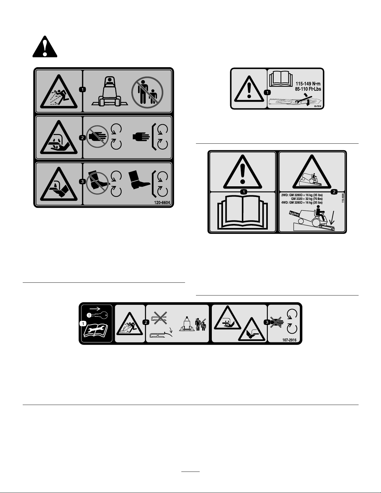
SafetyandInstructionalDecals
Safetydecalsandinstructionsareeasilyvisibletotheoperatorandarelocatednearanyareaof
potentialdanger.Replaceanydecalthatisdamagedorlost.
93-7818
1.Warning—readtheOperator'sManualforinstructionson
torquingthebladebolt/nutto115-149N-m(85-110ft-lb).
120-6604
1.Thrownobjecthazard—keepbystandersawayfromthe
machine.
2.Cutting/dismembermenthazardofhand,mower
blade—stayawayfrommovingparts,keepallguardsand
shieldsinplace.
3.Cutting/dismembermenthazardoffoot,mowerblade—stay
awayfrommovingparts,keepallguardsandshieldsin
place.
1.Removetheignitionkeyandreadthe
Operator'sManualbeforeservicingor
performingmaintenance.
2.Thrownobjecthazard—donotoperate
themowerwiththedeectorupor
removed,keepthedeectorinplace;
keepbystandersasafedistancefrom
themachine.
115-4505
1.Warning—readtheOperator'sManual.
2.Tippinghazard—lowerthecuttingunitwhendrivingdown
slopes.For2wheeldriveunits,adda16kg(35lb)rear
weighttoGM3280Dunitsanda32kg(70lb)rearweightto
GM3320units.For4wheeldrive3280Dunits,adda16
kg(35lb)rearweight.
107-2916
Model31336only
3.Cutting/dismembermenthazardof
handorfoot,mowerblade—stayaway
frommovingparts.
7
Page 8
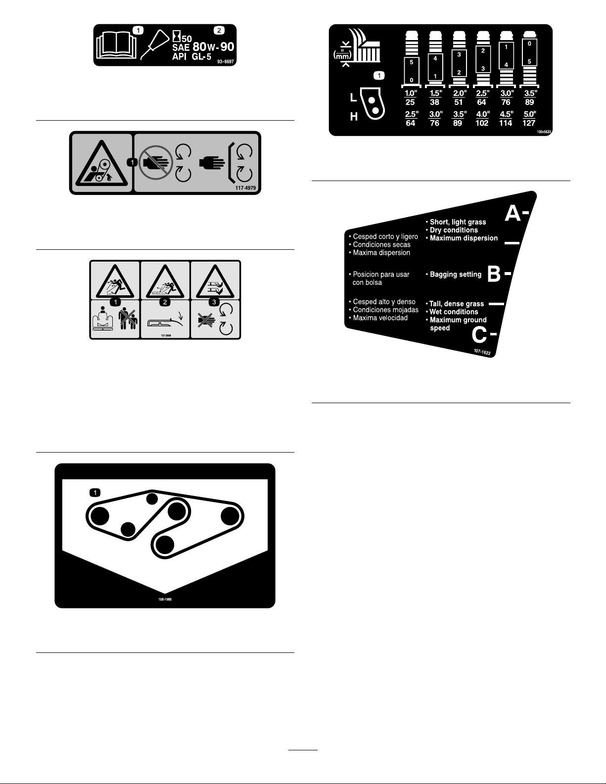
93-6697
1.ReadtheOperator's
Manual.
2.AddSAE80w-90(API
GL-5)oilevery50hours.
117–4979
1.Entanglementhazard,belt—stayawayfrommovingparts,
keepallguardsandshieldsinplace.
107-2908
Model31336only
1.Thrownobjecthazard—keepbystandersasafedistance
fromthemachine.
2.Thrownobjecthazard—donotoperatethemowerwiththe
deectoruporremoved,keepthedeectorinplace.
3.Cutting/dismembermenthazardofhandorfoot,mower
blade—stayawayfrommovingparts.
100-5622
1.Heightofcutadjustment
107-1622
Model31336only
108-1988
1.Beltrouting
8
Page 9
Setup
LooseParts
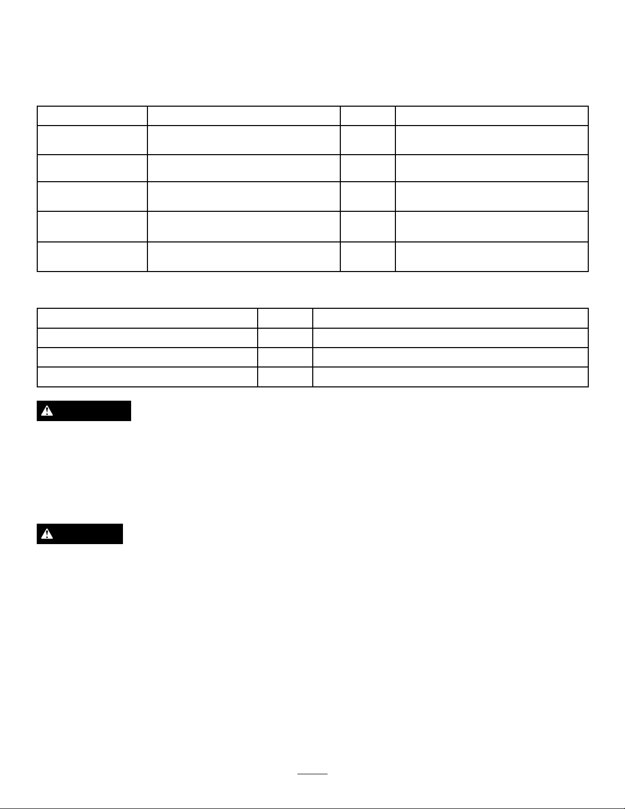
Usethechartbelowtoverifythatallpartshavebeenshipped.
ProcedureDescription
1
2
3
4
5
MediaandAdditionalParts
Description
Operator'sManual
PartsCatalog
DeclarationofConformity
Nopartsrequired
Liftarm,right
Liftarm,left
Nopartsrequired
Nopartsrequired
Nopartsrequired
Qty.
–
1
1
–
–
–
Qty.
1Reviewthematerialandsaveinanappropriateplace
1
1
Usetoreferencepartnumbers
Securethegrassdeector
Installtheliftarmstothetractionunit
Connecttheliftarmstothecuttingunit
ConnectthePTOshafttothecutting
unitgearbox.
Greasethemachine.
Use
Use
WARNING
Ifyouleavethekeyintheignitionswitch,someone
couldaccidentallystarttheengineandseriously
injureyouorotherbystanders.
Removethekeyfromtheignitionswitchbeforeyou
doanymaintenance.
DANGER
IftheengineisstartedandthePTOshaftisallowed
torotate,seriousinjurycouldresult.
DonotstarttheengineandengagethePTOswitch
whenthePTOshaftisnotconnectedtothegear
boxonthecuttingunit.
Note:Determinetheleftandrightsidesofthemachine
fromthenormaloperatingposition.
9
Page 10
Important:Ifthe72inchSideDischargeCutting
G018264
1
2
3
4
5
Unit,model31336,isbeingmountedtoamodel
30307,30308,30309,30343,30344or30345traction
unitwithaserialnumberpriorto311000301,the
CuttingUnitAlignmentKit,partnumber120–6599
mustbeinstalledtothecuttingunitpriortobeing
mountedtotractionunit.
1
SecuringtheGrassDeector
(Model31336only)
NoPartsRequired
Procedure
WARNING
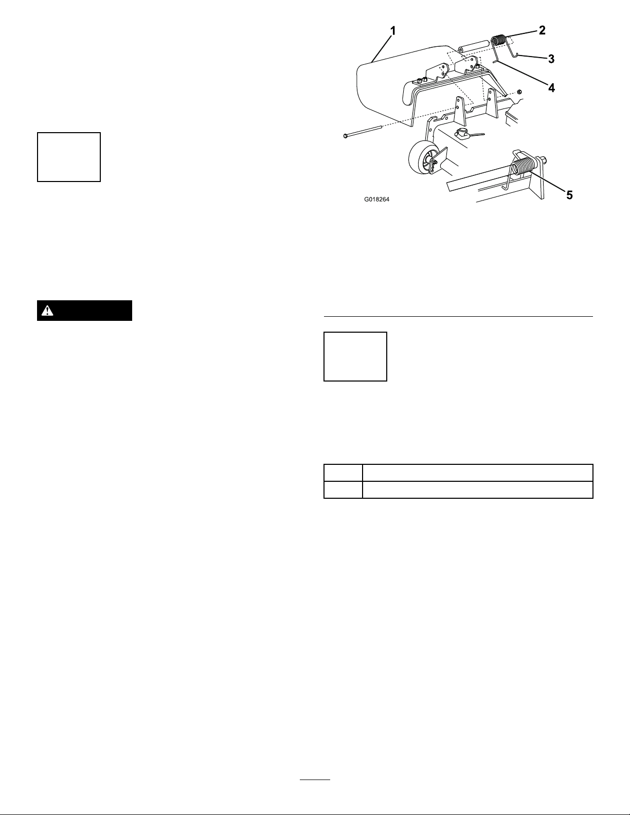
Figure2
1.GrassDeector4.Lefthandhookendof
spring,placebehinddeck
edge
2.Spring5.Springinstalled
3.Righthandhookend
ofspring,placearound
deector
Anuncovereddischargeopeningcouldallowthe
lawnmowertothrowobjectsintheoperator'sor
bystander'sdirectionandresultinseriousinjury.
Also,contactwiththebladecouldoccur.
•Neveroperatethelawnmowerunlessyouinstall
acoverplate,amulchplate,oragrasschuteand
catcher.
•Makesurethegrassdeectorisinthedown
position.
1.Removethecabletiesecuringthegrassdeectorto
thetopofthedeckandlowerthedeector.
2.PlacethelefthandJhookendofthespringaround
thedeckedge
3.PlacetherighthandJhookendofthespringaround
thegrassdeector(
Important:Thegrassdeectormustbeableto
lowerdownintoposition.Liftthedeectorup
totestthatitlowersintothefulldownposition.
Figure2).
2
InstallingtheLiftArmstothe
TractionUnit
Partsneededforthisprocedure:
1
Liftarm,right
1
Liftarm,left
Procedure
1.Ononesideofthetractionunit,loosen(donot
remove)thewheelnutssecuringthewheelandtire
assemblytothefrontwheelstuds.
2.Jackupthemachineuntilthefrontwheelisoffof
theoor.Usejackstandsorblockthemachineto
preventitfromaccidentallyfalling.
3.Removethewheelnutsandslidethewheelandtire
assemblyoffofthestuds.
4.Removetheliftarmsfromthepallet.
5.Removethepivotpinandcotterpinfromeachlift
arm.
6.Mountaliftarmtothepivotbracketwithapivotpin
andacotterpin(
thebendpositionedoutward.
10
Figure3).Mounttheliftarmwith
Page 11
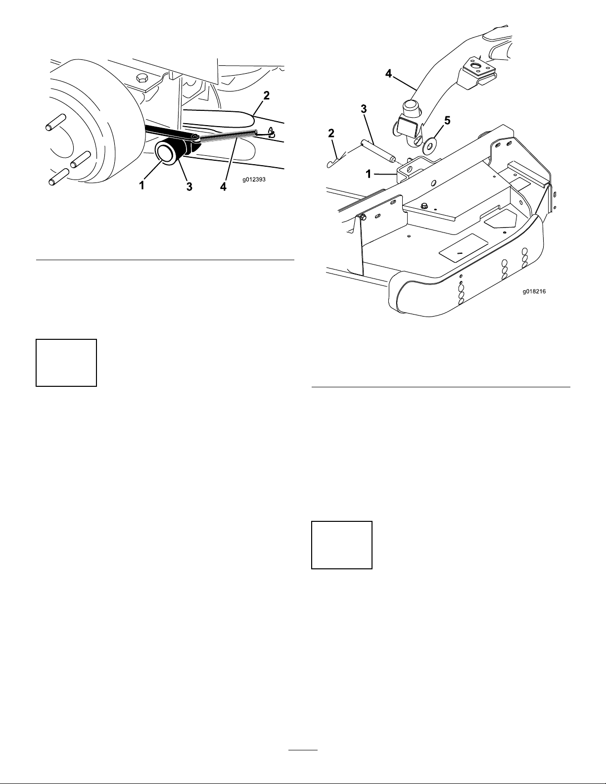
7.Hookthebrakereturnspringtothetabonthelift
g018216
1
2
3
4
5
arm(Figure3).
Figure3
1.Pivotpin4.Brakereturnspring
2.Liftarm
3.Pivotbracket
8.Installthewheelandtireassembly.T orquethewheel
nutsto75-80ft-lb(102-108N-m).
9.Repeattheprocedureontheoppositesideofthe
machine.
5.Tab
Figure4
1.Castorarmbracket4.Liftarm
2.Hairpincotter5.Thrustwasher
3.Clevispin
3
ConnectingtheLiftArmsto
theCuttingUnit
NoPartsRequired
Procedure
1.Removethe(2)thrustwashers,clevispinandhairpin
cotterfromeachcastorarmbracketonthecutting
Figure4).
unit(
2.Movethecuttingunitintopositioninfrontofthe
tractionunit.
3.PresstheliftswitchforwardtotheFloatposition.
Pushaliftarmdownuntiltheholesintheliftarm
lineupwiththeholesinthecastorarmbracket
(Figure4).
4.Securetheliftarmtothecastorarmwiththe
(2)thrustwashers,clevispinandhairpincotter.
Positionthethrustwashersbetweentheliftarm
andthecastorarmbracket(
ofcotterpinintotheslotinthecastorarmtabto
retaincotterpin.
5.Repeattheprocedureontheoppositeliftarm.
6.Startthetractionunitandraisethecuttingunit.
Figure4).Insertend
4
ConnectingthePTOShaftto
theCuttingUnitGearBox
NoPartsRequired
Procedure
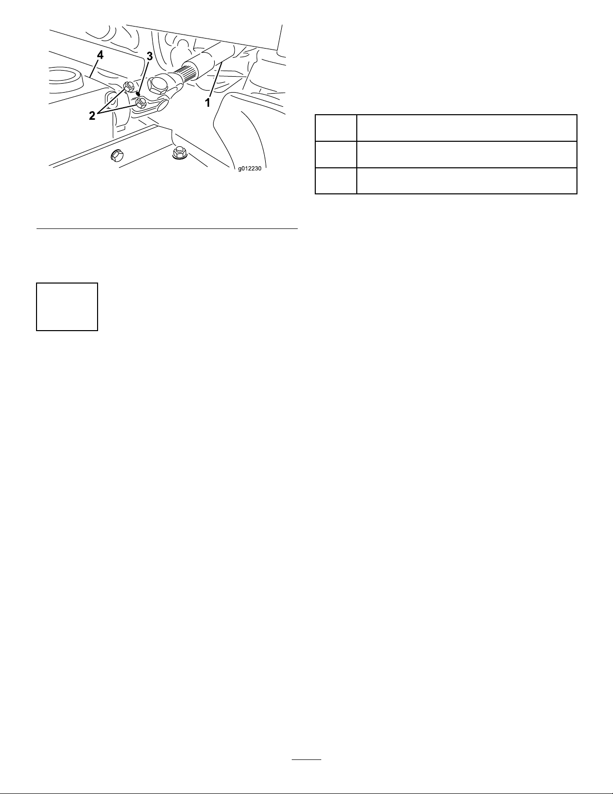
1.SlidethemalePTOshaftintothefemalePTOshaft.
Alignthemountingholesinthegearcaseinput
shaftwiththeholesinthePTOshaftandslidethem
together.
11
Page 12
ProductOverview
Specications
Note:Specicationsanddesignaresubjecttochange
withoutnotice.
Figure5
1.PTOshaft3.Gearcase
2.Boltsandlocknuts4.Rollpin
2.Securethemwitharollpin.
3.Tightentheboltsandnuts.
5
GreasingtheMachine
NoPartsRequired
Procedure
Widthof
Cut
Height
ofCut
Net
Weight
72inches(1.829m)
Adjustablefrom1to5inches(25to127mm)in1/2
inch(13mm)increments
Model31335–553lb.(251kg)
Model31336–643lb.(292kg)
Attachments/Accessories
AselectionofToroapprovedattachmentsand
accessoriesareavailableforusewiththemachineto
enhanceandexpanditscapabilities.Contactyour
AuthorizedServiceDealerorDistributororgoto
www.T oro.comforalistofallapprovedattachments
andaccessories.
Beforeoperatingthemachine,itmustbegreased
toensureproperlubricatingcharacteristics;referto
GreasingtheBearingsandBushings.Failuretoproperly
greasethemachinewillresultinprematurefailureof
criticalparts.
12
Page 13
Operation
Note:Determinetheleftandrightsidesofthe
machinefromthenormaloperatingposition.
CAUTION
Ifyouleavethekeyintheignitionswitch,someone
couldaccidentlystarttheengineandseriously
injureyouorotherbystanders.
Removethekeyfromtheignitionbeforeyoudo
anymaintenance.
CheckingtheLubricantinthe
GearBox
ServiceInterval:Every50hours
ThegearboxindesignedtooperateonSAE80–90
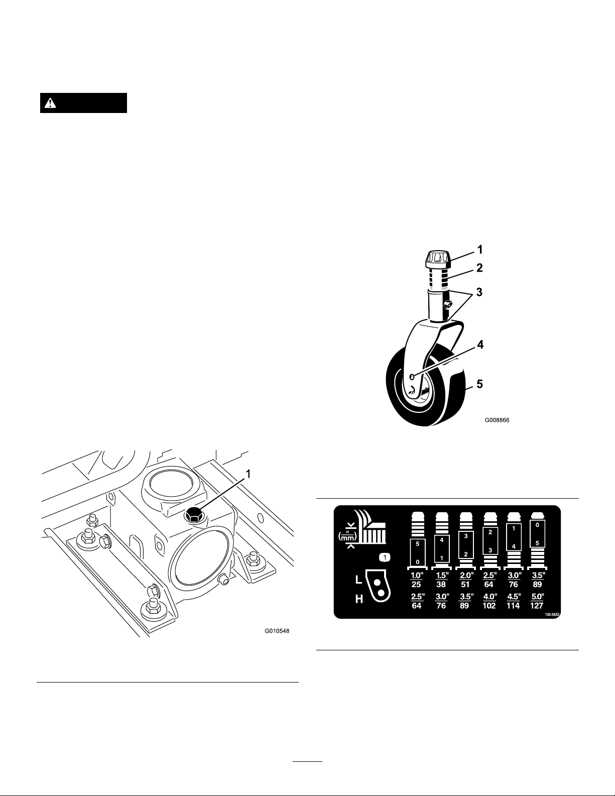
wt.gearlube.Althoughthegearboxisshippedwith
lubricantfromthefactory,checkthelevelbefore
operatingthecuttingunit.Thegearboxcapacityis12
oz.(283ml).
AdjustingtheHeight-of-Cut
Theheight-of-cutisadjustablefrom1to5inches(25
to127mm)in1/2inch(13mm)increments.Toadjust
theheight-of-cut,positionthecastorwheelaxlesinthe
upperorlowerholesofthecastorforksandaddor
removeanequalnumberofspacersfromthecastor
forks.
1.Starttheengineandraisethecuttingunitoffthe
oorsothattheheight-of-cutcanbechanged.Stop
theengineandremovethekeyafterthecuttingunit
israised.
2.Positionthecastorwheelaxlesinthesameholes
inallcastorforks.Referto
Figure9todeterminethecorrectholesforthe
setting.
Figure7,Figure8and
1.Positionthemachineandcuttingunitonalevel
surface.
2.Removethedipstick/llplugfromthetopof
thegearbox(
lubricantisbetweenthemarksonthedipstick.If
thelubricantlevelislow,addenoughlubricantuntil
thelevelisbetweenthemarks.
Figure6)andmakesurethatthe
Figure7
1.Tensioningcap4.Axlemountingholes
2.Spacers5.CastorWheel
3.Shims
Figure8
1.Dipstick/llplug
Figure6
Note:Whenoperatingin2–1/2inch(64mm)
heightofcutorhigher,theaxleboltmustbe
installedinthelowercastorforkholetoprevent
grassbuildupbetweenthewheelandthefork.
Whenoperatinginheightofcutslowerthan2–1/2
inches(64mm)andgrassbuildupisdetected,
13
Page 14
reversethemachinesdirectiontopullanyclippings
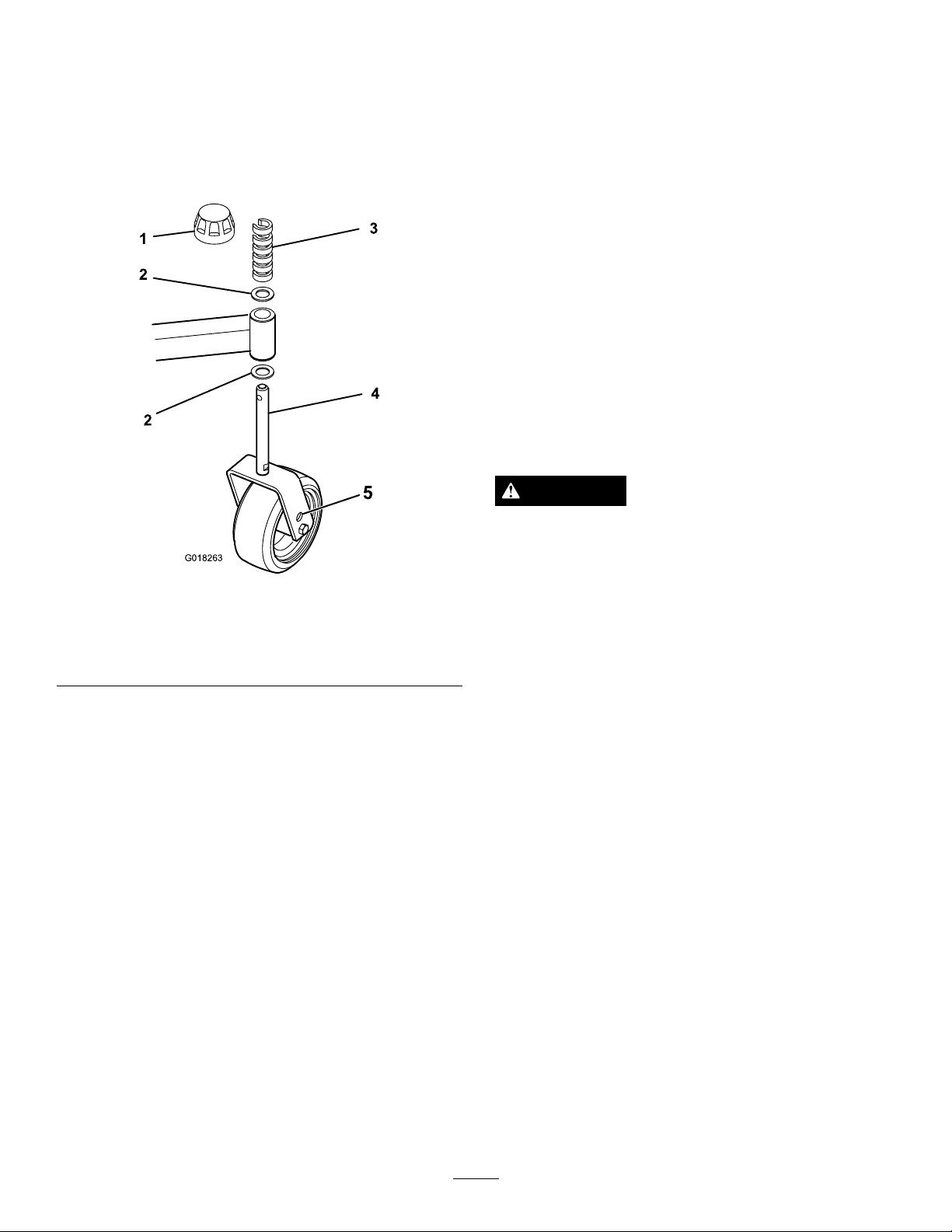
5
G018263
awayfromthewheel/forkarea.
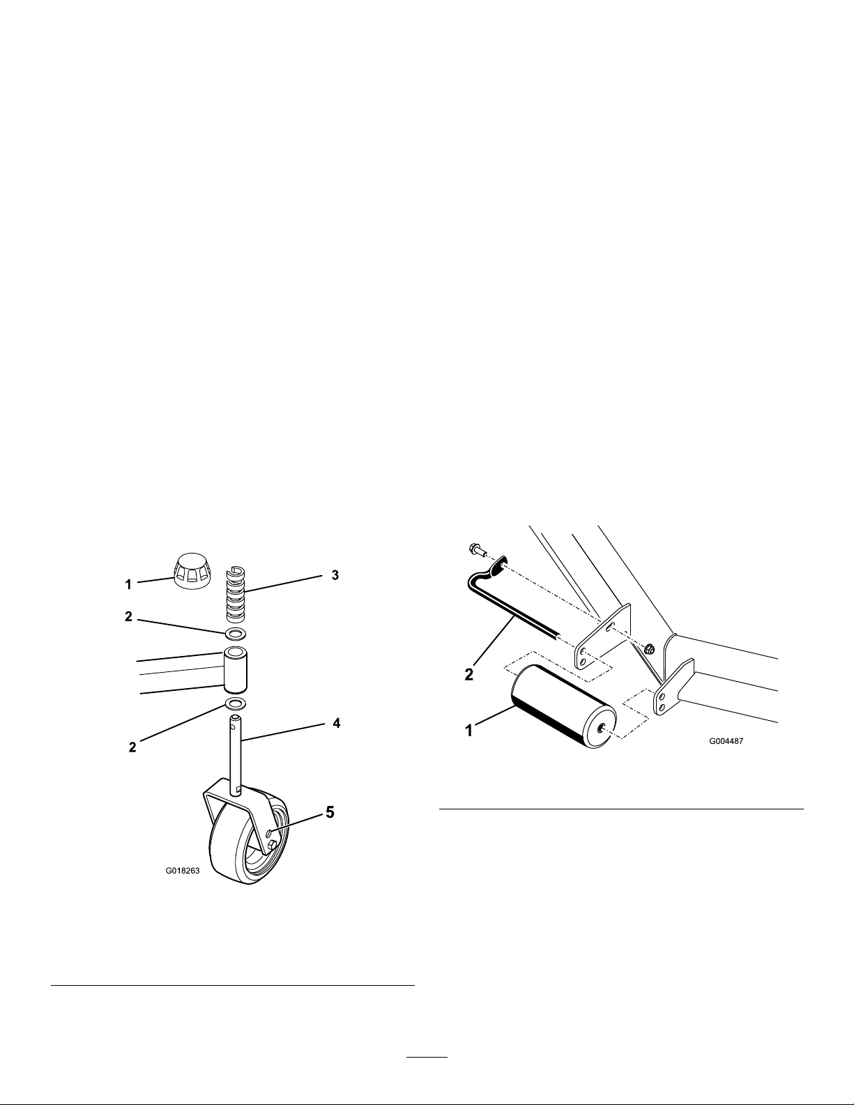
FrontCastorWheels
1.Removethetensioningcapfromthespindleshaft
Figure7)andslidethespindleoutofthecastor
(
arm.Putthe2shims(1/8inch)ontothespindle
shaftastheywereoriginallyinstalled.Theseshims
arerequiredtoachievealevelacrosstheentirewidth
ofthecuttingunits.Slidetheappropriatenumber
of1/2inchspacersontothespindleshafttogetthe
desiredheight-of-cut;thenslidethewasheronto
theshaft.
Referto
Figure8todeterminethecombinations
ofspacersforthesetting.
2.Pushthecastorspindlethroughthecastorarm.
Installtheshims(astheywereoriginallyinstalled)
andtheremainingspacersontothespindleshaft.
Installthetensioningcaptosecuretheassembly.
Note:Whenusing1inch(25mm),1-1/2inch(38
mm),oroccasionally2inch(51mm)height–of–cut,
movetheskidsandrollertothehighestholes.
RearCastorWheels
1.Removethetensioningcapfromthespindleshaft
Figure9).
(
Note:Therearcastorforkassemblydoesnotneed
toberemovedfromthecastorarmtochangethe
height-of-cut.
2.Removeoradd”C”shapedspacersatthenarrow
portionofthespindleshaft,belowthecastorarm,
togetthedesiredheight-of-cut.Makesurethatthe
shims,notthespacers,contactthetopandbottom
ofthecastorarm.
3.Installthetensioningcaptosecuretheassembly.
4.Ensurethatallfourcastorwheelsaresetatthesame
height-of-cut.
Note:Whenusing1inch(25mm),1-1/2inch(38
mm),oroccasionally2inch(51mm)height–of–cut,
movetheskidsandrollertothehighestholes.
AdjustingtheRollers
Note:Ifthecuttingunitistobeusedinthe1or1-1/2
in.(25or38mm)height-of-cutsetting,thecuttingunit
rollersmustberepositionedinthetopbracketholes.
Toadjustthefrontrollers(
1.Removethescrewandnutsecuringtherollershaft
tothedeckbracket.
Figure10).
1.Tensioningcap
2.Shims
3.“C”Shapedspacers
Figure9
4.CastorWheel
5.Axlemountingholes
Figure10
1.Roller
2.Rollershaft
2.Slidetheshaftoutofthelowerbracketholes,align
therollerwiththetopholes,andinstalltheshaft.
3.Installthescrewandnuttosecuretheassemblies.
Toadjusttherear(internal)rollers(Figure11)
14
Page 15
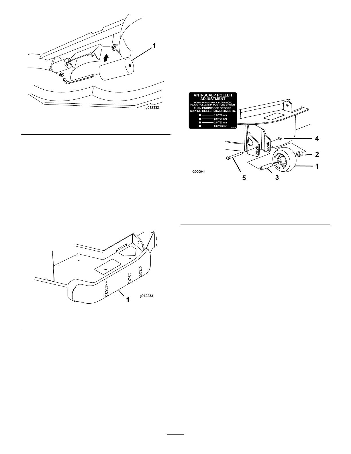
Figure11
1.Internalrollers
AdjustingtheSkids
Theskidsshouldbemountedinthelowerposition
whenoperatinginheightofcutsgreaterthan2-1/2
inches(64mm)andinthehigherpositionwhen
operatinginheightofcutslowerthan2-1/2inches(64
mm).
Adjusttheskidsbyremovingtheangeboltandnuts,
positioningthemasdesired,andinstallingthefasteners
Figure12).
(
AdjustingtheAnti-Scalp
Rollers
Wheneveryouchangetheheight-of-cut,itis
recommendedtoadjusttheheightoftheanti-scalp
rollers.
1.Afteradjustingtheheight-of-cut,adjusttherollers
byremovingtheangenut,bushing,spacer,and
Figure13).
bolt(
Figure13
1.Anti-scalproller4.FlangeNut
2.Spacer
3.Bushing
5.Bolt
2.Selectaholesotheanti-scalprollerispositionedto
thenearestcorrespondingheight-of-cutdesired.
3.Installtheangenut,bushing,spacer,andbolt.
Torqueto40-45ft-lb(54-61N-m)(
Figure13).
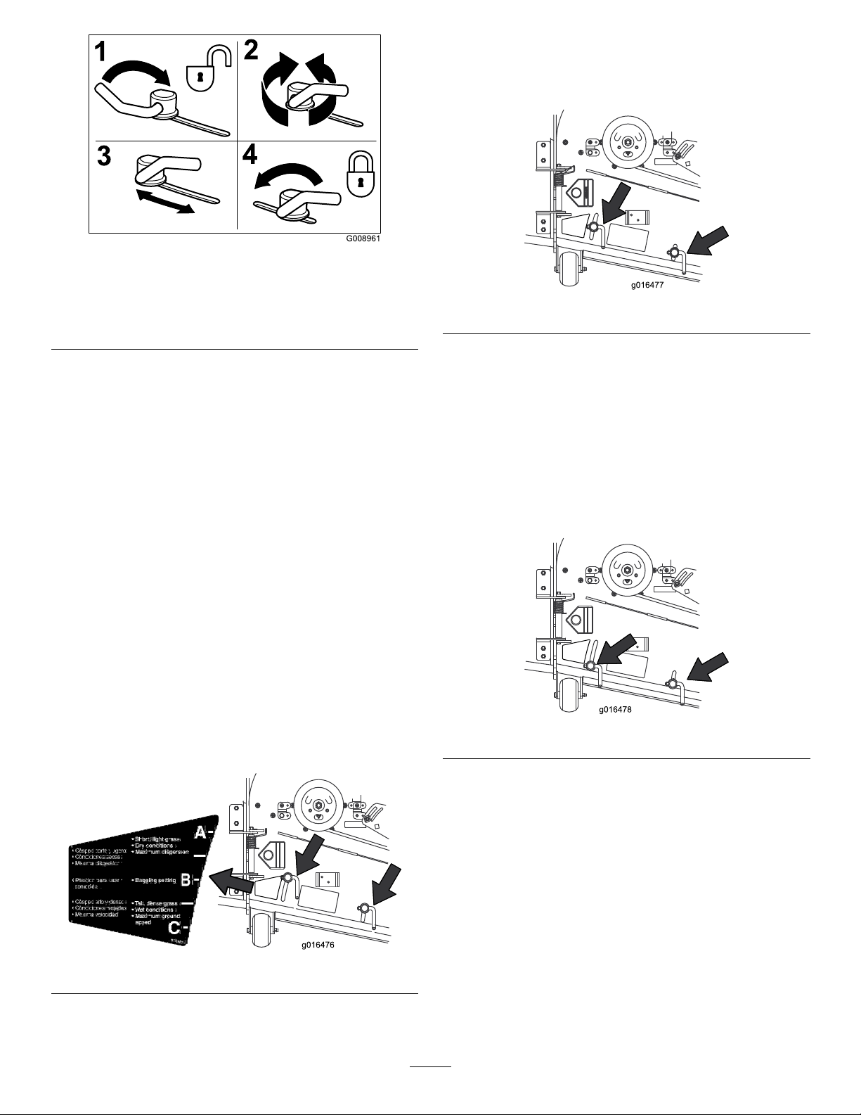
AdjustingtheFlowBafe
(Model31336only)
Figure12
1.Skid
Themowerdischargeowcanbeadjustedfordifferent
typesofmowingconditions.Positionthecamlocksand
bafetogivethebestqualityofcut.
1.Toadjustthecamlocks,swingtheleverupto
loosenthecamlock(
Figure14).
2.Adjustthebafeandcamlocksintheslotstothe
desireddischargeow .
3.Swingtheleverbackovertotightenthebafeand
camlocks(
Figure14).
4.Ifthecamlocksdonotlockthebafeintoplace
oritistootight,loosentheleverandthenrotate
thecamlock.Adjustthecamlockuntilthedesired
lockingpressureisachieved.
15
Page 16
G008961
1
2
3
4
Figure14
PositionB
Usethispositionwhenbagging.Alwaysalignitwith
thebloweropening.
1.Unlocklever
2.Rotatethecamlockto
increaseordecrease
lockingpressure
3.Positionthebafe
4.Locklever
PositioningtheFlowBafe
(Model31336only)
Thefollowingguresareonlyrecommendationsfor
use.Adjustmentswillvarybygrasstype,moisture
content,andheightofgrass.
Note:Iftheenginepowerdrawsdownandthemower
groundspeedisthesame,openupthebafe.
PositionA
Thisisthefullrearposition.Thesuggesteduseforthis
positionisafollows.
•Useforshort,lightgrassmowingconditions.
•Useindryconditions.
Figure16
PositionC
Thisisthefullopenposition.Thesuggestedusefor
thispositionisasfollows.
•Useintall,densegrassmowingconditions.
•Useinwetconditions.
•Lowerstheenginepowerconsumption.
•Allowsincreasedgroundspeedinheavyconditions.
•Forsmallergrassclippings.
•Propelsgrassclippingsfartherawayfromthe
mower.
Figure15
Figure17
AdjustingtheCuttingUnit
Pitch
Cuttingunitpitchisthedifferenceinheight-of-cut
fromthefrontofthebladeplanetothebackofthe
bladeplane.Tororecommendsabladepitchof5/16
in.(8mm).Thatisthebackofthebladeplaneis5/16
in.(8mm)higherthanthefront.
1.Positionthemachineonalevelsurfaceontheshop
oor.
2.Setthecuttingunittothedesiredheight-of-cut.
3.Rotate1bladesothatitpointsstraightforward.
16
Page 17
4.Usingashortruler,measurefromtheoortothe
5
G018263
fronttipoftheblade.Rotatethebladetiptotherear
andmeasurefromtheoortothetipoftheblade.
5.Subtractthefrontdimensionfromtherear
dimensiontocalculatethebladepitch.
6.Adjusttheshims,onthefrontorrearcastorarms,
toattaintherequiredcuttingunitpitch(Figure18).
7.Toeasemeasuringbladeplane,raisetheheightof
cuttothehighestposition;refertoAdjustingthe
HeightofCut.
8.Lowerthecuttingunitontotheatsurface.Remove
thecoversfromthetopofthecuttingunits.
9.Rotatethebladeoneachspindleuntiltheendsface
forwardandbackward.
10.Measurefromtheoortothefronttipofthe
cuttingedge.
11.Adjusttheshimsonthecastorfork(s)tomatchthe
heightofcuttodecal;refertoAdjustingtheHeight
ofCut.
UsingtheSideDischarge
(Model31336only)
Themowerhasahingedgrassdeectorthatdisperses
clippingstothesideanddowntowardtheturf.
DANGER
Figure18
1.Tensioningcap
2.Shims
3.“C”Shapedspacers
4.CastorWheel
5.Axlemountingholes
CorrectingCuttingUnit
Mismatch
Duetodifferencesingrassconditionsandthe
counterbalancesettingofthetractionunit,itisadvised
thatgrassbecutandappearancecheckedbeforeformal
cuttingisstarted.
1.Setthecuttingunittothedesiredheightofcut;
refertoAdjustingtheHeightofCut.
2.Checkandadjustfrontandreartractortirepressure
to20psi(138kPa).
3.Checkandadjustallcastortirepressuresto50psi
(345kPa).
4.Checkforbentblades;refertoCheckingforaBent
Blade.
5.Cutgrassinatestareatodetermineifallcutting
unitsarecuttingatthesameheight.
6.Ifcuttingunitadjustmentsarestillneeded,ndaat
surfaceusinga6foot(2m)orlongerstraightedge.
Withoutagrassdeector,dischargecover,or
completegrasscatcherassemblymountedin
place,youandothersareexposedtobladecontact
andthrowndebris.Contactwithrotatingmower
blade(s)andthrowndebriswillcauseinjuryor
death.
•Neverremovethegrassdeectorfromthe
mowerbecausethegrassdeectorroutes
materialdowntowardtheturf.Ifthe
grassdeectoriseverdamaged,replaceit
immediately.
•Neverputyourhandsorfeetunderthemower.
•Nevertrytoclearthedischargeareaormower
bladesunlessyoumovethepowertakeoff
(bladecontrolswitch(PTO)totheoffposition,
rotatetheignitionkeytooffandremovethekey .
•Makesurethegrassdeectorisinthedown
position.
OperatingTips
MowWhenGrassisDry
Moweitherinthelatemorningtoavoidthedew,which
causesgrassclumping,orinlateafternoontoavoidthe
damagethatcanbecausedbydirectsunlightonthe
sensitive,freshlymowedgrass.
17
Page 18

SelecttheProperHeight-of-CutSetting
toSuitConditions
Removeapproximately1in.(25mm)ornomorethan
1/3ofthegrassbladewhencutting.Inexceptionally
lushanddensegrass,youmayhavetoraisethe
height-of-cuttothenextsetting.
MowatProperIntervals
Undermostnormalconditionsyouwillneedtomow
approximatelyevery4–5days.Butremember,grass
growsatdifferentratesatdifferenttimes.Thismeans
thatinordertomaintainthesameheight-of-cut,which
isagoodpractice,youwillneedtocutmorefrequently
inearlyspring;asthegrassgrowthrateslowsinmid
summer,cutonlyevery8–10days.Ifyouareunableto
mowforanextendedperiodduetoweatherconditions
orotherreasons,mowrstwiththeheight-of-cutata
highlevel;thenmowagain2–3dayslaterwithalower
heightsetting.
AlwaysMowwithSharpBlades
Asharpbladecutscleanlyandwithouttearingor
shreddingthegrassbladeslikeadullblade.Tearingand
shreddingcausesthegrasstoturnbrownattheedges
whichimpairsgrowthandincreasessusceptibilityto
diseases.
AfterOperating
Toensureoptimumperformance,cleantheunderside
ofthemowerhousingaftereachuse.Ifresidueis
allowedtobuildupinthemowerhousing,cutting
performancewilldecrease.
CuttingUnitPitch
Werecommendabladepitchof5/16inch(8mm).A
pitchlargerthan5/16inch(8mm)willresultinless
powerrequired,largerclippings,andapoorerquality
ofcut.Apitchlessthan5/16inch(8mm)willresult
inmorepowerrequired,smallerclippingsandabetter
qualityofcut.
18
Page 19
Maintenance
RecommendedMaintenanceSchedule(s)
MaintenanceService
Interval
Aftertherst2hours
Aftertherst10hours
Beforeeachuseordaily
Every50hours
Every400hours
MaintenanceProcedure
•Tightenthecastorwheelnuts
•Tightenthecastorwheelnuts
•T orquethebladebolts
•Lubricatethecastorarmbushings
•Lubricatethecastorwheelbearings
•Checktheblades
•Checkthegearboxlubricant
•Lubricatethegreasettings
•Tightenthecastorwheelnuts
•T orquethebladebolts
•Checkthebladedrivebeltadjustment
•Cleanunderthecuttingunitbeltcovers
•Changethegearboxlubricant
CAUTION
Ifyouleavethekeyintheignitionswitch,someonecouldaccidentallystarttheengineandseriously
injureyouorotherbystanders.
Removethekeyfromtheignitionswitchbeforeyoudoanymaintenance.
19
Page 20
Lubrication
ServiceInterval:Every50hours
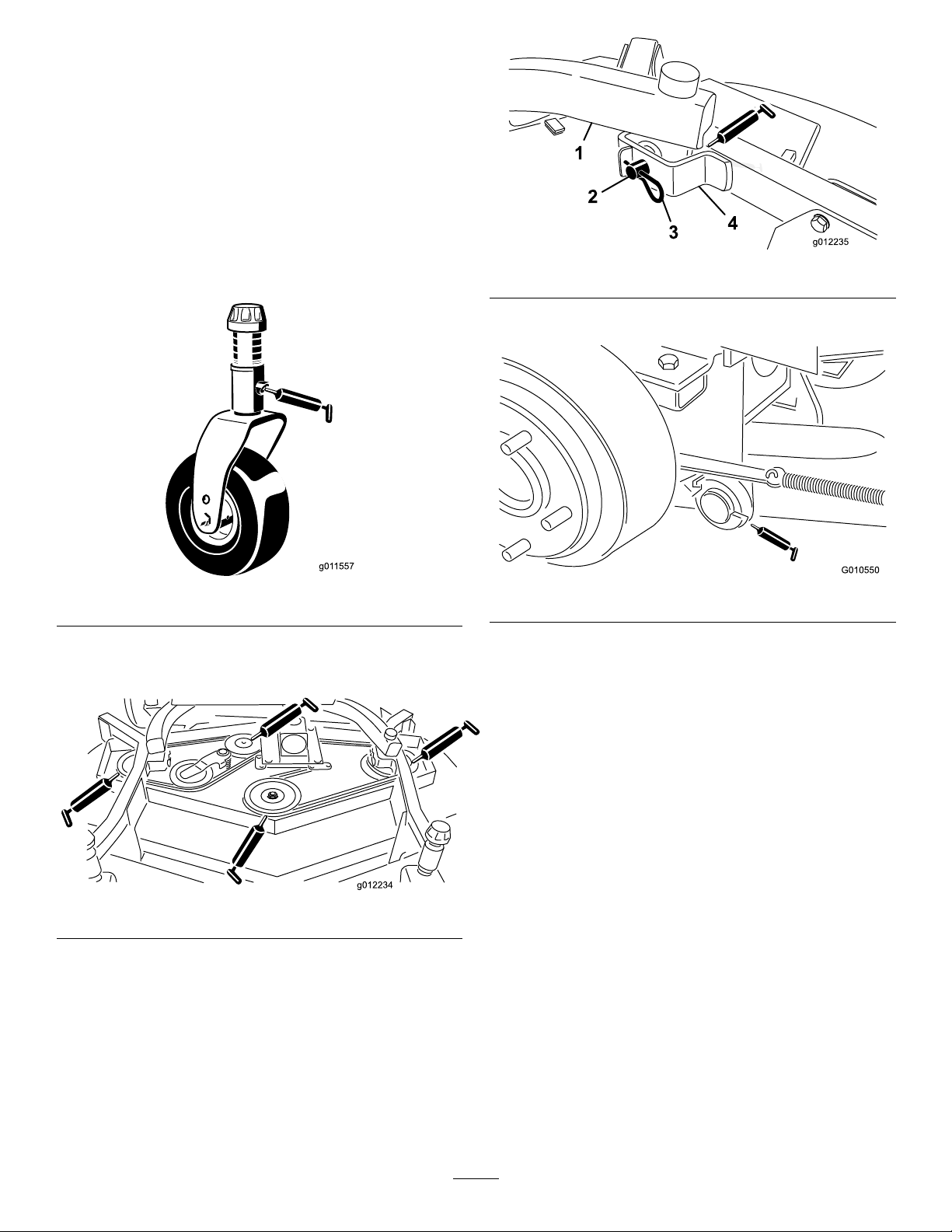
Themachinehasgreasettingsthatmustbelubricated
regularlywithNo.2GeneralPurposeLithiumBase
Grease.Ifthemachineisoperatedundernormal
conditions,lubricateallbearingsandbushingsafter
every50hoursofoperationorimmediatelyafterevery
washing.
1.Lubricatethefollowingareas:
•Castorforkshaftbushings(4)(
Figure19
•Spindleshaftbearings(3)(locatedunderthe
pulley)(Figure20)
Figure21
Figure19)
•Liftarmpivots,rear(2)(Figure22)
Figure22
2.Positionthemachineandcuttingunitonalevel
surfaceandlowerthecuttingunit.Removethe
dipstick/llplugfromthetopofthegearbox
(Figure23)andmakesurethatthelubricantis
betweenthemarksonthedipstick.Ifthelubricant
levelislow,addSAE80-90wt.gearlubeuntilthe
levelisbetweenthemarks.Thegearboxcapacity
is12oz.(283ml).
Figure20
•Idlerarmshaftbearings(Figure20)
•Liftarmpivots,front(2)(Figure21)
20
Page 21
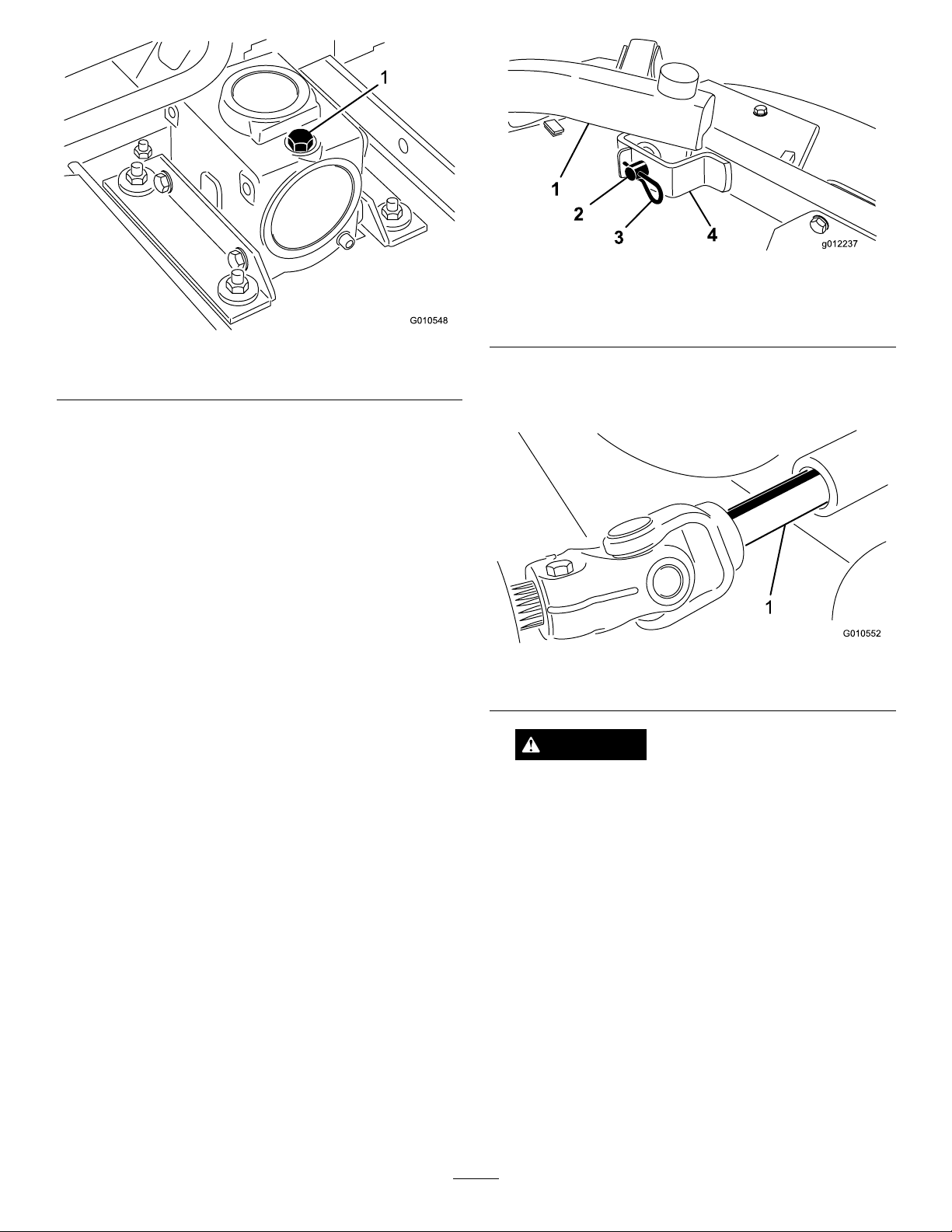
Figure24
Figure23
1.Dipstick/llplug
PreMaintenance
Important:Thefastenersonthecoversofthis
machinearedesignedtoremainonthecoverafter
removal.Loosenallofthefastenersoneachcovera
fewturnssothatthecoverisloosebutstillattached,
thengobackandloosenthemuntilthecover
comesfree.Thiswillpreventyoufromaccidentally
strippingtheboltsfreeoftheretainers.
SeparatingtheCuttingUnit
fromtheTractionUnit
1.Positionthemachineonlevelsurface,lowerthe
cuttingunittotheoor,movetheliftlevertothe
Floatposition,shuttheengineoff,andengagethe
parkingbrake.
2.Removethehairpincottersandclevispinssecuring
theliftarmstothecastorarmbrackets(
Figure24).
1.Liftarm
2.Clevispin4.Castorarmbracket
3.Rollthecuttingunitawayfromthetractionunit,
separatingthemaleandfemalesectionsofthePTO
Figure25).
shaft(
1.PTOshaft
3.Hairpincotter
Figure25
DANGER
IftheengineisstartedandthePTOshaftis
allowedtorotate,seriousinjurycouldresult.
DonotstarttheengineandengagethePTO
leverwhenthePTOshaftisnotconnectedto
thegearboxonthecuttingunit.
MountingtheCuttingUnitto
theTractionUnit
1.Positionthemachineonalevelsurfaceandshutthe
engineoff.
2.Movethecuttingunitintopositioninfrontofthe
tractionunit.
3.SlidethemalePTOshaftintothefemalePTOshaft
(Figure25).
4.PresstheliftswitchforwardtotheFloatposition.
Pushaliftarmdownuntiltheholesintheliftarm
21
Page 22
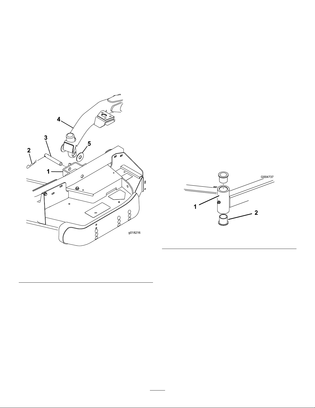
lineupwiththeholesinthecastorarmbracketand
g018216
1
2
3
4
5
theheightofcutrodcanbeinsertedintotheliftarm
pads(Figure26).
ServicingtheBushingsinthe
CastorArms
5.Securetheliftarmtothecastorarmwith(2)thrust
washers,aclevispinandahairpincotter.Position
thethrustwashersbetweentheliftarmandthecastor
armbracket(
Figure26).Insertendofcotterpininto
theslotinthecastorarmtabtoretaincotterpin.
6.Repeattheprocedureontheoppositeliftarm.
7.Startthetractionunitandraisethecuttingunit.
Thecastorarmshavebushingspressedintothetopand
bottomofthetubeandaftermanyhoursofoperation,
thebushingswillwear.Tocheckthebushings,movethe
castorforkbackandforthandfromsidetoside.Ifthe
castorspindleislooseinsidethebushings,thebushings
arewornandmustbereplaced.
1.Raisethecuttingunitsothatthewheelsareoffof
theoor.Blockthecuttingunitsothatitcannot
accidentallyfall.
2.Removethetensioningcap,spacer(s),andthrust
washerfromthetopofthecastorspindle.
3.Pullthecastorspindleoutofthemountingtube.
Allowthethrustwasherandspacer(s)toremainon
thebottomofthespindle.
4.Insertapinpunchintothetoporbottomofthe
mountingtubeanddrivethebushingoutofthetube
Figure27).Alsodrivetheotherbushingoutofthe
(
tube.Cleantheinsideofthetubestoremovedirt.
Figure27
2.Bushings
Figure26
1.Castorarmbracket4.Liftarm
2.Hairpincotter5.Thrustwasher
3.Clevispin
1.Castorarmtube
5.Applygreasetotheinsideandoutsideofthenew
bushings.Usingahammerandatplate,drivethe
bushingsintothemountingtube.
6.Inspectthecastorspindleforwearandreplaceitif
damaged.
7.Pushthecastorspindlethroughthebushingsand
mountingtube.Slidethethrustwasherandspacer(s)
ontothespindle.Installthetensioningcaponthe
castorspindletoretainallpartsinplace.
ServicingtheCastorWheels
andBearings
1.Removethelocknutfromtheboltholdingthecastor
wheelassemblybetweenthecastorfork(Figure28).
Graspthecastorwheelandslidetheboltoutofthe
forkorpivotarm.
22
Page 23
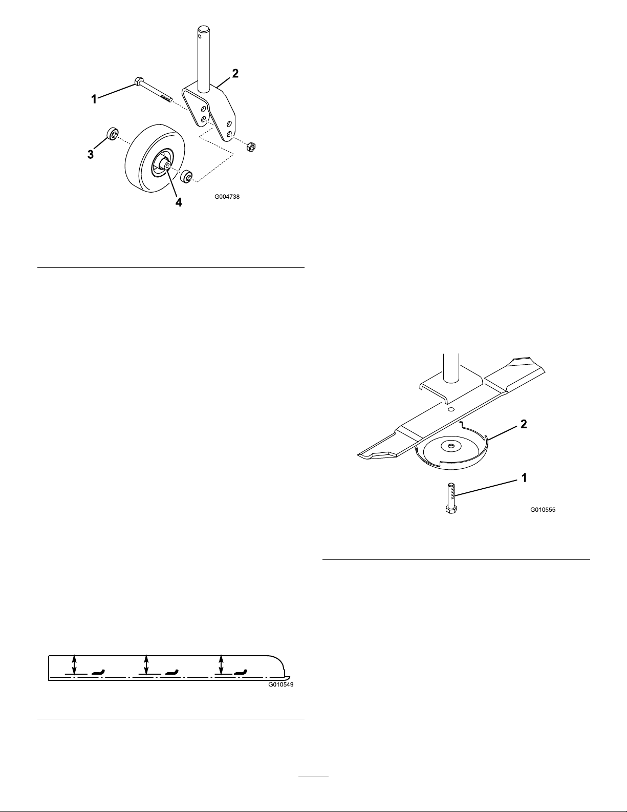
Figure28
G010549
G010555
1
2
1.Castorwheel3.Bearing(2)
2.Castorfork
4.Bearingspacer
2.Removethebearingfromthewheelhubandallow
thebearingspacertofallout(Figure28).Remove
thebearingfromtheoppositesideofthewheelhub.
3.Checkthebearings,spacer,andinsideofthewheel
hubforwear.Replaceanydamagedparts.
ofthebladeatthesamepositionasinstep2The
differencebetweenthedimensionsobtainedin
steps2and3mustnotexceed1/8inch(3mm).If
thedimensionexceeds1/8inch(3mm),replace
thebladebecauseitisbent;refertoRemovingthe
CuttingBlade.
RemovingandInstallingthe
Blade(s)
Theblademustbereplacedifasolidobjectishit,the
bladeisout-of-balance,worn,orbent.Alwaysuse
genuineTororeplacementbladestoensuresafetyand
optimumperformance.Neverusebladesmadebyother
manufacturersbecausetheycouldbedangerous.
1.Raisethecuttingunittothehighestposition,engage
theparkingbrake,stoptheengine,andremovethe
ignitionkey.Blockthecuttingunittopreventitfrom
accidentallyfalling.
2.Grasptheendofthebladeusingaragorthickly
paddedglove.Removethebladebolt,anti-scalpcup,
andbladefromthespindleshaft(
Figure30).
4.Toassemblethecastorwheel,pushthebearinginto
thewheelhub.Wheninstallingthebearings,press
ontheouterraceofthebearing.
5.Slidethebearingspacerintothewheelhub.Pushthe
otherbearingintotheopenendofthewheelhubto
captivatethebearingspacerinsidethewheelhub.
6.Installthecastorwheelassemblybetweenthecastor
forkandsecureitinplacewiththeboltandlocknut.
CheckingforaBentBlade
1.Positionthemachineonalevelsurface.Raisethe
cuttingunit,engagetheparkingbrake,putthe
tractionpedalinneutral,putthePTOleverin
theOffposition,stoptheengine,andremovethe
ignitionkey.Blockthecuttingunittopreventitfrom
accidentallyfalling.
2.Rotatethebladeuntiltheendsfaceforwardand
backward.Measurefromtheinsideofthecutting
unittothecuttingedgeatthefrontoftheblade
(Figure29),andrememberthisdimension.
Figure30
1.Bladebolt2.Anti-scalpcup
3.Installtheblade-sailfacingtowardthecutting
unit-withtheanti-scalpcupandbladebolt.Tighten
thebladeboltto85-110ft-lb(115-149N-m).
Important:Thecurvedpartoftheblademust
bepointingtowardtheinsideofthecuttingunit
toensurepropercutting.
Figure29
3.Rotatetheoppositeendofthebladeforward.
Measurebetweenthecuttingunitandcuttingedge
23
Page 24
InspectingandSharpeningthe
Blade(s)
ServiceInterval:Beforeeachuseordaily
Every50hours
DANGER
Awornordamagedbladecanbreak,andapiece
ofthebladecouldbethrownintotheoperator's
orbystander'sarea,resultinginseriouspersonal
injuryordeath.
•Inspectthebladeperiodicallyforwearor
damage.
•Donottrytostraightenabladethatisbent.
•Neverweldabrokenorcrackedblade.
•Replaceawornordamagedbladewitha
newT orobladetoensurecontinuedsafety
certicationoftheproduct.
Twoareasmustbeconsideredwhencheckingand
servicingthecuttingblade:thesailandthecuttingedge.
Bothcuttingedgesandthesail,whichistheturnedup
portionoppositethecuttingedge,contributetoagood
quality-of-cut.Thesailisimportantbecauseitpullsgrass
upstraight,therebyproducinganevencut.However,
thesailwillgraduallyweardownduringoperation,and
thisconditionisnormal.Asthesailwearsdown,the
quality-of-cutwilldegradesomewhat,althoughthe
cuttingedgesaresharp.Thecuttingedgeoftheblade
mustbesharpsothatthegrassiscutratherthantorn.
Adullcuttingedgeisevidentwhenthetipsofthegrass
appearbrownandshredded.Sharpenthecuttingedges
tocorrectthiscondition.
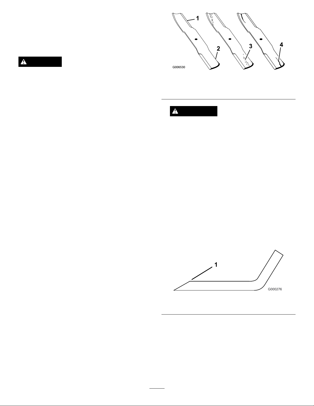
Figure31
1.Cuttingedge3.Wear/slotforming
2.Curvedarea/sail4.Crack
WARNING
Ifthebladeisallowedtowear,aslotwillform
betweenthesailandatpartoftheblade
Figure31).Eventually,apieceoftheblademay
(
breakoffandbethrownfromunderthehousing,
possiblyresultinginseriousinjurytoyourself
orbystanders.
•Inspectthebladeperiodicallyforwearor
damage.
•Replaceawornordamagedbladewitha
newTorobladetoensurecontinuedsafety
certicationoftheproduct.
3.Examinethecuttingedgesofallblades.Sharpenthe
cuttingedgesiftheyaredullornicked.Sharpenonly
thetopsideofthecuttingedgeandmaintainthe
originalcuttingangletoensuresharpness(Figure32).
Thebladewillremainbalancedifthesameamount
ofmetalisremovedfrombothcuttingedges.
1.Positionthemachineonalevelsurface.Raisethe
cuttingunit,engagetheparkingbrake,putthe
tractionpedalinneutral,putthePTOleverin
theOffposition,stoptheengine,andremovethe
ignitionkey .
2.Examinethecuttingendsofthebladecarefully,
especiallywheretheatandcurvedpartsofthe
blademeet(
materialcanwearawaythemetalthatconnects
theatandcurvedpartsoftheblade,checkthe
bladebeforeusingthemachine.Ifwearisnoticed
(Figure31),replacetheblade;refertoRemovingthe
CuttingBlade.
Figure31).Sincesandandabrasive
Figure32
1.Sharpenatoriginalangle
Note:Removethebladesandsharpenthemona
grinder;refertoRemovingtheCuttingBlades.After
sharpeningthecuttingedges,installthebladewith
theanti-scalpcupandbladebolt.Thebladesails
mustbeontopoftheblade.Tightenthebladebolt
to85-110ft-lb(115-149N-m).
24
Page 25
CheckingandCorrecting
ReplacingtheDriveBelt
MismatchofBlades
Ifthereismismatchbetweentheblades,thegrasswill
appearstreakedwhenitiscut.Thisproblemcanbe
correctedbymakingsurethatthebladesarestraightand
allofthebladesarecuttingonthesameplane.
1.Usinga3foot(1meter)longcarpenterslevel,nd
alevelsurfaceontheshopoor.
2.Raisetheheight-of-cuttothehighestposition;refer
toAdjustingtheHeight-of-Cut.
3.Lowerthecuttingunitontotheatsurface.Remove
thecoversfromthetopofthecuttingunit.
4.Rotatethebladesuntiltheendsfaceforwardand
backward.Measurefromtheoortothefronttipof
thecuttingedge.Rememberthisdimension.Then
rotatethesamebladesothattheoppositeendis
forward,andmeasureagain.Thedifferencebetween
thedimensionsmustnotexceed1/8inch(3mm).
Ifthedimensionexceeds1/8inch(3mm),replace
thebladebecauseitisbent.Makesuretomeasure
alloftheblades.
Thebladedrivebelt,tensionedbythespringloaded
idlerpulley,isverydurable.However,aftermanyhours
ofuse,thebeltwillshowsignsofwear.Signsofaworn
beltare:squealingwhenbeltisrotating,bladesslipping
whencuttinggrass,frayededges,burnmarksandcracks.
Replacethebeltifanyoftheseconditionsareevident.
1.Lowerthecuttingunittotheshopoor.Remove
thebeltcoversfromthetopofthecuttingunitand
setthecoversaside.
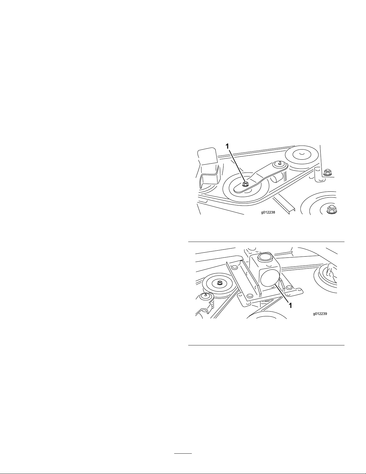
2.Usingatorquewrenchorsimilartool,movetheidler
pulley(
thebelttensionandallowthebelttobeslippedoff
thegearboxpulley(Figure34).
Figure33)awayfromthedrivebelttorelease
5.Comparethemeasurementsoftheouterbladeswith
thecenterblade.Thecenterblademustnotbemore
than3/8in.(10mm)lowerthantheouterblades.If
thecenterbladeismorethan3/8in.(10mm)lower
thantheouterblades,proceedtostep
shimsbetweenthespindlehousingandthebottom
ofthecuttingunit.
6.Removethebolts,atwashers,lockwashers,and
nutsfromtheouterspindleintheareawherethe
shimsmustbeadded.Toraiseorlowertheblade,
addashim,PartNo.3256-24,betweenthespindle
housingandthebottomofthecuttingunit.Continue
tocheckthealignmentofthebladesandaddshims
untilthetipsofthebladesarewithintherequired
dimension.
Important:Donotusemorethanthreeshimsat
anyoneholelocation.Usedecreasingnumbers
ofshimsinadjacentholesifmorethanoneshim
isaddedtoanyoneholelocation.
7.Installthebeltcovers.
6andadd
Figure33
1.Idlerpulley
Figure34
1.Gearbox
3.Removetheoldbeltfromaroundthespindlepulleys
andidlerpulley.
4.Routethenewbeltaroundthespindlepulleysand
idlerpulleyassemblyasshowninFigure35.
25
Page 26
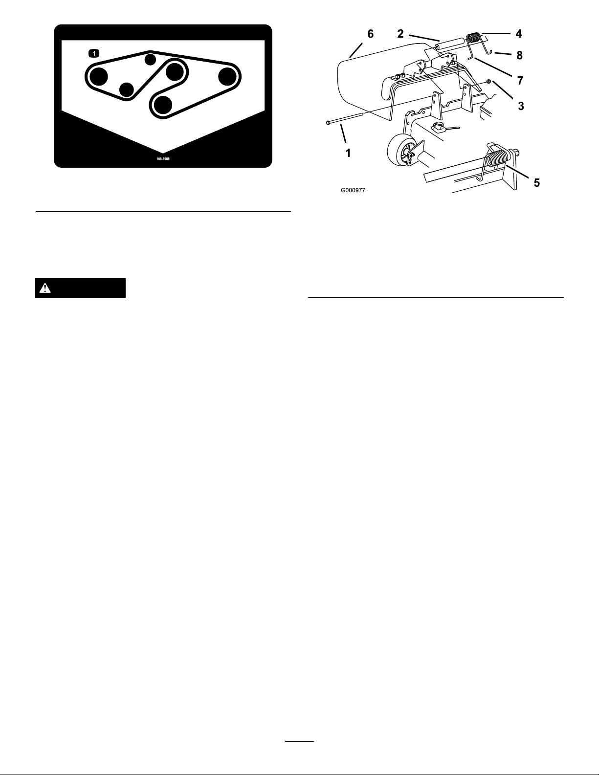
Figure35
1.Beltrouting
5.Installthebeltcovers.
ReplacingtheGrassDeector
WARNING
Anuncovereddischargeopeningcouldallowthe
lawnmowertothrowobjectsintheoperator'sor
bystander'sdirectionandresultinseriousinjury.
Also,contactwiththebladecouldoccur.
•Neveroperatethelawnmowerunlessyouinstall
acoverplate,amulchplate,oragrasschuteand
catcher.
•Makesurethegrassdeectorisinthedown
position.
1.Removethelocknut,bolt,springandspacerholding
thedeectortothepivotbrackets(
Removethedamagedorworngrassdeector.
Figure36).
Figure36
1.Bolt
2.Spacer6.GrassDeector
3.Locknut
4.Spring8.Jhookendofspring
5.Springinstalled
7.Lendofspring,place
behinddeckedgebefore
installingbolt
2.Placethespacerandspringontograssdeector.
PlacetheLendofspringbehinddeckedge.
Note:MakesuretheLendofthespringisinstalled
behindthedeckedgebeforeinstallingtheboltas
shownin
Figure36.
3.Installtheboltandnut.PlacetheJhookendofthe
springaroundthegrassdeector(Figure36).
Important:Thegrassdeectormustbeableto
lowerdownintoposition.Liftthedeectorup
totestthatitlowersintothefulldownposition.
26
Page 27

Notes:
27
Page 28

TheT oroTotalCoverageGuarantee
ALimitedWarranty
ConditionsandProductsCovered
TheT oroCompanyanditsafliate,T oroWarrantyCompany,pursuant
toanagreementbetweenthem,jointlywarrantyourT oroCommercial
product(“Product”)tobefreefromdefectsinmaterialsorworkmanship
fortwoyearsor1500operationalhours*,whicheveroccursrst.This
warrantyisapplicabletoallproductswiththeexceptionofAerators
(refertoseparatewarrantystatementsfortheseproducts).Wherea
warrantableconditionexists,wewillrepairtheProductatnocosttoyou
includingdiagnostics,labor,parts,andtransportation.Thiswarranty
beginsonthedatetheProductisdeliveredtotheoriginalretailpurchaser.
*Productequippedwithanhourmeter.
InstructionsforObtainingWarrantyService
YouareresponsiblefornotifyingtheCommercialProductsDistributoror
AuthorizedCommercialProductsDealerfromwhomyoupurchasedthe
Productassoonasyoubelieveawarrantableconditionexists.Ifyouneed
helplocatingaCommercialProductsDistributororAuthorizedDealer ,or
ifyouhavequestionsregardingyourwarrantyrightsorresponsibilities,
youmaycontactusat:
ToroCommercialProductsServiceDepartment
ToroWarrantyCompany
811 1LyndaleAvenueSouth
Bloomington,MN55420-1196
952–888–8801or800–952–2740
E-mail:[email protected]
OwnerResponsibilities
AstheProductowner,youareresponsibleforrequiredmaintenance
andadjustmentsstatedinyourOperator'sManual.Failuretoperform
requiredmaintenanceandadjustmentscanbegroundsfordisallowinga
warrantyclaim.
ItemsandConditionsNotCovered
Notallproductfailuresormalfunctionsthatoccurduringthewarranty
periodaredefectsinmaterialsorworkmanship.Thiswarrantydoesnot
coverthefollowing:
•Productfailureswhichresultfromtheuseofnon-T ororeplacement
parts,orfrominstallationanduseofadd-on,ormodiednon-T oro
brandedaccessoriesandproducts.Aseparatewarrantymaybe
providedbythemanufactureroftheseitems.
•Productfailureswhichresultfromfailuretoperformrecommended
maintenanceand/oradjustments.Failuretoproperlymaintainyour
ToroproductpertheRecommendedMaintenancelistedinthe
Operator’sManualcanresultinclaimsforwarrantybeingdenied.
•ProductfailureswhichresultfromoperatingtheProductinan
abusive,negligent,orrecklessmanner.
•Partssubjecttoconsumptionthroughuseunlessfoundtobe
defective.Examplesofpartswhichareconsumed,orusedup,
duringnormalProductoperationinclude,butarenotlimitedto,brake
padsandlinings,clutchlinings,blades,reels,rollersandbearings
(sealedorgreasable),bedknives,sparkplugs,castorwheelsand
bearings,tires,lters,belts,andcertainsprayercomponentssuchas
diaphragms,nozzles,andcheckvalves,etc.
•Failurescausedbyoutsideinuence.Conditionsconsideredtobe
outsideinuenceinclude,butarenotlimitedto,weather,storage
practices,contamination,useofunapprovedfuels,coolants,
lubricants,additives,fertilizers,water,orchemicals,etc.
•Failureorperformanceissuesduetotheuseoffuels(e.g.gasoline,
diesel,orbiodiesel)thatdonotconformtotheirrespectiveindustry
standards.
•Normalnoise,vibration,wearandtear,anddeterioration.
•Normal“wearandtear”includes,butisnotlimitedto,damageto
seatsduetowearorabrasion,wornpaintedsurfaces,scratched
decalsorwindows,etc.
Parts
Partsscheduledforreplacementasrequiredmaintenancearewarranted
fortheperiodoftimeuptothescheduledreplacementtimeforthatpart.
Partsreplacedunderthiswarrantyarecoveredforthedurationofthe
originalproductwarrantyandbecomethepropertyofToro.T orowill
makethenaldecisionwhethertorepairanyexistingpartorassemblyor
replaceit.T oromayuseremanufacturedpartsforwarrantyrepairs.
DeepCycleandLithium-IonBatteryWarranty:
DeepcycleandLithium-Ionbatterieshaveaspeciedtotalnumberof
kilowatt-hourstheycandeliverduringtheirlifetime.Operating,recharging,
andmaintenancetechniquescanextendorreducetotalbatterylife.Asthe
batteriesinthisproductareconsumed,theamountofusefulworkbetween
chargingintervalswillslowlydecreaseuntilthebatteryiscompletelyworn
out.Replacementofwornoutbatteries,duetonormalconsumption,
istheresponsibilityoftheproductowner.Batteryreplacementmaybe
requiredduringthenormalproductwarrantyperiodatowner’sexpense.
Note:(Lithium-Ionbatteryonly):ALithium-Ionbatteryhasapartonly
proratedwarrantybeginningyear3throughyear5basedonthetime
inserviceandkilowatthoursused.RefertotheOperator'sManualfor
additionalinformation.
MaintenanceisatOwner’sExpense
Enginetune-up,lubrication,cleaningandpolishing,replacementoflters,
coolant,andcompletingrecommendedmaintenancearesomeofthe
normalservicesToroproductsrequirethatareattheowner’sexpense.
GeneralConditions
RepairbyanAuthorizedT oroDistributororDealerisyoursoleremedy
underthiswarranty .
NeitherTheToroCompanynorToroWarrantyCompanyisliablefor
indirect,incidentalorconsequentialdamagesinconnectionwiththe
useoftheToroProductscoveredbythiswarranty,includingany
costorexpenseofprovidingsubstituteequipmentorserviceduring
reasonableperiodsofmalfunctionornon-usependingcompletion
ofrepairsunderthiswarranty .ExceptfortheEmissionswarranty
referencedbelow,ifapplicable,thereisnootherexpresswarranty.
Allimpliedwarrantiesofmerchantabilityandtnessforuseare
limitedtothedurationofthisexpresswarranty.
Somestatesdonotallowexclusionsofincidentalorconsequential
damages,orlimitationsonhowlonganimpliedwarrantylasts,sothe
aboveexclusionsandlimitationsmaynotapplytoyou.Thiswarranty
givesyouspeciclegalrights,andyoumayalsohaveotherrightswhich
varyfromstatetostate.
Noteregardingenginewarranty:
TheEmissionsControlSystemonyourProductmaybecoveredby
aseparatewarrantymeetingrequirementsestablishedbytheU.S.
EnvironmentalProtectionAgency(EPA)and/ortheCaliforniaAir
ResourcesBoard(CARB).Thehourlimitationssetforthabovedonot
applytotheEmissionsControlSystemWarranty.RefertotheEngine
EmissionControlWarrantyStatementsuppliedwithyourproductor
containedintheenginemanufacturer’sdocumentationfordetails
CountriesOtherthantheUnitedStatesorCanada
CustomerswhohavepurchasedT oroproductsexportedfromtheUnitedStatesorCanadashouldcontacttheirToroDistributor(Dealer)toobtain
guaranteepoliciesforyourcountry,province,orstate.IfforanyreasonyouaredissatisedwithyourDistributor'sserviceorhavedifcultyobtaining
guaranteeinformation,contacttheToroimporter.
374-0253RevB
 Loading...