

Toro 31236, Groundsmaster 360, 31230 Operator's Manual

FormNo.3403-595RevA
Groundsmaster
®
3604-Wheel
DriveMulti-PurposeMachine
withCab
ModelNo.31236—SerialNo.316000001andUp
Registeratwww.T oro.com.
OriginalInstructions(EN)
*3403-595*A
ThisproductcomplieswithallrelevantEuropeandirectives;
fordetails,pleaseseetheseparateproductspecicDeclaration
ofConformity(DOC)sheet.
WARNING
CALIFORNIA
Proposition65Warning
Thisproductcontainsachemicalorchemicals
knowntotheStateofCaliforniatocausecancer,
birthdefects,orreproductiveharm.
Dieselengineexhaustandsomeofits
constituentsareknowntotheStateof
Californiatocausecancer,birthdefects,
andotherreproductiveharm.
ItisaviolationofCaliforniaPublicResourceCode
Section4442or4443touseoroperatetheengineonany
forest-covered,brush-covered,orgrass-coveredlandunless
theengineisequippedwithasparkarrester,asdenedin
Section4442,maintainedineffectiveworkingorderorthe
engineisconstructed,equipped,andmaintainedforthe
preventionofre.
Figure1
1.Modelandserialnumberlocation
ModelNo.
SerialNo.
Thismanualidentiespotentialhazardsandhassafety
messagesidentiedbythesafety-alertsymbol(Figure2),
whichsignalsahazardthatmaycauseseriousinjuryordeath
ifyoudonotfollowtherecommendedprecautions.
Introduction
Thismachineisaride-on,multi-purposemachineintended
tobeusedbyprofessional,hiredoperatorsincommercial
applications.Itisprimarilydesignedformaintaininggrass
onwell-maintainedlawnsinparks,sportselds,andon
commercialgrounds.Itisnotdesignedforcuttingbrush,
mowinggrassandothergrowthalongsidehighways,orfor
agriculturaluses.
Readthisinformationcarefullytolearnhowtooperateand
maintainyourproductproperlyandtoavoidinjuryand
productdamage.Youareresponsibleforoperatingthe
productproperlyandsafely.
YoumaycontactTorodirectlyatwww .Toro.comforproduct
safetyandoperationtrainingmaterials,accessoryinformation,
helpndingadealer,ortoregisteryourproduct.
Wheneveryouneedservice,genuineT oroparts,oradditional
information,contactanAuthorizedServiceDealerorToro
CustomerServiceandhavethemodelandserialnumbersof
yourproductready.Figure1identiesthelocationofthe
modelandserialnumbersontheproduct.Writethenumbers
inthespaceprovided.
Figure2
1.Safety-alertsymbol
Thismanualuses2wordstohighlightinformation.
Importantcallsattentiontospecialmechanicalinformation
andNoteemphasizesgeneralinformationworthyofspecial
attention.
©2016—TheToro®Company
8111LyndaleAvenueSouth
Bloomington,MN55420
Contactusatwww.Toro.com.
2
PrintedintheUSA
AllRightsReserved

Contents
Safety...........................................................................4
GeneralSafety.........................................................4
SoundPressure.......................................................4
SoundPower..........................................................4
VibrationLevel......................................................4
SafetyandInstructionalDecals.................................5
Setup...........................................................................10
1InstallingthePTODriveshafttoanOptional
MowerDeckorQAS...........................................10
2UsingtheOptionalMower-Deck-Mounting
Hardware...........................................................11
3CheckingtheTirePressure....................................11
4CheckingtheFluidLevels.....................................11
ProductOverview.........................................................12
Controls...............................................................12
CabControls......................................................14
Specications........................................................15
Attachments/Accessories........................................15
BeforeOperation......................................................15
BeforeOperationSafety..........................................15
FillingtheFuelTank...............................................16
PositioningtheStandardSeat...................................17
PositioningtheDeluxeSeat......................................18
RaisingandLoweringtheSeat..................................19
DuringOperation.....................................................19
DuringOperationSafety.........................................19
ThinkSafetyFirst...................................................20
UsingtheRollover-ProtectionSystem(ROPS)............20
StartingandShuttingofftheEngine..........................21
DrivingtheMachine...............................................22
StoppingtheMachine.............................................22
TheSafety-InterlockSystem....................................22
UnderstandingtheDiagnosticLight..........................23
DiagnosticAceDisplay...........................................23
CheckingtheInterlockSwitches...............................24
OperatingaMowerDeckorAttachment....................25
AdjustingtheHeight-of-Cut....................................26
SelectingTwo-orFour-WheelSteering......................26
OperatingTips......................................................27
AfterOperation........................................................27
AfterOperationSafety............................................27
PushingtheMachinebyHand..................................28
HaulingtheMachine...............................................28
Maintenance.................................................................29
RecommendedMaintenanceSchedule(s)......................29
DailyMaintenanceChecklist....................................30
PremaintenanceProcedures........................................31
Pre-MaintenanceSafety...........................................31
PreparingtheMachineforMaintenance.....................32
UsingtheHood-PropRod.......................................32
Lubrication...............................................................32
GreasingtheBearingsandBushings..........................32
EngineMaintenance..................................................35
EngineSafety.........................................................35
ServicingtheAirCleaner.........................................35
CheckingtheEngine-OilLevel.................................35
ChangingtheEngineOilandFilter...........................36
AdjustingtheThrottle.............................................36
FuelSystemMaintenance...........................................37
ServicingtheWaterSeparator..................................37
BleedingtheFuelSystem.........................................38
BleedingAirfromtheFuelInjectors..........................38
CleaningtheFuelTank............................................38
CheckingtheFuelLinesandConnections..................38
ElectricalSystemMaintenance....................................39
ElectricalSystemSafety...........................................39
CheckingtheFuses.................................................39
ServicingtheBattery...............................................39
StoringtheBattery..................................................40
DriveSystemMaintenance.........................................40
CheckingtheTirePressure......................................40
CorrectingtheSteeringMisalignment........................40
CoolingSystemMaintenance......................................41
CoolingSystemSafety.............................................41
CheckingtheCoolingSystem..................................41
CleaningtheRadiator..............................................41
BrakeMaintenance....................................................42
AdjustingtheServiceBrakes....................................42
AdjustingtheParkingBrake....................................42
BeltMaintenance......................................................43
CheckingtheAlternatorBelt...................................43
ControlsSystemMaintenance.....................................44
AdjustingtheTractionDriveforNeutral....................44
AdjustingtheMaximumGroundSpeed.....................44
HydraulicSystemMaintenance....................................45
HydraulicSystemSafety..........................................45
CheckingtheHydraulicSystem................................45
ChangingtheHydraulicFluidandFilter.....................46
CabMaintenance.......................................................47
FillingtheWasher-FluidBottle.................................47
CleaningtheCabAirFilters.....................................47
CleaningtheAir-ConditioningCoil..........................48
Cleaning...................................................................49
CleaningtheCab....................................................49
WasteDisposal.......................................................49
Storage........................................................................49
ServicingtheEngine...............................................49
ServicingtheMachine.............................................49
3

Safety
ThismachinehasbeendesignedinaccordancewithENISO
5395:2013andANSIB71.4-2012.
Improperuseormaintenancebytheoperatororownercan
resultininjury.Toreducethepotentialforinjury,comply
withthesesafetyinstructionsandalwayspayattentiontothe
safetyalertsymbol,whichmeansCaution,Warning,or
Danger—personalsafetyinstruction.Failuretocomplywith
theinstructionmayresultinpersonalinjuryordeath.
SoundPressure
Thisunithasasoundpressurelevelattheoperator’searof87
dBA,whichincludesanUncertaintyValue(K)of1dBA.
Soundpressurelevelwasdeterminedaccordingtothe
proceduresoutlinedinENISO5395:2013.
SoundPower
Thisunithasaguaranteedsoundpowerlevelof103dBA,
whichincludesanUncertaintyValue(K)of1dBA.
GeneralSafety
Thisproductiscapableofamputatinghandsandfeetand
ofthrowingobjects.Alwaysfollowallsafetyinstructionsto
avoidseriouspersonalinjury.
Usingthisproductforpurposesotherthanitsintendeduse
couldprovedangeroustoyouandbystanders.
•ReadandunderstandthecontentsofthisOperator’ sManual
beforeyoustarttheengine.Ensurethateveryoneusing
thisproductknowshowtouseitandunderstandsthe
warnings.
•Donotputyourhandsorfeetnearmovingcomponents
ofthemachine.
•Donotoperatethemachinewithoutallguardsandother
safetyprotectivedevicesinplaceandworkingonthe
machine.
•Keepclearofanydischargeopening.Keepbystandersa
safedistancefromthemachine.
•Keepchildrenoutoftheoperatingarea.Neverallow
childrentooperatethemachine.
•Stopthemachineandshutofftheenginebeforeservicing,
fueling,oruncloggingthemachine.
Soundpressurelevelwasdeterminedaccordingtothe
proceduresoutlinedinISO11094.
VibrationLevel
Hand-Arm
Measuredvibrationlevelforrighthand=0.39m/s
Measuredvibrationlevelforlefthand=0.34m/s
UncertaintyValue(K)=0.5m/s
Measuredvaluesweredeterminedaccordingtotheprocedures
outlinedinENISO5395:2013.
WholeBody
Measuredvibrationlevel=0.41m/s
UncertaintyValue(K)=0.5m/s
2
2
2
2
2
Improperlyusingormaintainingthismachinecanresult
ininjury.Toreducethepotentialforinjury,complywith
thesesafetyinstructionsandalwayspayattentiontothe
safety-alertsymbol,whichmeansCaution,Warning,or
Danger—personalsafetyinstruction.Failuretocomplywith
theseinstructionsmayresultinpersonalinjuryordeath.
Youcanndadditionalitemsofsafetyinformationintheir
respectivesectionsthroughoutthismanual.
4
SafetyandInstructionalDecals
Safetydecalsandinstructionsareeasilyvisibletotheoperatorandarelocatednearanyareaofpotential
danger.Replaceanydecalthatisdamagedorlost.
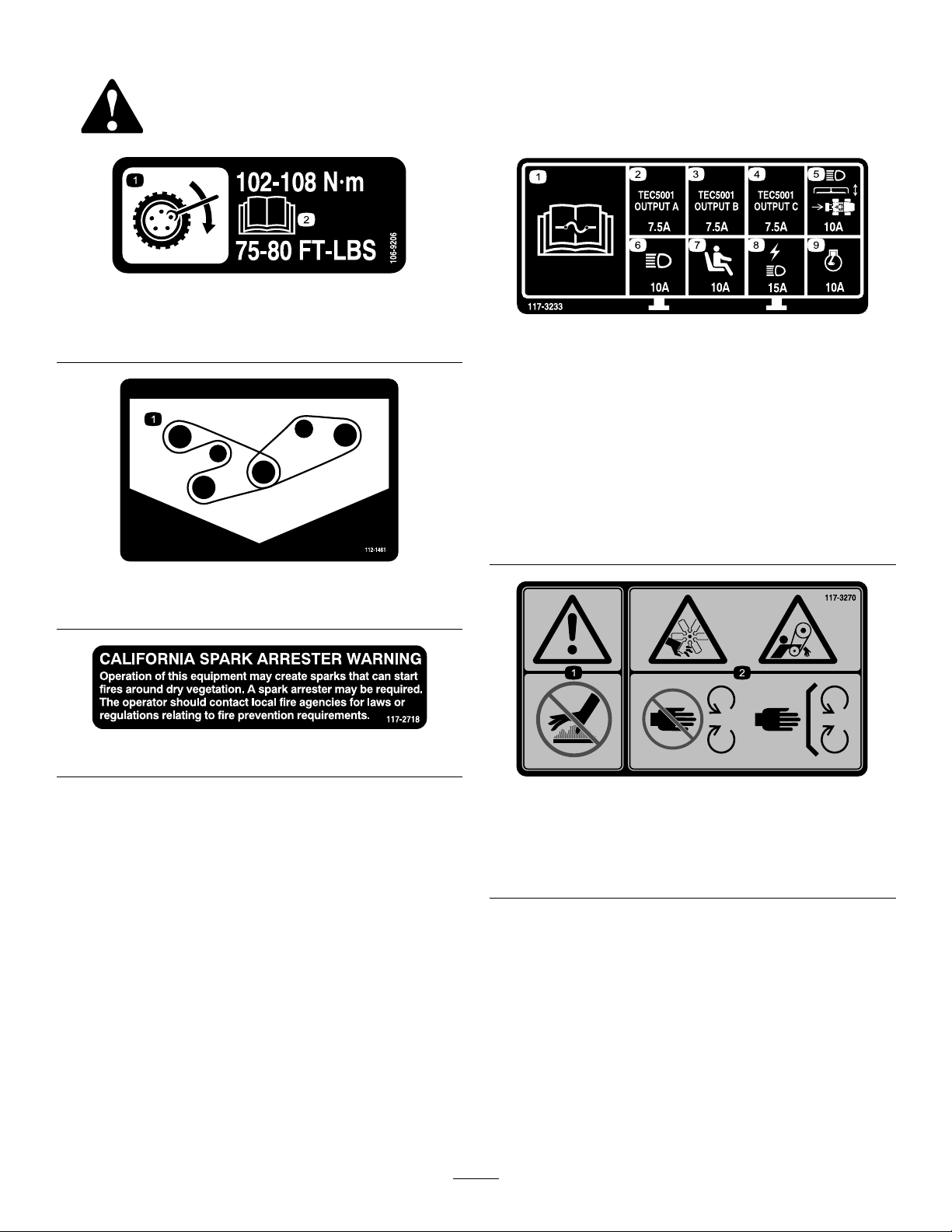
106-9206
1.Wheel-torquespecications
2.ReadtheOperator'sManual.
112-1461
1.Beltrouting
117-2718
117-3233
1.ReadtheOperator'sManualforinformationonfuses.
2.4-wheelsteersolenoid—7.5A
3.PTOenable,4-wheel-steerlamp,decklift,deckoat—7.5A
4.Glowindicator,fuel-runsolenoid,diagnosticlight,start—7.5
A
5.Headlights,deckactuator,powertakeoff—10A
6.Lights—15A
7.Operator-presenceswitch—10A
8.Powerpoint,lights—15A
9.Engine—10A
1.Warning—donottouchthehotsurface.
2.Cutting/dismembermenthazard,hand;entanglement
hazard,belt—stayawayfrommovingparts,keepallguards
andshieldsinplace.
5
117-3270
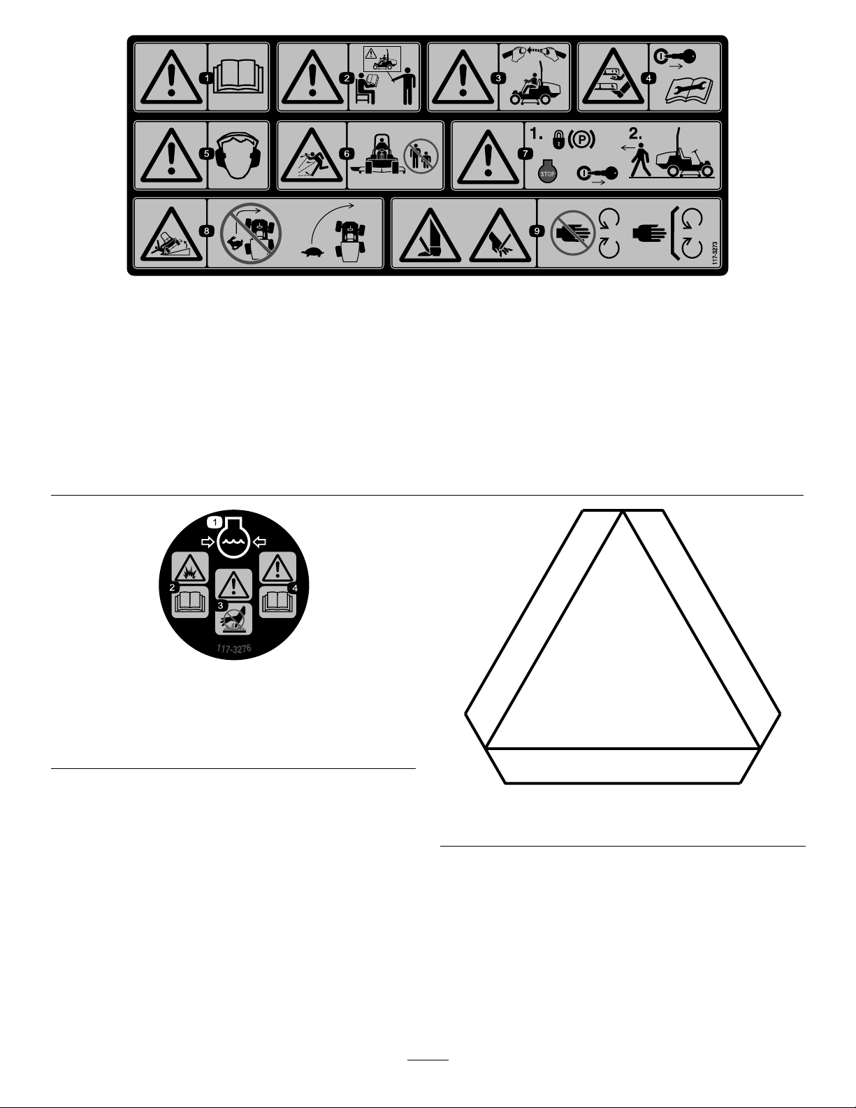
117-3273
1.Warning—readtheOperator'sManual.6.Thrownobjecthazard—keepbystandersasafedistancefrom
2.Warning—donotoperatethismachineunlessyouaretrained.7.Warning—locktheparkingbrake,stoptheengine,and
3.Warning—weartheseatbeltwhenseatedintheoperator's
position.
4.Cutting/dismembermenthazardofhandorfoot—removethe
ignitionkeyandreadtheinstructionsbeforeservicingor
performingmaintenance.
5.Warning—wearhearingprotection.
themachine.
removetheignitionkeybeforeleavingthemachine.
8.Tippinghazard—lowerthecuttingunitwhendrivingdown
slopes;slowthemachinebeforeturning,donotturnathigh
speeds.
9.Cuttinghazardofhandorfoot—stayawayfrommovingparts;
keepallguardsinplace.
117-3276
1.Enginecoolantunder
pressure
2.Explosionhazard—read
theOperator'sManual.
3.Warning—donottouchthe
hotsurface.
4.Warning—readthe
Operator'sManual.
6
120-0250
1.Slow-movingvehicle
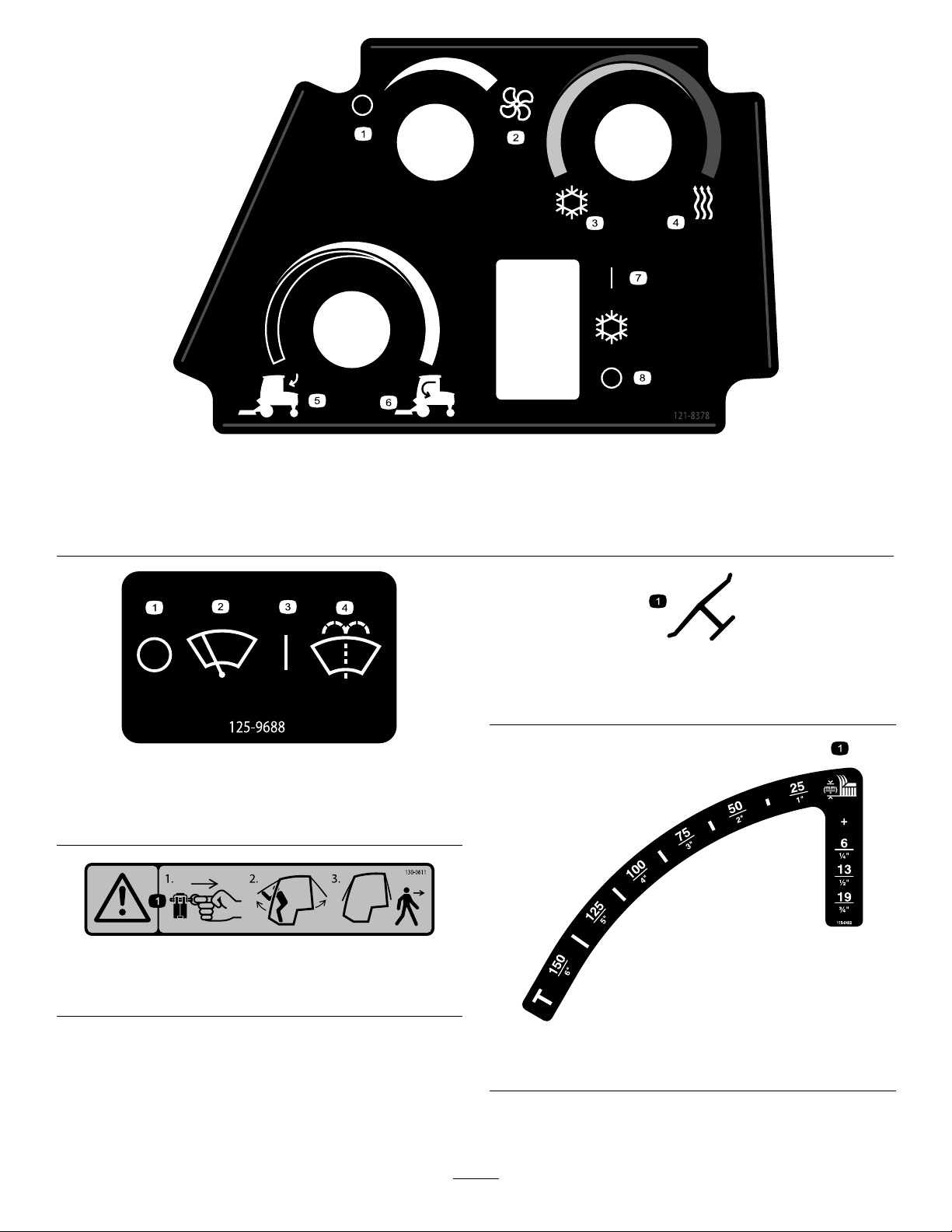
121-8378
1.Fan—off
2.Fan—onfull
3.Coldair7.Airconditioner—off
4.Hotair8.Airconditioner—on
5.Externalair
6.Internalair
1.Indicatesthatthebladeisidentiedasapartfromthe
originalmachinemanufacturer.
125-9688
1.Windshieldwipers—off
2.Windshieldwipers
3.Windshieldwipers—on
4.Spraywindshieldwasher
uid
Manufacturer'sMark
130-0611
1.Warning—1)Removethepin;2)Raisethedoors;3)Exit
thecab
115-0492
1.Heightofcut(mm)
7
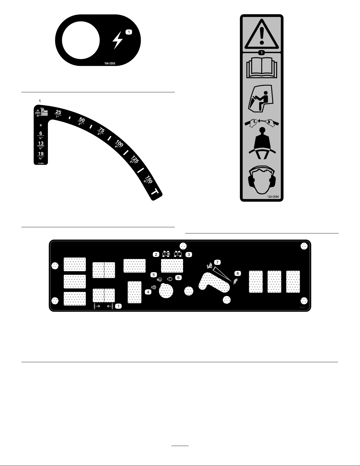
1.Electricalpowerpoint
00
0
0
0
0
00
00
000
106-2353
115-0493
1.Heightofcut(mm)
125–7427
1.Raise/Lowerdecks
2.2-wheelsteering6.Engine—start
3.4-wheelsteering7.Fast
4.Engine—stop
130-0594
1.Warning—readtheOperator’sManual;whensittinginthe
cab,alwayswearaseatbelt;wearhearingprotection.
5.Engine—run
8.Slow
8

BatterySymbols
Someorallofthesesymbolsareonyourbattery .
1.Explosionhazard
2.Nore,opename,or
smoking
3.Causticliquid/chemical
burnhazard
4.Weareyeprotection.9.Flusheyesimmediately
5.ReadtheOperator's
Manual.
6.Keepbystandersasafe
7.Weareyeprotection;
8.Batteryacidcancause
10.Containslead;donot
distancefromthebattery.
explosivegasescan
causeblindnessandother
injuries.
blindnessorsevereburns.
withwaterandgetmedical
helpfast.
discard
9

Setup
LooseParts
Usethechartbelowtoverifythatallpartshavebeenshipped.
ProcedureDescription
PTOdriveshaft
Bolt(5/16x1-3/4inches)
1
2
3
4
Locknut(5/16inch)
Rollpin(3/16x1-1/2inches)
Retainerpin2
Greasetting
Washerheadscrew(5/16x7/8inch)
Nopartsrequired
Nopartsrequired
MediaandAdditionalParts
Description
Operator'sManual
Engineoperator'smanual1
PartsCatalog
Operatortrainingmaterial
Qty.
Qty.
1
4
4
2
2
2
–
–
1
1
1
Readbeforeoperatingthemachine
Readbeforeoperatingthemachine
Usereferencepartnumbers
Viewthevideobeforeoperatingthemachine.
InstallthePTOdriveshafttoaoptional
deckorQAS.
Usethehardwaretoinstalltheoptional
mowerdeck.
Checkthetirepressure.
Checkthehydraulicuid,engineoil,
andcoolantlevels.
Use
Use
1
InstallingthePTODriveshaft toanOptionalMowerDeckor QAS
Partsneededforthisprocedure:
1
PTOdriveshaft
4
Bolt(5/16x1-3/4inches)
4
Locknut(5/16inch)
2
Rollpin(3/16x1-1/2inches)
Procedure
Note:InstallingthePTOdriveshaftiseasierifyouposition
themachineonahoist.
1.Parkmachineonalevelsurface,shutofftheengine,
engagetheparkingbrake,andremovekeyfromthe
ignitionswitch.
WARNING
Donotstarttheengineandengagethe
PTOswitchwhenthePTOdriveshaftis
disconnectedfromthecuttingdeck.Ifyou
starttheengineandthePTOshaftisallowed
torotate,seriouspersonalinjuryandmachine
damagecouldresult.BeforethePTO
driveshaftisdisconnectedfromthecutting
deck,disconnectthePTOsolenoid-valve-coil
connectorfromthewireharnesstoprevent
unintentionallyengagingthePTOclutch.
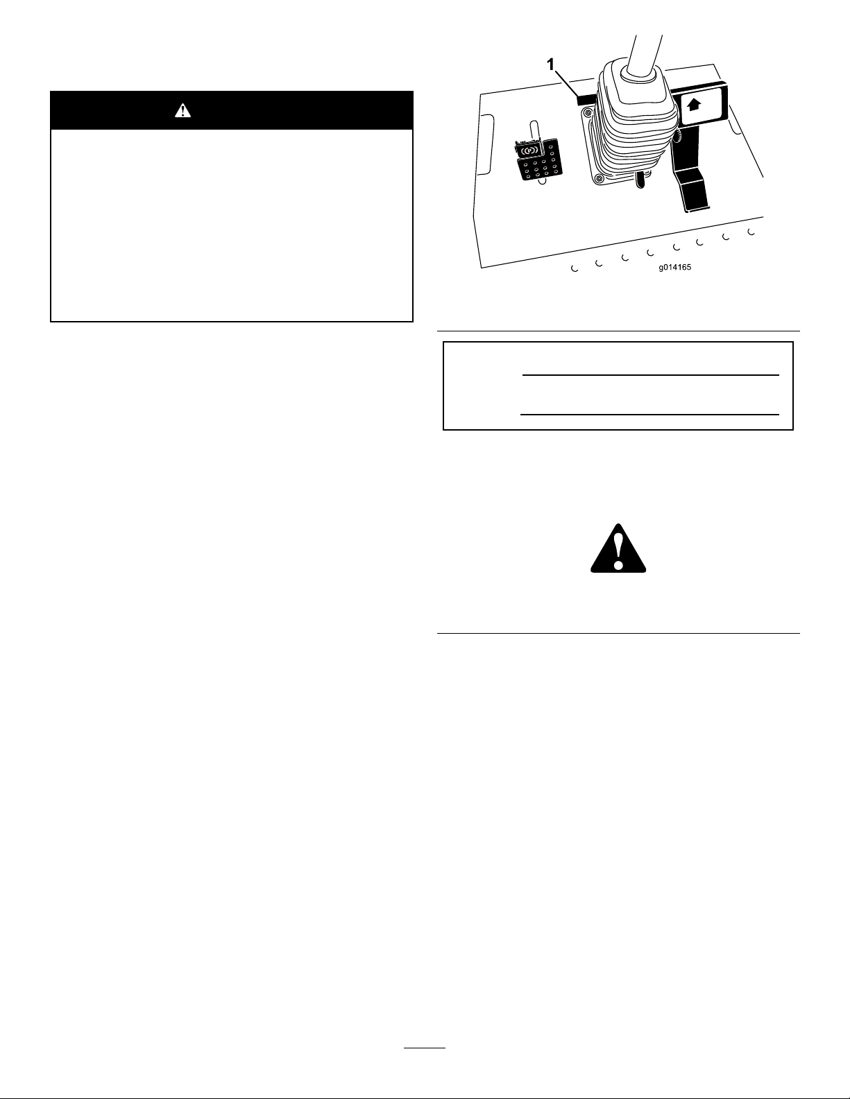
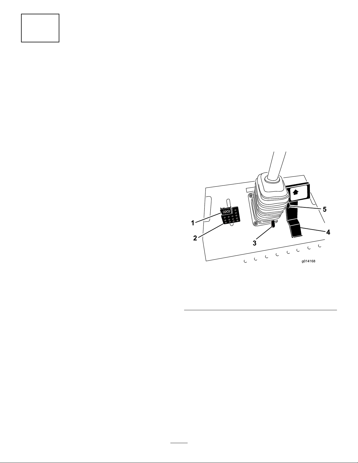
2.Disconnectthewire-harnessconnectorfromthePTO
solenoid-valve-coilconnector(Figure3).
10

G018339
1
G018340
1
2
3
4
5
8.Afteryouconnecttheotherendofthedriveshaftto
theattachmentgearboxshaft,connectthewire-harness
connectortothePTOsolenoid-valve-coilconnector
(Figure3).
2
UsingtheOptional
Mower-Deck-Mounting
Figure3
1.Wire-harnessconnector
3.PositionthePTOdriveshaftunderthefrontofthe
machine.Ensurethattheslip-shaftyokeofthe
driveshaftispositionedtowardthetransmission
driveshaft(Figure4).
Figure4
1.Transmissiondriveshaft
2.Bolt5.Rollpin
3.PTOdriveshaft
4.Locknut
Hardware
Partsneededforthisprocedure:
2Retainerpin
2
Greasetting
2
Washerheadscrew(5/16x7/8inch)
Procedure
Note:Thesecomponentsandprocedurearerequiredonly
ifamowerdeckthatrequiresretainerpinsismountedtothe
tractionunit.RefertothemowerdeckOperator’ sManualfor
theinstallationinstructions.
Note:Ifyouarenotinstallingamowerdeckonthetraction
unit,removeortieupthe4deck-liftchainsfromthelift
suspension.
3
CheckingtheTirePressure
4.Alignthesplineandroll-pinholeofthedriveshaftyoke
withthetransmissiondriveshaft.
5.SlidethePTOdriveshaftendyokeontothe
transmissiondriveshaft.
6.SecuretheendyokeofthePTOdriveshaftasfollows:
A.Installtherollpinintheendyokeandshaft.
B.Installtheboltsthroughthedriveshaftendyoke.
C.Installandtightenthelocknutstosecuretheend
yoketothePTOdriveshaft.
Note:Retaintheremainingbolts,locknuts,and
rollpintosecuretheotherendofthedriveshaft
totheattachmentgearboxshaft.
D.Torquethelocknutsto20to25N-m(175to225
in-lb).
7.LubricatethegreasettingsonthePTOdriveshaft.
NoPartsRequired
Procedure
Thetiresareoverinatedforshipping.Therefore,release
someoftheairtoreducethepressure.Alltiresshouldbe
inatedto172kPa(25psi).
11
ProductOverview
4
CheckingtheFluidLevels
NoPartsRequired
Procedure
1.Checkthehydraulic-uidlevelbeforestartingthe
engine,refertoCheckingtheHydraulicSystem(page
45).
2.Checktheengine-oillevelbeforestartingtheengine,
refertoCheckingtheEngine-OilLevel(page35).
3.Checkthecoolingsystembeforestartingtheengine;
refertoCheckingtheCoolingSystem(page41).
Controls
Becomefamiliarwithallthecontrolsbeforeyoustartthe
engineandoperatethemachine.
TractionPedal
Thetractionpedal(Figure5)controlstheforwardandreverse
operation.Pressthetopofthepedaltomoveforwardand
thebottomtomoverearward.Thegroundspeeddependson
howfaryoupressthepedal.Fornoload,maximumground
speed,fullypressthepedalwhilethethrottleisintheFAST
position.
Tostopthemachine,reducethefootpressureonthetraction
pedalandallowittoreturntothecenterposition.
Figure5
1.Parkingbrake4.Tractionpedal
2.Brakepedal
3.Tilt-steeringpedal
5.Thisfeaturenolonger
existsonthemachine.
BrakePedal
Usethebrakepedalwiththebrake-pedallatchtoengageand
disengagetheparkingbrake(Figure5).Tostopthemachine,
releasethetractionpedalandallowittoreturntothecenter
position.Youcanusethebraketoassistinstoppingthe
machineinanemergencysituation.
ParkingBrake
Toengagetheparkingbrake,pushdownonthebrakepedal
andpressthetopforwardtolatch(Figure5).T oreleasethe
parkingbrake,pressthebrakepedaluntiltheparkingbrake
latchretractswithoutcontactingthelockingmechanism.
12
TiltSteeringPedal
Totiltthesteeringwheeltowardyou,pressthefootpedal
down,pullthesteeringtowertowardyoutothemost
comfortableposition,andreleasethepedal(Figure5).To
movethesteeringwheelawayfromyou,pressthefootpedal
andreleaseitwhenthesteeringwheelreachesthedesired
operatingposition.
themachinewiththethrottleintheFASTpositionwhen
operatingattachments.
Power-Takeoff(PTO)Switch
Thepower-takeoff(PTO)switchstartsandstopsthe
attachment(Figure6).
IgnitionSwitch
Theignitionswitchhas3positions:OFF,ON/PREHEAT,and
START(Figure6).
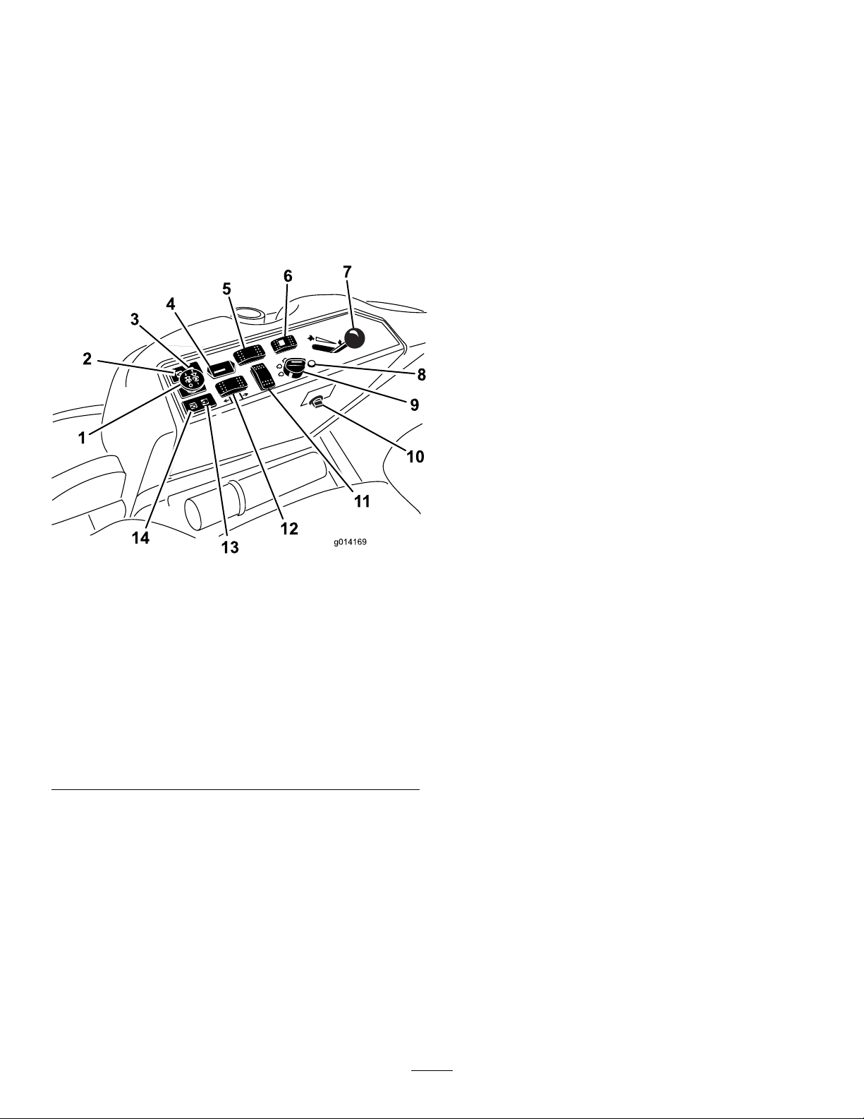
Figure6
1.Power-takeoff(PTO)
switch
2.Oil-pressure-warninglight
3.Charge-indicatorlight
4.Hourmeter
5.Differential-lockswitch
(2-wheel-driveonly)
6.Steering-selectorswitch
(4-wheel-driveonly)
7.Throttlelever
8.Diagnosticlight
(4-wheel-driveonly)
9.Ignitionswitch
10.Powerpoint
11.Optionalswitchlocation
12.Deck-liftswitch
13.Glow-pluglight
14.Coolant-temperature-warning
light
SteeringSelectorSwitch
Pressthesteeringselectorswitchtothereartoengage4-wheel
steeringandforwardtoreturnto2-wheelsteering(Figure6).
HourMeter
Thehourmeter(Figure6)recordsthenumberofhoursthat
theenginehasoperated.Itoperateswhenthekeyswitchis
intheRUNposition.Usethesetimesforschedulingregular
maintenance.
Glow-Plug-IndicatorLight(Orange
Light)
Theglow-plug-indicatorlight(Figure6)turnsonwhenyou
turntheignitionswitchtotheONposition.Itremainsonfor
6seconds.Whenthelightturnsoff,youcanstarttheengine.
Engine-Coolant-Temperature-Warning
Light
Thislightglowsandtheattachmentstopsifthetemperature
oftheenginecoolantishigh(Figure6).Ifyoudonotstop
themachineandthecoolanttemperaturerisesanother7°C
(20°F),theengineshutsoff.
Important:Iftheattachmentshutsdownandthe
temperaturewarninglightison,pushthePTOknob
down,drivethemachinetoasafe,atarea,movethe
throttlelevertotheSLOWposition,allowthetraction
pedaltomovetotheNEUTRALposition,andengage
theparkingbrake.Allowtheenginetoidleforseveral
minuteswhileitcoolstoasafelevel.Shutofftheengine
andcheckthecoolingsystem;refertoCheckingthe
CoolingSystem(page41).
DiagnosticLight
Thediagnosticlightilluminateswhenthesystemdetectsa
fault(Figure6).
ThrottleLever
Thethrottlelever(Figure6)controlstheenginespeed.
MovingthethrottleleverforwardtowardtheFASTposition
increasestheenginespeed.Movingitrearwardtowardthe
SLOWpositiondecreasestheenginespeed.Thethrottle
controlsthespeedofthePTOand,withthetractionpedal,
controlsthegroundspeedofthemachine.Alwaysrun
ChargeIndicator
Thechargeindicatorilluminateswhenthecharging-system
circuitmalfunctions(Figure6).
Oil-Pressure-WarningLight
Theoil-pressure-warninglight(Figure6)glowswhentheoil
pressureinenginedropsbelowasafelevel.Iflowoilpressure
everoccurs,shutofftheengineanddeterminethecause.
Repairthedamagebeforestartingtheengineagain.
13
FuelGauge
1
2
3
4
5
6
7
8
g028431
9
Temperature-Control-Knob
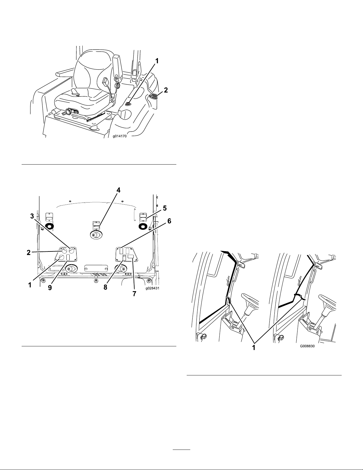
Thefuelgauge(Figure7)indicatestheamountoffuel
remaininginthefueltank.
Figure7
1.Fuelgauge2.Fuel-tankcap
CabControls
Rotatethetemperature-controlknobtoregulatetheair
temperatureinthecab(Figure8).
Windshield-WiperSwitch
Usethisswitchtoturnthewindshieldwipersonoroff
(Figure8).
PowerOutlet
Usethis15A,12VDCpoweroutlettopowercompatible
devices(Figure8).
LightsSwitch
Usethisswitchtoturntheheadlightsandtaillightonoroff
(Figure8).
FlashersSwitch
Usethisswitchtoturntheashers(hazardlights)onoroff
(Figure8).
Air-ConditioningSwitch
Usethisswitchtoturntheairconditioningonoroff(Figure
8).
Figure8
1.Air-recirculationcontrol5.Poweroutlet
2.Fancontrol6.Lightsswitch
3.Temperaturecontrol7.Flashersswitch
4.Windshield-wiperswitch8.Air-conditioningswitch
Air-RecirculationControl
Setsthecabtoeitherrecirculatetheairinthecabinortodraw
airintothecabinfromoutside(Figure8).
•Setittorecirculatetheairwhenusingtheair-conditioning.
•Setittodrawairinwhenusingtheheaterorfan.
Fan-ControlKnob
WindshieldLatch
Liftupthelatchestoopenthewindshield(Figure9).Pressin
thelatchtolockthewindshieldintheopenposition.Pullout
anddownonthelatchtocloseandsecurethewindshield.
Figure9
1.Windshieldlatch
RearWindowLatch
Liftupthelatchestoopentherearwindow .Pressinthelatch
tolockthewindowintheopenposition.Pulloutanddown
onthelatchtocloseandsecurethewindow(Figure9).
Rotatethefan-controlknobtoregulatethespeedofthefan
(Figure8).
Important:Y oumustclosetherearwindowbefore
openingthehood;otherwise,damagemayoccur.
14

Specications
Note:Specicationsanddesignaresubjecttochange
withoutnotice.
Length
Width(RearWheels)147.3cm(58inches)
Height
Weight
MachinewithoutaDeck
Machinewith72-inchBase
Deck
Machinewith72-inch
Side-DischargeDeck
Attachments/Accessories
AselectionofToroapprovedattachmentsandaccessoriesis
availableforusewiththemachinetoenhanceandexpand
itscapabilities.ContactyourAuthorizedServiceDealeror
Distributororgotowww .Toro.comforalistofallapproved
attachmentsandaccessories.
241.3cm(95inches)
221cm(87inches)
1,361kg(3,000lb)
1,531kg(3,375lb)
1,571kg(3,464lb)
Operation
Note:Determinetheleftandrightsidesofthemachine
fromthenormaloperatingposition.
BeforeOperation
BeforeOperationSafety
GeneralSafety
•Neverallowchildrenoruntrainedpeopletooperateor
servicethemachine.Localregulationsmayrestrictthe
ageoftheoperator.Theownerisresponsiblefortraining
alloperatorsandmechanics.
•Becomefamiliarwiththesafeoperationoftheequipment,
operatorcontrols,andsafetysigns.Knowhowtostop
themachineandenginequickly.
•Checkthatallsafetydevicesareattachedand
functioningproperly.Thisincludes,butisnotlimitedto,
operator-presencecontrols;safetyswitchesandshields;
therolloverprotectionsystem(ROPS);attachments;and
brakes.Donotoperatethemachineunlessallsafety
devicesareinpositionandfunctioningasintendedby
themanufacturer.
•Alwaysinspectthemachinetoensurethattheblades,
bladebolts,andcuttingassemblyarenotwornor
damaged.Replacewornordamagedbladesandboltsin
setstopreservebalance.
•Inspecttheareawhereyouwillusethemachineand
removeallobjectsthatthemachinecouldpotentially
throw .
•Evaluatetheterraintodeterminetheappropriate
equipmentandanyattachmentsoraccessoriesrequiredto
operatethemachineproperlyandsafely.
15

FuelSafety
FillingtheFuelTank
DANGER
Incertainconditions,fuelisextremelyammable
andhighlyexplosive.Areorexplosionfromfuel
canburnyouandothersandcandamageproperty.
•Fillthefueltankoutdoors,inanopenarea,when
theengineiscold.Wipeupanyfuelthatspills.
•Neverllthefueltankinsideanenclosedtrailer.
•Neversmokewhenhandlingfuel,andstayaway
fromanopenameorwherefuelfumesmaybe
ignitedbyaspark.
•Storefuelinanapprovedcontainerandkeepit
outofthereachofchildren.Neverbuymore
thana180-daysupplyoffuel.
•Donotoperatethemachinewithouttheentire
exhaustsysteminplaceandinproperworking
condition.
WARNING
Fuelisharmfulorfatalifswallowed.Long-term
exposuretovaporscancauseseriousinjuryand
illness.
•Avoidprolongedbreathingofvapors.
•Keepyourhandsandfaceawayfromthenozzle
andthefuel-tankopening.
•Keepfuelawayfromyoureyesandskin.
•Useonlyanapprovedfuelcontainer.
•Neverremovethefuelcaporaddfueltothefueltank
whiletheengineisrunning.
•Neverllcontainersinsideavehicleoronatruckor
trailerbedwithaplasticliner.Alwaysplacecontainerson
thegroundandawayfromyourvehiclebeforelling.
•Removetheequipmentfromthetruckortrailerandadd
fueltoitwhileitisontheground.Ifthisisnotpossible,
thenaddfuelusingaportablecontainerratherthanfrom
afuel-dispensernozzle.
RecommendedFuel
Useonlyclean,freshdieselfuelorbiodieselfuelswithlow
(<500ppm)orultralow(<15ppm)sulfurcontent.The
minimumcetaneratingshouldbe40.Purchasefuelin
quantitiesthatyoucanusewithin180daystoensurethat
thefuelisfresh.
FuelT ankCapacity:51L(13.5USgallons)
Usesummer-gradedieselfuel(No.2-D)attemperatures
above-7°C(20°F)andwintergrade(No.1-DorNo.
1-D/2-Dblend)belowthattemperature.Usingwinter-grade
fuelatlowertemperaturesprovidealowerashpointand
cold-owcharacteristics,whicheasesstartingandreduces
pluggingofthefuellter.
Usingsummer-gradefuelabove-7°C(20°F)contributes
towardlongerlifeofthefuelpumpandincreasedpower
comparedtowinter-gradefuel.
Important:Donotusekeroseneorgasolineinsteadof
dieselfuel.Failingtoobservethiscautionwilldamage
theengine.
BiodieselReady
Thismachinecanalsouseabiodieselblendedfuelofup
toB20(20%biodiesel,80%petrodiesel).Thepetrodiesel
portionshouldbeultra-lowsulfur.Observethefollowing
precautions:
•Thebiodieselportionofthefuelmustmeetspecication
ASTMD6751orEN14214.
•TheblendedfuelcompositionshouldmeetASTMD975
orEN590.
•Biodieselblendsmaydamagepaintedsurfaces.
•UseB5(biodieselcontentof5%)orlesserblendsincold
weather.
•Checkallseals,hoses,andgasketsincontactwithfuelas
theymaydegradeovertime.
•Espectthefuelltertoplugupforatimeafterconverting
tobiodiesel-blendedfuel.
•Contactyourdistributorformoreinformationon
biodieselfuel.
•Keepthefuel-dispensernozzleincontactwiththerimof
thefueltankorcontaineropeningatalltimesuntilfueling
iscomplete.Donotuseanozzlelock-opendevice.
•Ifyouspillfuelonyourclothing,changeyourclothing
immediately.
•Fillthefueltankuntilthefuellevelis25mm(1inch)
belowthebottomofthellerneck.Donotoverllthe
fueltank.Replacethefuel-tankcapandtightenitsecurely .
Note:Ifpossible,llthefueltankaftereachuse.This
minimizespossiblebuildupofcondensationinsidethefuel
tank.
1.Parkthemachineonalevelsurface.
2.Shutofftheengineandsettheparkingbrake.
3.Cleanaroundthefuel-tankcapandremovethecap
(Figure10).
16
 Loading...