

Page 1

FormNo.3383-175RevA
Groundsmaster
®
360
Multi-PurposeMachine
ModelNo.31222—SerialNo.314000001andUp
ModelNo.31223—SerialNo.314000001andUp
Registeratwww.T oro.com.
OriginalInstructions(EN)
*3383-175*A
Page 2
ThisproductcomplieswithallrelevantEuropeandirectives,
fordetailspleaseseetheseparateproductspecicDeclaration
ofConformity(DOC)sheet.
WARNING
CALIFORNIA
Proposition65Warning
Thisproductcontainsachemicalorchemicals
knowntotheStateofCaliforniatocausecancer,
birthdefects,orreproductiveharm.
Dieselengineexhaustandsomeofits
constituentsareknowntotheStateof
Californiatocausecancer,birthdefects,
andotherreproductiveharm.
Becauseinsomeareastherearelocal,state,orfederal
regulationsrequiringthatasparkarresterbeusedonthe
engineofthismachine,asparkarresterisavailableas
anoption.Ifyourequireasparkarrester,contactyour
AuthorizedToroServiceDealer.
GenuineT orosparkarrestersareapprovedbytheUSDA
ForestryService.
Important:ItisaviolationofCaliforniaPublic
ResourceCodeSection4442touseoroperatetheengine
onanyforest-covered,brush-covered,orgrass-covered
landwithoutasparkarrestermufermaintainedin
workingorder,ortheengineconstricted,equipped,and
maintainedforthepreventionofre.Otherstatesor
federalareasmayhavesimilarlaws.
CustomerServiceandhavethemodelandserialnumbersof
yourproductready.
Figure1identiesthelocationofthe
modelandserialnumbersontheproduct.Writethenumbers
inthespaceprovided.
Figure1
1.Modelandserialnumberlocation
ModelNo.
SerialNo.
Thismanualidentiespotentialhazardsandhassafety
messagesidentiedbythesafetyalertsymbol(Figure2),
whichsignalsahazardthatmaycauseseriousinjuryordeath
ifyoudonotfollowtherecommendedprecautions.
Introduction
Thismachineisaride-on,multi-purposemachineintended
tobeusedbyprofessional,hiredoperatorsincommercial
applications.Itisprimarilydesignedformaintaininggrass
onwell-maintainedlawnsinparks,sportselds,andon
commercialgrounds.Itisnotdesignedforcuttingbrush,
mowinggrassandothergrowthalongsidehighways,orfor
agriculturaluses.
Readthisinformationcarefullytolearnhowtooperateand
maintainyourproductproperlyandtoavoidinjuryand
productdamage.Youareresponsibleforoperatingthe
productproperlyandsafely.
YoumaycontactTorodirectlyatwww .Toro.comforproduct
andaccessoryinformation,helpndingadealer,ortoregister
yourproduct.
Wheneveryouneedservice,genuineT oroparts,oradditional
information,contactanAuthorizedServiceDealerorToro
©2013—TheToro®Company
8111LyndaleAvenueSouth
Bloomington,MN55420
Figure2
1.Safetyalertsymbol
Thismanualalsouses2wordstohighlightinformation.
Importantcallsattentiontospecialmechanicalinformation
andNoteemphasizesgeneralinformationworthyofspecial
attention.
Contactusatwww.Toro.com.
2
PrintedintheUSA.
AllRightsReserved
Page 3

Contents
Introduction..................................................................2
Safety...........................................................................4
SafeOperatingPractices...........................................4
ToroRidingMowerSafety........................................5
SoundPowerLevel..................................................6
SoundPressureLevel...............................................6
SoundPressureLevel...............................................6
VibrationLevel......................................................6
SafetyandInstructionalDecals.................................7
Setup...........................................................................14
1InstallingtheDriveShafttoanOptionalMower
DeckorQAS.....................................................14
2OptionalMowerDeckMountingHardware.............15
3AdjustingtheROPS.............................................15
4CheckingtheTirePressure....................................16
5CheckingtheFluidLevels.....................................16
ProductOverview.........................................................16
Controls...............................................................16
Specications........................................................19
Attachments/Accessories........................................19
Operation....................................................................19
AddingFuel...........................................................19
FillingtheFuelTank...............................................20
UsingtheRolloverProtectionSystem(ROPS)
........................................................................20
ThinkSafetyFirst...................................................21
StartingandStoppingtheEngine..............................21
DrivingtheMachine...............................................22
SteeringSelection(4wheeldrivemodels
only).................................................................23
StoppingtheMachine.............................................23
OperatingaMowerDeckor
Attachment(Optional).........................................23
AdjustingtheHeight-of-Cut....................................24
TheSafetyInterlockSystem.....................................25
UnderstandingtheDiagnosticLight.........................25
DiagnosticAceDisplay...........................................26
CheckingtheInterlockSwitches..............................26
PositioningtheStandardSeat...................................28
PositioningtheDeluxeSeat......................................28
Raising/LoweringtheSeat.......................................29
PushingtheMachinebyHand..................................30
LoadingMachines..................................................30
TransportingMachines............................................31
Maintenance.................................................................33
RecommendedMaintenanceSchedule(s)......................33
DailyMaintenanceChecklist....................................34
PremaintenanceProcedures........................................35
UsingtheHoodPropRod.......................................35
Lubrication...............................................................35
GreasingtheBearingsandBushings..........................35
EngineMaintenance..................................................38
ServicingtheAirCleaner.........................................38
CheckingtheEngineOilLevel.................................38
ChangingtheEngineOilandFilter...........................39
AdjustingtheThrottle.............................................39
FuelSystemMaintenance...........................................40
ServicingtheWaterSeparator..................................40
BleedingtheFuelSystem.........................................40
BleedingAirfromtheFuelInjectors..........................40
CleaningtheFuelTank............................................41
FuelLinesandConnections.....................................41
ElectricalSystemMaintenance....................................42
CheckingtheFuses.................................................42
ServicingtheBattery...............................................42
StoringtheBattery..................................................43
DriveSystemMaintenance.........................................43
CheckingtheTirePressure......................................43
CorrectingSteeringMisalignment.............................43
CoolingSystemMaintenance......................................44
CheckingtheCoolingSystem..................................44
CleaningtheRadiator..............................................44
BrakeMaintenance....................................................45
AdjustingtheServiceBrakes....................................45
AdjustingtheParkingBrake....................................46
BeltMaintenance......................................................46
CheckingtheAlternatorBelt...................................46
ControlsSystemMaintenance.....................................47
AdjustingtheTractionDriveforNeutral....................47
AdjustingtheMaximumGroundSpeed.....................47
AdjustingtheSpeedLimiterLever............................48
HydraulicSystemMaintenance....................................49
CheckingtheHydraulicSystem................................49
ChangingtheHydraulicOilAndFilter.......................49
CabMaintenance.......................................................50
MaximizingAirConditionerPerformance..................50
CleaningtheCabAirFilters.....................................50
CleaningtheAirConditioningCoil...........................51
CleaningtheA/CCondenserScreen.........................52
Cleaning...................................................................52
CleaningtheCab....................................................52
WasteDisposal.......................................................52
Storage........................................................................53
Engine..................................................................53
Machine................................................................53
3
Page 4

Safety
ThismachinemeetsorexceedsCENstandardEN836:1997
andANSIB71.4-2012specicationsineffectatthetimeof
production,whentheoptionalmowerdeckisinstalled.
Improperuseormaintenancebytheoperatororownercan
resultininjury.Toreducethepotentialforinjury,comply
withthesesafetyinstructionsandalwayspayattentiontothe
safetyalertsymbol,whichmeansCaution,Warning,or
Danger—personalsafetyinstruction.Failuretocomplywith
theinstructionmayresultinpersonalinjuryordeath.
SafeOperatingPractices
ThefollowinginstructionsareadaptedfromtheCEN
standardEN836:1997andANSIB71.4-2012.
Thisproductiscapableofamputatinghandsandfeetand
throwingobjects.Alwaysfollowallsafetyinstructionsto
avoidseriousinjuryordeath.
Training
•ReadtheOperator'sManualandothertrainingmaterial
carefully.Befamiliarwiththecontrols,safetysigns,and
theproperuseoftheequipment.
•Neverallowchildrenorpeopleunfamiliarwiththese
instructionstousethisequipment.Localregulationscan
restricttheageoftheoperator.
•Neveroperatewhilepeople,especiallychildren,orpets
arenearby .
•Keepinmindthattheoperatororuserisresponsiblefor
accidentsorhazardsoccurringtootherpeopleortheir
property.
•Donotcarrypassengers.
•Alldriversshouldseekandobtainprofessionaland
practicalinstruction.Suchinstructionshouldemphasize:
–theneedforcareandconcentrationwhenworking
withride-onmachines;
–controlofaride-onmachineslidingonaslopewill
notberegainedbytheapplicationofthebrake.The
mainreasonsforlossofcontrolare:
◊insufcientwheelgrip,especiallyonwetgrass;
◊beingdriventoofast;
◊inadequatebraking;
◊thetypeofmachineisunsuitableforitstask;
◊lackofawarenessoftheeffectofground
conditions,especiallyslopes;
◊incorrectloaddistribution.
Preparation
•Whileoperatingthemachine,alwayswearsubstantial
footwearandlongtrousers.Donotoperatethe
equipmentwhenbarefootorwearingopensandals.
•Thoroughlyinspecttheareawheretheequipmentisto
beusedandremoveallobjectswhichmaybethrownby
themachine.
•Replacefaultysilencers/mufers.
•Ifamowerdeckisinstalledonthemachine,beforeusing
it,alwaysvisuallyinspecttoseethattheblades,blade
boltsandcutterassemblyarenotwornordamaged.
Replacewornordamagedbladesandboltsinsetsto
preservebalance.
SafeHandlingofFuels
•Toavoidpersonalinjuryorpropertydamage,use
extremecareinhandlinggasoline.Gasolineisextremely
ammableandthevaporsareexplosive.
•Extinguishallcigarettes,cigars,pipes,andothersources
ofignition.
•Useonlyanapprovedfuelcontainer.
•Neverremovefuelcaporaddfuelwiththeengine
running.
•Allowenginetocoolbeforerefueling.
•Neverrefuelthemachineindoors.
•Neverstorethemachineorfuelcontainerwherethereis
anopename,spark,orpilotlightsuchasonawater
heateroronotherappliances.
•Neverllcontainersinsideavehicleoronatruckor
trailerbedwithaplasticliner.Alwaysplacecontainerson
thegroundawayfromyourvehiclebeforelling.
•Removeequipmentfromthetruckortrailerandrefuelit
ontheground.Ifthisisnotpossible,thenrefuelsuch
equipmentwithaportablecontainer,ratherthanfroma
fueldispensernozzle.
•Keepthenozzleincontactwiththerimofthefueltank
orcontaineropeningatalltimesuntilfuelingiscomplete.
Donotuseanozzlelockopendevice.
•Iffuelisspilledonclothing,changeclothingimmediately.
•Neveroverllfueltank.Replacefuelcapandtighten
securely.
Operation
•Bealert,slowdownandusecautionwhenmakingturns.
Lookbehindandtothesidebeforechangingdirections.
•Donotoperatetheengineinaconnedspacewhere
dangerouscarbonmonoxidefumescancollect.
•Operateonlyindaylightoringoodarticiallight.
•Beforeattemptingtostarttheengine,disengageallblade
attachmentclutchesandshiftintoneutral.
•Rememberthereisnosuchthingasasafeslope.Travel
ongrassslopesrequiresparticularcare.T oguardagainst
overturning:
–donotstoporstartsuddenlywhenonaslope;
–useslowspeedsonslopesandduringtightturns;
4
Page 5

–stayalertforhumpsandhollowsandotherhidden
hazards;
•Watchoutfortrafcwhencrossingornearroadways.
•Whenusinganyattachments,neverdirectdischargeof
materialtowardbystandersnorallowanyonenearthe
machinewhileinoperation.
•Neveroperatethemachinewithdamagedguards,shields,
orwithoutsafetyprotectivedevicesinplace.
•Donotchangetheenginegovernorsettingsoroverspeed
theengine.Operatingtheengineatexcessivespeedmay
increasethehazardofpersonalinjury.
•Beforeleavingtheoperator'sposition:
–disengagethepowertake-offandlowerthe
attachments;
–settheparkingbrake;
–stoptheengineandremovethekey.
•Disengagedrivetoattachments,stoptheengine,and
removetheignitionkey:
–beforechecking,cleaningorworkingonthemachine;
–afterstrikingaforeignobject.Inspectthemachine
fordamageandmakerepairsbeforerestartingand
operatingtheequipment;
–ifthemachinestartstovibrateabnormally(check
immediately).
•Donotoperatethemachineundertheinuenceof
alcoholordrugs.
•Lightningcancausesevereinjuryordeath.Iflightning
isseenorthunderisheardinthearea,donotoperate
themachine;seekshelter.
•Disengagedrivetoattachmentswhentransportingornot
inuse.
•Stoptheengineanddisengagedrivetoattachmentbefore
refueling.
•KeeptheROPSinsafeoperatingconditionby
periodicallythoroughlyinspectingfordamageand
keepingallmountingfastenerstight.
•ReplaceadamagedROPS.Donotrepairorrevise.
•DonotremovetheROPS.
•AnyalterationstoaROPSmustbeapprovedbythe
manufacturer.
MaintenanceandStorage
•Keepallnuts,boltsandscrewstighttobesurethe
equipmentisinsafeworkingcondition.
•Neverstoretheequipmentwithfuelinthetankinsidea
buildingwherefumesmayreachanopenameorspark.
•Allowtheenginetocoolbeforestoringinanyenclosure.
•Toreducetherehazard,keeptheengine,
silencer/mufer,batterycompartmentandfuelstorage
areafreeofgrass,leaves,orexcessivegrease.
•Replacewornordamagedpartsforsafety.
•Ifthefueltankhastobedrained,dothisoutdoors.
•Ifamowerdeckisinstalledonthemachine,takecareas
manuallyrotatingonebladecancauseotherbladesto
rotate.
•Whenmachineistobeparked,storedorleftunattended,
lowertheattachment.
Hauling
•Usecarewhenloadingorunloadingthemachineintoa
trailerortruck.
•Usefullwidthrampsforloadingmachineintotraileror
truck.
•Tiethemachinedownsecurelyusingstraps,chains,cable,
orropes.Bothfrontandrearstrapsshouldbedirected
downandoutwardfromthemachine
RolloverProtectionSystem(ROPS)UseandMaintenance
•TheROPSisanintegralandeffectivesafetydevice.Keep
afoldingROPSintheraisedandlockedpositionanduse
theseatbeltwhenoperatingthemachine.
•LowerafoldingROPStemporarilyonlywhenabsolutely
necessary.Donotweartheseatbeltwhenfoldeddown.
•Beawarethereisnorolloverprotectionwhenafolded
ROPSisinthedownposition.
•Becertainthattheseatbeltcanbereleasedquicklyin
theeventofanemergency.
•Checktheareatobemowedandneverfolddowna
foldingROPSinareaswherethereareslopes,dropoffs
orwater.
•Checkcarefullyforoverheadclearances(i.e.branches,
doorways,electricalwires)beforedrivingunderany
objectsanddonotcontactthem.
ToroRidingMowerSafety
ThefollowinglistcontainssafetyinformationspecictoToro
productsorothersafetyinformationthatyoumustknowthat
isnotincludedintheCENstandard.
•Engineexhaustcontainscarbonmonoxide,whichisan
odorless,deadlypoisonthatcankillyou.Donotrun
engineindoorsorinanenclosedarea.
•Keephands,feet,hairandlooseclothingawayfrom
attachmentdischargearea,undersideofmowerandany
movingpartswhileengineisrunning.
•Donottouchequipmentorattachmentpartswhichmay
behotfromoperation.Allowtocoolbeforeattempting
tomaintain,adjust,orservice.
•Batteryacidispoisonousandcancauseburns.Avoid
contactwithskin,eyesandclothing.Protectyourface,
eyes,andclothingwhenworkingwithabattery.
5
Page 6

•Thismachineisnotdesignedorequippedforon-road
useandisa“slow-movingvehicle.”Ifyoumustcross
ortravelonapublicroad,youshouldbeawareofand
complywithlocalregulations,suchasrequiredlights,
slowmovingvehiclesigns,andreectors.
•Batterygasescanexplode.Keepcigarettes,sparksand
amesawayfrombattery.
•UseonlygenuineTororeplacementpartstoensurethat
originalstandardsaremaintained.
•UseonlyToroapprovedattachments.Warrantymaybe
voidedifusedwithunapprovedattachments.
SoundPowerLevel
Note:Thedatacontainedinthissectiononlypertainsto
unitsmarkedwiththeCElogo.
Thisunithasaguaranteedsoundpowerlevelof101dBA,
whichincludesanUncertaintyValue(K)of1dBA.
Soundpowerlevelwasdeterminedaccordingtothe
proceduresoutlinedinISO11094.
SoundPressureLevel
SlopeOperation
•Donotoperateneardrop-offs,ditches,steepbanksor
water.Wheelsdroppingoveredgescancauserollovers,
whichmayresultinseriousinjury,death,ordrowning.
•Donotoperateonslopeswhengrassiswet.Slippery
conditionsreducetractionandcouldcauseslidingand
lossofcontrol.
•Donotmakesuddenturnsorrapidspeedchanges.
•Reducespeedanduseextremecautiononslopes.
•Removeormarkobstaclessuchasrocks,treelimbs,etc.
fromtheoperatingarea.Tallgrasscanhideobstacles.
•Watchforditches,holes,rocks,dips,andrisesthatchange
theoperatingangle,asroughterraincouldoverturnthe
machine.
•Avoidsuddenstartswhenoperatinguphillbecausethe
machinemaytipbackwards.
•Alwaysavoidsuddenstartingorstoppingonaslope.If
tireslosetraction,disengagetheattachmentandproceed
slowlyofftheslope.
•Followthemanufacturer'srecommendationsforwheel
weightsorcounterweightstoimprovestability.
•Useextremecarewithallattachments.Thesecanchange
thestabilityofthemachineandcauselossofcontrol.
Model31222
Note:Thedatacontainedinthissectiononlypertainsto
unitsmarkedwiththeCElogo.
Theseunitshaveasoundpressurelevelattheoperator’sear
of85dBA,whichincludesanUncertaintyValue(K)of1dBA.
Soundpressurelevelwasdeterminedaccordingtothe
proceduresoutlinedinEN836.
SoundPressureLevel
Model31223
Note:Thedatacontainedinthissectiononlypertainsto
unitsmarkedwiththeCElogo.
Theseunitshaveasoundpressurelevelattheoperator’sear
of80dBA,whichincludesanUncertaintyValue(K)of1dBA.
Soundpressurelevelwasdeterminedaccordingtothe
proceduresoutlinedinEN836.
VibrationLevel
Note:Thedatacontainedinthissectiononlypertainsto
unitsmarkedwiththeCElogo.
UsingtheRolloverProtectionSystem
(ROPS)
•Keeptherollbarintheraisedandlockedpositionand
usetheseatbeltwhenoperatingthemachine.
•Becertainthattheseatbeltcanbereleasedquicklyin
theeventofanemergency.
•Beawarethereisnorolloverprotectionwhentheroll
barisdown.
•ChecktheareaofoperationandneverfoldtheROPSin
areaswherethereareslopes,dropoffsorwater.
•Lowertherollbaronlywhenabsolutelynecessary.Do
notweartheseatbeltwiththerollbarfoldeddown.
•Checkcarefullyforoverheadclearances(i.e.branches,
doorways,electricalwires)beforedrivingunderany
objectsanddonotcontactthem.
Hand-Arm
Measuredvibrationlevelforrighthand=0.39m/s
Measuredvibrationlevelforlefthand=0.34m/s
UncertaintyValue(K)=0.5m/s
Measuredvaluesweredeterminedaccordingtotheprocedures
outlinedinEN836.
WholeBody
Measuredvibrationlevel=0.41m/s
UncertaintyValue(K)=0.5m/s
6
2
2
2
2
2
Page 7
SafetyandInstructionalDecals
Safetydecalsandinstructionsareeasilyvisibletotheoperatorandarelocatednearanyareaofpotential
danger.Replaceanydecalthatisdamagedorlost.
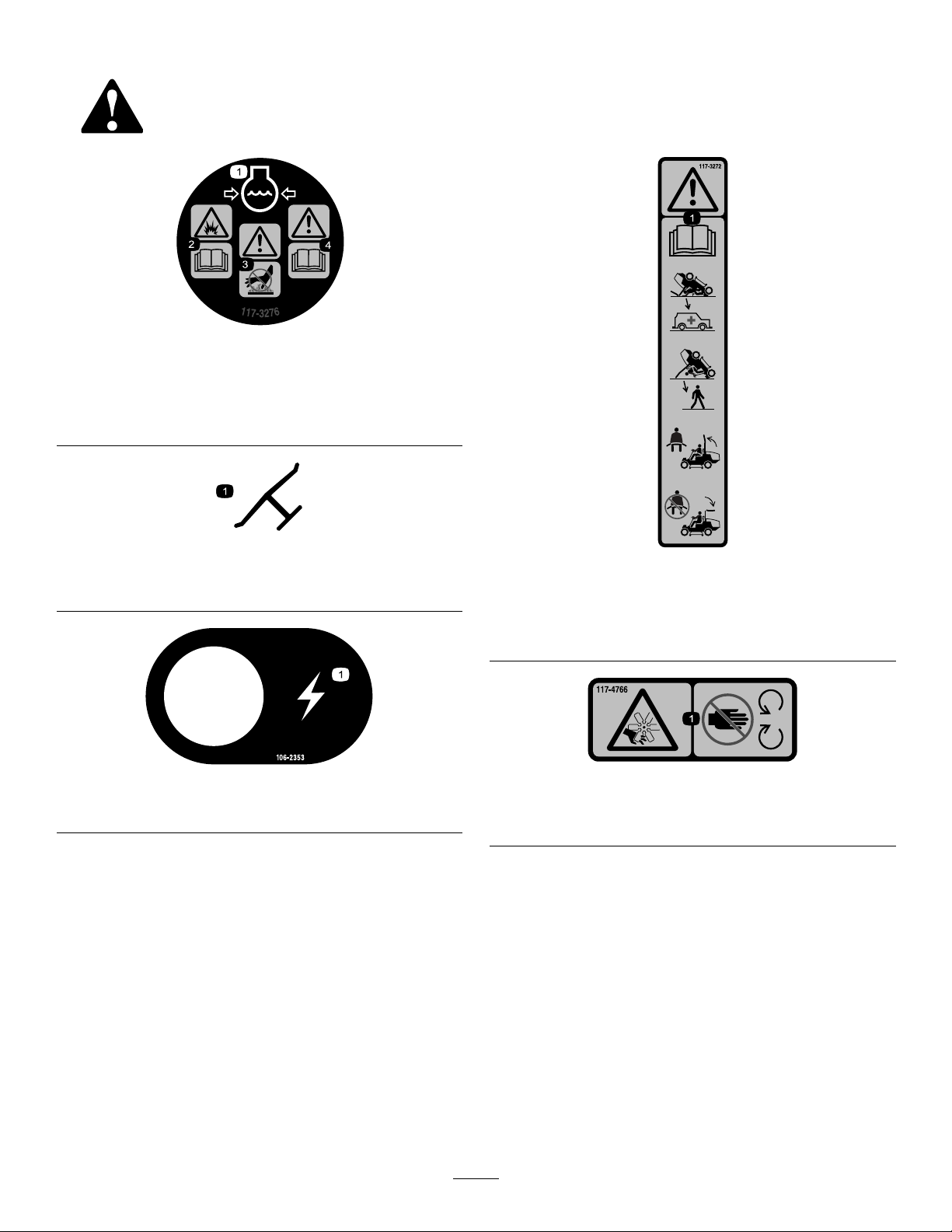
117-3276
1.Enginecoolantunder
pressure
2.Explosionhazard—read
theOperator'sManual.
3.Warning—donottouchthe
hotsurface.
4.Warning—readthe
Operator'sManual.
Manufacturer'sMark
1.Indicatesthebladeisidentiedasapartfromtheoriginal
machinemanufacturer.
106-2353
1.Electricalpowerpoint
117-3272
1.Warning—readtheOperator'sManual;failuretousthe
rolloverprotectionsystem(ROPS)canresultininjuryin
theeventofarollover;wearaseatbeltwhenaROPSisin
place,donotwearaseatbeltwhenROPSislowered.
117-4766
1.Cutting/dismembermenthazard;fan—stayawayfrom
movingparts,keepallguardsandshieldsinplace.
7
Page 8
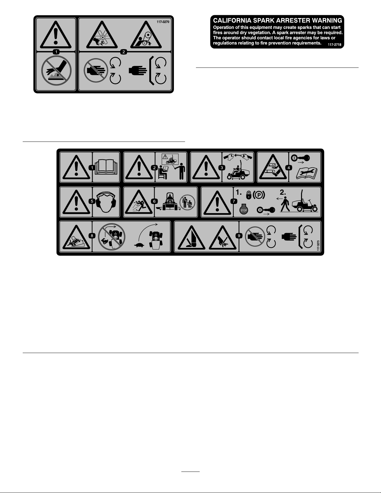
117-3270
1.Warning—donottouchthehotsurface.
2.Cutting/dismembermenthazard,hand;entanglement
hazard,belt—stayawayfrommovingparts,keepallguards
andshieldsinplace.
117–2718
117-3273
1.Warning—readtheOperator'sManual.6.Thrownobjecthazard—keepbystandersasafedistancefrom
2.Warning—donotoperatethismachineunlessyouaretrained.7.Warning—locktheparkingbrake,stoptheengineandremove
3.Warning—weartheseatbeltwhenseatedintheoperator's
position.
4.Cutting/dismembermenthazardofhandorfoot—removethe
ignitionkeyandreadtheinstructionsbeforeservicingor
performingmaintenance.
5.Warning—wearhearingprotection.
themachine.
theignitionkeybeforeleavingthemachine.
8.Tippinghazard—lowerthecuttingunitwhendrivingdown
slopes;slowmachinebeforeturning,donotturnathigh
speeds
9.Cuttinghazardofhandorfoot—stayawayfrommovingparts;
keepallguardsinplace.
8
Page 9
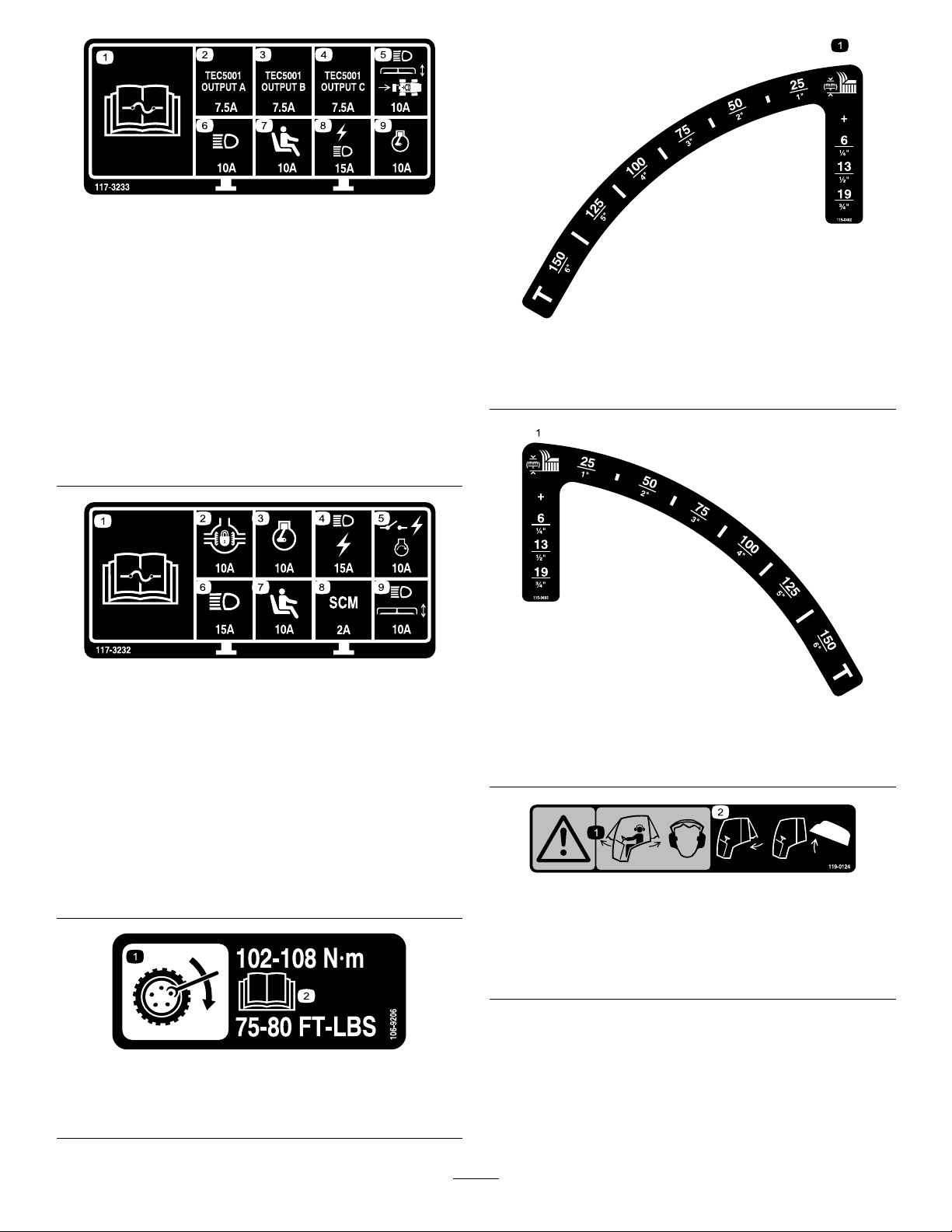
117-3233
4Wheeldrivemodels
1.ReadtheOperator'sManualforinformationonfuses.
2.4wheelsteersolenoid—7.5amp
3.PTOenable,4wheelsteerlamp,decklift,deckoat—7.5
amp
4.Glowindicator,fuelrunsolenoid,diagnosticlight,start—7.5
amp
5.Headlights,deckactuator,powertake–off—10amp
6.Lights—15amp
7.Operatorpresenceswitch—10amp
8.Powerpoint,lights—15amp
9.Engine—10amp
115-0492
Non-cabmodels
1.Heightofcut(mm)
117-3232
2Wheeldrivemodels
1.ReadtheOperator'sManualforinformationonfuses.
2.Differentiallockout—10amp
3.Engine—10amp
4.Lights,powerpoint—15amp
5.Powerswitch,engineignition—10amp
6.Lights—15amp
7.Operatorpresenceswitch—10amp
8.Computer—2amp
9.Headlights,deckactuator—10amp
106-9206
1.Wheeltorquespecications
2.ReadtheOperator'sManual.
115-0493
Cabmodels
1.Heightofcut(mm)
119–0124
(Cabmodels)
1.Warning—whenthecabwindowsareopenwearhearing
protection.
2.Closetherearwindowbeforeattemptingtoopenthehood.
9
Page 10
BatterySymbols
Someorallofthesesymbolsareonyourbattery
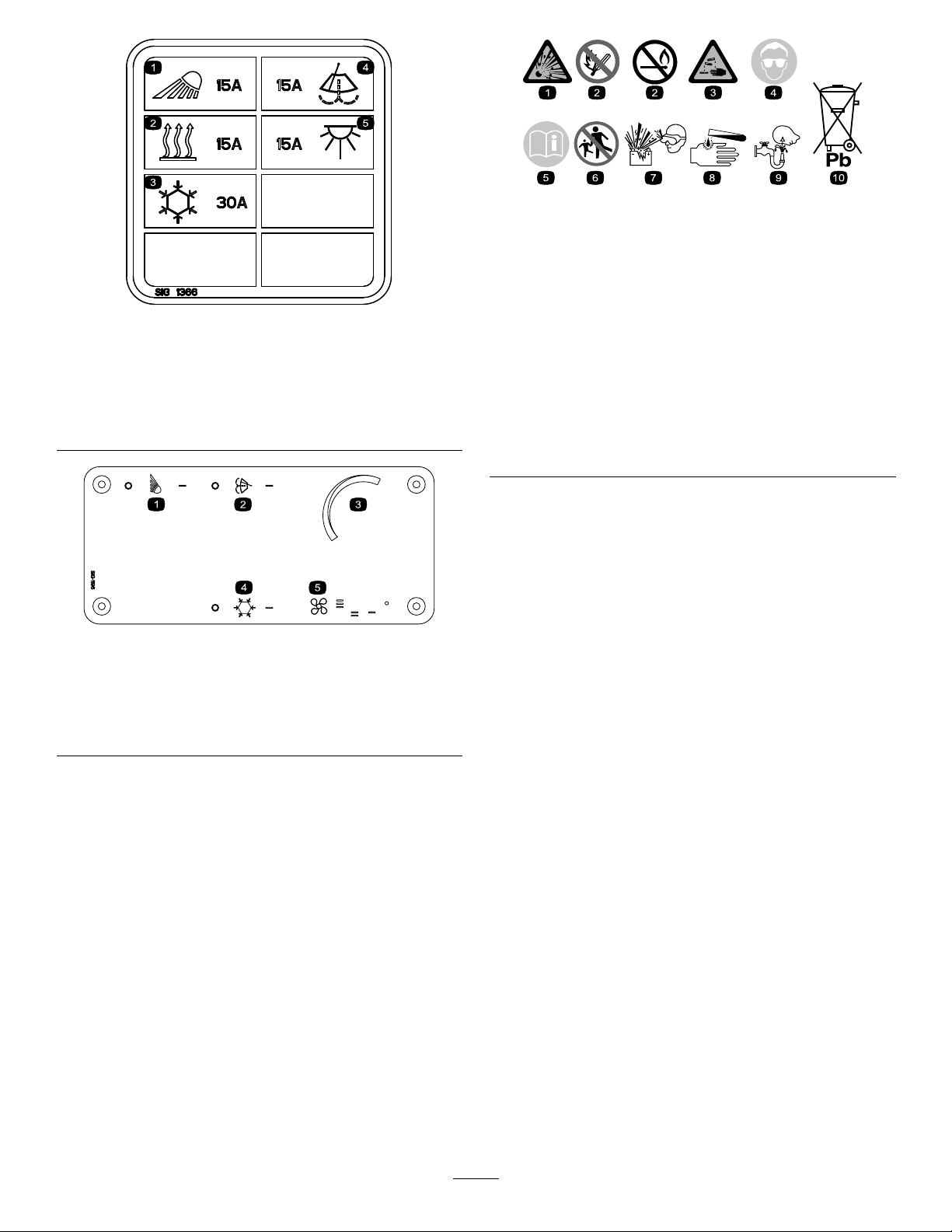
117–2787
(Cabmodels)
1.Headlights,15Afuse
2.Heater,15Afuse5.Domelight,15Afuse
3.Airconditioning,30Afuse
4.Windshieldwipers,15A
fuse
115–5501
(CabModels)
1.Lights4.Airconditioningswitch
2.Windshieldwiperswitch5.Fancontrol
3.Temperaturecontrol
1.Explosionhazard
2.Nore,opename,or
smoking.
3.Causticliquid/chemical
burnhazard
4.Weareyeprotection9.Flusheyesimmediately
5.ReadtheOperator's
Manual.
6.Keepbystandersasafe
7.Weareyeprotection;
8.Batteryacidcancause
10.Containslead;donot
distancefromthebattery.
explosivegasescan
causeblindnessandother
injuries
blindnessorsevereburns.
withwaterandgetmedical
helpfast.
discard.
10
Page 11
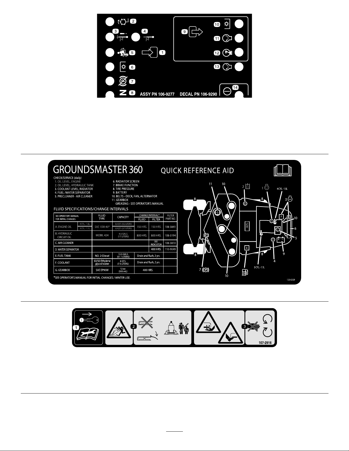
106-9290
Twowheeldrivemodelsonly
1.Inputs5.Inseat
2.Notactive
3.Hightemperatureshutdown
4.Hightemperaturewarning8.Neutral
6.PowerTake-off(PTO)10.PowerTakeOff(PTO)
7.ParkingbrakeOff11.Start
9.Outputs13.Start
14.Power
12.EnergizetoRun(ETR)
1.Removetheignitionkeyandreadthe
Operator'sManualbeforeservicingor
performingmaintenance.
120-0259
107-2916
2.Thrownobjecthazard—donotoperate
themowerwiththedeectorupor
removed,keepthedeectorinplace;
keepbystandersasafedistancefrom
themachine.
11
3.Cutting/dismembermenthazardof
handorfoot,mowerblade—stayaway
frommovingparts.
Page 12
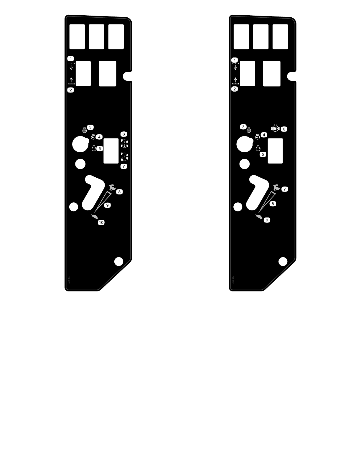
117-3277
Fourwheeldrive,non-cabmodels
120-0257
Twowheelsdrivemodels
1.Lowerdecks6.Two-wheelsteering
2.Raisedecks7.Four-wheelsteering
3.Engine—stop8.Fast
4.Engine—run
5.Engine—start
9.Continuousvariable
setting
10.Slow
1.Lowerdecks
2.Raisedecks7.Fast
3.Engine—stop
4.Engine—run
5.Engine—start
12
6.Differentiallock
8.Continuousvariable
setting
9.Slow
Page 13
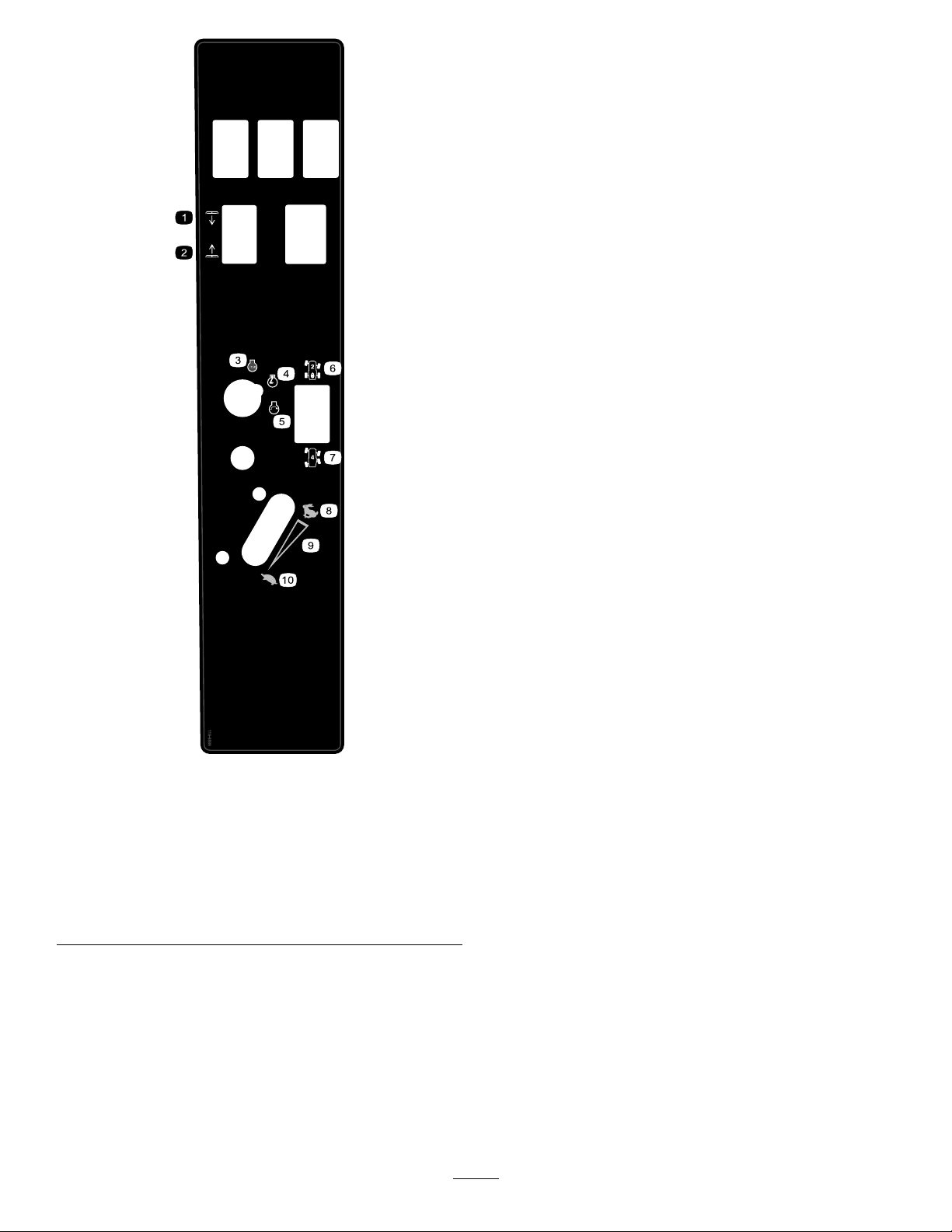
119-9899
Modelswithcabsonly
1.Lowerdecks6.Two-wheelsteering
2.Raisedecks7.Four-wheelsteering
3.Engine—stop8.Fast
4.Engine—run
5.Engine—start
9.Continuousvariable
setting
10.Slow
13
Page 14

Setup
LooseParts
Usethechartbelowtoverifythatallpartshavebeenshipped.
ProcedureDescription
1
2
3
4
5
MediaandAdditionalParts
Description
Operator'sManual
EngineOperator'sManual
Driveshaft
Screw,5/16x1–3/4inch
Locknut,5/16inch
Rollpin,3/16x1–1/2inch
Retainerpin2
Greasetting
Washerheadscrew,5/16x7/8inch
Nopartsrequired
Nopartsrequired
Nopartsrequired
Qty.
1
1
Readbeforeoperatingthemachine
Readbeforeoperatingthemachine
Qty.
Use
1
4
4
2
2
2
–
–
–
Installthedriveshafttoaoptionaldeck
orQAS
Usetoinstalloptionalmowerdeck
AdjusttheROPS
Checkthetirepressure.
Checkthehydraulicuid,engineoil,
andcoolantlevels.
Use
PartsCatalog
OperatorTrainingMaterial
1
InstallingtheDriveShafttoan OptionalMowerDeckorQAS
Partsneededforthisprocedure:
1
Driveshaft
4
Screw,5/16x1–3/4inch
4
Locknut,5/16inch
2
Rollpin,3/16x1–1/2inch
Procedure
Note:PTOdriveshaftinstallationiseasierifthemachineis
positionedonahoist.
1
1
Usereferencepartnumbers
Viewthevideobeforeoperatingthemachine
WARNING
Donotstarttheengineandengagethe
PTOswitchwhenthePTOdriveshaftis
disconnectedfromthecuttingdeck.Ifthe
engineisstartedandthePTOshaftisallowed
torotate,seriouspersonalinjuryandmachine
damagecouldresult.BeforethePTOdrive
shaftisdisconnectedfromthecuttingdeck,
disconnectPTOsolenoidcoilconnector
fromwireharnesstopreventunintentional
engagementofthePTOclutch.
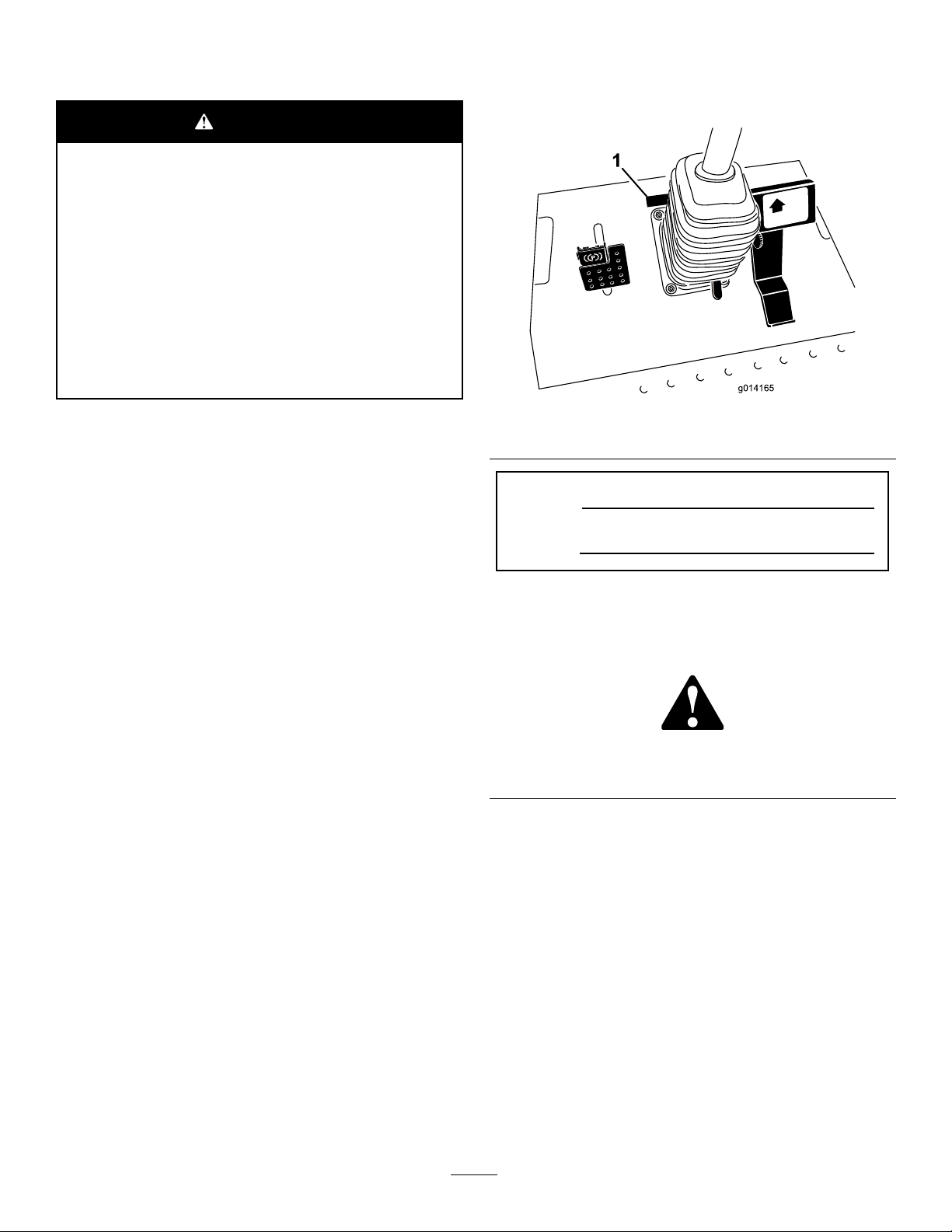
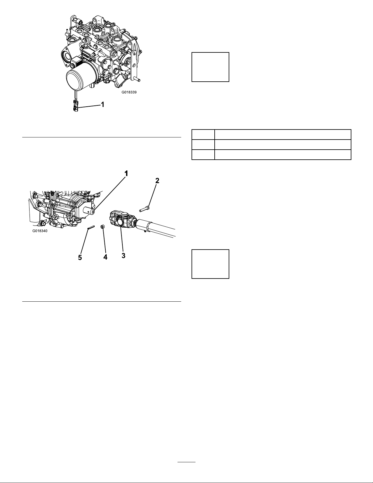
2.TopreventtheunintentionalengagementofthePTO
clutch,disconnectthewireharnesselectricalconnector
fromthePTOsolenoidvalvecoilconnector(Figure3).
1.Parkmachineonalevelsurface,stopengine,engage
parkingbrakeandremovekeyfromtheignitionswitch.
14
Page 15
G018339
1
Figure3
G018340
1
2
3
4
5
1.Wireharnesselectricalconnector
3.PositionthePTOdriveshaftunderthefrontofthe
machine.Makesurethatthedriveshaftslipshaftyoke
(Figure4)istowardthetransmissionPTOshaft.
8.Aftertheotherendofthedriveshaftisconnected
totheattachmentgearboxshaft,connectthewire
harnesselectricalconnectortothePTOsolenoidvalve
coilconnector(
Figure3).
2
OptionalMowerDeck MountingHardware
Partsneededforthisprocedure:
2Retainerpin
2
Greasetting
2
Washerheadscrew,5/16x7/8inch
Procedure
Note:Thesecomponentsandprocedureareonlyrequiredif
amowerdeck,thatrequiresretainerpins,ismountedtothe
tractionunit.RefertotheMowerDeckOperator’sManual
fortheinstallationinstructions
Figure4
1.Transmissiondriveshaft
2.Capscrew
3.PTOshaft
4.Alignthesplineandrollpinholeofdriveshaftyoke
withthetransmissionshaft.
5.SlidePTOdriveshaftendyokeontothetransmission
PTOshaft.
6.SecuretheendyokeofthePTOdriveshaftasfollows:
A.Installtherollpinintheendyokeandshaft.
B.Installthecapscrewsthruthedrivesshaftend
yoke.
C.Installandtightenthelocknutstosecuretheend
yoketothePTOshaft.Torquethelocknutsto20
to25N-m(175to225in-lb).
Note:Retaintheremainingcapscrews,locknuts
androllpintosecuretheotherendofthedrive
shafttotheattachmentgearboxshaft.
4.Locknut
5.Rollpin
Note:Ifamowerdeckisnottobeinstalledonthetraction
unit,removeortieupthe(4)deckliftchainsfromthelift
suspension.
3
AdjustingtheROPS
NoPartsRequired
Procedure
1.Removethehairpincotterpinsandthepinsfromthe
rollbar(Figure5).
2.Raisetherollbartotheuprightpositionandinstall
thetwopinsandsecurethemwiththehairpincotter
pins(Figure5).
Note:Ifyoumustlowertherollbar,pushthebar
forwardtorelievepressureonthepins,removethe
pins,lowerthebarslowly,andsecureitwiththepinsso
thatitdoesnotdamagethehood.
7.LubricatethePTOdriveshaftgreasettings.
15
Page 16
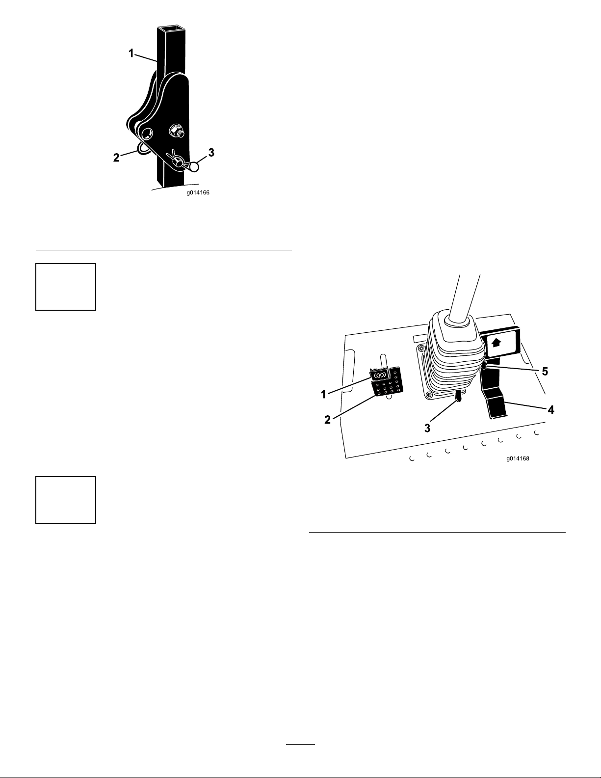
Figure5
1.Rollbar3.Hairpincotterpin
2.Pin
4
ProductOverview
Controls
Becomefamiliarwithallthecontrolsbeforeyoustartthe
engineandoperatethemachine.
TractionPedal
Thetractionpedal(Figure6)controlstheforwardandreverse
operation.Pressthetopofthepedaltomoveforwardandthe
bottomtomoverearward.Groundspeeddependsonhow
faryoupressthepedal.Fornoload,maximumgroundspeed,
fullypressthepedalwhilethethrottleisintheFastposition.
Tostop,reducefootpressureonthetractionpedalandallow
ittoreturntothecenterposition.
Note:Foremergencystops,presstherearofthetraction
pedal(reverse)tostopthemachinequickly.
CheckingtheTirePressure
NoPartsRequired
Procedure
Thetiresareoverinatedforshipping.Therefore,release
someoftheairtoreducethepressure.Thecorrectair
pressurefornon-cabmodelsis103kPa(15psi)inthefront
tiresand172kPa(25psi)inthereartires.Ifacabisinstalled
onthemachine,thefrontandreartiresshouldbeinatedto
172kPa(25psi).
5
CheckingtheFluidLevels
NoPartsRequired
Procedure
1.Checkthehydraulicuidlevelbeforestartingthe
engine,refertoCheckingtheHydraulicFluidLevelin
theMaintenanceSection.
2.Checktheengineoillevelbeforestartingtheengine,
refertoCheckingtheEngineOilLevelinthe
MaintenanceSection.
3.Checkthecoolingsystembeforestartingthe
engine;refertoCheckingtheCoolingSysteminthe
MaintenanceSection.
Figure6
1.Parkingbrake4.Tractionpedal
2.Brakepedal
3.Tiltsteeringpedal
5.Speedlimiter
SpeedLimiter
Thespeedlimiterlever(Figure6)canbeippedforwardto
limitthetractionspeedwhileoperating.
BrakePedal
Thebrakepedalisusedinconjunctionwiththebrakepedal
latchtoengageanddisengagetheparkingbrake(Figure6)To
stopthemachine,releasethetractionpedalandallowitto
returntothecenterposition.Thebrakecanassistinstopping
inanemergencysituation.
16
Page 17
ParkingBrake
ThrottleLever
Toengagetheparkingbrake,pushdownonthebrakepedal
andpressthetopforwardtolatch(Figure6).T oreleasethe
parkingbrake,pressthebrakepedaluntiltheparkingbrake
latchretractswithoutcontactingthelockingmechanism.
TiltSteeringPedal
Totiltthesteeringwheeltowardsyou,pressthefootpedal
down,andpullthesteeringtowertowardyoutothemost
comfortablepositionandthenreleasethepedal(Figure6).T o
movethesteeringwheelawayfromyou,pressthefootpedal
andreleaseitwhenthesteeringwheelreachesthedesired
operatingposition.
IgnitionSwitch
Theignitionswitchhasthreepositions:Off,On/Preheat,
andStart(Figure7).
Thethrottlelever(Figure7)controlsthespeedoftheengine.
MovingthethrottleleverforwardtowardtheFastposition
increasestheenginespeed.Movingitrearwardtowardthe
Slowpositiondecreasestheenginespeed.Thethrottle
controlsthespeedofthePTOand,inconjunctionwiththe
tractionpedal,controlsgroundspeedofthemachine.Always
runthemachinewiththethrottleintheFastpositionwhen
operatingattachments.
PowerTakeOff(PTO)Switch
Thepowertakeoff(PTO)switchstartsandstopsthe
attachment(Figure7).
SteeringSelectorSwitch(4wheeldrive
modelsonly)
Pressthesteeringselectorswitchtothereartoengage4wheel
steeringandforwardtoreturnto2wheelsteering(Figure7).
HourMeter
Thehourmeter(Figure7)recordsthenumberofhoursthe
enginehasoperated.Itoperateswhenthekeyswitchisin
theRunposition.Usethesetimesforschedulingregular
maintenance.
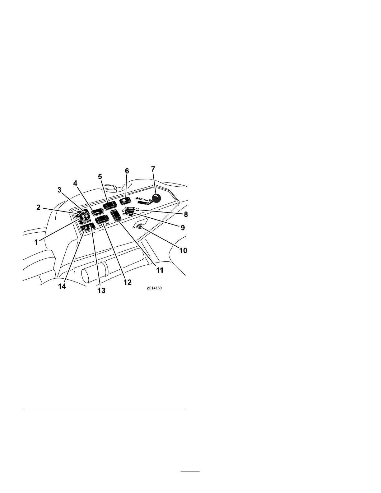
Figure7
1.Powertakeoff(PTO)
Switch
2.Oilpressurewarninglight
3.Chargeindicatorlight
4.Hourmeter
5.Differentiallockswitch
(optional-2wheeldrive
only)
6.Steeringselectorswitch(4
wheeldriveonly)
7.Throttlelever14.Enginecoolant
8.Diagnosticlight(4wheel
driveonly)
9.Ignitionswitch
10.Powerpoint
11.Optionalswitchlocation
12.Deckliftswitch
13.Glowpluglight
temperaturewarning
light
DiagnosticLight(4wheeldrivemodels
only)
Itwillilluminateshouldasystemfaultberecognized(Figure
7).
DifferentialLockSwitch(optional-2
wheeldrivemodelsonly)
Pressthefrontoftheswitchandholditdowntoengagethe
differentiallock(Figure7).
GlowPlugLight(OrangeLight)
Theglowplugindicatorlight(Figure7)turnsonwhenthe
ignitionswitchisturnedtotheOnposition.Itremainslit
for6seconds.Whenthelightturnsoff,theengineisready
tobestarted.
EngineCoolantTemperatureWarning
Light
Thislightglowsandthecuttingbladesstopiftheengine
coolanttemperatureishigh(Figure7).Ifthemachineisnot
stoppedandthecoolanttemperaturerisesanother-7°C(20°
F),theenginewillstop.
Important:Iftheattachmentshutsdownandthe
temperaturewarninglightison,pushPTOknobdown,
drivetoasafeatarea,movethethrottlelevertothe
Slowposition,allowthetractionpedaltomovetothe
neutralposition,andengagetheparkingbrake.Allow
theenginetoidleforseveralminuteswhileitcoolstoa
safelevel.Stoptheengineandcheckthecoolingsystem;
refertoCheckingtheCoolingSystem.
17
Page 18

ChargeIndicator
Illuminateswhenthechargingsystemcircuitmalfunctions
(Figure7).
OilPressureWarningLight
Theoilpressurewarninglight(Figure7)glowswhentheoil
pressureinenginedropsbelowasafelevel.Iflowoilpressure
everoccurs,stoptheengineimmediatelyanddeterminethe
cause.Repairthedamagebeforestartingtheengineagain.
FuelGauge
Thefuelgauge(Figure8)indicatesthefuellevelremaining
inthefueltank.
Figure9
Figure8
1.Fuelgauge2.Fueltankcap
CabControls
Model31222only
WindShieldWiper/WasherSwitch
Presstherearoftheswitchtoactivatethewindshieldwipers
(Figure9)andthefrontofswitchtoactivatethewindshield
washer.Releasetheswitchtoturnoffthewasher.
1.Windshieldwiper/washer
switch
2.Airconditioningswitch4.Temperaturecontrol
FanControl
3.Fancontrol
Rotatethefancontrolknobtoregulatethespeedofthefan
(Figure9).
TemperatureControl
Rotatethetemperaturecontrolknobtoregulatetheair
temperatureinthecab(Figure9).
HeaterShut-offValve
Closingtheheatershut-offvalve,locatedinengine
compartment(
Figure10),willmaximizetheairconditioner
capacitytothecabduringthesummer.Duringthefall
conversion,fullyopenthevalve.
AirConditioningSwitch
Pressthefrontoftheswitchtoactivatetheairconditioning
(Figure9)andtherearoftheswitchtoturnofftheair
conditioning.
18
Page 19

Figure10
1.Heatershut-offvalve
Specications
Note:Specicationsanddesignaresubjecttochange
withoutnotice.
Length
Width(RearWheels)147.3cm(58inches)
Height,Model31223(withRoll
BarUp)
Height,Model31223(withRoll
BarDown)
Height,Model31222
Weight,Model31222
Weight,Model31223
Attachments/Accessories
AselectionofToroapprovedattachmentsandaccessoriesis
availableforusewiththemachinetoenhanceandexpand
itscapabilities.ContactyourAuthorizedServiceDealeror
Distributororgotowww .Toro.comforalistofallapproved
attachmentsandaccessories.
241.3cm(95inches)
198cm(78inches)
137.2cm(54inches)
218.4cm(86inches)
1361kg(3000lb)
1134kg(2500lb)
Operation
Note:Determinetheleftandrightsidesofthemachine
fromthenormaloperatingposition.
CAUTION
Thismachineproducessoundlevelsinexcessof80
dBAattheoperatorsearandcancausehearingloss
throughextendedperiodsofexposure.
Wearhearingprotectionwhenoperatingthis
machine.
AddingFuel
Useonlyclean,freshdieselfuelorbiodieselfuelswithlow
(<500ppm)orultralow(<15ppm)sulfurcontent.The
minimumcetaneratingshouldbe40.Purchasefuelin
quantitiesthatcanbeusedwithin180daystoensurefuel
freshness.
Fueltankcapacity:51.1liters(13.5USgallons)
Usesummergradedieselfuel(No.2-D)attemperatures
above-7°C(20°F)andwintergrade(No.1-DorNo.
1-D/2-Dblend)belowthattemperature.Useofwintergrade
fuelatlowertemperaturesprovideslowerashpointand
coldowcharacteristicswhichwilleasestartingandreduce
fuellterplugging.
Useofsummergradefuelabove-7°C(20°F)willcontribute
towardlongerfuelpumplifeandincreasedpowercompared
towintergradefuel.
Important:Donotusekeroseneorgasolineinsteadof
dieselfuel.Failuretoobservethiscautionwilldamage
theengine.
WARNING
Fuelisharmfulorfatalifswallowed.Long-term
exposuretovaporscancauseseriousinjuryand
illness.
•Avoidprolongedbreathingofvapors.
•Keepfaceawayfromnozzleandfueltankor
conditioneropening.
•Keepfuelawayfromeyesandskin.
BiodieselReady
Thismachinecanalsouseabiodieselblendedfuelofup
toB20(20%biodiesel,80%petrodiesel).Thepetrodiesel
portionshouldbeloworultralowsulfur.Observethe
followingprecautions:
•Thebiodieselportionofthefuelmustmeetspecication
ASTMD6751orEN14214.
•TheblendedfuelcompositionshouldmeetASTMD975
orEN590.
•Paintedsurfacesmaybedamagedbybiodieselblends.
19
Page 20

•UseB5(biodieselcontentof5%)orlesserblendsincold
weather.
•Monitorseals,hoses,gasketsincontactwithfuelasthey
maybedegradedovertime.
•Fuellterpluggingmaybeexpectedforatimeafter
convertingtobiodieselblended.
•Contactyourdistributorifyouwishformoreinformation
onbiodiesel.
DANGER
Incertainconditions,fuelisextremelyammable
andhighlyexplosive.Areorexplosionfromfuel
canburnyouandothersandcandamageproperty.
•Fillthefueltankoutdoors,inanopenarea,when
theengineiscold.Wipeupanyfuelthatspills.
•Neverllthefueltankinsideanenclosedtrailer.
FillingtheFuelTank
1.Parkthemachineonalevelsurface.
2.Shuttheengineoffandsettheparkingbrake.
3.Cleanaroundthefueltankcapandremovethecap
(Figure11).
•Neversmokewhenhandlingfuel,andstayaway
fromanopenameorwherefuelfumesmaybe
ignitedbyaspark.
•Storefuelinanapprovedcontainerandkeepit
outofthereachofchildren.Neverbuymore
thana30-daysupplyoffuel.
•Donotoperatewithoutentireexhaustsystemin
placeandinproperworkingcondition.
DANGER
Incertainconditionsduringfueling,static
electricitycanbereleasedcausingasparkwhich
canignitethefuelvapors.Areorexplosionfrom
fuelcanburnyouandothersandcandamage
property.
•Alwaysplacefuelcontainersonthegroundaway
fromyourvehiclebeforelling.
•Donotllfuelcontainersinsideavehicleoron
atruckortrailerbedbecauseinteriorcarpets
orplastictruckbedlinersmayinsulatethe
containerandslowthelossofanystaticcharge.
•Whenpractical,removeequipmentfromthe
truckortrailerandrefueltheequipmentwithits
wheelsontheground.
•Ifthisisnotpossible,thenrefuelsuch
equipmentonatruckortrailerfromaportable
container,ratherthanfromafueldispenser
nozzle.
•Ifafueldispensernozzlemustbeused,keepthe
nozzleincontactwiththerimofthefueltank
orcontaineropeningatalltimesuntilfuelingis
complete.
Figure11
1.Fuelgauge
2.Fueltankcap
Important:Donotopenthefueltankwhen
parkedonahill.Thefuelcouldspillout.
4.Addfueltothefueltank,untilthelevelisevenwith
thebottomofthellerneck.Donotoverllthefuel
tank.
5.Installthefueltankcapandsecure.Wipeupanyfuel
thatmayhavespilled.
Note:Ifpossible,llthefueltankaftereachuse.Thiswill
minimizepossiblebuildupofcondensationinsidethefuel
tank.
UsingtheRolloverProtection System(ROPS)
•Keeptherollbarintheraisedandlockedpositionand
usetheseatbeltwhenoperatingthemachine.
•Becertainthattheseatbeltcanbereleasedquicklyin
theeventofanemergency.
•Beawarethereisnorolloverprotectionwhentheroll
barisdown.
•ChecktheareaofoperationandneverfoldtheROPSin
areaswherethereareslopes,dropoffsorwater.
•Lowertherollbaronlywhenabsolutelynecessary.Do
notweartheseatbeltwiththerollbarfoldeddown.
•Checkcarefullyforoverheadclearances(i.e.branches,
doorways,electricalwires)beforedrivingunderany
objectsanddonotcontactthem.
20
Page 21

WARNING
Toavoidinjuryordeathfromrollover:keepthe
rollbarintheraisedlockedpositionandusethe
seatbelt.
Ensurethattheseatplateissecuredwiththeseat
latch.
WARNING
Thereisnorolloverprotectionwhentherollbaris
inthedownposition.
•Lowertherollbaronlywhenabsolutely
necessary.
•Donotweartheseatbeltwhentherollbaris
inthedownposition.
•Driveslowlyandcarefully.
•Raisetherollbarassoonasclearancepermits.
•Checkcarefullyforoverheadclearances(i.e.
branches,doorways,electricalwires)before
drivingunderanyobjectsanddonotcontact
them.
1.Tolowertherollbar,removethehairpincotters,push
therollbarforwardagainstthesprings,andremove
thetwopins(Figure12).
Important:Ensurethattheseatissecuredwith
theseatlatch.
4.Toraisetherollbar,removethehairpincotterpinsand
removethetwopins(Figure12).
5.Raisetherollbartotheuprightpositionandinstallthe
twopinsandsecurethemwiththehairpincotterpins
(Figure12).
Important:Alwaysusetheseatbeltwhentherollbar
isintheraisedandlockedposition.Donotusetheseat
beltwhentherollbarisintheloweredposition.
ThinkSafetyFirst
Pleasereadallsafetyinstructionsandsymbolsinthesafety
section.Knowingthisinformationcouldhelpyouor
bystandersavoidinjury.
DANGER
Operatingonwetgrassorsteepslopescancause
slidingandlossofcontrol.
Wheelsdroppingoveredgescancauserollovers,
whichmayresultinseriousinjury,deathor
drowning.
Thereisnorolloverprotectionwhentherollbaris
down.
Alwayskeeptherollbarintheraisedandlocked
positionandusetheseatbelt.
Figure12
1.Pin3.Rollbar,raisedposition
2.Hairpincotter4.Rollbar,loweredposition
2.Lowertherollbartothedownposition(Figure12).
3.Installthetwopinsandsecurethemwiththehairpin
cotterpins(Figure12).
Readandfollowtherolloverprotectioninstructions
andwarnings.
Toavoidlossofcontrolandpossibilityofrollover:
•Donotoperateneardrop-offsornearwater.
•Reducespeedanduseextremecautionon
slopes.
•Avoidsuddenturnsorrapidspeedchanges.
CAUTION
Thismachineproducessoundlevelsinexcessof
80dBAattheoperatorsearandcancausehearing
lossthroughextendedperiodsofexposure.
Wearhearingprotectionwhenoperatingthis
machine.
StartingandStoppingthe Engine
StartingtheEngine
1.Raisetherollbarupandlockitintoplace,sitonthe
seat,andfastentheseatbelt.
21
Page 22

2.Makesurethetractionpedalisintheneutralposition.
3.Settheparkingbrake.
4.MovethePTO(powertakeoff)switchtotheoff
position(Figure13).
Note:Additionalstartingcyclesmayberequired
whenstartingtheengineforthersttimeafterthefuel
systemhasbeencompletelydrained.
8.LeavethethrottlemidwaybetweentheSlowandFast
positionsuntiltheengineandhydraulicsystemwarm
up.
Important:Whenengineisstartedfortherst
time,orafteranengineoilchange,oranoverhaul
oftheengine,transmission,orwheelmotor,
operatethemachinewiththethrottleleverinthe
Slowpositioninboththeforwardandreverse
directionsforonetotwominutes.Alsooperatethe
liftleverandPTOlevertoensureproperoperation
ofallparts.Thenshuttheengineoffandcheck
uidlevels,checkforoilleaks,looseparts,and
anyothernoticeablemalfunctions.
Figure13
1.Powertakeoffswitch
(PTO)
2.Ignitionswitch4.Throttlelever
5.MovethethrottlelevermidwaybetweentheFastand
Slowpositions(Figure13).
6.TurntheignitionkeyclockwisetotheRunposition
(Figure14).
Theglowpluglightwillturnonfor6seconds.
3.Glowpluglight
CAUTION
Shuttheengineoffandwaitforallmoving
partstostopbeforecheckingforoilleaks,
looseparts,orothermalfunctions.
StoppingtheEngine
1.DisengagethePTO,makesurethetractionpedalisin
theneutralposition,settheparkingbrake,andmove
thethrottlelevertotheSlowposition.
2.Lettheengineidlefor60seconds.
3.TurntheignitionkeytotheOffposition(Figure14).
Waitforallmovingpartstostopbeforeleavingthe
operatingposition.
4.Removethekeybeforetransportingorstoringmachine.
Important:Makesuretoremovethekeyasthe
fuelpumporaccessoriesmayrunandcausethe
batterytolosecharge.
CAUTION
Childrenorbystandersmaybeinjuredifthey
moveorattempttooperatethetractorwhile
itisunattended.
Figure14
1.Start3.Off
2.Run/glowplug4.Glowplugindicatorlight
7.Aftertheglowplugindicatorlightgoesout,turnthe
keytotheStartposition.Whentheenginestarts
releasethekey.
Important:Usestartingcyclesofnomorethan
15secondsperminutetoavoidoverheatingthe
startermotor.
Alwaysremovetheignitionkeyandsetthe
parkingbrakewhenleavingthemachine
unattended,evenifjustforafewminutes.
DrivingtheMachine
Thethrottlecontrolregulatestheenginespeedasmeasured
inrpm(revolutionsperminute).Placethethrottlecontrolin
theFastpositionforbestperformance.Alwaysoperateinthe
Fastthrottlepositionwhenoperatingattachments.
22
Page 23

SteeringSelection(4wheel
StoppingtheMachine
drivemodelsonly)
Formaximumtrimmingandminimumturfdamagethe
machineshouldalwaysbeoperatedin4wheelsteering.
However,whenitisdesiredtotransportthemachineonroads
ortrails,themachinecanbeswitchedinto2wheelsteering.
Figure15
1.Steeringselectorswitch
Switchingfrom4wheelsteeringto2
wheelsteering
Tostopthemachine,releasethetractionpedaltotheneutral
position.
Settheparkingbrakewheneveryouleavethemachine.
Remembertoremovethekeyfromtheignitionswitch.
CAUTION
Childrenorbystandersmaybeinjuredifthey
attempttomoveoroperatethetractorwhileitis
unattended.
Alwaysremovetheignitionkeyandsettheparking
brakewhenleavingthemachineunattended,even
ifjustforafewminutes.
OperatingaMower DeckorAttachment (Optional)
RaisingandLoweringthe
Mower/Attachment
Thedeckliftswitchraisesandlowersthemower
deck/attachment(Figure16).Theenginemustberunning
foryoutousethisswitch.
Pressthesteeringselectorswitch(Figure15)totheforward
position.Ifthewheelsarenotalignedintheforwardposition,
thegreenlightwillashandthemachinewillremainin
4wheelsteeringuntilthefourtiresaredirectedstraight
ahead.Theoperatorshouldturnthesteeringwheelslowlyto
straightenoutthewheelsuntilthegreenlightceasestoash
andremainsON.Whentheswitchlightissolidgreen,the
machineisin2wheelsteering.
Note:Ifthesteeringwheelisturnedtoobriskly,steering
misalignmentmayoccur.
Switchingfrom2wheelsteeringto4
wheelsteering
Pressthesteeringselectorswitch(Figure15)totherearward
position.Ifthefrontwheelsarenotalignedintheforward
position,thegreenlightwillashandthemachinewillremain
in2wheelsteeringuntilthefourtiresaredirectedstraight
ahead.Theoperatorshouldturnthesteeringwheelslowlyto
straightenoutthewheelsuntilthegreenlightceasestoash
andremainsOFF .Ifthesteeringwheelisturnedtoobriskly,
steeringmisalignmentmayoccur.Whentheswitchlightis
continuouslyOFF,themachineisin4wheelsteering.
Figure16
1.Deckliftswitch
•Tolowerthemowerdeck/attachment,pushtheswitch
forward.
•Toraisethemoverdeck/attachment,pushtheswitch
rearward.
Important:Donotcontinuetoholdtheswitchback
afterthemower/attachmenthasfullyraised.Doingso
willdamagethehydraulicsystem.
Note:Ifthesteeringsystemismisalignedafterrepeated
2wheelsteeringto4wheelsteeringengagements,referto
CorrectingSteeringMisalignmentintheMaintenanceSection.
Note:Tolockthemowerdeck/attachmentinaraised
position,raisethedeckpastthe15cm(6inch)position,
removetheheightofcutstoppin(refertoAdjustingthe
23
Page 24

Height-of-Cut),andplacethepininthe15cm(6inch)
height-of-cutposition(Figure18).
EngagingthePowerTakeOff(PTO)
Thepowertakeoff(PTO)switchstartsandstopsthemower
bladesandsomepoweredattachments.
1.Iftheengineiscold,allowtheenginetowarmup5to
10minutesbeforeengagingthePTO .
2.Whileseatedintheseat,makesurethetractionpedalis
intheneutralpositionandtheengineisatfullthrottle.
3.PulluponthePTOswitchtoengageit(
Figure17).
AdjustingtheHeight-of-Cut
Theheight-of-cutisadjustedfrom2.5to15.8cm(1to
6inches)in6mm(1/4inch)incrementsbyrelocatingthe
stoppinintodifferentholelocations.
1.Withtheenginerunning,pushbackonthedecklift
switchuntilthemowerdeckisfullyraisedandrelease
theswitchimmediately(
2.Toadjust,rotatethestoppinuntilthenubonitlines
upwiththeslotsintheholesintheheight-of-cut
bracketandremoveit(Figure18).
3.Selectaholeintheheight-of-cutbracketcorresponding
totheheight-of-cutdesired,insertthepin,androtateit
downtolockitinplace(Figure18).
Note:Therearefourrowsofholepositions(Figure
18).Thetoprowgivesyoutheheightofcutlisted
abovethepin.Thesecondrowdowngivesyouthe
heightlistedplus6mm(1/4inch).Thethirdrow
downgivesyoutheheightlistedplus12mm(1/2inch).
Thebottomrowgivesyoutheheightlistedplus18mm
(3/4inch).Forthe15.8cm(6inch)positionthereis
onlyonehole,locatedinthesecondrow .Thisdoesnot
add6mm(1/4inch)tothe15.8cm(6inch)position.
Figure18).
Figure17
1.PTOswitch
DisengagingthePTO
Todisengage,pushthePTOswitchtotheoffposition.
Figure18
1.Stoppin
4.Adjusttheanti-scalprollersandskidsasrequired.
24
Page 25

TheSafetyInterlockSystem
CAUTION
Ifthesafetyinterlockswitchesaredisconnectedor
damagedthemachinecouldoperateunexpectedly
causingpersonalinjury.
•Donottamperwiththeinterlockswitches.
•Checktheoperationoftheinterlockswitches
dailyandreplaceanydamagedswitchesbefore
operatingthemachine.
5.Withoutanoperatorontheseat,disengagetheparking
brake,movethePTOswitchtooff,andallowthe
tractionpedaltoreturntotheneutralposition.Try
startingtheengine;theengineshouldnotcrank.
UsingtheSCMtoDiagnoseSystem
Problems
2wheeldrivemodelsonly
Themachineisequippedwithastandardcontrolmodule
(SCM)monitoringsystemthattracksthefunctionofvarious
keysystems.TheSCMislocatedundertheseat.
UnderstandingtheSafetyInterlock
System
Thesafetyinterlocksystemisdesignedtopreventtheengine
fromstartingunless:
•Youaresittingontheseatortheparkingbrakeisengaged.
•Thepowertakeoff(PTO)isdisengaged.
•Thetractionpedalisintheneutralposition
•Theenginetemperatureisbelowthemaximumoperating
temperature.
Thesafetyinterlocksystemalsoisdesignedtostoptheengine
whenthetractionpedalismovedfromtheneutralposition
withtheparkingbrakeengaged.Ifyourisefromtheseat
whenthePTOisengagedthereisa1seconddelayandthen
theenginestops.
TestingtheSafetyInterlockSystem
ServiceInterval:Beforeeachuseordaily
Testthesafetyinterlocksystembeforeyouusethemachine
eachtime.Ifthesafetysystemdoesnotoperateasdescribed
below,haveanAuthorizedServiceDealerrepairthesafety
systemimmediately.
1.Sittingontheseat,engagetheparkingbrakeandmove
thePTOtoon.Trystartingtheengine;theengine
shouldnotcrank.
2.Sittingontheseat,engagetheparkingbrakeandmove
thePTOtooff.Engagethetractionpedal.Trystarting
theengine;theengineshouldnotcrank.
3.Sittingontheseat,engagetheparkingbrake,move
thePTOswitchtooffandallowthetractionpedalto
returntotheneutralposition.Nowstarttheengine.
Whiletheengineisrunning,releasetheparkingbrake,
engagethePTOandriseslightlyfromtheseat.Ontwo
wheeldrivemachines,theengineshouldstopwithin2
seconds.Onfourwheeldrivemachines,themower
deckwillshutoff.Theenginewillcontinuetorun.
4.Withoutanoperatorontheseat,engagetheparking
brake,movethePTOswitchtooffandmovethe
tractionpedaltotheneutralposition.Nowstartthe
engine.Whiletheengineisrunning,engagethetraction
pedal;theengineshouldstopwithin2seconds.
OnthefaceoftheSCMare11LEDsthatilluminateto
indicatevarioussystemconditions.Sevenoftheselightscan
beusedbytheoperatorforsystemdiagnosis.Referto
19foradescriptionofwhateachlightmeans.Fordetails
onusingtherestoftheSCMfunctions,refertotheService
Manual,availablethroughyourAuthorizedToroDistributor.
Figure19
1.Hightemperatureshutdown—theenginetemperaturehas
exceededsafelevelsandtheenginehasbeenshutdown.
Checkthecoolingsystem.
2.Hightemperaturewarning—theenginetemperatureis
approachingunsafelevelsandthePTOhasbeenshut
down.Checkthecoolingsystem.
3.Operatorisintheseat
4.ThePTOisOn
5.Theparkingbrakeisnotengaged
6.ControlsareinNeutral
7.TheSCMisreceivingpowerandisoperational
Figure
UnderstandingtheDiagnostic Light
(4WheelDriveonly)
Themachineisequippedwithadiagnosticlightwhich
indicatesiftheelectroniccontrollersensesanelectronic
malfunction.Thediagnosticlightislocatedonthecontrol
panel(
Figure20).Whentheelectroniccontrolleris
functioningcorrectlyandthekeyswitchismovedtothe
Onposition,thecontrollerdiagnosticlightwillturnON
for3secondsandturnOFFtoindicatethelightisworking
25
Page 26

properly.Ifthemachinekillsthelightwillturnonsteady
untilthekeypositionischanged.Thelightwillblinkifthe
controllerdetectsamalfunctionintheelectricalsystem.The
lightwillstopblinkingandautomaticallyresetwhenthekey
switchisturnedtotheOffpositiononcethefaulthasbeen
resolved.
UsetheDiagnosticACEdisplaytoolandoverlaytohelp
verifyandcorrectelectricalfunctionsofthemachine.Contact
yourTorodistributorforassistance.
CheckingtheInterlock Switches
4WheelDriveonly
Thepurposeoftheinterlockswitchesistopreventtheengine
fromcrankingorstartingunlessthetractionpedalisinthe
NeutralpositionandthePTOisdisengaged.Inaddition,the
engineshouldstopwhenthetractionpedalispressedwith
operatoroffoftheseatoriftheparkingbrakeisleftengaged.
CAUTION
Ifsafetyinterlockswitchesaredisconnectedor
damagedthemachinecouldoperateunexpectedly
causingpersonalinjury.
Figure20
1.Diagnosticlight
Whenthecontrollerdiagnosticlightblinks,oneofthe
followingproblemshasbeendetectedbythecontroller:
•Oneoftheoutputshasbeenshorted.
•Oneoftheoutputsisopencircuited.
Usingthediagnosticdisplay,determinewhichoutputis
malfunctioning;refertoCheckingtheInterlockSwitches.
Ifthediagnosticlightisnotilluminatedwhenthekeyswitchis
intheOnposition,thisindicatesthattheelectroniccontroller
isnotoperating.Possiblecausesareasfollows:
•Thelightisburnedout.
•Fusesareblown.
•Itisnotfunctioningcorrectly.
Checktheelectricalconnections,inputfuses,anddiagnostic
lightbulbtodeterminethemalfunction.Ensurethatthe
loop-backconnectorissecuredtothewireharnessconnector.
•Donottamperwiththeinterlockswitches.
•Checktheoperationoftheinterlockswitches
dailyandreplaceanydamagedswitchesbefore
operatingthemachine.
VerifyingtheInterlockSwitchFunction
1.Parkthemachineonalevelsurface,lowerthe
attachment,stoptheengine,andengagetheparking
brake.
2.Raisetheseat.
3.Locatethewireharnessandconnectorsnearthe
controller(Figure21).
DiagnosticAceDisplay
4WheelDriveonly
Themachineisequippedwithanelectroniccontrollerwhich
controlsmostmachinefunctions.Thecontrollerdetermines
whatfunctionisrequiredforvariousinputswitches(i.e.seat
switch,keyswitch,etc.)andturnsontheoutputstoactuate
solenoidsorrelaysfortherequestedmachinefunction.
Fortheelectroniccontrollertocontrolthemachineas
desired,eachoftheinputswitches,outputsolenoids,and
relaysmustbeconnectedandfunctioningproperly.
26
Page 27

g018321
Figure21
1.Wireharnessandconnectors
4.ConnecttheDiagnosticACEdisplaytoolconnectorto
thediagnosticconnector(
Figure22).
TheDiagnosticACEwillilluminatetheLEDassociated
witheachoftheinputswhenthatinputswitchisclosed.
7.Individually,changeeachoftheswitchesfromopen
toclosed(i.e.,sitonseat,engagetractionpedal,etc.),
andnotethattheappropriateLEDonDiagnosticACE
willblinkonandoffwhencorrespondingswitchis
closed.Repeatthisforallswitchesthatyoucanchange
byhand.
8.IfaswitchisclosedandtheappropriateLEDdoesnot
turnon,checkallwiringandconnectionstotheswitch
and/orchecktheswitchwithanohmmeter.Replace
anydefectiveswitchandrepairanydefectivewiring.
Note:TheDiagnosticACEalsohastheabilitytodetect
whichoutputsolenoidsorrelaysareturnedon.Thisisaquick
waytodeterminethesourceofthemachine’smalfunction.
VerifyingOutputFunction
1.Parkthemachineonalevelsurface,lowerthe
attachment,stoptheengine,andengagetheparking
brake.
2.Raisetheseat.
3.Locatewireharnessandconnectorsnearcontroller.
4.Carefullyunplugloopbackconnectorfromharness
connector.
Note:Makesurecorrectoverlaydecalispositioned
onDiagnosticACEdisplay.
Figure22
1.DiagnosticACE
5.TurnthekeyswitchtotheOnposition,butdonot
startthemachine.
Note:Theredtextontheoverlaydecalreferstoinput
switchesandthegreentextreferstooutputs.
6.The“inputsdisplayed”LED ,onthelowerright
columnoftheDiagnosticACE,shouldbeilluminated.
Ifthe“outputsdisplayed”LEDisilluminated,press
thetogglebutton,onDiagnosticACE,tochangeLED
to“inputsdisplayed”.
5.ConnecttheDiagnosticACEconnectortothe
appropriateharnessconnector.Ifthemachineis
equippedwithafrontattachment,itwillhavetwo
controllers.
Note:Makesurecorrectoverlaydecalispositioned
onDiagnosticACE.
6.TurnthekeyswitchtotheONposition,butdonot
startmachine.
Note:Theredtextontheoverlaydecalreferstoinput
switchesandthegreentextreferstooutputs.
7.The“outputsdisplayed”LED,onlowerrightcolumn
ofDiagnosticACE,shouldbeilluminated.Ifthe
“inputsdisplayed”LEDisilluminated,pressthetoggle
button,ontheDiagnosticACE,tochangetheLEDto
“outputsdisplayed”.
Note:Itmaybenecessarytotogglebetween“inputs
displayed”and“outputsdisplayed”severaltimestodo
thefollowingstep.Totogglebackandforth,press
thetogglebuttononce.Thismaybedoneasoftenas
required.Donotholdthebutton.
8.Sitontheseatandattempttooperatethedesired
functionofthemachine.Theappropriateoutput
LEDsshouldilluminatetoindicatethattheECMis
turningonthatfunction.
Note:IfthecorrectoutputLEDsdonotilluminate,verify
thattherequiredinputswitchesareinthenecessarypositions
toallowthatfunctiontooccur.V erifycorrectswitchfunction.
27
Page 28

IftheoutputLEDsareonasspecied,butthemachinedoes
notfunctionproperly,thisindicatesanon-electricalproblem.
Repairasnecessary.
Note:Ifeachoutputswitchisinthecorrectpositionand
functioningcorrectly,buttheoutputLEDsarenotcorrectly
illuminated,thisindicatesanECMproblem.Ifthisoccurs,
contactyourToroDistributorforassistance.
Important:TheDiagnosticACEdisplaymustnotbe
leftconnectedtothemachine.Itisnotdesignedto
withstandtheenvironmentofthemachine'severyday
use.WhendoneusingtheDiagnosticACE,disconnect
itfromthemachineandconnectloop-backconnector
toharnessconnector.Themachinewillnotoperate
withoutloopbackconnectorinstalledontheharness.
StoretheDiagnosticACEindry,securelocationinthe
shop,notonthemachine.
PositioningtheStandardSeat
ChangingtheSeatSuspension
Theseatcanbeadjustedtoprovideasmoothandcomfortable
ride.Positiontheseatwhereyouaremostcomfortable.
Withoutsittingontheseat,turntheknobinfronteither
directiontoprovidethebestcomfort(Figure23).
Figure24
1.Seatsuspensionknob2.Operatorweightsetting
ChangingtheSeatPosition
Theseatcanmoveforwardandbackward.Positiontheseat
whereyouhavethebestcontrolofthemachineandaremost
comfortable.
1.Toadjust,movetheleversidewaystounlocktheseat
(Figure23).
ChangingtheBackPosition
Thebackoftheseatcanbeadjustedtoprovideacomfortable
ride.Positionthebackoftheseatwhereitismost
comfortable.
Toadjustit,turntheknob,undertheright-sidearmrest,in
eitherdirectiontoprovidethebestcomfort(Figure23).
ChangingtheLumbarSupport
Thebackoftheseatcanbeadjustedtoprovideacustomized
lumbarsupportforyourlowerback.
Toadjustit,turntheknob,undertheleft-sidearmrest,in
eitherdirectiontoprovidethebestcomfort(Figure23).
PositioningtheDeluxeSeat
Figure23
1.Backrestknob3.Lumbarsupport
adjustmentknob
2.Seatsuspensionknob4.Seatpositionadjustment
lever
2.Slidetheseattothedesiredpositionandreleaselever
tolockinposition.
3.Verifythattheseathaslockedintoplacebyattempting
tomoveitbackandforth.
Figure25
1.Fore/Aftadjustmentlever
2.Weightadjustmentlever5.Lumbarsupportadjusting
3.Backrestlockinglever
28
4.Armrestadjustmentknob
knob
Page 29

ChangingtheWeightAdjustment
AdjustingtheArmrests
Theseatcanbeadjustedtoprovideasmoothandcomfortable
ride.
Important:Toadjusttheseatforthedriversweightthe
drivermustbeseatedandtheignitionkeymovedtothe
Onposition.
Theseatisadjustedforthedriver’sweightbypullingor
pressingtheweightadjustmentlever(Figure25).
Thedriver’sweightisadjustedcorrectlywhenthearrowisin
themiddleclearareaoftheviewingwindow .
Withinthisviewingarea,theseatcanbeadjustedtoa
minimumspringmovement.
Whentheminimum/maximumweightadjustmenthasbeen
reached,youcanhearitreachingtheupperorlowerendstop.
Important:Topreventinjurytotheoperatorand/or
damagetothemachine,thesettingforthedriver’s
weightandtheseatmustbecheckedandadjusted
beforethemachineisoperated.
Note:T oavoidcompressordamageduringweight
adjustment,thecompressormustbeoperatednolongerthan
1minute.
Thearmrestscanbefoldedbackifrequiredandtheheight
individuallyadjusted.
Toadjustthearmrestsforheight,separatetheroundcap
(Figure25)fromthecover,loosenthehexagonnut(13mm)
behinditandadjustthearmreststothedesiredpositionand
tightenthenut.Replacethecapontothenut.
WARNING
Donotinstallthearmrestinthelowestpositionas
theseatbeltrollermightnotfunctionproperly.
ChangingtheArmrestAngle
Theangleofthearmrestscanbeadjustedforoperator
comfort.
Toadjusttheangleofthearmrests,turntheadjustmentknob
(Figure25).
Whenturningtheknobtotheoutside(+)thefrontpartof
thearmrestwillbelifted,whenturningtheknobtoinside(-)
itwillbelowered.
ChangingtheBackrestPosition
ChangingtheSeatPosition
Theseatcanmoveforwardandbackward.Positiontheseat
whereyouhavethebestcontrolofthemachineandaremost
comfortable.
1.Toadjust,liftthelevertounlocktheseat(Figure25).
2.Slidetheseattothedesiredpositionandreleaselever
tolockinposition.
3.Verifythattheseathaslockedintoplacebyattempting
tomoveitbackandforth.
Note:Donotoperatethelockingleverwhile
operatingthemachine.
ChangingtheLumbarSupport
Thelumbarsupportincreasesboththeseatingcomfortand
theperformanceofthedriver.
Thebackoftheseatcanbeadjustedtoprovideacustomized
lumbarsupportforyourlowerback.
Byturningtheadjustmentknobupwards,thecurvaturein
theupperpartofthebackrestcushioncanbeadjusted.By
turningtheknobdownwards,thecurvatureinthelowerpart
ofthebackrestcushioncanbeadjusted(
Figure25).
Thebackoftheseatcanbeadjustedtoprovideamore
comfortableride.Positionthebackoftheseatwhereitis
mostcomfortable.
Pullupthelockinglevertoreleasethebackrestcatch(Figure
25).Whenreleasingthebackrestcatch,donotapplyloadto
thebackrestbypressingagainstit.
Byexertingpressureonoroffthefrontorrearoftheseatit
canbemovedtothedesiredposition.Releasethelocking
levertolockthebackrest.
Note:Thebackrestshouldnotbeabletomovetheinto
anotherpositionafterithasbeenlocked.
Raising/LoweringtheSeat
Toaccessthehydraulicandothersystemsundertheseat,you
needtounlatchtheseatandswingitforward.
1.Movetheseatlatch,locatedontheleftsideoftheseat,
rearwardtounlatchtheseatandpullforwardonthe
topoftheseat(Figure26).
0=Nocurvature
1=Maximumcurvatureatthetop
2=Maximumcurvatureatthebottom
29
Page 30

Figure26
4.Rotateeachby-passvalvecounterclockwise1turn
(Figure28).
Thisallowshydraulicuidtoby-passthepump
enablingthewheelstoturn.
Important:Donotrotatetheby-passvalvesmore
than1turn.Thispreventsvalvesfromcomingout
ofthebodyandcausinguidtorunout.
5.Disengagetheparkingbrakebeforepushing.
ChangingtoMachineOperation
Rotateeachby-passvalveclockwise1turnandhandtighten
them(torqueofapproximately8N-m(71in-lb)(Figure28).
1.Seatlatch
2.Tolowertheseat,pullupontheseatlatchreleasebar
andlowertheseatintothelockedposition.
Figure27
1.Seatlatchreleasebar
Note:Donotovertightentheby-passvalves.
Themachinewillnotdriveproperlyunlesstheby-passvalves
areturnedin.
Figure28
1.By-passvalves
PushingtheMachinebyHand
Ifthemachinestalls,runsoutoffuel,etc.youmayneedto
pushit.Todoso,yourstneedtoopenbothofthehydraulic
by-passvalves.
Important:Alwayspushthemachinebyhandand
neveralongdistance.Nevertowthemachinebecause
hydraulicdamagemayoccur.
PushingtheMachine
1.Disengagethepowertakeoff(PTO),turntheignition
keytooffandapplytheparkingbrake.
2.Removethekeyfromtheignitionswitch.Both
by-passvalvesmustbeopened.
3.Lifttheseat.
LoadingMachines
Useextremecautionwhenloadingunitsontrailersortrucks.
Onefullwidthrampthatiswideenoughtoextendbeyond
thereartiresisrecommendedinsteadofindividualrampsfor
eachsideoftheunit(Figure29).Thelowerrearsectionof
thetractorframeextendsbackbetweentherearwheelsand
servesasastopfortippingbackward.Havingafullwidth
rampprovidesasurfacefortheframememberstocontactif
theunitstartstotipbackward.Ifitisnotpossibletouseone
fullwidthramp,useenoughindividualrampstosimulatea
fullwidthcontinuousramp.
Therampshouldbelongenoughsothattheanglesdonot
exceed15degrees(
machinecomponentstogetcaughtastheunitmovesfrom
ramptotrailerortruck.Steeperanglesmayalsocausethe
unittotipbackward.Ifloadingonornearaslope,position
thetrailerortrucksoitisonthedownsideoftheslopeand
30
Figure29).Asteeperanglemaycause
Page 31

therampextendsuptheslope.Thiswillminimizetheramp
angle.Thetrailerortruckshouldbeaslevelaspossible.
TransportingMachines
Important:Donotattempttoturntheunitwhileonthe
ramp;youmaylosecontrolanddriveofftheside.
Avoidsuddenaccelerationwhendrivinguparampand
suddendecelerationwhenbackingdownaramp.Both
maneuverscancausetheunittotipbackward.
WARNING
Loadingaunitontoatrailerortruckincreasesthe
possibilityofbackwardtip-overandcouldcause
seriousinjuryordeath.
•Useextremecautionwhenoperatingauniton
aramp.
•Useonlyasingle,fullwidthramp;Donotuse
individualrampsforeachsideoftheunit.
•Ifindividualrampsmustbeused,useenough
rampstocreateanunbrokenrampsurfacewider
thantheunit.
•Donotexceeda15degreeanglebetweenramp
andgroundorbetweenrampandtrailerortruck.
•Avoidsuddenaccelerationwhiledrivingunitup
aramptoavoidtippingbackward.
WARNING
Drivingonthestreetorroadwaywithoutturn
signals,lights,reectivemarkings,oraslow
movingvehicleemblemisdangerousandcanlead
toaccidentscausingpersonalinjury.
Donotdrivemachineonapublicstreetorroadway
withoutsigns,lights,and/ormarkingsrequiredby
localregulations.
Useaheavy-dutytrailerortrucktotransportthemachine.
Ensurethatthetrailerortruckhasallnecessarylightingand
markingasrequiredbylaw.Pleasecarefullyreadallthesafety
instructions.Knowingthisinformationcouldhelpyouor
bystandersavoidinjury.
Totransportthemachine:
•Ensurethatyourvehicle,hitch,safetychains,andtrailer
areadequatefortheloadyouarepullingandthatthey
meetalllocaltrafcregulationsforyourarea.
•Lockthebrakeandblockthewheels.
•Securelyfastenthemachinetothetrailerortruckwith
straps,chains,cable,orropesasrequiredbylocaltrafc
regulationsinyourarea(Figure30).
•Avoidsuddendecelerationwhilebackingunit
downaramptoavoidtippingbackward.
Figure29
1.Trailer3.Notgreaterthan
2.Fullwidthramp4.Fullwidthramp—sideview
15degrees
31
Page 32

Figure30
1.Fronttie-down2.Reartie-downs
32
Page 33

Maintenance
Note:Determinetheleftandrightsidesofthemachinefromthenormaloperatingposition.
RecommendedMaintenanceSchedule(s)
MaintenanceService
Interval
Aftertherst10hours
Aftertherst50hours
Aftertherst200hours
Beforeeachuseordaily
Every50hours
Every100hours
Every150hours
MaintenanceProcedure
•Checkthealternatorbelttension.
•Checktheairconditioningcompressorbelttension(cabmodels)
•T orquewheellugnuts.
•Changetheengineoilandlter.
•Changethehydraulicoilandlter.
•T estthesafetysystem.
•Checktheoperationoftheinterlockswitches.
•Checktheengineoillevel.
•Checktheenginecoolantlevel.
•Cleantheradiatorwithcompressedair(donotusewater)
•Checkthehydraulicuidlevel.
•Cleantheattachment
•Greasethebearingandbushinggreasettings.
•Checkbatterycableconnections.
•Checkthetirepressure.
•Cleantheairconditioningscreen.(Cleanmorefrequentlyinextremelydustyor
dirtyconditions)
•Checkthealternatorbelttension.
•Checktheairconditioningcompressorbelttension(cabmodels)
•Changetheengineoilandlter.
Every200hours
Every250hours
Every400hours
Every800hours
Every1,500hours
Every2years
Important:Refertoyour
•Inspectcoolingsystemhosesandseals.Replacethemifcrackedortorn.
•T orquewheellugnuts.
•Cleanthecabairlters.(Replacethemiftheyaretornorexcessivelydirty.)
•Cleantheairconditioningcoil.(Cleanmorefrequentlyinextremelydustyordirty
conditions)
•Servicetheaircleaner.(Servicetheaircleanerearlieriftheaircleanerindicator
showsred.Serviceitmorefrequentlyinextremelydirtyordustyconditions.)
•Replacethefuelltercanister.
•Checkthefuellinesandconnections.
•Changethehydraulicoilandlter.
•Inspectenginevalveclearance.RefertoyourEngineOperator'sManual.
•Replacemovinghoses
•Drainandcleanthefueltank.
•Flushandreplacecoolingsystemuid.
Engine Operator's Man ual
foradditionalmaintenanceprocedures.AdetailedService
ManualisalsoavailableforpurchasefromyourAuthorizedToroDistributor.
33
Page 34

DailyMaintenanceChecklist
Duplicatethispageforroutineuse.
Fortheweekof: MaintenanceCheckItem
Mon.Tues.Wed.Thurs.Fri.
CheckSafetyInterlock
Operation
CheckParkingBrake
Operation
CheckFuelLevel
CheckHydraulicOilLevel
CheckEngineOilLevel
CheckCoolingSystemFluid
Level
CheckDrainWater/Fuel
Separator
CheckAirFilterRestriction
Indicator
CheckRadiator&Screenfor
Debris
CheckUnusualEngine
Noises
CheckUnusualOperating
Noises
CheckHydraulicHosesfor
Damage
CheckFluidLeaks
CheckTirePressure
CheckInstrumentOperation
LubricateAllGreaseFittings
Touch-upDamagedPaint
1.Checkglowplugandinjectornozzles,ifhardstarting,excesssmokeorroughrunningisnoted.
3
1
2
Sat.Sun.
2.Immediatelyaftereverywashing,regardlessoftheintervallisted.
3.Ifindicatorshowsred
NotationforAreasofConcern
Inspectionperformedby:
ItemDate
Information
CAUTION
Ifyouleavethekeyintheignitionswitch,someonecouldaccidentlystarttheengineandseriouslyinjure
youorotherbystanders.
Removethekeyfromtheignitionbeforeyoudoanymaintenance.
34
Page 35

Figure31
1
G015806
ServiceIntervalChart
Premaintenance
Procedures
UsingtheHoodPropRod
1.Releasethehoodlatches.
2.Liftuponthehooduntiltheproprodcanbe
positionedbehindtheframetube(Figure32).
3.Lowerthehooduntiltherodisinfrontofandresting
againsttheframetube.
4.Tolowerthehood,raisethehooduntiltheproprod
canberaisedabovetheframetube,thenlowerthe
hood.
5.Securethehoodlatches
Lubrication
GreasingtheBearingsand Bushings
ServiceInterval:Every50hours
Themachinehasgreasettingsthatmustbelubricated
regularlywithNo.2GeneralPurposeLithiumBaseGrease.
Ifthemachineisoperatedundernormalconditions,lubricate
allbearingsandbushingsafterevery50hoursofoperation.
Bearingsandbushingsmustbelubricateddailywhen
operatingconditionsareextremelydustyanddirty.Dusty
anddirtyoperatingconditionscouldcausedirttogetinto
thebearingsandbushings,resultinginacceleratedwear.
Lubricatethegreasettingsimmediatelyaftereverywashing,
regardlessofintervalspecied.
1.Wipethegreasettingscleansoforeignmattercannot
beforcedintothebearingorbushing.
2.Pumpgreaseintothettings.
3.Wipeoffexcessgrease.
1.Proprod
Figure32
35
Page 36

Figure33
(Shownwithmowerdeckinstalled)
36
Page 37

Note:Toaccesstherearsteeringlinkagegreasettings,the
storagecompartmentneedstoberemoved.
Note:Jackthemachineofftheoortoallowbettergrease
migrationthroughboththeupperandlowerkingpin
bushings.Greasemustbeobservedpurgingoutofboththe
topandthebottomoftheaxlecasting/bushingassembly
areasofallfourkingpinassemblies.
Note:Bearinglifecanbenegativelyaffectedbyimproper
washdownprocedures.Donotwashdowntheunitwhenit
isstillhotandavoiddirectinghigh-pressureorhighvolume
sprayatthebearingsorseals.
Figure34
37
Page 38

EngineMaintenance
ServicingtheAirCleaner
ServiceInterval:Every400hours
Checktheaircleanerbodyfordamagewhichcouldcausean
airleak.Replaceifdamaged.Checkthewholeintakesystem
forleaks,damage,loosehoseclampsorseals.
4.Cleanthedirtejectionportlocatedintheremovable
cover.Removetherubberoutletvalvefromthecover,
cleanthecavityandreplacetheoutletvalve.
5.Installthecoverorientingtherubberoutletvalveina
downwardposition—betweenapproximately5:00to
7:00whenviewedfromtheend.
6.Securethelatch.
Servicetheaircleanerlteronlywhentheserviceindicator
Figure35)requiresit.Changingtheairlterbeforeitis
(
necessaryonlyincreasesthechanceofdirtenteringtheengine
whenthelterisremoved.
Important:Besurethecoverisseatedcorrectlyand
sealswiththeaircleanerbody .
1.Releasethelatchsecuringtheaircleanercovertothe
aircleanerbody(
Figure35).
CheckingtheEngineOilLevel
ServiceInterval:Beforeeachuseordaily
Theengineisshippedwithoilinthecrankcase;however,the
oillevelmustbecheckedbeforeandaftertheengineisrst
started.
Thecrankcasecapacityisapproximately5.2liters(5.5quarts)
withthelter.
Usehigh-qualityengineoilthatmeetsthefollowing
specications:
•APIClassicationLevelRequired:CH-4,CI-4orhigher
•Preferredoil:SAE15W-40(above0degreesF)
•Alternateoil:SAE10W-30or5W-30(alltemperatures)
ToroPremiumEngineoilisavailablefromyourdistributorin
either15W -40or10W-30viscosity .
1.Parkthemachineonalevelsurface,stoptheengine,
settheparkingbrakeandremovethekeyfromthe
ignitionswitch.
2.Openthehood.
Figure35
1.Aircleanerservice
indicator
2.Aircleanercover
2.Removethecoverfromtheaircleanerbody.Before
removingthelter,uselowpressureair(40psi,clean
anddry)tohelpremovelargeaccumulationsofdebris
packedbetweenoutsideofthelterandthecanister.
Avoidusinghighpressureairwhichcouldforce
dirtthroughthelterintotheintaketract.
Thiscleaningprocesspreventsdebrisfrommigrating
intotheintakewhenthelterisremoved.
3.Removeandreplacethelter.
Cleaningoftheusedelementisnotrecommendeddue
tothepossibilityofdamagetotheltermedia.Inspect
thenewlterforshippingdamage,checkingthesealing
endofthelterandthebody .Donotuseadamaged
element.Insertthenewlterbyapplyingpressureto
theouterrimoftheelementtoseatitinthecanister.
Donotapplypressuretotheexiblecenterofthe
lter.
3.Aircleanercoverlatch
3.Removethedipstick,wipeitclean,andinstallit(Figure
36).
Figure36
1.Dipstick
2.Oilllcap
38
Page 39

4.Removedipstickandcheckoillevelondipstick.The
oillevelshouldbeuptotheFullmark.
5.IftheoillevelisbelowtheFullmark,removethell
cap(Figure36)andaddoiluntillevelreachestheFull
markondipstick.
Donotoverll.
Important:Besuretokeeptheengineoillevel
betweentheupperandlowerlimitsontheoil
gauge.Enginefailuremayoccurasaresultofover
llingorunderllingtheengineoil.
6.Installtheoilllcapandclosethehood.
ChangingtheEngineOiland Filter
ServiceInterval:Aftertherst50hours
Every150hours
AdjustingtheThrottle
1.Movethethrottleleverforwardtothefrontofthe
controlpanelslotandthenmoveitbackapproximately
3mm(1/8inch)outoftheFASTidledetentposition.
2.Checkthepositionofthespeedcontrolleveronthe
enginefuelinjectionpump.Thespeedcontrollever
shouldbecontactingthehighspeedscrewwhenthe
throttlecontrolleverisintheF AST(detent)position
(Figure38).
1.Removethedrainplug(
intoadrainpan.
2.Whentheoilstops,installthedrainplug.
3.Removetheoillter(Figure37).
4.Applyalightcoatofcleanoiltothenewlterseal.
5.Installthereplacementoilltertothelteradapter.
Turntheoillterclockwiseuntiltherubbergasket
contactsthelteradapter,thentightenthelteran
additional1/2turn.
Important:Donotover-tightenthelter.
6.Addoiltothecrankcase;refertoCheckingtheEngine
OilLevel.
Figure37)andlettheoilow
Figure38
1.Throttlecable
2.Highspeedscrew
3.Ifnecessary,thepositionofthethrottlecontrolcable
jamnutscanbeadjusteduntilspeedcontrollever
contactshighspeedscrewwhenthrottlecontrolleveris
atF AST(detent)position(
thehighspeedscrewonthespeedcontrollever.
3.Speedcontrollever
4.Cablejamnuts
Figure38).Donotadjust
Figure37
1.Oildrainplug2.Oillter
4.Makesurethatthecablejamnutsarefullytightened
aftertheadjustment
39
Page 40

FuelSystem
Maintenance
Note:RefertoAddingFuelforproperfuel
recommendations.
DANGER
Undercertainconditions,dieselfuelandfuel
vaporsarehighlyammableandexplosive.Are
orexplosionfromfuelcanburnyouandothersand
cancausepropertydamage.
•Useafunnelandllthefueltankoutdoors,in
anopenarea,whentheengineisoffandiscold.
Wipeupanyfuelthatspills.
•Donotllthefueltankcompletelyfull.Addfuel
tothefueltankuntilthelevelistothebottom
ofthellerneck.
•Neversmokewhenhandlingfuel,andstayaway
fromanopenameorwherefuelfumesmaybe
ignitedbyaspark.
7.Tightenthedrainplugonthebottomofthelter
canister.
BleedingtheFuelSystem
Youmustbleedthefuelsystembeforestartingtheengineif
anyofthefollowingsituationshaveoccurred:
•Initialstartupofanewmachine.
•Enginehasceasedrunningduetolackoffuel.
•Maintenancehasbeenperformeduponfuelsystem
components;i.e.,lterreplaced,separatorserviced,etc.
1.Parkthemachineonalevelsurfaceandensurethatthe
fueltankisatleasthalffull.
2.Openthehoodandsecureitwiththeproprod.
3.Opentheairbleedscrewonthefuelinjectionpump
(Figure40)witha12mmwrench.
•Storefuelinaclean,safety-approvedcontainer
andkeepthecapinplace.
ServicingtheWaterSeparator
ServiceInterval:Every400hours
Drainthewaterorothercontaminantsfromthewater
separator(
every400hoursofoperation.
1.Placeacleancontainerunderthefuellter.
2.Loosenthedrainplugonthebottomofthelter
1.Waterseparatordrainplug
3.Cleantheareawheretheltercanistermounts.
4.Removetheltercanisterandcleanthemounting
5.Lubricatethegasketontheltercanisterwithcleanoil.
6.Installtheltercanisterbyhanduntilthegasket
Figure39)daily.Replacetheltercanisterafter
canister(Figure39).
Figure39
surface.
contactsmountingsurface,thenrotateitanadditional
1/2turn.
Figure40
1.Bleedscrew
4.TurnthekeyintheignitionswitchtotheOnposition.
Theelectricfuelpumpwillbeginoperation,thereby
forcingairoutaroundtheairbleedscrew .Leavethe
keyintheOnpositionuntilasolidstreamoffuelows
outaroundthescrew .
5.TightenthescrewandturnthekeytotheOffposition.
Note:Normally,theengineshouldstartaftertheabove
bleedingproceduresarefollowed.However,ifenginedoes
notstart,airmaybetrappedbetweeninjectionpumpand
injectors;refertoBleedingAirfromtheInjectors.
BleedingAirfromtheFuel Injectors
Note:Thisprocedureshouldbeusedonlyifthefuelsystem
hasbeenpurgedofairthroughnormalprimingprocedures
40
Page 41

andtheenginewillnotstart;refertoBleedingtheFuel
System.
1.LoosenthepipeconnectiontotheNo.1nozzleand
holderassembly(Figure41).
Figure41
1.Fuelinjectors
2.TurnthekeyinthekeyswitchtotheOnpositionand
watchthefuelowaroundtheconnector.Whenyou
observeasolidowoffuel,turnthekeytotheOff
position.
FuelLinesandConnections
ServiceInterval:Every400hours
Checkthefuellinesandconnectionsevery400hoursor
yearly,whichevercomesrst.Inspectthemfordeterioration,
damage,chafng,orlooseconnections.
3.Tightenthepipeconnectorsecurely.
4.Repeatsteps1through3ontheremainingnozzles.
CleaningtheFuelTank
ServiceInterval:Every2years
Drainandcleanfueltankevery2years.Also,removeand
cleanthein-linestrainersafterdrainingthetank.Useclean
dieselfueltoushoutthetank.
Important:Drainandcleanthetankifthefuelsystem
becomescontaminatedorifthemachineistobestored
foranextendedperiod.
41
Page 42

ElectricalSystem
g014186
1
25
10
25
10
25
15
10
10
Maintenance
Important:Wheneverworkingwiththeelectrical
system,alwaysdisconnectthebatterycables,negative
(-)cablerst,topreventpossiblewiringdamagefrom
short-outs.
CheckingtheFuses
Ifthemachinestopsorhasotherelectricalsystemissues,
checkthefuses.Graspeachfuseinturnandremovethem
oneatatime,checkingtoseeifanyareblown.Ifyouneed
toreplaceafuse,alwaysusethesametypeandamperage
ratedfuseastheoneyouarereplacing,otherwiseyoucould
damagetheelectricalsystem(refertothedecalnexttothe
fusesforadiagramofeachfuseanditsamperage).
Thetractionunitfusesarelocatedundertheseat(Figure42).
Figure43
ServicingtheBattery
ServiceInterval:Every50hours
Keepthetopofthebatteryclean.Ifyoustorethemachinein
alocationwheretemperaturesareextremelyhigh,thebattery
willrundownmorerapidlythanifthemachineisstoredin
alocationwheretemperaturesarecool.
Keepthetopofthebatterycleanbywashingitperiodically
withabrushdippedinammoniaorbicarbonateofsoda
solution.Flushthetopsurfacewithwateraftercleaningit.
Donotremovethellcapswhilecleaningthebattery.
Thebatterycablesmustbetightontheterminalstoprovide
goodelectricalcontact.
WARNING
CALIFORNIA
Proposition65Warning
Figure42
1.Fuseblocklocation
Thecabfusesarelocatedinthefuseboxonthecabheadliner
(Figure43).
Batteryposts,terminals,andrelated
accessoriescontainleadandleadcompounds,
chemicalsknowntotheStateofCalifornia
tocausecancerandreproductiveharm.
Washhandsafterhandling.
Ifcorrosionoccursattheterminals,disconnectthecables,
negative(-)cablerst,andscrapetheclampsandterminals
separately.Reconnectthecables,positive(+)cablerst,and
coattheterminalswithpetroleumjelly.
42
Page 43

WARNING
Batteryterminalsormetaltoolscouldshortagainst
metalmachinecomponentscausingsparks.Sparks
cancausethebatterygassestoexplode,resulting
inpersonalinjury.
•Whenremovingorinstallingthebattery,donot
allowthebatteryterminalstotouchanymetal
partsofthemachine.
•Donotallowmetaltoolstoshortbetween
thebatteryterminalsandmetalpartsofthe
machine.
WARNING
Incorrectbatterycableroutingcoulddamagethe
machineandcablescausingsparks.Sparkscan
causethebatterygassestoexplode,resultingin
personalinjury.
•Alwaysdisconnectthenegative(black)battery
cablebeforedisconnectingthepositive(red)
cable.
DriveSystem
Maintenance
CheckingtheTirePressure
ServiceInterval:Every50hours
Checkthepressureafterevery50operatinghoursormonthly,
whicheveroccursrst.
Maintaintheairpressureinthefrontandreartires.The
correctairpressureis172kPa(25psi)inthereartiresand
103kPa(15psi)inthefronttires.Ifacabisinstalledonthe
machine,thefrontandreartiresshouldbeinatedto172kPa
(25psi).Uneventirepressurecancausepoortractionand
possiblydamagetothetractiondrivecomponents.Checkthe
tireswhentheyarecoldtogetthemostaccuratepressure
reading.
CorrectingSteering Misalignment
FourWheelDriveModels
•Alwaysconnectthepositive(red)batterycable
beforeconnectingthenegative(black)cable.
StoringtheBattery
Ifthemachinewillbestoredmorethan30days,removethe
batteryandchargeitfully.Eitherstoreitonashelforon
themachine.Leavethecablesdisconnectedifitisstoredon
themachine.Storethebatteryinacoolatmospheretoavoid
quickdeteriorationofthechargeinthebattery.Toprevent
thebatteryfromfreezing,makesureitisfullycharged.The
specicgravityofafullychargedbatteryis1.265-1.299.
1.Pressthesteeringselectorswitchtotherearward(four
wheelssteer)position(Figure44).
Figure44
1.Steeringselectorswitch
TwoandFourWheelDriveModels
2.Onapavedordirtsurface,turnthesteeringwheelto
theleftorrightandcontinueturninguntilall4wheels
havestoppedturning.Automaticsynchronizationof
wheelalignmentshouldoccur.
Important:Doingthisprocedureonturfcan
resultinturfdamagedirectlyundereachofthe
turningtires.
43
Page 44

CoolingSystem
G014515
Maintenance
DANGER
Dischargeofhotpressurizedcoolantortouching
hotradiatorandsurroundingpartscancausesevere
burns.
•Donotremovetheradiatorcapwhentheengine
ishot.Alwaysallowtheenginetocoolatleast
15minutesoruntiltheradiatorcapiscool
enoughtotouchwithoutburningyourhand
beforeremovingtheradiatorcap.
3.Installtheexpansiontankcap.
•Donottouchradiatorandsurroundingparts
thatarehot.
DANGER
Therotatingfananddrivebeltcancausepersonal
injury.
•Donotoperatethemachinewithoutthecovers
inplace.
•Keepngers,handsandclothingclearof
rotatingfananddrivebelt.
•Shutofftheengineandremovetheignitionkey
beforeperformingmaintenance.
CAUTION
Swallowingenginecoolantcancausepoisoning.
•Donotswallowenginecoolant.
•Keepoutofreachfromchildrenandpets.
CheckingtheCoolingSystem
Figure45
1.Expansiontank
CleaningtheRadiator
ServiceInterval:Beforeeachuseordaily
Topreventtheenginefromoverheating,theradiatormust
bekeptclean.Normally,checktheradiatordailyand,if
necessary,cleananydebrisofftheseparts.However,itwill
benecessarytocheckandcleantheradiatorfrequentlyin
extremelydustyanddirtyconditions.
Note:Iftheattachmentorengineshutsoffdueto
overheating,rstchecktheradiatorandthewholeradiator
forexcessivebuildupofdebris.
Cleantheradiatorasfollows:
1.Openthehoodandsecuretheproprod.
2.Loosentheangenutsecuringthecleanoutcoverto
theundersideoftherearframe(Figure46).Rotatethe
covertothesidetoexposethecleanoutholeinthe
frame.
ServiceInterval:Beforeeachuseordaily
Thecoolingsystemislledwitha50/50solutionofwater
andpermanentethyleneglycolantifreeze.Checkthelevelof
thecoolantintheexpansiontankatthebeginningofeachday
beforestartingtheengine.Thecapacityofthecoolingsystem
is7.5liters(6quarts).
1.Checkthelevelofthecoolantintheexpansiontank
(
Figure45).Thecoolantlevelshouldbebetweenthe
marksonthesideofthetank.
2.Ifcoolantlevelislow ,removetheexpansiontankcap
andreplenishthesystem.Donotoverll.
Figure46
1.Cleanoutcover
44
Page 45

3.Workingfromthefansideoftheradiator,blowout
1
2
debriswithlowpressure(50psi)compressedair(do
notusewater).Repeatthestepfromthefrontofthe
radiatorandagainfromthefanside.
4.Aftertheradiatoristhoroughlycleaned,cleanout
debristhatmayhavecollectedinthechannelatthe
radiatorbaseandaroundtheframe.Also,cleanout
theenginecompartmentandbrakelinkagetoassure
optimumperformance.
5.Closethecleanoutcoverandsecuretheangenut.
6.Closethehood.
BrakeMaintenance
AdjustingtheServiceBrakes
Adjusttheservicebrakeswhenthereismorethan25mm(1
inch)offreetravelofthebrakepedal,orwhenthebrakes
donotworkeffectively.Freetravelisthedistancethebrake
pedalmovesbeforeyoufeelbrakingresistance.
Note:Usethewheelmotorbacklashtorockthedrums
backandforthtoensurethatthedrumsarefreepriortoand
afteradjustment.
1.Toreducefreetravelofthebrakepedals,tightenthe
brakesbylooseningthefrontnutonthethreadedend
ofthebrakecable(Figure47).
Figure47
1.Brakecables2.Frontnuts
2.Tightentherearnuttomovethecablebackwarduntil
brakepedalshave1.27to1.9cm(1/2to3/4inch)of
freetravel,beforewheellockupisachieved.
3.Tightenthefrontnuts,ensuringthatbothcables
actuatethebrakessimultaneously.
45
Page 46

AdjustingtheParkingBrake
1
4
3
2
Iftheparkingbrakefailstoengage,anadjustmenttothe
brakepawlisrequired.
1.Loosenthe2screwssecuringtheparkingbrakepawl
totheframe(Figure48).
Figure48
1.Brakecables3.Parkingbrakepawl
2.Screws(2)
4.Brakedetent
BeltMaintenance
CheckingtheAlternatorBelt
ServiceInterval:Every100hours
Aftertherst10hours
1.Openthehoodandsecuretheproprod.
2.Checkthetensionofthealternatorbeltbydepressing
it(Figure49)midwaybetweenthealternatorandthe
crankshaftpulleyswith10kg(22lb)offorce.
2.Presstheparkingbrakepedalforwarduntilthebrake
detentcompletelyengagesonthebrakepawl(Figure
48).
3.Tightenthe2screwslockingtheadjustment.
4.Pressthebrakepedaltoreleasetheparkingbrake.
5.Checktheadjustmentandreadjustasrequired.
Figure49
1.Alternator3.Brace
2.Bolt
Thebeltshoulddeect11mm(7/16inch).Ifthe
deectionisincorrect,proceedtostep3.Ifcorrect,
continueoperation
3.Loosentheboltsecuringthebracetothealternator
(Figure49),andthealternatorpivotbolt.
4.Insertaprybarbetweenthealternatorandtheengine
andpryoutonthealternator.
5.Whenyouachievethepropertension,tighten
thealternator,braceandpivotboltstosecurethe
adjustment.
46
Page 47

ControlsSystem
Maintenance
AdjustingtheTractionDrive forNeutral
Note:Ifthemachinehasrecentlyhadthehydraulicoil
changedorthetractionmotorsorhosesreplaced,anyair
trappedinthesystemwillhavetobeworkedoutpriorto
performingthisprocedure.Thiscanbeaccomplishedby
operatingthemachineinforwardandreverseforafew
minutesandthenreplenishingtheoilasrequired.
Whenpositionedonalevelsurface,themachinemustnot
creepwhenthetractionpedalisreleased.Ifitdoescreep,
adjustasfollows:
1.Parkthemachineonalevelsurface,stoptheengine,
andlowertheattachmenttotheoor.
2.Jackuptherearofthemachineuntilthereartiresare
offtheshopoor.Supportthemachinewithjack
standstopreventitfromfallingaccidentally.
Note:On4wheeldrivemodels,thefronttiresmust
alsobeofftheshopoorandsupportedbyjackstands.
WARNING
Theenginemustberunningsothis
adjustmentcanbeperformed.Thiscould
causepersonalinjury.
Keephands,feet,face,andotherbodyparts
awayfromanyhotpartsoftheengineandany
rotatingparts.
3.Starttheengine,setthethrottletotheSlowposition
andobservewhichdirectionthereartiresrotate.
Figure50
1.Transmissioncontrolrods
•Iftheleftreartireisrotatinginreverse,lengthen
therodbyslowlyturningtherodcounter-clockwise
(asviewedfromthefront)untiltheleftreartire
stopsrotatingorminimalrotationisdetectedin
reverse
•Iftheleftreartireisrotatingforward,shortenthe
rodbyslowlyturningtherodclockwise(asviewed
fromthefront)untiltheleftreartirestopsrotating.
4.MovethethrottletotheFastposition.Makesurethe
wheelremainsstoppedorminimalcreepisdetectedin
reverse.Adjustasrequired.
5.Tightenthejamnuts.
6.Repeattheprocedurefortherightreartire,ifrequired,
byusingtherightsidetransmissioncontrolrod.
7.Stoptheengine.Removethejackstandsandlowerthe
machinetotheshopoor.
8.Testdrivethemachinetomakesureitdoesnotcreep.
•Iftheleftreartireisrotating,loosenthejamnuts
ontheleftsidetransmissioncontrolrod(Figure
50).
Note:Theforwardendofthecontrolrodhasa
lefthandthread.Therearendoftherod,which
isconnectedtothetransmission,hasarighthand
thread.
AdjustingtheMaximum GroundSpeed
1.DisengagethePTO,releasethetractionpedaltothe
neutralpositionandsettheparkingbrake.
2.MovethethrottlelevertotheSlowposition,stopthe
engine,removethekey,andwaitforallmovingpartsto
stopbeforeleavingtheoperatingposition.
3.Loosenthejamnutonthestopboltforthetraction
pedal(Figure51).
47
Page 48

Figure51
Figure52
1.Tractionpedal
2.Stopboltw/jamnut
(forward)
3.1.5mm(0.060inch)
4.Stopboltw/jamnut
(reverse)
4.Adjustthestopboltallthewayin(awayfromthe
tractionpedal).
5.Usingyourhand,pushthetractionpedalalltheway
forward,withlightpressure,untilitstopsandholdit
there.Maintainonlylightpressureonthepedalwhen
pushingittothefullforwardposition.
6.Withtheseatintheraisedposition,verifythatyou
arenotoverloadingthelinkagebymakingsure
thetransmissiondoesnotmovewhenthepedalis
depressedtothestop.
7.Adjustthestopboltout(towardsthetractionpedal)
untilthereisagapof1.5mm(0.060inch)betweenthe
headofthestopboltandthebottomofthetraction
pedal.
8.Tightenthejamnuttosecurethestopboltinplace.
9.Thereversestopboltmaybeadjustedifthemaximum
reversespeedisnotacceptable.Forafasterreverse
speed,adjustthestopboltin.Foraslowerreverse
speed,adjustthestopboltout.
1.Speedlimiterlever2.Stopboltw/jamnut
4.Threadthestopboltintoincreasethespeedandout
todecreasethespeed.
5.Tightenthejamnuttolocktheadjustment.
6.Rotatethespeedlimiterleverdown,operatethe
machinetoverifytheadjustmentandreadjustthestop
boltasrequired.
AdjustingtheSpeedLimiter Lever
Thespeedlimiterlever(Figure52)canbeippedforwardto
limitthetractionspeedwhileoperating.
1.DisengagethePTO,releasethetractionpedaltothe
neutralpositionandsettheparkingbrake.
2.MovethethrottlelevertotheSlowposition,stopthe
engine,removethekey,andwaitforallmovingpartsto
stopbeforeleavingtheoperatingposition.
3.Loosenthejamnutonthespeedlimiterstopbolt
(
Figure52).
48
Page 49

HydraulicSystem
Maintenance
Thereservoirislledatthefactorywithapproximately17liters
(18quarts)ofhighqualitytractortransmission/hydraulic
uid.Therecommendedreplacementuidisasfollows:
ToroPremiumTransmission/HydraulicTractorFluid
(Availablein5gallonpailsor55gallondrums.Seeparts
catalogorTorodistributorforpartnumbers.)
Alternateuids:IftheTorouidisnotavailable,Mobil®424
hydraulicuidmaybeused.
Note:Torowillnotassumeresponsibilityfordamagecaused
byimpropersubstitutions.
Note:Manyhydraulicuidsarealmostcolorless,makingit
difculttospotleaks.Areddyeadditiveforthehydraulic
systemoilisavailablein20ml(2/3oz.)bottles.Onebottleis
sufcientfor15-221iters(4-6gallons)ofhydraulicoil.Order
partnumber44-2500fromyourauthorizedTorodistributor.
CheckingtheHydraulic System
ServiceInterval:Beforeeachuseordaily
Checkthelevelofthehydraulicuidbeforetheengineisrst
startedanddailythereafter.
1.Positionthemachineonalevelsurface.Releasethe
tractionpedaltotheneutralpositionandstartthe
engine.RunengineatlowestpossibleRPMtopurge
thesystemofair.DonotengagethePTO.Raise
thedecktoextendliftcylinders,stoptheengine,and
removethekey.
2.Removethehydraulicllcap(Figure53)fromller
neck.
Figure53
1.Dipstick
ChangingtheHydraulicOil AndFilter
ServiceInterval:Aftertherst200hours
Every800hours
1.DisengagethePTO,releasethetractionpedaltothe
neutralpositionandsettheparkingbrake.
2.MovethethrottlelevertotheSlowposition,stopthe
engine,removethekey,andwaitforallmovingpartsto
stopbeforeleavingtheoperatingposition.
3.Placealargepanunderthehydraulicreservoirand
transmissioncaseandremovetheplugs,drainingallof
thehydraulicuid(
Figure54).
3.Removethedipstickandwipeitwithacleanrag
(Figure53).
4.Screwthedipstickallthewayintothellerneck;then
removeitandchecklevelofuid(Figure53).
Iflevelisnotwithinnotchedareaofthedipstick,add
enoughhighqualityhydraulicuidtoraiselevelto
withinthenotchedarea.Donotoverll.
5.Replacethedipstickandthreadthellcapnger-tight
ontollerneck.
6.Checkallhosesandttingsforleaks.
49
Page 50

1.Transmissioncasedrain
plug
2.Filter
Figure54
3.Hydraulicreservoirdrain
CabMaintenance
MaximizingAirConditioner Performance
•Tolimitsolarheating,parkthemachineinashadedarea
orleavethedoorsopenindirectsun.
•Makesuretheheatershut-offvalveisclosed.
•Checktomakesuretheairconditioningscreenisclean.
•Checktomakesuretheairconditioningcondenserns
areclean.
•Operatetheairconditionerbloweratthemidspeed
setting.
•Verifycontinuoussealbetweentheroofandtheheadliner.
Correctasrequired.
•Measuretheairtemperatureatthefrontcenterventin
theheadliner(Typicallystabilizeatlessthanorequalto
50degreesF .)
•RefertotheServiceManualforadditionalinformation.
plug
CleaningtheCabAirFilters
4.Cleantheareaaroundthehydraulicoillterand
removeit(
5.Immediatelyinstallanewhydraulicoillter.
6.Installthehydraulicreservoirandtransmissioncase
drainplugs.
7.Fillthereservoirtotheproperlevel(approximately
17liters[18quarts]);refertoCheckingtheHydraulic
Fluid.
8.Starttheengineandcheckforoilleaks.Allowthe
enginetorunforaboutveminutes,thenshutitoff.
9.Aftertwominutes,checkthelevelofthehydraulic
uid;refertoCheckingtheHydraulicFluid.
Figure54).
ServiceInterval:Every250hours(Replacethemiftheyare
tornorexcessivelydirty.)
1.Removethethumbscrewsandgratesfromoverboth
thein-cabandrearcabairlters(Figure55).
50
Page 51

G009265
1
2
3
G009266
1
2
3
CleaningtheAirConditioning Coil
ServiceInterval:Every250hours(Cleanmorefrequentlyin
extremelydustyordirtyconditions)
1.Stoptheengineandremovethekey.
2.Removethe4screwssecuringthefanandthe
condensercovertothefanmount(Figure56).
3.Carefullyliftthefanoutofthecondensercover.
Figure55
1.Thumbscrew
2.Grate
3.Airlter
2.Cleantheltersbyblowingclean,oilfree,compressed
airthroughthem.
Important:Ifeitherlterhasahole,tear,orother
damage,replaceit.
3.Installtheltersandgrate,securingthemwiththe
thumbscrews.
Figure56
1.Cabinroof
2.Condensercover6.Screw
3.Washer7.Airconditioningcondenser
4.Nut
5.Fan
4.Removethetwonutsandwasherssecuringthefrontof
thecondensercovertothecabroof(Figure56).
5.Unplugthefanwireconnectorslocatedbetweenthe
coverandroof.
6.Removethefanandthecover.
7.RemoveandcleantheA/CCondenserScreen.Refer
toCleaningtheA/CCondenserScreen.
8.Cleantheairconditioningcondenserthoroughlywith
compressedair(Figure56).
9.ReplacetheA/CCondenserScreen.
10.Replacethecondensercoverandfan.Makesureto
connectthefanwiresbeforesecuringthecondenser
cover.
51
Page 52

CleaningtheA/CCondenser Screen
Cleaning
ServiceInterval:Every50hours(Cleanmorefrequentlyin
extremelydustyordirtyconditions)
1.Stoptheengineandremovethekey.
2.Ontherearofthefanmount,rotatethelatchtothe
side(Figure57).
Figure57
1.Latch
3.SlidetheA/Cscreenoutfromundertheair
conditioningcoil(Figure57).
2.A/Cscreen
CleaningtheCab
Important:Donotuseapressurewashertocleanthe
doorandroofsealsofthecab.Pressurewashingcan
breakthesealsandcauseleakage.Usegardenhose
pressure.
WasteDisposal
Engineoil,batteries,hydraulicoil,andenginecoolantare
pollutantstotheenvironment.Disposeoftheseaccordingto
yourstateandlocalregulations.
4.Cleanthescreenthoroughlywithcompressedair
(Figure57).
5.Slidethescreenintothechannelsundertheair
conditioningcoilandrotatethelatchdownward.
52
Page 53

Storage
B.Cleanthebattery,terminals,andpostswithawire
brushandbakingsodasolution.
Engine
1.Draintheengineoilfromtheoilpanandreplacethe
drainplug.
2.Removeanddiscardtheoillter.Installanewlter.
3.Relltheenginewith3.8liters(4quarts)of
recommendedmotoroil.RefertoChangingthe
EngineOil.
4.Starttheengineandrunitatidlespeedfortwominutes.
5.Drainthefuelfromthefueltank,fuellines,pump,
lter,andseparator.Flushthefueltankwithclean
dieselfuelandconnectallfuellines.
6.Thoroughlycleanandservicetheaircleanerassembly.
7.Sealtheaircleanerinletandtheexhaustoutletwith
weatherproofmaskingtape.
8.Checktheoilllercapandfueltankcaptoensurethey
aresecurelyinplace.
Machine
1.Thoroughlycleanthemachine,attachmentandthe
engine,payingspecialattentiontotheseareas:
C.Coatthecableterminalsandbatterypostswith
Grafo112Xskin-overgrease(ToroPartNo.
505-47)orpetroleumjellytopreventcorrosion.
D.Slowlyrechargethebatteryfor24hoursevery60
daystopreventleadsulfationofthebattery.
•Radiatorandradiatorscreen
•Underneaththeattachment
•Undertheattachmentcovers
•PTOshaftassembly
•Allgreasettingsandpivotpoints
•Removethecontrolpanelandcleanoutinsideof
thecontrolbox
•Beneaththeseatplateandtopofthetransmission
2.Checkandadjustfrontandreartirepressure;referto
CheckingTirePressure.
3.Remove,sharpen,andbalancethemowerblades.
Installthebladesandtorquethebladefastenersto
115-149N-m(85-110ft-lb).
4.Checkallfastenersforloosenessandtightenthemas
necessary.
5.Greaseoroilallgreasettings,pivotpoints,and
transmissionby-passvalvepins.Wipeoffanyexcess
lubricant.
6.Lightlysandandusetouchuppaintonpaintedareas
thatarescratched,chippedorrusted.Repairanydents
inthemetalbody.
7.Servicethebatteryandcablesasfollows:
A.Removethebatteryterminalsfromthebattery
posts.
53
Page 54

Notes:
54
Page 55

Notes:
55
Page 56

TheToroTotalCoverageGuarantee
ALimitedWarranty
ConditionsandProductsCovered
TheToroCompanyanditsafliate,ToroWarrantyCompany,pursuant
toanagreementbetweenthem,jointlywarrantyourToroCommercial
product(“Product”)tobefreefromdefectsinmaterialsorworkmanship
fortwoyearsor1500operationalhours*,whicheveroccursrst.This
warrantyisapplicabletoallproductswiththeexceptionofAerators
(refertoseparatewarrantystatementsfortheseproducts).Wherea
warrantableconditionexists,wewillrepairtheProductatnocosttoyou
includingdiagnostics,labor,parts,andtransportation.Thiswarranty
beginsonthedatetheProductisdeliveredtotheoriginalretailpurchaser.
*Productequippedwithanhourmeter.
InstructionsforObtainingWarrantyService
YouareresponsiblefornotifyingtheCommercialProductsDistributoror
AuthorizedCommercialProductsDealerfromwhomyoupurchasedthe
Productassoonasyoubelieveawarrantableconditionexists.Ifyouneed
helplocatingaCommercialProductsDistributororAuthorizedDealer,or
ifyouhavequestionsregardingyourwarrantyrightsorresponsibilities,
youmaycontactusat:
ToroCommercialProductsServiceDepartment
ToroWarrantyCompany
811 1LyndaleAvenueSouth
Bloomington,MN55420-1196
952–888–8801or800–952–2740
E-mail:commercial.warranty@toro.com
OwnerResponsibilities
AstheProductowner,youareresponsibleforrequiredmaintenance
andadjustmentsstatedinyourOperator'sManual.Failuretoperform
requiredmaintenanceandadjustmentscanbegroundsfordisallowinga
warrantyclaim.
ItemsandConditionsNotCovered
Notallproductfailuresormalfunctionsthatoccurduringthewarranty
periodaredefectsinmaterialsorworkmanship.Thiswarrantydoesnot
coverthefollowing:
•Productfailureswhichresultfromtheuseofnon-Tororeplacement
parts,orfrominstallationanduseofadd-on,ormodiednon-T oro
brandedaccessoriesandproducts.Aseparatewarrantymaybe
providedbythemanufactureroftheseitems.
•Productfailureswhichresultfromfailuretoperformrecommended
maintenanceand/oradjustments.Failuretoproperlymaintainyour
ToroproductpertheRecommendedMaintenancelistedinthe
Operator’sManualcanresultinclaimsforwarrantybeingdenied.
•ProductfailureswhichresultfromoperatingtheProductinan
abusive,negligent,orrecklessmanner.
•Partssubjecttoconsumptionthroughuseunlessfoundtobe
defective.Examplesofpartswhichareconsumed,orusedup,
duringnormalProductoperationinclude,butarenotlimitedto,brake
padsandlinings,clutchlinings,blades,reels,rollersandbearings
(sealedorgreasable),bedknives,sparkplugs,castorwheelsand
bearings,tires,lters,belts,andcertainsprayercomponentssuchas
diaphragms,nozzles,andcheckvalves,etc.
•Failurescausedbyoutsideinuence.Conditionsconsideredtobe
outsideinuenceinclude,butarenotlimitedto,weather,storage
practices,contamination,useofunapprovedfuels,coolants,
lubricants,additives,fertilizers,water,orchemicals,etc.
•Failureorperformanceissuesduetotheuseoffuels(e.g.gasoline,
diesel,orbiodiesel)thatdonotconformtotheirrespectiveindustry
standards.
•Normalnoise,vibration,wearandtear,anddeterioration.
•Normal“wearandtear”includes,butisnotlimitedto,damageto
seatsduetowearorabrasion,wornpaintedsurfaces,scratched
decalsorwindows,etc.
Parts
Partsscheduledforreplacementasrequiredmaintenancearewarranted
fortheperiodoftimeuptothescheduledreplacementtimeforthatpart.
Partsreplacedunderthiswarrantyarecoveredforthedurationofthe
originalproductwarrantyandbecomethepropertyofT oro.T orowill
makethenaldecisionwhethertorepairanyexistingpartorassemblyor
replaceit.T oromayuseremanufacturedpartsforwarrantyrepairs.
DeepCycleandLithium-IonBatteryWarranty:
DeepcycleandLithium-Ionbatterieshaveaspeciedtotalnumberof
kilowatt-hourstheycandeliverduringtheirlifetime.Operating,recharging,
andmaintenancetechniquescanextendorreducetotalbatterylife.Asthe
batteriesinthisproductareconsumed,theamountofusefulworkbetween
chargingintervalswillslowlydecreaseuntilthebatteryiscompletelyworn
out.Replacementofwornoutbatteries,duetonormalconsumption,
istheresponsibilityoftheproductowner.Batteryreplacementmaybe
requiredduringthenormalproductwarrantyperiodatowner’sexpense.
Note:(Lithium-Ionbatteryonly):ALithium-Ionbatteryhasapartonly
proratedwarrantybeginningyear3throughyear5basedonthetime
inserviceandkilowatthoursused.RefertotheOperator'sManualfor
additionalinformation.
MaintenanceisatOwner’sExpense
Enginetune-up,lubrication,cleaningandpolishing,replacementoflters,
coolant,andcompletingrecommendedmaintenancearesomeofthe
normalservicesT oroproductsrequirethatareattheowner’sexpense.
GeneralConditions
RepairbyanAuthorizedT oroDistributororDealerisyoursoleremedy
underthiswarranty.
NeitherTheToroCompanynorToroWarrantyCompanyisliablefor
indirect,incidentalorconsequentialdamagesinconnectionwiththe
useoftheToroProductscoveredbythiswarranty ,includingany
costorexpenseofprovidingsubstituteequipmentorserviceduring
reasonableperiodsofmalfunctionornon-usependingcompletion
ofrepairsunderthiswarranty.ExceptfortheEmissionswarranty
referencedbelow,ifapplicable,thereisnootherexpresswarranty .
Allimpliedwarrantiesofmerchantabilityandtnessforuseare
limitedtothedurationofthisexpresswarranty .
Somestatesdonotallowexclusionsofincidentalorconsequential
damages,orlimitationsonhowlonganimpliedwarrantylasts,sothe
aboveexclusionsandlimitationsmaynotapplytoyou.Thiswarranty
givesyouspeciclegalrights,andyoumayalsohaveotherrightswhich
varyfromstatetostate.
Noteregardingenginewarranty:
TheEmissionsControlSystemonyourProductmaybecoveredby
aseparatewarrantymeetingrequirementsestablishedbytheU.S.
EnvironmentalProtectionAgency(EPA)and/ortheCaliforniaAir
ResourcesBoard(CARB).Thehourlimitationssetforthabovedonot
applytotheEmissionsControlSystemWarranty.RefertotheEngine
EmissionControlWarrantyStatementsuppliedwithyourproductor
containedintheenginemanufacturer’sdocumentationfordetails
CountriesOtherthantheUnitedStatesorCanada
CustomerswhohavepurchasedT oroproductsexportedfromtheUnitedStatesorCanadashouldcontacttheirT oroDistributor(Dealer)toobtain
guaranteepoliciesforyourcountry ,province,orstate.IfforanyreasonyouaredissatisedwithyourDistributor'sserviceorhavedifcultyobtaining
guaranteeinformation,contacttheT oroimporter.
374-0253RevB
 Loading...