

Page 1

WHEEL HORSE 6 & 8-SPEED MECHANICAL TRANSMISSION
Table of Contents – Page 1 of 3
FOREWORD
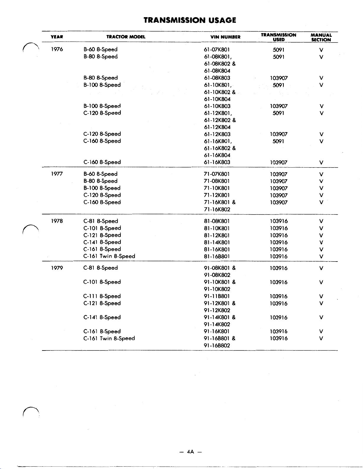
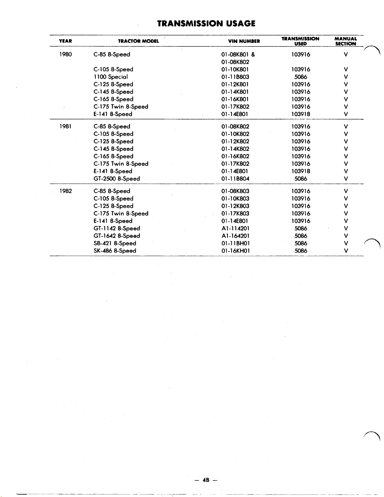
TRANSMISSION USAGE
SECTION I 5003 AND 5010 TRANSMISSIONS
DESCRIPTION
RATIOS
REMOVAL AND REPLACEMENT
REMOVAL:
INSTALLATION:
5003-5010 3-SPEED TRANSMISSION
DISASSEMBLY:
CLEANING, INSPECTION, BEARING AND OIL SEAL REPLACEMENT
ASSEMBLY:
5003 AND 5010 DIFFERENTIAL OVERHAUL
DISASSEMBLY:
CLEANING, INSPECTION, PARTS REPLACEMENT
ASSEMBLY:
5003 AND 5010 SERVICE NOTES
1. TRANSMISSION COVERS
2. #3559 BRAKE SHAFTS
3. SPLINE SHAFT AND MATCHING GEARS
4. #3559 BRAKE SHAFT
5003 - 5010 TRANSMISSION
SECTION II 5053-5058 3-SPEED UNIDRIVE
DESCRIPTION
RATIOS
REMOVAL AND REPLACEMENT
REMOVAL:
INSTALLATION:
DISASSEMBLY:
CLEANING, INSPECTION, BEARING AND OIL SEAL REPLACEMENT
ASSEMBLY:
ASSEMBLY OF 5058 SERIES WITH BEVEL GEAR DIFFERENTIAL
DIFFERENTIAL OVERHAUL STANDARD DIFFERENTIAL
DISASSEMBLY:
STANDARD DIFFERENTIAL
ASSEMBLY:
BEVEL GEAR DIFFERENTIAL
DISASSEMBLY:
ASSEMBLY:
5053 TYPICAL SPUR GEAR DIFFERENTIAL TYPE
5053 TRANSMISSION PARTS LIST
5058 BEVEL GEAR DIFFERENTIAL TYPE
5058 TRANSMISSION PARTS LIST
Page 2

WHEEL HORSE 6 & 8-SPEED MECHANICAL TRANSMISSION
Table of Contents – Page 2 of 3
SECTION III 5060 6-SPEED TRANSMISSION
DESCRIPTION
REMOVAL AND REPLACEMENT
REMOVAL:
INSTALLATION:
5060 6-SPEED TRANSMISSION
DISASSEMBLY:
NEEDLE BEARING REPLACEMENT:
CLUSTER GEAR:
CLEANING, INSPECTION, BEARING AND OIL SEAL REPLACEMENT
ASSEMBLY:
LIMITED SLIP DIFFERENTIA L
DISASSEMBLY:
ASSEMBLY:
5060 TRANSMISSION
5060 TRANSMISSION PARTS LIST
SECTION IV 4-SPEED UNIDRIVE
DESCRIPTION
RATIOS
REMOVAL AND REPLACEMENT
REMOVAL:
INSTALLATION:
4-SPEED UNIDRIVE TRANSMISSION
DISASSEMBLY:
CLEANING, INSPECTION, BEARING AND OIL SEAL REPLACEMENT
ASSEMBLY:
DIFFERENTIAL OVERHAUL 4 PINION DIFFERENTIAL
DISASSEMBLY:
DIFFERENTIAL
ASSEMBLY:
4-SPEED TRANSMISSION
SECTION V 8-SPEED TRANSMISSION
DESCRIPTION
RATIOS
REMOVAL AND REPLACEMENT
REMOVAL:
INSTALLATION:
DISASSEMBLY:
NEEDLE BEARING REPLACEMENT:
CLUSTER GEAR:
CLEANING, INSPECTION, BEARING AND OIL SEAL REPLACEMENT
ASSEMBLY:
8 PINION DIFFERENTIAL
DISASSEMBLY:
Page 3

WHEEL HORSE 6 & 8-SPEED MECHANICAL TRANSMISSION
Table of Contents – Page 3 of 3
SECTION V 8-SPEED TRANSMISSION -Continued
REMOVAL AND REPLACEMENT -Continued
ASSEMBLY:
8-SPEED, 10 PINION LIMITED SLIP DIFF ER ENTIAL
8-SPEED, 4 PINION DIFFERENTIAL 1" AXLES
8-SPEED, 8 PINION DIFFERENTIAL 1-1/8" AXLES
8-SPEED TRANSMISSION
Page 4
MECHANICAL
TRANSMISSION
REPAIR MANUAL
WHEEL
lawn
I
&
garden tractors
Price
$3.50
Page 5
FOREWORD
This
service and repair manual has been compiled to provide
authorized Wheel Horse service personnel with the proper procedures
and techniques for servicing
The following index lists all areas covered.
all
of
the introductory sections first to gain a proper understanding of
Wheel
Horse mechanical transmissions.
It
is
advisable to read
the Wheel Horse mechanical transmission used in each model.
is
The transmission
a sophisticated piece of machinery. Maintain
strict cleanliness control during all stages of service and repair. Even
a small amount of dirt or other contamination can severely damage
the components.
of
Product information and specifications are shown herein as
time
of
change product specifications, designs and standard equipment without
notice and without incurring obligation.
printing. Wheel Horse Products, Inc. reserves the right to
the
Page 6
Page
Page
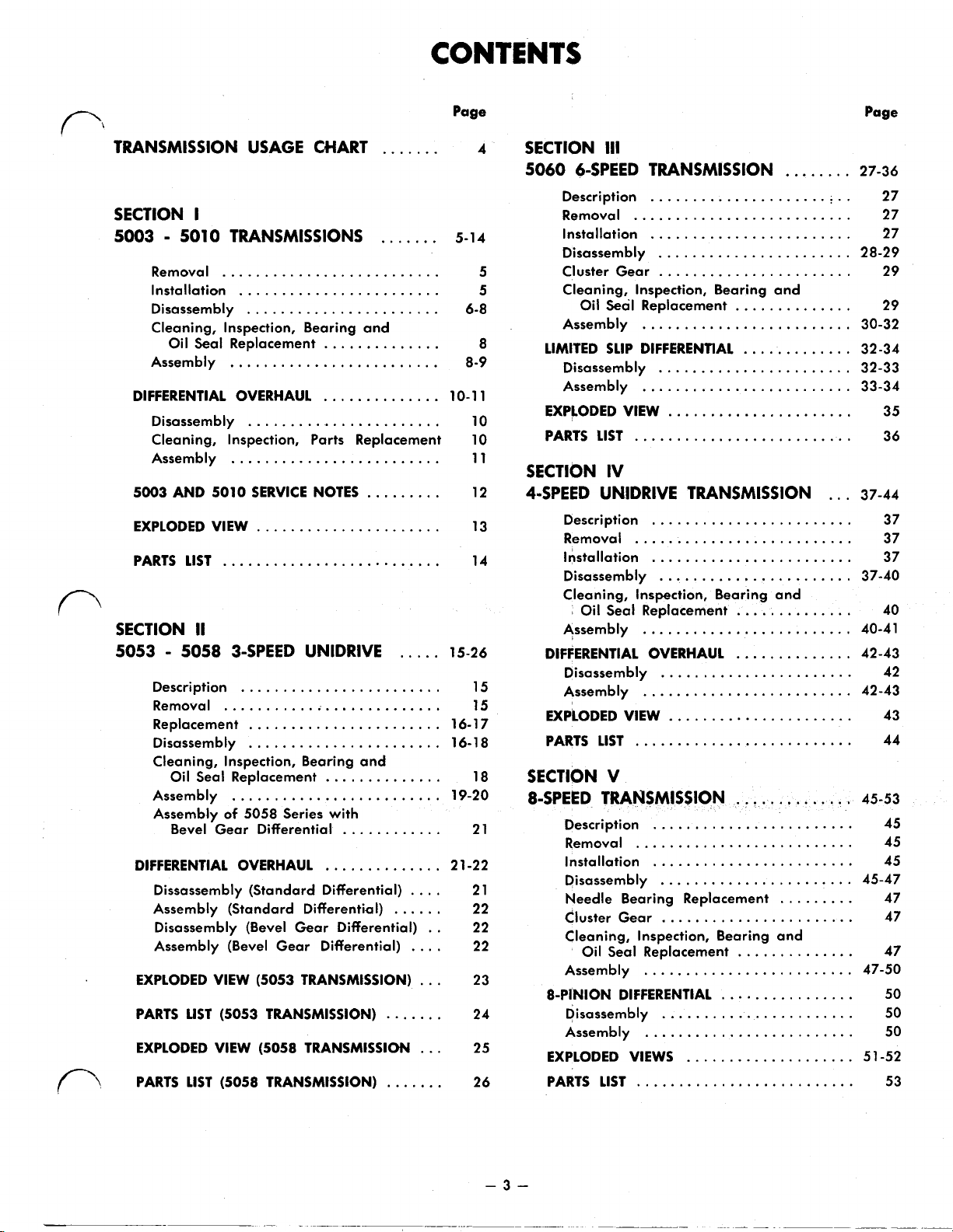
TRANSMISSION USAGE CHART
SECTION
I
5003 5010 TRANSMISSIONS
Removal
Installation
Disassembly
Cleaning. Inspection. Bearing and
Oil Seal Replacement
Assembly
DIFFERENTIAL OVERHAUL
Disassembly
Cleaning. Inspection. Parts Replacement 10
Assembly
5003
AND
EXPLODED VIEW
PARTS
SECTION
..........................
........................
.......................
..............
.........................
..............
.......................
.........................
5010
SERVICE NOTES
......................
LIST
..........................
II
.......
.......
.........
5053 5058 3-SPEED UNlDRlVE
Description
Removal
Replacement
Disassembly
Cleaning, Inspection, Bearing and
Oil Seal Replacement
Assembly
Assembly
Bevel Gear Differential
DIFFERENTIAL OVERHAUL
Dissassembly (Standard Differential)
Assembly (Standard Differential)
Disassembly (Bevel Gear Differential) 22
Assembly (Bevel Gear Differential)
EXPLODED VIEW
PARTS LIST
EXPLODED VIEW (5058 TRANSMISSION
PARTS
LIST
........................
..........................
.......................
.......................
..............
.........................
of
5058
Series with
............
..............
......
(5053
TRANSMISSION)
(5053
TRANSMISSION)
(5058 TRANSMISSION)
.......
.......
.....
....
....
...
...
4
5-1 4
6-8
8-9
10-1
10
11
12
13
14
15-26
15
15
16-1
16-1 8
18
19-20
21
2 1-22
21
22
22
23
24
25
26
SECTION
III
5060 6-SPEED TRANSMISSION
Description
Removal
Installation
Disassembly
5
5
8
1
Cluster Gear
Cleaning. Inspection. Bearing and
Oil
Assembly
LIMITED
Disassembly
Assembly
EXPLODED VIEW
PARTS
LIST
SECTION
........................
..........................
........................
Seal
Replacement
.........................
SLIP
DIFFERENTIAL
.........................
..........................
IV
4-SPEED UNlDRlVE TRANSMISSION
Description
Removal
Installation
Disassembly
Cleaning. Inspection. Bearing and
Oil Seal Replacement
Assembly
DIFFERENTIAL OVERHAUL
Disassembly
Assembly
7
EXPLODED VIEW
PARTS
LIST
........................
..........................
........................
.........................
.........................
..........................
SECTION V
8-SPEED TRANSMISSION
Description
Removal
Installation
Disassembly
Needle Bearing Replacement
Cluster Gear
Cleaning. Inspection. Bearing and
Oil Seal Replacement
Assembly
8-PINION DIFFERENTIAL
Disassembly
Assembly
EXPLODED VIEWS
PARTS
LIST
........................
..........................
........................
.........................
.........................
..........................
........
.......................
.......................
..............
.............
.......................
......................
.......................
..............
..............
.......................
......................
..............
.......................
.........
.......................
..............
................
.......................
....................
...
27-36
27
27
27
28-29
29
29
30-32
32-34
32-33
33-34
35
36
37-44
37
37
37
37-40
40
40-41
42-43
42
42-43
43
44
45-53
45
45
45
45-47
47
47
47
47-50
50
50
50
5
1-52
53
Page 7
TRANSMISSION
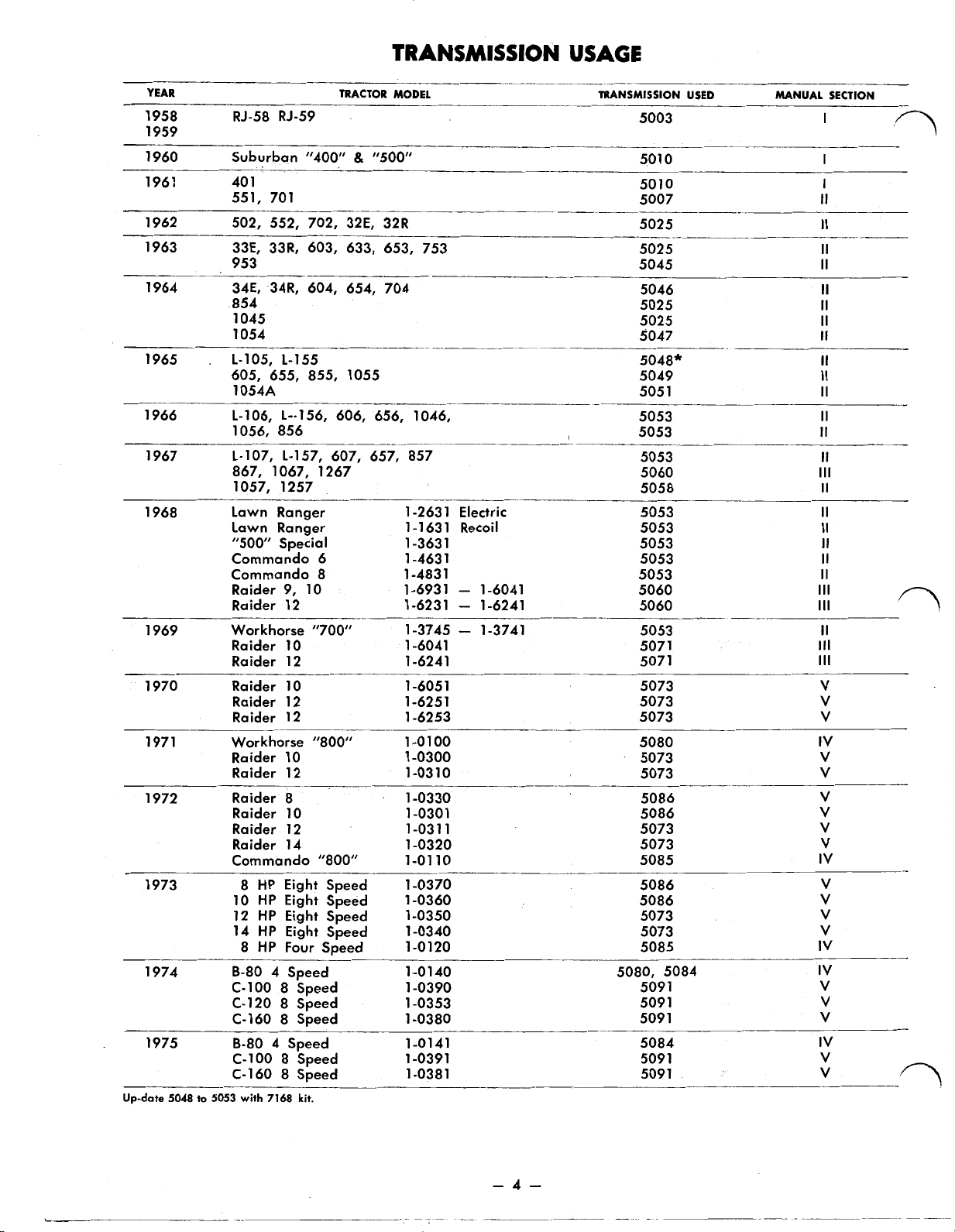
USAGE
YEAR TRACTOR MODEL TRANSMISSION USED
1958
1959
1960 Suburban "400"
1961 40
1962 502, 552, 702, 32E, 32R 5025
1963 33E, 33R, 603, 633, 653, 753 5025
1964 34E, 34R, 604, 654, 704 5046
1965 L-105, L-155 5048*
1966
1967 L-107,
1968 Lawn Ranger 1-2631 Electric 5053
1969 Workhorse "700" 1-3745 1-3741 5053
1970 Raider
1971 Workhorse "800"
1972 Raider 8 1-0330 5086
1973
1974
1975 B-80 4 Speed 1-0141 5084
Up-date
5048
RJ-58 RJ-59
&
"500" 501
1
551, 701
953
854
1045
1054
605, 655, 855, 1055
1054A
L-106, L--156, 606, 656, 1046,
1056, 856
L-157,
867, 1067, 1267 5060
1057, 1257
Lawn Ranger 1-1631 Recoil 5053
"500" Special 1 -363
Commando 6
Commando 8 1-483
Raider 9, 10 1-6931
Raider 12 1-6231 - 1-6241 5060
Raider
Raider 12 1-6241 5071
Raider 12 1-625 1
Raider 12 1-6253
10
10
607, 657, 857
1
-463
1 -604
1
-605 1
1
1
1
-
1-6041 5060
1
1-0100
Raider
Raider 12 1-031
Raider
Raider 12 1-031
Raider 14 1-0320 5073
Commando "800"
10
12
14
8-80 4 Speed 1-0140 5080, 5084
C-1
C-120 8 Speed 1-0353 5091
C-160 8 Speed 1-0380 509
C-100 8 Speed
C-160 8 Speed
to
5053
10
1-0300 5073
0
10
1-0301 5086
1
1-01
10 5085
HP
Eight Speed 1-0370 5086
8
HP
Eight Speed 1-0360 5086
HP
Eight Speed 1-0350 5073
HP
Eight Speed 1-0340 5073
8
HP
Four Speed 1-0120 5085
00
8 Speed 1-0390 5091
1
1 -039
1
-038
1
with
7168
kit.
5003
5010
5007
5045
5025
5025
5047
5049
505
5053
5053
5053
5058
5053
5053
5053
5071
5073
5073
5073
5080
5073
5073
5091
5091
MANUAL SECTION
I
0
I
I
II
II
II
II
II
II
II
II
II
II
1
II
II
II
II
Ill
II
II
II
II
II
II
Ill
Ill
II
Ill
Ill
V
V
V
IV
V
V
V
V
V
V
IV
V
V
V
V
IV
IV
V
V
1
V
IV
V
V
-4-
Page 8
TRANSMISSION USAGE
YEAR TRACTOR
1976 B-60 8-Speed 6
1
977 B-60 8-Speed 7
MODEL
B-80
8-Speed 6
B-80
8-Speed
B-
1
00
8-Speed
B-
1
00
8-Speed
C-
1
20
8-Speed
C-120 8-Speed
C-160 8-Speed
C-
160 8-Speed 61
B-80
8-Speed 71 -08K801
B-100 8-Speed 71-10K801 103907
C-120 8-Speed 71
C-
1
60 8-Speed 71-16K801
VIN
NUMBER TRANSMISSION MANUAL
1
-07K80
1
1
-08K80
1
61 -08K802
6 1 -08K804
61 -08K803
61-10K801,
61
-1
61
-1
61-1OK803
-1
61
61-12K802
61
-1
61
-1
61-16K801,
61 - 16K802
61
-1
-1
1
-07K80
-1
OK802
OK804
2K801,
2K804
2K803
6K804
6K803 103907
2K801 103907
&
&
&
&
1
&
71-16K802
USED SECTION
5091
5091
1
03907
5091
1
03907
5091
1
03907
5091
1
03907
1
03907
1
03907
V
V
V
V
V
V
V
V
V
V
V
V
V
V
8
1
1978 C-81 8-Speed
C-101 8-Speed
C-
1 2 1
8-Speed
C-
1 4 1
8-Speed
C-
1 6 1
8-Speed
C-161 Twin 8-Speed
1
979 C-81 8-Speed 91-08K801
C-101 8-Speed
C-1
1
1
8-Speed 91
C-
1
2 1 8-Speed
C-
141 8-Speed
C-161 8-Speed
C-161 Twin 8-Speed 91-168801
-08K80
81
-1
OK801
-1
2K801
81
81-14K801
81-16K801
-1
68801
81
9 1 -08K802
91
-1
OK801
91-1OK802
-1
18801
-1
2K801
91
-1
2K802
91
91-14K801
91
-
1
4K802
91 -1 6K801
-
168802
91
1
&
&
&
&
&
10391 6
10391 6
10391 6
10391 6
10391 6
10391 6
10391 6
10391 6
10391 6
10391 6
10391 6
10391 6
10391 6
V
V
V
V
V
V
v
V
V
V
V
V
V
Page 9
TRANSMISSION
USAGE
YEAR
1980 C-85 8-Speed
C-105 8-Speed
1
100 Special
C-
C-
C-165 8-Speed
C-175 Twin 8-Speed
E-
1981 C-85 8-Speed
C-
C-
C-145 8-Speed
C-165 8-Speed
C-175 Twin 8-Speed
E-141 8-Speed
GT-2500 8-Speed
1982 C-85 8-Speed
C-
C-125 8-Speed
C-175 Twin 8-Speed
E-141 8-Speed
GT-1142 8-Speed
GTSB-421 8-Speed
SK-486 8-Speed
TRACTOR
1
25 8-Speed
1
45 8-Speed
1
41 8-Speed
105 8-Speed
1
25 8-Speed
1
05
8-Speed
1
642 8-Speed
MODEL
VIN
NUMBER
01-08K801
01
-08K802
01
-1
OK801
-1
18803
01
01
-1
2K801
01
-1
4K801
01
-1
6K801
01
-
1
7K802
01
-1
4E801
0
1
-08K802
-1
OK802
01
01
-1
2K802
01-14K802
01-16K802
01
-
1
7K802
01
-1
4E801
01
-1
18804
01 -08K803
01-10K803
01
-1
2K803
-1
7K803
01
01
-1
4E801
Al-114201
A1
-1
64201
01
-1
1
BHO1
01
-1
6KH01
&
TRANSMISSION MANUAL
USED SECTION
10391
10391
5086
10391
10391
10391
10391
10391 8
10391
10391
10391
10391
10391
10391
10391 8
5086
10391
10391
10391
10391
10391
6
6
6
6
6
6
6
6
6
6
6
6
6
6
6
6
6
V
V
V
V
V
V
V
V
V
V
V
V
V
V
V
V
5086
5086
5086
5086
n
-
4B
-
Page 10
Section
I
5003
-
5010
DESCRIPTION
The 5003 and
tified
by
their removable steel side covers which are
bolted to a one piece cast iron case. The transmissions
are of the sliding gear type. and provide three speeds
forward and one speed in reverse.
All
shafts operate on needle or ball bearings sup-
ported
by
5010
transmissions are readily iden-
the steel side covers.
1st gear
2nd gear
3rd
gear
Reverse
...............
..............
...............
...............
REMOVAL .AND REPLACEMENT
TRANSMISSIONS
The differential
original equipment transmissions, the ring gear
integral part of the differential case. The service replacement, however, consists of a case and gear assembly in which the gear
case.
RATIOS
66.8
to
1
42.4
to
1
24.6
to
1
51.5
to
1
is
of
the spur pinion type. On all
is
bolted to the differential
is
an
Removal:
Remove any mid-mounted or trailing attachment
which might interfere with transmission removal.
Provide-some support under the tractor frame ahead
of the transmission.
Remove the seat, fender and tool box assembly
so
equipped, belt guard, belt, and clutch rod. Discon-
nect the
lift
cable and remove the hitch.
if
Remove three bolts at each transmission side cover
and frame side rail. Move transmission assembly
away from the tractor. Remove the wheels and hubs,
clutch and idler arm assembly, and transmission input pulley.
Drain lubricant and clean case as necessary
fore disassembling.
Installation:
Install clutch and
and input pulley. Install wheels and hubs and move rod. Lay lift cable in place along top
assembly into place on the tractor. Install three bolts
through holes in each transmission side cover and Install fender and tool box assembly
corresponding holes in frame
securely. neath tractor frame.
idler
arm assembly, brake rod, Install drive belt and belt guard. Connect clutch
install hitch and connect lift cable.
side
rails. Tighten nuts equipped, and install seat. Remove support from
of
transmission,
be-
if
so
be-
-5-
Page 11
5003 - 5010
Disassembly:
3-SPEED
TRANSMISSION
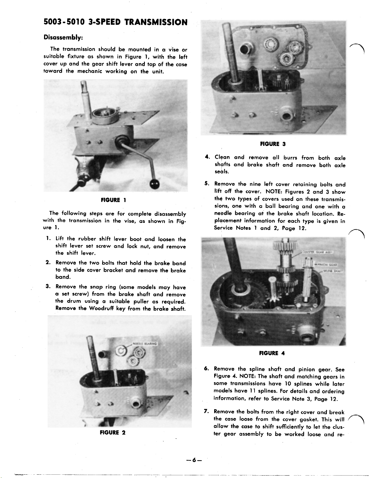
The transmission should
suitable fixture as shown in Figure
cover up and the gear
toward the mechanic working on the unit.
The following steps are for complete disassembly
with the transmission in the vise, as shown in Fig-
1.
ure
shift
FIGURE
be
mounted in a vise or
1,
with the left
lever and top of the case
1
FIGURE
4.
Clean and remove all burrs from both axle
shafts and brake shaft and remove both axle
seals.
5.
Remove the nine left cover retaining bolts and
lift
off
the cover. NOTE: Figures 2 and 3 show
the
two types of covers used on these transmissions, one with a ball bearing and one with a
needle bearing at the brake shaft location. Replacement information for each type
Service Notes
1
and
2,
3
Page
is
12.
given in
1.
Lift the rubber shift lever boot and loosen the
shift lever set screw and lock nut, and remove
the shift lever.
2.
Remove the two bolts that hold the brake band
to the
band.
3.
a set screw) from the brake shaft and remove
the drum using a suitable puller as required.
side
cover bracket and remove the brake
Remove the snap ring (some models may have
Remove the Woodruff key from the brake shaft.
FIGURE
2
FIGURE
6.
Remove the spline shaft and pinion gear. See
Figure
4.
NOTE: The shaft and matching gears in
some transmissions have
models have
information, refer to Service Note
7.
Remove the bolts from the right cover and break
the case loose from the cover gasket.
allow the case to
ter gear assembly to be worked
11
splines. For details and ordering
shift
4
10
splines while later
3,
sufficiently to
Page
let
loose
12.
This
will
the clus-
and re-
Page 12
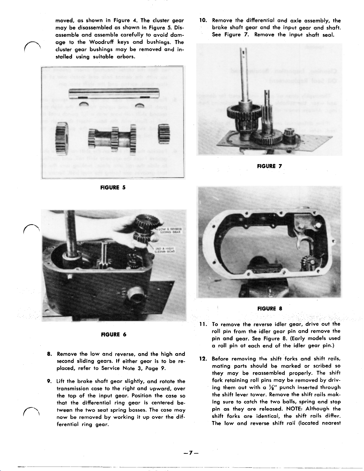
moved, as shown in Figure
may be disassembled as shown in Figure
assemble and assemble carefully to avoid damage to the Woodruff keys and bushings. The
cluster gear bushings may be removed and installed using suitable arbors.
4.
The cluster gear
5.
Dis-
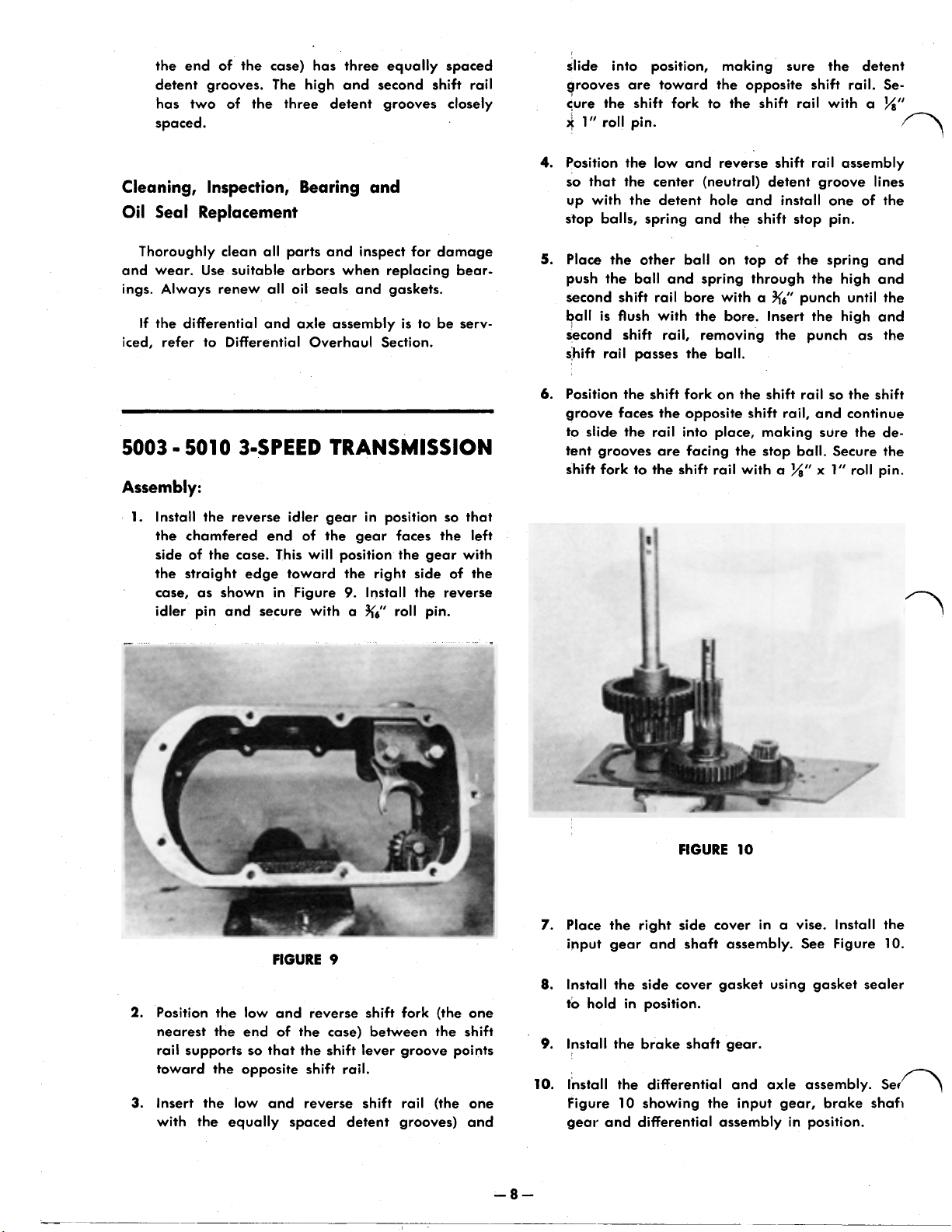
10.
Remove the differential and axle assembly, the
brake shaft gear and the input gear and shaft.
See Figure
7.
Remove the input shaft seal.
FIGURE
FIGURE
8.
Remove the low and reverse, and the high and
second sliding gears.
placed, refer to Service Note
9.
Lift
the brake shaft gear slightly, and rotate the
transmission case to the right and upward, over
the
top of the input gear. Position the case
that the differential ring gear
tween the two seat spring bosses. The case may
now be removed by working it up over the
ferential ring gear.
5
6
If
either gear
3,
Page
is
centered
is
to
9.
be
re-
so
be-
dif-
FIGURE
FIGURE
11.
To remove the reverse idler gear, drive out the
roll pin from the
pin and gear. See Figure
a roll pin at each end of the idler gear pin.)
12.
Before removing the
mating parts should be marked or
they may be reassembled properly. The shift
fork retaining roll pins may
ing them out with a
the
shift
lever tower. Remove the
ing sure to catch the two bails, spring and stop
pin as they are released. NOTE: Although the
shift forks are identical, the shift rails differ.
The low and reverse shift rail (located nearest
idler
7
8
gear pin and remove the
8.
(Early models used
shift
forks and
be
removed by driv-
1/8”
punch inserted through
shift
shift
rails,
scribed
rails mak-
so
Page 13
the end of the case) has three equally spaced
detent grooves.
has two of the three detent grooves closely
spaced.
The
high and second shift rail
Cleaning, Inspection, Bearing and
Oil Seal Replacement
slide into position, making sure the detent
grooves are toward the opposite shift rail. Se-
shift
cure the
1”
1”
roll pin.
4.
Position the low and reverse
so
that the center (neutral) detent groove lines
up with the detent hole and install one of the
stop balls, spring and the shift stop pin.
fork to the shift rail with a
shift
rail assembly
x”
Thoroughly clean all parts and inspect for damage
and wear. Use suitable arbors when replacing bearings. Always renew all oil seals and gaskets.
If
the differential and axle assembly
iced, refer to Differential Overhaul Section.
5003 - 5010 3-SPEED
TRANSMISSION
is
to
be
serv-
Assembly:
1.
Install the reverse idler gear in position
the chamfered end of the gear faces
side
of
the
case.
This
will position the gear with
the straight edge toward the right side of
case, as shown in Figure
idler pin and secure with a
9.
Install the reverse
3/16”
roll pin.
so
the
that
left
the
5.
Place the other ball on top of the spring and
push the ball and spring through the high and
second
ball
second
shift rail
6.
Position the shift fork on the
groove faces the opposite
to slide the rail into place, making sure the
tent grooves are facing the stop ball. Secure the
shift
shift
rail bore with a
is
flush with the bore. Insert the high and
shift
rail, removing
passes
fork to the
the ball.
shift
rail with a
3/16”
punch until
the
punch as
shift
rail
shift
rail, and continue
1/8”
x
so
1”
the
the
the
shift
de-
roll pin.
FIGURE
2.
Position the low and reverse shift fork (the one
nearest the end of the case) between
rail supports
toward the opposite
3.
Insert the low and reverse
with the equally spaced detent grooves) and
so
that the
shift
9
shift
lever groove points
rail.
shift
rail (the one
the
shift
-8-
FIGURE
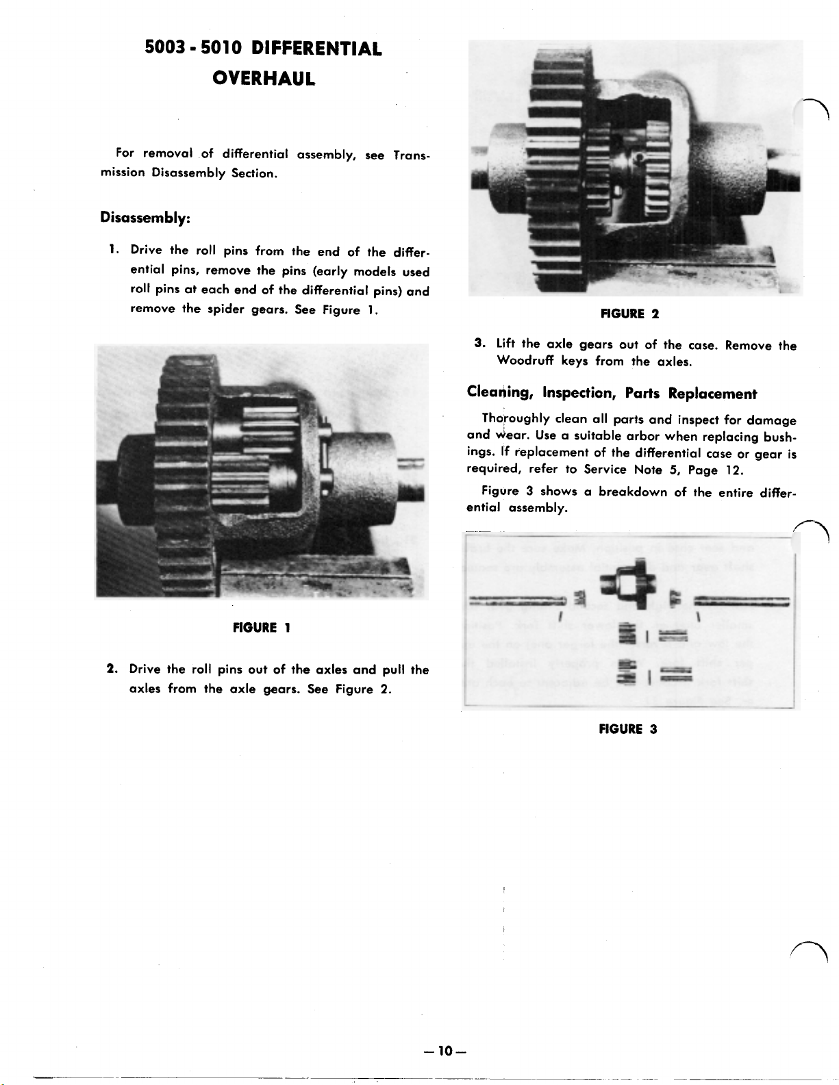
Place the
7.
input gear and shaft assembly.
Install
8.
to
hold in position.
9.
Install the brake shaft gear.
10.
Install the differential and axle assembly.
Figure
gear and differential assembly in position.
right
side cover in a vise. Install the
the
side cover gasket using gasket sealer
10
showing the input gear, brake shaft
10
See
Figure
10.
Page 14
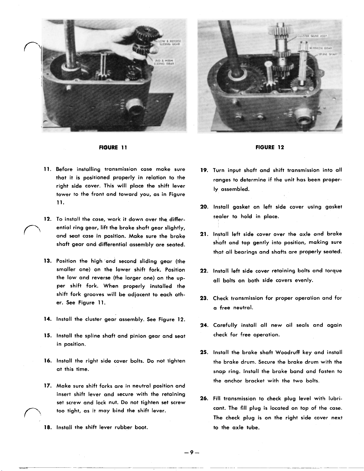
FIGURE 11 FIGURE 12
11.
Before installing transmission case make sure
that it
right side cover.
tower to the front and toward you, as in Figure
is
positioned properly in relation to the
This
will place the shift lever
11.
12.
To
install
the
case, work
ential ring gear,
and seat case in position. Make sure the brake
shaft gear and differential assembly are seated.
13.
Position the high 'and second sliding gear (the
smaller one) on the lower shift fork. Position
the low and reverse (the larger one) on the up-
per shift fork. When properly installed the
shift
fork grooves will
er.
See Figure
14.
Install the cluster gear assembly.
15.
Install the spline shaft and pinion gear and seat
in position.
16.
Install the right side cover bolts.
this
at
17.
Make sure
insert
set screw and lock nut.
too tight, as
18.
Install the shift lever rubber boot.
time.
shift
lift
11.
shift
forks are in neutral position and
lever and secure with the retaining
it
may bind the shift lever.
it
down over the differ-
the brake shaft gear slightly,
be
adjacent to each oth-
See
Do
Do
not tighten set screw
Figure
not tighten
12.
19.
Turn input shaft and shift transmission into all
ranges
ly assembled.
Install gasket on left
20.
sealer to hold in place.
21.
Install left side cover over the axle and brake
shaft and tap gently into position, making sure
that all bearings and shafts are properly seated.
22.
Install left side cover retaining bolts and torque
all bolts on both side covers evenly.
23.
Check
a free neutral.
24.
Carefully install all new
check
25.
Install the brake shaft Woodruff key and install
the brake drum. Secure the brake drum with the
snap ring. Install
the anchor bracket with
26.
Fill
cant. The
The
to
to
determine
transmission for proper operation and for
for free operation.
transmission to check plug level with lubri-
fill
plug
check
plug
the
axle tube.
if
the unit has been proper-
side
cover using gasket
oil
seals and again
the
brake band and fasten to
the
two bolts.
is
located on top of the case.
is
on
the
right side cover next
Page 15
5003
-
5010
DIFFERENTIAL
OVERHAUL
For removal of differential assembly, see Trans-
mission Disassembly Section.
Disassembly:
1.
Drive the roll pins from the end of the
ential pins, remove the pins (early models used
the
roll pins at each end of
remove the spider gears. See Figure
differential pins) and
1.
differ-
FIGURE
3.
lift
the axle gears out of the case. Remove the
Woodruff keys from the axles.
2
FIGURE
2.
Drive the roll pins out of the axles and pull the
axles from the axle gears. See Figure
1
2.
Cleaning, Inspection,
Thoroughly clean
and wear.
ings.
required, refer to Service Note
Figure 3 shows a breakdown of the entire differential assembly.
Use
a
suitable arbor when replacing bush-
If
replacement of the differential case or gear
Parts
all
parts and inspect for damage
Replacement
5,
Page
12.
is
Page 16
5003
-
501
0
DIFFERENTIAL
2.
Place the
Figure
through the spiders and secure with roll pins.
spider
6,
slide the differential pins into position
gears in position, as shown in
FIGURE
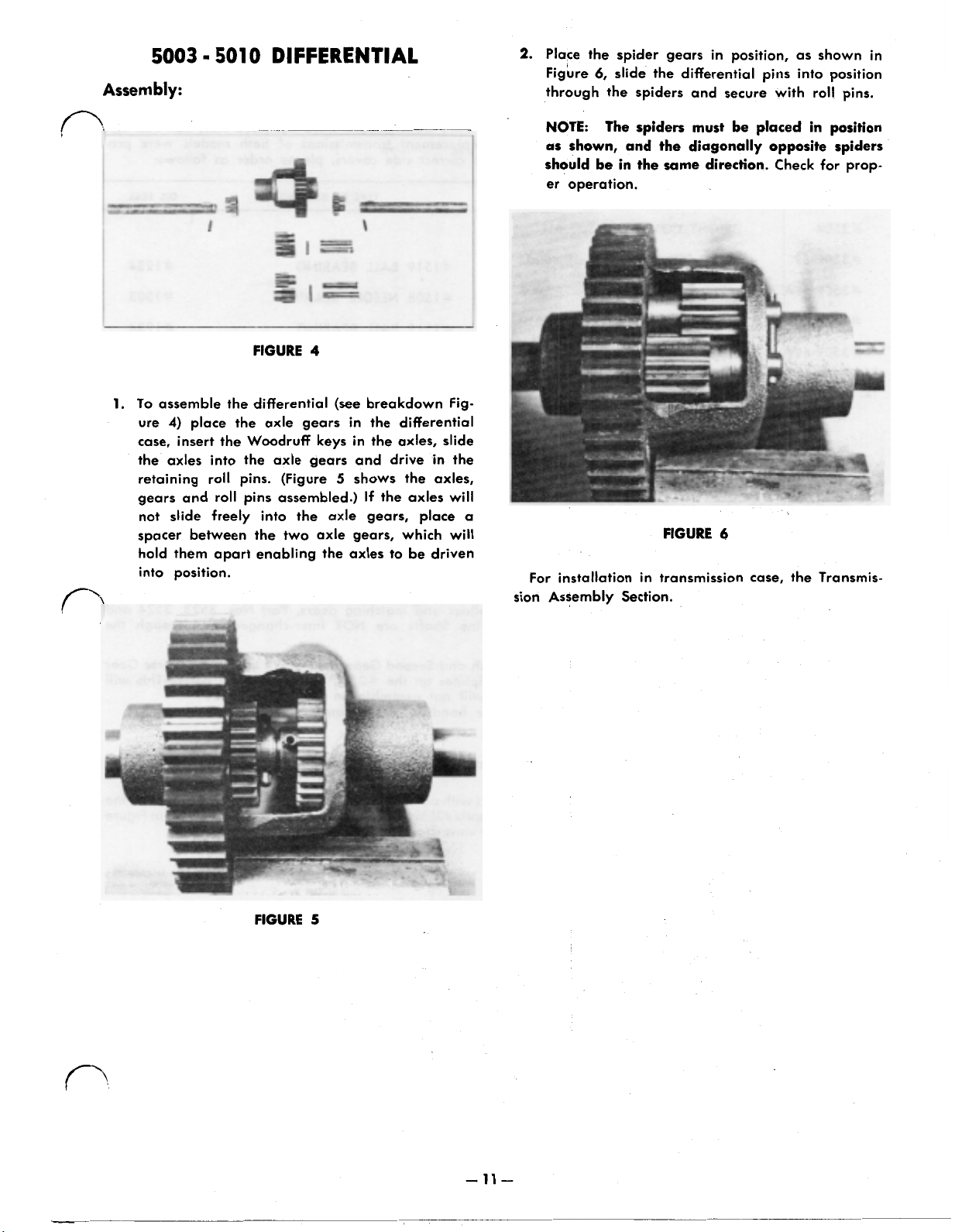
1.
To assemble the differential (see breakdown Figure
4)
place the axle gears in the differential
case, insert the Woodruff keys in the axles,
the axles into the axle gears and drive in the
retaining roll pins. (Figure
gears and roll pins assembled.)
not
slide
freely into the axle gears, place a
spacer between the two axle gears, which will
hold them apart enabling the axles to be driven
into position.
4
5
shows
the
If
the axles will
slide
axles,
NOTE:
as
should be in the same direction.
er operation.
For installation in transmission case, the Transmis-
sion Assembly Section.
The spiders must be placed in position
shown, and the diagonally opposite spiders
Check
for prop-
FIGURE
5
-
11
-
Page 17
5003
1.
TRANSMISSION COVERS
All #5003 production transmissions and the early #5010 transmissions were equipped with ball bearings
on the brake shaft. Late #SO10 transmissions and replacement transmissions of both models were pro-
duced with needle bearings. To insure receiving the correct side covers, please order as follows:
PART
NO.
DESCRIPTION USED
AND
5010
ON
SERVICE
NOTES
TYPE
OF
BEARING
OIL
SEAL
'
#3504 RIGHT COVER
#3509-59
#3509-59A
#3509-60
#
3509-60A
2.
#3559
A.
B.
3.
SPLINE
All tractors and replacement transmissions produced previous to tractor Serial No. 11628, contain Part
NO. 3521 Spline Shafts with 10 straight
3526.
All tractors and replacement transmissions produced after tractor serial number 11628, contain Part No.
3521 Spline Shafts with 11 involute tooth form splines and matching gears, Part Nos. 3523, 3524 and
3526. The matching gears for
part numbers are identical.
It
or the #3526 Splined Pinion Gear, the number of Splines on
eliminate the possibility of receiving gears which will not assemble on the Spline Shaft.
The ordering of the #3521 Spline Shafts should be handled in the same manner.
4.
#3559
BRAKE SHAFTS
Original equipment brake shafts used in ball bearing type transmissions cannot be used with needle
bearing
Presently stocked brake shafts and those used in needle bearing transmissions are interchangeable.
To
install in ball bearing transmissions, use four 1197 Shim Washers between the brake shaft gear
and the left side cover plate.
SHAFT AND MATCHING GEARS
is
suggested that, when ordering the #3523 High and Second Gear, the #3524 Low and Reverse Gear
BRAKE SHAFT
side
LEFT
COVER
LEFT
COVER
LEFT
COVER #5010
LEFT
COVER #5010 #1508 NEEDLE BEARING
covers.
the
ALL
#
5003
#
5003
#
1519 BALL BEARING
#
1508 NEEDLE BEARING
#
1519 BALL BEARING
#
#
#
#
sides
splines and matching gears, Part
two types of Spline Shafts are NOT inter-changeable, although the
the
#3521 Spline Shaft be noted.
Nos.
3523, 3524 and
1234
1303
1234
1303
This
will
The original #3559 brake shaft has been replaced with a new design. The new shaft has more strength and able
to carry more load.
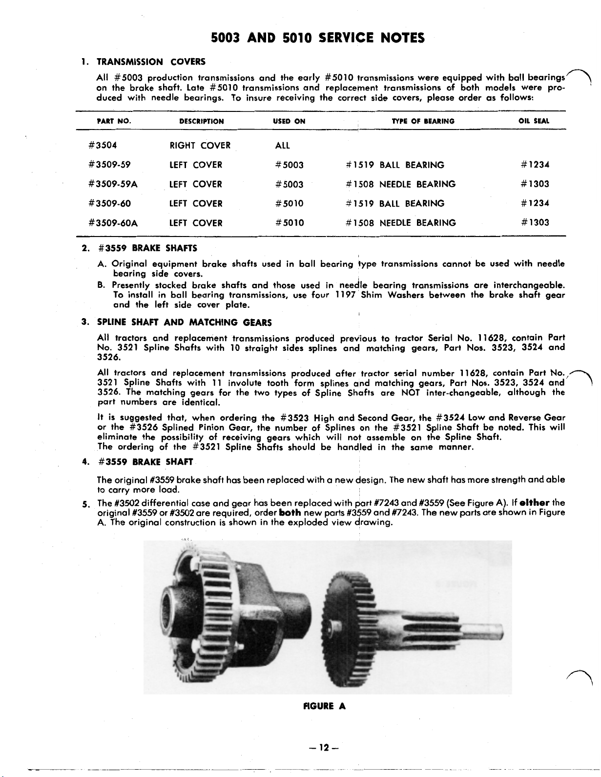
The #3502 differential case and gear has been replaced with part #7243 and #3559 (See Figure A). If
5.
original #3559 or #3502 are required, order
A. The original construction
is
shown in the exploded view drawing.
both
new parts #3559 and #7243. The new parts are shown in Figure
FIGURE
-
A
12 -
either
the
Page 18
Page 19

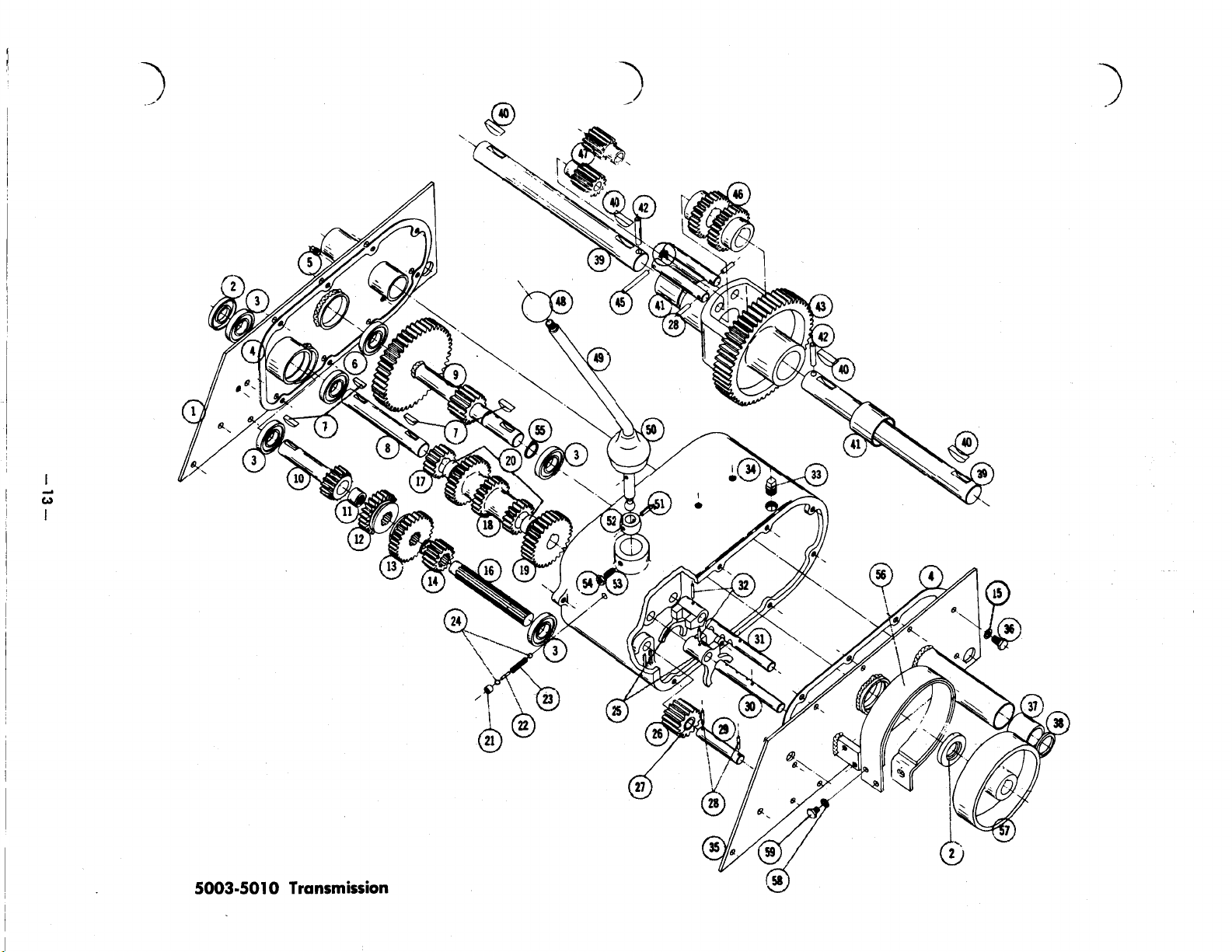
5003 - 5010
TRANSMISSION
**
**
***
* 13
Ref.
No.
1
2
3
4
5
6
7
8
9
10
11
12
14
15
16
17
18
19
20
21
22
23
24
25
26
27
28
29
30
Part
No.
3504
1234
1519
3536
1108
1502
1122
3533
3559
3522
1518
3523
3524
3526
920082-4
3521
3528
3525
3527
1504
1
243
3573
3518
351 7
3503
3520
1516
933 188
3519
3515
When ordering parts always list Part
(Specifications subject
Description
Right Transmission Cover
Seal
Oil
Ball
Bearing
Gasket Transmission
Pipe Plug
Ball
No.
Cluster Shaft
Brake Shaft and Gear
Input Gear
Needle Bearing
Hi
low & Reverse
Splined Pinion
Lockwasher
Spline Shaft
Cluster Shaft Reduction Pinion
Cluster
Cluster Shaft Reduction Gear
Bronze Bearing
Cup Plug
Pin
Spring
Ball
Shift Fork
Reverse Idler
Bearing
Roll Pin
Reverse Idler Pin
Shift
1/8”
Bearing
9
Woodruff
h
Second
Gear
5/16
-
Shift
-
Shift
-
stop
-
3/16
Rail - Front
Key
Gear
Gear
5/16
Dia.
Stop
Stop
Gear
with Bearing
Reverse Idler Gear
x
1
__-
No.
Req'd.
1
2
4
2
1
3
4
1
1
1
1
1
1
1
18
1
1
1
1
2
1
1
1
2
2
1
1
6
1
1
No.
and name of part.
to
change without notice.)
Ref.
No.
31
32
33
34
**
35
36
37
38
39
40
41
42
****
43
44
45
46
47
48
49
50
51
52
53
54
55
56
57
58
59
Pa
rt
No.
3516
933156
1013
3501
3509
90801 6-4
1503
1257
3532
937022
1517
17
9332
3502
3535
933194
3530
1
353
1001
3538
3577
933168
3514
1239
915111-6
9361
25
3543
3540
920081
-4
908002-4
Description
-
Shift Rail
Roll
Pipe Plug
Transmission Housing
left
Transmission Cover
Hex Bolt
Bronze Bearing
Oil
Seal
Axle
Key
-
Bronze Bearing
Roll
Differential Case and Gear
Differential Pins
Roll
Axle
Spider Gear - Differential
Knob
lever
Boot - Shift lever
Roll
Collar - Shift Lever
¼-20
Nut - Hex
Snap Ring
Brake Band with liner
Brake Drum
lockwasher
Hex
Rear
Pin
x
1
5/16-18
x
5/8
Woodruff No.
Pin x
Pin
Gear - Differential
Pin
1½
3/16
x
1¾
-
Shift
5/32
x
13/16
x
3/4
Dog Point Set Screw
¼-20
3/4”
Truarc
1/4”
Dm.
Bolt
¼-20
x
5/8
15
No.
Req’d.
1
2
1
1
1
18
2
2
2
4
2
2
1
4
2
2
1
1
1
1
1
1
1
1
1
1
2
2
*See
Service Note
**See
Service Note
***See
****See
Service
Service
Note
Note
#3
#1
#2 & 4
#5
-
14 -
Page 20

Section
II
5053 - 5058
3-SPEED UNlDRlVE
DESCRIPTION
The 3-speed unidrive transmission
transmission utilizing sliding gears and splined shafts
for easy shifting.
bearings supported by the transmission case. The
transmission case consists of R.H. and L.H. cast iron Model
case halves which are dowelled for alignment and
bolted securely together. gear differential.
The model numbers 5053 and
section stand for the full line
sions produced since
All
shafts operate on needle or ball the spur gear differential.
of
1961.
is
an all-gear Model 5053 covers all standard models
5058
used in
unidrive transmis-
1st
gear
2nd gear
3rd
gear
Reverse
this
...............
..............
...............
................
5025, 5046, 5048, 5049,
5058
5047, 5051, 5059,
66.8
to
42.4
to
24.6
to
51.5
to
and
5053)
equipped with
covers all heavy duty models
and
5058)
incorporating the bevel
1
1
1
1
(5007,
(5045,
REMOVAL AND REPLACEMENT
Removal:
These basic instructions apply to all tractors
equipped with Unidrive transmissions. Deviate from
them as necessary for any particular tractor.
Remove mid-mounted or trailing attachments, or
hitches
moval. Support the tractor frame ahead of the transmission just enough that the rear wheels no longer
carry any weight.
guard, and belt. Disconnect the brake rod or remove
the brake band from the anchor bracket. On most Drain lubricant, remove wheels, and clean transmodels, remove the fender and seat assembly.
which might interfere with transmission re-
remove the R.H. foot
rest,
if
so
equipped,
belt
If
necessary to gain clearance, remove
and instruction plate located just ahead of the shift
lever.
Remove two cap screws that fasten through the
bottom of the tool box into the top of the transmission. Remove four cap screws that go through the
frame butt plate into the front of the transmission.
Lower the front of the transmission, guide the shift
lever down between the frame rails, and roll the
transmission and wheel assembly
mission as necessary before disassembling.
the
free
of the tractor.
dust cover
Installation:
NOTE:
used to facilitate transmission installation. To make lower
the studs, cut the heads off of two
head or carriage bolts. Grind a taper on the un- Install input pulley, axle hubs and wheels. Move
threaded end of each bolt. Screw one stud into one
of the upper holes in the front of the transmission
It
is
recommended that two Pilot studs
3/8"-16
be
case. Put the other one in
the
diagonally opposite
hole.
x
2"
hex
the transmission assembly into place and guide the
shift lever up between the frame rails. Align the pilot
Page 21

studs with the corresponding holes in the frame butt Connect brake linkage. Install dust cover, instruc-
plate and push the transmission firmly in place tion plate, fender and seat assembly, drive belt, belt
against the plate. Install cap screws in the top
the transmission and the open holes in the front, and
tighten them until snug. Remove the pilot studs one
at a time, replacing them with cap screws. Tighten gear oil. Remove support from beneath tractor frame.
all six cap screws securely. Test tractor operation.
of
guard) foot rest, etc.
Fill
the transmission to proper level with
S.A.E.
90
UNlDRlVE TRANSMISSION
Disassembly:
These
instructions apply to all unidrive models un-
less
indicated.
models will
1.
Remove axle hubs and input pulley.
2.
Place
suitable holding fixture, as shown in Figure
A
section applying only to specific
be
so
identified.
the
transmission assembly in a vise or
5053
1.
-
5058
FIGURE
7.
Remove paint and burrs from both axle shafts,
brake shaft, and the input shaft.
2
FIGURE
3.
Place the gear shift lever in neutral and pull
the gear shift lever rubber boot away from the
transmission boss. Loosen the gear shift lever
retaining lock nut and set screw and remove
the gear
4.
Remove the two
and remove the brake band.
5.
Remove the brake drum retaining ring and re-
move the brake drum using a suitable puller
as required.
6.
Remove
retain the right hand and left hand cases.
shift
the
See
six
lever.
(2)
Figure
(6)
1
brake band retaining bolts
2.
3/8’’
x
16
bolts and nuts that
8.
Remove the left hand case, as shown in Figure
FIGURE
3
3.
Page 22

9.
Lift out the axle and differential assembly. Figure
4.
Note:
If
only the differential
hauled the transmission need not be further
assembled. See Differential Overhaul Section.
10.
Shift the 2nd and high
into the 2nd speed position. See Figure
shift
is
fork assembly up
LOW
to be over-
dis-
4.
&
REVERSE
SHIFT
(NEUTRAL POSITION)
FORK
FIGURE 4
The following steps
unidrive models except
5058
and
5059
follow steps
11.
Remove the splined pinion shaft and gear. At
the same time the cluster gear assembly may be
removed. See Figure
11
5058
5.
through
and
1A
17
5059.
through
apply
For models
7A.
to
all
FIGURE
FIGURE
14.
Place the shift forks in neutral and remove first
the low and reverse shift rail and fork assembly,
then the 2nd and
bly, being careful not to lose the two stop balls,
spring and stop pin
ure
8.
high
6
7
shift rail and fork assem-
as
they are released.
Fig-
FIGURE
12.
Remove the brake shaft gear assembly and the
reverse idler gear. See Figure
Remove the 2nd and high sliding gear and the
13.
low and reverse sliding gear, as shown in Figure
5
6.
7. FIGURE
-
17 -
8
Page 23

15.
Remove the reverse idler shaft and the input
shaft and gear. See Figure
idler
shaft may sometimes stick in the left hand
case.
9.
Note: The reverse
FIGURE 9
16.
If
it
is
desired to replace
may easily
able arbors. When replacing bearings they should
be
pressed in
inside of the case, as shown in Figure
be
removed and installed with suit-
so
that they are flush with the
the
case bearings they
IDLER
10.
17.
The cluster gear may be disassembled, as shown
in Figure
fully to avoid damage to the woodruff keys and
bushings. The cluster gear bushings may be
removed and installed using suitable arbors.
The following steps
drive models
1A.
Remove the cluster gear assembly, the brake
shaft assembly, and the reverse idler gear and
shaft.
11.
Disassemble and assemble care-
1A
5058
and
through
5059
7A
only.
apply
to
Uni-
FIGURE 10
FIGURE 12
2A.
Remove the splined pinion gear from the input
shaft.
3A.
Place the
low and reverse shift rail and fork assembly
(the one nearest the end of the case) together
with the low and reverse sliding gear making
sure
removed. See Figure 12.
4A.
Remove the 2nd and high shift rail and fork
assembly together with the 2nd and high sliding
gear.
5A.
Remove the remaining stop ball, spring and stop
pin.
6A.
Remove the input shaft and gear assembly.
7A.
Refer to step
shift
fork in neutral and remove the
to
catch the stop ball as the shift rail
17
if
cluster
is
to
be
overhauled.
Cleaning, Inspection, Bearing and
Oil
Seal Replacement
is
FIGURE 11
Thoroughly clean all parts and inspect for damage
Use
and wear.
ings. Always renew all oil seals and gaskets.
-
18
-
suitable arbors when replacing bear-
Page 24

UNlDRlVE
TRANSMISSION
5053
-
5058
Assembly:
Place
the
right hand case in a vise or other suit-
able fixture for assembly, as shown in Figure
13.
FIGURE
The following steps apply to all unidrive models
except
5058
and
5059.
1B
through
1.
Install the input shaft and gear, and reverse
idler
17B.
shaft, as shown in Figure
For
these models,
13
follow
14.
steps
FIGURE 15
Install the 2nd stop ball and using a punch
4.
push the ball in against the spring. Move the
'2nd
&
high
shift
rail into the neutral position
and continue to push on the punch until the ball
is
flush with the
insert the low and reverse shift rail and fork
'assembly, removing the punch, as the shift rail
passes the ball.
and
16.
shift
rail bore. At the same time
See
Detent Drawing. Figure
15
FIGURE 14
2.
Install the 2nd and high shift rail and fork as-
(the
sembly
grooves.) See Figure
3.
Install one stop ball, spring and stop pin. Refer
to detent drawing and Figure
one with the unequally spaced detent
16.
15.
-
19 -
FIGURE
16
Page 25

5.
Shift
the 2nd and high
speed position and install the 2nd and high
sliding gear, and the low and reverse sliding
gear in position on their respective forks, Figure
17.
Note that the shift fork grooves
gears face each other, and that
is
the two gears
goes on the bottom,
the 2nd and high gears which
shift
fork into the 2nd
of
the
the sliding
smaller of
FIGURE 19
FIGURE
6.
Install the reverse idler and the brake shaft, as
shown in Figure
end on the reverse idler goes down.
7.
Install the splined shaft and gear through the
two splined sliding gears seating the bottom end
of the shaft into the input gear bearing.
Figure
fully seating it in its bearing and meshing it
with its related gears.
8.
Install the differential and axle assembly, as
shown in Figure
nuts are up toward the
19.
18,
Install the cluster gear assembly care-
17
making sure that the flanged
20,
making sure that four
L.
H.
case.
See
(4)
FIGURE 20
9.
Place shift forks in neutral position and check
for a free neutral and proper operation in all
gears.
10.
Install a new case gasket holding it in place
with gasket sealer and install the
11.
Install the six
tighten all bolts evenly to avoid distortion.
12.
Install the shift lever assembly and retain with
the set screw and lock nut. Install gear shift
lever rubber boot.
(6)
3/8''
x
16
left
bolts and nuts and
hand case.
FIGURE
18
-
20 -
13.
Check
again for a free neutral and operation in
all gears.
14.
Install the brake shaft Woodruff key and install
the brake drum. Install the brake drum retaining
snap ring.
15.
Install the brake band and secure with the two
retaining bolts.
Page 26

Assembly
of
5058
Series With
Bevel Gear Differential
18. Install the input shaft and gear assembly.
the
2B. Install
sembly (the one with the unequally spaced detent
grooves) together with the 2nd and high sliding
gear (the smaller of
sliding gear fits down over the input shaft with
the shift fork groove up.
3B.
Install one stop ball, spring and stop pin.
drawing Figure
4B.
InstaII the 2nd stop ball and using a punch
push the ball in against the spring. Move the
2nd
&
continue to push on the punch until the ball
flush with the shift rail bore. At the same time
insert the low and reverse shift rail and fork assembly together with the low and reverse sliding
gear, removing the punch as the shift rail passes
the
ball.
The low and reverse gear
input shaft with the shift fork groove down.
Figure 21.
2nd and high shift rail and fork as-
the
two sliding gears).
See
Figure 21.
15.
high shift rail into the neutral position and
(See
detent drawing Figure 15.) Note:
fits
down over the
The
See
is
See
12B. Install a new case gasket holding
gasket sealer and install the left hand case.
13B.
Install the six (6) x 16 bolts and nuts and
tighten all bolts evenly to avoid distortion.
14B. Install the shift lever assembly and retain with
set
the
rubber boot.
15B. Check again for a free neutral and operation
in all ranges.
16B. Install the brake shaft Woodruff key and install
the
snap ring.
17B. Install the brake band and secure with the two
retaining bolts.
screw and lock nut. Install gear shift lever
brake drum. Install
the
brake drum retaining
it
in place with
DIFFERENTIAL OVERHAUL
STANDARD DIFFERENTIAL
Disassembly:
1. Remove
the
four
(4)
retaining bolts and nuts.
2. lift
3.
4.
5.
FIGURE
5B. Install the splined pinion shaft gear down over
the input shaft gear and through the two sliding
gears.
6B.
Shift the 2nd and high shift rail and fork assem-
bly in to 2nd speed position.
7B. Install the reverse idler gear shaft and gear
assembly making sure that
gear goes down.
8B.
Install the brake shaft gear.
98.
Install the cluster gear assembly.
the
10B. Install
the differential bolt heads down. This will place
the left hand differential case with the threaded 7.
bolt holes up. driving out the roll pins.
11B. Place shift forks in neutral position. Check for Figure 2
a
free neutral and proper operation in all ranges. standard differential assembly.
differential and axle assembly with remaining axle shaft and gear from the case.
21
the
shoulder of the
6.
off
the
differential side case together with
the axle shaft and gear.
Remove the axle shaft and gear from the case.
Remove the differential bull gear.
Note position of the four
pinions are installed in opposite directions, which
make the position of the diagonally opposite
pinions the same.
Remove the pinions and shafts and remove the
The
axle shaft gears may easily be removed by
is
an exploded view of the complete
See
FIGURE
(4)
Figure
1
pinions. Adjacent
1.
Page 27

FIGURE
2
STANDARD DIFFERENTIAL
Assembly:
1.
If
the axle gears were removed install them on
the axles and install the retaining
Install one of the axle and gear assemblies in
2.
the differential case and install the four
pinion shafts.
Install two
3.
onally opposite each other, and install the other
two
(2)
opposite each other. See Figure
4.
Install the differential bull gear.
5.
Install the remaining axle and gear assembly in
the remaining differential case.
6.
Position the axle and gear, and differential case
over the pinion shafts, mesh the gears and seat
the case against the ring gear.
7.
Center the bull gear and install the four
retaining bolts and nuts. Tighten securely and
evenly to avoid distortion.
(2)
pinions with their teeth
pinions with their teeth down diagonally
roll
1.
BEVEL GEAR DIFFERENTIAL
Disassembly:
Install differential assembly in a vise, the case
1.
with the threaded holes should be down. Remove
the four
one of the axle shafts, gear, thrust washer and
differential case half as an assembly. See Figure
3.
2.
Remove the bull gear, differential pinion shaft,
differential gears and differential blocks as an
assembly.
Slide the differential blocks and gears toward
3.
the center and remove the assembly from the
bull gear. The differential blocks and gears may
now be removed from the shaft.
The axle shafts, gears and thrust washers may
4.
now be removed from the differential case.
5.
The
shafts by removing the roll pins.
of the parts
(4)
bolts and lock washers and remove
axle gears may be removed from the axle
is
shown in Figure
A
break down
4.
up
pins.
diag-
(4)
(4)
FIGURE
FIGURE
3
4
BEVEL GEAR DIFFERENTIAL
Assembly:
1.
If
the axle gears have been removed from the
axles install the gears and retain with the
pins.
2.
Install a thrust washer on each axle next to the
gear.
3.
Install the short axle, gear and thrust washer
assembly into the. threaded left hand differential
case.
4.
Install differential shaft, gears and blocks as an
assembly into the bull gear and push the gears
and blocks outward, seating the blocks into
position in the bull gear.
Install the bull gear, differential shaft, gears and
blocks as an assembly onto the differential case
seating the differential block and bull gear. See
Figure
5.
Install the right hand (long) axle gear, and
thrust washer assembly into the right hand
di
Install the right hand case and axle assembly
onto the bull gear and center over the differential blocks. Secure with the
washers. Tighten evenly making sure the assem-
blies
3.
differential case.
4-3/8"
seat properly.
roll
bolts and
Page 28

- 23
-
Page 29

Item
No.
1
Part
No.
3900
Description
Care R.H.
5053
When ordering ports always
TRANSMISSION
(Specifications subject
~-
No.
Req'd.
1
PARTS
list
Part No. and name of part.
to
change without notice.)
Item
No.
32
Part
No.
933 156
LIST
Description
Roll Pin x
1
No.
Req'd.
2
~-
2
3
4
5
6
7
8
9
10
11
12
13
14
15
16
17
18
19
20
21
22
23
24
25
26
27
28
29
30
31
1533
1528
1508
1532
1529
1303
1232
3915
3901
1530
1531
3905
3906
4235
3909
908
1
46
1316
3904
3908
93321 7
3522
1518
3523
3907
3524
3526
9361 25
5615
5616
3503
Bearing
-
Ball
1½
-
Bearing
Bearing
Bearing
Bearing
Seal
Seal
Pin
Case
Bearing - Needle
Bearing
Case - Differential
Gear
Gear
Shaft
Bolt
Nut Huglock
Axle - Rear
Gear
Roll Pin x
Gear
Bearing - Needle
Gear Hi
Shaft Spline
Gear
Gear
Snap Ring
Rail
Rail
Fork
Needle
-
Needle I.D.
-
Needle
-
Needle ¾ I.D.
-
Oil ¾ Shaft
-
Oil
1"
-
Dowel
L.H.
-
Needle
-
Differential Bull
-
Differential Pinion
Hex
5/16-18 x 3¼
5/16-18
-
Axle
-
Input
&
2nd
-
low
&
-
Pinion - Splined
¾
Truarc
-
Front Shift
-
Rear Shift
-
Shift
Shaft
1½
Reverse
I.D.
1"
1"
5/8
5/8
I.D.
I.D.
I.D.
I.D.
2
2
2
1
1
1
3
2
1
1
1
2
1
4
5
4
4
2
2
2
1
1
i
1
1
1
1
1
2
33
34
35
36
37
38
39
40
41
42
43
44
45
46
47
48
49
50
51
52
53
54
55
56
*57
'58
'59
'60
*61
'Not inc
351 7
351 8
561 4
3525
1504
3528
3527
3910
9370
1
4
4204
1516
3903
3902
937022
1
9361 3
7376
908062-4
92008 1-4
943460
943420
391 2
908043-4
908038-4
915113-6
5632
3577
1239
9151
11-6
1001
led in No.
5053
Ball
-
Shift
Stop
Spring
-
Shift
Stop
Pin
-
Shift
Stop
Gear
-
Cluster
Bearing
-
Bronze ¾ I.D.
-
-
-
#9
-
-
-
#
3/8
Nut Hex
Assembly.
Reduction Pinion
Reduction
Cluster Gear
Woodruff
Reverse Idler
-
Bronze ½ I.D.
Brake Shaft
Brake
15
Woodruff
1"
Shaft
¼-20
¼
Dia.
Pipe
3/8-16 x 3½
3/8-16 x 2
3/8-16
Nylok
Shift
Stick
¼-20
Nylok
Gear
Gear
Shaft
Key
Gear
Bushing
Gear
Drum
Key
Snap Ring
Ass'y. Brake Band
Bolt Hex
Lockwasher
Plug Pipe
Plug
Gasket
Bolt Hex
Bolt Hex
Nut Hex
Ass'y.
Boot - Shift Stick
Set Screw Dog Point
Knob
2
1
1
1
1
&
lining
x
1
1
5
6
1
1
¼-20
x
1
1
- 24
-
Page 30

- 25
-
Page 31

Item
No.
I___
Par)
No.
Description
5058
When ordering parts always
TRANSMISSION PARTS
(Specifications subject to change without notice.)
No.
Req’d.
list
Port No. and name of part.
Item
No.
Par)
No.
LIST
Description
No.
Req’d.
4
5
7
9
10
11
12
13
14
15
16
17
1
2
3
6
8
6940
1533
1532
1508
1526
1529
1303
1213
3915
694
1530
1531
1232
2822
6446
2821
2820
Case R.H.
Ball
Bearing
Bearing
Bearing - Needle
Bearing
Bearing
Seal - Oil ¾ Shaft
Seal
-
Pin - Dowel
1
Case L.H.
Bearing
Bearing
Seal
-
Case - Differential R.H.
Case
Gear
Gear - Axle
1½
I.D.
-
Needle
-
Needle
-
Needle
Oil
1-1/8
Shaft
-
Needle
-
Needle
Oil
1”
Shaft - Brake
-
Differential L.H.
-
Differential - Bull
1”
I.D.
¾”
I.D.
1-1/8”
I.D.
¾”
I.D.
1”
I.D.
5/8”
I.D.
1
2
1
1
2
2
1
2
2
1
1
1
1
1
1
1
2
33
34
35
36
37
38
39
40
41
42
43
44
45
46
47
48
49
5615
5616
3503
933156
3517
3528
5614
3525
1504
3528
3527
3910
937014
4204
1516
3909
41
66
Rail
-
Front
Shift
Rail - Rear
Fork - Shift
Roll Pin x
Ball
Spring
-
Pin
Gear
Bearing - Bronze ¾ I.D.
Gear
Gear
Shaft - Cluster Gear
Key
Gear
Bushing
Shaft
Gear - Brake Shaft
-
Shift Stop
-
Shift
Shift
Stop
-
Cluster
-
Reduction Pinion
-
Reduction
#9
Woodruff
-
Reverse Idler
-
Bronze I.D.
Shift
1
Stop
1
1
2
2
2
1
1
1
2
1
2
1
1
1
18
19
20
21
22
23
24
25
26
27
28
29
30
31
32
2819
2828
2826
2827
6450
6451
9332 17
908043-4
1
56-4
920
5176
1518
51 73
5174
51 75
3
1
9361
Gear
-
Differential Pinion
Washer
-
Thrust
Block - Differential
Shaft - Differential Pinion
Axle
-
Rear
-
R.H.
Axle
-
Rear - L.H.
Roll Pin
Bolt
Washer-Internal Shakeproof
Gear
Bearing
Gear - Hi & 2nd
Gear
Snap Ring
¼
x
1½
-
Hex
3/8-16
x
3½
-
Input
-
Needle
5/8
I.D.
-
Low & Reverse
Gear - Pinion - Splined
-
1”
Shaft
3/8
Dia.
2
2
2
1
1
1
2
5
4
1
2
1
1
1
1
50
51
52
53
54
55
56
57
58
59
*60
*61
‘62
*63
‘64
*Not included in
3902
937022
4437
908002-4
920081 -4
943460
943420
3912
908038-4
915113-6
5632
1239
9151 11-6
3577
1001
Drum
Key
Ass’y. Broke Band
Bolt
Lockwasher
Plug
Plug
Gasket
Bolt
Nut - Hex
Ass’y. Shift Stick
Set Screw Dog Point
Nut - Hex
Boot
Knob
5058
Assembly.
-
#15
-
-
3/8
-
Brake
Woodruff
Hex
Pipe
Hex
¼-20
x
¼
Dia.
Pipe
3/8-16 x 2
3/8-16
Nylok
¼-20
Nylok
&
Lining
5/8
¼-20
1
2
2
1
1
1
5
6
1
x
¾
1
1
1
- 26 -
Page 32

Section
III
5060
6-SPEED
TRANSMISSION
DESCRIPTION
The 6-speed transmission
sion utilizing sliding gears and splined shafts for easy lection. Low range provides an additional 4 to
shifting.
supported
R.H. and
alignment and bolted securely together.
All
shafts operate on needle or ball bearings duction in each of the 3 speeds forward and also re-
by
the transmission case, which consists
L.H.
cast iron case halves, dowelled for
is
an all-gear transmis- The transmission features high and low range se-
of
verse.
RATIOS
High
Gear
1st gear
2nd gear
3rd
gear
Reverse
The 6-speed transmission also incorporates a spur ditions in which normal differential action would
gear type of limited slip differential.
feature provides increased traction under those con-
The
limited slip transfer power to the wheel with least traction.
Range
66.8 to
42.4 to
24.6 to
51.5
to
low
Range
1
1
1
1
267.2 to
169.6 to
98.4 to
206.0 to
1
1
1
1
REMOVAL AND REPLACEMENT
1
re-
Removal:
These basic instructions apply to all tractors
equipped with 6-speed transmissions. Deviate from
them as necessary for any particular tractor.
Remove mid-mounted or trailing attachments, or
hitches which might interfere with transmission removal. Support the tractor frame ahead of the trans-
mission just enough that the rear wheels no longer
carry any weight.
Remove
guard and
the brake band from the anchor bracket. On most
the
R.H.
foot rest,
belt.
Disconnect the brake rod or remove
if
so
equipped,
belt
Installation:
NOTE: It
used to facilitate transmission installation. To make
the studs, cut
head
or
threaded end of each bolt. Screw the studs into diagonally opposite upper and lower tapped holes in the
front of the transmission case.
Install input pulley, axle hubs and wheels. Move
the transmission assembly into place and guide the
shift
levers up between
pilot studs with the corresponding holes in the frame
butt plate and push the transmission firmly against
is
recommended that two pilot studs
the
heads off of two 3/8"-16 x
carriage bolts. Grind a taper on the un-
the
frame rails. Align the
2"
be
hex
models, remove the fender and seat assembly, the
dust cover and instruction plate located just ahead of
the shift levers.
Remove the cap screws that fasten through the
bottom of the tool box into the top of the transmission. Remove four cap screws that go through
frame butt plate into the front of the transmission.
lower
levers down between the frame rails, and roll
transmission and wheel assembly free of the tractor.
Drain lubricant, remove wheels, and clean
mission as necessary before disassembling.
the plate. Install cap screws in the top of the transmission and the open holes at the front and tighten
them until snug.
them with cap screws. Tighten all six cap screws
curely. Connect brake linkage. Install dust cover, instruction plate, fender and seat assembly, drive belt,
belt guard, foot rest,
gear oil. Remove support from beneath tractor frame.
Test tractor operation.
the
front of the transmission, guide the shift
Remove the pilot studs one at a time, replacing
etc.
Fill
the transmission to proper level with
the
trans-
S.A.E.
the
the
se-
90
Page 33

5060 6-SPEED
TRANSMISSION
Disassembly:
1.
Remove axle hubs and input pulley.
2.
Place the transmission assembly in a vise or
suitable holding fixture, as shown in Figure
(shown with levers, brake band, brake drum,
hubs, and input pulley removed).
6.
Remove the brake drum retaining ring and
remove the brake drum using a suitable puller
as required.
7.
Remove paint and burrs from both axle shafts,
brake shaft and the inut shaft.
8.
Remove the six
1
retain the right hand and
9.
Remove
intact, as shown in Figure 2.
10.
lift out the axle and differential assembly. Note:
If
transmission section need not be further
assembled. Refer to Differential Overhaul Section.
11.
Shift the 2nd and high
into the 2nd speed position.
the
only the differential
(6)
3/8”
x
16
bolts and nuts that
left
hand cases.
left hand case leaving all gears
is
to
be
overhauled, the
shift
fork assembly up
See
Figure
dis-
3.
I
FIGURE 1
3.
Place the
lever rubber boot from the transmission boss.
loosen the shift lever retaining lock nut and set
screw and remove the
4.
Remove the roll pin and remove the high-low
range lever.
5.
Remove the two (2) brake band retaining bolts
and remove the brake band.
shift
lever in neutral and pull the
shift
lever.
shift
FIGURE
12.
Remove the cluster gear assembly, the brake
shaft assembly and the reverse idler gear and
shaft.
13.
Remove the splined pinion gear from the input
shaft.
14.
With a screw driver or other suitable tool remove
the plug from the detent passage, as shown in
Figure
4.
3
FIGURE
2
FIGURE 4
Page 34

15.
Place
the
shift
forks in neutral and remove the
low and reverse shift rail and fork assembly (the
one nearest the end of the case) together with
the low and reverse sliding gear, making sure
to catch the stop ball and other detent parts
as the shift rail
16.
Remove the 2nd and high shift rail and fork
assembly together with the 2nd and high sliding
gears.
17.
Remove the remaining detent parts-ball, spring
and stop pin from the detent passage.
18.
Remove
input shaft. Figure
the
is
removed.
gear and spline assembly from the
5.
23.
Remove the detent bolt from the
careful to catch the stop ball and spring.
24.
Remove the reduction gear shaft (Figure
driving it out toward the inside
remove the reduction gear.
25.
Remove the high-low range shift lever and shaft
assembly from the inside of the case.
shift
of
the case, and
fork being
7)
by
FIGURE
19.
Remove the input shaft. Figure
20.
Remove the sliding gear from the high-low
shift
fork assembly. Figure
the
input shaft to case thrust washer.
21.
range
Remove
5
5.
6.
FIGURE
7
Needle Bearing Replacement:
If
needle bearings are to be replaced they should
be removed and installed with suitable arbors.
Cluster Gear:
The, cluster gear may
in Figure
avoid damage to the Woodruff keys and bushings.
The cluster gear bushings may
stalled using suitable arbors.
8.
Disassemble and assemble carefully to
be
disassembled as shown
be
removed and in-
22.
Remove
fork assembly. Figure
FIGURE 6
the
high-low range detent bolt and
6.
shift
FIGURE 8
Cleaning, Inspection, Bearing and
Oil Seal Replacement
Thoroughly clean all parts and inspect for damage
and wear. Use suitable arbors when replacing bearings. Always renew all oil seals and gaskets.
Page 35

5060
6-SPEED
TRANSMISSION
Assembly:
1.
install
in the hole of the right case below the shift rail
supports.
the
high-low range shift lever (Figure
9)
FIGURE
2.
Position the reduction gear assembly in place
with the large gear down and insert the reduc-
tion gear shaft, driving it in place from the
inside of the case, as shown in Figure
3.
Assemble the high and low range shift fork
assembly (Figure
ball in the detent hole. Using a
on the ball, compressing
time insert
punch as the bolt
10)
the
detent bolt, withdrawing the
9
9.
by inserting the spring and
3/16"
punch, press
the
slides
spring.
in place.
At
the same
FIGURE
6.
lift 'up on the reduction gear and
shaft thrust washer into position. Figure
7.
Install the sliding gear into the high-low range
fork with the groove down. Figure
FIGURE
8.
Install
the high-low range sliding gear and thrust
washer. Figure
9.
Install the gear and spline assembly over the
input shaft, sliding the spline down through
the sliding gear. Figure
the
input shaft, sliding it down through
13.
11
slide
12.
12
13.
.the input
12.
FIGURE
4.
Position the detent bolt and
the slot of the high and low range shift lever
engages the
the
bolt in place until
the shoulder. Torque the detent bolt to
ft.
Ibs.
5.
Using a punch to move the high-low range
shift
lever, check the operation of the detent and
fork assembly.
shift
10
fork (Figure
it
seats securely against
shift
11)
fork
and thread
so
12-17
that
30
-
FIGURE
13
Page 36

10.
Install the 2nd and high
sembly (the one with the unequally spaced detent
grooves) together with the 2nd and high sliding
gear (the smaller of the two sliding gears).
sliding gear tits down over the input shaft with
the
shift
fork groove up.
11.
Install one of the stop balls, stop spring and
stop pin into the detent passage.
shift
rail and fork as-
The
14.
Shift
the 2nd and high
bly into 2nd
15.
Install the reverse
sembly making sure
goes down. Figure
speed
shift
rail and fork assem-
position.
idler
gear shaft and gear as-
the
shoulder of the gear
16.
FIGURE
12.
Install the 2nd stop ball and using a punch,
push the ball in against
installed shift rail into the neutral position and
continue to push on the punch (Figure
is
the ball
same time insert the low and reverse shift rail
and fork assembly together with the low and
reverse sliding gear, (Figure
punch as the shift rail passes the ball. See
tent drawing Figure
verse gear fits down over the input shaft with
the shift fork groove down.
flush with the shift rail bore. At the
14
the
spring. Move the
15)
removing the
17.
Note: The low and re-
14)
until
de-
FIGURE
16
FIGURE 15
Install the splined pinion gear.
13.
- 31
-
16.
Install
FIGURE 17
the
brake shaft gear.
Page 37

FIGURE
17.
Install the cluster gear assembly. See Figure
18.
Install
..--the
down
19.
Recheck
proper operation in all gears in both ranges.
Place the
20.
Install a new case gasket holding
with gasket sealer and install
21.
Install the
tighten all bolts evenly to avoid distortion.
22.
Install
the
lever rubber boot.
the
differential and axle assembly with
long end cap and
into the right hand case. Figure
for proper assembly, a free neutral and
shift
forks in neutral position.
six
(6)
the
shift lever assembly and retain with
set
screw and lock nut. Install gear shift
3/8”
18
the
retaining bolt nuts
the
left
x
16
bolts and nuts and
19.
it
in place
hand case.
18.
FIGURE
23.
Install the high-low range selector lever and
retain with the
24.
Recheck for a free neutral and proper operation
in all gears and ranges.
25.
Install a new plug to seal the detent passage
and drive it in flush with the case.
26.
Install the brake shaft Woodruff key and install
the brake drum. Install the brake drum retaining
snap ring.
27.
Install the brake band and secure with the two
retaining bolts.
3/16”
19
roll pin.
LIMITED
SLIP
DIFFERENTIAL
Disassembly:
1.
Remove the five
that retain the end caps to the differential ring
gear. Note that the nuts are on the right hand side
next to the right hand end cap. Note also that the
right hand end cap and right hand axle are longer
than the left hand end cap and left hand axle.
(5)
bolts, nuts and flat washers
RIGHT
HAND
LONG END
FIGURE
1
CAP
2.
Remove the axles and end caps by pulling the ax-
les in and out to free the end caps from the roll
Caution,
pins.
end caps.
do not pry under the edge of the
I
FIGURE 2
3.
Remove the ten
cylindrical spring from the differential bodies.
4.
Press the two
ferential ring gear.
The right and left differential bodies are iden-
tical with roll pins located next to two
holes. Figure
(10)
differential pinions and the
(2)
differential bodies from the dif-
4.
(2)
bolt
Page 38

The matching roll pin holes in the left hand
end cap are also located next to the bolt holes, each axle.
but in the right hand end cap they are between
bolt holes as shown in Figure
6.
5.
Remove the end caps and thrust washers from
6.
The
axle gears may
the retaining snap rings.
be
removed after removing
FIGURE
3
FIGURE
to each other. Note, that
and axle
end cap and axle.
LIMITED
5
shows the differential parts in relation
the
is
noticeably longer than the left hand
SLIP
DIFFERENTIAL
right hand end cap
Assembly:
1.
Install the axle gears on the axles and install
the retaining snap rings.
2.
Place the axle gear to end cap thrust washers
on the axles next to the axle gears and install
the respective end caps on the axles. Note that
the right hand axle and the hub
hand end cap
and left hand end cap.
3.
Using the left hand case as a workstand, place
the right hand (long) axle and right hand end
cap (long) assembly in the axle housing. Figure
is
longer than the left hand axle
6.
!
HOLE
PIN
of
HOLE
the right
FIGURE
FIGURE
5
4
4.
5.
6.
7.
- 33 -
FIGURE
Align the roll pins with their respective holes
and seat one of the bodies in place on the end
cap.
Refer
to Figure
Install the ten
respective bores. Refer to Figure
Hold the cylindrical spring with suitable pliers,
as shown in Figure
inserting
it
down against the axle gear.
Position the differential ring gear over the body.
After careful alignment press the gear down over
the body until
(10)
it
in the center of the pinions, seating
it
seats on the end cap. Figure
6
7.
differential pinions in their
7.
7
and compress the spring,
8.
Page 39

8.
With the roll pins up, align the remaining body
with the pinions and using a plastic hammer or
wood
hard
the differential ring gear until it seats against
the other body. Figure
block carefully tap the body into
9.
10.
Install the five
placing a flat washer next to each end cap,
placing the nuts on the
Figure
10.
(5)
remaining bolts and nuts,
side
of the long end cap.
FIGURE
FIGURE
9.
Align the roll pins and insert the
and end cap assembly, seating
ential ring gear.
7
8
left
hand axle
it
in the differ-
11.
Torque bolts evenly to avoid distortion
end caps. Torque to
FIGURE
FIGURE
20
ft.
9
10
Ibs.
of
the
Page 40

- 35 -
W
Page 41

When ordering parts always
(Specifications subject to change without notice.)
list
Part
No.
and name of port.
Item
No.
10
11
12
13
14
15
16
17
18
19
20
21
22
23
24
25
26
27
28
29
30
31
32
33
34
35
36
37
38
39
40
41
Port
No.
1
2
3
4
5
6
7
8
9
7066
1533
1532
1542
1526
1529
1461
1213
3915
694
1
1530
1531
1232
71 94
7195
7196
7197
7198
7199
9081 38-4
915663-4
920009-4
7202
7203
7169
7201
7204
1518
5175
7205
7206
7207
7208
7209
3517
351 8
7213
7214
7200
933209
7235
Description
Case - R.H.
Ball
1½
Bearing
Bearing
-
Bearing
-
Bearing - Needle
Bearing
-
Seal
-
Oil Shaft
Seal
Oil
1-1/8
Pin
-
Dowel
Case
-
L.H.
Bearing
-
Bearing
-
Seal
-
Oil
End Cap R.H.
End Cap L.H.
Gear - Differential Ring
Gear
-
Axle
Gear
-
Differential Pinion
-
Washer
Bolt
3/8-16
Nut - Elastic Stop
Washer - Flat
-
Rear R.H.
Axle
Axle
-
Rear
Snap Ring
Shaft
-
Input
Gear
&
Spline
-
Bearing
Pinion Gear
Gear
-
Sliding
Gear
-
Reduction
-
Bearing
Shaft - Reduction Gear
Ass'y. Shift Fork
Ball
-
Stop
Spring
-
Bolt
-
Detent
-
Lever
Body
Roll Pin
Spring
Shift
-
I.D.
Needle
1"
Needle
5/8"
1-1/8''
Needle ¾ I.D.
Shaft
Needle
1"
Needle
5/8
1"
Shaft - Brake
Thrust
x
3¼
3/8-16
3/8
SAE
L.H.
-
Heavy Duty
Needle I.D.
&
Spline
Needle
3/8
Stop
Cylindrical
I.D.
I.D.
I.D.
I.D.
I.D.
I.D.
-
External
No.
Req’d.
1
2
1
1
2
2
1
2
2
1
1
1
1
1
1
1
2
10
2
5
5
10
1
1
2
1
1
4
1
1
1
2
1
1
3
2
1
1
2
4
1
Item
No.
42
43
44
45
46
47
48
49
50
51
52
53
54
55
56
57
58
59
60
61
62
63
64
65
66
67
68
69
70
71
72
73
74
75
76
77
78
79
80
81
Port
No.
5173
51 74
5615
5616
3503
9331 56
5614
3525
1504
3520
'
3527
3910
937014
4204
1516
3909
4166
3902
937022
936131
7376
908002-4
92008
943460
943420
391 2
908043-4
908038-4
91 51 13-6
943322
943003
7418
1243
5632
1239
915111-4
3577
1001
7217
933
Description
-
-
-
-
-
-
-
-
-
#9
-
-
-
#15
-
3/8
Hex
3/8-16
Plug
Screw
Hex
Hi and 2nd
low and Reverse
Front Shift
Rear Shift
Shift
1
Cluster
-
Bronze ¾ I.D.
Reduction Pinion
Reduction
Cluster Gear
Woodruff
Reverse Idler
½"
Brake Shaft
Brake
Woodruff
1"
Shaft
&
Hex
¼-20
X
¼"
Dia.
Pipe
3/8-16
-
3½
3/8-16 x 2
Nylok
3/8
Pipe
x
1
¼-20
x
¾
¼-20
-
Shift
3/16
x
I.D.
Lining
5/8
Dog
Paint
Gear
Gear
Rail
Rail
Fork
Roll Pin x
Pin - Shift Stop
Gear
Bearing
Gear
Gear
Shaft
Key
Gear
Bushing - Bronze
Shaft
Gear
Drum
Key
Snapring
Ass'y. Brake Band
Bolt
1
-4
lockwasher
Plug Pipe
Plug
Gasket
Bolt
Bolt Hex
Nut
Nipple
Coupling Pipe
Thrust Washer
Ass'y. Shift Stick
Set
Nut
Boot
Knob
Ass'y. Handle
1
84
Roll Pin
No.
Req’d.
1
1
1
1
2
2
1
1
2
1
1
1
2
1
1
1
1
1
1
2
2
1
1
1
1
5
6
1
1
1
1
1
1
1
1
2
1
'Not Included in No.
-
36
-
5060
Assembly.
Page 42

Section
IV
4-SPEED
DESCRIPTION
The
4-speed unidrive transmission
transmission utilizing sliding gears and splined shafts
for easy shifting. All shafts operate on needle or ball
bearings supported by the transmission case.
transmission case consists of
case halves which are dowelled for alignment and
bolted securely together.
R.H.
RATIOS
1st gear
2nd gear
3rd
Reverse
................
...............
gear
...............
................
REMOVAL AND REPLACEMENT
Removal:
These basic instructions apply to all tractors equip-
ped with Unidrive transmissions. Deviate from them as
necessary for any particular tractor.
Remove mid-mounted or trailing attachments, or
hitches which might interfere with transmission removal. Support the tractor frame ahead of the transmission just enough that the rear wheels no longer
carry any weight.
Remove the R.H. foot rest,
guard, and belt. Disconnect the brake rod or remove
the brake band from the anchor bracket. On most
models, remove the fender and seat assembly.
necessary to gain clearance, remove the dust cover
and instruction plate located just ahead of the shift
lever.
Remove two cap screws that fasten through the
bottom of the tool box into the top of the transmission. Remove four cap screws that go through the
frame butt plate into the front of
Lower
lever down between the frame rails, and roll the
transmission and wheel assembly free of the tractor.
mission as necessary before disassembling.
the
front of the transmission, guide the shift
Drain lubricant, remove wheels, and clean trans-
is
and
66.8 to
42.4 to
24.6 to
51.5
if
so
equipped, belt
the
an all-gear
L.H.
cast iron
1
1
1
to 1
transmission.
The
UNIDRIVE
Connect brake linkage. Install dust cover, instruction plate, fender and seat assembly, drive belt, belt
guard, foot rest, etc.
Fill
A.P.I. Service GL-5 gear oil. Remove support from
beneath tractor frame. Test tractor operation.
Disassembly:
These, instructions apply to all unidrive models un-
less
indicated. A section applying only to
models
1.
Remove axle hubs and input pulley.
2.
Place the transmission assembly in a vise or
suitable holding fixture, as shown in Figure
If
the transmission to proper level with S.A.E.
4-SPEED
UNIDRIVE TRANSMISSION
specific
will
be
so
identified.
140
1.
Installation:
NOTE: It
used to facilitate transmission installation. To make
the studs, cut
head or carriage bolts. Grind a taper on the unthreaded end of each bolt. Screw one stud into one
of
the upper holes in the front of the transmission
case. Put the other one in
lower hole.
Install input pulley, axle hubs and wheels. Move
the transmission assembly into place and guide the
shift
lever up between the frame rails. Align
studs with the corresponding holes in the frame butt
plate and push
the plate. Install cap screws in
mission and the open holes in
them until snug. Remove the pilot studs one at a time,
replacing them with cap screws. Tighten all six cap
screws securely.
is
recommended that two pilot studs
the
heads
the
transmission firmly in place against
off
of two 3/8"-16
the
diagonally opposite
the
the
top
of
front, and tighten
be
x
2"
hex
the
pilot
the trans-
FIGURE
Place the gear shift lever in neutral and pull the
3.
4.
5.
6.
7.
8.
-
37
-
shift
gear
mission boss. Loosen the gear shift lever retaining
lock nut and set screw and remove the gear shift
lever.
Remove the two
and remove the brake band.
Remove the brake drum retaining bolt and wash-
er, and remove the brake drum. (See Figure
Remove
retain
Remove paint and burrs from both axle shafts,
brake shaft, and the input shaft.
Remove the left hand case, as shown in Figure
lever rubber boot away from the trans-
(2)
the
six (6)
the
right hand and left hand cases.
1
brake band retaining bolts
2).
3/8”
x
16
bolts and nuts that
3.
Page 43

FIGURE
4
FIGURE
9.
Lift out the axle and differential assembly. Figure
4.
Note:
If
only the differential
hauled the transmission need not be further
assembled. See Differential Overhaul Section.
10.
Shift the 2nd and
into the 2nd speed position. See Figure
2
is
high
shift fork assembly up
to be over-
dis-
5.
FIGURE
11.
Remove the splined pinion shaft and gear. At
the same time the cluster gear and brake shaft
assembly may be removed. See Figure
12.
Remove the large pinion and reduction gear assembly, (and the thrust washer
reverse
NOTE: Prior to
gear and thrust washer was welded together and
was serviced as one part.
idler
gear. See Figure
1973
5
if
used) and the
6.
models the pinion reduction
5.
FIGURE
Starting with the
tion gear and thrust washer are serviced separately.
next to the
The
gear with a suitable arbor press.
13.
Remove the 2nd and
3
-
38
low and reverse sliding gear, as shown in Figure
7.
-
The
pinion may be pressed in and out of the
1973
models the pinion, reduc-
thrust washer goes on the stub shaft
big
gear.
high
sliding gear and the
Page 44

PINION
14.
Place the shift forks in neutral and remove first
the
low and reverse shift rail and fork assembly,
then the 2nd and high shift rail and fork assem-
bly, being careful not to lose the two stop balls,
spring and stop pin as they are released. Fig-
ure
8.
15.
Remove
shaft and gear.
idler
case.
the
reverse idler shaft and the input
See
shaft may sometimes stick in the
Figure
9.
Note:
The
reverse
left
hand
FIGURE
6
FIGURE
FIGURE
9
10
FIGURE
8
-
39
-
FIGURE
11
Page 45

17.
The
cluster gear and brake shaft assembly may
be
disassembled, as shown in Figure
assemble and assemble carefully to avoid damage to the woodruff key and bushings.
cluster gear bushings may
stalled using suitable arbors.
18.
With a screwdriver or other suitable tool remove
the plug from the end of the detent passage.
be
removed and in-
11.
Dis-
The
3.
Install one stop ball, spring and stop pin. Refer
to detent drawing and Figure
14.
Cleaning, Inspection, Bearing
Oil
Seal Replacement
Thoroughly clean all parts and inspect for damage
and wear. Use suitable arbors when replacing bearings. Always renew all oil seals and gaskets.
and
Assembly:
Place the right hand case in a vise or other
able fixture for assembly, as shown in Figure
12.
suit-
FIGURE 12
1.
Install
the
input shaft and gear, and reverse idler
shaft, as shown in Figure
2.
Install the 2nd and high
sembly (the one with the unequally spaced detent
grooves.)
See
Figure
15.
13.
shift
rail and fork as-
FIGURE 14
4.
Install the 2nd stop ball and using a punch push
the ball in against the spring. Move the 2nd
high
shift rail into the neutral position and continue to push on the punch until the ball
with the
the low and reverse shift rail and fork assembly,
removing the punch, as the shift rail passes
ball. See Detent Drawing. Figure
shift
rail bore. At the same time insert
14
and
is
15.
&
flush
the
FIGURE 13
FIGURE 15
-
40
-
Page 46

5.
Shift the 2nd and high shift fork into the 2nd
speed position and install the 2nd and high
sliding gear, and the low and reverse sliding
gear in position on their respective forks, Figure
16. Note that the shift fork grooves of
gears face each other, and that the smaller of
is
the two gears
goes on the bottom.
the 2nd and high gears which
the
sliding
FIGURE 18
9.
Place
shift
forks in neutral position and
for a
free
neutral and proper operation in all
gears.
10.
Install a new case gasket holding
with gasket sealer and install the left hand case.
it
in place
check
FIGURE 16
6.
Install the reverse idler and the large pinion and
reduction gear assembly (and the thrust washer
if
used), as shown in Figure
the flanged end on the reverse idler goes down.
7.
Install the splined shaft and gear through the
two splined sliding gears seating the bottom end
of the shaft into the input gear bearing. See
Figure
assembly carefully seating it in
meshing
8.
Install the differential and axle assembly,
shown in Figure 19, making sure that four
nuts are up toward the
18.
Install the cluster gear and brake shaft
it
with its related gears.
L.H.
17,
making sure that
its
bearing and
case.
as
(4)
11.
Install the six (6)
tighten all bolts evenly to avoid distortion.
12.
Install the shift lever assembly and retain with
the set screw and lock nut. Install gear shift
lever rubber boot.
3/8’’
x 16 bolts and nuts and
FIGURE
19
FIGURE 17
13.
Check
14.
15.
16.
-
41 -
again for a free neutral and operation in
all gears.
Install the brake drum and secure with the bolt
and washer.
Install the brake band and secure with the two
retaining bolts.
Install a new plug to seal the detent passage and
drive
it
in flush with the case.
Page 47

DIFFERENTIAL OVERHAUL
4
PINION
NOTE: Two types of differential pinions are used:
1.
Early type use hollow pinions with separate
shafts.
2.
Late type pinions are one piece with integral
shafts.
1.
Early type axles incorporate roll pin holes and
use roll pins to secure
1
2.
Late type axles incorporate snap ring grooves
and use snap rings to secure
Figure
Disassembly:
1.
Remove the four
2.
lift off the differential
the axle shaft and gear.
and
See
Figure 1 and
See
Figure
2.
1A
and
DIFFERENTIAL
2.
1A
and
2A.
the
axle gears.
the
2A.
(4)
retaining bolts and nuts.
side
case together with
See
axle gears.
Figure
See
3.
Remove the axle shaft and gear from the case.
4.
Remove the differential bull gear.
5.
Note position of the four
pinions are installed in opposite directions, which
make the position of the diagonally opposite
pinions the same.
6.
Remove the pinions (and shafts on the early
type), and remove the remaining axle shaft and
gear from the case.
7.
The
axle shaft gears may easily
driving out the roll pins or removing
rings as required.
Figure
4
pinion differential assembly.
2 & 2A
See
are exploded views of the complete
(4)
pinions. Adjacent
Figure 1 and
be
removed by
1A.
the
snap
FIGURE 1
I
PIECE
PINIONS
FIGURE 1A
TEETH
A
UP
FIGURE
PINIONS
4
UNION
2
RING
GEAR
DIFFERENTIAL
FIGURE 2A
DIFFERENTIAL
Assembly:
1.
If the axle gears were removed install them on
the
axles and install the retaining roll pins or
snap rings as required.
Note: Install the snap rings with the sharp
of
the
snap ring toward
axles.
2.
Install one of the axle and gear assemblies in
the differential case and on the early type install
the four
3.
Install two
onally opposite each other, and install the other
two
opposite each other.
(4)
pinion shafts.
(2)
pinions with their teeth up diag-
(2)
pinions with their teeth down diagonally
the
See
Figure 1 and
inner end
1A.
of
side
the
42
-
Page 48

4.
Install the differential bull gear. over the pinion shafts, mesh the gears and seat
5.
Install the remaining axle and gear assembly in
the remaining differential case.
6.
Position the axle and gear, and differential case evenly to avoid distortion.
the case against the ring gear.
7.
Center the bull gear and install the four
taining bolts, and nuts. Tighten securely and
(4)
re-
4-SPEED
TRANSMISSION
2-22
2-23
TWO PIECE (PINION
ONE PIECE (SOLID PINION) DIFFERENTIAL
&
SHAFT) DIFFERENTIAL
I
-
43
-
Page 49

4-SPEED
ITEM
NO.
TRANSMISSION
DESCRIPTION
2-10
2-1
1
2-1 2
2-1 3
2-1 4
2-1 5
2-1 6
2-1 7
2-1 8
2-20
2-2
1
2-22
2-22A
2-23
2-24
2-24A
2-25
2-26
2-27
2-28
2-29
2-30
2-3
1
2-32
2-33
2-34
2-35
2-36
2-37
2-38
2-39
2-40
2-41
2-42
2-43
2-44
2-45
2-46
2-47
2-48
2-49
2-52
2-53
2-54
2-55
2-56
R.
H.
Case
L.
H.
Case
Ball Bearing,
Needle Bearing,
Needle Bearing,
Needle Bearing,
Needle Bearing,
Oil
Seal,
Oil Seal,
Dowel Pin
Needle Bearing,
Needle Bearing,
Differential Case
Differential Case
Differential Bull Gear
Differential Pinion Gear
Differential Pinion Gear
Shaft
Axle Gear
¾”
1"
1½”
1"
¾"
1''
¾"
Shaft
Shaft
¾"
5/8”
Axle
Axle
Snap Ring
Input Gear
Needle Bearing,
Hi and 2nd Gear
Spline Shaft
Snap Ring,
low
and Reverse Gear
Splined Pinion Gear
Front Shift Rail
Rear
Shift
Shift
Fork
Shift
Stop Ball
Shift Stop Spring
Shift
Stop Pin
cup Plug
Cluster Gear
Bronze Bearing,
Reduction Gear
Cluster Gear/Brake ,Shaft
Reverse Idler Gear
Bronze Bushing,
Gear,
44
Gear,
Thrust Washer,
Case Gasket
Shift Stick
Set Screw,
Boot
11
Knob
5/8”
¾"
Rail
¾"
½"
Teeth
Teeth
1"
Assembly
¼-20
I.
D.
I.
D.
I.
D.
I.
D.
I.
D.
I.
D.
I.
D.
I.
D.
I.
D.
I.
D.
I.
D.
x
¾
Page 50

Section
V
8-SPEED TRANSMISSION
DESCRIPTION
The 8-speed transmission
sion utilizing sliding gears and splined shafts for easy
shifting. All shafts operate on needle or ball bearings
supported by the transmission case, which consists of
R.H.
and L.H. cast iron case halves, dowelled for
alignment and bolted securely together.
The
transmission features high and low range selection. Low range provides an additional
duction in each of the
verse.
3
speeds
is
an all-gear transmis-
4
forward and also re-
to 1 re-
RATIOS
low
Gear
1st gear 66.8 to
2nd gear 42.4 to 1
3rd
gear 24.6 to 1
Reverse
High
51.5
Range
to 1
REMOVAL AND
1
REPLACEMENT
Range
267.2 to
169.6 to
98.4 to
206.0
to
1
1
1
1
Removal:
These basic instructions apply to all tractors equipped with 8-speed transmissions. Deviate from them
as necessary for any particular tractor.
Remove mid-mounted or trailing attachments, or
hitches which might interfere with transmission re-
moval. Support the tractor frame ahead of the transmission just enough that the rear wheels no longer
carry any weight.
R.H.
Remove the
Disconnect the brake rod or remove the brake band
from the anchor bracket. Remove the fender and seat
assembly, the dust cover and instruction plate located
just ahead of the shift levers.
Remove the cap screws that fasten through the
bottom of the tool box into the top of the transmission. Remove four cap screws that go through the
frame butt plate into the front of the transmission.
Lower the front of the transmission, guide the shift
levers down between the frame rails, and roll the
transmission and wheel assembly free of the tractor.
Drain lubricant, remove wheels, and clean the transmission as necessary before disassembling.
foot rest, belt guard and
belt.
Remove the pilot studs one at a time, replacing
them with cap screws. Tighten all six cap screws
curely. ,Connect brake linkage. Install dust cover, instruction plate, fender and seat assembly, drive belt,
belt
guard, foot rest, etc.
Fill
the transmission to proper level with S.A.E. 140
A.P.I. Service GL-5 gear oil. Remove support from
beneath tractor frame. Test tractor operution.
se-
8-SPEED TRANSMISSION
Disassembly:
1.
Remove axle hubs and input pulley.
2.
Place the transmission assembly in a vise or
suitable holding fixture, as shown in Figure
(shown with levers, brake band, brake drum,
hubs, and input pulley removed).
1
Installation:
NOTE:
used to facilitate transmission installation. To make
the studs, cut the heads
head or carriage bolts. Grind a taper on the unthreaded end of each bolt. Screw the studs into diagonally opposite upper and lower tapped holes in the
front of the transmission case.
Install input pulley, axle hubs and wheels. Move
the transmission assembly into place and guide the
shift levers up between the frame rails. Align the
pilot studs with the corresponding holes in the frame
butt plate and push the transmission firmly against
the
plate. Install cap screws in the top of the trans-
mission and the open holes at the front and tighten
them until snug.
It
is
recommended that two pilot studs be
off
of two
3/8"-16
x
2"
hex
-
45
FIGURE
3.
Place the shift lever in neutral and pull the shift
lever rubber boot from the transmission boss.
Loosen the shift lever retaining lock nut and set
screw and remove the shift lever.
4.
Remove the roll pin and remove the high-low
range lever.
5.
Remove the two
and remove the brake band.
(2)
1
brake band retaining bolts
-
Page 51

rately.
next to the big gear.
be
arbor press.
14.
Remove the splined pinion gear from the input
shaft.
With a screw driver or other suitable
15.
the plug from the detent passage, as shown in
Figure 4.
The
thrust washer goes on the stub shaft
The
gear and pinion may
pressed in and out of the gear with a suitable
tool
remove
FIGURE
6.
Remove the brake drum retaining bolt and washer, and remove the brake drum using a suitable
puller as required.
Remove paint and burrs from both axle shafts,
7.
brake shaft and the input shaft.
Remove the six (6)
8.
retain the right hand and left hand cases.
Remove the left hand case leaving all gears
9.
intact, as shown in Figure
10.
Lift out the axle and differential assembly. Note:
If
only the differential
transmission section need not
assembled. Refer to Differential Overhaul Section.
Shift the 2nd and high shift fork assembly up
11.
into the 2nd speed position.
CLUSTER
GEAR
2
3/8”
x
16 bolts and nuts that
2.
is
to
be
overhauled, the
be
See
Figure
&
BRAKE
SHAFT
further
SPLINED
3.
PINION
dis-
GEAR
FIGURE
16.
Place the shift forks in neutral and remove the
low and reverse
one nearest the end of the case) together with
the low and reverse sliding gear, making sure
to catch the stop ball and other detent parts
as the shift rail
Remove the 2nd and high shift rail and fork.
1
7.
assembly together with the 2nd and high sliding
gears.
Remove the remaining detent parts
18.
and stop pin from the detent passage.
Remove the gear and spline assembly from the
19.
input shaft. Figure
shift
is
removed.
4
rail and fork assembly (the
-
5.
ball, spring
FIGURE
12.
Remove
bly, and the reverse idler gear and shaft.
13.
Remove the large reduction gear assembly.
NOTE: Prior to 1973 models the pinion reduction
gear and thrust washer was welded together and
was serviced as one part.
Starting with
tion gear and thrust washer are serviced sepa-
the
cluster gear and brake shaft assem-
the
1973 models the pinion, reduc-
3
i
20.
Remove the input shaft. Figure
FIGURE
5
5.
Page 52

21.
Remove the sliding gear from the high-low
range shift fork assembly. Figure
22.
Remove the input shaft to case thrust washer.
6.
FIGURE
23.
Remove the high-low range detent bolt and shift
fork assembly. Figure
24.
Remove the detent bolt from the shift fork being
careful to catch the stop ball and spring.
25.
Remove the reduction gear shaft (Figure
driving it out toward the inside
remove the reduction gear.
26.
Remove the high-low range shift lever and shaft
assembly from the inside of the case.
6.
6
of
the case, and
7)
by
FIGURE
8
Cleaning, Inspection, Bearing and
Oil
Seal Replacement
Thoroughly clean all parts and inspect for damage
Use
and wear.
ings. Always renew all oil seals and gaskets.
8-SPEED
suitable arbors when replacing bear-
TRANSMISSION
Assembly:
1.
Install the high-low range shift lever (Figure
in the hole
supports.
of
the right case below the shift rail
9)
FIGURE
7
Needle Bearing Replacement:
If
needle bearings are to
be removed and installed with suitable arbors.
be
replaced they should
Cluster Gear:
The cluster gear and brake shaft assembly may
disassembled as shown in Figure
assemble carefully to avoid damage to the Woodruff
key and bushings. The cluster gear bushings may
removed and installed using suitable arbors.
8.
Disassemble and
be
be
FIGURE
2.
Position the reduction gear assembly in place
with the large gear down and insert the reduction gear shaft, driving it in place from the
inside of the case, as shown in Figure
3.
Assemble the high and low range shift fork
assembly (Figure
ball in the detent hole. Using
on the ball, compressing the spring. At the same
time insert the detent bolt, withdrawing
punch as the bolt
-
47
-
10)
9
9.
by inserting the spring and
slides
a
in place.
3/16”
punch, press
the
Page 53

7.
Install the sliding gear into the high-low range
fork with the groove down. Figure 12.
8.
Install the input shaft, sliding it down through
the high-low range sliding gear and thrust
washer. Figure
9.
Install the gear and spline assembly over the
input shaft, sliding the spline down through
the sliding gear. Figure
13.
13.
FIGURE
4.
Position the detent bolt and
the slot of the high and low range shift lever
engages the shift fork (Figure 11) and thread
the bolt in place until it seats securely against
the shoulder. Torque the detent bolt to 12-17
Ibs.
ft.
5.
Using a
shift
fork assembly.
6.
Lift up on the reduction gear and
shaft thrust washer into position. Figure 12.
3/16''
lever,
punch
check
the operation of the detent and
10
shift
fork
to
move the high-low range
slide
so
that
the input
FIGURE 13
10.
Install the 2nd and high shift rail and fork as-
sembly (the one with
grooves) together with the 2nd and high sliding
gear (the smaller of the two sliding gears).
sliding gear fits down over the input shaft with
the shift fork groove up.
11.
Install one of the stop balls, stop spring and
stop pin into the detent passage.
the
unequally spaced detent
The
FIGURE 11
FIGURE 12
-
48
FIGURE 14
install the 2nd stop ball and using a punch,
12.
push the ball in against the spring. Move the
installed shift rail into the neutral position and
continue to push on the punch (Figure
the
ball
is
flush with the shift rail bore. At the'
same time insert the low and reverse shift rail
and fork assembly together with the low and
reverse sliding gear, (Figure
punch as the
shift
rail passes the ball. See
15)
removing the
-
14)
until
de-
Page 54

tent drawing Figure
verse gear fits down over the input shaft with
the shift fork groove down.
17.
Note: The low and re-
FIGURE 15
13.
Install the splined pinion gear.
14.
Shift the 2nd and
bly into 2nd speed position.
15.
Install the large pinion and reduction gear assembly (and the thrust washer
16.
Install the reverse idler gear shaft and gear assembly making sure the shoulder of the gear
goes down. Figure
high
shift rail and fork assem-
if
used).
16.
FIGURE 17
FIGURE 16
17.
Install the cluster gear and brake shaft assembly. See Figure
18.
Install the differential and axle assembly with
the retaining bolt nuts
case. Figure
19.
Recheck for proper assembly, a
proper operation in all gears in both ranges.
Place the shift forks in neutral position.
20.
Install a new case gasket holding it in place
with gasket sealer and install the left hand case.
19.
18.
up
toward the left hand
free
neutral and
!
CLUSTER
GEAR
&
BRAKE
SHAFT
FIGURE 18
Install the six
21.
tighten all bolts evenly to avoid distortion.
22.
Install the shift lever assembly and retain with
the set screw and lock nut. Install gear shift
lever rubber boot.
23.
Install the high-low range selector lever and
retain with
24.
Recheck for a free neutral and proper operation
in all gears and ranges.
the
(6)
3/8''
3/16”
x
16
roll pin.
bolts and nuts and
Page 55

FIGURE
25.
Install a new plug to seal the detent passage
and drive
26.
Install
taining bolt and washer.
27.
Install the brake band and secure with the two
retaining bolts.
it
in flush with the case.
the
brake drum and secure with the re-
19
3.
Remove the axle shaft and gear from the case.
4.
Remove the differential bull gear.
5.
Note position of the eight
pinions are installed in opposite directions, which
make the position of the diagonally opposite
pinions the same.
6.
Remove the pinions and remove the remaining
axle shaft and gear from the case.
7.
The axle shaft gears may easily be removed
removing the snap rings.
See
Figure
(8)
pinions. Adjacent
1.
Assembly:
1.
If
the axle gears were removed, install them on
the axles and install the snap rings
side
of
the snap
axle.
2.
Install one of the axle and gear assemblies in the
differential case and install the eight
as shown in Figure
axle gear will mesh with four pinions.
ring
toward the inner end
1.
Properly installed each
with
the sharp
of
(8)
pinions,
by
the
8
PINION
DIFFERENTIAL
See Service Bulletin numbers
Disassembly:
1.
Remove the four
2.
Lift off the differential
axle shaft and gear.
(4)
retaining bolts and nuts.
side
174
&
273
for
im-
case together with the
FIGURE
3.
Install the differential bull gear.
4.
Install the remaining axle and gear assembly in
the remaining differential case.
5.
Position the other axle, gear, and differential
case over the pinion shafts, mesh the gears and
seat the case against the ring gear.
6.
Center the bull gear and install the four
taining bolts and nuts. Tighten securely and
evenly to avoid distortion.
2
(4)
re-
POSITION
FIGURE
OF
PINIONS
1
-
50
-
Page 56

8-SPEED,
10
PINION
LIMITED SLIP DIFFERENTIAL
(Used
in
5073
Transmission)
ITEM
NO.
3-30
3-74
3-74
3-76
3-77
3-78
3-79
3-80
3-81
3-82
3-86
3-86
Snap Ring
R.
H.
L.
H.
Ring Gear
Axle Gear
Differential Pinion Gear
Thrust Washer
Body
Roll Pin
Spring
R.
H.
L.
H.
DESCRIPTION
End Cap
End Cap
Axle
Axle
See
Service Bulletin number
of
sion
differential.
limited slip differential to 8-pinion
252
for
conver-
8-SPEED, 4 PINION DIFFERENTIAL
1"
AXLES
(Used
in
5086
Transmission)
ITEM
NO.
3-22
3-23
3-24
3-27
3-29
3-30
Differential Case
Ring Gear
Differential Pinion Gear
Axle Gear
Axle
Snap Ring
DESCRIPTION
-
51
-
Page 57

8-SPEED, 8 PINION DIFFERENTIAL
1-1/8" AXLES,
(Used
in 5091. 103907, 103916
ITEM NO. DESCRIPTION
4-1
9
4-20 Axle
4-22 Snap Ring
4-24 Axle Gear
4-25 Ring Gear
4-27 Differential Pinion Gear
Differential Case
&
103918 transmissions)
8-SPEED
TRANSMISSION
-
52
-
Page 58

8-SPEED
ITEM
NO.
3-10
3-1 1
3-1 2
3-1 3
3-1 4
3-1 5
3-1 6
3-1 7
3-1 8
3-1 9
3-20
3-2 1
3-3
1
3-32
3-33
3-34
3-35
3-36
3-37
3-38
3-39
3-40
3-4
1
3-42
3-43
3-44
3-45
3-46
3-47
3-48
3-49
3-50
3-5
1
3-52
3-53
3-54
3-55
3-56
3-57
3-58
3-59
3-6
1
3-63
3-65
3-66
3-67
3-68
3-69
3 -70
3-71
3-72
3-73
TRANSMISSION
DESCRIPTION
Case
-
R.
H.
Case
-
L.
H.
Ball Bearing 1½''
Needle Bearing 1"
Needle Bearing
Needle Bearing 1-1/8''
Needle Bearing
Seal
-
5/8
Seal
Dowel Pin
Needle Bearing
Needle Bearing
Seal
Differential Case
Input Shaft
Thrust Washer
Gear and Spline
Needle Bearing
Gear and Spline Pinion
Sliding Gear
Reduction Gear
Needle Bearing
Reduction Shaft
Shift
Stop Ball
Stop
Plug
Detent Bolt
Shift Lever
Gear
Gear
Front Shift Rail
Rear Shift Rail
Shift Fork
Roll Pin, x 1"
Shift Stop Pin
Gear and Bearing, Complete
Cluster Gear
Bronze Bearing
Reduction Gear
Cluster Gear and Brake Shaft
#9 Woodruff Key
Reverse Idler Gear
Bronze Bushing
Shaft
Nipple
Dipstick
Case Gasket
Shift
Set Screw
Nut, ¼-20
Boot
Knob
Shift Handle
Roll Pin x
Thrust Washer
Gear Assembly
Gear 1
Gear 44T
Shaft
-
1-1/8'' Axle
-
Brake Shaft
Fork
Spring
-
Hi and 2nd
-
Low and Reverse
Stick
-
1T
I.
5/8"
¾"
¾”
5/8”
5/8"
3/8''
¾”
½”
Dog Point
D.
I.
I.
I.
I.
I.
I.
I.
I.
I.
D.
D.
I.
D.
D.
D.
D.
D.
D.
D.
D.
-
x
¼-20
x
¾”
Page 59

P/N
WHEEL HORSE
PRINTED IN
492-4004
U.S.
PRODUCTS,
A.
0482
Revision
INC.
515
West
Ireland Road,
P.O.
Box
2649
South
Bend
d,
Indiana
FORM NO.
46680
A-1
392
 Loading...