

Page 1
100inRearDischargeMower
FormNo.3383-938RevA
Groundsmaster
ModelNo.31101—SerialNo.314000001andUp
®
360SeriesTractionUnit
Registeratwww.T oro.com.
OriginalInstructions(EN)
*3383-938*A
Page 2

ThisproductcomplieswithallrelevantEuropeandirectives,
fordetailspleaseseetheseparateproductspecicDeclaration
ofConformity(DOC)sheet.
Introduction
Thisrotary-bladelawncuttingdeckismountedtoaride-on
machineandisintendedtobeusedbyprofessional,hired
operatorsincommercialapplications.Itisprimarilydesigned
forcuttinggrassonwell-maintainedlawnsinparks,sports
elds,andoncommercialgrounds.Itisnotdesignedfor
cuttingbrush,mowinggrassandothergrowthalongside
highways,orforagriculturaluses.
Readthisinformationcarefullytolearnhowtooperateand
maintainyourproductproperlyandtoavoidinjuryand
productdamage.Youareresponsibleforoperatingthe
productproperlyandsafely.
YoumaycontactTorodirectlyatwww.Toro.comforproduct
andaccessoryinformation,helpndingadealer,ortoregister
yourproduct.
Wheneveryouneedservice,genuineT oroparts,oradditional
information,contactanAuthorizedServiceDealerorToro
CustomerServiceandhavethemodelandserialnumbers
ofyourproductready .Themodelandserialnumbersare
stampedintoaplatethatismountedonthemowerhousing.
Writethenumbersinthespaceprovided.
Contents
Introduction..................................................................2
Safety...........................................................................3
SafeOperatingPractices...........................................3
ToroMowerSafety..................................................4
SafetyandInstructionalDecals.................................5
Setup............................................................................7
ProductOverview..........................................................7
Specications.........................................................7
Attachments/Accessories.........................................7
Operation.....................................................................8
AdjustingtheHeight-of-Cut.....................................8
AdjustingtheSkid(s)................................................9
AdjustingtheRollers................................................9
LevelingtheMower.................................................9
OperatingTips......................................................10
Maintenance.................................................................12
RecommendedMaintenanceSchedule(s)......................12
Lubrication............................................................14
ServicingtheMowerDeckGearBox
Lubricant...........................................................15
ServicingtheBushingsintheCastorArms.................15
ServicingtheCastorWheelsandBearings..................16
ServicingtheCuttingBlades.....................................16
ModelNo.
SerialNo.
Thismanualidentiespotentialhazardsandhassafety
messagesidentiedbythesafetyalertsymbol(
Figure1),
whichsignalsahazardthatmaycauseseriousinjuryordeath
ifyoudonotfollowtherecommendedprecautions.
Figure1
1.Safetyalertsymbol
Thismanualuses2otherwordstohighlightinformation.
Importantcallsattentiontospecialmechanicalinformation
andNoteemphasizesgeneralinformationworthyofspecial
attention.
©2014—TheToro®Company
8111LyndaleAvenueSouth
Bloomington,MN55420
Contactusatwww.Toro.com.
2
PrintedintheUSA.
AllRightsReserved
Page 3

Safety
ThismachinemeetsorexceedsCENstandardEN836:1997,
ISOstandard5395:1990,andANSIB71.4-2012specications
ineffectatthetimeofproduction.
Improperuseormaintenancebytheoperatororownercan
resultininjury.Toreducethepotentialforinjury,comply
withthesesafetyinstructionsandalwayspayattentiontothe
safetyalertsymbol,whichmeansCAUTION,WARNING,or
DANGER-"personalsafetyinstruction."Failuretocomply
withtheinstructionmayresultinpersonalinjuryordeath.
SafeOperatingPractices
ThefollowinginstructionsareadaptedfromtheCEN
standardEN836:1997,ISOstandard5395:1990,andANSI
B71.4-2012.
Training
•Readtheoperator'smanualandothertrainingmaterial
carefully.Befamiliarwiththecontrols,safetysigns,and
theproperuseoftheequipment.Iftheoperatoror
mechaniccannotreadthelanguageofthismanual,itis
theowner'sresponsibilitytoexplainthismaterialtothem.
•Becomefamiliarwiththesafeoperationoftheequipment,
operatorcontrols,andsafetysigns.
•Alloperatorsandmechanicsshouldbetrained.The
ownerisresponsiblefortrainingtheusers
•Neverletchildrenoruntrainedpeopleoperateorservice
theequipment.Localregulationsmayrestricttheageof
theoperator.
•Theowner/usercanpreventandisresponsiblefor
accidentsorinjuriesoccurringtohimselforherself,other
people,orproperty.
Preparation
•Evaluatetheterraintodeterminewhataccessoriesand
attachmentsareneededtoproperlyandsafelyperform
thejob.Onlyuseaccessoriesandattachmentsapproved
bythemanufacturer.
•Wearappropriateclothingincludinghardhat,safety
glassesandearprotection.Longhair,looseclothingor
jewelrymaygettangledinmovingparts.
•Inspecttheareawheretheequipmentistobeusedand
removeallobjectssuchasrocks,toysandwirewhichcan
bethrownbythemachine.
•Checkthatoperator'spresencecontrols,safetyswitches
andshieldsareattachedandfunctioningproperly.Donot
operateunlesstheyarefunctioningproperly.
SafeHandlingofFuels
•Toavoidpersonalinjuryorpropertydamage,use
extremecareinhandlinggasoline.Gasolineisextremely
ammableandthevaporsareexplosive.
•Extinguishallcigarettes,cigars,pipes,andothersources
ofignition.
•Useonlyanapprovedfuelcontainer.
•Neverremovefuelcaporaddfuelwiththeengine
running.
•Allowenginetocoolbeforerefueling.
•Neverrefuelthemachineindoors.
•Neverstorethemachineorfuelcontainerwherethereis
anopename,spark,orpilotlightsuchasonawater
heateroronotherappliances.
•Neverllcontainersinsideavehicleoronatruckor
trailerbedwithaplasticliner.Alwaysplacecontainerson
thegroundawayfromyourvehiclebeforelling.
•Removeequipmentfromthetruckortrailerandrefuelit
ontheground.Ifthisisnotpossible,thenrefuelsuch
equipmentwithaportablecontainer,ratherthanfroma
fueldispensernozzle.
•Keepthenozzleincontactwiththerimofthefueltank
orcontaineropeningatalltimesuntilfuelingiscomplete.
Donotuseanozzlelockopendevice.
•Iffuelisspilledonclothing,changeclothingimmediately.
•Neveroverllfueltank.Replacefuelcapandtighten
securely.
Operation
•Neverrunanengineinanenclosedarea.
•Onlyoperateingoodlight,keepingawayfromholesand
hiddenhazards.
•Besurealldrivesareinneutralandparkingbrakeis
engagedbeforestartingengine.Onlystartenginefrom
theoperator'sposition.Alwaysusetheseatbeltwhenthe
ROPSisintheraisedposition.Donotusetheseatbelt
whentheROPSisintheloweredposition.
•Slowdownanduseextracareonhillsides.Besureto
travelintherecommendeddirectiononhillsides.Turf
conditionscanaffectthemachine'sstability .Usecaution
whileoperatingneardrop-offs.
•Slowdownandusecautionwhenmakingturnsandwhen
changingdirectionsonslopes.
•Neverraisedeckwiththebladesrunning.
•Neveroperatewithguardsnotsecurelyinplace.Be
sureallinterlocksareattached,adjustedproperly ,and
functioningproperty.
•Donotchangetheenginegovernorsettingoroverspeed
theengine.
•Stoponlevelground,lowerthecuttingunits,disengage
drives,engageparkingbrake(ifprovided),shutoffengine
beforeleavingtheoperator'spositionforanyreason.
•Stopequipmentandinspectthebladesafterstriking
objectsorifanabnormalvibrationoccurs.Make
necessaryrepairsbeforeresumingoperations.
3
Page 4

•Keephandsandfeetawayfromthecuttingunits.
•Lookbehindanddownbeforebackinguptobesureof
aclearpath.
•Nevercarrypassengersandkeeppetsandbystanders
away.
•Slowdownandusecautionwhenmakingturnsand
crossingroadsandsidewalks.Stopbladesifnotmowing.
•Donotoperatethemowerundertheinuenceofalcohol
ordrugs.
•Lightningcancausesevereinjuryordeath.Iflightning
isseenorthunderisheardinthearea,donotoperate
themachine;seekshelter.
•Usecarewhenloadingorunloadingthemachineintoa
trailerortruck.
•Usecarewhenapproachingblindcorners,shrubs,trees,
orotherobjectsthatmayobscurevision.
•Theoperatorshallturnonashingwarninglights,if
provided,whenevertravelingonapublicroad,except
wheresuchuseisprohibitedbylaw.
MaintenanceandStorage
•Disengagedrives,lowerthecuttingunits,movetraction
pedaltoNeutral,setparkingbrake,stopengineand
removekey .Waitforallmovementtostopbefore
adjusting,cleaningorrepairing.
•Cleangrassanddebrisfromcuttingunits,drivesand
mufer.Letenginecoolbeforestoringanddonotstore
nearames,andenginetohelppreventres.Cleanupoil
orfuelspillage.
•Letenginecoolbeforestoringanddonotstorenear
ame.
•Shutofffuelwhilestoringortransporting.Donotstore
fuelnearamesordrainindoors.
•Parkmachineonlevelground.Neverallowuntrained
personneltoservicemachine.
•Usejackstandstosupportcomponentswhenrequired.
•Carefullyreleasepressurefromcomponentswithstored
energy.
•Disconnectbatterybeforemakinganyrepairs.Disconnect
thenegativeterminalrstandthepositivelast.Reconnect
positiverstandnegativelast.
•Usecarewhencheckingblades.Wrapthebladesor
weargloves,andusecautionwhenservicingthem.Only
replaceblades.Neverstraightenorweldthem.
•Keephandsandfeetawayfrommovingparts.Ifpossible,
donotmakeadjustmentswiththeenginerunning.
•Chargebatteriesinanopenwellventilatedarea,away
fromsparkandames.Unplugchargerbeforeconnecting
ordisconnectingfrombattery.W earprotectiveclothing
anduseinsulatedtools.
•Keepallpartsingoodworkingconditionandallhardware
tightened.Replaceallwornordamageddecals.
Hauling
•Usecarewhenloadingorunloadingthemachineintoa
trailerortruck.
•Usefullwidthrampsforloadingmachineintotraileror
truck.
•Tiethemachinedownsecurelyusingstraps,chains,cable,
orropes.Bothfrontandrearstrapsshouldbedirected
downandoutwardfromthemachine
ToroMowerSafety
ThefollowinglistcontainssafetyinformationspecictoToro
productsorothersafetyinformationthatyoumustknowthat
isnotincludedintheCEN,ISO ,orANSIstandard.
Thisproductiscapableofamputatinghandsandfeetand
throwingobjects.Alwaysfollowallsafetyinstructionsto
avoidseriousinjuryordeath.
Useofthisproductforpurposesotherthanitsintendeduse
couldprovedangeroustouserandbystanders.
•Knowhowtostoptheenginequickly.
•Donotoperatethemachinewhilewearingtennisshoes
orsneakers.
•Wearingsafetyshoesandlongpantsisadvisableand
requiredbysomelocalordinancesandinsurance
regulations.
•Handlefuelcarefully.Wipeupanyspills.
•Checkthesafetyinterlockswitchesdailyforproper
operation.Ifaswitchshouldfail,replacetheswitch
beforeoperatingthemachine.
•Usingthemachinedemandsattention.Topreventloss
ofcontrol:
–Donotdriveclosetosandtraps,ditches,creeks,
embankments,orotherhazards.
–Avoidsuddenstopsandstarts.
–Whennearorcrossingroads,alwaysyieldthe
right-of-way.
–Lowerthecuttingunitwhengoingdownslopes.
•Thegrassdeectormustalwaysbeinstalledandinthe
lowestpositiononthesidedischargecuttingunit.Never
operatethemowerwithoutthedeectororentiregrass
collector.
•Ifthecuttingunitdischargeareaeverplugs,shutthe
engineoffbeforeremovingtheobstruction.
•Cutgrassslopescarefully.Donotstart,stop,orturn
suddenly.
•Donottouchtheengineormuferwhiletheengineis
runningorsoonafterithasstoppedbecausetheseareas
couldbehotenoughtocauseburns.
MaintenanceandStorage
•Checktheblademountingboltsfrequentlytobesurethat
theyaretightenedtospecication.
4
Page 5
•Makesurethatallhydrauliclineconnectorsaretightand
allhydraulichosesandlinesareingoodconditionbefore
applyingpressuretothesystem.
•Keepyourbodyandhandsawayfrompinholeleaksor
nozzlesthatejecthydraulicuidunderhighpressure.
Usepaperorcardboard,notyourhands,tosearchfor
leaks.Hydraulicuidescapingunderpressurecanhave
sufcientforcetopenetratetheskinandcauseserious
injury.
•Beforedisconnectingorperforminganyworkonthe
hydraulicsystem,allpressureinthesystemmustbe
relievedbystoppingtheengineandloweringthecutting
unitstotheground.
•Iftheenginemustberunningtoperformamaintenance
adjustment,keephands,feet,clothing,andanypartsof
thebodyawayfromthecuttingunits,attachments,and
anymovingparts.Keepeveryoneaway .
•Donotoverspeedtheenginebychanginggovernor
settings.Toensuresafetyandaccuracy ,havean
SafetyandInstructionalDecals
AuthorizedToroDistributorcheckthemaximumengine
speedwithatachometer.
•Theenginemustbeshutoffbeforecheckingtheoilor
addingoiltothecrankcase.
•Makesurethatthemowerfueltankisemptyifthe
machineistobestoredinexcessof30days.Donotstore
themowernearanyopenameorwheregasolinefumes
maybeignitedbyaspark.
•Performonlythosemaintenanceinstructionsdescribed
inthismanual.Ifmajorrepairsareeverneededor
ifassistanceisdesired,contactanAuthorizedT oro
Distributor.
•Tomakesureofoptimumperformanceandcontinued
safetycerticationofthemachine,useonlygenuineToro
replacementpartsandaccessories.Replacementparts
andaccessoriesmadebyothermanufacturerscouldbe
dangerous,andsuchusecouldvoidtheproductwarranty.
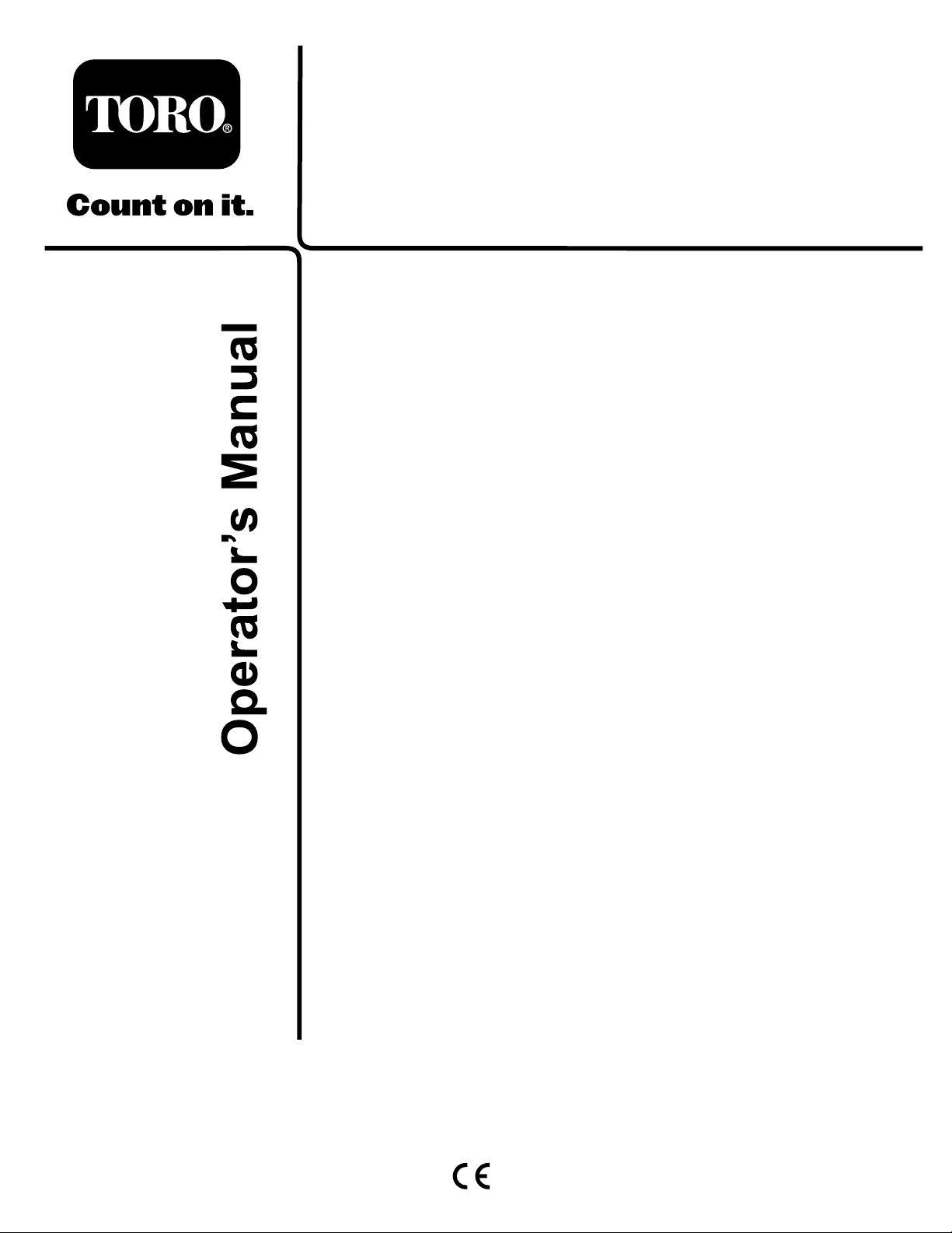
Safetydecalsandinstructionsareeasilyvisibletotheoperatorandarelocatednearanyareaofpotential
danger.Replaceanydecalthatisdamagedorlost.
93-6697
1.ReadtheOperator's
Manual.
1.Warning—readtheOperator'sManualforinstructionson
torquingthebladebolt/nutto115-149N-m(85-110ft-lb).
120-6604
2.AddSAE80w-90(API
GL-5)oilevery50hours.
93-7818
1.Thrownobjecthazard—keepbystandersawayfromthe
machine.
2.Cutting/dismembermenthazardofhand,mower
blade—stayawayfrommovingparts,keepallguardsand
shieldsinplace.
3.Cutting/dismembermenthazardoffoot,mowerblade—stay
awayfrommovingparts,keepallguardsandshieldsin
place.
93-6696
1.Storedenergyhazard—readtheOperator'sManual.
5
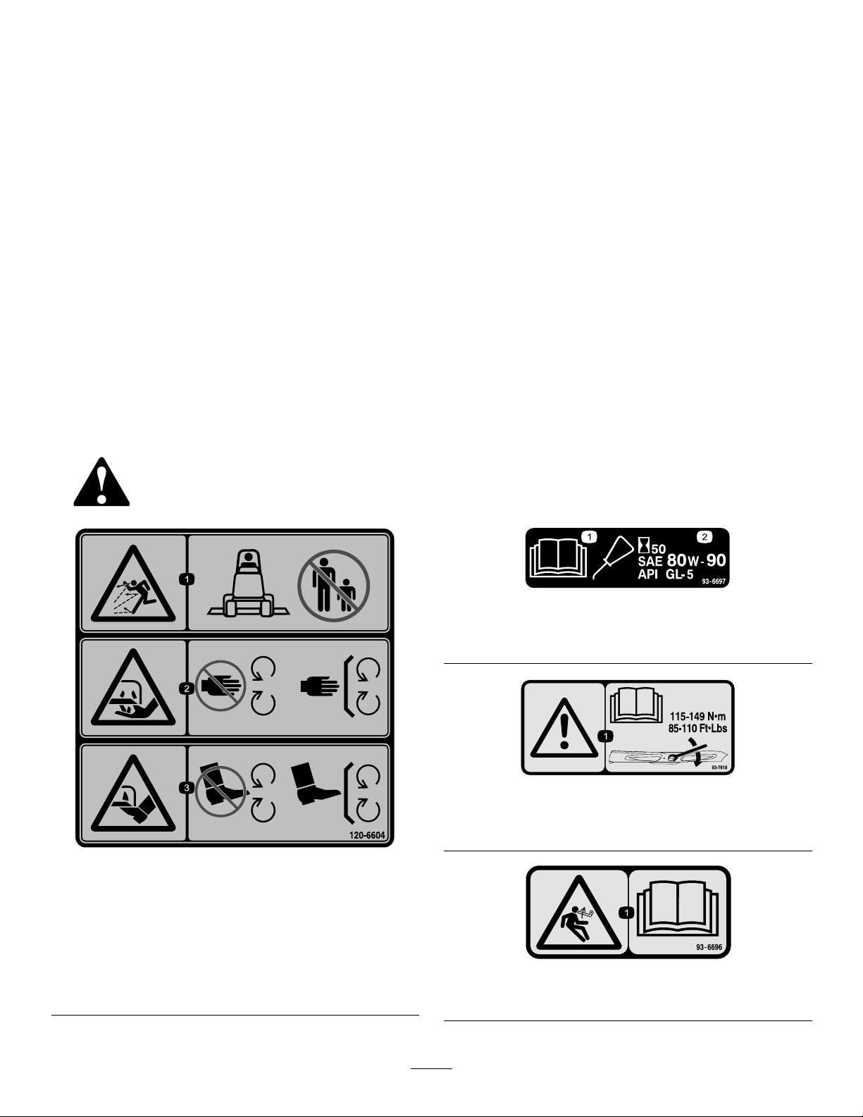
Page 6
1.Warning—nostep
119–6807
1.Rotatingbelt—Keepguardinplace
117–4979
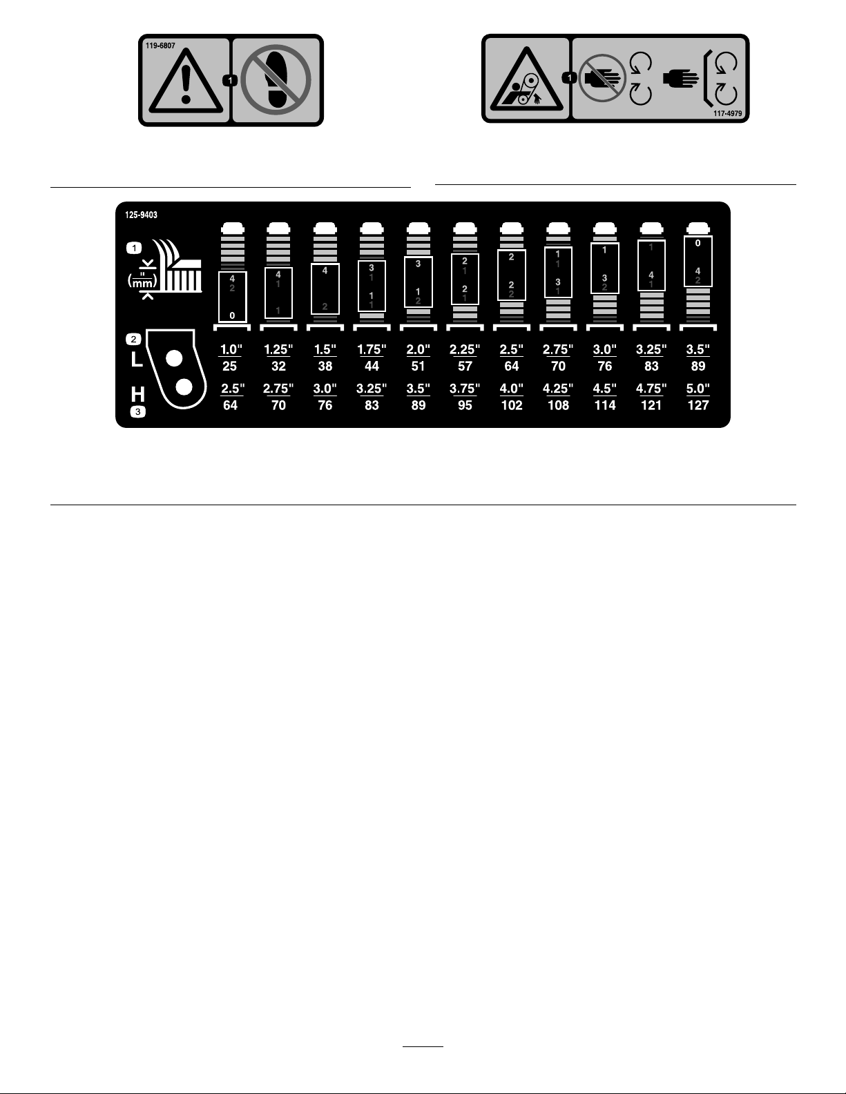
125-9403
1.Height-of-cut
2.Low
3.High
6
Page 7

Setup
MediaandAdditionalParts
Description
Operator'sManual
PartsCatalog
WARNING
Ifyouleavethekeyintheignitionswitch,someone
couldaccidentallystarttheengineandseriously
injureyouorotherbystanders.
Removethekeyfromtheignitionswitchbeforeyou
doanymaintenance.
DANGER
IftheengineisstartedandthePTOshaftisallowed
torotate,seriousinjurycouldresult.
DonotstarttheengineandengagethePTOswitch
whenthePTOshaftisnotconnectedtothegear
boxonthecuttingunit.
Note:Determinetheleftandrightsidesofthemachine
fromthenormaloperatingposition.
Note:The100inRearDischargeMowermustbeusedin
conjunctionwithoneofthefollowingadapterkits:
Qty.
1Reviewthematerialandsaveinanappropriateplace
1
Usetoreferencepartnumbers
Use
ProductOverview
Specications
Note:Specicationsanddesignaresubjecttochange
withoutnotice.
Widthof
Cut
Height
ofCut
Net
Weight
Attachments/Accessories
AselectionofToroapprovedattachmentsandaccessoriesis
availableforusewiththemachinetoenhanceandexpand
itscapabilities.ContactyourAuthorizedServiceDealeror
Distributororgotowww .T oro.comforalistofallapproved
attachmentsandaccessories.
2.54m(100inches)
Adjustablefrom25to127mm(1to5inches)in6
mm(1/4inch)increments
358kg(790lb.)
•AdapterKit,Model31102isfornon-cabGroundsmaster
®360SeriesTractionUnitswithmodelandserial
numbersinthefollowingranges:
31223–314000101thru314000104
30536–314000101thru314000105
30539–314000101thru3140001 16
•AdapterKit,Model31103isforGroundsmaster®360
SeriesTractionUnitswithmodelandserialnumbersin
thefollowingranges:
31223–314000105andUp
30536–314000106andup
30539–314000117andup
7
Page 8

Operation
4.Adjusttheanti-scalprollersandskidsasrequired.
Note:Determinetheleftandrightsidesofthemachine
fromthenormaloperatingposition.
CAUTION
Ifyouleavethekeyintheignitionswitch,someone
couldaccidentlystarttheengineandseriously
injureyouorotherbystanders.
Removethekeyfromtheignitionbeforeyoudoany
maintenance.
AdjustingtheHeight-of-Cut
Theheight-of-cutcanbeadjustedfrom25to127mm(1to5
inches)in6mm(1/4inch)increments.
CenterDeck
Theheight-of-cutonthecenterdeckisachievedbyrelocating
thestoppinintodifferentholelocations.
1.Withtheenginerunning,pushbackonthemowerlift
switchuntilthemowerisfullyraisedandreleasethe
switchimmediately.
2.Toadjust,rotatethestoppinuntilthenubonitlinesup
withtheslotsintheholesintheheight-of-cutbracket
andremoveit(
Figure2).
WingDecks
Theheight-of-cutonthewingdecksisachievedby
positioningthecastorwheelaxlesintheupperorlowerholes
ofthecastorforks,addorremoveanequalnumberofspacers
fromthecastorforksandsecuretheheightofcutcollarto
thedesiredholesintheheightofcutrod.
1.Starttheengineandraisethecuttingunitofftheoor
sothattheheight-of-cutcanbechanged.Stopthe
engineandremovethekeyafterthecuttingunitis
raised.
2.Positionthecastorwheelaxlesinthesameholesin
bothcastorforks.Referto
correctholesforthesetting.
Figure3todeterminethe
Figure2
1.Stoppin
3.Selectaholeintheheight-of-cutbracketcorresponding
totheheight-of-cutdesired,insertthepin,androtateit
downtolockitinplace(Figure2).
Note:Therearefourrowsofholepositions(
2).Thetoprowgivesyoutheheightofcutlistedabove
thepin.Thesecondrowdowngivesyoutheheight
listedplus6mm(1/4inch).Thethirdrowdown
givesyoutheheightlistedplus12mm(1/2inch).The
bottomrowgivesyoutheheightlistedplus18mm
(3/4inch).Forthe127mm(5inch)positionthereis
onlyonehole,locatedinthesecondrow .Thisdoesnot
add6mm(1/4inch)tothe127mm(5inch)position.
Figure3
1.Tensioningcap4.Axlemountingholes
2.Spacers5.CastorWheel
3.Shims
Note:Whenoperatingin64mm(2–1/2inch)height
ofcutorhigher,theaxleboltmustbeinstalledinthe
lowercastorforkholetopreventgrassbuildupbetween
thewheelandthefork.Whenoperatinginheightof
cutslowerthan64mm(2–1/2inch)andgrassbuildup
isdetected,reversethemachinesdirectiontopullany
clippingsawayfromthewheel/forkarea.
3.Removethetensioningcapfromthespindleshaft
(Figure3)andslidethespindleoutofthecastorarm.
Putthe2shims(1/8inch)ontothespindleshaftas
theywereoriginallyinstalled.Theseshimsarerequired
Figure
toachievealevelacrosstheentirewidthofthecutting
units.Slidetheappropriatenumberof1/2inchspacers
ontothespindleshafttogetthedesiredheight-of-cut;
thenslidethewasherontotheshaft.
Note:Whenusing25mm(1inch),38mm(1-1/2
inch),oroccasionally51mm(2inch)height–of–cut,
movetheskidsandrollertothehighestholes.
4.Securetheadjustmentwiththetensioningcap.
8
Page 9

AdjustingtheSkid(s)
Mounttheskidsinthelowerpositionwhenoperatingin
heightofcutshigherthan64mm(2-1/2inches)andinthe
higherpositionwhenoperatinginheightofcutslowerthan
64mm(2-1/2inches).
Note:Whentheskidsbecomeworn,youcanswitchtheskid
totheoppositesidesofthemower,ippingthemover.This
willallowyoutousetheskidslongerbeforereplacingthem.
1.DisengagethePTOandsettheparkingbrake.
2.MovethethrottlelevertotheSlowposition,stopthe
engine,removethekey,andwaitforallmovingpartsto
stopbeforeleavingtheoperatingposition.
Figure5
3.Loosenthescrewatthefrontofeachskid.(
Figure4
1.Skid
4.Removetheange-headboltsandnutsfromeachskid.
5.Moveeachskidtothedesiredpositionandsecurethem
withtheange-headboltsandnuts.
Note:Onlyusethetoporcentersetsofholesto
adjusttheskids.Thebottomholesareusedwhen
switchingsides,atwhichtimetheybecomethetop
holesontheothersideofthemower.
Figure4).
AdjustingtheRollers
Mounttherollersinthelowerpositionwhenoperatingin
heightofcutshigherthan64mm(2-1/2inches)andinthe
higherpositionwhenoperatinginheightofcutslowerthan
64mm(2-1/2inches).
1.Roller
5.Installthefastenersasillustrated.
2.Rollershaft
LevelingtheMower
LevelingFronttoBack
Cuttingunitpitchisthedifferenceinheight-of-cutfromthe
frontofthebladeplanetothebackofthebladeplane.Toro
recommendsabladepitchofapproximately8to11mm
(5/16to7/16inch).Thismeansthebackofthebladeplane
is8to11mm(5/16to7/16inch)higherthanthefront.
1.Positionthemachineonalevelsurfaceontheshop
oor.
2.Setthemowertothedesiredheight-of-cut,movethe
throttlelevertotheSlowposition,stoptheengine,set
theparkingbrake,andremovetheignitionkey.
3.Rotatethecenterbladesothatitpointsstraight
forward.
4.Usingashortruler,measurefromtheoortothefront
tipoftheblade.
5.Rotatethesamebladetiptotherearandmeasurefrom
theoortothetipofthebladeattherearofthemower.
6.Subtractthefrontdimensionfromthereardimension
tocalculatethebladepitch.
1.DisengagethePTOandsettheparkingbrake.
2.MovethethrottlelevertotheSlowposition,stopthe
engine,removethekey,andwaitforallmovingpartsto
stopbeforeleavingtheoperatingposition.
3.Raisethefrontofthemachineandsupportitonjack
stands.
4.Removethefastenerssecuringeachrolleronyour
mowerandmovetherollersupordownasdesired
(
Figure5).
7.AdjusttheU-boltjamnuts(Figure6)securingtherear
deckchains(Figure7)tothemowerdecktoraisethe
rearofthemowersothatthebladepitchissetto8to
11mm(5/16to7/16inch).
9
Page 10

6.Rotatethebladeoneachspindleuntiltheendsface
forwardandbackward.
7.Measurefromtheoortothefronttipofthecutting
edge
8.Adjustthejamnutssecuringthedeckchainstothe
mowerdeckuntilthemowerdeckislevel(
OperatingTips
Figure7).
Figure6
1.U-bolt2.Jamnut
FoldingCastorArm
Togainaccesstoorfromtheoperatorareawhenthewing
decksarefoldedup,releasethecastorarmlatch(Figure8)
androtatethecastorarmawayfromthetractionunit.
Figure8
1.Castorarmlatch
Important:Makesuretorotatethecastorarmbackto
thetractionunitbeforemowing.
Figure7
1.Leftrearliftchain2.Rightrearliftchain
LevelingSidetoSide
Ifthecutisunevenacrossthemowerswath,correctitas
follows:
1.Positionthemachineonalevelsurfaceontheshop
oor
2.Setthecuttingunittothedesiredheightofcut,move
thethrottlelevertotheSlowposition,stoptheengine,
settheparkingbrake,andremovetheignitionkey.
3.Checkandadjustfrontandreartractortirepressure;
refertoCheckingTirePressure.
4.Checkforbentblades.
5.Removethecoversfromthetopofthecuttingunits
TransportLatches
Beforetransportingthemachine,raisethecuttingunitsand
securethewingdecktransportlatches(Figure9).
Figure9
1.Wingdecktransportlatches
10
Page 11

FastThrottleSetting/GroundSpeed
Tomaintainenoughpowerforthemachineanddeckwhile
mowing,operatetheengineatthefastthrottlepositionand
adjustyourgroundspeedforconditions.Agoodruleto
followis:decreasegroundspeedastheloadonthecutting
bladesincreases;andincreasegroundspeedasloadonthe
bladesdecreases.
MowingDirection
Alternatemowingdirectiontoavoidmakingrutsintheturf
overtime.Thisalsohelpsdisperseclippingswhichenhances
decompositionandfertilization.
CuttingSpeed
Toimprovecutquality,useaslowergroundspeed.
SelecttheProperHeight-of-CutSetting
toSuitConditions
Removeapproximately25mm(1inch)ornomorethan1/3
ofthegrassbladewhencutting.Inexceptionallylushand
densegrass,youmayhavetoslowdowntheforwardspeed
and/orraisetheheight-of-cuttothenexthighersetting.
LongGrass
Ifthegrassiseverallowedtogrowslightlylongerthan
normal,orifitcontainsahighdegreeofmoisture,raisethe
cuttingheighthigherthanusualandcutthegrassatthis
setting.Thencutthegrassagainusingthelower,normal
setting.
KeeptheMowerClean
Cleanclippingsanddirtfromtheundersideofthemower
aftereachuse.Ifgrassanddirtbuildupinsidethemower,
cuttingqualitywilleventuallybecomeunsatisfactory.
Toreducetheriskofrehazard,keeptheengine,mufer,
batterycompartment,parkingbrake,cuttingunits,andfuel
storagecompartmentfreeofgrass,leaves,orexcessivegrease.
Cleanupanyspilledoilorfuel.
Usecompressedairoraleafblowertocleanthebeltdrive
area.Makesuretoinstallanyremovedguardsorcoverswhen
cleaninghasbeencompleted.
BladeMaintenance
Maintainasharpbladethroughoutthecuttingseasonbecause
asharpbladecutscleanlywithouttearingorshreddingthe
grassblades.Tearingandshreddingturnsgrassbrownat
theedges,whichslowsgrowthandincreasesthechanceof
disease.Checkthebladesdailyforsharpness,andforany
wearordamage.Sharpenthebladesasnecessary.Ifabladeis
damagedorworn,replaceitimmediatelywithagenuineToro
replacementblade.RefertoServicingtheCuttingBlades.
11
Page 12

Maintenance
RecommendedMaintenanceSchedule(s)
MaintenanceService
Interval
Aftertherst2hours
Aftertherst10hours
Aftertherst50hours
Beforeeachuseordaily
Every50hours
Every150hours
Every400hours
MaintenanceProcedure
•Tightenthecastorwheelnuts
•Tightenthecastorwheelnuts
•Changethemowerdeckgearboxlubricant
•Lubricatethecastorarmbushings
•Lubricatethecastorwheelbearings
•Checkthemowerblades.
•Lubricatethegreasettings
•Tightenthecastorwheelnuts
•Checkthelubricantinthemowerdeckgearbox.
•Changethemowerdeckgearboxlubricant
CAUTION
Ifyouleavethekeyintheignitionswitch,someonecouldaccidentallystarttheengineandseriously
injureyouorotherbystanders.
Removethekeyfromtheignitionswitchbeforeyoudoanymaintenance.
WARNING
Ifyouraisethemachineusingonlyajacktosupportitwhileyouworkunderthemowerdeck,thejack
couldtip,causingthemowerdecktofall,crushingyouorbystanders.
Alwayssecurethemachinewithatleast2jackstandswhenyouhavethemowerdeckraised.
12
Page 13

CAUTION
Onthetopofthemowerdeckaretwolinksthatconnectthemtotheframe.Connectedtotheselinksare
torsionspringsthatareundertension(
torsionspringwillbereleasedandcouldcausethelinkstomove,damagingyourhandsorngers.
Becarefulwhenremovingthemowerdeckfromtheframeandsecurethelinksbeforedisconnecting
themfromtheframe.
Figure10).Ifyoudisconnectthelinkthestoredenergyinthe
Figure10
1.Pulllink
2.Torsionspring5.Retainerpin
3.U-bolts
4.Deckliftchain
6.Shoulderscrew
13
Page 14

Lubrication
g025838
G025837
ServiceInterval:Every50hours
Themachinehasgreasettingsthatmustbelubricated
regularlywithNo.2GeneralPurposeLithiumBaseGrease.
Ifthemachineisoperatedundernormalconditions,lubricate
allbearingsandbushingsafterevery50hoursofoperationor
immediatelyaftereverywashing.
Lubricatethefollowingareas:
•Castorforkshaftbushings(4)(
Figure11)
Figure14
•Foldingcastorarmpivot(1)(Figure15)
Figure11
•Decklinks(5)(Figure12)
Figure12
•Idlerarmpivots(4)(Figure13)
Figure15
•PTODriveshaft(2)(Figure16)
Figure16
•Spindleshaftbearings(5)(Figure17)
Figure13
•Wingdeckhinges(10)(Figure14)
Figure17
14
Page 15

ServicingtheMowerDeck GearBoxLubricant
ThegearboxisdesignedtooperatewithSAE80-90gear
lube.Althoughthegearboxisshippedwithlubricantfrom
thefactory,checkthelevelbeforeoperatingthecuttingunit
forthersttimeandevery150operatinghoursthereafter.
Changethelubricantinthegearboxevery400operating
hours.
CheckingtheMowerDeckGearBox
Lubricant
ServiceInterval:Every150hours
1.Positionthemachineandcuttingunitonalevelsurface.
2.Lowerthemowerdecktothe2.5cm(1inch)
height-of-cut.
3.DisengagethePTO,releasethetractionpedalandset
theparkingbrake.
3.DisengagethePTO,releasethetractionpedalandset
theparkingbrake.
4.MovethethrottlelevertotheSlowposition,stopthe
engine,removethekey,andwaitforallmovingpartsto
stopbeforeleavingtheoperatingposition.
5.Liftthefootrest,exposingthetopofthemowerdeck.
6.Removethedipstick/llplugfromthetopofthegear
box(Figure18).
7.Placeadrainpanunderthedrainpluglocatedunder
thefrontofthegearboxandremovetheplug,draining
thelubricantintothepan.
8.Replacethedrainplug.
9.Addenoughlubricant,approximately414ml(14
ounces),untilthelevelisbetweenthemarksonthe
dipstick.
Note:Donotoverllorthegearboxmaybedamaged.
ServicingtheBushingsinthe
4.MovethethrottlelevertotheSlowposition,stopthe
engine,removethekey,andwaitforallmovingpartsto
stopbeforeleavingtheoperatingposition.
5.Liftthefootrest,exposingthetopofthemowerdeck.
6.Removethedipstick/llplugfromthetopofthegear
box(Figure18)andmakesurethatthelubricantis
betweenthemarksonthedipstick.
Figure18
1.Fillpluganddipstick2.Drainlocation
7.Ifthelubricantlevelislow ,addenoughlubricantuntil
thelevelisbetweenthemarksonthedipstick.
CastorArms
Thecastorarmshavebushingspressedintothetopand
bottomofthetubeandaftermanyhoursofoperation,the
bushingswillwear.Tocheckthebushings,movethecastor
forkbackandforthandfromsidetoside.Ifthecastor
spindleislooseinsidethebushings,thebushingsareworn
andmustbereplaced.
1.Raisethecuttingunitsothatthewheelsareoffof
theoor.Blockthecuttingunitsothatitcannot
accidentallyfall.
2.Removethetensioningcap,spacer(s),andthrust
washerfromthetopofthecastorspindle.
3.Pullthecastorspindleoutofthemountingtube.
Allowthethrustwasherandspacer(s)toremainon
thebottomofthespindle.
4.Insertapinpunchintothetoporbottomofthe
mountingtubeanddrivethebushingoutofthetube
(Figure19).Alsodrivetheotherbushingoutofthe
tube.Cleantheinsideofthetubestoremovedirt.
Note:Donotoverllorthegearboxmaybedamaged.
ChangingtheMowerDeckGearBox
Lubricant
ServiceInterval:Aftertherst50hours
Every400hours
1.Positionthemachineandcuttingunitonalevelsurface.
2.Lowerthemowerdecktothe2.5cm(1inch)
height-of-cut.
Figure19
1.Castorarmtube
5.Applygreasetotheinsideandoutsideofthenew
bushings.Usingahammerandatplate,drivethe
bushingsintothemountingtube.
15
2.Bushings
Page 16

6.Inspectthecastorspindleforwearandreplaceitif
damaged.
7.Pushthecastorspindlethroughthebushingsand
mountingtube.Slidethethrustwasherandspacer(s)
ontothespindle.Installthetensioningcaponthe
castorspindletoretainallpartsinplace.
ServicingtheCastorWheels andBearings
Checkthebladesdailyforsharpness,andforanywear
ordamage.Sharpenthebladesasnecessary.Ifabladeis
damagedorworn,replaceitimmediatelywithagenuineToro
replacementblade.
DANGER
Awornordamagedbladecanbreak,andapiece
ofthebladecouldbethrownintotheoperator's
orbystander'sarea,resultinginseriouspersonal
injuryordeath.
1.Removethelocknutfromtheboltholdingthecastor
wheelassemblybetweenthecastorfork(Figure20).
Graspthecastorwheelandslidetheboltoutofthe
forkorpivotarm.
Figure20
1.Castorwheel3.Bearing(2)
2.Castorfork
4.Bearingspacer
•Inspectthebladeperiodicallyforwearor
damage.
•Replaceawornordamagedblade.
Inspectandcheckthebladesevery8hours.
BeforeInspectingorServicingthe
Blades
1.DisengagethePTO,releasethetractionpedalandset
theparkingbrake.
2.MovethethrottlelevertotheSlowposition,stopthe
engine,removethekey,andwaitforallmovingpartsto
stopbeforeleavingtheoperatingposition.
InspectingtheBlades
ServiceInterval:Beforeeachuseordaily
1.Inspectthecuttingedges(
arenotsharporhavenicks,removeandsharpenthe
blades.RefertoSharpeningtheBlades.
Figure21).Iftheedges
2.Removethebearingfromthewheelhubandallow
thebearingspacertofallout(
bearingfromtheoppositesideofthewheelhub.
3.Checkthebearings,spacer,andinsideofthewheelhub
forwear.Replaceanydamagedparts.
4.Toassemblethecastorwheel,pushthebearingintothe
wheelhub.Wheninstallingthebearings,pressonthe
outerraceofthebearing.
5.Slidethebearingspacerintothewheelhub.Pushthe
otherbearingintotheopenendofthewheelhubto
captivatethebearingspacerinsidethewheelhub.
6.Installthecastorwheelassemblybetweenthecastor
forkandsecureitinplacewiththeboltandlocknut.
Figure20).Removethe
ServicingtheCuttingBlades
Maintainsharpbladesthroughoutthecuttingseasonbecause
sharpbladescutcleanlywithouttearingorshreddingthegrass
blades.Tearingandshreddingturnsgrassbrownattheedges,
whichslowsgrowthandincreasesthechanceofdisease.
2.Inspecttheblades,especiallythesailarea(Figure21).
Ifyounoticeanydamage,wear,oraslotformingin
thisarea(Figure21),immediatelyinstallanewblade.
DANGER
Ifyouallowthebladetowear,aslotwillform
betweenthesailandatpartoftheblade.
Eventuallyapieceoftheblademaybreak
offandbethrownfromunderthehousing,
possiblyresultinginseriousinjuryordeath
toyouorbystanders.
•Inspectthebladeperiodicallyforwearor
damage.
•Nevertrytostraightenabladethatisbent
orweldabrokenorcrackedblade.
•Replaceawornordamagedblade.
16
Page 17

Figure22
Figure21
1.CuttingEdge3.Wear/slotForming
2.SailArea4.Crack
CheckingforBentBlades
1.DisengagethePTO,releasethetractionpedalandset
theparkingbrake.
2.MovethethrottlelevertotheSlowposition,stopthe
engine,removethekey,andwaitforallmovingpartsto
stopbeforeleavingtheoperatingposition.
3.Rotatethebladesuntiltheendsfaceforwardand
backward(
thecuttingedge,positionA,oftheblades(Figure22).
Notethisdimension.
Figure22).Measurefromalevelsurfaceto
1.PositionA
4.Rotatetheoppositeendsofthebladesforward.
5.Measurefromalevelsurfacetothecuttingedgeof
thebladesatthesamepositionasinstep3above.
Thedifferencebetweenthedimensionsobtainedin
steps3and4mustnotexceed3mm(1/8inch).Ifthis
dimensionexceeds3mm(1/8inch),thebladeisbent
andmustbereplaced;refertoRemovingtheBlades
andInstallingtheBlades.
2.Measureherefromblade
tohardsurface
WARNING
Abladethatisbentordamagedcouldbreak
apartandcouldseriouslyinjureorkillyouor
bystanders.
•Alwaysreplacebentordamagedblade
withanewblade.
•Neverleorcreatesharpnotchesinthe
edgesorsurfacesofblade.
RemovingtheBlades
Bladesmustbereplacedifasolidobjectishit,ifthebladeis
outofbalanceorisbent.Toensureoptimumperformance
andcontinuedsafetyconformanceofthemachine,use
genuineT ororeplacementblades.Replacementbladesmade
byothermanufacturersmayresultinnon-conformancewith
safetystandards.
WARNING
Contactwithasharpbladecancauseseriousinjury.
Wearglovesorwrapsharpedgesofthebladewith
arag.
1.Holdthebladeendusingaragorthickly-paddedglove.
2.Removethebladebolt,anti-scalpplate,andbladefrom
thespindleshaft(
17
Figure25).
Page 18

SharpeningtheBlades
WARNING
Whensharpeningblade,piecesofbladecouldbe
thrownandcauseseriousinjury.
Wearpropereyeprotectionwhensharpening
blades.
1.Sharpenthecuttingedgeatbothendsoftheblade
(Figure23).Maintaintheoriginalangle.Theblade
retainsitsbalanceifthesameamountofmaterialis
removedfrombothcuttingedges.
Figure23
1.Sharpenatoriginalangle
2.Checkthebalanceofthebladebyputtingitonablade
balancer(
Figure24).Ifthebladestaysinahorizontal
position,thebladeisbalancedandcanbeused.Ifthe
bladeisnotbalanced,lesomemetalofftheendof
thesailareaonly(Figure25).Repeatthisprocedure
untilthebladeisbalanced.
Figure24
1.Blade2.Balancer
InstallingtheBlades
Note:The2wingdeckbladesarenotthesameasthe3
centerblades.
1.Installthebladeontothespindleshaft(Figure25).
Important:Thecurvedpartoftheblademustbe
pointingupwardtowardtheinsideofthemowerto
ensurepropercutting.
Figure25
1.Spindle
2.SailAreaofBlade
3.Anti-scalpplate
4.BladeBolt
3.Torquethebladeboltto115-150N⋅m(85-110ft-lb).
2.Installtheanti-scalpplateandbladebolt(Figure25).
18
Page 19

DeclarationofIncorporation
TheT oroCompany,8111LyndaleAve.South,Bloomington,MN,USAdeclaresthatthefollowingunit(s)
conform(s)tothedirectiveslisted,wheninstalledinaccordancewiththeaccompanyinginstructionsontocertain
ToromodelsasindicatedontherelevantDeclarationsofConformity.
ModelNo.
31101314000001andUp100inRearDischargeMower
SerialNo.
ProductDescriptionInvoiceDescription
CUTTINGUNIT -100IN,
GM360
GeneralDescription
100inRearDischargeMower
Directive
2006/42/EC,
2000/14/EC
RelevanttechnicaldocumentationhasbeencompiledasrequiredperPartBofAnnexVIIof2006/42/EC.
Wewillundertaketotransmit,inresponsetorequestsbynationalauthorities,relevantinformationonthispartly
completedmachinery.Themethodoftransmissionshallbeelectronictransmittal.
ThismachineryshallnotbeputintoserviceuntilincorporatedintoapprovedToromodelsasindicatedonthe
associatedDeclarationofConformityandinaccordancewithallinstructions,wherebyitcanbedeclaredin
conformitywithallrelevantDirectives.
Certied:EUTechnicalContact:
PeterT etteroo
ToroEuropeNV
B-2260Oevel-Westerloo
Belgium
DavidKlisTel.003214562960
Sr.EngineeringManager
811 1LyndaleAve.South
Bloomington,MN55420,USA
September26,2013
Fax003214581911
19
Page 20

TheToroTotalCoverageGuarantee
ALimitedWarranty
ConditionsandProductsCovered
TheToroCompanyanditsafliate,T oroWarrantyCompany,pursuant
toanagreementbetweenthem,jointlywarrantyourToroCommercial
product(“Product”)tobefreefromdefectsinmaterialsorworkmanship
fortwoyearsor1500operationalhours*,whicheveroccursrst.This
warrantyisapplicabletoallproductswiththeexceptionofAerators
(refertoseparatewarrantystatementsfortheseproducts).Wherea
warrantableconditionexists,wewillrepairtheProductatnocosttoyou
includingdiagnostics,labor,parts,andtransportation.Thiswarranty
beginsonthedatetheProductisdeliveredtotheoriginalretailpurchaser.
*Productequippedwithanhourmeter.
InstructionsforObtainingWarrantyService
YouareresponsiblefornotifyingtheCommercialProductsDistributoror
AuthorizedCommercialProductsDealerfromwhomyoupurchasedthe
Productassoonasyoubelieveawarrantableconditionexists.Ifyouneed
helplocatingaCommercialProductsDistributororAuthorizedDealer,or
ifyouhavequestionsregardingyourwarrantyrightsorresponsibilities,
youmaycontactusat:
ToroCommercialProductsServiceDepartment
ToroWarrantyCompany
811 1LyndaleAvenueSouth
Bloomington,MN55420-1196
952–888–8801or800–952–2740
E-mail:commercial.warranty@toro.com
OwnerResponsibilities
AstheProductowner,youareresponsibleforrequiredmaintenance
andadjustmentsstatedinyourOperator'sManual.Failuretoperform
requiredmaintenanceandadjustmentscanbegroundsfordisallowinga
warrantyclaim.
ItemsandConditionsNotCovered
Notallproductfailuresormalfunctionsthatoccurduringthewarranty
periodaredefectsinmaterialsorworkmanship.Thiswarrantydoesnot
coverthefollowing:
•Productfailureswhichresultfromtheuseofnon-Tororeplacement
parts,orfrominstallationanduseofadd-on,ormodiednon-T oro
brandedaccessoriesandproducts.Aseparatewarrantymaybe
providedbythemanufactureroftheseitems.
•Productfailureswhichresultfromfailuretoperformrecommended
maintenanceand/oradjustments.Failuretoproperlymaintainyour
ToroproductpertheRecommendedMaintenancelistedinthe
Operator’sManualcanresultinclaimsforwarrantybeingdenied.
•ProductfailureswhichresultfromoperatingtheProductinan
abusive,negligent,orrecklessmanner.
•Partssubjecttoconsumptionthroughuseunlessfoundtobe
defective.Examplesofpartswhichareconsumed,orusedup,
duringnormalProductoperationinclude,butarenotlimitedto,brake
padsandlinings,clutchlinings,blades,reels,rollersandbearings
(sealedorgreasable),bedknives,sparkplugs,castorwheelsand
bearings,tires,lters,belts,andcertainsprayercomponentssuchas
diaphragms,nozzles,andcheckvalves,etc.
•Failurescausedbyoutsideinuence.Conditionsconsideredtobe
outsideinuenceinclude,butarenotlimitedto,weather,storage
practices,contamination,useofunapprovedfuels,coolants,
lubricants,additives,fertilizers,water,orchemicals,etc.
•Failureorperformanceissuesduetotheuseoffuels(e.g.gasoline,
diesel,orbiodiesel)thatdonotconformtotheirrespectiveindustry
standards.
•Normalnoise,vibration,wearandtear,anddeterioration.
•Normal“wearandtear”includes,butisnotlimitedto,damageto
seatsduetowearorabrasion,wornpaintedsurfaces,scratched
decalsorwindows,etc.
Parts
Partsscheduledforreplacementasrequiredmaintenancearewarranted
fortheperiodoftimeuptothescheduledreplacementtimeforthatpart.
Partsreplacedunderthiswarrantyarecoveredforthedurationofthe
originalproductwarrantyandbecomethepropertyofT oro.Torowill
makethenaldecisionwhethertorepairanyexistingpartorassemblyor
replaceit.T oromayuseremanufacturedpartsforwarrantyrepairs.
DeepCycleandLithium-IonBatteryWarranty:
DeepcycleandLithium-Ionbatterieshaveaspeciedtotalnumberof
kilowatt-hourstheycandeliverduringtheirlifetime.Operating,recharging,
andmaintenancetechniquescanextendorreducetotalbatterylife.Asthe
batteriesinthisproductareconsumed,theamountofusefulworkbetween
chargingintervalswillslowlydecreaseuntilthebatteryiscompletelyworn
out.Replacementofwornoutbatteries,duetonormalconsumption,
istheresponsibilityoftheproductowner.Batteryreplacementmaybe
requiredduringthenormalproductwarrantyperiodatowner’sexpense.
Note:(Lithium-Ionbatteryonly):ALithium-Ionbatteryhasapartonly
proratedwarrantybeginningyear3throughyear5basedonthetime
inserviceandkilowatthoursused.RefertotheOperator'sManualfor
additionalinformation.
MaintenanceisatOwner’sExpense
Enginetune-up,lubrication,cleaningandpolishing,replacementoflters,
coolant,andcompletingrecommendedmaintenancearesomeofthe
normalservicesT oroproductsrequirethatareattheowner’sexpense.
GeneralConditions
RepairbyanAuthorizedT oroDistributororDealerisyoursoleremedy
underthiswarranty.
NeitherTheToroCompanynorT oroWarrantyCompanyisliablefor
indirect,incidentalorconsequentialdamagesinconnectionwiththe
useoftheToroProductscoveredbythiswarranty ,includingany
costorexpenseofprovidingsubstituteequipmentorserviceduring
reasonableperiodsofmalfunctionornon-usependingcompletion
ofrepairsunderthiswarranty.ExceptfortheEmissionswarranty
referencedbelow,ifapplicable,thereisnootherexpresswarranty .
Allimpliedwarrantiesofmerchantabilityandtnessforuseare
limitedtothedurationofthisexpresswarranty .
Somestatesdonotallowexclusionsofincidentalorconsequential
damages,orlimitationsonhowlonganimpliedwarrantylasts,sothe
aboveexclusionsandlimitationsmaynotapplytoyou.Thiswarranty
givesyouspeciclegalrights,andyoumayalsohaveotherrightswhich
varyfromstatetostate.
Noteregardingenginewarranty:
TheEmissionsControlSystemonyourProductmaybecoveredby
aseparatewarrantymeetingrequirementsestablishedbytheU.S.
EnvironmentalProtectionAgency(EPA)and/ortheCaliforniaAir
ResourcesBoard(CARB).Thehourlimitationssetforthabovedonot
applytotheEmissionsControlSystemWarranty.RefertotheEngine
EmissionControlWarrantyStatementsuppliedwithyourproductor
containedintheenginemanufacturer’sdocumentationfordetails
CountriesOtherthantheUnitedStatesorCanada
CustomerswhohavepurchasedT oroproductsexportedfromtheUnitedStatesorCanadashouldcontacttheirT oroDistributor(Dealer)toobtain
guaranteepoliciesforyourcountry ,province,orstate.IfforanyreasonyouaredissatisedwithyourDistributor'sserviceorhavedifcultyobtaining
guaranteeinformation,contacttheT oroimporter.
374-0253RevB
 Loading...