

Page 1
FormNo.3401-829RevA
Groundsmaster
®
4500-Dand
4700-DTractionUnit
ModelNo.30881—SerialNo.315000001andUp
ModelNo.30881A—SerialNo.315000001andUp
ModelNo.30882—SerialNo.315000001andUp
ModelNo.30882A—SerialNo.315000001andUp
Registeratwww.T oro.com.
OriginalInstructions(EN)
*3401-829*A
Page 2
ThisproductcomplieswithallrelevantEuropeandirectives,
fordetailspleaseseetheseparateproductspecicDeclaration
ofConformity(DOC)sheet.
WARNING
CALIFORNIA
Proposition65Warning
Thisproductcontainsachemicalorchemicals
knowntotheStateofCaliforniatocausecancer,
birthdefects,orreproductiveharm.
Dieselengineexhaustandsomeofits
constituentsareknowntotheStateof
Californiatocausecancer,birthdefects,
andotherreproductiveharm.
GenuineT orosparkarrestersareapprovedbytheUSDA
ForestryService.
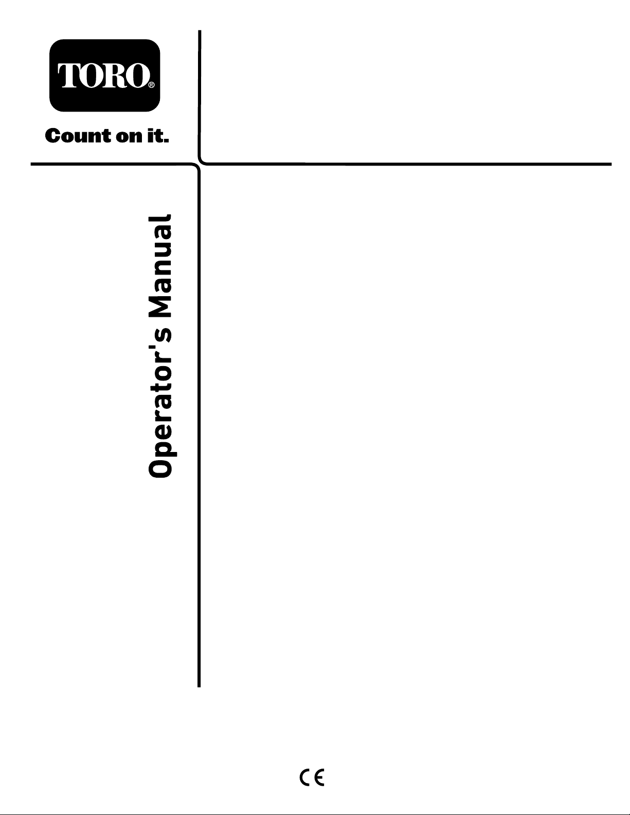
CustomerServiceandhavethemodelandserialnumbersof
yourproductready.Figure1identiesthelocationofthe
modelandserialnumbersontherightfrontframemember
oftheproduct.Writethenumbersinthespaceprovided.
ItisaviolationofCaliforniaPublicResourceCode
Section4442or4443touseoroperatetheengineonany
forest-covered,brush-covered,orgrass-coveredlandunless
theengineisequippedwithasparkarrester,asdenedin
Section4442,maintainedineffectiveworkingorderorthe
engineisconstructed,equipped,andmaintainedforthe
preventionofre.
ThissparkignitionsystemcomplieswithCanadianICES-002
Theenclosed
Engine Owner's Man ual
issuppliedfor
informationregardingtheUSEnvironmentalProtection
Agency(EPA)andtheCaliforniaEmissionControl
Regulationofemissionsystems,maintenance,and
warranty.Replacementsmaybeorderedthroughthe
enginemanufacturer.
Introduction
Thismachineisaride-on,rotary-bladelawnmowerintended
tobeusedbyprofessional,hiredoperatorsincommercial
applications.Itisprimarilydesignedforcuttinggrasson
well-maintainedlawnsinparks,golfcourses,sportselds,
andoncommercialgrounds.Itisnotdesignedforcutting
brush,mowinggrassandothergrowthalongsidehighways,
orforagriculturaluses.
Figure1
1.Modelandserialnumberlocation
ModelNo.
SerialNo.
Thismanualidentiespotentialhazardsandhassafety
messagesidentiedbythesafety-alertsymbol(Figure2),
whichsignalsahazardthatmaycauseseriousinjuryordeath
ifyoudonotfollowtherecommendedprecautions.
Figure2
1.Safety-alertsymbol.
Thismanualuses2wordstohighlightinformation.
Importantcallsattentiontospecialmechanicalinformation
andNoteemphasizesgeneralinformationworthyofspecial
attention.
Readthisinformationcarefullytolearnhowtooperateand
maintainyourproductproperlyandtoavoidinjuryand
productdamage.Youareresponsibleforoperatingthe
productproperlyandsafely.
YoumaycontactTorodirectlyatwww .Toro.comforproduct
safetyandoperationtrainingmaterials,accessoryinformation,
helpndingadealer,ortoregisteryourproduct.
Wheneveryouneedservice,genuineT oroparts,oradditional
information,contactanAuthorizedServiceDealerorToro
©2015—TheToro®Company
8111LyndaleAvenueSouth
Bloomington,MN55420
Contactusatwww.Toro.com.
2
PrintedintheUSA
AllRightsReserved
Page 3

Contents
Safety...........................................................................4
GeneralSafety.........................................................4
SoundPowerLevel..................................................4
SoundPressureLevel...............................................4
VibrationLevel......................................................4
EngineEmissionCertication...................................4
SafetyandInstructionalDecals.................................5
Setup...........................................................................10
1InstallingtheHoodLatch(CEOnly).......................11
2AdjustingtheRollerScraper(Optional)...................11
3InstallingtheMulchingBafe(Optional).................12
4PreparingtheMachine..........................................13
ProductOverview.........................................................13
Controls...............................................................13
Specications........................................................20
Attachments/Accessories........................................20
BeforeOperation......................................................21
BeforeOperationSafety..........................................21
CheckingtheEngine-OilLevel.................................22
CheckingtheCoolingSystem...................................22
CheckingtheHydraulicSystem................................22
FillingtheFuelTank...............................................22
CheckingtheTirePressure......................................23
CheckingtheTorqueoftheWheelNuts.....................23
AdjustingtheHeightofCut.....................................23
CheckingtheInterlockSwitches...............................24
CheckingtheBlade-StoppingTime...........................24
SelectingaBlade.....................................................24
ChoosingAccessories.............................................25
DuringOperation.....................................................26
DuringOperationSafety.........................................26
StartingandStoppingtheEngine..............................27
UnderstandingtheOperatingCharacteristicsofthe
Machine............................................................27
OperatingtheEngine-CoolingFan...........................27
OperatingTips......................................................28
AfterOperation........................................................29
AfterOperationSafety............................................29
JackingPoints........................................................29
TieDowns............................................................29
PushingorTowingtheMachine................................29
HaulingtheMachine...............................................29
Maintenance.................................................................30
RecommendedMaintenanceSchedule(s)......................30
DailyMaintenanceChecklist....................................31
ServiceIntervalChart.............................................32
PremaintenanceProcedures........................................33
RemovingtheHood...............................................33
Lubrication...............................................................33
GreasingtheBearingsandBushings..........................33
EngineMaintenance..................................................35
EngineSafety.........................................................35
ServicingtheAirCleaner.........................................35
ServicingtheEngineOil..........................................36
ServicingtheDieselParticulateFilter(DPF)...............37
ServicingtheDieselOxidationCatalyst
(DOC)..............................................................37
FuelSystemMaintenance...........................................38
DrainingtheFuelTank...........................................38
InspectingtheFuelLinesandConnections.................38
ServicingtheWaterSeparator...................................38
ServicingtheFuelFilter...........................................39
ServicingtheFuel-PickupTube................................39
ElectricalSystemMaintenance....................................39
ChargingandConnectingtheBattery........................39
ServicingtheBattery...............................................41
Fuses....................................................................41
DriveSystemMaintenance.........................................42
CheckingforEnd-PlayinthePlanetary
Drives...............................................................42
CheckingthePlanetaryGearDriveOil......................42
ChangingthePlanetaryGearDriveOil......................42
CheckingtheRearAxleLubricant.............................43
ChangingtheRearAxleLubricant.............................43
CheckingtheRearAxleGearBoxLubricant...............44
CheckingtheRearWheelT oe-In..............................44
CoolingSystemMaintenance......................................45
CoolingSystemSafety.............................................45
CheckingtheCoolingSystem...................................45
CleaningtheCoolingSystem....................................45
BrakeMaintenance....................................................46
AdjustingtheServiceBrakes....................................46
BeltMaintenance......................................................47
ServicingtheAlternatorBelt....................................47
HydraulicSystemMaintenance....................................47
HydraulicSystemSafety..........................................47
CheckingtheHydraulic-FluidLevel..........................47
ChangingtheHydraulicFluid...................................49
ReplacingtheHydraulicFilters.................................49
CheckingtheHydraulicLinesandHoses....................50
CuttingDeckMaintenance..........................................50
SeparatingtheCuttingDecksfromtheTraction
Unit..................................................................50
MountingtheCuttingDeckstotheTraction
Unit..................................................................51
ServicingtheBladePlane.........................................51
ServicingtheCutterBlade.......................................52
ServicingtheFrontRoller........................................53
Storage........................................................................54
PreparingtheTractionUnit.....................................54
PreparingtheEngine..............................................54
CuttingDeck.........................................................54
3
Page 4

Safety
ThismachinehasbeendesignedinaccordancewithENISO
5395:2013andANSIB71.4-2012.
GeneralSafety
SoundPowerLevel
Thisunithasaguaranteedsoundpowerlevelof105dBA,
whichincludesanUncertaintyValue(K)of0.7dBA.
Soundpowerlevelwasdeterminedaccordingtothe
proceduresoutlinedinISO11094.
Thisproductiscapableofamputatinghandsandfeetand
ofthrowingobjects.Alwaysfollowallsafetyinstructionsto
avoidseriouspersonalinjury.
Usingthisproductforpurposesotherthanitsintendeduse
couldprovedangeroustoyouandbystanders.
•ReadandunderstandthecontentsofthisOperator’ sManual
beforeyoustarttheengine.Ensurethateveryoneusing
thisproductknowshowtouseitandunderstandsthe
warnings.
•Donotputyourhandsorfeetnearmovingcomponents
ofthemachine.
•Donotoperatethemachinewithoutallguardsandother
safetyprotectivedevicesinplaceandworkingonthe
machine.
•Keepclearofanydischargeopening.Keepbystandersa
safedistancefromthemachine.
•Keepchildrenoutoftheoperatingarea.Neverallow
childrentooperatethemachine.
•Stopthemachineandshutofftheenginebeforeservicing,
fueling,oruncloggingthemachine.
Improperlyusingormaintainingthismachinecanresult
ininjury.T oreducethepotentialforinjury,complywith
thesesafetyinstructionsandalwayspayattentiontothe
safety-alertsymbol,whichmeansCaution,Warning,or
Danger—personalsafetyinstruction.Failuretocomplywith
theseinstructionsmayresultinpersonalinjuryordeath.
Youcanndadditionalitemsofsafetyinformationintheir
respectivesectionsthroughoutthismanual.
SoundPressureLevel
Thisunithasasoundpressurelevelattheoperator’searof90
dBA,whichincludesanUncertaintyValue(K)of0.7dBA.
Soundpressurelevelwasdeterminedaccordingtothe
proceduresoutlinedinENISO5395:2013.
VibrationLevel
Hand-Arm
Measuredvibrationlevelforrighthand=0.6m/s
Measuredvibrationlevelforlefthand=0.7m/s
UncertaintyValue(K)=0.3m/s
Measuredvaluesweredeterminedaccordingtotheprocedures
outlinedinENISO5395:2013.
WholeBody
Measuredvibrationlevel=0.2m/s
UncertaintyValue(K)=0.1m/s
Measuredvaluesweredeterminedaccordingtotheprocedures
outlinedinENISO5395:2013.
2
2
2
2
2
EngineEmissionCertication
TheengineinthismachineisEPATier4Finalandstage3b
compliant.
4
Page 5
SafetyandInstructionalDecals
Safetydecalsandinstructionsareeasilyvisibletotheoperatorandarelocatednearanyareaofpotential
danger.Replaceanydecalthatisdamagedorlost.
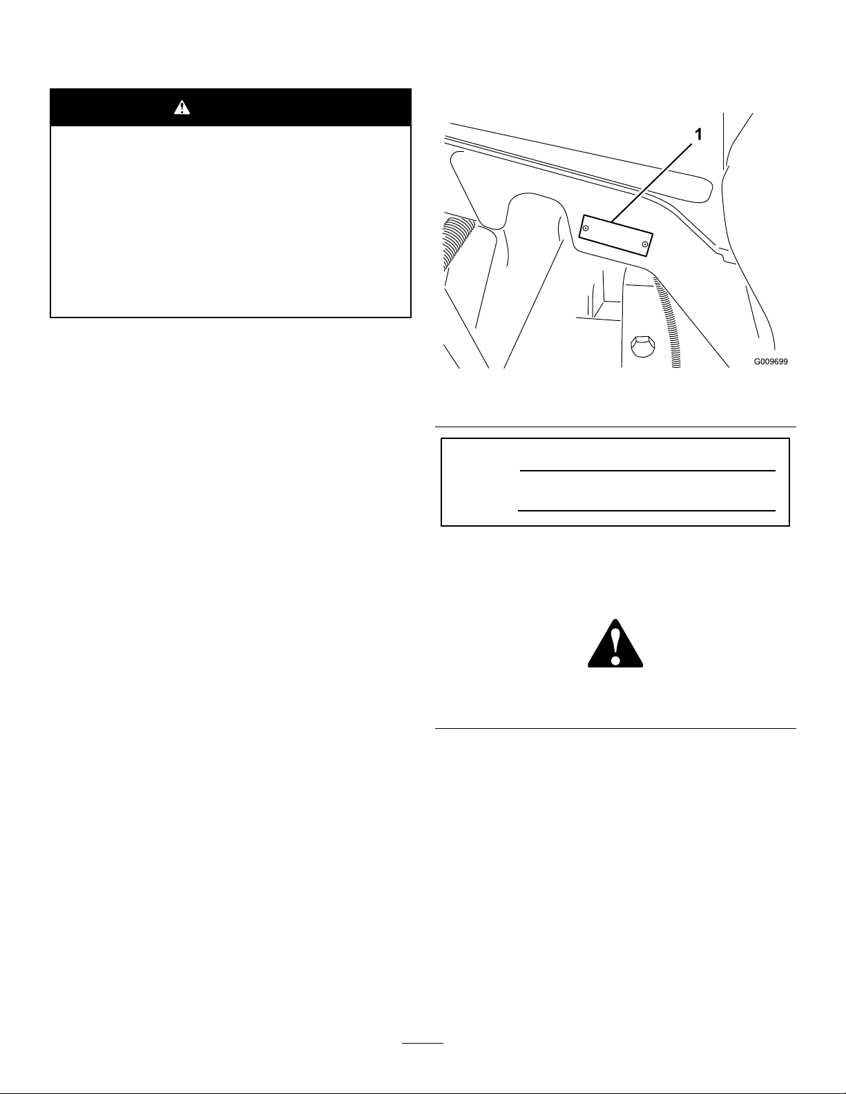
93-6681
1.Cutting/dismemberment—hazard,fan-stayawayfrom
movingparts.
106-6755
93-7272
1.Cutting/dismembermenthazard;fan—stayawayfrom
movingparts.
93-7818
1.Warning—readtheOperator'sManualforinstructionson
torquingthebladebolt/nutto1 15to149N-m(85to110
ft-lb).
98-4387
1.Warning—wearhearingprotection.
106-6754
1.Warning—donottouchthehotsurface.
2.Cutting/dismembermenthazard,fanandentanglement
hazard,belt—stayawayfrommovingparts.
1.Enginecoolantunder
pressure.
2.Explosionhazard—read
theOperator'sManual.
3.Warning—donottouchthe
hotsurface.
4.Warning—readthe
Operator'sManual.
112-5019
112-5297
1.Warning—readtheOperator'sManual,donotoperatethis
machineunlessyouaretrained.
2.Warning—readtheOperator'sManualbeforetowingthe
machine.
3.Tippinghazard—slowmachinebeforeturning,donotturn
athighspeeds;lowerthecuttingunitwhendrivingdown
slopes;usearolloverprotectionsystemandweartheseat
belt
4.Warning—donotparkthemachineonslopes;engagethe
parkingbrake,lowerthecuttingunits,shutofftheengine,
andremovetheignitionkeybeforeleavingthemachine.
5.Thrownobjecthazard—keepbystandersasafedistance
fromthemachine.
6.Entanglementhazard,belt—stayawayfrommovingparts,
keepallguardsandshieldsinplace.
5
Page 6
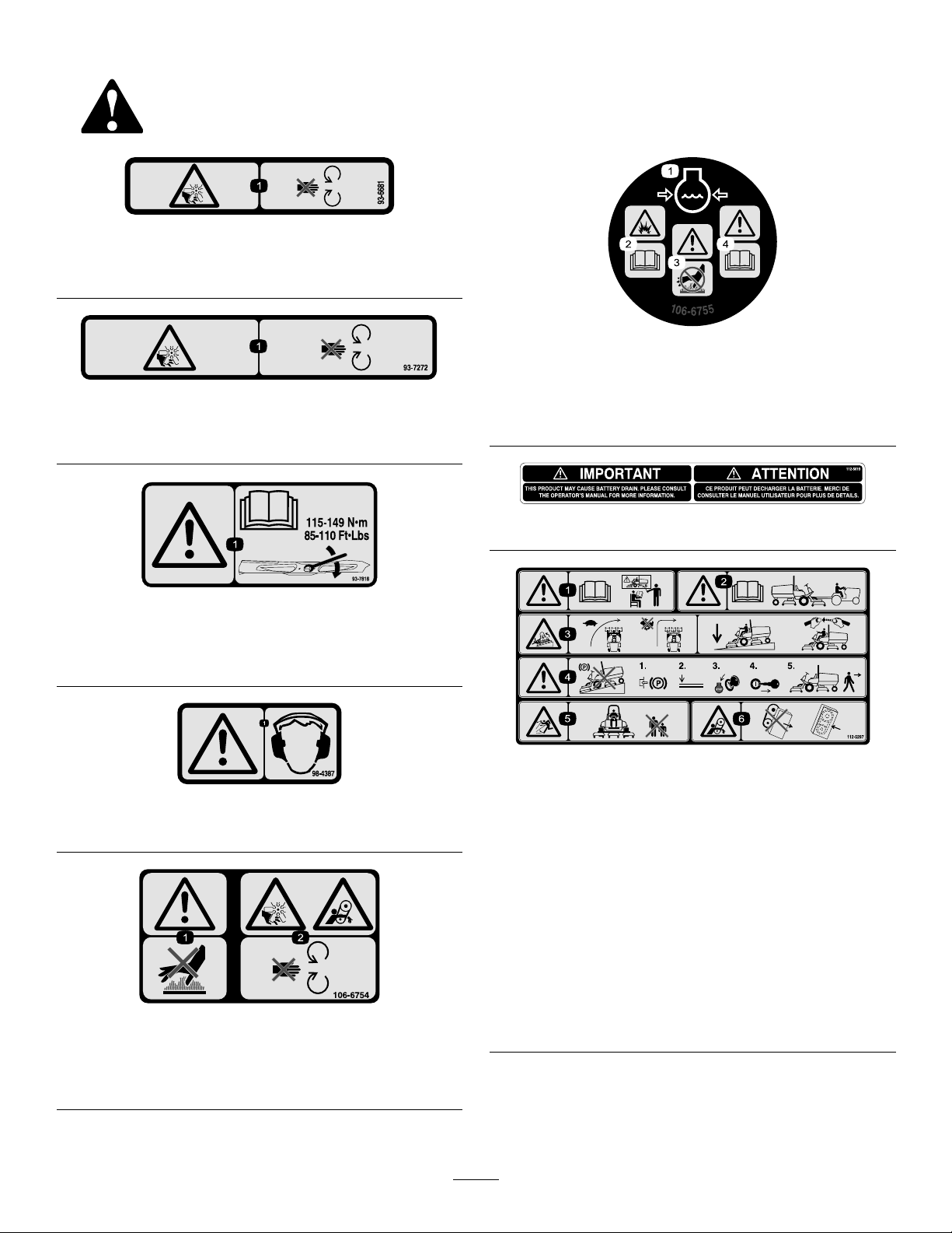
112-5298
(PlaceoverPartNo.112-5297forCE*)
*Thissafetydecalincludesaslopewarningrequiredonthemachinefor
compliancetotheEuropeanLawnMowerSafetyStandardEN836:1997.The
conservativemaximumslopeanglesindicatedforoperationofthismachineare
prescribedbyandrequiredbythisstandard.
1.Warning—readtheOperator'sManual,donotoperatethis
machineunlessyouaretrained.
2.Warning—readtheOperator'sManualbeforetowingthe
machine.
3.Tippinghazard—donotoperateonslopesgreaterthan15°;
lowerthecuttingunitswhenoperatingonslopes;wearthe
safetybelt.
4.Warning—donotparkthemachineonslopes;engagethe
parkingbrake,lowerthecuttingunits,shutofftheengine,
andremovetheignitionkeybeforeleavingthemachine.
5.Thrownobjecthazard—keepbystandersasafedistance
fromthemachine.
6.Entanglementhazard,belt—stayawayfrommovingparts,
keepallguardsandshieldsinplace.
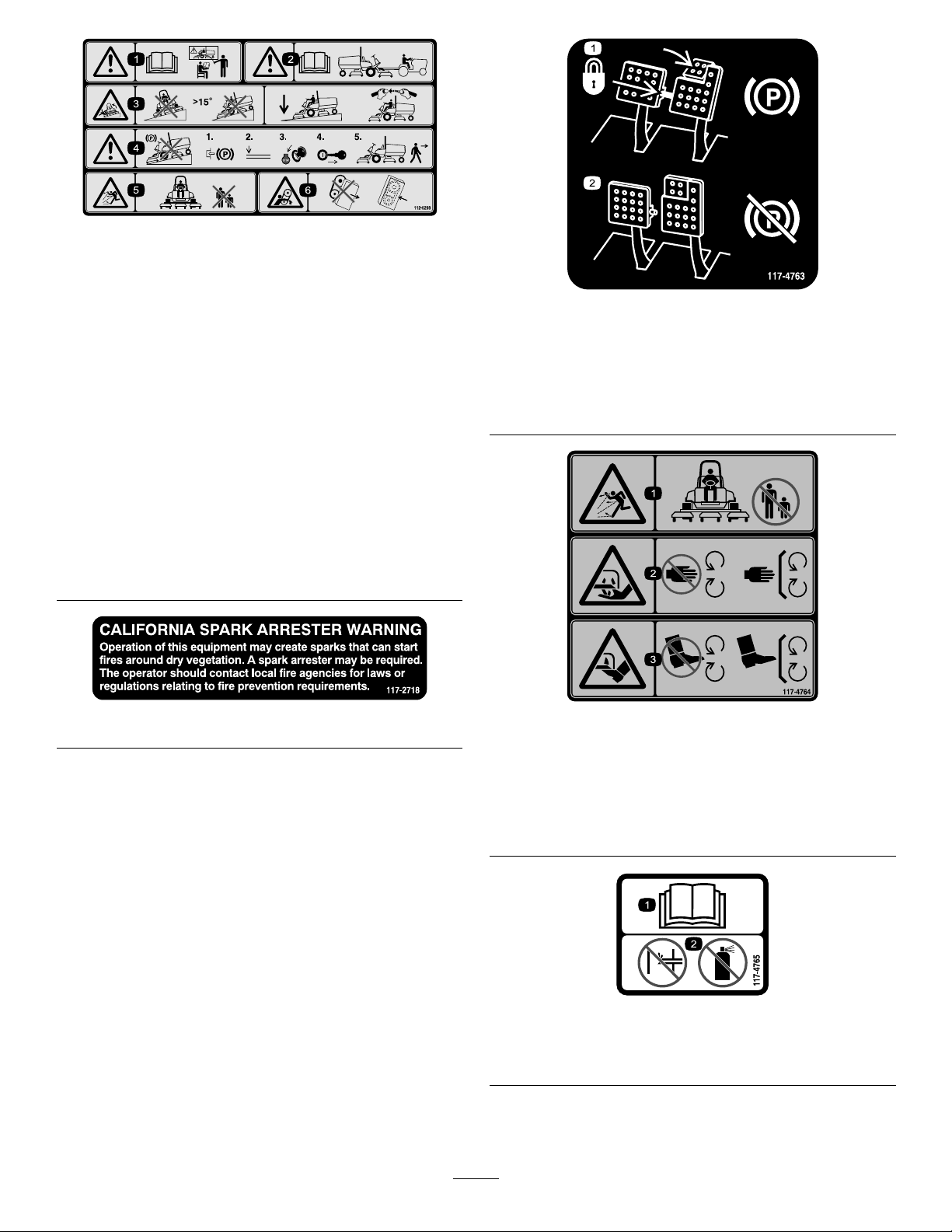
1.Toengagetheparking
brake,securethebrake
pedalswiththelockingpin,
presstheparkingbrake
pedalsandengagethetoe
pedal.
117-4763
2.Todisengagetheparking
brake,disengagethe
lockingpinandreleasethe
pedals.
117-2718
117-4764
1.Thrownobjecthazard—keepbystandersasafedistance
fromthemachine.
2.Cuttinghazardofhand,mowerblade—stayawayfrom
movingparts,keepallguardsandshieldsinplace.
3.Cuttinghazardoffoot,mowerblade—stayawayfrom
movingparts,keepallguardsandshieldsinplace.
117-4765
1.ReadtheOperator'sManual.
2.Donotusestartingaids.
6
Page 7
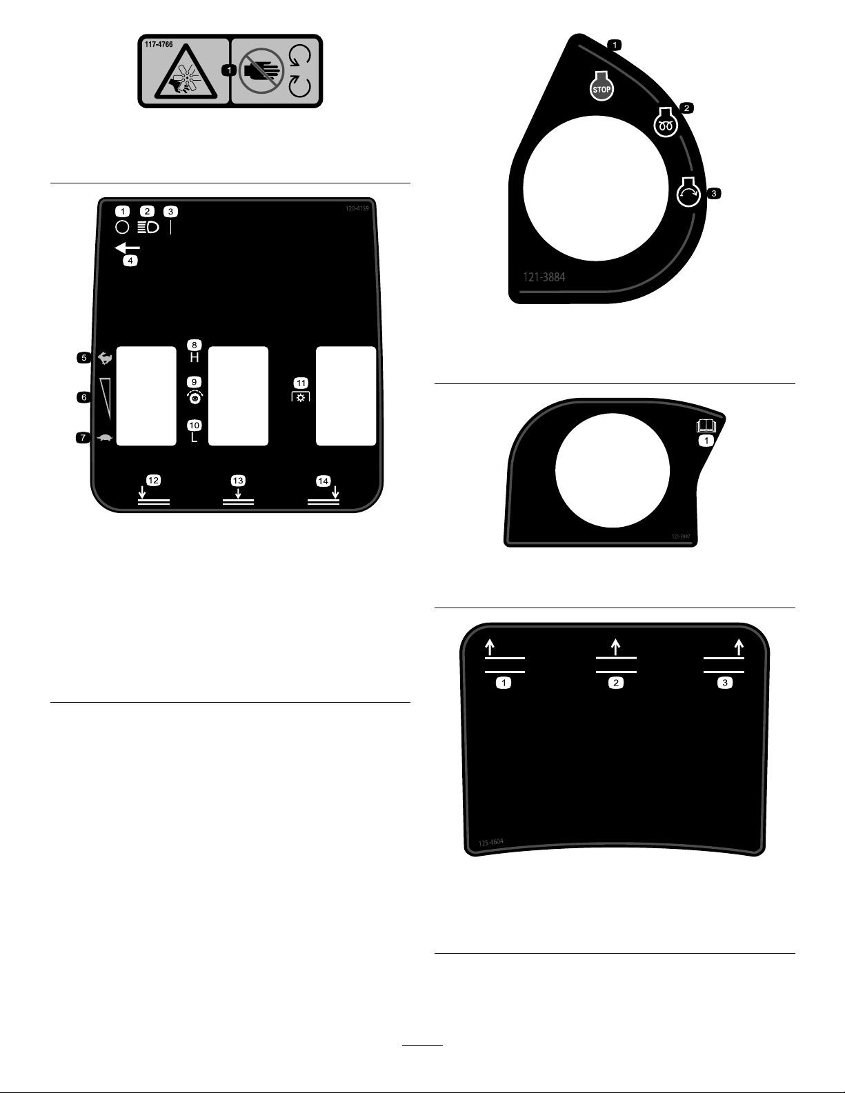
117-4766
1.Cutting/dismembermenthazard;fan—stayawayfrom
movingparts,keepallguardsandshieldsinplace.
121-3884
1.Engine—stop3.Engine—start
2.Engine—preheat
120-4159
Groundsmaster4700Shown
1.Off
2.Lights9.Tractiondrive
3.On
4.Lightswitchlocation
5.Fast
6.Variablespeedadjustment13.Lowercenterdeck
7.Slow
8.High
10.Low
11.Powertakeoff(PTO)
12.Lowerleftdeck
14.Lowerrightdeck
121-3887
1.ReadtheOperator’sManual.
125-4604
Groundsmaster4700Shown
1.Raiseleftdeck
2.Raisecenterdeck
3.Raiserightdeck
7
Page 8
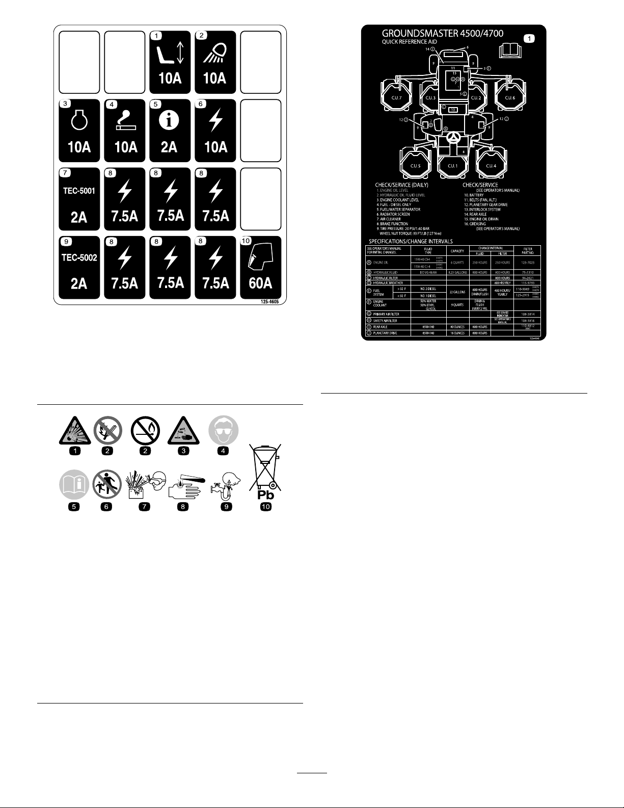
125-4605
1.Powerseat—10A6.Powersupplied—10A
2.Worklight—10A
3.Engine—10A8.Powersupplied—7.5A
4.Cigarettelighter—10A9.TEC-5002—2A
5.Infocenter—2A10.Cab—60A
7.TEC-5001—2A
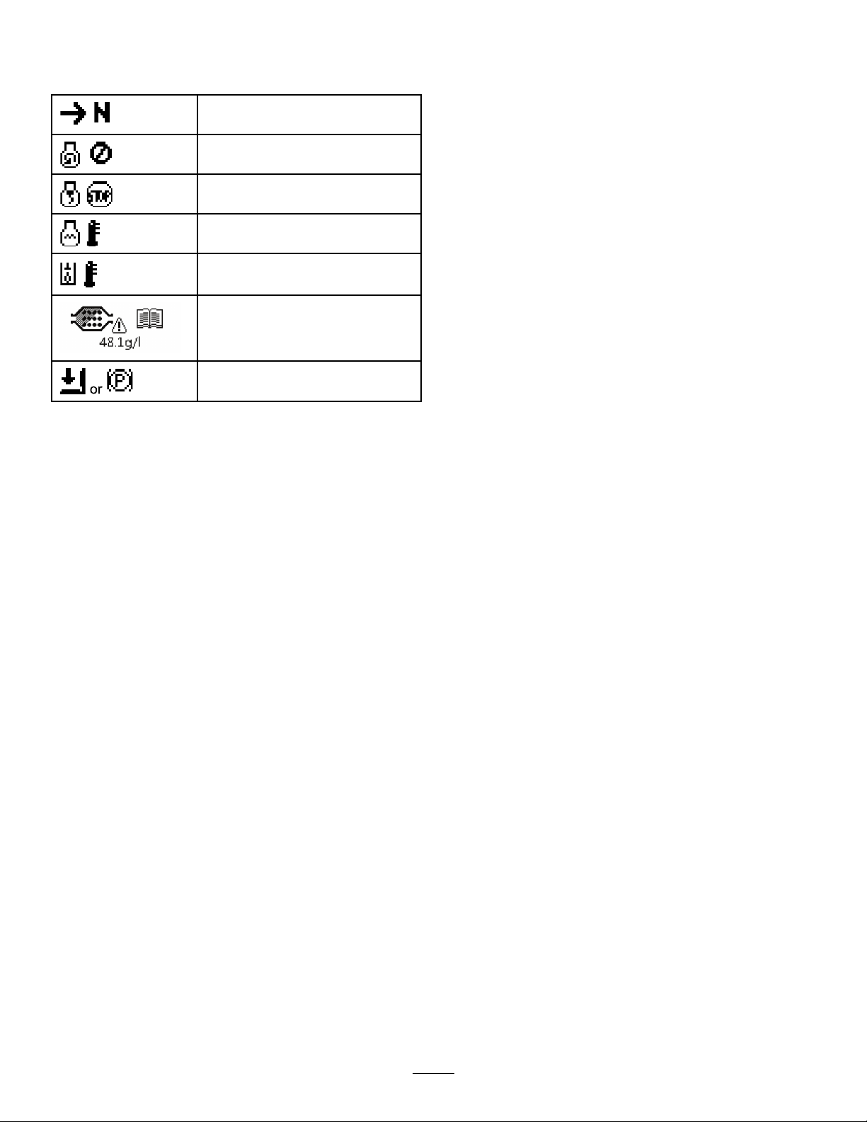
BatterySymbols
Someorallofthesesymbolsareonyourbattery .
125-4606
1.ReadtheOperator’sManualforinformationon
maintenance.
1.Explosionhazard
2.Nore,opename,or
smoking
3.Causticliquid/chemical
burnhazard
4.Weareyeprotection.9.Flusheyesimmediately
5.ReadtheOperator's
Manual.
6.Keepbystandersasafe
7.Weareyeprotection;
8.Batteryacidcancause
10.Containslead;donot
distancefromthebattery.
explosivegasescan
causeblindnessandother
injuries.
blindnessorsevereburns.
withwaterandgetmedical
helpfast.
discard
8
Page 9
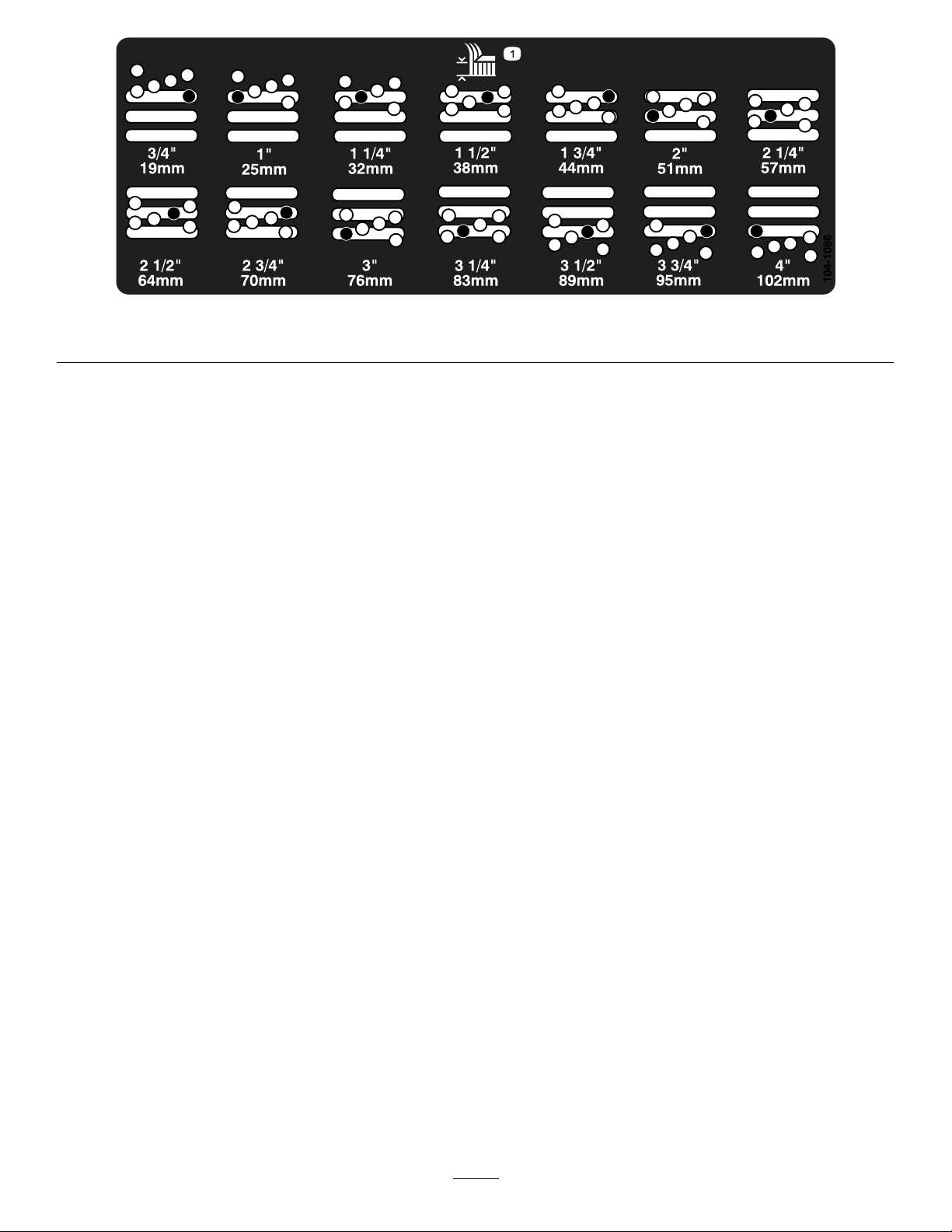
1.Heightofcut
104-1086
9
Page 10

Setup
LooseParts
Usethechartbelowtoverifythatallpartshavebeenshipped.
ProcedureDescription
Lockbracket1
Rivet2
1
2
3
4
Washer1
Screw(1/4x2inches)
Locknut(1/4inch)
Nopartsrequired
Nopartsrequired
Nopartsrequired
MediaandAdditionalParts
Description
WarningDecal6
Operator'sManual
EngineOperator'sManual
Qty.
Qty.
Installthehoodlatch(CE).
1
1
–
–
–
AfxtheCEwarningdecalsoverthecorresponding
Englishwarningdecals.
1
1
Readbeforeoperatingmachine
Readbeforeoperatingengine
Adjusttherollerscraper(optional).
Installthemulchingbafe(optional).
Preparethemachine.
Use
Use
PartsCatalog
OperatorTrainingMaterial
Note:Determinetheleftandrightsidesofthemachinefromthenormaloperatingposition.
1
1
Usetoreferencepartnumbers
Viewbeforeoperatingmachine
10
Page 11

1
G012628
1
2
G012629
1
2
G012630
1
G012631
1
2
3
InstallingtheHoodLatch(CE Only)
Partsneededforthisprocedure:
1Lockbracket
2Rivet
1Washer
1
Screw(1/4x2inches)
1
Locknut(1/4inch)
Procedure
1.Unhookthehoodlatchfromthehood-latchbracket.
2.Removethe2rivetssecuringthehood-latchbracketto
thehood(Figure3).Removethehood-latchbracket
fromthehood.
Figure4
1.CElockbracket
4.Alignthewasherswiththeholesontheinsideofthe
hood.
5.Rivetthebracketsandthewasherstothehood(Figure
4).
6.Hookthelatchontothehood-latchbracket(Figure5).
2.Boltandnutassembly
Figure5
1.Hoodlatch
Figure3
1.Hoodlatchbracket2.Rivets
3.Whilealigningthemountingholes,positionthe
CE-lockbracketandthehood-latchbracketontothe
hood.Thelockbracketmustbeagainstthehood
(Figure4).Donotremovetheboltandnutassembly
fromthelock-bracketarm.
7.Screwtheboltintotheotherarmofthehood-lock
brackettolockthelatchinposition(Figure6).Tighten
theboltbutdonottightenthenut.
Figure6
1.Bolt
2.Nut
3.Armofhood-lockbracket
11
Page 12
2
G011346
1
2
3
G011347
1
3
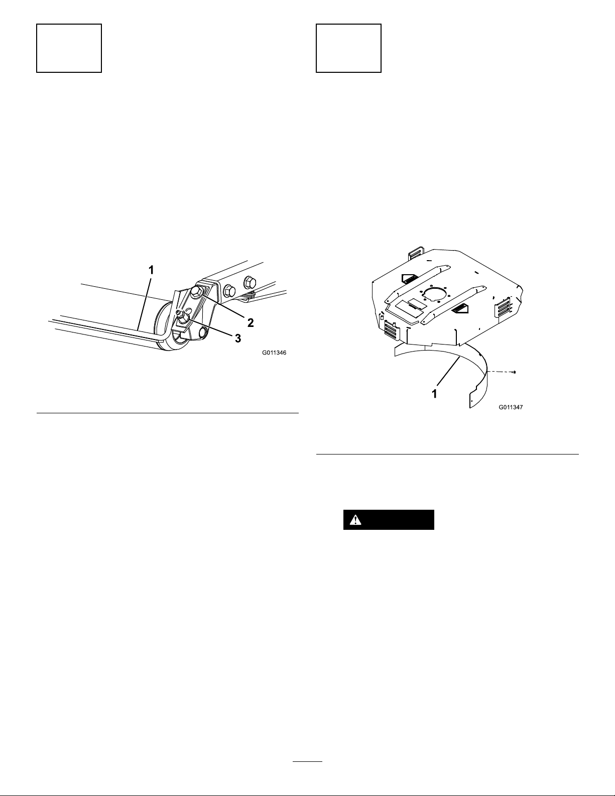
AdjustingtheRollerScraper
(Optional)
NoPartsRequired
Procedure
Theoptionalrearrollerscraperisdesignedtoworkbestwhen
thereisanevengapof0.5to1mm(0.020to0.040inch)
betweenthescraperandroller.
1.Loosenthegreasettingandthemountingscrew
(Figure7).
Figure7
InstallingtheMulchingBafe
(Optional)
NoPartsRequired
Procedure
1.Thoroughlycleandebrisfromthemountingholeson
therearwallandleftsidewallofthechamber.
2.Installthemulchingbafeintherearopeningand
secureitwith5ange-headbolts(Figure8).
1.Rollerscraper
2.Mountingscrew
2.Slidethescraperupordownuntilagapof0.5to1
mm(0.020to0.040inch)isachievedbetweentherod
andtheroller.
3.Securethegreasettingandscrewto41N-m(30ft-lb)
inanalternatingsequence.
3.Greasetting
Figure8
1.Mulchingbafe
3.Verifythatmulchingbafedoesnotinterferewith
thetipofthebladeanddoesnotprotrudeinsidethe
surfaceoftherearchamberwall.
DANGER
Usingthehigh-liftbladewiththemulching
bafecouldcausethebladetobreak,resulting
inpersonalinjuryordeath.
Donotusethehigh-liftbladewiththe
mulchingbafe.
12
Page 13
ProductOverview
4
PreparingtheMachine
NoPartsRequired
CheckingtheTirePressure
Checkthetirepressurebeforeuse;refertoCheckingtheTire
Pressure(page23).
Important:Maintainpressureinalltirestoensurea
goodquality-of-cutandpropermachineperformance.
Do not underinate the tir es.
CheckingtheFluidLevels
1.Checktherear-axlelubricantlevelbeforetheengineis
rststarted,refertoCheckingtheRearAxleGearBox
Lubricant(page44).
2.Checktheengine-oillevelbeforestartingtheengine;
refertoCheckingtheEngine-OilLevel(page36).
3.Checkthehydraulic-uidlevelbeforestartingthe
engine;refertoCheckingtheHydraulic-FluidLevel
(page47).
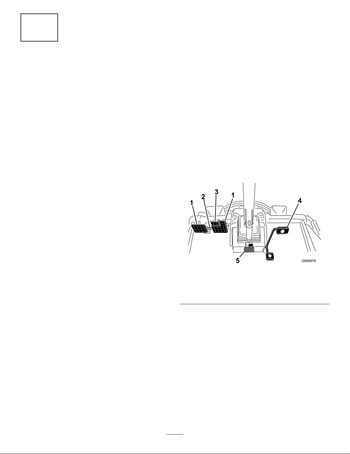
Controls
BrakePedals
2footpedals(Figure9)operateindividualwheelbrakesfor
turningassistanceandtoaidinobtainingbettersidehill
traction.
Pedal-LockingLatch
Thepedal-lockinglatch(Figure9)connectsthepedals
togethertoengagetheparkingbrake.
Parking-BrakePedal
Toengagetheparkingbrake,(Figure9)connectthepedals
togetherwiththepedal-lockinglatchandpushdownonthe
rightbrakepedalwhileengagingthetoepedal.T oreleasethe
parkingbrake,press1ofthebrakepedalsuntiltheparking
brakelatchretracts.
4.Checkthecoolingsystembeforestartingtheengine;
refertoCheckingtheCoolingSystem(page45).
GreasingtheMachine
Greasethemachinebeforeuse;refertoGreasingtheBearings
andBushings(page33).Failuretoproperlygreasethe
machineresultsinprematurefailureofcriticalparts.
Figure9
1.Brakepedal4.Tractionpedal
2.Pedal-lockinglatch5.Tilt-steeringpedal
3.Parking-brakepedal
TractionPedal
Thetractionpedal(Figure9)controlsforwardandreverse
operation.Pressthetopofthepedaltomoveforwardand
thebottomtomovebackward.
Tostop,reduceyourfootpressureonthetractionpedaland
allowittoreturntothecenterposition.
Tilt-SteeringPedal
Totiltthesteeringwheeltowardyou,pressthefootpedal
(Figure9)down,andpullthesteeringtowertowardyouto
themostcomfortablepositionandthenreleasethepedal.
13
Page 14
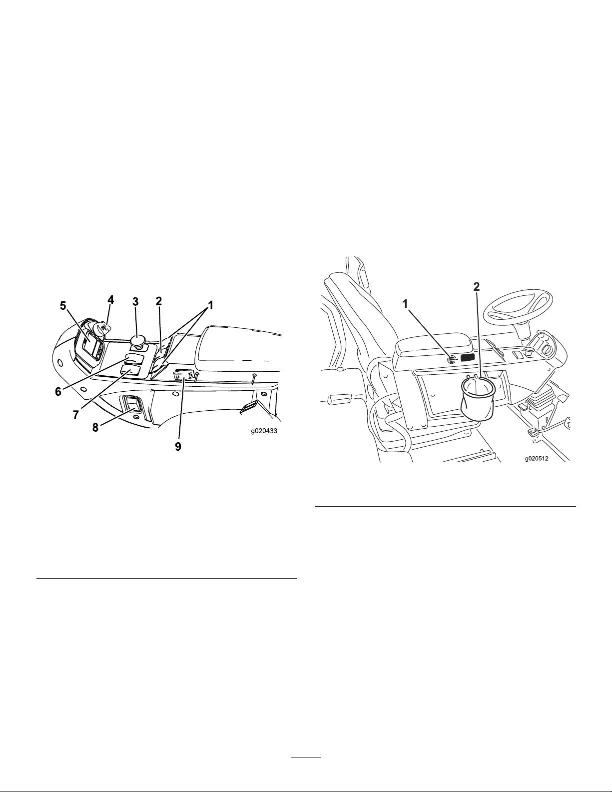
KeySwitch
g020512
Thekeyswitch(Figure10)has3positions:Off,On/Preheat,
andStart.
PTOSwitch
ThePTOswitch(Figure10)has2positions:Out(start)and
In(stop).PullthePTObuttonouttoengagethecutting
unitblades.Pushinthebuttontodisengagethecuttingunit
blades.
andbackwardtoraisethecuttingunits.Whenstartingthe
machine,withthecuttingunitsinthedownposition,pressthe
liftswitchdowntoallowthecuttingunitstooat,andmow .
Note:ThedecksdonotlowerwhileintheHispeedrange
andtheydonotraiseorloweriftheoperatorisoutoftheseat
whentheengineisrunning.Tolowerthedecksforservice,
rotatethekeyintheignitionswitchtotheONpositionwhile
sittingintheseat.
LightSwitch
High-LowSpeedControl
Theswitch(Figure10)allowsthespeedrangetoincrease
fortransportingthemachine.T oswitchbetweentheHigh
andLowspeedranges,raisethedecks,disengagethePTO ,
putthetractionpedalintotheNEUTRALposition,andmove
themachineataslowspeed.
Note:Thecuttingdecksdonotoperateand/orcannotbe
loweredfromthetransportpositionwhentheswitchisin
thehighrange.
Figure10
1.Liftswitches
(Groundsmaster4700
only)
2.Liftswitch(Groundsmaster
4500and4700)
3.PTOswitch
4.Keyswitch
5.InfoCenter
6.Hi-Lospeedcontrol
7.Engine-speedswitch
8.Lightswitch
9.Cruisecontrol
Presstheloweredgeoftheswitch(Figure10)toturnonthe
lights.Presstheupperedgeoftheswitchtoturnoffthelights.
PowerPoint
Usethepowerpoint(Figure11)topoweroptional12V
electricalaccessories.
Figure11
1.Powerpoint2.Bagholder
BagHolder
Usethebagholder(Figure11)forstorage.
Engine-SpeedSwitch
Theengine-speedswitch(Figure10)has2modestochange
theenginespeed.Taptheswitchtoincreaseordecreasethe
enginespeedin100rpmincrements.Holddowntheswitch
toautomaticallymovetoHighorLowidle,dependingon
whichendoftheswitchisdepressed.
LiftSwitches
Theliftswitches(Figure10)raiseandlowerthecutting
units.Presstheswitchesforwardtolowerthecuttingunits
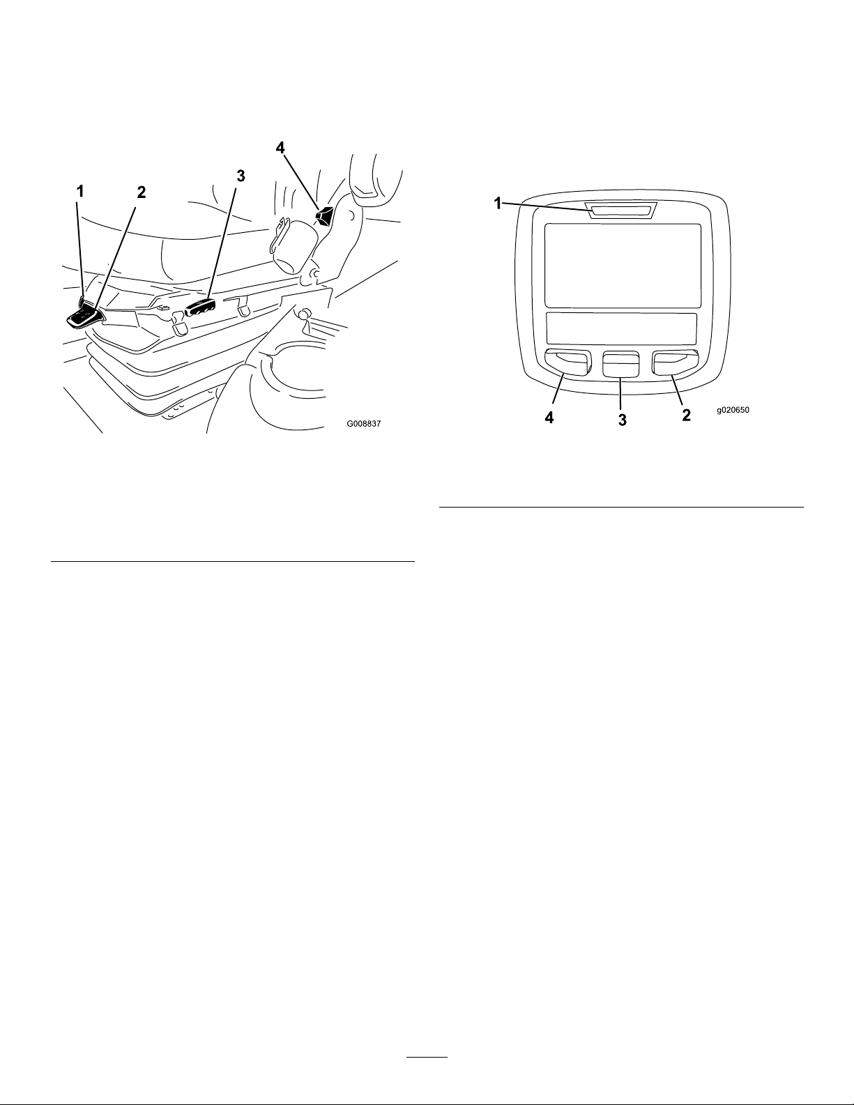
SeatAdjustments
SeatAdjustingLever
Pulloutonthelevertoslidetheseatforwardorrearward
(Figure12).
SeatArmRestAdjustingKnob
Rotatetheknobtoadjusttheseatarmrestangle.
SeatBackAdjustingLever
Movethelevertoadjusttheseatbackangle(Figure12).
14
Page 15
Weightgauge
1
g020650
2
3
4
TORO
UsingtheInfoCenterLCDDisplay
Indicateswhentheseatisadjustedtotheweightofthe
operator(Figure12).Heightadjustmentismadeby
positioningthesuspensionwithintherangeofthegreen
region.
Figure12
1.Weightgauge
2.Weight-adjustinglever5.Armrestadjustingknob
3.Seatadjustinglever
4.Seatbackadjustinglever
(notshown-locatedunder
armrest)
TheInfoCenterLCDdisplayshowsinformationaboutyour
machinesuchastheoperatingstatus,variousdiagnosticsand
otherinformationaboutthemachine(Figure13).Thereisa
splashscreenandmaininformationscreenoftheInfoCenter.
PressanyoftheInfoCenterbuttonsandthenselectthe
appropriatedirectionalarrowtoswitchbetweenthesplash
screenandthemaininformationscreen.
Figure13
1.Indicatorlight3.Middlebutton
2.Rightbutton
4.Leftbutton
•LeftButton,MenuAccess/BackButton—presstoaccess
theInfoCentermenus.Youcanuseittobackoutofany
menuyouarecurrentlyusing.
Weight-AdjustingLever
Adjustforyourweight(Figure12).Pulluptheleverto
increasetheairpressureandpushdowntodecreasetheair
pressure.Y ouattaintheproperadjustmentwhentheweight
gaugeisinthegreenregion.
•MiddleButton—presstoscrolldownmenus.
•RightButton—presstoopenamenuwherearightarrow
indicatesadditionalcontent.
•Beeper—activatedwhenloweringthedecksorfor
advisoriesandfaults.
Note:Thepurposeofeachbuttonmaychange
dependingonwhatisrequiredatthetime.Eachbuttonis
labeledwithanicondisplayingitscurrentfunction.
15
Page 16
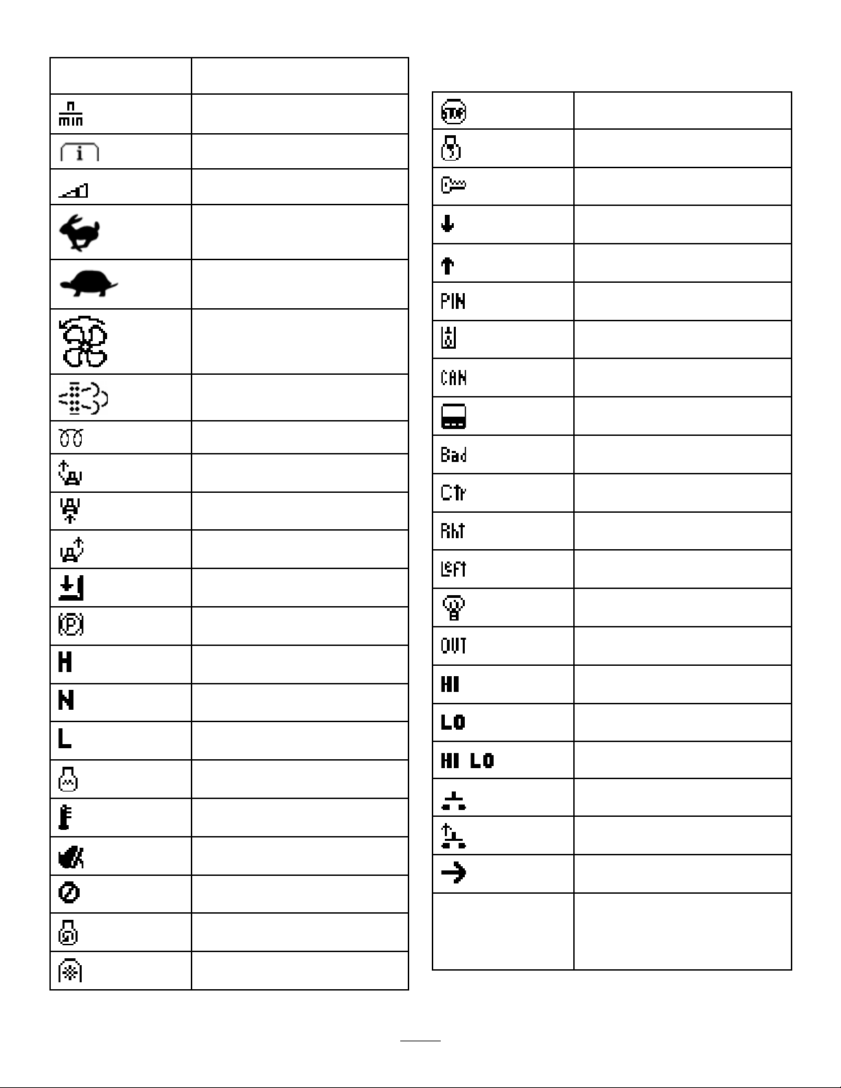
InfoCenterIconDescription
SERVICEDUE
Indicateswhenscheduledservice
shouldbeperformed
Thestatusoftheenginerpm.
InfoCenterIconDescription(cont'd.)
Stoptheengine.
Infoicon
Maximumtractionspeedsetting
Fast
Slow
Thefanisreversed.
Stationaryregenerationisrequired.
Theair-intakeheaterisactive
Raisetheleftdeck.
Raisethecenterdeck
Raisetherightdeck
Theoperatormustsitintheseat.
Theparkingbrakeison.
Therangeishigh.
Neutral
IdentiestherangeasLow
Coolanttemperature(°Cor°F)
Temperature(hot)
TractionorTractionPedal
Notallowed
Starttheengine.
ThePTOison.
Engine
Keyswitch
Cuttingunitsarelowering.
Cuttingunitsareraising.
PINpasscode
Hydraulicuidtemperature
CANbus
InfoCenter
Badorfailed
Center
Right
Left
Bulb
OutputofTECcontrollerorcontrol
wireinharness
Overtheallowedrange
Undertheallowedrange
Outofrange
/
Switch
Operatormustreleaseswitch.
Operatorshouldchangetoindicated
state.
Symbolsareoften
combinedtoform
sentences.Some
examplesareshown
below
16
Page 17
InfoCenterIconDescription(cont'd.)
Operatorshouldputmachinein
neutral.
Enginestartisdenied.
Engineshutdown.
Enginecoolantistoohot.
Hydraulicuidistoohot.
DPFashaccumulationnotication.
RefertoServicingtheDiesel
ParticulateFilter(DPF)inthe
maintenancesectionfordetails.
Sitdownorsetparkingbrake.
17
Page 18

UsingtheMenus
ToaccesstheInfoCentermenusystem,pressthemenuaccess
buttonwhileatthemainscreen.Thisbringsyoutothemain
menu.Refertothefollowingtablesforasynopsisofthe
optionsavailablefromthemenus:
MainMenu
MenuItemDescription
Faults
ServiceContainsinformationonthe
DiagnosticsListsvariousstatesthatthe
Settings
AboutListsthemodelnumber,serial
Service
MenuItemDescription
Hours
CountsListsthenumberofstarts,
Containsalistoftherecent
machinefaults.Referto
theServiceManualoryour
ToroDistributorformore
informationontheFaults
menuandtheinformation
containedthere.
machinesuchashoursofuse
andothersimilarnumbers.
machinecurrentlyhas.You
canusethistotroubleshoot
certainissuesasitquicklytells
youwhichmachinecontrols
areonandwhichareoff.
Allowsyoutocustomizeand
modifycongurationvariables
ontheInfoCenterdisplay.
number,andsoftwareversion
ofyourmachine.
Liststhetotalnumberofhours
thatthemachine,engineand
fanhavebeenon,aswell
asthenumberofhoursthe
machinehasbeentransported
andoverheated.
deckPTOcycles,andfan
reversalsthemachinehas
experienced.
Language
LCDBacklightControlsthebrightnessofthe
LCDContrastControlsthecontrastofthe
ProtectedMenusAllowsthemaintenance
ProtectSettings
AutoIdle
MowSpeedControlsthemaximumspeed
Trans.SpeedControlsthemaximumspeed
CounterbalanceControlstheamountof
Controlsthelanguageused
ontheInfoCenter*.
LCDdisplay.
LCDdisplay.
directortoaccessprotected
menusbyinputtinga
passcode.
Allowstheabilitytochange
thesettingsintheprotected
settings.
Controlstheamountoftime
allowedbeforeidlingthe
enginewhenthemachineis
notinuse.
whileinmow(lowrange).
whileintransport(highrange).
counterbalanceappliedbythe
decks.
*Only"operator-faced"textistranslated.Faults,Service,
andDiagnosticsscreensare"service-faced.”Titlesareinthe
selectedlanguage,butmenuitemsareinEnglish.
About
MenuItemDescription
Model
SNListstheserialnumberofthe
S/WRevListsthesoftwarerevisionof
Liststhemodelnumberofthe
machine.
machine.
themastercontroller .
Diagnostics
MenuItemDescription
LeftDeck
CenterDeck
RightDeck
TractionPedal
Traction
HI/LORange
PTO
EngineRun
Settings
MenuItemDescription
Units
RefertotheServiceManualor
yourToroDistributorformore
informationontheEngine
Runmenuandtheinformation
containedthere.
Controlstheunitsusedonthe
InfoCenter(EnglishorMetric).
18
Page 19

ProtectedMenus
Thereare5operatingcongurationsettingsthatare
adjustablewithintheSettingsMenuoftheInfoCenter:auto
idle,maximummowinggroundspeed,maximumtransport
groundspeed,SmartPower,anddeckcounterbalance.These
settingsareintheProtectedMenu.
2.Usetherightbuttontoincreasethemaxfullmow
speed(50%,75%,or100%).
3.Usethecenterbuttontodecreasethemaxfullmow
speed(50%,75%,or100%).
4.Presstheleftbuttontoexit.
AccessingtheProtectedMenuSettings
1.FromtheMainMenu,scrolldowntotheSettings
Menuandpresstherightbutton.
2.IntheSettingsMenu,scrolldowntotheProtected
Menuandpresstherightbutton.
3.Toenterthepasscode,usethecenterbuttontoset
therstdigitthenpresstherightbuttontomoveon
tothenextdigit.
4.Usethecenterbuttontosettheseconddigitthenpress
therightbuttontomoveontothenextdigit.
5.Usethecenterbuttontosetthethirddigitthenpress
therightbuttontomoveontothenextdigit.
6.Usethecenterbuttontosetthefourthdigitthenpress
therightbutton.
7.Pressthemiddlebuttontoenterthecode.
TheabilitytoviewandchangethesettingsintheProtected
Menucanbechanged.OncetheProtectedMenuhasbeen
accessed,scrolldowntoProtectSettings.Usingtheright
button,changingProtectSettingstoOFFwillallowthe
abilitytoviewandchangethesettingsintheProtectedMenu
withoutenteringthepasscode.ChangingProtectSettingsto
ONwillhidetheprotectedoptionsandwillrequireenteringa
passcodetochangethesettingintheProtectedMenu.After
thepasscodehasbeenset,thekeyswitchmustbeturnedoff
andbackontoenableandsavethisfeature.
SettingtheMaximumAllowedTransportSpeed
1.IntheSettingsMenu,scrolldowntoTransportSpeed
andpresstherightbutton.
2.Usetherightbuttontoincreasethemaxtransport
speed(50%,75%,or100%).
3.Usethecenterbuttontodecreasethemaxtransport
speed(50%,75%,or100%).
4.Presstheleftbuttontoexit.
TurningtheSmartPowerON/OFF
1.Inthesettingsmenu,scrolldowntoSmartPower.
2.PresstherightbuttontoswitchbetweenONandOFF.
3.Presstheleftbuttontoexit.
SettingtheCounterbalance
1.IntheSettingsMenu,scrolldowntoCounterBalance
andpresstherightbutton.
2.PresstherightbuttontoswitchbetweenLow,Med,
andHigh.
WhennishedwiththeProtectedMenu,presstheleftbutton
toexittotheMainMenu,thenpresstheleftbuttontoexit
totheRunMenu.
StationaryRegeneration
ViewingandChangingtheProtectedMenuSettings
1.IntheProtectedMenu,scrolldowntoProtectSettings.
2.Toviewandchangethesettingswithoutenteringa
passcode,usetherightbuttontochangetheProtect
SettingstoOFF.
3.Toviewandchangethesettingswithapasscode,use
theleftbuttontoselectON,setthepasscode,andturn
thekeyintheignitionswitchtotheOFFpositionand
thentotheONposition.
SettingtheAutoIdle
1.IntheSettingsMenu,scrolldowntoAutoIdle.
2.Presstherightbuttontochangetheauto-idletime
betweenOFF,8S,10S,15S,20S,and30S.
SettingtheMaximumAllowedMowSpeed
1.IntheSettingsMenu,scrolldowntoMowSpeedand
presstherightbutton.
IftheStationaryRegenerationiconappearsontheInfoCenter,
refertotheServiceManualorcontactyourToroDistributor
forthemaintenanceprocedure.
DPFAshLevel
TheDPFashlevelmaybecheckedbyenteringthePINas
describedinAccessingtheProtectedMenuSettings(page19)
andnavigatingtotheservicesection.
19
Page 20

Specications
Note:Specicationsanddesignaresubjecttochange
withoutnotice.
4500-D4700-D
Widthofcut2.8m(109inches)3.8m(150inches)
Overallwidth,
cuttingunitsdown
Overallwidth,
cuttingunitsup
(transport)
Overalllength370cm(145.8inches)370cm(145.8inches)
HeightwithROPS216cm(85inches)216cm(85inches)
Groundclearance15cm(6inches)15cm(6inches)
TrackWidth,front224cm(88.3inches)224cm(88.3inches)
TrackWidth,rear
Wheelbase
NetWeight(with
cuttingunitsand
nouids)
286cm(112.8inches)391cm(153.8inches)
224cm(88.25inches)224cm(88.25inches)
141cm(55.5inches)141cm(55.5inches)
171cm(67-1/2inches)171cm(67-1/2inches)
1894kg(4175lb)2,234kg(4,925lb)
CuttingDeck
Length
Width
Height
26.7cm(10–1/2inches)at3/4inchheightofcut
Weight
24.4cm(9.6inches)tocarriermount
34.9cm(13–3/4inches)at4inchheightofcut
86.4cm(34inches)
86.4cm(34inches)
88kg(195lb)
Attachments/Accessories
AselectionofToroapprovedattachmentsandaccessoriesisavailableforusewiththemachinetoenhanceandexpand
itscapabilities.ContactyourAuthorizedServiceDealerorDistributororgotowww.Toro.comforalistofallapproved
attachmentsandaccessories.
TobestprotectyourinvestmentandmaintainoptimalperformanceofyourToroequipment,countonTorogenuineparts.
Whenitcomestoreliability,Torodeliversreplacementpartsdesignedtotheexactengineeringspecicationofourequipment.
Forpeaceofmind,insistonT orogenuineparts.
20
Page 21

Operation
FuelSafety
Note:Determinetheleftandrightsidesofthemachine
fromthenormaloperatingposition.
BeforeOperation
BeforeOperationSafety
GeneralSafety
•Neverallowchildrenoruntrainedpeopletooperateor
servicethemachine.Localregulationsmayrestrictthe
ageoftheoperator.Theownerisresponsiblefortraining
alloperatorsandmechanics.
•Becomefamiliarwiththesafeoperationoftheequipment,
operatorcontrols,andsafetysigns.Knowhowtostop
themachineandenginequickly.
•Checkthatallsafetydevicesareattachedand
functioningproperly.Thisincludes,butisnotlimitedto,
operator-presencecontrols;safetyswitchesandshields;
therolloverprotectionsystem(ROPS);attachments;and
brakes.Donotoperatethemachineunlessallsafety
devicesareinpositionandfunctioningasintendedby
themanufacturer.
•Alwaysinspectthemachinetoensurethattheblades,
bladebolts,andcuttingassemblyarenotwornor
damaged.Replacewornordamagedbladesandboltsin
setstopreservebalance.
•Inspecttheareawhereyouwillusethemachineand
removeallobjectsthatthemachinecouldpotentially
throw .
•Evaluatetheterraintodeterminetheappropriate
equipmentandanyattachmentsoraccessoriesrequiredto
operatethemachineproperlyandsafely.
DANGER
Incertainconditions,fuelisextremelyammable
andhighlyexplosive.Areorexplosionfromfuel
canburnyouandothersandcandamageproperty.
•Fillthefueltankoutdoors,inanopenarea,when
theengineiscold.Wipeupanyfuelthatspills.
•Neverllthefueltankinsideanenclosedtrailer.
•Neversmokewhenhandlingfuel,andstayaway
fromanopenameorwherefuelfumesmaybe
ignitedbyaspark.
•Storefuelinanapprovedcontainerandkeepit
outofthereachofchildren.Neverbuymore
thana180-daysupplyoffuel.
•Donotoperatethemachinewithouttheentire
exhaustsysteminplaceandinproperworking
condition.
WARNING
Fuelisharmfulorfatalifswallowed.Long-term
exposuretovaporscancauseseriousinjuryand
illness.
•Avoidprolongedbreathingofvapors.
•Keepyourhandsandfaceawayfromthenozzle
andthefuel-tankopening.
•Keepfuelawayfromyoureyesandskin.
•Useonlyanapprovedfuelcontainer.
•Neverremovethefuelcaporaddfueltothefueltank
whiletheengineisrunning.
•Neverllcontainersinsideavehicleoronatruckor
trailerbedwithaplasticliner.Alwaysplacecontainerson
thegroundandawayfromyourvehiclebeforelling.
•Removetheequipmentfromthetruckortrailerandadd
fueltoitwhileitisontheground.Ifthisisnotpossible,
thenaddfuelusingaportablecontainerratherthanfrom
afuel-dispensernozzle.
•Keepthefuel-dispensernozzleincontactwiththerimof
thefueltankorcontaineropeningatalltimesuntilfueling
iscomplete.Donotuseanozzlelock-opendevice.
•Ifyouspillfuelonyourclothing,changeyourclothing
immediately.
•Fillthefueltankuntilthefuellevelis25mm(1inch)
belowthebottomofthellerneck.Donotoverllthe
fueltank.Replacethefuel-tankcapandtightenitsecurely .
21
Page 22

CheckingtheEngine-OilLevel
Beforeyoustarttheengineandusethemachine,check
theoillevelintheenginecrankcase;refertoCheckingthe
Engine-OilLevel(page36).
CheckingtheCoolingSystem
Beforeyoustarttheengineandusethemachine,checkthe
coolingsystem;refertoCheckingtheCoolingSystem(page
45).
CheckingtheHydraulic System
Beforeyoustarttheengineandusethemachine,checkthe
hydraulicsystem;refertoCheckingtheHydraulicLinesand
Hoses(page50).
FillingtheFuelTank
RecommendedFuel
•UseB5(biodieselcontentof5%)orlesserblendsincold
weather.
•Monitorseals,hoses,andgasketsincontactwithfuelas
theymaybedegradedovertime.
•Fuellterpluggingmaybeexpectedforatimeafter
convertingtobiodieselblends.
•Contactyourdistributorifyouwishformoreinformation
onbiodiesel.
Useonlyclean,freshdieselfuelwithultralow(<15
ppm)sulfurcontentmeetingASTMD975orEN590
specications.Theminimumcetaneratingshouldbe40.
Purchasefuelinquantitiesthatcanbeusedwithin180days
toensurefuelfreshness.
Fueltankcapacity:83L(22USgallons).
Usesummer-gradedieselfuel(No.2-D)attemperatures
above-7°C(20°F)andwinter-gradedieselfuel(No.1-Dor
No.1-D/2-Dblend)below-7°C(20°F).Usingwintergrade
fuelatlowertemperaturesprovideslowerashpointand
coldowcharacteristics,whicheasesstartingandreduces
fuellterplugging.
Usingsummergradefuelabove-7°C(20°F)contributes
towardlongerfuelpumplifeandincreasedpowercompared
towintergradefuel.
Important:Donotusekeroseneorgasolineinsteadof
dieselfuel.Failuretoobservethiscautionwilldamage
theengine.
BiodieselReady
Thismachinecanalsouseabiodieselblendedfuelofup
toB20(20%biodiesel,80%petrodiesel).Thepetrodiesel
portionmustbeultralowsulfur.Observethefollowing
precautions:
•Thebiodieselportionofthefuelmustmeetspecication
ASTMD6751orEN14214.
•TheblendedfuelcompositionshouldmeetASTMD975
orEN590.
•Paintedsurfacesmaybedamagedbybiodieselblends.
Figure14
Fillthetankwithdieselfueluntilthelevelreachesthebottom
ofthellerneck.
Note:Ifpossible,llthefueltankaftereachuse;thiswill
minimizepossiblebuildupofcondensationinsidethefuel
tank.
22
Page 23

CheckingtheTirePressure
ServiceInterval:Beforeeachuseordaily
Thecorrectairpressureinthetiresis138kPa(20psi).
Important:Maintaintherecommendedpressureinall
tirestoensureagoodqualityofcutandpropermachine
performance.Donotunder-inatethetires.
Checktheairpressureinallthetiresbeforeoperating
themachine.
Figure15
1.Lowerthecuttingdecktotheground,shutoffthe
engine,andremovethekeyfromtheignitionswitch.
2.Loosentheboltsecuringeachheight-of-cutbracket
totheheight-of-cutplate(frontandeachside);refer
toFigure16.
3.Beginningwithfrontadjustment,removethebolt.
Figure16
1.Height-of-cutbracket3.Spacer
2.Height-of-cutplate
CheckingtheTorqueofthe WheelNuts
ServiceInterval:Aftertherst8hours
Every200hours
WARNING
Failuretomaintainpropertorqueofthewheelnuts
couldresultinfailureorlossofwheelandmay
resultinpersonalinjury.
Torquethefrontandrearwheelnutsto115to136
N-m(85to100ft-lb)after1to4hoursofoperation
andagainafter8hoursofoperation.Torqueevery
200hoursthereafter.
Note:Frontwheelnutsare1/2-20UNF.Rearwheelnuts
areM12x1.6-6H(Metric).
AdjustingtheHeightofCut
Important:Thiscuttingdeckoftencutsapproximately
6mm(1/4inch)lowerthanareelcuttingunitwiththe
samebenchsetting.Itmaybenecessarytohavethese
rotarycuttingdeck’sbenchset6mm(1/4inch)above
thatofreelscuttinginthesamearea.
4.Whilesupportingthechamber,removethespacer
(Figure16).
5.Movethechambertothedesiredheightofcutand
installaspacerintothedesignatedheight-of-cuthole
andslot(Figure17).
Figure17
6.Positionthetappedplatein-linewiththespacer.
7.Installtheboltnger-tight.
8.Repeatsteps4through7foreachsideadjustment.
9.Torqueall3boltsto41N∙m(30ft-lb).Alwaystighten
thefrontboltrst.
Note:Adjustmentsofmorethan3.8cm(1-1/2
inches)mayrequiretemporaryassemblytoan
intermediateheighttopreventbinding(e.g.,changing
from3.1to7cm(1.25to2.75inches)heightofcut).
Important:Accesstotherearcuttingunitsisgreatly
improvedbyremovingthecuttingunitfromthetractor.
23
Page 24

CheckingtheInterlock Switches
Note:Makesurethatthedecksareloweredontoaclean
sectionofturforhardsurfacetoavoidthrowndustand
debris.
ServiceInterval:Beforeeachuseordaily
CAUTION
Ifsafetyinterlockswitchesaredisconnectedor
damaged,themachinecouldoperateunexpectedly
causingpersonalinjury.
•Donottamperwiththeinterlockswitches.
•Checktheoperationoftheinterlockswitches
dailyandreplaceanydamagedswitchesbefore
operatingthemachine.
Theinterlockswitchesaredesignedtostopthemachine
whentheoperatorgetsofftheseatwhenthetractionpedal
isdepressed.However,theoperatormaygetofftheseat
whiletheengineisrunningandthetractionpedalisin
theNEUTRALposition.Althoughtheenginecontinuesto
runifthePTOswitchisdisengagedandthetractionpedal
isreleased,itisstronglyrecommendedthattheenginebe
stoppedbeforerisingfromtheseat.
1.Parkthemachineonalevelsurface,lowerthecutting
unit,turnthekeyintheignitionswitchtotheOFF
position,andengagetheparkingbrake.
2.Pressthetractionpedal.Turnthekeyintheignition
switchtotheONposition.
Note:Iftheenginecranks,thereisamalfunctionin
theinterlocksystem.Correctthismalfunctionbefore
operatingthemachine.
Toverifythisstoppingtime,haveasecondpersonstandback
fromthedeckatleast6m(20ft)andwatchthebladeson1
ofthecuttingdecks.Havetheoperatorshutthecuttingdecks
downandrecordthetimeittakesforthebladestocometo
acompletestop.Ifthistimeisgreaterthan7seconds,the
brakingvalveneedsadjustment.CallyourToroDistributor
forassistanceinmakingthisadjustment.
SelectingaBlade
StandardCombinationSail
Thisbladewasdesignedtoprovideexcellentliftand
dispersioninalmostanycondition.Ifmoreorlessliftand
dischargevelocityisrequired,consideradifferentblade.
Attributes:Excellentliftanddispersioninmostconditions.
AngledSail
Thebladegenerallyperformsbestinlowerheightsof
cut—1.9to6.4cm(3/4to2-1/2inches).
Attributes:
•Dischargeremainsmoreevenatlowerheightsofcut.
•Dischargehaslesstendencytothrowleftandthusa
cleanerlookaroundbunkersandfairways.
•Lowerpowerrequirementatlowerheightsanddenseturf.
3.TurnthekeyintheignitionswitchtotheONposition,
risefromtheseat,andmovethePTOswitchtoON.
Note:ThePTOshouldnotengage.IfthePTO
engages,thereisamalfunctionintheinterlocksystem.
Correctthismalfunctionbeforeoperatingthemachine.
4.Engagetheparkingbrake,turnthekeyintheignition
switchtotheONposition,andmovethetractionpedal
outofNEUTRAL.
Note:TheInfoCenterdisplays"tractiondenied"and
themachineshouldnotmove.Ifthemachinedoes
move,thereisamalfunctionintheinterlocksystem.
Correctthismalfunctionbeforeoperatingthemachine.
CheckingtheBlade-Stopping Time
ServiceInterval:Beforeeachuseordaily
Thebladesofthecuttingdeckshouldcometoacomplete
stopinapproximately5secondsafteryoushutdownthe
cuttingdeckengagementswitch.
High-Lift,ParallelSail
Thebladegenerallyperformsbetterinthehigherheightsof
cut—7to10cm(2to4inches).
Attributes:
•Moreliftandhigherdischargevelocity.
•Sparseorlimpturfispickedupsignicantlyathigher
heightsofcut.
•Wetorstickyclippingsaredischargedmoreefciently
reducingcongestioninthedeck.
•Requiresmorehorsepowertorun.
•Tendstodischargefurtherleftandcantendtowindrow
atlowerheightsofcut.
DANGER
Usingthehigh-liftbladewiththemulchingbafe
couldcausethebladetobreak,resultinginpersonal
injuryordeath.
Donotusethehigh-liftbladewiththebafe.
24
Page 25

AtomicBlade
Thisbladewasdesignedtoprovideexcellentleafmulching.
Attributes:Excellentleafmulching
ChoosingAccessories
OptionalEquipmentCongurations
AngleSailBladeHigh-Lift,Parallel-Sail
GrassCutting:1.9to4.4
cm(0.75to1.75inch)
heightofcut
GrassCutting:5to6.4
cm(2.00to2.50inch)
heightofcut
GrassCutting:7to10
cm(2.75to4.00inch)
heightofcut
LeafMulchingRecommendedforuse
ProsEvendischargeatlower
ConsDoesnotliftthegrass
Recommendedinmost
applications
Recommendedforthick
orlushturf
Mayworkwellinlushturf
withthemulchingbafe
heightofcutCleaner
lookaroundbunkersand
fairwaysLowerpower
requirements
wellinhighheightof
cutapplicationsWet
orstickygrasshasa
tendencytobuildupin
thechamber,leading
topoorqualityofcut
andhigherpower
requirements
Blade(Donotusewith
themulchingbafe)
Mayworkwellinlightor
sparseturf
Recommendedforlight
orsparseturf
Recommendedinmost
applications
NotAllowedUsewithcombination
Moreliftandhigher
dischargevelocity
Sparseorlimpturfis
pickedupathighheight
ofcutWetorsticky
clippingsaredischarged
efciently
Requiresmorepowerto
runinsomeapplications
Tendstowindrowat
lowerheightofcutin
lushgrassDonotuse
withthemulchingbafe
MulchingBafeRollerScraper
Hasbeenshownto
improvedispersionand
aftercutperformance
onnortherngrassesthat
arecutatleast3times
perweekandlessthan
1/3ofthegrassblade
isremoved.Donot
usewiththehigh-lift,
parallel-sailblade
sailoranglesailblade
only
Mayimprovedispersion
andappearancein
certaingrasscutting
applicationsVerygood
forleafmulching
Grasswillbuildupinthe
chamberifattemptingto
removetoomuchgrass
withbafeinplace
Canbeusedanytime
thatrollersbuildupwith
grassorlargeatgrass
clumpsofgrassare
seen.Thescrapers
mayactuallyincrease
clumpingincertain
applications.
Reducesrollerbuildup
incertainapplications
25
Page 26

DuringOperation
DuringOperationSafety
GeneralSafety
•Theowner/usercanpreventandisresponsiblefor
accidentsthatmaycauseinjuriestopeople,ordamage
toproperty.
•Wearappropriateclothing,includingeyeprotection;
substantial,slip-resistantfootwear;andhearing
protection.Tiebacklonghair.Donotwearjewelry.
•EnsurethatalldrivesareintheNEUTRALposition,the
parkingbrakeisengaged,andyouareintheoperating
positionbeforeyoustarttheengine.
•Keepallbodyparts,includinghandsandfeet,awayfrom
allmovingparts.
•Donotoperatethemachinewhileill,tired,orunderthe
inuenceofalcoholordrugs.
•Keepthedirectionofthemowerdischargeawayfrom
peopleandpets.
•Donotmowinreverseunlessitisabsolutelynecessary.If
youmustmowinreverse,lookbehindanddownforsmall
childrenbeforeandwhilemovingthemachineinreverse.
Stayalertandstopthemachineifachildentersthearea.
•Useextremecarewhenapproachingblindcorners,
shrubs,trees,orotherobjectsthatmayblockyourview.
•Donotmowneardrop-offs,ditches,orembankments.
Themachinecouldsuddenlyrolloverifawheelgoesover
theedgeoriftheedgecavesin.
•Nevercarrypassengersonthemachine.
•Operatethemachineonlyingoodvisibilityand
appropriateweatherconditions.Donotoperatethe
machinewhenthereistheriskoflighting.
•Donotmowonwetgrass.Reducedtractioncouldcause
themachinetoslide.
•Neverraisethemowerdeckwiththebladesrunning.
•Stopthemachineandinspectthebladesafterstrikingan
objectorifthereisanabnormalvibrationinthemachine.
Makeallnecessaryrepairsbeforeresumingoperation.
•Stopthebladeswheneveryouarenotmowing,especially
whilecrossinglooseterrainsuchasgravel.
•Slowdownandusecautionwhenmakingturnsand
crossingroadsandsidewalkswiththemachine.Always
yieldtheright-of-way.
•Turnontheashingwarninglightsonthemachine
wheneveryoutravelonapublicroad,exceptwheresuch
useisprohibitedbylaw.
•Disengagethedrivetotheattachmentandshutoffthe
enginebeforeaddingfuelandadjustingtheheightofcut.
•Reducethethrottlesettingbeforestoppingtheengine
and,iftheenginehasafuel-shutoffvalve,shutoffthe
fuelwhenyouhavenishedoperatingthemachine.
•Neverrunanengineinanareawhereexhaustgasesare
enclosed.
•Neverleavearunningengineunattended.
•Beforeleavingtheoperatingposition,dothefollowing:
–Stopthemachineonlevelground.
–Disengagethepowertake-offandlowerthe
attachments.
–Settheparkingbrake.
–Shutofftheengineandremovethekey .
–Waitforallmovingpartstostop.
•Donotchangethegovernorsettingsonoroverspeed
theengine.Operatingtheengineatexcessivespeedmay
increasethepotentialforpersonalinjury.
•Donotusethemachineasatowingvehicle.
•UseaccessoriesandattachmentsapprovedbyTheToro®
Companyonly.
RolloverProtectionSystem(ROPS)
Safety
•DonotremovetheROPSfromthemachine.
•Ensurethattheseatbeltisattachedandthatyoucan
releaseitquicklyintheeventofanemergency.
•Alwayswearyourseatbelt.
•Checkcarefullyforoverheadclearances,suchasbranches,
doorways,andelectricalwires,beforedrivingthemachine
underthem.Donotcontactthem.
•KeeptheROPSinsafeoperatingconditionbythoroughly
inspectingitperiodicallyfordamageandkeepingallthe
mountingfastenerstight.
•ReplaceadamagedROPS.Donotrepairorreviseit.
•AnyalterationstoaROPSmustbeapprovedbyThe
Toro®Company.
SlopeSafety
•Slowdownthemachineanduseextracareonhillsides.
Travelintherecommendeddirectiononhillsides.Turf
conditionscanaffectthestabilityofthemachine.
•Avoidstarting,stopping,orturningthemachineona
slope.Ifthetireslosetraction,disengagetheblade(s)and
proceedslowlystraightdowntheslope.
•Donotturnthemachinesharply .Usecarewhenreversing
themachine.
•Whenoperatingthemachineonaslope,alwayskeepall
cuttingunitslowered.
•Avoidturningthemachineonslopes.Ifyoumustturn,
turnslowlyandgraduallydownhill,ifpossible.
•Useextracarewhileoperatingthemachinewith
attachments;theycanaffectthestabilityofthemachine.
Followtherecommendationsforusingthemachineona
slopeinthisOperator’ sManual.
26
Page 27

StartingandStoppingthe
UnderstandingtheOperating
Engine
Important:Bleedthefuelsystembeforestartingthe
engineiftheenginehasstoppedduetolackoffuel,or
youhaveperformedmaintenanceonthefuelsystem.
StartingtheEngine
1.Sitontheseat,keepyourfootoffthetractionpedalso
thatitisinNEUTRAL,andengagetheparkingbrake.
2.TurnthekeyintheignitionswitchtotheRUNposition.
Theglowindicatorwilllight.
3.Whentheglowindicatordims,turnthekeyinthe
ignitionswitchtotheSTARTposition.Releasethekey
immediatelywhentheenginestartsandallowitto
returntotheRUNposition.Adjusttheenginespeed.
Important:Donotrunthestartermotormore
than30secondsatatimeorprematurestarter
failuremayresult.Iftheenginefailstostartafter
30seconds,turnthekeyintheignitionswitch
totheOFFposition,recheckthecontrolsand
procedures,wait30additionalseconds,andrepeat
thestartingprocedure.
Whenthetemperatureislessthan-7°C(20°F),the
startermotorcanberunfor30secondsonthen60
secondsofffor2attempts.
CAUTION
Checkingthemachineforoilleaks,loose
parts,andothermalfunctionswhiletheengine
isrunningmaybringyouinclosecontactwith
hotormovingpartsofthemachine,causing
injury.
Shuttheengineoffandwaitforallmoving
partstostopbeforecheckingforoilleaks,
looseparts,andothermalfunctions.
CharacteristicsoftheMachine
Practicedrivingthemachinebecauseithasahydrostatic
transmissionanditscharacteristicsaredifferentthanmany
turfmaintenancemachines.Somepointstoconsider
whenoperatingthetractionunitandcuttingunitsarethe
transmission,enginespeed,loadonthecuttingbladesand
theimportanceofthebrakes.
WithToroSmartPower™,theoperatordoesnothave
tolistentotheenginespeedinheavyconditions.Smart
Powerpreventsboggingdowninheavyturfbyautomatically
controllingthemachinespeedandoptimizingcutting
performance.
Anothercharacteristictoconsideristheoperationofthe
pedalsthatareconnectedtothebrakes.Thebrakescanbe
usedtoassistinturningthemachine.However,usethem
carefully,especiallyonsoftorwetgrassbecausetheturf
maybetornaccidentally.Anotherbenetofthebrakesisto
maintaintraction.Forexample,insomeslopeconditions,the
uphillwheelslipsandlosestraction.Ifthissituationoccurs,
depresstheuphillturnpedalgraduallyandintermittentlyuntil
theuphillwheelstopsslipping,thus,increasingtractionon
thedownhillwheel.
Useextracarewhenoperatingthemachineonslopes.Make
surethattheseatlatchisproperlysecuredandtheseatbelt
isbuckled.Driveslowlyandavoidsharpturnsonslopesto
preventrollovers.Forsteeringcontrol,thecuttingunitmust
beloweredwhengoingdownhill.
Important:Allowenginetoidlefor5minutesbefore
shuttingitoffafterafullloadoperation.Thisallowsthe
turbochargertocooldownbeforeshuttingtheengine
off.Failuretodosomayleadtoturbo-chargertrouble.
Beforestoppingtheengine,disengageallcontrolsandset
theenginespeedtoSlow .SettingtheenginespeedtoSlow
reduceshighenginerpm,noise,andvibration.Turnthekeyin
theignitionswitchtotheOFFpositiontoshutofftheengine.
StoppingtheEngine
Important:Allowtheenginetoidlefor5minutesbefore
shuttingitoffafterafullloadoperation.Thisallowsthe
turbochargertocooldownbeforeshuttingtheengine
off.
Note:Lowerthecuttingunitstothegroundwhenever
machineisparked.Thisrelievesthehydraulicloadfromthe
system,preventswearonsystempartsandalsoprevents
accidentalloweringofthecuttingunits.
1.MovethePTOswitchtotheOFFposition.
2.Settheparkingbrake.
3.Returntheenginelowidle.
4.TurnthekeyintheignitionswitchtotheOFFposition
andremovethekey.
OperatingtheEngine-Cooling Fan
Theengine-cooling-fanswitchhas2positionsforcontrolling
theoperationofthefan.The2positionsareRandAUTO.
Thefanhastheabilitytoreversetoblowdebrisoffthe
rearscreen.Undernormaloperatingconditions,theswitch
shouldbeintheAUTOposition.InAuto,thefanspeedwill
becontrolledbythecoolantorhydraulic-oiltemperature
andwillautomaticallyreversetoblowdebrisofftherear
screen.Areversecycleisautomaticallyinitiatedwheneither
thecoolantorhydraulic-oiltemperaturereachesacertain
point.BypressingthefanswitchforwardintotheRposition,
thefanwillcompleteamanuallyinitiatedreversecycle.It
isrecommendedtoreversethefanwhentherearscreenis
cloggedorpriortoenteringtheshoporthestoragearea.
27
Page 28

OperatingTips
MowingWhenGrassIsDry
ResolvingAftercutAppearance
ReferenceAftercutAppearanceTroubleshootingGuide
availableatwww .Toro.com.
Moweitherinthelatemorningtoavoidthedew,which
causesgrassclumping,orinlateafternoontoavoidthe
damagecausedbydirectsunlightonthesensitive,freshly
mowedgrass.
SelectingtheProperHeightofCut
Removeapproximately25mm(1inch)ornomorethan1/3
ofthegrassbladewhencutting.Inexceptionallylushand
densegrass,youmayhavetoraisetheheightofcuttothe
nextsetting.
MowingatProperIntervals
Undermostnormalconditions,youwillneedtomow
approximatelyevery4to5days.Butremember,grassgrows
atdifferentratesatdifferenttimes.Thismeansthatinorder
tomaintainthesameheightofcut,whichisagoodpractice,
youwillneedtocutmorefrequentlyinearlyspring;asthe
grassgrowthrateslowsinmidsummer,cutonlyevery8to10
days.Ifyouareunabletomowforanextendedperioddue
toweatherconditionsorotherreasons,mowrstwiththe
heightofcutatahighlevel;thenmowagain2to3dayslater
withalower-heightsetting.
Transporting(Groundsmaster4700–D
Only)
Usethe2reartransportlatchesfortheoutercuttingunits
whentransportingoverlongdistances,roughterrain,orwhen
trailering.
CleaningandParkingtheMachineAfter
EachUse
Toensureoptimumperformance,cleantheundersideof
themowerhousingsaftereachuse.Ifresidueisallowedto
buildupinthemowerhousing,cuttingperformancewill
decline.
Note:Lowerthecuttingunitstothegroundwheneverthe
machineisparked.Thisrelievesthehydraulicloadfromthe
system,preventswearonsystemparts,andalsoprevents
accidentalloweringofthecuttingunits.
MowingwithSharpBlades
Asharpbladecutscleanlyandwithouttearingorshredding
thegrassbladeslikeadullblade.Tearingandshredding
causesthegrasstoturnbrownattheedgeswhichimpairs
growthandincreasessusceptibilitytodiseases.
ChangingMowingPatterns
Changemowingpatternsoftentominimizeafter-cut
appearanceissuesinducedbyrepetitiveoperationinonly1
direction.
AdjustingtheCounterbalance
Thecounterbalancesystemmaintainshydraulicbackpressure
onthedeckliftcylinders.Thiscounterbalancepressure
transferscuttingdeckweighttothemower'sdrivewheels
toimprovetraction.Thecounterbalancepressurehasbeen
factorysettoanoptimalbalanceofafter-cutappearanceand
tractioncapabilityinmostturfconditions.Decreasingthe
counterbalancesettingcanproduceamorestablecutting
deck,butcandecreasethetractioncapability.Increasingthe
counterbalancesettingcanincreasethetractioncapability,
butmayresultinafter-cutappearanceissues.Referencethe
ServiceManualforyourtractionunitforinstructionstoadjust
counterbalancepressure.
28
Page 29

AfterOperation
AfterOperationSafety
GeneralSafety
•Cleangrassanddebrisfromthecuttingunits,drives,
mufers,andenginetohelppreventres.Cleanupoil
orfuelspills.
•Shutoffthefuelwhilestoringortransportingthe
machine.
•Disengagethedrivetotheattachmentwheneveryouare
transportingornotusingthemachine.
•Allowtheenginetocoolbeforestoringthemachinein
anyenclosure.
•Neverstorethemachineorfuelcontainerwherethereis
anopename,spark,orpilotlight,suchasonawater
heateroronotherappliances.
TowingSafety
•Towonlywithamachinethathasahitchdesignedfor
towing.Donotattachtowedequipmentexceptatthe
hitchpoint.
•Followthemanufacturer’ srecommendationforweight
limitsfortowedequipmentandtowingonslopes.On
slopes,theweightofthetowedequipmentmaycauseloss
oftractionandlossofcontrol.
•Neverallowchildrenorothersinorontowedequipment.
•Travelslowlyandallowextradistancetostopwhen
towing.
Important:Donotpushortowthemachinefasterthan
3to4.8km/h(2to3mph)becauseinternaltransmission
damagemayoccur.Thebypassvalvemustbeopen
wheneveryoupushortowthemachine.
Important:Ifyoumustpushortowthemachinein
reverse,thecheckvalveinthefour-wheeldrivemanifold
mustalsobebypassed.T obypassthecheckvalve,
connectahoseassembly(PartNo.95-8843),2coupler
ttings(PartNo.95-0985),and2hydraulicttings
(PartNo.340-77)tothereverse-traction,pressuretest
port,locatedonthehydrostat,andontheportlocated
in-betweenportsM8andP2onthereartractionmanifold
whichislocatedtotheinsideofthefrontreartire.
1.Openthehoodandlocatethebypassvalves(Figure18)
onthetopofpump,behindthebattery/storageboxes.
2.Rotateeachvalve3turnscounter-clockwisetoopen
andallowoiltobypassinternally.Donotopen
morethan3turns.Becauseuidisbypassed,the
machinecanbeslowlymovedwithoutdamagingthe
transmission.
JackingPoints
Note:Alwaysusejackstands.Donotrelyonajackorhoist
toholdthemachine.
•Front—frame,ontheinsideofeachdrivetire.
•Rear—centeroftheaxle.
TieDowns
•UseproperlyratedDOTapprovedstrapsinfourcorners
totiedownmachine.
•Oneachsideoftheframebytheoperator’sseat.
•Ontherearbumper.
PushingorTowingthe Machine
Inanemergency,themachinecanbemovedforwardby
actuatingthebypassvalveinthevariabledisplacement
hydraulicpumpandpushingortowingthemachine.
Figure18
1.Bypassvalve(2)
3.Closethebypassvalvesbeforestartingtheengine.
Torqueto70N-m(52ft-lb)toclosethevalve.
HaulingtheMachine
•Usecarewhenloadingorunloadingthemachineintoa
traileroratruck.
•Usefull-widthrampsforloadingthemachineintoa
traileroratruck.
•Tiethemachinedownsecurelyusingstraps,chains,cable,
orropes.Bothfrontandrearstrapsshouldbedirected
downandoutwardfromthemachine.
29
Page 30

Maintenance
Note:Determinetheleftandrightsidesofthemachinefromthenormaloperatingposition.
Note:Downloadafreecopyoftheelectricalorhydraulicschematicbyvisitingwww .Toro.comandsearchingforyour
machinefromtheManualslinkonthehomepage.
RecommendedMaintenanceSchedule(s)
MaintenanceService
Interval
Aftertherst8hours
Aftertherst200hours
Beforeeachuseordaily
Every50hours
Every100hours
Every200hours
Every250hours
MaintenanceProcedure
•Torquethewheelnuts.
•Changetheplanetarygeardriveoil.
•Changetherearaxlelubricant.
•Changethehydrauliclters.
•Checkthetirepressure.
•Checktheinterlockswitches.
•Checkthebladestoppingtime.
•Checktheengine-oillevel.
•Drainwaterorothercontaminantsfromthewaterseparator.
•Drainwaterorothercontaminantsfromthefuellter/waterseparator.
•Checkthecoolingsystem.
•Removedebrisfromtheenginearea,oilcooler,andradiator.
•Checkthehydraulic-uidlevel.
•Inspectthehydrauliclinesandhosesforleaks,kinkedlines,loosemounting
supports,wear,loosettings,weatherdeterioration,andchemicaldeterioration.
•Greasethebearingsandbushings(oraftereverywashing).
•Checkthebatterycondition.
•Checktheconditionandtensionofthealternatorbelt.
•Torquethewheelnuts.
•Changetheengineoilandlter.
Every400hours
Every800hours
Every6,000hours
Beforestorage
•Servicetheaircleaner(earlieriftheaircleanerindicatorshowsred,andmore
frequentlyinextremelydirtyordustyconditions).
•Inspectthefuellinesandconnections.
•Replacethefuel-ltercanister.
•Replacetheenginefuellter.
•Checkforend-playintheplanetarydrives.
•Checktheplanetarygeardriveoillevel(Also,checkifexternalleakageisobserved).
•Checktherearaxlelubricantlevel.
•Checktherearaxlegearboxlubricant.
•Drainandcleanthefueltank.
•Changetheplanetarygeardriveoil(oryearly,whichevercomesrst).
•Changetherearaxlelubricant.
•Checktherearwheeltoe-in.
•Changethehydraulicuid.
•Changethehydrauliclters.
•Servicethedieseloxidationcatalyst(DOC)(orasrequired).
•Drainandcleanthefueltank.
•Checkthetirepressure.
•Checkallfasteners.
•Greaseoroilallgreasettingsandpivotpoints.
•Paintchippedsurfaces.
Yearly
•Inspectthefuellinesandconnections.
30
Page 31

Important:Refertoyour
Engine Operator's Man ual
maintenanceprocedures.
DailyMaintenanceChecklist
Duplicatethispageforroutineuse.
and
Cutting Unit Operator's Man ual
foradditional
Maintenance
CheckItem
Checkthe
safetyinterlock
operation.
Checkthebrake
operation.
Checktheengine
oilandfuellevel.
Checkthe
coolingsystem
uidlevel.
Drainthe
water/fuel
separator.
Checktheair
lterrestriction
indicator.
Checkthe
radiator,oil
cooler,and
screenfordebris.
Checkunusual
enginenoises.
Checkunusual
operatingnoises.
Checkthe
hydraulicsystem
oillevel.
Checkhydraulic
hosesfor
damage.
Checkforuid
leaks.
Checkthetire
pressure.
Checkthe
instrument
operation.
Lubricateall
greasettings.
Checkthe
height-of-cut
adjustment.
Touch-up
damagedpaint.
1
2
Fortheweekof:
Mon.Tues.Wed.Thurs.Fri.
Sat.Sun.
1.Checktheglowplugandinjectornozzlesifhardstarting,excesssmoke,orroughrunningisnoted.
2.Immediatelyaftereverywashing,regardlessoftheintervallisted.
31
Page 32

ServiceIntervalChart
Figure19
CAUTION
Ifyouleavethekeyintheignitionswitch,someonecouldaccidentlystarttheengineandseriouslyinjure
youorotherbystanders.
Removethekeyfromtheignitionswitchbeforeyouperformanymaintenance.
32
Page 33

Premaintenance
Lubrication
Procedures
GreasingtheBearingsand
RemovingtheHood
1.Releasethehoodlatches(Figure20)andpivotopen
thehood.
Figure20
1.Hoodlatch(2)
Bushings
ServiceInterval:Every50hours(oraftereverywashing).
Themachinehasgreasettingsthatmustbelubricated
regularlywithNo.2lithiumgrease.
Thegreasettinglocationsandquantitiesareasfollows:
•Brake-shaftpivotbearings(5)(Figure21)
Figure21
•Rearaxlepivotbushings(2)(Figure22)
2.Removethecotterpinssecuringtherearhoodbrackets
totheframepinsandliftoffthehood.
Figure22
33
Page 34

•Steeringcylinderballjoints(2)(Figure23)
•Cuttingunitspindle-shaftbearings(2percuttingunit)
(Figure25)
Note:Y oucanuseeithertting,whicheverismore
accessible.Pumpgreaseintothettinguntilasmall
amountappearsatbottomofthespindlehousing(under
thedeck).
Figure23
1.T opttingonkingpin
•Tie-rodballjoints(2)(Figure23)
•King-pinbushings(2)(Figure23).Thetopttingon
thekingpinshouldonlybelubricatedannually
(2pumps).
•Lift-armbushings(1perdeck)(Figure24)
Figure25
•Cuttingunitcarrier-armbushings(1percuttingunit)
(Figure25)
•Rearrollerbearings(2percuttingunit)(Figure26)
Figure26
Important:Makesurethatthegreasegroovein
eachrollermountalignswiththegreaseholeineach
endoftherollershaft.Tohelpalignthegrooveand
hole,thereisalsoanalignmentmarkon1endofthe
rollershaft.
Figure24
•Lift-cylinderbushings(2perdeck)(Figure24)
34
Page 35

EngineMaintenance
EngineSafety
Shutofftheenginebeforecheckingtheoiloraddingoilto
thecrankcase.
ServicingtheAirCleaner
ServiceInterval:Every400hours
Checktheair-cleanerbodyfordamagethatcouldcausean
airleak.Replaceitifitisdamaged.Checkthewholeintake
systemforleaks,damage,orloosehoseclamps.
Servicetheair-cleanerlteronlywhentheserviceindicator
(Figure27)requiresit.Changingtheairlterbeforeitis
necessaryonlyincreasesthechanceofdirtenteringtheengine
whenyouremovethelter.
Figure27
1.Air-cleanerindicator
Important:Besurethatthecoverisseatedcorrectly
andsealswiththeair-cleanerbody.
1.Replacetheaircleaner(Figure28).
Figure28
Note:Cleaningtheusedelementisnotrecommended
duetothepossibilityofdamagetotheltermedia.
Important:Neverattempttocleanthesafety
lter.Replacethesafetylterafterevery3primary
lterservices.
2.Resettheindicator(Figure27)ifitshowsred.
35
Page 36

ServicingtheEngineOil
CheckingtheEngine-OilLevel
ServiceInterval:Beforeeachuseordaily
Theengineisshippedwithoilinthecrankcase;however,the
oillevelmustbecheckedbeforeandaftertheengineisrst
started.
Thecrankcasecapacityisapproximately5.7L(6USqt)with
thelter.
Usehigh-qualityengineoilthatmeetsthefollowing
specications:
•APIClassicationLevelRequired:CJ-4orhigher.
•Preferredoil:SAE15W -40(above-18°C[0°F])
•Alternateoil:SAE10W-30or5W-30(alltemperatures)
Important:UsingnonCJ-4orhigheroilwillcause
DPFplugginganddamagetheengine.
Note:ToroPremiumEngineoilisavailablefromyour
distributorineither15W-40or10W-30viscosity .Seethe
PartsCatalogforpartnumbers.
Thebesttimetochecktheengineoiliswhentheengine
iscoolbeforeithasbeenstartedfortheday.Ifithas
alreadybeenrun,allowtheoiltodrainbackdowntothe
sumpforatleast10minutesbeforechecking.Iftheoil
levelisatorbelowtheADDmarkonthedipstick,addoil
tobringtheoilleveltotheFULLmark.Donotoverll.
IftheoillevelisbetweentheFULLandADDmarks,no
oiladditionisrequired.
Figure29
1.Parkthemachineonalevelsurface.
2.Checktheengine-oillevel(Figure29).
Note:Whenusingdifferentoil,drainalloldoilfrom
thecrankcasebeforeaddingnewoil.
36
Page 37

ChangingtheEngineOilandFilter
ServicingtheDiesel
ServiceInterval:Every250hours
1.Starttheengineandletitrun5minutestoallowthe
oiltowarmup.
2.Withthemachineparkedonalevelsurface,shutoff
theengine,removethekey,andwaitforallmoving
partstostopbeforeleavingtheoperatingposition.
3.Replacetheengineoilandlter(Figure30).
ParticulateFilter(DPF)
ServiceInterval:WheninstructedbytheInfocenter
TheDPFrequiresremovalandprofessionalcleaningafter
ithasaccumulatedover50g/Lofash.TheInfocenterwill
warmtheoperatorinphaseswhenthisDPFmaintenanceis
due.Therstwarningwilloccurwhentheashaccumulation
reaches48g/Landwillshowanadvisory(number179)on
theInfocenter.Thisadvisoryismeanttogiveyourservice
departmentnoticethatyourmachinewillsoonneedDPF
cleaningmaintenance.Ifyouwouldliketoknowthecurrent
levelofashinanyofyourToroTier4products,youcan
nditbygoingtotheServicemenuoftheInfocenterafter
enteringthePIN.Reference“UsingtheInfoCenterLCD
Display”formoreinformationonaccessingprotectedmenus.
Whentheashaccumulationreaches50g/L,youwillseea
enginefaultcomeupontheinfocenter(SPN3720,FMI16)
toalerttheoperatorthattheDPFneedscleaning.Alsoatthe
50g/Llevel,theenginewillde-rateitspowerto85%.Atthis
time,theDPFneedstoberemovedandreplacedwithaclean
DPF.AYanmardiagnostictoolwillneedtobeusedtoreset
theengineECUafteracleanDPFisinstalled.Talkwithyour
ToroDistributorandseeyourServiceManualformoredetails
ontheremovalandinstallationoftheDPF .
Figure30
4.Addoiltothecrankcase;refertoChangingtheEngine
OilandFilter(page37).
IftheDPFisnotcleanedatthe50g/Llevel,theenginewill
continuetorunatthede-rated85%powerleveluntiltheash
accumulationreaches60g/L.Whentheashlevelreaches60
g/L,theenginewillsendoutafault(SPN3720,FMI0)and
theenginewillde-rateto50%power.Atthistime,theDPF
isfullypluggedandneedstoberemovedandreplacedwitha
cleanDPF.AYanmardiagnostictoolwillneedtobeusedto
resettheengineECUafteracleanDPFisinstalled.
ForinformationonservicingtheDieselParticulateFilter
(DPF),refertotheServiceManualorcontactyourT oro
Distributor.
ServicingtheDieselOxidation Catalyst(DOC)
ServiceInterval:Every6,000hours(orasrequired).
ForinformationonservicingtheDieselParticulateFilter
(DPF),refertotheServiceManualorcontactyourT oro
Distributor.
37
Page 38

FuelSystem
ServicingtheWaterSeparator
Maintenance
DANGER
Undercertainconditions,dieselfuelandfuel
vaporsarehighlyammableandexplosive.Are
orexplosionfromfuelcanburnyouandothersand
cancausepropertydamage.
•Useafunneltollthefueltankoutdoors,inan
openarea,whentheengineisoffandiscold.
Wipeupanyfuelthatspills.
•Donotllthefueltankcompletelyfull.Add
fueltothefueltankuntilthelevelis6to13mm
(1/4to1/2inch)belowthebottomoftheller
neck.Thisemptyspaceinthetankallowsthe
fueltoexpand.
•Neversmokewhenhandlingfuel,andstayaway
fromanopenameorwherefuelfumesmaybe
ignitedbyaspark.
•Storefuelinaclean,safety-approvedcontainer
andkeepthecapinplace.
ServiceInterval:Beforeeachuseordaily—Drainwater
orothercontaminantsfromthefuel
lter/waterseparator.
Every400hours—Replacethefuel-ltercanister.
DrainingtheFuelTank
ServiceInterval:Every800hours—Drainandcleanthefuel
tank.
Beforestorage—Drainandcleanthefueltank.
Drainandcleanthetankiffuelsystembecomescontaminated
orifthemachinewillbestoredforanextendedperiodof
time.Usecleanfueltoushoutthetank.
InspectingtheFuelLinesand Connections
ServiceInterval:Every400hours
Yearly
Inspectthefuellinesandconnectionsfordeterioration,
damage,orlooseconnections.
Figure31
38
Page 39

ServicingtheFuelFilter
ElectricalSystem
ServiceInterval:Every400hours
1.Cleantheareaaroundthefuellterhead(Figure32).
Figure32
1.Fuel-lterhead
2.FuelFilter
Maintenance
ChargingandConnectingthe Battery
WARNING
CALIFORNIA
Proposition65Warning
Batteryposts,terminals,andrelated
accessoriescontainleadandleadcompounds,
chemicalsknowntotheStateofCalifornia
tocausecancerandreproductiveharm.
Washhandsafterhandling.
1.Unlatchandraisetheoperator'sconsolepanel(Figure
33).
2.Removethelterandcleanthelter-headmounting
surface(Figure32).
3.Lubricatetheltergasketwithcleanlubricatingengine
oil;refertotheEngineOperator'sManual.
4.Installthedryltercanister,byhand,untilthegasket
contactsthelterhead,thenrotateitanadditional
1/2turn.
5.Starttheengineandcheckforfuelleaksaroundthe
lterhead.
ServicingtheFuel-Pickup Tube
Thefuel-pickuptube,locatedinsidethefueltank,isequipped
withascreentohelppreventdebrisfromenteringthefuel
system.Removefuelpick-uptubeandcleanthescreenas
required.
1.Operator'sconsolepanel
Figure33
2.Latch
39
Page 40

DANGER
Batteryelectrolytecontainssulfuricacid
whichisadeadlypoisonandcausessevere
burns.
•Donotdrinkelectrolyteandavoidcontact
withskin,eyes,orclothing.Wearsafety
glassestoshieldyoureyesandrubber
glovestoprotectyourhands.
•Fillthebatterywherecleanwaterisalways
availableforushingtheskin.
2.Connecta3to4Abatterychargertothebatteryposts.
Chargethebatteryatarateof3to4Afor4to8hours.
3.Whenthebatteryischarged,disconnectthecharger
fromthepoweroutletandbatteryposts.
WARNING
CALIFORNIA
Proposition65Warning
Batteryposts,terminals,andrelated
accessoriescontainleadandleadcompounds,
chemicalsknowntotheStateofCalifornia
tocausecancerandreproductiveharm.
Washhandsafterhandling.
7.CoatbothbatteryconnectionswithGrafo112X
(skin-over)grease,PartNo.505-47,petroleumjelly ,or
lightgreasetopreventcorrosion.Slidetherubberboot
overthepositiveterminal.
8.Closetheconsolepanelandsecurethelatch.
WARNING
Chargingthebatteryproducesgassesthatcan
explode.
Neversmokenearthebatteryandkeepsparks
andamesawayfrombattery.
4.Installthepositivecable(red)tothepositive(+)
terminalandthenegativecable(black)tothenegative
(-)terminalofthebattery(Figure34).
5.Securethecablestothepostswithboltsandnuts.
Note:Makesurethatthepositive(+)terminalisall
ofthewayontothepostandthecableispositioned
snugtothebattery.Thecablemustnotcontactthe
batterycover.
6.Slidetherubberbootoverthepositiveterminalto
preventapossibleshortfromoccurring.
WARNING
Batteryterminalsormetaltoolscouldshort
againstmetalcomponents,causingsparks.
Sparkscancausethebatterygassesto
explode,resultinginpersonalinjury.
•Whenremovingorinstallingthebattery,
donotallowthebatteryterminalstotouch
anymetalpartsofthemachine.
•Donotallowmetaltoolstoshortbetween
thebatteryterminalsandmetalpartsof
themachine.
WARNING
Incorrectbatterycableroutingcoulddamage
themachineandcablescausingsparks.
Sparkscancausethebatterygassesto
explode,resultinginpersonalinjury.
•Alwaysdisconnectthenegative(black)
batterycablebeforedisconnectingthe
positive(red)cable.
Figure34
1.Positivebatterycable2.Negativebatterycable
•Alwaysconnectthepositive(red)battery
cablebeforeconnectingthenegative
(black)cable.
40
Page 41

ServicingtheBattery
ServiceInterval:Every50hours—Checkthebattery
condition.
Important:Beforeweldingonthemachine,disconnect
thenegative(black)cablefromthebatterytoprevent
damagetotheelectricalsystem.
Note:Keeptheterminalsandtheentirebatterycasecleanto
avoidslowdischarge.Tocleanthebattery,removeitfromthe
machineandwashtheentirecasewithasolutionofbaking
sodaandwater.Rinsewithclearwater.Coatthebatteryposts
andcableconnectorswithGrafo112X(skin-over)grease
(PartNo.505-47)orpetroleumjellytopreventcorrosion.
Fuses
Figure36
Figure35
Unhookthelatchandraiseoperator'sconsolepanel(Figure
36)toexposethefuses(Figure37).
1.Latch
1.Fuses
2.Operator'sconsolepanel
Figure37
41
Page 42

DriveSystem
g019500
Maintenance
CheckingthePlanetaryGear DriveOil
ServiceInterval:Every400hours
CheckingforEnd-Playinthe PlanetaryDrives
ServiceInterval:Every400hours
Thereshouldbenoend-playintheplanetarydrives/drive
wheels(i.e.,thewheelsshouldnotmovewhenyoupullor
pushtheminadirectionparalleltotheaxle).
1.Parkthemachineonalevelsurface,lowerthecuting
units,shutofftheengine,andremovethekeyfrom
theignitionswitch.
2.Chocktherearwheelsandraisethefrontofmachine,
supportingthefrontaxle/frameonjackstands.
DANGER
Amachineonajackmaybeunstableandslip
offofthejack,injuringanyonebeneathit.
•Donotstarttheenginewhilethemachine
isonajack.
•Alwaysremovethekeyfromtheignition
beforegettingoffofthemachine.
•Blockthetireswhenyouareraisingthe
machinewithajack.
•Supportthemachinewithjackstands.
3.Grasp1ofthefrontdrivewheelsandpush/pull
ittowardandawayfromthemachine,notingany
movement.
UsehighqualitySAE85W -140wt.gearlubeasareplacement.
1.Withmachineonlevelsurface,positionthewheelso
onecheckplug(Figure39)isatthe12o'clockposition
andtheotherisat3o'clockposition.
Figure39
1.Check/drainplug(2)
2.Removetheplugatthe3o’clockposition(Figure39).
Note:Theoillevelshouldbeatthebottomofthe
check-plughole.
3.Iftheoillevelislow,removetheplugatthe12o’clock
positionandaddoiluntilitbeginstoowoutthehole
atthe3o’clockposition.
Installbothplugs.
4.Repeatsteps1through4ontheoppositeplanetary
gearassembly.
ChangingthePlanetaryGear
Figure38
1.Frontdrivewheels
4.Repeatstep3fortheotherdrivewheel.
5.Ifeitherwheelmoves,contactyourToroDistributor
tohavetheplanetarydriverebuilt.
DriveOil
ServiceInterval:Aftertherst200hours
Every800hours(oryearly,whichevercomesrst).
UseahighqualitySAE85W -140wt.gearlubeasreplacement.
1.Positionthemachineonalevelsurfaceandpositiona
wheelsothat1ofthecheckplugsisatthelowest(6
o'clock)position(Figure40).
42
Page 43

1.Check/drainplug
g019743
Figure40
CheckingtheRearAxle Lubricant
ServiceInterval:Every400hours
TherearaxleisshippedfromthefactorylledwithSAE
85W-140wt.gearlube.Thecapacityis2.4L(80oz).Visually
inspectforleaksdaily.
1.Positionthemachineonalevelsurface.
2.Removeacheckplugfrom1endoftheaxle(Figure42)
andmakesurethatthelubricantisuptothebottom
ofthehole.
2.Placeadrainpanundertheplanetaryhub,removethe
plug,andallowtheoiltodrain.
3.Placeadrainpanunderthebrakehousing,removethe
drainplug,andallowtheoiltodrain(Figure41).
Figure41
1.Brakehousing2.Drainplug
3.Ifthelevelislow,removethellplug(Figure42)
andaddenoughlubricanttobringtheleveluptothe
bottomofthecheckplugholes.
Figure42
1.Checkplug
2.Fillplug
ChangingtheRearAxle Lubricant
4.Whenalloftheoilhasdrainedfrombothlocations,
installthepluginthebrakehousing.
5.Rotatethewheeluntiltheopenplughole,inthe
planetary,isatthetwelveo'clockposition.
6.Throughtheopenhole,slowlylltheplanetarywith
0.65L(22oz)ofhighqualitySAE85W -140wt.gear
lube.
Important:Iftheplanetaryllsbeforethe0.65L
(22oz)ofoilisadded,wait1hourorinstallthe
plugandmovethemachineapproximately3m(10
ft)todistributetheoilthroughthebrakesystem.
Then,removetheplugandaddtheremainingoil.
Installtheplug.
7.Repeattheprocedureontheoppositeplanetary/brake
assembly.
ServiceInterval:Aftertherst200hours
Every800hours
1.Positionthemachineonalevelsurface.
2.Cleantheareaaroundthe3drainplugs,1oneachend
and1inthecenter(Figure43).
Figure43
1.Drain-pluglocation
43
Page 44

3.Removethe3oil-levelcheckplugsandmainaxlevent
captoeaseindrainingoftheoil.
4.Removethedrainplugsandallowtheoiltodraininto
thepans.
5.Installtheplugs.
6.Removeacheckplugandllaxlewithapproximately
2.4L(80oz)of85W -140gearlubeoruntillubricant
isuptobottomofhole.
7.Installthecheckplug.
Figure45
CheckingtheRearAxleGear BoxLubricant
ServiceInterval:Every400hours
ThegearboxislledwithSAE85W -140gearlube.Checkthe
oillevelbeforetheengineisrststartedandevery400hours
thereafter.Thecapacityis0.5L(16oz).Visuallyinspectfor
leaksdaily.
1.Positionthemachineonalevelsurface.
2.Removethecheck/llplugfromtheleftsideofthe
gearbox(Figure44)andmakesurethatlubricantis
uptothebottomofthehole.Ifthelevelislow ,add
enoughlubricanttobringtheleveluptothebottom
ofthehole.
1.Frontoftractionunit3.Centertocenterdistance
2.1/8inchlessthanrearof
tire
2.Toadjust,removethecotterpinandnutfromeithertie
rodballjoint(Figure46).Removethetie-rodballjoint
fromtheaxle-casesupport.
Figure46
1.Tie-rodclamp2.Tie-rodballjoint
3.Loosentheclampsatbothendsofthetierods(Figure
46).
Figure44
1.Gearbox2.Check/llplug
CheckingtheRearWheel Toe-In
ServiceInterval:Every800hours/Yearly(whichevercomes
rst)
1.Measurethecenter-to-centerdistance(ataxleheight)
atthefrontandrearofthesteeringtires.Thefront
measurementmustbe3mm(1/8inch)lessthanthe
rearmeasurement(Figure45).
4.Rotatethedetachedballjointinwardoroutward1
completerevolutionandtightentheclampattheloose
endofthetierod.
5.Rotatetheentiretierodassemblythesamedirection
(inwardoroutward)1completerevolutionandtighten
theclampattheconnectedendofthetierod.
6.Installtheballjointintheaxle-casesupport,tighten
thenutnger-tight,andmeasurethetoe-in.
7.Repeatprocedureifnecessary.
8.Tightenthenutandinstallanewcotterpinwhenthe
adjustmentiscorrect.
44
Page 45

CoolingSystem
Maintenance
CoolingSystemSafety
CAUTION
Dischargeofhot,pressurizedcoolantortouchinga
hotradiatorandsurroundingpartscancausesevere
burns.
•Donotremovetheradiatorcapwhentheengine
ishot.Alwaysallowtheenginetocoolatleast15
minutesoruntiltheradiatorcapiscoolenough
totouchwithoutburningyourhandbefore
removingtheradiatorcap.
•Donottouchtheradiatorandsurroundingparts
thatarehot.
DANGER
Swallowingenginecoolantcancausepoisoning.
•Donotswallowenginecoolant.
•Keepoutofreachfromchildrenandpets.
CheckingtheCoolingSystem
ServiceInterval:Beforeeachuseordaily
Checklevelofcoolantatthebeginningofeachday.The
capacityofthesystemis8.5L(9USqt).
1.Carefullyremovetheradiatorcap.
CAUTION
Iftheenginehasbeenrunning,the
pressurized,hotcoolantcanescapeandcause
burns.
•Donotopentheradiatorcapwhenthe
engineisrunning.
•Usearagwhenopeningtheradiatorcap,
andopenthecapslowlytoallowsteamto
escape.
Figure47
1.Expansiontank
2.Checkthecoolantlevelintheradiator.Theradiator
shouldbelledtothetopofthellerneckandthe
expansiontanklledtotheFULLmark(Figure47).
3.Ifthecoolantislow ,adda50/50mixtureofwaterand
ethyleneglycolantifreeze.Donotusewateronlyor
alcohol/methanolbasecoolants.
4.Installtheradiatorcapandexpansion-tankcap.
CleaningtheCoolingSystem
ServiceInterval:Beforeeachuseordaily—Removedebris
fromtheenginearea,oilcooler,and
radiator.
Cleanthemmorefrequentlyindirtyconditions.
Thismachineisequippedwithahydraulicallydrivenfandrive
systemthatautomatically(ormanually)reversestoreduceoil
cooler/radiatorandscreendebrisbuild-up.Whilethisfeature
canhelpreducethetimerequiredtocleanoilcooler/radiator,
itdoesnoteliminatetheneedforroutinecleaning.Periodic
cleaningandinspectionoftheradiator/coolerisstillrequired.
1.Unlatchandswingopentherearscreen(Figure48).
Note:Toremovethescreen,liftoffthehingepins.
2.Cleanthescreenthoroughlyofalldebris.
45
Page 46

Figure48
1.Rear-screenlatch
3.Thoroughlycleanbothsidesoftheoilcoolerandthe
radiator(Figure49)withcompressedair.Startfrom
thefrontandblowthedebrisouttowardtheback.
Thencleanfromthebacksideandblowtowardthe
front.Repeatprocedureseveraltimesuntilyouremove
allchaffanddebris.
BrakeMaintenance
AdjustingtheServiceBrakes
Adjusttheservicebrakeswhenthereismorethan25mm(1
inch)offreetravelofthebrakepedalorwhenthebrakes
donotworkeffectively.Freetravelisthedistancethebrake
pedalmovesbeforebrakingresistanceisfelt.
1.Disengagethelockinglatchfromthebrakepedalsso
thatbothpedalsworkindependentlyofeachother.
2.Toreducefreetravelofthebrakepedals,tightenthe
brakes:
A.Loosenthefrontnutonthethreadedendofthe
brakecable(Figure50).
Figure49
1.Oilcooler/radiator
Important:Cleaningtheoilcooler/radiatorwith
waterpromotesprematurecorrosiondamageto
componentsandcompactsdebris.
Figure50
1.Brakecable
B.Tightentherearnuttomovethecablebackward
untilthebrakepedalshave13to25mm(1/2to
1inch)offreetravel.
C.Tightenthefrontnutsafterthebrakesareadjusted
correctly.
4.Closetherearscreenandsecureitwiththelatch.
46
Page 47

BeltMaintenance
g020537
1
2
ServicingtheAlternatorBelt
HydraulicSystem
Maintenance
ServiceInterval:Every100hours
1.Checkthetensionofthealternatorbeltbydepressing
itmidwaybetweenthealternatorandthecrankshaft
pulleyswith4.5kg(10lb)offorce.
Note:Thebeltshoulddeect10mm(3/8inch).Ifthe
deectionisincorrect,proceedtostep2.Ifcorrect,
continueoperation.
2.Loosenthealternator-mountingbolts(Figure51).
3.Increaseordecreasethealternatorbelttensionand
tightenthebolts.Checkthedeectionofthebeltagain
toensurethatthetensioniscorrect.
HydraulicSystemSafety
WARNING
Hydraulicuidescapingunderpressurecan
penetrateskinandcauseinjury.
•Ensurethatallhydraulic-uidhosesand
linesareingoodconditionandallhydraulic
connectionsandttingsaretightbefore
applyingpressuretothehydraulicsystem.
•Keepyourbodyandhandsawayfrompinhole
leaksornozzlesthatejecthigh-pressure
hydraulicuid.
•Usecardboardorpapertondhydraulicleaks.
•Safelyrelieveallpressureinthehydraulicsystem
beforeperforminganyworkonthehydraulic
system.
•Seekimmediatemedicalattentionifuidis
injectedintotheskin.
1.Mountingbolt2.Alternator
Figure51
CheckingtheHydraulic-Fluid Level
ServiceInterval:Beforeeachuseordaily
Thereservoirislledatthefactorywithapproximately28.4
L(7.50USgallons)ofhigh-qualityhydraulicuid.Checkthe
levelofthehydraulicuidbeforetheengineisrststarted
anddailythereafter.Therecommendedreplacementuid
isasfollows:
ToroPremiumAllSeasonHydraulicFluid(Availablein19
L(5USgallon)pailsor208L(55USgallon)drums.Seethe
PartsCatalogoryourToroDistributorforpartnumbers.)
Alternateuids:IftheTorouidisnotavailable,otheruids
maybeusedprovidedtheymeetallthefollowingmaterial
propertiesandindustryspecications.W edonotrecommend
theuseofsyntheticuid.Consultwithyourlubricant
distributortoidentifyasatisfactoryproduct.
Note:Torowillnotassumeresponsibilityfordamage
causedbyimpropersubstitutions,souseonlyproducts
fromreputablemanufacturerswhowillstandbehindtheir
recommendation.
47
Page 48

HighViscosityIndex/LowPourPoint
Anti-wearHydraulicFluid,ISOVG46
MaterialProperties:
Viscosity,ASTMD445cSt@40°C(104°F)
ViscosityIndexASTM
D2270
PourPoint,ASTMD97-37°Cto-45°C(-34°Fto
IndustrySpecications:VickersI-286-S(Quality
Important:TheISOVG46Multigradeuidhasbeen
foundtoofferoptimalperformanceinawiderangeof
temperatureconditions.Foroperationinconsistently
highambienttemperatures,65°F(18°C)to120°F
(49°C),ISOVG68hydraulicuidmayofferimproved
performance.
PremiumBiodegradableHydraulicFluid-MobilEAL
EnviroSyn46H
Important:MobilEALEnviroSyn46Histheonly
syntheticbiodegradableuidapprovedbyT oro.This
uidiscompatiblewiththeelastomersusedinToro
hydraulicsystemsandissuitableforawide-range
oftemperatureconditions.Thisuidiscompatible
withconventionalmineraloils,butformaximum
biodegradabilityandperformancethehydraulicsystem
shouldbethoroughlyushedofconventionaluid.The
uidisavailablein19L(5USgallon)containersor208
L(55USgallon)drumsfromyourMobilDistributor.
44to48
cSt@100°C(212°F)
7.9to9.1
140to160
-49°F)
Level),VickersM-2950-S
(QualityLevel),Denison
HF-0
Important:Manyhydraulicuidsarealmostcolorless,
makingitdifculttospotleaks.Areddyeadditivefor
thehydraulicsystemuidisavailablein20ml(2/3oz)
bottles.1bottleissufcientfor15to22L(4to6US
gallons)ofhydraulicuid.Orderpartno.44-2500from
yourToroDistributor.
1.Positionthemachineonalevelsurface,lowerthe
cuttingunits,shutofftheengine,andremovethekey.
2.Checkthehydraulic-uidlevel(Figure52).
Figure52
48
Page 49

ChangingtheHydraulicFluid
ReplacingtheHydraulicFilters
ServiceInterval:Every800hours
Iftheuidbecomescontaminated,contactyour
ToroDistributorbecausethesystemmustbeushed.
Contaminateduidlooksmilkyorblackwhencomparedto
cleanoil.
1.TurnthekeyintheignitionswitchtotheOFFposition
andraisethehood.
2.Disconnectthecasereturnlinefromthebottomofthe
reservoirandletthehydraulicuidowintoalarge
drainpan.
3.Installthehosewhenthehydraulicuidstopsdraining.
4.Fillthereservoirwithapproximately28.4L(7.50
USgallons)ofhydraulicuid;refertoCheckingthe
Hydraulic-FluidLevel(page47).
Important:Useonlythehydraulicuids
specied.Otheruidscouldcausesystem
damage.
5.Installthereservoircap.
6.TurnthekeyintheignitionswitchtotheONposition
tostarttheengine,useallofthehydrauliccontrolsto
distributehydraulicuidthroughoutthesystem,and
checkforleaks.
ServiceInterval:Aftertherst200hours
Every800hours
UseT ororeplacementltersPartNo.94-2621fortherear
(cuttingunit)ofthemachineandPartNo.75-1310forthe
front(charge)ofthemachine.
Important:Useofanyotherltermayvoidthewarranty
onsomecomponents.
1.Positionthemachineonalevelsurface,lowerthe
cuttingunits,shutofftheengine,engagetheparking
brakes,andremovetheignitionkey.
2.Replacethehydrauliclters(Figure53).
7.TurnthekeyintheignitionswitchtotheOFFposition.
8.Checktheuidlevelandaddenoughtoraiselevelthe
leveltotheFULLmarkonthedipstick.Donotoverll.
Figure53
3.Starttheengineandletitrunforabout2minutesto
purgeairfromthesystem.Shutofftheengineand
checkforleaks.
49
Page 50

CheckingtheHydraulicLines andHoses
ServiceInterval:Beforeeachuseordaily
CuttingDeck Maintenance
Inspectthehydrauliclinesandhosesforleaks,kinkedlines,
loosemountingsupports,wear,loosettings,weather
deterioration,andchemicaldeterioration.Makeallnecessary
repairsbeforeoperatingthemachine.
WARNING
Hydraulicuidescapingunderpressurecan
penetrateskinandcauseinjury.
•Makesurethatallhydraulic-uidhosesand
linesareingoodconditionandallhydraulic
connectionsandttingsaretightbefore
applyingpressuretothehydraulicsystem.
•Keepyourbodyandhandsawayfrompin
holeleaksornozzlesthatejecthigh-pressure
hydraulicuid.
•Usecardboardorpapertondhydraulicleaks.
•Safelyrelieveallpressureinthehydraulicsystem
beforeperforminganyworkonthehydraulic
system.
•Seekimmediatemedicalattentionifuidis
injectedintotheskin.
SeparatingtheCuttingDecks fromtheTractionUnit
1.Positionthemachineonalevelsurface,lowerthe
cuttingdeckstotheoor,turnthekeyintheignition
switchtotheOFFposition,andengagetheparking
brake.
2.Disconnectandremovethehydraulicmotorfrom
thedeck(Figure54).Coverthetopofthespindleto
preventcontamination.
Figure54
1.Motor-mountingscrews
3.Removethelynchpinorretainingnut(Groundsmater
4700only)securingthedeck-carrierframetothe
lift-armpivotpin(Figure55).
Figure55
1.Lynchpin
4.Rollthecuttingdeckawayfromthetractionunit.
2.Lift-armpivotpin
50
Page 51

MountingtheCuttingDecksto
G011353
6:00
12:00
9:00
3:00
theTractionUnit
1.Positionthemachineonalevelsurfaceandturnthe
keyintheignitionswitchtotheOFFposition.
2.Movecuttingdeckintopositioninfrontoftraction
unit.
3.Slidedeckcarrierframeontolift-armpivotpin.Secure
withlynchpinorretainingnut(Groundsmaster4700
only)(Figure55).
4.Installthehydraulicmotortothedeck(Figure54).
MakesurethattheO-ringisinpositionandnot
damaged.
5.Greasethespindle.
ServicingtheBladePlane
Therotarydeckcomesfromthefactorypresetat5cm(2
inches)heightofcutandbladerakeof7.9mm(0.310inch).
Theleftandrightheightsarealsopresettowithin±0.7mm
(0.030inch)oftheother.
Thecuttingdeckisdesignedtowithstandbladeimpacts
withoutdeformationofthechamber.Ifasolidobjectis
struck,inspectthebladefordamageandthebladeplanefor
accuracy.
6.Comparethe12o’clockmeasuredheighttothe
height-of-cutsetting.Itshouldbewithin0.7mm(0.030
inch).The3and9o’clockheightsshouldbe3.8±2.2
mm(0.150±0.090inch)higherthanthe12o’clock
settingandwithin2.2mm(0.090inch)ofeachother.
Ifanyofthesemeasurementsarenotwithinspecication,
proceedtoAdjustingtheBladePlane(page51).
AdjustingtheBladePlane
Startwiththefrontadjustment(change1bracketatatime).
1.Removetheheight-of-cutbracket,(front,left,orright)
fromthedeckframe(Figure57).
2.Adjust1.5mm(0.060inch)shimsand/or0.7mm
(0.030inch)shimbetweenthedeckframeandbracket
toachievethedesiredheightsetting(Figure57).
InspectingtheBladePlane
1.Removethehydraulicmotorfromthecuttingdeckand
removethecuttingdeckfromthetractor.
2.Useahoist(orminimumof2people)andplacethe
cuttingdeckonaattable
3.Mark1endofthebladewithapaintpenormarker.
Usethisendofthebladetocheckallheights.
4.Positionthecuttingedgeofthemarkedendofthe
bladeat12o’clock(straightaheadinthedirectionof
mowing)(Figure56)andmeasureheightfromtable
tocuttingedgeofblade.
Figure57
1.Height-of-cutbracket2.Shims
3.Installtheheight-of-cutbrackettothedeckframewith
theremainingshimsassembledbelowtheheight-of-cut
bracket.
4.Securethesocket-headbolt/spacerandangenut.
Note:Socket-headbolt/spacerareheldtogetherwith
thread-lockingadhesivetopreventthespacerfrom
fallinginsidethedeckframe.
5.Verifythe12o’clockheightandadjustifneeded.
6.Determineifonly1orboth(rightandleft)
height-of-cutbracketsneedtobeadjusted.
Note:Ifthe3or9o’clocksideis3.8±2.2mm(0.150
±0.090inch)higherthanthenewfrontheightthenno
adjustmentisneededforthatside.Adjusttheother
sidetowithin±2.2mm(0.090inch)ofthecorrectside.
Figure56
5.Rotatethemarkedendofthebladetothe3and9
o’clockpositions(Figure56)andmeasuretheheights.
7.Adjusttherightand/orleftheight-of-cutbracketsby
repeatingsteps1through3.
8.Securethecarriageboltsandangenuts.
9.Again,verifythe12,3,and9o’clockheights.
51
Page 52

ServicingtheCutterBlade
G011355
1
2
RemovingtheCutterBlade
Replacethebladeifithitsasolidobject,isoutofbalance,
orisbent.AlwaysusegenuineTororeplacementbladesto
besureofsafetyandoptimumperformance.Neveruse
replacementbladesmadebyothermanufacturersbecause
theycouldbedangerous.
1.Raisethecuttingdecktothehighestposition,turn
thekeyintheignitionswitchtotheOFFposition,and
engagetheparkingbrake.Blockthecuttingdeckto
preventitfromfallingaccidentally.
2.Grasptheendofthebladeusingaragorthickly
paddedglove.Removethebladebolt,anti-scalpcup,
andbladefromthespindleshaft(Figure58).
InspectingandSharpeningtheBlade
1.Raisethecuttingdecktothehighestposition,turn
thekeyintheignitionswitchtotheOFFposition,and
engagetheparkingbrake.
2.Blockthecuttingdecktopreventitfromfalling
accidentally.
3.Examinethecuttingendsofthebladecarefully,
especiallywheretheatandcurvedpartsoftheblade
meet(Figure59).Ifwearisnoticed(Figure59),replace
theblade;refertoRemovingtheCutterBlade(page52).
Note:Sincesandandabrasivematerialcanwearaway
themetalthatconnectstheatandcurvedpartsofthe
blade,checkthebladebeforeusingthemachine.
Figure58
1.Bladebolt2.Anti-scalpcup
3.Installtheblade,sailfacingtowardthecuttingdeck,
withtheanti-scalpcupandbladebolt(Figure58).
4.Torquethebladeboltto115to149N-m(85to110
ft-lb).
DANGER
Awornordamagedbladecanbreak,anda
pieceofthebladecouldbethrownintothe
operator’sorbystander’sarea,resultingin
seriouspersonalinjuryordeath
•Inspectthebladeperiodicallyforwearor
damage.
•Neverweldabrokenorcrackedblade.
•Alwaysreplaceawornordamagedblade.
Figure59
1.Cuttingedge3.Wear/slot/crack
2.Sail
4.Inspectthecuttingedgesofallblades.Iftheyaredull
ornicked,sharpenthetopofthecuttingedgeand
maintaintheoriginalcuttingangletoensuresharpness
(Figure60).
Note:Thebladewillremainbalancedifthesame
amountofmetalisremovedfrombothcuttingedges.
Figure60
1.Sharpenatthisangleonly
5.Tocheckthebladeforbeingstraightandparallel,lay
thebladeonalevelsurfaceandcheckitsends.The
endsoftheblademustbeslightlylowerthanthecenter,
andthecuttingedgemustbelowerthantheheelof
theblade.
Note:Thisbladewillproducegoodqualityofcutand
requireminimalpowerfromtheengine.Bycontrast,
abladethatishigherattheendsthanthecenter,orif
cuttingedgeishigherthantheheel,thebladeisbentor
warpedandmustbereplaced.
52
Page 53

6.Installtheblade,sailfacingtowardcuttingdeck,with
G011356
1
2
3
4
theanti-scalpcupandbladebolt.
7.Torquethebladeboltto115to149N-m(85to110
ft-lb).
ServicingtheFrontRoller
Inspectthefrontrollerforwear,excesswobble,orbinding.
Serviceorreplacetherollerorcomponentsifanyofthese
conditionsexist.
DisassemblingtheFrontRoller
1.Removetheroller-mountingbolt(Figure61).
2.Insertapunchthroughtheendoftherollerhousing
anddrivetheoppositebearingoutbyalternatingtaps
totheoppositesideofinnerbearingrace.Thereshould
bea1.5mm(0.060inch)lipofinnerraceexposed.
Important:Securingtherollerassemblywitha
gaplargerthan1.5mm(0.060inch)createsaside
loadonthebearingandcanleadtopremature
bearingfailure
6.Torquethemountingboltto108N-m(80ft-lb).
Figure61
1.Frontroller3.Bearing
2.Mountingbolt4.Bearingspacer
3.Pushthesecondbearingoutinpress.
4.Inspecttherollerhousing,bearings,andbearingspacer
fordamage(Figure61).Replacedamagedcomponents
andassemble.
AssemblingtheFrontRoller
1.Presstherstbearingintotherollerhousing(Figure
61).Pressontheouterraceonlyorequallyonthe
innerandouterrace.
2.Insertthespacer(Figure61).
3.Pressthesecondbearingintotherollerhousing(Figure
61).Pressingequallyontheinnerandouterraceuntil
theinnerracecomesincontactwiththespacer.
4.Installtherollerassemblyintothedeckframe.
5.Verifythatthereisnomorethana1.5mm(0.060inch)
gapbetweenrollerassemblyandtherollermount
bracketsofthedeckframe.Ifthereisagapover1.5
mm(0.060inch),installenough5/8-inchdiameter
washerstotakeuptheslop.
53
Page 54

Storage
PreparingtheTractionUnit
1.Thoroughlycleanthetractionunit,cuttingunits,and
theengine.
2.Checkthetirepressure;refertoCheckingtheTire
Pressure(page23).
3.Checkallfastenersforloosenessandtightenthemas
necessary.
4.Greaseallgreasettingsandpivotpoints.Wipeup
anyexcesslubricant.
5.Lightlysandandusetouch-uppaintonpaintedareas
thatarescratched,chipped,orrusted.Repairanydents
inthemetalbody.
6.Servicethebatteryandcablesasfollows:
A.Removethebatteryterminalsfromthebattery
posts.
B.Cleanthebattery,terminals,andpostswithawire
brushandbakingsodasolution.
CuttingDeck
Ifthecuttingdeckisseparatedfromthetractionunitforany
lengthoftime,installaspindlepluginthetopofthespindle
toprotectthespindlefromdustandwater.
C.Coatthecableterminalsandbatterypostswith
Grafo112Xskin-overgrease(PartNo.505-47)or
petroleumjellytopreventcorrosion.
D.Slowlyrechargethebatteryevery60daysfor24
hourstopreventleadsulfationofthebattery.
7.Engagethetransportlatches(Groundsmaster4700–D
machinesonly).
PreparingtheEngine
1.Draintheengineoilfromtheoilpanandinstallthe
drainplug.
2.Removeanddiscardtheoillter.Installanewoillter.
3.Relltheoilpanwith5.7L(6USqt)ofSAE15W-40
CH-4,CI-4,highermotoroil.
4.Starttheengineandrunitatidlespeedfor
approximately2minutes.
5.Shutofftheengine.
6.Flushthefueltankwithfresh,cleandieselfuel.
7.Secureallofthefuelsystemttings.
8.Thoroughlycleanandservicetheaircleanerassembly.
9.Sealtheaircleanerinletandtheexhaustoutletwith
weatherprooftape.
10.Checktheantifreezeprotectionandadda50/50
solutionofwaterandethyleneglycolanti-freezeas
neededfortheexpectedminimumtemperatureinyour
area.
54
Page 55

InternationalDistributorList
Distributor:
AgrolancKft
AsianAmericanIndustrial(AAI)
B-RayCorporation
BrisaGoodsLLC
CascoSalesCompany
CeresS.A.CostaRica
CSSCTurfEquipment(pvt)Ltd.SriLanka
CyrilJohnston&Co.
CyrilJohnston&Co.RepublicofIreland
FatDragon
FemcoS.A.Guatemala
FIVEMANSNew-T echCo.,LtdChina
ForGarderOU
G.Y .K.CompanyLtd.
GeomechanikiofAthensGreece
GolfinternationalTurizm
HakoGroundandGardenSweden
HakoGroundandGarden
HayterLimited(U.K.)
HydroturfInt.CoDubai
HydroturfEgyptLLC
IrrimacPortugal351212388260ToroEuropeNVBelgium3214562960
IrrigationProductsInt'lPvtLtd.India00914424494387ValtechMorocco212537663636
JeanHeybroekb.v.Netherlands31306394611VictusEmakPoland48618238369
Country:
Hungary3627539640
HongKong85224977804
Korea82325512076
Mexico12104952417
PuertoRico7877888383
NorthernIreland442890813121
China
Estonia3723846060
Japan81726325861Riversa
Turkey902163365993
Norway4722907760
UnitedKingdom441279723444
UnitedArabEmirates97143479479T-MarktLogisticsLtd.Hungary3626525500
Egypt2025194308ToroAustraliaAustralia61395807355
PhoneNumber:Distributor:
MaquiverS.A.Colombia
MaruyamaMfg.Co.Inc.
Mountelda.s.CzechRepublic
Mountelda.s.Slovakia
5062391138
94112746100
442890813121ParklandProductsLtd.NewZealand6433493760
8861080841322
5024423277
86-10-63816136
30109350054
4635100000
MunditolS.A.
NormaGarden
OslingerTurfEquipmentSA
OyHakoGroundandGardenAb
Perfetto
PratoverdeSRL.
Prochaska&Cie
RTCohen2004Ltd.
LelyTurfcare
Lely(U.K.)Limited
SolvertS.A.S.
SpyprosStavrinidesLimitedCyprus
SurgeSystemsIndiaLimited
Country:
Japan81332522285
Argentina541 148219999
Russia74954116120
Ecuador59342396970
Finland35898700733
Poland48618208416
Italy390499128128
Austria4312785100
Israel97298617979
Spain
Denmark4566109200
UnitedKingdom441480226800
France33130817700
India911292299901
PhoneNumber:
5712364079
420255704220
420255704220
34952837500
35722434131
EuropeanPrivacyNotice
TheInformationToroCollects
ToroWarrantyCompany(Toro)respectsyourprivacy .Inordertoprocessyourwarrantyclaimandcontactyouintheeventofaproductrecall,weaskyou
tosharecertainpersonalinformationwithus,eitherdirectlyorthroughyourlocalT orocompanyordealer.
TheT orowarrantysystemishostedonserverslocatedwithintheUnitedStateswhereprivacylawmaynotprovidethesameprotectionasapplies
inyourcountry.
BYSHARINGYOURPERSONALINFORMATIONWITHUS,YOUARECONSENTINGTOTHEPROCESSINGOFYOURPERSONALINFORMATION
ASDESCRIBEDINTHISPRIV ACYNOTICE.
TheWayT oroUsesInformation
Toromayuseyourpersonalinformationtoprocesswarrantyclaims,tocontactyouintheeventofaproductrecallandforanyotherpurposewhichwetell
youabout.ToromayshareyourinformationwithT oro'safliates,dealersorotherbusinesspartnersinconnectionwithanyoftheseactivities.Wewillnot
sellyourpersonalinformationtoanyothercompany .Wereservetherighttodisclosepersonalinformationinordertocomplywithapplicablelawsand
withrequestsbytheappropriateauthorities,tooperateoursystemsproperlyorforourownprotectionorthatofotherusers.
RetentionofyourPersonalInformation
Wewillkeepyourpersonalinformationaslongasweneeditforthepurposesforwhichitwasoriginallycollectedorforotherlegitimatepurposes
(suchasregulatorycompliance),orasrequiredbyapplicablelaw .
Toro'sCommitmenttoSecurityofYourPersonalInformation
Wetakereasonableprecautionsinordertoprotectthesecurityofyourpersonalinformation.Wealsotakestepstomaintaintheaccuracyandcurrent
statusofpersonalinformation.
AccessandCorrectionofyourPersonalInformation
Ifyouwouldliketorevieworcorrectyourpersonalinformation,pleasecontactusbyemailatlegal@toro.com.
AustralianConsumerLaw
AustraliancustomerswillnddetailsrelatingtotheAustralianConsumerLaweitherinsidetheboxoratyourlocalT oroDealer.
374-0269RevK
Page 56

TheT oroWarranty
ATwo-YearLimitedWarranty
ConditionsandProductsCovered
TheToroCompanyanditsafliate,T oroWarrantyCompany,pursuant
toanagreementbetweenthem,jointlywarrantyourT oroCommercial
product(“Product”)tobefreefromdefectsinmaterialsorworkmanship
fortwoyearsor1500operationalhours*,whicheveroccursrst.This
warrantyisapplicabletoallproductswiththeexceptionofAerators
(refertoseparatewarrantystatementsfortheseproducts).Wherea
warrantableconditionexists,wewillrepairtheProductatnocosttoyou
includingdiagnostics,labor,parts,andtransportation.Thiswarranty
beginsonthedatetheProductisdeliveredtotheoriginalretailpurchaser .
*Productequippedwithanhourmeter.
InstructionsforObtainingWarrantyService
YouareresponsiblefornotifyingtheCommercialProductsDistributoror
AuthorizedCommercialProductsDealerfromwhomyoupurchasedthe
Productassoonasyoubelieveawarrantableconditionexists.Ifyouneed
helplocatingaCommercialProductsDistributororAuthorizedDealer,or
ifyouhavequestionsregardingyourwarrantyrightsorresponsibilities,
youmaycontactusat:
ToroCommercialProductsServiceDepartment
ToroWarrantyCompany
811 1LyndaleAvenueSouth
Bloomington,MN55420-1196
952–888–8801or800–952–2740
E-mail:commercial.warranty@toro.com
OwnerResponsibilities
AstheProductowner,youareresponsibleforrequiredmaintenanceand
adjustmentsstatedinyourOperator'sManual.Failuretoperformrequired
maintenanceandadjustmentscanbegroundsfordisallowingawarranty
claim.
ItemsandConditionsNotCovered
Notallproductfailuresormalfunctionsthatoccurduringthewarranty
periodaredefectsinmaterialsorworkmanship.Thiswarrantydoesnot
coverthefollowing:
•Productfailureswhichresultfromtheuseofnon-T ororeplacement
parts,orfrominstallationanduseofadd-on,ormodiednon-Toro
brandedaccessoriesandproducts.Aseparatewarrantymaybe
providedbythemanufactureroftheseitems.
•Productfailureswhichresultfromfailuretoperformrecommended
maintenanceand/oradjustments.Failuretoproperlymaintainyour
ToroproductpertheRecommendedMaintenancelistedinthe
Operator’sManualcanresultinclaimsforwarrantybeingdenied.
•ProductfailureswhichresultfromoperatingtheProductinanabusive,
negligent,orrecklessmanner.
•Partssubjecttoconsumptionthroughuseunlessfoundtobedefective.
Examplesofpartswhichareconsumed,orusedup,duringnormal
Productoperationinclude,butarenotlimitedto,brakepadsand
linings,clutchlinings,blades,reels,rollersandbearings(sealedor
greasable),bedknives,sparkplugs,castorwheelsandbearings,tires,
lters,belts,andcertainsprayercomponentssuchasdiaphragms,
nozzles,andcheckvalves,etc.
•Failurescausedbyoutsideinuence.Conditionsconsideredtobe
outsideinuenceinclude,butarenotlimitedto,weather,storage
practices,contamination,useofunapprovedfuels,coolants,lubricants,
additives,fertilizers,water,orchemicals,etc.
•Failureorperformanceissuesduetotheuseoffuels(e.g.gasoline,
diesel,orbiodiesel)thatdonotconformtotheirrespectiveindustry
standards.
•Normalnoise,vibration,wearandtear ,anddeterioration.
•Normal“wearandtear”includes,butisnotlimitedto,damagetoseats
duetowearorabrasion,wornpaintedsurfaces,scratcheddecalsor
windows,etc.
Parts
Partsscheduledforreplacementasrequiredmaintenancearewarranted
fortheperiodoftimeuptothescheduledreplacementtimeforthatpart.
Partsreplacedunderthiswarrantyarecoveredforthedurationofthe
originalproductwarrantyandbecomethepropertyofToro.Torowillmake
thenaldecisionwhethertorepairanyexistingpartorassemblyorreplace
it.T oromayuseremanufacturedpartsforwarrantyrepairs.
DeepCycleandLithium-IonBatteryWarranty:
DeepcycleandLithium-Ionbatterieshaveaspeciedtotalnumberof
kilowatt-hourstheycandeliverduringtheirlifetime.Operating,recharging,
andmaintenancetechniquescanextendorreducetotalbatterylife.Asthe
batteriesinthisproductareconsumed,theamountofusefulworkbetween
chargingintervalswillslowlydecreaseuntilthebatteryiscompletelyworn
out.Replacementofwornoutbatteries,duetonormalconsumption,
istheresponsibilityoftheproductowner.Batteryreplacementmaybe
requiredduringthenormalproductwarrantyperiodatowner’sexpense.
Note:(Lithium-Ionbatteryonly):ALithium-Ionbatteryhasapartonly
proratedwarrantybeginningyear3throughyear5basedonthetime
inserviceandkilowatthoursused.RefertotheOperator'sManualfor
additionalinformation.
MaintenanceisatOwner’sExpense
Enginetune-up,lubrication,cleaningandpolishing,replacementoflters,
coolant,andcompletingrecommendedmaintenancearesomeofthe
normalservicesT oroproductsrequirethatareattheowner’sexpense.
GeneralConditions
RepairbyanAuthorizedToroDistributororDealerisyoursoleremedy
underthiswarranty.
NeitherTheToroCompanynorToroWarrantyCompanyisliablefor
indirect,incidentalorconsequentialdamagesinconnectionwiththe
useoftheToroProductscoveredbythiswarranty,includingany
costorexpenseofprovidingsubstituteequipmentorserviceduring
reasonableperiodsofmalfunctionornon-usependingcompletion
ofrepairsunderthiswarranty.ExceptfortheEmissionswarranty
referencedbelow,ifapplicable,thereisnootherexpresswarranty .All
impliedwarrantiesofmerchantabilityandtnessforusearelimitedto
thedurationofthisexpresswarranty.
Somestatesdonotallowexclusionsofincidentalorconsequential
damages,orlimitationsonhowlonganimpliedwarrantylasts,sotheabove
exclusionsandlimitationsmaynotapplytoyou.Thiswarrantygivesyou
speciclegalrights,andyoumayalsohaveotherrightswhichvaryfrom
statetostate.
Noteregardingenginewarranty:
TheEmissionsControlSystemonyourProductmaybecoveredby
aseparatewarrantymeetingrequirementsestablishedbytheU.S.
EnvironmentalProtectionAgency(EP A)and/ortheCaliforniaAirResources
Board(CARB).Thehourlimitationssetforthabovedonotapplytothe
EmissionsControlSystemWarranty.RefertotheEngineEmissionControl
WarrantyStatementsuppliedwithyourproductorcontainedintheengine
manufacturer’sdocumentationfordetails
CountriesOtherthantheUnitedStatesorCanada
CustomerswhohavepurchasedT oroproductsexportedfromtheUnitedStatesorCanadashouldcontacttheirT oroDistributor(Dealer)toobtain
guaranteepoliciesforyourcountry ,province,orstate.IfforanyreasonyouaredissatisedwithyourDistributor'sserviceorhavedifcultyobtaining
guaranteeinformation,contacttheT oroimporter.
374-0253RevD
 Loading...