


FormNo.3385-851RevD
Groundsmaster
®
4500-DRotary
Mower
ModelNo.30881—SerialNo.314000001andUp
ModelNo.30881A—SerialNo.314000001andUp
ModelNo.30882—SerialNo.314000001andUp
ModelNo.30882A—SerialNo.314000001andUp
Registeratwww.T oro.com.
OriginalInstructions(EN)
*3385-851*D
ThisproductcomplieswithallrelevantEuropean
directives,fordetailspleaseseetheseparateproduct
specicDeclarationofConformity(DOC)sheet.
Becauseinsomeareastherearelocal,state,or
federalregulationsrequiringthatasparkarresterbe
usedontheengineofthismachine,asparkarrester
isincorporatedwiththemuferassembly.
GenuineT orosparkarrestersareapprovedbythe
USDAForestryService.
Important:Thisengineisequippedwithaspark
arrestermufer.ItisaviolationofCalifornia
PublicResourceCodeSection4442touse
oroperatetheengineonanyforest-covered,
brush-covered,orgrass-coveredlandwithout
asparkarrestermufermaintainedinworking
order,ortheengineconstricted,equipped,and
maintainedforthepreventionofre.Otherstates
orfederalareasmayhavesimilarlaws.
ThissparkignitionsystemcomplieswithCanadian
ICES-002
TheenclosedEngineOwner'sManualis
suppliedforinformationregardingtheUS
EnvironmentalProtectionAgency(EPA)and
theCaliforniaEmissionControlRegulationof
emissionsystems,maintenance,andwarranty.
Replacementsmaybeorderedthroughtheengine
manufacturer.
Thismachineisaride-on,rotary-bladelawnmower
intendedtobeusedbyprofessional,hiredoperators
incommercialapplications.Itisprimarilydesignedfor
cuttinggrassonwell-maintainedlawnsinparks,golf
courses,sportselds,andcommercialgrounds.It
isnotdesignedforcuttingbrush,mowinggrassand
othergrowthalongsidehighways,orforagricultural
uses.
Readthisinformationcarefullytolearnhowtooperate
andmaintainyourproductproperlyandtoavoid
injuryandproductdamage.Youareresponsiblefor
operatingtheproductproperlyandsafely .
YoumaycontactT orodirectlyatwww.Toro.comfor
productandaccessoryinformation,helpndinga
dealer,ortoregisteryourproduct.
Wheneveryouneedservice,genuineToroparts,or
additionalinformation,contactanAuthorizedService
DealerorToroCustomerServiceandhavethemodel
andserialnumbersofyourproductready.Figure1
identiesthelocationofthemodelandserialnumbers
ontherightfrontframeoftheproduct.Writethe
numbersinthespaceprovided.
WARNING
CALIFORNIA
Proposition65Warning
Dieselengineexhaustandsomeofits
constituentsareknowntotheStateof
Californiatocausecancer,birthdefects,
andotherreproductiveharm.
Batteryposts,terminals,andrelated
accessoriescontainleadandlead
compounds,chemicalsknownto
theStateofCaliforniatocause
cancerandreproductiveharm.Wash
handsafterhandling.
Useofthisproductmaycauseexposure
tochemicalsknowntotheStateof
Californiatocausecancer,birthdefects,
orotherreproductiveharm.
g009699
Figure1
1.Modelandserialnumberlocation
ModelNo.
SerialNo.
Thismanualidentiespotentialhazardsandhas
safetymessagesidentiedbythesafety-alertsymbol
(Figure2),whichsignalsahazardthatmaycause
seriousinjuryordeathifyoudonotfollowthe
recommendedprecautions.
Introduction
©2019—TheToro®Company
8111LyndaleAvenueSouth
Bloomington,MN55420
Contactusatwww.Toro.com.
2
PrintedintheUSA
AllRightsReserved

Contents
Figure2
Safety-alertsymbol
Thismanualuses2wordstohighlightinformation.
Importantcallsattentiontospecialmechanical
informationandNoteemphasizesgeneralinformation
worthyofspecialattention.
g000502
Safety.......................................................................4
SafeOperatingPractices....................................4
ToroRidingMowerSafety...................................6
SoundPowerLevel............................................8
SoundPressureLevel........................................8
VibrationLevel...................................................8
EngineEmissionCertication.............................8
SafetyandInstructionalDecals..........................9
Setup......................................................................14
1InstallingtheHoodLatch(CEOnly)................15
2AdjustingtheHeightofCut.............................16
3AdjustingtheRollerScraper
(Optional)......................................................16
4InstallingtheMulchingBafe
(Optional)......................................................17
5GreasingtheMachine....................................17
6CheckingFluidLevels....................................18
ProductOverview...................................................18
Controls...........................................................18
Specications..................................................25
Attachments/Accessories.................................25
Operation................................................................26
ThinkSafetyFirst..............................................26
CheckingtheCoolingSystem...........................26
CheckingtheEngine-OilLevel..........................27
FillingtheFuelTank..........................................27
CheckingtheHydraulic-FluidLevel...................29
CheckingtheTirePressure...............................29
StartingandStoppingtheEngine......................30
SmartPower.....................................................30
ReversingFanOperation..................................30
AutoIdle...........................................................30
Engine-SpeedSwitch.......................................30
MowSpeed......................................................31
TransportSpeed...............................................31
Counterbalance................................................31
CheckingtheInterlockSwitches.......................32
CuttingGrasswiththeMachine........................32
DieselParticulateFilterRegeneration...............33
PushingorT owingtheMachine........................41
JackingPoints..................................................41
TransportingtheMachine.................................41
LoadingtheMachine........................................42
OperatingCharacteristics.................................43
SelectingaBlade..............................................43
ChoosingAccessories......................................44
OperatingTips.................................................45
Maintenance...........................................................46
RecommendedMaintenanceSchedule(s)...........46
DailyMaintenanceChecklist.............................47
ServiceIntervalChart.......................................48
Pre-MaintenanceProcedures..............................49
RemovingtheHood..........................................49
Lubrication..........................................................49
GreasingtheBearingsandBushings................49
EngineMaintenance...........................................51
3

ServicingtheAirCleaner..................................51
ServicingtheEngineOil....................................52
ServicingtheDiesel-OxidationCatalyst
(DOC)andtheSootFilter..............................53
FuelSystemMaintenance...................................54
DrainingtheFuelT ank......................................54
CheckingtheFuelLinesand
Connections..................................................54
ServicingtheFuelFilter....................................54
ServicingtheWaterSeparator.........................54
FuelPick-upTubeScreen.................................55
ElectricalSystemMaintenance...........................55
ChargingandConnectingtheBattery...............55
BatteryCare.....................................................57
Fuses................................................................57
DriveSystemMaintenance..................................58
CheckingforEnd-PlayinthePlanetary
Drives............................................................58
CheckingtheT orqueoftheWheel
Nuts..............................................................59
CheckingthePlanetaryGearDrive
Oil.................................................................59
ChangingthePlanetaryGearDrive
Oil.................................................................59
CheckingtheRearAxleLubricant.....................60
ChangingtheRearAxleLubricant....................60
CheckingtheRearWheelT oe-In......................60
CoolingSystemMaintenance..............................61
ServicingtheEngineCoolingSystem...............61
BrakeMaintenance.............................................62
AdjustingtheServiceBrakes............................62
BeltMaintenance................................................63
ServicingtheAlternatorBelt.............................63
HydraulicSystemMaintenance...........................63
ChangingtheHydraulicFluid............................63
ReplacingtheHydraulicFilters.........................63
CheckingtheHydraulicLinesand
Hoses............................................................64
CuttingDeckMaintenance...................................65
SeparatingtheCuttingDecksfromthe
TractionUnit..................................................65
MountingtheCuttingDeckstotheTraction
Unit...............................................................65
ServicingtheBladePlane.................................65
ServicingtheCutterBlade................................66
ServicingtheFrontRoller.................................68
Storage...................................................................69
PreparingtheTractionUnit...............................69
PreparingtheEngine........................................69
CuttingDeck.....................................................69
Safety
ThismachinemeetsorexceedsCENstandardEN
836:1997(whenappropriatedecalsapplied),and
ANSIB71.4-2012specicationsineffectatthetimeof
production.
Improperuseormaintenancebytheoperatoror
ownercanresultininjury.T oreducethepotential
forinjury,complywiththesesafetyinstructionsand
alwayspayattentiontothesafety-alertsymbol,which
meansCaution,Warning,orDanger—personalsafety
instruction.Failuretocomplywiththeinstructionmay
resultinpersonalinjuryordeath.
SafeOperatingPractices
Thismachinehasbeendesignedinaccordancewith
ANSIB71.4–2012.
Training
•ReadtheOperator'sManualandothertraining
materialcarefully.Befamiliarwiththecontrols,
safetysigns,andtheproperuseoftheequipment.
•Iftheoperatorormechaniccannotreadthe
languageofthismanual,itistheowner's
responsibilitytoexplainthismaterialtothem.
•Neverallowchildrenorpeopleunfamiliarwith
theseinstructionstouseorservicethemower.
Localregulationsmayrestricttheageofthe
operator.
•Nevermowwhilepeople,especiallychildren,or
petsarenearby.
•Keepinmindthattheoperatororuseris
responsibleforaccidentsorhazardsoccurringto
otherpeopleortheirproperty.
•Donotcarrypassengers.
•Alldriversandmechanicsshouldseekandobtain
professionalandpracticalinstruction.Theowneris
responsiblefortrainingtheusers.Suchinstruction
shouldemphasize:
–Theneedforcareandconcentrationwhen
workingwithride-onmachines;
–Applyingthebrakedoesnotregaincontrolofa
rideonmachinethatisslidingonaslope.The
mainreasonsforlossofcontrolare:
◊Insufcientwheelgrip
◊Beingdriventoofast
◊Inadequatebraking
◊Thetypeofmachineisunsuitableforthe
task
4

◊Lackofawarenessoftheeffectofground
conditions,especiallyslopes
•Theowner/usercanpreventandisresponsible
foraccidentsorinjuriesoccurringtopeopleor
damagetoproperty.
Preparation
•Whilemowing,alwayswearsubstantial,
slip-resistantfootwear,longtrousers,safety
glasses,andhearingprotection.Longhair,loose
clothing,orjewelrymaygettangledinmoving
parts.Donotoperatetheequipmentwhen
barefootorwearingopensandals.
•Thoroughlyinspecttheareawheretheequipment
istobeusedandremoveallobjectswhichmaybe
thrownbythemachine.
•Replacefaultysilencers/mufers.
•Evaluatetheterraintodeterminewhataccessories
andattachmentsareneededtoproperlyand
safelyperformthejob.
•Checkthatoperator'spresencecontrols,safety
switches,andshieldsareattachedandfunctioning
properly.Donotoperateunlesstheyare
functioningproperly.
SafeHandlingofFuels
•Toavoidpersonalinjuryorpropertydamage,use
extremecareinhandlinggasoline.Gasolineis
extremelyammableandthevaporsareexplosive.
•Extinguishallcigarettes,cigars,pipes,andother
sourcesofignition.
•Useonlyanapprovedfuelcontainer.
•Neverremovefuelcaporaddfuelwiththeengine
running.
•Allowenginetocoolbeforerefueling.
•Neverrefuelthemachineindoors.
•Neverstorethemachineorfuelcontainerwhere
thereisanopename,spark,orpilotlightsuchas
onawaterheateroronotherappliances.
•Neverllcontainersinsideavehicleoronatruck
ortrailerbedwithaplasticliner.Alwaysplace
containersonthegroundawayfromyourvehicle
beforelling.
•Removeequipmentfromthetruckortrailerand
refuelitontheground.Ifthisisnotpossible,then
refuelsuchequipmentwithaportablecontainer,
ratherthanfromafueldispensernozzle.
•Keepthenozzleincontactwiththerimofthefuel
tankorcontaineropeningatalltimesuntilfueling
iscomplete.Donotuseanozzlelockopendevice.
•Iffuelisspilledonclothing,changeclothing
immediately.
•Neveroverllfueltank.Replacefuelcapand
tightensecurely.
Operation
•Donotoperatetheengineinaconnedspace
wheredangerouscarbonmonoxideandother
exhaustgassescancollect.
•Mowonlyindaylightoringoodarticiallight.
•Beforeattemptingtostarttheengine,disengage
allbladeattachmentclutchesandengagethe
parkingbrake.
•Donotputhandsorfeetnearorunderrotating
parts.Keepclearofthedischargeopeningatall
times.
•Rememberthereisnosuchthingasasafeslope.
Travelongrassslopesrequiresparticularcare.T o
helpguardagainstoverturning:
–Donotstoporstartsuddenlywhengoingup
ordownhill.
–Machinespeedsshouldbekeptlowonslopes
andduringtightturns.
–Stayalertforhumpsandhollowsandother
hiddenhazards.
–Nvermowacrossthefaceoftheslope,unless
themowerisdesignedforthispurpose.
–Usecounterweight(s)orwheelweightswhen
suggestedintheOperator'sManual.
•Watchoutfortrafcwhencrossingornear
roadways.
•Stopthebladesfromrotatingbeforecrossing
surfacesotherthangrass.
•Neveroperatethemachinewithdamagedguards,
shields,orwithoutsafetyprotectivedevicesin
place.Besureallinterlocksareattached,adjusted
properly,andfunctioningproperly .
•Beforeleavingtheoperator'sposition:
–Stoponlevelground
–Disengagethepowertakeoffandlowerthe
attachments
–Settheparkingbrake
–Stoptheengineandremovethekey
Important:Allowenginetoidlefor5
minutesbeforeshuttingitoffafterafull
loadoperation.Failuretodosomayleadto
turbo-chargertrouble.
•Stoptheengine
–Beforerefuelling
–Beforemakingheightadjustment
–Beforeclearingblockages
5

–Beforechecking,cleaningorworkingonthe
mower
–Afterstrikingaforeignobjectorifanabnormal
vibrationoccurs.Inspectthemowerfor
damageandmakerepairsbeforerestarting
andoperatingtheequipment.
•Reducetheenginespeedsettingduringengine
run-out.
•Keephandsandfeetawayfromthecuttingunits.
•Lookbehindanddownbeforebackinguptobe
sureofaclearpath.
•Slowdownandusecautionwhenmakingturns
andcrossingroadsandsidewalks.Stopblades
fromrotating.
•Beawareofthemowerdischargedirectionand
donotpointitatanyone.
•Donotoperatethemowerundertheinuenceof
alcoholordrugs
•Lightningcancausesevereinjuryordeath.If
lightningisseenorthunderisheardinthearea,do
notoperatethemachine;seekshelter.
•Usecarewhenloadingorunloadingthemachine
intoatrailerortruck
•Usecarewhenapproachingblindcorners,shrubs,
trees,orotherobjectsthatmayobscurevision.
MaintenanceandStorage
•Keepallnuts,bolts,andscrewstighttobesure
theequipmentisinsafeworkingcondition.
•Neverstoretheequipmentwithfuelinthetank
insideabuildingwherefumesmayreachanopen
ameorspark.
•Allowtheenginetocoolbeforestoringinany
enclosure.
•Toreducetherehazard,keeptheengine,
silencer/mufer,batterycompartment,andfuel
storageareafreeofgrass,leaves,orexcessive
grease.
•Keepallpartsingoodworkingconditionandall
hardwareandhydraulicttingstightened.Replace
allwornordamagedpartsanddecals.
•Drainthefueltankoutdoors.
•Becarefulduringadjustmentofthemachineto
prevententrapmentofthengersbetweenmoving
bladesandxedpartsofthemachine.
•Onmulti-spindlemowers,takecareasrotating
onebladecancauseotherbladestorotate.
•Disengagedrives,lowerthecuttingunits,setthe
parkingbrake,turnthekeyintheignitionswitchto
theOFFposition,andremoveignitionkey.Waitfor
allmovementtostopbeforeadjusting,cleaning
orrepairing.
•Cleangrassanddebrisfromcuttingunits,drives,
silencers/mufers,andenginetohelpprevent
res.Cleanupoilorfuelspillage.
•Usejackstandstosupportcomponentswhen
required.
•Carefullyreleasepressurefromcomponentswith
storedenergy.
•Disconnectbatterybeforemakinganyrepairs.
Disconnectthenegativeterminalrstandthe
positivelast.Reconnectpositiverstandnegative
last.
•Usecarewhencheckingtheblades.Weargloves
andusecautionwhenservicingthem.
•Keephandsandfeetawayfrommovingparts.If
possible,donotmakeadjustmentswiththeengine
running.
•Chargebatteriesinanopenwellventilatedarea,
awayfromsparkandames.Unplugcharger
beforeconnectingordisconnectingfrombattery.
Wearprotectiveclothinganduseinsulatedtools.
•Storethemachinewiththecuttingunitsin
theloweredpositionorsecurethewingdecks
withthestoragelatchestopreventthemfrom
unintentionallylowering.
Hauling
•Usecarewhenloadingorunloadingthemachine
intoatrailerortruck.
•Usefullwidthrampsforloadingmachineinto
trailerortruck.
•Tiethemachinedownsecurelyusingstraps,
chains,cable,orropes.Bothfrontandrearstraps
shouldbedirecteddownandoutwardfromthe
machine
ToroRidingMowerSafety
Thisproductiscapableofamputatinghandsand
feetandthrowingobjects.Alwaysfollowallsafety
instructionstoavoidseriousinjuryordeath.
Useofthisproductforpurposesotherthanitsintended
usecouldprovedangeroustouserandbystanders.
WARNING
Engineexhaustcontainscarbonmonoxide,
whichisanodorless,deadlypoisonthatcan
killyou.
Donotoperatetheengineinaconnedspace
wheredangerouscarbonmonoxideandother
exhaustgasescancollect.
•Knowhowtostoptheenginequickly.
6

•Donotoperatethemachinewhilewearingtennis
shoesorsneakers.
•Wearsafetyshoesandlongpants.Thisis
requiredbysomelocalordinancesandinsurance
regulations.
•Handlefuelcarefully.Wipeupanyspills.
•Checkthesafety-interlockswitchesdailyfor
properoperation.Ifaswitchfails,replaceitbefore
operatingthemachine.
•Beforestartingtheengine,sitontheseat.
•Dothefollowingtopreventlossofcontrol:
–Donotdriveclosetosandtraps,ditches,
creeks,embankments,orotherhazards.
–Reducespeedwhenmakingsharpturns.
Avoidsuddenstopsandstarts.
–Whennearorcrossingroads,alwaysyieldthe
right-of-way.
–Applytheservicebrakeswhengoingdownhill
tokeepforwardspeedslowandtomaintain
controlofthemachine.
•WhenoperatingamachinewithROPS(rollover
protectionsystem)neverremovetheROPSand
alwaysusetheseatbelt.
•Raisethecuttingunitswhendrivingfrom1work
areatoanother.
•Donottouchtheengine,silencer/mufer,or
exhaustpipewhiletheengineisrunningorsoon
afterithasstoppedbecausetheseareascouldbe
hotenoughtocauseburns.
•Onanyhill,thereisthepossibilityoftippingor
rollingover,buttheriskincreasesastheslope
angleincreases.Steephillsshouldbeavoided.
highpressure.Usepaperorcardboard,not
yourhands,tosearchforleaks.Hydraulicuid
escapingunderpressurecanhavesufcient
forcetopenetratetheskinandcauseserious
injury.Seekimmediatemedicalattentionifuidis
injectedintoskin.
•Beforedisconnectingorperforminganyworkon
thehydraulicsystem,allpressureinthesystem
mustberelievedbystoppingtheengineand
loweringthecuttingunitsandattachmentstothe
ground.
•Checkallfuellinesfortightnessandwearona
regularbasis.Tightenorrepairthemasneeded.
•Iftheenginemustberunningtoperforma
maintenanceadjustment,keephands,feet,
clothing,andanypartsofthebodyawayfromthe
cuttingunits,attachments,andanymovingparts.
•Toensurethatsafetyandaccuracyaremet,have
yourT oroDistributorcheckthemaximumengine
speedwithatachometer.
•Formajorrepairs,warrantywork,updatesto
thesystem,andassistance,contactyourT oro
Distributor.
•Toensureoptimumperformanceandcontinued
safetycerticationofthemachine,useonly
genuineT ororeplacementpartsandaccessories.
Replacementpartsandaccessoriesmadeby
othermanufacturerscouldbedangerous,and
suchusecouldvoidtheproductwarranty.
Cuttingunitsmustbeloweredwhengoingdown
slopestomaintainsteeringcontrol
•Engagetractiondriveslowly,alwayskeepyourfoot
onthetractionpedal,especiallywhentraveling
downhill.
Usereverseontractionpedalforbraking.
•Ifthemachinestallswhenclimbingaslope,do
notturnthemachinearound.Alwaysbackslowly,
straightdowntheslope.
•Whenapersonorpetappearsunexpectedlyin
ornearthemowingarea,stopmowing.Donot
resumemowinguntiltheareaiscleared.
MaintenanceandStorage
•Makesurethatallhydrauliclineconnectorsare
tightandallhydraulichosesandlinesareingood
conditionbeforeapplyingpressuretothesystem.
•Keepyourbodyandhandsawayfrompinhole
leaksornozzlesthatejecthydraulicuidunder
7

SoundPowerLevel
EngineEmission
Groundsmaster4500
Thisunithasaguaranteedsoundpowerlevelof105
dBA,whichincludesanUncertaintyValue(K)of0.7
dBA.
Soundpowerlevelwasdeterminedaccordingtothe
proceduresoutlinedinISO1 1094.
Groundsmaster4700
Thisunithasaguaranteedsoundpowerlevelof105
dBA,whichincludesanUncertaintyValue(K)of0.7
dBA.
Soundpowerlevelwasdeterminedaccordingtothe
proceduresoutlinedinISO1 1094.
SoundPressureLevel
Groundsmaster4500
Thisunithasasoundpressurelevelattheoperator’s
earof90dBA,whichincludesanUncertaintyValue
(K)of0.7dBA.
Certication
TheengineinthismachineisEPATier4Finaland
stage3bcompliant.
Soundpressurelevelwasdeterminedaccordingto
theproceduresoutlinedinEN836.
Groundsmaster4700
Thisunithasasoundpressurelevelattheoperator’s
earof90dBA,whichincludesanUncertaintyValue
(K)of0.7dBA.
Soundpressurelevelwasdeterminedaccordingto
theproceduresoutlinedinEN836.
VibrationLevel
Hand-Arm
Measuredvibrationlevelforrighthand=0.6m/s
Measuredvibrationlevelforlefthand=0.7m/s
UncertaintyValue(K)=0.3m/s
Measuredvaluesweredeterminedaccordingtothe
proceduresoutlinedinEN836.
WholeBody
2
2
2
Measuredvibrationlevel=.2m/s
UncertaintyValue(K)=0.1m/s
Measuredvaluesweredeterminedaccordingtothe
proceduresoutlinedinEN836.
2
2
8

SafetyandInstructionalDecals
Safetydecalsandinstructionsareeasilyvisibletotheoperatorandarelocatednearanyarea
ofpotentialdanger.Replaceanydecalthatisdamagedorlost.
117-4763
decal121-3887
121–3887
1.ReadtheOperator’sManual.
decal117-4763
1.Toengagetheparking
brake,securethebrake
pedalswiththelockingpin,
presstheparkingbrake
pedals,andengagethe
toepedal.
1.Engine—stop3.Engine—start
2.Engine—preheat
121–3884
2.Todisengagetheparking
brake,disengagethe
lockingpinandreleasethe
pedals.
decal120-4159
120–4159
Groundsmaster4700Shown
1.Off
2.Lights9.Tractiondrive
decal121-3884
3.On
4.Lightswitchlocation
5.Fast
6.Variablespeedadjustment13.Lowercenterdeck
7.Slow
8.High
10.Low
11.Powertakeoff(PTO)
12.Lowerleftdeck
14.Lowerrightdeck
9

decal106-6755
106-6755
Groundsmaster4700Shown
1.Raiseleftdeck
2.Raisecenterdeck
1.ReadtheOperator'sManual.
2.Donotusestartingaids.
125–4604
117-4765
3.Raiserightdeck
1.Enginecoolantunder
pressure.
2.Explosionhazard—read
decal125-4604
decal117-4765
theOperator'sManual.
3.Warning—donottouchthe
hotsurface.
4.Warning—readthe
Operator'sManual.
decal117-4764
117-4764
1.Thrownobjecthazard—keepbystandersaway .
2.Cuttinghazardofhand,mowerblade—stayawayfrom
movingparts;keepallguardsandshieldsinplace.
3.Cuttinghazardoffoot,mowerblade—stayawayfrom
movingparts;keepallguardsandshieldsinplace.
117-4766
1.Cutting/dismembermenthazard;fan—stayawayfrom
movingparts,keepallguardsandshieldsinplace.
decal117-4766
decal98-4387
98-4387
1.Warning—wearhearingprotection.
10

106-6754
1.Warning—donottouchthehotsurface.
2.Cutting/dismembermenthazard,fanandentanglement
hazard,belt—stayawayfrommovingparts.
93-7818
1.Warning—readtheOperator'sManualforinstructionson
torquingthebladebolt/nutto1 15to149N-m(85to110
ft-lb).
decal106-6754
decal112-5298
112-5298
(PlaceoverPartNumber112–5297forCE*)
*Thissafetydecalincludesaslopewarningrequiredonthemachineforcompliance
totheEuropeanLawnMowerSafetyStandardEN836:1997.Theconservative
maximumslopeanglesindicatedforoperationofthismachineareprescribedby
andrequiredbythisstandard.
1.Warning—readtheOperator'sManual,donotoperatethis
machineunlessyouaretrained.
2.Warning—readtheOperator'sManualbeforetowingthe
decal93-7818
machine.
3.Tippinghazard—donotoperateonslopesgreaterthan15°;
lowerthecuttingunitswhenoperatingonslopes;wearthe
safetybelt.
4.Warning—donotparkthemachineonslopes;engagethe
parkingbrake,lowerthecuttingunits,stoptheengine,and
removetheignitionkeybeforeleavingthemachine.
5.Thrownobjecthazard—keepbystandersasafedistance
fromthemachine.
6.Entanglementhazard,belt—stayawayfrommovingparts,
keepallguardsandshieldsinplace.
112-5297
1.Warning—readtheOperator'sManual,donotoperatethis
machineunlessyouaretrained.
2.Warning—readtheOperator'sManualbeforetowingthe
machine.
3.Tippinghazard—slowmachinebeforeturning,donotturn
athighspeeds;lowerthecuttingunitwhendrivingdown
slopes;usearolloverprotectionsystemandweartheseat
belt
4.Warning—donotparkthemachineonslopes;engagethe
parkingbrake,lowerthecuttingunits,stoptheengine,and
removetheignitionkeybeforeleavingthemachine.
5.Thrownobjecthazard—keepbystandersasafedistance
fromthemachine.
6.Entanglementhazard,belt—stayawayfrommovingparts,
keepallguardsandshieldsinplace.
decal112-5297
11
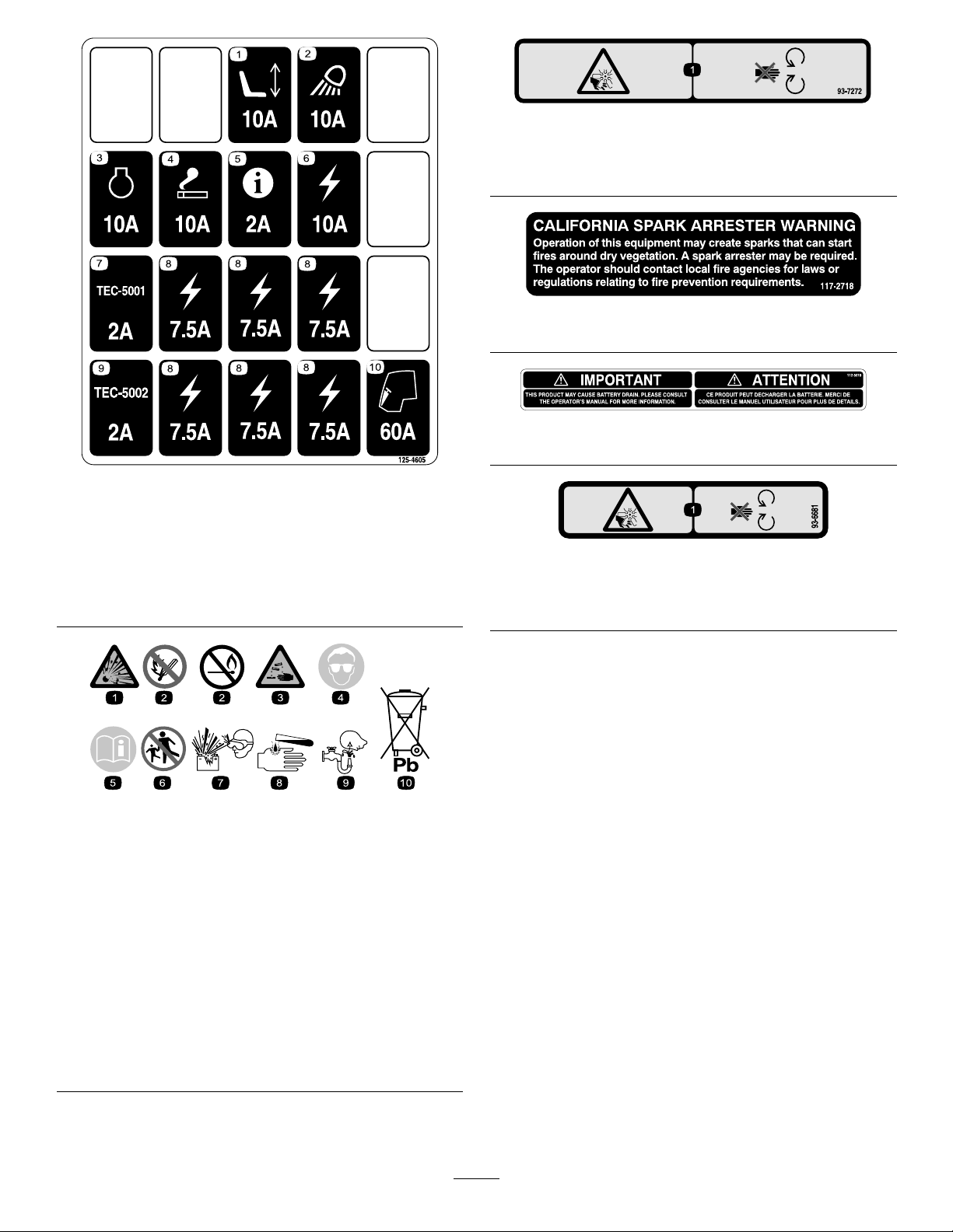
125-4605
1.Powerseat,10A6.Powersupplied,10A
2.Worklight,10A
3.Engine,10A8.Powersupplied,7.5A
4.Cigarettelighter,10A9.TEC-5002,2A
5.Infocenter,2A10.Cab,60A
7.TEC-5001,2A
decal93-7272
93-7272
1.Cutting/dismembermenthazard;fan—stayawayfrom
movingparts.
decal117-2718
117–2718
decal112-5019
112-5019
decal125-4605
decal93-6681
93-6681
1.Cutting/dismembermenthazard,fan—stayawayfrom
movingparts.
BatterySymbols
Someorallofthesesymbolsareonyourbattery
1.Explosionhazard
2.Nore,opename,or
smoking.
3.Causticliquid/chemical
burnhazard
4.Weareyeprotection9.Flusheyesimmediately
5.ReadtheOperator's
Manual.
6.Keepbystandersasafe
7.Weareyeprotection;
8.Batteryacidcancause
10.Containslead;donot
decalbatterysymbols
distancefromthebattery.
explosivegasescan
causeblindnessandother
injuries
blindnessorsevereburns.
withwaterandgetmedical
helpfast.
discard.
12
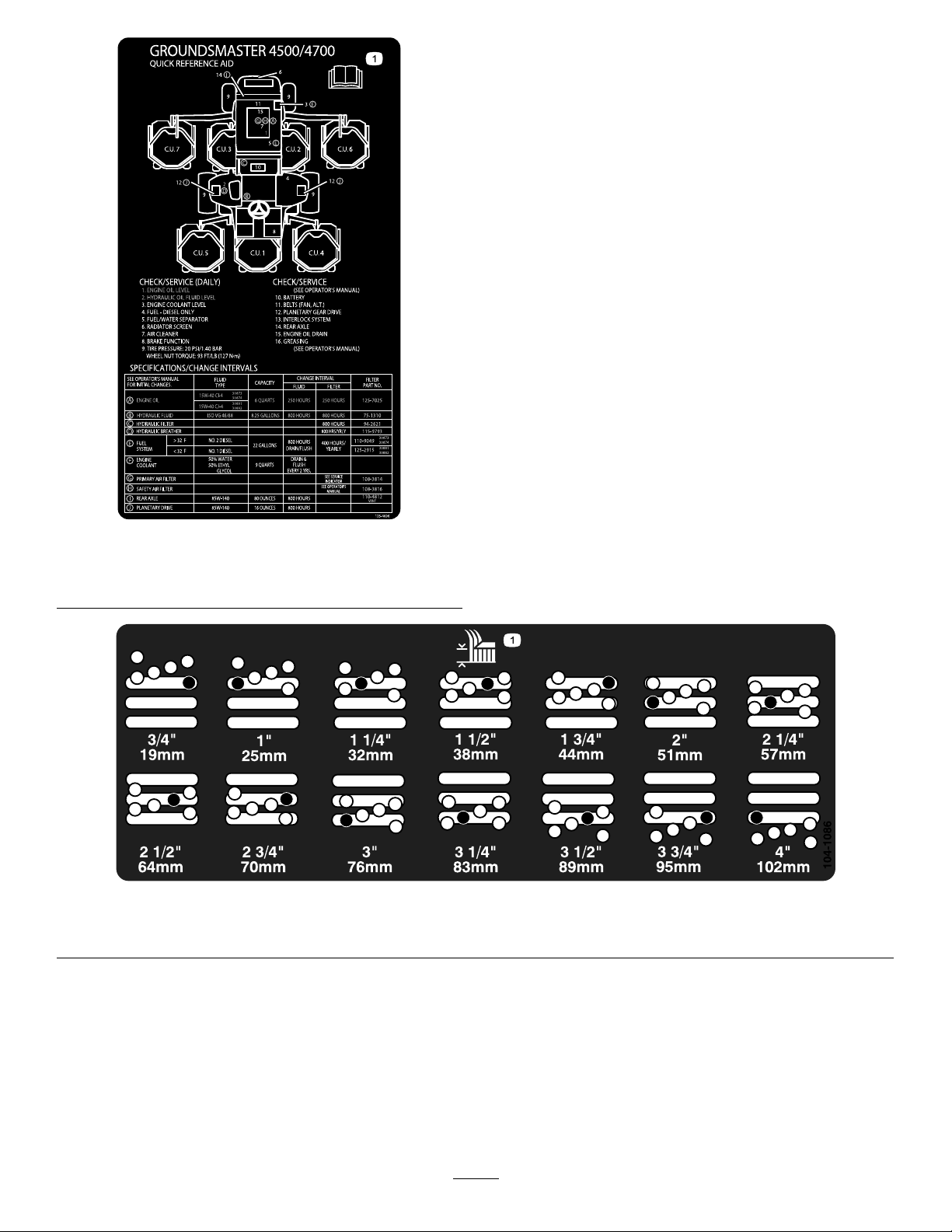
125–4606
1.ReadtheOperator’sManualforinformationon
maintenance.
1.Heightofcut
decal125-4606
decal104-1086
104-1086
13

Setup
LooseParts
Usethechartbelowtoverifythatallpartshavebeenshipped.
ProcedureDescription
Lockbracket1
Rivet2
1
2
3
4
5
6
Washer1
Screw,1/4x2inches
Locknut,1/4inch
Nopartsrequired
Nopartsrequired
Nopartsrequired
Nopartsrequired
Nopartsrequired
MediaandAdditionalParts
Description
WarningDecal6
Qty.
Qty.
InstalltheHoodLatch(CE).
1
1
–
–
–
–
–
AfxtheCEwarningdecalsoverthecorresponding
Englishwarningdecals.
Adjusttheheightofcut.
Adjusttherollerscraper(Optional).
Installthemulchingbafe(Optional).
Greasethemachine.
Checktherearaxlelubricant,hydraulic
uid,andengine-oillevels.
Use
Use
Operator'sManual
EngineOperator'sManual
PartsCatalog
OperatorTrainingMaterial
1
1
1
1
Readbeforeoperatingthemachine.
Readbeforeoperatingtheengine.
Usetoreferencepartnumbers.
Viewbeforeoperatingthemachine.
Note:Determinetheleftandrightsidesofthemachinefromthenormaloperatingposition.
14

1
InstallingtheHoodLatch
(CEOnly)
Partsneededforthisprocedure:
1Lockbracket
2Rivet
1Washer
1
Screw,1/4x2inches
1
Locknut,1/4inch
Procedure
1.Unhookthehoodlatchfromthehood-latch
bracket.
2.Removethe2rivetssecuringthehood-latch
brackettothehood(Figure3).Removethe
hood-latchbracketfromthehood.
Figure4
1.CElockbracket
4.Alignthewasherswiththeholesontheinsideof
thehood.
5.Rivetthebracketsandthewasherstothehood
(Figure4).
6.Hookthelatchontothehood-latchbracket
(Figure5).
2.Boltandnutassembly
g012629
Figure3
1.Hood-latchbracket2.Rivets
3.Whilealigningthemountingholes,positionthe
CElockbracketandthehoodlatchbracketonto
thehood.Thelockbracketmustbeagainstthe
hood(Figure4).Donotremovetheboltandnut
assemblyfromthelock-bracketarm.
g012630
Figure5
1.Hoodlatch
g012628
7.Screwtheboltintotheotherarmofhoodlock
brackettolockthelatchinposition(Figure6).
Tightentheboltbutdonottightenthenut.
15

Figure6
g012631
1.Bolt
2.Nut
3.Armofhood-lockbracket
2
AdjustingtheHeightofCut
NoPartsRequired
Procedure
Important:Thiscuttingdeckoftencuts
approximately6mm(1/4inch)lowerthanareel
cuttingunitwiththesamebenchsetting.Itmay
benecessarytohavetheserotarycuttingdeck’s
benchset6mm(1/4inch)abovethatofreels
cuttinginthesamearea.
Important:Accesstotherearcuttingunitsis
greatlyimprovedbyremovingthecuttingunit
fromthetractor.Iftheunitisequippedwitha
Sidewinder®,sidewindthecuttingunitstothe
right,removetherearcuttingunit,andslideitout
totherightside.
1.Lowerthecuttingdecktotheground,turnthe
keyintheignitionswitchtotheOFFposition,
andremovethekey.
2.Loosentheboltsecuringeachheight-of-cut
brackettotheheight-of-cutplate(frontandeach
side)(Figure7).
3.Beginningwithfrontadjustment,removethe
bolt.
g011344
Figure7
1.Height-of-cutbracket3.Spacer
2.Height-of-cutplate
4.Whilesupportingthechamber,removethe
spacer(Figure8).
5.Movethechambertothedesiredheight-of-cut
andinstallaspacerintothedesignatedheight
ofcutholeandslot(Figure8).
g026184
Figure8
6.Positionthetappedplatein-linewiththespacer.
7.Installtheboltngertight.
8.Repeatsteps4through7foreachside
adjustment.
9.Torqueall3boltsto41N-m(30ft-lb).Always
tightenthefrontboltrst.
Note:Adjustmentsofmorethan3.8cm(1–1/2
inches)mayrequiretemporaryassemblyto
anintermediateheighttopreventbinding(e.g.
changingfrom3.1to7cm(1.25to2.75inches)
heightofcut).
16

3
AdjustingtheRoller
Scraper(Optional)
NoPartsRequired
Procedure
Theoptionalrearrollerscraperisdesignedtowork
bestwhenthereisanevengapof0.5to1mm(0.020
to0.040inch)betweenthescraperandroller.
1.Loosenthegreasettingandthemounting
screw(Figure9).
Figure9
g011347
Figure10
1.Mulchingbafe
3.Verifythatmulchingbafedoesnotinterferewith
thetipofthebladeanddoesnotprotrudeinside
thesurfaceoftherearchamberwall.
WARNING
Donotusethehighliftbladewiththe
mulchingbafe.Thebladecouldbreak,
g011346
resultinginpersonalinjuryordeath.
1.Rollerscraper
2.Mountingscrew
2.Slidethescraperupordownuntilagapof0.5to
1mm(0.020to0.040inch)isachievedbetween
therodandtheroller.
3.Securethegreasettingandtorqueto41N-m
(30ft-lb)inanalternatingsequence.
3.Greasetting
4
InstallingtheMulching
Bafe(Optional)
NoPartsRequired
Procedure
1.Thoroughlycleandebrisfromthemounting
holesontherearwallandleftsidewallofthe
chamber.
2.Installthemulchingbafeintherearopening
andsecureitwith5angeheadbolts(Figure
10).
5
GreasingtheMachine
NoPartsRequired
Procedure
Greasethemachinebeforeoperatingtoensurethatit
isproperlylubricated.RefertoGreasingtheBearings
andBushings(page49).Failuretoproperlygreasethe
machineresultsinprematurefailureofcriticalparts.
17

ProductOverview
6
CheckingFluidLevels
NoPartsRequired
Procedure
1.Checktherearaxlelubricantlevelbeforethe
engineisrststarted;refertoCheckingtheRear
AxleLubricant(page60).
2.Checkthehydraulic-uidlevelbeforethe
engineisrststarted;refertoCheckingthe
Hydraulic-FluidLevel(page29).
3.Checktheengine-oillevelbeforeandafterthe
engineisrststarted;refertoCheckingthe
Engine-OilLevel(page52).
Controls
BrakePedals
2footpedals(Figure11)operateindividualwheel
brakesforturningassistanceandtoaidinobtaining
bettersidehilltraction.
Pedal-LockingLatch
Thepedal-lockinglatch(Figure11)connectsthe
pedalstogethertoengagetheparkingbrake.
Parking-BrakePedal
Toengagetheparkingbrake,(Figure11)connectthe
pedalstogetherwiththepedal-lockinglatch,push
downontherightbrakepedalwhileengagingthetoe
pedal.Toreleasetheparkingbrake,press1ofthe
brakepedalsuntiltheparkingbrake-latchretracts.
Figure11
1.Brakepedal4.Tractionpedal
2.Pedal-lockinglatch5.Tilt-steeringpedal
3.Parking-brakepedal
TractionPedal
Thetractionpedal(Figure11)controlsforwardand
reverseoperation.Depressthetopofthepedalto
moveforwardandthebottomtomovebackward.
Tostop,reduceyourfootpressureonthetraction
pedalandallowittoreturntothecenterposition.
Tilt-SteeringPedal
Totiltthesteeringwheeltowardsyou,pressthefoot
pedal(Figure11)down,andpullthesteeringtower
towardyoutothemostcomfortablepositionandthen
releasethepedal.
g009979
18

KeySwitch
LiftSwitches
Thekeyswitch(Figure12)has3positions:OFF,
ON/PREHEAT,andSTART.
PTOSwitch
ThePTOswitch(Figure12)has2positions:Out
(start)andIn(stop).PullthePTObuttonoutto
engagethecuttingunitblades.Pushinthebuttonto
disengagethecuttingunitblades.
Hi-LoSpeedControl
Theswitch(Figure12)allowsthespeedrangeto
increasefortransportingthemachine.Toswitch
betweentheHiandLospeedranges,raisethe
decks,disengagethePTO,putthetractionpedalinto
NEUTRAL,andmovethemachineataslowspeed..
Note:Thecuttingdecksdonotoperateand/or
cannotbeloweredfromthetransportpositionwhen
theswitchisinthehighrange.
Theliftswitches(Figure12)raiseandlowerthe
cuttingunits.Presstheswitchesforwardtolowerthe
cuttingunitsandbackwardtoraisethecuttingunits.
Whenstartingthemachine,withthecuttingunitsin
thedownposition,presstheliftswitchdowntoallow
thecuttingunitstooatandmow.
Note:ThedecksdonotlowerwhileintheHispeed
rangeandtheydonotraiseorloweriftheoperatoris
outoftheseatwhentheengineisrunning.Tolower
thedecksforservice,rotatethekeyintheignition
switchtotheONpositionwhilesittingintheseat.
LightSwitch
Presstheloweredgeoftheswitch(Figure12)toturn
onthelights.Presstheupperedgeoftheswitchto
turnoffthelights.
PowerPoint
Thepowerpoint(Figure13)isusedtopoweroptional
12Velectricalaccessories.
Figure12
1.Liftswitches(GM4700
only)
2.Liftswitch(GM4500and
4700)
3.PTOswitch
4.Keyswitch
5.InfoCenter
6.Hi-Lospeedcontrol
7.Engine-speedswitch
8.Lightswitch
9.Cruisecontrol
Engine-SpeedSwitch
Theengine-speedswitch(Figure12)has2modesto
changetheenginespeed.Taptheswitchtoincrease
ordecreasetheenginespeedin100rpmincrements.
Holdtheswitchdowntoautomaticallymovethe
enginetoHighorLowidle,dependingonwhichside
oftheswitchisdepresses.
g020433
g020512
Figure13
1.Powerpoint2.Bagholder
BagHolder
Usethebagholder(Figure13)forstorage.
19

SeatAdjustments
UsingtheInfoCenterLCDDisplay
ForeandAftAdjustingLever
Pulloutonthelevertoslidetheseatforeoraft(Figure
14).
SeatArmRestAdjustingKnob
Rotatetheknobtoadjusttheseatarmrestangle.
SeatBackAdjustingLever
Movethelevertoadjusttheseatbackangle(Figure
14).
Weightgauge
Indicateswhentheseatisadjustedtotheweightof
theoperator(Figure14).Heightadjustmentismade
bypositioningthesuspensionwithintherangeofthe
greenregion.
TheInfoCenterLCDdisplayshowsinformationabout
yourmachinesuchastheoperatingstatus,various
diagnostics,andotherinformationaboutthemachine
(Figure15).Thereisasplashscreenandamain
informationscreenontheInfoCenter.Pressanyof
theInfoCenterbuttonsandthenselecttheappropriate
directionalarrowtoswitchbetweenthesplashscreen
andthemaininformationscreen.
g020650
Figure15
Figure14
1.Weightgauge
2.Weight-adjustinglever5.Arm-restadjustingknob
3.ForeandAftadjusting
lever
Weight-AdjustingLever
4.Seat-backadjustinglever
(notshown-locatedunder
armrest)
1.Indicatorlight3.Middlebutton
2.Rightbutton
4.Leftbutton
•LeftButton(MenuAccess/BackButton)—pressto
accesstheInfoCentermenus.Youcanuseitto
backoutofanymenuyouarecurrentlyusing.
•MiddleButton—presstoscrolldownmenus.
•RightButton—presstoopenamenuwherearight
arrowindicatesadditionalcontent.
•Beeper—activatedwhenloweringthedecksorfor
g008837
advisoriesandfaults.
Note:Thepurposeofeachbuttonmaychange
dependingonwhatisrequiredatthetime.Each
buttonislabeledwithanicondisplayingitscurrent
function.
Adjustforoperatorweight(Figure14).Pulluponthe
levertoincreasetheairpressureandpushdownto
decreasetheairpressure.Theproperadjustmentis
attainedwhentheweightgaugeisinthegreenregion.
20

InfoCenterIconDescription
SERVICEDUE
Indicateswhenscheduledservice
shouldbeperformed
Thestatusoftheenginerpm.
InfoCenterIconDescription(cont'd.)
Stoptheengine.
Infoicon
Maximumtractionspeedsetting
Fast
Slow
Thefanisreversed.
Stationaryregenerationisrequired.
Theair-intakeheaterisactive.
Raisetheleftdeck.
Raisethecenterdeck.
Raisetherightdeck.
Sitintheseat.
Theparkingbrakeison.
Therangeishigh.
Neutralposition
Therangeislow.
CoolantTemperature(°Cor°F)
Temperature(hot)
TractionorTractionPedal
Notallowed
Starttheengine.
ThePTOison.
Engine
Keyswitch
Cuttingunitsarelowering.
Cuttingunitsareraising.
PINcode
Hydraulicoiltemperature
CANbus
InfoCenter
Badorfailed
Center
Right
Left
Bulb
OutputofTECcontrollerorcontrol
wireinharness
Overtheallowedrange
Undertheallowedrange
Outofrange
/
Switch
Operatormustreleaseswitch.
Operatorshouldchangetoindicated
state.
Symbolsareoften
combinedtoform
sentences.Some
examplesareshown
below
21

InfoCenterIconDescription(cont'd.)
Operatorshouldputmachinein
neutral.
Enginestartisdenied.
Engineshutdown
Enginecoolantistoohot.
Service
MenuItemDescription
Hours
CountsListsthenumberofstarts,
Liststhetotalnumberofhours
thatthemachine,engineand
fanhavebeenon,aswell
asthenumberofhoursthe
machinehasbeentransported
andoverheated.
deckPTOcycles,andfan
reversalsthemachinehas
experienced.
Hydraulicoilistoohot.
DPFashaccumulationnotication;
refertoServicingtheDiesel-Oxidation
Catalyst(DOC)andtheSootFilter
(page53).
Sitdownorsetparkingbrake
UsingtheMenus
ToaccesstheInfoCentermenusystem,pressthe
menuaccessbuttonwhileatthemainscreen.This
bringsyoutothemainmenu.Refertothefollowing
tablesforasynopsisoftheoptionsavailablefrom
themenus:
MainMenu
MenuItemDescription
Faults
ServiceContainsinformationonthe
DiagnosticsListsvariousstatesthatthe
Settings
AboutListsthemodelnumber,serial
Containsalistoftherecent
machinefaults.Referto
theServiceManualoryour
ToroDistributorformore
informationontheFaults
menuandtheinformation
containedthere.
machinesuchashoursofuse
andothersimilarnumbers.
machinecurrentlyhas.You
canusethistotroubleshoot
certainissuesasitquicklytells
youwhichmachinecontrols
areonandwhichareoff.
Allowsyoutocustomizeand
modifycongurationvariables
ontheInfoCenterdisplay.
number,andsoftwareversion
ofyourmachine.
Diagnostics
MenuItemDescription
LeftDeck
CenterDeck
RightDeck
TractionPedal
Traction
HI/LORange
PTO
EngineRun
Settings
MenuItemDescription
Units
Language
LCDBacklightControlsthebrightnessofthe
LCDContrastControlsthecontrastofthe
ProtectedMenusAllowsapersonauthorized
ProtectSettings
AutoIdle
MowSpeedControlsthemaximumspeed
Trans.SpeedControlsthemaximumspeed
CounterbalanceControlstheamountof
RefertotheServiceManualor
yourToroDistributorformore
informationontheEngine
Runmenuandtheinformation
containedthere.
Controlstheunitsusedonthe
InfoCenter(EnglishorMetric).
Controlsthelanguageused
ontheInfoCenter*.
LCDdisplay.
LCDdisplay.
byyourcompanywiththe
PINcodetoaccessprotected
menus.
Allowstheabilitytochange
thesettingsintheprotected
settings.
Controlstheamountoftime
allowedbeforeidlingthe
enginewhenthemachineis
notinuse.
whileinmow(lowrange).
whileintransport(highrange).
counterbalanceappliedbythe
decks.
*Only"operator-faced"textistranslated.Faults,
Service,andDiagnosticsscreensare"service-faced.”
Titlesareintheselectedlanguage,butmenuitems
areinEnglish.
22

About
MenuItemDescription
Model
SNListstheserialnumberofthe
S/WRevListsthesoftwarerevisionof
Liststhemodelnumberofthe
machine.
machine.
themastercontroller .
ProtectedMenus
Thereare5operatingcongurationsettingsthatare
adjustablewithintheSettingsMenuoftheInfoCenter:
autoidle,maximummowinggroundspeed,maximum
transportgroundspeed,SmartPower,anddeck
counterbalance.ThesesettingsareintheProtected
Menu.
AccessingProtectedMenus
Note:ThefactorydefaultPINcodeforyoumachine
iseither0000or1234.
IfyouchangedthePINcodeandforgotthe
code,contactyourAuthorizedT oroDistributorfor
assistance.
1.FromtheMAINMENU,usethecenterbuttonto
scrolldowntotheSETTINGSMENUandpressthe
rightbutton(Figure16).
Figure16
2.IntheSETTINGSMENU,usethecenterbuttonto
scrolldowntothePROTECTEDMENUandpress
therightbutton(Figure17A).
g028522
Figure17
3.ToenterthePINcode,pressthecenterbutton
untilthecorrectrstdigitappears,thenpress
therightbuttontomoveontothenextdigit
(Figure17BandFigure17C).Repeatthisstep
untilthelastdigitisenteredandpresstheright
buttononcemore.
4.PressthemiddlebuttontoenterthePINcode
(Figure17D).
WaituntiltheredindicatorlightoftheInfoCenter
illuminates.
Note:IftheInfoCenteracceptsthePINcode
andtheprotectedmenuisunlocked,theword
“PIN”displaysintheupperrightcornerofthe
screen.
g028523
Note:RotatethekeyswitchtotheOFFpositionand
thentotheONpositionlockstheprotectedmenu.
Youhavetheabilitytoviewandchangethesettingsin
theProtectedMenu.OnceyouaccesstheProtected
Menu,scrolldowntoProtectSettingsoption.Usethe
rightbuttontochangethesetting.SettingtheProtect
SettingstoOFFallowsyoutoviewandchangethe
settingsintheProtectedMenuwithoutenteringthe
PINcode.SettingtheProtectSettingstoONhidesthe
protectedoptionsandrequiresyoutoenterthePIN
codetochangethesettingintheProtectedMenu.
AfteryousetthePINcode,rotatethekeyswitchOFF
andbacktotheONpositiontoenableandsavethis
feature.
23

Viewingthechangingthe
SettingtheMaximumAllowed
ProtectedMenuSettings
1.IntheProtectedMenu,scrolldowntoProtect
Settings.
2.Toviewandchangethesettingswithoutentering
apasscode,usetherightbuttontochangethe
ProtectSettingstoOFF.
3.Toviewandchangethesettingswitha
passcode,usetheleftbuttontoselectON,set
thepasscode,andturnthekeyintheignition
switchtotheOFFpositionandthentotheON
position.
SettingtheAutoIdle
1.IntheSettingsMenu,scrolldowntoAutoIdle.
2.Presstherightbuttontochangetheautoidle
timebetweenOFF,8S,10S,15S,20S,and30S.
SettingtheMaximumAllowed
MowSpeed
1.IntheSettingsMenu,ScrolldowntoMowSpeed
andpresstherightbutton.
2.Usetherightbuttontoincreasethemaxfull
mowspeed(50%,75%,or100%).
3.Usethecenterbuttontodecreasethemaxfull
mowspeed(50%,75%,or100%).
TransportSpeed
1.IntheSettingsMenu,scrolldowntoTransport
Speedandpresstherightbutton.
2.Usetherightbuttontoincreasethemax
transportspeed(50%,75%,or100%).
3.Usethecenterbuttontodecreasethemax
transportspeed(50%,75%,or100%).
4.Presstheleftbuttontoexit.
TurningtheSmartPowerON/OFF
1.Inthesettingsmenu,scrolldowntoSmart
Power.
2.PresstherightbuttontoswitchbetweenONand
OFF.
3.Presstheleftbuttontoexit.
SettingtheCounterbalance
1.IntheSettingsMenu,scrolldowntoCounter
Balanceandpresstherightbutton.
2.PresstherightbuttontoswitchbetweenLow,
Med,andHigh.
WhennishedwiththeProtectedMenu,presstheleft
buttontoexittotheMainMenu,thenpresstheleft
buttontoexittotheRunMenu.
4.Presstheleftbuttontoexit.
24

Specications
Note:Specicationsanddesignaresubjectto
changewithoutnotice.
4500-D4700-D
Widthofcut2.8m(109inches)3.8m(150inches)
Overallwidth,
cuttingunits
down
Overallwidth,
cuttingunitsup
(transport)
Overalllength370cm(145.8inches)370cm(145.8inches)
Heightwith
ROPS
Ground
clearance
TrackWidth,
front
TrackWidth,
rear
Wheelbase
NetWeight(with
cuttingunitsand
nouids)
286cm(1 12.8inches)391cm(153.8inches)
224cm(88.25inches)224cm(88.25inches)
216cm(85inches)216cm(85inches)
15cm(6inches)15cm(6inches)
224cm(88.25inches)224cm(88.25inches)
141cm(55.5inches)141cm(55.5inches)
171cm(67–1/2inches)171cm(67–1/2inches)
1894kg(4175lb)2234kg(4925lb)
CuttingDeck
Length
Width
Height
Weight
86.4cm(34inches)
86.4cm(34inches)
24.4cm(9.6inches)
tocarriermount
26.7cm(10–1/2inches)
at3/4inchheightofcut
34.9cm(13–3/4inches)at
4inchheightofcut
88kg(195pounds)
Attachments/Accessories
AselectionofT oroapprovedattachmentsand
accessoriesisavailableforusewiththemachineto
enhanceandexpanditscapabilities.Contactyour
AuthorizedServiceDealerorDistributororgoto
www.T oro.comforalistofallapprovedattachments
andaccessories.
Tobestprotectyourinvestmentandmaintainoptimal
performanceofyourToroequipment,countonToro
genuineparts.Whenitcomestoreliability,T oro
deliversreplacementpartsdesignedtotheexact
engineeringspecicationofourequipment.Forpeace
ofmind,insistonTorogenuineparts.
25

Operation
Note:Determinetheleftandrightsidesofthe
machinefromthenormaloperatingposition.
CAUTION
Thismachineproducessoundlevelsthatcan
causehearinglossthroughextendedperiods
ofexposure.
CAUTION
Thismachineproducessoundlevelsin
excessof85dBAattheoperator'searand
cancausehearinglossthroughextended
periodsofexposure.
Wearhearingprotectionwhenoperatingthis
machine.
CAUTION
Ifyouleavethekeyintheignitionswitch,
someonecouldaccidentlystarttheengine
andseriouslyinjureyouorotherbystanders.
Removethekeyfromtheignitionbeforeyou
doanymaintenance.
ThinkSafetyFirst
Carefullyreadallsafetyinstructionsandsymbolsin
thesafetysection.Knowingthisinformationcould
helpyouorbystandersavoidinjury.
DANGER
Operatingonwetgrassorsteepslopescan
causeslidingandlossofcontrol.
Wheelsdroppingoveredgescancause
rollovers,whichmayresultinseriousinjury,
death,ordrowning.
Thereisnorolloverprotectionwhentheroll
barisdown.
Alwayskeeptherollbarinthefullyraisedand
lockedpositionandusetheseatbelt.
Readandfollowtherolloverprotection
instructionsandwarnings.
Wearhearingprotectionwhenoperatingthis
machine.
Theuseofprotectiveequipmentforeyes,ears,
hands,feet,andheadisrecommended.
Figure18
1.Wearsafetyglasses.
2.Wearhearingprotection.
CheckingtheCooling
System
ServiceInterval:Beforeeachuseordaily
Checklevelofcoolantatthebeginningofeachday.
Capacityofsystemis8.5L(9USqt).
1.Carefullyremovetheradiatorcap.
CAUTION
Iftheenginehasbeenrunning,the
pressurized,hotcoolantcanescapeand
causeburns.
•Donotopentheradiatorcapwhenthe
engineisrunning.
•Usearagwhenopeningtheradiator
cap,andopenthecapslowlytoallow
steamtoescape.
g009027
Toavoidlossofcontrolandpossibilityof
rollover:
•Donotoperateneardrop-offsornear
water.
•Donotoperateonslopesgreaterthan
20degrees.
•Reducespeedanduseextremecautionon
slopes.
•Avoidsuddenturnsorrapidspeed
changes.
26

Figure19
1.Expansiontank
2.Checkthecoolantlevelintheradiator.The
radiatorshouldbelledtothetopoftheller
neckandtheexpansiontanklledtotheFull
mark(Figure19).
3.Ifthecoolantislow,adda50/50mixtureofwater
andethyleneglycolantifreeze.Donotuse
wateronlyoralcohol/methanolbasecoolants.
4.Installtheradiatorcapandexpansiontankcap.
DANGER
Incertainconditions,fuelisextremely
ammableandhighlyexplosive.Areor
explosionfromfuelcanburnyouandothers
andcandamageproperty.
•Fillthefueltankoutdoors,inanopenarea,
whentheengineiscold.Wipeupanyfuel
thatspills.
•Neverllthefueltankinsideanenclosed
trailer.
•Neversmokewhenhandlingfuel,andstay
awayfromanopenameorwherefuel
fumesmaybeignitedbyaspark.
•Storefuelinanapprovedcontainerand
keepitoutofthereachofchildren.Never
g009702
buymorethana180-daysupplyoffuel.
•Donotoperatemachinewithoutentire
exhaustsysteminplaceandinproper
workingcondition.
DANGER
Incertainconditionsduringfueling,static
electricitycanbereleasedcausingaspark
whichcanignitethefuelvapors.Areor
explosionfromfuelcanburnyouandothers
andcandamageproperty.
CheckingtheEngine-Oil
Level
Beforeyoustarttheengineandusethemachine,
checktheoillevelintheenginecrankcase;referto
CheckingtheEngine-OilLevel(page52).
FillingtheFuelTank
WARNING
Fuelisharmfulorfatalifswallowed.
Long-termexposuretovaporscancause
seriousinjuryandillness.
•Avoidprolongedbreathingofvapors.
•Keepfaceawayfromnozzleandfueltank
orconditioneropening.
•Keepfuelawayfromeyesandskin.
•Alwaysplacefuelcontainersontheground
awayfromyourvehiclebeforelling.
•Donotllfuelcontainersinsideavehicle
oronatruckortrailerbedbecauseinterior
carpetsorplastictruckbedlinersmay
insulatethecontainerandslowthelossof
anystaticcharge.
•Whenpractical,removeequipmentfrom
thetruckortrailerandrefueltheequipment
withitswheelsontheground.
•Ifthisisnotpossible,thenrefuelsuch
equipmentonatruckortrailerfroma
portablecontainer,ratherthanfroma
fuel-dispensernozzle.
•Ifafuel-dispensernozzlemustbeused,
keepthenozzleincontactwiththerimof
thefueltankorcontaineropeningatall
timesuntilfuelingiscomplete.
27

FuelTankCapacity
Sulfurcontent:Ultra-lowsulfur(<15ppm)
Fueltankcapacity:83L(22USgallons)
FuelSpecication
Important:Useonlyultra-lowsulphurdiesel
fuel.Fuelwithhigherratesofsulfurdegrades
thedieseloxidationcatalyst(DOC),whichcauses
operationalproblemsandshortenstheservicelife
ofenginecomponents.
Failuretoobservethefollowingcautionsmay
damagetheengine.
•Neverusekeroseneorgasolineinsteadofdiesel
fuel.
•Nevermixkeroseneorusedengineoilwiththe
dieselfuel.
•Neverkeepfuelincontainerswithzincplatingon
theinside.
•Donotusefueladditives.
PetroleumDiesel
Cetanerating:45orhigher
Sulfurcontent:Ultra-lowsulfur(<15ppm)
FuelTable
Dieselfuelspecication
ASTMD975
No.1-DS15
No.2-DS15
EN590EuropeanUnion
ISO8217DMX
JISK2204GradeNo.2
KSM-2610
Location
USA
International
Japan
Korea
Biodieselfuelspecication:ASTMD6751or
EN14214
Blendedfuelspecication:ASTMD975,EN590,
orJISK2204
Important:Thepetroleumdieselportionmust
beultra-lowsulfur.
Observethefollowingprecautions:
•Biodieselblendsmaydamagepaintedsurfaces.
•UseB5(biodieselcontentof5%)orlesserblends
incoldweather.
•Monitorseals,hoses,gasketsincontactwithfuel
astheymaybedegradedovertime.
•Fuellterpluggingmaybeexpectedforatime
afterconvertingtobiodieselblends.
•ContactyourAuthorizedT oroDistributorifyou
wishformoreinformationonbiodiesel.
AddingFuel
Fillthetankwithdieselfueluntilthelevelreachesthe
bottomofthellerneck.
1.Parkthemachineonalevelsurface.
2.Cleanthearearoundthefuel-tankcapwitha
cleanrag.
3.Removethecapfromthefueltank(Figure20).
•Useonlyclean,freshdieselfuelorbiodieselfuels.
•Purchasefuelinquantitiesthatcanbeusedwithin
180daystoensurefuelfreshness.
Usesummer-gradedieselfuel(No.2-D)at
temperaturesabove-7°C(20°F)andwinter-grade
fuel(No.1-DorNo.1-D/2-Dblend)belowthat
temperature.
Note:Useofwinter-gradefuelatlowertemperatures
provideslowerashpointandcoldowcharacteristics
whicheasesstartingandreducesfuellterplugging.
Usingsummer-gradefuelabove-7°C(20°F)
contributestowardlongerfuelpumplifeandincreased
powercomparedtowinter-gradefuel.
Biodiesel
Thismachinecanalsouseabiodieselblendedfuelof
uptoB20(20%biodiesel,80%petroleumdiesel).
g011485
Figure20
1.Fuel-tankcap
4.Fillthetankwithdieselfueluntilthelevel
reachesthebottomofthellerneck.
5.Installthefuel-tankcaptightly.
Note:Ifpossible,llthefueltankaftereachuse.
Thisminimizespossiblebuildupofcondensation
insidethefueltank.
28

Note:Ifpossible,llthefueltankaftereachuse;this
willminimizepossiblebuildupofcondensationinside
thefueltank.
Checkingthe
Hydraulic-FluidLevel
ServiceInterval:Beforeeachuseordaily
USgallons)containersor208L(55USgallons)
drumsfromyourMobilDistributor.
Important:Manyhydraulicuidsarealmost
colorless,makingitdifculttospotleaks.A
reddyeadditiveforthehydraulicsystemoilis
availablein20ml(2/3oz)bottles.1bottleis
sufcientfor15to22L(4to6USgallons)of
hydraulicoil.OrderPartNumber44-2500from
yourToroDistributor.
Themachinesreservoirislledatthefactorywith
approximately28.4L(7.50USgallons)ofhighquality
hydraulicuid.Checkthelevelofthehydraulicuid
beforetheengineisrststartedanddailythereafter.
Therecommendedreplacementuidisasfollows:
ToroPremiumAllSeasonHydraulicFluid(Availablein18.9
L(5USgallons)pailsor208L(55USgallons)drums.See
thePartsCatalogoryourToroDistributorforpartnumbers.)
Alternateuids:IftheT orouidisnotavailable,other
uidsmaybeusedprovidedtheymeetallthefollowing
materialpropertiesandindustryspecications.We
donotrecommendtheuseofsyntheticuid.Consult
withyourlubricantdistributortoidentifyasatisfactory
product.
Note:Useproductsonlyfromreputable
manufactures.Torodoesnottakeresponsibilityfor
damagecausedbyimpropersubstitutions.
HighViscosityIndex/LowPourPointAnti-wearHydraulic
Fluid,ISOVG46
MaterialProperties:
Viscosity,ASTMD445cSt@40°C44to50
ViscosityIndexASTM
D2270
PourPoint,ASTMD97-34°Fto-49°F
IndustrySpecications:
VickersI-286-S(QualityLevel),VickersM-2950-S
(QualityLevel),DenisonHF-0
cSt@100°C7.9to8.5
140to160
1.Positionthemachineonalevelsurface,lower
thecuttingunits,turnthekeyintheignition
switchtotheOFFposition,andremovethekey .
2.Cleantheareaaroundthellerneckandcapof
thehydraulictank(Figure21).Removethecap
fromthellerneck.
g012394
Figure21
1.Hydraulic-tankcap
3.Removethedipstick,wipeitclean,installthe
dipstickintothetank,andpullitoutagain.
Important:TheISOVG46Multigradeuid
hasbeenfoundtoofferoptimalperformance
inawide-rangeoftemperatureconditions.
Foroperationinconsistentlyhighambient
temperatures,18°C(65°F)to49°C(120°F),
ISOVG68hydraulicuidmayofferimproved
performance.
PremiumBiodegradableHydraulicFluid-Mobil
EALEnviroSyn46H
Important:MobilEALEnviroSyn46Histheonly
syntheticbiodegradableuidapprovedbyToro.
Thisuidiscompatiblewiththeelastomersused
inTorohydraulicsystemsandissuitablefora
wide-rangeoftemperatureconditions.Thisuidis
compatiblewithconventionalmineraloils,butfor
maximumbiodegradabilityandperformancethe
hydraulicsystemshouldbethoroughlyushedof
conventionaluid.Theoilisavailablein19L(5
Note:Theuidlevelshouldbebetweenthe2
marksonthedipstick.
4.Ifthelevelislow,addtheappropriateuidto
raisetheleveltotheuppermark.
5.Installthedipstickandcapontothellerneck.
CheckingtheTirePressure
ServiceInterval:Beforeeachuseordaily
Thetiresareover-inatedforshipping.Therefore,
releasesomeoftheairtoreducethepressure.The
correctairpressureinthetiresis138kPa(20psi).
Important:Maintaintherecommended
pressureinalltirestoensurethatthereisa
goodquality-of-cutandforpropermachine
performance.Donotunder-inate.
29

StartingandStoppingthe
Engine
StartingtheEngine
Important:Youmustbleedthefuelsystembefore
startingtheengineiftheenginehasstoppeddue
tolackoffuel,oryouhaveperformedmaintenance
onthefuelsystem.
1.Sitontheseat,keepyourfootoffthetraction
pedalsothatitisinNEUTRAL,andengagethe
parkingbrake.
4.TurnthekeyintheignitionswitchtotheOFF
positionandremovethekey.
SmartPower
WithT oroSmartPower™,theoperatordoesnothave
tolistentotheenginespeedinheavyconditions.
SmartPowerpreventsboggingdowninheavyturf
byautomaticallycontrollingthemachinespeedand
optimizingcuttingperformance.
ReversingFanOperation
2.Turnthekeyintheignitionswitchtothe
RUNpositionandensuretheglowindicator
illuminates.
3.Whentheglowindicatordims,turnthekeyinthe
ignitionswitchtotheSTARTposition.Release
thekeyimmediatelywhentheenginestartsand
allowittoreturntotheRunposition.Adjustthe
enginespeed.
Important:Donotrunthestartermotor
morethan30secondsatatimeorpremature
starterfailuremayresult.Iftheenginefails
tostartafter30seconds,turnthekeyto
theOffposition,recheckthecontrolsand
procedures,wait30additionalseconds,and
repeatthestartingprocedure.
Whenthetemperatureislessthan-7°C(20°F),
thestartermotorcanberunfor30secondson
then60secondsofffor2attempts.
CAUTION
Shuttheengineoffandwaitforall
movingpartstostopbeforechecking
foroilleaks,looseparts,andother
malfunctions.
Thefanspeediscontrolledbythehydraulic-oil
temperatureandengine-coolanttemperature.A
reversecycleisautomaticallyinitiatedwheneither
theenginecoolantorhydraulicoiltemperature
reachesacertainpoint.Thisreversalhelpsblow
debrisofftherearscreenandlowerstheengineand
hydraulic-oiltemperatures.T omanuallyinitiatea
reversecycle,simultaneouslypresstheouterbuttons
ontheInfoCenterfor4seconds.Reversethefan
whentherearscreeniscloggedorpriortoentering
theshoporstoragearea.
AutoIdle
ThemachineisequippedwithAutoIdlewhich
automaticallyreturnstheenginetolowidlewhen
allofthefollowingfunctionsarenotused,forapre
determinedtime,previouslysetintheInfoCenter.
•Thetractionpedalisreturnedtotheneutral
position
•ThePTOisdisengaged
•Noneoftheliftswitchesareactivated
Note:Whenanyoftheabovefunctionsare
initiated,themachineautomaticallyreturnstothe
previousengine-speedsetting.
StoppingtheEngine
Important:Allowtheenginetoidlefor5minutes
beforeshuttingitoffafterafullloadoperation.
Thisallowstheturbochargertocooldownbefore
shuttingtheengineoff.Failuretodosomaylead
toturbo-chargertrouble.
Note:Lowerthecuttingunitstothegroundwhenever
machineisparked.Thisrelievesthehydraulicload
fromthesystem,preventswearonsystempartsand
alsopreventsaccidentalloweringofthecuttingunits.
1.MovethePTOswitchtotheOFFposition.
2.Settheparkingbrake.
3.Returntheenginelowidle.
Engine-SpeedSwitch
Theengine-speedswitchhas2modestochangethe
enginespeed.T oincreaseordecreasetheengine
speed(in100rmpincrements),taptheswitch.T o
automaticallymovetoHighorLowidle,holddownthe
switchtothedesiredside.
30

MowSpeed
Counterbalance
Supervisor(ProtectedMenu)
Allowsthesupervisortosetthemachine’smaximum
mowingspeed,inincrementsof50%,75%or100%,
atwhichtheoperatorcanmow(lowrange).
RefertoSettingtheMaximumAllowedMowSpeed
(page24)fortheproceduretosetthemowspeed.
Operator
Allowstheoperatortoadjustthemachine’smaximum
mowingspeed(lowrange),withinthesupervisors
pre-adjustedsettings.WhenintheInfoCentersplash
ormainscreen,pressthemiddlebutton(
toadjustthespeed.
Note:Whenswitchingbetweenlowandhighranges,
thesettingstransferbasedontheprevioussetting.
Thesettingsresetwhenthemachineisturnedoff.
TransportSpeed
Supervisor(ProtectedMenu)
Thecounterbalancesystemmaintainshydraulic
backpressureonthedeckliftcylinders.This
counterbalancepressuretransferscuttingdeckweight
tothemower'sdrivewheelstoimprovetraction.The
counterbalancepressurehasbeenfactorysettoan
optimalbalanceofafter-cutappearanceandtraction
capabilityinmostturfconditions.Decreasingthe
counterbalancesettingcanproduceamorestable
cuttingdeck,butcandecreasethetractioncapability .
Increasingthecounterbalancesettingcanincrease
thetractioncapability,butmayresultinaftercut
appearanceissues.
icon)
Duringdifferenttimesofthemowingseasonorwhen
turfconditionsvary,theamountofcounterbalance
(upwardlift)requiredonthecuttingdeckscanbe
changedtomeettheconditions.
RefertoSettingtheCounterbalance(page24)forthe
proceduretosetthecounterbalancepressure.
Allowsthesupervisortosetthemachinesmaximum
transportspeed,inincrementsof50%,75%or100%,
atwhichtheoperatorcantransport(highrange).
RefertoSettingtheMaximumAllowedTransport
Speed(page24)fortheproceduretosetthetransport
speed.
Operator
Allowstheoperatortoadjustthemachine’smaximum
transportspeed(highrange),withinthesupervisors
pre-adjustedsettings.WhenintheInfoCentersplash
ormainscreen,pressthemiddlebutton(
toadjustthespeed.
Note:Whenswitchingbetweenlowandhighranges,
thesettingstransferbasedontheprevioussetting.
Thesettingsresetwhenthemachineisturnedoff.
icon)
31

CheckingtheInterlock
CuttingGrasswiththe
Switches
ServiceInterval:Beforeeachuseordaily
CAUTION
Ifthesafety-interlockswitchesare
disconnectedordamagedthemachinecould
operateunexpectedlycausingpersonalinjury.
•Donottamperwiththeinterlockswitches.
•Checktheoperationoftheinterlock
switchesdailyandreplaceanydamaged
switchesbeforeoperatingthemachine.
Theinterlockswitchesaredesignedtostopthe
machinewhentheoperatorgetsofftheseatwhenthe
tractionpedalisdepressed.However,theoperator
maygetofftheseatwhiletheengineisrunningand
thetractionpedalisinneutral.Althoughtheengine
continuestorunifthePTOswitchisdisengaged
andthetractionpedalisreleased,itisstrongly
recommendedthattheenginebestoppedbefore
risingfromtheseat.
Tochecktheoperationoftheinterlockswitches,
performthefollowingprocedure:
1.Parkthemachineonalevelsurface,lowerthe
cuttingunit,turnthekeyintheignitionswitchto
theOFFposition,andengagetheparkingbrake.
Machine
Note:Cuttinggrassataratethatloadstheengine
promotesDPFregeneration.
1.Movethemachinetothejobsite.
2.Wheneverpossible,settheengine-speedswitch
tohighidle.
3.EngagethePTOswitch.
4.Graduallymovethetractionpedalforwardand
slowlydrivethemachineoverthemowingarea.
5.Oncethefrontofthecuttingunitsareoverthe
mowingarea,lowerthecuttingunits.
6.Cutgrasssothatthebladescancutand
dischargeclippingsatahighratewhile
producingagoodqualityofcut.
Note:Ifthecuttingrateistoohigh,thequality
ofcutmaydeteriorate.Reducetheground
speedofthemachineorreducethewidthofcut
toregainhighidleenginespeed.
7.Whenthecuttingunitsareoverthefaredgeof
themowingarea,liftthecuttingunits.
8.Performatear-shapedturntoquicklylineupfor
yournextpass.
2.Pressthetractionpedal.Turnthekeyinthe
ignitionswitchtotheONposition.
Note:Iftheenginecranks,thereisa
malfunctionintheinterlocksystem.Correctthis
malfunctionbeforeoperatingthemachine.
3.TurnthekeyintheignitionswitchtotheON
position,risefromtheseat,andmovethePTO
switchtoON.
Note:ThePTOshouldnotengage.Ifthe
PTOengages,thereisamalfunctioninthe
interlocksystem.Correctthismalfunctionbefore
operatingthemachine.
4.Engagetheparkingbrake,turnthekeyinthe
ignitionswitchtotheONposition,andmovethe
tractionpedaloutofNEUTRAL.
Note:TheInfoCenterdisplays"tractiondenied"
andthemachineshouldnotmove.Ifthe
machinedoesmove,thereisamalfunctionin
theinterlocksystem.Correctthismalfunction
beforeoperatingthemachine.
32

DieselParticulateFilter
Regeneration
Thedieselparticulatelter(DPF)ispartoftheexhaust
system.Thediesel-oxidationcatalystoftheDPF
reducesharmfulgassesandthesootlterremoves
sootfromtheengineexhaust.
TheDPFregenerationprocessusesheatfromthe
engineexhausttoincineratethesootaccumulatedon
thesootlter,convertingthesoottoash,andclears
thechannelsofthesootltersothatlteredengine
exhaustowsouttheDPF .
Theenginecomputermonitorstheaccumulationof
sootbymeasuringthebackpressureintheDPF.If
thebackpressureistoohigh,sootisnotincinerating
inthesootlterthroughnormalengineoperation.T o
keeptheDPFclearofsoot,rememberthefollowing:
•Passiveregenerationoccurscontinuouslywhile
theengineisrunning—runtheengineatfull
enginespeedwhenpossibletopromoteDPF
regeneration.
•Ifthebackpressureistoohigh,theengine
computersignalsyouthroughtheInfoCenter
whenadditionalprocesses(assistandreset
regeneration)arerunning.
•Allowtheassistandresetregenerationprocessto
completebeforeshuttingofftheengine.
Operateandmaintainyourmachinewiththefunction
oftheDPFinmind.Engineloadathighidle
enginespeedgenerallyproduceadequateexhaust
temperatureforDPFregeneration.
Important:Minimizetheamountoftimethatyou
idletheengineoroperatetheengineatlow-engine
speedtohelpreducetheaccumulationofsootin
thesootlter.
CAUTION
Theexhausttemperatureishot(approximately
600°C(1112°F)duringDPFparked
regenerationorrecoveryregeneration.Hot
exhaustgascanharmyouorotherpeople.
•Neveroperatetheengineinanenclosed
area.
•Makesurethattherearenoammable
materialsaroundtheexhaustsystem.
•Nevertouchahotexhaustsystem
component.
•Neverstandnearoraroundtheexhaust
pipeofthemachine.
DPFSootAccumulation
•Overtime,theDPFaccumulatessootinthesoot
lter.Thecomputerfortheenginemonitorsthe
sootlevelintheDPF .
•Whenenoughsootaccumulates,thecomputer
informsyouthatitistimetoregeneratethediesel
particulatelter.
•DPFregenerationisaprocessthatheatstheDPF
toconvertthesoottoash.
•Inadditiontothewarningmessages,thecomputer
reducesthepowerproducedbytheengineat
differentsoot-accumulationlevels.
EngineWarningMessages—SootAccumulation
IndicationLevel
Level1:Engine
Warning
Level2:Engine
Warning
FaultCode
g213866
Figure22
CheckEngine
SPN3719,FMI16
g213867
Figure23
CheckEngine
SPN3719,FMI0
EnginePowerRatingRecommendedAction
Thecomputerde-ratesthe
enginepowerto85%
Thecomputerde-ratesthe
enginepowerto50%
Performaparkedregeneration
assoonaspossible;referto
ParkedRegeneration(page37).
Performarecoveryregeneration
assoonaspossible;referto
RecoveryRegeneration
(page40).
33

DPFAshAccumulation
•Thelighterashisdischargedthroughtheexhaust
system;theheavierashcollectsinthesootlter.
•Ashisaresidueoftheregenerationprocess.Over
time,thedieselparticulatelteraccumulatesash
thatdoesnotdischargewiththeengineexhaust.
•Thecomputerfortheenginecalculatestheamount
ofashaccumulatedintheDPF.
InfoCenterAdvisoryandEngineWarningMessages—AshAccumulation
•Whenenoughashaccumulates,theengine
computersendsinformationtotheInfoCenterin
theformofasystemadvisoryoranenginefaultto
indicatetheaccumulationofashintheDPF .
•Theadvisoryandfaultsareindicationsthatitis
timetoservicetheDPF .
•Inadditiontothewarnings,thecomputerreduces
thepowerproducedbytheengineatdifferent
ash-accumulationlevels.
Indication
Level1:
System
Advisory
Level2:
Engine
Warning
Level3:
Engine
Warning
Level
AdvisoryorFaultCode
g213865
EngineSpeed
Reduction
None
EnginePowerRatingRecommendedAction
Notifyyourservice
100%
departmentthatadvisory
#179displaysinthe
InfoCenter.
Figure24
Advisory#179
ServicetheDPF;
refertoServicingthe
Diesel-OxidationCatalyst
(DOC)andtheSoot
Filter(page53)
g213863
Figure25
None
Thecomputer
de-ratestheengine
powerto85%
CheckEngine
SPN3720,FMI16
ServicetheDPF;
refertoServicingthe
Diesel-OxidationCatalyst
(DOC)andtheSoot
Filter(page53)
g213864
Figure26
None
Thecomputer
de-ratestheengine
powerto50%
CheckEngine
SPN3720,FMI0
Level4:
Engine
Warning
g214715
Figure27
CheckEngine
SPN3251,FMI0
Enginespeedatmax
torque+200rpm
34
Thecomputer
de-ratestheengine
powerto50%
ServicetheDPF;
refertoServicingthe
Diesel-OxidationCatalyst
(DOC)andtheSoot
Filter(page53)

TypesofDieselParticulateFilterRegeneration
Typesofdieselparticulatelterregenerationthatareperformedwhilethemachineisoperating:
TypeofRegenerationConditionsforDPFregenerationDPFdescriptionofoperation
Passive
Assist
Reset
Occursduringnormaloperationofthemachineat
high-enginespeedorhigh-engineload
Occursasaresultoflow-enginespeed,low-engine
load,orafterthecomputerdetectsbackpressure
intheDPF
Occursafterassistregenerationonlyifthe
computerdetectsthatassistregenerationdidnot
sufcientlyreducethesootlevel
Alsooccursevery100hourstoresetbaseline
sensorreadings
TheInfoCenterdoesnotdisplayaniconindicating
passiveregeneration.
Duringpassiveregeneration,theDPFprocesses
high-heatexhaustgasses;oxidizingharmful
emissionsandburningsoottoash.
RefertoPassiveDPFRegeneration(page36).
Whentheassist/reset-regenerationicon
isdisplayedintheInfoCenter,anassist
regenerationisinprogress.
Duringassistregeneration,thecomputercontrols
theintakethrottletoincreasetheexhaust
temperature,enablingassistregenerationtooccur.
RefertoAssistDPFRegeneration(page36).
Whentheassist/reset-regenerationicon
isdisplayedintheInfoCenter,aregenerationisin
progress.
Duringresetregeneration,thecomputercontrols
theintakethrottleandfuelinjectorstoincreasethe
exhausttemperatureduringregeneration.
RefertoResetRegeneration(page37).
Typesofdieselparticulatelterregenerationthatrequireyoutoparkthemachine:
TypeofRegenerationConditionsforDPFregenerationDPFdescriptionofoperation
Parked
Sootbuildupoccursasaresultofprolonged
operationatlow-enginespeedorlow-engineload.
Mayalsooccurasaresultofusingincorrectfuel
oroil
Thecomputerdetectsbackpressureduetosoot
buildupandrequestsaparkedregeneration
Whentheparked-regenerationicon
isdisplayedintheInfoCenter ,aregenerationis
requested.
•Performtheparkedregenerationassoonas
possibletoavoidneedingarecoveryregeneration.
•Aparkedregenerationrequires30to60minutes
tocomplete.
•Youmusthaveatleasta1/4tankoffuelinthe
tank.
•Youmustparkthemachinetoperformarecovery
regeneration.
RefertoParkedRegeneration(page37).
35

Typesofdieselparticulatelterregenerationthatrequireyoutoparkthemachine:(cont'd.)
TypeofRegenerationConditionsforDPFregenerationDPFdescriptionofoperation
Recovery
Occursasaresultofignoringparkedregeneration
requestsandcontinuingoperation,addingmore
sootwhentheDPFisalreadyinneedofaparked
regeneration
Whentherecovery-regenerationiconis
displayedintheInfoCenter ,arecoveryregeneration
isrequested.
ContactyourAuthorizedToroDistributorto
haveaservicetechnicianperformtherecovery
regeneration.
•Arecoveryregenerationrequiresupto4hours
tocomplete.
•Youmusthaveatleasta1/2tankoffuelinthe
machine.
•Youmustparkthemachinetoperformarecovery
regeneration.
RefertoRecoveryRegeneration(page40).
PassiveDPFRegeneration
•Passiveregenerationoccursaspartofnormal
engineoperation.
•Whileoperatingthemachine,runtheengineat
full-enginespeedwhenpossibletopromoteDPF
regeneration.
AssistDPFRegeneration
•Whileoperatingthemachine,runtheengineat
fullenginespeedwhenpossibletopromoteDPF
regeneration.
•The
icondisplaysintheInfoCenterwhile
theassistregenerationisprocessing.
•Wheneverpossible,donotshutofftheengineor
reduceenginespeedwhiletheassistregeneration
isprocessing.
Important:Allowthemachinetocompletethe
assistregenerationprocessbeforeshutting
offtheengine.
Note:Theassistregenerationisnished
processingwhenthe
theInfoCenter.
icondisappearsfrom
Figure28
Assist/reset-regenerationicon
•Theassist/reset-regenerationicondisplaysinthe
InfoCenter(Figure28).
•Thecomputertakescontroloftheintakethrottleto
increasethetemperatureoftheengineexhaust.
g214711
36

ResetRegeneration
ParkedRegeneration
Figure29
Assist/reset-regenerationicon
•Theassist/reset-regenerationicondisplaysinthe
InfoCenter(Figure29).
•Thecomputertakescontroloftheintakethrottle
andchangesthefuelinjectionoperationto
increasethetemperatureoftheengineexhaust.
Important:Theassist/reset-regeneration
iconindicatesthattheexhausttemperature
dischargedfromofyourmachinemaybe
hotterthanduringregularoperation.
•Whileoperatingthemachine,runtheengineat
fullenginespeedwhenpossibletopromoteDPF
regeneration.
•The
theresetregenerationisprocessing.
icondisplaysintheInfoCenterwhile
•Wheneverpossible,donotshutofftheengineor
reduceenginespeedwhiletheresetregeneration
isprocessing.
Important:Allowthemachinetocompletethe
resetregenerationprocessbeforeshuttingoff
theengine.
Note:Theresetregenerationisnished
processingwhenthe
theInfoCenter.
icondisappearsfrom
g214711
g214713
Figure30
Parked-regenerationrequesticon
•Theparked-regenerationrequestedicondisplays
intheInfoCenter(Figure30).
•Ifaparkedregenerationisneeded,theInfoCenter
displaysenginewarningSPN3719,FMI16
(Figure31)andtheenginecomputerderates
enginepowerto85%.
g213866
Figure31
Important:Ifyoudonotcompleteaparked
regenerationwithin2hours,theengine
computerderatesenginepowerto50%.
•Aparkedregenerationrequires30to60minutes
tocomplete.
•Ifyouareauthorizedbyyourcompany,youneed
thePINcodetoperformtheparked-regeneration
process.
PreparingtoPerformaParkedorRecovery
Regeneration
1.Ensurethatthemachinehasatleast1/4tank
offuel.
2.Movethemachineoutsidetoanareaawayfrom
combustiblematerials.
3.Parkthemachineonalevelsurface.
4.Ensurethatthetractioncontrolormotion-control
leversareintheNEUTRALposition.
5.Ifapplicable,lowerthecuttingunitsandshut
themoff.
37

6.Engagetheparkingbrake.
7.SetthethrottletothelowIDLEposition.
PerformingaParkedRegeneration
Note:Forinstructionsonunlockingprotectedmenus,
refertoAccessingProtectedMenus(page23).
1.Accesstheprotectedmenuandunlockthe
protectedsettingssubmenu(Figure32);referto
AccessingProtectedMenus(page23).
Figure32
g212138
Figure34
4.Whenthe“InitiateDPFRegen.Areyousure?”
messagedisplays,pressthecenterbutton
(Figure35).
g028523
2.NavigatetotheMAINMENU,pressthecenter
buttontoscrolldowntotheSERVICEMENU,and
presstherightbuttontoselecttheSERVICE
option(Figure33).
Note:TheInfoCentershoulddisplaythePIN
indicatorintheupperrightcornerofthedisplay .
Figure33
3.IntheSERVICEMENU,pressthemiddlebutton
untiltheDPFREGENERA TIONoptionsdisplays,
andpresstherightbuttontoselecttheDPF
REGENERATIONoption(Figure34).
g212125
Figure35
5.Ifthecoolanttemperatureisbelow60°C(140°F)
the“Insure
isrunningandabove60C/140F”
messagedisplays.(Figure36).
Observethetemperatureinthedisplay,andrun
themachineatfullthrottleuntilthetemperature
reaches60°C(140°F),thenpressthecenter
g212371
button.
Note:Ifthecoolanttemperatureisabove60°C
(140°F)thisscreenisskipped.
38
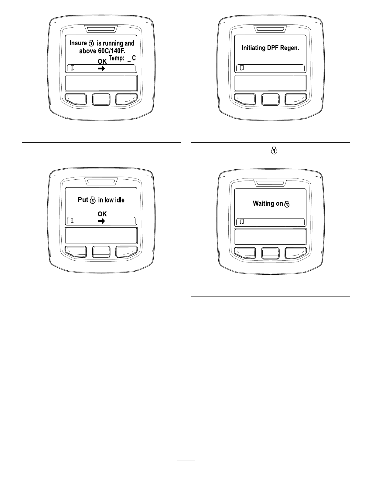
Figure36
g211986
g212405
Figure38
6.MovethethrottlecontroltoLOWIDLEandpress
thecenterbutton(Figure37).
Figure37
7.Thefollowingmessagesdisplayastheparked
regenerationprocessbegins:
A.The“InitiatingDPFRegen.”message
displays(Figure38).
B.The“Waitingon”messagedisplays
(Figure39).
g212372
Figure39
g212406
C.Thecomputerdetermineswhetherthe
regenerationruns.Oneofthefollowing
messagesdisplaysintheInfoCenter:
•Iftheregenerationisallowed,the
“RegenInitiated.Allowupto30minutes
forcompletion”messagedisplaysin
theInfoCenter,waitforthemachine
tocompletetheparkedregeneration
process(Figure40).
39

Figure40
•Iftheregenerationprocessisnot
allowedbytheenginecomputer,the
“DPFRegenNotAllowed”message
displaysintheInfoCenter(Figure41).
Presstheleftbuttontoexittothehome
screen
Important:Ifyoudidnotmeetallthe
requirementsforregenerationorif
lessthan50hourshavepassedsince
thelastregeneration,the“DPFRegen
NotAllowed”messageappears.
Theengineiscold—wait.
Theengineiswarm—wait.
Theenginehot—regenerationinprogress
(percentcomplete).
9.Theparkedregenerationiscompletewhenthe
“RegenComplete”messagedisplaysinthe
InfoCenter.Presstheleftbuttontoexittothe
g213424
homescreen(Figure42).
Figure41
8.Whiletheregenerationisrunning,theInfoCenter
returnstothehomescreenandshowsthe
followingicons:
g212404
Figure42
RecoveryRegeneration
•Ifyouignoretherequestforaparkedregeneration
(displayedintheInfoCenter)andcontinueto
operatethemachine,acriticalamountofsoot
buildsupintheDPF .
•Ifarecoveryregenerationisneeded,the
InfoCenterdisplaysenginewarningSPN3719,
FMI16(Figure43)andtheenginecomputer
g212410
deratesenginepowerto85%.
g213867
Figure43
Important:Ifyoudonotcompletearecovery
regenerationwithin15minutes,theengine
computerderatesenginepowerto50%.
40

•Performarecovery-regenerationwhenever
thereisalossofenginepowerandaparked
regenerationcannoteffectivelycleantheDPFof
soot.
•Arecoveryregenerationrequiresupto4hours
tocomplete.
•Youneedadistributortechniciantoperformthe
recoveryregenerationprocess;contactyour
AuthorizedT oroDistributor.
PushingorTowingthe
Machine
Important:Donotpushortowthemachine
fasterthan3to4.8km/h(2to3MPH)orinternal
transmissiondamagemayoccur.Thebypass
valvemustbeopenwheneverthemachineis
pushedortowed.
Important:Ifthemachinemustbepushedor
towedinreverse,thecheckvalveinthefour-wheel
drivemanifoldmustalsobebypassed.Tobypass
thecheckvalve,connectahoseassembly(Hose
PartNumber95-8843,CouplerFittingPartNumber
95-0985[Qty.2],andHydraulicFittingPart
Number340-77[Qty.2])tothereversetraction
pressuretestport,locatedonthehydrostat,and
ontheportlocatedin-betweenportsM8andP2
onthereartractionmanifoldwhichislocatedto
theinsideofthefrontreartire.
1.Openthehoodandlocatethebypassvalves
(Figure44)onthetopofpump,behindthe
battery/storageboxes.
2.Rotateeachvalve3turnscounter-clockwise
toopenandallowoiltobypassinternally.Do
notopenmorethan3turns.Becauseuidis
bypassed,themachinecanbeslowlymoved
withoutdamagingthetransmission.
g020510
Figure44
1.Bypassvalve(2)
3.Closethebypassvalvesbeforestartingthe
engine.T orqueto70N-m(52ft-lb)toclosethe
valve.
JackingPoints
•Front—frame,ontheinsideofeachdrivetire.
•Rear—centeroftheaxle.
TransportingtheMachine
Useaheavy-dutytrailerortrucktotransportthe
machine.Ensurethatthetrailerortruckhasall
necessarybrakes,lighting,andmarkingasrequired
bylaw.Pleasecarefullyreadallthesafetyinstructions.
Knowingthisinformationcouldhelpyou,yourfamily,
pets,orbystandersavoidinjury.
WARNING
Drivingonthestreetorroadwaywithoutturn
signals,lights,reectivemarkings,oraslow
movingvehicleemblemisdangerousandcan
leadtoaccidentscausingpersonalinjury.
Donotdrivemachineonapublicstreetor
roadway.
Totransportthemachine:
1.Ifusingatrailer,connectittothetowingvehicle
andconnectthesafetychains.
2.Ifapplicable,connectthetrailerbrakes.
3.Loadthemachineontothetrailerortruck.
41

4.Stoptheengine,removethekey,setthebrake,
andclosethefuelvalve.
5.Usethemetaltiedownloopsonthemachine
tosecurelyfastenthemachinetothetraileror
truckwithstraps,chains,cable,orropes.
LoadingtheMachine
Useextremecautionwhenloadingthemachineontoa
traileroratruck.1full-widthrampthatiswideenough
toextendbeyondthereartiresisrecommended
insteadofindividualrampsforeachsideofthe
machine(Figure45).Thelowerrearsectionof
themachineframeextendsbackbetweentherear
wheelsandservesasastopfortippingbackward.
Havingafull-widthrampprovidesasurfaceforthe
framememberstocontactifthemachinestartstotip
backward.Ifitisnotpossibletouseonefull-width
ramp,useenoughindividualrampstosimulatea
full-widthcontinuousramp.
Therampshouldbelongenoughsothattheangles
donotexceed15degrees(Figure45).Asteeper
anglemaycausemowercomponentstogetcaughtas
theunitmovesfromtheramptothetrailerortruck.
Steeperanglesmayalsocausethemachinetotip
backward.Ifloadingonornearaslope,positionthe
trailerortrucksothatitisonthedownsideofthe
slopeandtherampextendsuptheslope.Thiswill
minimizetherampangle.Thetrailerortruckshould
beaslevelaspossible.
WARNING
Loadingamachineontoatrailerortruck
increasesthepossibilityofbackwardtip-over
andcouldcauseseriousinjuryordeath.
•Useextremecautionwhenoperatinga
machineonaramp.
•EnsurethattheROPSisintheupposition
whileusingtheseatbeltwhenloadingthe
machine.EnsurethattheROPSwillclear
thetopofanenclosedtrailer.
•Useonlyasingle,full-widthramp;donot
useindividualrampsforeachsideofthe
machine.
•Ifindividualrampsmustbeused,use
enoughrampstocreateanunbrokenramp
surfacewiderthanthemachine.
•Donotexceeda15-degreeanglebetween
therampandthegroundorbetweenthe
rampandthetrailerortruck.
•Avoidsuddenaccelerationwhiledriving
themachineuparamp,toavoidtipping
backward.
•Avoidsuddendecelerationwhilebacking
themachinedownaramp,toavoidtipping
backward.
Important:Donotattempttoturnthemachine
whileontheramp;youmaylosecontrolanddrive
offtheside.
Avoidsuddenaccelerationwhendrivinguparamp
andsuddendecelerationwhenbackingdowna
ramp.Bothmaneuverscancausethemachinetotip
backward.
g000951
Figure45
1.Trailer3.Notgreaterthan
15degrees
2.Full-widthramp4.Full-widthramp—side
view
42

OperatingCharacteristics
Practicedrivingthemachinebecauseithasa
hydrostatictransmissionanditscharacteristicsare
differentthanmanyturfmaintenancemachines.
Somepointstoconsiderwhenoperatingthetraction
unitandcuttingunitsarethetransmission,engine
speed,loadonthecuttingbladesandtheimportance
ofthebrakes.
SelectingaBlade
StandardCombinationSail
Thisbladewasdesignedtoprovideexcellentliftand
dispersioninalmostanycondition.Ifmoreorlesslift
anddischargevelocityisrequired,consideradifferent
blade.
WithT oroSmartPower™,theoperatordoesnothave
tolistentotheenginespeedinheavyconditions.
SmartPowerpreventsboggingdowninheavyturf
byautomaticallycontrollingthemachinespeedand
optimizingcuttingperformance.
Anothercharacteristictoconsideristheoperation
ofthepedalsthatareconnectedtothebrakes.The
brakescanbeusedtoassistinturningthemachine.
However,usethemcarefully ,especiallyonsoftor
wetgrassbecausetheturfmaybetornaccidentally.
Anotherbenetofthebrakesistomaintaintraction.
Forexample,insomeslopeconditions,theuphill
wheelslipsandlosestraction.Ifthissituation
occurs,depresstheuphill-turnpedalgraduallyand
intermittentlyuntiltheuphillwheelstopsslipping,thus,
increasingtractiononthedownhillwheel.
Useextracarewhenoperatingthemachineon
slopes.Makesurethattheseatlatchisproperly
securedandtheseatbeltisbuckled.Driveslowly
andavoidsharpturnsonslopestopreventrollovers.
Forsteeringcontrol,thecuttingunitmustbelowered
whengoingdownhill.
Attributes:Excellentliftanddispersioninmost
conditions.
AngledSail
Thebladegenerallyperformsbestinlowerheightsof
cut–1.9to6.4cm(3/4to2–1/2inches).
Attributes:
•Dischargeremainsmoreevenatlowerheightsof
cut.
•Dischargehaslesstendencytothrowleftandthus
acleanerlookaroundbunkersandfairways.
•Lowerpowerrequirementatlowerheightsand
denseturf.
HighLiftParallelSail
Thebladegenerallyperformsbetterinthehigher
heightsofcut–7to10cm(2to4inches).
Attributes:
WARNING
Thisproductisdesignedtodriveobjectsinto
thegroundwheretheyloseenergyquickly
ingrassareas.However,carelessoperation,
combinedwithterrainangle,ricochets,or
improperlypositionedsafetyguardscanlead
tothrownobjectinjuries.
•Whenapersonorpetappearssuddenlyin
ornearthemowingarea,stopmowing.
•Donotresumemowinguntiltheareais
cleared.
Important:Allowenginetoidlefor5minutes
beforeshuttingitoffafterafullloadoperation.
Thisallowstheturbochargertocooldownbefore
shuttingtheengineoff.Failuretodosomaylead
toturbo-chargertrouble.
Beforestoppingtheengine,disengageallcontrols
andsettheenginespeedtoSlow.Settingtheengine
speedtoSlowreduceshighenginerpm,noise,and
vibration.TurnthekeyintheignitionswitchtotheOFF
positiontosoptheengine.
•Moreliftandhigherdischargevelocity.
•Sparseorlimpturfispickedupsignicantlyat
higherheightsofcut.
•Wetorstickyclippingsaredischargedmore
efcientlyreducingcongestioninthedeck.
•Requiresmorehorsepowertorun.
•Tendstodischargefurtherleftandcantendto
windrowatlowerheightsofcut.
WARNING
Donotusethehighliftbladewiththe
mulchingbafe.Thebladecouldbreak,
resultinginpersonalinjuryordeath.
AtomicBlade
Thisbladewasdesignedtoprovideexcellentleaf
mulching.
Attributes:Excellentleafmulching
43

ChoosingAccessories
OptionalEquipmentCongurations
AngleSailBladeHighLiftParallelSail
GrassCutting:1.9to4.4
cm(0.75to1.75inches)
heightofcut
GrassCutting:5to6.4
cm(2.00to2.50inches)
heightofcut
GrassCutting:7to10
cm(2.75to4.00inches)
heightofcut
LeafMulchingRecommendedforuse
ProsEvendischargeatlower
ConsDoesnotliftthegrass
Recommendedinmost
applications
Recommendedforthick
orlushturf
Mayworkwellinlushturf
withthemulchingbafe
heightofcut,cleaner
lookaroundbunkersand
fairways,lowerpower
requirements
wellinhighheight-of-cut
applications,wetor
stickygrasshasa
tendencytobuildupin
thechamber,leading
topoorqualityofcut
andhigherpower
requirements
Blade(Donotusewith
themulchingbafe)
Mayworkwellinlightor
sparseturf
Recommendedforlight
orsparseturf
Recommendedinmost
applications
NotAllowedUsewithcombination
Moreliftandhigher
dischargevelocity ,
sparseorlimpturfis
pickedupathighheight
ofcut,wetorsticky
clippingsaredischarged
efciently
Requiresmorepowerto
runinsomeapplications,
tendstowindrowat
lowerheightofcutin
lushgrass,donotuse
withthemulchingbafe
MulchingBafeRollerScraper
Hasbeenshownto
improvedispersionand
aftercutperformance
onnortherngrassesthat
arecutatleast3times
perweekandlessthan
1/3ofthegrassblade
isremoved.Donot
usewiththehighlift
parallelsailblade
sailoranglesailblade
only
Mayimprovedispersion
andappearancein
certaingrasscutting
applications,verygood
forleafmulching
Grasswillbuildupinthe
chamberifattemptingto
removetoomuchgrass
withbafeinplace
Canbeusedanytime
thatrollersbuildupwith
grassorlargeatgrass
clumpsofgrassare
seen.Thescrapers
mayactuallyincrease
clumpingincertain
applications.
Reducesrollerbuildup
incertainapplications
44

OperatingTips
WhentoMow
Moweitherinthelatemorningtoavoidthedew,which
causesgrassclumping,orinlateafternoontoavoid
thedamagethatcanbecausedbydirectsunlighton
thesensitive,freshlymowedgrass.
SelecttheProperHeight-of-Cut
SettingtoSuitConditions
Removeapproximately25mm(1inch)orno
morethan1/3ofthegrassbladewhencutting.In
exceptionallylushanddensegrass,youmayhaveto
raisetheheightofcuttothenextsetting.
MowatProperIntervals
Undermostnormalconditionsyouneedtomow
approximatelyevery4-5days.Butremember,grass
growsatdifferentratesatdifferenttimes.Thismeans
thatinordertomaintainthesameheightofcut,which
isagoodpractice,youwillneedtocutmorefrequently
inearlyspring;asthegrassgrowthrateslowsin
midsummer,cutonlyevery8-10days.Ifyouare
unabletomowforanextendedperiodduetoweather
conditionsorotherreasons,mowrstwiththeheight
ofcutatahighlevel;thenmowagain2-3dayslater
withalowerheightsetting.
AfterOperating
Toensurethatoptimumperformanceismet,clean
theundersideofthemowerhousingsaftereachuse.
Ifresidueisallowedtobuildupinthemowerhousing,
cuttingperformancedeclines.
Note:Lowercuttingunitstothegroundwhenever
machineisparked.Thisrelievesthehydraulicload
fromthesystem,preventswearonsystempartsand
alsopreventsaccidentalloweringofthecuttingunits.
AlwaysMowwithSharpBlades
Asharpbladecutscleanlyandwithouttearingor
shreddingthegrassbladeslikeadullblade.Tearing
andshreddingcausesthegrasstoturnbrownat
theedgeswhichimpairsgrowthandincreases
susceptibilitytodiseases.
MowingPatterns
Changemowingpatternsoftentominimizeaftercut
appearanceissuesinducedbyrepetitiveoperation
inonly1direction.
ResolvingAftercutAppearance
ReferenceAftercutAppearanceTroubleshooting
Guideavailableatwww.T oro.com.
Transporting(Groundsmaster
4700–DOnly)
Usethe2rear-transportlatchesfortheoutercutting
unitswhentransportingoverlongdistances,rough
terrain,orwhentrailering.
45

Maintenance
LookingforanElectricalSchematicorHydraulicSchematicforyourmachine?Downloadafreecopyofthe
schematicbyvisitingwww.Toro.comandsearchingforyourmachinefromtheManualslinkonthehomepage.
Important:RefertoyourEngineOperator'sManualandCuttingUnitOperator'sManualforadditional
maintenanceprocedures.
RecommendedMaintenanceSchedule(s)
MaintenanceService
Interval
Aftertherst8hours
Aftertherst200hours
Beforeeachuseordaily
Every50hours
Every100hours
Every200hours
Every250hours
MaintenanceProcedure
•Torquethewheelnuts.
•Changetheplanetarygeardriveoil.
•Changetherearaxlelubricant.
•Changethehydrauliclters.
•Checkthecoolingsystem.
•Checkthehydraulic-uidlevel.
•Checkthetirepressure.
•Checktheinterlockswitches.
•Checktheengine-oillevel.
•Drainwaterorothercontaminantsfromthewaterseparator.
•Drainwaterorothercontaminantsfromfuellter/waterseparator.
•Removedebrisfromtheenginearea,oilcooler ,andradiator.
•Inspectthehydrauliclinesandhosesforleaks,kinkedlines,loosemounting
supports,wear,loosettings,weatherdeterioration,andchemicaldeterioration.
•Checkthebladestoppingtime.
•Greasethebearingsandbushings.
•Checkthebatterycondition.
•Checktheconditionandtensionofthealternatorbelt.
•Torquethewheelnuts.
•Changetheengineoilandlter.
Every400hours
Every800hours
Every6,000hours
•Servicetheaircleaner.(Servicetheaircleanerearlieriftheair-cleanerindicator
showsred.Serviceitmorefrequentlyinextremelydirtyordustyconditions.)
•Checkthefuellinesandconnections.
•Replacetheenginefuellter.
•Replacethefuelltercanister.
•Checkforend-playintheplanetarydrives.
•Checktheplanetarygeardriveoillevel(Also,checkifexternalleakageisobserved).
•Checktherearaxlelubricantlevel.
•Drainandcleanthefueltank.
•Changetheplanetarygeardriveoil.(Oryearly,whichevercomesrst)
•Changetherearaxlelubricant.
•Checktherearwheeltoe-in.
•Changethehydraulicuid.
•Changethehydrauliclters.
•Disassemble,clean,andassemblethesootlteroftheDPF.orcleanthesoot
lterifenginefaultsSPN3720FMI16,SPN3720FMI0,orSPN3720FMI16display
intheInfoCenter.
46

MaintenanceService
Beforestorage
Interval
MaintenanceProcedure
•Drainandcleanthefueltank.
•Checkthetirepressure.
•Checkallfasteners.
•Greaseoroilallgreasettingsandpivotpoints.
•Paintchippedsurfaces.
Yearly
DailyMaintenanceChecklist
Duplicatethispageforroutineuse.
Maintenance
CheckItem
Checkthe
safetyinterlock
operation.
Checkthebrake
operation.
Checktheengine
oilandfuellevel.
Checkthe
coolingsystem
uidlevel.
Drainthe
water/fuel
separator.
Checktheair
lterrestriction
indicator.
Checkthe
radiator,oil
cooler,and
screenfordebris.
Checkunusual
enginenoises.
Checkunusual
operatingnoises.
Checkthe
hydraulicsystem
oillevel.
Checkhydraulic
hosesfor
damage.
Checkforuid
leaks.
Checkthetire
pressure.
Checkthe
instrument
operation.
Lubricateall
greasettings.
Fortheweekof:
Mon.Tues.Wed.Thurs.Fri.
1
2
•Checkthefuellinesandconnections.
Sat.Sun.
47

Maintenance
CheckItem
Checkthe
height-of-cut
adjustment.
Touch-up
damagedpaint.
Fortheweekof:
Mon.Tues.Wed.Thurs.Fri.
1.Checktheglowplugandinjectornozzlesifhardstarting,excesssmoke,orroughrunningisnoted.
2.Immediatelyaftereverywashing,regardlessoftheintervallisted.
ServiceIntervalChart
Sat.Sun.
Figure46
CAUTION
Ifyouleavethekeyintheignitionswitch,someonecouldaccidentlystarttheengineand
seriouslyinjureyouorotherbystanders.
Removethekeyfromtheignitionswitchbeforeyoudoanymaintenance.
48
decal125-4606

Pre-Maintenance
Procedures
Note:Determinetheleftandrightsidesofthe
machinefromthenormaloperatingposition.
RemovingtheHood
1.Releasethehoodlatches(Figure47)andpivot
thehoodopen.
Lubrication
GreasingtheBearingsand
Bushings
ServiceInterval:Every50hours
Themachinehasgreasettingsthatmustbe
lubricatedregularlywithNo.2lithiumgrease.
Thegreasettinglocationsandquantitiesareas
follows:
•Brake-shaftpivotbearings(5)(Figure48)
Figure47
1.Hoodlatch(2)
2.Removethecotterpinssecuringtherear-hood
bracketstotheframepinsandliftoffthehood.
g009704
Figure48
g009984
•Rear-axlepivotbushings(2)(Figure49)
g009705
Figure49
49

•Steering-cylinderballjoints(2)(Figure50)
•Cuttingunitspindle-shaftbearings(2percutting
unit)(Figure52)
Note:Eitherttingcanbeused,whicheveris
moreaccessible.Pumpgreaseintothettinguntil
asmallamountappearsatbottomofthespindle
housing(underthedeck).
Figure50
1.Topttingonkingpin
•Tie-rodballjoints(2)(Figure50)
•King-pinbushings(2)(Figure50).Thetoptting
onthekingpinshouldonlybelubricated
annually(2pumps).
•Lift-armbushings(1perdeck)(Figure51)
g009706
Figure52
g009708
•Cuttingunitcarrier-armbushings(1percutting
unit)(Figure52)
•Rear-rollerbearings(2percuttingunit)(Figure53)
g005979
Figure53
Important:Makesurethatthegreasegroove
ineachrollermountalignswiththegreasehole
ineachendoftherollershaft.Tohelpalign
thegrooveandhole,thereisalsoanalignment
markon1endoftherollershaft.
Figure51
•Lift-cylinderbushings(2perdeck)(Figure51)
g009707
50

EngineMaintenance
ServicingtheAirCleaner
ServiceInterval:Every400hours
3.Uselowpressureair(40psi,cleananddry)
tohelpremovelargeaccumulationsofdebris
packedbetweenoutsideofprimarylterand
thecanister.Avoidusinghighpressureair
whichcouldforcedirtthroughthelterinto
theintaketract.
Checktheair-cleanerbodyfordamagewhichcould
causeanairleak.Replaceifdamaged.Checkthe
wholeintakesystemforleaks,damage,orloosehose
clamps.
Servicetheair-cleanerlteronlywhentheservice
indicator(Figure54)requiresit.Changingtheairlter
beforeitisnecessaryonlyincreasesthechanceof
dirtenteringtheenginewhenthelterisremoved.
Figure54
1.Air-cleanerindicator
Note:Thiscleaningprocesspreventsdebris
frommigratingintotheintakewhentheprimary
lterisremoved.
4.Removeandreplacetheprimarylter(Figure
56).
Note:Itisnotrecommendedtocleantheused
lterduetopossiblydamagingtheltermedia.
5.Inspectthesealingendandbodyofthelter
forshippingdamage.Donotuseadamaged
element.
6.Insertanewlterandapplypressuretothe
outerrimtoseatitinthecanister.Donotapply
pressuretotheexiblecenterofthelter.
g009709
Important:Makesurethecoverisseated
correctlyandsealswiththeair-cleanerbody.
1.Pullthelatchoutwardandrotatetheair-cleaner
covercounterclockwise(Figure55).
Figure55
1.Air-cleanerlatch2.Air-cleanercover
g009711
Figure56
1.Air-cleanerprimarylter
Important:Neverattempttocleanthesafety
lter(Figure57).Replacethesafetylter
afterevery3primarylterservices.
g009710
2.Removethecoverfromtheaircleanerbody.
51
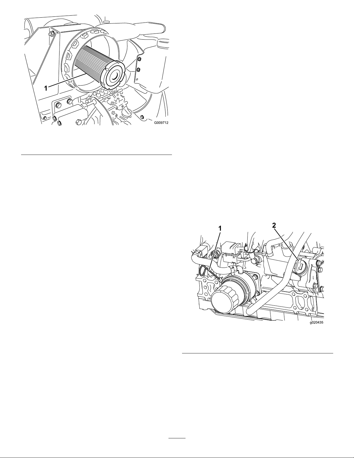
1.Air-cleanersafetylter
Figure57
Theengineisshippedwithoilinthecrankcase;
however,theoillevelmustbecheckedbeforeand
aftertheengineisrststarted.
Important:Checktheengineoildaily.Ifthe
engine-oillevelisabovetheFullmarkonthe
dipstick,theengineoilmaybedilutedwithfuel;
IftheengineoillevelisabovetheFullmark,
changetheengineoil.
Thebesttimetochecktheengineoiliswhenthe
engineiscoolbeforeithasbeenstartedfortheday.
Ifithasalreadybeenrun,allowtheoiltodrainback
downtothesumpforatleast10minutesbefore
checking.IftheoillevelisatorbelowtheAddmark
onthedipstick,addoiltobringtheoilleveltotheFull
g009712
mark.Donotoverlltheenginewithoil.
Important:Keeptheengineoillevelbetweenthe
upperandlowerlimitsonthedipstick;theengine
mayfailifyourunitwithtoomuchortoolittleoil.
7.Cleanthedirtejectionportlocatedinthe
removablecover.Tocleanthecavity,remove,
clean,andreplacetherubberoutletvalve.
8.Installthecoverorientingtherubberoutletvalve
inadownwardposition—betweenapproximately
5:00o’clockto7:00o’clockwhenviewedfrom
theend.
9.Resettheindicator(Figure54)ifitshowsred.
ServicingtheEngineOil
OilSpecication
Usehigh-quality,low-ashengineoilthatmeetsor
exceedsthefollowingspecications:
•APIservicecategoryCJ-4orhigher
•ACEAservicecategoryE6
•JASOservicecategoryDH-2
Important:UsingengineoilotherthanAPICJ-4
orhigher,ACEAE6,orJASODH-2maycausethe
dieselparticulateltertoplugorcauseengine
damage.
Usethefollowingengineoilviscositygrade:
•Preferredoil:SAE15W-40(above0°F)
•Alternateoil:SAE10W-30or5W-30(all
temperatures)
ToroPremiumEngineOilisavailablefromyour
AuthorizedT oroDistributorineither15W-40or
10W-30viscositygrades.Seethepartscatalogfor
partnumbers.
1.Parkthemachineonalevelsurface.
2.Unlocktheengine-coverlatchesandopenthe
enginecover.
3.Removethedipstick,wipeitclean,installthe
dipstickintothetube,andpullitoutagain.
Note:Theoillevelshouldbeinthesaferange
(Figure58).
Figure58
1.Dipstick
4.Iftheoilisbelowthesaferange,removethe
llcap(Figure58)andaddoiluntilthelevel
reachestheFullmark.Donotoverll.
2.Oil-llcap
Note:Whenusingdifferentoil,drainalloldoil
fromthecrankcasebeforeaddingnewoil.
g020435
CheckingtheEngine-OilLevel
ServiceInterval:Beforeeachuseordaily
5.Installtheoilllcapanddipstick.
6.Closetheenginecoverandsecureitwiththe
latches.
52

CrankcaseOilCapacity
Servicingthe
Approximately5.7L(6USqt)withthelter.
ChangingtheEngineOilandFilter
ServiceInterval:Every250hours
1.Removethedrainplug(Figure59)andlettheoil
owintoadrainpan.Whentheoilstops,install
thedrainplug.
Figure59
1.Oil-drainplug
Diesel-OxidationCatalyst
(DOC)andtheSootFilter
ServiceInterval:Every6,000hoursorcleanthesoot
lterifenginefaultsSPN3720FMI
16,SPN3720FMI0,orSPN3720FMI
16displayintheInfoCenter.
•IfadvisorymessageADVISORY179displaysinthe
InfoCenter,theDPFisnearingtherecommended
pointforservicingthediesel-oxidationcatalystand
thesootlter.
g213865
Figure61
g020434
•IfenginefaultsCHECKENGINESPN3251FMI0,
CHECKENGINESPN3720FMI0,orCHECKENGINE
SPN3720FMI16intheInfoCenter(Figure62)
displayintheInfoCenter,cleanthesootlterusing
thestepsthatfollow:
2.Removetheoillter(Figure60).
3.Applyalightcoatofcleanoiltothenewlter
sealbeforescrewingiton.Donotovertighten.
Figure60
1.Oillter
4.Addoiltothecrankcase;refertoCheckingthe
Engine-OilLevel(page52).
g214715
g213864
g213863
g020436
Figure62
1.RefertotheEnginesectionintheService
Manualforinformationondisassemblingand
assemblingthediesel-oxidationcatalystand
thesootlteroftheDPF .
2.RefertoyourAuthorizedT oroDistributorfor
diesel-oxidationcatalystandthesootlter
replacementpartsorservice.
3.ContactyourAuthorizedToroDistributorto
havethemresettheengineECUafteryou
installacleanDPF .
53

FuelSystem
ServicingtheFuelFilter
Maintenance
DANGER
Undercertainconditions,dieselfuelandfuel
vaporsarehighlyammableandexplosive.A
reorexplosionfromfuelcanburnyouand
othersandcancausepropertydamage.
•Useafunneltollthefueltankoutdoors,
inanopenarea,whentheengineisoffand
iscold.Wipeupanyfuelthatspills.
•Donotllthefueltankcompletelyfull.
Addfueltothefueltankuntilthelevelis6
to13mm(1/4to1/2inch)belowthebottom
ofthellerneck.Thisemptyspaceinthe
tankallowsthefueltoexpand.
•Neversmokewhenhandlingfuel,andstay
awayfromanopenameorwherefuel
fumesmaybeignitedbyaspark.
•Storefuelinaclean,safety-approved
containerandkeepthecapinplace.
ServiceInterval:Every400hours—Replacethe
enginefuellter.
1.Cleantheareaaroundthefuel-lterhead
(Figure63).
g021291
Figure63
1.Fuel-lterhead2.Fuellter
DrainingtheFuelTank
ServiceInterval:Every800hours—Drainandclean
thefueltank.
Beforestorage—Drainandcleanthefueltank.
Drainandcleanthetankiffuelsystembecomes
contaminatedorifthemachinewillbestoredforan
extendedperiodoftime.Usecleanfueltoushout
thetank.
CheckingtheFuelLines
andConnections
ServiceInterval:Every400hours
Yearly
Inspectthemfordeterioration,damage,orloose
connections.
2.Removethelterandcleanthelterhead
mountingsurface(Figure63).
3.Lubricatetheltergasketwithcleanlubricating
engineoil;refertotheEngineOperator's
Manual.
4.Installthedryltercanister,byhand,untilthe
gasketcontactsthelterhead,thenrotateitan
additional1/2turn.
5.Starttheengineandcheckforfuelleaksaround
thelterhead.
ServicingtheWater
Separator
ServiceInterval:Beforeeachuseordaily—Drain
waterorothercontaminantsfrom
fuellter/waterseparator.
Every400hours—Replacethefuellter
canister.
1.Placeacleancontainerunderthefuellter
(Figure64).
2.Loosenthedrainplugonthebottomofthelter
canisterandopentheventonthetopofthe
canistermount.
54

ElectricalSystem
Maintenance
ChargingandConnecting
theBattery
WARNING
Figure64
1.Waterseparatorltercanister
3.Cleantheareawheretheltercanistermounts.
4.Removetheltercanisterandcleanthe
mountingsurface.
5.Lubricatethegasketontheltercanisterwith
cleanoil.
6.Installtheltercanisterbyhanduntilthegasket
contactsmountingsurfaceandthenrotateitan
additional1/2turn.
7.Tightenthedrainplugonthebottomofthelter
canisterandclosetheventonthetopofthe
canistermount.
FuelPick-upTubeScreen
Thefuelpickuptube,locatedinsidethefueltank,is
equippedwithascreentohelppreventdebrisfrom
enteringthefuelsystem.Removefuelpickuptube
andcleanscreenasrequired.
g007367
Proposition65Warning
CALIFORNIA
Batteryposts,terminals,andrelated
accessoriescontainleadandlead
compounds,chemicalsknownto
theStateofCaliforniatocause
cancerandreproductiveharm.Wash
handsafterhandling.
1.Unlatchandraisetheoperator'sconsolepanel
(Figure65).
1.Operator'sconsolepanel
55
g009985
Figure65
2.Latch

DANGER
Batteryelectrolytecontainssulfuricacid
whichisadeadlypoisonandcauses
severeburns.
•Donotdrinkelectrolyteandavoid
contactwithskin,eyesorclothing.
Wearsafetyglassestoshieldyour
eyesandrubberglovestoprotect
yourhands.
•Fillthebatterywherecleanwateris
alwaysavailableforushingtheskin.
2.Connecta3to4Abatterychargertothebattery
posts.Chargethebatteryatarateof3to4Afor
4to8hours.
3.Whenthebatteryischarged,disconnectthe
chargerfromthepoweroutletandbatteryposts.
g009986
Figure66
1.Positivebatterycable2.Negativebatterycable
WARNING
Chargingthebatteryproducesgasses
thatcanexplode.
Neversmokenearthebatteryandkeep
sparksandamesawayfrombattery.
4.Installthepositivecable(red)tothepositive
(+)terminalandthenegativecable(black)to
thenegative(-)terminalofthebattery(Figure
66).Securecablestopostswithcapscrewsand
nuts.Makesurethatthepositive(+)terminal
isallofthewayontothepostandthecableis
positionedsnugtothebattery.Thecablemust
notcontactthebatterycover.Slidetherubber
bootoverthepositiveterminaltopreventa
possibleshortfromoccurring.
5.Securethecablestothepostswithcapscrews
andnuts.
Note:Makesurethatthepositive(+)terminal
isallofthewayontothepostandthecableis
positionedsnugtothebattery.Thecablemust
notcontactthebatterycover.
6.Slidetherubberbootoverthepositiveterminal
topreventapossibleshortfromoccurring.
WARNING
CALIFORNIA
Proposition65Warning
Batteryposts,terminals,andrelated
accessoriescontainleadandlead
compounds,chemicalsknownto
theStateofCaliforniatocause
cancerandreproductiveharm.Wash
handsafterhandling.
7.CoatbothbatteryconnectionswithGrafo
112X(skin-over)grease,PartNumber505-47,
petroleumjelly,orlightgreasetoprevent
corrosion.Slidetherubberbootoverthepositive
terminal.
8.Closetheconsolepanelandsecurethelatch.
56

WARNING
Batteryterminalsormetaltoolscould
shortagainstmetalcomponentscausing
sparks.Sparkscancausethebattery
gassestoexplode,resultinginpersonal
injury.
•Whenremovingorinstallingthe
battery,donotallowthebattery
terminalstotouchanymetalpartsof
themachine.
•Donotallowmetaltoolstoshort
betweenthebatteryterminalsand
metalpartsofthemachine.
Fuses
WARNING
Incorrectbatterycableroutingcould
damagethemachineandcablescausing
sparks.Sparkscancausethebattery
gassestoexplode,resultinginpersonal
injury.
•Alwaysdisconnectthenegative
(black)batterycablebefore
disconnectingthepositive(red)
cable.
•Alwaysconnectthepositive(red)
batterycablebeforeconnectingthe
negative(black)cable.
BatteryCare
ServiceInterval:Every50hours—Checkthebattery
condition.
Important:Beforeweldingonthemachine,
disconnectthenegative(black)cablefromthe
batterytopreventdamagetotheelectricalsystem.
decal125-4605
Figure67
Unhookthelatchandraisetheoperator'sconsole
panel(Figure68)toexposethefuses(Figure69).
Note:Keeptheterminalsandtheentirebattery
casecleantoavoidslowdischarge.Tocleanthe
battery,removeitfromthemachineandwashthe
entirecasewithasolutionofbakingsodaandwater.
Rinsewithclearwater.Coatthebatterypostsand
cableconnectorswithGrafo112X(skin-over)grease
(ParNumber505-47)orpetroleumjellytoprevent
corrosion.
g009985
Figure68
1.Latch
57
2.Operator'sconsolepanel

DriveSystem
Maintenance
CheckingforEnd-Playin
thePlanetaryDrives
ServiceInterval:Every400hours
Thereshouldbenoend-playintheplanetary
drives/drivewheels(i.e.,thewheelsshouldnotmove
whenyoupullorpushtheminadirectionparallelto
theaxle).
1.Parkthemachineonalevelsurface,engagethe
g010255
Figure69
1.Fuses
parkingbrake,lowerthecuttingunits,shutoff
theengine,andremovethekey.
2.Chocktherearwheelsandraisethefrontof
machine,supportingthefrontaxle/frameonjack
stands.
DANGER
Amachineonajackmaybeunstableand
slipoffthejack,injuringanyonebeneath
it.
•Donotstarttheenginewhilethe
machineisonajack.
•Alwaysremovethekeyfromthe
switchbeforegettingoffthemachine.
•Blockthetireswhenyouareraising
themachinewithajack.
•Supportthemachinewithjackstands.
3.Grasp1ofthefrontdrivewheelsandpush/pullit
towardandawayfromthemachine,notingany
movement.
g028798
Figure70
1.Frontdrivewheels
4.Repeatstep3fortheotherdrivewheel.
5.Ifeitherwheelmoves,contactyourauthorized
Torodistributortohavetheplanetarydrive
rebuilt.
58

CheckingtheTorqueofthe
ChangingthePlanetary
WheelNuts
ServiceInterval:Aftertherst8hours
Every200hours
WARNING
Failuretomaintainpropertorqueofthewheel
nutscouldresultinfailureorlossofwheel
andmayresultinpersonalinjury.
Torquethefrontandrearwheelnutsto115
to136N-m(85-100ft-lb)after1to4hoursof
operationandagainafter8hoursofoperation.
Torqueevery200hoursthereafter.
Note:Frontwheelnutsare1/2-20UNF.Rearwheel
nutsareM12x1.6-6H(Metric).
CheckingthePlanetary
GearDriveOil
ServiceInterval:Every400hours
UsehighqualitySAE85W-140gearlubeasa
replacement.
1.Positionthemachineonalevelsurfaceand
positionthewheelso1checkplug(Figure71)
isatthe12o'clockpositionandtheotherisat
3o'clockposition.
GearDriveOil
ServiceInterval:Aftertherst200hours
Every800hours(Oryearly ,whichevercomes
rst)
UseahighqualitySAE85W-140gearlubeas
replacement.
1.Positionthemachineonalevelsurfaceand
positionawheelsothat1ofthecheckplugsis
atthelowest(6o'clock)position(Figure72).
g008862
Figure72
1.Check/drainplug
2.Placeadrainpanundertheplanetaryhub,
removetheplug,andallowtheoiltodrain.
3.Placeadrainpanunderthebrakehousing,
removethedrainplug,andallowtheoiltodrain
(Figure73).
Figure71
1.Check/drainplug(2)
2.Removetheplugatthe3o’clockposition(Figure
71).
Note:Theoillevelshouldbeatthebottomof
thecheck-plughole.
3.Iftheoillevelislow,removetheplugatthe12
o’clockpositionandaddoiluntilitbeginstoow
outoftheholeatthe3o’clockposition.
4.Installbothplugs.
5.Repeatsteps1through4ontheopposite
planetarygearassembly.
g019500
g019743
Figure73
1.Brakehousing2.Drainplug
4.Whenalloftheoilhasdrainedfromboth
locations,installthepluginthebrakehousing.
5.Rotatethewheeluntiltheopenplughole,inthe
planetary,isatthetwelveo'clockposition.
59
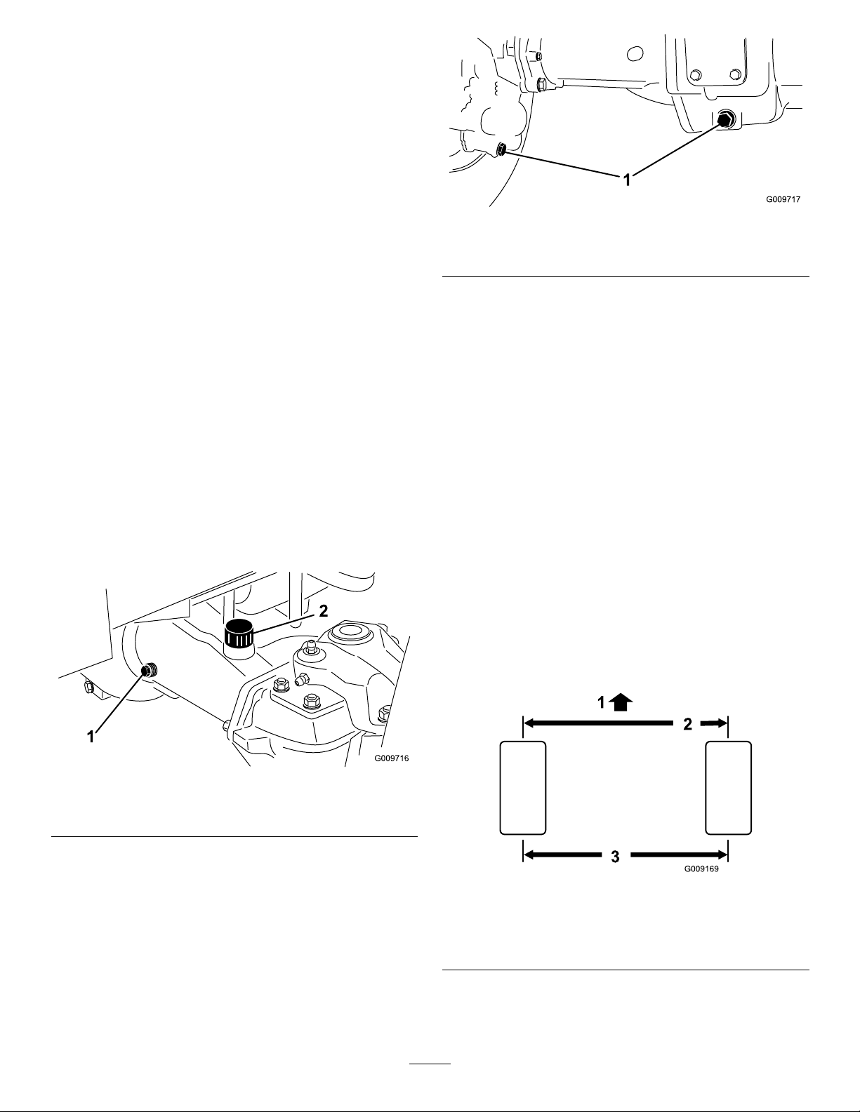
6.Throughtheopenhole,slowlylltheplanetary
with0.65L(22oz)ofhighqualitySAE85W-140
gearlube.
Important:Iftheplanetaryllsbeforethe
0.65L(22oz)ofoilisadded,wait1hour
orinstalltheplugandmovethemachine
approximately3m(10ft)todistributetheoil
throughthebrakesystem.Then,removethe
plugandaddtheremainingoil.
7.Installtheplug.
8.Repeattheprocedureontheopposite
planetary/brakeassembly.
g009717
Figure75
1.Drain-pluglocation
CheckingtheRearAxle
Lubricant
ServiceInterval:Every400hours
Therearaxleisshippedfromthefactorylledwith
SAE85W-140gearlube.Thecapacityis2.4L(80
oz).Visuallyinspectforleaksdaily.
1.Positionthemachineonalevelsurface.
2.Removeacheckplugfrom1endoftheaxle
(Figure74)andmakesurethatthelubricantis
uptothebottomofthehole.
3.Ifthelevelislow,removethellplug(Figure
74)andaddenoughlubricanttobringthelevel
uptothebottomofthecheckplugholes.
3.Removethe3oil-levelcheckplugsandmain
axleventcaptoeaseindrainingoftheoil.
4.Removethedrainplugsandallowtheoiltodrain
intothepans.
5.Installtheplugs.
6.Removeacheckplugandllaxlewith
approximately2.4L(80oz)of85W-140gear
lubeoruntillubricantreachesthebottomofthe
hole.
7.Installthecheckplug.
CheckingtheRearWheel
Toe-In
ServiceInterval:Every800hours/Yearly(whichever
comesrst)
1.Measurethecenter-to-centerdistance(ataxle
height)atthefrontandrearofthesteeringtires.
Thefrontmeasurementmustbe3mm(1/8inch)
lessthantherearmeasurement(Figure76).
Figure74
1.Checkplug
2.Fillplug
ChangingtheRearAxle
Lubricant
ServiceInterval:Aftertherst200hours
Every800hours
1.Positionthemachineonalevelsurface.
2.Cleantheareaaroundthe3drainplugs,1on
eachendand1inthecenter(Figure75).
g009716
g009169
Figure76
1.Frontoftractionunit3.Centertocenterdistance
2.1/8inchlessthanrearof
tire
2.Toadjust,removethecotterpinandnutfrom
eithertie-rodballjoint(Figure77)andremove
thetie-rodballjointfromtheaxle-casesupport.
60

CoolingSystem
Maintenance
ServicingtheEngine
CoolingSystem
Figure77
1.Tie-rodclamp2.Tie-rodballjoint
3.Loosentheclampsatbothendsofthetierods
(Figure77).
4.Rotatethedetachedballjointinwardoroutward
1completerevolutionandtightentheclampat
thelooseendofthetierod.
5.Rotatetheentiretie-rodassemblythesame
direction(inwardoroutward)1complete
revolutionandtightentheclampatthe
connectedendofthetierod.
6.Installtheballjointintheaxle-casesupport,
tightenthenutnger-tight,andmeasurethe
toe-in.
7.Repeatprocedureifnecessary.
8.Tightenthenutandinstallanewcotterpinwhen
theadjustmentiscorrect.
g009718
ServiceInterval:Beforeeachuseordaily
Cleanthemmorefrequentlyindirtyconditions.
Thismachineisequippedwithahydraulicallydriven
fandrivesystemthatautomatically(ormanually)
reversestoreduceoilcooler/radiatorandscreen
debrisbuildup.Whilethisfeaturecanhelpreduce
thetimerequiredtocleanoilcooler/radiator,itdoes
noteliminatetheneedforroutinecleaning.Periodic
cleaningandinspectionoftheradiator/coolerisstill
required.
1.Unlatchandswingopentherearscreen(Figure
78).
2.Cleanthescreenthoroughlyofalldebris.
Note:T oremovescreen,liftoffhingepins.
Figure78
1.Rear-screenlatch
3.Thoroughlycleanbothsidesoftheoilcooler
andtheradiator(Figure79)withcompressed
air.Startfromthefrontandblowthedebris
outtowardstheback.Thencleanfromthe
backsideandblowtowardsthefront.Repeat
procedureseveraltimesuntilallchaffanddebris
isremoved.
61
g009988

BrakeMaintenance
AdjustingtheService
Brakes
Adjusttheservicebrakeswhenthereismorethan
25mm(1inch)offreetravelofthebrakepedalor
whenthebrakesdonotworkeffectively.Freetravel
isthedistancethebrakepedalmovesbeforebraking
resistanceisfelt.
1.Disengagethelockinglatchfromthebrake
pedalssothatbothpedalsworkindependently
ofeachother.
2.Toreducefreetravelofthebrakepedals,tighten
thebrakes:
A.Loosenthefrontnutonthethreadedendof
g020509
Figure79
1.Oilcooler/radiator
thebrakecable(Figure80).
Important:Cleaningtheoilcooler/radiator
withwaterpromotesprematurecorrosion
damagetocomponentsandcompacts
debris.
4.Closetherearscreenandsecureitwiththe
latch.
g009721
Figure80
1.Brakecable
B.Tightentherearnuttomovethecable
backwarduntilthebrakepedalshave13to
25mm(1/2to1inch)offreetravel.
C.Tightenthefrontnutsafterthebrakesare
adjustedcorrectly.
62
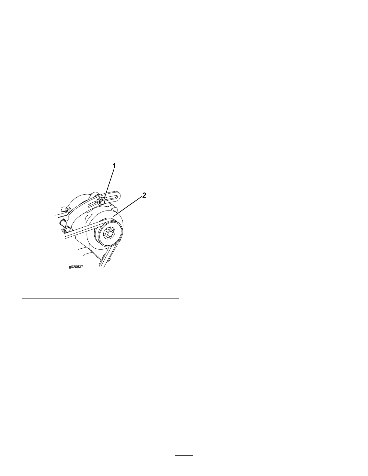
BeltMaintenance
ServicingtheAlternator
HydraulicSystem
Maintenance
Belt
ServiceInterval:Every100hours—Checkthe
conditionandtensionofthe
alternatorbelt.
Note:Thebeltshoulddeect10mm(3/8inch).Ifthe
deectionisincorrect,proceedtostep2.Ifcorrect,
continueoperation.
1.Loosenthealternatormountingbolts(Figure
81).
2.Increaseordecreasethealternatorbelttension,
tightenthebolts,andcheckthedeectionofthe
beltagaintoensurethatthetensioniscorrect.
ChangingtheHydraulic
Fluid
ServiceInterval:Every800hours
Iftheuidbecomescontaminated,contactyourT oro
Distributorbecausethesystemmustbeushed.
Contaminateduidlooksmilkyorblackwhen
comparedtocleanoil.
1.TurnthekeyintheignitionswitchtotheOFF
positionandraisethehood.
2.Disconnectthehosefromthebottomofthe
reservoirandletthehydraulicuidowintoa
largedrainpan.
3.Installthehosewhenhydraulicuidstop
draining.
4.Fillthereservoirwithapproximately28.4L(7.50
USgallons)ofhydraulicuid;refertoChecking
theHydraulic-FluidLevel(page29).
Important:Useonlythehydraulicuids
specied.Otheruidscouldcausesystem
damage.
1.Mountingbolt2.Alternator
Figure81
5.Installthereservoircap.
6.Starttheengine,useallofthehydrauliccontrols
todistributehydraulicuidthroughoutthe
system,andcheckforleaks.
g020537
7.TurnthekeyintheignitionswitchtotheOFF
position.
8.Checktheuidlevelandaddenoughtoraise
leveltheleveltotheFullmarkonthedipstick.
Donotoverll.
ReplacingtheHydraulic
Filters
ServiceInterval:Aftertherst200hours
Every800hours
UseT ororeplacementltersPartNumber94-2621for
therear(cuttingunit)ofthemachineandPartNumber
75-1310forthefront(charge)ofthemachine.
Important:Theuseofanyotherltermayvoid
thewarrantyonsomecomponents.
1.Positionthemachineonalevelsurface,lower
thecuttingunits,turnthekeyintheignition
switchtotheOFFposition,engagetheparking
brakes,andremovethekey.
63

2.Cleantheareaaroundtheltermountingarea.
Placeadrainpanunderthelterandremove
thelter(Figure82andFigure83).
7.TurnthekeyintheignitionswitchtotheOFF
positionandcheckforleaks.
3.Lubricatethegasketonthenewlterandllthe
lterwithhydraulicuid.
Figure82
1.Hydrauliclter
CheckingtheHydraulic
LinesandHoses
ServiceInterval:Beforeeachuseordaily
Inspectthehydrauliclinesandhosesforleaks,kinked
lines,loosemountingsupports,wear,loosettings,
weatherdeterioration,andchemicaldeterioration.
Makeallnecessaryrepairsbeforeoperating.
WARNING
Hydraulicuidescapingunderpressurecan
penetrateskinandcauseinjury .
•Makesurethatallhydraulic-uidhoses
andlinesareingoodconditionandall
hydraulicconnectionsandttingsaretight
g009723
beforeapplyingpressuretothehydraulic
system.
•Keepyourbodyandhandsawayfrom
pin-holeleaksornozzlesthateject
high-pressurehydraulicuid.
Figure83
1.Hydrauliclter
4.Ensurethattheltermountingareaisclean.
•Usecardboardorpapertondhydraulic
leaks.
•Safelyrelieveallpressureinthehydraulic
systembeforeperforminganyworkonthe
hydraulicsystem.
•Seekimmediatemedicalattentionifuid
isinjectedintoskin.
g009989
5.Screwthelterbyhanduntilthegasketcontacts
themountingplateandthentightenthelteran
additional1/2turn.
6.Starttheengineandletitrunforabout2minutes
topurgeairfromthesystem.
64

CuttingDeck
MountingtheCuttingDecks
Maintenance
SeparatingtheCutting
DecksfromtheTraction
Unit
1.Positionthemachineonalevelsurface,lower
thecuttingdeckstotheoor,turnthekeyinthe
ignitionswitchtotheOFFposition,andengage
theparkingbrake.
2.Disconnectandremovethehydraulicmotor
fromthedeck(Figure84).Coverthetopofthe
spindletopreventcontamination.
totheTractionUnit
1.Positionthemachineonalevelsurfaceandturn
thekeyintheignitionswitchtotheOFFposition.
2.Movethecuttingdeckintopositioninfrontof
thetractionunit.
3.Slidethedeckcarrierframeontothelift-arm
pivotpin.Securewithlynchpinorretainingnut
(GM4700only)(Figure85).
4.Installthehydraulicmotortothedeck(Figure
84).MakesurethattheO-ringisinpositionand
notdamaged.
5.Greasethespindle.
ServicingtheBladePlane
Therotarydeckcomesfromthefactorypresetat5
cm(2inches)heightofcutandbladerakeof7.9mm
(0.310inch).Theleftandrightheightsarealsopreset
towithin±0.7mm(0.030inch)oftheother.
Thecuttingdeckisdesignedtowithstandblade
impactswithoutdeformationofthechamber.Ifasolid
objectisstruck,inspectthebladefordamageandthe
bladeplaneforaccuracy.
Figure84
1.Motor-mountingscrews
3.Removethelynchpinorretainingnut(GM4700
only)securingthedeckcarrierframetothe
lift-armpivotpin(Figure85).
Figure85
g011351
g011352
InspectingtheBladePlane
1.Removethehydraulicmotorfromthecutting
deckandremovethecuttingdeckfromthe
tractor.
2.Useahoist(orminimumof2people)andplace
thecuttingdeckonaattable
3.Mark1endofthebladewithapaintpenor
marker.Usethisendofthebladetocheckall
heights.
4.Positionthecuttingedgeofthemarkedendof
thebladeat12o’clock(straightaheadinthe
directionofmowing)(Figure86)andmeasure
heightfromtabletocuttingedgeofblade.
1.Lynchpin
4.Rollthecuttingdeckawayfromthetractionunit.
2.Lift-armpivotpin
g011353
Figure86
65

5.Rotatethemarkedendofthebladetothe3and
9o’clockpositions(Figure86)andmeasurethe
heights.
adjustmentisneededforthatside.Adjustthe
othersidetowithin±2.2mm(0.090inch)ofthe
correctside.
6.Comparethe12o’clockmeasuredheighttothe
height-of-cutsetting.Itshouldbewithin0.7mm
(0.030inch).The3and9o’clockheightsshould
be3.8±2.2mm(0.150±.090inch)higherthan
the12o’clocksettingandwithin2.2mm(0.090
inch)ofeachother.
Ifanyofthesemeasurementsarenotwithin
specication,proceedtoAdjustingtheBladePlane.
AdjustingtheBladePlane
Startwiththefrontadjustment(change1bracketata
time).
1.Removetheheight-of-cutbracket,(front,left,or
right)fromthedeckframe(Figure87).
2.Adjust1.5mm(0.060inch)shimsand/or0.7mm
(0.030inch)shimbetweenthedeckframeand
brackettoachievethedesiredheightsetting
(Figure87).
7.Adjusttherightand/orleftheight-of-cutbrackets
byrepeatingsteps1through3.
8.Securethecarriageboltsandangenuts.
9.Again,verifythe12,3,and9o’clockheights.
ServicingtheCutterBlade
RemovingtheCutterBlade
Theblademustbereplacedifasolidobjectishit,
thebladeisoutofbalance,orifthebladeisbent.
AlwaysusegenuineT ororeplacementbladestobe
sureofsafetyandoptimumperformance.Neveruse
replacementbladesmadebyothermanufacturers
becausetheycouldbedangerous.
1.Raisethecuttingdecktothehighestposition,
shuttheengineoff,andengagetheparking
brake.Blockthecuttingdecktopreventitfrom
fallingaccidentally.
2.Grasptheendofthebladeusingaragorthickly
paddedglove.Removethebladebolt,anti-scalp
cup,andbladefromthespindleshaft(Figure
88).
Figure87
1.Height-of-cutbracket2.Shims
3.Installtheheight-of-cutbrackettothedeck
framewiththeremainingshimsassembled
belowtheheight-of-cutbracket.
4.Securethesocket-headbolt/spacerandange
nut.
Note:Socket-headbolt/spacerareheld
togetherwiththread-lockingadhesivetoprevent
thespacerfromfallinginsidethedeckframe.
5.Verifythe12o’clockheightandadjustifneeded.
6.Determineifonly1orboth(rightandleft)
height-of-cutbracketsneedtobeadjusted.Ifthe
3or9o’clocksideis3.8±2.2mm(0.150±0.090
inch)higherthanthenewfrontheightthenno
g011354
g011355
Figure88
1.Bladebolt2.Anti-scalpcup
3.Installtheblade,sailfacingtowardthecutting
deck,withtheanti-scalpcupandbladebolt
(Figure88).T orquethebladeboltto115to149
N-m(85to110ft-lb).
66

DANGER
Awornordamagedbladecanbreak,
andapieceofthebladecouldbethrown
intotheoperator’sorbystander’sarea,
resultinginseriouspersonalinjuryor
death
•Inspectthebladeperiodicallyforwear
ordamage.
•Neverweldabrokenorcrackedblade.
•Alwaysreplaceawornordamaged
blade.
InspectingandSharpeningthe
Blade
1.Raisethecuttingdecktothehighestposition,
turnthekeyintheignitionswitchtotheOFF
position,andengagetheparkingbrake.
2.Blockthecuttingdecktopreventitfromfalling
accidentally.
3.Examinethecuttingendsofthebladecarefully ,
especiallywheretheatandcurvedpartsofthe
blademeet(Figure89).
4.Sincesandandabrasivematerialcanwear
awaythemetalthatconnectstheatandcurved
partsoftheblade,checkthebladebeforeusing
themachine.Ifwearisnoticed(Figure89),
replacetheblade;refertoRemovingtheCutter
Blade(page66).
g006924
Figure89
1.Cuttingedge3.Wear/slot/crack
2.Sail
5.Inspectthecuttingedgesofallblades.Sharpen
thecuttingedgesiftheyaredullornicked.
Sharpenonlythetopofthecuttingedgeand
maintaintheoriginalcuttingangletomakesure
ofsharpness(Figure90).
Note:Thebladewillremainbalancedifthe
sameamountofmetalisremovedfromboth
cuttingedges.
g006926
Figure90
1.Sharpenatthisangleonly
DANGER
Ifthebladeisallowedtowear,aslot
willformbetweenthesailandatpart
oftheblade(Figure89).Eventuallya
pieceoftheblademaybreakoffandbe
thrownfromunderthehousing,possibly
resultinginseriousinjurytoyourselfor
bystanders.
•Inspectthebladeperiodicallyforwear
ordamage.
•Alwaysreplaceawornordamaged
blade.
6.Tocheckifthebladeisstraightandparallel,lay
thebladeonalevelsurfaceandcheckitsends.
Note:Theendsoftheblademustbeslightly
lowerthanthecenter,andthecuttingedgemust
belowerthantheheeloftheblade.Thisblade
willproducegoodqualityofcutandrequire
minimalpowerfromtheengine.Bycontrasta
bladethatishigherattheendsthanthecenter,
orifcuttingedgeishigherthantheheel,the
bladeisbentorwarpedandmustbereplaced.
7.Installtheblade,sailfacingtowardcuttingdeck,
withtheanti-scalpcupandbladebolt.T orque
thebladeboltto115to149N-m(85to110ft-lb).
CheckingtheBladeStoppingTime
ServiceInterval:Beforeeachuseordaily
Thebladesofthecuttingdeckshouldcometoa
completestopinapproximately5secondsafteryou
shutdownthecutting-deck-engagementswitch.
67

Note:Makesurethedecksareloweredontoaclean
sectionofturforhardsurfacetoavoidthrowndust
anddebris.
1.Haveasecondpersonstandbackfromthedeck
atleast6m(20ft)andwatchthebladeson1of
thecuttingdecks.
2.Shutthecuttingdecksdownandrecordthetime
ittakesforthebladestocometoacomplete
stop.
Note:Ifthistimeisgreaterthan7seconds,
thebrakingvalveneedsadjustment.Callyour
ToroDistributorforassistanceinmakingthis
adjustment
Toverifythisstoppingtime,haveasecondperson
standbackfromthedeckatleast6m(20feet)and
watchthebladesononeofthecuttingdecks.Have
theoperatorshutthecuttingdecksdownandrecord
thetimeittakesforthebladestocometoacomplete
stop.Ifthistimeisgreaterthan7seconds,thebraking
valveneedsadjustment.CallyourT oroDistributorfor
assistanceinmakingthisadjustment.
3.Pushthesecondbearingoutinpress.
4.Inspecttherollerhousing,bearings,andbearing
spacerfordamage(Figure91).Replace
damagedcomponentsandassemble.
AssemblingtheFrontRoller
1.Presstherstbearingintotherollerhousing
(Figure91).Pressontheouterraceonlyor
equallyontheinnerandouterrace.
2.Insertthespacer(Figure91).
3.Pressthesecondbearingintotherollerhousing
(Figure91)bypressingequallyontheinnerand
outerraceuntiltheinnerracecomesincontact
withthespacer.
4.Installtherollerassemblyintothedeckframe.
5.Verifythatthereisnomorethana1.5mm(0.060
inch)gapbetweenrollerassemblyandtheroller
mountbracketsofthedeckframe.Ifthereisa
gapover1.5mm(0.060inch),installenough5/8
inchdiameterwasherstotakeuptheslop.
ServicingtheFrontRoller
Inspectthefrontrollerforwear,excesswobble,or
binding.Serviceorreplacetherollerorcomponentsif
anyoftheseconditionsexist.
DisassemblingtheFrontRoller
1.Removetherollermountingbolt(Figure91).
2.Insertapunchthroughtheendoftheroller
housinganddrivetheoppositebearingoutby
alternatingtapstotheoppositesideofinner
bearingrace.
Note:Thereshouldbea1.5mm(0.060inch)
lipofinnerraceexposed.
Important:Securingtherollerassembly
withagaplargerthan1.5mm(0.060inch)
createsasideloadonthebearingandcan
leadtoprematurebearingfailure
6.Torquethemountingboltto108N-m(80ft-lb).
Figure91
1.Frontroller3.Bearing
2.Mountingbolt4.Bearingspacer
g011356
68

Storage
anti-freezeasneededfortheexpectedminimum
temperatureinyourarea.
PreparingtheTractionUnit
1.Thoroughlycleanthetractionunit,cuttingunits,
andtheengine.
2.Checkthetirepressure;refertoCheckingthe
TirePressure(page29).
3.Checkallfastenersforloosenessandtighten
themasnecessary.
4.Greaseallgreasettingsandpivotpoints.Wipe
upanyexcesslubricant.
5.Lightlysandandusetouch-uppaintonpainted
areasthatarescratched,chipped,orrusted.
Repairanydentsinthemetalbody.
6.Servicethebatteryandcablesasfollows:
A.Removethebatteryterminalsfromthe
batteryposts.
B.Cleanthebattery,terminals,andpostswith
awirebrushandbakingsodasolution.
C.Coatthecableterminalsandbatteryposts
withGrafo1 12Xskin-overgrease(Part
Number505-47)orpetroleumjellyto
preventcorrosion.
CuttingDeck
Ifthecuttingdeckisseparatedfromthetractionunit
foranylengthoftime,installaspindlepluginthetopof
thespindletoprotectthespindlefromdustandwater.
D.Slowlyrechargethebatteryevery60days
for24hourstopreventleadsulfationofthe
battery.
7.Engagethetransportlatches(Groundsmaster
4700–Donly).
PreparingtheEngine
1.Draintheengineoilfromtheoilpanandinstall
thedrainplug.
2.Removeanddiscardtheoillter.Installanew
oillter.
3.Relltheoilpanwith5.7L(6USqt)ofSAE
15W-40CH-4,CI-4,highermotoroil.
4.Starttheengineandrunitatidlespeedfor
approximately2minutes.
5.Stoptheengine.
6.Flushthefueltankwithfresh,cleandieselfuel.
7.Secureallofthefuelsystemttings.
8.Thoroughlycleanandservicetheaircleaner
assembly.
9.Sealtheaircleanerinletandtheexhaustoutlet
withweatherprooftape.
10.Checktheantifreezeprotectionandadda
50/50solutionofwaterandethyleneglycol
69

Notes:

InternationalDistributorList
Distributor:
AgrolancKft
AsianAmericanIndustrial(AAI)
B-RayCorporation
BrisaGoodsLLC
CascoSalesCompany
CeresS.A.CostaRica
CSSCTurfEquipment(pvt)Ltd.SriLanka
CyrilJohnston&Co.
CyrilJohnston&Co.RepublicofIreland
FatDragon
FemcoS.A.Guatemala
FIVEMANSNew-T echCo.,LtdChina
ForGarderOU
G.Y .K.CompanyLtd.
GeomechanikiofAthensGreece
GolfinternationalTurizm
HakoGroundandGardenSweden
HakoGroundandGarden
HayterLimited(U.K.)
HydroturfInt.CoDubai
HydroturfEgyptLLC
IrrimacPortugal351212388260ToroEuropeNVBelgium3214562960
IrrigationProductsInt'lPvtLtd.India00914424494387V altechMorocco212537663636
JeanHeybroekb.v.Netherlands31306394611VictusEmakPoland48618238369
Country:
Hungary3627539640
HongKong85224977804
Korea82325512076
Mexico12104952417
PuertoRico7877888383
NorthernIreland442890813121
China
Estonia3723846060
Japan81726325861Riversa
Turkey902163365993
Norway4722907760
UnitedKingdom441279723444
UnitedArabEmirates97143479479T-MarktLogisticsLtd.Hungary3626525500
Egypt2025194308ToroAustraliaAustralia61395807355
PhoneNumber:Distributor:
MaquiverS.A.Colombia
MaruyamaMfg.Co.Inc.
Mountelda.s.CzechRepublic
Mountelda.s.Slovakia
5062391138
94112746100
442890813121ParklandProductsLtd.NewZealand6433493760
8861080841322
5024423277
86-10-63816136
30109350054
4635100000
MunditolS.A.
NormaGarden
OslingerTurfEquipmentSA
OyHakoGroundandGardenAb
Perfetto
PratoverdeSRL.
Prochaska&Cie
RTCohen2004Ltd.
LelyTurfcare
Lely(U.K.)Limited
SolvertS.A.S.
SpyprosStavrinidesLimitedCyprus
SurgeSystemsIndiaLimited
Country:
Japan81332522285
Argentina541 148219999
Russia74954116120
Ecuador59342396970
Finland35898700733
Poland48618208416
Italy390499128128
Austria4312785100
Israel97298617979
Spain
Denmark4566109200
UnitedKingdom441480226800
France33130817700
India911292299901
PhoneNumber:
5712364079
420255704220
420255704220
34952837500
35722434131
EuropeanPrivacyNotice
TheInformationT oroCollects
ToroWarrantyCompany(T oro)respectsyourprivacy.Inordertoprocessyourwarrantyclaimandcontactyouintheeventofaproductrecall,weaskyou
tosharecertainpersonalinformationwithus,eitherdirectlyorthroughyourlocalT orocompanyordealer.
TheT orowarrantysystemishostedonserverslocatedwithintheUnitedStateswhereprivacylawmaynotprovidethesameprotectionasapplies
inyourcountry.
BYSHARINGYOURPERSONALINFORMATIONWITHUS,YOUARECONSENTINGTOTHEPROCESSINGOFYOURPERSONALINFORMATION
ASDESCRIBEDINTHISPRIV ACYNOTICE.
TheWayT oroUsesInformation
Toromayuseyourpersonalinformationtoprocesswarrantyclaims,tocontactyouintheeventofaproductrecallandforanyotherpurposewhichwetell
youabout.ToromayshareyourinformationwithT oro'safliates,dealersorotherbusinesspartnersinconnectionwithanyoftheseactivities.Wewillnot
sellyourpersonalinformationtoanyothercompany .Wereservetherighttodisclosepersonalinformationinordertocomplywithapplicablelawsand
withrequestsbytheappropriateauthorities,tooperateoursystemsproperlyorforourownprotectionorthatofotherusers.
RetentionofyourPersonalInformation
Wewillkeepyourpersonalinformationaslongasweneeditforthepurposesforwhichitwasoriginallycollectedorforotherlegitimatepurposes
(suchasregulatorycompliance),orasrequiredbyapplicablelaw .
Toro'sCommitmenttoSecurityofYourPersonalInformation
Wetakereasonableprecautionsinordertoprotectthesecurityofyourpersonalinformation.Wealsotakestepstomaintaintheaccuracyandcurrent
statusofpersonalinformation.
AccessandCorrectionofyourPersonalInformation
Ifyouwouldliketorevieworcorrectyourpersonalinformation,pleasecontactusbyemailatlegal@toro.com.
AustralianConsumerLaw
AustraliancustomerswillnddetailsrelatingtotheAustralianConsumerLaweitherinsidetheboxoratyourlocalT oroDealer.
374-0269RevK

TheToroTotalCoverageGuarantee
ALimitedWarranty
ConditionsandProductsCovered
TheToroCompanyanditsafliate,T oroWarrantyCompany,pursuant
toanagreementbetweenthem,jointlywarrantyourT oroCommercial
product(“Product”)tobefreefromdefectsinmaterialsorworkmanship
fortwoyearsor1500operationalhours*,whicheveroccursrst.This
warrantyisapplicabletoallproductswiththeexceptionofAerators
(refertoseparatewarrantystatementsfortheseproducts).Wherea
warrantableconditionexists,wewillrepairtheProductatnocosttoyou
includingdiagnostics,labor,parts,andtransportation.Thiswarranty
beginsonthedatetheProductisdeliveredtotheoriginalretailpurchaser .
*Productequippedwithanhourmeter.
InstructionsforObtainingWarrantyService
YouareresponsiblefornotifyingtheCommercialProductsDistributoror
AuthorizedCommercialProductsDealerfromwhomyoupurchasedthe
Productassoonasyoubelieveawarrantableconditionexists.Ifyouneed
helplocatingaCommercialProductsDistributororAuthorizedDealer,or
ifyouhavequestionsregardingyourwarrantyrightsorresponsibilities,
youmaycontactusat:
ToroCommercialProductsServiceDepartment
ToroWarrantyCompany
811 1LyndaleAvenueSouth
Bloomington,MN55420-1196
952–888–8801or800–952–2740
E-mail:commercial.warranty@toro.com
OwnerResponsibilities
AstheProductowner,youareresponsibleforrequiredmaintenanceand
adjustmentsstatedinyourOperator'sManual.Failuretoperformrequired
maintenanceandadjustmentscanbegroundsfordisallowingawarranty
claim.
ItemsandConditionsNotCovered
Notallproductfailuresormalfunctionsthatoccurduringthewarranty
periodaredefectsinmaterialsorworkmanship.Thiswarrantydoesnot
coverthefollowing:
•Productfailureswhichresultfromtheuseofnon-Tororeplacement
parts,orfrominstallationanduseofadd-on,ormodiednon-Toro
brandedaccessoriesandproducts.Aseparatewarrantymaybe
providedbythemanufactureroftheseitems.
•Productfailureswhichresultfromfailuretoperformrecommended
maintenanceand/oradjustments.Failuretoproperlymaintainyour
ToroproductpertheRecommendedMaintenancelistedinthe
Operator’sManualcanresultinclaimsforwarrantybeingdenied.
•ProductfailureswhichresultfromoperatingtheProductinanabusive,
negligent,orrecklessmanner.
•Partssubjecttoconsumptionthroughuseunlessfoundtobedefective.
Examplesofpartswhichareconsumed,orusedup,duringnormal
Productoperationinclude,butarenotlimitedto,brakepadsand
linings,clutchlinings,blades,reels,rollersandbearings(sealedor
greasable),bedknives,sparkplugs,castorwheelsandbearings,tires,
lters,belts,andcertainsprayercomponentssuchasdiaphragms,
nozzles,andcheckvalves,etc.
•Failurescausedbyoutsideinuence.Conditionsconsideredtobe
outsideinuenceinclude,butarenotlimitedto,weather,storage
practices,contamination,useofunapprovedfuels,coolants,lubricants,
additives,fertilizers,water,orchemicals,etc.
•Failureorperformanceissuesduetotheuseoffuels(e.g.gasoline,
diesel,orbiodiesel)thatdonotconformtotheirrespectiveindustry
standards.
•Normalnoise,vibration,wearandtear,anddeterioration.
•Normal“wearandtear”includes,butisnotlimitedto,damagetoseats
duetowearorabrasion,wornpaintedsurfaces,scratcheddecalsor
windows,etc.
Parts
Partsscheduledforreplacementasrequiredmaintenancearewarranted
fortheperiodoftimeuptothescheduledreplacementtimeforthatpart.
Partsreplacedunderthiswarrantyarecoveredforthedurationofthe
originalproductwarrantyandbecomethepropertyofT oro.T orowillmake
thenaldecisionwhethertorepairanyexistingpartorassemblyorreplace
it.T oromayuseremanufacturedpartsforwarrantyrepairs.
DeepCycleandLithium-IonBatteryWarranty:
DeepcycleandLithium-Ionbatterieshaveaspeciedtotalnumberof
kilowatt-hourstheycandeliverduringtheirlifetime.Operating,recharging,
andmaintenancetechniquescanextendorreducetotalbatterylife.Asthe
batteriesinthisproductareconsumed,theamountofusefulworkbetween
chargingintervalswillslowlydecreaseuntilthebatteryiscompletelyworn
out.Replacementofwornoutbatteries,duetonormalconsumption,
istheresponsibilityoftheproductowner.Batteryreplacementmaybe
requiredduringthenormalproductwarrantyperiodatowner’sexpense.
Note:(Lithium-Ionbatteryonly):ALithium-Ionbatteryhasapartonly
proratedwarrantybeginningyear3throughyear5basedonthetime
inserviceandkilowatthoursused.RefertotheOperator'sManualfor
additionalinformation.
MaintenanceisatOwner’sExpense
Enginetune-up,lubrication,cleaningandpolishing,replacementoflters,
coolant,andcompletingrecommendedmaintenancearesomeofthe
normalservicesT oroproductsrequirethatareattheowner’sexpense.
GeneralConditions
RepairbyanAuthorizedToroDistributororDealerisyoursoleremedy
underthiswarranty.
NeitherTheToroCompanynorToroWarrantyCompanyisliablefor
indirect,incidentalorconsequentialdamagesinconnectionwiththe
useoftheToroProductscoveredbythiswarranty,includingany
costorexpenseofprovidingsubstituteequipmentorserviceduring
reasonableperiodsofmalfunctionornon-usependingcompletion
ofrepairsunderthiswarranty.ExceptfortheEmissionswarranty
referencedbelow,ifapplicable,thereisnootherexpresswarranty.All
impliedwarrantiesofmerchantabilityandtnessforusearelimitedto
thedurationofthisexpresswarranty.
Somestatesdonotallowexclusionsofincidentalorconsequential
damages,orlimitationsonhowlonganimpliedwarrantylasts,sotheabove
exclusionsandlimitationsmaynotapplytoyou.Thiswarrantygivesyou
speciclegalrights,andyoumayalsohaveotherrightswhichvaryfrom
statetostate.
Noteregardingenginewarranty:
TheEmissionsControlSystemonyourProductmaybecoveredby
aseparatewarrantymeetingrequirementsestablishedbytheU.S.
EnvironmentalProtectionAgency(EP A)and/ortheCaliforniaAirResources
Board(CARB).Thehourlimitationssetforthabovedonotapplytothe
EmissionsControlSystemWarranty.RefertotheEngineEmissionControl
WarrantyStatementsuppliedwithyourproductorcontainedintheengine
manufacturer’sdocumentationfordetails
CountriesOtherthantheUnitedStatesorCanada
CustomerswhohavepurchasedT oroproductsexportedfromtheUnitedStatesorCanadashouldcontacttheirT oroDistributor(Dealer)toobtain
guaranteepoliciesforyourcountry ,province,orstate.IfforanyreasonyouaredissatisedwithyourDistributor'sserviceorhavedifcultyobtaining
guaranteeinformation,contacttheT oroimporter.
374-0253RevC
 Loading...