


FormNo.3401-829RevC
Groundsmaster
®
4500-Dand
4700-DTractionUnit
ModelNo.30881—SerialNo.315000001andUp
ModelNo.30881A—SerialNo.315000001andUp
ModelNo.30882—SerialNo.315000001andUp
ModelNo.30882A—SerialNo.315000001andUp
Registeratwww.T oro.com.
OriginalInstructions(EN)
*3401-829*C

ThisproductcomplieswithallrelevantEuropean
directives,fordetailspleaseseetheseparateproduct
specicDeclarationofConformity(DOC)sheet.
WARNING
CALIFORNIA
Proposition65Warning
Thisproductcontainsachemical
orchemicalsknowntotheStateof
Californiatocausecancer,birthdefects,
orreproductiveharm.
Dieselengineexhaustandsomeofits
constituentsareknowntotheStateof
Californiatocausecancer,birthdefects,
andotherreproductiveharm.
GenuineT orosparkarrestersareapprovedbythe
USDAForestryService.
ItisaviolationofCaliforniaPublicResourceCode
Section4442or4443touseoroperatetheengineon
anyforest-covered,brush-covered,orgrass-covered
landunlesstheengineisequippedwithaspark
arrester,asdenedinSection4442,maintainedin
effectiveworkingorderortheengineisconstructed,
equipped,andmaintainedforthepreventionofre.
ThissparkignitionsystemcomplieswithCanadian
ICES-002
YoumaycontactTorodirectlyatwww.Toro.com
forproductsafetyandoperationtrainingmaterials,
accessoryinformation,helpndingadealer,orto
registeryourproduct.
Wheneveryouneedservice,genuineToroparts,or
additionalinformation,contactanAuthorizedService
DealerorToroCustomerServiceandhavethemodel
andserialnumbersofyourproductready.Figure1
identiesthelocationofthemodelandserialnumbers
ontherightfrontframememberoftheproduct.Write
thenumbersinthespaceprovided.
g009699
Figure1
1.Modelandserialnumberlocation
TheenclosedEngineOwner'sManualis
suppliedforinformationregardingtheUS
EnvironmentalProtectionAgency(EPA)and
theCaliforniaEmissionControlRegulationof
emissionsystems,maintenance,andwarranty.
Replacementsmaybeorderedthroughtheengine
manufacturer.
Introduction
Thismachineisaride-on,rotary-bladelawnmower
intendedtobeusedbyprofessional,hiredoperators
incommercialapplications.Itisprimarilydesignedfor
cuttinggrassonwell-maintainedlawnsinparks,golf
courses,sportselds,andoncommercialgrounds.It
isnotdesignedforcuttingbrush,mowinggrassand
othergrowthalongsidehighways,orforagricultural
uses.
Readthisinformationcarefullytolearnhowtooperate
andmaintainyourproductproperlyandtoavoid
injuryandproductdamage.Youareresponsiblefor
operatingtheproductproperlyandsafely .
ModelNo.
SerialNo.
Thismanualidentiespotentialhazardsandhas
safetymessagesidentiedbythesafety-alertsymbol
(Figure2),whichsignalsahazardthatmaycause
seriousinjuryordeathifyoudonotfollowthe
recommendedprecautions.
g000502
Figure2
1.Safety-alertsymbol.
Thismanualuses2wordstohighlightinformation.
Importantcallsattentiontospecialmechanical
informationandNoteemphasizesgeneralinformation
worthyofspecialattention.
©2017—TheToro®Company
8111LyndaleAvenueSouth
Bloomington,MN55420
Contactusatwww.Toro.com.
2
PrintedintheUSA
AllRightsReserved

Contents
Safety.......................................................................4
GeneralSafety...................................................4
SoundPowerLevel............................................4
SoundPressureLevel........................................4
VibrationLevel...................................................4
EngineEmissionCertication.............................4
SafetyandInstructionalDecals..........................5
Setup......................................................................10
1InstallingtheHoodLatch(CEOnly).................11
2AdjustingtheRollerScraper
(Optional)......................................................12
3InstallingtheMulchingBafe
(Optional)......................................................12
4PreparingtheMachine...................................13
ProductOverview...................................................13
Controls...........................................................13
Specications..................................................20
Attachments/Accessories.................................20
BeforeOperation.................................................21
BeforeOperationSafety...................................21
CheckingtheEngine-OilLevel..........................22
CheckingtheCoolingSystem...........................22
CheckingtheHydraulicSystem........................22
FillingtheFuelTank..........................................22
CheckingtheTirePressure...............................23
CheckingtheTorqueoftheWheel
Nuts..............................................................23
AdjustingtheHeightofCut...............................24
CheckingtheInterlockSwitches.......................24
CheckingtheBlade-StoppingTime...................25
SelectingaBlade..............................................25
ChoosingAccessories......................................26
DuringOperation.................................................27
DuringOperationSafety...................................27
StartingandStoppingtheEngine......................28
CuttingGrasswiththeMachine........................28
DieselParticulateFilterRegeneration...............29
UnderstandingtheOperatingCharacteristics
oftheMachine..............................................37
OperatingtheEngine-CoolingFan....................37
OperatingTips.................................................37
AfterOperation....................................................39
AfterOperationSafety......................................39
JackingPoints..................................................39
TieDowns.........................................................39
PushingorT owingtheMachine........................39
HaulingtheMachine.........................................40
Maintenance...........................................................41
RecommendedMaintenanceSchedule(s)...........41
DailyMaintenanceChecklist.............................42
ServiceIntervalChart.......................................43
Pre-MaintenanceProcedures..............................44
RemovingtheHood..........................................44
Lubrication..........................................................44
GreasingtheBearingsandBushings................44
EngineMaintenance...........................................46
EngineSafety...................................................46
ServicingtheAirCleaner..................................46
ServicingtheEngineOil....................................47
ServicingtheDiesel-OxidationCatalyst
(DOC)andtheSootFilter..............................48
FuelSystemMaintenance...................................49
DrainingtheFuelT ank......................................49
InspectingtheFuelLinesand
Connections..................................................49
ServicingtheWaterSeparator..........................49
ServicingtheFuelFilter....................................50
ServicingtheFuel-PickupTube........................50
ElectricalSystemMaintenance...........................50
ChargingandConnectingtheBattery...............50
ServicingtheBattery.........................................52
Fuses................................................................52
DriveSystemMaintenance..................................53
CheckingforEnd-PlayinthePlanetary
Drives............................................................53
CheckingthePlanetaryGearDrive
Oil.................................................................53
ChangingthePlanetaryGearDrive
Oil.................................................................53
CheckingtheRearAxleLubricant.....................54
ChangingtheRearAxleLubricant....................54
CheckingtheRearAxleGearBox
Lubricant.......................................................55
CheckingtheRearWheelT oe-In......................55
CoolingSystemMaintenance..............................56
CoolingSystemSafety.....................................56
CheckingtheCoolingSystem...........................56
CleaningtheCoolingSystem............................56
BrakeMaintenance.............................................58
AdjustingtheServiceBrakes............................58
BeltMaintenance................................................58
ServicingtheAlternatorBelt.............................58
HydraulicSystemMaintenance...........................59
HydraulicSystemSafety...................................59
CheckingtheHydraulic-FluidLevel...................59
ChangingtheHydraulicFluid............................60
ReplacingtheHydraulicFilters.........................61
CheckingtheHydraulicLinesand
Hoses............................................................61
CuttingDeckMaintenance...................................62
SeparatingtheCuttingDecksfromthe
TractionUnit..................................................62
MountingtheCuttingDeckstotheTraction
Unit...............................................................62
ServicingtheBladePlane.................................62
ServicingtheCutterBlade................................63
ServicingtheFrontRoller.................................65
Storage...................................................................66
PreparingtheTractionUnit...............................66
PreparingtheEngine........................................66
CuttingDeck.....................................................66
3

Safety
Thismachinehasbeendesignedinaccordancewith
ENISO5395:2013andANSIB71.4-2012.
GeneralSafety
Thisproductiscapableofamputatinghandsand
feetandofthrowingobjects.Alwaysfollowallsafety
instructionstoavoidseriouspersonalinjury.
Usingthisproductforpurposesotherthanitsintended
usecouldprovedangeroustoyouandbystanders.
•Readandunderstandthecontentsofthis
Operator’sManualbeforeyoustarttheengine.
Ensurethateveryoneusingthisproductknows
howtouseitandunderstandsthewarnings.
SoundPowerLevel
Thisunithasaguaranteedsoundpowerlevelof105
dBA,whichincludesanUncertaintyValue(K)of0.7
dBA.
Soundpowerlevelwasdeterminedaccordingtothe
proceduresoutlinedinISO11094.
SoundPressureLevel
Thisunithasasoundpressurelevelattheoperator’s
earof90dBA,whichincludesanUncertaintyV alue
(K)of0.7dBA.
Soundpressurelevelwasdeterminedaccordingto
theproceduresoutlinedinENISO5395:2013.
•Donotputyourhandsorfeetnearmoving
componentsofthemachine.
•Donotoperatethemachinewithoutallguards
andothersafetyprotectivedevicesinplaceand
workingonthemachine.
•Keepclearofanydischargeopening.Keep
bystandersasafedistancefromthemachine.
•Keepchildrenoutoftheoperatingarea.Never
allowchildrentooperatethemachine.
•Stopthemachineandshutofftheenginebefore
servicing,fueling,oruncloggingthemachine.
Improperlyusingormaintainingthismachinecan
resultininjury.Toreducethepotentialforinjury,
complywiththesesafetyinstructionsandalwayspay
attentiontothesafety-alertsymbol,whichmeans
Caution,Warning,orDanger—personalsafety
instruction.Failuretocomplywiththeseinstructions
mayresultinpersonalinjuryordeath.
Youcanndadditionalitemsofsafetyinformationin
theirrespectivesectionsthroughoutthismanual.
VibrationLevel
Hand-Arm
Measuredvibrationlevelforrighthand=0.6m/s
Measuredvibrationlevelforlefthand=0.7m/s
UncertaintyValue(K)=0.3m/s
Measuredvaluesweredeterminedaccordingtothe
proceduresoutlinedinENISO5395:2013.
WholeBody
Measuredvibrationlevel=0.2m/s
UncertaintyValue(K)=0.1m/s
Measuredvaluesweredeterminedaccordingtothe
proceduresoutlinedinENISO5395:2013.
2
2
2
EngineEmission
Certication
TheengineinthismachineisEPATier4Finaland
stage3bcompliant.
2
2
4

SafetyandInstructionalDecals
Safetydecalsandinstructionsareeasilyvisibletotheoperatorandarelocatednearanyarea
ofpotentialdanger.Replaceanydecalthatisdamagedorlost.
93-6681
1.Cutting/dismemberment—hazard,fan-stayawayfrom
movingparts.
93-7272
1.Cutting/dismembermenthazard;fan—stayawayfrom
movingparts.
decal93-6681
decal106-6754
106-6754
1.Warning—donottouchthehotsurface.
2.Cutting/dismembermenthazard,fanandentanglement
hazard,belt—stayawayfrommovingparts.
decal93-7272
93-7818
1.Warning—readtheOperator'sManualforinstructionson
torquingthebladebolt/nutto1 15to149N-m(85to110
ft-lb).
98-4387
1.Warning—wearhearingprotection.
decal93-7818
1.Enginecoolantunder
pressure.
2.Explosionhazard—read
theOperator'sManual.
106-6755
3.Warning—donottouchthe
hotsurface.
4.Warning—readthe
Operator'sManual.
decal106-6755
decal112-5019
112-5019
decal98-4387
5

112-5297
1.Warning—readtheOperator'sManual,donotoperatethis
machineunlessyouaretrained.
2.Warning—readtheOperator'sManualbeforetowingthe
machine.
3.Tippinghazard—slowmachinebeforeturning,donotturn
athighspeeds;lowerthecuttingunitwhendrivingdown
slopes;usearolloverprotectionsystemandweartheseat
belt
4.Warning—donotparkthemachineonslopes;engagethe
parkingbrake,lowerthecuttingunits,shutofftheengine,
andremovetheignitionkeybeforeleavingthemachine.
5.Thrownobjecthazard—keepbystandersasafedistance
fromthemachine.
6.Entanglementhazard,belt—stayawayfrommovingparts,
keepallguardsandshieldsinplace.
decal117-2718
117-2718
decal112-5297
decal117-4763
117-4763
1.Toengagetheparking
brake,securethebrake
pedalswiththelockingpin,
presstheparkingbrake
pedalsandengagethetoe
pedal.
2.Todisengagetheparking
brake,disengagethe
lockingpinandreleasethe
pedals.
decal112-5298
112-5298
(PlaceoverPartNo.1 12-5297forCE*)
*Thissafetydecalincludesaslopewarningrequiredonthemachinefor
compliancetotheEuropeanLawnMowerSafetyStandardEN836:1997.The
conservativemaximumslopeanglesindicatedforoperationofthismachineare
prescribedbyandrequiredbythisstandard.
1.Warning—readtheOperator'sManual,donotoperatethis
machineunlessyouaretrained.
2.Warning—readtheOperator'sManualbeforetowingthe
machine.
3.Tippinghazard—donotoperateonslopesgreaterthan15°;
lowerthecuttingunitswhenoperatingonslopes;wearthe
safetybelt.
4.Warning—donotparkthemachineonslopes;engagethe
parkingbrake,lowerthecuttingunits,shutofftheengine,
andremovetheignitionkeybeforeleavingthemachine.
5.Thrownobjecthazard—keepbystandersasafedistance
fromthemachine.
6.Entanglementhazard,belt—stayawayfrommovingparts,
keepallguardsandshieldsinplace.
decal117-4764
117-4764
1.Thrownobjecthazard—keepbystandersasafedistance
fromthemachine.
2.Cuttinghazardofhand,mowerblade—stayawayfrom
movingparts,keepallguardsandshieldsinplace.
3.Cuttinghazardoffoot,mowerblade—stayawayfrom
movingparts,keepallguardsandshieldsinplace.
6

117-4765
1.ReadtheOperator'sManual.
2.Donotusestartingaids.
117-4766
1.Cutting/dismembermenthazard;fan—stayawayfrom
movingparts,keepallguardsandshieldsinplace.
decal117-4765
decal121-3884
decal117-4766
121-3884
1.Engine—stop3.Engine—start
2.Engine—preheat
120-4159
Groundsmaster4700Shown
1.Off
2.Lights9.Tractiondrive
3.On
4.Lightswitchlocation
5.Fast
6.Variablespeedadjustment13.Lowercenterdeck
7.Slow
8.High
10.Low
11.Powertakeoff(PTO)
12.Lowerleftdeck
14.Lowerrightdeck
decal121-3887
121-3887
1.ReadtheOperator’sManual.
decal120-4159
decal125-4604
125-4604
Groundsmaster4700Shown
1.Raiseleftdeck
2.Raisecenterdeck
3.Raiserightdeck
7

decal125-4605
125-4605
1.Powerseat—10A6.Powersupplied—10A
2.Worklight—10A
7.TEC-5001—2A
3.Engine—10A8.Powersupplied—7.5A
4.Cigarettelighter—10A9.TEC-5002—2A
5.Infocenter—2A10.Cab—60A
decalbatterysymbols
BatterySymbols
Someorallofthesesymbolsareonyourbattery .
1.Explosionhazard
2.Nore,opename,or
smoking
3.Causticliquid/chemical
burnhazard
4.Weareyeprotection.9.Flusheyesimmediately
5.ReadtheOperator's
Manual.
6.Keepbystandersasafe
distancefromthebattery.
7.Weareyeprotection;
explosivegasescan
causeblindnessandother
injuries.
8.Batteryacidcancause
blindnessorsevereburns.
withwaterandgetmedical
helpfast.
10.Containslead;donot
discard
decal125-4606
125-4606
1.ReadtheOperator’sManualforinformationon
maintenance.
8

1.Heightofcut
decal104-1086
104-1086
9

Setup
LooseParts
Usethechartbelowtoverifythatallpartshavebeenshipped.
ProcedureDescription
Lockbracket1
Rivet2
1
2
3
4
Washer1
Screw(1/4x2inches)
Locknut(1/4inch)
Nopartsrequired
Nopartsrequired
Nopartsrequired
MediaandAdditionalParts
Description
WarningDecal6
Operator'sManual
EngineOperator'sManual
Qty.
Qty.
Installthehoodlatch(CE).
1
1
–
–
–
AfxtheCEwarningdecalsoverthecorresponding
Englishwarningdecals.
1
1
Readbeforeoperatingmachine
Readbeforeoperatingengine
Adjusttherollerscraper(optional).
Installthemulchingbafe(optional).
Preparethemachine.
Use
Use
PartsCatalog
OperatorTrainingMaterial
1
1
Usetoreferencepartnumbers
Viewbeforeoperatingmachine
Note:Determinetheleftandrightsidesofthemachinefromthenormaloperatingposition.
10

1
G012628
1
2
G012629
1
2
G012630
1
InstallingtheHoodLatch (CEOnly)
Partsneededforthisprocedure:
1Lockbracket
2Rivet
1Washer
1
Screw(1/4x2inches)
1
Locknut(1/4inch)
Procedure
1.Unhookthehoodlatchfromthehood-latch
bracket.
2.Removethe2rivetssecuringthehood-latch
brackettothehood(Figure3).Removethe
hood-latchbracketfromthehood.
Figure4
1.CElockbracket
4.Alignthewasherswiththeholesontheinsideof
thehood.
5.Rivetthebracketsandthewasherstothehood
(Figure4).
6.Hookthelatchontothehood-latchbracket
(Figure5).
2.Boltandnutassembly
g012629
g012630
Figure5
1.Hoodlatch
Figure3
1.Hoodlatchbracket2.Rivets
3.Whilealigningthemountingholes,positionthe
CE-lockbracketandthehood-latchbracketonto
thehood.Thelockbracketmustbeagainstthe
hood(Figure4).Donotremovetheboltandnut
assemblyfromthelock-bracketarm.
g012628
7.Screwtheboltintotheotherarmofthehood-lock
brackettolockthelatchinposition(Figure6).
Tightentheboltbutdonottightenthenut.
11
G012631
1
2
3
1.Bolt
G011346
1
2
3
G011347
1
2.Nut
2
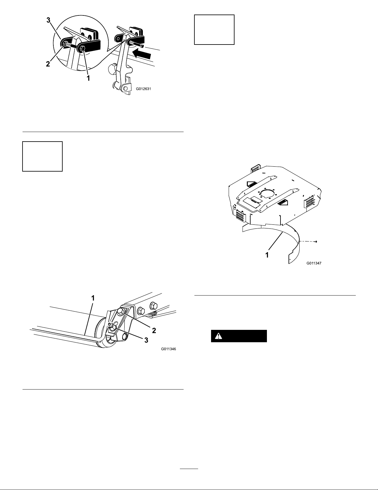
AdjustingtheRoller Scraper(Optional)
NoPartsRequired
Figure6
3.Armofhood-lockbracket
3
InstallingtheMulching
Bafe(Optional)
NoPartsRequired
g012631
Procedure
1.Thoroughlycleandebrisfromthemounting
holesontherearwallandleftsidewallofthe
chamber.
2.Installthemulchingbafeintherearopening
andsecureitwith5ange-headbolts(Figure8).
Procedure
Theoptionalrearrollerscraperisdesignedtowork
bestwhenthereisanevengapof0.5to1mm(0.020
to0.040inch)betweenthescraperandroller.
1.Loosenthegreasettingandthemounting
screw(Figure7).
1.Mulchingbafe
3.Verifythatmulchingbafedoesnotinterferewith
thetipofthebladeanddoesnotprotrudeinside
thesurfaceoftherearchamberwall.
Figure8
DANGER
g011346
Figure7
1.Rollerscraper
2.Mountingscrew
2.Slidethescraperupordownuntilagapof0.5to
1mm(0.020to0.040inch)isachievedbetween
therodandtheroller.
3.Securethegreasettingandscrewto41N-m
(30ft-lb)inanalternatingsequence.
3.Greasetting
Usingthehigh-liftbladewiththe
mulchingbafecouldcausetheblade
tobreak,resultinginpersonalinjuryor
death.
Donotusethehigh-liftbladewiththe
mulchingbafe.
g011347
12

ProductOverview
4
PreparingtheMachine
NoPartsRequired
CheckingtheTirePressure
Checkthetirepressurebeforeuse;refertoChecking
theTirePressure(page23).
Important:Maintainpressureinalltiresto
ensureagoodquality-of-cutandpropermachine
performance.Donotunderinatethetires.
CheckingtheFluidLevels
1.Checktherear-axlelubricantlevelbeforethe
engineisrststarted,refertoCheckingtheRear
AxleGearBoxLubricant(page55).
2.Checktheengine-oillevelbeforestartingthe
engine;refertoCheckingtheEngine-OilLevel
(page47).
Controls
BrakePedals
2footpedals(Figure9)operateindividualwheel
brakesforturningassistanceandtoaidinobtaining
bettersidehilltraction.
Pedal-LockingLatch
Thepedal-lockinglatch(Figure9)connectsthebrake
pedals.Usethelatchtoconnectthepedalstoengage
theparkingbrakeandwhileoperatingthemachine
intransportmode.
Parking-BrakePedal
Toengagetheparkingbrake,(Figure9)connectthe
pedalstogetherwiththepedal-lockinglatchandpush
downontherightbrakepedalwhileengagingthetoe
pedal.Toreleasetheparkingbrake,press1ofthe
brakepedalsuntiltheparkingbrakelatchretracts.
3.Checkthehydraulic-uidlevelbeforestarting
theengine;refertoCheckingtheHydraulic-Fluid
Level(page59).
4.Checkthecoolingsystembeforestartingthe
engine;refertoCheckingtheCoolingSystem
(page56).
GreasingtheMachine
Greasethemachinebeforeuse;refertoGreasingthe
BearingsandBushings(page44).Failuretoproperly
greasethemachineresultsinprematurefailureof
criticalparts.
g009979
Figure9
1.Brakepedal4.Tractionpedal
2.Pedal-lockinglatch5.Tilt-steeringpedal
3.Parking-brakepedal
TractionPedal
Thetractionpedal(Figure9)controlsforwardand
reverseoperation.Pressthetopofthepedaltomove
forwardandthebottomtomovebackward.
Tostopthemachine,useoneofthefollowing
procedures:
•Reduceyourfootpressureonthetractionpedal
andallowittoreturntothecenterposition.The
machinewilldynamicallybraketoasmoothstop.
•Taporholdthereversepedalbriey.Thisstops
themachinefasterthandynamicbraking.
13

Note:Inemergencybrakingsituations,pressthe
g020512
servicebrakepedalsinadditiontousingthereverse
pedalasstatedabove.Thisisthequickestmethod
tostopthemachine.
engagethecuttingunitblades.Pushinthebuttonto
disengagethecuttingunitblades.
Engine-SpeedSwitch
Tilt-SteeringPedal
Totiltthesteeringwheeltowardyou,pressthefoot
pedal(Figure9)down,andpullthesteeringtower
towardyoutothemostcomfortablepositionandthen
releasethepedal.
High-LowSpeedControl
Theswitch(Figure10)allowsthespeedrangeto
increasefortransportingthemachine.Toswitch
betweentheHighandLowspeedranges,raisethe
decks,disengagethePTO,putthetractionpedal
intotheNEUTRALposition,andmovethemachineat
aslowspeed.
Note:Thecuttingdecksdonotoperateand/or
cannotbeloweredfromthetransportpositionwhen
theswitchisinthehighrange.
Theengine-speedswitch(Figure10)has2modesto
changetheenginespeed.T aptheswitchtoincrease
ordecreasetheenginespeedin100rpmincrements.
HolddowntheswitchtoautomaticallymovetoHigh
orLowidle,dependingonwhichendoftheswitchis
depressed.
LiftSwitches
Theliftswitches(Figure10)raiseandlowerthe
cuttingunits.Presstheswitchesforwardtolowerthe
cuttingunitsandbackwardtoraisethecuttingunits.
Whenstartingthemachine,withthecuttingunitsin
thedownposition,presstheliftswitchdowntoallow
thecuttingunitstooat,andmow.
Note:ThedecksdonotlowerwhileintheHispeed
rangeandtheydonotraiseorloweriftheoperatoris
outoftheseatwhentheengineisrunning.Tolower
thedecksforservice,rotatethekeyintheignition
switchtotheONpositionwhilesittingintheseat.
LightSwitch
Presstheloweredgeoftheswitch(Figure10)toturn
onthelights.Presstheupperedgeoftheswitchto
turnoffthelights.
Figure10
1.Liftswitches
(Groundsmaster4700
only)
2.Liftswitch(Groundsmaster
4500and4700)
3.PTOswitch
4.Keyswitch
5.InfoCenter
6.Hi-Lospeedcontrol
7.Engine-speedswitch
8.Lightswitch
9.Cruisecontrol
KeySwitch
Thekeyswitch(Figure10)has3positions:Off,
On/Preheat,andStart.
PTOSwitch
ThePTOswitch(Figure10)has2positions:Out
(start)andIn(stop).PullthePTObuttonoutto
PowerPoint
Usethepowerpoint(Figure11)topoweroptional12
Velectricalaccessories.
g020433
g020512
Figure11
1.Powerpoint2.Bagholder
14

BagHolder
1
g020650
2
3
4
TORO
UsingtheInfoCenterLCDDisplay
Usethebagholder(Figure1 1)forstorage.
SeatAdjustments
SeatAdjustingLever
Pulloutonthelevertoslidetheseatforwardor
rearward(Figure12).
SeatArmRestAdjustingKnob
Rotatetheknobtoadjusttheseatarmrestangle.
SeatBackAdjustingLever
Movethelevertoadjusttheseatbackangle(Figure
12).
Weightgauge
Indicateswhentheseatisadjustedtotheweightof
theoperator(Figure12).Heightadjustmentismade
bypositioningthesuspensionwithintherangeofthe
greenregion.
TheInfoCenterLCDdisplayshowsinformationabout
yourmachine,suchastheoperatingstatus,various
diagnosticsandotherinformationaboutthemachine
(Figure13).Thereisasplashscreenandmain
informationscreenoftheInfoCenter.Youcanswitch
betweenthesplashscreenandmaininformation
screenatanytimebypressinganyoftheInfoCenter
buttonsandthenselectingtheappropriatedirectional
arrow.
g020650
Figure13
1.Indicatorlight3.Middlebutton
2.Rightbutton
4.Leftbutton
•LeftButton,MenuAccess/BackButton—pressthis
buttontoaccesstheInfoCentermenus.Youcan
useittoexitanymenuthatyouarecurrentlyusing.
•MiddleButton—usethisbuttontoscrolldown
menus.
•RightButton—usethisbuttontoopenamenu
wherearightarrowindicatesadditionalcontent.
•Beeper—activatedwhenloweringthedecksorfor
advisoriesandfaults.
Note:Thepurposeofeachbuttonmaychange
g008837
Figure12
1.Weightgauge
2.Weight-adjustinglever5.Armrestadjustingknob
3.Seatadjustinglever
4.Seatbackadjustinglever
(notshown-locatedunder
armrest)
dependingonwhatisrequiredatthetime.Each
buttonislabeledwithanicondisplayingitscurrent
function.
Weight-AdjustingLever
Adjustforyourweight(Figure12).Pulluptheleverto
increasetheairpressureandpushdowntodecrease
theairpressure.Youattaintheproperadjustment
whentheweightgaugeisinthegreenregion.
15

InfoCenterIconDescription
SERVICEDUE
Indicateswhenscheduledservice
shouldbeperformed
Thestatusoftheenginerpm.
InfoCenterIconDescription(cont'd.)
Thecruisecontrolison.
Infoicon
Maximumtractionspeedsetting
Fast
Slow
Thefanisreversed.
Stationaryregenerationisrequired.
Theair-intakeheaterisactive
Raisetheleftdeck.
Raisethecenterdeck
Raisetherightdeck
Theoperatormustsitintheseat.
Theparkingbrakeison.
Therangeishigh.
Neutral
IdentiestherangeasLow
Coolanttemperature(°Cor°F)
Temperature(hot)
TractionorTractionPedal
Notallowed
Starttheengine.
Stoptheengine.
Engine
Keyswitch
Cuttingunitsarelowering.
Cuttingunitsareraising.
PINcode
Hydraulicuidtemperature
CANbus
InfoCenter
Badorfailed
Center
Right
Left
Bulb
OutputofTECcontrollerorcontrol
wireinharness
Overtheallowedrange
Undertheallowedrange
Outofrange
/
Switch
Operatormustreleaseswitch.
Operatorshouldchangetoindicated
state.
ThePTOison.
16

InfoCenterIconDescription(cont'd.)
Symbolsareoften
combinedtoform
sentences.Some
examplesareshown
below
Operatorshouldputmachinein
neutral.
Enginestartisdenied.
Service
MenuItemDescription
Hours
CountsListsthenumberofstarts,
Liststhetotalnumberofhours
thatthemachine,engineand
fanhavebeenon,aswell
asthenumberofhoursthe
machinehasbeentransported
andoverheated.
deckPTOcycles,andfan
reversalsthemachinehas
experienced.
Engineshutdown.
Enginecoolantistoohot.
Hydraulicuidistoohot.
DPFashaccumulationnotication.
RefertoServicingtheDiesel
ParticulateFilter(DPF)inthe
maintenancesectionfordetails.
Sitdownorsetparkingbrake.
UsingtheMenus
ToaccesstheInfoCentermenusystem,pressthe
menuaccessbuttonwhileatthemainscreen.This
bringsyoutothemainmenu.Refertothefollowing
tablesforasynopsisoftheoptionsavailablefrom
themenus:
MainMenu
MenuItemDescription
Faults
ServiceContainsinformationonthe
DiagnosticsListsvariousstatesthatthe
Settings
AboutListsthemodelnumber,serial
Containsalistoftherecent
machinefaults.Referto
theServiceManualoryour
ToroDistributorformore
informationontheFaults
menuandtheinformation
containedthere.
machinesuchashoursofuse
andothersimilarnumbers.
machinecurrentlyhas.You
canusethistotroubleshoot
certainissuesasitquicklytells
youwhichmachinecontrols
areonandwhichareoff.
Allowsyoutocustomizeand
modifycongurationvariables
ontheInfoCenterdisplay.
number,andsoftwareversion
ofyourmachine.
Diagnostics
MenuItemDescription
LeftDeck
CenterDeck
RightDeck
TractionPedal
Traction
HI/LORange
PTO
EngineRun
Settings
MenuItemDescription
Units
Language
LCDBacklightControlsthebrightnessofthe
LCDContrastControlsthecontrastofthe
ProtectedMenusAllowsapersonauthorized
ProtectSettings
AutoIdle
MowSpeedControlsthemaximumspeed
Trans.SpeedControlsthemaximumspeed
CounterbalanceControlstheamountof
RefertotheServiceManualor
yourToroDistributorformore
informationontheEngine
Runmenuandtheinformation
containedthere.
Controlstheunitsusedonthe
InfoCenter(EnglishorMetric).
Controlsthelanguageused
ontheInfoCenter*.
LCDdisplay.
LCDdisplay.
byyourcompanywiththe
PINcodetoaccessprotected
menus.
Allowstheabilitytochange
thesettingsintheprotected
settings.
Controlstheamountoftime
allowedbeforeidlingthe
enginewhenthemachineis
notinuse.
whileinmow(lowrange).
whileintransport(highrange).
counterbalanceappliedbythe
decks.
*Only"operator-faced"textistranslated.Faults,
Service,andDiagnosticsscreensare"service-faced.”
Titlesareintheselectedlanguage,butmenuitems
areinEnglish.
17

About
MenuItemDescription
Model
SNListstheserialnumberofthe
S/WRevListsthesoftwarerevisionof
Liststhemodelnumberofthe
machine.
machine.
themastercontroller .
ProtectedMenus
Thereare5operatingcongurationsettingsthatare
adjustablewithintheSettingsMenuoftheInfoCenter:
autoidle,maximummowinggroundspeed,maximum
transportgroundspeed,SmartPower,anddeck
counterbalance.ThesesettingsareintheProtected
Menu.
AccessingProtectedMenus
Note:ThefactorydefaultPINcodeforyoumachine
iseither0000or1234.
IfyouchangedthePINcodeandforgotthe
code,contactyourAuthorizedToroDistributorfor
assistance.
1.FromtheMAINMENU,usethecenterbuttonto
scrolldowntotheSETTINGSMENUandpressthe
rightbutton(Figure14).
Figure14
2.IntheSETTINGSMENU,usethecenterbuttonto
scrolldowntothePROTECTEDMENUandpress
therightbutton(Figure15A).
g028522
Figure15
3.T oenterthePINcode,pressthecenterbutton
untilthecorrectrstdigitappears,thenpress
therightbuttontomoveontothenextdigit
(Figure15BandFigure15C).Repeatthisstep
untilthelastdigitisenteredandpresstheright
buttononcemore.
4.PressthemiddlebuttontoenterthePINcode
(Figure15D).
WaituntiltheredindicatorlightoftheInfoCenter
illuminates.
Note:IftheInfoCenteracceptsthePINcode
andtheprotectedmenuisunlocked,theword
“PIN”displaysintheupperrightcornerofthe
screen.
g028523
Note:RotatethekeyswitchtotheOFFpositionand
thentotheONpositionlockstheprotectedmenu.
Youhavetheabilitytoviewandchangethesettingsin
theProtectedMenu.OnceyouaccesstheProtected
Menu,scrolldowntoProtectSettingsoption.Usethe
rightbuttontochangethesetting.SettingtheProtect
SettingstoOFFallowsyoutoviewandchangethe
settingsintheProtectedMenuwithoutenteringthe
PINcode.SettingtheProtectSettingstoONhidesthe
protectedoptionsandrequiresyoutoenterthePIN
codetochangethesettingintheProtectedMenu.
AfteryousetthePINcode,rotatethekeyswitchOFF
andbacktotheONpositiontoenableandsavethis
feature.
18

ViewingandChangingthe
SettingtheCounterbalance
ProtectedMenuSettings
1.IntheProtectedMenu,scrolldowntoProtect
Settings.
2.T oviewandchangethesettingswithoutentering
apasscode,usetherightbuttontochangethe
ProtectSettingstoOFF.
3.T oviewandchangethesettingswitha
passcode,usetheleftbuttontoselectON,set
thepasscode,andturnthekeyintheignition
switchtotheOFFpositionandthentotheON
position.
SettingtheAutoIdle
1.IntheSettingsMenu,scrolldowntoAutoIdle.
2.Presstherightbuttontochangetheauto-idle
timebetweenOFF,8S,10S,15S,20S,and30S.
SettingtheMaximumAllowed
MowSpeed
1.IntheSettingsMenu,scrolldowntoMowSpeed
andpresstherightbutton.
1.IntheSettingsMenu,scrolldowntoCounter
Balanceandpresstherightbutton.
2.PresstherightbuttontoswitchbetweenLow,
Med,andHigh.
WhennishedwiththeProtectedMenu,presstheleft
buttontoexittotheMainMenu,thenpresstheleft
buttontoexittotheRunMenu.
2.Usetherightbuttontoincreasethemaxfull
mowspeed(50%,75%,or100%).
3.Usethecenterbuttontodecreasethemaxfull
mowspeed(50%,75%,or100%).
4.Presstheleftbuttontoexit.
SettingtheMaximumAllowed
TransportSpeed
1.IntheSettingsMenu,scrolldowntoTransport
Speedandpresstherightbutton.
2.Usetherightbuttontoincreasethemax
transportspeed(50%,75%,or100%).
3.Usethecenterbuttontodecreasethemax
transportspeed(50%,75%,or100%).
4.Presstheleftbuttontoexit.
TurningtheSmartPowerON/OFF
1.Inthesettingsmenu,scrolldowntoSmart
Power.
2.PresstherightbuttontoswitchbetweenONand
OFF.
3.Presstheleftbuttontoexit.
19

Specications
Note:Specicationsanddesignaresubjectto
changewithoutnotice.
4500-D4700-D
Widthofcut2.8m(109inches)3.8m(150inches)
Overallwidth,
cuttingunitsdown
Overallwidth,
cuttingunitsup
(transport)
Overalllength370cm(145.8inches)370cm(145.8inches)
HeightwithROPS216cm(85inches)216cm(85inches)
Groundclearance15cm(6inches)15cm(6inches)
TrackWidth,front224cm(88.3inches)224cm(88.3inches)
TrackWidth,rear
Wheelbase
NetWeight(with
cuttingunitsand
nouids)
CuttingDeck
Length
Width
Height
Weight
286cm(1 12.8inches)391cm(153.8inches)
224cm(88.25inches)224cm(88.25inches)
141cm(55.5inches)141cm(55.5inches)
171cm(67-1/2inches)171cm(67-1/2inches)
1894kg(4175lb)2,234kg(4,925lb)
24.4cm(9.6inches)tocarriermount
26.7cm(10–1/2inches)at3/4inchheightofcut
34.9cm(13–3/4inches)at4inchheightofcut
86.4cm(34inches)
86.4cm(34inches)
88kg(195lb)
Attachments/Accessories
AselectionofToroapprovedattachmentsandaccessoriesisavailableforusewiththemachinetoenhance
andexpanditscapabilities.ContactyourAuthorizedServiceDealerorDistributororgotowww.Toro.comfora
listofallapprovedattachmentsandaccessories.
TobestprotectyourinvestmentandmaintainoptimalperformanceofyourToroequipment,countonT oro
genuineparts.Whenitcomestoreliability,Torodeliversreplacementpartsdesignedtotheexactengineering
specicationofourequipment.Forpeaceofmind,insistonTorogenuineparts.
20

Operation
FuelSafety
Note:Determinetheleftandrightsidesofthe
machinefromthenormaloperatingposition.
BeforeOperation
BeforeOperationSafety
GeneralSafety
•Neverallowchildrenoruntrainedpeopleto
operateorservicethemachine.Localregulations
mayrestricttheageoftheoperator.Theowner
isresponsiblefortrainingalloperatorsand
mechanics.
•Becomefamiliarwiththesafeoperationofthe
equipment,operatorcontrols,andsafetysigns.
Knowhowtostopthemachineandenginequickly.
•Checkthatallsafetydevicesareattachedand
functioningproperly.Thisincludes,butisnot
limitedto,operator-presencecontrols;safety
switchesandshields;therolloverprotection
system(ROPS);attachments;andbrakes.Do
notoperatethemachineunlessallsafetydevices
areinpositionandfunctioningasintendedbythe
manufacturer.
•Alwaysinspectthemachinetoensurethatthe
blades,bladebolts,andcuttingassemblyarenot
wornordamaged.Replacewornordamaged
bladesandboltsinsetstopreservebalance.
•Inspecttheareawhereyouwillusethemachine
andremoveallobjectsthatthemachinecould
potentiallythrow.
•Evaluatetheterraintodeterminetheappropriate
equipmentandanyattachmentsoraccessories
requiredtooperatethemachineproperlyand
safely.
DANGER
Incertainconditions,fuelisextremely
ammableandhighlyexplosive.Areor
explosionfromfuelcanburnyouandothers
andcandamageproperty.
•Fillthefueltankoutdoors,inanopenarea,
whentheengineiscold.Wipeupanyfuel
thatspills.
•Neverllthefueltankinsideanenclosed
trailer.
•Neversmokewhenhandlingfuel,andstay
awayfromanopenameorwherefuel
fumesmaybeignitedbyaspark.
•Storefuelinanapprovedcontainerand
keepitoutofthereachofchildren.Never
buymorethana180-daysupplyoffuel.
•Donotoperatethemachinewithoutthe
entireexhaustsysteminplaceandin
properworkingcondition.
WARNING
Fuelisharmfulorfatalifswallowed.
Long-termexposuretovaporscancause
seriousinjuryandillness.
•Avoidprolongedbreathingofvapors.
•Keepyourhandsandfaceawayfromthe
nozzleandthefuel-tankopening.
•Keepfuelawayfromyoureyesandskin.
•Useonlyanapprovedfuelcontainer.
•Neverremovethefuelcaporaddfueltothefuel
tankwhiletheengineisrunning.
•Neverllcontainersinsideavehicleoronatruck
ortrailerbedwithaplasticliner.Alwaysplace
containersonthegroundandawayfromyour
vehiclebeforelling.
•Removetheequipmentfromthetruckortrailer
andaddfueltoitwhileitisontheground.Ifthis
isnotpossible,thenaddfuelusingaportable
containerratherthanfromafuel-dispensernozzle.
•Keepthefuel-dispensernozzleincontactwith
therimofthefueltankorcontaineropeningat
alltimesuntilfuelingiscomplete.Donotusea
nozzlelock-opendevice.
•Ifyouspillfuelonyourclothing,changeyour
clothingimmediately.
•Fillthefueltankuntilthefuellevelis25mm(1
inch)belowthebottomofthellerneck.Donot
21

overllthefueltank.Replacethefuel-tankcap
andtightenitsecurely.
CheckingtheEngine-Oil Level
Beforeyoustarttheengineandusethemachine,
checktheoillevelintheenginecrankcase;referto
CheckingtheEngine-OilLevel(page47).
CheckingtheCooling System
Beforeyoustarttheengineandusethemachine,
checkthecoolingsystem;refertoCheckingthe
CoolingSystem(page56).
CheckingtheHydraulic System
Beforeyoustarttheengineandusethemachine,
checkthehydraulicsystem;refertoCheckingthe
HydraulicLinesandHoses(page61).
FuelTable
Dieselfuelspecication
ASTMD975
No.1-DS15
No.2-DS15
EN590EuropeanUnion
ISO8217DMX
JISK2204GradeNo.2
KSM-2610
Location
USA
International
Japan
Korea
•Useonlyclean,freshdieselfuelorbiodieselfuels.
•Purchasefuelinquantitiesthatcanbeusedwithin
180daystoensurefuelfreshness.
Usesummer-gradedieselfuel(No.2-D)at
temperaturesabove-7°C(20°F)andwinter-grade
fuel(No.1-DorNo.1-D/2-Dblend)belowthat
temperature.
Note:Useofwinter-gradefuelatlowertemperatures
provideslowerashpointandcoldowcharacteristics
whicheasesstartingandreducesfuellterplugging.
Usingsummer-gradefuelabove-7°C(20°F)
contributestowardlongerfuelpumplifeandincreased
powercomparedtowinter-gradefuel.
FillingtheFuelTank
FuelTankCapacity
Fueltankcapacity:83L(22USgallons)
FuelSpecication
Important:Useonlyultra-lowsulphurdiesel
fuel.Fuelwithhigherratesofsulfurdegrades
thedieseloxidationcatalyst(DOC),whichcauses
operationalproblemsandshortenstheservicelife
ofenginecomponents.
Failuretoobservethefollowingcautionsmay
damagetheengine.
•Neverusekeroseneorgasolineinsteadofdiesel
fuel.
•Nevermixkeroseneorusedengineoilwiththe
dieselfuel.
•Neverkeepfuelincontainerswithzincplatingon
theinside.
•Donotusefueladditives.
PetroleumDiesel
Biodiesel
Thismachinecanalsouseabiodieselblendedfuelof
uptoB20(20%biodiesel,80%petroleumdiesel).
Sulfurcontent:Ultra-lowsulfur(<15ppm)
Biodieselfuelspecication:ASTMD6751or
EN14214
Blendedfuelspecication:ASTMD975,EN590,
orJISK2204
Important:Thepetroleumdieselportionmust
beultra-lowsulfur.
Observethefollowingprecautions:
•Biodieselblendsmaydamagepaintedsurfaces.
•UseB5(biodieselcontentof5%)orlesserblends
incoldweather.
•Monitorseals,hoses,gasketsincontactwithfuel
astheymaybedegradedovertime.
•Fuellterpluggingmaybeexpectedforatime
afterconvertingtobiodieselblends.
•ContactyourAuthorizedT oroDistributorifyou
wishformoreinformationonbiodiesel.
Cetanerating:45orhigher
Sulfurcontent:Ultra-lowsulfur(<15ppm)
22

AddingFuel
CheckingtheTirePressure
ServiceInterval:Beforeeachuseordaily
Thecorrectairpressureinthetiresis138kPa(20psi).
Important:Maintaintherecommendedpressure
inalltirestoensureagoodqualityofcutand
propermachineperformance.Donotunder-inate
g031874
thetires.
Checktheairpressureinallthetiresbefore
operatingthemachine.
g001055
Figure17
Figure16
Fillthetankwithdieselfueluntilthelevelreachesthe
bottomofthellerneck.
Note:Ifpossible,llthefueltankaftereachuse;this
willminimizepossiblebuildupofcondensationinside
thefueltank.
CheckingtheTorqueofthe WheelNuts
ServiceInterval:Aftertherst8hours
Every200hours
g031869
WARNING
Failuretomaintainpropertorqueofthewheel
nutscouldresultinfailureorlossofwheel
andmayresultinpersonalinjury.
Torquethefrontandrearwheelnutsto115to
136N-m(85to100ft-lb)after1to4hoursof
operationandagainafter8hoursofoperation.
Torqueevery200hoursthereafter.
Note:Frontwheelnutsare1/2-20UNF.Rearwheel
nutsareM12x1.6-6H(Metric).
23

AdjustingtheHeightofCut
Important:Thiscuttingdeckoftencuts
approximately6mm(1/4inch)lowerthanareel
cuttingunitwiththesamebenchsetting.Itmay
benecessarytohavetheserotarycuttingdeck’s
benchset6mm(1/4inch)abovethatofreels
cuttinginthesamearea.
Important:Accesstotherearcuttingunitsis
greatlyimprovedbyremovingthecuttingunit
fromthetractor.
1.Lowerthecuttingdecktotheground,shutoff
theengine,andremovethekeyfromtheignition
switch.
2.Loosentheboltsecuringeachheight-of-cut
brackettotheheight-of-cutplate(frontandeach
side);refertoFigure18.
7.Installtheboltnger-tight.
8.Repeatsteps4through7foreachside
adjustment.
9.T orqueall3boltsto41N∙m(30ft-lb).Always
tightenthefrontboltrst.
Note:Adjustmentsofmorethan3.8cm(1-1/2
inches)mayrequiretemporaryassemblytoan
intermediateheighttopreventbinding(e.g.,
changingfrom3.1to7cm(1.25to2.75inches)
heightofcut).
CheckingtheInterlock Switches
ServiceInterval:Beforeeachuseordaily
3.Beginningwithfrontadjustment,removethe
bolt.
Figure18
1.Height-of-cutbracket3.Spacer
2.Height-of-cutplate
4.Whilesupportingthechamber,removethe
spacer(Figure18).
5.Movethechambertothedesiredheightof
cutandinstallaspacerintothedesignated
height-of-cutholeandslot(Figure19).
CAUTION
Ifsafetyinterlockswitchesaredisconnected
ordamaged,themachinecouldoperate
unexpectedlycausingpersonalinjury.
•Donottamperwiththeinterlockswitches.
•Checktheoperationoftheinterlock
switchesdailyandreplaceanydamaged
switchesbeforeoperatingthemachine.
Theinterlockswitchesaredesignedtostopthe
machinewhentheoperatorgetsofftheseatwhenthe
tractionpedalisdepressed.However,theoperator
maygetofftheseatwhiletheengineisrunningand
thetractionpedalisintheNEUTRALposition.Although
g011344
theenginecontinuestorunifthePTOswitchis
disengagedandthetractionpedalisreleased,itis
stronglyrecommendedthattheenginebestopped
beforerisingfromtheseat.
1.Parkthemachineonalevelsurface,lowerthe
cuttingunit,turnthekeyintheignitionswitchto
theOFFposition,andengagetheparkingbrake.
2.Pressthetractionpedal.Turnthekeyinthe
ignitionswitchtotheONposition.
Note:Iftheenginecranks,thereisa
malfunctionintheinterlocksystem.Correctthis
malfunctionbeforeoperatingthemachine.
3.TurnthekeyintheignitionswitchtotheON
position,risefromtheseat,andmovethePTO
switchtoON.
g026184
Figure19
6.Positionthetappedplatein-linewiththespacer.
Note:ThePTOshouldnotengage.Ifthe
PTOengages,thereisamalfunctioninthe
interlocksystem.Correctthismalfunctionbefore
operatingthemachine.
4.Engagetheparkingbrake,turnthekeyinthe
ignitionswitchtotheONposition,andmovethe
tractionpedaloutofNEUTRAL.
24

Note:TheInfoCenterdisplays"tractiondenied"
andthemachineshouldnotmove.Ifthe
machinedoesmove,thereisamalfunctionin
theinterlocksystem.Correctthismalfunction
beforeoperatingthemachine.
Checkingthe Blade-StoppingTime
ServiceInterval:Beforeeachuseordaily
Thebladesofthecuttingdeckshouldcometoa
completestopinapproximately5secondsafteryou
shutdownthecuttingdeckengagementswitch.
Note:Makesurethatthedecksareloweredontoa
cleansectionofturforhardsurfacetoavoidthrown
dustanddebris.
Toverifythisstoppingtime,haveasecondperson
standbackfromthedeckatleast6m(20ft)and
watchthebladeson1ofthecuttingdecks.Havethe
operatorshutthecuttingdecksdownandrecordthe
timeittakesforthebladestocometoacomplete
stop.Ifthistimeisgreaterthan7seconds,thebraking
valveneedsadjustment.CallyourT oroDistributorfor
assistanceinmakingthisadjustment.
Attributes:
•Moreliftandhigherdischargevelocity.
•Sparseorlimpturfispickedupsignicantlyat
higherheightsofcut.
•Wetorstickyclippingsaredischargedmore
efcientlyreducingcongestioninthedeck.
•Requiresmorehorsepowertorun.
•Tendstodischargefurtherleftandcantendto
windrowatlowerheightsofcut.
DANGER
Usingthehigh-liftbladewiththemulching
bafecouldcausethebladetobreak,
resultinginpersonalinjuryordeath.
Donotusethehigh-liftbladewiththebafe.
AtomicBlade
Thisbladewasdesignedtoprovideexcellentleaf
mulching.
Attributes:Excellentleafmulching
SelectingaBlade
StandardCombinationSail
Thisbladewasdesignedtoprovideexcellentliftand
dispersioninalmostanycondition.Ifmoreorlesslift
anddischargevelocityisrequired,consideradifferent
blade.
Attributes:Excellentliftanddispersioninmost
conditions.
AngledSail
Thebladegenerallyperformsbestinlowerheightsof
cut—1.9to6.4cm(3/4to2-1/2inches).
Attributes:
•Dischargeremainsmoreevenatlowerheightsof
cut.
•Dischargehaslesstendencytothrowleftandthus
acleanerlookaroundbunkersandfairways.
•Lowerpowerrequirementatlowerheightsand
denseturf.
High-Lift,ParallelSail
Thebladegenerallyperformsbetterinthehigher
heightsofcut—7to10cm(2to4inches).
25

ChoosingAccessories
OptionalEquipmentCongurations
AngleSailBladeHigh-Lift,Parallel-Sail
GrassCutting:1.9to4.4
cm(0.75to1.75inch)
heightofcut
GrassCutting:5to6.4
cm(2.00to2.50inch)
heightofcut
GrassCutting:7to10
cm(2.75to4.00inch)
heightofcut
LeafMulchingRecommendedforuse
ProsEvendischargeatlower
ConsDoesnotliftthegrass
Recommendedinmost
applications
Recommendedforthick
orlushturf
Mayworkwellinlushturf
withthemulchingbafe
heightofcutCleaner
lookaroundbunkersand
fairwaysLowerpower
requirements
wellinhighheightof
cutapplicationsWet
orstickygrasshasa
tendencytobuildupin
thechamber,leading
topoorqualityofcut
andhigherpower
requirements
Blade(Donotusewith
themulchingbafe)
Mayworkwellinlightor
sparseturf
Recommendedforlight
orsparseturf
Recommendedinmost
applications
NotAllowedUsewithcombination
Moreliftandhigher
dischargevelocity
Sparseorlimpturfis
pickedupathighheight
ofcutWetorsticky
clippingsaredischarged
efciently
Requiresmorepowerto
runinsomeapplications
Tendstowindrowat
lowerheightofcutin
lushgrassDonotuse
withthemulchingbafe
MulchingBafeRollerScraper
Hasbeenshownto
improvedispersionand
aftercutperformance
onnortherngrassesthat
arecutatleast3times
perweekandlessthan
1/3ofthegrassblade
isremoved.Donot
usewiththehigh-lift,
parallel-sailblade
sailoranglesailblade
only
Mayimprovedispersion
andappearancein
certaingrasscutting
applicationsVerygood
forleafmulching
Grasswillbuildupinthe
chamberifattemptingto
removetoomuchgrass
withbafeinplace
Canbeusedanytime
thatrollersbuildupwith
grassorlargeatgrass
clumpsofgrassare
seen.Thescrapers
mayactuallyincrease
clumpingincertain
applications.
Reducesrollerbuildup
incertainapplications
26

DuringOperation
DuringOperationSafety
GeneralSafety
•Theowner/usercanpreventandisresponsible
foraccidentsthatmaycauseinjuriestopeople,
ordamagetoproperty.
•Wearappropriateclothing,includingeye
protection;substantial,slip-resistantfootwear;and
hearingprotection.Tiebacklonghair.Donot
wearjewelry.
•EnsurethatalldrivesareintheNEUTRALposition,
theparkingbrakeisengaged,andyouareinthe
operatingpositionbeforeyoustarttheengine.
•Keepallbodyparts,includinghandsandfeet,
awayfromallmovingparts.
•Donotoperatethemachinewhileill,tired,or
undertheinuenceofalcoholordrugs.
•Keepthedirectionofthemowerdischargeaway
frompeopleandpets.
•Donotmowinreverseunlessitisabsolutely
necessary.Ifyoumustmowinreverse,look
behindanddownforsmallchildrenbeforeand
whilemovingthemachineinreverse.Stayalert
andstopthemachineifachildentersthearea.
•Useextremecarewhenapproachingblind
corners,shrubs,trees,orotherobjectsthatmay
blockyourview.
•Donotmowneardrop-offs,ditches,or
embankments.Themachinecouldsuddenly
rolloverifawheelgoesovertheedgeorifthe
edgecavesin.
•Nevercarrypassengersonthemachine.
•Operatethemachineonlyingoodvisibilityand
appropriateweatherconditions.Donotoperate
themachinewhenthereistheriskoflighting.
•Donotmowonwetgrass.Reducedtractioncould
causethemachinetoslide.
•Neverraisethemowerdeckwiththeblades
running.
•Stopthemachineandinspectthebladesafter
strikinganobjectorifthereisanabnormal
vibrationinthemachine.Makeallnecessary
repairsbeforeresumingoperation.
•Stopthebladeswheneveryouarenotmowing,
especiallywhilecrossinglooseterrainsuchas
gravel.
•Slowdownandusecautionwhenmakingturns
andcrossingroadsandsidewalkswiththe
machine.Alwaysyieldtheright-of-way.
•Turnontheashingwarninglightsonthemachine
wheneveryoutravelonapublicroad,except
wheresuchuseisprohibitedbylaw.
•Disengagethedrivetotheattachmentandshutoff
theenginebeforeaddingfuelandadjustingthe
heightofcut.
•Reducethethrottlesettingbeforestoppingthe
engineand,iftheenginehasafuel-shutoffvalve,
shutoffthefuelwhenyouhavenishedoperating
themachine.
•Neverrunanengineinanareawhereexhaust
gasesareenclosed.
•Neverleavearunningengineunattended.
•Beforeleavingtheoperatingposition,dothe
following:
–Stopthemachineonlevelground.
–Disengagethepowertake-offandlowerthe
attachments.
–Settheparkingbrake.
–Shutofftheengineandremovethekey .
–Waitforallmovingpartstostop.
•Donotchangethegovernorsettingsonor
overspeedtheengine.Operatingtheengineat
excessivespeedmayincreasethepotentialfor
personalinjury.
•Donotusethemachineasatowingvehicle.
•Useaccessoriesandattachmentsapprovedby
TheT oro®Companyonly.
RolloverProtectionSystem
(ROPS)Safety
•DonotremovetheROPSfromthemachine.
•Ensurethattheseatbeltisattachedandthatyou
canreleaseitquicklyintheeventofanemergency.
•Alwayswearyourseatbelt.
•Checkcarefullyforoverheadclearances,suchas
branches,doorways,andelectricalwires,before
drivingthemachineunderthem.Donotcontact
them.
•KeeptheROPSinsafeoperatingconditionby
thoroughlyinspectingitperiodicallyfordamage
andkeepingallthemountingfastenerstight.
•ReplaceadamagedROPS.Donotrepairorrevise
it.
•AnyalterationstoaROPSmustbeapprovedby
TheT oro®Company.
SlopeSafety
•Slowdownthemachineanduseextracareon
hillsides.Travelintherecommendeddirectionon
hillsides.Turfconditionscanaffectthestabilityof
themachine.
27

•Avoidstarting,stopping,orturningthemachine
onaslope.Ifthetireslosetraction,disengage
theblade(s)andproceedslowlystraightdownthe
slope.
•Donotturnthemachinesharply.Usecarewhen
reversingthemachine.
•Whenoperatingthemachineonaslope,always
keepallcuttingunitslowered.
•Avoidturningthemachineonslopes.Ifyoumust
turn,turnslowlyandgraduallydownhill,ifpossible.
•Useextracarewhileoperatingthemachinewith
attachments;theycanaffectthestabilityofthe
machine.Followtherecommendationsforusing
themachineonaslopeinthisOperator’sManual.
StartingandStoppingthe Engine
Important:Bleedthefuelsystembeforestarting
theengineiftheenginehasstoppedduetolack
offuel,oryouhaveperformedmaintenanceon
thefuelsystem.
StartingtheEngine
1.Sitontheseat,keepyourfootoffthetraction
pedalsothatitisinNEUTRAL,andengagethe
parkingbrake.
2.TurnthekeyintheignitionswitchtotheRUN
position.Theglowindicatorwilllight.
3.Whentheglowindicatordims,turnthekeyinthe
ignitionswitchtotheSTARTposition.Release
thekeyimmediatelywhentheenginestartsand
allowittoreturntotheRUNposition.Adjustthe
enginespeed.
Important:Donotrunthestartermotor
morethan30secondsatatimeorpremature
starterfailuremayresult.Iftheengine
failstostartafter30seconds,turnthekey
intheignitionswitchtotheOFFposition,
recheckthecontrolsandprocedures,wait30
additionalseconds,andrepeatthestarting
procedure.
Whenthetemperatureislessthan-7°C(20°F),
thestartermotorcanberunfor30secondson
then60secondsofffor2attempts.
CAUTION
Checkingthemachineforoilleaks,loose
parts,andothermalfunctionswhilethe
engineisrunningmaybringyouinclose
contactwithhotormovingpartsofthe
machine,causinginjury .
Shuttheengineoffandwaitforall
movingpartstostopbeforechecking
foroilleaks,looseparts,andother
malfunctions.
StoppingtheEngine
Important:Allowtheenginetoidlefor5minutes
beforeshuttingitoffafterafullloadoperation.
Thisallowstheturbochargertocooldownbefore
shuttingtheengineoff.
Note:Lowerthecuttingunitstothegroundwhenever
machineisparked.Thisrelievesthehydraulicload
fromthesystem,preventswearonsystempartsand
alsopreventsaccidentalloweringofthecuttingunits.
1.MovethePTOswitchtotheOFFposition.
2.Settheparkingbrake.
3.Returntheenginelowidle.
4.TurnthekeyintheignitionswitchtotheOFF
positionandremovethekey.
CuttingGrasswiththe Machine
Note:Cuttinggrassataratethatloadstheengine
promotesDPFregeneration.
1.Movethemachinetothejobsite.
2.Wheneverpossible,settheengine-speedswitch
tohighidle.
3.EngagethePTOswitch.
4.Graduallymovethetractionpedalforwardand
slowlydrivethemachineoverthemowingarea.
5.Oncethefrontofthecuttingunitsareoverthe
mowingarea,lowerthecuttingunits.
6.Cutgrasssothatthebladescancutand
dischargeclippingsatahighratewhile
producingagoodqualityofcut.
Note:Ifthecuttingrateistoohigh,thequality
ofcutmaydeteriorate.Reducetheground
speedofthemachineorreducethewidthofcut
toregainhighidleenginespeed.
7.Whenthecuttingunitsareoverthefaredgeof
themowingarea,liftthecuttingunits.
8.Performatear-shapedturntoquicklylineupfor
yournextpass.
28

DieselParticulateFilter Regeneration
Thedieselparticulatelter(DPF)ispartoftheexhaust
system.Thediesel-oxidationcatalystoftheDPF
reducesharmfulgassesandthesootlterremoves
sootfromtheengineexhaust.
TheDPFregenerationprocessusesheatfromthe
engineexhausttoincineratethesootaccumulatedon
thesootlter,convertingthesoottoash,andclears
thechannelsofthesootltersothatlteredengine
exhaustowsouttheDPF .
Theenginecomputermonitorstheaccumulationof
sootbymeasuringthebackpressureintheDPF .If
thebackpressureistoohigh,sootisnotincinerating
inthesootlterthroughnormalengineoperation.T o
keeptheDPFclearofsoot,rememberthefollowing:
•Passiveregenerationoccurscontinuouslywhile
theengineisrunning—runtheengineatfull
enginespeedwhenpossibletopromoteDPF
regeneration.
•Ifthebackpressureistoohigh,theengine
computersignalsyouthroughtheInfoCenter
whenadditionalprocesses(assistandreset
regeneration)arerunning.
•Allowtheassistandresetregenerationprocessto
completebeforeshuttingofftheengine.
Operateandmaintainyourmachinewiththefunction
oftheDPFinmind.Engineloadathighidle
enginespeedgenerallyproduceadequateexhaust
temperatureforDPFregeneration.
Important:Minimizetheamountoftimethatyou
idletheengineoroperatetheengineatlow-engine
speedtohelpreducetheaccumulationofsootin
thesootlter.
CAUTION
Theexhausttemperatureishot(approximately
600°C(1112°F)duringDPFparked
regenerationorrecoveryregeneration.Hot
exhaustgascanharmyouorotherpeople.
•Neveroperatetheengineinanenclosed
area.
•Makesurethattherearenoammable
materialsaroundtheexhaustsystem.
•Nevertouchahotexhaustsystem
component.
•Neverstandnearoraroundtheexhaust
pipeofthemachine.
DPFSootAccumulation
•Overtime,theDPFaccumulatessootinthesoot
lter.Thecomputerfortheenginemonitorsthe
sootlevelintheDPF .
•Whenenoughsootaccumulates,thecomputer
informsyouthatitistimetoregeneratethediesel
particulatelter.
•DPFregenerationisaprocessthatheatstheDPF
toconvertthesoottoash.
•Inadditiontothewarningmessages,thecomputer
reducesthepowerproducedbytheengineat
differentsoot-accumulationlevels.
EngineWarningMessages—SootAccumulation
IndicationLevel
Level1:Engine
Warning
Level2:Engine
Warning
FaultCode
g213866
Figure20
CheckEngine
SPN3719,FMI16
g213867
Figure21
CheckEngine
SPN3719,FMI0
EnginePowerRatingRecommendedAction
Thecomputerde-ratesthe
enginepowerto85%
Thecomputerde-ratesthe
enginepowerto50%
Performaparkedregeneration
assoonaspossible;referto
ParkedRegeneration(page33).
Performarecoveryregeneration
assoonaspossible;referto
RecoveryRegeneration
(page36).
29

DPFAshAccumulation
•Thelighterashisdischargedthroughtheexhaust
system;theheavierashcollectsinthesootlter.
•Ashisaresidueoftheregenerationprocess.Over
time,thedieselparticulatelteraccumulatesash
thatdoesnotdischargewiththeengineexhaust.
•Thecomputerfortheenginecalculatestheamount
ofashaccumulatedintheDPF.
InfoCenterAdvisoryandEngineWarningMessages—AshAccumulation
•Whenenoughashaccumulates,theengine
computersendsinformationtotheInfoCenterin
theformofasystemadvisoryoranenginefaultto
indicatetheaccumulationofashintheDPF .
•Theadvisoryandfaultsareindicationsthatitis
timetoservicetheDPF .
•Inadditiontothewarnings,thecomputerreduces
thepowerproducedbytheengineatdifferent
ash-accumulationlevels.
Indication
Level1:
System
Advisory
Level2:
Engine
Warning
Level3:
Engine
Warning
Level
AdvisoryorFaultCode
g213865
EngineSpeed
Reduction
None
EnginePowerRatingRecommendedAction
Notifyyourservice
100%
departmentthatadvisory
#179displaysinthe
InfoCenter.
Figure22
Advisory#179
ServicetheDPF;
refertoServicingthe
Diesel-OxidationCatalyst
(DOC)andtheSoot
Filter(page48)
g213863
Figure23
None
Thecomputer
de-ratestheengine
powerto85%
CheckEngine
SPN3720,FMI16
ServicetheDPF;
refertoServicingthe
Diesel-OxidationCatalyst
(DOC)andtheSoot
Filter(page48)
g213864
Figure24
None
Thecomputer
de-ratestheengine
powerto50%
CheckEngine
SPN3720,FMI0
Level4:
Engine
Warning
g214715
Figure25
CheckEngine
SPN3251,FMI0
Enginespeedatmax
torque+200rpm
30
Thecomputer
de-ratestheengine
powerto50%
ServicetheDPF;
refertoServicingthe
Diesel-OxidationCatalyst
(DOC)andtheSoot
Filter(page48)

TypesofDieselParticulateFilterRegeneration
Typesofdieselparticulatelterregenerationthatareperformedwhilethemachineisoperating:
TypeofRegenerationConditionsforDPFregenerationDPFdescriptionofoperation
Passive
Assist
Reset
Occursduringnormaloperationofthemachineat
high-enginespeedorhigh-engineload
Occursasaresultoflow-enginespeed,low-engine
load,orafterthecomputerdetectsbackpressure
intheDPF
Occursafterassistregenerationonlyifthe
computerdetectsthatassistregenerationdidnot
sufcientlyreducethesootlevel
Alsooccursevery100hourstoresetbaseline
sensorreadings
TheInfoCenterdoesnotdisplayaniconindicating
passiveregeneration.
Duringpassiveregeneration,theDPFprocesses
high-heatexhaustgasses;oxidizingharmful
emissionsandburningsoottoash.
RefertoPassiveDPFRegeneration(page32).
Whentheassist/reset-regenerationicon
isdisplayedintheInfoCenter,anassist
regenerationisinprogress.
Duringassistregeneration,thecomputercontrols
theintakethrottletoincreasetheexhaust
temperature,enablingassistregenerationtooccur.
RefertoAssistDPFRegeneration(page32).
Whentheassist/reset-regenerationicon
isdisplayedintheInfoCenter,aregenerationisin
progress.
Duringresetregeneration,thecomputercontrols
theintakethrottleandfuelinjectorstoincreasethe
exhausttemperatureduringregeneration.
RefertoResetRegeneration(page33).
Typesofdieselparticulatelterregenerationthatrequireyoutoparkthemachine:
TypeofRegenerationConditionsforDPFregenerationDPFdescriptionofoperation
Parked
Sootbuildupoccursasaresultofprolonged
operationatlow-enginespeedorlow-engineload.
Mayalsooccurasaresultofusingincorrectfuel
oroil
Thecomputerdetectsbackpressureduetosoot
buildupandrequestsaparkedregeneration
Whentheparked-regenerationicon
isdisplayedintheInfoCenter ,aregenerationis
requested.
•Performtheparkedregenerationassoonas
possibletoavoidneedingarecoveryregeneration.
•Aparkedregenerationrequires30to60minutes
tocomplete.
•Youmusthaveatleasta1/4tankoffuelinthe
tank.
•Youmustparkthemachinetoperformarecovery
regeneration.
RefertoParkedRegeneration(page33).
31

Typesofdieselparticulatelterregenerationthatrequireyoutoparkthemachine:(cont'd.)
TypeofRegenerationConditionsforDPFregenerationDPFdescriptionofoperation
Recovery
Occursasaresultofignoringparkedregeneration
requestsandcontinuingoperation,addingmore
sootwhentheDPFisalreadyinneedofaparked
regeneration
Whentherecovery-regenerationiconis
displayedintheInfoCenter ,arecoveryregeneration
isrequested.
ContactyourAuthorizedToroDistributorto
haveaservicetechnicianperformtherecovery
regeneration.
•Arecoveryregenerationrequiresupto4hours
tocomplete.
•Youmusthaveatleasta1/2tankoffuelinthe
machine.
•Youmustparkthemachinetoperformarecovery
regeneration.
RefertoRecoveryRegeneration(page36).
PassiveDPFRegeneration
•Passiveregenerationoccursaspartofnormal
engineoperation.
•Whileoperatingthemachine,runtheengineat
full-enginespeedwhenpossibletopromoteDPF
regeneration.
AssistDPFRegeneration
•Whileoperatingthemachine,runtheengineat
fullenginespeedwhenpossibletopromoteDPF
regeneration.
•The
icondisplaysintheInfoCenterwhile
theassistregenerationisprocessing.
•Wheneverpossible,donotshutofftheengineor
reduceenginespeedwhiletheassistregeneration
isprocessing.
Important:Allowthemachinetocompletethe
assistregenerationprocessbeforeshutting
offtheengine.
Note:Theassistregenerationisnished
processingwhenthe
theInfoCenter.
icondisappearsfrom
Figure26
Assist/reset-regenerationicon
•Theassist/reset-regenerationicondisplaysinthe
InfoCenter(Figure26).
•Thecomputertakescontroloftheintakethrottleto
increasethetemperatureoftheengineexhaust.
g214711
32

ResetRegeneration
ParkedRegeneration
Figure27
Assist/reset-regenerationicon
•Theassist/reset-regenerationicondisplaysinthe
InfoCenter(Figure27).
•Thecomputertakescontroloftheintakethrottle
andchangesthefuelinjectionoperationto
increasethetemperatureoftheengineexhaust.
Important:Theassist/reset-regeneration
iconindicatesthattheexhausttemperature
dischargedfromofyourmachinemaybe
hotterthanduringregularoperation.
•Whileoperatingthemachine,runtheengineat
fullenginespeedwhenpossibletopromoteDPF
regeneration.
•TheicondisplaysintheInfoCenterwhile
theresetregenerationisprocessing.
•Wheneverpossible,donotshutofftheengineor
reduceenginespeedwhiletheresetregeneration
isprocessing.
Important:Allowthemachinetocompletethe
resetregenerationprocessbeforeshuttingoff
theengine.
Note:Theresetregenerationisnished
processingwhenthe
theInfoCenter.
icondisappearsfrom
g214711
g214713
Figure28
Parked-regenerationrequesticon
•Theparked-regenerationrequestedicondisplays
intheInfoCenter(Figure28).
•Ifaparkedregenerationisneeded,theInfoCenter
displaysenginewarningSPN3719,FMI16
(Figure29)andtheenginecomputerderates
enginepowerto85%.
g213866
Figure29
Important:Ifyoudonotcompleteaparked
regenerationwithin2hours,theengine
computerderatesenginepowerto50%.
•Aparkedregenerationrequires30to60minutes
tocomplete.
•Ifyouareauthorizedbyyourcompany,youneed
thePINcodetoperformtheparked-regeneration
process.
PreparingtoPerformaParkedorRecovery
Regeneration
1.Ensurethatthemachinehasatleast1/4tank
offuel.
2.Movethemachineoutsidetoanareaawayfrom
combustiblematerials.
3.Parkthemachineonalevelsurface.
4.Ensurethatthetractioncontrolormotion-control
leversareintheNEUTRALposition.
5.Ifapplicable,lowerthecuttingunitsandshut
themoff.
33

6.Engagetheparkingbrake.
7.SetthethrottletothelowIDLEposition.
PerformingaParkedRegeneration
Note:Forinstructionsonunlockingprotectedmenus,
refertoAccessingProtectedMenus(page18).
1.Accesstheprotectedmenuandunlockthe
protectedsettingssubmenu(Figure30);referto
AccessingProtectedMenus(page18).
Figure30
g212138
Figure32
4.Whenthe“InitiateDPFRegen.Areyousure?”
messagedisplays,pressthecenterbutton
(Figure33).
g028523
2.NavigatetotheMAINMENU,pressthecenter
buttontoscrolldowntotheSERVICEMENU,and
presstherightbuttontoselecttheSERVICE
option(Figure31).
Note:TheInfoCentershoulddisplaythePIN
indicatorintheupperrightcornerofthedisplay .
Figure31
3.IntheSERVICEMENU,pressthemiddlebutton
untiltheDPFREGENERA TIONoptionsdisplays,
andpresstherightbuttontoselecttheDPF
REGENERATIONoption(Figure32).
g212125
Figure33
5.Ifthecoolanttemperatureisbelow60°C(140°F)
the“Insure
isrunningandabove60C/140F”
messagedisplays.(Figure34).
Observethetemperatureinthedisplay,andrun
themachineatfullthrottleuntilthetemperature
reaches60°C(140°F),thenpressthecenter
g212371
button.
Note:Ifthecoolanttemperatureisabove60°C
(140°F)thisscreenisskipped.
34

Figure34
g211986
g212405
Figure36
6.MovethethrottlecontroltoLOWIDLEandpress
thecenterbutton(Figure35).
Figure35
7.Thefollowingmessagesdisplayastheparked
regenerationprocessbegins:
A.The“InitiatingDPFRegen.”message
displays(Figure36).
B.The“Waitingon”messagedisplays
(Figure37).
g212372
Figure37
g212406
C.Thecomputerdetermineswhetherthe
regenerationruns.Oneofthefollowing
messagesdisplaysintheInfoCenter:
•Iftheregenerationisallowed,the
“RegenInitiated.Allowupto30minutes
forcompletion”messagedisplaysin
theInfoCenter,waitforthemachine
tocompletetheparkedregeneration
process(Figure38).
35

Figure38
•Iftheregenerationprocessisnot
allowedbytheenginecomputer,the
“DPFRegenNotAllowed”message
displaysintheInfoCenter(Figure39).
Presstheleftbuttontoexittothehome
screen
Important:Ifyoudidnotmeetallthe
requirementsforregenerationorif
lessthan50hourshavepassedsince
thelastregeneration,the“DPFRegen
NotAllowed”messageappears.
Theengineiscold—wait.
Theengineiswarm—wait.
Theenginehot—regenerationinprogress
(percentcomplete).
9.Theparkedregenerationiscompletewhenthe
“RegenComplete”messagedisplaysinthe
InfoCenter.Presstheleftbuttontoexittothe
g213424
homescreen(Figure40).
Figure39
8.Whiletheregenerationisrunning,theInfoCenter
returnstothehomescreenandshowsthe
followingicons:
g212404
Figure40
RecoveryRegeneration
•Ifyouignoretherequestforaparkedregeneration
(displayedintheInfoCenter)andcontinueto
operatethemachine,acriticalamountofsoot
buildsupintheDPF .
•Ifarecoveryregenerationisneeded,the
InfoCenterdisplaysenginewarningSPN3719,
FMI16(Figure41)andtheenginecomputer
g212410
deratesenginepowerto85%.
g213867
Figure41
Important:Ifyoudonotcompletearecovery
regenerationwithin15minutes,theengine
computerderatesenginepowerto50%.
36

•Performarecovery-regenerationwhenever
thereisalossofenginepowerandaparked
regenerationcannoteffectivelycleantheDPFof
soot.
•Arecoveryregenerationrequiresupto4hours
tocomplete.
•Youneedadistributortechniciantoperformthe
recoveryregenerationprocess;contactyour
AuthorizedT oroDistributor.
Understandingthe OperatingCharacteristics oftheMachine
Practicedrivingthemachinebecauseithasa
hydrostatictransmissionanditscharacteristicsare
differentthanmanyturfmaintenancemachines.
Somepointstoconsiderwhenoperatingthetraction
unitandcuttingunitsarethetransmission,engine
speed,loadonthecuttingbladesandtheimportance
ofthebrakes.
WithT oroSmartPower™,theoperatordoesnothave
tolistentotheenginespeedinheavyconditions.
SmartPowerpreventsboggingdowninheavyturf
byautomaticallycontrollingthemachinespeedand
optimizingcuttingperformance.
Operatingthe Engine-CoolingFan
Theengine-cooling-fanswitchhas2positionsfor
controllingtheoperationofthefan.The2positions
areRandAUTO.Thefanhastheabilitytoreverse
toblowdebrisofftherearscreen.Undernormal
operatingconditions,theswitchshouldbeintheAUTO
position.InAuto,thefanspeedwillbecontrolled
bythecoolantorhydraulic-oiltemperatureandwill
automaticallyreversetoblowdebrisofftherear
screen.Areversecycleisautomaticallyinitiatedwhen
eitherthecoolantorhydraulic-oiltemperaturereaches
acertainpoint.Bypressingthefanswitchforward
intotheRposition,thefanwillcompleteamanually
initiatedreversecycle.Itisrecommendedtoreverse
thefanwhentherearscreeniscloggedorpriorto
enteringtheshoporthestoragearea.
OperatingTips
MowingWhenGrassIsDry
Moweitherinthelatemorningtoavoidthedew,which
causesgrassclumping,orinlateafternoontoavoid
thedamagecausedbydirectsunlightonthesensitive,
freshlymowedgrass.
Anothercharacteristictoconsideristheoperation
ofthepedalsthatareconnectedtothebrakes.The
brakescanbeusedtoassistinturningthemachine.
However,usethemcarefully ,especiallyonsoftor
wetgrassbecausetheturfmaybetornaccidentally.
Anotherbenetofthebrakesistomaintaintraction.
Forexample,insomeslopeconditions,theuphill
wheelslipsandlosestraction.Ifthissituation
occurs,depresstheuphillturnpedalgraduallyand
intermittentlyuntiltheuphillwheelstopsslipping,thus,
increasingtractiononthedownhillwheel.
Useextracarewhenoperatingthemachineon
slopes.Makesurethattheseatlatchisproperly
securedandtheseatbeltisbuckled.Driveslowly
andavoidsharpturnsonslopestopreventrollovers.
Forsteeringcontrol,thecuttingunitmustbelowered
whengoingdownhill.
Important:Allowenginetoidlefor5minutes
beforeshuttingitoffafterafullloadoperation.
Thisallowstheturbochargertocooldownbefore
shuttingtheengineoff.Failuretodosomaylead
toturbo-chargertrouble.
Beforestoppingtheengine,disengageallcontrols
andsettheenginespeedtoSlow.Settingtheengine
speedtoSlowreduceshighenginerpm,noise,and
vibration.TurnthekeyintheignitionswitchtotheOFF
positiontoshutofftheengine.
SelectingtheProperHeightofCut
Removeapproximately25mm(1inch)orno
morethan1/3ofthegrassbladewhencutting.In
exceptionallylushanddensegrass,youmayhaveto
raisetheheightofcuttothenextsetting.
MowingatProperIntervals
Undermostnormalconditions,youwillneedtomow
approximatelyevery4to5days.Butremember,
grassgrowsatdifferentratesatdifferenttimes.This
meansthatinordertomaintainthesameheightof
cut,whichisagoodpractice,youwillneedtocut
morefrequentlyinearlyspring;asthegrassgrowth
rateslowsinmidsummer,cutonlyevery8to10days.
Ifyouareunabletomowforanextendedperioddue
toweatherconditionsorotherreasons,mowrstwith
theheightofcutatahighlevel;thenmowagain2to3
dayslaterwithalower-heightsetting.
MowingwithSharpBlades
Asharpbladecutscleanlyandwithouttearingor
shreddingthegrassbladeslikeadullblade.Tearing
andshreddingcausesthegrasstoturnbrownat
theedgeswhichimpairsgrowthandincreases
susceptibilitytodiseases.
37

ChangingMowingPatterns
Changemowingpatternsoftentominimizeafter-cut
appearanceissuesinducedbyrepetitiveoperation
inonly1direction.
AdjustingtheCounterbalance
Thecounterbalancesystemmaintainshydraulic
backpressureonthedeckliftcylinders.This
counterbalancepressuretransferscuttingdeckweight
tothemower'sdrivewheelstoimprovetraction.
Thecounterbalancepressurehasbeenfactoryset
toanoptimalbalanceofafter-cutappearanceand
tractioncapabilityinmostturfconditions.Decreasing
thecounterbalancesettingcanproduceamore
stablecuttingdeck,butcandecreasethetraction
capability.Increasingthecounterbalancesettingcan
increasethetractioncapability ,butmayresultin
after-cutappearanceissues.ReferencetheService
Manualforyourtractionunitforinstructionstoadjust
counterbalancepressure.
ResolvingAftercutAppearance
ReferenceAftercutAppearanceTroubleshooting
Guideavailableatwww.T oro.com.
g038610
Figure42
TransportingtheMachine
Lockthebrakepedalstogetherwiththepedal-locking
latchwhiletransportingthemachine.
UsingtheTransportLatches
ModelNo.30882
Usethe2rear-transportlatchesfortheNo.6and7
mowerdeckswhenmovingthemachineoverlong
distances,roughterrain,whentransporting,orstoring
themachine.
CleaningandParkingtheMachine
AfterEachUse
Toensureoptimumperformance,cleantheunderside
ofthemowerhousingsaftereachuse.Ifresidue
isallowedtobuildupinthemowerhousing,cutting
performancewilldecline.
Note:Lowerthecuttingunitstothegroundwhenever
themachineisparked.Thisrelievesthehydraulicload
fromthesystem,preventswearonsystemparts,and
alsopreventsaccidentalloweringofthecuttingunits.
38

AfterOperation
displacementhydraulicpumpandpushingortowing
themachine.
AfterOperationSafety
GeneralSafety
•Cleangrassanddebrisfromthecuttingunits,
drives,mufers,andenginetohelppreventres.
Cleanupoilorfuelspills.
•Shutoffthefuelwhilestoringortransportingthe
machine.
•Disengagethedrivetotheattachmentwhenever
youaretransportingornotusingthemachine.
•Allowtheenginetocoolbeforestoringthemachine
inanyenclosure.
•Neverstorethemachineorfuelcontainerwhere
thereisanopename,spark,orpilotlight,such
asonawaterheateroronotherappliances.
TowingSafety
•Towonlywithamachinethathasahitchdesigned
fortowing.Donotattachtowedequipmentexcept
atthehitchpoint.
•Followthemanufacturer’srecommendationfor
weightlimitsfortowedequipmentandtowing
onslopes.Onslopes,theweightofthetowed
equipmentmaycauselossoftractionandlossof
control.
•Neverallowchildrenorothersinorontowed
equipment.
•Travelslowlyandallowextradistancetostop
whentowing.
Important:Donotpushortowthemachinefaster
than3to4.8km/h(2to3mph)becauseinternal
transmissiondamagemayoccur.Thebypass
valvemustbeopenwheneveryoupushortow
themachine.
Important:Ifyoumustpushortowthemachine
inreverse,thecheckvalveinthefour-wheeldrive
manifoldmustalsobebypassed.Tobypassthe
checkvalve,connectahoseassembly(PartNo.
95-8843),2couplerttings(PartNo.95-0985),
and2hydraulicttings(PartNo.340-77)tothe
reverse-traction,pressuretestport,locatedon
thehydrostat,andontheportlocatedin-between
portsM8andP2onthereartractionmanifold
whichislocatedtotheinsideofthefrontreartire.
1.Openthehoodandlocatethebypassvalves
(Figure43)onthetopofpump,behindthe
battery/storageboxes.
2.Rotateeachvalve3turnscounter-clockwise
toopenandallowoiltobypassinternally.Do
notopenmorethan3turns.Becauseuidis
bypassed,themachinecanbeslowlymoved
withoutdamagingthetransmission.
JackingPoints
Note:Alwaysusejackstands.Donotrelyonajack
orhoisttoholdthemachine.
•Front—frame,ontheinsideofeachdrivetire.
•Rear—centeroftheaxle.
TieDowns
•UseproperlyratedDOTapprovedstrapsinfour
cornerstotiedownmachine.
•Oneachsideoftheframebytheoperator’sseat.
•Ontherearbumper.
PushingorTowingthe Machine
Inanemergency,themachinecanbemoved
forwardbyactuatingthebypassvalveinthevariable
g020510
Figure43
1.Bypassvalve(2)
3.Closethebypassvalvesbeforestartingthe
engine.T orqueto70N-m(52ft-lb)toclosethe
valve.
39

HaulingtheMachine
•Usecarewhenloadingorunloadingthemachine
intoatraileroratruck.
•Usefull-widthrampsforloadingthemachineinto
atraileroratruck.
•Tiethemachinedownsecurelyusingstraps,
chains,cable,orropes.Bothfrontandrearstraps
shouldbedirecteddownandoutwardfromthe
machine.
40

Maintenance
Note:Determinetheleftandrightsidesofthemachinefromthenormaloperatingposition.
Note:Downloadafreecopyoftheelectricalorhydraulicschematicbyvisitingwww.Toro.comandsearching
foryourmachinefromtheManualslinkonthehomepage.
RecommendedMaintenanceSchedule(s)
MaintenanceService
Interval
Aftertherst8hours
Aftertherst200hours
Beforeeachuseordaily
Every50hours
Every100hours
Every200hours
Every250hours
MaintenanceProcedure
•Torquethewheelnuts.
•Changetheplanetarygeardriveoil.
•Changetherearaxlelubricant.
•Changethehydrauliclters.
•Checkthetirepressure.
•Checktheinterlockswitches.
•Checkthebladestoppingtime.
•Checktheengine-oillevel.
•Drainwaterorothercontaminantsfromthewaterseparator.
•Drainwaterorothercontaminantsfromthefuellter/waterseparator.
•Checkthecoolingsystem.
•Removedebrisfromtheenginearea,oilcooler ,andradiator.
•Checkthehydraulic-uidlevel.
•Inspectthehydrauliclinesandhosesforleaks,kinkedlines,loosemounting
supports,wear,loosettings,weatherdeterioration,andchemicaldeterioration.
•Greasethebearingsandbushings(oraftereverywashing).
•Checkthebatterycondition.
•Checktheconditionandtensionofthealternatorbelt.
•Torquethewheelnuts.
•Changetheengineoilandlter.
Every400hours
Every800hours
Every6,000hours
•Servicetheaircleaner(earlieriftheaircleanerindicatorshowsred,andmore
frequentlyinextremelydirtyordustyconditions).
•Inspectthefuellinesandconnections.
•Replacethefuel-ltercanister.
•Replacetheenginefuellter.
•Checkforend-playintheplanetarydrives.
•Checktheplanetarygeardriveoillevel(Also,checkifexternalleakageisobserved).
•Checktherearaxlelubricantlevel.
•Checktherearaxlegearboxlubricant.
•Drainandcleanthefueltank.
•Changetheplanetarygeardriveoil(oryearly,whichevercomesrst).
•Changetherearaxlelubricant.
•Checktherearwheeltoe-in.
•Changethehydraulicuid.
•Changethehydrauliclters.
•Disassemble,clean,andassemblethesootlteroftheDPF.orcleanthesoot
lterifenginefaultsSPN3720FMI16,SPN3720FMI0,orSPN3720FMI16display
intheInfoCenter.
41

MaintenanceService
Beforestorage
Interval
MaintenanceProcedure
•Drainandcleanthefueltank.
•Checkthetirepressure.
•Checkallfasteners.
•Greaseoroilallgreasettingsandpivotpoints.
•Paintchippedsurfaces.
Yearly
•Inspectthefuellinesandconnections.
Important:RefertoyourEngineOperator'sManualandCuttingUnitOperator'sManualforadditional
maintenanceprocedures.
DailyMaintenanceChecklist
Duplicatethispageforroutineuse.
Maintenance
CheckItem
Checkthe
safetyinterlock
operation.
Checkthebrake
operation.
Checktheengine
oilandfuellevel.
Checkthe
coolingsystem
uidlevel.
Drainthe
water/fuel
separator.
Checktheair
lterrestriction
indicator.
Checkthe
radiator,oil
cooler,and
screenfordebris.
Checkunusual
enginenoises.
Checkunusual
operatingnoises.
Checkthe
hydraulicsystem
oillevel.
Checkhydraulic
hosesfor
damage.
Checkforuid
leaks.
Checkthetire
pressure.
Checkthe
instrument
operation.
Fortheweekof:
Mon.Tues.Wed.Thurs.Fri.
1
Sat.Sun.
42

Maintenance
CheckItem
Lubricateall
greasettings.
Checkthe
height-of-cut
adjustment.
Touch-up
damagedpaint.
Fortheweekof:
Mon.Tues.Wed.Thurs.Fri.
2
1.Checktheglowplugandinjectornozzlesifhardstarting,excesssmoke,orroughrunningisnoted.
2.Immediatelyaftereverywashing,regardlessoftheintervallisted.
ServiceIntervalChart
Sat.Sun.
Figure44
CAUTION
Ifyouleavethekeyintheignitionswitch,someonecouldaccidentlystarttheengineand
seriouslyinjureyouorotherbystanders.
Removethekeyfromtheignitionswitchbeforeyouperformanymaintenance.
43
decal125-4606

Pre-Maintenance
Lubrication
Procedures
GreasingtheBearingsand
RemovingtheHood
1.Releasethehoodlatches(Figure45)andpivot
openthehood.
Figure45
1.Hoodlatch(2)
Bushings
ServiceInterval:Every50hours(orafterevery
washing).
Themachinehasgreasettingsthatmustbe
lubricatedregularlywithNo.2lithiumgrease.
Thegreasettinglocationsandquantitiesareas
follows:
•Brake-shaftpivotbearings(5)(Figure46)
g009984
Figure46
g009704
2.Removethecotterpinssecuringtherearhood
bracketstotheframepinsandliftoffthehood.
•Rearaxlepivotbushings(2)(Figure47)
g009705
Figure47
44

•Steeringcylinderballjoints(2)(Figure48)
•Cuttingunitspindle-shaftbearings(2percutting
unit)(Figure50)
Note:Youcanuseeithertting,whicheveris
moreaccessible.Pumpgreaseintothettinguntil
asmallamountappearsatbottomofthespindle
housing(underthedeck).
Figure48
1.Topttingonkingpin
•Tie-rodballjoints(2)(Figure48)
•King-pinbushings(2)(Figure48).Thetoptting
onthekingpinshouldonlybelubricated
annually(2pumps).
•Lift-armbushings(1perdeck)(Figure49)
g009706
Figure50
g009708
•Cuttingunitcarrier-armbushings(1percutting
unit)(Figure50)
•Rearrollerbearings(2percuttingunit)(Figure51)
g005979
Figure51
Important:Makesurethatthegreasegroove
ineachrollermountalignswiththegreasehole
ineachendoftherollershaft.T ohelpalign
thegrooveandhole,thereisalsoanalignment
markon1endoftherollershaft.
Figure49
•Lift-cylinderbushings(2perdeck)(Figure49)
g009707
45

EngineMaintenance
EngineSafety
Shutofftheenginebeforecheckingtheoiloradding
oiltothecrankcase.
ServicingtheAirCleaner
ServiceInterval:Every400hours
Checktheair-cleanerbodyfordamagethatcould
causeanairleak.Replaceitifitisdamaged.Check
thewholeintakesystemforleaks,damage,orloose
hoseclamps.
Servicetheair-cleanerlteronlywhentheservice
indicator(Figure52)requiresit.Changingtheairlter
beforeitisnecessaryonlyincreasesthechanceof
dirtenteringtheenginewhenyouremovethelter.
g031879
Figure52
1.Air-cleanerindicator
Important:Besurethatthecoverisseated
correctlyandsealswiththeair-cleanerbody.
1.Replacetheaircleaner(Figure53).
g009709
g031861
Figure53
Note:Cleaningtheusedelementisnot
recommendedduetothepossibilityofdamage
totheltermedia.
Important:Neverattempttocleanthesafety
lter.Replacethesafetylterafterevery3
primarylterservices.
2.Resettheindicator(Figure52)ifitshowsred.
46

ServicingtheEngineOil
OilSpecication
Usehigh-quality,low-ashengineoilthatmeetsor
exceedsthefollowingspecications:
•APIservicecategoryCJ-4orhigher
•ACEAservicecategoryE6
•JASOservicecategoryDH-2
Important:UsingengineoilotherthanAPICJ-4
orhigher,ACEAE6,orJASODH-2maycausethe
dieselparticulateltertoplugorcauseengine
damage.
Usethefollowingengineoilviscositygrade:
•Preferredoil:SAE15W-40(above0°F)
•Alternateoil:SAE10W-30or5W-30(all
temperatures)
ToroPremiumEngineOilisavailablefromyour
AuthorizedT oroDistributorineither15W-40or
10W-30viscositygrades.Seethepartscatalogfor
partnumbers.
g031871
CheckingtheEngine-OilLevel
ServiceInterval:Beforeeachuseordaily
Theengineisshippedwithoilinthecrankcase;
however,theoillevelmustbecheckedbeforeand
aftertheengineisrststarted.
Important:Checktheengineoildaily.Ifthe
engine-oillevelisabovetheFullmarkonthe
dipstick,theengineoilmaybedilutedwithfuel;
IftheengineoillevelisabovetheFullmark,
changetheengineoil.
Thebesttimetochecktheengineoiliswhenthe
engineiscoolbeforeithasbeenstartedfortheday.
Ifithasalreadybeenrun,allowtheoiltodrainback
downtothesumpforatleast10minutesbefore
checking.IftheoillevelisatorbelowtheAddmark
onthedipstick,addoiltobringtheoilleveltotheFull
mark.Donotoverlltheenginewithoil.
Important:Keeptheengineoillevelbetweenthe
upperandlowerlimitsonthedipstick;theengine
mayfailifyourunitwithtoomuchortoolittleoil.
1.Parkthemachineonalevelsurface.
2.Checktheengine-oillevel(Figure54).
g031256
Figure54
Note:Whenusingdifferentoil,drainalloldoil
fromthecrankcasebeforeaddingnewoil.
CrankcaseOilCapacity
Approximately5.7L(6USqt)withthelter.
ChangingtheEngineOilandFilter
ServiceInterval:Every250hours
1.Starttheengineandletitrun5minutestoallow
theoiltowarmup.
2.Withthemachineparkedonalevelsurface,
shutofftheengine,removethekey ,andwait
forallmovingpartstostopbeforeleavingthe
operatingposition.
3.Replacetheengineoilandlter(Figure55).
47

Figure55
Servicingthe Diesel-OxidationCatalyst (DOC)andtheSootFilter
ServiceInterval:Every6,000hoursorcleanthesoot
g031880
•IfadvisorymessageADVISORY179displaysinthe
InfoCenter,theDPFisnearingtherecommended
pointforservicingthediesel-oxidationcatalystand
thesootlter.
•IfenginefaultsCHECKENGINESPN3251FMI0,
CHECKENGINESPN3720FMI0,orCHECKENGINE
SPN3720FMI16intheInfoCenter(Figure57)
displayintheInfoCenter,cleanthesootlterusing
thestepsthatfollow:
g031675
lterifenginefaultsSPN3720FMI
16,SPN3720FMI0,orSPN3720FMI
16displayintheInfoCenter.
g213865
Figure56
4.Addoiltothecrankcase;refertoCheckingthe
Engine-OilLevel(page47).
g214715
g213864
g213863
Figure57
1.RefertotheEnginesectionintheService
Manualforinformationondisassemblingand
assemblingthediesel-oxidationcatalystand
thesootlteroftheDPF.
2.RefertoyourAuthorizedToroDistributorfor
diesel-oxidationcatalystandthesootlter
replacementpartsorservice.
3.ContactyourAuthorizedToroDistributorto
havethemresettheengineECUafteryou
installacleanDPF .
48

FuelSystem
ServicingtheWater
Maintenance
DANGER
Undercertainconditions,dieselfuelandfuel
vaporsarehighlyammableandexplosive.A
reorexplosionfromfuelcanburnyouand
othersandcancausepropertydamage.
•Useafunneltollthefueltankoutdoors,
inanopenarea,whentheengineisoffand
iscold.Wipeupanyfuelthatspills.
•Donotllthefueltankcompletelyfull.
Addfueltothefueltankuntilthelevelis6
to13mm(1/4to1/2inch)belowthebottom
ofthellerneck.Thisemptyspaceinthe
tankallowsthefueltoexpand.
•Neversmokewhenhandlingfuel,andstay
awayfromanopenameorwherefuel
fumesmaybeignitedbyaspark.
•Storefuelinaclean,safety-approved
containerandkeepthecapinplace.
Separator
ServiceInterval:Beforeeachuseordaily—Drain
waterorothercontaminantsfrom
thefuellter/waterseparator.
Every400hours—Replacethefuel-lter
canister.
g031881
DrainingtheFuelTank
ServiceInterval:Every800hours—Drainandclean
thefueltank.
Beforestorage—Drainandcleanthefueltank.
Drainandcleanthetankiffuelsystembecomes
contaminatedorifthemachinewillbestoredforan
extendedperiodoftime.Usecleanfueltoushout
thetank.
InspectingtheFuelLines andConnections
ServiceInterval:Every400hours
Yearly
Inspectthefuellinesandconnectionsfordeterioration,
damage,orlooseconnections.
g031412
Figure58
49

ServicingtheFuelFilter
ElectricalSystem
ServiceInterval:Every400hours
1.Cleantheareaaroundthefuellterhead(Figure
59).
Figure59
1.Fuel-lterhead
2.FuelFilter
Maintenance
ChargingandConnecting theBattery
WARNING
CALIFORNIA
Proposition65Warning
Batteryposts,terminals,andrelated
accessoriescontainleadandlead
compounds,chemicalsknownto
theStateofCaliforniatocause
cancerandreproductiveharm.Wash
handsafterhandling.
g028799
1.Unlatchandraisetheoperator'sconsolepanel
(Figure60).
2.Removethelterandcleanthelter-head
mountingsurface(Figure59).
3.Lubricatetheltergasketwithcleanlubricating
engineoil;refertotheEngineOperator's
Manual.
4.Installthedryltercanister,byhand,untilthe
gasketcontactsthelterhead,thenrotateitan
additional1/2turn.
5.Starttheengineandcheckforfuelleaksaround
thelterhead.
ServicingtheFuel-Pickup Tube
Thefuel-pickuptube,locatedinsidethefueltank,is
equippedwithascreentohelppreventdebrisfrom
enteringthefuelsystem.Removefuelpick-uptube
andcleanthescreenasrequired.
1.Operator'sconsolepanel
g009985
Figure60
2.Latch
50

DANGER
Batteryelectrolytecontainssulfuricacid
whichisadeadlypoisonandcauses
severeburns.
•Donotdrinkelectrolyteandavoid
contactwithskin,eyes,orclothing.
Wearsafetyglassestoshieldyour
eyesandrubberglovestoprotect
yourhands.
•Fillthebatterywherecleanwateris
alwaysavailableforushingtheskin.
2.Connecta3to4Abatterychargertothebattery
posts.Chargethebatteryatarateof3to4Afor
4to8hours.
3.Whenthebatteryischarged,disconnectthe
chargerfromthepoweroutletandbatteryposts.
WARNING
Chargingthebatteryproducesgasses
thatcanexplode.
Neversmokenearthebatteryandkeep
sparksandamesawayfrombattery.
4.Installthepositivecable(red)tothepositive(+)
terminalandthenegativecable(black)tothe
negative(-)terminalofthebattery(Figure61).
5.Securethecablestothepostswithboltsand
nuts.
g009986
Figure61
1.Positivebatterycable2.Negativebatterycable
WARNING
CALIFORNIA
Proposition65Warning
Batteryposts,terminals,andrelated
accessoriescontainleadandlead
compounds,chemicalsknownto
theStateofCaliforniatocause
cancerandreproductiveharm.Wash
handsafterhandling.
Note:Makesurethatthepositive(+)terminal
isallofthewayontothepostandthecableis
positionedsnugtothebattery.Thecablemust
notcontactthebatterycover.
6.Slidetherubberbootoverthepositiveterminal
topreventapossibleshortfromoccurring.
7.CoatbothbatteryconnectionswithGrafo112X
(skin-over)grease,PartNo.505-47,petroleum
jelly,orlightgreasetopreventcorrosion.Slide
therubberbootoverthepositiveterminal.
8.Closetheconsolepanelandsecurethelatch.
WARNING
Batteryterminalsormetaltoolscould
shortagainstmetalcomponents,causing
sparks.Sparkscancausethebattery
gassestoexplode,resultinginpersonal
injury.
•Whenremovingorinstallingthe
battery,donotallowthebattery
terminalstotouchanymetalpartsof
themachine.
•Donotallowmetaltoolstoshort
betweenthebatteryterminalsand
metalpartsofthemachine.
51

WARNING
Incorrectbatterycableroutingcould
damagethemachineandcablescausing
sparks.Sparkscancausethebattery
gassestoexplode,resultinginpersonal
injury.
•Alwaysdisconnectthenegative
(black)batterycablebefore
disconnectingthepositive(red)
cable.
•Alwaysconnectthepositive(red)
batterycablebeforeconnectingthe
negative(black)cable.
ServicingtheBattery
ServiceInterval:Every50hours—Checkthebattery
condition.
Important:Beforeweldingonthemachine,
disconnectthenegative(black)cablefromthe
batterytopreventdamagetotheelectricalsystem.
Note:Keeptheterminalsandtheentirebatterycase
cleantoavoidslowdischarge.T ocleanthebattery,
removeitfromthemachineandwashtheentirecase
withasolutionofbakingsodaandwater.Rinse
withclearwater.Coatthebatterypostsandcable
connectorswithGrafo112X(skin-over)grease(Part
No.505-47)orpetroleumjellytopreventcorrosion.
Fuses
g009985
Figure63
1.Latch
2.Operator'sconsolepanel
g010255
Figure64
Figure62
Unhookthelatchandraiseoperator'sconsolepanel
(Figure63)toexposethefuses(Figure64).
1.Fuses
decal125-4605
52

DriveSystem
g019500
CheckingthePlanetary
Maintenance
CheckingforEnd-Playin thePlanetaryDrives
ServiceInterval:Every400hours
Thereshouldbenoend-playintheplanetary
drives/drivewheels(i.e.,thewheelsshouldnotmove
whenyoupullorpushtheminadirectionparallelto
theaxle).
1.Parkthemachineonalevelsurface,lowerthe
cutingunits,shutofftheengine,andremovethe
keyfromtheignitionswitch.
2.Chocktherearwheelsandraisethefrontof
machine,supportingthefrontaxle/frameonjack
stands.
DANGER
Amachineonajackmaybeunstable
andslipoffofthejack,injuringanyone
beneathit.
•Donotstarttheenginewhilethe
machineisonajack.
•Alwaysremovethekeyfromthe
ignitionbeforegettingoffofthe
machine.
•Blockthetireswhenyouareraising
themachinewithajack.
•Supportthemachinewithjackstands.
3.Grasp1ofthefrontdrivewheelsandpush/pullit
towardandawayfromthemachine,notingany
movement.
GearDriveOil
ServiceInterval:Every400hours
UsehighqualitySAE85W-140wt.gearlubeasa
replacement.
1.Withmachineonlevelsurface,positionthe
wheelsoonecheckplug(Figure66)isatthe
12o'clockpositionandtheotherisat3o'clock
position.
g019500
Figure66
1.Check/drainplug(2)
2.Removetheplugatthe3o’clockposition(Figure
66).
Note:Theoillevelshouldbeatthebottomof
thecheck-plughole.
3.Iftheoillevelislow,removetheplugatthe12
o’clockpositionandaddoiluntilitbeginstoow
outtheholeatthe3o’clockposition.
Installbothplugs.
4.Repeatsteps1through4ontheopposite
planetarygearassembly.
ChangingthePlanetary
Figure65
1.Frontdrivewheels
4.Repeatstep3fortheotherdrivewheel.
5.Ifeitherwheelmoves,contactyourToro
Distributortohavetheplanetarydriverebuilt.
GearDriveOil
ServiceInterval:Aftertherst200hours
Every800hours(oryearly,whichevercomes
rst).
UseahighqualitySAE85W-140wt.gearlubeas
g028798
replacement.
1.Positionthemachineonalevelsurfaceand
positionawheelsothat1ofthecheckplugsis
atthelowest(6o'clock)position(Figure67).
53

Figure67
g019743
1.Check/drainplug
2.Placeadrainpanundertheplanetaryhub,
removetheplug,andallowtheoiltodrain.
3.Placeadrainpanunderthebrakehousing,
removethedrainplug,andallowtheoiltodrain
(Figure68).
CheckingtheRearAxle Lubricant
ServiceInterval:Every400hours
Therearaxleisshippedfromthefactorylledwith
SAE85W-140wt.gearlube.Thecapacityis2.4L(80
oz).Visuallyinspectforleaksdaily.
g008862
1.Positionthemachineonalevelsurface.
2.Removeacheckplugfrom1endoftheaxle
(Figure69)andmakesurethatthelubricantis
uptothebottomofthehole.
3.Ifthelevelislow,removethellplug(Figure
69)andaddenoughlubricanttobringthelevel
uptothebottomofthecheckplugholes.
Figure68
1.Brakehousing2.Drainplug
4.Whenalloftheoilhasdrainedfromboth
locations,installthepluginthebrakehousing.
5.Rotatethewheeluntiltheopenplughole,inthe
planetary,isatthetwelveo'clockposition.
6.Throughtheopenhole,slowlylltheplanetary
with0.65L(22oz)ofhighqualitySAE85W-140
wt.gearlube.
Important:Iftheplanetaryllsbeforethe
0.65L(22oz)ofoilisadded,wait1hour
orinstalltheplugandmovethemachine
approximately3m(10ft)todistributetheoil
throughthebrakesystem.Then,removethe
plugandaddtheremainingoil.
Installtheplug.
7.Repeattheprocedureontheopposite
planetary/brakeassembly.
g009716
Figure69
1.Checkplug
g019743
ChangingtheRearAxle
2.Fillplug
Lubricant
ServiceInterval:Aftertherst200hours
Every800hours
1.Positionthemachineonalevelsurface.
2.Cleantheareaaroundthe3drainplugs,1on
eachendand1inthecenter(Figure70).
g009717
Figure70
1.Drain-pluglocation
54

3.Removethe3oil-levelcheckplugsandmain
axleventcaptoeaseindrainingoftheoil.
4.Removethedrainplugsandallowtheoiltodrain
intothepans.
5.Installtheplugs.
6.Removeacheckplugandllaxlewith
approximately2.4L(80oz)of85W-140gear
lubeoruntillubricantisuptobottomofhole.
7.Installthecheckplug.
Thefrontmeasurementmustbe3mm(1/8inch)
lessthantherearmeasurement(Figure72).
CheckingtheRearAxle GearBoxLubricant
ServiceInterval:Every400hours
ThegearboxislledwithSAE85W-140gearlube.
Checktheoillevelbeforetheengineisrststarted
andevery400hoursthereafter.Thecapacityis0.5L
(16oz).Visuallyinspectforleaksdaily.
1.Positionthemachineonalevelsurface.
2.Removethecheck/llplugfromtheleftsideof
thegearbox(Figure71)andmakesurethat
lubricantisuptothebottomofthehole.Ifthe
levelislow,addenoughlubricanttobringthe
leveluptothebottomofthehole.
g009169
Figure72
1.Frontoftractionunit3.Centertocenterdistance
2.1/8inchlessthanrearof
tire
2.T oadjust,removethecotterpinandnutfrom
eithertierodballjoint(Figure73).Removethe
tie-rodballjointfromtheaxle-casesupport.
g009718
Figure73
1.Tie-rodclamp2.Tie-rodballjoint
Figure71
1.Gearbox2.Check/llplug
CheckingtheRearWheel Toe-In
ServiceInterval:Every800hours/Yearly(whichever
comesrst)
1.Measurethecenter-to-centerdistance(ataxle
height)atthefrontandrearofthesteeringtires.
3.Loosentheclampsatbothendsofthetierods
(Figure73).
4.Rotatethedetachedballjointinwardoroutward
1completerevolutionandtightentheclampat
thelooseendofthetierod.
g011488
5.Rotatetheentiretierodassemblythesame
direction(inwardoroutward)1complete
revolutionandtightentheclampatthe
connectedendofthetierod.
6.Installtheballjointintheaxle-casesupport,
tightenthenutnger-tight,andmeasurethe
toe-in.
7.Repeatprocedureifnecessary.
8.Tightenthenutandinstallanewcotterpinwhen
theadjustmentiscorrect.
55

CoolingSystem
Maintenance
CoolingSystemSafety
CAUTION
Dischargeofhot,pressurizedcoolantor
touchingahotradiatorandsurroundingparts
cancausesevereburns.
•Donotremovetheradiatorcapwhenthe
engineishot.Alwaysallowtheengineto
coolatleast15minutesoruntiltheradiator
capiscoolenoughtotouchwithout
burningyourhandbeforeremovingthe
radiatorcap.
•Donottouchtheradiatorandsurrounding
partsthatarehot.
DANGER
Swallowingenginecoolantcancause
poisoning.
•Donotswallowenginecoolant.
•Keepoutofreachfromchildrenandpets.
g009702
Figure74
1.Expansiontank
2.Checkthecoolantlevelintheradiator.The
radiatorshouldbelledtothetopoftheller
neckandtheexpansiontanklledtotheFULL
mark(Figure74).
3.Ifthecoolantislow,adda50/50mixtureofwater
andethyleneglycolantifreeze.Donotuse
wateronlyoralcohol/methanolbasecoolants.
4.Installtheradiatorcapandexpansion-tankcap.
CheckingtheCooling System
ServiceInterval:Beforeeachuseordaily
Checklevelofcoolantatthebeginningofeachday.
Thecapacityofthesystemis8.5L(9USqt).
1.Carefullyremovetheradiatorcap.
CAUTION
Iftheenginehasbeenrunning,the
pressurized,hotcoolantcanescapeand
causeburns.
•Donotopentheradiatorcapwhenthe
engineisrunning.
•Usearagwhenopeningtheradiator
cap,andopenthecapslowlytoallow
steamtoescape.
CleaningtheCooling System
ServiceInterval:Beforeeachuseordaily—Remove
debrisfromtheenginearea,oil
cooler,andradiator.
Cleanthemmorefrequentlyindirtyconditions.
Thismachineisequippedwithahydraulicallydriven
fandrivesystemthatautomatically(ormanually)
reversestoreduceoilcooler/radiatorandscreen
debrisbuild-up.Whilethisfeaturecanhelpreduce
thetimerequiredtocleanoilcooler/radiator,itdoes
noteliminatetheneedforroutinecleaning.Periodic
cleaningandinspectionoftheradiator/coolerisstill
required.
1.Unlatchandswingopentherearscreen(Figure
75).
Note:Toremovethescreen,liftoffthehinge
pins.
2.Cleanthescreenthoroughlyofalldebris.
56

Figure75
1.Rear-screenlatch
3.Thoroughlycleanbothsidesoftheoilcooler
andtheradiator(Figure76)withcompressed
air.Startfromthefrontandblowthedebrisout
towardtheback.Thencleanfromthebackside
andblowtowardthefront.Repeatprocedure
severaltimesuntilyouremoveallchaffand
debris.
4.Closetherearscreenandsecureitwiththe
latch.
g009988
1.Oilcooler/radiator
Important:Cleaningtheoilcooler/radiator
withwaterpromotesprematurecorrosion
damagetocomponentsandcompacts
debris.
g020509
Figure76
57

BrakeMaintenance
g020537
1
2
BeltMaintenance
AdjustingtheService Brakes
Adjusttheservicebrakeswhenthereismorethan
25mm(1inch)offreetravelofthebrakepedalor
whenthebrakesdonotworkeffectively.Freetravel
isthedistancethebrakepedalmovesbeforebraking
resistanceisfelt.
1.Disengagethelockinglatchfromthebrake
pedalssothatbothpedalsworkindependently
ofeachother.
2.T oreducefreetravelofthebrakepedals,tighten
thebrakes:
A.Loosenthefrontnutonthethreadedendof
thebrakecable(Figure77).
ServicingtheAlternator Belt
ServiceInterval:Every100hours
1.Checkthetensionofthealternatorbeltby
depressingitmidwaybetweenthealternatorand
thecrankshaftpulleyswith4.5kg(10lb)offorce.
Note:Thebeltshoulddeect10mm(3/8inch).
Ifthedeectionisincorrect,proceedtostep2.If
correct,continueoperation.
2.Loosenthealternator-mountingbolts(Figure
78).
3.Increaseordecreasethealternatorbelttension
andtightenthebolts.Checkthedeectionofthe
beltagaintoensurethatthetensioniscorrect.
Figure77
1.Brakecable
B.Tightentherearnuttomovethecable
backwarduntilthebrakepedalshave13to
25mm(1/2to1inch)offreetravel.
C.Tightenthefrontnutsafterthebrakesare
adjustedcorrectly.
g009721
g020537
Figure78
1.Mountingbolt2.Alternator
58

HydraulicSystem
Maintenance
HydraulicSystemSafety
WARNING
Hydraulicuidescapingunderpressurecan
penetrateskinandcauseinjury.
•Ensurethatallhydraulic-uidhoses
andlinesareingoodconditionandall
hydraulicconnectionsandttingsaretight
beforeapplyingpressuretothehydraulic
system.
•Keepyourbodyandhandsawayfrom
pinholeleaksornozzlesthateject
high-pressurehydraulicuid.
•Usecardboardorpapertondhydraulic
leaks.
•Safelyrelieveallpressureinthehydraulic
systembeforeperforminganyworkonthe
hydraulicsystem.
•Seekimmediatemedicalattentionifuidis
injectedintotheskin.
Checkingthe Hydraulic-FluidLevel
ServiceInterval:Beforeeachuseordaily
Thereservoirislledatthefactorywithapproximately
28.4L(7.50USgallons)ofhigh-qualityhydraulicuid.
Checkthelevelofthehydraulicuidbeforetheengine
isrststartedanddailythereafter.Therecommended
replacementuidisasfollows:
ToroPremiumAllSeasonHydraulicFluid
(Availablein19L(5USgallons)pailsor208L(55US
gallons)drums.SeethePartsCatalogoryourT oro
Distributorforpartnumbers).
HighViscosityIndex/LowPourPoint
Anti-wearHydraulicFluid,ISOVG46
MaterialProperties:
Viscosity,ASTMD445cSt@40°C(104°F)
ViscosityIndexASTM
D2270
PourPoint,ASTMD97-37°Cto-45°C(-34°Fto
IndustrySpecications:VickersI-286-S(Quality
44to50
cSt@100°C(212°F)
7.9to9.1
140to160
-49°F)
Level),VickersM-2950-S
(QualityLevel),Denison
HF-0
Important:TheISOVG46Multigradeuidhas
beenfoundtoofferoptimalperformanceinawide
rangeoftemperatureconditions.Foroperation
inconsistentlyhighambienttemperatures,65°F
(18°C)to120°F(49°C),ISOVG68hydraulicuid
mayofferimprovedperformance.
PremiumBiodegradableHydraulicFluid-Mobil
EALEnviroSyn46H
Important:MobilEALEnviroSyn46Histheonly
syntheticbiodegradableuidapprovedbyToro.
Thisuidiscompatiblewiththeelastomersused
inTorohydraulicsystemsandissuitablefora
wide-rangeoftemperatureconditions.Thisuidis
compatiblewithconventionalmineraloils,butfor
maximumbiodegradabilityandperformancethe
hydraulicsystemshouldbethoroughlyushed
ofconventionaluid.Theuidisavailablein19
L(5USgallon)containersor208L(55USgallon)
drumsfromyourMobilDistributor.
Important:Manyhydraulicuidsarealmost
colorless,makingitdifculttospotleaks.A
reddyeadditiveforthehydraulicsystemuid
isavailablein20ml(2/3oz)bottles.1bottleis
sufcientfor15to22L(4to6USgallons)of
hydraulicuid.Orderpartno.44-2500fromyour
ToroDistributor.
1.Parkthemachineonalevelsurface,engagethe
parkingbrake,lowerthemowerdecks,shutoff
theengine,andremovethekey.
2.Checkthehydraulic-uidlevel(Figure79).
Alternativeuids:IftheT orouidisnotavailable,
otherconventional,petroleum-baseduidsmaybe
used,providedtheymeetallofthefollowingmaterial
propertiesandindustryspecications.Checkwith
youroilsuppliertoseewhethertheoilmeetsthese
specications.
Note:T orodoesnotassumeresponsibilityfor
damagecausedbyimpropersubstitutions,souse
onlyproductsfromreputablemanufacturerswhowill
standbehindtheirrecommendation.
59

2.Disconnectthecasereturnlinefromthebottom
ofthereservoirandletthehydraulicuidow
intoalargedrainpan.
3.Installthehosewhenthehydraulicuidstops
draining.
g031878
4.Fillthereservoirwithapproximately28.4L(7.50
USgallons)ofhydraulicuid;refertoChecking
theHydraulic-FluidLevel(page59).
Important:Useonlythehydraulicuids
specied.Otheruidscouldcausesystem
damage.
5.Installthereservoircap.
6.TurnthekeyintheignitionswitchtotheON
positiontostarttheengine,useallofthe
hydrauliccontrolstodistributehydraulicuid
throughoutthesystem,andcheckforleaks.
7.TurnthekeyintheignitionswitchtotheOFF
position.
8.Checktheuidlevelandaddenoughtoraise
leveltheleveltotheFULLmarkonthedipstick.
Donotoverll.
Figure79
ChangingtheHydraulic Fluid
ServiceInterval:Every800hours
Iftheuidbecomescontaminated,contactyourT oro
Distributorbecausethesystemmustbeushed.
Contaminateduidlooksmilkyorblackwhen
comparedtocleanoil.
1.TurnthekeyintheignitionswitchtotheOFF
positionandraisethehood.
g031863
60

ReplacingtheHydraulic
CheckingtheHydraulic
Filters
ServiceInterval:Aftertherst200hours
Every800hours
UseTororeplacementltersPartNo.94-2621for
therear(cuttingunit)ofthemachineandPartNo.
75-1310forthefront(charge)ofthemachine.
Important:Useofanyotherltermayvoidthe
warrantyonsomecomponents.
1.Positionthemachineonalevelsurface,lower
thecuttingunits,shutofftheengine,engagethe
parkingbrakes,andremovetheignitionkey.
2.Replacethehydrauliclters(Figure80).
LinesandHoses
ServiceInterval:Beforeeachuseordaily
Inspectthehydrauliclinesandhosesforleaks,kinked
lines,loosemountingsupports,wear,loosettings,
weatherdeterioration,andchemicaldeterioration.
Makeallnecessaryrepairsbeforeoperatingthe
machine.
WARNING
Hydraulicuidescapingunderpressurecan
penetrateskinandcauseinjury.
•Makesurethatallhydraulic-uidhoses
andlinesareingoodconditionandall
hydraulicconnectionsandttingsaretight
beforeapplyingpressuretothehydraulic
system.
•Keepyourbodyandhandsawayfrom
pinholeleaksornozzlesthateject
high-pressurehydraulicuid.
g031984
•Usecardboardorpapertondhydraulic
leaks.
Figure80
•Safelyrelieveallpressureinthehydraulic
systembeforeperforminganyworkonthe
hydraulicsystem.
•Seekimmediatemedicalattentionifuidis
injectedintotheskin.
g031621
3.Starttheengineandletitrunforabout2minutes
topurgeairfromthesystem.Shutofftheengine
andcheckforleaks.
61

CuttingDeck
G011353
6:00
12:00
9:00
3:00
MountingtheCuttingDecks
Maintenance
SeparatingtheCutting DecksfromtheTraction Unit
1.Positionthemachineonalevelsurface,lower
thecuttingdeckstotheoor,turnthekeyinthe
ignitionswitchtotheOFFposition,andengage
theparkingbrake.
2.Disconnectandremovethehydraulicmotor
fromthedeck(Figure81).Coverthetopofthe
spindletopreventcontamination.
totheTractionUnit
1.Positionthemachineonalevelsurfaceandturn
thekeyintheignitionswitchtotheOFFposition.
2.Movecuttingdeckintopositioninfrontoftraction
unit.
3.Slidedeckcarrierframeontolift-armpivot
pin.Securewithlynchpinorretainingnut
(Groundsmaster4700only)(Figure82).
4.Installthehydraulicmotortothedeck(Figure
81).MakesurethattheO-ringisinpositionand
notdamaged.
5.Greasethespindle.
ServicingtheBladePlane
Therotarydeckcomesfromthefactorypresetat5cm
(2inches)heightofcutandbladerakeof7.9mm(
0.310inch).Theleftandrightheightsarealsopreset
towithin±0.7mm(0.030inch)oftheother.
Thecuttingdeckisdesignedtowithstandblade
impactswithoutdeformationofthechamber.Ifasolid
objectisstruck,inspectthebladefordamageandthe
bladeplaneforaccuracy.
Figure81
1.Motor-mountingscrews
3.Removethelynchpinorretainingnut
(Groundsmater4700only)securingthe
deck-carrierframetothelift-armpivotpin
(Figure82).
Figure82
g011351
g011352
InspectingtheBladePlane
1.Removethehydraulicmotorfromthecutting
deckandremovethecuttingdeckfromthe
tractor.
2.Useahoist(orminimumof2people)andplace
thecuttingdeckonaattable
3.Mark1endofthebladewithapaintpenor
marker.Usethisendofthebladetocheckall
heights.
4.Positionthecuttingedgeofthemarkedendof
thebladeat12o’clock(straightaheadinthe
directionofmowing)(Figure83)andmeasure
heightfromtabletocuttingedgeofblade.
1.Lynchpin
4.Rollthecuttingdeckawayfromthetractionunit.
2.Lift-armpivotpin
g011353
Figure83
62

5.Rotatethemarkedendofthebladetothe3and
G011355
1
2
9o’clockpositions(Figure83)andmeasurethe
heights.
6.Comparethe12o’clockmeasuredheighttothe
height-of-cutsetting.Itshouldbewithin0.7mm
(0.030inch).The3and9o’clockheightsshould
be3.8±2.2mm(0.150±0.090inch)higher
thanthe12o’clocksettingandwithin2.2mm
(0.090inch)ofeachother.
heightthennoadjustmentisneededforthat
side.Adjusttheothersidetowithin±2.2mm
(0.090inch)ofthecorrectside.
7.Adjusttherightand/orleftheight-of-cutbrackets
byrepeatingsteps1through3.
8.Securethecarriageboltsandangenuts.
9.Again,verifythe12,3,and9o’clockheights.
Ifanyofthesemeasurementsarenotwithin
specication,proceedtoAdjustingtheBladePlane
(page63).
AdjustingtheBladePlane
Startwiththefrontadjustment(change1bracketata
time).
1.Removetheheight-of-cutbracket,(front,left,or
right)fromthedeckframe(Figure84).
2.Adjust1.5mm(0.060inch)shimsand/or0.7mm
(0.030inch)shimbetweenthedeckframeand
brackettoachievethedesiredheightsetting
(Figure84).
ServicingtheCutterBlade
RemovingtheCutterBlade
Replacethebladeifithitsasolidobject,isout
ofbalance,orisbent.AlwaysusegenuineT oro
replacementbladestobesureofsafetyandoptimum
performance.Neverusereplacementbladesmade
byothermanufacturersbecausetheycouldbe
dangerous.
1.Raisethecuttingdecktothehighestposition,
turnthekeyintheignitionswitchtotheOFF
position,andengagetheparkingbrake.Block
thecuttingdecktopreventitfromfalling
accidentally.
2.Grasptheendofthebladeusingaragorthickly
paddedglove.Removethebladebolt,anti-scalp
cup,andbladefromthespindleshaft(Figure
85).
Figure84
1.Height-of-cutbracket2.Shims
3.Installtheheight-of-cutbrackettothedeck
framewiththeremainingshimsassembled
belowtheheight-of-cutbracket.
4.Securethesocket-headbolt/spacerandange
nut.
Note:Socket-headbolt/spacerareheld
togetherwiththread-lockingadhesivetoprevent
thespacerfromfallinginsidethedeckframe.
5.Verifythe12o’clockheightandadjustifneeded.
6.Determineifonly1orboth(rightandleft)
height-of-cutbracketsneedtobeadjusted.
Note:Ifthe3or9o’clocksideis3.8±2.2mm
(0.150±0.090inch)higherthanthenewfront
g011354
g011355
Figure85
1.Bladebolt2.Anti-scalpcup
3.Installtheblade,sailfacingtowardthecutting
deck,withtheanti-scalpcupandbladebolt
(Figure85).
4.T orquethebladeboltto1 15to149N-m(85to
110ft-lb).
63

DANGER
Awornordamagedbladecanbreak,
andapieceofthebladecouldbethrown
intotheoperator’sorbystander’sarea,
resultinginseriouspersonalinjuryor
death
•Inspectthebladeperiodicallyforwear
ordamage.
•Neverweldabrokenorcrackedblade.
•Alwaysreplaceawornordamaged
blade.
InspectingandSharpeningthe
Blade
1.Raisethecuttingdecktothehighestposition,
turnthekeyintheignitionswitchtotheOFF
position,andengagetheparkingbrake.
2.Blockthecuttingdecktopreventitfromfalling
accidentally.
3.Examinethecuttingendsofthebladecarefully,
especiallywheretheatandcurvedpartsof
theblademeet(Figure86).Ifwearisnoticed
(Figure86),replacetheblade;refertoRemoving
theCutterBlade(page63).
Note:Sincesandandabrasivematerialcan
wearawaythemetalthatconnectstheat
andcurvedpartsoftheblade,checktheblade
beforeusingthemachine.
Figure86
1.Cuttingedge3.Wear/slot/crack
2.Sail
4.Inspectthecuttingedgesofallblades.Ifthey
aredullornicked,sharpenthetopofthecutting
edgeandmaintaintheoriginalcuttingangleto
ensuresharpness(Figure87).
Note:Thebladewillremainbalancedifthe
sameamountofmetalisremovedfromboth
cuttingedges.
Figure87
1.Sharpenatthisangleonly
g006924
g006926
5.T ocheckthebladeforbeingstraightand
parallel,laythebladeonalevelsurfaceand
checkitsends.Theendsoftheblademustbe
slightlylowerthanthecenter,andthecutting
edgemustbelowerthantheheeloftheblade.
64

Note:Thisbladewillproducegoodqualityof
G011356
1
2
3
4
cutandrequireminimalpowerfromtheengine.
Bycontrast,abladethatishigherattheends
thanthecenter,orifcuttingedgeishigherthan
theheel,thebladeisbentorwarpedandmust
bereplaced.
6.Installtheblade,sailfacingtowardcuttingdeck,
withtheanti-scalpcupandbladebolt.
7.T orquethebladeboltto1 15to149N-m(85to
110ft-lb).
ServicingtheFrontRoller
outerraceuntiltheinnerracecomesincontact
withthespacer.
4.Installtherollerassemblyintothedeckframe.
5.Verifythatthereisnomorethana1.5mm(0.060
inch)gapbetweenrollerassemblyandtheroller
mountbracketsofthedeckframe.Ifthereisa
gapover1.5mm(0.060inch),installenough
5/8-inchdiameterwasherstotakeuptheslop.
Important:Securingtherollerassembly
withagaplargerthan1.5mm(0.060inch)
createsasideloadonthebearingandcan
leadtoprematurebearingfailure
Inspectthefrontrollerforwear,excesswobble,or
binding.Serviceorreplacetherollerorcomponentsif
anyoftheseconditionsexist.
DisassemblingtheFrontRoller
1.Removetheroller-mountingbolt(Figure88).
2.Insertapunchthroughtheendoftheroller
housinganddrivetheoppositebearingoutby
alternatingtapstotheoppositesideofinner
bearingrace.Thereshouldbea1.5mm(0.060
inch)lipofinnerraceexposed.
6.T orquethemountingboltto108N-m(80ft-lb).
g011356
Figure88
1.Frontroller3.Bearing
2.Mountingbolt4.Bearingspacer
3.Pushthesecondbearingoutinpress.
4.Inspecttherollerhousing,bearings,andbearing
spacerfordamage(Figure88).Replace
damagedcomponentsandassemble.
AssemblingtheFrontRoller
1.Presstherstbearingintotherollerhousing
(Figure88).Pressontheouterraceonlyor
equallyontheinnerandouterrace.
2.Insertthespacer(Figure88).
3.Pressthesecondbearingintotherollerhousing
(Figure88).Pressingequallyontheinnerand
65

Storage
anti-freezeasneededfortheexpectedminimum
temperatureinyourarea.
PreparingtheTractionUnit
1.Thoroughlycleanthetractionunit,cuttingunits,
andtheengine.
2.Checkthetirepressure;refertoCheckingthe
TirePressure(page23).
3.Checkallfastenersforloosenessandtighten
themasnecessary.
4.Greaseallgreasettingsandpivotpoints.Wipe
upanyexcesslubricant.
5.Lightlysandandusetouch-uppaintonpainted
areasthatarescratched,chipped,orrusted.
Repairanydentsinthemetalbody.
6.Servicethebatteryandcablesasfollows:
A.Removethebatteryterminalsfromthe
batteryposts.
B.Cleanthebattery,terminals,andpostswith
awirebrushandbakingsodasolution.
C.Coatthecableterminalsandbatteryposts
withGrafo1 12Xskin-overgrease(Part
No.505-47)orpetroleumjellytoprevent
corrosion.
CuttingDeck
Ifthecuttingdeckisseparatedfromthetractionunit
foranylengthoftime,installaspindlepluginthetopof
thespindletoprotectthespindlefromdustandwater.
D.Slowlyrechargethebatteryevery60days
for24hourstopreventleadsulfationofthe
battery.
7.Engagethetransportlatches(Groundsmaster
4700–Dmachinesonly).
PreparingtheEngine
1.Draintheengineoilfromtheoilpanandinstall
thedrainplug.
2.Removeanddiscardtheoillter.Installanew
oillter.
3.Relltheoilpanwith5.7L(6USqt)ofSAE
15W-40CH-4,CI-4,highermotoroil.
4.Starttheengineandrunitatidlespeedfor
approximately2minutes.
5.Shutofftheengine.
6.Flushthefueltankwithfresh,cleandieselfuel.
7.Secureallofthefuelsystemttings.
8.Thoroughlycleanandservicetheaircleaner
assembly.
9.Sealtheaircleanerinletandtheexhaustoutlet
withweatherprooftape.
10.Checktheantifreezeprotectionandadda
50/50solutionofwaterandethyleneglycol
66

InternationalDistributorList
Distributor:
AgrolancKft
AsianAmericanIndustrial(AAI)
B-RayCorporation
BrisaGoodsLLC
CascoSalesCompany
CeresS.A.CostaRica
CSSCTurfEquipment(pvt)Ltd.SriLanka
CyrilJohnston&Co.
CyrilJohnston&Co.RepublicofIreland
FatDragon
FemcoS.A.Guatemala
FIVEMANSNew-T echCo.,LtdChina
ForGarderOU
G.Y .K.CompanyLtd.
GeomechanikiofAthensGreece
GolfinternationalTurizm
HakoGroundandGardenSweden
HakoGroundandGarden
HayterLimited(U.K.)
HydroturfInt.CoDubai
HydroturfEgyptLLC
IrrimacPortugal351212388260T oroEuropeNVBelgium3214562960
IrrigationProductsInt'lPvtLtd.India00914424494387ValtechMorocco212537663636
JeanHeybroekb.v.Netherlands31306394611VictusEmakPoland48618238369
Country:
Hungary3627539640
HongKong85224977804
Korea82325512076
Mexico12104952417
PuertoRico7877888383
NorthernIreland442890813121
China
Estonia3723846060
Japan81726325861Riversa
Turkey902163365993
Norway4722907760
UnitedKingdom441279723444
UnitedArabEmirates97143479479T-MarktLogisticsLtd.Hungary3626525500
Egypt2025194308ToroAustraliaAustralia61395807355
PhoneNumber:Distributor:
MaquiverS.A.Colombia
MaruyamaMfg.Co.Inc.
Mountelda.s.CzechRepublic
Mountelda.s.Slovakia
5062391138
94112746100
442890813121ParklandProductsLtd.NewZealand6433493760
8861080841322
5024423277
86-10-63816136
30109350054
4635100000
MunditolS.A.
NormaGarden
OslingerTurfEquipmentSA
OyHakoGroundandGardenAb
Perfetto
PratoverdeSRL.
Prochaska&Cie
RTCohen2004Ltd.
LelyTurfcare
Lely(U.K.)Limited
SolvertS.A.S.
SpyprosStavrinidesLimitedCyprus
SurgeSystemsIndiaLimited
Country:
Japan81332522285
Argentina541 148219999
Russia74954116120
Ecuador59342396970
Finland35898700733
Poland48618208416
Italy390499128128
Austria4312785100
Israel97298617979
Spain
Denmark4566109200
UnitedKingdom441480226800
France33130817700
India911292299901
PhoneNumber:
5712364079
420255704220
420255704220
34952837500
35722434131
EuropeanPrivacyNotice
TheInformationToroCollects
ToroWarrantyCompany(Toro)respectsyourprivacy .Inordertoprocessyourwarrantyclaimandcontactyouintheeventofaproductrecall,weaskyou
tosharecertainpersonalinformationwithus,eitherdirectlyorthroughyourlocalT orocompanyordealer.
TheT orowarrantysystemishostedonserverslocatedwithintheUnitedStateswhereprivacylawmaynotprovidethesameprotectionasapplies
inyourcountry.
BYSHARINGYOURPERSONALINFORMATIONWITHUS,YOUARECONSENTINGTOTHEPROCESSINGOFYOURPERSONALINFORMATION
ASDESCRIBEDINTHISPRIV ACYNOTICE.
TheWayT oroUsesInformation
Toromayuseyourpersonalinformationtoprocesswarrantyclaims,tocontactyouintheeventofaproductrecallandforanyotherpurposewhichwetell
youabout.ToromayshareyourinformationwithT oro'safliates,dealersorotherbusinesspartnersinconnectionwithanyoftheseactivities.Wewillnot
sellyourpersonalinformationtoanyothercompany .Wereservetherighttodisclosepersonalinformationinordertocomplywithapplicablelawsand
withrequestsbytheappropriateauthorities,tooperateoursystemsproperlyorforourownprotectionorthatofotherusers.
RetentionofyourPersonalInformation
Wewillkeepyourpersonalinformationaslongasweneeditforthepurposesforwhichitwasoriginallycollectedorforotherlegitimatepurposes
(suchasregulatorycompliance),orasrequiredbyapplicablelaw .
Toro'sCommitmenttoSecurityofYourPersonalInformation
Wetakereasonableprecautionsinordertoprotectthesecurityofyourpersonalinformation.Wealsotakestepstomaintaintheaccuracyandcurrent
statusofpersonalinformation.
AccessandCorrectionofyourPersonalInformation
Ifyouwouldliketorevieworcorrectyourpersonalinformation,pleasecontactusbyemailatlegal@toro.com.
AustralianConsumerLaw
AustraliancustomerswillnddetailsrelatingtotheAustralianConsumerLaweitherinsidetheboxoratyourlocalT oroDealer.
374-0269RevK

TheToroWarranty
ATwo-YearLimitedWarranty
ConditionsandProductsCovered
TheToroCompanyanditsafliate,T oroWarrantyCompany,pursuant
toanagreementbetweenthem,jointlywarrantyourT oroCommercial
product(“Product”)tobefreefromdefectsinmaterialsorworkmanship
fortwoyearsor1500operationalhours*,whicheveroccursrst.This
warrantyisapplicabletoallproductswiththeexceptionofAerators
(refertoseparatewarrantystatementsfortheseproducts).Wherea
warrantableconditionexists,wewillrepairtheProductatnocosttoyou
includingdiagnostics,labor,parts,andtransportation.Thiswarranty
beginsonthedatetheProductisdeliveredtotheoriginalretailpurchaser .
*Productequippedwithanhourmeter.
InstructionsforObtainingWarrantyService
YouareresponsiblefornotifyingtheCommercialProductsDistributoror
AuthorizedCommercialProductsDealerfromwhomyoupurchasedthe
Productassoonasyoubelieveawarrantableconditionexists.Ifyouneed
helplocatingaCommercialProductsDistributororAuthorizedDealer,or
ifyouhavequestionsregardingyourwarrantyrightsorresponsibilities,
youmaycontactusat:
ToroCommercialProductsServiceDepartment
ToroWarrantyCompany
811 1LyndaleAvenueSouth
Bloomington,MN55420-1196
952–888–8801or800–952–2740
E-mail:commercial.warranty@toro.com
OwnerResponsibilities
AstheProductowner,youareresponsibleforrequiredmaintenanceand
adjustmentsstatedinyourOperator'sManual.Failuretoperformrequired
maintenanceandadjustmentscanbegroundsfordisallowingawarranty
claim.
ItemsandConditionsNotCovered
Notallproductfailuresormalfunctionsthatoccurduringthewarranty
periodaredefectsinmaterialsorworkmanship.Thiswarrantydoesnot
coverthefollowing:
•Productfailureswhichresultfromtheuseofnon-Tororeplacement
parts,orfrominstallationanduseofadd-on,ormodiednon-Toro
brandedaccessoriesandproducts.Aseparatewarrantymaybe
providedbythemanufactureroftheseitems.
•Productfailureswhichresultfromfailuretoperformrecommended
maintenanceand/oradjustments.Failuretoproperlymaintainyour
ToroproductpertheRecommendedMaintenancelistedinthe
Operator’sManualcanresultinclaimsforwarrantybeingdenied.
•ProductfailureswhichresultfromoperatingtheProductinanabusive,
negligent,orrecklessmanner.
•Partssubjecttoconsumptionthroughuseunlessfoundtobedefective.
Examplesofpartswhichareconsumed,orusedup,duringnormal
Productoperationinclude,butarenotlimitedto,brakepadsand
linings,clutchlinings,blades,reels,rollersandbearings(sealedor
greasable),bedknives,sparkplugs,castorwheelsandbearings,tires,
lters,belts,andcertainsprayercomponentssuchasdiaphragms,
nozzles,andcheckvalves,etc.
•Failurescausedbyoutsideinuence.Conditionsconsideredtobe
outsideinuenceinclude,butarenotlimitedto,weather,storage
practices,contamination,useofunapprovedfuels,coolants,lubricants,
additives,fertilizers,water,orchemicals,etc.
•Failureorperformanceissuesduetotheuseoffuels(e.g.gasoline,
diesel,orbiodiesel)thatdonotconformtotheirrespectiveindustry
standards.
•Normalnoise,vibration,wearandtear,anddeterioration.
•Normal“wearandtear”includes,butisnotlimitedto,damagetoseats
duetowearorabrasion,wornpaintedsurfaces,scratcheddecalsor
windows,etc.
Parts
Partsscheduledforreplacementasrequiredmaintenancearewarranted
fortheperiodoftimeuptothescheduledreplacementtimeforthatpart.
Partsreplacedunderthiswarrantyarecoveredforthedurationofthe
originalproductwarrantyandbecomethepropertyofT oro.T orowillmake
thenaldecisionwhethertorepairanyexistingpartorassemblyorreplace
it.T oromayuseremanufacturedpartsforwarrantyrepairs.
DeepCycleandLithium-IonBatteryWarranty:
DeepcycleandLithium-Ionbatterieshaveaspeciedtotalnumberof
kilowatt-hourstheycandeliverduringtheirlifetime.Operating,recharging,
andmaintenancetechniquescanextendorreducetotalbatterylife.Asthe
batteriesinthisproductareconsumed,theamountofusefulworkbetween
chargingintervalswillslowlydecreaseuntilthebatteryiscompletelyworn
out.Replacementofwornoutbatteries,duetonormalconsumption,
istheresponsibilityoftheproductowner.Batteryreplacementmaybe
requiredduringthenormalproductwarrantyperiodatowner’sexpense.
Note:(Lithium-Ionbatteryonly):ALithium-Ionbatteryhasapartonly
proratedwarrantybeginningyear3throughyear5basedonthetime
inserviceandkilowatthoursused.RefertotheOperator'sManualfor
additionalinformation.
MaintenanceisatOwner’sExpense
Enginetune-up,lubrication,cleaningandpolishing,replacementoflters,
coolant,andcompletingrecommendedmaintenancearesomeofthe
normalservicesT oroproductsrequirethatareattheowner’sexpense.
GeneralConditions
RepairbyanAuthorizedToroDistributororDealerisyoursoleremedy
underthiswarranty.
NeitherTheToroCompanynorToroWarrantyCompanyisliablefor
indirect,incidentalorconsequentialdamagesinconnectionwiththe
useoftheToroProductscoveredbythiswarranty,includingany
costorexpenseofprovidingsubstituteequipmentorserviceduring
reasonableperiodsofmalfunctionornon-usependingcompletion
ofrepairsunderthiswarranty.ExceptfortheEmissionswarranty
referencedbelow,ifapplicable,thereisnootherexpresswarranty.All
impliedwarrantiesofmerchantabilityandtnessforusearelimitedto
thedurationofthisexpresswarranty.
Somestatesdonotallowexclusionsofincidentalorconsequential
damages,orlimitationsonhowlonganimpliedwarrantylasts,sotheabove
exclusionsandlimitationsmaynotapplytoyou.Thiswarrantygivesyou
speciclegalrights,andyoumayalsohaveotherrightswhichvaryfrom
statetostate.
Noteregardingenginewarranty:
TheEmissionsControlSystemonyourProductmaybecoveredby
aseparatewarrantymeetingrequirementsestablishedbytheU.S.
EnvironmentalProtectionAgency(EP A)and/ortheCaliforniaAirResources
Board(CARB).Thehourlimitationssetforthabovedonotapplytothe
EmissionsControlSystemWarranty.RefertotheEngineEmissionControl
WarrantyStatementsuppliedwithyourproductorcontainedintheengine
manufacturer’sdocumentationfordetails
CountriesOtherthantheUnitedStatesorCanada
CustomerswhohavepurchasedT oroproductsexportedfromtheUnitedStatesorCanadashouldcontacttheirT oroDistributor(Dealer)toobtain
guaranteepoliciesforyourcountry ,province,orstate.IfforanyreasonyouaredissatisedwithyourDistributor'sserviceorhavedifcultyobtaining
guaranteeinformation,contacttheT oroimporter.
374-0253RevD
 Loading...