


FormNo.3417-109RevA
Groundsmaster
®
4500-Dand
4700-DTractionUnit
ModelNo.30881—SerialNo.401333001andUp
ModelNo.30882—SerialNo.401333001andUp
Registeratwww.T oro.com.
OriginalInstructions(EN)
*3417-109*A

ThisproductcomplieswithallrelevantEuropean
directives;fordetails,pleaseseetheseparateproduct
specicDeclarationofConformity(DOC)sheet.
WARNING
CALIFORNIA
Proposition65Warning
Thisproductcontainsachemical
orchemicalsknowntotheStateof
Californiatocausecancer,birthdefects,
orreproductiveharm.
Dieselengineexhaustandsomeofits
constituentsareknowntotheStateof
Californiatocausecancer,birthdefects,
andotherreproductiveharm.
Wheneveryouneedservice,genuineToroparts,or
additionalinformation,contactanAuthorizedService
DealerorToroCustomerServiceandhavethemodel
andserialnumbersofyourproductready.Figure1
identiesthelocationofthemodelandserialnumbers
ontherightfrontframememberoftheproduct.Write
thenumbersinthespaceprovided.
g036837
Figure1
GenuineT orosparkarrestersareapprovedbythe
USDAForestryService.
ItisaviolationofCaliforniaPublicResourceCode
Section4442or4443touseoroperatetheengineon
anyforest-covered,brush-covered,orgrass-covered
landunlesstheengineisequippedwithaspark
arrester,asdenedinSection4442,maintainedin
effectiveworkingorderortheengineisconstructed,
equipped,andmaintainedforthepreventionofre.
ThissparkignitionsystemcomplieswithCanadian
ICES-002.
Pleaserefertotheenginemanufacturer’sinformation
includedwiththemachine
Introduction
Thismachineisaride-on,rotary-bladelawnmower
intendedtobeusedbyprofessional,hiredoperators
incommercialapplications.Itisprimarilydesignedfor
cuttinggrassonwell-maintainedlawnsinparks,golf
courses,sportselds,andoncommercialgrounds.It
isnotdesignedforcuttingbrush,mowinggrassand
othergrowthalongsidehighways,orforagricultural
uses.
1.Modelandserialnumberlocation
ModelNo.
SerialNo.
Thismanualidentiespotentialhazardsandhas
safetymessagesidentiedbythesafety-alertsymbol
(Figure2),whichsignalsahazardthatmaycause
seriousinjuryordeathifyoudonotfollowthe
recommendedprecautions.
g000502
Figure2
1.Safety-alertsymbol.
Thismanualuses2wordstohighlightinformation.
Importantcallsattentiontospecialmechanical
informationandNoteemphasizesgeneralinformation
worthyofspecialattention.
Readthisinformationcarefullytolearnhowtooperate
andmaintainyourproductproperlyandtoavoid
injuryandproductdamage.Youareresponsiblefor
operatingtheproductproperlyandsafely .
YoumaycontactTorodirectlyatwww.Toro.com
forproductsafetyandoperationtrainingmaterials,
accessoryinformation,helpndingadealer,orto
registeryourproduct.
©2017—TheToro®Company
8111LyndaleAvenueSouth
Bloomington,MN55420
Contactusatwww.Toro.com.
2
PrintedintheUSA
AllRightsReserved

Contents
Safety.......................................................................4
GeneralSafety...................................................4
EngineEmissionCertication.............................4
SafetyandInstructionalDecals..........................5
Setup.......................................................................11
1ReplacingtheWarningDecal(CE
MachinesOnly)..............................................11
2InstallingtheHoodLatch(CEMachines
Only)..............................................................11
3AdjustingtheRollerScraper
(Optional)......................................................13
4InstallingtheMulchingBafe
(Optional)......................................................13
5PreparingtheMachine...................................13
ProductOverview...................................................14
Controls...........................................................14
Specications..................................................22
MachineSpecications.....................................23
CuttingUnitSpecications................................23
Attachments/Accessories.................................23
BeforeOperation.................................................24
BeforeOperationSafety...................................24
CheckingtheEngine-OilLevel..........................24
CheckingtheCoolingSystem...........................24
CheckingtheHydraulicSystem........................24
DrainingtheWaterSeparator...........................24
CheckingtheRearAxleandGearboxfor
Leaks............................................................24
FillingtheFuelTank..........................................25
CheckingtheTirePressure...............................26
CheckingtheT orqueoftheWheelLug
Nuts..............................................................26
AdjustingtheRollBar.......................................27
AdjustingtheHeightofCut...............................28
CheckingtheInterlockSwitches.......................28
CheckingtheBlade-StoppingTime...................29
SelectingaBlade..............................................29
ChoosingAccessories......................................30
DuringOperation.................................................31
DuringOperationSafety...................................31
StartingtheEngine...........................................32
ShuttingOfftheEngine.....................................32
CuttingGrasswiththeMachine........................32
DieselParticulateFilterRegeneration...............33
UnderstandingtheOperatingCharacteristics
oftheMachine..............................................45
OperatingtheEngine-CoolingFan....................45
UsingCruiseControl.........................................46
UsingtheTransportLatches.............................46
OperatingTips.................................................46
AfterOperation....................................................48
AfterOperationSafety......................................48
UsingtheCutting-UnitStorageLanyard............48
HaulingtheMachine.........................................49
PushingorT owingtheMachine........................49
LocatingtheTie-DownPoints...........................50
Maintenance...........................................................51
RecommendedMaintenanceSchedule(s)...........51
DailyMaintenanceChecklist.............................52
ServiceIntervalChart.......................................53
Pre-MaintenanceProcedures..............................54
Pre-MaintenanceSafety...................................54
PreparingtheMachineforMaintenance............54
LiftingtheMachine...........................................54
OpeningtheHood............................................55
AccessingtheHydraulicLift
Compartment................................................55
Lubrication..........................................................56
GreasingtheBearingsandBushings................56
EngineMaintenance...........................................57
EngineSafety...................................................57
ServicingtheAirCleaner..................................57
ServicingtheEngineOil....................................58
ServicingtheDiesel-OxidationCatalyst
(DOC)andtheSootFilter..............................60
FuelSystemMaintenance...................................60
DrainingtheFuelT ank......................................60
InspectingtheFuelLinesand
Connections..................................................60
ServicingtheFuel-WaterSeparator..................61
ServicingtheFuelFilter....................................62
CleaningtheFuel-PickupTubeScreen.............62
PrimingtheFuelSystem...................................62
ElectricalSystemMaintenance...........................63
ElectricalSystemSafety...................................63
CheckingtheBatteryCondition.........................63
ChargingandConnectingtheBattery...............63
LocatingtheFuses...........................................64
DriveSystemMaintenance..................................65
CheckingforEnd-PlayinthePlanetary
Drives............................................................65
CheckingthePlanetaryGear-Drive
Lubricant.......................................................66
ChangingthePlanetary-Gear-Drive
Oil.................................................................66
CheckingtheRearAxleandGearboxfor
Leaks............................................................68
CheckingtheRear-AxleLubricant....................68
ChangingtheRear-AxleLubricant....................68
CheckingtheRear-Axle-Gearbox
Lubricant.......................................................69
CheckingtheRearWheelToe-In......................69
CoolingSystemMaintenance..............................70
CoolingSystemSafety.....................................70
CheckingtheCoolingSystem...........................70
CleaningtheCoolingSystem............................71
BrakeMaintenance.............................................72
AdjustingtheServiceBrakes............................72
BeltMaintenance................................................73
ServicingtheAlternatorBelt.............................73
HydraulicSystemMaintenance...........................73
HydraulicSystemSafety...................................73
CheckingtheHydraulic-FluidLevel...................73
ChangingtheHydraulicFluid............................75
3

ReplacingtheHydraulicFilters.........................75
CheckingtheHydraulicLinesand
Hoses............................................................76
CuttingUnitMaintenance.....................................76
RemovingtheCuttingUnits..............................76
InstallingtheCuttingUnits................................77
ServicingtheFrontRoller.................................77
BladeMaintenance..............................................78
BladeSafety.....................................................78
ServicingtheBladePlane.................................78
RemovingandInstallingtheCutting-Unit
Blade(s)........................................................79
InspectingandSharpeningtheCutting-Unit
Blade(s)........................................................79
Storage...................................................................81
PreparingforSeasonalStorage........................81
Safety
Thismachinehasbeendesignedinaccordancewith
ENISO5395:2013andANSIB71.4-2012.
GeneralSafety
Thisproductiscapableofamputatinghandsand
feetandofthrowingobjects.Alwaysfollowallsafety
instructionstoavoidseriouspersonalinjury.
Usingthisproductforpurposesotherthanitsintended
usecouldprovedangeroustoyouandbystanders.
•Readandunderstandthecontentsofthis
Operator’sManualbeforestartingtheengine.
•Donotputyourhandsorfeetnearmoving
componentsofthemachine.
•Donotoperatethemachinewithoutallguards
andothersafetyprotectivedevicesinplaceand
workingonthemachine.
•Keepclearofanydischargeopening.Keep
bystandersasafedistanceawayfromthe
machine.
•Keepchildrenoutoftheoperatingarea.Never
allowchildrentooperatethemachine.
•Stopthemachineandshutofftheenginebefore
servicing,fueling,oruncloggingthemachine.
Improperlyusingormaintainingthismachinecan
resultininjury.Toreducethepotentialforinjury,
complywiththesesafetyinstructionsandalwayspay
attentiontothesafety-alertsymbol,whichmeans
Caution,Warning,orDanger—personalsafety
instruction.Failuretocomplywiththeseinstructions
mayresultinpersonalinjuryordeath.
Youcanndadditionalsafetyinformationwhere
neededthroughoutthisOperator’sManual.
EngineEmission
Certication
TheengineinthismachineisEPATier4Finaland
stage3bcompliant.
4

SafetyandInstructionalDecals
Safetydecalsandinstructionsareeasilyvisibletotheoperatorandarelocatednearanyarea
ofpotentialdanger.Replaceanydecalthatisdamagedormissing.
93-7818
1.Warning—readtheOperator'sManualforinstructionson
torquingthebladebolt/nutto1 15to149N∙m(85to110
ft-lb).
98-4387
1.Warning—wearhearingprotection.
decal93-7818
decal107-1971
107–1971
decal98-4387
decal107-1972
107-1972
106-6754
1.Warning—donottouchthehotsurface.
2.Cutting/dismembermenthazard,fanandentanglement
hazard,belt—stayawayfrommovingparts.
106-6755
1.Enginecoolantunder
pressure.
2.Explosionhazard—read
theOperator'sManual.
3.Warning—donottouchthe
hotsurface.
4.Warning—readthe
Operator'sManual.
1.Thrownobjecthazard—useastandardbladewhenthe
mulchbafeisinstalled;donotuseahigh-liftbladewhen
themulchbafeisinstalled.
decal106-6754
decal112-5297
112-5297
1.Warning—readtheOperator'sManual,donotoperatethis
machineunlessyouaretrained.
2.Warning—readtheOperator'sManualbeforetowingthe
machine.
3.Tippinghazard—slowmachinebeforeturning,donotturn
athighspeeds;lowerthecuttingunitwhendrivingdown
slopes;usearolloverprotectionsystemandweartheseat
belt
4.Warning—donotparkthemachineonslopes;engagethe
decal106-6755
parkingbrake,lowerthecuttingunits,shutofftheengine,
andremovethekeybeforeleavingthemachine.
5.Thrownobjecthazard—keepbystandersasafedistance
awayfromthemachine.
6.Entanglementhazard,belt—stayawayfrommovingparts;
keepallguardsandshieldsinplace.
5

decal117-2718
117-2718
decal117-4765
117-4765
1.ReadtheOperator'sManual.
2.Donotusestartingaids.
decal117-4766
117-4766
1.Cutting/dismembermenthazard;fan—stayawayfrom
movingparts,keepallguardsandshieldsinplace.
decal117-4763
117-4763
1.Toengagetheparking
brake,securethebrake
pedalswiththelockingpin,
presstheparking-brake
2.Todisengagetheparking
brake,disengagethe
lockingpinandreleasethe
pedals.
pedalsandengagethetoe
pedal.
117-4764
1.Thrownobjecthazard—keepbystandersasafedistance
awayfromthemachine.
2.Cuttinghazardofhand,mowerblade—stayawayfrom
movingparts,keepallguardsandshieldsinplace.
3.Cuttinghazardoffoot,mowerblade—stayawayfrom
movingparts,keepallguardsandshieldsinplace.
decal120-4159
120-4159
decal117-4764
1.Off
2.Lights9.Tractiondrive
3.On
4.Light-switchlocation
5.Fast
6.Variable-speedadjustment13.Lower ,centercuttingunits
7.Slow
8.High
10.Low
11.Powertakeoff(PTO)
12.Lower,leftcuttingunit
14.Lower,rightcuttingunit
6

decal121-3887
121-3887
1.ReadtheOperator’sManual.
decal120-8947
120-8947
1.Warning—readthe
Operator’sManual.
2.Thereisnorollover
protectionwhentheroll
barisdown.
3.Thereisrolloverprotection
whentherollbarisup.
1.Engine—stop3.Engine—start
2.Engine—preheat
121-3884
4.Iftherollbarisraised,
weartheseatbelt.
5.Iftherollbarislowered,
donotweartheseatbelt.
6.Driveslowlywhenturning.
decal136-2931
136-2931
ForGroundsmaster4500Only
1.Raisethedecks.3.Disengagethecruise
2.Setthecruisecontrol.
control.
decal127-3700
127-3700
decal121-3884
1.Raisetheleftcuttingunit.4.Setthecruisecontrol.
2.Raisethecentercutting
units.
3.Raisetherightcuttingunit.
ForGroundsmaster4700Only
5.Disengagethecruise
control.
7

decal125-4605
125-4605
1.Powerseat(10A)6.Powersupplied(10A)
2.Worklight(10A)7.GM4700controller(2A)
3.Engine(10A)8.Powersupplied(7.5A)
4.Powerport(10A)9.GM4500controller(2A)
5.Infocenter(2A)10.Cab(60A)
decalbatterysymbols
BatterySymbols
Someorallofthesesymbolsareonyourbattery
1.Explosionhazard
2.Nore,opename,orsmoking
3.Causticliquid/chemicalburnhazard
4.Weareyeprotection.
5.ReadtheOperator'sManual.
6.Keepbystandersasafedistanceawayfromthebattery.
7.Weareyeprotection;explosivegasescancauseblindness
andotherinjuries.
8.Batteryacidcancauseblindnessorsevereburns.
9.Flusheyesimmediatelywithwaterandgetmedicalhelp
fast.
10.Containslead;donotdiscard
decal125-4606
125-4606
1.ReadtheOperator’sManualforinformationon
maintenance.
8

1.Height-of-cutsettings
decal121-3627
121-3627
decal127-6447
127-6447
(AfxoverPartNo.112-5297forCE*for4500seriesmachines)
Note:Thismachinecomplieswiththeindustrystandardstabilitytestinthestaticlateralandlongitudinaltestswiththemaximum
recommendedslopeindicatedonthedecal.ReviewtheinstructionsforoperatingthemachineonslopesintheOperator'sManual
andtheconditionsinwhichthemachineisbeingoperatedtodeterminewhetherthemachinecanbeoperatedintheconditionson
thatdayandatthatsite.Changesintheterraincanresultinachangeinslopeoperationforthemachine.Ifpossible,keepthe
cuttingunitsloweredtothegroundwhileoperatingthemachineonslopes.Raisingthecuttingunitswhileoperatingonslopescan
causethemachinetobecomeunstable.
1.Warning—readthe
Operator’sManual;do
notoperatethemachine
unlessyouhavereceived
training.
2.Warning—readthe
Operator’sManualfor
informationontowing.
3.Tippinghazard—donot
driveonslopesgreaterthan
16degrees.
4.Keepthecuttingunits
loweredwhiledrivingdown
slopes;alwayswearaseat
beltwhenoperatingthe
machine.
5.Warning—donotparkon
slopes;1)Engagethe
parkingbrake,2)Lowerthe
cuttingunits,3)Shutoffthe
engine,4)Removethekey,
5)Leavethemachine.
6.Thrownobject
hazard—keepbystanders
awayfromthemachine.
9
7.Entanglementhazard,
belt—keepawayfrom
movingparts;keepall
guardsandshieldsinplace.

127-6448
(AfxoverPartNo.112-5297forCE*for4700seriesmachines)
Note:Thismachinecomplieswiththeindustrystandardstabilitytestinthestaticlateralandlongitudinaltestswiththemaximum
recommendedslopeindicatedonthedecal.ReviewtheinstructionsforoperatingthemachineonslopesintheOperator'sManual
andtheconditionsinwhichthemachineisbeingoperatedtodeterminewhetherthemachinecanbeoperatedintheconditionson
thatdayandatthatsite.Changesintheterraincanresultinachangeinslopeoperationforthemachine.Ifpossible,keepthe
cuttingunitsloweredtothegroundwhileoperatingthemachineonslopes.Raisingthecuttingunitswhileoperatingonslopescan
causethemachinetobecomeunstable.
decal127-6448
1.Warning—readthe
Operator’sManual;do
notoperatethemachine
unlessyouhavereceived
training.
2.Warning—readthe
Operator’sManualfor
informationontowing.
3.Tippinghazard—donot
driveonslopesgreaterthan
21degrees.
4.Keepthecuttingunits
loweredwhiledrivingdown
slopes;alwayswearaseat
beltwhenoperatingthe
machine.
5.Warning—donotparkon
slopes;1)Engagethe
parkingbrake,2)Lowerthe
cuttingunits,3)Shutoffthe
engine,4)Removethekey,
5)Leavethemachine.
6.Thrownobject
hazard—keepbystanders
awayfromthemachine.
7.Entanglementhazard,
belt—keepawayfrom
movingparts;keepall
guardsandshieldsinplace.
10

Setup
LooseParts
Usethechartbelowtoverifythatallpartshavebeenshipped.
ProcedureDescription
1
2
3
4
5
Warningdecal1
Hood-latchbracket1
Rivet2
Washer1
Screw(1/4x2inches)
Locknut(1/4inch)
Nopartsrequired
Nopartsrequired
Nopartsrequired
MediaandAdditionalParts
Description
Operator'sManual
Engineowner’smanual1
Qty.
Qty.
Replacethewarningdecal(CE
machinesonly).
Installthehoodlatch(CEmachines
1
1
–
–
–
1
Reviewbeforeoperatingthemachine.
Refertothemanualforadditionalmaintenanceinformation.
only).
Adjusttherollerscraper(optional).
Installthemulchingbafe(optional).
Preparethemachine.
Use
Use
OperatorTrainingMaterial
Note:Determinetheleftandrightsidesofthemachinefromthenormaloperatingposition.
1
ReplacingtheWarning Decal(CEMachinesOnly)
Partsneededforthisprocedure:
1Warningdecal
Procedure
OnmachinesrequiringEuropeanCEcompliance,
replacingwarningdecalPartNo.112-5297with
warningdecalPartNo.127-6447(for4500series
machines)ordecalPartNo.127-6448(for4700
seriesmachines).
1
Reviewbeforeoperatingthemachine.
2
InstallingtheHoodLatch (CEMachinesOnly)
Partsneededforthisprocedure:
1Hood-latchbracket
2Rivet
1Washer
1
Screw(1/4x2inches)
1
Locknut(1/4inch)
Procedure
1.Unhookthehoodlatchfromthehood-latch
bracket.
11

2.Removethe2rivetssecuringthehood-latch
brackettothehood(Figure3).Removethe
hood-latchbracketfromthehood.
g012630
Figure5
1.Hoodlatch
Figure3
1.Hood-latchbracket2.Rivets
3.Whilealigningthemountingholes,positionthe
CElockbracketandthehood-latchbracketonto
thehood(Figure4).
Note:Thelockbracketmustbeagainstthe
hood.Donotremovetheboltandnutfromthe
lock-bracketarm.
g012628
hood-latchbrackettolockthelatchinposition
(Figure6).Tightentheboltbutdonottighten
thenut.
g012631
Figure6
7.Screwtheboltintotheotherarmofthe
1.Bolt
2.Nut
3.Armofhood-latchbracket
Figure4
1.CElockbracket
2.Boltandnut
4.Alignthewasherswiththeholesontheinsideof
thehood.
5.Rivetthebracketsandthewasherstothehood
(Figure4).
6.Hookthelatchontothehood-latchbracket
(Figure5).
g012629
12

3
4
AdjustingtheRoller Scraper(Optional)
NoPartsRequired
Procedure
Theoptionalrearrollerscraperisdesignedtowork
bestwhenthereisanevengapof0.5to1mm(0.020
to0.040inch)betweenthescraperandroller.
1.Loosenthegreasettingandthemounting
screw(Figure7).
Figure7
InstallingtheMulching
Bafe(Optional)
NoPartsRequired
Procedure
1.Thoroughlycleandebrisfromthemountingholes
ontherearwallandleftwallofthechamber.
2.Installthemulchingbafeintherearopening
andsecureitwith5ange-headbolts(Figure8).
g011346
1.Rollerscraper
2.Mountingscrew
2.Slidethescraperupordownuntilyouattain
agapof0.5to1mm(0.020to0.040inch)
betweentherodandtheroller.
3.Securethegreasettingandscrewto41N∙m
(30ft-lb)inanalternatingsequence.
3.Greasetting
g011347
Figure8
1.Mulchingbafe
3.Verifythatmulchingbafedoesnotinterferewith
thetipofthebladeanddoesnotprotrudeinside
thesurfaceoftherearchamberwall.
DANGER
Usingthehigh-liftbladewiththe
mulchingbafecouldcausetheblade
tobreak,resultinginpersonalinjuryor
death.
Donotusethehigh-liftbladewiththe
mulchingbafe.
13

ProductOverview
5
PreparingtheMachine
NoPartsRequired
Procedure
1.Parkthemachineonalevelsurface.
2.Lowerthecuttingunits.
3.Engagetheparkingbrake.
4.Shutofftheengineandremovethekey.
5.Checkthetirepressurebeforeuse;referto
CheckingtheTirePressure(page26).
Important:Maintainpressureinalltires
toensureagoodquality-of-cutandproper
machineperformance.Donotunderinate
thetires.
6.Checktherear-axlelubricantlevelbefore
youstarttheengineforthersttime;referto
CheckingtheRear-AxleLubricant(page68).
7.Checktheengine-oillevelbeforestartingthe
engine;refertoCheckingtheEngine-OilLevel
(page58).
8.Checkthehydraulic-uidlevelbeforestarting
theengine;refertoCheckingtheHydraulic-Fluid
Level(page73).
9.Checkthecoolingsystembeforestartingthe
engine;refertoCheckingtheCoolingSystem
(page70).
10.Greasethemachinebeforeuse;referto
GreasingtheBearingsandBushings(page56).
Failuretoproperlygreasethemachinewillresult
inprematurefailureofcriticalparts.
Controls
g009979
Figure9
1.Brakepedal4.Tractionpedal
2.Pedal-lockinglatch5.Tilt-steeringpedal
3.Parking-brakepedal
TractionPedal
Thetractionpedal(Figure9)controlsforwardand
reverseoperation.Pressthetopofthepedaltomove
forwardandthebottomtomovebackward.
Tostopthemachine,use1ofthefollowing
procedures:
•Reduceyourfootpressureonthetractionpedal
andallowittoreturntothecenterposition.The
machinedynamicallybrakestoasmoothstop.
•Taporholdthereversepedalbriey.Thisstops
themachinefasterthandynamicbraking.
Note:Inemergencybrakingsituations,pressthe
servicebrakepedalsinadditiontousingthereverse
pedalasstatedabove.Thisisthequickestwayto
stopthemachine.
BrakePedals
Thereare2footpedalsthatoperateindividualwheel
brakesforturningassistance,parking,andtoaidin
betterside-hilltraction.Alatchconnectsthepedals
forparking-brakeoperationandtransport().
Pedal-LockingLatch
Thepedal-lockinglatchconnectsthepedalstogether
toengagetheparkingbrake().
Parking-BrakePedal
Toengagetheparkingbrake,(Figure9)connectthe
pedalstogetherwiththepedal-lockinglatchandpush
14

downontherightbrakepedalwhileengagingthetoe
pedal.Toreleasetheparkingbrake,press1ofthe
brakepedalsuntiltheparkingbrakelatchretracts.
Tilt-SteeringPedal
Pressthetilt-steeringpedaltotiltthesteeringwheel
tothedesiredposition,thenreleasethepedaltolock
theadjustment(Figure9).
KeySwitch
ordecreasetheenginespeedin100rpmincrements.
HolddowntheswitchtoautomaticallymovetoHigh
orLowidle,dependingonwhichendoftheswitch
youpress.
PTOSwitch
ThePTOswitchhas2positions:OUT(START)and
IN(STOP).PullthePTObuttonouttoengagethe
cutting-unitblades.Pushthebuttonintodisengage
thecutting-unitblades(Figure10).
Thekeyswitch(Figure10)has3positions:OFF,
ON/PREHEAT,andSTART.
Figure10
1.Liftswitches
(Groundsmaster4700
machineonly)
2.Liftswitch(Groundsmaster
4500and4700machines)
3.PTOswitch
4.Keyswitch8.Lightswitch
5.InfoCenter
6.Hi-Lospeedcontrol
7.Engine-speedswitch
High-LowSpeedControl
Theswitch(Figure10)allowsthespeedrangeto
increasefortransportingthemachine.Toswitch
betweentheHighandLowspeedranges,raisethe
decks,disengagethePTOandthecruisecontrol,
putthetractionpedalintotheNEUTRALposition,and
movethemachineataslowspeed.
Note:Thecuttingdecksdonotoperateand/or
cannotbeloweredfromthetransportpositionwhen
theswitchisinthehighrange.
g208967
LiftSwitches
Theliftswitchesraiseandlowerthemowerdecks
().Presstheswitchesforwardtolowerthemower
decksandrearwardtoraisethemowerdecks.When
startingthemachine,withthemowerdecksinthe
downposition,presstheliftswitchdowntoallowthe
mowerdeckstooatandmow.
Note:Thedecksdonotlowerwhileinthehigh-speed
rangeandtheydonotraiseorlowerifyouareoutof
theseatwhiletheengineisrunning.Also,thedecks
lowerwiththekeyintheONpositionandyouarein
theseat.
Figure11
1.Power-pointswitch
2.Cruise-controlswitch
Engine-SpeedSwitch
Theengine-speedswitch(Figure10)has2modesto
changetheenginespeed.T aptheswitchtoincrease
Cruise-ControlSwitch
Thecruise-controlswitchlocksinthepedalposition
tomaintainthedesiredgroundspeed(Figure10).
Pressingtherearoftheswitchturnsoffthecruise
control,themiddlepositionoftheswitchenablesthe
cruise-controlfunction,andthefrontoftheswitchsets
thedesiredgroundspeed.
g028454
Note:Pressingeitherbrakepedalormovingthe
tractionpedalintothereverseposition,for1second,
alsodisengagesthepedalposition.
LightSwitch
Presstheloweredgeoftheswitch(Figure10)toturn
onthelights.Presstheupperedgeoftheswitchto
turnoffthelights.
15

PowerPoint
Usethepowerpoint(Figure12)topoweroptional12
Velectricalaccessories.
g024916
Figure13
Figure12
1.Powerpoint2.Bagholder
BagHolder
Usethebagholderforstorage(Figure12).
SeatAdjustments
Seat-AdjustmentLever
Movetheseatadjustmentleveronthesideofthe
seatoutward,slidetheseattothedesiredposition,
andreleasethelevertolocktheseatintoposition
(Figure13).
1.Weightgauge
g036845
2.Weightadjustmentlever5.Armrestadjustmentknob
3.Seatadjustmentlever
ArmrestAdjustmentKnob
4.Seat-backadjustment
lever
Rotatetheknobtoadjustthearmrestangle(Figure
13).
Seat-BackAdjustmentLever
Movethelevertoadjusttheseat-backangle(Figure
13).
WeightGauge
Theweightgaugeindicateswhentheseatisadjusted
totheweightoftheoperator(Figure13).Adjustthe
heightbypositioningthesuspensionwithintherange
ofthegreenregion.
WeightAdjustmentLever
Usethislevertoadjusttheseattoyourweight(Figure
13).Pulltheleveruptoincreasetheairpressureand
pushtheleverdowntodecreasetheairpressure.The
properadjustmentiscorrectwhentheweightgaugeis
inthegreenregion.
16

UsingtheInfoCenterLCDDisplay
InfoCenterIconDescription
TheInfoCenterLCDdisplayshowsinformationabout
yourmachine,suchastheoperatingstatus,various
diagnosticsandotherinformationaboutthemachine
(Figure14).Thereisasplashscreenandmain
informationscreenoftheInfoCenter.Youcanswitch
betweenthesplashscreenandmaininformation
screenatanytimebypressinganyoftheInfoCenter
buttonsandthenselectingtheappropriatedirectional
arrow.
Figure14
1.Indicatorlight3.Middlebutton
2.Rightbutton
4.Leftbutton
SERVICEDUE
g020650
Indicateswhenscheduledservice
shouldbeperformed
Hoursremaininguntilservice
Resettheservicehours
Thestatusoftheenginerpm
Infoicon
Maximumtractionspeedsetting
Fast
Slow
Thefanisreversed
Stationaryregenerationisrequired
Theair-intakeheaterisactive
Raisetheleftcuttingunit.
•LeftButton,MenuAccess/BackButton—pressthis
buttontoaccesstheInfoCentermenus.Youcan
useittoexitanymenuthatyouarecurrentlyusing.
•MiddleButton—usethisbuttontoscrolldown
menus.
•RightButton—usethisbuttontoopenamenu
wherearightarrowindicatesadditionalcontent.
•Beeper—activatedwhenloweringthecuttingunits
orforadvisoriesandfaults.
Note:Thepurposeofeachbuttonmaychange
dependingonwhatisrequiredatthetime.Each
buttonislabeledwithanicondisplayingitscurrent
function.
Raisethecentercuttingunit
Raisetherightcuttingunit
Theoperatormustsitintheseat
Theparkingbrakeisengaged
Therangeishigh
Neutral
IdentiestherangeasLow
Coolanttemperature(°Cor°F)
Temperature(hot)
TractionorTractionPedal
Notallowed
17

InfoCenterIconDescription(cont'd.)
InfoCenterIconDescription(cont'd.)
Starttheengine.
ThePTOison.
Thecruisecontrolison.
Shutofftheengine
Engine
Keyswitch
Cuttingunitsarelowering
Cuttingunitsareraising
PINcode
Hydraulicuidtemperature
CANbus
InfoCenter
Badorfailed
Operatorshouldchangetoindicated
state
Symbolsareoften
combinedtoform
sentences.Some
examplesareshown
below
Operatorshouldputmachinein
neutral
Enginestartisdenied
Engineshutdown
Enginecoolantistoohot
Hydraulicuidistoohot
DPFashaccumulationnotication.
RefertoServicingtheDiesel
ParticulateFilter(DPF)inthe
maintenancesectionfordetails
Reset-standbyregenerationrequest
Parkedorrecoveryregeneration
request
Aparkedorrecoveryregenerationis
processing.
Center
Right
Left
Bulb
OutputofTECcontrollerorcontrol
wireinharness
Overtheallowedrange
Undertheallowedrange
Outofrange
/
Switch
Operatormustreleaseswitch
AccessibleonlybyenteringPIN
Highexhausttemperature
Thepowertake-offisdisabled.
Sitdownorengageparkingbrake
18
UsingtheMenus
ToaccesstheInfoCentermenusystem,pressthe
menuaccessbuttonwhileatthemainscreen.This
bringsyoutothemainmenu.Refertothefollowing
tablesforanoverviewoftheoptionsavailablefrom
themenus:
MainMenu—MenuItemDescription
Faults
ServiceContainsinformationonthe
DiagnosticsListsvariousstatesthatthe
Settings
AboutListsthemodelnumber,serial
Service—MenuItem
Hours
CountsListsthenumberofstarts,
DPFRegeneration
InhibitRegenUsetocontrolreset
ParkedRegenUsetoinitiateaparked
LastRegenListsthenumberhourssince
RecoverRegenUsetoinitiatearecovery
Containsalistoftherecent
machinefaults;refertothe
ServiceManualformore
information.
machinesuchashoursofuse
andothersimilarnumbers
machinecurrentlyhas;you
canusethistotroubleshoot
certainissuesasitquicklytells
youwhichmachinecontrols
areonandwhichareoff.
Allowsyoutocustomizeand
modifycongurationvariables
ontheInfoCenterdisplay
number,andsoftwareversion
ofyourmachine
Description
Liststhetotalnumberofhours
thatthemachine,engine,and
fanhavebeenon,aswell
asthenumberofhoursthe
machinehasbeentransported
andoverheated
cuttingunit/PTOcycles,and
fanreversalsthemachinehas
experienced
Thedieselparticulatelter
regenerationoptionandDPF
submenus
regeneration
regeneration
thelastreset,parked,or
recoveryregeneration
regeneration
Diagnostics—MenuItemDescription
LeftCuttingUnit
CenterCuttingUnit
RightCuttingUnit
Traction
HI/LORange
PTO
Engine
Cruise
Settings—MenuItem
Units
Language
LCDBacklightControlsthebrightnessofthe
LCDContrastControlsthecontrastofthe
ProtectedMenusAllowsapersonauthorized
ProtectSettings
AutoIdle
MowSpeed
Trans.Speed
SmartPower
Counterbalance
Turnaround
RefertotheServiceManual
oryourauthorizedToro
distributorformoreinformation
ontheEngineRunmenuand
theinformationcontained
there.
Description
Controlstheunitsusedonthe
InfoCenter(EnglishorMetric)
Controlsthelanguageused
ontheInfoCenter*
LCDdisplay
LCDdisplay
byyourcompanywiththe
PINcodetoaccessprotected
menus.
Allowstheabilitytochange
thesettingsintheprotected
settings
Controlstheamountoftime
allowedbeforeidlingthe
enginewhenthemachineis
notinuse
Controlsthemaximumspeed
whileinmow(lowrange)
Controlsthemaximumspeed
whileintransport(highrange)
TurnsSmartPoweronandoff
Controlstheamountof
counterbalanceappliedbythe
cuttingunits
TurnsTurnaroundonandoff
*Only"operator-faced"textistranslated.Faults,
Service,andDiagnosticsscreensare"service-faced.”
Titlesareintheselectedlanguage,butmenuitems
areinEnglish.
ProtectedunderProtectedMenus—accessibleonly
byenteringPIN
19

About—MenuItemDescription
Model
SNListstheserialnumberofthe
S/WRevListsthesoftwarerevisionof
Liststhemodelnumberofthe
machine
machine
themastercontroller
ProtectedMenus
Thereare6operatingcongurationsettingsthatare
adjustablewithintheSettingsMenuoftheInfoCenter:
autoidle,maximummowinggroundspeed,maximum
transportgroundspeed,SmartPower,cuttingunit
counterbalance,andTurnaround.Thesesettingsare
intheProtectedMenu.
AccessingProtectedMenus
Note:ThefactorydefaultPINcodeforyourmachine
iseither0000or1234.
IfyouchangedthePINcodeandforgotthe
code,contactyourAuthorizedToroDistributorfor
assistance.
1.FromtheMAINMENU,usethecenterbuttonto
scrolldowntotheSETTINGSMENUandpressthe
rightbutton(Figure15).
Figure15
2.IntheSETTINGSMENU,usethecenterbuttonto
scrolldowntothePROTECTEDMENUandpress
therightbutton(Figure16A).
g028522
Figure16
3.ToenterthePINcode,pressthecenterbutton
untilthecorrectrstdigitappears,thenpress
therightbuttontomoveontothenextdigit
(Figure16BandFigure16C).Repeatthisstep
untilthelastdigitisenteredandpresstheright
buttononcemore.
4.PressthemiddlebuttontoenterthePINcode
(Figure16D).
WaituntiltheredindicatorlightoftheInfoCenter
illuminates.
Note:IftheInfoCenteracceptsthePINcode
andtheprotectedmenuisunlocked,theword
g028523
“PIN”displaysintheupperrightcornerofthe
screen.
Note:RotatethekeyswitchtotheOFFpositionand
thentotheONpositionlockstheprotectedmenu.
Youhavetheabilitytoviewandchangethesettingsin
theProtectedMenu.OnceyouaccesstheProtected
Menu,scrolldowntoProtectSettingsoption.Usethe
rightbuttontochangethesetting.SettingtheProtect
SettingstoOFFallowsyoutoviewandchangethe
settingsintheProtectedMenuwithoutenteringthe
PINcode.SettingtheProtectSettingstoONhidesthe
protectedoptionsandrequiresyoutoenterthePIN
codetochangethesettingintheProtectedMenu.
AfteryousetthePINcode,rotatethekeyswitchOFF
andbacktotheONpositiontoenableandsavethis
feature.
20

ViewingandChangingtheProtectedMenuSettings
1.IntheProtectedMenu,scrolldowntoProtect
Settings.
WhennishedwiththeProtectedMenu,presstheleft
buttontoexittotheMainMenu,thenpresstheleft
buttontoexittotheRunMenu.
2.Toviewandchangethesettingswithoutentering
aPINcode,usetherightbuttontochangethe
ProtectSettingstoOFF.
3.ToviewandchangethesettingswithaPIN
code,usetheleftbuttontoselectON,setthe
PINcode,andturnthekeytotheOFFposition
andthentotheONposition.
SettingtheAutoIdle
1.IntheSettingsMenu,scrolldowntoAutoIdle.
2.Presstherightbuttontochangetheautoidle
timebetweenOff,8S,10S,15S,20S,and30S.
SettingtheMaximumAllowedMowSpeed
1.IntheSettingsMenu,scrolldowntoMowSpeed
andpresstherightbutton.
2.Usetherightbuttontoincreasethemaximum
mowspeedin5%incrementsbetween50%and
100%.
3.Usethecenterbuttontodecreasethemaximum
mowspeedin5%incrementsbetween50%and
100%.
ActuatingT urnaroundON/OFF
1.IntheSettingsMenu,scrolldowntoTurnaround.
2.PresstherightbuttontoswitchbetweenONand
OFF.
3.Presstheleftbuttontoexit.
ViewingtheFuelConsumptionRate
Youcanviewtheaveragefuelconsumptionratefor
thelifetimeofthemachineintheServiceMenu.
4.Presstheleftbuttontoexit.
SettingtheMaximumAllowedTransportSpeed
1.IntheSettingsMenu,scrolldowntoTransport
Speedandpresstherightbutton.
2.Usetherightbuttontoincreasethemaximum
transportspeedin5%incrementsbetween50%
and100%.
3.Usethecenterbuttontodecreasethemaximum
transportspeedin5%incrementsbetween50%
and100%.
4.Presstheleftbuttontoexit.
TurningtheSmartPowerON/OFF
1.Inthesettingsmenu,scrolldowntoSmart
Power.
2.PresstherightbuttontoswitchbetweenONand
OFF.
3.Presstheleftbuttontoexit.
SettingtheCounterbalance
1.IntheSettingsMenu,scrolldowntoCounter
Balanceandpresstherightbutton.
2.PresstherightbuttontoswitchbetweenLow,
Med,andHigh.
21

Specications
Figure17
g198614
22

MachineSpecications
SpecicationsTable
Description4500-D
Widthofcut280cm(110inches)
Overallwidth
Cuttingunitsdown286cm(113inches)
Cuttingunitsup
(transport)
Trackwidth
Front
Rear
HeightwithROPS226cm(88.8inches)C226cm(88.8inches)C
Overalllength
Cuttingunitsdown370cm(146inches)
Cuttingunitsup
(transport)
Groundclearance15cm(6inches)15cm(6inches)
Wheelbase
Netweight
(withcuttingunitsandno
fuel)
224cm(88inches)
224cm(88inches)
141cm(56inches)
370cm(146inches)
171cm(68inches)
1937kg(4,270lb)2277kg(5,020lb)
Figure17reference
D
E
A
B
M
H
L
K
4700-D
380cm(150inches)
391cm(154inches)G
224cm(88inches)
224cm(88inches)
141cm(56inches)
370cm(146inches)
370cm(146inches)
171cm(68inches)
Figure17reference
F
A
B
M
H
L
K
Note:Specicationsanddesignaresubjecttochangewithoutnotice.
CuttingUnitSpecications
SpecicationsTable
Length
Width
Height
26.7cm(10-1/2inches)at3/4-inchheightofcut
34.9cm(13-3/4inches)at4-inchheightofcut
Weight
24.4cm(9.6inches)tocarriermount
86.4cm(34inches)
86.4cm(34inches)
88kg(195lb)
Attachments/Accessories
AselectionofToroapprovedattachmentsandaccessoriesisavailableforusewiththemachinetoenhance
andexpanditscapabilities.ContactyourAuthorizedServiceDealerorDistributororgotowww.Toro.comfora
listofallapprovedattachmentsandaccessories.
TobestprotectyourinvestmentandmaintainoptimalperformanceofyourToroequipment,countonT oro
genuineparts.Whenitcomestoreliability,Torodeliversreplacementpartsdesignedtotheexactengineering
specicationofourequipment.Forpeaceofmind,insistonTorogenuineparts.
23

Operation
CheckingtheEngine-Oil
Note:Determinetheleftandrightsidesofthe
machinefromthenormaloperatingposition.
BeforeOperation
BeforeOperationSafety
GeneralSafety
•Neverallowchildrenoruntrainedpeopleto
operateorservicethemachine.Localregulations
mayrestricttheageoftheoperator.Theowner
isresponsiblefortrainingalloperatorsand
mechanics.
•Becomefamiliarwiththesafeoperationofthe
equipment,operatorcontrols,andsafetysigns.
•Knowhowtostopthemachineandshutoffthe
enginequickly.
•Checkthatoperator-presencecontrols,safety
switches,andshieldsareattachedandfunctioning
properly.Donotoperatethemachineunlessthey
arefunctioningproperly.
Level
Beforeyoustarttheengineandusethemachine,
checktheoillevelintheenginecrankcase;referto
CheckingtheEngine-OilLevel(page58).
CheckingtheCooling System
Beforeyoustarttheengineandusethemachine,
checkthecoolingsystem;refertoCheckingthe
CoolingSystem(page70).
CheckingtheHydraulic System
Beforeyoustarttheengineandusethemachine,
checkthehydraulicsystem;refertoCheckingthe
HydraulicLinesandHoses(page76).
DrainingtheWater Separator
•Beforemowing,alwaysinspectthemachineto
ensurethattheblades,bladebolts,andcutting
assembliesareingoodworkingcondition.
Replacewornordamagedbladesandboltsinsets
topreservebalance.
•Inspecttheareawhereyouwillusethemachine
andremoveallobjectsthatthemachinecould
throw.
FuelSafety
•Useextremecareinhandlingfuel.Itisammable
anditsvaporsareexplosive.
•Extinguishallcigarettes,cigars,pipes,andother
sourcesofignition.
•Useonlyanapprovedfuelcontainer.
•Neverremovethefuelcaporllthefueltankwhile
theengineisrunningorhot.
•Neverrefuelthemachineinanenclosedspace.
•Neverstorethemachineorfuelcontainerwhere
thereisanopename,spark,orpilotlight,such
asonawaterheaterorotherappliance.
Drainwaterorothercontaminantsfromthewater
separator;refertoDrainingWaterfromtheFuel/Water
Separator(page61).
CheckingtheRearAxleand GearboxforLeaks
Checktherearaxleandrear-axlegearboxforleaks;
refertoCheckingtheRearAxleandGearboxfor
Leaks(page68).
•Ifyouspillfuel,donotattempttostarttheengine;
avoidcreatinganysourceofignitionuntilthefuel
vaporshavedissipated.
24

FillingtheFuelTank
FuelTankCapacity
Fueltankcapacity:83L(22USgallons)
FuelSpecication
Important:Useonlyultra-lowsulphurdiesel
fuel.Fuelwithhigherratesofsulfurdegrades
thedieseloxidationcatalyst(DOC),whichcauses
operationalproblemsandshortenstheservicelife
ofenginecomponents.
Failuretoobservethefollowingcautionsmay
damagetheengine.
•Neverusekeroseneorgasolineinsteadofdiesel
fuel.
•Nevermixkeroseneorusedengineoilwiththe
dieselfuel.
•Neverkeepfuelincontainerswithzincplatingon
theinside.
•Donotusefueladditives.
PetroleumDiesel
Biodiesel
Thismachinecanalsouseabiodieselblendedfuelof
uptoB20(20%biodiesel,80%petroleumdiesel).
Sulfurcontent:Ultra-lowsulfur(<15ppm)
Biodieselfuelspecication:ASTMD6751or
EN14214
Blendedfuelspecication:ASTMD975,EN590,
orJISK2204
Important:Thepetroleumdieselportionmust
beultra-lowsulfur.
Observethefollowingprecautions:
•Biodieselblendsmaydamagepaintedsurfaces.
•UseB5(biodieselcontentof5%)orlesserblends
incoldweather.
•Monitorseals,hoses,gasketsincontactwithfuel
astheymaybedegradedovertime.
•Fuellterpluggingmaybeexpectedforatime
afterconvertingtobiodieselblends.
•ContactyourAuthorizedT oroDistributorifyou
wishformoreinformationonbiodiesel.
Cetanerating:45orhigher
Sulfurcontent:Ultra-lowsulfur(<15ppm)
FuelTable
Dieselfuelspecication
ASTMD975
No.1-DS15
No.2-DS15
EN590EuropeanUnion
ISO8217DMX
JISK2204GradeNo.2
KSM-2610
Location
USA
International
Japan
Korea
•Useonlyclean,freshdieselfuelorbiodieselfuels.
•Purchasefuelinquantitiesthatcanbeusedwithin
180daystoensurefuelfreshness.
Usesummer-gradedieselfuel(No.2-D)at
temperaturesabove-7°C(20°F)andwinter-grade
fuel(No.1-DorNo.1-D/2-Dblend)belowthat
temperature.
Note:Useofwinter-gradefuelatlowertemperatures
provideslowerashpointandcoldowcharacteristics
whicheasesstartingandreducesfuellterplugging.
Usingsummer-gradefuelabove-7°C(20°F)
contributestowardlongerfuelpumplifeandincreased
powercomparedtowinter-gradefuel.
25

AddingFuel
CheckingtheTirePressure
ServiceInterval:Beforeeachuseordaily
Thecorrectairpressureinthetiresis138kPa(20psi).
Important:Maintaintherecommendedpressure
inalltirestoensureagoodqualityofcutand
propermachineperformance.Donotunder-inate
thetires.
g198621
Checktheairpressureinallthetiresbefore
operatingthemachine.
g001055
Figure19
Figure18
1.Parkthemachineonalevelsurface(Figure18).
2.Removethecapfromthefueltank(Figure18).
3.Fillthetankuntilthelevelis6to13mm(1/4
to1/2inch)belowthebottomofthellerneck
(Figure18).
Note:Fillthetanktoabout6to13mm(1/4to
1/2inch)belowthetopofthetank,nottheller
neck.
4.Installthefuel-tankcaptightlyafterllingthe
tank(Figure18).
Note:Ifpossible,llthefueltankaftereachuse.This
minimizespossiblebuildupofcondensationinsidethe
fueltank.
CheckingtheTorqueofthe WheelLugNuts
ServiceInterval:Afterthersthour
Aftertherst10hours
g198620
Every200hours
Torquethewheellugnutsto115to136N∙m(85to100
ft-lb)intheordershowninFigure20andFigure21.
g033358
Figure20
FrontWheels
26

Figure21
RearWheels
WARNING
Failingtomaintainpropertorqueofthewheel
lugnutscouldresultinpersonalinjury .
Torquethewheellugnutstothepropertorque
value.
AdjustingtheRollBar
notusetheseatbeltwhentherollbarisinthe
loweredposition.
LoweringtheRollBar
Important:Lowertherollbaronlywhen
necessary.
g033359
Important:Ensurethattheseatissecuredwith
theseatlatch.
WARNING
Toavoidinjuryordeathfromrollover:keep
therollbarintheraisedlockedpositionand
usetheseatbelt.
Ensurethattheseatissecuredwiththeseat
latch.
WARNING
Thereisnorolloverprotectionwhentheroll
barisinthedownposition.
•Donotoperatethemachineonuneven
groundoronahillsidewiththerollbarin
thedownposition.
•Lowertherollbaronlywhenabsolutely
necessary.
•Donotweartheseatbeltwhentherollbar
isinthedownposition.
•Driveslowlyandcarefully.
g201853
Figure22
RaisingtheRollBar
g201854
Figure23
•Raisetherollbarassoonasclearance
permits.
•Checkcarefullyforoverheadclearances
(i.e.,branches,doorways,electricalwires)
beforedrivingunderanyobjectsanddo
notcontactthem.
Important:Alwaysusetheseatbeltwhenthe
rollbarisintheraisedandlockedposition.Do
27

AdjustingtheHeightofCut
Important:Thecuttingunitsoftencut
approximately6mm(1/4inch)lowerthanareel
cuttingunitwiththesamebenchsetting.It
maybenecessarytosetthecutting-unitbench
measurementat6mm(1/4inch)abovethatofreel
cuttingunitscuttinginthesamearea.
Important:Accesstotherearcuttingunitsis
greatlyimprovedbyremovingthecuttingunit
fromthemachine.
1.Parkthemachineonalevelsurface,engage
theparkingbrake,lowerthecuttingunittothe
ground,shutofftheengine,andremovethekey .
2.Loosentheboltsecuringeachheight-of-cut
brackettotheheight-of-cutplate(frontandeach
side)asshowninFigure24.
3.Beginningwithfrontadjustment,removethe
bolt.
7.Installtheboltnger-tight.
8.Repeatsteps4through7foreachside
adjustment.
9.Torqueall3boltsto41N∙m(30ft-lb).Always
tightenthefrontboltrst.
Note:Adjustmentsofmorethan3.8cm(1-1/2
inches)mayrequiretemporaryassemblytoan
intermediateheighttopreventbinding(e.g.,
changingfrom3.1to7cm(1-1/4to2-3/4inches)
heightofcut).
CheckingtheInterlock Switches
ServiceInterval:Beforeeachuseordaily
CAUTION
Ifsafetyinterlockswitchesaredisconnected
ordamaged,themachinecouldoperate
unexpectedly,causingpersonalinjury .
Figure24
1.Height-of-cutbracket3.Spacer
2.Height-of-cutplate
4.Whilesupportingthechamber,removethe
spacer(Figure24).
5.Movethechambertothedesiredheightof
cutandinstallaspacerintothedesignated
height-of-cutholeandslot(Figure25).
•Donottamperwiththeinterlockswitches.
•Checktheoperationoftheinterlock
switchesdailyandreplaceanydamaged
switchesbeforeoperatingthemachine.
Theinterlockswitchesaredesignedtoshutoffthe
machinewhenyourisefromtheseatwhenthe
tractionpedalispressed.However,youmayrisefrom
theseatwhiletheengineisrunningandthetraction
g011344
pedalisintheNEUTRALposition.Althoughtheengine
continuestorunwhenyoudisengagethePTOswitch
andreleasethetractionpedal,shutofftheengine
beforerisingfromtheseat.
1.Parkthemachineonalevelsurface,engagethe
parkingbrake,lowerthemowerdecks,andturn
thekeytotheOFFposition.
2.Pressthetractionpedalandturnthekeytothe
ONposition.
Note:Iftheenginecranks,thereisa
malfunctionintheinterlocksystem.Correctthis
malfunctionbeforeoperatingthemachine.
3.TurnthekeytotheONposition,risefromthe
seat,andmovethePTOswitchtoON.
g201855
Figure25
6.Positionthetappedplatein-linewiththespacer.
Note:ThePTOshouldnotengage.Ifthe
PTOengages,thereisamalfunctioninthe
interlocksystem.Correctthismalfunctionbefore
operatingthemachine.
4.Engagetheparkingbrake,starttheengineand
allowtheglowplugstoheat,thenturnthekeyto
theONpositionandmovethetractionpedalout
oftheNEUTRALposition.
28

Note:TheInfoCenterdisplays"tractiondenied"
andthemachineshouldnotmove.Ifthe
machinedoesmove,thereisamalfunctionin
theinterlocksystem.Correctthismalfunction
beforeoperatingthemachine.
Checkingthe Blade-StoppingTime
ServiceInterval:Beforeeachuseordaily
Note:Lowerthecuttingunitsontoacleansectionof
turforhardsurfacetoavoidthrowingdustanddebris.
High-Lift,ParallelSail
Thebladegenerallyperformsbetterinthehigher
heightsofcut—7to10cm(2to4inches).
Attributes:
•Ithasmoreliftandahigherdischargevelocity.
•Sparseorlimpturfispickedupsignicantlyat
higherheightsofcut.
•Wetorstickyclippingsaredischargedmore
efciently,reducingcongestionunderthecutting
units.
•Itrequiresmorehorsepowertorun.
Toverifythisstoppingtime,havesomeonestandback
fromthecuttingunitsatleast6m(20ft)andwatchthe
bladeson1ofthecuttingunits.DisengagethePTO
andrecordthetimeittakesforthebladestocometo
acompletestop.Ifthistimeisgreaterthan7seconds,
adjustthebrakingvalve.CallyourauthorizedT oro
distributorforassistanceinmakingthisadjustment.
SelectingaBlade
StandardCombinationSail
Thisbladeprovidesexcellentliftanddispersionin
almostanycondition.Ifyourequiremoreorlesslift
anddischargevelocity,consideradifferentblade.
Attributes:Excellentliftanddispersioninmost
conditions.
AngledSail
Thisbladegenerallyperformsbestinlowerheightsof
cut—1.9to6.4cm(3/4to2-1/2inches).
•Ittendstodischargefurtherleftandcantendto
windrowatlowerheightsofcut.
DANGER
Usingthehigh-liftbladewiththemulching
bafecouldcausethebladetobreak,
resultinginpersonalinjuryordeath.
Donotusethehigh-liftbladewiththebafe.
AtomicBlade
Thisbladewasdesignedtoprovideexcellentleaf
mulching.
Attributes:Excellentleafmulching
Attributes:
•Dischargeremainsmoreevenatlowerheightsof
cut.
•Dischargehaslesstendencytothrowleftand
thusleavesacleanerlookaroundbunkersand
fairways.
•Lowerpowerisrequiredatlowerheightsand
denseturf.
29

ChoosingAccessories
AngleSailBladeHigh-Lift,Parallel-Sail
GrassCutting—1.9to
4.4cm(3/4to1-3/4
inches)heightofcut
GrassCutting—5to6.4
cm(2to2-1/2inches)
heightofcut
GrassCutting—7to10
cm(2-3/4to4inches)
heightofcut
LeafMulchingRecommendedforuse
ProsEvendischargeatlower
ConsDoesnotliftthegrass
Recommendedinmost
applications
Recommendedforthick
orlushturf
Mayworkwellinlushturf
withthemulchingbafe
heightofcut;cleaner
lookaroundbunkersand
fairways;lowerpower
requirements
wellinhighheight-of-cut
applications;wetor
stickygrasstendsto
buildupinthechamber,
leadingtopoorquality
ofcutandhigherpower
requirements
Blade(Donotusewith
themulchingbafe)
Mayworkwellinlightor
sparseturf
Recommendedforlight
orsparseturf
Recommendedinmost
applications
NotallowedUsewithcombination
Moreliftandhigher
dischargevelocity;
sparseorlimpturfis
pickedupathighheight
ofcut;wetorsticky
clippingsaredischarged
efciently
Requiresmorepowerto
runinsomeapplications;
tendstowindrowat
lowerheightofcutin
lushgrass;cannotbe
usedwiththemulching
bafe
MulchingBafeRollerScraper
Hasbeenshownto
improvedispersionand
aftercutperformance
onnortherngrassesthat
arecutatleast3times
perweekandlessthan
1/3ofthegrassblade
isremoved;donot
usewiththehigh-lift,
parallel-sailblade
sailoranglesailblade
only
Mayimprovedispersion
andappearancein
certaingrasscutting
applications;verygood
forleafmulching
Grasswillbuildupinthe
chamberifattemptingto
removetoomuchgrass
withbafeinplace
Canbeusedwhenever
therollersbuildupwith
grassorlargeatgrass
clumpsofgrassare
seen;thescrapersmay
increaseclumpingin
certainapplications.
Reducesrollerbuildup
incertainapplications
30

DuringOperation
DuringOperationSafety
GeneralSafety
•Theowner/operatorcanpreventandisresponsible
foraccidentsthatmaycausepersonalinjuryor
propertydamage.
•Wearappropriateclothing,includingeye
protection;slip-resistant,substantialfoot
protection;andhearingprotection.Tiebacklong
hairanddonotwearjewelry.
•Donotoperatethemachinewhileill,tired,or
undertheinuenceofalcoholordrugs.
•Nevercarrypassengersonthemachineandkeep
bystandersandpetsawayfromthemachine
duringoperation.
•Operatethemachineonlyingoodvisibility.Avoid
holesorhiddenhazards.
•Avoidmowingonwetgrass.Reducedtraction
couldcausethemachinetoslide.
•Beforeyoustarttheengine,ensurethatalldrives
areinneutral,theparkingbrakeisengaged,and
youareintheoperatingposition.
•Keepyourhandsandfeetawayfromthecutting
units.Keepclearofthedischargeopeningatall
times.
•Lookbehindanddownbeforebackinguptobe
sureofaclearpath.
•Usecarewhenapproachingblindcorners,shrubs,
trees,orotherobjectsthatmayobscureyour
vision.
•Donotmowneardrop-offs,ditches,or
embankments.Themachinecouldsuddenlyroll
overifawheelgoesovertheedgeoriftheedge
givesway.
•Stopthebladeswheneveryouarenotmowing.
•Stopthemachineandinspectthebladesafter
strikinganobjectorifthereisanabnormal
vibrationinthemachine.Makeallnecessary
repairsbeforeresumingoperation.
•Slowdownandusecautionwhenmakingturns
andcrossingroadsandsidewalkswiththe
machine.Alwaysyieldtheright-of-way.
•Disengagethedrivetothecuttingunitandshut
offtheenginebeforeadjustingtheheightof
cut(unlessyoucanadjustitfromtheoperating
position).
•Neverrunanengineinanareawhereexhaust
gasesareenclosed.
•Neverleavearunningmachineunattended.
•Beforeleavingtheoperatingposition(including
toemptythecatchersortounclogthechute),do
thefollowing:
–Parkthemachineonalevelsurface.
–Disengageandlowerthecuttingunitsand
lowertheattachments.
–Engagetheparkingbrake.
–Shutofftheengineandremovethekey .
–Waitforallmovingpartstostop.
•Donotoperatethemachinewhenthereistherisk
oflightning.
•Donotchangethegovernorspeedoroverspeed
theengine.
•Donotusethemachineasatowingvehicle.
•Useaccessoriesandattachmentsapprovedby
TheT oro®Companyonly.
RolloverProtectionSystem
(ROPS)Safety
•DonotremovetheROPSfromthemachine.
•Ensurethattheseatbeltisattachedandthatyou
canreleaseitquicklyinanemergency.
•Checkcarefullyforoverheadobstructionsanddo
notcontactthem.
•KeeptheROPSinsafeoperatingconditionby
thoroughlyinspectingitperiodicallyfordamage
andkeepingallthemountingfastenerstight.
•ReplaceadamagedROPS.Donotrepairoralter
it.
MachineswithaFoldableRollBar
•Alwaysusetheseatbeltwiththerollbarinthe
raisedposition.
•TheROPSisanintegralsafetydevice.Keepa
foldingrollbarintheraisedandlockedposition,
andusetheseatbeltwhenoperatingthemachine
withtherollbarintheraisedposition.
•Lowerafoldingrollbartemporarilyonlywhen
necessary.Donotweartheseatbeltwhenthe
rollbarisfoldeddown.
•Beawarethatthereisnorolloverprotectionwhen
afoldedrollbarisinthedownposition.
•Checktheareathatyouwillbemowingandnever
folddownafoldingrollbarinareaswherethere
areslopes,drop-offs,orwater.
SlopeSafety
•Establishyourownproceduresandrulesfor
operatingonslopes.Theseproceduresmust
31

includesurveyingthesitetodeterminewhich
slopesaresafeformachineoperation.Always
usecommonsenseandgoodjudgmentwhen
performingthissurvey.
•Slopesareamajorfactorrelatedtoloss-of-control
andtip-overaccidents,whichcanresultinsevere
injuryordeath.Operatingthemachineonany
sloperequiresextracaution.
•Operatethemachineatalowerspeedwhenyou
areonaslope.
•Ifyoufeeluneasyoperatingthemachineona
slope,donotdoit.
•Watchforholes,ruts,bumps,rocks,orother
hiddenobjects.Uneventerraincouldoverturnthe
machine.T allgrasscanhideobstacles.
•Choosealowgroundspeedsoyouwillnothave
tostoporshiftwhileonaslope.
•Arollovercanoccurbeforethetireslosetraction.
•Avoidoperatingthemachineonwetgrass.Tires
maylosetraction;regardlessifthebrakesare
availableandfunctioning.
•Avoidstarting,stopping,orturningthemachine
onaslope.
•Keepallmovementonslopesslowandgradual.
Donotsuddenlychangethespeedordirectionof
themachine.
•Donotoperatethemachineneardrop-offs,
ditches,embankments,orbodiesofwater.The
machinecouldsuddenlyrolloverifawheelgoes
overtheedgeortheedgecavesin.Establisha
safetyareabetweenthemachineandanyhazard
(2machinewidths).
starterfailuremayresult.Iftheenginefails
tostartafter15seconds,turnthekeyto
theOFFposition,checkthecontrolsand
procedures,wait15additionalseconds,and
repeatthestartingprocedure.
5.Releasethekeyimmediatelywhentheengine
startsandallowittoreturntotheRUNposition.
6.Presstheengine-speedswitchtosetthedesired
enginespeed.
Whenthetemperatureislessthan-7°C(20°F),
thestartermotorcanberunfor30secondson
then60secondsofffor2attempts.
Important:Shutofftheengineandallowthe
enginetocoolbeforeyoucheckforoilleaks,
looseparts,orothermalfunctions.
ShuttingOfftheEngine
Important:Allowtheenginetoidlefor5minutes
beforeshuttingitoffafterafull-loadoperation.
Thisallowstheturbochargertocooldownbefore
shuttingofftheengine.Failuretodosomaylead
toturbochargertrouble.
Note:Lowerthecuttingunitstothegroundwhenever
machineisparked.Thisrelievesthehydraulicload
fromthesystem,preventswearonsystempartsand
alsopreventsaccidentalloweringofthecuttingunits.
1.Pressdownandholdtheengine-speedswitch
tosettheenginetolow-idlespeed.
2.MovethePTOswitchtotheOFFposition.
3.Engagetheparkingbrake.
4.RotatetheignitionkeytotheOFFposition.
StartingtheEngine
Important:Bleedthefuelsystemifanyofthe
followinghaveoccurred:
•Theenginehasshutoffduetolackoffuel.
•Maintenancehasbeenperformeduponthefuel
systemcomponents.
1.Removeyourfootfromthetractionpedaland
ensurethatitisinNEUTRAL.Ensurethatthe
parkingbrakeisengaged.
2.Pressdownandholdtheengine-speedswitch
tosettheenginetolow-idlespeed.
3.TurnthekeytotheRUNposition.Theglow
indicatorshouldilluminate.
4.Whentheglowindicatordims,turnthekeyto
theSTARTposition.
Important:Donotrunthestartermotor
morethan15secondsatatimeorpremature
5.Removethekeytopreventaccidentalstarting.
CuttingGrasswiththe Machine
Note:Cuttinggrassataratethatloadstheengine
promotesDPFregeneration.
1.Movethemachinetothejobsiteandalignthe
machineoutsidethecuttingareafortherst
cuttingpass.
2.EnsurethatthePTOswitchissettotheDISABLE
position.
3.Movetheleverforthemow-speedlimiter
forward.
4.Pressthethrottle-speedswitchtosettheengine
speedtoHIGHIDLE.
5.Usethejoysticktolowerthecuttingunitstothe
ground.
32

6.PressthePTOswitchtopreparecuttingunits
foroperation.
7.Usethejoysticktoraisethecuttingunitsoffthe
ground.
8.Beginmovingthemachinetowardthecutting
areaandlowerthecuttingunits.
Note:Cuttinggrassataratethatloadsthe
enginepromotesDPFregeneration.
9.Whenyoucompletethemowingpass,usethe
joysticktoliftthecuttingunits.
10.Performatear-shapedturntoquicklylineupfor
yournextpass.
•Passiveregenerationoccurscontinuouslywhile
theengineisrunning—runtheengineatfull
enginespeedwhenpossibletopromoteDPF
regeneration.
•IfthebackpressureintheDPFistoohighora
resetregenerationhasnotoccurredfor100hours,
theenginecomputersignalsyouthroughthe
InfoCenterwhenresetregenerationisrunning.
•Allowtheresetregenerationprocesstocomplete
beforeshuttingofftheengine.
Operateandmaintainyourmachinewiththefunction
oftheDPFinmind.Engineloadathighidle(full
throttle)enginespeedgenerallyproducesadequate
exhausttemperatureforDPFregeneration.
DieselParticulateFilter Regeneration
Thedieselparticulatelter(DPF)ispartoftheexhaust
system.Thediesel-oxidationcatalystoftheDPF
reducesharmfulgassesandthesootlterremoves
sootfromtheengineexhaust.
TheDPFregenerationprocessusesheatfromthe
engineexhausttoincineratethesootaccumulatedon
thesootlter,convertingthesoottoash,andclears
thechannelsofthesootltersothatlteredengine
exhaustowsouttheDPF .
Theenginecomputermonitorstheaccumulationof
sootbymeasuringthebackpressureintheDPF .If
thebackpressureistoohigh,sootisnotincinerating
inthesootlterthroughnormalengineoperation.T o
keeptheDPFclearofsoot,rememberthefollowing:
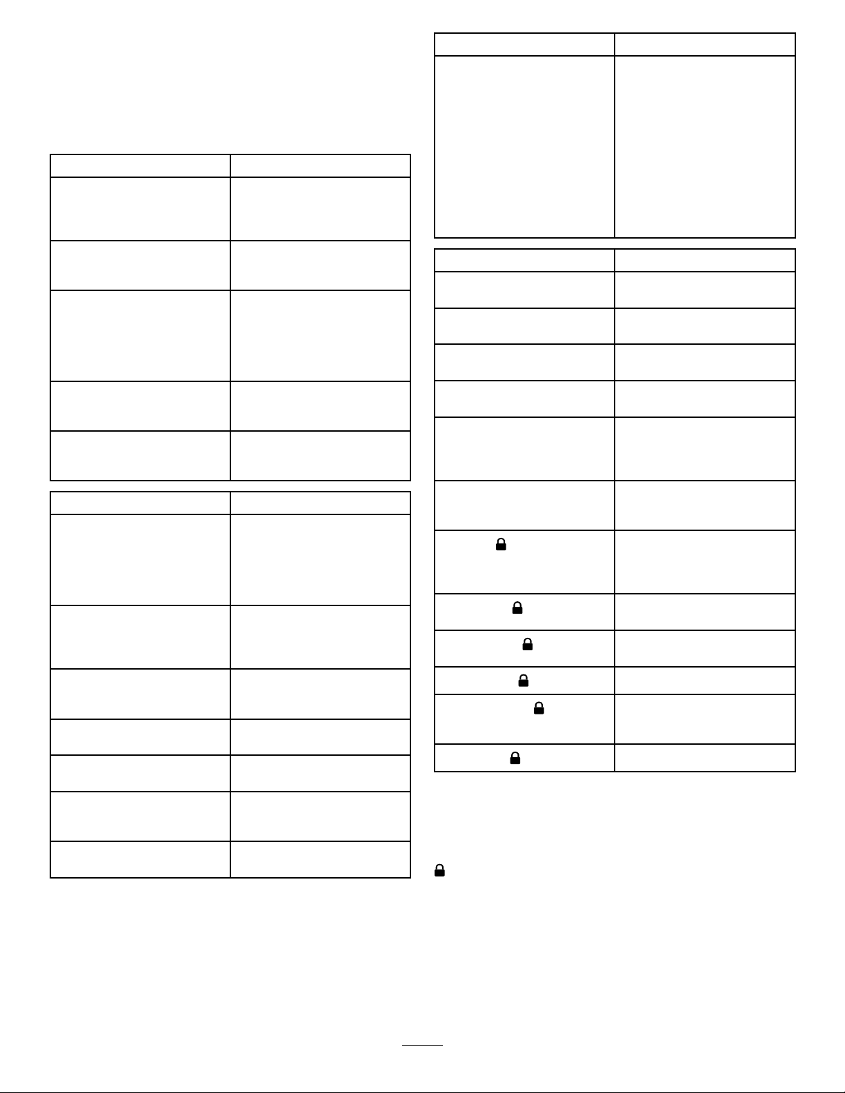
EngineWarningMessages—SootAccumulation
IndicationLevel
FaultCode
Important:Minimizetheamountoftimethatyou
idletheengineoroperatetheengineatlow-engine
speedtohelpreducetheaccumulationofsootin
thesootlter.
DPFSootAccumulation
•Overtime,thedieselparticulatelteraccumulates
sootinthesootlter.Thecomputerfortheengine
monitorsthesootlevelintheDPF .
•Whenenoughsootaccumulates,thecomputer
informsyouthatitistimetoregeneratetheDPF.
•DPFregenerationisaprocessthatheatstheDPF
toconvertthesoottoash.
•Inadditiontothewarningmessages,thecomputer
reducesthepowerproducedbytheengineat
differentsoot-accumulationlevels.
EnginePowerRatingRecommendedAction
Level1:Engine
Level2:Engine
Thecomputerde-ratesthe
Warning
SPN3719,FMI16
Warning
SPN3719,FMI0
g213866
Figure26
CheckEngine
g213867
Figure27
CheckEngine
33
enginepowerto85%.
Thecomputerde-ratesthe
enginepowerto50%.
Performaparkedregeneration
assoonaspossible;refer
toParkedorRecovery
Regeneration(page40).
Performarecoveryregeneration
assoonaspossible;refer
toParkedorRecovery
Regeneration(page40).

DPFAshAccumulation
•Thelighterashisdischargedthroughtheexhaust
system;theheavierashcollectsinthesootlter.
•Ashisaresidueoftheregenerationprocess.Over
time,thedieselparticulatelteraccumulatesash
thatdoesnotdischargewiththeengineexhaust.
•Thecomputerfortheenginecalculatestheamount
ofashaccumulatedintheDPF.
InfoCenterAdvisoryandEngineWarningMessages—AshAccumulation
•Whenenoughashaccumulates,theengine
computersendsinformationtotheInfoCenter
intheformofanenginefaulttoindicatethe
accumulationofashintheDPF .
•Thefaultmessagesindicatethatitistimeto
servicetheDPF.
•Inadditiontothewarnings,thecomputerreduces
thepowerproducedbytheengineatdifferent
ash-accumulationlevels.
Indication
Level1:
Engine
Warning
Level2:
Engine
Warning
Level3:
Engine
Warning
Level
FaultCode
g213863
EngineSpeed
Reduction
None
Figure28
EnginePowerRatingRecommendedAction
Thecomputer
de-ratestheengine
powerto85%.
ServicetheDPF;
refertoServicingthe
Diesel-OxidationCatalyst
(DOC)andtheSoot
Filter(page60)
CheckEngine
SPN3720,FMI16
ServicetheDPF;
refertoServicingthe
Diesel-OxidationCatalyst
(DOC)andtheSoot
Filter(page60)
g213863
Figure29
Thecomputer
None
de-ratestheengine
powerto50%.
CheckEngine
SPN3720,FMI16
ServicetheDPF;
refertoServicingthe
Diesel-OxidationCatalyst
(DOC)andtheSoot
Filter(page60)
g214715
Figure30
Enginespeedat
maximumtorque+
200rpm
Thecomputer
de-ratestheengine
powerto50%.
CheckEngine
SPN3251,FMI0
34

TypesofDieselParticulateFilterRegeneration
Typesofdieselparticulatelterregenerationthatareperformedwhilethemachineisoperating:
TypeofRegenerationConditionsthatcauseDPFregenerationDPFdescriptionofoperation
Passive
Assist
Reset
Occursduringnormaloperationofthemachineat
high-enginespeedorhigh-engineload
Occursbecauseoflow-enginespeed,low-engine
load,orafterthecomputerdetectstheDPFis
becomingobstructedwithsoot
Occursevery100hours
Alsooccursafterassistregenerationonlyifthe
computerdetectsthatassistregenerationdidnot
sufcientlyreducethesootlevel
•TheInfoCenterdoesnotdisplayaniconindicating
passiveregeneration.
•Duringpassiveregeneration,theDPFprocesses
high-heatexhaustgasses,oxidizingharmful
emissions,andburningsoottoash.
Referto(page).
•TheInfoCenterdoesnotdisplayaniconindicating
assistregeneration.
•Duringassistregeneration,theenginecomputer
adjuststheenginesettingstoraisetheexhaust
temperature.
RefertoAssistDPFRegeneration(page38).
•Whenthehighexhaust-temperatureicon
isdisplayedintheInfoCenter,aregenerationisin
progress.
•Duringresetregeneration,theenginecomputer
adjuststheenginesettingstoraisetheexhaust
temperature.
RefertoResetRegeneration(page38).
Typesofdieselparticulatelterregenerationthatrequireyoutoparkthemachine:
TypeofRegenerationConditionsthatcauseDPFregenerationDPFdescriptionofoperation
Parked
Occursbecausethecomputerdetectsback
pressureintheDPFduetosootbuildup
Alsooccursbecausetheoperatorinitiatesaparked
regeneration
MayoccurbecauseyousettheInfoCentertoinhibit
resetregenerationandcontinuedoperatingthe
machine,addingmoresootwhentheDPFalready
needsaresetregeneration
Mayresultfromusingtheincorrectfuelorengineoil
•Whenthereset-standby/parkedorrecovery
regenerationiconorADVISORY#188
displaysintheInfoCenter,aregenerationis
requested.
•Performtheparkedregenerationassoonas
possibletoavoidneedingarecoveryregeneration.
•Aparkedregenerationrequires30to60minutes
tocomplete.
•Youmusthaveatleasta1/4tankoffuelinthe
tank.
•Youmustparkthemachinetoperformaparked
regeneration.
RefertoParkedorRecoveryRegeneration(page
40).
35
Typesofdieselparticulatelterregenerationthatrequireyoutoparkthemachine:(cont'd.)
TypeofRegenerationConditionsthatcauseDPFregenerationDPFdescriptionofoperation
Recovery
Occursbecausetheoperatorignoredrequestsfor
aparkedregenerationandcontinuedoperatingthe
machine,addingmoresoottotheDPF
•Whenthereset-standby/parkedorrecovery
regenerationiconorADVISORY#190
displaysintheInfoCenter,arecoveryregeneration
isrequested.
•Arecoveryregenerationrequiresupto3hours
tocomplete.
•Youmusthaveatleasta1/2tankoffuelinthe
machine.
•Youmustparkthemachinetoperformarecovery
regeneration.
RefertoParkedorRecoveryRegeneration(page
40).
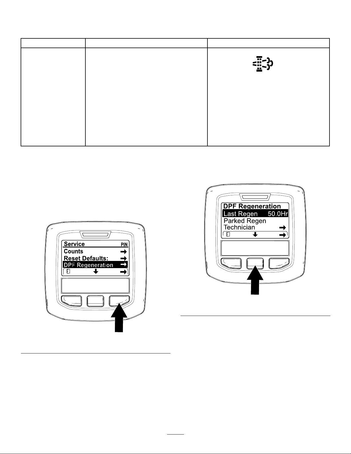
AccessingtheDPFRegeneration
Menus
AccessingtheDPFRegenerationMenus
1.AccesstheServicemenu,pressthecenter
buttontoscrolldowntotheDPFREGENERATION
option(Figure31).
UsetheLASTREGENeldtodeterminehowmany
hoursyouhaveruntheenginesincethelastreset,
parked,orrecoveryregeneration.
g224693
Figure32
Figure31
2.PresstherightbuttontoselecttheDPF
Regenerationentry(Figure31).
TimeSinceLastRegeneration
AccesstheDPFRegenerationmenu,pressthecenter
buttontoscrolldowntotheLASTREGENeld(Figure
32).
g227667
TechnicianMenu
Important:Foroperatingconvenience,you
maydecidetoperformaparkedregeneration
beforethesootloadreaches100%,provided
theenginehasrunmorethan50hourssince
thelastsuccessfulreset,parked,orrecovery
regeneration.
Usethetechnicianmenutoviewthecurrentstateof
engineregenerationcontrolandviewthereported
sootlevel.
AccesstheDPFRegenerationmenu,pressthecenter
buttontoscrolldowntotheTECHNICIANoption,and
36

presstherightbuttontoselecttheT echnicianentry
(Figure33).
DPFOperationTable(cont'd.)
Figure33
•UsetheDPFoperationtabletounderstandthe
currentstateofDPFoperation(Figure34).
State
ResetRegenTheenginecomputerisrunningareset
ParkedStby
ParkedRegenYouinitiatedaparkedregeneration
Recov.Stby
Recov.RegenY ouinitiatedarecoveryregeneration
g227348
•Viewthesootloadwhichismeasuredasthe
percentageofsootintheDPF(Figure35);referto
Description
regeneration.
Theenginecomputerisrequestingthat
yourunaparkedregeneration.
requestandtheenginecomputeris
processingtheregeneration.
Theenginecomputerisrequestingthat
yourunarecoveryregeneration.
requestandtheenginecomputeris
processingtheregeneration.
thesoot-loadtable.
Note:Thesootloadvaluevariesasthemachine
isoperatedandDPFregenerationoccurs.
.
DPFOperationTable
State
NormalTheDPFisinnormal-operating
AssistRegen
ResetStby
Figure34
Description
mode—passiveregeneration.
Theenginecomputerisperformingan
assistregeneration.
Theengine
computeristrying
torunareset
regeneration,but
1ofthefollowing
conditionsprevents
regeneration:
Theregeninhibit
settingissettoON.
Theexhaust
temperature
istoolowfor
regeneration.
g227359
Figure35
Soot-LoadT able
ImportantSootLoadValuesRegenerationState
0%to5%
78%Theenginecomputerperforms
g227360
100%
122%
Minimumsootloadrange
anassistregeneration.
Theenginecomputer
automaticallyrequestsa
parkedregeneration.
Theenginecomputer
automaticallyrequestsa
recoveryregeneration.
PassiveDPFRegeneration
•Passiveregenerationoccursaspartofnormal
engineoperation.
•Whileoperatingthemachine,runtheengineat
full-enginespeedandhighloadwhenpossibleto
promoteDPFregeneration.
37
AssistDPFRegeneration
•Theenginecomputeradjustsenginesettingsto
raisetheexhausttemperature.
•Whileoperatingthemachine,runtheengineat
fullenginespeedandhighloadwhenpossibleto
promoteDPFregeneration.
ResetRegeneration
•TheicondisplaysintheInfoCenterwhilethereset
regenerationisprocessing.
•Wheneverpossible,donotshutofftheengineor
reduceenginespeedwhiletheresetregeneration
isprocessing.
Important:Wheneverpossible,allowthe
machinetocompletetheresetregeneration
processbeforeshuttingofftheengine.
CAUTION
Theexhausttemperatureishot(approximately
600°C(1,112°F)duringDPFregeneration.Hot
exhaustgascanharmyouorotherpeople.
•Neveroperatetheengineinanenclosed
area.
•Makesurethattherearenoammable
materialsaroundtheexhaustsystem.
•Nevertouchahotexhaustsystem
component.
•Neverstandnearoraroundtheexhaust
pipeofthemachine.
PeriodicResetRegeneration
IftheenginehasnotcompletedasuccessfulReset,
Parked,orRecoveryregenerationintheprevious100
hoursofengineoperation,theenginecomputerwill
attempttoperformaresetregeneration.
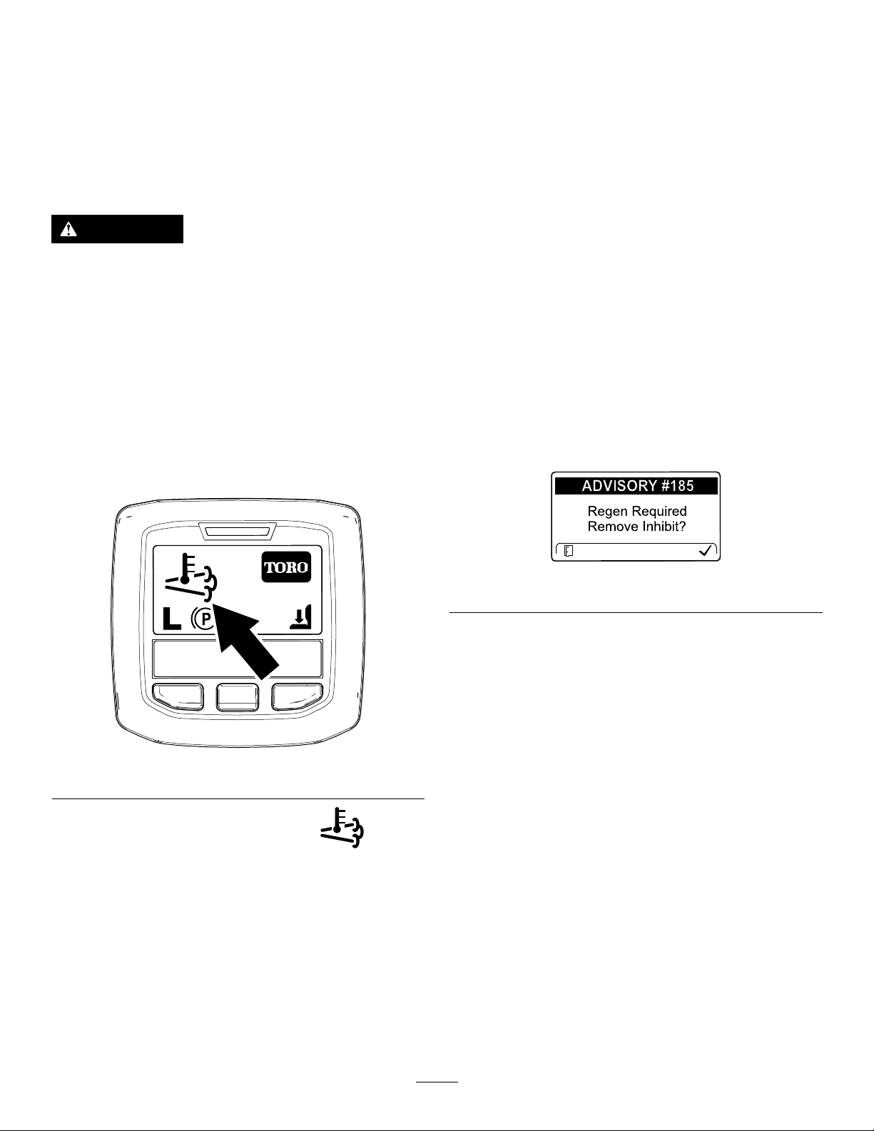
SettingtheInhibitRegen
ResetRegenerationOnly
Note:IfyousettheInfoCentertoinhibitregeneration,
theInfoCenterdisplaysADVISORY#185(Figure37)
every15minuteswhiletheenginerequestsareset
regeneration.
g224692
Figure37
Aresetregenerationproducestheelevatedengine
exhaust.Ifyouareoperatingthemachinearound
trees,brush,tallgrass,orothertemperature-sensitive
plantsormaterials,youcanusetheInhibitRegen
settingtopreventtheenginecomputerfrom
performingaresetregeneration.
Figure36
•Thehighexhaust-temperatureicondisplays
intheInfoCenter(Figure36).
•Theenginecomputeradjustsenginesettingsto
raisetheexhausttemperature.
Important:Thehighexhaust-temperature
iconindicatesthattheexhausttemperature
dischargedfromofyourmachinemaybe
hotterthanduringregularoperation.
•Whileoperatingthemachine,runtheengineat
fullenginespeedandhighloadwhenpossibleto
promoteDPFregeneration.
g224417
Important:Whenyoushutofftheengineand
startitagain,theinhibitregensettingdefaultsto
OFF.
1.AccesstheDPFRegenerationmenu,pressthe
centerbuttontoscrolldowntotheINHIBITREGEN
option,andpresstherightbuttontoselectthe
InhibitRegenentry(Figure38).
38

Figure38
g227304
Figure40
g224394
2.Presstherightbuttontochangetheinhibit
regenerationsettingfromOntoOff(Figure38)
orfromOfftoOn(Figure39).
Figure39
AllowingaResetRegeneration
TheInfoCenterdisplaysthehighexhaust-temperature
icon
whentheresetregenerationisinprocess.
Note:IfINHIBITREGENissettoON,theInfoCenter
displaysADVISORY#185(Figure40).Pressbutton3
tosetinhibitregenerationsettingtoOFFandcontinue
withtheresetregeneration.
Note:Iftheengineexhausttemperatureistoolow,
theInfoCenterdisplaysADVISORY#186(Figure41)to
informyoutosettheenginetofullthrottle(highidle).
g224691
g224395
Figure41
Note:Whentheresetregenerationcompletes,the
highexhaust-temperature
InfoCenterscreen.
disappearsfromthe
39

ParkedorRecoveryRegeneration
•Whentheenginecomputerrequestseithera
parkedregenerationorarecoveryregeneration,
theregenerationrequesticon(Figure42)displays
intheInfoCenter.
Figure42
•Themachinedoesnotautomaticallyperforma
parkedregenerationorarecoveryregeneration,
youmustruntheregenerationthroughthe
InfoCenter.
ParkedRegenerationMessages
regenerationrequired—powertakeoffdisabled
ADVISORY#189(Figure45).
g224398
Figure45
Important:Performaparkedregenerationto
restorethePTOfunction;refertoPreparingto
PerformaParkedorRecoveryRegeneration
(page41)andPerformingaParkedorRecovery
Regeneration(page41).
Note:TheHomescreendisplaysthePTO
disabledIcon(Figure46).
g224404
g224415
Figure46
Whenaparkedregenerationisrequestedbythe
enginecomputerthefollowingmessagesdisplayin
theInfoCenter:
•EnginewarningSPN3720,FMI16(Figure43)
Figure43
•ParkedregenerationrequiredADVISORY#188
(Figure44)
Note:Advisory#188displaysevery15minutes.
Figure44
RecoveryRegenerationMessages
Whenarecoveryregenerationisrequestedbythe
enginecomputer,thefollowingmessagesdisplayin
theInfoCenter:
•EnginewarningSPN3719,FMI0(Figure47)
g213863
g213867
Figure47
•Recoveryregenerationrequired—powertakeoff
disabledADVISORY#190(Figure48)
g224397
•Ifyoudonotperformaparkedregeneration
within2hours,theInfoCenterdisplaysparked
g224399
Figure48
40

Important:Performarecoveryregeneration
torestorethePTOfunction;refertoPreparing
toPerformaParkedorRecoveryRegeneration
(page41)andPerformingaParkedorRecovery
Regeneration(page41).
Note:TheHomescreendisplaysthePTOdisabled
Icon;refertoFigure46inParkedRegeneration
Messages(page40).
DPFStatus-Limitation
•Iftheenginecomputerrequestsarecovery
regenerationorisprocessingarecovery
regenerationandyouscrolldowntothePARKED
REGENoption,parkedregenerationlocksandthe
lockicon(Figure49)appearsinthelowerright
corneroftheInfoCenter.
2.Movethemachineoutsidetoanareaawayfrom
combustiblematerials.
3.Parkthemachineonalevelsurface.
4.Ensurethatthetractioncontrolormotion-control
leversareintheNEUTRALposition.
5.Ifapplicable,shutoffthePTO,andlowerthe
cuttingunitsoraccessories.
6.Engagetheparkingbrake.
7.SetthethrottletothelowIDLEposition.
PerformingaParkedorRecovery
Regeneration
CAUTION
Theexhausttemperatureishot(approximately
600°C(1,112°F)duringDPFregeneration.Hot
exhaustgascanharmyouorotherpeople.
•Neveroperatetheengineinanenclosed
area.
Figure49
•Iftheenginecomputerhasnotrequesteda
recoveryregenerationandyouscrolldown
totheRECOVERYREGENoption,therecovery
regenerationlocksandthelockicon(Figure50)
appearsinthelowerrightcorneroftheInfoCenter.
Figure50
PreparingtoPerformaParkedorRecovery
Regeneration
•Makesurethattherearenoammable
g224625
materialsaroundtheexhaustsystem.
•Nevertouchahotexhaustsystem
component.
•Neverstandnearoraroundtheexhaust
pipeofthemachine.
Important:Thecomputerofthemachinecancels
DPFregenerationifyouincreasetheenginespeed
fromlowidleorreleasetheparkingbrake.
1.AccesstheDPFRegenerationmenu,press
thecenterbuttontoscrolldowntoeitherthe
PARKEDREGENST ARToptionortheRECOVERY
REGENSTARToption(Figure51),andpressthe
rightbuttontoselectthestarttheregeneration
(Figure51).
g224628
1.Ensurethatthemachinehasfuelinthetankfor
thetypeofregenerationyouareperforming:
•ParkedRegeneration:Ensurethatyou
have1/4tankoffuelbeforeperformingthe
parkedregeneration.
•RecoveryRegeneration:Ensurethatyou
have1/2tankoffuelbeforeperformingthe
recoveryregeneration.
41

Figure51
3.AttheDPFchecklistscreen,verifythatthe
parkingbrakeisengagedandthattheengine
speedissettolowidle(Figure53).
g224402
g224407
g224629
2.AttheVERIFYFUELLEVELscreen,verifythatyou
have1/4tankoffuelifyouareperformingthe
parkedregenerationor1/2tankoffuelifyouare
performingtherecoveryregeneration,andpress
therightbuttontocontinue(Figure52).
g227679
Figure53
4.AttheINITIATEDPFREGENscreen,pressthe
rightbuttontocontinue(Figure54).
g224414
g224626
Figure52
g227678
g224630
Figure54
42

5.TheInfoCenterdisplaystheINITIA TINGDPF
REGENmessage(Figure55).
Figure55
6.TheInfoCenterdisplaysthetimetocomplete
message(Figure56).
CheckMessageandCorrectiveActionTable
(cont'd.)
g224411
CorrectiveAction:Startandruntheengine.
g227681
CorrectiveAction:Runtheenginetowarmthecoolant
temperatureto60°C(140°F).
Figure56
7.Theenginecomputercheckstheenginestate
andfaultinformation.TheInfoCentermay
displaythefollowingmessagesfoundinthe
tablethatfollows:
CheckMessageandCorrectiveActionT able
CorrectiveAction:Exittheregenerationmenuandrunthe
machineuntilthetimesincelastregenerationisgreaterthan
50hours;refertoTimeSinceLastRegeneration(page36).
g224406
g224406
CorrectiveAction:Changetheenginespeedtolowidle.
CorrectiveAction:Troubleshoottheenginecomputer
conditionandretryDPFregeneration.
8.TheInfoCenterdisplaysthehomescreenand
theregenerationacknowledgeicon(Figure57)
appearsinthelowerrightcornerofthescreen
astheregenerationprocesses.
g224403
Figure57
CorrectiveAction:Troubleshoottheenginefaultandretry
DPFregeneration.
Note:WhiletheDPFregeneration
runs,theInfoCenterdisplaysthehigh
exhaust-temperatureicon.
9.Whentheenginecomputercompletesa
parkedorrecoveryregeneration,theInfoCenter
43

displaysADVISORY#183(Figure58).Pressthe
leftbuttontoexittothehomescreen.
Figure58
CancelingaParkedorRecoveryRegeneration
UsetheParkedRegenCancelorRecoveryRegen
Cancelsettingtocancelarunningparkedorrecovery
regenerationprocess.
1.AccesstheDPFRegenerationmenu(Figure
60).
g224392
Note:Iftheregenerationfailstocomplete,the
InfoCenterdisplaysAdvisory#184(Figure58).
Presstheleftbuttontoexittothehomescreen.
Figure59
g227305
Figure60
2.Pressthecenterbuttontoscrolldowntothe
PARKEDREGENCANCEL(Figure60)orthe
RECOVERYREGENCANCELoption(Figure61).
g224393
g227306
Figure61
3.PresstherightbuttontoselecttheRegen
Cancelentry(Figure60orFigure61).
44

Understandingthe
Operatingthe
OperatingCharacteristics
oftheMachine
Practicedrivingthemachinebecauseithasa
hydrostatictransmission,anditscharacteristicsare
differentthanmanyturfmaintenancemachines.
SmartPowerpreventsboggingdowninheavyturf
byautomaticallycontrollingthemachinespeedand
optimizingcuttingperformance.
Youcanusethebrakestoassistinturningthe
machine.However,usethemcarefully,especially
onsoftorwetgrassbecausetheturfmaybetorn
accidentally.Thebrakescanalsohelpyoutomaintain
traction.Forexample,onsomeslopes,theuphill
wheelcanslipandlosetraction.Inthissituation,
presstheuphillturnpedalgraduallyandintermittently
untiltheuphillwheelstopsslipping,thusincreasing
tractiononthedownhillwheel.
Useextracarewhenoperatingthemachineonslopes.
Makesurethattheseatlatchisproperlysecured
andthattheseatbeltisbuckled.Driveslowlyand
avoidsharpturnsonslopestopreventrollovers.For
steeringcontrol,lowerthecuttingunitswhengoing
downhill.
Engine-CoolingFan
Theenginecoolingfanisnormallycontrolledbythe
machine.Themachinecanreversethefantoblow
debrisofftherearscreen.Undernormaloperating
conditions,themachinecontrolsthefanspeed
anddirectionbasedoncoolantandhydraulic-uid
temperature,andthefanautomaticallyreverses
directiontoblowdebrisofftherearscreen.Areverse
cycleisautomaticallyinitiatedwheneitherthecoolant
orhydraulic-uidtemperaturereachesaspecic
temperature.
Youcanmanuallyreversethefanbypressingthe2
outerbuttonsoftheInfoCenterfor2seconds—thefan
completesamanuallyinitiatedreversecycle.Reverse
thefanwhentherearscreeniscloggedorpriorto
movingthemachineintotheshoporastoragearea.
Important:Allowtheenginetoidlefor5minutes
beforeshuttingitoffafterafullloadoperation.
Thisallowstheturbochargertocooldownbefore
shuttingtheengineoff.Failuretodosomay
damagetheturbo-charger.
Beforeshuttingofftheengine,disengageallcontrols
andsettheenginespeedtoslowtoreducetheengine
speedtoslowreduceshighenginespeed(rpm),
noise,andvibration.TurnthekeytotheOFFposition
toshutofftheengine.
g036843
g036844
Figure62
45

UsingCruiseControl
Thecruise-controlswitchlocksinthepedalpositionto
maintainthedesiredgroundspeed.Pressingtherear
oftheswitchturnsthecruisecontroloff,themiddle
positionoftheswitchenablesthecruise-control
function,andthefrontoftheswitchsetsthedesired
groundspeed.
Note:Pressingeitherthebrakepedalormovingthe
tractionpedalintotheREVERSEposition,for1second,
alsodisengagesthepedalposition.
UsingtheTransport
OperatingTips
OperatingtheMachine
•Starttheengine.IftheAUTOIDLEfunctionis
turnedoff,runitatHALFIDLEuntilitwarmsup.
RuntheengineatHIGHIDLE,liftthemowerdecks,
disengagetheparkingbrake,presstheforward
tractionpedal,andcarefullydrivetoanopenarea.
•Practicemovingforwardandreverse,andstarting
andstoppingthemachine.Tostopthemachine,
removeyourfootfromthetractionpedalandletit
returntoNEUTRALorpressdownonthereverse
pedal.
Latches
Groundsmaster4700Only
Usethe2rear-transportlatchesfortheNo.6and7
mowerdeckswhenmovingthemachineoverlong
distances,roughterrain,whentransporting,orstoring
themachine.
Note:Whengoingdownhillinthemachine,you
mayneedtousethereversepedaltostop.
•Whenpossible,mowupanddownhillsratherthan
acrossthem.Havethemowerdeckslowered
whengoingdownahilltomaintainsteeringcontrol.
Donotattempttoturnthemachineonahill.
•Practicedrivingaroundobstacleswiththemower
decksupanddown.Becarefulwhendriving
betweennarrowobjectssothatyoudonotdamage
themachineormowerdecks.
•Alwaysdriveslowlyinroughareas.
•Ifanobstacleisintheway ,liftthemowerdecks
tomowaroundit.
•Whentransportingthemachinefrom1workarea
toanother,raisethemowerdeckstothefully
upwardposition,shutoffthePTO,pressthe
mow/transportswitchtotheTRANSPORTposition,
andpressuptheengine-speedswitchtosetthe
enginetohigh-idlespeed.
ChangingMowingPatterns
Figure63
Changemowingpatternsoftentominimizeapoor
after-cutappearancefromrepeatedlymowinginthe
samedirection.
UnderstandingCounterbalance
Thecounterbalancesystemmaintainshydraulic
backpressureonthecuttingunit-liftcylinders.This
counterbalancepressuretransferscutting-unitweight
g038610
tothemachinedrivewheelstoimprovetraction.The
counterbalancepressurehasbeensetatthefactory
toanoptimalbalanceofafter-cutappearanceand
tractioncapabilityinmostturfconditions.Decreasing
thecounterbalancesettingcanproduceamore
stablecuttingunitbutcandecreasethetraction
capability.Increasingthecounterbalancesetting
canincreasethetractioncapability,butmayresult
inapoorafter-cutappearance;refertoSettingthe
Counterbalance(page21).
46

ResolvingAfter-CutAppearance
CheckingtheConditionofthe
RefertotheAfter-cutAppearanceT roubleshooting
Guideavailableatwww.T oro.com.
UsingProperMowingTechniques
•Tobegincutting,engagethemowerdecks,then
approachthemowingareaslowly.Oncethefront
mowerdecksareoverthemowingarea,lowerthe
mowerdecks.
•Toachievetheprofessionalstraight-linecutand
stripingthatisdesirableforsomeapplications,nd
atreeorotherobjectinthedistanceanddrive
straighttowardit.
•Assoonasthefrontmowerdecksreachtheedge
ofthemowingarea,liftthemowerdecks,and
performateardrop-shapedturntoquicklylineup
foryournextpass.
•Bolt-inmulchingbafesareavailableforthe
mowerdecks.Themulchingbafesperformwell
whenyoumaintainturfonaregularschedule
toavoidremovingmorethan25mm(1inch)of
growthpercutting.Whenyoucuttoomuchgrowth
withthemulchingbafesinstalled,theafter-cut
appearancemaydeteriorateandtheobserved
powertocuttheturfincreases.Themulching
bafesalsoperformwellforshreddingleavesin
thefall.
MowingWhentheGrassIsDry
Moweitherinthelatemorningtoavoidthedew,which
causesgrassclumping,orlateafternoontoavoid
thedamagethatdirectsunlightcancauseonthe
sensitive,freshlymowedgrass.
SelectingtheProperHeight-of-Cut
SettingtoSuitConditions
Removenomorethanapproximately25mm(1inch),
or1/3ofthegrassbladewhencutting.Inexceptionally
lushanddensegrass,youmayneedtoraiseyour
height-of-cutsetting.
MowerDeck
Ensurethatthecuttingchambersareingood
condition.Straightenanybendsinthechamber
componentstoensurecorrectbladetip/chamber
clearance.
MaintainingtheMachineafter
Mowing
Aftermowing,thoroughlywashthemachinewitha
gardenhosewithnonozzletoavoidcontamination
anddamagetothesealsandbearingscaused
byexcessivewaterpressure.Ensurethatthe
radiatorandoilcoolerarekeptfreeofdirtorgrass
clippings.Aftercleaning,inspectthemachinefor
possiblehydraulic-uidleaks,damage,orweartothe
hydraulicandmechanicalcomponents,andcheckthe
cutting-unitbladesforsharpness.
UnderstandingTurnaround-Mode
Theturnaround-modeallowsyouconvenient,1-touch
controltoraisethecuttingunitsabovetheturfwhile
temporarilystoppingtheblades,allowingyoutofocus
ondrivingthemachineattheendofamowingpass,
orwhilenavigatingotherobstacles.
•Settheturnaround-modetotheONpositionby
momentarilypressingtheliftswitchrearward
(Figure10),whichautomaticallyraisesallcutting
unitsfromtheoatpositiontoapresetheightand
disengagesthePTO.Toresumemowing,press
theliftswitchforward.Allcuttingunitslower,and
thePTOstartagain.
•Settingtheturnaround-modetotheOFFposition
allowsyoutomanuallyraisethecuttingunits
fromtheoatpositionbypressingandholding
allliftswitchesrearwarduntilthecuttingunits
raisetothedesiredheight.ForGroundsmaster
4700machines,pressall3liftswitchestoraise
all7cuttingunits(Figure10).ThePTOdoesnot
disengageuntilthecuttingunitsraisetothesame
presetheighttowhichthecuttingunitsraisewhen
theturnaround-modeissettoON.
MowingwithSharpBlades
Asharpbladecutscleanlyandwithouttearingor
shreddingthegrassbladeslikeadullblade.Tearing
andshreddingcausesthegrasstoturnbrownat
theedges,whichimpairsgrowthandincreases
susceptibilitytodiseases.Ensurethatthebladeisin
goodconditionandthatthereisafullsail.
Note:Thedefaulttheturnaround-modefeatureisON.
47

AfterOperation
SecuringtheCuttingUnits
1.EnsurethatthePTOisdisengaged.
AfterOperationSafety
•Cleangrassanddebrisfromthecuttingunits,
mufers,andenginecompartmenttohelpprevent
res.Cleanupoilorfuelspills.
•Ifthecuttingunitsareinthetransportposition,use
thepositivemechanicallock(ifavailable)before
youleavethemachineunattended.
•Allowtheenginetocoolbeforestoringthemachine
inanyenclosure.
•Shutoffthefuelbeforestoringortransportingthe
machine.
•Neverstorethemachineorfuelcontainerwhere
thereisanopename,spark,orpilotlight,such
asonawaterheateroronotherappliances.
•Keepallpartsofthemachineingoodworking
conditionandallhardwaretightened,especially
blade-attachmenthardware.
•Replaceallwornordamageddecals.
UsingtheCutting-Unit
2.Parkthemachineonalevelsurface.
3.Engagetheparkingbrake.
4.Fullyraisethecuttingunits.
5.Alignthelanyardtothecarriershaftofthelift
armfortheforwardouter-cuttingunit(Figure65).
StorageLanyard
Usethecutting-unitstoragelanyardstopreventthe
forwardoutercuttingunitsfromsettlingwhenthe
machineisparkedovernightorifitisbeingstoredfor
anextensiveperiod.Youcanalsousethecutting-unit
storagelanyardstopreventthecuttingunitsfrom
oatingwhilethemachineistransportingbetween
mowingtasks.
Figure65
1.Carrier-shaftgroove
(forwardouter-liftarm)
6.Sliptheloopinthelanyardoverthecarriershaft
untilthelanyardisfullyseatedinthegroovein
theshaft(Figure65).
7.Repeatsteps5and6fortheforward
outer-cuttingunitattheothersideofthe
machine.
2.Lanyardloop
Important:Removethelanyardsfromthecarrier
shaftsbeforeloweringthecuttingunits
StowingtheLanyards
Note:Stowthelanyardswhenyouarenotusing
them.
g225483
Figure64
g225484
1.EnsurethatthePTOisdisengaged.
2.Parkthemachineonalevelsurface.
3.Engagetheparkingbrake.
48
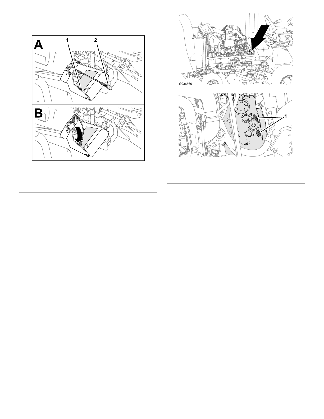
4.Withthecuttingunitslowered,sliptheloopof
thelanyardintotheslotinthereinforcement
plateoftherollersupport(Figure66).
g036666
Figure66
1.Reinforcement-plateslot
(rollersupport)
2.Lanyardloop
HaulingtheMachine
•Usecarewhenloadingorunloadingthemachine
intoatraileroratruck.
•Usefull-widthrampsforloadingthemachineinto
atraileroratruck.
•Tiethemachinedownsecurely.
PushingorTowingthe Machine
Inanemergency,themachinecanbemoved
forwardbyactuatingthebypassvalveinthe
variable-displacementhydraulicpumpandpushingor
towingthemachine.
g225485
1.Bypassvalves
2.Rotateeachvalve3turnscounter-clockwiseto
openandallowtheoiltobypassinternally.
Figure67
g225685
Note:Donotopenmorethan3turns.Because
uidisbypassed,youcanslowlymovethe
machinewithoutdamagingthetransmission.
3.Closethebypassvalvesbeforestartingthe
engine.
4.Torqueto70N∙m(52ft-lb)toclosethevalve.
Important:Topushortowthemachineinreverse,
youmustbypassthecheckvalveinthe4-wheel
drivemanifold.Tobypassthecheckvalve,
connectahoseassemblytothereversetraction
pressuretestport,locatedonthehydrostat,and
ontheportlocatedbetweenportsM8andP2on
thereartractionmanifold,whichislocatedbehind
thefronttire.Thehoseassemblyincludes1hose
(PartNo.95-8843),2couplerttings(PartNo.
95-0985),and2hydraulicttings(PartNo.340-77).
Important:Donotpushortowthemachine
fasterthan3to4.8km/h(2to3mph),because
youmaydamagethetransmission.Thebypass
valvesmustbeopenwheneveryoupushortow
themachine.
1.Openthehoodandlocatethebypassvalves
(Figure67)onthetopofpump,behindthe
batteryandstorageboxes.
49

LocatingtheTie-Down Points
Note:Useproperly-ratedDOT-approvedstrapsin4
cornerstotiedownthemachine.
•Oneachsideoftheframebytheoperator’s
platform
•Ontherearbumper
Figure68
g208989
Figure69
g036665
50

Maintenance
Important:Refertoyourengineowner’smanualforadditionalmaintenanceprocedures.
Important:Ifyouareperformingmaintenanceonthemachineandruntheenginewithanengine
exhaust-extractionduct,settheinhibitregensettingtoON;refertoSettingtheInhibitRegen(page38).
Note:Downloadafreecopyoftheelectricalorhydraulicschematicbyvisitingwww.Toro.comandsearching
foryourmachinefromtheManualslinkonthehomepage.
Note:Determinetheleftandrightsidesofthemachinefromthenormaloperatingposition.
RecommendedMaintenanceSchedule(s)
MaintenanceService
Interval
Afterthersthour
Aftertherst10hours
Aftertherst50hours
Aftertherst200hours
Beforeeachuseordaily
Every50hours
MaintenanceProcedure
•Torquethewheellugnuts.
•Torquethewheellugnuts.
•Changetheengineoilandlter.
•Changethefrontplanetary-gearoil.
•Changetherear-axlelubricant.
•Changethehydrauliclters.
•Checkthetirepressure.
•Checktheinterlockswitches.
•Checkthebladestoppingtime.
•Checktheengine-oillevel.
•Drainwaterorothercontaminantsfromthewaterseparator.
•Drainwaterorothercontaminantsfromthefuellter/waterseparator
•Checktherearaxleandrear-axlegearboxforleaks.
•Checklevelofcoolantatthebeginningofeachday.
•Removedebrisfromtheenginearea,oilcooler,andradiator(cleanthemmore
frequentlyindirtyconditions).
•Checkthehydraulic-uidlevel.
•Inspectthehydrauliclinesandhosesforleaks,kinkedlines,loosemounting
supports,wear,loosettings,weatherdeterioration,andchemicaldeterioration.
•Greasethebearingsandbushings(alsoaftereverywashing).
•Checkthebatterycondition.
Every100hours
Every200hours
Every250hours
Every400hours
Every800hours
•Checktheconditionandtensionofthealternatorbelt.
•Torquethewheellugnuts.
•Changetheengineoilandlter.
•Servicetheaircleaner(earlieriftheaircleanerindicatorshowsred,andmore
frequentlyinextremelydirtyordustyconditions).
•Inspectthefuellinesandconnections.
•Replacethefuel-ltercanister.
•Replacetheenginefuellter.
•Checkforend-playintheplanetarydrives.
•Checktheplanetary-gear-driveoillevel(checkifyounoticeexternalleakage).
•Checktherear-axlelubricant.
•Checktherear-axle-gear-boxlubricant.
•Drainandcleanthefueltank.
•Changethefrontplanetary-gearoiloryearly,whichevercomesrst.
•Changetherear-axlelubricant.
•Checktherearwheeltoe-in.
•Changethehydraulicuid.
•Changethehydrauliclters.
51

MaintenanceService
Every6,000hours
Beforestorage
Interval
MaintenanceProcedure
•Disassemble,clean,andassemblethesootlteroftheDPForcleanthesootlter
ifenginefaultsSPN3251FMI0,SPN3720FMI0,orSPN3720FMI16displayinthe
InfoCenter.
•Drainandcleanthefueltank.
•Checkthetirepressure.
•Checkallfasteners.
•Greaseoroilallgreasettingsandpivotpoints.
•Paintchippedsurfaces.
Yearly
•Inspectthefuellinesandconnections.
CAUTION
Ifyouleavethekeyinthekeyswitch,someonecouldaccidentlystarttheengineandseriously
injureyouorotherbystanders.
Removethekeybeforeyoudoanymaintenance.
DailyMaintenanceChecklist
Duplicatethispageforroutineuse.
Fortheweekof:
MaintenanceCheckItem
Checkthesafety-interlock
operation.
Checkthebrakeoperation.
Checktheengine-oillevel.
Checkthe
cooling-system-uidlevel.
Drainthewater/fuel
separator.
Checktheairlter,dustcup,
andburpvalve.
Checkforunusualengine
1
noises.
Checktheradiatorand
screenfordebris
Checkforunusualoperating
noises.
Checkthehydraulic-uid
level.
Checkthehydraulichoses
fordamage.
Checkforuidleaks.
Checkthefuellevel.
Checkthetirepressure.
Checktheinstrument
operation.
Checktheheight-of-cut
adjustment.
MondayTuesdayWednesdayThursdayFriday
SaturdaySunday
52
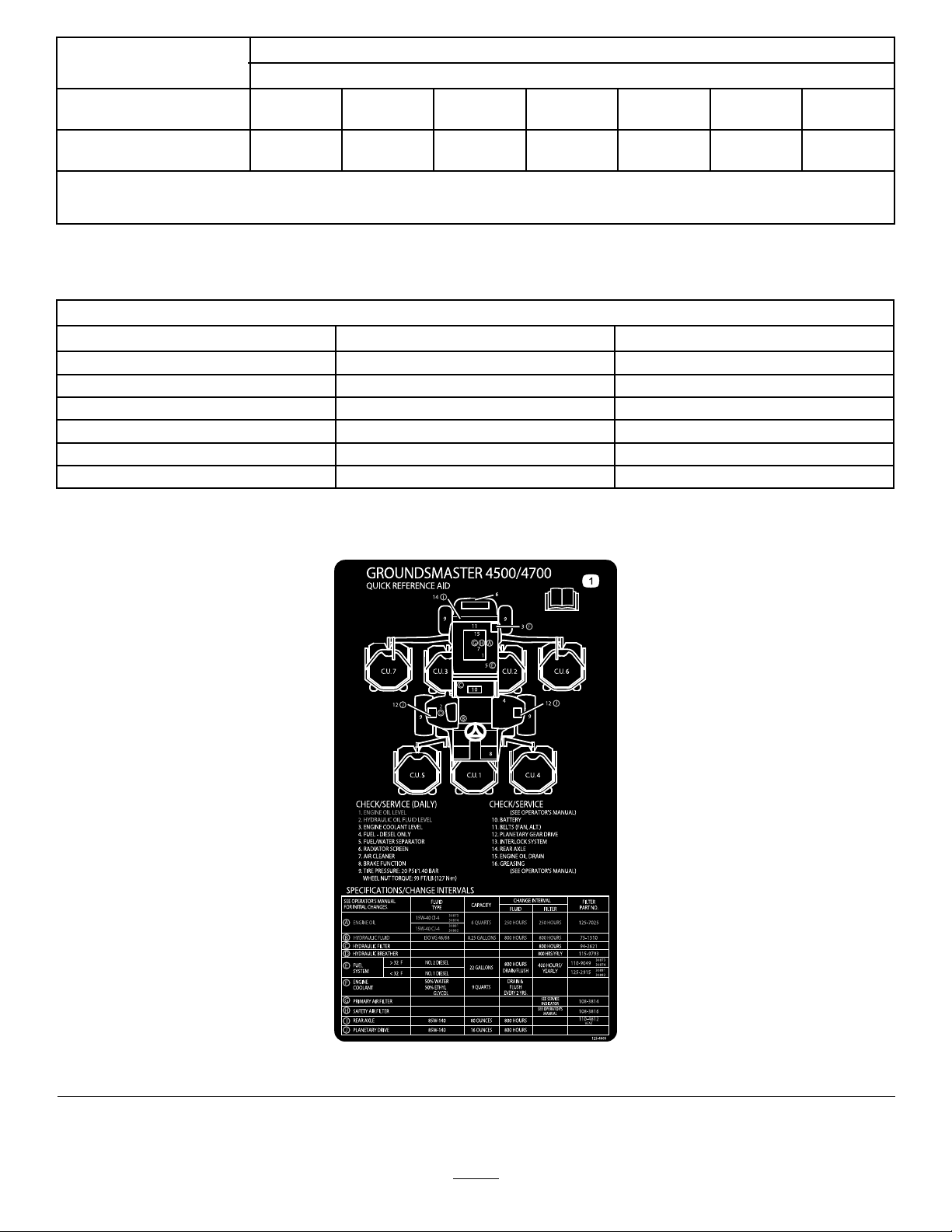
Fortheweekof:
MaintenanceCheckItem
Lubricateallthegrease
2
ttings.
Touchupanydamaged
paint.
1
Checktheglowplugandinjectornozzlesifstartingishard,thereisexcesssmoke,orroughrunningisnoted.
2
Immediatelyaftereverywashing,regardlessoftheintervallisted.
MondayTuesdayWednesdayThursdayFriday
Important:Refertoyourengineoperator’smanualforadditionalmaintenanceprocedures.
NotationforAreasofConcern
Inspectionperformedby:
ItemDate
SaturdaySunday
Information
ServiceIntervalChart
Figure70
decal125-4606
53
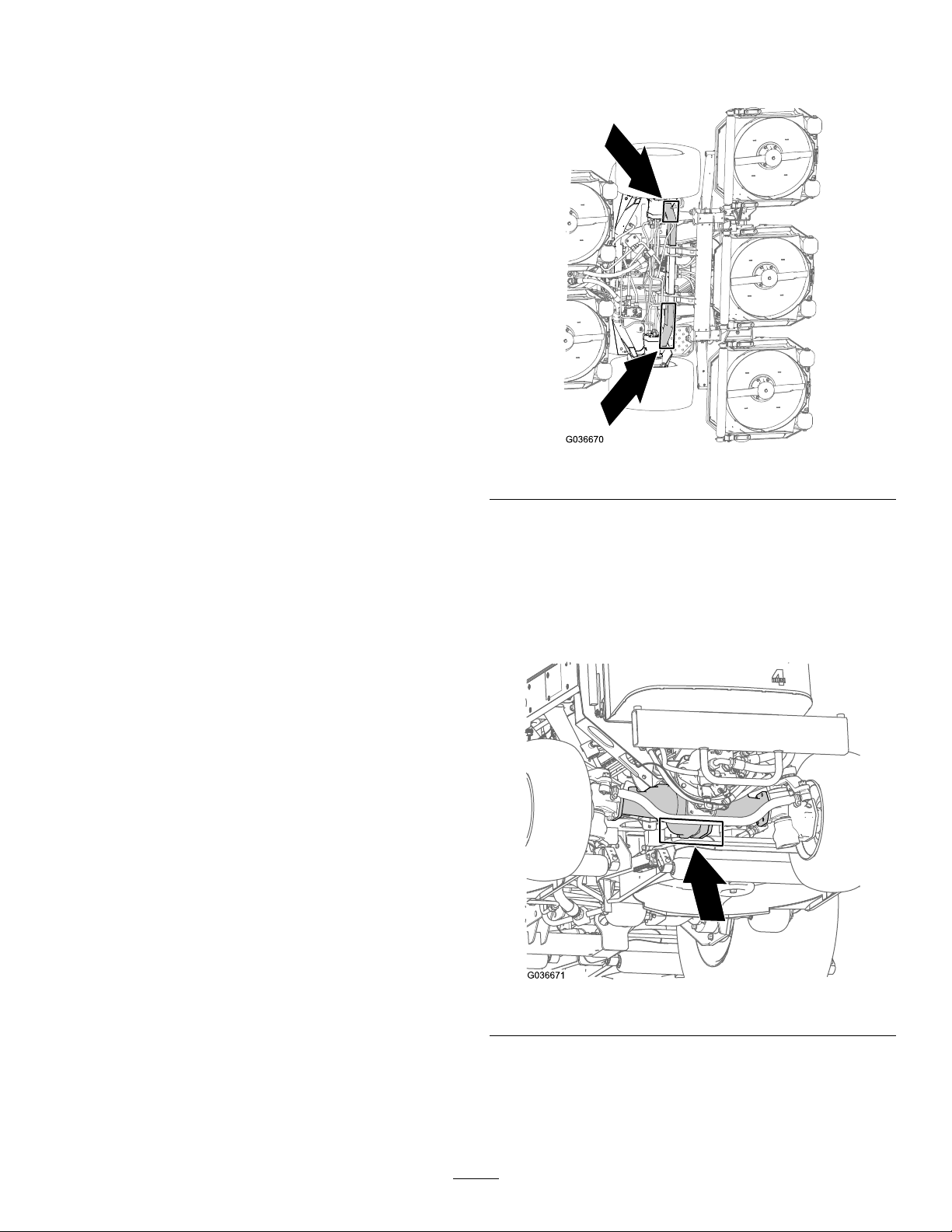
Pre-Maintenance
Procedures
Pre-MaintenanceSafety
•Beforeadjusting,cleaning,repairing,orleaving
themachine,dothefollowing:
–Parkthemachineonalevelsurface.
–Pressdownandholdtheengine-speedswitch
tosettheenginetolow-idlespeed.
–Disengageandlowerthecuttingunits.
–Ensurethatthetractionisinneutral.
–Engagetheparkingbrake.
–Shutofftheengineandremovethekey .
–Waitforallmovingpartstostop.
Important:Donotsupportthemachineatthe
wheel-drivemotors.Keeptheliftingequipment
clearofhydraulictubingandhoses.
–Allowmachinecomponentstocoolbefore
performingmaintenance.
•Ifthecuttingunitsareinthetransportposition,
usethepositivemechanicallockandthestorage
lanyards(ifavailable)beforeyouleavethe
machineunattended.
•Ifpossible,donotperformmaintenancewhilethe
engineisrunning.Keepawayfrommovingparts.
•Usejackstandstosupportthemachineor
componentswhenrequired.
•Carefullyreleasepressurefromcomponentswith
storedenergy.
PreparingtheMachinefor Maintenance
1.EnsurethatthePTOisdisengaged.
2.Parkthemachineonalevelsurface.
3.Engagetheparkingbrake.
4.Lowerthecuttingunit(s)ifnecessary.
g036670
Figure71
Rearofthemachine—atthecenteroftheaxle
(Figure72)
Locatethejackstandsofthespeciedcapacityatboth
sidesofthegearcaseandundertheaxle.
Important:Donotsupportthemachineatthetie
rod.
5.Shutofftheengineandwaitforallmovingparts
tostop.
6.TurnthekeytotheSTOPpositionandremoveit.
7.Allowmachinecomponentstocoolbefore
performingmaintenance.
LiftingtheMachine
Usethefollowingaspointstoliftthemachine:
Frontofthemachine—attheframeofthemachine,
forwardofthewheel-drivemotors(Figure71)
g036671
Figure72
54

OpeningtheHood
AccessingtheHydraulic
TiltthehoodtoaccessthechassisasshowninFigure
73.
LiftCompartment
Tilttheseattoaccessthehydraulicliftcompartment
asshowninFigure74.
Figure73
g036674
Figure74
g036706
55

Lubrication
GreasingtheBearingsand Bushings
ServiceInterval:Every50hours(alsoafterevery
washing).
Greasespecication:No.2lithiumgrease
Thegreasettinglocationsandquantitiesareas
follows:
•Brake-shaftpivotbearings(5)asshowninFigure
75
•Steering-cylinderballjoints(2)asshowninFigure
77
Figure75
•Rear-axle-pivotbushings(2)asshowninFigure
76)
g009706
Figure77
g009704
1.Topttingonkingpin
•Tie-rodballjoints(2)asshowninFigure77
•Kingpinbushings(2)asshowninFigure77
Important:Lubricatethetopttingonthe
kingpinnomorethanannually(2pumps).
•Lift-armbushings(1percuttingunit)asshownin
Figure78
Figure76
g009705
g009707
Figure78
•Lift-cylinderbushings(2percuttingunit)asshown
inFigure78
56
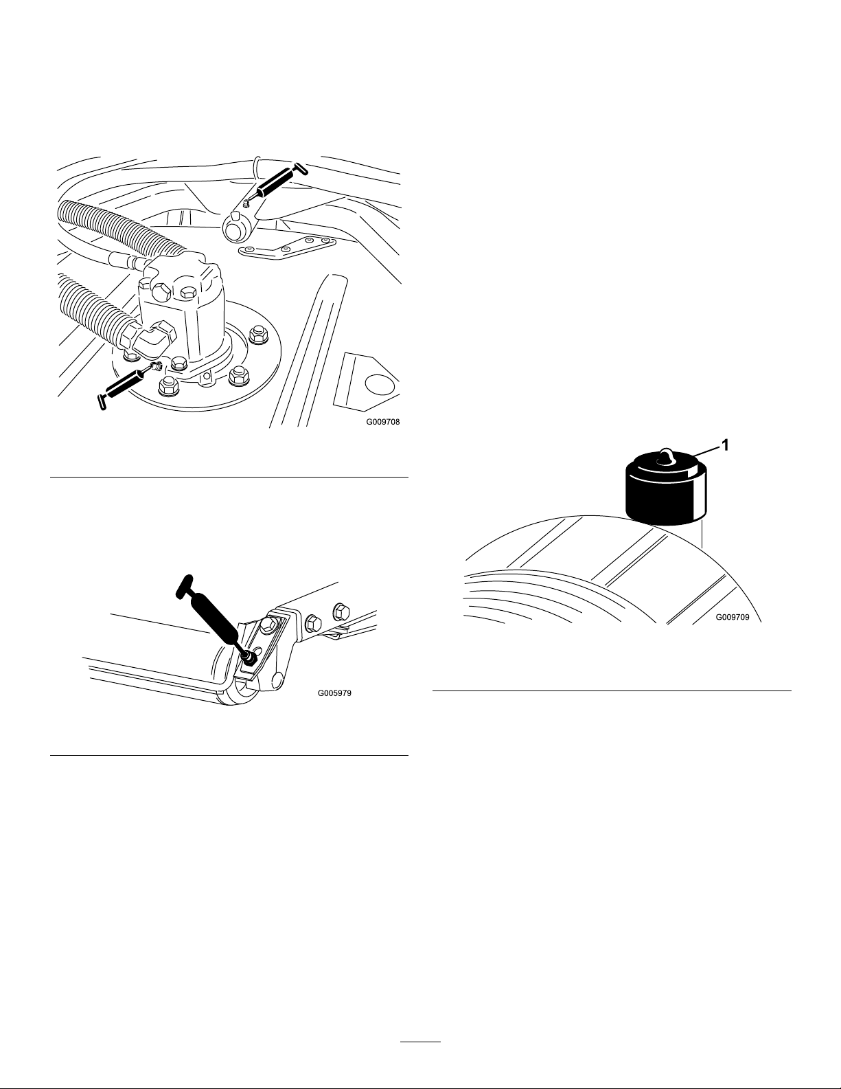
•Cutting-unitspindle-shaftbearings(2percutting
unit)asshowninFigure79
Note:Youcanuseeithertting,whicheveris
moreaccessible.Pumpgreaseintothetting
untilasmallamountappearsatthebottomofthe
spindlehousing(underthecuttingunit).
Figure79
EngineMaintenance
EngineSafety
•Shutofftheenginebeforecheckingtheoilor
addingoiltothecrankcase.
•Donotchangethegovernorspeedoroverspeed
theengine.
ServicingtheAirCleaner
ServiceInterval:Every400hours
Checktheair-cleanerbodyfordamagewhichcould
causeanairleak.Replaceitifitisdamaged.Check
thewholeintakesystemforleaks,damage,orloose
hoseclamps.
Servicetheair-cleanerlteronlywhentheservice
indicator(Figure81)requiresit.Changingtheairlter
beforeitisnecessaryonlyincreasesthechanceof
dirtenteringtheenginewhenyouremovethelter.
g009708
•Cutting-unitcarrier-armbushings(1percutting
unit)asshowninFigure79
•Rearrollerbearings(2percuttingunit)asshown
inFigure80
Figure80
Important:Makesurethatthegreasegroove
ineachrollermountalignswiththegrease
holeineachendoftherollershaft.Tohelp
alignthegrooveandthehole,thereisalsoan
alignmentmarkon1endoftherollershaft.
g009709
Figure81
1.Air-cleanerindicator
g005979
Important:Besurethatthecoverisseated
correctlyandsealswiththeair-cleanerbody.
1.Replacetheaircleaner(Figure82).
57

g198631
g009712
Figure83
1.Air-cleanersafetylter
2.Resettheindicator(Figure81)ifitshowsred.
ServicingtheEngineOil
OilSpecication
Usehigh-quality,low-ashengineoilthatmeetsor
exceedsthefollowingspecications:
•APIservicecategoryCJ-4orhigher
•ACEAservicecategoryE6
•JASOservicecategoryDH-2
Figure82
Note:Donotcleanausedelementbecause
cleaningitcandamagetheltermedia.
Important:Neverattempttocleanthesafety
lter(Figure83).Replacethesafetylter
afterevery3primarylterservices.
Important:UsingengineoilotherthanAPICJ-4
orhigher,ACEAE6,orJASODH-2maycausethe
dieselparticulateltertoplugorcauseengine
damage.
Usethefollowingengineoilviscositygrade:
•Preferredoil:SAE15W-40(above0°F)
•Alternateoil:SAE10W-30or5W-30(all
temperatures)
ToroPremiumEngineOilisavailablefromyour
AuthorizedT oroDistributorineither15W-40or
10W-30viscositygrades.Seethepartscatalogfor
g031861
partnumbers.
CheckingtheEngine-OilLevel
ServiceInterval:Beforeeachuseordaily
Theengineisshippedwithoilinthecrankcase;
however,theoillevelmustbecheckedbeforeand
aftertheengineisrststarted.
Important:Checktheengineoildaily.Ifthe
engine-oillevelisabovetheFullmarkonthe
dipstick,theengineoilmaybedilutedwithfuel;
58

IftheengineoillevelisabovetheFullmark,
changetheengineoil.
Thebesttimetochecktheengineoiliswhenthe
engineiscoolbeforeithasbeenstartedfortheday.
Ifithasalreadybeenrun,allowtheoiltodrainback
downtothesumpforatleast10minutesbefore
checking.IftheoillevelisatorbelowtheAddmark
onthedipstick,addoiltobringtheoilleveltotheFull
mark.Donotoverlltheenginewithoil.
Important:Keeptheengineoillevelbetweenthe
upperandlowerlimitsonthedipstick;theengine
mayfailifyourunitwithtoomuchortoolittleoil.
1.Parkthemachineonalevelsurface.
2.Checktheengine-oillevel(Figure84).
CrankcaseOilCapacity
Approximately5.7L(6USqt)withthelter.
ChangingtheEngineOilandFilter
ServiceInterval:Aftertherst50hours
Every250hours
1.Starttheengineandletitrun5minutestoallow
theoiltowarmup.
2.Withthemachineparkedonalevelsurface,
shutofftheengine,removethekey ,andwait
forallmovingpartstostopbeforeleavingthe
operatingposition.
3.Replacetheengineoilandlter(Figure85).
Figure84
g198647
g031675
Figure85
4.Addoiltothecrankcase.
g031256
Note:Whenusingdifferentoil,drainalloldoil
fromthecrankcasebeforeaddingnewoil.
59

Servicingthe
FuelSystem
Diesel-OxidationCatalyst
(DOC)andtheSootFilter
ServiceInterval:Every6,000hours—Disassemble,
clean,andassemblethesootlter
oftheDPForcleanthesootlterif
enginefaultsSPN3251FMI0,SPN
3720FMI0,orSPN3720FMI16
displayintheInfoCenter.
IfenginefaultsCHECKENGINESPN3251FMI0,CHECK
ENGINESPN3720FMI0,orCHECKENGINESPN3720FMI
16displayintheInfoCenter(Figure86),cleanthesoot
lterusingthestepsthatfollow:
Maintenance
DANGER
Undercertainconditions,dieselfuelandfuel
vaporsarehighlyammableandexplosive.A
reorexplosionfromfuelcanburnyouand
othersandcancausepropertydamage.
•Useafunneltollthefueltankoutdoors,
inanopenarea,whentheengineisoffand
iscold.Wipeupanyfuelthatspills.
•Donotllthefueltankcompletelyfull.
Addfueltothefueltankuntilthelevelis6
to13mm(1/4to1/2inch)belowthebottom
ofthellerneck.Thisemptyspaceinthe
tankallowsthefueltoexpand.
g214715
•Neversmokewhenhandlingfuel,andstay
awayfromanopenameorwherefuel
fumesmaybeignitedbyaspark.
•Storefuelinaclean,safety-approved
containerandkeepthecapinplace.
Figure86
1.RefertotheEnginesectionintheService
Manualforinformationondisassemblingand
assemblingthediesel-oxidationcatalystandthe
sootlteroftheDPF .
2.RefertoyourauthorizedTorodistributorfor
diesel-oxidationcatalystandthesootlter
replacementpartsorservice.
3.ContactyourauthorizedT orodistributortoreset
theengineECUafteryouinstallacleanDPF .
g213864
DrainingtheFuelTank
ServiceInterval:Every800hours—Drainandclean
thefueltank.
g213863
Beforestorage—Drainandcleanthefueltank.
Drainandcleanthetankalsoifthefuelsystem
becomescontaminatedorifyouarestoringthe
machineforanextendedperiod.Usecleanfuelto
ushoutthetank.
InspectingtheFuelLines andConnections
ServiceInterval:Every400hours
Yearly
Inspectthefuellinesandconnectionsfordeterioration,
damage,orlooseconnections.
60

ServicingtheFuel-Water
ReplacingtheFuel-FilterCanister
Separator
Figure87
DrainingWaterfromtheFuel/Water
Separator
ServiceInterval:Beforeeachuseordaily—Drain
waterorothercontaminantsfrom
thefuellter/waterseparator
Drainwaterfromthefuel/waterseparatorasshown
in(Figure88).
ServiceInterval:Every400hours—Replacethe
fuel-ltercanister.
Replacethefuel-ltercanisterasshowninFigure89.
g198661
Figure88
g031412
Figure89
g225506
61

ServicingtheFuelFilter
ServiceInterval:Every400hours
1.Cleantheareaaroundthefuel-lterhead
(Figure90).
g036687
Figure91
Figure90
1.Fuel-lterhead2.Fuellter
2.Removethelterandcleanthelterhead
mountingsurface(Figure90).
3.Lubricatetheltergasketwithcleanlubricating
engineoil;refertotheengineowner'smanual
foradditionalinformation.
4.Installthedryltercanister,byhand,untilthe
gasketcontactsthelterhead,thenrotateitan
additional1/2turn.
5.Starttheengineandcheckforfuelleaksaround
thelterhead.
1.Fitting(fuel-pickuptube)
2.Hoseclamp
3.Fuelsupplyhose
2.Separatethehosefromthetting(Figure91).
g028799
3.Liftthefuel-pickuptubefromthefueltank
(Figure91).
4.Rubberbushing
5.Screen
Note:Liftthetubestraightfromthebushingin
thetank.
4.Cleananydebrisfromthescreenattheendof
thefuel-pickuptube(Figure91).
5.Insertthefuel-pickuptubethroughtherubber
bushingandintothetank(Figure91).
Note:Ensurethatthefuel-pickuptubeisfully
seatedintotherubberbushing.
6.Installthesupplyhoseontothettingofthe
fuel-pickuptube,andsecurethehosewiththe
hoseclampthatyouremovedinstep1.
CleaningtheFuel-Pickup TubeScreen
Thefuel-pickuptube,locatedinsidethefueltank,is
equippedwithascreentohelppreventdebrisfrom
enteringthefuelsystem.Removethefuel-pickuptube
andcleanthescreenasrequired.
1.Removethehoseclampthatsecuresthefuel
supplyhosetothettingofthefuel-pickuptube
(Figure91).
PrimingtheFuelSystem
Primethefuelsystembeforestartingtheenginefor
thersttime,afterrunningoutoffuel,orafterfuel
systemmaintenance(e.g.,drainingthelter/water
separator,replacingafuelhose).
Toprimethefuelsystem,performthefollowingsteps:
1.Ensurethatfuelisinthefueltank.
2.TurntheignitionkeytotheONpositionfor10
to15seconds.
Note:Thisallowsthefuelpumptoprimethe
fuelsystem.
Important:Donotusetheenginestartermotorto
cranktheenginetoprimethefuelsystem.
62

ElectricalSystem
ChargingandConnecting
Maintenance
ElectricalSystemSafety
•Disconnectthebatterybeforerepairingthe
machine.Disconnectthenegativeterminalrst
andthepositivelast.Connectthepositiveterminal
rstandthenegativelast.
•Chargethebatteryinanopen,well-ventilated
area,awayfromsparksandames.Unplugthe
chargerbeforeconnectingordisconnectingthe
battery.Wearprotectiveclothinganduseinsulated
tools.
CheckingtheBattery Condition
ServiceInterval:Every50hours
Important:Beforeweldingonthemachine,
disconnectthenegativecablefromthebatteryto
preventdamagetotheelectricalsystem.Also,
youmustdisconnecttheengine,InfoCenter,
andmachinecontrollersbeforeweldingonthe
machine.
theBattery
1.Unlatchandraisetheoperator'sconsolepanel
(Figure92).
Figure92
1.Operator'sconsolepanel
2.Latch
g009985
Note:Keeptheterminalsandtheentirebatterycase
clean,becauseadirtybatterydischargesslowly.T o
cleanthebattery,washtheentirecasewithasolution
ofbakingsodaandwater.Rinsewithclearwater.
Coatthebatterypostsandcableconnectorswith
Grafo112X(skin-over)grease(T oroPartNo.505-47)
orpetroleumjellytopreventcorrosion.
DANGER
Batteryelectrolytecontainssulfuricacid,
whichisfatalifconsumedandcauses
severeburns.
•Donotdrinkelectrolyteandavoid
contactwithskin,eyes,orclothing.
Wearsafetyglassestoshieldyour
eyesandrubberglovestoprotect
yourhands.
•Fillthebatterywherecleanwateris
alwaysavailableforushingtheskin.
2.Removetherubberbootfromthepositive
terminalandinspectthebattery.
3.Removethenegativecable(black)fromthe
negative(-)terminalandthepositivecable(red)
fromthepositive(+)terminalofthebattery
(Figure93).
63

WARNING
WARNING
Incorrectbatterycableroutingcould
damagethemachineandcables,causing
sparks.Sparkscancausethebattery
gassestoexplode,resultinginpersonal
injury.
•Alwaysdisconnectthenegative
(black)batterycablebefore
disconnectingthepositive(red)
cable.
•Alwaysconnectthepositive(red)
batterycablebeforeconnectingthe
negative(black)cable.
WARNING
Batteryterminalsormetaltoolscould
shortagainstmetalcomponents,causing
sparks.Sparkscancausethebattery
gassestoexplode,resultinginpersonal
injury.
•Whenremovingorinstallingthe
battery,donotallowthebattery
terminalstotouchanymetalpartsof
themachine.
•Donotallowmetaltoolstoshort
betweenthebatteryterminalsand
metalpartsofthemachine.
Chargingthebatteryproducesgasses
thatcanexplode.
Neversmokenearthebatteryandkeep
sparksandamesawayfrombattery.
5.Whenthebatteryischarged,disconnectthe
chargerfromthepoweroutletandbatteryposts.
6.Installthepositivecable(red)tothepositive(+)
terminalandthenegativecable(black)tothe
negative(-)terminalofthebattery(Figure93).
7.Securethecablestothepostswithboltsand
nuts.
Note:Makesurethatthepositive(+)terminal
isallthewayonthepostandthecableis
positionedsnugtothebattery.Thecablemust
notcontactthebatterycover.
8.CoatbothbatteryconnectionswithGrafo112X
(skin-over)grease,PartNo.505-47,petroleum
jelly,orlightgreasetopreventcorrosion.
9.Slidetherubberbootoverthepositiveterminal.
10.Closetheconsolepanelandsecurethelatch.
LocatingtheFuses
Thefuseblockforthemachineislocatedintheright
storagebox
Figure93
1.Positivebatterycable2.Negativebatterycable
4.Connecta3to4Abatterychargertothebattery
posts.Chargethebatteryatarateof3to4Afor
4to8hours.
g009986
1.Loosenthelatchforthecoveroftheright
storageboxandraisethecover(Figure95)to
exposethefuseblock(Figure96).
64
Figure94
decal125-4605
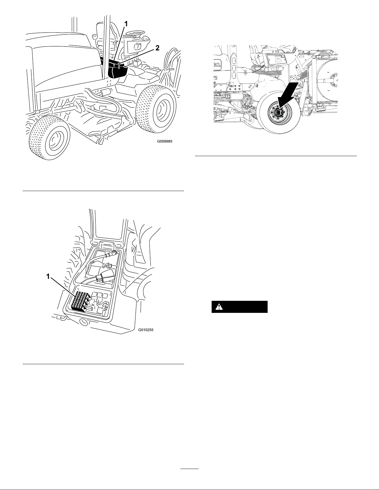
Figure95
1.Latch2.Rightstoragebox
2.Replacetheopenfuse(s)asneeded(Figure96).
DriveSystem
Maintenance
g225611
Figure97
g009985
CheckingforEnd-Playin thePlanetaryDrives
ServiceInterval:Every400hours
Figure96
1.Fuses
3.Closethecoveroftherightstorageboxand
securethecoverwiththelatch(Figure95).
Thereshouldbenoend-playintheplanetary
drives/drivewheels(i.e.,thewheelsshouldnotmove
whenyoupullorpushtheminadirectionparallelto
theaxle).
1.Parkthemachineonalevelsurface,engagethe
parkingbrake,lowerthecuttingunits,shutoff
theengine,andremovethekey.
2.Chocktherearwheelsandraisethefrontof
machine,supportingthefrontaxle/frameonjack
stands.
DANGER
Amachineonajackmaybeunstableand
slipoffthejack,injuringanyonebeneath
g010255
it.
•Donotstarttheenginewhilethe
machineisonajack.
•Alwaysremovethekeyfromthe
switchbeforegettingoffthemachine.
•Blockthetireswhenyouareraising
themachinewithajack.
•Supportthemachinewithjackstands.
3.Grasp1ofthefrontdrivewheelsandpush/pullit
towardandawayfromthemachine,notingany
movement.
65

Figure98
1.Frontdrivewheels
4.Repeatstep3fortheotherdrivewheel.
5.Ifeitherwheelmoves,contactyourauthorized
Torodistributortohavetheplanetarydrive
rebuilt.
Theoillevelshouldbeatthebottomofthe
check-plughole.
g028798
g225606
Figure100
1.Check-plughole2.Checkplug
CheckingthePlanetary Gear-DriveLubricant
ServiceInterval:Every400hours(checkifyou
noticeexternalleakage).
LubricantSpecication:highqualitySAE85W-140
gearlubricant
1.Parkthemachineonlevelsurface,positionthe
wheelsothatthellplugisatthe12o'clock
position,thecheckplugisat3o'clockposition,
andthedrainplugisatthe6o'clockposition
(Figure99).
3.Iftheoillevelislow,removethellplugatthe
12o’clockpositionandaddoiluntilitbeginsto
owoutoftheholeatthe3o’clockposition.
4.ChecktheO-ringfortheplug(s)forwearor
damage.
Note:ReplacetheO-ring(s)asneeded.
5.Installtheplug(s).
6.Repeatsteps1through5ontheplanetarygear
assemblyattheothersideofthemachine.
Changingthe Planetary-Gear-DriveOil
ServiceInterval:Aftertherst200hours
Every800hoursoryearly,whichevercomes
rst.
Lubricantspecication:highqualitySAE85W-140
gearlubricant
Planetaryandbrakehousinglubricationcapacity:
0.65L(22oz)
Figure99
1.Fillplug(12o’clockposition)
2.Checkplug(3o’clockposition)
3.Drainplug(6o’clockposition)
2.Removethecheckplugatthe3o’clockposition
(Figure99).
DrainingthePlanetary-Gear-Drive
g225612
1.Parkthemachineonlevelsurface,positionthe
wheelsothatthellplugisatthe12o'clock
position,thecheckplugisat3o'clockposition,
andthedrainplugisatthe6o'clockposition;
refertoFigure99inCheckingthePlanetary
Gear-DriveLubricant(page66).
2.Removethellplugatthe12o’clockposition
andthecheckplugatthe3o’clockposition
(Figure101).
66

Figure101
FillingthePlanetary-Gear-Drive
withLubricant
1.Throughthell-plughole,slowlylltheplanetary
with0.65L(22oz)ofhighqualitySAE
85W-140wtgearlube.
Important:Iftheplanetaryllsbeforethe
0.65L(22oz)ofoilisadded,wait1hour
orinstalltheplugandmovethemachine
approximatelytenfeettodistributetheoil
throughthebrakesystem.Then,removethe
plugandaddtheremainingoil.
g225609
1.Drain-plughole
2.Fillplug4.Drainplug
3.Checkplug
3.Placeadrainpanundertheplanetaryhub,
removethedrainplugatthe6o’clockposition,
andallowtheoiltofullydrain(Figure101).
4.ChecktheO-ringsforthell,check,anddrain
plugsforwearordamage.
Note:ReplacetheO-ring(s)asneeded.
5.Installthedrainplugintothedrainholeofthe
planetaryhousing(Figure101).
6.Placeadrainpanunderthebrakehousing,
removethedrainplug,andallowtheoiltofully
drain(Figure102).
Figure103
1.Fill-plughole(planetary
housing)
2.Fillplug
2.Installthellplugandthecheckplug.
3.Wipecleantheplanetaryandbrakehousings
(Figure104).
g225610
Figure102
1.Drainhole(brakehousing)
2.Drainplug
7.ChecktheO-ringfortheplugforwearordamage
andinstallthedrainplugintothebrakehousing.
Note:ReplacetheO-ringasneeded.
g225608
g225607
Figure104
4.Repeatsteps1through7inDraining
thePlanetary-Gear-Drive(page66)and
steps1through3inthisprocedureforthe
planetary/brakeassemblyattheothersideof
themachine.
67
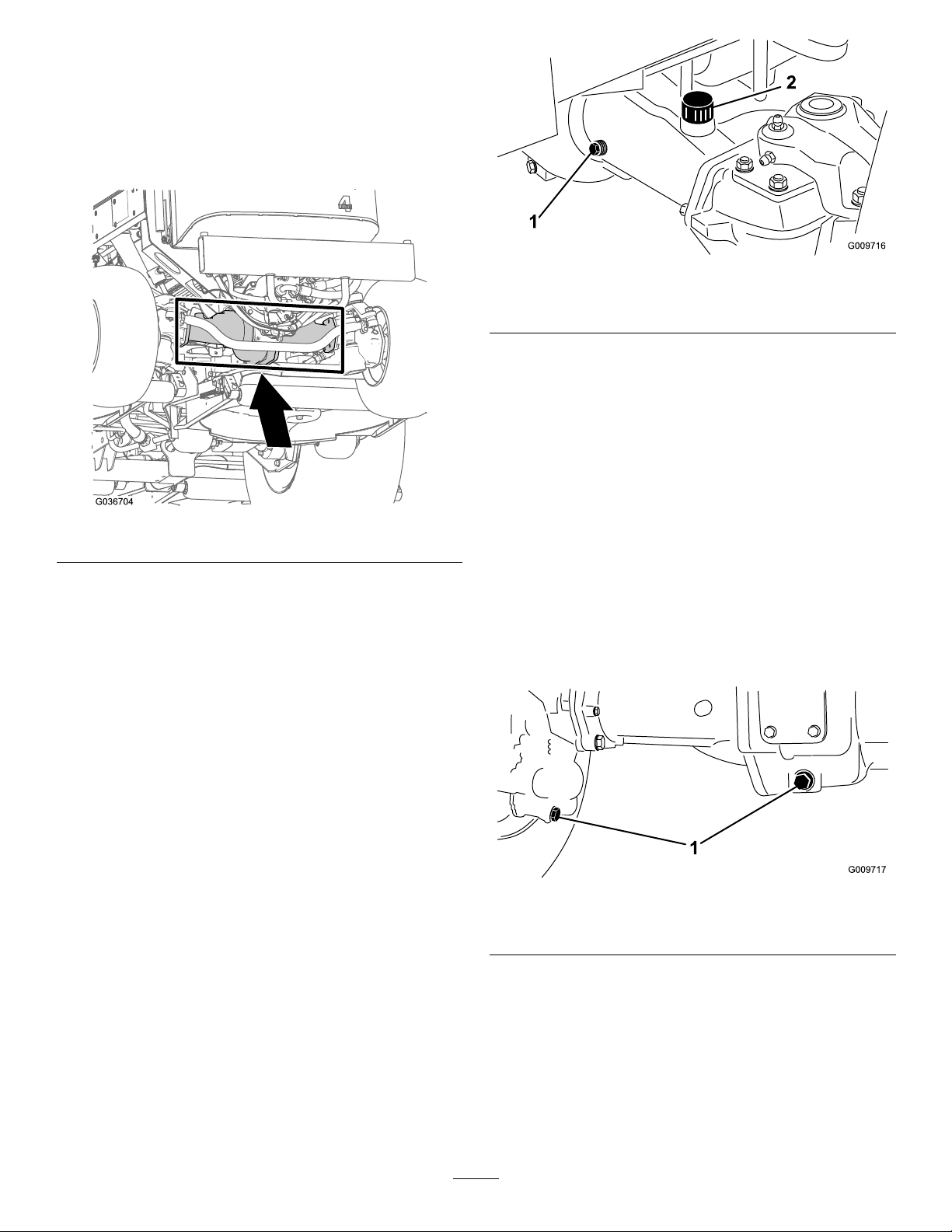
CheckingtheRearAxleand GearboxforLeaks
ServiceInterval:Beforeeachuseordaily
Visuallyinspecttherearaxleandrear-axlegearbox
forleaks.
g009716
Figure106
Figure105
CheckingtheRear-Axle Lubricant
ServiceInterval:Every400hours
TherearaxleislledwithSAE85W-140gearlube.
Thecapacityis2.4L(80oz).Visuallyinspectfor
leaksdaily.
1.Checkplug
2.Fillplug
ChangingtheRear-Axle Lubricant
ServiceInterval:Aftertherst200hours
Every800hours
g036704
Lubricantspecication:high-qualitySAE85W-140
gearlubricant
Axlecapacity:2.4L(80oz)
1.Parkthemachineonalevelsurface,engagethe
parkingbrake,lowerthemowerdecks,shutoff
theengine,andremovethekey.
2.Cleantheareaaroundthe3drainplugs—1on
eachendand1inthecenter(Figure107).
1.Parkthemachineonalevelsurface,engagethe
parkingbrake,lowerthemowerdecks,shutoff
theengine,andremovethekey.
2.Removeacheckplugfrom1endoftheaxleand
ensurethatthelubricantisuptothebottomof
thehole(Figure106).
Note:Ifthelevelislow,removethellplugand
addenoughlubricanttobringtheleveluptothe
bottomofthecheck-plugholes.
g009717
Figure107
1.Drain-pluglocation
3.Removetheoil-levelcheckplugsandthe
main-axle-ventcaptoeasedrainingthegear
lubricant.
4.Removethedrainplugsandallowthegear
lubricanttodrainintothepans.
5.Installtheplugs.
6.Removeacheckplugandlltheaxlewith
approximately2.4L(80oz)of85W-140gear
68

lubeoruntilthelubricantisuptothebottomof
thehole.
7.Installthecheckplug.
Checkingthe Rear-Axle-Gearbox Lubricant
ServiceInterval:Every400hours
ThegearboxislledwithSAE85W-140gearlube.
Thecapacityis0.5L(16oz).Visuallyinspectfor
leaksdaily.
1.Parkthemachineonalevelsurface,engagethe
parkingbrake,lowerthemowerdecks,shutoff
theengine,andremovethekey.
2.Removethecheck/llplugfromtheleftsideof
thegearboxandensurethatlubricantisupto
thebottomofthehole(Figure108).
Note:Ifthelevelislow,addenoughlubricantto
bringtheleveluptothebottomofthehole.
CheckingtheRearWheel Toe-In
ServiceInterval:Every800hours/Yearly(whichever
comesrst)
1.Parkthemachineonalevelsurface,engagethe
parkingbrake,lowerthemowerdecks,shutoff
theengine,andremovethekey.
2.Measurethecenter-to-centerdistance(ataxle
height)atthefrontandrearofthesteeringtires
(Figure109).
Note:Thefrontmeasurementmustbe3mm
(1/8inch)lessthantherearmeasurement.
Figure108
1.Gearbox2.Check/llplug
g009169
Figure109
1.Frontofthemachine3.Centertocenterdistance
2.3mm(1/8inch)lessthan
therearmeasurement
3.Toadjust,removethecotterpinandnutfrom
eithertierodballjoint(Figure1 10).Removethe
tie-rodballjointfromtheaxle-casesupport.
g011488
g009718
Figure110
1.Tie-rodclamp2.Tie-rodballjoint
4.Loosentheclampsatbothendsofthetierods
(Figure110).
5.Rotatethedetachedballjointinwardoroutward
1completerevolutionandtightentheclampat
thelooseendofthetierod.
6.Rotatetheentiretie-rodassemblythesame
direction(inwardoroutward)1complete
69

revolutionandtightentheclampatthe
connectedendofthetierod.
CoolingSystem
7.Installtheballjointintheaxle-casesupport,
tightenthenutnger-tight,andmeasurethe
toe-in.
8.Repeatprocedureifnecessary .
9.Tightenthenutandinstallanewcotterpinwhen
theadjustmentiscorrect.
Maintenance
CoolingSystemSafety
•Swallowingenginecoolantcancausepoisoning;
keepoutofreachfromchildrenandpets.
•Dischargeofhot,pressurizedcoolantortouching
ahotradiatorandsurroundingpartscancause
severeburns.
–Alwaysallowtheenginetocoolatleast15
minutesbeforeremovingtheradiatorcap.
–Usearagwhenopeningtheradiatorcap,and
openthecapslowlytoallowsteamtoescape.
CheckingtheCooling System
ServiceInterval:Beforeeachuseordaily
Coolantspecication:50/50mixtureofwaterand
ethyleneglycolantifreeze
Coolingsystemcapacity:8.5L(9USqt).
1.Parkthemachineonalevelsurface,engagethe
parkingbrake,lowerthemowerdecks,shutoff
theengine,andremovethekey.
2.Carefullyremovetheradiatorcap.
CAUTION
Iftheenginehasbeenrunning,the
pressurized,hotcoolantcanescapeand
causeburns.
•Donotopentheradiatorcapwhenthe
engineisrunning.
•Usearagwhenopeningtheradiator
cap,andopenthecapslowlytoallow
steamtoescape.
70

Figure111
1.Expansiontank
3.Checkthecoolantlevelintheradiator.The
radiatorshouldbelledtothetopoftheller
neckandtheexpansiontanklledtotheFULL
mark(Figure111).
4.Ifthecoolantislow,adda50/50mixtureofwater
andethyleneglycolanti-freeze.Donotuse
wateronlyoralcohol/methanolbasedcoolants.
5.Installtheradiatorcapandexpansion-tankcap.
3.Cleanthescreenthoroughlyofalldebris.
g198662
g009702
1.Rear-screenlatch
Figure112
4.Thoroughlycleanbothsidesoftheoilcoolerand
theradiatorwithcompressedair(Figure1 13).
Note:Startfromthefrontandblowthedebris
outtowardtheback.Thencleanfromthe
backsideandblowtowardthefront.Repeat
procedureseveraltimesuntilyouremoveall
chaffanddebris.
CleaningtheCooling System
ServiceInterval:Beforeeachuseordaily—Remove
debrisfromtheenginearea,oil
cooler,andradiator(cleanthem
morefrequentlyindirtyconditions).
Thismachineisequippedwithahydraulicallydriven
fandrivesystemthatautomatically(ormanually)
reversestoreduceoilcooler/radiatorandscreen
debrisbuildup.Whilethisfeaturecanhelpreduce
thetimerequiredtocleanoilcooler/radiator,itdoes
noteliminatetheneedforroutinecleaning.Periodic
cleaningandinspectionoftheradiator/coolerisstill
required.
1.Parkthemachineonalevelsurface,engagethe
parkingbrake,lowerthemowerdecks,shutoff
theengine,andremovethekey.
2.Unlatchandswingopentherearscreen(Figure
112).
Note:T oremovethescreen,liftitoffthehinge
pins.
g020509
Figure113
1.Oilcooler/radiator
Important:Cleaningtheoilcooler/radiator
withwaterpromotesprematurecorrosion
71
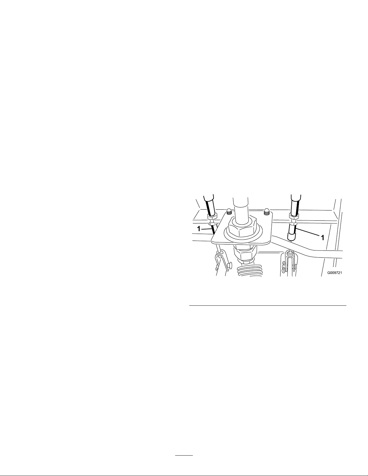
damagetocomponentsandcompacts
debris.
5.Closetherearscreenandsecureitwiththe
latch.
BrakeMaintenance
AdjustingtheService Brakes
Adjusttheservicebrakeswhenthereismorethan
25mm(1inch)offreetravelofthebrakepedal,or
whenthebrakesdonotworkeffectively.Freetravelis
thedistancethebrakepedalmovesbeforeyoufeel
brakingresistance.
1.Parkthemachineonalevelsurface,engagethe
parkingbrake,lowerthemowerdecks,shutoff
theengine,andremovethekey.
2.Releasethelockinglatchfromthebrakepedals
sothatbothpedalsworkindependentlyofeach
other.
3.Toreducefreetravelofthebrakepedals,tighten
thebrakesasfollows:
A.Loosenthefrontnutonthethreadedendof
thebrakecable(Figure114).
Figure114
1.Brakecable
B.Tightentherearnuttomovethecable
rearwarduntilthebrakepedalshave13to
25mm(1/2to1inch)offreetravel.
C.Tightenthefrontnutsafterthebrakesare
adjustedcorrectly.
g009721
72
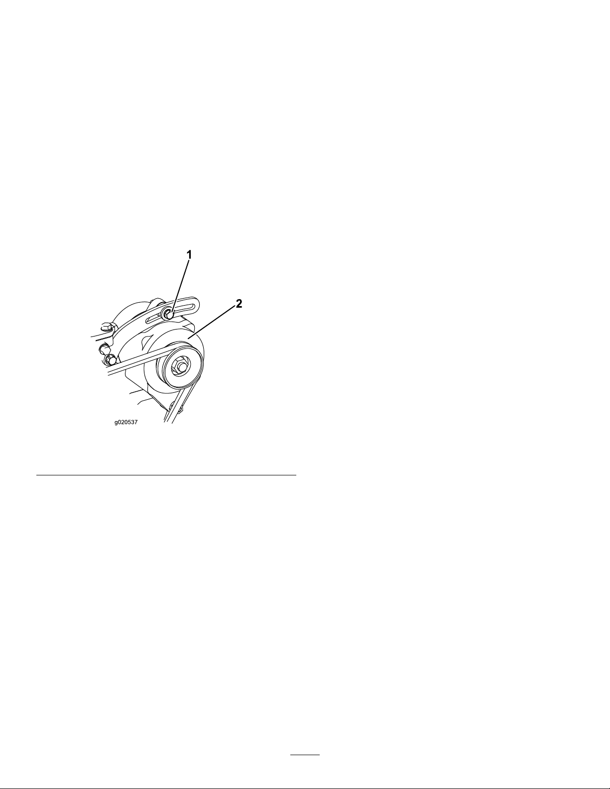
BeltMaintenance
ServicingtheAlternator
HydraulicSystem
Maintenance
Belt
ServiceInterval:Every100hours
Propertensionofthebeltallows10mm(3/8inch)of
deectionwhenaforceof4.5kg(10lb)isappliedon
thebeltmidwaybetweenthepulleys.
Ifthedeectionisnot10mm(3/8inch),loosenthe
alternator-mountingbolts(Figure115).
Note:Increaseordecreasethealternator-belt
tensionandtightenthebolts.Checkthedeectionof
thebeltagaintoensurethatthetensioniscorrect.
HydraulicSystemSafety
•Ensurethatallhydraulic-uidhosesandlinesare
ingoodconditionandallhydraulicconnections
andttingsaretightbeforeapplyingpressureto
thehydraulicsystem.
•Keepyourbodyandhandsawayfrompinhole
leaksornozzlesthatejecthigh-pressurehydraulic
uid.
•Usecardboardorpapertondhydraulicleaks.
•Safelyrelieveallpressureinthehydraulicsystem
beforeperforminganyworkonthehydraulic
system.
•Seekimmediatemedicalattentionifuidisinjected
intoskin.Injecteduidmustbesurgicallyremoved
withinafewhoursbyadoctor.
Checkingthe Hydraulic-FluidLevel
ServiceInterval:Beforeeachuseordaily
Figure115
1.Mountingbolt2.Alternator
Thereservoirislledatthefactorywithapproximately
28.4L(7.50USgallons)ofhigh-qualityhydraulicuid.
g020537
Checkthelevelofthehydraulicuidbeforetheengine
isrststartedanddailythereafter.Therecommended
replacementuidisasfollows:
ToroPremiumAllSeasonHydraulicFluid
(Availablein19L(5USgallon)pailsor208L(55
USgallon)drums.SeethePartsCatalogoryour
authorizedT orodistributorforpartnumbers).
Alternativeuids:IftheT orouidisnotavailable,
otherconventional,petroleum-baseduidsmaybe
used,providedtheymeetallthefollowingmaterial
propertiesandindustryspecications.Checkwith
youroilsuppliertoseewhethertheoilmeetsthese
specications.
Note:T orodoesnotassumeresponsibilityfor
damagecausedbyimpropersubstitutions,souse
onlyproductsfromreputablemanufacturerswhowill
standbehindtheirrecommendation.
73

HighViscosityIndex/LowPourPoint
Anti-WearHydraulicFluid,ISOVG46
MaterialProperties:
Viscosity,ASTMD445cSt@40°C(104°F)
ViscosityIndexASTM
D2270
PourPoint,ASTMD97-37°Cto-45°C(-34°Fto
IndustrySpecications:VickersI-286-S(Quality
44to50
cSt@100°C(212°F)
7.9to9.1
140to160
-49°F)
Level),VickersM-2950-S
(QualityLevel),Denison
HF-0
Important:TheISOVG46Multigradeuidhas
beenfoundtoofferoptimalperformanceinawide
rangeoftemperatureconditions.Foroperation
inconsistentlyhighambienttemperatures,65°F
(18°C)to120°F(49°C),ISOVG68hydraulicuid
mayofferimprovedperformance.
PremiumBiodegradableHydraulicFluid-Mobil
EALEnviroSyn46H
Important:MobilEALEnviroSyn46Histheonly
syntheticbiodegradableuidapprovedbyToro.
Thisuidiscompatiblewiththeelastomersused
inTorohydraulicsystemsandissuitablefora
wide-rangeoftemperatureconditions.Thisuidis
compatiblewithconventionalmineraloils,butfor
maximumbiodegradabilityandperformancethe
hydraulicsystemshouldbethoroughlyushed
ofconventionaluid.Theuidisavailablein19
L(5USgallon)containersor208L(55USgallon)
drumsfromyourMobilDistributor.
g198718
Important:Manyhydraulicuidsarealmost
colorless,makingitdifculttospotleaks.A
reddyeadditiveforthehydraulicsystemuid
isavailablein20ml(0.67oz)bottles.Abottle
issufcientfor15to22L(4to6USgallons)of
hydraulicuid.OrderPartNo.44-2500fromyour
authorizedTorodistributor.
1.Parkthemachineonalevelsurface,engagethe
parkingbrake,lowerthecuttingunits,shutoff
theengine,andremovethekey.
2.Checkthehydraulic-uidlevel(Figure116).
g031863
Figure116
74

ChangingtheHydraulic
ReplacingtheHydraulic
Fluid
ServiceInterval:Every800hours
Iftheuidbecomescontaminated,contactyourT oro
Distributorbecausethesystemmustbeushed.
Contaminateduidlooksmilkyorblackwhen
comparedtocleanoil.
1.Parkthemachineonalevelsurface,engagethe
parkingbrake,lowerthemowerdecks,shutoff
theengine,andremovethekey.
2.Raisethehood.
3.Disconnectthecasereturnlinefromthebottom
ofthereservoirandletthehydraulicuidow
intoalargedrainpan.
4.Installthehosewhenthehydraulicuidstops
draining.
5.Fillthereservoirwithhydraulicuid;referto
CheckingtheHydraulic-FluidLevel(page73).
Important:Useonlythehydraulicuids
specied.Otheruidscouldcausesystem
damage.
Filters
ServiceInterval:Aftertherst200hours
Every800hours
UseTororeplacementltersPartNo.94-2621for
therear(mowerdecks)ofthemachineandPartNo.
75-1310forthefront(charge)ofthemachine.
Important:Useofanyotherltermayvoidthe
warrantyonsomecomponents.
1.Tilttheoperator’sseattoaccessthemower
pressurelter;refertoAccessingtheHydraulic
LiftCompartment(page55)
6.Installthereservoircap.
7.TurnthekeyinthekeyswitchtotheONposition
tostarttheengine.Useallthehydrauliccontrols
todistributehydraulicuidthroughoutthe
system,andcheckforleaks.
8.TurnthekeyinthekeyswitchtotheOFF
position.
9.Checktheuidlevelandaddenoughtoraise
leveltheleveltotheFULLmarkonthedipstick.
Donotoverll.
g201858
Figure117
2.Replacethechargehydrauliclteratthe
hydraulicliftcompartmentasshowninFigure
118.
75

CuttingUnitMaintenance
RemovingtheCuttingUnits
1.Parkthemachineonalevelsurface,engagethe
parkingbrake,lowerthecuttingunits,shutoff
theengine,andremovethekey.
g036709
2.Disconnectandremovethehydraulicmotor
fromthecuttingunit(Figure119).Coverthetop
ofthespindletopreventcontamination.
g011351
Figure119
1.Motor-mountingscrews
3.Removethelynchpin(forGroundsmaster4500
machines)orretainingnut(forGroundsmaster
4700machines)securingthecuttingunit-carrier
frametothelift-armpivotpin(Figure120).
Figure118
3.Lowerandsecuretheoperator’sseat.
4.Replacethereturnlterattherightsideofthe
machine(Figure118).
5.Starttheengineandletitrunforabout2minutes
topurgeairfromthesystem.Shutofftheengine
andcheckforleaks.
CheckingtheHydraulic LinesandHoses
ServiceInterval:Beforeeachuseordaily
Inspectthehydrauliclinesandhosesdailyfor
leaks,kinkedlines,loosemountingsupports,wear,
loosettings,weatherdeterioration,andchemical
deterioration.Makeallnecessaryrepairsbefore
operatingthemachine.
g031621
g011352
Figure120
1.Lynchpin
4.Rollthecuttingunitawayfromthemachine.
2.Lift-armpivotpin
76

InstallingtheCuttingUnits
1.Movethecuttingunitintopositioninfrontofthe
machine.
2.Slidethecuttingunit-carrierframeontothe
lift-arm-pivotpin(Figure120).Securethe
cuttingunittothepinwiththelynchpin(for
Groundsmaster4500machines)orretainingnut
(forGroundsmaster4700machines).
3.Installthehydraulicmotortothecuttingunit
(Figure119).MakesurethattheO-ringisin
positionandnotdamaged.
4.Greasethespindle.
ServicingtheFrontRoller
Inspectthefrontrollerforwear,excesswobble,or
binding.Serviceorreplacetherollerorcomponentsif
anyoftheseconditionsexist.
DisassemblingtheFrontRoller
1.Removetheroller-mountingbolt(Figure121).
AssemblingtheFrontRoller
1.Presstherstbearingintotherollerhousing
(Figure121).Pressontheouterraceonlyor
equallyontheinnerandouterrace.
2.Insertthespacer(Figure121).
3.Pressthesecondbearingintotherollerhousing
(Figure121).Pressingequallyontheinner
andouterraceuntiltheinnerracecontactsthe
spacer.
4.Installtherollerassemblyintothecutting-unit
frame.
5.Verifythatthereisnomorethana1.5mm(0.060
inch)gapbetweenrollerassemblyandtheroller
mountbracketsofthecutting-unitframe.Ifthere
isagapover1.5mm(0.060inch),installenough
5/8-inchdiameterwasherstotakeuptheslop.
Important:Securingtherollerassembly
withagaplargerthan1.5mm(0.060inch)
createsasideloadonthebearingandcan
leadtoprematurebearingfailure
6.Torquethemountingboltto108N∙m(80ft-lb).
2.Insertapunchthroughtheendoftheroller
housinganddrivetheoppositebearingoutby
alternatingtapstotheoppositesideofinner
bearingrace.Thereshouldbea1.5mm(0.060
inch)lipofinnerraceexposed.
Figure121
1.Frontroller3.Bearing
2.Mountingbolt4.Bearingspacer
3.Pushthesecondbearingoutinpress.
g011356
4.Inspecttherollerhousing,bearings,andbearing
spacerfordamage(Figure121).Replaceany
damagedcomponentsandassemblethem.
77

BladeMaintenance
5.Rotatethemarkedendofthebladetothe3and
9o’clockpositions(Figure122)andmeasure
theheights.
BladeSafety
Awornordamagedbladecanbreak,andapiece
ofthebladecouldbethrownatyouorbystanders,
resultinginseriouspersonalinjuryordeath.
•Inspectthebladeperiodicallyforwearordamage.
•Usecarewhencheckingtheblades.Wrapthe
bladesorweargloves,andusecautionwhen
servicingtheblades.Onlyreplaceorsharpenthe
blades;neverstraightenorweldthem.
•Onmulti-bladedmachines,takecareasrotating1
bladecancauseotherbladestorotate.
ServicingtheBladePlane
Thecuttingunitcomesfromthefactorypresetat5
cm(2inches)heightofcutandbladerakeof7.9mm
(0.310inch).Theleftandrightheightsarealsopreset
towithin±0.7mm(0.030inch)oftheother.
Thecuttingunitisdesignedtowithstandblade
impactswithoutdeformationofthechamber.Ifthe
bladestrikesasolidobject,inspectthebladefor
damageandthebladeplaneforaccuracy.
6.Comparethe12o’clockmeasuredheighttothe
height-of-cutsetting.Itshouldbewithin0.7mm
(0.030inch).The3and9o’clockheightsshould
be1.6to6.0mm(0.060to0.240inch)higher
thanthe12o’clocksettingandwithin2.2mm
(0.090inch)ofeachother.
Ifanyofthesemeasurementsarenotwithin
specication,proceedtoAdjustingtheBladePlane
(page78).
AdjustingtheBladePlane
Startwiththefrontadjustment(change1bracketata
time).
1.Removetheheight-of-cutbracket,(front,left,or
right)fromthecutting-unitframe(Figure123).
2.Adjust1.5mm(0.060inch)shimsand/or0.7
mm(0.030inch)shimsbetweenthecutting-unit
frameandbrackettoachievethedesiredheight
setting(Figure123).
InspectingtheBladePlane
1.Removethehydraulicmotorfromthecuttingunit
andremovethecuttingunitfromthemachine.
2.Useahoist(orminimumof2people)andplace
thecuttingunitonaattable.
3.Mark1endofthebladewithapaintpenor
marker.Usethisendofthebladetocheckall
heights.
4.Positionthecuttingedgeofthemarkedendof
thebladeat12o’clock(straightaheadinthe
directionofmowing)(Figure122)andmeasure
heightfromtabletocuttingedgeofblade.
g011354
Figure123
1.Height-of-cutbracket2.Shims
3.Installtheheight-of-cutbrackettothecutting-unit
framewiththeremainingshimsassembled
belowtheheight-of-cutbracket.
4.Securethesocket-headbolt/spacerandange
nut.
Note:Socket-headbolt/spacerareheld
togetherwiththread-lockingadhesivetoprevent
thespacerfromfallinginsidethecutting-unit
frame.
Figure122
g011353
5.Verifythe12o’clockheightandadjustifneeded.
6.Determineifonly1orboth(rightandleft)
height-of-cutbracketsneedtobeadjusted.
78

Note:Ifthe3or9o’clocksideis1.6to6.0mm
(0.060to0.240inch)higherthanthenewfront
heightthennoadjustmentisneededforthat
side.Adjusttheothersidetowithin±2.2mm
(0.090inch)ofthecorrectside.
7.Adjusttherightand/orleftheight-of-cutbrackets
byrepeatingsteps1through4.
8.Securethecarriageboltsandangenuts.
9.Verifythe12,3,and9o’clockheights.
RemovingandInstalling theCutting-UnitBlade(s)
InspectingandSharpening theCutting-UnitBlade(s)
Boththecuttingedgesandthesail,whichisthe
turned-upportionoppositeofthecuttingedge,
contributetoagoodqualityofcut.Thesaillifts
thegrassupstraight,therebyproducinganeven
cut.However,thesailgraduallywearsdownduring
operation,loweringthequalityofcuteventhoughthe
cuttingedgesaresharp.Thecuttingedgeoftheblade
mustbesharpsothatthegrassiscutratherthantorn.
Adullcuttingedgeleavesthetipsofthegrassbrown
andshredded.Sharpenthecuttingedgestocorrect
thiscondition.
Replacethebladeifithitsasolidobject,isout
ofbalance,orisbent.AlwaysusegenuineT oro
replacementbladestoensuresafetyandoptimum
performance.
1.Parkthemachineonalevelsurface,raisethe
cuttingunittothehighestposition,engagethe
parkingbrake,shutofftheengine,andremove
thekey.
Note:Blockthecuttingunittopreventitfrom
accidentallyfalling.
2.Grasptheendofthebladeusingaragor
thickly-paddedglove.
3.Removethebladebolt,anti-scalpcup,and
bladefromthespindleshaft(Figure124).
1.Parkthemachineonalevelsurface,raisethe
cuttingunits,engagetheparkingbrake,putthe
tractionpedalinNEUTRAL,putthePTOlever
intheOFFposition,shutofftheengine,and
removethekey.
2.Examinethecuttingendsofthebladecarefully,
especiallywheretheatandcurvedpartsofthe
blademeet(Figure125).
Note:Becausesandandabrasivematerial
canwearawaythemetalthatconnectstheat
andcurvedpartsoftheblade,checktheblade
beforeusingthemachine.Ifyounoticewear,
(Figure125),replacetheblade.
Figure124
1.Bladebolt2.Anti-scalpcup
4.Installtheblade,anti-scalpcup,andbladebolt
andtightenthebladeboltto115to149N∙m(85
to110ft-lb).
Important:Thecurvedpartoftheblade
mustbepointingtowardtheinsideofthe
cuttingunittoensurepropercutting.
Note:Afterstrikingaforeignobject,torqueall
spindle-pulleynutsto115to149N∙m(85to110
ft-lb).
g011355
79

Note:Removethebladesandsharpenthem
onagrinder.Aftersharpeningthecuttingedges,
installthebladewiththeanti-scalpcupand
bladebolt;refertoRemovingandInstallingthe
Cutting-UnitBlade(s)(page79).
Figure125
1.Cuttingedge3.Wear/slotforming
2.Curvedarea4.Crack
3.Examinethecuttingedgesofallthebladesand
sharpenthecuttingedgesiftheyaredullor
nicked(Figure126).
Note:Sharpenonlythetopofthecutting
edgeandmaintaintheoriginalcuttingangle
toensuresharpness(Figure126).Theblade
remainsbalancedifthesameamountofmetal
isremovedfrombothcuttingedges.
Figure126
g004653
g000276
1.Sharpenattheoriginalangle.
80

Storage
PreparingforSeasonal
10.Checktheanti-freezeprotectionandadda
50/50solutionofwaterandethyleneglycol
anti-freezeasneededfortheexpectedminimum
temperatureinyourarea.
Storage
TractionUnit
1.Thoroughlycleanthetractionunit,mowerdecks,
andtheengine.
2.Checkthetirepressure;refertoCheckingthe
TirePressure(page26).
3.Checkallfastenersforlooseness;tightenas
necessary.
4.Greaseoroilallgreasettingsandpivotpoints.
Wipeupanyexcesslubricant.
5.Lightlysandandusetouch-uppaintonpainted
areasthatarescratched,chipped,orrusted.
Repairanydentsinthemetalbody.
6.Servicethebatteryandcablesasfollows:
A.Removethebatteryterminalsfromthe
batteryposts.
B.Cleanthebattery,terminals,andpostswith
awirebrushandbakingsodasolution.
C.Coatthecableterminalsandbatteryposts
withGrafo112Xskin-overgrease(T oroPart
No.505-47)orpetroleumjellytoprevent
corrosion.
MowerDeck
Ifthemowerdecksareseparatedfromthetraction
unitforanylengthoftime,installaspindlepluginthe
topofthespindlestoprotectthespindlesfromdust
andwater.
g036712
Figure127
1.Spindleplug2.Spindlesprocket
D.Slowlyrechargethebatteryevery60days
for24hourstopreventleadsulfationofthe
battery.
7.Engagethetransportlatches(Groundsmaster
4700-Dmachinesonly).
Engine
1.Draintheengineoilfromtheoilpanandinstall
thedrainplug.
2.Removeanddiscardtheoillter.Installanew
oillter.
3.Filltheoilpanwithmotoroil.
4.Starttheengineandrunitatidlespeedfor
approximately2minutes.
5.Shutofftheengine.
6.Flushthefueltankwithfresh,cleandieselfuel.
7.Secureallfuelsystemttings.
8.Thoroughlycleanandservicetheair-cleaner
assembly.
9.Sealtheair-cleanerinletandtheexhaustoutlet
withweatherprooftape.
81

Notes:

EuropeanPrivacyNotice
TheInformationToroCollects
ToroWarrantyCompany(Toro)respectsyourprivacy.Inordertoprocessyourwarrantyclaimandcontactyouintheeventofaproductrecall,weaskyou
tosharecertainpersonalinformationwithus,eitherdirectlyorthroughyourlocalTorocompanyordealer.
TheT orowarrantysystemishostedonserverslocatedwithintheUnitedStateswhereprivacylawmaynotprovidethesameprotectionasapplies
inyourcountry.
BYSHARINGYOURPERSONALINFORMATIONWITHUS,YOUARECONSENTINGTOTHEPROCESSINGOFYOURPERSONALINFORMATION
ASDESCRIBEDINTHISPRIV ACYNOTICE.
TheWayT oroUsesInformation
Toromayuseyourpersonalinformationtoprocesswarrantyclaims,tocontactyouintheeventofaproductrecallandforanyotherpurposewhichwetell
youabout.ToromayshareyourinformationwithToro'safliates,dealersorotherbusinesspartnersinconnectionwithanyoftheseactivities.Wewillnot
sellyourpersonalinformationtoanyothercompany.Wereservetherighttodisclosepersonalinformationinordertocomplywithapplicablelawsand
withrequestsbytheappropriateauthorities,tooperateoursystemsproperlyorforourownprotectionorthatofotherusers.
RetentionofyourPersonalInformation
Wewillkeepyourpersonalinformationaslongasweneeditforthepurposesforwhichitwasoriginallycollectedorforotherlegitimatepurposes
(suchasregulatorycompliance),orasrequiredbyapplicablelaw .
Toro'sCommitmenttoSecurityofYourPersonalInformation
Wetakereasonableprecautionsinordertoprotectthesecurityofyourpersonalinformation.Wealsotakestepstomaintaintheaccuracyandcurrent
statusofpersonalinformation.
AccessandCorrectionofyourPersonalInformation
Ifyouwouldliketorevieworcorrectyourpersonalinformation,pleasecontactusbyemailatlegal@toro.com.
AustralianConsumerLaw
AustraliancustomerswillnddetailsrelatingtotheAustralianConsumerLaweitherinsidetheboxoratyourlocalT oroDealer.
374-0282RevC

TheToroWarranty
ATwo-YearLimitedWarranty
ConditionsandProductsCovered
TheToroCompanyanditsafliate,T oroWarrantyCompany,pursuant
toanagreementbetweenthem,jointlywarrantyourT oroCommercial
product(“Product”)tobefreefromdefectsinmaterialsorworkmanship
fortwoyearsor1500operationalhours*,whicheveroccursrst.This
warrantyisapplicabletoallproductswiththeexceptionofAerators
(refertoseparatewarrantystatementsfortheseproducts).Wherea
warrantableconditionexists,wewillrepairtheProductatnocosttoyou
includingdiagnostics,labor,parts,andtransportation.Thiswarranty
beginsonthedatetheProductisdeliveredtotheoriginalretailpurchaser.
*Productequippedwithanhourmeter.
InstructionsforObtainingWarrantyService
YouareresponsiblefornotifyingtheCommercialProductsDistributoror
AuthorizedCommercialProductsDealerfromwhomyoupurchasedthe
Productassoonasyoubelieveawarrantableconditionexists.Ifyouneed
helplocatingaCommercialProductsDistributororAuthorizedDealer,or
ifyouhavequestionsregardingyourwarrantyrightsorresponsibilities,
youmaycontactusat:
ToroCommercialProductsServiceDepartment
ToroWarrantyCompany
811 1LyndaleAvenueSouth
Bloomington,MN55420-1196
952–888–8801or800–952–2740
E-mail:commercial.warranty@toro.com
OwnerResponsibilities
AstheProductowner,youareresponsibleforrequiredmaintenanceand
adjustmentsstatedinyourOperator'sManual.Failuretoperformrequired
maintenanceandadjustmentscanbegroundsfordisallowingawarranty
claim.
ItemsandConditionsNotCovered
Notallproductfailuresormalfunctionsthatoccurduringthewarranty
periodaredefectsinmaterialsorworkmanship.Thiswarrantydoesnot
coverthefollowing:
•Productfailureswhichresultfromtheuseofnon-Tororeplacement
parts,orfrominstallationanduseofadd-on,ormodiednon-Toro
brandedaccessoriesandproducts.Aseparatewarrantymaybe
providedbythemanufactureroftheseitems.
•Productfailureswhichresultfromfailuretoperformrecommended
maintenanceand/oradjustments.Failuretoproperlymaintainyour
ToroproductpertheRecommendedMaintenancelistedinthe
Operator’sManualcanresultinclaimsforwarrantybeingdenied.
•ProductfailureswhichresultfromoperatingtheProductinanabusive,
negligent,orrecklessmanner.
•Partssubjecttoconsumptionthroughuseunlessfoundtobedefective.
Examplesofpartswhichareconsumed,orusedup,duringnormal
Productoperationinclude,butarenotlimitedto,brakepadsand
linings,clutchlinings,blades,reels,rollersandbearings(sealedor
greasable),bedknives,sparkplugs,castorwheelsandbearings,tires,
lters,belts,andcertainsprayercomponentssuchasdiaphragms,
nozzles,andcheckvalves,etc.
•Failurescausedbyoutsideinuence.Conditionsconsideredtobe
outsideinuenceinclude,butarenotlimitedto,weather,storage
practices,contamination,useofunapprovedfuels,coolants,lubricants,
additives,fertilizers,water,orchemicals,etc.
•Failureorperformanceissuesduetotheuseoffuels(e.g.gasoline,
diesel,orbiodiesel)thatdonotconformtotheirrespectiveindustry
standards.
•Normalnoise,vibration,wearandtear,anddeterioration.
•Normal“wearandtear”includes,butisnotlimitedto,damagetoseats
duetowearorabrasion,wornpaintedsurfaces,scratcheddecalsor
windows,etc.
Parts
Partsscheduledforreplacementasrequiredmaintenancearewarranted
fortheperiodoftimeuptothescheduledreplacementtimeforthatpart.
Partsreplacedunderthiswarrantyarecoveredforthedurationofthe
originalproductwarrantyandbecomethepropertyofT oro.T orowillmake
thenaldecisionwhethertorepairanyexistingpartorassemblyorreplace
it.T oromayuseremanufacturedpartsforwarrantyrepairs.
DeepCycleandLithium-IonBatteryWarranty:
DeepcycleandLithium-Ionbatterieshaveaspeciedtotalnumberof
kilowatt-hourstheycandeliverduringtheirlifetime.Operating,recharging,
andmaintenancetechniquescanextendorreducetotalbatterylife.Asthe
batteriesinthisproductareconsumed,theamountofusefulworkbetween
chargingintervalswillslowlydecreaseuntilthebatteryiscompletelyworn
out.Replacementofwornoutbatteries,duetonormalconsumption,
istheresponsibilityoftheproductowner.Batteryreplacementmaybe
requiredduringthenormalproductwarrantyperiodatowner’sexpense.
Note:(Lithium-Ionbatteryonly):ALithium-Ionbatteryhasapartonly
proratedwarrantybeginningyear3throughyear5basedonthetime
inserviceandkilowatthoursused.RefertotheOperator'sManualfor
additionalinformation.
MaintenanceisatOwner’sExpense
Enginetune-up,lubrication,cleaningandpolishing,replacementoflters,
coolant,andcompletingrecommendedmaintenancearesomeofthe
normalservicesT oroproductsrequirethatareattheowner’sexpense.
GeneralConditions
RepairbyanAuthorizedToroDistributororDealerisyoursoleremedy
underthiswarranty.
NeitherTheToroCompanynorToroWarrantyCompanyisliablefor
indirect,incidentalorconsequentialdamagesinconnectionwiththe
useoftheToroProductscoveredbythiswarranty,includingany
costorexpenseofprovidingsubstituteequipmentorserviceduring
reasonableperiodsofmalfunctionornon-usependingcompletion
ofrepairsunderthiswarranty.ExceptfortheEmissionswarranty
referencedbelow,ifapplicable,thereisnootherexpresswarranty.All
impliedwarrantiesofmerchantabilityandtnessforusearelimitedto
thedurationofthisexpresswarranty.
Somestatesdonotallowexclusionsofincidentalorconsequential
damages,orlimitationsonhowlonganimpliedwarrantylasts,sotheabove
exclusionsandlimitationsmaynotapplytoyou.Thiswarrantygivesyou
speciclegalrights,andyoumayalsohaveotherrightswhichvaryfrom
statetostate.
Noteregardingenginewarranty:
TheEmissionsControlSystemonyourProductmaybecoveredby
aseparatewarrantymeetingrequirementsestablishedbytheU.S.
EnvironmentalProtectionAgency(EPA)and/ortheCaliforniaAirResources
Board(CARB).Thehourlimitationssetforthabovedonotapplytothe
EmissionsControlSystemWarranty.RefertotheEngineEmissionControl
WarrantyStatementsuppliedwithyourproductorcontainedintheengine
manufacturer’sdocumentationfordetails
CountriesOtherthantheUnitedStatesorCanada
CustomerswhohavepurchasedT oroproductsexportedfromtheUnitedStatesorCanadashouldcontacttheirT oroDistributor(Dealer)toobtain
guaranteepoliciesforyourcountry ,province,orstate.IfforanyreasonyouaredissatisedwithyourDistributor'sserviceorhavedifcultyobtaining
guaranteeinformation,contacttheT oroimporter.
374-0253RevD
 Loading...