

Page 1
FormNo.3358-752Rev D
Groundsmaster
®
4500-Dor
4700-DTractionUnit
ModelNo.30856—SerialNo.280000001andUp
ModelNo.30856TE—SerialNo.280000001andUp
ModelNo.30868—SerialNo.280000001andUp
ModelNo.30868TE—SerialNo.280000001andUp
ToregisteryourproductordownloadanOperator'sManualorPartsCatalogatnocharge,gotowww.T oro.com.OriginalInstructions(EN)
Page 2
Warning
CALIFORNIA
Proposition65Warning
Dieselengineexhaustandsomeofits
constituentsareknowntotheStateof
Californiatocausecancer,birthdefects,
andotherreproductiveharm.
Becauseinsomeareastherearelocal,state,orfederal
regulationsrequiringthatasparkarresterbeusedonthe
engineofthismachine,asparkarresterisincorporated
withthemuferassembly.
GenuineTorosparkarrestersareapprovedbytheUSDA
ForestryService.
Figure1
Important:Thisengineisequippedwithaspark
arrestermufer.ItisaviolationofCaliforniaPublic
ResourceCodeSection4442touseoroperate
theengineonanyforest-covered,brush-covered,
orgrass-coveredlandwithoutasparkarrester
mufermaintainedinworkingorder,ortheengine
constricted,equipped,andmaintainedforthe
preventionofre.Otherstatesorfederalareasmay
havesimilarlaws.
ThissparkignitionsystemcomplieswithCanadian
ICES-002.
Theenclosed
EngineOwner’sManual
issupplied
forinformationregardingtheUSEnvironmental
ProtectionAgency(EPA)andtheCalifornia
EmissionControlRegulationofemissionsystems,
maintenance,andwarranty.Replacementsmaybe
orderedthroughtheenginemanufacturer.
Introduction
Readthisinformationcarefullytolearnhowtooperate
andmaintainyourproductproperlyandtoavoidinjury
andproductdamage.Youareresponsibleforoperating
theproductproperlyandsafely.
ModelNo.
SerialNo.
Thismanualidentiespotentialhazardsandhas
safetymessagesidentiedbythesafetyalertsymbol
(Figure2),whichsignalsahazardthatmaycauseserious
injuryordeathifyoudonotfollowtherecommended
precautions.
Figure2
1.Safetyalertsymbol.
Thismanualusestwootherwordstohighlight
information.Importantcallsattentiontospecial
mechanicalinformationandNoteemphasizesgeneral
informationworthyofspecialattention.
YoumaycontactTorodirectlyatwww .Toro.comfor
productandaccessoryinformation,helpndinga
dealer,ortoregisteryourproduct.
Wheneveryouneedservice,genuineToroparts,or
additionalinformation,contactanAuthorizedService
DealerorToroCustomerServiceandhavethemodel
andserialnumbersofyourproductready.Figure1
identiesthelocationofthemodelandserialnumbers
ontheproduct.Writethenumbersinthespace
provided.
©2007—TheToro®Company
8111LyndaleAvenueSouth
Bloomington,MN55420
Contactusatwww.Toro.com.
2
PrintedintheUSA.
AllRightsReserved
Page 3

Contents
Introduction.................................................................2
Safety...........................................................................4
SafeOperatingPractices.......................................4
ToroRidingMowerSafety....................................6
SoundPressureLevelfora4500-D.......................7
SoundPressureLevelfora4700-D.......................7
SoundPowerLevel...............................................7
VibrationLevel.....................................................7
SafetyandInstructionalDecals.............................8
Setup..........................................................................13
1InstallingtheSeat,SeatBelt,andManual
Tube...............................................................13
2GreasingtheMachine......................................14
3CheckingFluidLevels......................................14
4ReadingtheManualsandViewingthe
TrainingMaterial............................................14
ProductOverview......................................................15
Controls.............................................................15
Specications.....................................................19
TractionUnitSpecications................................19
Attachments/Accessories...................................19
Operation...................................................................20
CheckingtheEngineOilLevel............................20
CheckingtheCoolingSystem..............................20
FillingtheFuelTank...........................................21
CheckingtheHydraulicFluidLevel.....................22
CheckingtheTirePressure.................................23
StartingandStoppingtheEngine........................23
CheckingtheInterlockSwitches.........................24
PushingorTowingtheMachine..........................25
JackingPoints.....................................................25
TieDowns.........................................................25
OperatingCharacteristics...................................25
StandardControlModule(SCM)........................26
OperatingTips...................................................28
Maintenance...............................................................29
RecommendedMaintenanceSchedule(s)................29
DailyMaintenanceChecklist...............................30
ServiceIntervalChart.........................................31
PremaintenanceProcedures....................................32
RemovingtheHood...........................................32
Lubrication.............................................................32
GreasingtheBearingsandBushings....................32
EngineMaintenance...............................................34
ServicingtheAirCleaner....................................34
ServicingtheEngineOilandFilter......................35
AdjustingtheThrottle........................................35
FuelSystemMaintenance.......................................36
FuelTank...........................................................36
FuelLinesandConnections................................36
ServicingtheWaterSeparator.............................36
FuelPick-upTubeScreen...................................36
BleedingtheFuelSystem....................................36
BleedingAirfromtheInjectors...........................37
ElectricalSystemMaintenance................................38
ChargingandConnectingtheBattery..................38
BatteryCare.......................................................39
Fuses..................................................................39
DriveSystemMaintenance.....................................40
CheckingtheTorqueoftheWheel
Nuts...............................................................40
CheckingthePlanetaryGearDrive
Oil..................................................................40
ChangingthePlanetaryGearDrive
Oil..................................................................40
CheckingtheRearAxleLubricant.......................41
ChangingtheRearAxleLubricant.......................41
AdjustingtheTractionDriveforNeutral.............42
CheckingtheRearWheelT oe-In.........................42
CoolingSystemMaintenance..................................43
ServicingtheEngineCoolingSystem..................43
BrakeMaintenance.................................................44
AdjustingtheServiceBrakes...............................44
BeltMaintenance....................................................45
ServicingtheAlternatorBelt...............................45
HydraulicSystemMaintenance...............................45
ChangingtheHydraulicFluid.............................45
ReplacingtheHydraulicFilters...........................45
CheckingtheHydraulicLinesandHoses.............46
HydraulicSystemTestPorts...............................46
AdjustingtheCounterbalance.............................47
Cleaning.................................................................48
ServicingtheSparkArrestorMufer...................48
Storage.......................................................................49
TractionUnit......................................................49
Engine...............................................................49
Schematics.................................................................50
3
Page 4

Safety
ThismachinemeetsorexceedsCENstandardEN
836:1997(whenappropriatedecalsapplied),andANSI
B71.4-2004specicationsineffectatthetimeof
productionwhenequippedwithrequiredweightsas
listedintheweightchart.
Improperuseormaintenancebytheoperatoror
ownercanresultininjury.Toreducethepotential
forinjury,complywiththesesafetyinstructions
andalwayspayattentiontothesafetyalertsymbol,
whichmeansCAUTION,WARNING,orDANGER"personalsafetyinstruction."Failuretocomplywiththe
instructionmayresultinpersonalinjuryordeath.
SafeOperatingPractices
ThefollowinginstructionsarefromtheCENstandard
EN836:1997,ISOstandard5395:1990,andANSI
B71.4-2004.
◊lackofawarenessoftheeffectofground
conditions,especiallyslopes;
•Theowner/usercanpreventandisresponsiblefor
accidentsorinjuriesoccurringtohimselforherself,
otherpeople,orproperty.
Preparation
•Whilemowing,alwayswearsubstantialfootwear,
longtrousers,hardhat,safetyglasses,andhearing
protection.Longhair,looseclothing,orjewelrymay
gettangledinmovingparts.Donotoperatethe
equipmentwhenbarefootorwearingopensandals.
•Thoroughlyinspecttheareawheretheequipment
istobeusedandremoveallobjectswhichmaybe
thrownbythemachine.
•Warning-Fuelishighlyammable.Takethe
followingprecautions:
–Storefuelincontainersspecicallydesignedfor
thispurpose.
Training
•Readtheoperator’smanualandothertraining
materialcarefully .Befamiliarwiththecontrols,
safetysigns,andtheproperuseoftheequipment.
•Iftheoperatorormechaniccannotreadthelanguage
ofthismanual,itistheowner’sresponsibilityto
explainthismaterialtothem.
•Neverallowchildrenorpeopleunfamiliarwiththese
instructionstouseorservicethemower.Local
regulationsmayrestricttheageoftheoperator.
•Nevermowwhilepeople,especiallychildren,orpets
arenearby .
•Keepinmindthattheoperatororuserisresponsible
foraccidentsorhazardsoccurringtootherpeopleor
theirproperty.
•Donotcarrypassengers.
•Alldriversandmechanicsshouldseekandobtain
professionalandpracticalinstruction.Theowneris
responsiblefortrainingtheusers.Suchinstruction
shouldemphasize:
–theneedforcareandconcentrationwhen
workingwithride-onmachines;
–controlofaride-onmachineslidingonaslope
willnotberegainedbytheapplicationofthe
brake.Themainreasonsforlossofcontrolare:
◊insufcientwheelgrip;
◊beingdriventoofast;
◊inadequatebraking;
◊thetypeofmachineisunsuitableforthetask;
–Refueloutdoorsonlyanddonotsmokewhile
refueling.
–Addfuelbeforestartingtheengine.Never
removethecapofthefueltankoraddfuelwhile
theengineisrunningorwhentheengineishot.
–Iffuelisspilled,donotattempttostartthe
enginebutmovethemachineawayfromthe
areaofspillageandavoidcreatinganysourceof
ignitionuntilfuelvaporshavedissipated.
–Replaceallfueltankandcontainercapssecurely.
•Replacefaultysilencers/mufers.
•Evaluatetheterraintodeterminewhataccessories
andattachmentsareneededtoproperlyand
safelyperformthejob.Onlyuseaccessoriesand
attachmentsapprovedbythemanufacturer.
•Checkthatoperator’spresencecontrols,safety
switchesandshieldsareattachedandfunctioning
properly.Donotoperateunlesstheyarefunctioning
properly.
Operation
•Donotoperatetheengineinaconnedspacewhere
dangerouscarbonmonoxidefumescancollect.
•Mowonlyindaylightoringoodarticiallight.
•Beforeattemptingtostarttheengine,disengageall
bladeattachmentclutches,shiftintoneutral,and
engagetheparkingbrake.
•Donotputhandsorfeetnearorunderrotatingparts.
Keepclearofthedischargeopeningatalltimes.
4
Page 5

•Rememberthereisnosuchthingasasafeslope.
Travelongrassslopesrequiresparticularcare.To
guardagainstoverturning:
–donotstoporstartsuddenlywhengoingupor
downhill;
–machinespeedsshouldbekeptlowonslopes
andduringtightturns;
–stayalertforhumpsandhollowsandother
hiddenhazards;
–nevermowacrossthefaceoftheslope,unless
themowerisdesignedforthispurpose.
–Usecounterweight(s)orwheelweightswhen
suggestedintheoperator’smanual.
•Stayalertforholesintheterrainandotherhidden
hazards.
•Watchoutfortrafcwhencrossingornearroadways.
•Stopthebladesfromrotatingbeforecrossing
surfacesotherthangrass.
•Whenusinganyattachments,neverdirectdischarge
ofmaterialtowardbystandersnorallowanyonenear
themachinewhileinoperation.
•Neveroperatethemachinewithdamagedguards,
shields,orwithoutsafetyprotectivedevicesinplace.
Besureallinterlocksareattached,adjustedproperly,
andfunctioningproperly.
•Donotchangetheenginegovernorsettingsor
overspeedtheengine.Operatingtheengineat
excessivespeedmayincreasethehazardofpersonal
injury.
•Beforeleavingtheoperator’ sposition:
–stoponlevelground;
–disengagethepowertake-offandlowerthe
attachments;
–changeintoneutralandsettheparkingbrake;
–stoptheengineandremovethekey .
Important:Allowenginetoidlefor5
minutesbeforeshuttingitoffafterafull
loadoperation.Failuretodosomayleadto
turbo-chargertrouble.
•Disengagedrivetoattachmentswhentransporting
ornotinuse.
•Stoptheengineanddisengagedrivetoattachment
–beforerefuelling;
–beforeremovingthegrasscatcher/catchers;
–beforemakingheightadjustmentunless
adjustmentcanbemadefromtheoperator’s
position.
–beforeclearingblockages;
–beforechecking,cleaningorworkingonthe
mower;
–afterstrikingaforeignobjectorifanabnormal
vibrationoccurs.Inspectthemowerfordamage
andmakerepairsbeforerestartingandoperating
theequipment.
•Reducethethrottlesettingduringenginerun-out
and,iftheengineisprovidedwithashut-offvalve,
turnthefueloffattheconclusionofmowing.
•Keephandsandfeetawayfromthecuttingunits.
•Lookbehindanddownbeforebackinguptobesure
ofaclearpath.
•Slowdownandusecautionwhenmakingturnsand
crossingroadsandsidewalks.Stopbladesfrom
rotating.
•Beawareofthemowerdischargedirectionanddo
notpointitatanyone.
•Donotoperatethemowerundertheinuenceof
alcoholordrugs
•Usecarewhenloadingorunloadingthemachine
intoatrailerortruck
•Usecarewhenapproachingblindcorners,shrubs,
trees,orotherobjectsthatmayobscurevision.
MaintenanceandStorage
•Keepallnuts,boltsandscrewstighttobesurethe
equipmentisinsafeworkingcondition.
•Neverstoretheequipmentwithfuelinthetank
insideabuildingwherefumesmayreachanopen
ameorspark.
•Allowtheenginetocoolbeforestoringinany
enclosure.
•Toreducetherehazard,keeptheengine,
silencer/mufer,batterycompartmentandfuel
storageareafreeofgrass,leaves,orexcessivegrease.
•Keepallpartsingoodworkingconditionandall
hardwareandhydraulicttingstightened.Replaceall
wornordamagedpartsanddecals.
•Ifthefueltankhastobedrained,dothisoutdoors.
•Becarefulduringadjustmentofthemachineto
prevententrapmentofthengersbetweenmoving
bladesandxedpartsofthemachine.
•Onmulti-spindlemowers,takecareasrotatingone
bladecancauseotherbladestorotate.
•Disengagedrives,lowerthecuttingunits,setparking
brake,stopengineandremovekeyanddisconnect
sparkplugwire(gasengineonly).Waitforall
movementtostopbeforeadjusting,cleaningor
repairing.
5
Page 6

•Cleangrassanddebrisfromcuttingunits,drives,
silencers/mufers,andenginetohelppreventres.
Cleanupoilorfuelspillage.
•Wearingsafetyshoesandlongpantsisadvisableand
requiredbysomelocalordinancesandinsurance
regulations.
•Usejackstandstosupportcomponentswhen
required.
•Carefullyreleasepressurefromcomponentswith
storedenergy.
•Disconnectbatteryandremovesparkplugwire(gas
engineonly)beforemakinganyrepairs.Disconnect
thenegativeterminalrstandthepositivelast.
Reconnectpositiverstandnegativelast.
•Usecarewhencheckingtheblades.Wearglovesand
usecautionwhenservicingthem.
•Keephandsandfeetawayfrommovingparts.If
possible,donotmakeadjustmentswiththeengine
running.
•Chargebatteriesinanopenwellventilatedarea,
awayfromsparkandames.Unplugchargerbefore
connectingordisconnectingfrombattery.Wear
protectiveclothinganduseinsulatedtools.
•Storethemachinewiththecuttingunitsinthe
loweredpositionorsecurethewingdeckswiththe
storagelatchestopreventthemfromunintentionally
lowering.
•Handlefuelcarefully.Wipeupanyspills.
•Checkthesafetyinterlockswitchesdailyforproper
operation.Ifaswitchshouldfail,replacetheswitch
beforeoperatingthemachine.
•Beforestartingtheengine,sitontheseat.
•Usingthemachinedemandsattention.Toprevent
lossofcontrol:
–Donotdriveclosetosandtraps,ditches,creeks,
embankments,orotherhazards.
–Reducespeedwhenmakingsharpturns.Avoid
suddenstopsandstarts.
–Whennearorcrossingroads,alwaysyieldthe
right-of-way.
–Applytheservicebrakeswhengoingdownhillto
keepforwardspeedslowandtomaintaincontrol
ofthemachine.
•WhenoperatingamachinewithROPS(roll-over
protectionsystem)neverremovetheROPSand
alwaysusetheseatbelt.
•Raisethecuttingunitswhendrivingfromonework
areatoanother.
ToroRidingMowerSafety
Thefollowinglistcontainssafetyinformationspecic
toToroproductsorothersafetyinformationthatyou
mustknowthatisnotincludedintheCEN,ISO,or
ANSIstandard.
Thisproductiscapableofamputatinghandsand
feetandthrowingobjects.Alwaysfollowallsafety
instructionstoavoidseriousinjuryordeath.
Useofthisproductforpurposesotherthanitsintended
usecouldprovedangeroustouserandbystanders.
Engineexhaustcontainscarbonmonoxide,
whichisanodorless,deadlypoisonthatcan
killyou.
Donotrunengineindoorsorinanenclosed
area.
•Knowhowtostoptheenginequickly.
•Donotoperatethemachinewhilewearingtennis
shoesorsneakers.
•Donottouchtheengine,silencer/mufer,or
exhaustpipewhiletheengineisrunningorsoon
afterithasstoppedbecausetheseareascouldbehot
enoughtocauseburns.
•Onanyhill,thereisthepossibilityoftippingor
rollingover,buttheriskincreasesastheslopeangle
increases.Steephillsshouldbeavoided.
Cuttingunitsmustbeloweredwhengoingdown
slopestomaintainsteeringcontrol
•Engagetractiondriveslowly,alwayskeepfooton
tractionpedal,especiallywhentravelingdownhill.
Usereverseontractionpedalforbraking.
•Ifthemachinestallswhenclimbingaslope,do
notturnthemachinearound.Alwaysbackslowly,
straightdowntheslope.
•Whenapersonorpetappearsunexpectedlyin
ornearthemowingarea,stopmowing.Careless
operation,combinedwithterrainangles,ricochets,
orimproperlypositionedguardscanleadtothrown
objectinjuries.Donotresumemowinguntilthe
areaiscleared.
6
Page 7

MaintenanceandStorage
•Makesureallhydrauliclineconnectorsaretightand
allhydraulichosesandlinesareingoodcondition
beforeapplyingpressuretothesystem.
•Keepyourbodyandhandsawayfrompinhole
leaksornozzlesthatejecthydraulicuidunder
highpressure.Usepaperorcardboard,notyour
hands,tosearchforleaks.Hydraulicuidescaping
underpressurecanhavesufcientforcetopenetrate
theskinandcauseseriousinjury.Seekimmediate
medicalattentionifuidisinjectedintoskin.
•Beforedisconnectingorperforminganyworkon
thehydraulicsystem,allpressureinthesystemmust
berelievedbystoppingtheengineandloweringthe
cuttingunitsandattachmentstotheground.
•Checkallfuellinesfortightnessandwearona
regularbasis.Tightenorrepairthemasneeded.
•Iftheenginemustberunningtoperforma
maintenanceadjustment,keephands,feet,clothing,
andanypartsofthebodyawayfromthecutting
units,attachments,andanymovingparts.
•Toensuresafetyandaccuracy,haveanAuthorized
ToroDistributorcheckthemaximumenginespeed
withatachometer.
•Ifmajorrepairsareeverneededorifassistanceis
desired,contactanAuthorizedToroDistributor.
•UseonlyToro-approvedattachmentsand
replacementparts.Thewarrantymaybevoidedif
usedwithunapprovedattachments.
VibrationLevel
Hand-Arm
Thisunitdoesnotexceedavibrationlevelof2.5m/s
thehandsbasedonmeasurementsofidenticalmachines
perEN836andEN1033procedures.
WholeBody
Thisunitdoesnotexceedavibrationlevelof0.5m/s
attheposteriorbasedonmeasurementsofidentical
machinesperEN836andEN1032procedures.
2
at
2
SoundPressureLevelfora
4500-D
ThisunithasanequivalentcontinuousA-weighted
soundpressurelevelattheoperatorearof89dBA,based
onmeasurementsofidenticalmachinesperDirective
98/37/ECandamendments.
SoundPressureLevelfora
4700-D
ThisunithasanequivalentcontinuousA-weighted
soundpressurelevelattheoperatorearof90dBA,
basedonmeasurementsofidenticalmachinesperEN
836andISO11201.
SoundPowerLevel
Thisunithasaguaranteedsoundpowerlevelof
105dBA/1pW ,basedonmeasurementsofidentical
machinesperISO11094.
7
Page 8
SafetyandInstructionalDecals
Safetydecalsandinstructionsareeasilyvisibletotheoperatorandarelocatednearanyareaof
potentialdanger.Replaceanydecalthatisdamagedorlost.
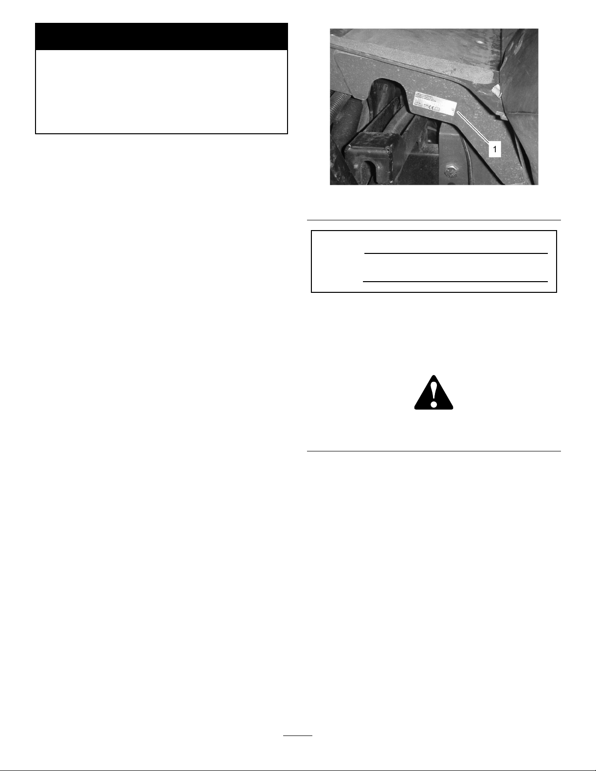
108–5278
1.ReadtheOperator’sManual.
93-7275
1.ReadtheOperator’sManual.
2.Donotusestartingaids.
105-3888
1.ReadtheOperator’sManual.
2.Tolocktheparkingbrake,securethebrakepedalswiththe
lockingpin,pressthebrakepedals,andpullouttheparking
brakeknob.
3.Tounlocktheparkingbrake,pressthebrakepedal.
114–9600
93-7272
1.Cutting/dismembermenthazard;fan—stayawayfrom
movingparts.
1.Enginecoolantunder
pressure.
2.Explosionhazard—read
theOperator’sManual.
106-6755
3.Warning—donottouch
thehotsurface.
4.Warning—readthe
Operator’sManual.
8
Page 9
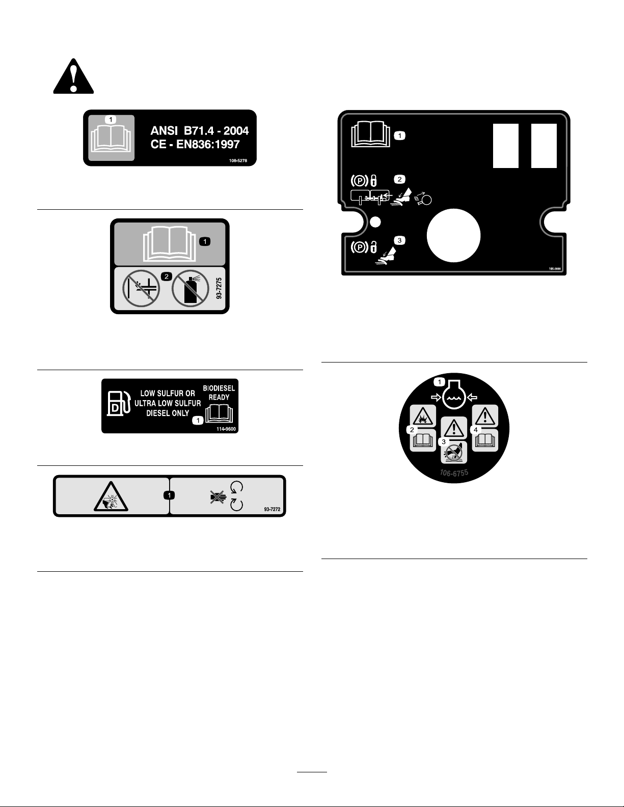
1.ReadtheOperator’s
Manual.
2.Engine—stop5.Engine—start
3.On
1.Machinespeed
2.Slow
105-9830
(AfxforCE)
1.Lock2.Unlock
105-7506
4.Engine—preheat
1.Hydraulicoil
93-6686
2.ReadtheOperator’s
Manual.
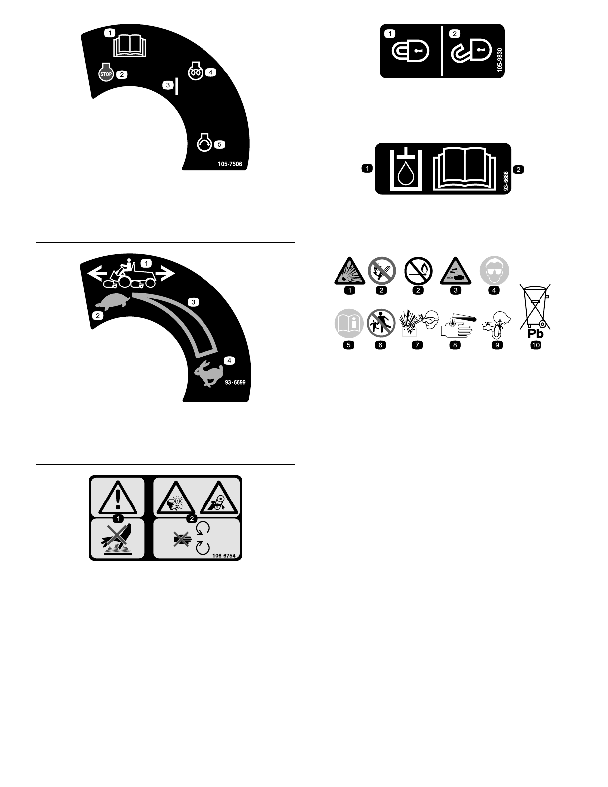
BatterySymbols
Someorallofthesesymbolsareonyourbattery
93-6699
3.Continuousvariable
setting
4.Fast
1.Explosionhazard
2.Nore,opename,or
smoking.
3.Causticliquid/chemical
burnhazard
4.Weareyeprotection9.Flusheyesimmediately
5.ReadtheOperator’s
Manual.
6.Keepbystandersasafe
distancefromthebattery .
7.Weareyeprotection;
explosivegasescan
causeblindnessandother
injuries
8.Batteryacidcancause
blindnessorsevereburns.
withwaterandgetmedical
helpfast.
10.Containslead;donot
discard.
106-6754
1.Warning—donottouchthehotsurface.
2.Cutting/dismembermenthazard,fanandentanglement
hazard,belt—stayawayfrommovingparts.
9
Page 10
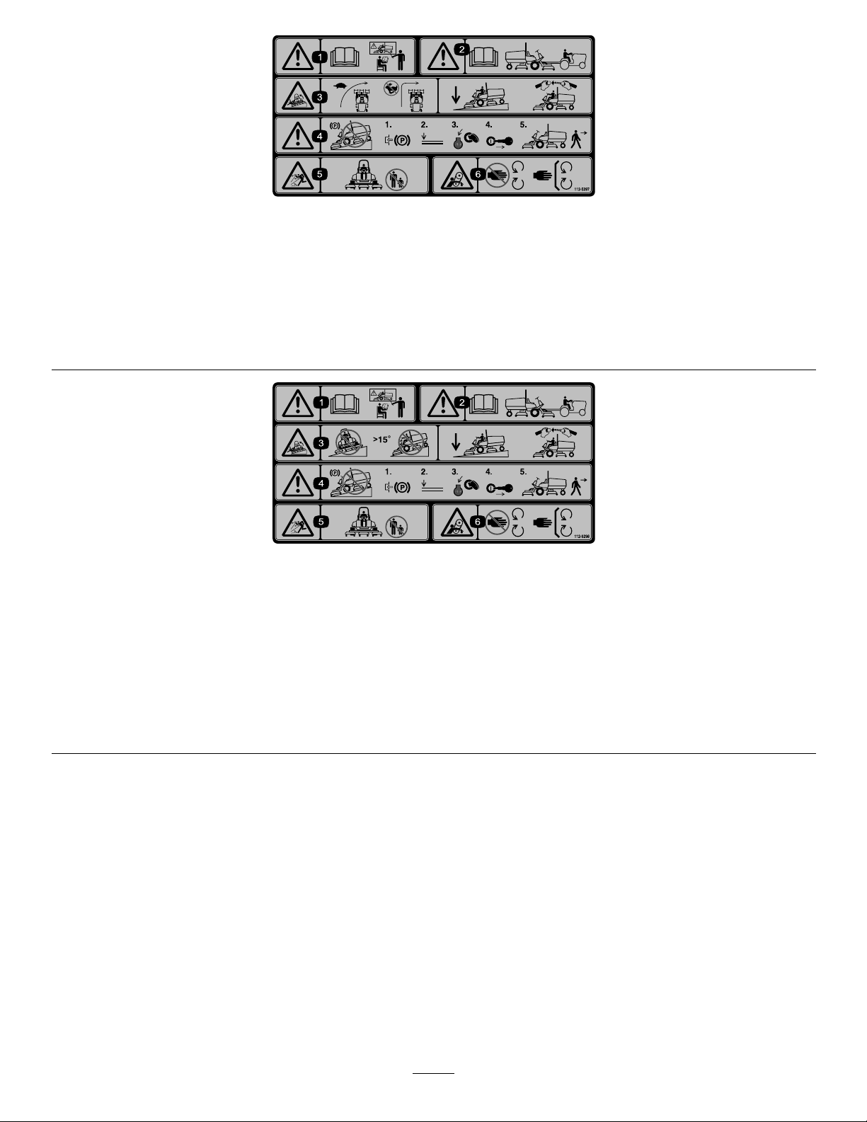
112-5297
1.Warning—readtheOperator’sManual,donotoperatethismachineunlessyouaretrained.
2.Warning—readtheOperator’sManualbeforetowingthemachine.
3.Tippinghazard—slowmachinebeforeturning,donotturnathighspeeds;lowerthecuttingunitwhendrivingdownslopes;usea
rolloverprotectionsystemandweartheseatbelt
4.Warning—donotparkthemachineonslopes;engagetheparkingbrake,lowerthecuttingunits,stoptheengineandremovethe
ignitionkeybeforeleavingthemachine.
5.Thrownobjecthazard—keepbystandersasafedistancefromthemachine.
6.Entanglementhazard,belt—donotremovecoverwhilepartsaremoving,keepallguardsinplace.
112–5298
(Afxoverpartno.112–5297forCE*
*ThissafetydecalincludesaslopewarningrequiredonthemachineforcompliancetotheEuropeanLawnMowerSafetyStandardEN836:1997.Theconservativemaximum
slopeanglesindicatedforoperationofthismachineareprescribedbyandrequiredbythisstandard.
1.Warning—readtheOperator’sManual.
2.Warning—readtheOperator’sManualbeforetowingthemachine.
3.Tippingandcrushinghazard—donotdrivemachineonaslopegreaterthan15degrees,weartheseatbelt,andlowerthe
cuttingunitwhendrivingdownslopes.
4.Warning—locktheparkingbrake,stoptheengine,andremovetheignitionkeybeforeleavingthemachine.
5.Thrownobjecthazard—keepbystandersasafedistancefromthemachine.
6.Entanglementhazard,belt—donotremovecoverwhilepartsaremoving,keepallguardsinplace.
10
Page 11
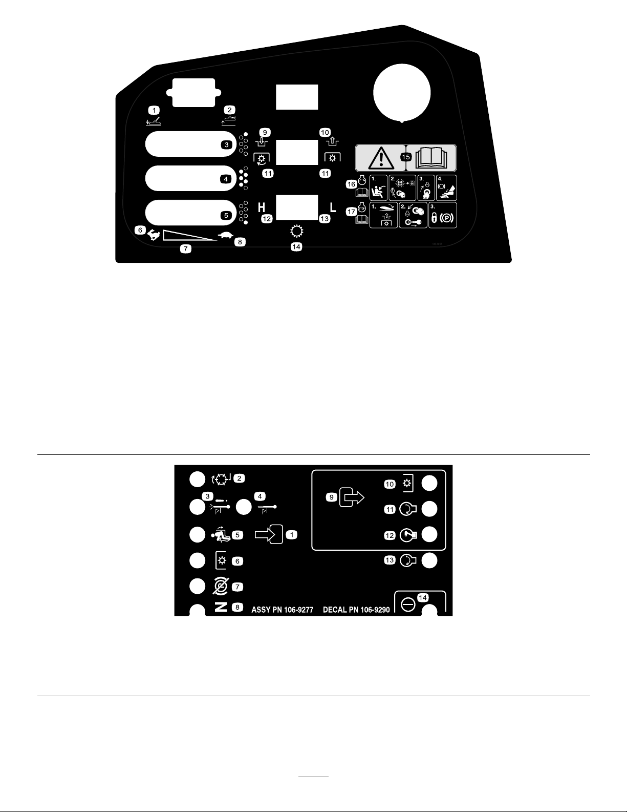
108-4044
1.Lowerthecuttingunit(s).
2.Raisethecuttingunit(s).11.PowerT ake-off(PTO)
3.Rightcuttingunit(GM4700-Donly)
4.Centercuttingunits
5.Leftcuttingunit(GM4700-Donly)
6.Fast
7.Continuousvariablesetting
8.Slow
9.Engage
10.Disengage
12.High
13.Low
14.Transmission
15.Warning—readtheOperator’sManual.
16.Tostarttheengine;sitintheoperator’sseat,turntheignition
keytoengine-onandwaitfortheglowplugindicatorlightto
extinguish,turntheignitionkeytoengine-start,releasethe
parkingbrake.
17.Tostoptheengine;lowerthedeckanddisengagethepower
take-off,turntheignitionkeytoengine-stopandremovethe
key,engagetheparkingbrake.
106–9290
1.Input5.Inseat
2.Backlap
3.Hightempshutdown
4.Hightempwarning8.Neutral12.ETR
6.PTOswitch10.PTO
7.Parkbrakeoff11.Start
11
9.Output13.Start
14.Power
Page 12
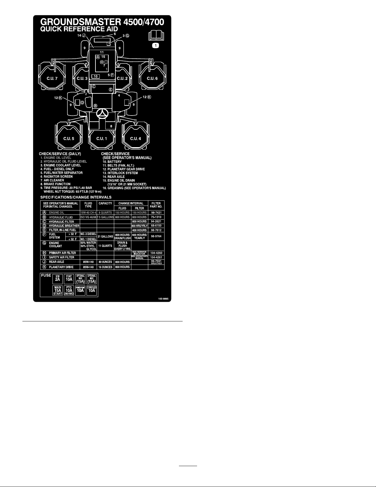
105-9895
12
Page 13
Setup
LooseParts
Usethechartbelowtoverifythatallpartshavebeenshipped.
ProcedureDescription
1
2
3
4
SeatKit,Model30398(soldseparately)
SeatSuspensionKit,Model30312
(Mechanical)or30313(Air)(sold
separately)
Seatbelt
Capscrew,7/16-20x1inch
Lockwasher,7/16inch
ManualTube1
R-clamp2
Nopartsrequired
Nopartsrequired
Operator’sManual
EngineOperator’sManual
PartsCatalog
OperatorTrainingMaterial
Qty.
1
1
1
2
2
–
–
2
1
1
1
Note:Determinetheleftandrightsidesofthemachinefromthenormaloperatingposition.
1.Mountthemanualtubetotheseatsuspensionwith
the2R-clampsincludedinlooseparts(Figure3).
Use
Installtheseat,seatbelt,andmanual
tube.
Greasethemachine.
Checktherearaxlelubricant,hydraulic
uid,andengineoillevels
Readthemanualsandwatchthe
trainingmaterialbeforeoperatingthe
machine.
1
InstallingtheSeat,SeatBelt,
andManualTube
Partsneededforthisprocedure:
1
SeatKit,Model30398(soldseparately)
SeatSuspensionKit,Model30312(Mechanical)or
1
30313(Air)(soldseparately)
1
Seatbelt
2
Capscrew,7/16-20x1inch
2
Lockwasher,7/16inch
1ManualTube
2R-clamp
Procedure
Themachineisshippedwithouttheseatassembly .
DeluxeSeatKit,ModelNo.30398,andSeatSuspension
Kit,ModelNo.30312or30313,mustbepurchasedand
installed.
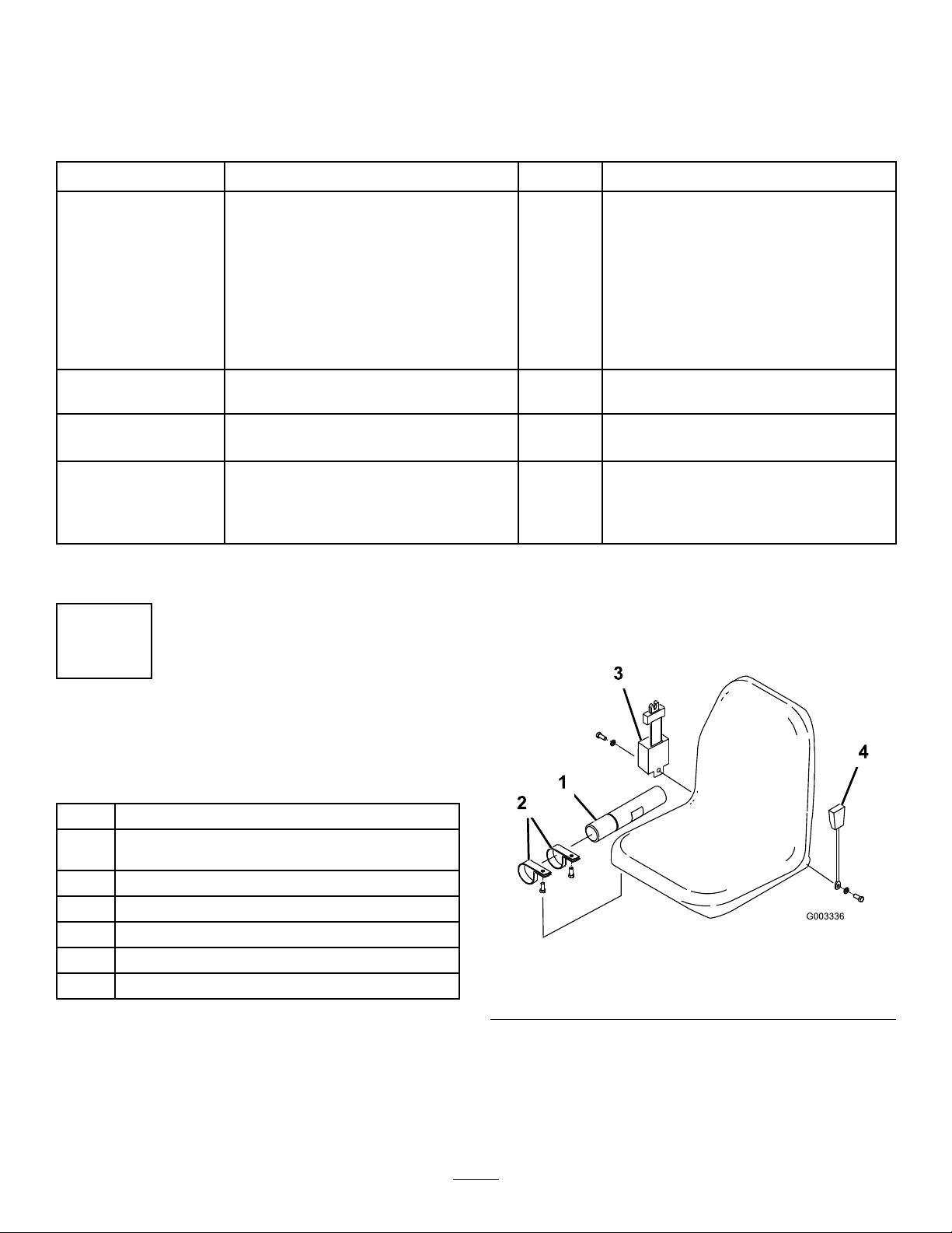
Figure3
1.Manualtube
2.R-clamp
3.Seatbeltretractor
4.Seatbeltbuckle
2.Installtheseatbelttoeachsideoftheseatwithabolt
andlockwasher,suppliedinlooseparts(Figure3).
Theseatbeltretractoristobemountedtotheright
sideoftheseatandtheseatbeltbuckletotheleft
side.
13
Page 14
Important:Makesurethattheseatswitchis
connectedtotheseatswitchconnectoronthe
harness.
3.Slidetheseatcompletelyforwardandbackwardto
ensureproperoperationandthatseatswitchwires
andconnectorsarenotpinchedordonocontactany
movingparts.
2
GreasingtheMachine
NoPartsRequired
Procedure
Beforethemachineisoperated,itmustbegreasedto
ensureproperlubrication.RefertoLubricationsection.
Failuretoproperlygreasethemachinewillresultin
prematurefailureofcriticalparts.
4
ReadingtheManualsand
ViewingtheTrainingMaterial
Partsneededforthisprocedure:
2
Operator’sManual
1
EngineOperator’sManual
1
PartsCatalog
1
OperatorTrainingMaterial
Procedure
1.Readthemanuals.
2.Viewthetrainingmaterial.
3.Storethedocumentationinasafeplace.
3
CheckingFluidLevels
NoPartsRequired
Procedure
1.Checktherearaxlelubricantlevelbeforetheengine
isrststarted,refertoCheckingtheRearAxle
LubricantinDriveSystemMaintenance.
2.Checkthehydraulicuidlevelbeforetheengineis
rststarted,refertoCheckingtheHydraulicFluid
LevelinOperation.
3.Checktheengineoillevelbeforeandaftertheengine
isrststarted,refertoCheckingtheEngineOil
LevelinOperation.
14
Page 15
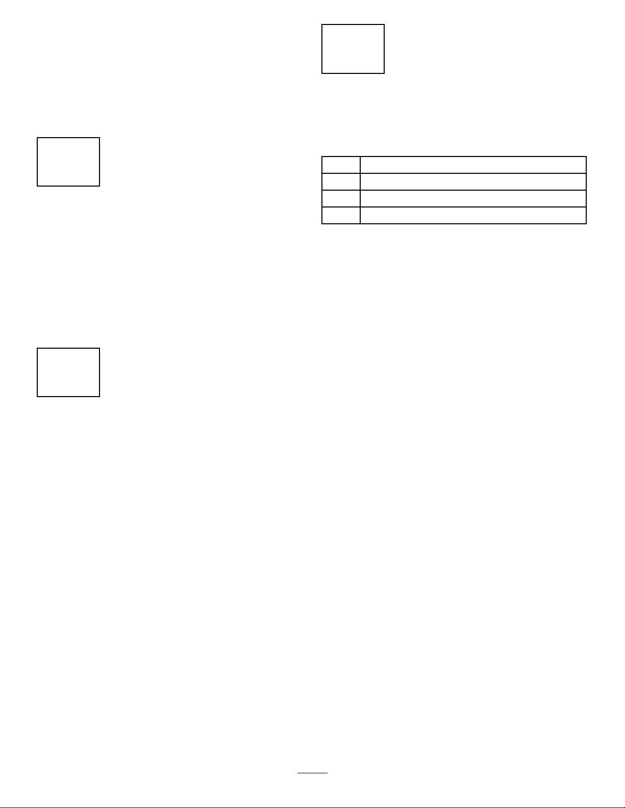
ProductOverview
1.Steeringwheel
2.Brakes5.Manualtube
3.Cuttingunit6.Hood/enginecompartment
4.Tractionpedal
Controls
TractionPedal
Thetractionpedal(Figure5)controlsforwardand
reverseoperation.Depressthetopofthepedaltomove
forwardandthebottomtomovebackward.Ground
speeddependsonhowfarthepedalisdepressed.For
noload,maximumgroundspeed,fullydepressthepedal
whilethethrottleisinFast.
Tostop,reduceyourfootpressureonthetractionpedal
andallowittoreturntothecenterposition.
ForwardSpeedControl
Presettheforwardspeedcontrol(Figure5)tolimit
theamountthetractionpedalcanbedepressedinthe
forwarddirectiontomaintainaconstantmowingspeed.
Figure4
7.ROPS(RolloverProtectionSystem)
ChargeIndicator
Thechargeindicator(Figure5)illuminateswhenthe
systemchargingcircuitmalfunctions.
EngineCoolantTemperatureWarning
Light
Thelight(Figure5)illuminatesandtheengineshuts
downwhencoolantreachesanexcessivelyhigh
temperature.
GlowPlugIndicatorLight
Whenlit,theglowplugindicatorlight(Figure5)
indicatesthattheglowplugsareon.
EngineOilPressureWarningLight
KeySwitch
Thekeyswitch(Figure5)hasthreepositions:Off,
On/Preheat,andStart.
Thelight(Figure5)illuminateswhentheengineoil
pressureisdangerouslylow .
15
Page 16
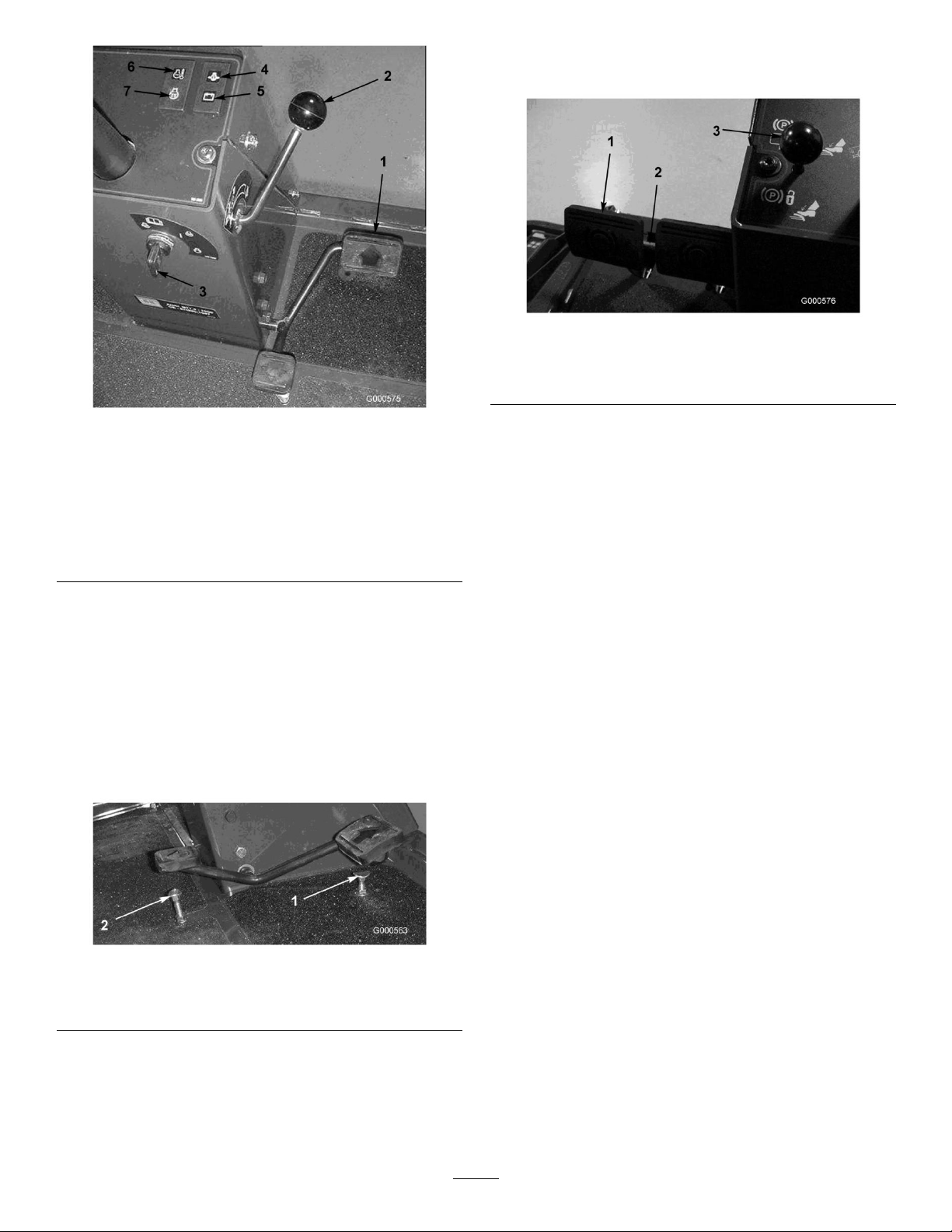
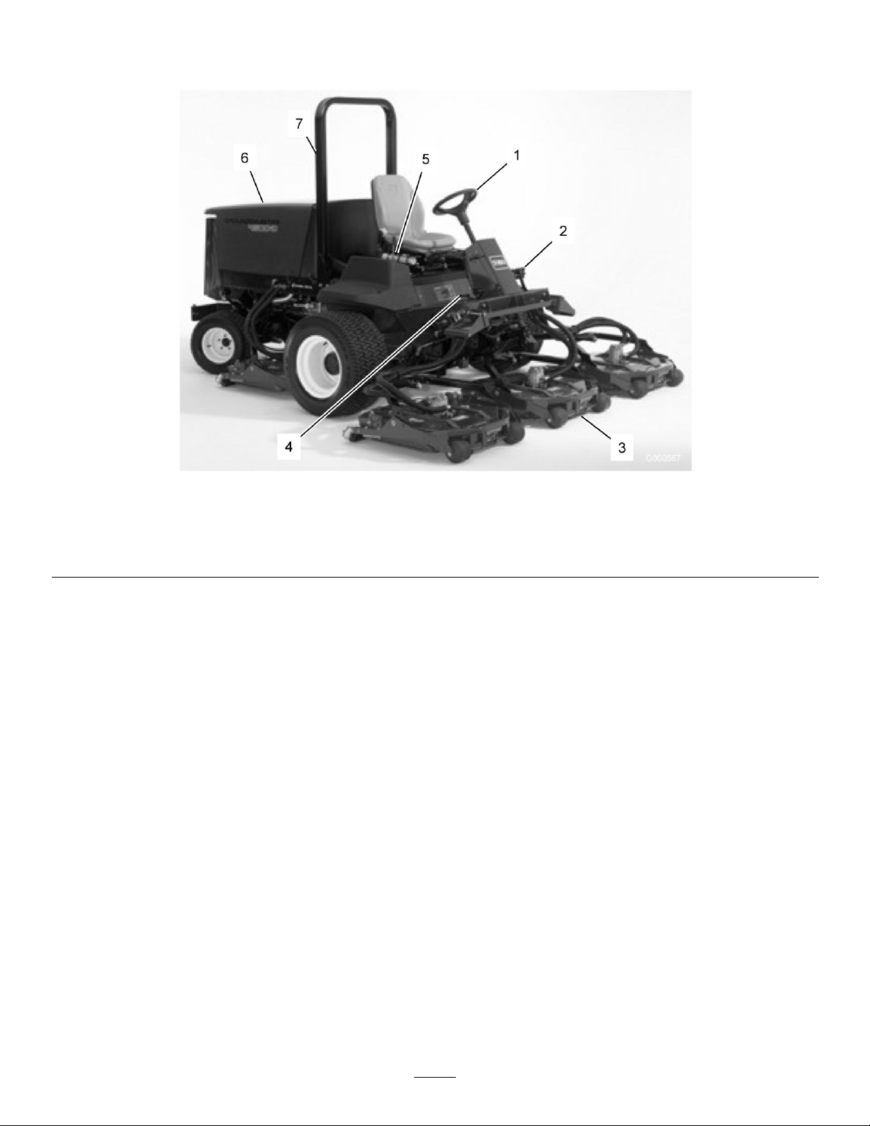
Figure5
1.Tractionpedal
2.Forwardspeedcontrol6.Enginecoolant
3.Keyswitch
4.Engineoilpressure
warninglight
5.Chargeindicator
7.Glowplugindicatorlight
temperaturewarning
light
obtainingbettersidehilltraction.Alatchconnectsthe
pedalsforparkingbrakeoperationandtransport.
Figure7
1.Brakepedals3.Parkingbrakelatch
2.Pedallockinglatch
PedalLockingLatch
Thepedallockinglatch(Figure7)connectsthepedals
togethertoengagetheparkingbrake.
ParkingBrakeLatch
SpeedLimiterScrews
Adjustthescrew(s)(Figure6)tolimittheamountthe
tractionpedalcanbedepressedintheforwardorreverse
directiontolimitspeed.
Important:Thespeedlimiterscrewmuststopthe
tractionpedalbeforethepumpreachesfullstroke
ordamagetothepumpmayoccur.
Figure6
1.Forwardspeedlimiter
screw
2.Reversespeedlimiter
screw
Aknobontheleftsideoftheconsoleactuatesthe
parkingbrakelock(Figure7).Toengagetheparking
brake,connectthepedalswiththelockinglatch,push
downonbothpedals,andpulltheparkingbrakelatch
out.Toreleasetheparkingbrake,depressbothpedals
untiltheparkingbrakelatchretracts.
ThrottleControl
Movethecontrol(Figure8orFigure9)forwardto
increasetheenginespeedandrearwardtodecreasethe
speed.
BrakePedals
Twofootpedals(Figure7)operateindividualwheel
brakesforturningassistance,parking,andtoaidin
16
Page 17
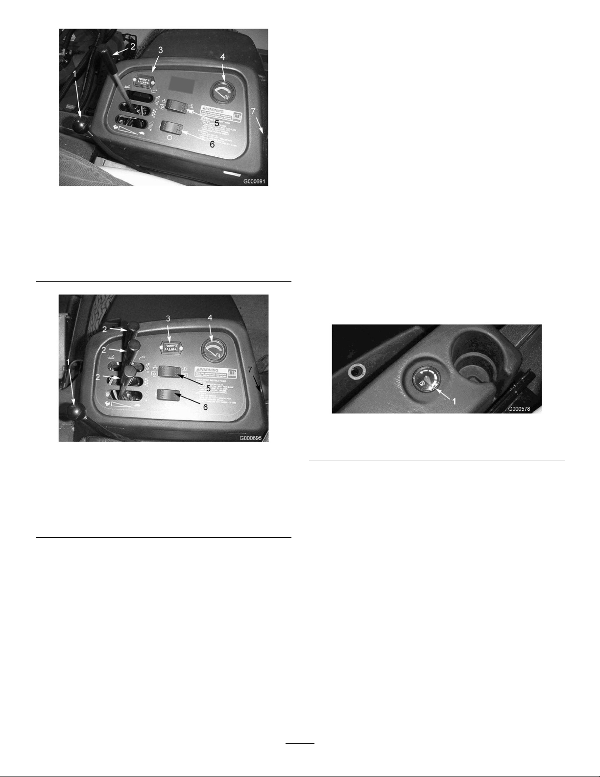
Model4500-D
PTOSwitch
ThePTOswitch(Figure8)hastwopositions:On
(engage)andOff(disengage).PushthePTOswitch
forwardtotheOnpositiontostarttheimplementor
cuttingunitblades.PushtheswitchbackwardtotheOff
positiontostopimplementoperation.
Hi-LoSpeedControl
Theswitch(Figure8)allowsthespeedrangetoincrease
fortransportofthemachine.Cuttingdeckswillnot
operateinhighrange.
Figure8
PowerPoint
1.Throttlecontrol
2.Liftlever
3.Hourmeter7.Powerpoint
4.Enginetemperaturegauge
Model4700-D
1.Throttlecontrol
2.Liftlever
3.Hourmeter7.Powerpoint
4.Enginetemperaturegauge
5.PTOswitch
6.Hi-Lospeedcontrol
Figure9
5.PTOswitch
6.Hi-Lospeedcontrol
Thepowerpoint(Figure8)isusedtopoweroptional12
voltelectricalaccessories.
FuelGauge
Thefuelgauge(Figure10)indicatestheleveloffuelin
thetank.
Figure10
1.Fuelgauge
CuttingUnitLiftLatch(CE)
Thecuttingunitliftlatch(Figure11orFigure12)locks
thecentervecuttingunitliftleverswhenthecutting
unitsareintheraisedposition.
LiftLever
Thelever(Figure8)raisesandlowersthecuttingunits.
HourMeter
Thehourmeter(Figure8)showsthetotalhoursthatthe
machinehasbeenoperated.
EngineTemperatureGauge
Thisgauge(Figure8)indicatestheenginecoolant
temperature.
17
Page 18

1.Cuttingunitliftlatch
1.Cuttingunitliftlatch
Figure11
Model4500-D
Figure12
Model4700-D
18
Page 19

Specications
Note:Specicationsanddesignaresubjecttochange
withoutnotice.
TractionUnitSpecications
4500-D4700-D
Widthofcut109inches(2.8m)150inches(3.8m)
Overallwidth,
cuttingunits
down
Overallwidth,
cuttingunitsup
(transport)
Overalllength145.8inches(370cm)145.8inches(370cm)
Heightwith
ROPS
Ground
clearance
TrackWidth,
front
TrackWidth,rear
Wheelbase
Weight(with
cuttingunitsand
nouids)
112.8inches(286cm)153.8inches(391cm)
88.25inches(224cm)88.25inches(224cm)
85inches(216cm)85inches(216cm)
6inches(15cm)6inches(15cm)
88.25inches(224cm)88.25inches(224cm)
55.5inches(141cm)55.5inches(141cm)
67-1/2inches(171cm)67-1/2inches(171cm)
4123lb(1400kg)4674lb(2120kg)
Attachments/Accessories
AselectionofToroapprovedattachmentsand
accessoriesareavailableforusewiththemachineto
enhanceandexpanditscapabilities.Contactyour
AuthorizedServiceDealerorDistributororgoto
www.Toro.comforalistofallapprovedattachments
andaccessories.
19
Page 20

Operation
Note:Determinetheleftandrightsidesofthe
machinefromthenormaloperatingposition.
Thismachineproducessoundlevelsinexcess
of85dBAattheoperator’searandcancause
hearinglossthroughextendedperiodsof
exposure.
Wearhearingprotectionwhenoperatingthis
machine.
Ifyouleavethekeyintheignitionswitch,
someonecouldaccidentlystarttheengineand
seriouslyinjureyouorotherbystanders.
Removethekeyfromtheignitionbeforeyoudo
anymaintenance.
Figure13
1.Dipstick
4.IftheoilisbelowtheFULLmark,removethell
cap(Figure14)andaddoiluntilthelevelreaches
theFULLmark.Donotoverll.
CheckingtheEngineOilLevel
ServiceInterval:Beforeeachuseordaily
Theengineisshippedwithoilinthecrankcase;
however,theoillevelmustbecheckedbeforeandafter
theengineisrststarted.
Thecrankcasecapacityisapproximately8qt.(7.6l)
withthelter.
Usehigh-qualityengineoilthatmeetsthefollowing
specications:
•APIClassicationLevelRequired:CH-4,CI-4or
higher.
•Preferredoil:SAE15W -40(above0°F)
•Alternateoil:SAE10W -30or5W-30(all
temperatures)
Note:ToroPremiumEngineoilisavailable
fromyourdistributorineither15W-40or10W-30
viscosity.Seethepartscatalogforpartnumbers.
1.Parkthemachineonalevelsurface.
2.Unlocktheenginecoverlatchesandopenthe
enginecover.
3.Removethedipstick,wipeitclean,installthe
dipstickintothetube,andpullitoutagain.
Figure14
1.Oilllcap
Note:Whenusingdifferentoil,drainalloldoil
fromthecrankcasebeforeaddingnewoil.
5.Installtheoilllcapanddipstick.
6.Closetheenginecoverandsecureitwiththelatches.
CheckingtheCoolingSystem
ServiceInterval:Beforeeachuseordaily
Checklevelofcoolantatthebeginningofeachday.
Capacityofsystemis2-3/4gal.(10.4l).
1.Carefullyremovetheradiatorcapandexpansion
tankcap(Figure15).
TheoillevelshouldbeuptotheFULLmark
(Figure13).
20
Page 21

ashpointandcoldowcharacteristicswhichwillease
startingandreducefuellterplugging.
Iftheenginehasbeenrunning,thepressurized,
hotcoolantcanescapeandcauseburns.
•Donotopentheradiatorcapwhenthe
engineisrunning.
•Usearagwhenopeningtheradiatorcap,
andopenthecapslowlytoallowsteamto
escape.
Figure15
1.Expansiontank
Useofsummergradefuelabove20°F(-7°C)will
contributetowardlongerfuelpumplifeandincreased
powercomparedtowintergradefuel.
Important:Donotusekeroseneorgasoline
insteadofdieselfuel.Failuretoobservethis
cautionwilldamagetheengine.
Fuelisharmfulorfatalifswallowed.Long-term
exposuretovaporscancauseseriousinjuryand
illness.
•Avoidprolongedbreathingofvapors.
•Keepfaceawayfromnozzleandgastankor
conditioneropening.
•Keepfuelawayfromeyesandskin.
BiodieselReady
Thismachinecanalsouseabiodieselblendedfuel
ofuptoB20(20%biodiesel,80%petrodiesel).The
petrodieselportionshouldbeloworultralowsulfur.
Observethefollowingprecautions:
•Thebiodieselportionofthefuelmustmeet
specicationASTMD6751orEN14214.
2.Checkthecoolantlevelintheradiator.Theradiator
shouldbelledtothetopofthellerneckandthe
expansiontanklledtotheFULLmark.
3.Ifthecoolantislow ,adda50/50mixtureofwater
andethyleneglycolanti-freeze.Donotusewater
onlyoralcohol/methanolbasecoolants.
4.Installtheradiatorcapandexpansiontankcap.
FillingtheFuelTank
Useonlyclean,freshdieselfuelorbiodieselfuelswith
low(<500ppm)orultralow(<15ppm)sulfurcontent.
Theminimumcetaneratingshouldbe40.Purchase
fuelinquantitiesthatcanbeusedwithin180daysto
ensurefuelfreshness.
Fueltankcapacity:21gallons(79l).
Usesummergradedieselfuel(No.2-D)attemperatures
above20°F(-7°C)andwintergrade(No.1-Dor
No.1-D/2-Dblend)belowthattemperature.Useof
wintergradefuelatlowertemperaturesprovideslower
•TheblendedfuelcompositionshouldmeetASTM
D975orEN590.
•Paintedsurfacesmaybedamagedbybiodiesel
blends.
•UseB5(biodieselcontentof5%)orlesserblends
incoldweather.
•Monitorseals,hoses,gasketsincontactwithfuelas
theymaybedegradedovertime.
•Fuellterpluggingmaybeexpectedforatimeafter
convertingtobiodieselblendsd.
•Contactyourdistributorifyouwishformore
informationonbiodiesel.
21
Page 22

Incertainconditions,fuelisextremely
ammableandhighlyexplosive.Areor
explosionfromfuelcanburnyouandothers
andcandamageproperty.
•Fillthefueltankoutdoors,inanopenarea,
whentheengineiscold.Wipeupanyfuel
thatspills.
•Neverllthefueltankinsideanenclosed
trailer.
•Neversmokewhenhandlingfuel,andstay
awayfromanopenameorwherefuel
fumesmaybeignitedbyaspark.
•Storefuelinanapprovedcontainerandkeep
itoutofthereachofchildren.Neverbuy
morethana180-daysupplyoffuel.
•Donotoperatewithoutentireexhaust
systeminplaceandinproperworking
condition.
Incertainconditionsduringfueling,static
electricitycanbereleasedcausingaspark
whichcanignitethefuelvapors.Areor
explosionfromfuelcanburnyouandothers
andcandamageproperty.
•Alwaysplacefuelcontainersontheground
awayfromyourvehiclebeforelling.
•Donotllfuelcontainersinsideavehicle
oronatruckortrailerbedbecauseinterior
carpetsorplastictruckbedlinersmay
insulatethecontainerandslowthelossof
anystaticcharge.
•Whenpractical,removeequipmentfromthe
truckortrailerandrefueltheequipment
withitswheelsontheground.
•Ifthisisnotpossible,thenrefuelsuch
equipmentonatruckortrailerfroma
portablecontainer,ratherthanfromafuel
dispensernozzle.
Figure16
1.Fueltankcap
2.Fillthetanktoabout1inch(25mm)belowthetop
ofthetank,notthellerneck,withNo.2diesel
fuel.Theninstallthecap.
Note:Ifpossible,llthefueltankaftereachuse.
Thiswillminimizepossiblebuildupofcondensation
insidethefueltank.
Undercertainconditions,dieselfuelandfuel
vaporsarehighlyammableandexplosive.A
reorexplosionfromfuelcanburnyouand
othersandcancausepropertydamage.
•Useafunnelandllthefueltankoutdoors,
inanopenarea,whentheengineisoffand
iscold.Wipeupanyfuelthatspills.
•Donotllthefueltankcompletelyfull.Add
fueltothefueltankuntilthelevelis1in.(25
mm)belowthetopofthetank,nottheller
neck.Thisemptyspaceinthetankallows
thefueltoexpand.
•Neversmokewhenhandlingfuel,andstay
awayfromanopenameorwherefuel
fumesmaybeignitedbyaspark.
•Storefuelinaclean,safety-approved
containerandkeepthecapinplace.
•Ifafueldispensernozzlemustbeused,keep
thenozzleincontactwiththerimofthefuel
tankorcontaineropeningatalltimesuntil
fuelingiscomplete.
1.Removethefueltankcap(Figure16).
CheckingtheHydraulicFluid
Level
ServiceInterval:Beforeeachuseordaily
Themachinesreservoirislledatthefactorywith
approximately7.5U .S.gallons(13.2l)ofhighquality
22
Page 23

hydraulicuid.Checkthelevelofthehydraulicuid
beforetheengineisrststartedanddailythereafter.
Therecommendedreplacementuidisasfollows:
ToroPremiumAllSeasonHydraulicFluid(Availablein5
gallonpailsor55gallondrums.SeepartscatalogorT oro
distributorforpartnumbers.)
Alternateuids:IftheT orouidisnotavailable,other
uidsmaybeusedprovidedtheymeetallthefollowing
materialpropertiesandindustryspecications.Wedo
notrecommendtheuseofsyntheticuid.Consult
withyourlubricantdistributortoidentifyasatisfactory
productNote:T orowillnotassumeresponsibilityfor
damagecausedbyimpropersubstitutions,souseonly
productsfromreputablemanufacturerswhowillstand
behindtheirrecommendation.
HighViscosityIndex/LowPourPointAnti-wearHydraulic
Fluid,ISOVG46
MaterialProperties:
Viscosity,ASTMD445cSt@40°C44to48
ViscosityIndexASTM
D2270
PourPoint,ASTMD97-34°Fto-49°F
IndustrySpecications:
VickersI-286-S(QualityLevel),VickersM-2950-S
(QualityLevel),DenisonHF-0
cSt@100°C7.9to8.5
140to160
Note:Manyhydraulicuidsarealmostcolorless,
makingitdifculttospotleaks.Areddyeadditivefor
thehydraulicsystemoilisavailablein2/3oz.(20ml)
bottles.Onebottleissufcientfor4-6gal(15-221)
ofhydraulicoil.Orderpartno.44-2500fromyour
authorizedTorodistributor.
BiodegradableHydraulicFluid-Mobil224H
ToroBiodegradableHydraulicFluid(Availablein5
gallonpailsor55gallondrums.SeepartscatalogorT oro
distributorforpartnumbers.)
Alternateuid:MobilEAL224H
Note:Thisisvegetable-oilbasedbiodegradableoil
testedandapprovedbyToroforthismodel.Thisuid
isnotasresistanttohightemperaturesasstandard
uidsomakesuretofollowtherecommendeduid
changeintervalswiththisuid.Contamination
bymineral-basedhydraulicuidswillchangethe
biodegradabilityandtoxicityofthisoil.Whenchanging
fromstandarduidtothebiodegradabletype,be
certaintofollowtheapprovedushingprocedure.
ContactyourlocalToroDistributorfordetails.
1.Positionthemachineonalevelsurface,lowerthe
cuttingunits,stoptheengine,andremovethekey.
2.Cleantheareaaroundthellerneckandcapofthe
hydraulictank(Figure17).Removethecapfrom
thellerneck.
Figure17
1.Hydraulictankcap
3.Removethedipstickfromthellerneckandwipe
itwithacleanrag.Insertthedipstickintotheller
neck;thenremoveitandchecktheuidlevel.The
uidlevelshouldbebetweenthetwomarksonthe
dipstick.
4.Ifthelevelislow ,addtheappropriateuidtoraise
theleveltotheuppermark.
5.Installthedipstickandcapontothellerneck.
CheckingtheTirePressure
ServiceInterval:Beforeeachuseordaily
Thetiresareover-inatedforshipping.Therefore,
releasesomeoftheairtoreducethepressure.The
correctairpressureinthetiresis20psi(138kPa).
Checkthetirepressuredaily.
Important:Maintaintherecommendedpressure
inalltirestoensureagoodquality-of-cut
andpropermachineperformance.Donot
under-inate.
StartingandStoppingthe
Engine
StartingtheEngine
Important:Thefuelsystemmustbebledifanyof
thefollowingsituationshaveoccurred:
•Theenginehasceasedrunningduetolackoffuel.
•Maintenancehasbeenperformeduponthefuel
systemcomponents.
23
Page 24

RefertoBleedingtheFuelSystemin,page.
1.Removeyourfootfromthetractionpedaland
ensurethatitisinneutral.Ensurethattheparking
brakeisset.
2.Movethethrottlecontroltothelowidleposition.
3.TurntheignitionkeytotheRunposition.Theglow
indicatorwilllight.
1.MovethethrottlecontrolbackwardtotheSlow
position.
2.MovethePTOlevertotheOffposition.
3.Settheparkingbrake.
4.RotatetheignitionkeytoOff.
5.Removethekeyfromtheswitchtoprevent
accidentalstarting.
4.Whentheglowindicatordims,turntheignitionkey
totheStartposition.Releasethekeyimmediately
whentheenginestartsandallowittoreturnto
theRunposition.Movethethrottlecontroltothe
desiredposition.
Important:Donotrunthestartermotor
morethan15secondsatatimeorpremature
starterfailuremayresult.Iftheenginefailsto
startafter15seconds,turnthekeytotheOff
position,recheckthecontrolsandprocedures,
wait15additionalseconds,andrepeatthe
startingprocedure.
Whenthetemperatureislessthan20°F(-7°C),the
startermotorcanberunfor30secondsonthen60
secondsofffor2attempts.
5.Whentheengineisstartedforthersttime,or
afteranoverhauloftheengine,transmission,or
axle,operatethemachineinforwardandreversefor
oneortwominutes.Alsooperatetheliftleverand
PTOlevertoensureproperoperationofallparts.
Turnthesteeringwheeltotheleftandrightto
checksteeringresponse.Thenshuttheengineoff
andcheckforoilleaks,looseparts,andanyother
noticeabledifculties.
CheckingtheInterlock
Switches
ServiceInterval:Beforeeachuseordaily
Ifsafetyinterlockswitchesaredisconnected
ordamagedthemachinecouldoperate
unexpectedlycausingpersonalinjury.
•Donottamperwiththeinterlockswitches.
•Checktheoperationoftheinterlock
switchesdailyandreplaceanydamaged
switchesbeforeoperatingthemachine.
Themachinehasinterlockswitchesintheelectrical
system.Theseswitchesaredesignedtostoptheengine
whenoperatorgetsoffoftheseatwhenthetraction
pedalisdepressed.However,theoperatormaygetoff
oftheseatwhiletheengineisrunningandthetraction
pedalisinneutral.Althoughtheenginewillcontinue
torunifthePTOleverisdisengagedandthetraction
pedalisreleased,itisstronglyrecommendedthatthe
enginebestoppedbeforerisingfromtheseat.
Shuttheengineoffandwaitforallmoving
partstostopbeforecheckingforoilleaks,loose
parts,andothermalfunctions.
StoppingtheEngine
Important:Allowenginetoidlefor5minutes
beforeshuttingitoffafterafullloadoperation.
Thisallowstheturbochargertocooldownbefore
shuttingtheengineoff.Failuretodosomaylead
toturbo-chargertrouble.
Note:Lowercuttingunitstothegroundwhenever
machineisparked.Thisrelievesthehydraulicloadfrom
thesystem,preventswearonsystempartsandalso
preventsaccidentalloweringofthecuttingunits.
Tochecktheoperationoftheinterlockswitches,
performthefollowingprocedure:
1.Drivethemachineslowlytoalarge,relativelyopen
area.Lowerthecuttingunit,stoptheengine,and
applytheparkingbrake.
2.Sitontheseatanddepressthetractionpedal.Try
tostarttheengine.Theengineshouldnotcrank.
Iftheenginecranks,thereisamalfunctioninthe
interlocksystemthatshouldbecorrectedbefore
beginningoperation.
3.Sitontheseatandstarttheengine.Risefromthe
seatandmovethePTOlevertoOn.ThePTO
shouldnotengage.IfthePTOengages,thereisa
malfunctionintheinterlocksystemthatshouldbe
correctedbeforebeginningoperation.
4.Sitontheseat,engagetheparkingbrakeandstart
theengine.Movethetractionpedaloutofthe
neutralposition.Theengineshouldkill.Ifthe
24
Page 25

enginedoesnotkill,thereisamalfunctioninthe
interlocksystemthatshouldbecorrectedbefore
beginningoperation.
Note:Thesafetyinterlockswitchescanalsobe
checkedusingthediagnosticLED’sontheSCM.
PushingorTowingthe
Machine
Inanemergency,themachinecanbemovedforwardby
actuatingthebypassvalveinthevariabledisplacement
hydraulicpumpandpushingortowingthemachine.
Donotpushortowthemachineformorethan1/4
mile(0.4km).
Important:Donotpushortowthemachine
fasterthan2-3MPH(3-4.8km/h)becauseinternal
transmissiondamagemayoccur.Thebypassvalve
mustbeopenwheneverthemachineispushedor
towed.
Important:Ifthemachinemusttobepushedor
towedinreverse,thecheckvalveinthefour-wheel
drivemanifoldmustalsobebypassed.T obypass
thecheckvalve,connectahoseassembly(Hose
PartNo.95-8843,CouplerFittingNo.95-0985
[Qty.2],andHydraulicFittingNo.340-77[Qty .2])
tothereversetractionpressuretestportandthe
reversefour-wheeldrivepressureport.
1.Openhoodandremovethecentershroud
2.Rotatethebypassvalve90°(1/4turn)ineither
directiontoopenandallowoiltobypassinternally
(Figure18).Becauseuidisbypassed,themachine
canbeslowlymovedwithoutdamagingthe
transmission.Notethepositionofthevalvewhen
openingorclosing.
Figure18
1.Bypassvalve
3.Rotatethebypassvalve90°(1/4turn)backbefore
startingtheengine.Donotexceed5-8ft.-lb.
(7-11N·m)torquetoclosethevalve.
JackingPoints
•Onthefrontofthemachineontheframeonthe
insideofeachdrivetire
•Ontherearofthemachineatthecenteroftheaxle
TieDowns
•Oneachsideoftheframeunderthefrontsteps
•Therearbumper
OperatingCharacteristics
Practicedrivingthemachinebecauseithasahydrostatic
transmissionanditscharacteristicsaredifferentthan
manyturfmaintenancemachines.Somepointsto
considerwhenoperatingthetractionunit,cutting
units,orotherimplementsarethetransmission,engine
speed,loadonthecuttingbladesorotherimplement
components,andtheimportanceofthebrakes.
Tomaintainenoughpowerforthetractionunitand
implementwhileoperating,regulatethetractionpedal
tokeeptheengineRPMhighandsomewhatconstant.
Agoodruletofollowistodecreasethegroundspeed
astheloadontheimplementincreases,andincreasethe
groundspeedastheloaddecreases.
Therefore,allowthetractionpedaltomovebackward
astheengineRPMdecreases,anddepressthepedal
slowlyastheRPMincreases.Bycomparison,when
drivingfromoneworkareatoanother,withnoload
andcuttingunitraised,havethethrottleintheFast
positionanddepressthetractionpedalslowlybutfully
toattainmaximumgroundspeed.
25
Page 26

Anothercharacteristictoconsideristheoperation
ofthepedalsthatareconnectedtothebrakes.The
brakescanbeusedtoassistinturningthemachine.
However,usethemcarefully,especiallyonsoftor
wetgrassbecausetheturfmaybetornaccidentally .
Anotherbenetofthebrakesistomaintaintraction.
Forexample,insomeslopeconditions,theuphillwheel
slipsandlosestraction.Ifthissituationoccurs,depress
theuphillturnpedalgraduallyandintermittentlyuntil
theuphillwheelstopsslipping,thus,increasingtraction
onthedownhillwheel.
moduleenergizesoutputsincludingPTO ,Starter,and
ETR(energizetorun)solenoid.
Themoduleisdividedintoinputsandoutputs.Inputs
andoutputsareidentiedbygreenLEDindicators
mountedontheprintedcircuitboard.
Thestartcircuitinputisenergizedby12VDC.All
otherinputsareenergizedwhenthecircuitisclosedto
ground.EachinputhasaLEDthatisilluminatedwhen
thespeciccircuitisenergized.UsetheinputLED’ s
forswitchandinputcircuittroubleshooting.
Useextracarewhenoperatingthemachineonslopes.
Makesurethattheseatlatchisproperlysecuredandthe
seatbeltisbuckled.Driveslowlyandavoidsharpturns
onslopestopreventrollovers.Forsteeringcontrol,the
cuttingunitmustbeloweredwhengoingdownhill.
Thisproductisdesignedtodriveobjectsinto
thegroundwheretheyloseenergyquickly
ingrassareas.However,carelessoperation,
combinedwithterrainangle,ricochets,or
improperlypositionedsafetyguardcanleadto
thrownobjectinjuries.
•Whenapersonorpetappearssuddenlyinor
nearthemowingarea,stopmowing.
•Donotresumemowinguntiltheareais
cleared.
Important:Allowenginetoidlefor5minutes
beforeshuttingitoffafterafullloadoperation.
Thisallowstheturbochargertocooldownbefore
shuttingtheengineoff.Failuretodosomaylead
toturbo-chargertrouble.
Outputcircuitsareenergizedbyanappropriatesetof
inputconditions.ThethreeoutputsincludePTO,ETR,
andSTART.OutputLED’smonitorrelaycondition
indicatingthepresenceofvoltageatoneofthree
specicoutputterminals.
Outputcircuitsdonotdetermineoutputdevice
integritysoelectricaltroubleshootingincludesoutput
LEDinspectionandconventionaldeviceandwire
harnessintegritytesting.Measuredisconnected
componentimpedance,impedancethroughwire
harness(disconnectatSCM),orbytemporarily"test
energizing"thespeciccomponent.
TheSCMdoesnotconnecttoanexternalcomputeror
handhelddevice,cannotbere-programmed,anddoes
notrecordintermittentfaulttroubleshootingdata.
ThedecalontheSCMonlyincludessymbols.Three
LEDoutputsymbolsareshownintheoutputbox.
AllotherLED’sareinputs.Figure19identiesthe
symbols.
Beforestoppingtheengine,disengageallcontrolsand
movethethrottletoSlow .MovingthethrottletoSlow
reduceshighengineRPM,noise,andvibration.Turn
thekeytoOfftostoptheengine.
StandardControlModule
(SCM)
TheStandardControlModuleisa"potted"electronic
deviceproducedina"onesizetsall"conguration.
Themoduleusessolidstateandmechanical
componentstomonitorandcontrolstandardelectrical
featuresrequiredforsafeproductoperation.
Themodulemonitorsinputsincludingneutral,parking
brake,PTO ,start,backlap,andhightemperature.The
26
Page 27

1.Input5.Inseat
2.Backlap
3.Hightempshutdown
4.Hightempwarning(Not
used)
6.PTOswitch10.PTO
7.Parkbrakeoff11.Start
8.Neutral12.ETR
Figure19
9.Output13.Start
14.Power
HerearethelogicaltroubleshootingstepsfortheSCM
device.
1.Determinetheoutputfaultyouaretryingtoresolve
(PTO,START,orETR).
2.Movekeyswitchto"ON"andensurethered
"power"LEDisilluminated.
3.MoveallinputswitchestoensureallLED’schange
state.
4.Positioninputdevicesatappropriatepositionto
achievetheappropriateoutput.Usethefollowing
logiccharttodeterminetheappropriateinput
condition.
5.IfspecicoutputLEDisilluminatedwithout
appropriateoutputfunction,checkoutputharness,
connections,andcomponent.Repairasrequired.
6.IfspecicoutputLEDisnotilluminated,check
bothfuses.
7.IfspecicoutputLEDisnotilluminatedandinputs
areinappropriatecondition,installnewSCMand
determineiffaultdisappears.
Eachrow(across)inthelogicchartbelowidenties
inputandoutputrequirementsforeachspecic
productfunction.Productfunctionsarelistedin
theleftcolumn.Symbolsidentifyspeciccircuit
conditionincluding:energizedtovoltage,closedto
ground,andopentoground.
Note:-Indicatesacircuitclosedtoground.-LEDON
OIndicatesacircuitopentogroundorde-energized-LEDOFF
+Indicatesanenergizedcircuit(clutchcoil,solenoid,orstartinput)LEDON.
""ABlankindicatesacircuitthatisnotinvolvedwiththelogic.
Totroubleshoot,turnonthekeywithoutstarting
theengine.Identifythespecicfunctionthatdoes
notworkandworkacrossthelogicchart.Inspect
theconditionofeachinputLED’stoensureit
matchesthelogicchart.
IftheinputLED’ sarecorrect,checktheoutput
LED.IftheoutputLEDisilluminatedbutthe
27
Page 28

deviceisnotenergized,measureavailablevoltageat
theoutputdevice,continuityofthedisconnected
device,andpotentialvoltageonthegroundcircuit
(oatingground).Repairswillvarydependingon
yourndings.
OperatingTips
MowWhenGrassisDry
Moweitherinthelatemorningtoavoidthedew ,which
causesgrassclumping,orinlateafternoontoavoidthe
damagethatcanbecausedbydirectsunlightonthe
sensitive,freshlymowedgrass.
SelecttheProperHeight-of-CutSetting
toSuitConditions
Removeapproximately1in.(25mm)ornomorethan
1/3ofthegrassbladewhencutting.Inexceptionally
lushanddensegrass,youmayhavetoraisethe
height-of-cuttothenextsetting.
allowedtobuildupinthemowerhousing,cutting
performancewilldecrease.
Note:Lowercuttingunitstothegroundwhenever
machineisparked.Thisrelievesthehydraulicloadfrom
thesystem,preventswearonsystempartsandalso
preventsaccidentalloweringofthecuttingunits.
MowatProperIntervals
Undermostnormalconditionsyouwillneedtomow
approximatelyevery4-5days.Butremember,grass
growsatdifferentratesatdifferenttimes.Thismeans
thatinordertomaintainthesameheight-of-cut,which
isagoodpractice,youwillneedtocutmorefrequently
inearlyspring;asthegrassgrowthrateslowsinmid
summer,cutonlyevery8-10days.Ifyouareunableto
mowforanextendedperiodduetoweatherconditions
orotherreasons,mowrstwiththeheight-of-cutata
highlevel;thenmowagain2-3dayslaterwithalower
heightsetting.
AlwaysMowwithSharpBlades
Asharpbladecutscleanlyandwithouttearingor
shreddingthegrassbladeslikeadullblade.Tearingand
shreddingcausesthegrasstoturnbrownattheedges
whichimpairsgrowthandincreasessusceptibilityto
diseases.
Transporting(Groundsmaster4700–D
Only)
Usethetworeartransportlatcheswhentransporting
overlongdistances,roughterrain,orwhentrailering.
AfterOperating
Toensureoptimumperformance,cleantheunderside
ofthemowerhousingaftereachuse.Ifresidueis
28
Page 29

Maintenance
Note:Determinetheleftandrightsidesofthemachinefromthenormaloperatingposition.
RecommendedMaintenanceSchedule(s)
MaintenanceService
Interval
Aftertherst8hours
Aftertherst50hours
Aftertherst200hours
Beforeeachuseordaily
Every50hours
Every100hours
Every150hours
Every200hours
MaintenanceProcedure
•Torquethewheelnuts.
•Changetheengineoilandlter.
•Changetheplanetarygeardriveoil.
•Changetherearaxlelubricant.
•Changethehydrauliclters.
•Checktheengineoillevel.
•Checkthecoolingsystem.
•Checkthehydraulicuidlevel.
•Checkthetirepressure.
•Checktheinterlockswitches.
•Drainwaterorothercontaminantsfromthewaterseparator.
•Removedebrisfromtheenginearea,oilcooler,andradiator.
•Inspectthehydrauliclinesandhosesforleaks,kinkedlines,loosemounting
supports,wear,loosettings,weatherdeterioration,andchemicaldeterioration.
•Greasethebearingsandbushings.
•Checkthebatterycondition.
•Checktheconditionandtensionofthealternatorbelt.
•Changetheengineoilandlter.
•Torquethewheelnuts.
•Cleanthesparkarrestormufer.
Every400hours
Every800hours
Beforestorage
Yearly
Important:Refertoyourengine
maintenanceprocedures.
•Servicetheaircleaner.(Servicetheaircleanerearlieriftheaircleanerindicator
showsred.Serviceitmorefrequentlyinextremelydirtyordustyconditions.)
•Checkthefuellinesandconnections.
•Replacethefuelltercanister.
•Checktheplanetarygeardriveoillevel(soonerifexternalleakageisnoticed).
•Checktherearaxlelubricantlevel.
•Drainandcleanthefueltank.
•Changetheplanetarygeardriveoil.
•Changetherearaxlelubricant.
•Checktherearwheeltoe-in.
•Changethehydraulicuid.
•Changethehydrauliclters.
•Drainandcleanthefueltank.
•Checkthetirepressure.
•Checkallfasteners.
•Greaseoroilallgreasettingsandpivotpoints.
•Paintchippedsurfaces.
•Checkthefuellinesandconnections.
•Changetheplanetarygeardriveoil.
•Checktherearwheeltoe-in.
Operator’sManual
andcuttingunit
Operator’sManual
foradditional
29
Page 30

DailyMaintenanceChecklist
Duplicatethispageforroutineuse.
Maintenance
CheckItem
Checkthe
safetyinterlock
operation.
Checkthebrake
operation.
Checktheengine
oilandfuellevel.
Checkthecooling
systemuidlevel.
Drainthe
water/fuel
separator.
Checktheair
lterrestriction
indicator.
Checkthe
radiator,oilcooler,
andscreenfor
debris.
Checkunusual
enginenoises.
Checkunusual
operatingnoises.
Checkthe
hydraulicsystem
oillevel.
Checkhydraulic
hosesfor
damage.
Checkforuid
leaks.
Checkthetire
pressure.
Checkthe
instrument
operation.
Lubricateall
greasettings.
Touch-up
damagedpaint.
1
2
Fortheweekof:
Mon.Tues.Wed.Thurs.Fri.
Sat.Sun.
1.Checktheglowplugandinjectornozzlesifhardstarting,excesssmoke,orroughrunningisnoted.
2.Immediatelyaftereverywashing,regardlessoftheintervallisted.
30
Page 31

ServiceIntervalChart
Figure21
Ifyouleavethekeyintheignitionswitch,someonecouldaccidentlystarttheengineandseriously
injureyouorotherbystanders.
Removethekeyfromtheignitionbeforeyoudoanymaintenance.
31
Page 32

Premaintenance
Lubrication
Procedures
GreasingtheBearingsand
RemovingtheHood
Togainadditionalaccesstoenginecompartment,the
hoodmayberemovedfromtractionunit.
1.Releasehoodlatches(Figure22)andraisehood.
Figure22
1.Hoodlatch
2.Unhooklanyardfromhoodpin,removepinand
slidehoodtubesrearwardoffguides(Figure23).
Bushings
ServiceInterval:Every50hours
Themachinehasgreasettingsthatmustbelubricated
regularlywithNo.2GeneralPurposeLithiumBase
Grease.Ifthemachineisoperatedundernormal
conditions,lubricateallbearingsandbushingsafter
every50hoursofoperationorimmediatelyafterevery
washing.
Thegreasettinglocationsandquantitiesareasfollows:
•Brakeshaftpivotbearings(5)(Figure24)
Figure24
•Rearaxlepivotbushings(2)(Figure25)
1.Hoodpin
Figure23
Figure25
•Steeringcylinderballjoints(2)(Figure26)
32
Page 33

Figure26
1.Topttingonkingpin
•Tierodballjoints(2)(Figure26)
•Kingpinbushings(2)(Figure26).Thetoptting
onthekingpinshouldonlybelubricated
annually(2pumps).
•Liftarmbushings(1perdeck)(Figure27)
Figure28
•Cuttingunitcarrierarmbushings(1percuttingunit)
(Figure28)
•Rearrollerbearings(2percuttingunit)(Figure29
orFigure30)
Figure29
Important:Makesurethegreasegroovein
eachrollermountalignswiththegreaseholein
eachendoftherollershaft.Tohelpalignthe
grooveandhole,thereisalsoanalignmentmark
ononeendoftherollershaft.
Figure27
•Liftcylinderbushings(2perdeck)(Figure27)
•Cuttingunitspindleshaftbearings(1percutting
unit)(Figure28)
Note:Onrollersequippedwithushgrease
ttings(Figure30)agreasegunnozzleadapteris
required.OrderT oroPartNo.107-1998fromyour
AuthorizedToroDistributor.
Figure30
33
Page 34

EngineMaintenance
ServicingtheAirCleaner
whichcouldforcedirtthroughthelterintothe
intaketract.
Thiscleaningprocesspreventsdebrisfrommigrating
intotheintakewhentheprimarylterisremoved.
ServiceInterval:Every400hours
Checktheaircleanerbodyfordamagewhichcould
causeanairleak.Replaceifdamaged.Checkthewhole
intakesystemforleaks,damageorloosehoseclamps.
Servicetheaircleanerlteronlywhentheservice
indicator(Figure31)requiresit.Changingtheairlter
beforeitisnecessaryonlyincreasesthechanceofdirt
enteringtheenginewhenthelterisremoved.
Figure31
1.Aircleanerindicator
3.Removeandreplacetheprimarylter(Figure33).
Cleaningoftheusedelementisnotrecommended
duetothepossibilityofdamagetotheltermedia.
Inspectthenewlterforshippingdamage,checking
thesealingendofthelterandthebody.Donot
useadamagedelement.Insertthenewlterby
applyingpressuretotheouterrimoftheelementto
seatitinthecanister.Donotapplypressuretothe
exiblecenterofthelter.
Important:Besurethecoverisseatedcorrectly
andsealswiththeaircleanerbody.
1.Pullthelatchoutwardandrotatetheaircleaner
covercounterclockwise(Figure32).
Figure32
1.Aircleanerlatch2.Aircleanercover
2.Removethecoverfromtheaircleanerbody .Before
removingthelter,uselowpressureair(40psi,
cleananddry)tohelpremovelargeaccumulations
ofdebrispackedbetweenoutsideofprimarylter
andthecanister.Avoidusinghighpressureair
Figure33
1.Aircleanerprimarylter
Important:Neverattempttocleanthesafety
lter(Figure34).Replacethesafetylterwitha
newoneaftereverythreeprimarylterservices.
Figure34
1.Aircleanersafetylter
4.Cleanthedirtejectionportlocatedintheremovable
cover.Removetherubberoutletvalvefromthe
cover,cleanthecavityandreplacetheoutletvalve.
34
Page 35

5.Installthecoverorientingtherubberoutletvalvein
adownwardposition—betweenapproximately5:00
to7:00whenviewedfromtheend.
6.Resettheindicator(Figure31)ifitshowsred.
ServicingtheEngineOiland
Filter
ServiceInterval:Aftertherst50hours
Every150hours
Changetheoilandlterinitiallyaftertherst50hours
ofoperation;thereafterchangetheoilandlterevery
150hours.
1.Removethereardrainplug(Figure35)andletthe
oilowintoadrainpan.Whentheoilstops,install
thedrainplug.
AdjustingtheThrottle
Adjustthethrottlecable(Figure37)sothatthegovernor
leverontheenginecontactsthelowandhighspeedset
boltsbeforethethrottlelevercontactstheslotinthe
seatbase.
Figure37
1.Throttlecable
Figure35
1.Engineoildrainplug
2.Removetheoillter(Figure36).Applyalightcoat
ofcleanoiltothenewltersealbeforescrewingit
on.Donotovertighten.
Figure36
1.Engineoillter
3.Addoiltothecrankcase;refertoCheckingthe
EngineOilin,page.
35
Page 36

FuelSystem
Maintenance
Undercertainconditions,dieselfuelandfuel
vaporsarehighlyammableandexplosive.A
reorexplosionfromfuelcanburnyouand
othersandcancausepropertydamage.
•Useafunnelandllthefueltankoutdoors,
inanopenarea,whentheengineisoffand
iscold.Wipeupanyfuelthatspills.
•Donotllthefueltankcompletelyfull.Add
fueltothefueltankuntilthelevelis1/4to
1/2in.(6to13mm)belowthebottomof
thellerneck.Thisemptyspaceinthetank
allowsthefueltoexpand.
1.Placeacleancontainerunderthefuellter.
2.Loosenthedrainplugonthebottomofthelter
canister.
Figure38
1.Waterseparatorltercanister
•Neversmokewhenhandlingfuel,andstay
awayfromanopenameorwherefuel
fumesmaybeignitedbyaspark.
•Storefuelinaclean,safety-approved
containerandkeepthecapinplace.
FuelTank
Every800hours
Beforestorage
Drainandcleanthefueltankevery800hours.Also,
drainandcleanthetankiffuelsystembecomes
contaminatedorifthemachinewillbestoredforan
extendedperiodoftime.Usecleanfueltoushout
thetank.
FuelLinesandConnections
ServiceInterval:Every400hours
Yearly
Checkthefuellinesandconnectionsevery400hours
oryearly,whichevercomesrst.Inspectthemfor
deterioration,damage,orlooseconnections.
ServicingtheWaterSeparator
3.Cleantheareawheretheltercanistermounts.
4.Removetheltercanisterandcleanthemounting
surface.
5.Lubricatethegasketontheltercanisterwithclean
oil.
6.Installtheltercanisterbyhanduntilthegasket
contactsmountingsurface,thenrotateitan
additional1/2turn.
7.Tightenthedrainplugonthebottomofthelter
canister.
FuelPick-upTubeScreen
Thefuelpick-uptube,locatedinsidethefueltank,is
equippedwithascreentohelppreventdebrisfrom
enteringthefuelsystem.Removefuelpick-uptubeand
cleanscreenasrequired.
BleedingtheFuelSystem
1.Parkthemachineonalevelsurface.Makesurethat
thefueltankisatleasthalffull.
2.Unlatchandraisethehood.
3.Opentheairbleedscrewonthefuelinjectionpump
(Figure39).
ServiceInterval:Every400hours
Drainwaterorothercontaminantsfromwaterseparator
(Figure38)daily.Replaceltercanisterafterevery400
hoursofoperation.
36
Page 37

Figure39
1.Fuelinjectionpumpbleedscrew
4.TurnthekeyintheignitionswitchtotheOn
position.Theelectricfuelpumpwillbeginoperation,
therebyforcingairoutaroundtheairbleedscrew .
LeavethekeyintheOnpositionfor15seconds.Air
andfuelwillbeinternallydrainedbacktofueltank.
TightenthescrewandturnthekeytoOff.
Note:Normallytheengineshouldstartafterthe
abovebleedingproceduresarefollowed.However,
iftheenginedoesnotstart,airmaybetrapped
betweentheinjectionpumpandinjectors;referto
BleedingAirfromtheInjectors.
4.Tightenthepipeconnectorsecurely.
5.Repeattheprocedureontheremainingnozzles.
BleedingAirfromtheInjectors
Note:Thisprocedureshouldbeusedonlyifthe
fuelsystemhasbeenpurgedofairthroughnormal
primingproceduresandtheenginewillnotstart;refer
toBleedingtheFuelSystem.
1.LoosenthepipeconnectiontotheNo.1injector
nozzleandholderassemblyattheinjectionpump
(Figure40).
Figure40
1.No.1injectornozzle
2.MovethethrottletotheFastposition.
3.TurnthekeyintheignitionswitchtotheStart
positionandwatchthefuelowaroundthe
connector.TurnthekeytotheOffpositionwhen
solidowisobserved.
37
Page 38

ElectricalSystem
Maintenance
ChargingandConnectingthe
Battery
Warning
CALIFORNIA
Proposition65Warning
Batteryposts,terminals,andrelated
accessoriescontainleadandleadcompounds,
chemicalsknowntotheStateofCalifornia
tocausecancerandreproductiveharm.
Washhandsafterhandling.
1.Unlatchandraisethehood.
2.Removethebatterystrapandcover(Figure41).
Chargingthebatteryproducesgassesthatcan
explode.
Neversmokenearthebatteryandkeepsparks
andamesawayfrombattery.
5.Installthepositivecable(red)tothepositive(+)
terminalandthenegativecable(black)tothe
negative(-)terminalofthebattery(Figure42).
Securecablestopostswithcapscrewsandnuts.
Makesurethatthepositive(+)terminalisallof
thewayontothepostandthecableispositioned
snugtothebattery.Thecablemustnotcontactthe
batterycover.Slidetherubberbootoverthepositive
terminaltopreventapossibleshortfromoccurring.
Figure41
1.Batterycover2.Batterystrap
Batteryelectrolytecontainssulfuricacidwhich
isadeadlypoisonandcausessevereburns.
•Donotdrinkelectrolyteandavoidcontact
withskin,eyesorclothing.Wearsafety
glassestoshieldyoureyesandrubbergloves
toprotectyourhands.
•Fillthebatterywherecleanwaterisalways
availableforushingtheskin.
Figure42
1.Positivebatterycable2.Negativebatterycable
Warning
CALIFORNIA
Proposition65Warning
Batteryposts,terminals,andrelated
accessoriescontainleadandleadcompounds,
chemicalsknowntotheStateofCalifornia
tocausecancerandreproductiveharm.
Washhandsafterhandling.
6.CoatbothbatteryconnectionswithGrafo112X
(skin-over)grease,ToroPartNo.505-47,petroleum
jelly,orlightgreasetopreventcorrosion.Slidethe
rubberbootoverthepositiveterminal.
7.Installthebatterycover.
3.Connecta3to4amp.batterychargertothebattery
posts.Chargethebatteryatarateof3to4amperes
for4to8hours.
4.Whenthebatteryischarged,disconnectthecharger
fromtheelectricaloutletandbatteryposts.
38
Page 39

Batteryterminalsormetaltoolscouldshort
againstmetalcomponentscausingsparks.
Sparkscancausethebatterygassestoexplode,
resultinginpersonalinjury.
•Whenremovingorinstallingthebattery,do
notallowthebatteryterminalstotouchany
metalpartsofthemachine.
•Donotallowmetaltoolstoshortbetween
thebatteryterminalsandmetalpartsofthe
machine.
Incorrectbatterycableroutingcoulddamage
themachineandcablescausingsparks.Sparks
cancausethebatterygassestoexplode,
resultinginpersonalinjury.
•Alwaysdisconnectthenegative(black)
batterycablebeforedisconnectingthe
positive(red)cable.
•Alwaysconnectthepositive(red)battery
cablebeforeconnectingthenegative(black)
cable.
Figure43
BatteryCare
ServiceInterval:Every50hours
Important:Beforeweldingonthemachine,
disconnectthenegativecablefromthebatteryto
preventdamagetotheelectricalsystem.
Note:Checkthebatteryconditionweeklyorafter
every50hoursofoperation.Keeptheterminalsand
theentirebatterycasecleanbecauseadirtybatterywill
dischargeslowly.Tocleanthebattery,removeitfrom
themachine,washtheentirecasewithasolutionof
bakingsodaandwater.Rinsewithclearwater.Coatthe
batterypostsandcableconnectorswithGrafo112X
(skin-over)grease(ToroPartNo.505-47)orpetroleum
jellytopreventcorrosion.
Fuses
Thereare6fusesintheelectricalsystem.Theyare
locatedundertheoperatorscontrolpanel.Rotatelatches
andremovecontrolpanelcovertoexposethefuseas
required.
39
Page 40

DriveSystem
Maintenance
CheckingtheTorqueofthe
WheelNuts
ServiceInterval:Aftertherst8hours
Every200hours
Failuretomaintainpropertorqueofthewheel
nutscouldresultinfailureorlossofwheeland
mayresultinpersonalinjury.
Torquethefrontandrearwheelnutsto
85-100ft.-lb.(115-136N·m)after1-4hoursof
operationandagainafter8hoursofoperation.
Torqueevery200hoursthereafter.
Note:Frontwheelnutsare1/2-20UNF .Rearwheel
nutsareM12x1.5-6H(Metric).
CheckingthePlanetaryGear
DriveOil
ServiceInterval:Every400hours
Checktheoillevelafterevery400hoursofoperation
orifexternalleakageisnoted.UsehighqualitySAE
85W-140wt.gearlubeasareplacement.
Thecapacityofthesystemisapproximately16oz.
(0.5l).
1.Withthemachineonalevelsurface,positionthe
wheelsothatthecheck/drainplug(Figure44)isat
eitherthe2or10o’clockposition.
Figure44
1.Check/drainplug
2.Removetheplugontheplanetary(Figure44).Oil
shouldbeatthebottomofthecheckplugholeon
thebacksideofthebrake.
3.Addgearoiltotheholeintheplanetary,ifnecessary,
tobringtheoiluptotheproperlevel.Installthe
plug.
4.Repeatsteps1–3ontheoppositegearassembly .
ChangingthePlanetaryGear
DriveOil
ServiceInterval:Aftertherst200hours
Every800hours
Yearly
Changetheoilinitiallyafterrst200hoursofoperation.
Thereafterchangetheoilevery800hours,oryearly,
whicheveroccursrst.UseahighqualitySAE85W -140
wt.gearlube.
1.Withthemachineonalevelsurface,positionthe
wheelsothatthecheck/drainplug(Figure45)isat
thelowestposition(6o’clock).
40
Page 41

Figure45
1.Check/drainplug
2.Placeadrainpanunderthehub,removetheplug,
andallowtheoiltodrain.
3.Placeanotherdrainpanunderthebrakehousingon
theothersideofthewheel(Figure46).
CheckingtheRearAxle
Lubricant
ServiceInterval:Every400hours
Therearaxleisshippedfromthefactorylledwith
SAE85W-140wt.gearlube.Checktheoillevelbefore
theengineisrststartedandevery400hoursthereafter.
Thecapacityis80oz.(2.4l).Visuallyinspectforleaks
daily.
1.Positionthemachineonalevelsurface.
2.Removeacheckplugfromoneendoftheaxle
(Figure47)andmakesurethatthelubricantisupto
thebottomofthehole.Ifthelevelislow ,remove
thellplug(Figure47)andaddenoughlubricantto
bringtheleveluptothebottomofthecheckplug
holes.
Figure46
1.Brakehousing
2.Drainplug
3.Checkplug
4.Removecheck/drainplugsfromthebrakehousing
andallowtheoiltodrain.
5.Whenalloftheoilhasdrained,installthebottom
pluginthebrakehousing.
6.Positionthewheelsothattheplugholeisattheten
ortwoo’clockpositionontheplanetary.
7.Slowlyaddapproximately16oz.(0.5l)ofhigh
qualitySAE85W -140wt.gearlubetotheplanetary
llhole(atthetenortwoo’clockposition)untilthe
levelisuptothebottomofthebrakehousingcheck
hole.Installtheplug.
Figure47
1.Checkplug
2.Fillplug
ChangingtheRearAxle
Lubricant
ServiceInterval:Aftertherst200hours
Every800hours
Changetheoilinitiallyaftertherst200hoursof
operationandevery800hoursofoperationthereafter.
1.Positionthemachineonalevelsurface.
2.Cleantheareaaroundthe3drainplugs,1oneach
endand1inthecenter(Figure48).
8.Repeattheprocedureontheopposite
planetary/brakeassembly .
41
Page 42

Figure48
1.Drainpluglocation
3.Removethe(3)oillevelcheckplugsandmainaxle
ventcaptoeaseindrainingoftheoil.
4.Removethedrainplugsandallowtheoiltodrain
intothepans.
5.Installtheplugs.
6.Removeacheckplugandllaxlewithapproximately
80oz.of85W-140gearlubeoruntillubricantisup
tobottomofhole.
7.Installcheckplug.
Figure49
1.Pumprod2.Pumpcontroltube
5.Afterwheelrotationceases,tightenjamnutsto
secureadjustment.
6.Stoptheengineandreleasetherightbrake.Remove
jackstandsandlowerthemachinetotheshopoor.
Testdrivethemachinetomakesureitdoesnot
creep.
CheckingtheRearWheel
Toe-In
AdjustingtheTractionDrive
forNeutral
Themachinemustnotcreepwhentractionpedalis
released.Ifitdoescreep,anadjustmentisrequired.
1.Parkmachineonalevelsurface,shutengineoff,
positionspeedcontrolintoLOWrangeandlower
cuttingunitstotheoor.Depressonlytheright
brakepedalandengagetheparkingbrake.
2.Jackupleftsideofmachineuntilleftfronttireisoff
theshopoor.Supportmachinewithjackstandsto
preventitfromfallingaccidentally .
3.Startengineandallowrunatlowidle.
4.Adjustjamnutsonpumprodendtomovepump
controltubeforwardtoeliminateforwardcreepor
rearwardtoeliminaterearwardcreep(Figure49).
ServiceInterval:Yearly
Every800hours
Afterevery800operatinghoursorannually,checkthe
rearwheeltoe-in.
1.Measurethecenter-to-centerdistance(ataxleheight)
atthefrontandrearofthesteeringtires.Thefront
measurementmustbe1/8in.(3mm)lessthanthe
rearmeasurement.
2.Toadjust,removethecotterpinandnutfromeither
tierodballjoint(Figure50).Removetierodball
jointfromaxlecasesupport.
Figure50
1.Tierodclamp2.Tierodballjoint
3.Loosentheclampsatbothendsofthetierods
(Figure50).
4.Rotatethedetachedballjointinwardoroutward
one(1)completerevolution.Tightenclampatloose
endoftierod.
42
Page 43

5.Rotatetheentiretierodassemblythesamedirection
(inwardoroutward)one(1)completerevolution.
Tightenclampatconnectedendoftierod.
6.Installtheballjointintheaxlecasesupportand
tightenthenutngertight.Measuretoe-in.
7.Repeatprocedureifnecessary.
8.Tightenthenutandinstallanewcotterpinwhen
theadjustmentiscorrect.
CoolingSystem
Maintenance
ServicingtheEngineCooling
System
ServiceInterval:Beforeeachuseordaily
Removedebrisfromtheenginearea,oilcoolerand
radiatordaily .Cleanthemmorefrequentlyindirty
conditions.
1.Unlatchandswingopenrearscreen(Figure51).
Cleanthescreenthoroughlyofalldebris.
Note:Toremovescreen,liftoffhingepins.
Figure51
1.Rearscreenlatch
2.Rotatelatches(Figure52)securingtheoilcoolerto
theframe.
Figure52
1.Oilcoolerlatches
3.Pivottheoilcoolerrearward.Cleanbothsidesofthe
oilcoolerandradiatorarea(Figure53)thoroughly
43
Page 44

withcompressedair.Startfromthefrontandblow
thedebrisouttowardstheback.Thencleanfrom
thebacksideandblowtowardsthefront.Repeat
procedureseveraltimesuntilallchaffanddebrisis
removed.
Figure53
1.Oilcooler
2.Radiator
BrakeMaintenance
AdjustingtheServiceBrakes
Adjusttheservicebrakeswhenthereismorethan1in.
(25mm)of“freetravel"ofthebrakepedal,orwhenthe
brakesdonotworkeffectively.Freetravelisthedistance
thebrakepedalmovesbeforebrakingresistanceisfelt.
1.Disengagethelockinglatchfromthebrakepedalsso
thatbothpedalsworkindependentlyofeachother.
2.Toreducefreetravelofthebrakepedals,tighten
thebrakes:
A.Loosenthefrontnutonthethreadedendofthe
brakecable(Figure54).
Important:Cleaningtheradiatororoilcooler
withwaterwillpromoteprematurecorrosion
damagetocomponentsandcompactdebris.
4.Pivottheoilcoolerbackintoposition.Secureitto
theframewiththelatches,closethescreen.
Figure54
1.Brakecable
B.Tightentherearnuttomovethecablebackward
untilthebrakepedalshave1/2to1in.(13to
25mm)offreetravel.
C.Tightenthefrontnutsafterthebrakesare
adjustedcorrectly.
44
Page 45

BeltMaintenance
ServicingtheAlternatorBelt
HydraulicSystem
Maintenance
ServiceInterval:Every100hours
Checktheconditionandtensionofthebelts(Figure55)
afterevery100operatinghours.
1.Propertensionwillallow3/8in.(10mm)deection
whenaforceof10lb.isappliedonthebeltmidway
betweenthepulleys.
2.Ifthedeectionisnot3/8in.(10mm),loosen
thealternatormountingbolts(Figure55).Increase
ordecreasethealternatorbelttensionandtighten
thebolts.Checkthedeectionofthebeltagainto
ensurethatthetensioniscorrect.
Figure55
1.Alternator2.Mountingbolt
ChangingtheHydraulicFluid
ServiceInterval:Every800hours
Changethehydraulicuidafterevery800operating
hours,innormalconditions.Iftheuidbecomes
contaminated,contactyourlocalTorodistributor
becausethesystemmustbeushed.Contaminateduid
looksmilkyorblackwhencomparedtocleanoil.
1.Turntheengineoffandraisethehood.
2.Disconnectthecasereturnlinefromthebottomof
thereservoirandletthehydraulicuidowintoa
largedrainpan.Connectthelinewhenthehydraulic
uidstopsdraining.
3.Fillthereservoirwithapproximately7.5gallonsof
hydraulicuid;refertoCheckingtheHydraulicFluid
in,page.
Important:Useonlythehydraulicuids
specied.Otheruidscouldcausesystem
damage.
4.Installthereservoircap.Starttheengineanduseall
ofthehydrauliccontrolstodistributehydraulicuid
throughoutthesystem.Alsocheckforleaks;then
stoptheengine.
5.Checktheuidlevelandaddenoughtoraiselevel
theleveltotheFULLmarkonthedipstick.Donot
overll.
ReplacingtheHydraulicFilters
ServiceInterval:Aftertherst200hours
Every800hours
Changethe2hydraulicltersinitiallyaftertherst200
operatinghours.Thereafter,changetheltersafter
every800operatinghours,innormalconditions.
UseTororeplacementltersPartNo.94-2621forthe
rear(cuttingunit)ofthemachineand75-1310forthe
front(charge)ofthemachine.
Important:Useofanyotherltermayvoidthe
warrantyonsomecomponents.
1.Positionthemachineonalevelsurface,lowerthe
cuttingunits,stoptheengine,engagetheparking
brakes,andremovetheignitionkey.
2.Cleantheareaaroundtheltermountingarea.Place
adrainpanunderthelterandremovethelter
(Figure56andFigure57).
45
Page 46

3.Lubricatethenewltergasketandllthelterwith
hydraulicuid.
Hydraulicuidescapingunderpressurecan
penetrateskinandcauseinjury.
•Makesureallhydraulicuidhosesand
linesareingoodconditionandallhydraulic
connectionsandttingsaretightbefore
applyingpressuretothehydraulicsystem.
•Keepyourbodyandhandsawayfrompin
holeleaksornozzlesthatejecthighpressure
hydraulicuid.
•Usecardboardorpapertondhydraulic
leaks.
Figure56
1.Hydrauliclter
Figure57
1.Hydrauliclter
4.Ensurethattheltermountingareaisclean.Screw
thelteronuntilthegasketcontactsthemounting
plate;thentightenthelteranadditional1/2turn.
•Safelyrelieveallpressureinthehydraulic
systembeforeperforminganyworkonthe
hydraulicsystem.
•Seekimmediatemedicalattentionifuid
isinjectedintoskin.
HydraulicSystemTestPorts
Thetestportsareusedtotestthepressureinthe
hydrauliccircuits.ContactyourlocalTorodistributor
forassistanceorrefertotheServiceManualforthetest
specications.
TestPortA(Figure58),locatedonrearoflter
manifold,underrighthandframerail.Usedtomeasure
thetractionsystemchargepressure.
5.Starttheengineandletitrunforabouttwominutes
topurgeairfromthesystem.Stoptheengineand
checkforleaks.
CheckingtheHydraulicLines
andHoses
ServiceInterval:Beforeeachuseordaily
Inspectthehydrauliclinesandhosesdailyfor
leaks,kinkedlines,loosemountingsupports,wear,
loosettings,weatherdeterioration,andchemical
deterioration.Makeallnecessaryrepairsbefore
operating.
Figure58
1.TestportA(Charge)
TestPortB(Figure59),locatedonsideofcounter
balancemanifold,underoperatorsseat.Usedtomeasure
thecounterbalancepressureappliedtocuttingunitsfor
increasedtraction.
TestPortC(Figure59),locatedonfrontof2wheel
drive/4wheeldrivemanifoldthroughfrontaccesspanel
46
Page 47

onoperatorplatform.Usedtomeasurethe4wheel
drivepressureappliedtotherearaxle(reversemode)
andrearaxledynamicbraking.
Figure61
1.TestportF(Decks)2.TestportG(Decks)
TestPortH(Figure62)locatedonreartractioncircuit
hardline.Usedtomeasurereversetractionpressure.
Figure59
1.TestportB(Counter
balance)
2.TestportC(Fourwheel
drive)
TestPortD(Figure60),locatedonfrontofpump
assembly,underoperatorsseatplate.Usedtomeasure
steeringpressure.
TestPortE(Figure60),locatedonfrontofpump
assembly,underoperatorsseatplate.Usedtomeasure
liftcircuitpressure.
TestPortI(Figure62)locatedonfronttractioncircuit
hardline.Usedtomeasureforwardtractionpressure
Figure62
1.TestportH(Reverse)2.T estportI(Forward)
AdjustingtheCounterbalance
Thecounterbalancedial(Figure63)isusedtoadjustthe
pressureinthecounterbalancecircuit.Recommended
counterbalancepressureis620psi.Rotatetheadjusting
dial(Figure63)clockwisetoincreasethepressureor
counterclockwisetodecreasethepressure.
Figure60
1.TestportD(Steering)2.T estportE(Liftcircuit)
TestPortF(Figure61),locatedontopofrighthand
deckmanifold.Usedtomeasurecuttingunitcircuit
pressureforcuttingunits5,2and3.
TestPortG(Figure61),locatedontopoflefthanddeck
manifold.Usedtomeasurecuttingunitcircuitpressure
forcuttingunits1and4.
1.Counterbalancedial
47
Figure63
2.Tractionassistvalve
Page 48

Thetractionassistvalve(Figure63)isusedtoboostthe
pressureinthecounterbalancecircuit.Recommended
tractionassistcounterbalancepressureis700psi
whentractionpressureisabove1800psi.Rotatethe
screw(Figure63)clockwisetoincreasethepressureor
counterclockwisetodecreasethepressure.
Important:Tractionunitmustbeatoperating
temperaturewhenadjustinghydraulicpressure.
Cleaning
ServicingtheSparkArrestor
Mufer
ServiceInterval:Every200hours
Every200hoursoperation,clearthemuferofcarbon
buildup.
1.Removethepipeplugfromtheclean-outportatthe
lowersideofthemufer.
Themufermaybehotandcouldcauseinjury.
Becarefulwhileworkingaroundthemufer.
2.Starttheengine.Plugthenormalmuferexitwitha
blockofwoodormetalplatesothattheexhaustow
willbeforcedoutoftheclean-outport.Continueto
blocktheexituntilcarbondepositsceasecoming
outoftheport.
Donotstandinlinewiththeclean-outport.
Alwayswearsafetyglasses.
3.Stoptheengineandreplacethepipeplug.
48
Page 49

Storage
TractionUnit
1.Thoroughlycleanthetractionunit,cuttingunits,and
theengine.
2.Checkthetirepressure;refertoCheckingtheTire
Pressure.
3.Checkallfastenersforlooseness;tightenas
necessary.
4.Greaseoroilallgreasettingsandpivotpoints.
Wipeupanyexcesslubricant.
5.Lightlysandandusetouch-uppaintonpaintedareas
thatarescratched,chipped,orrusted.Repairany
dentsinthemetalbody .
6.Servicethebatteryandcablesasfollows:
A.Removethebatteryterminalsfromthebattery
posts.
B.Cleanthebattery,terminals,andpostswitha
wirebrushandbakingsodasolution.
C.Coatthecableterminalsandbatterypostswith
Grafo112Xskin-overgrease(ToroPartNo.
505-47)orpetroleumjellytopreventcorrosion.
D.Slowlyrechargethebatteryevery60daysfor24
hourstopreventleadsulfationofthebattery.
7.Engagethetransportlatches(Groundsmaster
4700–Donly).
Engine
1.Draintheengineoilfromtheoilpanandinstallthe
drainplug.
2.Removeanddiscardtheoillter.Installanewoil
lter.
3.Relltheoilpanwith8qt.(7.6l)ofSAE15W -40
CH-4,CI-4,highermotoroil.
4.Starttheengineandrunitatidlespeedfor
approximatelytwominutes.
5.Stoptheengine.
6.Flushthefueltankwithfresh,cleandieselfuel.
7.Secureallofthefuelsystemttings.
8.Thoroughlycleanandservicetheaircleaner
assembly.
9.Sealtheaircleanerinletandtheexhaustoutletwith
weatherprooftape.
10.Checktheantifreezeprotectionandadda50/50
solutionofwaterandethyleneglycolanti-freezeas
neededfortheexpectedminimumtemperaturein
yourarea.
49
Page 50

Schematics
ElectricalSchematic-GM4500(Rev.C)
50
Page 51

ElectricalSchematic-GM4700(Rev.C)
51
Page 52

HydraulicSchematic(Rev.E)
52
Page 53

HydraulicSchematic(Rev.E)
53
Page 54

Notes:
54
Page 55

Notes:
55
Page 56

Toro General Commercial Products Warranty
A Two-Year Limited Warranty
Conditions and Products Covered
The Toro Company and its affi liate, Toro Warranty Company, pursuant
to an agreement between them, jointly warrant your Toro Commercial
Product (“Product”) to be free from defects in materials or workmanship for two years or 1500 operational hours*, whichever occurs
fi rst. This warranty is applicable to all products with the exception of
Aerators (refer to separate warranty statements for these products).
Where a warrantable condition exists, we will repair the Product at no
cost to you including diagnosis, labor, parts, and transportation. This
warranty begins on the date the Product is delivered to the original
retail purchaser.
* Product equipped with hour meter
Instructions for Obtaining Warranty Service
You are responsible for notifying the Commercial Products Distributor
or Authorized Commercial Products Dealer from whom you purchased the Product as soon as you believe a warrantable condition
exists. If you need help locating a Commercial Products Distributor or
Authorized Dealer, or if you have questions regarding your warranty
rights or responsibilities, you may contact us at:
Toro Commercial Products Service Department
Toro Warranty Company
8111 Lyndale Avenue South
Bloomington, MN 55420-1196
952-888-8801 or 800-952-2740
E-mail: commercial.warranty@toro.com
Owner Responsibilities
As the Product owner, you are responsible for required maintenance
and adjustments stated in your Operator’s Manual. Failure to perform
required maintenance and adjustments can be grounds for disallowing a warranty claim.
Items and Conditions Not Covered
Not all product failures or malfunctions that occur during the warranty
period are defects in materials or workmanship. This warranty does
not cover the following:
•
Product failures which result from the use of non-Toro replacement parts, or from installation and use of add-on, or modifi ed
non-Toro branded accessories and products. A separate waranty
may be provided by the manufacturer of these items.
•
Product failures which result from failure to perform recomended
maintenance and/or adjustments. Failure to properly maintain
your Toro product per the Recommended Maintenance listed in
the Operator’s Manual can result in claims for warranty being
denied.
•
Product failures which result from operating the Product in an
abusive, negligent or reckless manner.
Parts subject to consumption through use unless found to be
•
defective. Examples of parts which are consumed, or used up,
during normal Product operation include, but are not limited to,
brake pads and linings, clutch linings, blades, reels, rollers and
bearings (sealed or greasable), bed knives, aerator crankshaft
and stomper arm bearings, tines, spark plugs, castor wheels and
bearings, tires, fi lters, belts, and certain sprayer components
such as diaphragms, nozzles, and check valves, etc.
Failures caused by outside infl uence. Conditions considered to be
•
outside infl uence include, but are not limited to, weather, storage
practices, contamination, use of unapproved coolants, lubricants,
additives, fertilizers, water, or chemicals, etc.
•
Normal noise, vibration, wear and tear, and deterioration.
•
Normal “wear and tear” includes, but is not limited to, damage to
seats due to wear or abrasion, worn painted surfaces, scratched
decals or windows, etc.
Parts
Parts scheduled for replacement as required maintenance are warranted for the period of time up to the scheduled replacement time
for that part. Parts replaced under this warranty are covered for the
duration of the original product warranty and become the property of
Toro. Toro will make the fi nal decision whether to repair any existing
part or assembly or replace it. Toro may use remanufactured parts for
warranty repairs.
Note Regarding Deep Cycle Battery Warranty:
Deep cycle batteries have a specifi ed total number of kilowatt-hours
they can deliver during their lifetime. Operating, recharging, and aintenance techniques can extend or reduce total battery life. As the batteries in this product are consumed, the amount of useful work between
charging intervals will slowly decrease until the battery is completely
worn out. Replacement of worn out batteries, due to normal consumption, is the responsibility of the product owner. Battery replacement
may be required during the normal product warranty period at owner’s
expense.
Maintenance is at Owner’s Expense
Engine tune-up, lubrication cleaning and polishing, replacement of
fi lters, coolant, and completing recommended maintenance are some
of the normal services Toro products require that are at the owner’s
expense.
General Conditions
Repair by an Authorized Toro Distributor or Dealer is your sole remedy
under this warranty.
Neither The Toro Company nor Toro Warranty Company is liable
for indirect, incidental or consequential damages in connetion
with the use of the Toro Products covered by this warranty,
including any cost or expense of providing substitute equipment
or service during reasonable periods of malfunction or non-use
pending completion of repairs under this warranty. Except for the
Emissions warranty referenced below, if applicable, there is no
other express warranty. All implied warranties of merchantability
and f tness for use are limited to the duration of this express warranty.
Some states do not allow exclusions of incidental or consequential
damages, or limitations on how long an implied warranty lasts, so the
above exclusions and limitations may not apply to you. This warranty
gives you specifi c legal rights, and you may also have other rights
which vary from state to state.
Note regarding engine warranty:
The Emissions Control System on your Product may be covered by a
separate warranty meeting requirements established by the U.S. Environmental Protection Agency (EPA) and/or the California Air Resources Board (CARB). The hour limitations set forth above do not apply to
the Emissions Control System Warranty. Refer to the Engine Emission
Control Warranty Statement supplied with your product or contained in
the engine manufacturer’s documentation for details.
Countries Other than the United States or Canada
Customers who have purchased Toro products exported from the United States or Canada should contact their Toro Distributor (Dealer) to obtain
guarantee policies for your country, province, or state. If for any reason you are dissatisfi ed with your Distributor’s service or have diffi culty ob-
taining guarantee information, contact the Toro importer.
Part No. 374-0031 Rev. E
 Loading...