

Page 1

Groundsmaster 4500-D
Groundsmaster Traction Unit
Model No. 30856—Serial No. 230000701 and Up
Form No. 3350–582
Operator ’s Manual
English (EN, GB)
Page 2

Warning
CALIFORNIA
Proposition 65 Warning
Diesel engine exhaust and some of its constituents
are known to the State of California to cause
cancer, birth defects, and other reproductive harm.
Contents
Introduction 3. . . . . . . . . . . . . . . . . . . . . . . . . . . . . . . . .
Safety 3. . . . . . . . . . . . . . . . . . . . . . . . . . . . . . . . . . . . . .
Safe Operating Practices 3. . . . . . . . . . . . . . . . . . . .
Toro Riding Mower Safety 5. . . . . . . . . . . . . . . . . . .
Sound Pressure Level 6. . . . . . . . . . . . . . . . . . . . . . .
Sound Power Level 6. . . . . . . . . . . . . . . . . . . . . . . .
Vibration Level 7. . . . . . . . . . . . . . . . . . . . . . . . . . . .
Safety and Instruction Decals 7. . . . . . . . . . . . . . . . .
Specifications 12. . . . . . . . . . . . . . . . . . . . . . . . . . . . . . . .
Traction Unit Specifications 12. . . . . . . . . . . . . . . . .
Measurements 13. . . . . . . . . . . . . . . . . . . . . . . . . . . .
Optional Equipment 13. . . . . . . . . . . . . . . . . . . . . . . .
Setup 14. . . . . . . . . . . . . . . . . . . . . . . . . . . . . . . . . . . . . .
Loose Parts 14. . . . . . . . . . . . . . . . . . . . . . . . . . . . . . .
Installing the Seat, Seat Belt, and Manual Tube 14. .
Greasing the Machine 14. . . . . . . . . . . . . . . . . . . . . .
Before Operating 15. . . . . . . . . . . . . . . . . . . . . . . . . . . . .
Checking the Engine Oil 15. . . . . . . . . . . . . . . . . . . .
Checking the Cooling System 15. . . . . . . . . . . . . . . .
Filling the Fuel Tank 16. . . . . . . . . . . . . . . . . . . . . . .
Checking the Hydraulic Fluid 17. . . . . . . . . . . . . . . .
Checking the Planetary Gear Drive Oil 17. . . . . . . . .
Checking the Rear Axle Lubricant 18. . . . . . . . . . . . .
Check Tire Pressure 18. . . . . . . . . . . . . . . . . . . . . . . .
Checking the Torque of the Wheel Nuts 18. . . . . . . .
Operation 19. . . . . . . . . . . . . . . . . . . . . . . . . . . . . . . . . . .
Controls 19. . . . . . . . . . . . . . . . . . . . . . . . . . . . . . . . .
Page
Starting and Stopping the Engine 21. . . . . . . . . . . . . .
Bleeding the Fuel System 21. . . . . . . . . . . . . . . . . . . .
Checking the Interlock Switches 22. . . . . . . . . . . . . .
Pushing or Towing the Machine 23. . . . . . . . . . . . . .
Jacking Points 23. . . . . . . . . . . . . . . . . . . . . . . . . . . . .
Tie Downs 23. . . . . . . . . . . . . . . . . . . . . . . . . . . . . . .
Operating Characteristics 23. . . . . . . . . . . . . . . . . . . .
Operating Tips 24. . . . . . . . . . . . . . . . . . . . . . . . . . . .
Standard Control Module (SCM) 26. . . . . . . . . . . . . .
Maintenance 28. . . . . . . . . . . . . . . . . . . . . . . . . . . . . . . . .
Recommended Maintenance Schedule 28. . . . . . . . .
Daily Maintenance Checklist 29. . . . . . . . . . . . . . . . .
Service Interval Chart 30. . . . . . . . . . . . . . . . . . . . . .
Greasing the Bearings and Bushings 31. . . . . . . . . . .
Hood Removal 32. . . . . . . . . . . . . . . . . . . . . . . . . . . .
Servicing the Air Cleaner 33. . . . . . . . . . . . . . . . . . . .
Servicing the Engine Oil and Filter 34. . . . . . . . . . . .
Servicing the Fuel System 34. . . . . . . . . . . . . . . . . . .
Bleeding Air from the Injectors 35. . . . . . . . . . . . . . .
Servicing the Engine Cooling System 36. . . . . . . . . .
Servicing the Alternator Belt 36. . . . . . . . . . . . . . . . .
Adjusting the Throttle 37. . . . . . . . . . . . . . . . . . . . . .
Servicing the Spark Arrestor Muffler 37. . . . . . . . . .
Changing the Hydraulic Fluid 37. . . . . . . . . . . . . . . .
Replacing the Hydraulic Filters 37. . . . . . . . . . . . . . .
Checking the Hydraulic Lines and Hoses 38. . . . . . .
Hydraulic System Test Ports 38. . . . . . . . . . . . . . . . .
Adjusting Counterbalance 40. . . . . . . . . . . . . . . . . . .
Adjusting the Traction Drive for Neutral 40. . . . . . . .
Adjusting the Service Brakes 40. . . . . . . . . . . . . . . . .
Changing the Planetary Gear Drive Oil 41. . . . . . . . .
Changing the Rear Axle Lubricant 41. . . . . . . . . . . .
Checking the Rear Wheel Toe-In 42. . . . . . . . . . . . . .
Charging and Connecting the Battery 42. . . . . . . . . .
Battery Care 43. . . . . . . . . . . . . . . . . . . . . . . . . . . . . .
Fuses 44. . . . . . . . . . . . . . . . . . . . . . . . . . . . . . . . . . . .
Electrical Schematic 45. . . . . . . . . . . . . . . . . . . . . . . .
Hydraulic Schematic 46. . . . . . . . . . . . . . . . . . . . . . .
Preparing for Seasonal Storage 47. . . . . . . . . . . . . . .
The Toro General Commercial Products Warranty 48. . .
2003 by The Toro Company
8111 Lyndale Avenue South
Bloomington, MN 55420-1196
All Rights Reserved
Printed in the USA
2
Page 3

Introduction
Read this manual carefully to learn how to operate and
maintain your product properly. The information in this
manual can help you and others avoid injury and product
damage. Although Toro designs and produces safe
products, you are responsible for operating the product
properly and safely.
Whenever you need service, genuine Toro parts, or
additional information, contact an Authorized Service
Dealer or Toro Customer Service and have the model and
serial numbers of your product ready. The numbers can be
found on a plate that is mounted on the left side of the
operator platform, behind the footrest.
Write the product model and serial numbers in the space
below:
CAUTION, WARNING, or DANGER—“personal
safety instruction.” Failure to comply with the
instruction may result in personal injury or death.
Safe Operating Practices
The following instructions are from the CEN standard EN
836:1997, ISO standard 5395:1990, and ANSI B71.4-1999.
Training
• Read the operator’s manual and other training material
carefully. Be familiar with the controls, safety signs,
and the proper use of the equipment.
• If the operator or mechanic can not read the language of
this manual, it is the owner’s responsibility to explain
this material to them.
Model No.
Serial No.
This manual identifies potential hazards and has special
safety messages that help you and others avoid personal
injury and even death. Danger, Warning, and Caution are
signal words used to identify the level of hazard. However,
regardless of the hazard, be extremely careful.
Danger signals an extreme hazard that will cause serious
injury or death if you do not follow the recommended
precautions.
Warning signals a hazard that may cause serious injury or
death if you do not follow the recommended precautions.
Caution signals a hazard that may cause minor or moderate
injury if you do not follow the recommended precautions.
This manual uses two other words to highlight information.
Important calls attention to special mechanical
information and Note: emphasizes general information
worthy of special attention.
• Never allow children or people unfamiliar with these
instructions to use or service the mower. Local
regulations may restrict the age of the operator.
• Never mow while people, especially children, or pets
are nearby.
• Keep in mind that the operator or user is responsible for
accidents or hazards occurring to other people or their
property.
• Do not carry passengers.
• All drivers and mechanics should seek and obtain
professional and practical instruction. The owner is
responsible for training the users. Such instruction
should emphasize:
– the need for care and concentration when working
with ride-on machines;
– control of a ride-on machine sliding on a slope will
not be regained by the application of the brake. The
main reasons for loss of control are:
• insufficient wheel grip;
• being driven too fast;
• inadequate braking;
Safety
This machine meets or exceeds CEN standard EN
836:1997 (when appropriate decals applied), and ANSI
B71.4-1999 specifications in effect at the time of
production when equipped with required weights as
listed in the weight chart.
Improper use or maintenance by the operator or owner
can result in injury. To reduce the potential for injury,
comply with these safety instructions and always pay
attention to the safety alert
symbol, which means
• the type of machine is unsuitable for the task;
• lack of awareness of the effect of ground
conditions, especially slopes;
• The owner/user can prevent and is responsible for
accidents or injuries occurring to himself or herself,
other people, or property.
3
Page 4

Preparation
• While mowing, always wear substantial footwear, long
trousers, hard hat, safety glasses, and hearing
protection. Long hair, loose clothing, or jewelry may
get tangled in moving parts. Do not operate the
equipment when barefoot or wearing open sandals.
• Thoroughly inspect the area where the equipment is to
be used and remove all objects which may be thrown by
the machine.
• Warning—Fuel is highly flammable. Take the
following precautions:
– Store fuel in containers specifically designed for this
purpose.
– Refuel outdoors only and do not smoke while
refueling.
– Add fuel before starting the engine. Never remove
the cap of the fuel tank or add fuel while the engine
is running or when the engine is hot.
– If fuel is spilled, do not attempt to start the engine
but move the machine away from the area of
spillage and avoid creating any source of ignition
until fuel vapors have dissipated.
– Replace all fuel tank and container caps securely.
• Replace faulty silencers/mufflers.
• Evaluate the terrain to determine what accessories and
attachments are needed to properly and safely perform
the job. Only use accessories and attachments approved
by the manufacturer.
– machine speeds should be kept low on slopes and
during tight turns;
– stay alert for humps and hollows and other hidden
hazards;
– never mow across the face of the slope, unless the
mower is designed for this purpose.
– Use counterweight(s) or wheel weights when
suggested in the operator’s manual.
• Stay alert for holes in the terrain and other hidden
hazards.
• Watch out for traffic when crossing or near roadways.
• Stop the blades from rotating before crossing surfaces
other than grass.
• When using any attachments, never direct discharge of
material toward bystanders nor allow anyone near the
machine while in operation.
• Never operate the machine with damaged guards,
shields, or without safety protective devices in place. Be
sure all interlocks are attached, adjusted properly, and
functioning properly.
• Do not change the engine governor settings or
overspeed the engine. Operating the engine at excessive
speed may increase the hazard of personal injury.
• Before leaving the operator’s position:
– stop on level ground;
– disengage the power take-off and lower the
attachments;
• Check that operator’s presence controls, safety switches
and shields are attached and functioning properly. Do
not operate unless they are functioning properly.
Operation
• Do not operate the engine in a confined space where
dangerous carbon monoxide fumes can collect.
• Mow only in daylight or in good artificial light.
• Before attempting to start the engine, disengage all
blade attachment clutches, shift into neutral, and engage
the parking brake.
• Do not put hands or feet near or under rotating parts.
Keep clear of the discharge opening at all times.
• Do not use on slopes of more than 15°.
• Remember there is no such thing as a safe slope. Travel
on grass slopes requires particular care. To guard
against overturning:
– do not stop or start suddenly when going up or
downhill;
– change into neutral and set the parking brake;
– stop the engine and remove the key.
Important Allow engine to idle for 5 minutes before
shutting it off after a full load operation. Failure to do so
may lead to turbo–charger trouble.
• Disengage drive to attachments when transporting or
not in use.
• Stop the engine and disengage drive to attachment
– before refuelling;
– before removing the grass catcher/catchers;
– before making height adjustment unless adjustment
can be made from the operator’s position.
– before clearing blockages;
– before checking, cleaning or working on the mower;
– after striking a foreign object or if an abnormal
vibration occurs. Inspect the mower for damage and
make repairs before restarting and operating the
equipment.
4
Page 5

• Reduce the throttle setting during engine run-out and, if
the engine is provided with a shut-off valve, turn the
fuel off at the conclusion of mowing.
• Keep hands and feet away from the cutting units.
• Look behind and down before backing up to be sure of
a clear path.
• Slow down and use caution when making turns and
crossing roads and sidewalks. Stop blades from rotating.
• Be aware of the mower discharge direction and do not
point it at anyone.
• Do not operate the mower under the influence of
alcohol or drugs
• Use care when loading or unloading the machine into a
trailer or truck
• Use care when approaching blind corners, shrubs, trees,
or other objects that may obscure vision.
• Carefully release pressure from components with stored
energy.
• Disconnect battery and remove spark plug wire (gas
engine only) before making any repairs. Disconnect the
negative terminal first and the positive last. Reconnect
positive first and negative last.
• Use care when checking the blades. Wear gloves and
use caution when servicing them.
• Keep hands and feet away from moving parts. If
possible, do not make adjustments with the engine
running.
• Charge batteries in an open well ventilated area, away
from spark and flames. Unplug charger before
connecting or disconnecting from battery. Wear
protective clothing and use insulated tools.
Toro Riding Mower Safety
Maintenance and Storage
• Keep all nuts, bolts and screws tight to be sure the
equipment is in safe working condition.
• Never store the equipment with fuel in the tank inside a
building where fumes may reach an open flame or
spark.
• Allow the engine to cool before storing in any
enclosure.
• To reduce the fire hazard, keep the engine,
silencer/muffler, battery compartment and fuel storage
area free of grass, leaves, or excessive grease.
• Check the grass catcher frequently for wear or
deterioration.
• Keep all parts in good working condition and all
hardware and hydraulic fittings tightened. Replace all
worn or damaged parts and decals.
• If the fuel tank has to be drained, do this outdoors.
• Be careful during adjustment of the machine to prevent
entrapment of the fingers between moving blades and
fixed parts of the machine.
• On multi-spindle mowers, take care as rotating one
blade can cause other blades to rotate.
• Disengage drives, lower the cutting units, set parking
brake, stop engine and remove key and disconnect spark
plug wire (gas engine only). Wait for all movement to
stop before adjusting, cleaning or repairing.
• Clean grass and debris from cutting units, drives,
silencers/mufflers, and engine to help prevent fires.
Clean up oil or fuel spillage.
• Use jack stands to support components when required.
The following list contains safety information specific to
Toro products or other safety information that you must
know that is not included in the CEN, ISO, or ANSI
standard.
This product is capable of amputating hands and feet and
throwing objects. Always follow all safety instructions to
avoid serious injury or death.
Use of this product for purposes other than its intended use
could prove dangerous to user and bystanders.
Warning
Engine exhaust contains carbon monoxide, which
is an odorless, deadly poison that can kill you.
Do not run engine indoors or in an enclosed area.
• Know how to stop the engine quickly.
• Do not operate the machine while wearing tennis shoes
or sneakers.
• Wearing safety shoes and long pants is advisable and
required by some local ordinances and insurance
regulations.
• Handle fuel carefully. Wipe up any spills.
• Check the safety interlock switches daily for proper
operation. If a switch should fail, replace the switch
before operating the machine. After every two years,
replace all interlock switches in the safety system,
whether they are working properly or not.
• Before starting the engine, sit on the seat.
• Using the machine demands attention. To prevent loss
of control:
5
Page 6

– Do not drive close to sand traps, ditches, creeks,
embankments, or other hazards.
– Reduce speed when making sharp turns. Avoid
sudden stops and starts.
– When near or crossing roads, always yield the
right-of-way.
– Apply the service brakes when going downhill to
keep forward speed slow and to maintain control of
the machine.
• When operating a machine on slopes, by banks, or drop
offs, always have ROPS (roll–over protection system)
installed.
• When operating a machine with ROPS (roll–over
protection system) always use the seat belt and make
sure seat pivot retainer pin is installed (GM only).
• Raise the cutting units when driving from one work
area to another.
• Do not touch the engine, silencer/muffler, or exhaust
pipe while the engine is running or soon after it has
stopped because these areas could be hot enough to
cause burns.
• On any hill, there is the possibility of tipping or rolling
over, but the risk increases as the slope angle increases.
Steep hills should be avoided.
• Before disconnecting or performing any work on the
hydraulic system, all pressure in the system must be
relieved by stopping the engine and lowering the cutting
units and attachments to the ground.
• Check all fuel lines for tightness and wear on a regular
basis. Tighten or repair them as needed.
• If the engine must be running to perform a maintenance
adjustment, keep hands, feet, clothing, and any parts of
the body away from the cutting units, attachments, and
any moving parts.
• To ensure safety and accuracy, have an Authorized Toro
Distributor check the maximum engine speed with a
tachometer.
• If major repairs are ever needed or if assistance is
desired, contact an Authorized Toro Distributor.
• Use only Toro-approved attachments and replacement
parts. The warranty may be voided if used with
unapproved attachments.
Sound Pressure Level
This unit has an equivalent continuous A–weighted sound
pressure level at the operator ear of 89 dBA, based on
measurements of identical machines per Directive
98/37/EC and amendments.
– Cutting units must be lowered when going down
slopes to maintain steering control
• Engage traction drive slowly, always keep foot on
traction pedal, especially when traveling downhill.
– Use reverse on traction pedal for braking.
• If the machine stalls when climbing a slope, do not turn
the machine around. Always back slowly, straight down
the slope.
• When a person or pet appears unexpectedly in or near
the mowing area, stop mowing. Careless operation,
combined with terrain angles, ricochets, or improperly
positioned guards can lead to thrown object injuries. Do
not resume mowing until the area is cleared.
Maintenance and Storage
• Make sure all hydraulic line connectors are tight and all
hydraulic hoses and lines are in good condition before
applying pressure to the system.
• Keep your body and hands away from pin hole leaks or
nozzles that eject hydraulic fluid under high pressure.
Use paper or cardboard, not your hands, to search for
leaks. Hydraulic fluid escaping under pressure can have
sufficient force to penetrate the skin and cause serious
injury. Seek immediate medical attention if fluid is
injected into skin.
Sound Power Level
This unit has a guaranteed sound power level of
105 dBA/1 pW, based on measurements of identical
machines per Directive 2000/14/EC and amendments.
6
Page 7
Vibration Level
Hand-Arm
This unit does not exceed a vibration level of 2.5 m/s2 at
the hands based on measurements of identical machines per
ISO 5349 procedures.
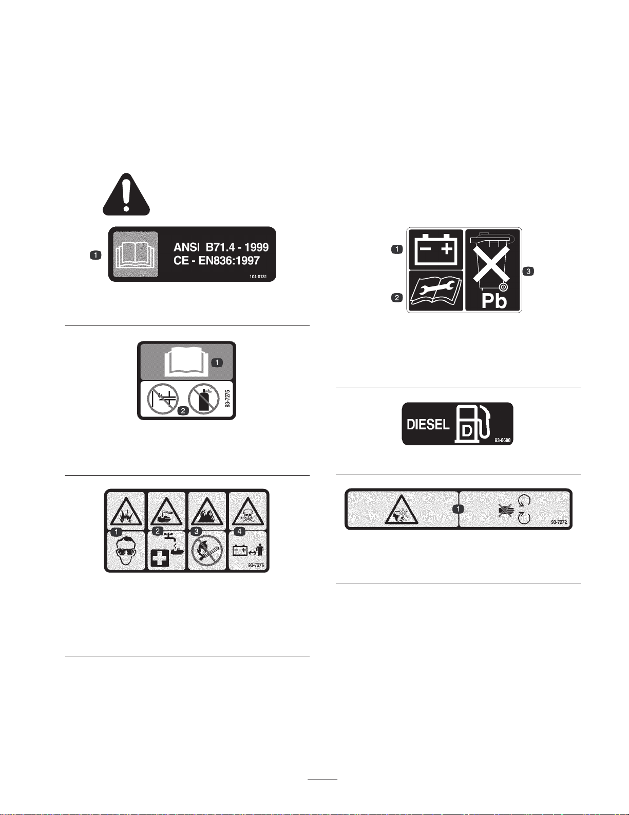
Safety and Instruction Decals
Safety decals and instructions are easily visible to the operator and are located near any area
of potential danger. Replace any decal that is damaged or lost.
104-0131
1. Read the
Operator’s Manual.
Whole Body
This unit does not exceed a vibration level of 0.5 m/s2 at
the posterior based on measurements of identical machines
per ISO 2631 procedures.
93-6668
1. Battery
2. Read the instructions
before servicing or
performing maintenance.
3. Contains lead; do not
discard.
1. Read the operator’s
manual.
1. Explosion hazard—wear
eye protection.
2. Caustic liquid/chemical
burn hazard—to perform
first aid, flush with water.
93-7275
2. Do not use starting aids.
93-6680
93-7272
1. Cutting/dismemberment hazard, fan—stay away from moving
parts.
93-7276
3. Fire hazard—No fire,
open flames, or smoking.
4. Poison hazard—keep
children a safe distance
from the battery.
7
Page 8
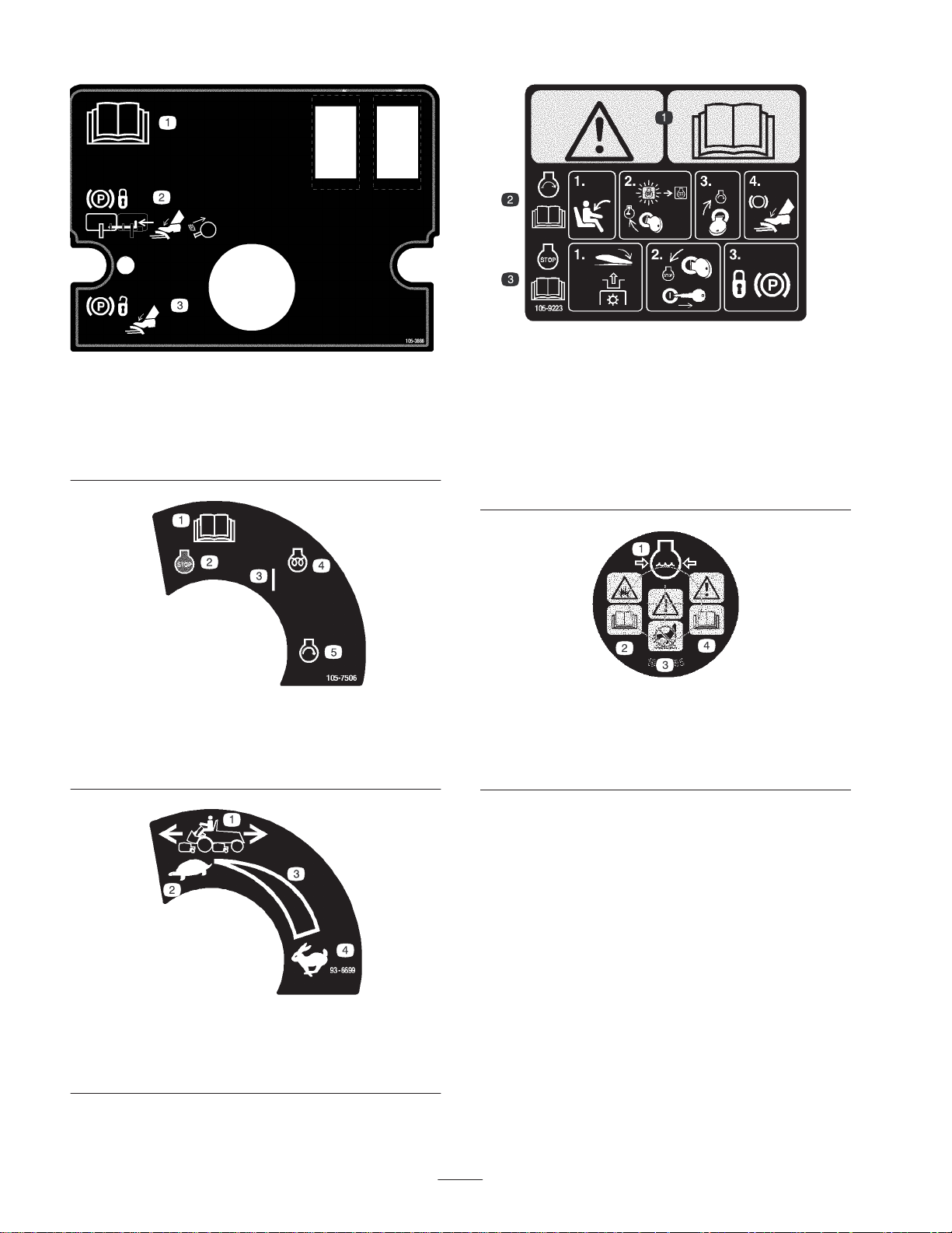
105-3888
1. Read the
2. To lock the parking brake, secure the brake pedals with the
locking pin, press the brake pedals, and pull out the the parking
brake knob.
3. To unlock the parking brake, press the brake pedal.
Operator’s Manual.
105-9223
(Affix over part no. 105–3890 for CE)
1. Warning—read the
2. To start the engine (read the
operator’s position, turn the ignition key to the Engine–run
position until the Engine–preheat light turns off, turn the ignition
key to the Engine–start position, and press the brake pedal.
3. To stop the engine (read the
the PTO, turn the ignition key to the Engine–stop position,
remove the key, and lock the parking brake.
Operator’s Manual.
Operator’s Manual
Operator’s Manual
), sit in the
), disengage
1. Read the
Manual
2. Engine—stop
1. Machine speed
2. Slow
Operator’s
105-7506
3. On
4. Engine—preheat
5. Engine—start
93-6699
3. Continuous variable
4. Fast
setting
1. Engine coolant under
pressure
2. Explosion hazard—read
Operator’s Manual.
the
106-6755
3. Warning—do not touch
the hot surface.
4. Warning—read the
Operator’s Manual.
8
Page 9
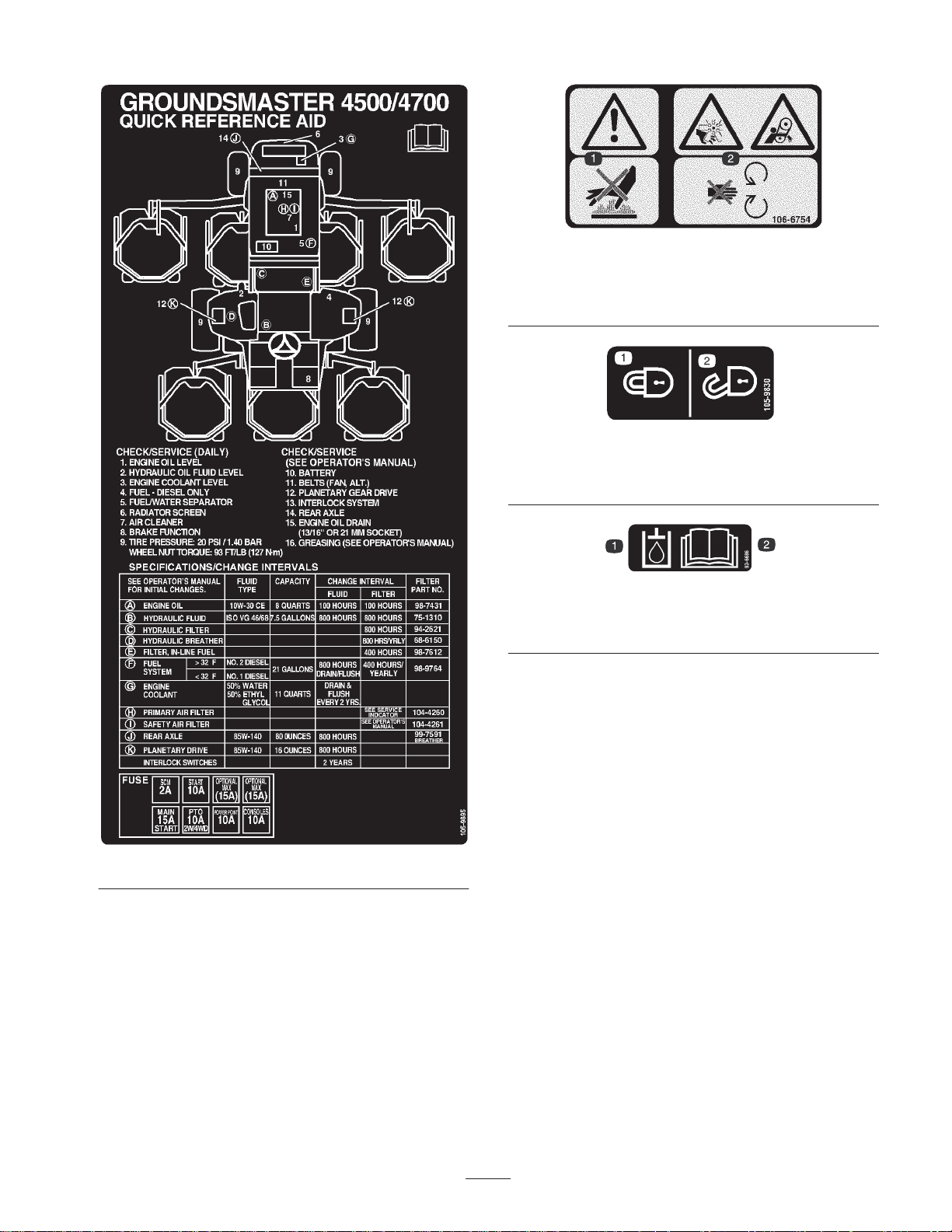
106-6754
1. Warning—do not touch the hot surface.
2. Cutting/dismemberment hazard, fan and entanglement hazard,
belt—stay away from moving parts
105-9830
(Affix for CE)
1. Lock 2. Unlock
93-6686
1. Hydraulic oil 2. Read the
Manual.
Operator’s
105-9895
9
Page 10
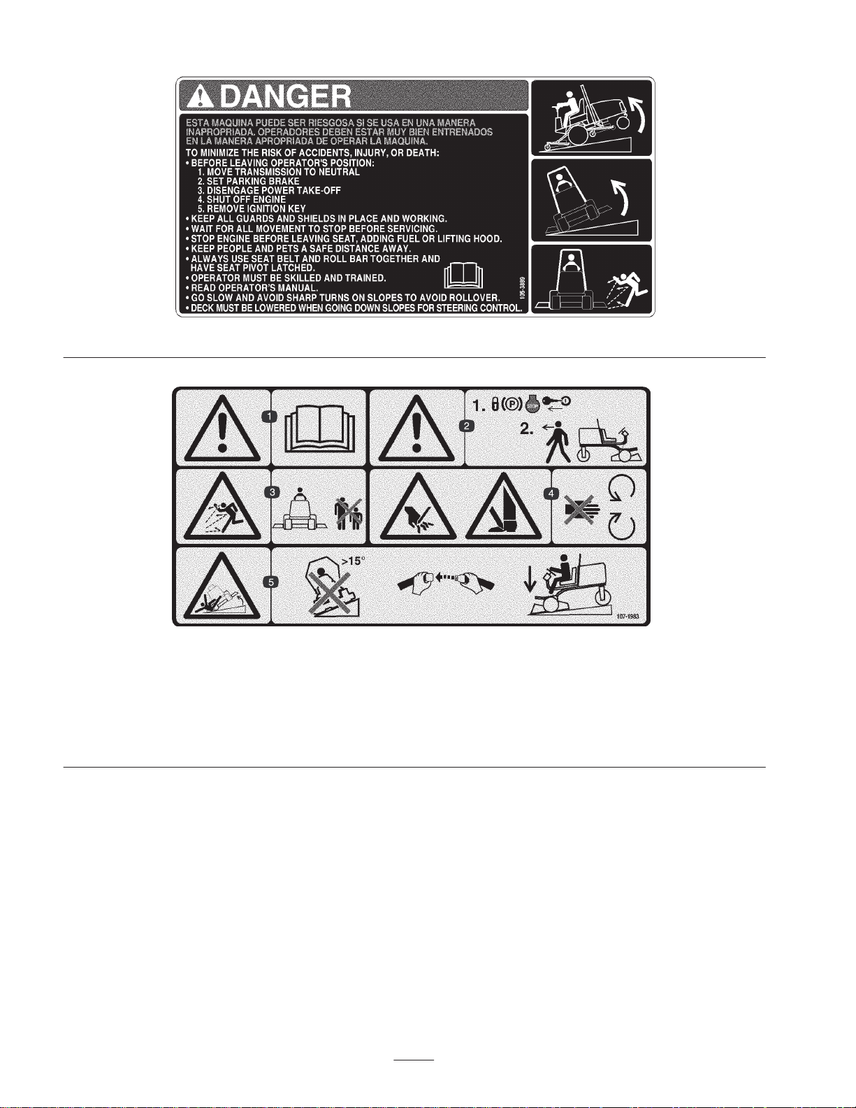
1. Warning—read the
Operator’s Manual.
2. Warning—lock the parking
brake, stop the engine, and
remove the ignition key
before leaving the machine.
105–3889
107-1983
(Affix over part no. 105–3889 for CE)
3. Thrown object hazard—keep
bystanders a safe distance
from the machine.
4. Cutting hazard of hand or
foot—stay away from
moving parts.
5. Tipping hazard—do not drive
the machine on a slope
greater than 15 degrees,
wear the seat belt, and lower
the cutting unit when driving
down slopes.
10
Page 11

1. Lower the cutting unit(s).
2. Raise the cutting unit(s).
3. Right cutting unit
(GM 4700–D only)
1. Input
2. Backlap
3. High temp
4. Center cutting units
5. Left cutting unit
(GM 4700–D only)
6. Fast
4. In seat
5. PTO switch
6. Park brake off
105-3890
7. Continuous variable setting
8. Slow
9. Engage
10. Disengage
105-8507
7. Neutral
8. Output
9. PTO
11. Power Take-off (PTO)
12. High
13. Low
14. Transmission
10. Start
11. ETR
12. Power
11
Page 12

Specifications
Traction Unit Specifications
Kubota, four-cycle, four cylinder, 122 in.3 displacement, water-cooled turbo diesel
Engine
Cooling system Capacity is 2-3/4 gallons (10.4 l) of 50/50 mixture of ethylene glycol anti-freeze.
engine. Rated 58 hp @ 2600 RPM, 23:1 compression ratio. Low idle—1300 RPM,
high idle—2800 RPM. Oil capacity is 8 qt. (7.6 l) with filter.
Fuel system
Hydraulic system Reservoir capacity is 7.5 gallons (30 l). Two replaceable spin-on filter elements.
Traction system
Ground speed
Tires
Diagnostic system
Steering system Automotive type, full power
Brakes Internal multiple wet disc brakes
Electrical system
Interlock system
Electric fuel pump. Replaceable inline filter and spin-on fuel filter/water separator.
Capacity is 21 gallons (79.5 l) of #2 diesel fuel.
Servo-controlled hydrostatic system driving planetary gear reduction front wheel
drives. Foot pedal control of forward/reverse ground speed.
Rear drive axle coupled to hydrostatic transmission for full time 4-wheel drive when
in Mow position. A Roll Over Protective Structure (ROPS) and seat belt are
standard.
Mow: 0–7 MPH (0–11.3 km/h)
Transport: 0–13 MPH (0–21 km/h)
Front: 29x14.00–15, 6-ply, tubeless ultra–track tread
Rear: 20x12.00–10, 6-ply, tubeless multi track tread
Front and back tire pressure is 20 psi (138 kPa).
Test ports for traction system, cutting unit drive system, lift/counterbalance,
lift/relief, steering circuits, and charge pressure are located near individual
components.
12 volt, 110 minute reserve capacity (DIN) battery and 40 amp. alternator. Negative
ground.
Prevents engine from starting unless traction pedal is in neutral and PTO is
disengaged. If the operator leaves seat with PTO engaged, after one second the
PTO will disengage and the engine will stop. Engine will stop if machine comes out
of neutral with parking brake set.
Gauges and indicator
lights
Controls
Note: Specifications subject to change without notice.
Fuel gauge, engine coolant temperature gauge, hour meter, indicator lights for high
engine coolant temperature, low engine oil pressure, glow plugs and charging.
Steering wheel, ignition switch, PTO switch, throttle control, traction pedal,
mow/transport speed selector switch, brakes (for turning or traction assist), parking
brake pedal lock, and cutting unit lift/lower levers
12
Page 13

Measurements
Width of cut 109 in. (2.8 m)
Overall width
cutting units down
cutting units up (transport)
Overall length 145.8 in. (370 cm)
Height with ROPS 85 in. (216 cm)
Ground clearance 6 in. (15 cm)
Track Width
front
rear
Wheel base 67-1/2 in. (171 cm)
112.8 in. (286 cm)
88.25 in. (224 cm)
88.25 in. (224 cm)
55.5 in. (141 cm)
Weight (with cutting units and
no fluids)
4123 lb. (1400 kg)
Optional Equipment
27” Rotary Cutting Unit Model No. 30827
Deluxe Seat Kit (Seat suspension
not included)
Seat Suspension Kit Model No. 30395
Arm Rest Kit Model No. 30707
Mulching Baffle Kit
(one per cutting unit)
High Lift Parallel Sail Blade
(one per cutting unit)
Warning
Do not use the high lift blade with the mulching
baffle. The blade could break, resulting in personal
injury or death.
Model No. 30398
Model No. 30828
Part No. 105–4089
13
Page 14

Setup
Note: Determine the left and right sides of the machine from the normal operating position.
Loose Parts
Note: Use this chart as a checklist to ensure that all parts necessary for assembly have been received. Without these parts,
total setup cannot be completed. Some parts may have already been assembled at the factory.
Description
Seat belt
Capscrew 7/16–20 x 1”
Lock washer 7/16
Manual tube
R-clamp
Parts catalog
Pre-delivery inspection sheet
Operator’s manual
Engine manual
Operator Video
Registration card
Installing the Seat, Seat Belt,
and Manual Tube
The machine is shipped without the seat assembly. Deluxe
Seat Kit, Model No. 30398, and Seat Suspension Kit,
Model No. 30395, must be purchased and installed.
1. Mount the manual tube to the seat suspension with the 2
R-clamps included in loose parts.
Qty. Use
1
2
2
1
2
1
1
2
1
1
1
Installing the seat belt
Installing the manual tube
Read before operating the machine.
View before operating machine
Fill out and return to Toro
Greasing the Machine
Before the machine is operated, it must be greased to
ensure proper lubrication. Refer to Greasing the Bearings
and Bushings section in the Operator’s Manual. Failure to
properly grease the machine will result in premature failure
of critical parts.
2. Install the seat belt to each side of the seat with a bolt
and lock washer, supplied in loose parts.
Important Make sure that the seat switch is connected
to the seat switch connector on the harness.
3. Slide the seat completely forward and backward to
ensure proper operation and that seat switch wires and
connectors are not pinched or do no contact any moving
parts.
14
Page 15

Before Operating
Caution
If you leave the key in the ignition switch, someone
could accidently start the engine and seriously
injure you or other bystanders.
Remove the key from the ignition before you do
any maintenance.
Checking the Engine Oil
Check the oil level at the beginning of each day.
The crankcase capacity is 8 qt. (7.6 l) with the filter.
1. Park the machine on a level surface. Unlock the engine
cover latches.
2. Open the engine cover.
3. Remove the dipstick, wipe it clean, install the dipstick
into the tube, and pull it out again. The oil level should
be up to the FULL mark (Fig. 1).
1
Figure 2
1. Oil fill cap
5. The engine uses any high-quality detergent oil having
the American Petroleum Institute (API) “service
classification” CD, CE, CF, CF-4, or CG-4. Use the
following chart to select the proper viscosity grade for
the temperature expected.
10W-30
above 77°F (25°C)
32° to 77°F (0° to 25°C)
SAE 30
SAE 20
or
10W-40
10W-30
or
10W-40
1
Figure 1
1. Dipstick
4. If the oil is below the FULL mark, remove the fill cap
(Fig. 2) and add oil until the level reaches the FULL
mark. Do not overfill.
10W-30
below 32°F (0°C)
Note: When using different oil, drain all old oil from the
crankcase before adding new oil.
6. Install the oil fill cap and dipstick.
7. Close the engine cover and secure it with the latches.
SAE 10
or
10W-40
Checking the Cooling System
Check level of coolant at the beginning of each day.
Capacity of system is 2-3/4 gal. (10.4 l).
1. Carefully remove the radiator cap and expansion tank
cap (Fig. 3).
15
Page 16

Caution
If the engine has been running, the pressurized,
hot coolant can escape and cause burns.
• Do not open the radiator cap when the engine is
running.
• Use a rag when opening the radiator cap, and
open the cap slowly to allow steam to escape.
2. Check the coolant level in the radiator. The radiator
should be filled to the top of the filler neck and the
expansion tank filled to the FULL mark.
1
Figure 3
1. Expansion tank
3. If the coolant is low, add a 50/50 mixture of water and
ethylene glycol anti-freeze. Do not use water only or
alcohol/methanol base coolants.
4. Install the radiator cap and expansion tank cap.
1
Figure 4
1. Fuel tank cap
2. Fill the tank to about 1 inch (25 mm) below the top of
the tank, not the filler neck, with No. 2 diesel fuel. Then
install the cap.
Danger
Under certain conditions, diesel fuel and fuel
vapors are highly flammable and explosive. A fire
or explosion from fuel can burn you and others
and can cause property damage.
• Use a funnel and fill the fuel tank outdoors, in
an open area, when the engine is off and is cold.
Wipe up any fuel that spills.
• Do not fill the fuel tank completely full. Add fuel
to the fuel tank until the level is 1/4 to 1/2 in. (6
to 13 mm) below the bottom of the filler neck.
This empty space in the tank allows the fuel to
expand.
• Never smoke when handling fuel, and stay away
from an open flame or where fuel fumes may be
ignited by a spark.
• Store fuel in a clean, safety-approved container
and keep the cap in place.
Filling the Fuel Tank
The capacity of the fuel tank is 21 gallons (79 l).
1. Remove the fuel tank cap (Fig. 4).
16
Page 17

Checking the Hydraulic Fluid
The machines reservoir is filled at the factory with
approximately 7.5 gallons of high quality hydraulic fluid.
Check the level of hydraulic fluid before the engine is
first started and daily thereafter. Appropriate hydraulic
oils are listed below.
The following list is not assumed to be all–inclusive.
Hydraulic fluids produced by other manufacturers may be
used if they cross find a cross reference equivalent to the
products listed. Toro will not assume responsibility for
damage caused by improper substitutions, so use only
products from reputable manufacturers who will stand
behind their recommendation.
Multigrade Hydraulic Fluid – ISO VG 46
Mobil. Contact your local Toro Distributor for details. This
oil is available in 5 gallon (19 l) containers from your Toro
Distributor, order part no. 100–7674.
1. Position the machine on a level surface, lower the
cutting units, stop the engine, and remove the key.
2. Clean the area around the filler neck and cap of the
hydraulic tank (Fig. 5). Remove the cap from the filler
neck.
Normal Climate: 0 (–18C) to 110F (43C)
Mobil DTE 15M
Amoco Rykon Premium ISO 46
Chevron Rykon Premium Oil ISO 46
Conoco Hydroclear AW MV46
Exxon Univis N46
Pennzoil AWX MV46
Shell Tellus T 46
Texaco Rando HDZ 46
Important The ISO VG 46 Multigrade fluid has been
found to offer optimal performance in a wide range of
temperature conditions. For operation in consistently high
ambient temperatures, 65F (18C) to 120F (49C), ISO
VG 68 hydraulic fluid may offer improved performance.
Note: Many hydraulic fluids are almost colorless, making it
difficult to spot leaks. A red dye additive for the hydraulic
system oil is available in 2/3 oz. (20 ml) bottles. One bottle
is sufficient for 4–6 gal (15–22 1) of hydraulic oil. Order
part no. 44–2500 from your authorized Toro distributor.
Not recommended for biodegradable fluid (use food
coloring).
Biodegradable Hydraulic Fluid – Mobil 22411
Important Mobil EAL 224H is the only biodegradable
oil tested and approved by Toro. Contamination by
mineral–based hydraulic fluids will change the
biodegradability and toxicity of this oil. When changing
from standard fluid to the biodegradable type, be certain to
follow the approved flushing procedure published by
1
Figure 5
1. Hydraulic tank cap
3. Remove the dipstick from the filler neck and wipe it
with a clean rag. Insert the dipstick into the filler neck;
then remove it and check the fluid level. The fluid level
should be between the two marks on the dipstick.
4. If the level is low, add the appropriate fluid to raise the
level to the upper mark.
5. Install the dipstick and cap onto the filler neck.
Checking the Planetary Gear
Drive Oil
Check the oil level after every 400 hours of operation or if
external leakage is noted. Use high quality SAE
85W-140 wt. gear lube as a replacement.
The capacity of the system is approximately 16 oz. (0.5 l).
1. With the machine on a level surface, position the wheel
so that the check/drain plug (Fig. 6) is at either the 2 or
10 o’clock position.
17
Page 18

Check Tire Pressure
1
Figure 6
1. Check/drain plug
2. Remove the plug on the planetary (Fig. 6). Oil should
be at the bottom of the check plug hole.
3. Add gear oil to the hole in the planetary, if necessary, to
bring the oil up to the proper level. Install the plug.
4. Repeat steps 1–3 on the opposite gear assembly.
Checking the Rear Axle
The tires are over-inflated for shipping. Therefore, release
some of the air to reduce the pressure. The correct air
pressure in the tires is 20 psi (138 kPa).
Important Maintain the recommended pressure in all
tires to ensure a good quality-of-cut and proper machine
performance. Do not under-inflate.
Checking the Torque of the
Wheel Nuts
Warning
Failure to maintain proper torque of the wheel
nuts could result in failure or loss of wheel and
may result in personal injury.
Torque the front and rear wheel nuts to
85–100 ft.-lb. (115–136 Nm) after 1–4 hours of
operation and again after 10 hours of operation.
Torque every 200 hours thereafter.
Note: Front wheel nuts are 1/2–20 UNF. Rear wheel nuts
are M12 x 1.6–6H (Metric).
Lubricant
The rear axle is shipped from the factory filled with SAE
85W-140 wt. gear lube. Check the oil level before the
engine is first started and every 400 hours thereafter. The
capacity is 80 oz. (2.4 l). Visually inspect for leaks daily.
1. Position the machine on a level surface.
2. Remove a check plug from one end of the axle (Fig. 7)
and make sure that the lubricant is up to the bottom of
the hole. If the level is low, remove the fill plug (Fig. 7)
and add enough lubricant to bring the level up to the
bottom of the check plug holes.
2
1
Figure 7
1. Check plug 2. Fill plug
18
Page 19

Operation
Note: Determine the left and right sides of the machine
from the normal operating position.
Forward Speed Control
Preset the forward speed control (Fig. 8) to limit the
amount the traction pedal can be depressed in the forward
direction to maintain a constant mowing speed.
Caution
This machine produces sound levels in excess of
85 dBA at the operators ear and can cause hearing
loss through extended periods of exposure.
Wear hearing protection when operating this
machine.
Controls
Traction Pedal
The traction pedal (Fig. 8) controls forward and reverse
operation. Depress the top of the pedal to move forward
and the bottom to move backward. Ground speed depends
on how far the pedal is depressed. For no load, maximum
ground speed, fully depress the pedal while the throttle is in
Fast.
6
7
4
5
2
Key Switch
The key switch (Fig. 8) has three positions: Off,
On/Preheat, and Start.
Engine Oil Pressure Warning Light
The light (Fig. 8) illuminates when the engine oil pressure
is dangerously low.
Charge Indicator
The charge indicator (Fig. 8) illuminates when the system
charging circuit malfunctions.
Engine Coolant Temperature Warning
Light
The light (Fig. 8) illuminates and the engine shuts down
when coolant reaches an excessively high temperature.
Glow Plug Indicator Light
When lit, the glow plug indicator light (Fig. 8) indicates
that the glow plugs are on.
1
3
Figure 8
1. Traction pedal
2. Forward speed control
3. Key switch
4. Engine oil pressure
warning light
To stop, reduce your foot pressure on the traction pedal and
allow it to return to the center position.
5. Charge indicator
6. Engine coolant
temperature warning light
7. Glow plug indicator light
Speed Limiter Screws
Adjust the screw(s) (Fig. 9) to limit the amount the traction
pedal can be depressed in the forward or reverse direction
to limit speed.
Important The speed limiter screw must stop the
traction pedal before the pump reaches full stroke or
damage to the pump may occur.
1
2
Figure 9
1. Forward speed limiter
screw
2. Reverse speed limiter
screw
19
Page 20

Brake Pedals
Engine Temperature Gauge
Two foot pedals (Fig. 10) operate individual wheel brakes
for turning assistance, parking, and to aid in obtaining
better side hill traction. A latch connects the pedals for
parking brake operation and transport.
Pedal Locking Latch
The pedal locking latch (Fig. 10) connects the pedals
together to engage the parking brake.
1
2
Figure 10
1. Brake pedals
2. Pedal locking latch
3
3. Parking brake latch
This gauge (Fig. 11) indicates the engine coolant
temperature.
PTO Switch
The PTO switch (Fig. 11) has two positions: On (engage)
and Off (disengage). Push the PTO switch forward to the
On position to start the implement or cutting unit blades.
Push the switch backward to the Off position to stop
implement operation.
Hi-Lo Speed Control
The switch (Fig. 11) allows the speed range to increase for
transport of the machine. Cutting decks will not operate in
high range.
2
1
3
4
7
5
Parking Brake Latch
A knob on the left side of the console actuates the parking
brake lock (Fig. 10). To engage the parking brake, connect
the pedals with the locking latch, push down on both
pedals, and pull the parking brake latch out. To release the
parking brake, depress both pedals until the parking brake
latch retracts.
Throttle Control
Move the control (Fig. 11) forward to increase the engine
speed and rearward to decrease the speed.
Lift Lever
The lever (Fig. 11) raises and lowers the cutting units.
Hour Meter
The hour meter (Fig. 11) shows the total hours that the
machine has been operated.
6
Figure 11
1. Throttle control
2. Lift lever
3. Hour meter
4. Engine temperature
gauge
5. PTO switch
6. Hi–Lo speed control
7. Power point
Power Point
The power point (Fig. 11) is used to power optional 12 volt
electrical accessories.
Fuel Gauge
The fuel gauge (Fig. 12) indicates the level of fuel in the
tank.
20
Page 21

2. Move the throttle control to the low idle position.
3. Turn the ignition key to the Run position. The glow
indicator will light.
4. When the glow indicator dims, turn the ignition key to
the Start position. Release the key immediately when
the engine starts and allow it to return to the Run
1
position. Move the throttle control to the desired
position.
Figure 12
1. Fuel gauge
Cutting Unit Lift Latch (CE)
The cutting unit lift latch (Fig. 13) locks the center five
cutting unit lift levers when the cutting units are in the
raised position.
1
Important Do not run the starter motor more than 15
seconds at a time or premature starter failure may result. If
the engine fails to start after 15 seconds, turn the key to the
Off position, recheck the controls and procedures, wait 15
additional seconds, and repeat the starting procedure.
When the temperature is less than 20°F (–7°C), the starter
motor can be run for 30 seconds on then 60 seconds off for
2 attempts.
5. When the engine is started for the first time, or after an
overhaul of the engine, transmission, or axle, operate
the machine in forward and reverse for one or two
minutes. Also operate the lift lever and PTO lever to
ensure proper operation of all parts. Turn the steering
wheel to the left and right to check steering response.
Then shut the engine off and check for oil leaks, loose
parts, and any other noticeable difficulties.
Caution
Shut the engine off and wait for all moving parts to
stop before checking for oil leaks, loose parts, and
other malfunctions.
Figure 13
1. Cutting unit lift latch
Starting and Stopping the
Engine
Important The fuel system must be bled if any of the
following situations have occurred:
• The engine has ceased running due to lack of fuel.
• Maintenance has been performed upon the fuel system
components.
Refer to Bleeding the Fuel System, page 21.
1. Remove your foot from the traction pedal and ensure
that it is in neutral. Ensure that the parking brake is set.
6. To stop the engine, move the throttle control backward
to the Slow position, move the PTO lever to the Off
position, set the parking brake, and rotate the ignition
key to Off. Remove the key from the switch to prevent
accidental starting.
Important Allow engine to idle for 5 minutes before
shutting it off after a full load operation. This allows the
turbo charger to cool down before shutting the engine off.
Failure to do so may lead to turbo–charger trouble.
Note: Lower cutting units to the ground whenever machine
is parked. This relieves the hydraulic load from the system,
prevents wear on system parts and also prevents accidental
lowering of the cutting units.
Bleeding the Fuel System
1. Park the machine on a level surface. Make sure that the
fuel tank is at least half full.
2. Unlatch and raise the hood.
21
Page 22

Danger
Under certain conditions, diesel fuel and fuel
vapors are highly flammable and explosive. A fire
or explosion from fuel can burn you and others
and can cause property damage.
• Use a funnel and fill the fuel tank outdoors, in
an open area, when the engine is off and is cold.
Wipe up any fuel that spills.
• Do not fill the fuel tank completely full. Add fuel
to the fuel tank until the level is 1/4 to 1/2 in. (6
to 13 mm) below the bottom of the filler neck.
This empty space in the tank allows the fuel to
expand.
• Never smoke when handling fuel, and stay away
from an open flame or where fuel fumes may be
ignited by a spark.
• Store fuel in a clean, safety-approved container
and keep the cap in place.
3. Open the air bleed screw on the fuel injection pump
(Fig. 14).
4. Turn the key in the ignition switch to the On position.
The electric fuel pump will begin operation, thereby
forcing air out around the air bleed screw. Leave the key
in the On position for 15 seconds. Air and fuel will be
internally drained back to fuel tank. Tighten the screw
and turn the key to Off.
Checking the Interlock
Switches
Caution
If safety interlock switches are disconnected or
damaged the machine could operate unexpectedly
causing personal injury.
• Do not tamper with the interlock switches.
• Check the operation of the interlock switches
daily and replace any damaged switches before
operating the machine.
• Replace switches every two years or 1500 hours,
whichever occurs first, regardless of whether
they are operating properly or not.
The machine has interlock switches in the electrical system.
These switches are designed to stop the engine when
operator gets off of the seat when the traction pedal is
depressed. However, the operator may get off of the seat
while the engine is running and the traction pedal is in
neutral. Although the engine will continue to run if the PTO
lever is disengaged and the traction pedal is released, it is
strongly recommended that the engine be stopped before
rising from the seat.
To check the operation of the interlock switches, perform
the following procedure:
1. Drive the machine slowly to a large, relatively open
area. Lower the cutting unit, stop the engine, and apply
the parking brake.
1
Figure 14
1. Fuel injection pump bleed screw
Note: Normally the engine should start after the above
bleeding procedures are followed. However, if the engine
does not start, air may be trapped between the injection
pump and injectors; refer to Bleeding Air from the
Injectors, page 35.
2. Sit on the seat and depress the traction pedal. Try to
start the engine. The engine should not crank. If the
engine cranks, there is a malfunction in the interlock
system that should be corrected before beginning
operation.
3. Sit on the seat and start the engine. Rise from the seat
and move the PTO lever to On. The PTO should not
engage. If the PTO engages, there is a malfunction in
the interlock system that should be corrected before
beginning operation.
4. Sit on the seat, engage the parking brake and start the
engine. Move the traction pedal out of the neutral
position. The engine should kill. If the engine does not
kill, there is a malfunction in the interlock system that
should be corrected before beginning operation.
22
Page 23

Pushing or Towing the Machine
Tie Downs
In an emergency, the machine can be moved forward by
actuating the bypass valve in the variable displacement
hydraulic pump and pushing or towing the machine. Do not
push or tow the machine for more than 1/4 mile
(0.4 km).
Important Do not push or tow the machine faster than
2–3 MPH (3–4.8 km/h) because internal transmission
damage may occur. The bypass valve must be open
whenever the machine is pushed or towed.
Important If the machine must to be pushed or towed
in reverse, the check valve in the four-wheel drive manifold
must also be bypassed. To bypass the check valve, connect
a hose assembly (Hose Part No. 95-8843, Coupler Fitting
No. 95-0985 [Qty. 2], and Hydraulic Fitting No. 340-77
[Qty. 2]) to the reverse traction pressure test port and the
reverse four-wheel drive pressure port.
1. Open hood and remove the center shroud
2. Rotate the valve 90° (1/4 turn) in either direction to
open and allow oil to bypass internally. Because fluid is
bypassed, the machine can be slowly moved without
damaging the transmission. Note the position of the
valve when opening or closing.
1
• On each side of the frame under the front steps
• The rear bumper
Operating Characteristics
Practice driving the machine because it has a hydrostatic
transmission and its characteristics are different than many
turf maintenance machines. Some points to consider when
operating the traction unit, cutting units, or other
implements are the transmission, engine speed, load on the
cutting blades or other implement components, and the
importance of the brakes.
To maintain enough power for the traction unit and
implement while operating, regulate the traction pedal to
keep the engine RPM high and somewhat constant. A good
rule to follow is to decrease the ground speed as the load on
the implement increases, and increase the ground speed as
the load decreases.
Therefore, allow the traction pedal to move backward as
the engine RPM decreases, and depress the pedal slowly as
the RPM increases. By comparison, when driving from one
work area to another, with no load and cutting unit raised,
have the throttle in the Fast position and depress the
traction pedal slowly but fully to attain maximum ground
speed.
Figure 15
1. Bypass valve
3. Close the bypass valve before starting the engine.
However, do not exceed 5–8 ft.-lb. (7–11 N⋅m) torque
to close the valve.
Jacking Points
• On the front of the machine on the frame on the inside
of each drive tire
• On the rear of the machine at the center of the axle
Another characteristic to consider is the operation of the
pedals that are connected to the brakes. The brakes can be
used to assist in turning the machine. However, use them
carefully, especially on soft or wet grass because the turf
may be torn accidentally. Another benefit of the brakes is to
maintain traction. For example, in some slope conditions,
the uphill wheel slips and loses traction. If this situation
occurs, depress the uphill turn pedal gradually and
intermittently until the uphill wheel stops slipping, thus,
increasing traction on the downhill wheel.
Use extra care when operating the machine on slopes.
Make sure that the seat latch is properly secured and the
seat belt is buckled. Drive slowly and avoid sharp turns on
slopes to prevent roll overs. For steering control, the cutting
cutting unit must be lowered when going downhill.
Warning
This product is designed to drive objects into the
ground where they lose energy quickly in grass
areas. However, careless operation, combined with
terrain angle, ricochets, or improperly positioned
safety guard can lead to thrown object injuries.
• When a person or pet appears suddenly in or
near the mowing area, stop mowing.
• Do not resume mowing until the area is cleared.
23
Page 24

Important Allow engine to idle for 5 minutes before
shutting it off after a full load operation. This allows the
turbo charger to cool down before shutting the engine off.
Failure to do so may lead to turbo–charger trouble.
Before stopping the engine, disengage all controls and
move the throttle to Slow. Moving the throttle to Slow
reduces high engine RPM, noise, and vibration. Turn the
key to Off to stop the engine.
High Lift Parallel Sail
The blade generally performs better in the higher heights of
cut (2 to 4 inch).
Attributes:
• More lift and higher discharge velocity.
• Sparse or limp turf is picked up significantly at
higher heights of cut.
Operating Tips
Mow When Grass is Dry
Mow either in the late morning to avoid the dew, which
causes grass clumping, or in late afternoon to avoid the
damage that can be caused by direct sunlight on the
sensitive, freshly mowed grass.
Select the Proper Height-of-Cut Setting to
Suit Conditions
Remove approximately 1 in. (25 mm) or no more than 1/3
of the grass blade when cutting. In exceptionally lush and
dense grass, you may have to raise the height-of-cut to the
next setting.
Mow at Proper Intervals
Under most normal conditions you will need to mow
approximately every 4–5 days. But remember, grass grows
at different rates at different times. This means that in order
to maintain the same height-of-cut, which is a good
practice, you will need to cut more frequently in early
spring; as the grass growth rate slows in mid summer, cut
only every 8–10 days. If you are unable to mow for an
extended period due to weather conditions or other reasons,
mow first with the height-of-cut at a high level; then mow
again 2–3 days later with a lower height setting.
Blade Selection
Standard Angled Sail
• Wet or sticky clippings are discharged more
efficiently reducing congestion in deck.
• Requires more horsepower to run.
• Tends to discharge further left and can tend to
windrow at lower heights of cut.
Warning
Do not use the high lift blade with the mulching
baffle. The blade could break, resulting in personal
injury or death.
Always Mow with Sharp Blades
A sharp blade cuts cleanly and without tearing or shredding
the grass blades like a dull blade. Tearing and shredding
causes the grass to turn brown at the edges which impairs
growth and increases susceptibility to diseases.
Transporting
Use the transport latches when transporting over long
distances, rough terrain, or when trailering.
After Operating
To ensure optimum performance, clean the underside of the
mower housing after each use. If residue is allowed to build
up in the mower housing, cutting performance will
decrease.
The blade generally performs best in lower heights of cut
(3/4 to 2–1/2 inch). The optional high lift parallel sail blade
performs better in the higher heights of cut (2 to 4 inch).
Attributes:
• Discharge remains more even at lower heights of
cut.
• Discharge has less tendency to throw left and thus a
cleaner look around bunkers and fairways.
• Lower power requirement at lower heights and
dense turf.
Note: Lower cutting units to the ground whenever machine
is parked. This relieves the hydraulic load from the system,
prevents wear on system parts and also prevents accidental
lowering of the cutting units.
Cutting Unit Pitch
We recommend a blade pitch of 5/16 in. (7.9 mm). A pitch
larger than 5/16 in. (7.9 mm) will result in less power
required, larger clippings, and a poorer quality of cut. A
pitch less than 5/16 in. (7.9 mm) will result in more power
required, smaller clippings and a better quality of cut.
24
Page 25

Grass Cutting: .75
o
is removed.
to 1.75 inch Height
of Cut
ion
Grass Cutting: 2.00
to 2.50 inch Height
Applicati
Pros
Cons
of Cut
Grass Cutting: 2.75
to 4.00 inch Height
of Cut
Leaf Mulching
Optional Equipment Configuration
Standard Angle Sail
Blade
Recommended in
most applications
Recommended for
thick or lush turf
May work well in
lush turf
Recommended for
use with the
mulching baffle
Even discharge at
lower height of cut
Cleaner look around
bunkers and fairways
Lower power
requirements
Does not lift the grass
well in high height of
cut applications
Wet or sticky grass
has a tendency to
build up in the chamber, leading to poor
quality of cut and
higher power requirement
High Lift Parallel
Sail Blade
DO NOT USE
WITH MULCHING
BAFFLE
May work well in
light or sparse turf
Recommended for
light or sparse turf
Recommended in
most applications
NOT ALLOWED
More lift and higher
discharge velocity
Sparse or limp turf is
picked up at high
height of cut
Wet or sticky
clippings are
discharged
efficiently
Requires more power
to run in some applications
Tends to windrow at
lower height of cut in
lush grass
DO NOT USE
WITH MULCHING
BAFFLE
Mulching Baffle Roller Scraper
Has been shown to
improve dispersion
and after cut perfor-
mance on northern
grasses that are cut at
least three times per
week and less than
1/3 of the grass blade
is removed.
DO NOT USE
WITH THE HIGH
LIFT PARALLEL
SAIL BLADE
Use with standard
angle sail blade only
May improve dispersion and appearance
in certain grass
cutting applications
Very good for leaf
mulching
Grass will build up in
the chamber if
attempting to remove
too much grass with
baffle in place
Can be used any time
that rollers build up
with grass or large
flat grass clumps of
grass are seen. The
scrapers may actually
increase clumping in
certain applications.
Reduces roller
buildup in certain
applications
25
Page 26

Standard Control Module
(SCM)
The Standard Control Module is a ”potted” electronic
device produced in a ”one size fits all” configuration. The
module uses solid state and mechanical components to
monitor and control standard electrical features required for
safe product operation.
The module monitors inputs including neutral, parking
brake, PTO, start, backlap, and high temperature. The
module energizes outputs including PTO, Starter, and ETR
(energize to run) solenoid.
The module is divided into inputs and outputs. Inputs and
outputs are identified by green LED indicators mounted on
the printed circuit board.
The start circuit input is energized by 12 VDC. All other
inputs are energized when the circuit is closed to ground.
Each input has a LED that is illuminated when the specific
circuit is energized. Use the input LED’s for switch and
input circuit troubleshooting.
Output circuits are energized by an appropriate set of input
conditions. The three outputs include PTO, ETR, and
START. Output LED’s monitor relay condition indicating
the presence of voltage at one of three specific output
terminals.
Output circuits do not determine output device integrity so
electrical troubleshooting includes output LED inspection
and conventional device and wire harness integrity testing.
Measure disconnected component impedance, impedance
through wire harness (disconnect at SCM), or by
temporarily ”test energizing” the specific component.
The SCM does not connect to an external computer or hand
held device, can not be re–programmed, and does not
record intermittent fault troubleshooting data.
The decal on the SCM only includes symbols. Three LED
output symbols are shown in the output box. All other
LED’s are inputs. The chart below identifies the symbols.
Backlap
Hi Temp
Inputs
Park Brake Off
Here are the logical troubleshooting steps for the SCM
device.
1. Determine the output fault you are trying to resolve
(PTO, START, or ETR).
2. Move key switch to ”ON” and ensure the red ”power”
LED is illuminated.
3. Move all input switches to ensure all LED’s change
state.
In Seat
PTO Switch
Neutral
PTO
Start
ETR
Start
Power
5. If specific output LED is illuminated without
appropriate output function, check output harness,
connections, and component. Repair as required.
6. If specific output LED is not illuminated, check both
fuses.
7. If specific output LED is not illuminated and inputs are
in appropriate condition, install new SCM and
determine if fault disappears.
Outputs
4. Position input devices at appropriate position to achieve
the appropriate output. Use the following logic chart to
determine the appropriate input condition.
26
Page 27

Each row (across) in the logic chart below identifies input and output requirements for each specific product function.
Product functions are listed in the left column. Symbols identify specific circuit condition including: energized to voltage,
closed to ground, and open to ground.
– Indicates a circuit closed to ground. – LED ON
O Indicates a circuit open to ground or de–energized – LED OFF
+ Indicates an energized circuit (clutch coil, solenoid, or start input) LED ON.
” ” A Blank indicates a circuit that is not involved with the logic.
To troubleshoot, turn on the key without starting the engine.
Identify the specific function that does not work and work
across the logic chart. Inspect the condition of each input
LED’s to ensure it matches the logic chart.
If the input LED’s are correct, check the output LED. If the
output LED is illuminated but the device is not energized,
measure available voltage at the output device, continuity
of the disconnected device, and potential voltage on the
ground circuit (floating ground). Repairs will vary
depending on your findings.
27
Page 28

Maintenance
Note: Determine the left and right sides of the machine from the normal operating position.
Recommended Maintenance Schedule
Maintenance Service
Interval
After first 10 hours
After first 50 hours
Every 50 hours
Every 100 hours
After first 200 hours
Every 200 hours
Every 400 hours
Maintenance Procedure
• Check the alternator belt tension.
• Torque the wheel lug nuts.
• Change the engine oil and filter.
• Check the engine RPM (at idle and full throttle).
• Lubricate all grease fittings.
• Inspect the air cleaner indicator.
• Check the battery level and cable connections.
• Change the engine oil and filter.
• Inspect the cooling system hoses.
• Check the alternator belt tension.
• Change the hydraulic oil.
• Change the hydraulic oil filters.
• Change the front planetary gear lube.
• Change the rear axle oil.
• Torque the wheel lug nuts.
• Service the spark arrestor.
• Service the air filter.
• Change the fuel filters (fuel/water and pre–filter)
• Inspect the fuel lines and connections.
• Check the engine RPM (at idle and full throttle)
• Check the rear axle oil level.
• Check the front planetary gear lube.
1
1
• Drain and clean the fuel tank.
• Change the hydraulic oil.
• Change the hydraulic oil filters.
Every 800 hours or
annually, whichever
occurs first
Every 1500 hours or 2
years, whichever occurs
first
1
If the indicator shows red
Important Refer to your engine operator’s manual and cutting unit operator’s manual for additional maintenance
procedures.
• Change the front planetary gear lube.
• Change the rear axle oil.
• Inspect, disassemble and install new seals in the cutting unit roller assemblies.
• Check the rear wheel toe-in.
• Check and adjust the valve clearance.
• Replace the hydraulic tank breather
• Replace moving hoses.
• Replace safety switches.
• Flush the cooling system and replace fluid.
28
Page 29

Daily Maintenance Checklist
Duplicate this page for routine use.
For the week of:
Maintenance Check Item
Check the safety interlock operation.
Check the brake operation.
Check the engine oil and fuel level.
Check the cooling system fluid level.
Drain the water/fuel separator.
Check the air filter restriction indicator.
Check the radiator, oil cooler, and
screen for debris.
Check unusual engine noises.
1
Check unusual operating noises.
Check the hydraulic system oil level.
Check hydraulic hoses for damage.
Check for fluid leaks.
Check the tire pressure.
Check the instrument operation.
Lubricate all grease fittings.
2
Mon. Tues. Wed. Thurs. Fri. Sat. Sun.
Touch-up damaged paint.
1
Check the glow plug and injector nozzles if hard starting, excess smoke, or rough running is noted.
2
immediately after every washing, regardless of the interval listed
Notation for Areas of Concern
Inspection performed by:
Item Date Information
1
2
3
4
5
6
7
8
9
10
11
12
29
Page 30

Service Interval Chart
Caution
If you leave the key in the ignition switch, someone could accidently start the engine and
seriously injure you or other bystanders.
Remove the key from the ignition before you do any maintenance.
30
Page 31

Greasing the Bearings and
Bushings
The machine has grease fittings that must be lubricated
regularly with No. 2 General Purpose Lithium Base Grease.
If the machine is operated under normal conditions,
lubricate all bearings and bushings after every 50 hours of
operation or immediately after every washing.
The grease fitting locations and quantities are:
Traction Unit
• Brake shaft pivot bearings (5) (Fig. 16)
• Rear axle pivot bushings (2) (Fig. 17)
• Steering cylinder ball joints (2) (Fig. 18)
• Tie rod ball joints (2) (Fig. 18)
• King pin bushings (2) (Fig. 18). The top fitting on the
king pin should only be lubricated annually
(2 pumps).
• Lift arm bushings (1 per deck) (Fig. 19)
• Lift cylinder bushings (2 per deck) (Fig. 19)
Figure 17
1
• Cutting unit spindle shaft bearings (1 per cutting unit)
(Fig. 20)
• Cutting unit carrier arm bushings (1 per cutting unit)
(Fig. 20)
Figure 16
Figure 18
1. Top fitting on king pin
31
Page 32

Figure 19
Hood Removal
To gain additional access to engine compartment, the hood
may be removed from traction unit.
1. Release hood latches (Fig. 21) and raise hood.
1
Figure 21
1. Hood latch
Figure 20
2. Unhook lanyard from hood pin, remove pin and slide
hood tubes rearward off guides (Fig. 22).
1
Figure 22
1. Hood pin
32
Page 33

Servicing the Air Cleaner
Check the air cleaner body for damage which could
possibly cause an air leak. Replace a damaged air cleaner
body.
Service the air cleaner filters when the air cleaner indicator
(Fig. 24) shows red or every 400 hours (more frequently in
extremely dusty or dirty conditions). Do not over-service
the air filter.
1
Figure 23
1. Air cleaner indicator
Be sure that the cover is sealing around the air cleaner
body.
1. Pull the latch outward and rotate the air cleaner cover
counterclockwise. Remove the cover from the body
(Fig. 24). Clean the inside of the air cleaner cover.
1
1
Figure 25
1. Air cleaner primary filter
3. Inspect the primary filter and discard it if it is damaged.
Do not wash or reuse a damaged filter.
Important Never attempt to clean the safety filter
(Fig. 26). Replace the safety filter with a new one after
every three primary filter services.
2
Figure 24
1. Air cleaner latch 2. Air cleaner cover
2. Gently slide the primary filter (Fig. 25) out of the air
cleaner body to reduce the amount of dust dislodged.
Avoid knocking the filter against the air cleaner body.
Do not remove the safety filter (Fig. 26).
1
Figure 26
1. Air cleaner safety filter
4. Cleaning the air filter:
A. Blow compressed air from the inside to the outside
of the dry filter element. To prevent damage to the
element, do not exceed 100 psi (689 kPa).
B. Keep the air hose nozzle at least 2 in. (51 mm) from
the filter and move the nozzle up and down while
rotating the filter element. Inspect the filter for holes
and tears by looking through it toward a bright light.
33
Page 34

5. Inspect the new filter for shipping damage. Check the
sealing end of the filter. Do not install a damaged filter.
6. Insert the new filter properly into the air cleaner body.
Make sure that the filter is sealed properly by applying
pressure to the outer rim of the filter when installing it.
Do not press on the flexible center of the filter.
7. Install the cover and secure the latch. Make sure that the
cover is positioned with the TOP side up.
8. Reset the indicator (Fig. 24) if it shows red.
Servicing the Engine Oil and
Filter
1
Change the oil and filter initially after the first 50 hours of
operation; thereafter change the oil and filter every 100
hours.
1. Remove the rear drain plug (Fig. 27) and let the oil flow
into a drain pan. When the oil stops, install the drain
plug.
1
Figure 27
1. Engine oil drain plug
2. Remove the oil filter (Fig. 28). Apply a light coat of
clean oil to the new filter seal before screwing it on. Do
not overtighten.
Figure 28
1. Engine oil filter
3. Add oil to the crankcase; refer to Checking the Engine
Oil, page 15.
Servicing the Fuel System
Danger
Under certain conditions, diesel fuel and fuel
vapors are highly flammable and explosive. A fire
or explosion from fuel can burn you and others
and can cause property damage.
• Use a funnel and fill the fuel tank outdoors, in
an open area, when the engine is off and is cold.
Wipe up any fuel that spills.
• Do not fill the fuel tank completely full. Add fuel
to the fuel tank until the level is 1/4 to 1/2 in. (6
to 13 mm) below the bottom of the filler neck.
This empty space in the tank allows the fuel to
expand.
• Never smoke when handling fuel, and stay away
from an open flame or where fuel fumes may be
ignited by a spark.
• Store fuel in a clean, safety-approved container
and keep the cap in place.
Fuel Tank
Drain and clean the fuel tank every 800 hours. Also, drain
and clean the tank if fuel system becomes contaminated or
if the machine will be stored for an extended period of
time. Use clean fuel to flush out the tank.
34
Page 35

Fuel Lines and Connections
Check the fuel lines and connections every 400 hours or
yearly, whichever comes first. Inspect them for
deterioration, damage, or loose connections.
Water Separator
Drain water or other contaminants from the water separator
(Fig. 29) daily.
1. Place a clean container under the fuel filter.
2. Loosen the drain plug on the bottom of the filter
canister (Fig. 29). Tighten the plug after draining.
2. Loosen the hose clamps at both ends of the filter and
pull the fuel lines off of the filter.
1
2
Figure 29
1. Water Separator 2. Drain plug
Replace filter canister after every 400 hours of
operation.
A. Clean the area where the filter canister mounts.
B. Remove the filter canister and clean the mounting
surface.
C. Lubricate the gasket on the filter canister with clean
oil.
1
1. Fuel pre-filter
3. Slide the hose clamps onto the ends of the fuel lines.
Push the fuel lines onto the fuel filter and secure them
with the hose clamps. Be sure that the arrow on the side
of the filter points toward the injection pump.
Figure 30
Bleeding Air from the Injectors
Note: This procedure should be used only if the fuel system
has been purged of air through normal priming procedures
and the engine will not start; refer to Bleeding the Fuel
System, page 21.
1. Loosen the pipe connection to the No. 1 injector nozzle
and holder assembly at the injection pump (Fig. 31).
D. Install the filter canister by hand until the gasket
contacts the mounting surface; then rotate it an
additional 1/2 turn.
Replacing the Fuel Pre-Filter
Replace the fuel pre-filter (Fig. 30), located between fuel
the tank and fuel pump, after every 400 operating hours or
yearly, whichever occurs first.
1. Clamp both fuel lines that connect to the fuel filter so
that fuel cannot drain when the lines are removed.
1
Figure 31
1. No. 1 injector nozzle
2. Move the throttle to the Fast position.
3. Turn the key in the ignition switch to the Start position
and watch the fuel flow around the connector. Turn the
key to the Off position when solid flow is observed.
4. Tighten the pipe connector securely.
35
Page 36

5. Repeat the procedure on the remaining nozzles.
Servicing the Engine Cooling
System
Remove debris from the engine area, oil cooler and radiator
daily. Clean them more frequently in dirty conditions.
1. Unlatch and swing open rear screen (Fig. 32). Clean the
screen thoroughly of all debris.
Note: To remove screen, lift off hinge pins.
1
2
1
Figure 34
1. Oil cooler 2. Radiator
Important Cleaning the radiator or oil cooler with
water will promote premature corrosion damage to
components and compact debris.
4. Pivot the oil cooler back into position. Secure it to the
frame with the latches, close the screen.
Figure 32
1. Rear screen latch
2. Rotate latches (Fig. 33) securing the oil cooler to the
frame.
1
Figure 33
1. Oil cooler latches
3. Pivot the oil cooler rearward. Clean both sides of the oil
cooler and radiator area (Fig. 34) thoroughly with
compressed air.
1
Servicing the Alternator Belt
Check the condition and tension of the belts (Fig. 35) after
every 100 operating hours.
1. Proper tension will allow 3/8 in. (10 mm) deflection
when a force of 10 lb. is applied on the belt midway
between the pulleys.
2. If the deflection is not 3/8 in. (10 mm), loosen the
alternator mounting bolts (Fig. 35). Increase or decrease
the alternator belt tension and tighten the bolts. Check
the deflection of the belt again to ensure that the tension
is correct.
2
Figure 35
1. Alternator 2. Mounting bolt
1
36
Page 37

Adjusting the Throttle
Adjust the throttle cable (Fig. 36) so that the governor lever
on the engine contacts the low and high speed set bolts
before the throttle lever contacts the slot in the seat base.
1
Figure 36
1. Throttle cable
Caution
Do not stand in line with the clean-out port.
Always wear safety glasses.
3. Stop the engine and replace the pipe plug.
Changing the Hydraulic Fluid
Change the hydraulic fluid after every 800 operating hours,
in normal conditions. If the fluid becomes contaminated,
contact your local Toro distributor because the system must
be flushed. Contaminated fluid looks milky or black when
compared to clean oil.
1. Turn the engine off and raise the hood.
2. Disconnect the case return line from the bottom of the
reservoir and let the hydraulic fluid flow into a large
drain pan. Connect the line when the hydraulic fluid
stops draining.
3. Fill the reservoir with approximately 7.5 gallons of
hydraulic fluid; refer to Checking the Hydraulic Fluid,
page 17.
Servicing the Spark Arrestor
Muffler
Every 200 hours operation, clear the muffler of carbon
buildup.
1. Remove the pipe plug from the clean-out port at the
lower side of the muffler.
Caution
The muffler may be hot and could cause injury.
Be careful while working around the muffler.
2. Start the engine. Plug the normal muffler exit with a
block of wood or metal plate so that the exhaust flow
will be forced out of the clean-out port. Continue to
block the exit until carbon deposits cease coming out of
the port.
Important Use only the hydraulic fluids specified.
Other fluids could cause system damage.
4. Install the reservoir cap. Start the engine and use all of
the hydraulic controls to distribute hydraulic fluid
throughout the system. Also check for leaks; then stop
the engine.
5. Check the fluid level and add enough to raise level the
level to the FULL mark on the dipstick. Do not overfill.
Replacing the Hydraulic Filters
Change the 2 hydraulic filters initially after the first 200
operating hours. Thereafter, change the filters after every
800 operating hours, in normal conditions.
Use Toro replacement filters Part No. 94-2621 for the rear
(cutting unit) of the machine and 75-1310 for the front
(charge) of the machine.
Important Use of any other filter may void the
warranty on some components.
1. Position the machine on a level surface, lower the
cutting units, stop the engine, engage the parking
brakes, and remove the ignition key.
37
Page 38

2. Clean the area around the filter mounting area. Place a
drain pan under the filter and remove the filter
(Fig. 37 & 38).
Checking the Hydraulic Lines
and Hoses
3. Lubricate the new filter gasket and fill the filter with
hydraulic fluid.
1
Figure 37
1. Hydraulic filter
Inspect the hydraulic lines and hoses daily for leaks, kinked
lines, loose mounting supports, wear, loose fittings, weather
deterioration, and chemical deterioration. Make all
necessary repairs before operating.
Warning
Hydraulic fluid escaping under pressure can
penetrate skin and cause injury.
• Make sure all hydraulic fluid hoses and lines are
in good condition and all hydraulic connections
and fittings are tight before applying pressure to
the hydraulic system.
• Keep your body and hands away from pin hole
leaks or nozzles that eject high pressure
hydraulic fluid.
• Use cardboard or paper to find hydraulic leaks.
• Safely relieve all pressure in the hydraulic
system before performing any work on the
hydraulic system.
• Seek immediate medical attention if fluid is
injected into skin.
1
Figure 38
1. Hydraulic filter
4. Ensure that the filter mounting area is clean. Screw the
filter on until the gasket contacts the mounting plate;
then tighten the filter an additional 1/2 turn.
5. Start the engine and let it run for about two minutes to
purge air from the system. Stop the engine and check
for leaks.
Hydraulic System Test Ports
The test ports are used to test the pressure in the hydraulic
circuits. Contact your local Toro distributor for assistance.
Test Port “A” (Fig. 39), located on rear of filter manifold,
under right hand frame rail. Used to measure the traction
system charge pressure.
1
Figure 39
1. Test port “A“ (Charge)
38
Page 39

Test Port “B” (Fig. 40), located on side of counter balance
manifold, under operators seat. Used to measure the
counter balance pressure applied to cutting units for
increased traction.
Test Port “C” (Fig. 40), located on front of 2 wheel drive/4
wheel drive manifold through front access panel on
operator platform. Used to measure the 4 wheel drive
pressure applied to the rear axle (reverse mode) and rear
axle dynamic braking.
Test Port “F” (Fig. 42), located on top of right hand deck
manifold. Used to measure cutting unit circuit pressure for
cutting units 5, 2 and 3.
Test Port “G” (Fig. 42), located on top of left hand deck
manifold. Used to measure cutting unit circuit pressure for
cutting units 1 and 4.
1
2
Figure 40
1. Test port “B“ (Counter
balance)
2. Test port “C“ ( Four wheel
drive)
Test Port “D” (Fig. 41), located on front of pump assembly,
under operators seat plate. Used to measure steering
pressure.
Test Port “E” (Fig. 41), located on front of pump assembly,
under operators seat plate. Used to measure lift circuit
pressure.
1
2
Figure 42
1. Test port “F“ (Decks) 2. Test port “G“ (Decks)
Test Port “H” (Fig. 43) located on rear traction circuit hard
line. Used to measure reverse traction pressure.
Test Port “I” (Fig. 43) located on front traction circuit hard
line. Used to measure forward traction pressure
2
1
1
2
Figure 41
1. Test port “D“ (Steering) 2. Test port “E“ (Lift circuit)
Figure 43
1. Test port “H“ (Reverse) 2. Test port “I“ (Forward)
39
Page 40

Adjusting Counterbalance
The counterbalance dial (Fig. 44) is used to adjust the
pressure in the counterbalance circuit. Recommended
counterbalance pressure is 620 psi. Rotate the adjusting dial
(Fig. 44) clockwise to increase the pressure or
counterclockwise to decrease the pressure.
2
1
Figure 44
1. Counterbalance dial 2. Traction assist valve
The traction assist valve (Fig. 44) is used to boost the
pressure in the counterbalance circuit. Recommended
traction assist counterbalance pressure is 700 psi when
traction pressure is above 1800 psi. Rotate the screw
(Fig. 44) clockwise to increase the pressure or
counterclockwise to decrease the pressure.
2
Adjust
Length
1
Figure 45
1. Pump rod 2. Pump control tube
5. After wheel rotation ceases, tighten jam nuts to secure
adjustment.
6. Stop the engine and release the right brake. Remove
jack stands and lower the machine to the shop floor.
Test drive the machine to make sure it does not creep.
2
Adjusting the Service Brakes
Adjust the service brakes when there is more than 1 in.
(25 mm) of “free travel” of the brake pedal, or when the
brakes do not work effectively. Free travel is the distance
the brake pedal moves before braking resistance is felt.
1
Important Traction unit must be at operating
temperature when adjusting hydraulic pressure.
Adjusting the Traction Drive for
Neutral
The machine must not creep when traction pedal is
released. If it does creep, an adjustment is required.
1. Park machine on a level surface, shut engine off,
position speed control into LOW range and lower
cutting units to the floor. Depress only the right brake
pedal and engage the parking brake.
2. Jack up left side of machine until left front tire is off the
shop floor. Support machine with jack stands to prevent
it from falling accidentally.
3. Start engine and allow run at low idle.
4. Adjust jam nuts on pump rod end to move pump control
tube forward to eliminate forward creep or rearward to
eliminate rearward creep (Fig. 45).
1. Disengage the locking latch from the brake pedals so
that both pedals work independently of each other.
2. To reduce free travel of the brake pedals, tighten the
brakes:
A. Loosen the front nut on the threaded end of the
brake cable (Fig. 46).
1
Figure 46
1. Brake cable
B. Tighten the rear nut to move the cable backward
until the brake pedals have 1/2 to 1 in. (13 to
25 mm) of free travel.
1
40
C. Tighten the front nuts after the brakes are adjusted
correctly.
Page 41

Changing the Planetary Gear
Drive Oil
Change the oil initially after first 200 hours of operation.
Thereafter change the oil every 800 hours, or yearly,
whichever occurs first. Use a high quality SAE 85W-140
wt. gear lube.
1. With the machine on a level surface, position the wheel
so that the check/drain plug (Fig. 47) is at the lowest
position (6 o’clock).
1
1
3
2
Figure 48
1. Brake housing
2. Drain plug
3. Check plug
Changing the Rear Axle
Lubricant
Change the oil initially after the first 200 hours of operation
and every 800 hours of operation thereafter.
Figure 47
1. Check/drain plug
2. Place a drain pan under the hub, remove the plug, and
allow the oil to drain.
3. Place another drain pan under the brake housing on the
other side of the wheel (Fig. 48).
4. Remove check/drain plugs from the brake housing and
allow the oil to drain.
5. When all of the oil has drained, install the bottom plug
in the brake housing.
6. Position the wheel so that the plug hole is at the ten or
two o’clock position on the planetary.
7. Slowly add approximately 16 oz. (0.5 l) of high quality
SAE 85W-140 wt. gear lube to the planetary fill hole (at
the ten or two o’clock position) until the level is up to
the bottom of the brake housing check hole. Install the
plug.
8. Repeat the procedure on the opposite planetary/brake
assembly.
1. Position the machine on a level surface.
2. Clean the area around the 3 drain plugs, 1 on each end
and 1 in the center (Fig. 49).
3. Remove the (3) oil level check plugs and main axle vent
cap to ease in draining of the oil.
4. Remove the drain plugs and allow the oil to drain into
the pans.
1
Figure 49
1. Drain plug location
5. Install the plugs.
6. Remove a check plug and fill axle with approximately
80 oz. of 85W–90 gear lube or until lubricant is up to
bottom of hole.
7. Install check plug.
41
Page 42

Checking the Rear Wheel
Charging and Connecting the
Toe-In
After every 800 operating hours or annually, check the rear
wheel toe-in.
1. Measure the center-to-center distance (at axle height) at
the front and rear of the steering tires. The front
measurement must be 1/8 in. (3 mm) less than the rear
measurement.
2. To adjust, remove the cotter pin and nut from either tie
rod ball joint. Remove tie rod ball joint from axle case
support.
3. Loosen the clamps at both ends of the tie rods.
1
Figure 50
1. Tie rod clamp
2. Tie rod ball joint
2
Battery
Warning
CALIFORNIA
Proposition 65 Warning
Battery posts, terminals, and related accessories
contain lead and lead compounds, chemicals
known to the State of California to cause cancer
and reproductive harm. Wash hands after
handling.
1. Unlatch and raise the hood.
2. Remove the battery strap and cover (Fig. 51).
2
1
4. Rotate the detached ball joint inward or outward one (1)
complete revolution. Tighten clamp at loose end of tie
rod.
5. Rotate the entire tie rod assembly the same direction
(inward or outward) one (1) complete revolution.
Tighten clamp at connected end of tie rod.
6. Install the ball joint in the axle case support and tighten
the nut finger tight. Measure toe–in.
7. Repeat procedure if necessary.
8. Tighten the nut and install a new cotter pin when the
adjustment is correct.
Figure 51
1. Battery cover 2. Battery strap
Danger
Battery electrolyte contains sulfuric acid which is a
deadly poison and causes severe burns.
• Do not drink electrolyte and avoid contact with
skin, eyes or clothing. Wear safety glasses to
shield your eyes and rubber gloves to protect
your hands.
• Fill the battery where clean water is always
available for flushing the skin.
3. Connect a 3 to 4 amp. battery charger to the battery
posts. Charge the battery at a rate of 3 to 4 amperes for
4 to 8 hours.
42
Page 43

Warning
Warning
Charging the battery produces gasses that can
explode.
Never smoke near the battery and keep sparks and
flames away from battery.
4. When the battery is charged, disconnect the charger
from the electrical outlet and battery posts.
5. Install the positive cable (red) to the positive (+)
terminal and the negative cable (black) to the negative
(—) terminal of the battery (Fig ). Secure cables to
posts with capscrews and nuts. Make sure that the
positive (+) terminal is all of the way onto the post and
the cable is positioned snug to the battery. The cable
must not contact the battery cover. Slide the rubber boot
over the positive terminal to prevent a possible short
from occurring.
12
Figure 52
1. Positive battery cable 2. Negative battery cable
Battery terminals or metal tools could short
against metal components causing sparks. Sparks
can cause the battery gasses to explode, resulting
in personal injury.
• When removing or installing the battery, do not
allow the battery terminals to touch any metal
parts of the machine.
• Do not allow metal tools to short between the
battery terminals and metal parts of the
machine.
6. Coat both battery connections with Grafo 112X
(skin-over) grease, Toro Part No. 505-47, petroleum
jelly, or light grease to prevent corrosion. Slide the
rubber boot over the positive terminal.
Warning
Incorrect battery cable routing could damage the
machine and cables causing sparks. Sparks can
cause the battery gasses to explode, resulting in
personal injury.
• Always disconnect the negative (black) battery
cable before disconnecting the positive (red)
cable.
• Always connect the positive (red) battery cable
before connecting the negative (black) cable.
7. Install the battery cover.
Warning
CALIFORNIA
Proposition 65 Warning
Battery posts, terminals, and related accessories
contain lead and lead compounds, chemicals
known to the State of California to cause cancer
and reproductive harm. Wash hands after
handling.
Battery Care
Important Before welding on the machine, disconnect
the terminal connector from the alternator to prevent
damage to the electrical system.
Note: Check the battery condition weekly or after every 50
hours of operation. Keep the terminals and the entire
battery case clean because a dirty battery will discharge
slowly. To clean the battery, remove it from the machine,
wash the entire case with a solution of baking soda and
water. Rinse with clear water. Coat the battery posts and
cable connectors with Grafo 112X (skin-over) grease (Toro
Part No. 505-47) or petroleum jelly to prevent corrosion.
43
Page 44

Fuses
There are 4 fuses in the electrical system. They are located
under the operators control panel (Fig. 53).
1. Rotate latches and remove control panel cover.
1
Figure 53
1. Fuse block
44
Page 45

Electrical Schematic
TEMP
I
G
L
S
GY
PK
(–)HR(+)
BK
P23–C9
ORBU/W
GN
W
GLOW
OVER TEMP.
LOW OIL PRESSURE
ALTERNATOR
CLUSTER GAUGE
BK
1, 4
D3
P23–C1
2 WD
GN
GN
1
PTO SWITCH
2
PK
1
2 WD / 4 WD
BK
BK
BN
GND
GLOW
THERMO
456
123
KUBOTA
CONTROLER
GLOW PLUG
LAMP
START
+ 12V
VIO
OR
PK
P23–B2
PK
P23–B1
2, 3, 5
FRONT PTO
FRONT PTO
GN
BK
R
W
P23–C5
P23–C6
P23–C7
P23–C4
5
3
2
4
1
6
MODULE
RAMP–UP
PK
F
878687a
CD1–C
30
85
CENTER PTO K2
GN
BU
DECK UP
(IN CENTER POSITION)
P23–B9
BU Y
POSITION POSITION
FRONT DECK FRONT DECK
BN
T
BU
364
5
OR
P23–A1
364
5
2
W
VIO
BK
T
BN
PK
R/BK
1–F
1–E
1–D
1–C
1–B
1–A
RUN
+12 V
PTO SW.
GROUND
PTO COIL
NOT USED
BK
BK
PK
P4–B
R/BK
(HOLD)
RUN SOLENOID
B
ALTERNATOR
IGN. SW. ”S”
NEUTRAL SW.
SEAT SW.
BACKLAP
IGN. SW. ”I”
START
PARKING BRAKE
F 7
P23–A5
R
HIGH TEMP SW.
2–B
BU/W
BU
P23–B6
2–E
2–D
2–C
OR
W/BK
P23–B4
OR
PARKING BRAKE (ON)
2 A
F 5
STOP –––– NONE
R
F 8
2–H
2–G
2–F
VIOGNGY
P23–B3
P23–B5
GY
GN
SEAT SWITCH
NEUTRAL SWITCH
BK
PK
10 AF 4
P23–D3
RUN STARTOFF
IGNITION SW
START ––– B+I+S
RUN –––– B+I+A; X+Y
P23–D2
X
SY
BA
I
F 1 15 A
STANDARD CONTROL MODULE
Y
IB
OR
A
10 A
F 6
P23–C8
P23–D5
T
W
Y
S
X
P23–D1
BU
POWER POINT
W
10 AF 3
10 A
F 2
R/BK
BU/W
BN
R/BK
GLOW RELAY
K4
8586
PK
87
P4–D
P4–G
P4–A
GY
TEMP SENDER
PK
GN
ENGINE OIL PRESSURE
P4–C
BU/W
OR
P5–A
ENGINE OVER TEMP.
R/BK
110 C
GLOW PLUGS (4)
FUEL PUMP
P4–F
BK
W
(PULL)
L
R
W
R
P23–C10
30
SP
R
FUSIBLE LINK
G
Start
B+
FL
FL
FL
P5–B
BK
ENGINE GROUND
ENGINE
BU
R
P23–B7
(+)(–)
BATTERY
FRAME GROUND
P4–E
P23–A3
BK
BU
P23–A2
45
Page 46

Hydraulic Schematic
.
COMP. CIR GPM PSI
FLOWS CALC. AT 2700 RPM AND .98 EFF
P1 1.02 11.7
P2 1.02 11.7
P3 0.58 6.6
P4 3.02 34.6
M1 1.16 2100
M2 1.16 2100
M3 1.16 2100
M4 1.16 2100
M5 1.16 2100
MF 2.01
MR 2.48
V1 6.1
PD3 1800
RV1 620
RV2 700
PR1 450
PRV1 3500
PRV2 3500
RV5 550
RV7 2200
COMP. BORE STROKE ROD
RV8 1100
C1 1.50 4.00 .625
C2 1.50 3.50 .625
C3 1.50 3.50 .625
C4 1.50 7.00 .625
C5 1.50 7.00 .625
CS 2.00 4.20 .625
RV2
TRACTION ASSIST
POWER DOWN AND
CONTROL MANIFOLD
TRACTION ASSIST
CONTROL MANIFOLD
RV7
RV
I
LIFT/LOWER
CONTROL VALVECONTROL VALVE
RV1
CHG
4
2
PD3
5
G
PP
CB
C4 C1 C5
.094
A
1500
PSI
O
G
B
PRIORITY FLOW
FILTER
REAR
11.9:1
FORWARD
MR
PD2
CV
3
11.96:1
MF
FRONT
MF
11.96:1
PSI
5000
P 4
P1
P2
P3
PROPORTIONALPROPORTIONAL
FLOW DIVIDER
M2
GAGE
T
5B
.052
B
PR1
8
P2
G
FILTRATION AND CHARGE CONTROL MANIFOLD
G
CD1
RV
VALVE
TOW
P2
5 PSI
180 PSI
CD2
P1
FILTER
40
PSI
T
OIL
COOLER
M1
5A
RV5
7
P1
CHG
FNT PORTS
5000
PSI
LH PORT
50 / 50
50 / 50
PSI
50
CHG M1
PD1
SV
2
C2 C3
4WD / 2WD CONTROL MANIFOLD
G
G
G
T
P
PB
PSI
1180
V1
R
L
CS
STEER CONTROL VALVE
T2
DECK CONTROL MANIFOLD
G2
T1
P1
G1
PRV2
LC1
RV8
M1
M2
M2
M3
M5
T1
T2
G2
P1
G1
PRV1
LC1
RV8
M1
M2
M1
M4
46
Page 47

Preparing for Seasonal Storage
Traction Unit
1. Thoroughly clean the traction unit, cutting units, and the
engine.
2. Check the tire pressure; refer to Checking the Tire
Pressure.
3. Check all fasteners for looseness; tighten as necessary.
4. Grease or oil all grease fittings and pivot points. Wipe
up any excess lubricant.
5. Lightly sand and use touch–up paint on painted areas
that are scratched, chipped, or rusted. Repair any dents
in the metal body.
6. Service the battery and cables as follows:
A. Remove the battery terminals from the battery posts.
Engine
1. Drain the engine oil from the oil pan and install the
drain plug.
2. Remove and discard the oil filter. Install a new oil filter.
3. Refill the oil pan with 8 qt. (7.6 l) of SAE 10W-30 CD,
CE, CF, CF-4, or CG-4 motor oil.
4. Start the engine and run it at idle speed for
approximately two minutes.
5. Stop the engine.
6. Flush the fuel tank with fresh, clean diesel fuel.
7. Secure all of the fuel system fittings.
8. Thoroughly clean and service the air cleaner assembly.
9. Seal the air cleaner inlet and the exhaust outlet with
weatherproof tape.
B. Clean the battery, terminals, and posts with a wire
brush and baking soda solution.
C. Coat the cable terminals and battery posts with
Grafo 112X skin-over grease (Toro Part No. 505-47)
or petroleum jelly to prevent corrosion.
D. Slowly recharge the battery every 60 days for 24
hours to prevent lead sulfation of the battery.
10.Check the anti freeze protection and add a 50/50
solution of water and ethylene glycol anti-freeze as
needed for the expected minimum temperature in your
area.
47
Page 48

The Toro General Commercial Products Warranty
A Two-Year Limited Warranty
Conditions and Products Covered
The Toro Company and its affiliate, Toro Warranty Company,
pursuant to an agreement between them, jointly warrant your Toro
Commercial Product (“Product”) to be free from defects in
materials or workmanship for two years or 1500 operational
hours*, whichever occurs first. Where a warrantable condition
exists, we will repair the Product at no cost to you including
diagnosis, labor, parts, and transportation. This warranty begins
on the date the Product is delivered to the original retail purchaser.
* Product equipped with hour meter
Instructions for Obtaining Warranty Service
You are responsible for notifying the Commercial Products
Distributor or Authorized Commercial Products Dealer from whom
you purchased the Product as soon as you believe a warrantable
condition exists.
If you need help locating a Commercial Products Distributor or
Authorized Dealer, or if you have questions regarding your
warranty rights or responsibilities, you may contact us at:
Toro Commercial Products Service Department
Toro Warranty Company
8111 Lyndale Avenue South
Bloomington, MN 55420-1196
952-888-8801 or 800-982-2740
E-mail: commercial.service@toro.com
Owner Responsibilities
As the Product owner, you are responsible for required maintenance and adjustments stated in your operator’s manual. Failure
to perform required maintenance and adjustments can be grounds
for disallowing a warranty claim.
Items and Conditions Not Covered
Not all product failures or malfunctions that occur during the
warranty period are defects in materials or workmanship. This
express warranty does not cover the following:
• Product failures which result from the use of non-Toro
replacement parts, or from installation and use of add-on,
modified, or unapproved accessories
• Product failures which result from failure to perform required
maintenance and/or adjustments
• Product failures which result from operating the Product in an
abusive, negligent or reckless manner
• Parts subject to consumption through use unless found to be
defective. Examples of parts which are consumed, or used up,
during normal Product operation include, but are not limited to,
blades, reels, bedknives, tines, spark plugs, castor wheels,
tires, filters, belts, etc.
• Failures caused by outside influence. Items considered to be
outside influence include, but are not limited to, weather,
storage practices, contamination, use of unapproved coolants,
lubricants, additives, or chemicals, etc.
• Normal “wear and tear” items. Normal “wear and tear”
includes, but is not limited to, damage to seats due to wear or
abrasion, worn painted surfaces, scratched decals or windows, etc.
Parts
Parts scheduled for replacement as required maintenance are
warranted for the period of time up to the scheduled replacement
time for that part.
Parts replaced under this warranty become the property of Toro.
Toro will make the final decision whether to repair any existing part
or assembly or replace it. Toro may use factory remanufactured
parts rather than new parts for some warranty repairs.
General Conditions
Repair by an Authorized Toro Distributor or Dealer is your sole
remedy under this warranty.
Neither The Toro Company nor Toro Warranty Company is
liable for indirect, incidental or consequential damages in
connection with the use of the Toro Products covered by this
warranty, including any cost or expense of providing substitute equipment or service during reasonable periods of
malfunction or non-use pending completion of repairs under
this warranty . Except for the Emissions warranty referenced
below, if applicable, there is no other express warranty. All
implied warranties of merchantability and fitness for use are
limited to the duration of this express warranty.
Some states d o n o t a l l o w exclusions of incidental or consequential
damages, or limitations on how long an implied warranty lasts, so
the above exclusions and limitations may not apply to you.
This warranty gives you specific legal rights, and you may also
have other rights which vary from state to state.
Note regarding engine warranty: The Emissions Control
System on your Product may be covered by a separate warranty
meeting requirements established by the U.S. Environmental
Protection Agency (EPA) and/or the California Air Resources
Board (CARB). The hour limitations set forth above do not apply to
the Emissions Control System Warranty. Refer to the Engine
Emission Control Warranty Statement printed in your operator’s
manual or contained in the engine manufacturer’s documentation
for details.
Countries Other than the United States or Canada
Customers who have purchased Toro products exported from the United States or Canada should contact their Toro Distributor (Dealer)
to obtain guarantee policies for your country , province, or state. If for any reason you are dissatisfied with your Distributor’s service or
have difficulty obtaining guarantee information, contact the Toro importer. If all other remedies fail, you may contact us at Toro Warranty
Company.
Part No. 374-0031 Rev. a
 Loading...