


FormNo.3424-443RevA
Groundsmaster
®
4300-DTraction
Unit
ModelNo.30864—SerialNo.403270001andUp
Registeratwww.T oro.com.
OriginalInstructions(EN)
*3424-443*A
ThisproductcomplieswithallrelevantEuropean
directives;fordetails,pleaseseetheseparateproduct
specicDeclarationofConformity(DOC)sheet.
ItisaviolationofCaliforniaPublicResourceCode
Section4442or4443touseoroperatetheengineon
anyforest-covered,brush-covered,orgrass-covered
landunlesstheengineisequippedwithaspark
arrester,asdenedinSection4442,maintainedin
effectiveworkingorderortheengineisconstructed,
equipped,andmaintainedforthepreventionofre.
WARNING
Wheneveryouneedservice,genuineToroparts,or
additionalinformation,contactanAuthorizedService
DealerorToroCustomerServiceandhavethemodel
andserialnumbersofyourproductready.Themodel
andserialnumbersareonaplatemountedonthe
leftsideoftheframeunderthefootrest.Writethe
numbersinthespaceprovided.
ModelNo.
SerialNo.
CALIFORNIA
Proposition65Warning
Dieselengineexhaustandsomeofits
constituentsareknowntotheStateof
Californiatocausecancer,birthdefects,
andotherreproductiveharm.
Batteryposts,terminals,andrelated
accessoriescontainleadandlead
compounds,chemicalsknownto
theStateofCaliforniatocause
cancerandreproductiveharm.Wash
handsafterhandling.
Useofthisproductmaycauseexposure
tochemicalsknowntotheStateof
Californiatocausecancer,birthdefects,
orotherreproductiveharm.
Important:Withyourmobiledevice,youcan
scantheQRcodeontheserialnumberdecal(if
equipped)toaccesswarranty,parts,andother
productinformation.
Thismanualidentiespotentialhazardsandhas
safetymessagesidentiedbythesafety-alertsymbol
(Figure1),whichsignalsahazardthatmaycause
seriousinjuryordeathifyoudonotfollowthe
recommendedprecautions.
g000502
Figure1
1.Safety-alertsymbol
Thismanualuses2wordstohighlightinformation.
Importantcallsattentiontospecialmechanical
informationandNoteemphasizesgeneralinformation
worthyofspecialattention.
Introduction
Thismachineisaride-on,rotary-bladelawnmower
intendedtobeusedbyprofessional,hiredoperators
incommercialapplications.Itisprimarilydesigned
forcuttinggrassonwell-maintainedlawnsinparks,
sportselds,andoncommercialgrounds.
Important:Tomaximizethesafety ,performance,
andproperoperationofthismachine,carefully
readandfullyunderstandthecontentsofthis
Operator’sManual.Failingtofollowthese
operatinginstructionsortoreceiveproper
trainingmayresultininjury.Formoreinformation
onsafeoperatingpractices,includingsafetytips
andtrainingmaterials,gotowww.Toro.com.
YoumaycontactT orodirectlyatwww.T oro.com
forproductsafetyandoperationtrainingmaterials,
accessoryinformation,helpndingadealer,orto
registeryourproduct.
©2018—TheToro®Company
8111LyndaleAvenueSouth
Bloomington,MN55420
Contactusatwww.Toro.com.
2
PrintedintheUSA
AllRightsReserved

Contents
Safety.......................................................................4
GeneralSafety...................................................4
SafetyandInstructionalDecals..........................4
Setup........................................................................9
1AdjustingtheControlArmPosition...................9
2RemovingtheShippingBlocksand
Pins.................................................................9
3AdjustingtheRollerScraper...........................10
4InstallingtheMulchingBafe...........................11
5PreparingtheMachine....................................11
ProductOverview...................................................12
Controls...........................................................12
Specications..................................................19
CuttingUnitSpecications................................20
Attachments/Accessories.................................20
BeforeOperation.................................................21
BeforeOperationSafety...................................21
FillingtheFuelTank..........................................21
CheckingtheEngine-OilLevel..........................23
CheckingtheCoolingSystem...........................23
CheckingtheHydraulicSystem........................23
DrainingtheWaterSeparator...........................23
CheckingtheTirePressure...............................23
CheckingtheT orqueoftheWheel-Lug
Nuts..............................................................23
AdjustingtheHeightofCut...............................24
CheckingtheSafety-InterlockSwitches............25
BurnishingtheBrakes.......................................25
SelectingaBlade..............................................25
UnderstandingtheDiagnosticLight..................26
ChangingtheCounterbalanceSettings............26
ChoosingAccessories......................................27
DuringOperation.................................................28
DuringOperationSafety...................................28
StartingtheEngine...........................................29
ShuttingOfftheEngine.....................................29
CuttingGrasswiththeMachine........................29
DieselParticulateFilterRegeneration...............30
OperatingTips.................................................42
AfterOperation....................................................43
AfterOperationSafety......................................43
IdentifyingtheTie-DownPoints........................43
HaulingtheMachine.........................................43
PushingorT owingtheMachine........................44
Maintenance...........................................................45
RecommendedMaintenanceSchedule(s)...........45
DailyMaintenanceChecklist.............................46
Pre-MaintenanceProcedures..............................47
MaintenanceSafety..........................................47
RaisingtheMachine.........................................47
Lubrication..........................................................48
GreasingtheBearingsandBushings................48
EngineMaintenance...........................................50
EngineSafety...................................................50
ServicingtheAirCleaner..................................50
ServicingtheEngineOil....................................51
ServicingtheDiesel-OxidationCatalyst
(DOC)andtheSootFilter..............................52
FuelSystemMaintenance...................................53
ServicingtheFuelFilter....................................53
ServicingtheFuelSystem................................53
ServicingtheWaterSeparator..........................54
ServicingtheFuel-PickupTube........................54
ElectricalSystemMaintenance...........................55
ElectricalSystemSafety...................................55
ServicingtheBattery.........................................55
LocatingtheFuses...........................................55
DriveSystemMaintenance..................................56
AdjustingtheTractionDriveforNeutral.............56
AdjustingtheRearWheelT oe-in.......................56
CoolingSystemMaintenance..............................57
CoolingSystemSafety.....................................57
CheckingtheCoolingSystem...........................57
RemovingDebrisfromtheCooling
System..........................................................57
BrakeMaintenance.............................................59
AdjustingtheParkingBrakes............................59
AdjustingtheParking-BrakeLatch....................59
BeltMaintenance................................................60
ServicingtheAlternatorBelt.............................60
HydraulicSystemMaintenance...........................60
HydraulicSystemSafety...................................60
CheckingtheHydraulic-FluidLevel...................60
ChangingtheHydraulicFluid............................62
ReplacingtheHydraulicFilters.........................62
CheckingtheHydraulicLinesand
Hoses............................................................63
TestingtheHydraulic-SystemPressure............63
HydraulicValveSolenoidFunctions..................63
CuttingUnitMaintenance.....................................64
SeparatingtheCuttingUnitfromtheTraction
Unit...............................................................64
MountingtheCuttingUnitstotheTraction
Unit...............................................................64
ServicingtheFrontRoller.................................64
BladeMaintenance..............................................65
BladeSafety.....................................................65
ServicingtheBladePlane.................................65
RemovingandInstallingaBlade.......................67
InspectingandSharpeningtheBlade................67
Storage...................................................................68
PreparingtheMachineforStorage...................68
StoringtheCuttingUnits...................................69
3

Safety
Thismachinehasbeendesignedinaccordancewith
ENISO5395:2013andANSIB71.4-2017.
GeneralSafety
Thisproductiscapableofamputatinghandsand
feetandofthrowingobjects.Alwaysfollowallsafety
instructionstoavoidseriouspersonalinjury.
Usingthisproductforpurposesotherthanitsintended
usecouldprovedangeroustoyouandbystanders.
•Readandunderstandthecontentsofthis
Operator’sManualbeforestartingtheengine.
•Useyourfullattentionwhileoperatingthe
machine.Donotengageinanyactivitythat
causesdistractions;otherwise,injuryorproperty
damagemayoccur.
•Donotputyourhandsorfeetnearmoving
componentsofthemachine.
•Donotoperatethemachinewithoutallguards
andothersafetyprotectivedevicesinplaceand
workingonthemachine.
•Keepclearofanydischargeopening.Keep
bystandersandpetsasafedistanceawayfrom
themachine.
•Keepchildrenoutoftheoperatingarea.Never
allowchildrentooperatethemachine.
•Stopthemachine,shutofftheengine,removethe
key,andwaitforallmovingpartstostopbefore
servicing,fueling,oruncloggingthemachine.
Improperlyusingormaintainingthismachinecan
resultininjury .T oreducethepotentialforinjury,
complywiththesesafetyinstructionsandalways
payattentiontothesafety-alertsymbol
meansCaution,Warning,orDanger—personalsafety
instruction.Failuretocomplywiththeseinstructions
mayresultinpersonalinjuryordeath.
Youcanndadditionalsafetyinformationwhere
neededthroughoutthisOperator’sManual.
,which
SafetyandInstructionalDecals
Safetydecalsandinstructionsareeasilyvisibletotheoperatorandarelocatednearanyarea
ofpotentialdanger.Replaceanydecalthatisdamagedormissing.
93-6681
1.Cutting/dismemberment—hazard,fan-stayawayfrom
movingparts.
93-6689
1.Warning—donotcarrypassengers.
decal93-6681
decal93-7818
93-7818
1.Warning—readtheOperator'sManualforinstructionson
torquingthebladebolt/nutto1 15to149N∙m(85to1 10
ft-lb).
decal93-6689
93-7272
1.Cutting/dismembermenthazard;fan—stayawayfrom
movingparts.
decal93-7272
106-6754
1.Warning—donottouchthehotsurface.
2.Cutting/dismembermenthazard,fanandentanglement
hazard,belt—stayawayfrommovingparts.
4
decal106-6754

decal106-6755
106-6755
1.Enginecoolantunder
pressure.
2.Explosionhazard—read
theOperator'sManual.
3.Warning—donottouchthe
hotsurface.
4.Warning—readthe
Operator'sManual.
110-0986
1.Pressthebrakepedalandparking-brakepedaltoengage
theparkingbrake.
2.Pressthebrakepedaltoapplythebrake.
3.Pressthetractionpedaltomovethemachineforward.
4.PTOenabledmode
5.Transportmode(NoPTO)
decal117-0169
117-0169
1.ReadtheOperator'sManual.
2.Powerpoint(10A)
3.Headlights(10A)
4.Power(10A)
decal110-0986
5.Enginestart(15A)
6.Optionalairrideseatsuspension(20A)
7.EnginecomputermanagementC(7.5A)
8.EnginecomputermanagementB(7.5A)
9.EnginecomputermanagementA(7.5A)
1.Tractionunitspeed
2.Slow
3.Fast
decal110-8921
110-8921
decal117-4764
117-4764
1.Thrownobjecthazard—keepbystandersasafedistance
awayfromthemachine.
2.Cuttinghazardofhand,mowerblade—stayawayfrom
movingparts,keepallguardsandshieldsinplace.
3.Cuttinghazardoffoot,mowerblade—stayawayfrom
movingparts,keepallguardsandshieldsinplace.
5

decal120-4158
120-4158
1.ReadtheOperator’s
Manual.
2.Engine—start
133-8062
BatterySymbols
Someorallofthesesymbolsareonyourbattery
3.Engine—preheat
4.Engine—shutoff
decal133-8062
decal125-8754
125-8754
1.Headlights
2.Engage7.Lowerthecuttingunits
3.Powertake-off(PTO)
4.Disengage
decalbatterysymbols
5.Fast
6.Slow
8.Raisethecuttingunits
9.ReadtheOperator’s
Manual.
1.Explosionhazard
2.Nore,opename,or
6.Keepbystandersasafe
7.Weareyeprotection;
smoking
3.Causticliquid/chemical
8.Batteryacidcancause
burnhazard
4.Weareyeprotection.9.Flusheyesimmediately
5.ReadtheOperator's
10.Containslead;donot
Manual.
distanceawayfromthe
battery.
explosivegasescan
causeblindnessandother
injuries.
blindnessorsevereburns.
withwaterandgetmedical
helpfast.
discard
6

1.ReadtheOperator’sManualformaintenanceinformation.
1.Heightofcut
decal125-2927
125-2927
decal104-1086
104-1086
7

decal133-2930
133-2930
1.Warning—readtheOperator'sManual;donotoperatethis
machineunlessyouaretrained.
4.Tippinghazard—slowthemachinebeforeturning;donotturn
athighspeeds;onlydriveonslopeswiththecuttingunits
lowered;alwayswearaseatbelt.
2.Warning—wearhearingprotection.5.Warning—donotparkonslopes;locktheparkingbrake,shut
offtheengineandremovetheignitionkeybeforeleavingthe
machine.
3.Thrownobjecthazard—keepbystandersasafedistance
awayfromthemachine.
6.Warning—readtheOperator'sManual;donottowthe
machine.
133-2931
Note:Thismachinecomplieswiththeindustrystandardstabilitytestinthestaticlateralandlongitudinaltestswiththemaximum
recommendedslopeindicatedonthedecal.ReviewtheinstructionsforoperatingthemachineonslopesintheOperator’sManualas
wellastheconditionsinwhichyouwouldoperatethemachinetodeterminewhetheryoucanoperatethemachineintheconditions
onthatdayandatthatsite.Changesintheterraincanresultinachangeinslopeoperationforthemachine.Ifpossible,keepthe
cuttingunitsloweredtothegroundwhileoperatingthemachineonslopes.Raisingthecuttingunitswhileoperatingonslopescan
causethemachinetobecomeunstable.
decal133-2931
1.Warning—readtheOperator'sManual;donotoperatethis
machineunlessyouaretrained.
4.Tippinghazard—donotdriveacrossordownslopesgreater
than15°;onlydriveonslopeswiththecuttingunitslowered;
alwayswearaseatbelt.
2.Warning—wearhearingprotection.5.Warning—donotparkonslopes;engagetheparkingbrake,
lowerthecuttingunits,shutofftheengine,andremovethe
ignitionkeybeforeleavingthemachine.
3.Thrownobjecthazard—keepbystandersaway .
6.Warning—readtheOperator'sManual;donottowthe
machine.
8

Setup
LooseParts
Usethechartbelowtoverifythatallpartshavebeenshipped.
ProcedureDescription
1
2
3
4
5
Nopartsrequired
Nopartsrequired
Nopartsrequired
Nopartsrequired
Nopartsrequired
MediaandAdditionalParts
Description
Operator'sManual
Engineowner’smanual1
Note:Determinetheleftandrightsidesofthe
machinefromthenormaloperatingposition.
Qty.
Qty.
–
–
–
–
–
1
Adjustthecontrolarmposition.
Removeshippingblocksandpins.
Adjusttherollerscraper(optional).
Installthemulchingbafe(optional).
Preparethemachine.
Use
Use
1
AdjustingtheControlArm Position
NoPartsRequired
Procedure
Thecontrolarmpositioncanbeadjustedforyour
comfort.
1.Loosenthe2boltssecuringthecontrolarmto
theretainingbracket(Figure2).
g031681
Figure2
1.Controlarm3.Bolts(2)
2.Retainingbrackets
2.Rotatethecontrolarmtothedesiredposition
andtightenthe2bolts.
9
2
3
RemovingtheShipping
BlocksandPins
NoPartsRequired
Procedure
1.Removeanddiscardtheshippingblocksfrom
thecuttingunits.
2.Removeanddiscardtheshippingpinsfromthe
cutting-unitsuspensionarms.
Note:Theshippingpinsstabilizethecutting
unitsduringshipping;removethembefore
operatingthemachine.
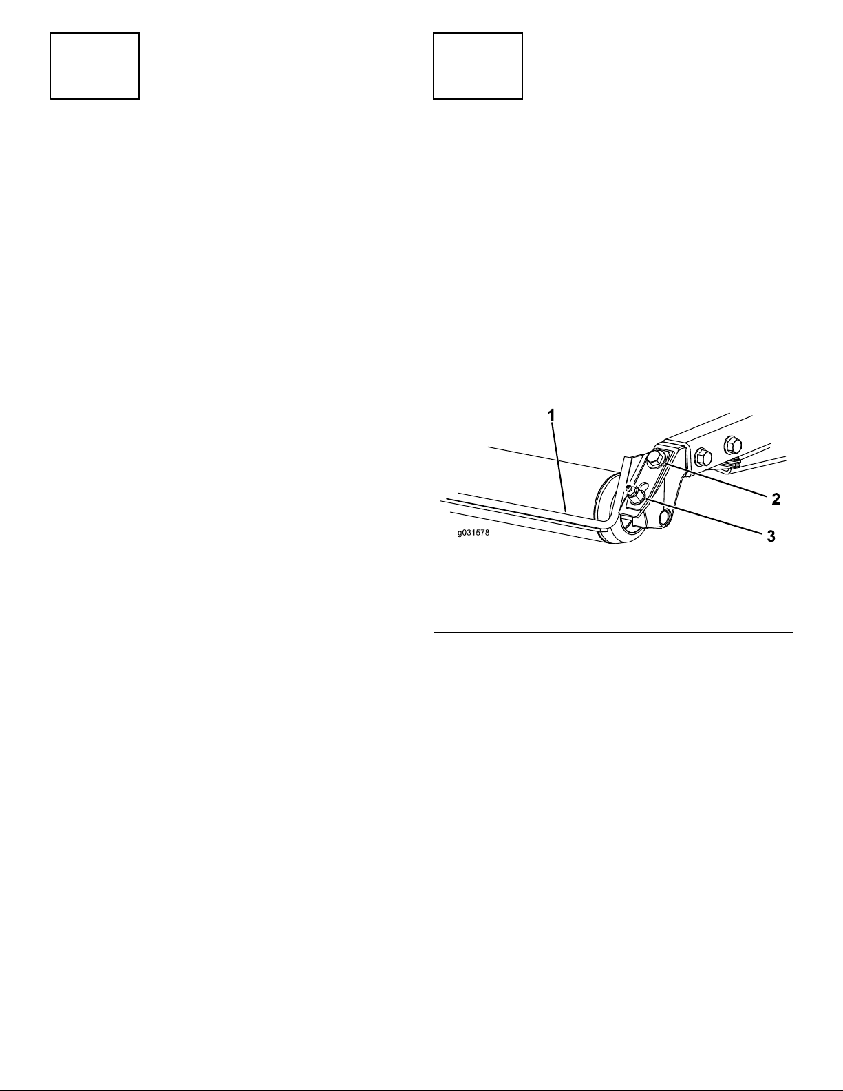
AdjustingtheRoller Scraper
Optional
NoPartsRequired
Procedure
Theoptionalrearrollerscraperfunctionsbestwhen
thereisanevengapof0.5to1mm(0.02to0.04inch)
betweenthescraperandtheroller.
1.Loosenthegreasettingandthemounting
screw(Figure3).
Figure3
1.Rollerscraper
2.Mountingscrew
2.Slidethescraperupordownuntilyouobtaina
gapof0.5to1mm(0.02to0.04inch)between
therodandtheroller.
3.Tightenthegreasettingandscrewto41N∙m
(30ft-lb)inanalternatingsequence.
3.Greasetting
g031578
10

4
5
InstallingtheMulching
Bafe
Optional
NoPartsRequired
Procedure
1.Thoroughlycleandebrisfromthemountingholes
ontherearwallandleftwallofthechamber.
2.Installthemulchingbafeintherearopening
andsecureitwith5ange-headbolts(Figure4).
PreparingtheMachine
NoPartsRequired
CheckingtheTirePressure
Checkthetirepressurebeforeuse;refertoChecking
theTirePressure(page23).
Important:Maintainpressureinalltiresto
ensureagoodquality-of-cutandpropermachine
performance.Donotunderinatethetires.
CheckingtheFluidLevels
1.Checktheengine-oillevelbeforestartingthe
engine;refertoCheckingtheEngine-OilLevel
(page51).
2.Checkthehydraulic-uidlevelbeforestarting
theengine;refertoCheckingtheHydraulic-Fluid
Level(page60).
3.Checkthecoolingsystembeforestartingthe
engine;refertoCheckingtheCoolingSystem
(page57).
Figure4
1.Mulchingbafe
3.Verifythatthemulchingbafedoesnotinterfere
withthetipofthebladeanddoesnotprotrude
insidethesurfaceoftherearchamberwall.
2.Flange-headbolt
DANGER
Usingthehigh-liftbladewiththe
mulchingbafecouldcausetheblade
tobreak,resultinginpersonalinjuryor
death.
Donotusethehigh-liftbladewiththe
bafe.
GreasingtheMachine
g031579
Greasethemachinebeforeuse;refertoGreasingthe
BearingsandBushings(page48).Failuretoproperly
greasethemachineresultsinprematurefailureof
criticalparts.
11

ProductOverview
BrakePedal
Pressthebrakepedal(Figure5)tostopthemachine.
Controls
Tilt-SteeringPedal
TractionPedal
Thetractionpedal(Figure5)controlstheforwardand
reverseoperation.Pressthetopofthepedaltomove
forwardandthebottomtomoverearward.Ground
speeddependsonhowfaryoupressthepedal.For
noload,maximumgroundspeed,fullypressthepedal
whilethethrottleisintheFASTposition.
Tostop,reducefootpressureonthetractionpedal
andallowittoreturntothecenterposition.
Mow-SpeedLimiter
Whenthemow-speedlimiter(Figure5)isippedupit
willcontrolthemowspeedandallowthecuttingdecks
tobeengaged.Eachspaceradjuststhemowing
speedby0.8km/h(0.5mph).Themorespacers
youhaveonthetopofthebolt,thesloweryouwill
go.Fortransport,ipbackthemowspeedlimiterfor
maximum-transportspeed.
Totiltthesteeringwheeltowardyou,pressthefoot
pedaldown,pullthesteeringtowertowardyouto
themostcomfortableposition,andreleasethepedal
(Figure5).Tomovethesteeringwheelawayfrom
you,pressthefootpedalandreleaseitwhenthe
steeringwheelreachesthedesiredoperatingposition.
ParkingBrake
Toengagetheparkingbrake,(Figure5)pushdown
thebrakepedalandpressthetopforwardtolatch.To
disengagetheparkingbrake,pressthebrakepedal
untiltheparking-brakelatchretracts.
Figure5
1.Tractionpedal4.Brakepedal
2.Mow-speedlimiter5.Parkingbrake
3.Spacers
6.Tilt-steeringpedal
Engine-SpeedSwitch
Theengine-speedswitch(Figure6)has2modesto
changetheenginespeed.Taptheswitchtoincrease
ordecreasetheenginespeedin100rpmincrements.
Holdtheswitchdowntoautomaticallymovethe
enginetoHighorLowidle,dependingonwhichend
oftheswitchthatyoupress.
g003955
12
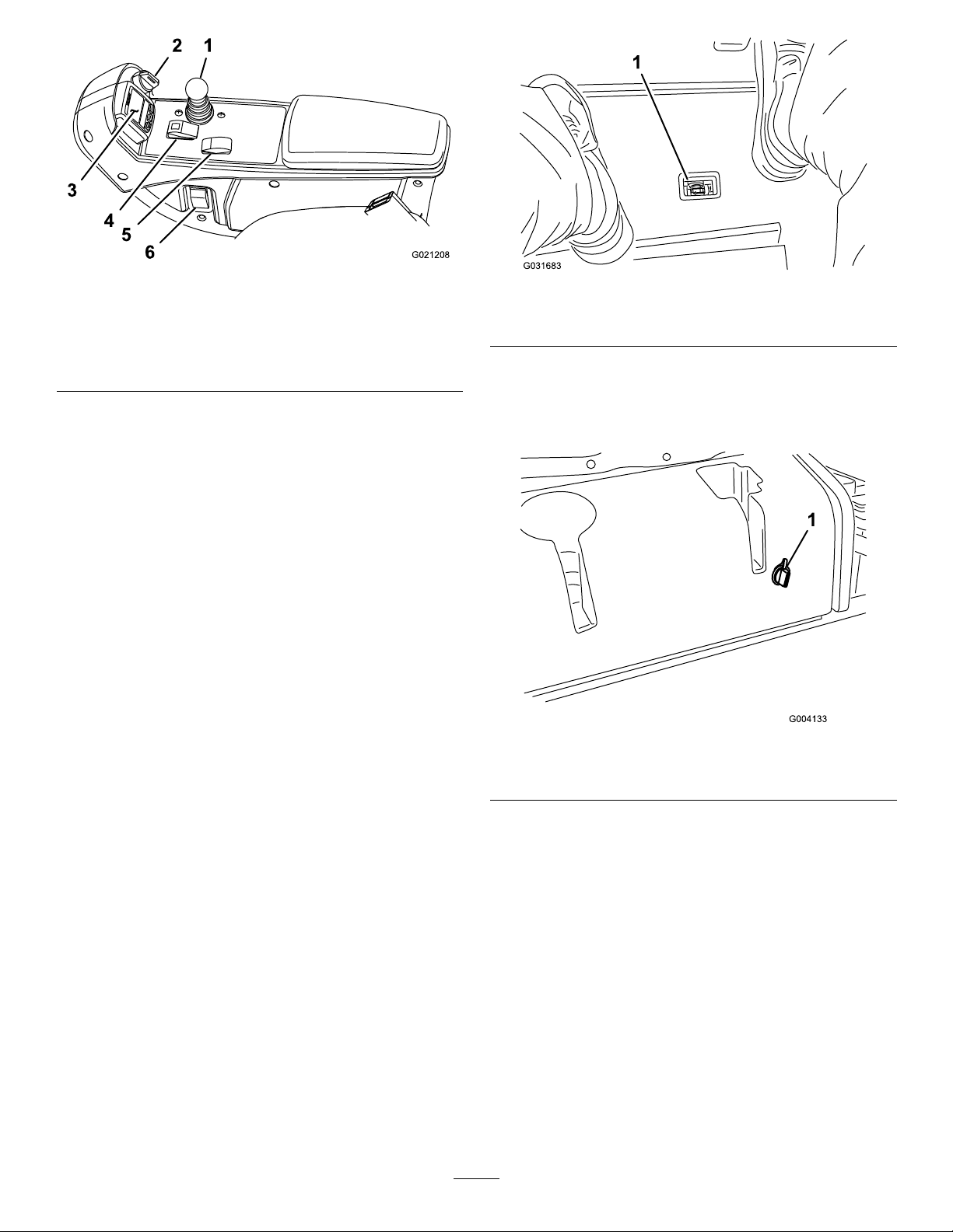
Figure6
1.Lowermow/raisecontrol
lever
2.Keyswitch5.Engine-speedswitch
3.InfoCenter
4.Enable/disableswitch
6.Headlightswitch
KeySwitch
Thekeyswitch(Figure6)has3positions:OFF,
ON/PREHEAT,andSTART.
LowerMow/RaiseControlLever
Thelowermow/raisecontrollever(Figure6)raises
andlowersthecuttingunitsandalsostartsandstops
themowerswhenthemowersareenabledinthemow
mode.Whenstartingthecuttingunitsinthedown
position,thisleverwillturnthecuttingunitsonifthe
PTOandthemowspeedlimiterareengaged.
g021208
Figure7
1.Hydraulic-lter-restrictionindicator
g031683
PowerPoint
Thepowerpoint(Figure8)isa12Vpowersupplyfor
electronicdevices.
HeadlightSwitch
Pivottheswitchdownwardtoturnontheheadlights
(Figure6).
Enable/DisableSwitch
Usetheenable/disableswitch(Figure6)inconjunction
withthelowermow/raisecontrollevertooperatethe
mowers.Themowerscannotbeloweredwhenthe
mow/transportleverisintheTRANSPORTposition.
Hydraulic-Filter-Restriction
Indicator
Thehydraulic-lter-restrictionindicatoralertsyou
whenthehydraulicltersmustbechanged;referto
ReplacingtheHydraulicFilters(page62).
g004133
Figure8
1.Powerpoint
InfoCenter
TheInfoCenterLCDdisplayshowstheoperating
status,variousdiagnostics,andotherinformation
aboutthemachine(Figure6).
UsingtheInfoCenterLCDDisplay
TheInfoCenterLCDdisplayshowsinformationabout
yourmachine,suchastheoperatingstatus,various
diagnosticsandotherinformationaboutthemachine
(Figure9).Thereisasplashscreenandmain
informationscreenoftheInfoCenter.Youcanswitch
betweenthesplashscreenandmaininformation
screenatanytimebypressinganyoftheInfoCenter
buttonsandthenselectingtheappropriatedirectional
arrow.
13
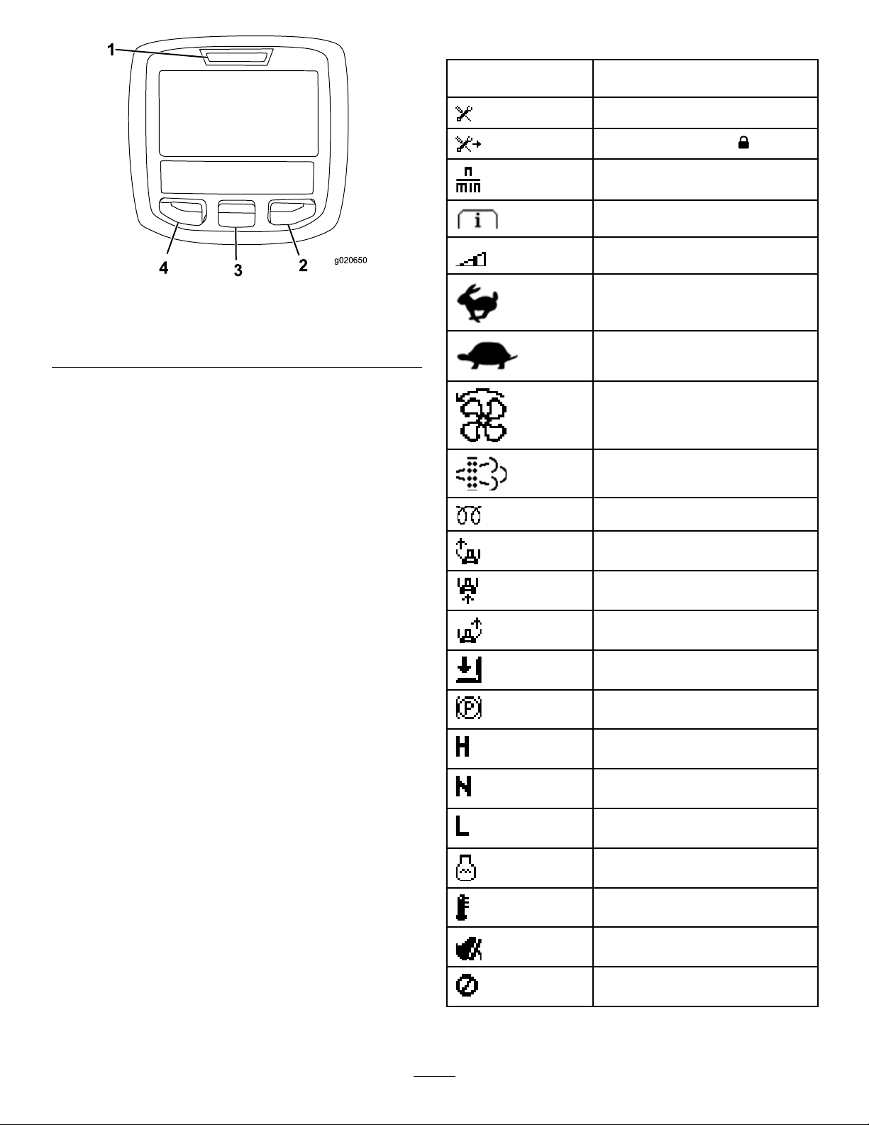
InfoCenterIconDescription
Figure9
1.Indicatorlight3.Middlebutton
2.Rightbutton
4.Leftbutton
•LeftButton,MenuAccess/BackButton—pressthis
buttontoaccesstheInfoCentermenus.Youcan
useittoexitanymenuthatyouarecurrentlyusing.
•MiddleButton—usethisbuttontoscrolldown
menus.
SERVICEDUE
g020650
Indicateswhenscheduledservice
shouldbeperformed
Hoursremaininguntilservice
Resettheservicehours
Thestatusoftheenginespeed(rpm)
Infoicon
Maximumtractionspeedsetting
Fast
Slow
Thefanisreversed.
Stationaryregenerationisrequired.
•RightButton—usethisbuttontoopenamenu
wherearightarrowindicatesadditionalcontent.
•Beeper—activatedwhenloweringthecuttingunits
orforadvisoriesandfaults.
Note:Thepurposeofeachbuttonmaychange
dependingonwhatisrequiredatthetime.Each
buttonislabeledwithanicondisplayingitscurrent
function.
Theair-intakeheaterisactive.
Raisetheleftcuttingunit.
Raisethecentercuttingunit.
Raisetherightcuttingunit.
Theoperatormustsitintheseat.
Theparkingbrakeisengaged.
Therangeishigh.
Neutral
IdentiestherangeasLow
Coolanttemperature(°Cor°F)
Temperature(hot)
TractionorTractionPedal
Notallowed
14
InfoCenterIconDescription(cont'd.)
InfoCenterIconDescription(cont'd.)
Starttheengine.
ThePTOison.
Thecruisecontrolison.
Shutofftheengine
Engine
Keyswitch
Cuttingunitsarelowering
Cuttingunitsareraising
PINcode
Hydraulicuidtemperature
CANbus
InfoCenter
Operatorshouldchangetoindicated
state
Symbolsareoftencombinedtoformsentences.Some
examplesareshownbelow.
Operatorshouldputmachinein
neutral
Enginestartisdenied
Engineshutdown
Enginecoolantistoohot
Hydraulicuidistoohot
DPFashaccumulationnotication.
RefertoServicingtheDiesel
ParticulateFilter(DPF)inthe
maintenancesectionfordetails
Reset-standbyregenerationrequest
Parkedorrecoveryregeneration
request
Aparkedorrecoveryregenerationis
processing.
Badorfailed
Center
Right
Left
Bulb
Highexhausttemperature
Thepowertake-offisdisabled.
Sitdownorengagetheparking
brake.
AccessibleonlybyenteringPIN
OutputofTECcontrollerorcontrol
wireinharness
Overtheallowedrange
Undertheallowedrange
Outofrange
/
Switch
Operatormustreleaseswitch
15

UsingtheMenus
ToaccesstheInfoCentermenusystem,pressthe
menuaccessbuttonwhileatthemainscreen.This
bringsyoutothemainmenu.Refertothefollowing
tablesforasynopsisoftheoptionsavailablefrom
themenus:
MainMenu—MenuItemDescription
Faults
ServiceContainsinformationonthe
Diagnostics
Settings
AboutListsthemodelnumber,serial
Service—MenuItem
Hours
Counts
DPFRegeneration
InhibitRegenUsetocontrolreset
ParkedRegenUsetoinitiateaparked
LastRegenListsthenumberhourssince
RecoverRegenUsetoinitiatearecovery
Containsalistoftherecent
machinefaults.Referto
theServiceManualoryour
authorizedTorodistributorfor
moreinformationontheFaults
menuandtheinformation
containedthere.
machinesuchashoursofuse,
counters,andothersimilar
numbers
Displaysthestateofeach
machineswitch,sensor,and
controloutput.Y oucanuse
thistotroubleshootcertain
issuesasitquicklytellsyou
whichmachinecontrolsare
ONandwhichareOFF.
Allowsyoutocustomizeand
modifycongurationvariables
ontheInfoCenterdisplay.
number,andsoftwareversion
ofyourmachine.
Description
Liststhetotalnumberofhours
thatthemachine,engine,and
PTOhavebeenon,aswell
asthenumberofhoursthe
machinehasbeentransported
andservicedue
Listsnumerouscountsthe
machinehasexperienced.
Thedieselparticulatelter
regenerationoptionandDPF
submenus
regeneration
regeneration
thelastreset,parked,or
recoveryregeneration
regeneration
Hi/LowRangeIndicatestheinputs,qualiers,
PTOIndicatestheinputs,qualiers,
EngineRun
Settings—MenuItem
Units
Language
LCDBacklightControlsthebrightnessofthe
LCDContrastControlsthecontrastofthe
ProtectedMenus
ProtectSettings
Counterbalance
andoutputsfordrivingin
transportmode
andoutputsforenablingthe
PTOcircuit
Indicatestheinputs,qualiers,
andoutputsforstartingthe
engine
Description
Controlstheunitsusedonthe
InfoCenter(EnglishorMetric)
Controlsthelanguageused
ontheInfoCenter*
LCDdisplay
LCDdisplay
Allowsapersonauthorized
byyourcompanywiththe
PINcodetoaccessprotected
menus
Allowstheabilitytochange
thesettingsintheprotected
settings
Controlstheamountof
counterbalanceappliedtothe
cuttingdecks
ProtectedunderProtectedMenus—accessibleonly
byenteringPIN
About—MenuItemDescription
Model
SNListstheserialnumberofthe
MachineControllerRevisionListsthesoftwarerevisionof
InfoCenterRevisionListsthesoftwarerevisionof
CANBus
Liststhemodelnumberofthe
machine
machine
themastercontroller
theInfoCenter
Liststhemachine
communicationbusstatus
Diagnostics—MenuItemDescription
CuttingUnitsIndicatestheinputs,qualiers,
andoutputsforraisingand
loweringthecuttingunits
16

ProtectedMenus
Thereare2operatingcongurationsettingsthatare
adjustablewithintheSettingsMenuoftheInfoCenter:
autoidletimedelayandcounterbalance.T olock
thesesettings,usetheProtectedMenu.
Note:Atthetimeofdelivery ,theinitialpassword
codeisprogrammedbyyourdistributor.
AccessingProtectedMenus
Note:ThefactorydefaultPINcodeforyoumachine
iseither0000or1234.
IfyouchangedthePINcodeandforgotthecode,
contactyourauthorizedT orodistributorforassistance.
1.FromtheMAINMENU,usethecenterbuttonto
scrolldowntotheSETTINGSMENUandpressthe
rightbutton(Figure10).
g028522
Figure11
Figure10
2.IntheSETTINGSMENU,usethecenterbuttonto
scrolldowntothePROTECTEDMENUandpress
therightbutton(Figure11A).
3.ToenterthePINcode,pressthecenterbutton
untilthecorrectrstdigitappears,thenpress
therightbuttontomoveontothenextdigit
(Figure11BandFigure11C).Repeatthisstep
g028523
untilthelastdigitisenteredandpresstheright
buttononcemore.
4.PressthemiddlebuttontoenterthePINcode
(Figure11D).
WaituntiltheredindicatorlightoftheInfoCenter
illuminates.
Note:IftheInfoCenteracceptsthePINcode
andtheprotectedmenuisunlocked,theword
“PIN”displaysintheupperrightcornerofthe
screen.
Note:RotatethekeyswitchtotheOFFpositionand
thentotheONpositionlockstheprotectedmenu.
YoucanviewandchangethesettingsintheProtected
Menu.OnceyouaccesstheProtectedMenu,scroll
downtoProtectSettingsoption.Usetherightbutton
tochangethesetting.SettingtheProtectSettingsto
OFFallowsyoutoviewandchangethesettingsin
theProtectedMenuwithoutenteringthePINcode.
SettingtheProtectSettingstoONhidestheprotected
optionsandrequiresyoutoenterthePINcodeto
changethesettingintheProtectedMenu.Afteryou
setthePINcode,rotatethekeyswitchOFFandback
totheONpositiontoenableandsavethisfeature.
17

ViewingandChangingthe
ProtectedMenuSettings
1.IntheProtectedMenu,scrolldowntoProtect
Settings.
2.Toviewandchangethesettingswithoutentering
aPINcode,usetherightbuttontochangethe
ProtectSettingstoOFF.
3.ToviewandchangethesettingswithaPIN
code,usetheleftbuttontochangetheProtect
SettingstoON,setthePINcode,andturnthe
keyintheignitionswitchtotheOFFpositionand
thentotheONposition.
SettingtheCounterbalance
1.IntheSettingsMenu,scrolldownto
Counterbalance.
2.Presstherightbuttontoselectcounterbalance
andchangebetweenthelow,medium,andhigh
settings.
SettingtheAutoIdle
1.IntheSettingsMenu,scrolldowntoAutoIdle.
2.Presstherightbuttontochangetheautoidle
timebetweenOFF,8S,10S,15S,20S,and30S.
18

Specications
Note:Specicationsanddesignaresubjecttochangewithoutnotice.
Figure12
g193881
19

DescriptionFigure12
Overallheight
Wheeltread(tirecentertocenter)rear
Overallwidth(transportposition)C231cm(91inches)
Overallwidth(mowingposition)
Wheelbase
reference
A
B
D
E
DimensionorWeight
217cm(85.5inches)
185cm(72.5inches)
247cm(97inches)
152cm(60inches)
Overalllength(transportposition)
Overalllength(mowingposition)G315cm(124inches)
Fuel-tankcapacity
Transportspeed
Mowingspeed
Netweight(withcuttingdecksanduids)1492kg(3,289lb)
F
315cm(124inches)
51L(13.5USgallons)
0to16km/h(0to10mph)
0to13km/h(0to8mph)
CuttingUnitSpecications
Length
Width
Height
Weight
86.4cm(34inches)
86.4cm(34inches)
24.4cm(9.6inches)tocarriermount
26.7cm(10–1/2inches)at3/4inchheightofcut
34.9cm(13–3/4inches)at4inchheightofcut
88kg(195lb)
Attachments/Accessories
AselectionofToroapprovedattachmentsandaccessoriesisavailableforusewiththemachinetoenhance
andexpanditscapabilities.ContactyourAuthorizedServiceDealerorauthorizedT orodistributororgoto
www.T oro.comforalistofallapprovedattachmentsandaccessories.
Toensureoptimumperformanceandcontinuedsafetycerticationofthemachine,useonlygenuineToro
replacementpartsandaccessories.Replacementpartsandaccessoriesmadebyothermanufacturerscouldbe
dangerous,andsuchusecouldvoidtheproductwarranty .
20

Operation
FillingtheFuelTank
Note:Determinetheleftandrightsidesofthe
machinefromthenormaloperatingposition.
BeforeOperation
BeforeOperationSafety
GeneralSafety
•Neverallowchildrenoruntrainedpeopleto
operateorservicethemachine.Localregulations
mayrestricttheageoftheoperator.Theowner
isresponsiblefortrainingalloperatorsand
mechanics.
•Becomefamiliarwiththesafeoperationofthe
equipment,operatorcontrols,andsafetysigns.
•Knowhowtostopthemachineandshutoffthe
enginequickly.
•Checkthatoperator-presencecontrols,safety
switches,andshieldsareattachedandfunctioning
properly.Donotoperatethemachineunlessthey
arefunctioningproperly.
•Beforemowing,alwaysinspectthemachineto
ensurethattheblades,bladebolts,andcutting
assembliesareingoodworkingcondition.
Replacewornordamagedbladesandboltsinsets
topreservebalance.
FuelTankCapacity
Fueltankcapacity:53L(14USgallons)
FuelSpecication
Important:Useonlyultra-lowsulphurdiesel
fuel.Fuelwithhigherratesofsulfurdegrades
thedieseloxidationcatalyst(DOC),whichcauses
operationalproblemsandshortenstheservicelife
ofenginecomponents.
Failuretoobservethefollowingcautionsmay
damagetheengine.
•Neverusekeroseneorgasolineinsteadofdiesel
fuel.
•Nevermixkeroseneorusedengineoilwiththe
dieselfuel.
•Neverkeepfuelincontainerswithzincplatingon
theinside.
•Donotusefueladditives.
PetroleumDiesel
Cetanerating:45orhigher
Sulfurcontent:Ultra-lowsulfur(<15ppm)
•Inspecttheareawhereyouwillusethemachine
andremoveallobjectsthatthemachinecould
throw.
FuelSafety
•Useextremecareinhandlingfuel.Itisammable
anditsvaporsareexplosive.
•Extinguishallcigarettes,cigars,pipes,andother
sourcesofignition.
•Useonlyanapprovedfuelcontainer.
•Donotremovethefuelcaporllthefueltank
whiletheengineisrunningorhot.
•Donotaddordrainfuelinanenclosedspace.
•Donotstorethemachineorfuelcontainerwhere
thereisanopename,spark,orpilotlight,such
asonawaterheaterorotherappliance.
•Ifyouspillfuel,donotattempttostarttheengine;
avoidcreatinganysourceofignitionuntilthefuel
vaporshavedissipated.
21

FuelTable
AddingFuel
Dieselfuelspecication
ASTMD975
No.1-DS15
No.2-DS15
EN590EuropeanUnion
ISO8217DMX
JISK2204GradeNo.2
KSM-2610
Location
USA
International
Japan
Korea
•Useonlyclean,freshdieselfuelorbiodieselfuels.
•Purchasefuelinquantitiesthatcanbeusedwithin
180daystoensurefuelfreshness.
Usesummer-gradedieselfuel(No.2-D)at
temperaturesabove-7°C(20°F)andwinter-grade
fuel(No.1-DorNo.1-D/2-Dblend)belowthat
temperature.
Note:Usingwinter-gradefuelatlowertemperatures
provideslowerashpointandcoldowcharacteristics
whicheasesstartingandreducesfuellterplugging.
Usingsummer-gradefuelabove-7°C(20°F)
contributestowardlongerfuelpumplifeandincreased
powercomparedtowinter-gradefuel.
g194207
UsingBiodiesel
Thismachinecanalsouseabiodiesel-blendedfuelof
uptoB20(20%biodiesel,80%petrodiesel).
Sulfurcontent:Ultra-lowsulfur(<15ppm)
Biodieselfuelspecication:ASTMD6751or
EN14214
Blendedfuelspecication:ASTMD975,EN590,
orJISK2204
Important:Thepetroleumdieselportionmust
beultra-lowsulfur.
Observethefollowingprecautions:
•Biodieselblendsmaydamagepaintedsurfaces.
•UseB5(biodieselcontentof5%)orlesserblends
incoldweather.
•Monitorseals,hoses,gasketsincontactwithfuel
astheymaydegradeovertime.
•Fuellterpluggingmayoccurforatimeafteryou
converttobiodieselblends.
g031869
Figure13
Fillthetanktoabout6to13mm(1/4to1/2inch)
belowthetopofthetank,notthellerneck,with
Number2-Ddieselfuel.
Note:Ifpossible,llthefueltankaftereachuse;this
willminimizepossiblebuildupofcondensationinside
thefueltank.
•Formoreinformationonbiodiesel,contactyour
authorizedT orodistributor.
22

CheckingtheEngine-Oil Level
Beforeyoustarttheengineandusethemachine,
checktheoillevelintheenginecrankcase;referto
CheckingtheEngine-OilLevel(page51).
CheckingtheCooling System
Beforeyoustarttheengineandusethemachine,
checkthecoolingsystem;refertoCheckingthe
CoolingSystem(page23).
CheckingtheHydraulic System
Beforeyoustarttheengineandusethemachine,
checkthehydraulicsystem;refertoCheckingthe
HydraulicLinesandHoses(page63).
DrainingtheWater Separator
Drainwaterorothercontaminantsfromthewater
separator;refertoServicingtheWaterSeparator
(page54).
CheckingtheTirePressure
g001055
Figure14
CheckingtheTorqueofthe Wheel-LugNuts
ServiceInterval:Afterthersthour
Aftertherst10hours
Every250hours
WARNING
Failuretomaintainthepropertorqueofthe
wheelnutscouldresultinfailureorlossofa
wheel,andmayresultinpersonalinjury.
Torquethefrontandrear-wheelnutsto94to
122N·m(70to90ft-lb)attherecommended
serviceintervals.
ServiceInterval:Beforeeachuseordaily
Thecorrectairpressureinthefrontandreartiresis
83to103kPa(12to15psi).
Important:Maintainpressureinalltiresto
ensureagoodqualityofcutandpropermachine
performance.Donotunder-inatethetires.
Checktheairpressureinallthetiresbefore
operatingthemachine.
23

AdjustingtheHeightofCut
Important:Thiscuttingdeckoftencuts
approximately6mm(1/4inch)lowerthanareel
cuttingunitwiththesamebenchsetting.Itmay
benecessarytohavethebenchoftherotary
cuttingdeckset6mm(1/4inch)abovethatof
reelscuttinginthesamearea.
Important:Accesstotherearcuttingunitsis
greatlyimprovedbyremovingthecuttingunit
fromthetractor.Iftheunitisequippedwitha
Sidewinder®,sidewindthecuttingunitstothe
right,removetherearcuttingunit,andslideitout
totherightside.
g026184
Figure16
6.Positionthetappedplatein-linewiththespacer.
7.Installtheboltnger-tight.
8.Repeatstepsthroughforeachsideadjustment.
1.Lowerthecuttingdecktotheground,shutoff
theengine,andremovethekeyfromtheignition
switch.
2.Loosentheboltsecuringeachheight-of-cut
brackettotheheight-of-cutplate(frontandeach
side)asshowninFigure15.
3.Beginningwiththefrontadjustment,removethe
bolt.
Figure15
9.Torqueall3boltsto41N∙m(30ft-lb).Always
tightenthefrontboltrst.
Note:Adjustmentsofmorethan3.8cm(1-1/2
inches)mayrequiretemporaryassemblytoan
intermediateheighttopreventbinding(e.g.,
changingfrom3.1to7cm(1-1/4to2-3/4inches)
heightofcut).
g011344
1.Height-of-cutbracket3.Spacer
2.Height-of-cutplate
4.Whilesupportingthechamber,removethe
spacer(Figure15).
5.Movethechambertothedesiredheightof
cutandinstallaspacerintothedesignated
height-of-cutholeandslot(Figure16).
24

Checkingthe
BurnishingtheBrakes
Safety-InterlockSwitches
ServiceInterval:Beforeeachuseordaily
CAUTION
Ifthesafety-interlockswitchesare
disconnectedordamaged,themachinecould
operateunexpectedlyandcausepersonal
injury.
•Donottamperwiththesafety-interlock
switches.
•Checktheoperationofthesafety-interlock
switchesdailyandreplaceanydamaged
switchesbeforeoperatingthemachine.
Themachinehasinterlockswitchesintheelectrical
system.Theseswitchesdisengageeitherthetraction
orthePTOwheneveryouleavetheseat.Although
theenginecontinuestorunifyoudisengagethePTO
switch,andyoureleasethetractionpedal,shutoffthe
enginebeforerisingfromtheseat.
1.Parkthemachineonalevelsurface,lowerthe
cuttingunit,shutofftheengine,andengagethe
parkingbrake.
Toensureoptimumperformanceoftheparking-brake
system,burnish(breakin)thebrakesbeforeuse.
Settheforwardtractionspeedto6.4km/h(4mph)
tomatchthereversetractionspeed(all8spacers
movedtothetopofthemow-speedcontrol).With
theengineathighidle,proceedforwardwiththe
mow-speed-controlstopengagedandridethebrake
for15seconds.Proceedbackwardatfullreverse
speedandridethebrakefor15seconds.Repeatthis
5times,waiting1minutebetweeneachforwardand
reversecycletoavoidoverheatingthebrakes;referto
AdjustingtheParkingBrakes(page59).
SelectingaBlade
UsingaStandardCombination Sail
Thisbladeprovidesexcellentliftanddispersionin
almostanycondition.Ifyourequiremoreorlesslift
anddischargevelocity,consideradifferentblade.
Attributes:Excellentliftanddispersioninmost
conditions.
2.Pressthetractionpedal.Turnthekeyinthe
ignitionswitchtotheONposition.
Note:Iftheenginecranks,thereisa
malfunctionintheinterlocksystem.Correctthis
malfunctionbeforeoperatingthemachine.
3.TurnthekeyintheignitionswitchtotheON
position,starttheengine,risefromtheseat,and
movethePTOswitchtotheONposition.
Note:ThePTOshouldnotengage.Ifthe
PTOengages,thereisamalfunctioninthe
interlocksystem.Correctthismalfunctionbefore
operatingthemachine.
4.Engagetheparkingbrake,turnthekeyinthe
ignitionswitchtotheONposition,startthe
engine,andmovethetractionpedaloutofthe
NEUTRALposition.
Note:TheInfoCenterdisplays"tractiondenied"
andthemachineshouldnotmove.Ifthe
machinedoesmove,thereisamalfunctionin
theinterlocksystem.Correctthismalfunction
beforeoperatingthemachine.
UsinganAngled-SailBlade
Thebladegenerallyperformsbestinlowerheightsof
cut—1.9to6.4cm(3/4to2-1/2inches).
Attributes:
•Thedischargeremainsmoreevenatlowerheights
ofcut.
•Thedischargehaslesstendencytothrowleftand
thusleavesacleanerlookaroundbunkersand
fairways.
•Thereisalowerpowerrequirementatlower
heightsofcutandindenseturf.
UsinganAtomicBlade
Attributes:Thisbladeprovidesexcellentleaf
mulching.
5.StarttheenginewiththePTOengaged.
Note:Iftheenginecranks,thereisa
malfunctionintheinterlocksystem.Correctthis
malfunctionbeforeoperatingthemachine.
25
Understandingthe
Changingthe
DiagnosticLight
Themachineisequippedwithadiagnosticlight,which
indicatesifthemachinedetectsamalfunction.The
diagnosticlightislocatedontheInfoCenter,above
thedisplayscreen(Figure17).Whenthemachine
functionsproperlyandthekeyswitchismovedto
theON/RUNposition,thediagnosticlightturnson
brieytoindicatethatthelightisworkingproperly.
Whenamachineadvisorymessagedisplays,thelight
illuminateswhenthemessageispresent.Whena
faultmessageisdisplayed,thelightblinksuntilthe
faultisresolved.
CounterbalanceSettings
Youcanchangetheamountofrequiredcutting-unit
counterbalance(upwardlift)tomeetyourcurrent
mowingconditions.
1.Parkthemachineonalevelsurface,lowerthe
cuttingdecks,turnthekeyintheswitchtothe
OFFposition,andengagetheparkingbrake.
2.TurnthekeyintheswitchtotheRUNposition.
3.IntheInfoCenterSettingsMenu,scrolldownto
Counterbalance.
4.Presstherightbuttontoselectcounterbalance
andchangebetweenthelow,medium,andhigh
settings.
Note:Oncetheadjustmenthasbeen
completed,movethemachinetoatestareaand
operatethemachinewiththenewsetting.The
newcounterbalancedsettingmaychangethe
effectiveheightofcut.
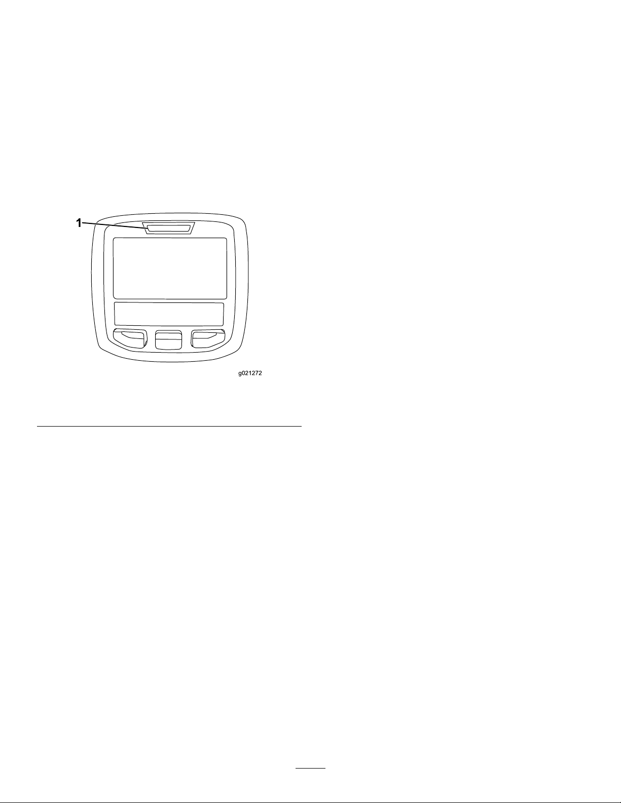
1.Diagnosticlight
g021272
Figure17
26

ChoosingAccessories
OptionalEquipmentCongurations
AngleSailBladeHigh-Lift,Parallel-Sail
GrassCutting:1.9to4.4
cm(3/4to1-3/4inches)
heightofcut
GrassCutting:5to6.4
cm(2to2-1/2inches)
heightofcut
GrassCutting:7to10
cm(2-3/4to4inches)
heightofcut
LeafMulchingRecommendedforuse
ProsEvendischargeatlower
ConsDoesnotliftthegrass
Recommendedinmost
applications
Recommendedforthick
orlushturf
Mayworkwellinlushturf
withthemulchingbafe
heightofcut;cleaner
lookaroundbunkersand
fairways;lowerpower
requirements
wellinhighheight-of-cut
applications;wetor
stickygrasshasa
tendencytobuildupin
thechamber,leading
topoorqualityofcut
andhigherpower
requirements
Blade(Donotusewith
themulchingbafe)
Mayworkwellinlightor
sparseturf
Recommendedforlight
orsparseturf
Recommendedinmost
applications
NotAllowedUsewithcombination
Moreliftandhigher
dischargevelocity;
sparseorlimpturfis
pickedupathighheight
ofcut;wetorsticky
clippingsaredischarged
efciently
Requiresmorepowerto
runinsomeapplications;
tendstowindrowat
lowerheightofcutin
lushgrass;donotuse
withthemulchingbafe
MulchingBafeRollerScraper
Hasbeenshownto
improvedispersionand
after-cutperformance
onnortherngrassesthat
arecutatleast3times
perweekandlessthan
1/3ofthegrassblade
isremoved.Donot
usewiththehigh-lift,
parallel-sailblade
sailoranglesailblade
only
Mayimprovedispersion
andappearancein
certaingrasscutting
applications;verygood
forleafmulching
Grasswillbuildupinthe
chamberifyouattempt
toremovetoomuch
grasswiththebafein
place
Useitwheneverthe
rollersbuildupwith
grassorlarge,atgrass
clumpsofgrassare
seen.Thescrapersmay
increaseclumpingin
certainapplications.
Reducesrollerbuildup
incertainapplications
27

DuringOperation
•Beforeleavingtheoperatingposition(including
toemptythecatchersortounclogthechute),do
thefollowing:
DuringOperationSafety
GeneralSafety
•Theowner/operatorcanpreventandisresponsible
foraccidentsthatmaycausepersonalinjuryor
propertydamage.
•Wearappropriateclothing,includingeye
protection;longpants;substantial,slip-resistant
footwear;andhearingprotection.Tiebacklong
hairanddonotwearloosejewelry .
•Useyourfullattentionwhileoperatingthe
machine.Donotengageinanyactivitythat
causesdistractions;otherwise,injuryorproperty
damagemayoccur.
•Donotoperatethemachinewhileill,tired,or
undertheinuenceofalcoholordrugs.
•Nevercarrypassengersonthemachineandkeep
bystandersandpetsawayfromthemachine
duringoperation.
•Operatethemachineonlyingoodvisibilitytoavoid
holesorhiddenhazards.
•Beforeyoustarttheengine,ensurethatalldrives
areinneutral,theparkingbrakeisengaged,and
youareintheoperatingposition.
•Keepyourhandsandfeetawayfromrotating
parts.Keepclearofthedischargeopeningatall
times.
•Lookbehindanddownbeforebackinguptobe
sureofaclearpath.
•Usecarewhenapproachingblindcorners,shrubs,
trees,orotherobjectsthatmayobscureyour
vision.
•Stopthebladeswheneveryouarenotmowing.
•Stopthemachine,removethekey,andwaitfor
allmovingpartstostopbeforeinspectingthe
attachmentafterstrikinganobjectorifthereis
anabnormalvibrationinthemachine.Makeall
necessaryrepairsbeforeresumingoperation.
•Slowdownandusecautionwhenmakingturns
andcrossingroadsandsidewalkswiththe
machine.Alwaysyieldtheright-of-way.
•Disengagethedrivetothecuttingunit,shut
offtheengine,removethekey,andwaitforall
movingpartstostopbeforeadjustingtheheightof
cut(unlessyoucanadjustitfromtheoperating
position).
•Neverrunanengineinanareawhereexhaust
gassesareenclosed.
•Neverleavearunningmachineunattended.
–Parkthemachineonlevelground.
–Disengagethepowertakeoffandlowerthe
attachments.
–Engagetheparkingbrake.
–Shutofftheengineandremovethekey.
–Waitforallmovingpartstostop.
•Donotoperatethemachinewhenthereistherisk
oflightning.
•Donotusethemachineasatowingvehicle.
•Useaccessories,attachments,andreplacement
partsapprovedbyTheT oro®Companyonly.
RolloverProtectionSystem (ROPS)Safety
•DonotremovetheROPSfromthemachine.
•Ensurethattheseatbeltisattachedandthatyou
canreleaseitquicklyinanemergency.
•Checkcarefullyforoverheadobstructionsanddo
notcontactthem.
•KeeptheROPSinsafeoperatingconditionby
thoroughlyinspectingitperiodicallyfordamage
andkeepingallthemountingfastenerstight.
•ReplacedamagedROPScomponents.Donot
repairoralterthem.
MachineswithaFixedRollBar
•TheROPSisanintegralsafetydevice.
•Alwayswearyourseatbelt.
SlopeSafety
•Slopesareamajorfactorrelatedtolossofcontrol
androlloveraccidents,whichcanresultinsevere
injuryordeath.Y ouareresponsibleforsafeslope
operation.Operatingthemachineonanyslope
requiresextracaution.
•Evaluatethesiteconditionstodetermineifthe
slopeissafeformachineoperation,including
surveyingthesite.Alwaysusecommonsense
andgoodjudgmentwhenperformingthissurvey .
•Reviewtheslopeinstructionslistedbelowfor
operatingthemachineonslopesandtodetermine
whetheryoucanoperatethemachineinthe
conditionsonthatdayandatthatsite.Changes
intheterraincanresultinachangeinslope
operationforthemachine.
28

•Avoidstarting,stopping,orturningthemachineon
slopes.Avoidmakingsuddenchangesinspeedor
direction.Maketurnsslowlyandgradually.
•Donotoperateamachineunderanyconditions
wheretraction,steering,orstabilityisinquestion.
•Removeormarkobstructionssuchasditches,
holes,ruts,bumps,rocks,orotherhiddenhazards.
Tallgrasscanhideobstructions.Uneventerrain
couldoverturnthemachine.
•Beawarethatoperatingthemachineonwet
grass,acrossslopes,ordownhillmaycausethe
machinetolosetraction.Lossoftractiontothe
drivewheelsmayresultinslidingandalossof
brakingandsteering.
•Useextremecautionwhenoperatingthemachine
neardrop-offs,ditches,embankments,water
hazards,orotherhazards.Themachinecould
suddenlyrolloverifawheelgoesovertheedge
ortheedgecavesin.Establishasafetyarea
betweenthemachineandanyhazard.
•Identifyhazardsatthebaseoftheslope.
Iftherearehazards,mowtheslopewitha
pedestrian-controlledmachine.
•Ifpossible,keepthecuttingunit(s)loweredtothe
groundwhileoperatingonslopes.Raisingthe
cuttingunit(s)whileoperatingonslopescancause
themachinetobecomeunstable.
•Useextremecautionwithgrass-collectionsystems
orotherattachments.Thesecanchangethe
stabilityofthemachineandcausealossofcontrol.
Alwayskeepthemachineingearwhengoing
downslopes.Donotcoastdownhill(applicable
onlytogear-driveunits).
StartingtheEngine
Important:Thefuelsystemautomaticallybleeds
itselfbeforestartingtheengineifyouarestarting
theengineforthersttime,theenginehasshut
offduetolackoffuel,oryouhaveperformed
maintenanceonthefuelsystem.
1.Sitontheseat,keepyourfootoffthetraction
pedalsothatitisinNEUTRAL,engagetheparking
brake,settheengine-speedswitchtotheMID
position,andensurethattheEnable/Disable
switchisintheDISABLEposition.
2.TurnthekeyintheswitchtotheRUNposition.
3.Whentheglowindicatordims,turnthekeyinthe
switchtotheST ARTposition.Releasethekey
immediatelywhentheenginestartsandallowit
toreturntotheRUNposition.
4.Runtheengineatlowidlespeeduntilitwarms
up.
ShuttingOfftheEngine
1.MoveallcontrolstoNEUTRAL,engagethe
parkingbrake,movetheengine-speedswitchto
theLOWIDLEpositionandallowtheengineto
reachlowidlespeed.
Important:Allowtheenginetoidlefor5
minutesbeforeshuttingitoffafterafull
loadoperation.Failuretodosomayleadto
troubleonaturbo-chargedengine.
2.TurnthekeyintheswitchtotheOFFposition
andremovethekey.
CuttingGrasswiththe Machine
Note:Cuttinggrassataratethatloadstheengine
promotesDPFregeneration.
1.Movethemachinetothejobsite.
2.Wheneverpossible,settheengine-speedswitch
tohighidle.
3.EngagethePTOswitch.
4.Graduallymovethetractionpedalforwardand
slowlydrivethemachineoverthemowingarea.
5.Oncethefrontofthecuttingunitsareoverthe
mowingarea,lowerthecuttingunits.
6.Cutgrasssothatthebladescancutand
dischargeclippingsatahighratewhile
producingagoodqualityofcut.
Note:Ifthecuttingrateistoohigh,thequality
ofcutmaydeteriorate.Reducetheground
speedofthemachineorreducethewidthofcut
toregainhighidleenginespeed.
29

7.Whenthecuttingunitsareoverthefaredgeof
themowingarea,liftthecuttingunits.
8.Performatear-shapedturntoquicklylineupfor
yournextpass.
DieselParticulateFilter Regeneration
Thedieselparticulatelter(DPF)ispartoftheexhaust
system.Thediesel-oxidationcatalystoftheDPF
reducesharmfulgassesandthesootlterremoves
sootfromtheengineexhaust.
TheDPFregenerationprocessusesheatfromthe
engineexhausttoincineratethesootaccumulatedon
thesootlter,convertingthesoottoash,andclears
thechannelsofthesootltersothatlteredengine
exhaustowsouttheDPF .
Theenginecomputermonitorstheaccumulationof
sootbymeasuringthebackpressureintheDPF.If
thebackpressureistoohigh,sootisnotincinerating
inthesootlterthroughnormalengineoperation.T o
keeptheDPFclearofsoot,rememberthefollowing:
•Passiveregenerationoccurscontinuouslywhile
theengineisrunning—runtheengineatfull
enginespeedwhenpossibletopromoteDPF
regeneration.
•IfthebackpressureintheDPFistoohighora
resetregenerationhasnotoccurredfor100hours,
theenginecomputersignalsyouthroughthe
InfoCenterwhenresetregenerationisrunning.
•Allowtheresetregenerationprocesstocomplete
beforeshuttingofftheengine.
Operateandmaintainyourmachinewiththefunction
oftheDPFinmind.Engineloadathighidle(full
throttle)enginespeedgenerallyproducesadequate
exhausttemperatureforDPFregeneration.
Important:Minimizetheamountoftimethatyou
idletheengineoroperatetheengineatlow-engine
speedtohelpreducetheaccumulationofsootin
thesootlter.
DPFSootAccumulation
•Overtime,thedieselparticulatelteraccumulates
sootinthesootlter.Thecomputerfortheengine
monitorsthesootlevelintheDPF .
•Whenenoughsootaccumulates,thecomputer
informsyouthatitistimetoregeneratetheDPF.
•DPFregenerationisaprocessthatheatstheDPF
toconvertthesoottoash.
•Inadditiontothewarningmessages,thecomputer
reducesthepowerproducedbytheengineat
differentsoot-accumulationlevels.
EngineWarningMessages—SootAccumulation
IndicationLevel
Level1:Engine
Warning
Level2:Engine
Warning
FaultCode
g213866
Figure18
CheckEngine
SPN3719,FMI16
g213867
Figure19
CheckEngine
SPN3719,FMI0
EnginePowerRatingRecommendedAction
Thecomputerde-ratesthe
enginepowerto85%.
Thecomputerde-ratesthe
enginepowerto50%.
Performaparkedregeneration
assoonaspossible;refer
toParkedorRecovery
Regeneration(page37).
Performarecoveryregeneration
assoonaspossible;refer
toParkedorRecovery
Regeneration(page37).
30

DPFAshAccumulation
•Thelighterashisdischargedthroughtheexhaust
system;theheavierashcollectsinthesootlter.
•Ashisaresidueoftheregenerationprocess.Over
time,thedieselparticulatelteraccumulatesash
thatdoesnotdischargewiththeengineexhaust.
•Thecomputerfortheenginecalculatestheamount
ofashaccumulatedintheDPF.
InfoCenterAdvisoryandEngineWarningMessages—AshAccumulation
•Whenenoughashaccumulates,theengine
computersendsinformationtotheInfoCenter
intheformofanenginefaulttoindicatethe
accumulationofashintheDPF.
•Thefaultmessagesindicatethatitistimeto
servicetheDPF.
•Inadditiontothewarnings,thecomputerreduces
thepowerproducedbytheengineatdifferent
ash-accumulationlevels.
Indication
Level1:
Engine
Warning
Level2:
Engine
Warning
Level3:
Engine
Warning
Level
FaultCode
g213863
EngineSpeed
Reduction
None
Figure20
EnginePowerRatingRecommendedAction
Thecomputer
de-ratestheengine
powerto85%.
ServicetheDPF;
refertoServicingthe
Diesel-OxidationCatalyst
(DOC)andtheSoot
Filter(page52)
CheckEngine
SPN3720,FMI16
ServicetheDPF;
refertoServicingthe
Diesel-OxidationCatalyst
(DOC)andtheSoot
Filter(page52)
g213863
Figure21
Thecomputer
None
de-ratestheengine
powerto50%.
CheckEngine
SPN3720,FMI16
ServicetheDPF;
refertoServicingthe
Diesel-OxidationCatalyst
(DOC)andtheSoot
Filter(page52)
g214715
Figure22
Enginespeedat
maximumtorque+
200rpm
Thecomputer
de-ratestheengine
powerto50%.
CheckEngine
SPN3251,FMI0
31

TypesofDieselParticulateFilterRegeneration
Typesofdieselparticulatelterregenerationthatareperformedwhilethemachineisoperating:
TypeofRegenerationConditionsthatcauseDPFregenerationDPFdescriptionofoperation
Passive
Assist
Reset
Occursduringnormaloperationofthemachineat
high-enginespeedorhigh-engineload
Occursbecauseoflow-enginespeed,low-engine
load,orafterthecomputerdetectstheDPFis
becomingobstructedwithsoot
Occursevery100hours
Alsooccursafterassistregenerationonlyifthe
computerdetectsthatassistregenerationdidnot
sufcientlyreducethesootlevel
•TheInfoCenterdoesnotdisplayaniconindicating
passiveregeneration.
•Duringpassiveregeneration,theDPFprocesses
high-heatexhaustgasses,oxidizingharmful
emissions,andburningsoottoash.
RefertoPassiveDPFRegeneration(page34).
•TheInfoCenterdoesnotdisplayaniconindicating
assistregeneration.
•Duringassistregeneration,theenginecomputer
adjuststheenginesettingstoraisetheexhaust
temperature.
RefertoAssistDPFRegeneration(page35).
•Whenthehighexhaust-temperatureicon
isdisplayedintheInfoCenter,aregenerationisin
progress.
•Duringresetregeneration,theenginecomputer
adjuststheenginesettingstoraisetheexhaust
temperature.
RefertoResetRegeneration(page35).
Typesofdieselparticulatelterregenerationthatrequireyoutoparkthemachine:
TypeofRegenerationConditionsthatcauseDPFregenerationDPFdescriptionofoperation
Parked
Occursbecausethecomputerdetectsback
pressureintheDPFduetosootbuildup
Alsooccursbecausetheoperatorinitiatesaparked
regeneration
MayoccurbecauseyousettheInfoCentertoinhibit
resetregenerationandcontinuedoperatingthe
machine,addingmoresootwhentheDPFalready
needsaresetregeneration
Mayresultfromusingtheincorrectfuelorengineoil
•Whenthereset-standby/parkedorrecovery
regenerationiconorADVISORY#188
displaysintheInfoCenter,aregenerationis
requested.
•Performtheparkedregenerationassoonas
possibletoavoidneedingarecoveryregeneration.
•Aparkedregenerationrequires30to60minutes
tocomplete.
•Youmusthaveatleasta1/4tankoffuelinthe
tank.
•Youmustparkthemachinetoperformaparked
regeneration.
RefertoParkedorRecoveryRegeneration(page
37).
32

Typesofdieselparticulatelterregenerationthatrequireyoutoparkthemachine:(cont'd.)
TypeofRegenerationConditionsthatcauseDPFregenerationDPFdescriptionofoperation
Recovery
Occursbecausetheoperatorignoredrequestsfor
aparkedregenerationandcontinuedoperatingthe
machine,addingmoresoottotheDPF
•Whenthereset-standby/parkedorrecovery
regenerationiconorADVISORY#190
displaysintheInfoCenter,arecoveryregeneration
isrequested.
•Arecoveryregenerationrequiresupto3hours
tocomplete.
•Youmusthaveatleasta1/2tankoffuelinthe
machine.
•Youmustparkthemachinetoperformarecovery
regeneration.
RefertoParkedorRecoveryRegeneration(page
37).
AccessingtheDPFRegeneration Menus
AccessingtheDPFRegenerationMenus
1.AccesstheServicemenu,pressthecenter
buttontoscrolldowntotheDPFREGENERATION
option(Figure23).
UsetheLASTREGENeldtodeterminehowmany
hoursyouhaveruntheenginesincethelastreset,
parked,orrecoveryregeneration.
g224693
Figure24
Figure23
2.PresstherightbuttontoselecttheDPF
Regenerationentry(Figure23).
TimeSinceLastRegeneration
AccesstheDPFRegenerationmenu,pressthecenter
buttontoscrolldowntotheLASTREGENeld(Figure
24).
g227667
TechnicianMenu
Important:Foroperatingconvenience,you
maydecidetoperformaparkedregeneration
beforethesootloadreaches100%,provided
theenginehasrunmorethan50hourssince
thelastsuccessfulreset,parked,orrecovery
regeneration.
Usethetechnicianmenutoviewthecurrentstateof
engineregenerationcontrolandviewthereported
sootlevel.
AccesstheDPFRegenerationmenu,pressthecenter
buttontoscrolldowntotheTECHNICIANoption,and
33

presstherightbuttontoselecttheT echnicianentry
(Figure25).
DPFOperationTable(cont'd.)
Figure25
•UsetheDPFoperationtabletounderstandthe
currentstateofDPFoperation(Figure26).
State
ResetRegenTheenginecomputerisrunningareset
ParkedStby
ParkedRegenYouinitiatedaparkedregeneration
Recov.Stby
Recov.RegenY ouinitiatedarecoveryregeneration
g227348
•Viewthesootloadwhichismeasuredasthe
percentageofsootintheDPF(Figure27);referto
Description
regeneration.
Theenginecomputerisrequestingthat
yourunaparkedregeneration.
requestandtheenginecomputeris
processingtheregeneration.
Theenginecomputerisrequestingthat
yourunarecoveryregeneration.
requestandtheenginecomputeris
processingtheregeneration.
thesoot-loadtable.
Note:Thesootloadvaluevariesasthemachine
isoperatedandDPFregenerationoccurs.
.
DPFOperationTable
State
NormalTheDPFisinnormal-operating
AssistRegen
ResetStby
Figure26
Description
mode—passiveregeneration.
Theenginecomputerisperformingan
assistregeneration.
Theengine
computeristrying
torunareset
regeneration,but
1ofthefollowing
conditionsprevents
regeneration:
Theregeninhibit
settingissettoON.
Theexhaust
temperature
istoolowfor
regeneration.
g227359
Figure27
Soot-LoadTable
ImportantSootLoadValuesRegenerationState
0%to5%
78%Theenginecomputerperforms
g227360
100%
122%
Minimumsootloadrange
anassistregeneration.
Theenginecomputer
automaticallyrequestsa
parkedregeneration.
Theenginecomputer
automaticallyrequestsa
recoveryregeneration.
PassiveDPFRegeneration
•Passiveregenerationoccursaspartofnormal
engineoperation.
•Whileoperatingthemachine,runtheengineat
full-enginespeedandhighloadwhenpossibleto
promoteDPFregeneration.
34

AssistDPFRegeneration
•Theenginecomputeradjustsenginesettingsto
raisetheexhausttemperature.
•Whileoperatingthemachine,runtheengineat
fullenginespeedandhighloadwhenpossibleto
promoteDPFregeneration.
ResetRegeneration
•TheicondisplaysintheInfoCenterwhilethereset
regenerationisprocessing.
•Wheneverpossible,donotshutofftheengineor
reduceenginespeedwhiletheresetregeneration
isprocessing.
Important:Wheneverpossible,allowthe
machinetocompletetheresetregeneration
processbeforeshuttingofftheengine.
CAUTION
Theexhausttemperatureishot(approximately
600°C(1,112°F)duringDPFregeneration.Hot
exhaustgascanharmyouorotherpeople.
•Neveroperatetheengineinanenclosed
area.
•Makesurethattherearenoammable
materialsaroundtheexhaustsystem.
•Nevertouchahotexhaustsystem
component.
•Neverstandnearoraroundtheexhaust
pipeofthemachine.
PeriodicResetRegeneration
IftheenginehasnotcompletedasuccessfulReset,
Parked,orRecoveryregenerationintheprevious100
hoursofengineoperation,theenginecomputerwill
attempttoperformaresetregeneration.
SettingtheInhibitRegen
ResetRegenerationOnly
Note:IfyousettheInfoCentertoinhibitregeneration,
theInfoCenterdisplaysADVISORY#185(Figure29)
every15minuteswhiletheenginerequestsareset
regeneration.
g224692
Figure29
Aresetregenerationproducestheelevatedengine
exhaust.Ifyouareoperatingthemachinearound
trees,brush,tallgrass,orothertemperature-sensitive
plantsormaterials,youcanusetheInhibitRegen
settingtopreventtheenginecomputerfrom
performingaresetregeneration.
Figure28
•Thehighexhaust-temperatureicondisplays
intheInfoCenter(Figure28).
•Theenginecomputeradjustsenginesettingsto
raisetheexhausttemperature.
Important:Thehighexhaust-temperature
iconindicatesthattheexhausttemperature
dischargedfromofyourmachinemaybe
hotterthanduringregularoperation.
•Whileoperatingthemachine,runtheengineat
fullenginespeedandhighloadwhenpossibleto
promoteDPFregeneration.
g224417
Important:Whenyoushutofftheengineand
startitagain,theinhibitregensettingdefaultsto
OFF.
1.AccesstheDPFRegenerationmenu,pressthe
centerbuttontoscrolldowntotheINHIBITREGEN
option,andpresstherightbuttontoselectthe
InhibitRegenentry(Figure30).
35

Figure30
g227304
Figure32
g224394
2.Presstherightbuttontochangetheinhibit
regenerationsettingfromOntoOff(Figure30)
orfromOfftoOn(Figure31).
Figure31
AllowingaResetRegeneration
TheInfoCenterdisplaysthehighexhaust-temperature
icon
whentheresetregenerationisinprocess.
Note:IfINHIBITREGENissettoON,theInfoCenter
displaysADVISORY#185(Figure32).Pressbutton3
tosetinhibitregenerationsettingtoOFFandcontinue
withtheresetregeneration.
Note:Iftheengineexhausttemperatureistoolow,
theInfoCenterdisplaysADVISORY#186(Figure33)to
informyoutosettheenginetofullthrottle(highidle).
g224691
g224395
Figure33
Note:Whentheresetregenerationcompletes,the
highexhaust-temperature
InfoCenterscreen.
disappearsfromthe
36

ParkedorRecoveryRegeneration
•Whentheenginecomputerrequestseithera
parkedregenerationorarecoveryregeneration,
theregenerationrequesticon(Figure34)displays
intheInfoCenter.
Figure34
•Themachinedoesnotautomaticallyperforma
parkedregenerationorarecoveryregeneration,
youmustruntheregenerationthroughthe
InfoCenter.
ParkedRegenerationMessages
regenerationrequired—powertakeoffdisabled
ADVISORY#189(Figure37).
g224398
Figure37
Important:Performaparkedregenerationto
restorethePTOfunction;refertoPreparingto
PerformaParkedorRecoveryRegeneration
(page38)andPerformingaParkedorRecovery
Regeneration(page38).
Note:TheHomescreendisplaysthePTO
disabledIcon(Figure38).
g224404
g224415
Figure38
Whenaparkedregenerationisrequestedbythe
enginecomputerthefollowingmessagesdisplayin
theInfoCenter:
•EnginewarningSPN3720,FMI16(Figure35)
Figure35
•ParkedregenerationrequiredADVISORY#188
(Figure36)
Note:Advisory#188displaysevery15minutes.
Figure36
RecoveryRegenerationMessages
Whenarecoveryregenerationisrequestedbythe
enginecomputer,thefollowingmessagesdisplayin
theInfoCenter:
•EnginewarningSPN3719,FMI:0(Figure39)
g213863
g213867
Figure39
•Recoveryregenerationrequired—powertakeoff
disabledADVISORY#190(Figure40)
g224397
•Ifyoudonotperformaparkedregeneration
within2hours,theInfoCenterdisplaysparked
g224399
Figure40
37

Important:Performarecoveryregeneration
torestorethePTOfunction;refertoPreparing
toPerformaParkedorRecoveryRegeneration
(page38)andPerformingaParkedorRecovery
Regeneration(page38).
Note:TheHomescreendisplaysthePTOdisabled
Icon;refertoFigure38inParkedRegeneration
Messages(page37).
DPFStatus-Limitation
•Iftheenginecomputerrequestsarecovery
regenerationorisprocessingarecovery
regenerationandyouscrolldowntothePARKED
REGENoption,parkedregenerationlocksandthe
lockicon(Figure41)appearsinthelowerright
corneroftheInfoCenter.
2.Movethemachineoutsidetoanareaawayfrom
combustiblematerials.
3.Parkthemachineonalevelsurface.
4.Ensurethatthetractioncontrolormotion-control
leversareintheNEUTRALposition.
5.Ifapplicable,shutoffthePTO,andlowerthe
cuttingunitsoraccessories.
6.Engagetheparkingbrake.
7.SetthethrottletothelowIDLEposition.
PerformingaParkedorRecovery
Regeneration
CAUTION
Theexhausttemperatureishot(approximately
600°C(1,112°F)duringDPFregeneration.Hot
exhaustgascanharmyouorotherpeople.
•Neveroperatetheengineinanenclosed
area.
Figure41
•Iftheenginecomputerhasnotrequesteda
recoveryregenerationandyouscrolldown
totheRECOVERYREGENoption,therecovery
regenerationlocksandthelockicon(Figure42)
appearsinthelowerrightcorneroftheInfoCenter.
Figure42
PreparingtoPerformaParkedorRecovery
Regeneration
•Makesurethattherearenoammable
g224625
materialsaroundtheexhaustsystem.
•Nevertouchahotexhaustsystem
component.
•Neverstandnearoraroundtheexhaust
pipeofthemachine.
Important:Thecomputerofthemachinecancels
DPFregenerationifyouincreasetheenginespeed
fromlowidleorreleasetheparkingbrake.
1.AccesstheDPFRegenerationmenu,press
thecenterbuttontoscrolldowntoeitherthe
PARKEDREGENST ARToptionortheRECOVERY
REGENSTARToption(Figure43),andpressthe
rightbuttontoselectthestarttheregeneration
(Figure43).
g224628
1.Ensurethatthemachinehasfuelinthetankfor
thetypeofregenerationyouareperforming:
•ParkedRegeneration:Ensurethatyou
have1/4tankoffuelbeforeperformingthe
parkedregeneration.
•RecoveryRegeneration:Ensurethatyou
have1/2tankoffuelbeforeperformingthe
recoveryregeneration.
38
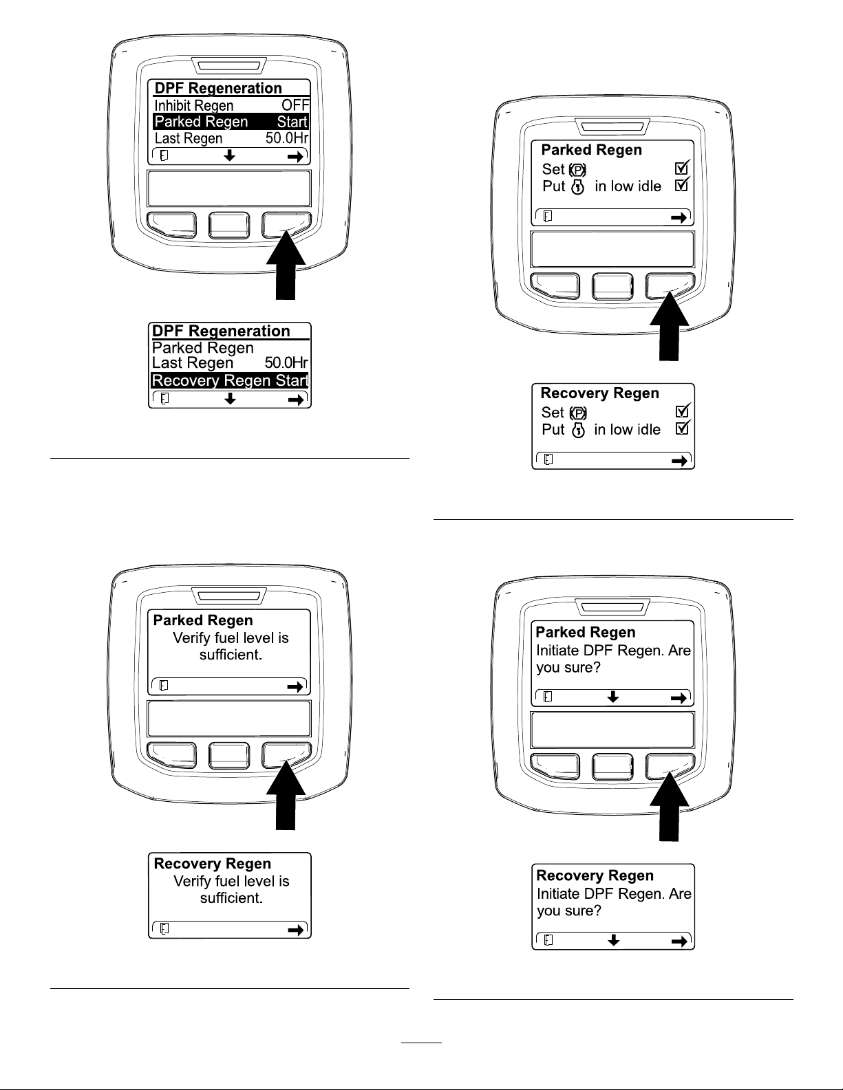
Figure43
3.AttheDPFchecklistscreen,verifythatthe
parkingbrakeisengagedandthattheengine
speedissettolowidle(Figure45).
g224402
g224407
g224629
2.AttheVERIFYFUELLEVELscreen,verifythatyou
have1/4tankoffuelifyouareperformingthe
parkedregenerationor1/2tankoffuelifyouare
performingtherecoveryregeneration,andpress
therightbuttontocontinue(Figure44).
g227679
Figure45
4.AttheINITIATEDPFREGENscreen,pressthe
rightbuttontocontinue(Figure46).
g224414
g224626
Figure44
g227678
g224630
Figure46
39

5.TheInfoCenterdisplaystheINITIA TINGDPF
REGENmessage(Figure47).
Figure47
6.TheInfoCenterdisplaysthetimetocomplete
message(Figure48).
CheckMessageandCorrectiveActionTable
(cont'd.)
g224411
CorrectiveAction:Startandruntheengine.
g227681
CorrectiveAction:Runtheenginetowarmthecoolant
temperatureto60°C(140°F).
Figure48
7.Theenginecomputercheckstheenginestate
andfaultinformation.TheInfoCentermay
displaythefollowingmessagesfoundinthe
tablethatfollows:
CheckMessageandCorrectiveActionT able
CorrectiveAction:Exittheregenerationmenuandrunthe
machineuntilthetimesincelastregenerationisgreaterthan
50hours;refertoTimeSinceLastRegeneration(page33).
g224406
g224406
CorrectiveAction:Changetheenginespeedtolowidle.
CorrectiveAction:Troubleshoottheenginecomputer
conditionandretryDPFregeneration.
8.TheInfoCenterdisplaysthehomescreenand
theregenerationacknowledgeicon(Figure49)
appearsinthelowerrightcornerofthescreen
astheregenerationprocesses.
g224403
Figure49
CorrectiveAction:Troubleshoottheenginefaultandretry
DPFregeneration.
Note:WhiletheDPFregeneration
runs,theInfoCenterdisplaysthehigh
exhaust-temperatureicon.
9.Whentheenginecomputercompletesa
parkedorrecoveryregeneration,theInfoCenter
40
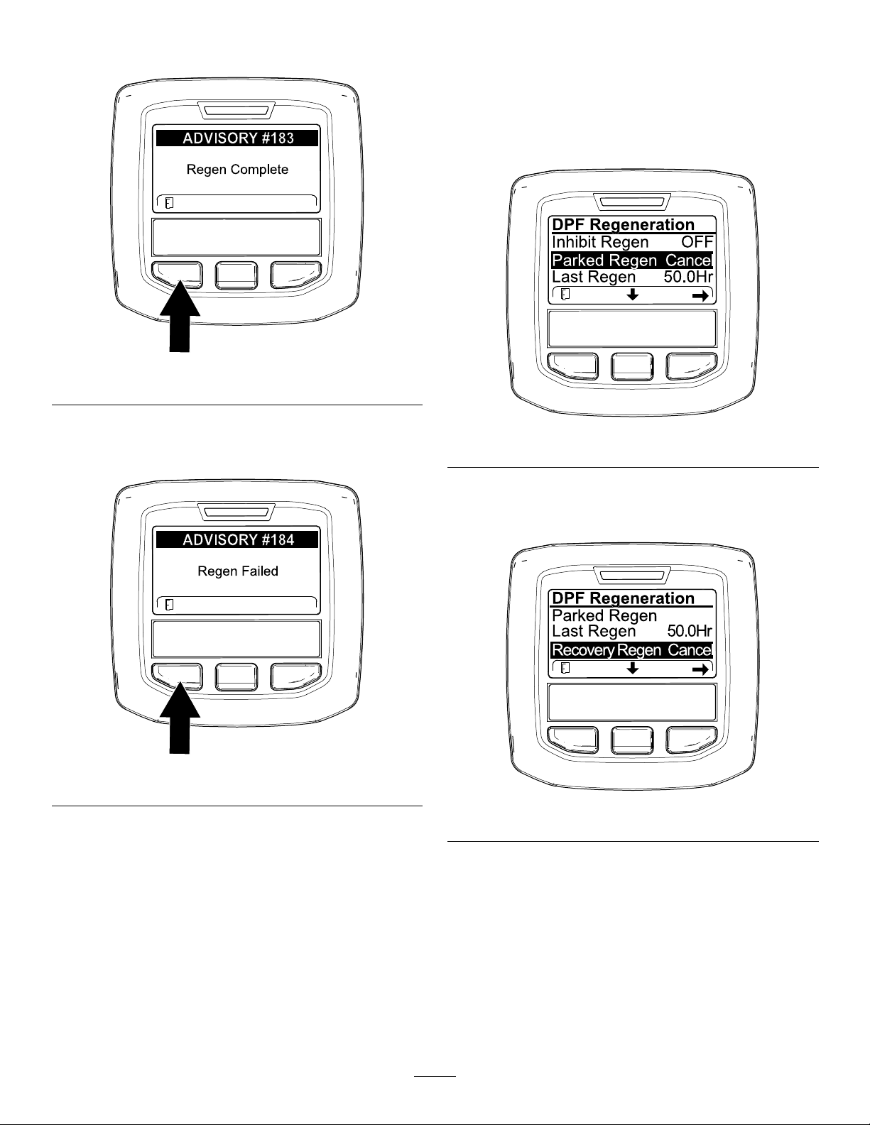
displaysADVISORY#183(Figure50).Pressthe
leftbuttontoexittothehomescreen.
Figure50
CancelingaParkedorRecoveryRegeneration
UsetheParkedRegenCancelorRecoveryRegen
Cancelsettingtocancelarunningparkedorrecovery
regenerationprocess.
1.AccesstheDPFRegenerationmenu(Figure
52).
g224392
Note:Iftheregenerationfailstocomplete,the
InfoCenterdisplaysAdvisory#184(Figure50).
Presstheleftbuttontoexittothehomescreen.
Figure51
g227305
Figure52
2.Pressthecenterbuttontoscrolldowntothe
PARKEDREGENCANCEL(Figure52)orthe
RECOVERYREGENCANCELoption(Figure53).
g224393
g227306
Figure53
3.PresstherightbuttontoselecttheRegen
Cancelentry(Figure52orFigure53).
41

OperatingTips
buildupinmowerhousing,cuttingperformancewill
decrease.
BecomingFamiliarizedwiththe
Machine
Beforemowinggrass,practiceoperatingthemachine
inanopenarea.Startandshutofftheengine.
Operateinforwardandreverse.Lowerandraisethe
cuttingdecksandengageanddisengagethemowers.
Whenyoufeelfamiliarwiththemachine,practice
operatingupanddownslopesatdifferentspeeds.
SelectingtheProperHeight-of-Cut
SettingtoSuitConditions
Removenomorethanapproximately25mm(1inch),
or1/3ofthegrassbladewhencutting.Inexceptionally
lushanddensegrass,youmayneedtoraiseyour
height-of-cutsetting.
Mowing
TurnthekeyintheignitionswitchtotheONposition,
starttheengine,andmovethethrottletotheFAST
position.MovetheEnable/Disableswitchtothe
ENABLEpositionandusetheLowerMow/Raiselever
tocontrolthecuttingdecks.T omoveforwardandcut
grass,pressthetractionpedalforward.
TransportingtheMachine
MovetheEnable/DisableswitchtotheDISABLE
positionandraisethecuttingunitstotheTRANSPORT
position.MovetheMow/Transportlevertothe
TRANSPORTposition.Becarefulwhendrivingbetween
objectssoyoudonotaccidentallydamagethe
machineorcuttingunits.Useextracarewhen
operatingthemachineonslopes;refertoSlope
Safety(page28).
Note:Allowtheenginetoidlefor5minutesbefore
shuttingitoffafterafullloadoperation.Failuretodo
somayleadtoturbo-chargertrouble.
MowingwithSharpBlades
Asharpbladecutscleanlyandwithouttearingor
shreddingthegrassblades.Adullblade,whichtears
andshredsgrass,causesgrasstoturnbrownat
theedges.Thisimpairsgrassgrowthandincreases
susceptibilitytodiseases.Ensurethatthebladeisin
goodconditionandthatthereisafullsail.
CheckingtheCutting-Unit
Condition
Ensurethatthechambersofeachcuttingunitarein
goodcondition.Straightenanychamber-component
bendstoensurethecorrectbladetip/chamber
clearance.
CheckingtheMowerHousing
AfterOperating
Toensurethatoptimumperformanceismet,cleanthe
undersideofmowerhousing.Ifyouallowresidueto
42

AfterOperation
AfterOperationSafety
•Cleangrassanddebrisfromthecuttingunits,
mufers,andenginecompartmenttohelpprevent
res.Cleanupoilorfuelspills.
•Ifthecuttingunitsareinthetransportposition,use
thepositivemechanicallock(ifavailable)before
youleavethemachineunattended.
•Allowtheenginetocoolbeforestoringthemachine
inanyenclosure.
•Removethekeyandshutoffthefuel(ifequipped)
beforestoringortransportingthemachine.
•Neverstorethemachineorfuelcontainerwhere
thereisanopename,spark,orpilotlight,such
asonawaterheateroronotherappliances.
•Keepallpartsofthemachineingoodworking
conditionandallhardwaretightened,especially
blade-attachmenthardware.
•Maintainandcleantheseatbelt(s)asnecessary
•Replaceallwornordamageddecals.
IdentifyingtheTie-Down Points
•Frontofthemachine—theholeintherectangular
pad,undertheaxletube,insideeachfronttire
(Figure54).
g004555
Figure55
1.Reartie-down
HaulingtheMachine
•Removethekeyandshutoffthefuel(ifequipped)
beforestoringortransportingthemachine.
•Usecarewhenloadingorunloadingthemachine
intoatraileroratruck.
•Usefull-widthrampsforloadingthemachineinto
atraileroratruck.
•Tiethemachinedownsecurely.
Figure54
1.Fronttie-down
•Rearofthemachine—eachside
ofthemachineontherearframe
(Figure55).
g031851
43
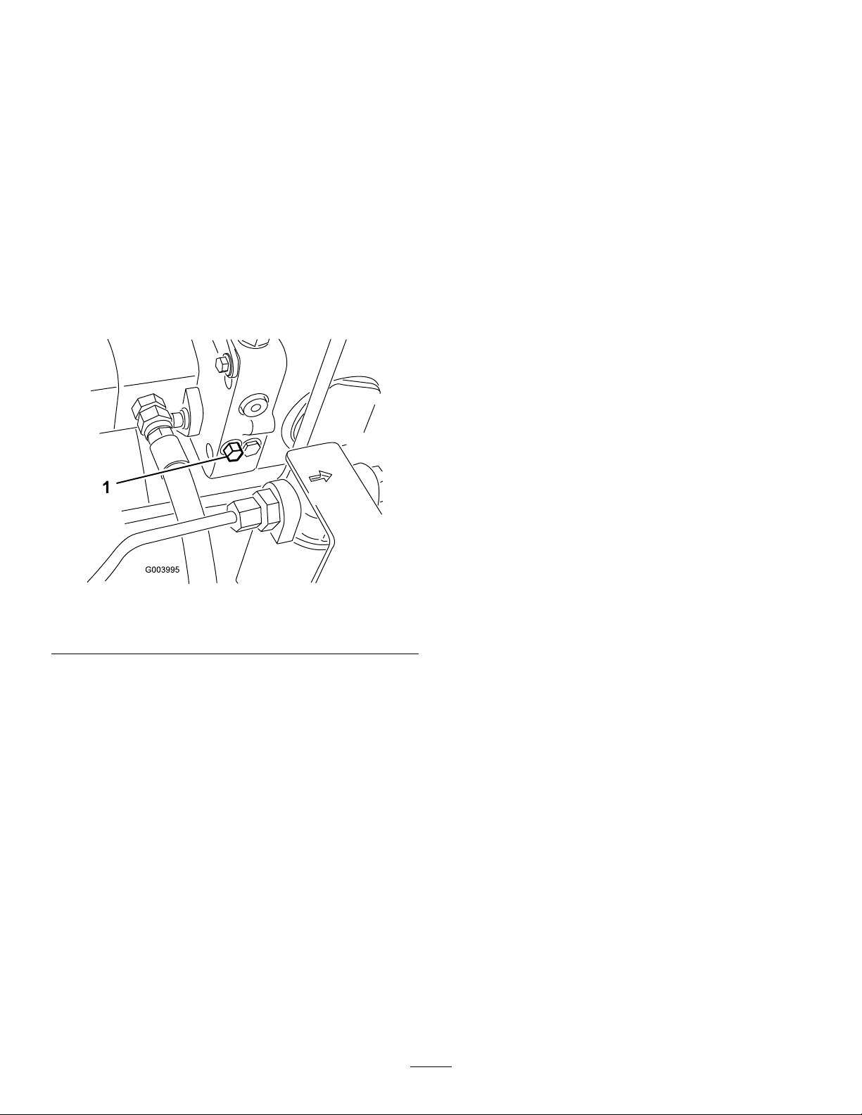
PushingorTowingthe Machine
Inanemergency,youcanmovethemachine
forwardbyactuatingthebypassvalveinthe
variable-displacementhydraulicpumpandpushingor
towingthemachine.
Important:Donotpushortowthemachinefaster
than3to4.8km/h(2to3mph).Ifyoupushortow
atafasterspeed,internaltransmissiondamage
mayoccur.
Thebypassvalvesmustbeopenwheneveryou
pushortowthemachine.
1.Locatethebypassvalveontheleftsideofthe
hydrostat(Figure56).
Figure56
1.Bypassvalve
2.Loosenthebolt1-1/2turnstoallowtheoilto
bypassinternally.
Note:Becausetheuidisbypassed,the
machinecanbemovedslowlywithoutdamaging
thetransmission.
3.Pushortowthemachine.
4.Finishpushingortowingthemachineandclose
thebypassvalve.Torquethevalveto11N∙m
(5to8ft-lb).
Important:Ensurethatthebypassvalveis
closedbeforeyoustarttheengine.Running
theenginewithanopenbypassvalvecauses
thetransmissiontooverheat.
g003995
44

Maintenance
Note:Determinetheleftandrightsidesofthemachinefromthenormaloperatingposition.
Important:Refertoyourengineowner’smanualforadditionalmaintenanceprocedures.
Important:Ifyouareperformingmaintenanceonthemachineandruntheenginewithanengine
exhaust-extractionduct,settheinhibitregensettingtoON;refertoSettingtheInhibitRegen(page35).
RecommendedMaintenanceSchedule(s)
MaintenanceService
Interval
Afterthersthour
Aftertherst10hours
Aftertherst50hours
Beforeeachuseordaily
Every50hours
Every100hours
Every250hours
MaintenanceProcedure
•T orquethewheel-lugnutsto94to122N∙m(70to90ft-lb).
•T orquethewheel-lugnutsto94to122N∙m(70to90ft-lb).
•Changetheengineoilandlter.
•Checkthetirepressure.
•Checktheoperationofthesafety-interlockswitches.
•Checktheengine-oillevel.
•Checkthelevelofcoolantintheexpansiontankandcleandebrisoffthescreen,oil
cooler,andfrontoftheradiator.
•Removedebrisfromthescreen,oilcoolers,andradiator(morefrequentlyindirty
operatingconditions).
•Checkthehydraulicuidlevel.
•Checkthehydrauliclinesandhosesforleaks,kinkedlines,loosemountingsupports,
wear,loosettings,weatherdeterioration,andchemicaldeterioration.
•Greasethebearingsandbushings(immediatelyaftereverywashingregardlessof
theintervallisted).
•Checktheconditionofandcleanthebattery.
•Checkthebatterycableconnections.
•Inspectthecooling-systemhoses.
•Checktheconditionandtensionofthealternatorbelt.
•T orquethewheel-lugnutsto94to122N∙m(70to90ft-lb).
•Changetheengineoilandlter.
Every400hours
Every800hours
Every6,000hours
Beforestorage
Every2years
•Servicetheaircleaner.(Orearlieriftheair-cleanerindicatorilluminatesred.Service
itmorefrequentlyinextremelydirtyordustyconditions.)
•Replacethefuellter.
•Checkthefuellinesandconnectionsfordeterioration,damage,orlooseconnections
(oryearly,whichevercomesrst).
•Replacethefuelltercanister.
•Drainandcleanthefueltank.
•Checktherearwheeltoe-in.
•Changethehydraulicuid.
•Changethehydrauliclters(sooneriftheserviceintervalindicatorisintheredzone).
•Packtherear-wheelbearings.
•Disassemble,clean,andassemblethesootlteroftheDPForcleanthesootlter
ifenginefaultsSPN3251FMI0,SPN3720FMI0,orSPN3720FMI16displayinthe
InfoCenter.
•Drainandcleanthefueltank.
•Flushandreplacethecooling-systemuid.
•Drainandushthehydraulictank.
•Replaceallmovinghoses.
45

DailyMaintenanceChecklist
Duplicatethispageforroutineuse.
Fortheweekof:
MaintenanceCheckItem
Checkthesafety-interlockoperation.
Checkthebrakeoperation.
Checktheengineoilandfuellevel.
Drainthewater/fuelseparator.
Checktheair-lter-restrictionindicator.
Checktheradiatorandscreenfordebris.
Checkunusualenginenoises.
Checkunusualoperatingnoises.
Checkthehydraulicsystemuidlevel.
Checkthehydraulic-lterindicator.
Checkhydraulichosesfordamage.
Checkforuidleaks.
Checkthetirepressure.
Checktheinstrumentoperation.
Checktheheight-of-cutadjustment
Checktheconditionoftheblades
Checkallgreasettingsforlubrication
Touch-updamagedpaint.
1.Checktheglowplugandinjectornozzlesifhardstarting,excesssmoke,orroughrunningisnoted.
1
2
3
Mon.Tues.Wed.Thurs.Fri.
Sat.Sun.
2.Checkwiththeenginerunningandtheoilatoperatingtemperature
3.Immediatelyaftereverywashing,regardlessoftheintervallisted
NotationforAreasofConcern
Inspectionperformedby:
ItemDate
1
2
3
4
5
6
7
8
Note:Downloadafreecopyoftheelectricalorhydraulicschematicbyvisitingwww.T oro.comandsearching
foryourmachinefromtheManualslinkonthehomepage.
Information
46
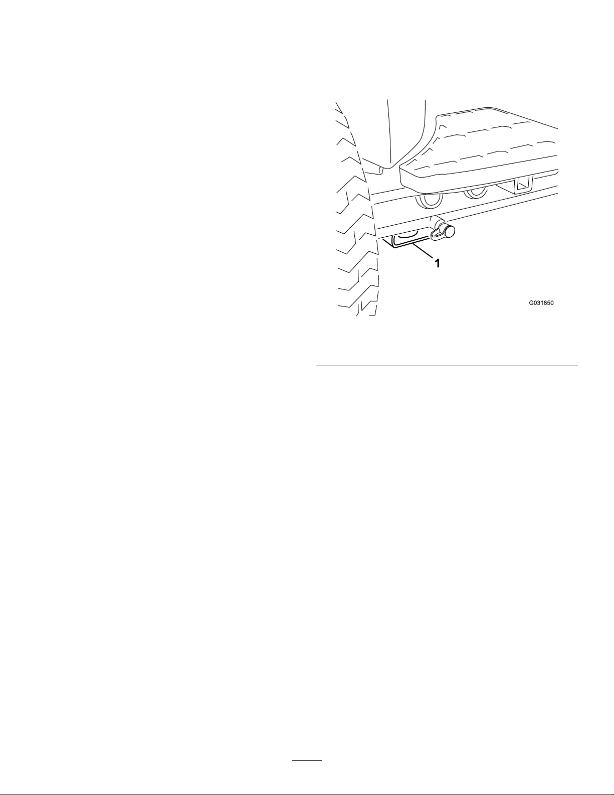
Pre-Maintenance
RaisingtheMachine
Procedures
MaintenanceSafety
•Beforeadjusting,cleaning,repairing,orleaving
themachine,dothefollowing:
–Parkthemachineonalevelsurface.
–Movethethrottleswitchtothelow-idleposition.
–Disengagethecuttingunits.
–Lowerthecuttingunits.
–Ensurethatthetractionisinneutral.
–Engagetheparkingbrake.
–Shutofftheengineandremovethekey.
–Waitforallmovingpartstostop.
–Allowmachinecomponentstocoolbefore
performingmaintenance.
•Ifthecuttingunitsareinthetransportposition,use
thepositivemechanicallock(ifavailable)before
youleavethemachineunattended.
•Ifpossible,donotperformmaintenancewhilethe
engineisrunning.Keepawayfrommovingparts.
•Usejackstandstosupportthemachineor
componentswhenrequired.
Usethefollowingaspointstojackupthemachine:
•Frontofthemachine—rectangularpad,under
theaxletube,insideeachfronttire(Figure57).
g031850
Figure57
1.Frontjackingpoint
•Rearofthemachine—rectangularaxletubeon
therearaxle.
•Carefullyreleasepressurefromcomponentswith
storedenergy.
47

Lubrication
GreasingtheBearingsand Bushings
Ifyouoperatethemachineundernormalconditions,
useNo.2lithiumgreasetolubricateallbearings
andbushingsatthespeciedmaintenanceinterval.
Lubricatebearingsandbushingsimmediatelyafter
everywashing,regardlessoftheintervallisted.
Thegreasettinglocationsandquantitiesareas
follows:
•PumpdriveshaftU-joint(3)—Figure58
•Cuttingunitcarrier-framepivot(1each)—Figure
60
g011613
Figure60
•Lift-armpivotshaft(1each)—Figure61
Figure58
•Cuttingunitlift-armcylinders(2each)—Figure59
Figure59
•Lift-armpivots(1each)—Figure59
g003962
g004157
Figure61
•Rearaxletierod(2)—Figure62
g011612
g003987
Figure62
48

•Axle-steeringpivot(1)—Figure63
Figure63
•Steering-cylinderballjoints(2)andrearaxle
(1)—Figure64
•Cuttingunitspindle-shaftbearings(2percutting
unit)—Figure66
Note:Youcanuseeithertting,whicheveris
moreaccessible.Pumpgreaseintothettinguntil
asmallamountappearsatbottomofthespindle
housing(underthecuttingunit).
g004169
g008906
Figure66
•Rear-rollerbearings(2percuttingunit)—Figure67
Figure64
•Brakepedal(1)—Figure65
Figure65
g008907
Figure67
g011614
Note:Ensurethatthegreasegrooveineach
rollermountalignswiththegreaseholeineach
endoftherollershaft.T ohelpalignthegroove
andhole,thereisalsoanalignmentmarkon1end
oftherollershaft.
g011615
49

EngineMaintenance
EngineSafety
•Shutofftheengineandremovethekeybefore
checkingtheoiloraddingoiltothecrankcase.
•Donotchangethegovernorspeedoroverspeed
theengine.
ServicingtheAirCleaner
Checkthewholeintakesystemforleaks,damage,or
loosehoseclamps.Donotuseadamagedairlter.
Servicetheair-cleanerlteronlywhentheservice
indicatorrequiresit.Changingtheairlterbeforeitis
necessaryonlyincreasesthechanceofdirtentering
theenginewhenthelterisremoved.
Important:Makesurethatthecoverisseated
correctly,sealswiththeair-cleanerbody,
andtherubberoutletvalveisinadownward
position—betweenthe5o’clockand7o’clock
positionswhenviewedfromtheend.
g194209
g031351
Figure68
50

ServicingtheEngineOil
OilSpecication
Usehigh-quality,low-ashengineoilthatmeetsor
exceedsthefollowingspecications:
•APIservicecategoryCJ-4orhigher
•ACEAservicecategoryE6
•JASOservicecategoryDH-2
Important:UsingengineoilotherthanAPICJ-4
orhigher,ACEAE6,orJASODH-2maycausethe
dieselparticulateltertoplugorcauseengine
damage.
Usethefollowingengineoilviscositygrade:
•Preferredoil:SAE15W-40(above0°F)
•Alternateoil:SAE10W-30or5W-30(all
temperatures)
ToroPremiumEngineOilisavailablefromyour
authorizedTorodistributorineither15W-40or10W-30
viscositygrades.SeethePartsCatalogforpart
numbers.
g194204
CheckingtheEngine-OilLevel
ServiceInterval:Beforeeachuseordaily
Theengineisshippedwithoilinthecrankcase;
however,theoillevelmustbecheckedbeforeand
aftertheengineisrststarted.
Important:Checktheengineoildaily.Ifthe
engine-oillevelisabovetheFullmarkonthe
dipstick,theengineoilmaybedilutedwithfuel;
IftheengineoillevelisabovetheFullmark,
changetheengineoil.
Thebesttimetochecktheengineoiliswhenthe
engineiscoolbeforeithasbeenstartedfortheday.
Ifithasalreadybeenrun,allowtheoiltodrainback
downtothesumpforatleast10minutesbefore
checking.IftheoillevelisatorbelowtheAddmark
onthedipstick,addoiltobringtheoilleveltotheFull
mark.Donotoverlltheenginewithoil.
Important:Keeptheengineoillevelbetweenthe
upperandlowerlimitsonthedipstick;theengine
mayfailifyourunitwithtoomuchortoolittleoil.
1.Parkthemachineonalevelsurface.
2.Checktheengine-oillevel(Figure69).
g031256
Figure69
Note:Whenusingdifferentoil,drainalloldoil
fromthecrankcasebeforeaddingnewoil.
CrankcaseOilCapacity
Approximately5.2L(5.5USqt)withthelter.
ChangingtheEngineOilandFilter
ServiceInterval:Aftertherst50hours
Every250hours
1.Starttheengineandletitrun5minutestoallow
theoiltowarmup.
2.Withthemachineparkedonalevelsurface,
shutofftheengine,removethekey ,andwait
forallmovingpartstostopbeforeleavingthe
operatingposition.
3.Replacetheengineoilandlter(Figure70).
51

Servicingthe Diesel-OxidationCatalyst (DOC)andtheSootFilter
ServiceInterval:Every6,000hours—Disassemble,
clean,andassemblethesootlter
oftheDPForcleanthesootlterif
g194203
IfenginefaultsCHECKENGINESPN3251FMI0,CHECK
ENGINESPN3720FMI0,orCHECKENGINESPN3720
FMI16displayintheInfoCenter(Figure71),cleanthe
sootlterusingthestepsthatfollow:
enginefaultsSPN3251FMI0,SPN
3720FMI0,orSPN3720FMI16
displayintheInfoCenter.
g214715
4.Addoiltothecrankcase.
Figure70
g213864
g213863
Figure71
g031400
1.RefertotheEnginesectionintheService
Manualforinformationondisassemblingand
assemblingthediesel-oxidationcatalystandthe
sootlteroftheDPF .
2.RefertoyourauthorizedT orodistributorfor
diesel-oxidationcatalystandthesootlter
replacementpartsorservice.
3.ContactyourauthorizedT orodistributortoreset
theengineECUafteryouinstallacleanDPF .
52

FuelSystem
Maintenance
ServicingtheFuelFilter
ServiceInterval:Every400hours—Replacethefuel
lter.
1.Cleantheareaaroundthefuel-lterhead
(Figure72).
CheckingtheFuelLinesand Connections
Inspectthemfordeterioration,damage,orloose
connections.
Figure72
1.Fuel-lterhead2.Fuellter
2.Removethelterandcleanthelterhead
mountingsurface(Figure72).
3.Lubricatetheltergasketwithcleanlubricating
engineoil.RefertotheEngineOperator's
Manualforadditionalinformation.
4.Installthedryltercanisterbyhand,untilthe
gasketcontactsthelterhead,thenrotateitan
additional1/2turn.
5.Starttheengineandcheckforfuelleaksaround
thelterhead.
ServicingtheFuelSystem
DrainingtheFuelTank
ServiceInterval:Every800hours
g021576
Beforestorage
Drainandcleanthefueltankifthefuelsystem
becomescontaminatedorifthemachineistobe
storedforanextendedperiod.Usecleanfueltoush
outthetank.
53

ServicingtheWater
ServicingtheFuel-Pickup
Separator
ServiceInterval:Every400hours
Tube
Thefuel-pickuptube,locatedinsidethefueltank,is
equippedwithascreentohelppreventdebrisfrom
enteringthefuelsystem.Removethefuel-pickuptube
andcleanscreenasrequired.
g194210
Figure73
g031412
54

ElectricalSystem
Maintenance
ElectricalSystemSafety
•Disconnectthebatterybeforerepairingthe
machine.Disconnectthenegativeterminalrst
andthepositivelast.Connectthepositiveterminal
rstandthenegativelast.
•Chargethebatteryinanopen,well-ventilated
area,awayfromsparksandames.Unplugthe
chargerbeforeconnectingordisconnectingthe
battery.Wearprotectiveclothinganduseinsulated
tools.
ServicingtheBattery
Afterevery50hoursofoperation,performthe
followingtaskstoservicethebattery:
•Checkthebatterycondition
•Cleanthebattery(ifnecessary)
Note:T ocleanthebattery,washtheentirecase
withasolutionofbakingsodaandwater.Rinse
itwithclearwater.
•Checkthebattery-cableconnections
decal117-0169
Figure75
1.ReadtheOperator'sManual.
2.Powerpoint(10A)
3.Headlights(10A)
4.Power(10A)
5.Enginestart(15A)
6.Optionalairrideseatsuspension(20A)
7.EnginecomputermanagementC(7.5A)
8.EnginecomputermanagementB(7.5A)
9.EnginecomputermanagementA(7.5A)
LocatingtheFuses
Thereare8fusesintheelectricalsystem.The
fuseblock(Figure74)islocatedbehindthe
control-arm-accesspanel.RefertoFigure75fora
descriptionofeachfuse.
Figure74
1.Fuseblock
g021219
55

DriveSystem
Maintenance
4.TurnthekeyintheswitchtotheONposition,
starttheengine,androtatethecamhexineither
directionuntilthewheelsceaserotation.
5.Tightenthelocknuttosecuretheadjustment.
AdjustingtheTraction DriveforNeutral
Themachinemustnotcreepwhenthetractionpedal
isreleased.Ifitdoescreep,adjustasfollows:
1.Parkthemachineonalevelsurface,shutoffthe
engine,andlowerthecuttingunitstotheground.
2.Jackupthemachineuntilallthetiresareoffthe
ground;refertoRaisingtheMachine(page47).
Supportthemachinewithjackstandstoprevent
itfromfallingaccidentally .
3.Ontherightsideofthehydrostat,loosenthe
locknutonthetraction-adjustmentcam(Figure
76).
6.TurnthekeyintheswitchtotheOFFposition,
removethejackstands,andlowerthemachine
totheground.
7.Testdrivethemachinetomakesurethatitdoes
notcreep.
AdjustingtheRearWheel Toe-in
1.Rotatethesteeringwheelsothattherear
wheelsarestraightahead.
2.Loosenthejamnutoneachendofthetierod
(Figure77).
Note:Theendofthetierodwiththeexternal
grooveisaleftthread.
Figure76
1.Locknut2.Traction-adjustmentcam
WARNING
Theenginemustberunningsothenal
adjustmentofthetractionadjustment
camcanbeperformed.Thiscouldcause
personalinjury.
Keepyourhands,feet,face,andother
bodypartsawayfromthemufer,other
hotpartsoftheengine,andanyrotating
parts.
g004136
Figure77
g004147
1.Wrenchslot3.Jamnut
2.Tierod
3.Usingthewrenchslot,rotatethetierod.
4.Measurethedistanceatthefrontandrearofthe
rearwheelsataxleheight.
Note:Thedistanceatthefrontoftherear
wheelsshouldbelessthan6mm(1/4inch)of
thedistancemeasuredattherearofthewheels.
5.Repeatprocedureasrequired.
56

CoolingSystem
Maintenance
CAUTION
Iftheenginehasbeenrunning,the
pressurized,hotcoolantcanescapeand
causeburns.
CoolingSystemSafety
•Swallowingenginecoolantcancausepoisoning;
keepoutofreachfromchildrenandpets.
•Dischargeofhot,pressurizedcoolantortouching
ahotradiatorandsurroundingpartscancause
severeburns.
–Alwaysallowtheenginetocoolatleast15
minutesbeforeremovingtheradiatorcap.
–Usearagwhenopeningtheradiatorcap,and
openthecapslowlytoallowsteamtoescape.
•Donotoperatethemachinewithoutthecovers
inplace.
•Keepyourngers,handsandclothingclearof
rotatingfananddrivebelt.
•Shutofftheengineandremovethekeybefore
performingmaintenance.
CheckingtheCooling System
•Donotopentheradiatorcapwhenthe
engineisrunning.
•Usearagwhenopeningtheradiatorcap,
andopenthecapslowlytoallowsteamto
escape.
1.Checkthelevelofcoolantintheexpansiontank
(Figure78).
Note:Thecoolantlevelshouldbebetweenthe
marksonthesideofthetank.
ServiceInterval:Beforeeachuseordaily—Check
thelevelofcoolantintheexpansion
tankandcleandebrisoffthescreen,
oilcooler,andfrontoftheradiator.
Thecoolingsystemislledwitha50/50solutionof
waterandpermanentethyleneglycolantifreeze.The
capacityofthecoolingsystemis9.5L(10USqt).
DANGER
Therotatingfansanddrivebeltscancause
personalinjury.
•Donotoperatethemachinewithoutthe
coversinplace.
•Keepyourngers,hands,andclothing
clearoftherotatingfananddrivebelt.
•Shutofftheengineandremovethekey
beforeperformingmaintenance.
g021866
Figure78
1.Expansiontank
2.Ifthecoolantlevelislow,removethe
expansion-tankcapandreplenishthesystem.
Donotoverll.
3.Installtheexpansion-tankcap.
RemovingDebrisfromthe CoolingSystem
1.TurnthekeyintheswitchtotheOFFposition
andremovethekey.
2.Thoroughlycleanalldebrisoutoftheengine
area.
3.Unlatchtheclampandpivotopentherear
screen(Figure79).
57

Figure79
6.Thoroughlycleanbothsidesoftheoilcoolerand
theradiator(Figure81)withcompressedair.
g004138
1.Rear-screenlatch2.Rearscreen
4.Cleanthescreenthoroughlywithcompressed
air.
5.Pivotthelatchesinwardtoreleasetheoilcooler
(Figure80).
g004137
Figure81
1.Radiator
7.Pivottheoilcoolerbackintopositionandsecure
thelatches.
8.Closethescreenandsecurethelatch.
Figure80
1.Oil-coolerlatches2.Oilcooler
g003974
58

BrakeMaintenance
thatthecableconduitdoesnotrotateduring
tighteningprocedure.
AdjustingtheParking Brakes
Adjustthebrakeswhenthereismorethan2.5cm(1
inch)offreetravel(Figure82)ofthebrakepedal,or
whenmoreholdingforceisrequired.Freetravelis
thedistancethebrakepedalmovesbeforeyoufeel
brakingresistance.
Figure82
1.Freetravel
Adjustingthe Parking-BrakeLatch
Iftheparkingbrakefailstoengageandlatch,an
adjustmenttothebrakepawlisrequired.
1.Loosenthe2screwssecuringtheparkingbrake
pawltotheframe(Figure84).
g026816
Note:Usethewheelmotorbacklashtorockthe
drumsbackandforthtoensurethatthedrumsare
freepriortoandafteradjustment.
1.Toreducefreetravelofthebrakepedals,tighten
thebrakesbylooseningthefrontnutonthe
threadedendofthebrakecable(Figure83).
Figure83
1.Brakecables2.Frontnuts
2.Tightentherearnuttomovethecablebackward
untilbrakepedalshave0.63to1.27cm(1/4to
1/2inch)offreetravel(Figure82),beforewheel
lockupisachieved.
g031690
Figure84
1.Brakecables3.Parkingbrakepawl
2.Brakedetent
2.Presstheparkingbrakepedalforwarduntilthe
brakedetentcompletelyengagesonthebrake
pawl(Figure84).
3.Tightenthe2screwslockingtheadjustment.
4.Pressthebrakepedaltodisengagetheparking
brake.
5.Checktheadjustmentandadjustasrequired.
g031689
4.Screws(2)
3.Tightenthefrontnuts,ensuringthatbothcables
actuatethebrakessimultaneously.Ensure
59
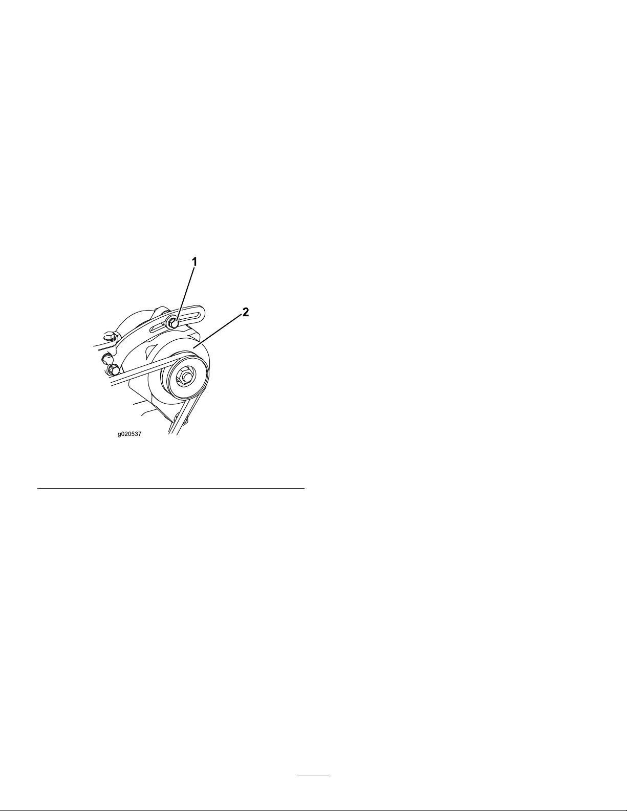
BeltMaintenance
ServicingtheAlternator
HydraulicSystem
Maintenance
Belt
ServiceInterval:Every100hours
Propertensionofthebeltallows10mm(3/8inch)of
deectionwhenaforceof4.5kg(10lb)isappliedon
thebeltmidwaybetweenthepulleys.
Ifthedeectionisnot10mm(3/8inch),loosenthe
alternator-mountingbolts(Figure85).
Note:Increaseordecreasethealternator-belt
tensionandtightenthebolts.Checkthedeectionof
thebeltagaintoensurethatthetensioniscorrect.
HydraulicSystemSafety
•Seekimmediatemedicalattentionifuidisinjected
intoskin.Injecteduidmustbesurgicallyremoved
withinafewhoursbyadoctor.
•Ensurethatallhydraulic-uidhosesandlinesare
ingoodconditionandallhydraulicconnections
andttingsaretightbeforeapplyingpressureto
thehydraulicsystem.
•Keepyourbodyandhandsawayfrompinhole
leaksornozzlesthatejecthigh-pressurehydraulic
uid.
•Usecardboardorpapertondhydraulicleaks.
•Safelyrelieveallpressureinthehydraulicsystem
beforeperforminganyworkonthehydraulic
system.
Checkingthe Hydraulic-FluidLevel
ServiceInterval:Beforeeachuseordaily
1.Mountingbolt2.Alternator
Figure85
Themachinesreservoirislledatthefactorywith
approximately56.7L(15USgallons)ofhighquality
hydraulicuid.Therecommendedreplacementuid
g020537
isasfollows:
ToroPremiumAllSeasonHydraulicFluid(Availablein
18.9L(5USgallon)pailsor208L(55USgallon)drums.
SeethePartsCatalogoryourToroDistributorforpart
numbers.)
Alternateuids:IftheT orouidisnotavailable,other
uidsmaybeusedprovidedtheymeetallthefollowing
materialpropertiesandindustryspecications.We
donotrecommendtheuseofsyntheticuid.Consult
withyourlubricantdistributortoidentifyasatisfactory
product.
Note:Useproductsonlyfromreputable
manufactures.Torodoesnottakeresponsibilityfor
damagecausedbyimpropersubstitutions.
HighViscosityIndex/LowPourPointAnti-wearHydraulic
Fluid,ISOVG46
MaterialProperties:
Viscosity,ASTMD445cSt@40°C44to48cSt
ViscosityIndexASTM
D2270
PourPoint,ASTMD97-34°Fto-49°F
@100°C7.9to8.5
140to160
60
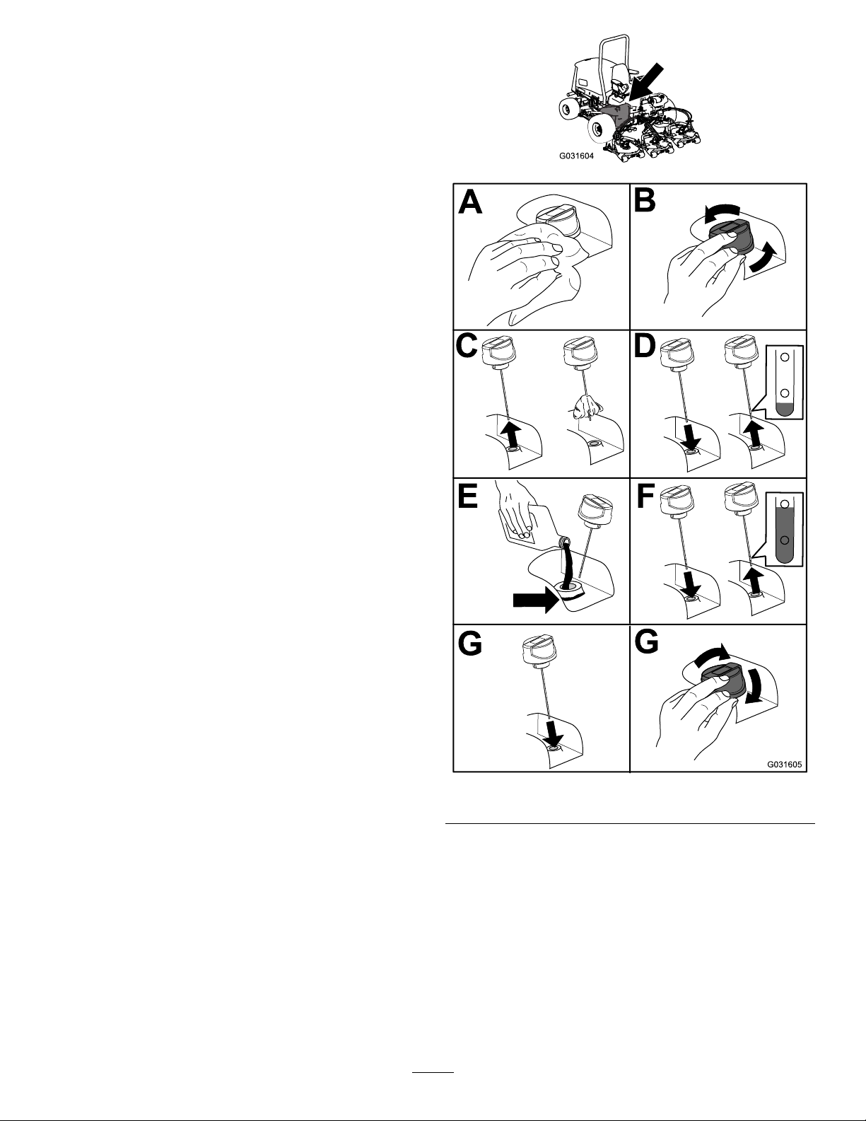
IndustrySpecications:
VickersI-286-S(QualityLevel),VickersM-2950-S
(QualityLevel),DenisonHF-0
Important:TheISOVG46Multigradeuid
hasbeenfoundtoofferoptimalperformance
inawide-rangeoftemperatureconditions.
Foroperationinconsistentlyhighambient
temperatures,18°C(65°F)to49°C(120°F),
ISOVG68hydraulicuidmayofferimproved
performance.
PremiumBiodegradableHydraulicFluid-Mobil
EALEnviroSyn46H
Important:MobilEALEnviroSyn46Histheonly
syntheticbiodegradableuidapprovedbyToro.
Thisuidiscompatiblewiththeelastomersused
inTorohydraulicsystemsandissuitablefora
wide-rangeoftemperatureconditions.Thisuidis
compatiblewithconventionalmineraloils,butfor
maximumbiodegradabilityandperformancethe
hydraulicsystemshouldbethoroughlyushedof
conventionaluid.Theoilisavailablein19L(5
USgallons)containersor208L(55USgallons)
drumsfromyourMobilDistributor.
g031604
Note:Manyhydraulicuidsarealmostcolorless,
makingitdifculttospotleaks.Areddyeadditivefor
thehydraulicsystemoilisavailablein20ml(2/3oz)
bottles.1bottleissufcientfor15to23L(4to6US
gallons)ofhydraulicoil.OrderPartNo.44-2500from
yourToroDistributor.
1.Positionthemachineonalevelsurface,lower
thecuttingdecks,andturnthekeyintheswitch
totheOFFposition.
2.Checkthehydraulic-uidlevel(Figure86).
g031605
Figure86
61
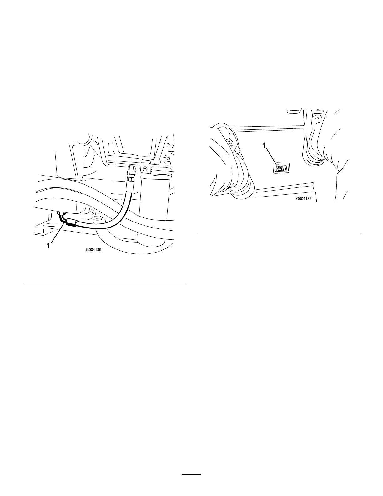
ChangingtheHydraulic Fluid
ServiceInterval:Every800hours
Ifuidbecomescontaminated,contactyourT oro
Distributorbecausethesystemmustbeushed.
Contaminateduidlooksmilkyorblackwhen
comparedtocleanoil.
1.TurnthekeyintheswitchtotheOFFposition
andraisethehood.
2.Placealargedrainpanunderthettingsecured
tothebottomofthehydraulic-uidreservoir
(Figure87).
Important:Donotoverll.
ReplacingtheHydraulic Filters
Thehydraulicsystemisequippedwitha
service-intervalindicator(Figure88).Withtheengine
running,viewtheindicator,itshouldbeinthegreen
zone.Whentheindicatorisintheredzone,change
thehydrauliclters.
Figure87
1.Hose
3.Disconnectthehosefromthebottomofthe
ttingandletthehydraulicuidowintothe
drainpan.
4.Installthehosewhenhydraulicuidstops
draining.
5.Fillthereservoirwithapproximately56.7L(15
USgallons)ofhydraulicuid;refertoChecking
theHydraulic-FluidLevel(page60).
Important:Useonlyhydraulicuids
specied.Otheruidscouldcausesystem
damage.
6.Installthereservoircap.
7.TurnthekeyintheswitchtotheONposition,
starttheengine,useallofthehydrauliccontrols
todistributehydraulicuidthroughoutthe
system,andcheckforleaks.
8.TurnthekeyintheswitchtotheOFFposition.
9.Checkthelevelofthehydraulicuidandadd
enoughtoraiseleveltotheFullmarkonthe
dipstick.
g004132
Figure88
1.Hydraulic-lterrestrictionindicator
Important:Useofanyotherltersmayvoidthe
g004139
warrantyonsomecomponents.
1.Positionthemachineonalevelsurface,lower
thecuttingdecks,turnthekeyintheswitchto
theOFFposition,engagetheparkingbrake,and
removethekey.
2.Replacebothofthehydrauliclters(Figure89).
62

CheckingtheHydraulic LinesandHoses
ServiceInterval:Beforeeachuseordaily
Makeallnecessaryrepairsbeforeoperating.
g031625
WARNING
Hydraulicuidescapingunderpressurecan
penetrateskinandcauseinjury.
•Makesurethatallhydraulic-uidhoses
andlinesareingoodconditionandall
hydraulicconnectionsandttingsaretight
beforeapplyingpressuretothehydraulic
system.
•Keepyourbodyandhandsawayfrom
pinholeleaksornozzlesthateject
high-pressurehydraulicuid.
•Usecardboardorpapertondhydraulic
leaks.
•Safelyrelieveallpressureinthehydraulic
systembeforeperforminganyworkonthe
hydraulicsystem.
Figure89
3.TurnthekeyintheswitchtotheONposition,
starttheengine,andletitrunforabout2minutes
topurgeairfromthesystem.
4.TurnthekeyintheswitchtotheOFFposition
andcheckforleaks.
•Getimmediatemedicalhelpifuidis
injectedintoskin.
g031621
Testingthe Hydraulic-SystemPressure
Usethehydraulicsystemtestportstotestthe
pressureinthehydrauliccircuits.Contactyour
authorizedT orodistributorforassistance.
HydraulicValveSolenoid Functions
Usethelistbelowtoidentifyanddescribethedifferent
functionsofthesolenoidsinthehydraulicmanifold.
Eachsolenoidmustbeenergizedtoallowfunction
tooccur.
Solenoid
PRV2Frontmowercircuit
PRV1Rearmowercircuit
PRV
S1
S2
Lift/lowercuttingdecks
Lowercuttingdecks
Lowercuttingdecks
Function
63

CuttingUnitMaintenance
MountingtheCuttingUnits totheTractionUnit
SeparatingtheCuttingUnit fromtheTractionUnit
1.Positionthemachineonalevelsurface,lower
thecuttingunitstotheoor,turnthekeyinthe
switchtotheOFFposition,andengagethe
parkingbrake.
2.Disconnectandremovethehydraulicmotor
fromthecuttingunit(Figure90).Coverthetop
ofthespindletopreventcontamination.
Figure90
1.Motor-mountingscrews
3.Removethelynchpinsecuringthedeck-carrier
frametothelift-armpivotpin(Figure91).
1.Positionthemachineonalevelsurfaceandturn
thekeyintheswitchtotheOFFposition.
2.Movethecuttingunitintopositioninfrontofthe
tractionunit.
3.Slidethedeck-carrierframeontothelift-arm
pivotpinandsecureitwiththelynchpin(Figure
91).
4.Installthehydraulicmotortothedeck(Figure
90).MakesurethattheO-ringisinpositionand
notdamaged.
5.Greasethespindle.
ServicingtheFrontRoller
Inspectthefrontrollerforwear,excesswobble,or
binding.Serviceorreplacetherollerorcomponentsif
anyoftheseconditionsexist.
g011351
DisassemblingtheFrontRoller
1.Removetheroller-mountingbolt(Figure92).
2.Insertapunchthroughtheendoftheroller
housinganddrivetheoppositebearingoutby
alternatingtapstotheoppositesideofinner
bearingrace.Thereshouldbea1.5mm(0.060
inch)lipofinnerraceexposed.
Figure91
1.Lynchpin
4.Rollthecuttingunitawayfromthetractionunit.
2.Lift-armpivotpin
g031691
1.Frontroller3.Bearing
2.Mountingbolt4.Bearingspacer
3.Pushthesecondbearingoutinpress.
4.Inspecttherollerhousing,bearings,andbearing
spacerfordamage(Figure92).Replaceany
damagedcomponentsandassemblethem.
64
Figure92
g011356

AssemblingtheFrontRoller
1.Presstherstbearingintotherollerhousing
(Figure92).Pressontheouterraceonlyor
equallyontheinnerandouterrace.
2.Insertthespacer(Figure92).
3.Pressthesecondbearingintotherollerhousing
(Figure92).Pressingequallyontheinnerand
outerraceuntiltheinnerracecomesincontact
withthespacer.
4.Installtherollerassemblyintothecutting-unit
frame.
5.Verifythatthereisnomorethana1.5mm(0.060
inch)gapbetweenrollerassemblyandtheroller
mountbracketsofthecutting-unitframe.Ifthere
isagapover1.5mm(0.060inch),installenough
5/8-inchdiameterwasherstotakeuptheslop.
BladeMaintenance
BladeSafety
Awornordamagedbladecanbreak,andapieceof
thebladecouldbethrowntowardyouorbystanders,
resultinginseriouspersonalinjuryordeath.
•Inspectthebladeperiodicallyforwearordamage.
•Usecarewhencheckingtheblades.Wrapthe
bladesorweargloves,andusecautionwhen
servicingtheblades.Onlyreplaceorsharpenthe
blades;neverstraightenorweldthem.
•Onmulti-bladedmachines,takecareasrotating1
bladecancauseotherbladestorotate.
ServicingtheBladePlane
Important:Securingtherollerassembly
withagaplargerthan1.5mm(0.060inch)
createsasideloadonthebearingandcan
leadtoprematurebearingfailure
6.Torquethemountingboltto108N∙m(80ft-lb).
Therotarydeckcomesfromthefactorypresetat5
cm(2inches)heightofcutandbladerakeof7.9mm
(0.310inch).Theleftandrightheightsarealsopreset
towithin±0.7mm(0.030inch)oftheother.
Thecuttingdeckisdesignedtowithstandblade
impactswithoutdeformationofthechamber.Ifasolid
objectisstruck,inspectthebladefordamageandthe
bladeplaneforaccuracy.
InspectingtheBladePlane
1.Removethehydraulicmotorfromthecutting
deckandremovethecuttingdeckfromthe
tractor.
2.Useahoist(orminimumof2people)andplace
thecuttingdeckonaattable.
3.Mark1endofthebladewithapaintpenor
marker.Usethisendofthebladetocheckall
heights.
4.Positionthecuttingedgeofthemarkedendof
thebladeat12o’clock(straightaheadinthe
directionofmowing)(Figure93)andmeasure
heightfromtabletocuttingedgeofblade.
g011353
Figure93
65

5.Rotatethemarkedendofthebladetothe3and
9o’clockpositions(Figure93)andmeasurethe
heights.
6.Comparethe12o’clockmeasuredheighttothe
height-of-cutsetting.Itshouldbewithin0.7mm
(0.030inch).The3and9o’clockheightsshould
be1.6to6.0mm(0.06to0.24inch)higherthan
the12o’clocksettingandwithin1.6to6.0mm
(0.06to0.24inch)ofeachother.
Note:Ifanyofthesemeasurementsarenotwithin
specication,proceedtoAdjustingtheBladePlane
(page66).
AdjustingtheBladePlane
Startwiththefrontadjustment(change1bracketata
time).
1.Removetheheight-of-cutbracket(front,left,or
right)fromthedeckframe(Figure94).
2.Adjust1.5mm(0.060inch)shimsand/or0.7mm
(0.030inch)shimbetweenthedeckframeand
brackettoachievethedesiredheightsetting
(Figure94).
the3or9o’clocksideis1.6to6.0mm(0.06to
0.24inch)higherthanthenewfrontheightthen
noadjustmentisneededforthatside.Adjustthe
othersidetowithin1.6to6.0mm(0.06to0.24
inch)ofthecorrectside.
7.Adjusttherightand/orleftheight-of-cutbrackets
byrepeatingsteps1through3.
8.Securethecarriageboltsandangenuts.
9.Again,verifythe12,3,and9o’clockheights.
Figure94
1.Height-of-cutbracket2.Shims
3.Installtheheight-of-cutbrackettothedeck
framewiththeremainingshimsassembled
belowtheheight-of-cutbracket.
4.Securethesocket-headbolt/spacerandange
nut.
Note:Socket-headbolt/spacerareheld
togetherwiththread-lockingadhesivetoprevent
thespacerfromfallinginsidethedeckframe.
5.Verifythe12o’clockheightandadjustifneeded.
6.Determineifonly1orboth(rightandleft)
height-of-cutbracketsneedtobeadjusted.If
g031692
66

RemovingandInstallinga
InspectingandSharpening
Blade
Replacethebladeifasolidobjectishit,thebladeis
outofbalance,orifthebladeisbent.Alwaysuse
genuineT ororeplacementbladestobesureofsafety
andoptimumperformance.Neverusereplacement
bladesmadebyothermanufacturersbecausethey
couldbedangerous.
1.Raisethecuttingdecktothehighestposition,
turnthekeyintheignitionswitchtotheOFF
position,andengagetheparkingbrake.Block
thecuttingdecktopreventitfromfalling
accidentally.
2.Grasptheendofthebladeusingaragorthickly
paddedglove.Removethebladebolt,anti-scalp
cup,andbladefromthespindleshaft(Figure
95).
theBlade
1.Raisethecuttingdecktothehighestposition,
turnthekeyintheignitionswitchtotheOFF
position,andengagetheparkingbrake.
2.Blockthecuttingdecktopreventitfromfalling
accidentally.
3.Examinethecuttingendsofthebladecarefully,
especiallywheretheatandcurvedpartsofthe
blademeet(Figure96).
Note:Sincesandandabrasivematerialcan
wearawaythemetalthatconnectstheat
andcurvedpartsoftheblade,checktheblade
beforeusingthemachine.
4.Ifwearisnoticed(Figure96),replacetheblade;
refertoRemovingandInstallingaBlade(page
67).
DANGER
Ifthebladeisallowedtowear,aslot
willformbetweenthesailandatpart
oftheblade(Figure95).Eventuallya
pieceoftheblademaybreakoffandbe
thrownfromunderthehousing,possibly
resultinginseriousinjurytoyourselfor
bystanders.
Figure95
1.Bladebolt2.Anti-scalpcup
3.Installtheblade,sailfacingtowardthecutting
deck,withtheanti-scalpcupandbladebolt
(Figure95).Tightenthebladeboltto115to149
N∙m(85to110ft-lb).
•Inspectthebladeperiodicallyforwear
g011355
ordamage.
•Alwaysreplaceawornordamaged
blade.
g006924
Figure96
1.Cuttingedge3.Wear/slot/crack
2.Sail
5.Inspectthecuttingedgesofallblades.Sharpen
thecuttingedgesiftheyaredullornicked.
Sharpenonlythetopofthecuttingedgeand
maintaintheoriginalcuttingangletomakesure
thatitissharp(Figure97).
67

6.Ifdullornicked,sharpenonlythetopcutting
edgewhilemaintainingtheoriginalcuttingangle
(Figure97).
Note:Thebladewillremainbalancedifthe
sameamountofmetalisremovedfromboth
cuttingedges.
Figure97
1.Sharpenatthisangleonly
7.Tocheckthebladeforbeingstraightand
parallel,laythebladeonalevelsurfaceand
checkitsends.
Note:Positiontheendsofthebladeslightly
lowerthanthecenter,andthecuttingedgelower
thantheheeloftheblade.Thisbladeproduces
agoodqualityofcutandrequiresminimalpower
fromtheengine.Bycontrastabladethatis
higherattheendsthanthecenter,orifcutting
edgeishigherthantheheel,thebladeisbentor
warpedandmustbereplaced.
8.Installtheblade,sailfacingtowardcuttingdeck,
withtheanti-scalpcupandbladebolt.T orque
thebladeboltto115to149N∙m(85to110ft-lb).
Storage
PreparingtheMachinefor Storage
PreparingtheTractionUnit
1.Thoroughlycleanthetractionunit,cuttingunits,
andengine.
2.Checkthetirepressure.Inatealltractionunit
g006926
tiresto83to103kPa(12to15psi).
3.Checkallfastenersforloosenessandtighten
themasnecessary.
4.Greaseallgreasettingsandpivotpoints.Wipe
upanyexcesslubricant.
5.Lightlysandandusetouch-uppaintonpainted
areasthatarescratched,chipped,orrusted.
Repairanydentsinthemetalbody.
6.Servicethebatteryandcablesasfollows:
A.Removethebatteryterminalsfromthe
batteryposts.
Note:Alwaysdisconnectthenegative
terminalrstandthepositivelast.Always
connectthepositiveterminalrstandthe
negativelast.
B.Cleanthebattery,terminals,andpostswith
awirebrushandbakingsodasolution.
C.Coatthecableterminalsandbatteryposts
withGrafo1 12Xskin-overgrease(Part
Number505-47)orpetroleumjellyto
preventcorrosion.
D.Slowlyrechargethebatteryevery60days
for24hourstopreventleadsulfationofthe
battery.
PreparingtheEngine
1.Draintheengineoilfromtheoilpanandreplace
thedrainplug.
2.Removeanddiscardtheoillter.Installanew
oillter.
3.Relltheoilpanwithdesignatedquantityof
motoroil.
4.TurnthekeyintheswitchtotheONposition,
starttheengine,andrunitatidlespeedfor
approximately2minutes.
5.TurnthekeyintheswitchtotheOFFposition.
6.Thoroughlydrainallfuelfromthefueltank,lines,
andthefuellter/waterseparatorassembly.
7.Flushthefueltankwithfresh,cleandieselfuel.
8.Secureallfuel-systemttings.
68

9.Thoroughlycleanandservicetheair-cleaner
assembly.
10.Sealtheair-cleanerinletandtheexhaustoutlet
withweatherprooftape.
11.Checktheantifreezeprotectionandaddas
neededforexpectedminimumtemperaturein
yourarea.
StoringtheCuttingUnits
Ifacuttingunitisseparatedfromthetractionunitfor
anylengthoftime,installaspindlepluginthetopof
thespindletoprotectthespindlefromdustandwater.
69

EuropeanPrivacyNotice
TheInformationT oroCollects
ToroWarrantyCompany(T oro)respectsyourprivacy .Inordertoprocessyourwarrantyclaimandcontactyouintheeventofaproductrecall,weaskyou
tosharecertainpersonalinformationwithus,eitherdirectlyorthroughyourlocalT orocompanyordealer .
TheT orowarrantysystemishostedonserverslocatedwithintheUnitedStateswhereprivacylawmaynotprovidethesameprotectionasapplies
inyourcountry.
BYSHARINGYOURPERSONALINFORMATIONWITHUS,YOUARECONSENTINGTOTHEPROCESSINGOFYOURPERSONALINFORMA TION
ASDESCRIBEDINTHISPRIV ACYNOTICE.
TheWayT oroUsesInformation
Toromayuseyourpersonalinformationtoprocesswarrantyclaims,tocontactyouintheeventofaproductrecallandforanyotherpurposewhichwetell
youabout.ToromayshareyourinformationwithT oro'safliates,dealersorotherbusinesspartnersinconnectionwithanyoftheseactivities.Wewillnot
sellyourpersonalinformationtoanyothercompany.Wereservetherighttodisclosepersonalinformationinordertocomplywithapplicablelawsand
withrequestsbytheappropriateauthorities,tooperateoursystemsproperlyorforourownprotectionorthatofotherusers.
RetentionofyourPersonalInformation
Wewillkeepyourpersonalinformationaslongasweneeditforthepurposesforwhichitwasoriginallycollectedorforotherlegitimatepurposes
(suchasregulatorycompliance),orasrequiredbyapplicablelaw .
Toro'sCommitmenttoSecurityofY ourPersonalInformation
Wetakereasonableprecautionsinordertoprotectthesecurityofyourpersonalinformation.Wealsotakestepstomaintaintheaccuracyandcurrent
statusofpersonalinformation.
AccessandCorrectionofyourPersonalInformation
Ifyouwouldliketorevieworcorrectyourpersonalinformation,pleasecontactusbyemailatlegal@toro.com.
AustralianConsumerLaw
AustraliancustomerswillnddetailsrelatingtotheAustralianConsumerLaweitherinsidetheboxoratyourlocalT oroDealer.
374-0282RevC

TheToroWarranty
ATwo-YearLimitedWarranty
ConditionsandProductsCovered
TheToroCompanyanditsafliate,ToroWarrantyCompany,pursuant
toanagreementbetweenthem,jointlywarrantyourT oroCommercial
product(“Product”)tobefreefromdefectsinmaterialsorworkmanship
fortwoyearsor1500operationalhours*,whicheveroccursrst.This
warrantyisapplicabletoallproductswiththeexceptionofAerators
(refertoseparatewarrantystatementsfortheseproducts).Wherea
warrantableconditionexists,wewillrepairtheProductatnocosttoyou
includingdiagnostics,labor,parts,andtransportation.Thiswarranty
beginsonthedatetheProductisdeliveredtotheoriginalretailpurchaser.
*Productequippedwithanhourmeter.
InstructionsforObtainingWarrantyService
YouareresponsiblefornotifyingtheCommercialProductsDistributoror
AuthorizedCommercialProductsDealerfromwhomyoupurchasedthe
Productassoonasyoubelieveawarrantableconditionexists.Ifyouneed
helplocatingaCommercialProductsDistributororAuthorizedDealer,or
ifyouhavequestionsregardingyourwarrantyrightsorresponsibilities,
youmaycontactusat:
ToroCommercialProductsServiceDepartment
ToroWarrantyCompany
811 1LyndaleAvenueSouth
Bloomington,MN55420-1196
952–888–8801or800–952–2740
E-mail:commercial.warranty@toro.com
OwnerResponsibilities
AstheProductowner,youareresponsibleforrequiredmaintenanceand
adjustmentsstatedinyourOperator'sManual.Failuretoperformrequired
maintenanceandadjustmentscanbegroundsfordisallowingawarranty
claim.
ItemsandConditionsNotCovered
Notallproductfailuresormalfunctionsthatoccurduringthewarranty
periodaredefectsinmaterialsorworkmanship.Thiswarrantydoesnot
coverthefollowing:
•Productfailureswhichresultfromtheuseofnon-Tororeplacement
parts,orfrominstallationanduseofadd-on,ormodiednon-Toro
brandedaccessoriesandproducts.Aseparatewarrantymaybe
providedbythemanufactureroftheseitems.
•Productfailureswhichresultfromfailuretoperformrecommended
maintenanceand/oradjustments.Failuretoproperlymaintainyour
ToroproductpertheRecommendedMaintenancelistedinthe
Operator’sManualcanresultinclaimsforwarrantybeingdenied.
•ProductfailureswhichresultfromoperatingtheProductinanabusive,
negligent,orrecklessmanner.
•Partssubjecttoconsumptionthroughuseunlessfoundtobedefective.
Examplesofpartswhichareconsumed,orusedup,duringnormal
Productoperationinclude,butarenotlimitedto,brakepadsand
linings,clutchlinings,blades,reels,rollersandbearings(sealedor
greasable),bedknives,sparkplugs,castorwheelsandbearings,tires,
lters,belts,andcertainsprayercomponentssuchasdiaphragms,
nozzles,andcheckvalves,etc.
•Failurescausedbyoutsideinuence.Conditionsconsideredtobe
outsideinuenceinclude,butarenotlimitedto,weather,storage
practices,contamination,useofunapprovedfuels,coolants,lubricants,
additives,fertilizers,water,orchemicals,etc.
•Failureorperformanceissuesduetotheuseoffuels(e.g.gasoline,
diesel,orbiodiesel)thatdonotconformtotheirrespectiveindustry
standards.
•Normalnoise,vibration,wearandtear,anddeterioration.
•Normal“wearandtear”includes,butisnotlimitedto,damagetoseats
duetowearorabrasion,wornpaintedsurfaces,scratcheddecalsor
windows,etc.
Parts
Partsscheduledforreplacementasrequiredmaintenancearewarranted
fortheperiodoftimeuptothescheduledreplacementtimeforthatpart.
Partsreplacedunderthiswarrantyarecoveredforthedurationofthe
originalproductwarrantyandbecomethepropertyofT oro.Torowillmake
thenaldecisionwhethertorepairanyexistingpartorassemblyorreplace
it.T oromayuseremanufacturedpartsforwarrantyrepairs.
DeepCycleandLithium-IonBatteryWarranty:
DeepcycleandLithium-Ionbatterieshaveaspeciedtotalnumberof
kilowatt-hourstheycandeliverduringtheirlifetime.Operating,recharging,
andmaintenancetechniquescanextendorreducetotalbatterylife.Asthe
batteriesinthisproductareconsumed,theamountofusefulworkbetween
chargingintervalswillslowlydecreaseuntilthebatteryiscompletelyworn
out.Replacementofwornoutbatteries,duetonormalconsumption,
istheresponsibilityoftheproductowner.Batteryreplacementmaybe
requiredduringthenormalproductwarrantyperiodatowner’sexpense.
Note:(Lithium-Ionbatteryonly):ALithium-Ionbatteryhasapartonly
proratedwarrantybeginningyear3throughyear5basedonthetime
inserviceandkilowatthoursused.RefertotheOperator'sManualfor
additionalinformation.
MaintenanceisatOwner’sExpense
Enginetune-up,lubrication,cleaningandpolishing,replacementoflters,
coolant,andcompletingrecommendedmaintenancearesomeofthe
normalservicesT oroproductsrequirethatareattheowner’sexpense.
GeneralConditions
RepairbyanAuthorizedToroDistributororDealerisyoursoleremedy
underthiswarranty.
NeitherTheToroCompanynorToroWarrantyCompanyisliablefor
indirect,incidentalorconsequentialdamagesinconnectionwiththe
useoftheToroProductscoveredbythiswarranty,includingany
costorexpenseofprovidingsubstituteequipmentorserviceduring
reasonableperiodsofmalfunctionornon-usependingcompletion
ofrepairsunderthiswarranty.ExceptfortheEmissionswarranty
referencedbelow,ifapplicable,thereisnootherexpresswarranty .All
impliedwarrantiesofmerchantabilityandtnessforusearelimitedto
thedurationofthisexpresswarranty.
Somestatesdonotallowexclusionsofincidentalorconsequential
damages,orlimitationsonhowlonganimpliedwarrantylasts,sotheabove
exclusionsandlimitationsmaynotapplytoyou.Thiswarrantygivesyou
speciclegalrights,andyoumayalsohaveotherrightswhichvaryfrom
statetostate.
Noteregardingenginewarranty:
TheEmissionsControlSystemonyourProductmaybecoveredby
aseparatewarrantymeetingrequirementsestablishedbytheU.S.
EnvironmentalProtectionAgency(EPA)and/ortheCaliforniaAirResources
Board(CARB).Thehourlimitationssetforthabovedonotapplytothe
EmissionsControlSystemWarranty.RefertotheEngineEmissionControl
WarrantyStatementsuppliedwithyourproductorcontainedintheengine
manufacturer’sdocumentationfordetails
CountriesOtherthantheUnitedStatesorCanada
CustomerswhohavepurchasedT oroproductsexportedfromtheUnitedStatesorCanadashouldcontacttheirT oroDistributor(Dealer)toobtain
guaranteepoliciesforyourcountry ,province,orstate.IfforanyreasonyouaredissatisedwithyourDistributor'sserviceorhavedifcultyobtaining
guaranteeinformation,contacttheT oroimporter.
374-0253RevD

CaliforniaProposition65WarningInformation
Whatisthiswarning?
Youmayseeaproductforsalethathasawarninglabellikethefollowing:
WARNING:CancerandReproductiveHarm—www.p65Warnings.ca.gov.
WhatisProp65?
Prop65appliestoanycompanyoperatinginCalifornia,sellingproductsinCalifornia,ormanufacturingproductsthatmaybesoldinorbroughtinto
California.ItmandatesthattheGovernorofCaliforniamaintainandpublishalistofchemicalsknowntocausecancer,birthdefects,and/orother
reproductiveharm.Thelist,whichisupdatedannually,includeshundredsofchemicalsfoundinmanyeverydayitems.ThepurposeofProp65isto
informthepublicaboutexposuretothesechemicals.
Prop65doesnotbanthesaleofproductscontainingthesechemicalsbutinsteadrequireswarningsonanyproduct,productpackaging,orliteraturewith
theproduct.Moreover,aProp65warningdoesnotmeanthataproductisinviolationofanyproductsafetystandardsorrequirements.Infact,the
CaliforniagovernmenthasclariedthataProp65warning“isnotthesameasaregulatorydecisionthataproductis‘safe’or‘unsafe.’”Manyofthese
chemicalshavebeenusedineverydayproductsforyearswithoutdocumentedharm.Formoreinformation,gotohttps://oag.ca.gov/prop65/faqs-view-all
AProp65warningmeansthatacompanyhaseither(1)evaluatedtheexposureandhasconcludedthatitexceedsthe“nosignicantrisklevel”;or(2)
haschosentoprovideawarningbasedonitsunderstandingaboutthepresenceofalistedchemicalwithoutattemptingtoevaluatetheexposure.
Doesthislawapplyeverywhere?
Prop65warningsarerequiredunderCalifornialawonly.ThesewarningsareseenthroughoutCaliforniainawiderangeofsettings,includingbutnot
limitedtorestaurants,grocerystores,hotels,schools,andhospitals,andonawidevarietyofproducts.Additionally,someonlineandmailorder
retailersprovideProp65warningsontheirwebsitesorincatalogs.
.
HowdotheCaliforniawarningscomparetofederallimits?
Prop65standardsareoftenmorestringentthanfederalandinternationalstandards.TherearevarioussubstancesthatrequireaProp65warning
atlevelsthatarefarlowerthanfederalactionlimits.Forexample,theProp65standardforwarningsforleadis0.5μg/day,whichiswellbelow
thefederalandinternationalstandards.
Whydon’tallsimilarproductscarrythewarning?
•ProductssoldinCaliforniarequireProp65labellingwhilesimilarproductssoldelsewheredonot.
•AcompanyinvolvedinaProp65lawsuitreachingasettlementmayberequiredtouseProp65warningsforitsproducts,butothercompanies
makingsimilarproductsmayhavenosuchrequirement.
•TheenforcementofProp65isinconsistent.
•CompaniesmayelectnottoprovidewarningsbecausetheyconcludethattheyarenotrequiredtodosounderProp65;alackofwarningsfora
productdoesnotmeanthattheproductisfreeoflistedchemicalsatsimilarlevels.
WhydoesToroincludethiswarning?
Torohaschosentoprovideconsumerswithasmuchinformationaspossiblesothattheycanmakeinformeddecisionsabouttheproductstheybuyand
use.T oroprovideswarningsincertaincasesbasedonitsknowledgeofthepresenceofoneormorelistedchemicalswithoutevaluatingthelevelof
exposure,asnotallthelistedchemicalsprovideexposurelimitrequirements.WhiletheexposurefromT oroproductsmaybenegligibleorwellwithinthe
“nosignicantrisk”range,outofanabundanceofcaution,T orohaselectedtoprovidetheProp65warnings.Moreover,ifT orodoesnotprovidethese
warnings,itcouldbesuedbytheStateofCaliforniaorbyprivatepartiesseekingtoenforceProp65andsubjecttosubstantialpenalties.
RevA
 Loading...