

Page 1

FormNo.3385-829RevA
Groundsmaster
®
4500-Dand
4700-DRotaryMower
ModelNo.30857N—SerialNo.314000001andUp
ModelNo.30858N—SerialNo.314000001andUp
Registeratwww.T oro.com.
OriginalInstructions(EN)
*3385-829*A
Page 2
WARNING
CALIFORNIA
Proposition65Warning
Thisproductcontainsachemicalorchemicals
knowntotheStateofCaliforniatocausecancer,
birthdefects,orreproductiveharm.
Dieselengineexhaustandsomeofits
constituentsareknowntotheStateof
Californiatocausecancer,birthdefects,
andotherreproductiveharm.
Becauseinsomeareastherearelocal,state,orfederal
regulationsrequiringthatasparkarresterbeusedonthe
engineofthismachine,asparkarresterisincorporatedwith
themuferassembly.
GenuineT orosparkarrestersareapprovedbytheUSDA
ForestryService.
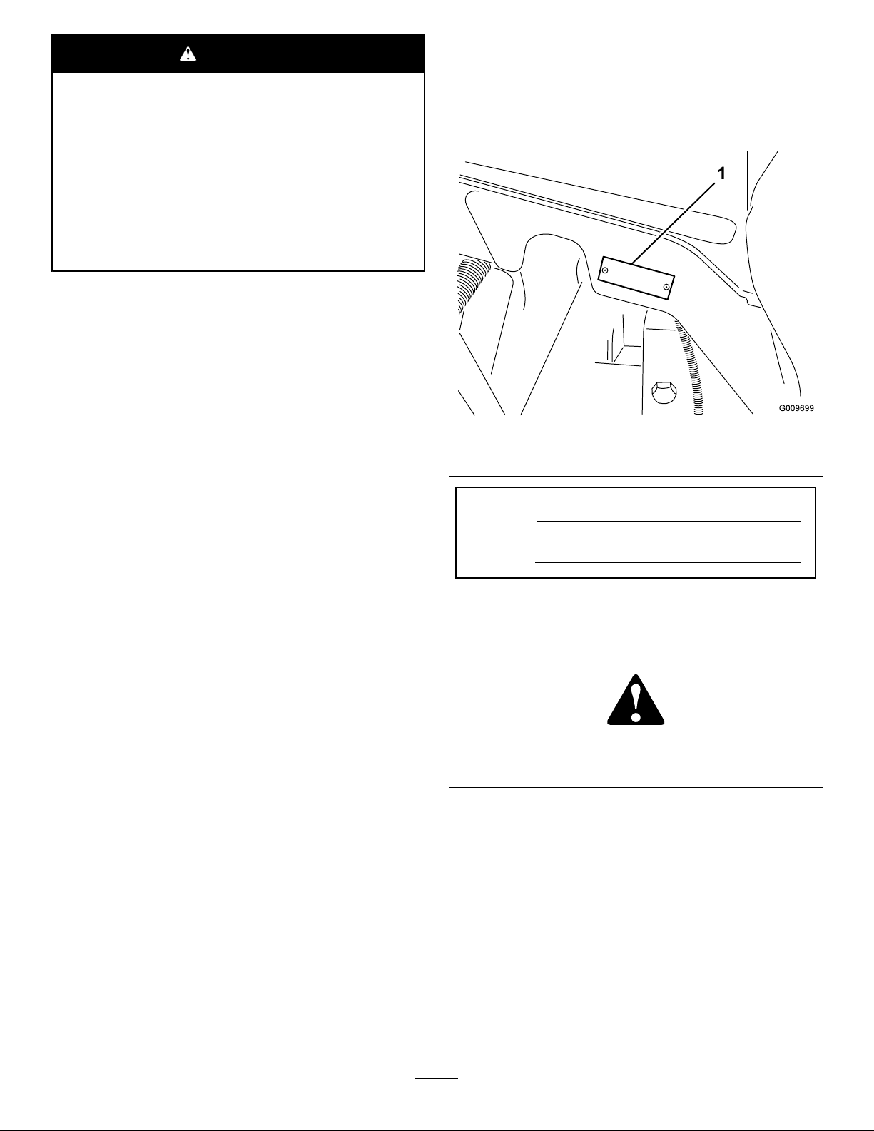
Wheneveryouneedservice,genuineT oroparts,oradditional
information,contactanAuthorizedServiceDealerorToro
CustomerServiceandhavethemodelandserialnumbersof
yourproductready.Figure1identiesthelocationofthe
modelandserialnumbersontherightfrontframemember
oftheproduct.Writethenumbersinthespaceprovided.
Important:Thisengineisequippedwithaspark
arrestermufer.ItisaviolationofCaliforniaPublic
ResourceCodeSection4442touseoroperatetheengine
onanyforest-covered,brush-covered,orgrass-covered
landwithoutasparkarrestermufermaintainedin
workingorder,ortheengineconstricted,equipped,and
maintainedforthepreventionofre.Otherstatesor
federalareasmayhavesimilarlaws.
ThissparkignitionsystemcomplieswithCanadianICES-002.
Theenclosed
Engine Owner's Man ual
issuppliedfor
informationregardingtheUSEnvironmentalProtection
Agency(EPA)andtheCaliforniaEmissionControl
Regulationofemissionsystems,maintenance,and
warranty.Replacementsmaybeorderedthroughthe
enginemanufacturer.
Introduction
Thismachineisaride-on,rotary-bladelawnmowerintended
tobeusedbyprofessional,hiredoperatorsincommercial
applications.Itisprimarilydesignedforcuttinggrasson
well-maintainedlawnsinparks,golfcourses,sportselds,
andoncommercialgrounds.Itisnotdesignedforcutting
brush,mowinggrassandothergrowthalongsidehighways,
orforagriculturaluses.
Figure1
1.Modelandserialnumberlocation
ModelNo.
SerialNo.
Thismanualidentiespotentialhazardsandhassafety
messagesidentiedbythesafetyalertsymbol(Figure2),
whichsignalsahazardthatmaycauseseriousinjuryordeath
ifyoudonotfollowtherecommendedprecautions.
Figure2
1.Safetyalertsymbol.
Thismanualuses2wordstohighlightinformation.
Importantcallsattentiontospecialmechanicalinformation
andNoteemphasizesgeneralinformationworthyofspecial
attention.
Readthisinformationcarefullytolearnhowtooperateand
maintainyourproductproperlyandtoavoidinjuryand
productdamage.Youareresponsibleforoperatingthe
productproperlyandsafely.
YoumaycontactT orodirectlyatwww .Toro.comforproduct
andaccessoryinformation,helpndingadealer,ortoregister
yourproduct.
©2014—TheToro®Company
8111LyndaleAvenueSouth
Bloomington,MN55420
Contactusatwww.Toro.com.
2
PrintedintheUSA
AllRightsReserved
Page 3

Contents
Safety...........................................................................4
SafeOperatingPractices...........................................4
ToroRidingMowerSafety........................................6
SafetyandInstructionalDecals.................................8
Setup...........................................................................12
AdjustingtheHeight-of-Cut....................................12
AdjustingtheRollerScraper(Optional).....................12
InstallingtheMulchingBafe(Optional)...................13
GreasingtheMachine.............................................13
CheckingFluidLevels.............................................13
ProductOverview.........................................................14
Controls...............................................................14
Specications........................................................17
TractionUnitSpecications.....................................17
CuttingUnitSpecications......................................17
Attachments/Accessories........................................17
Operation....................................................................18
CheckingtheEngine-oilLevel..................................18
CheckingtheCoolingSystem...................................19
FillingtheFuelTank...............................................19
CheckingtheHydraulic-uidLevel...........................20
CheckingtheTirePressure......................................21
StartingandStoppingtheEngine..............................21
CheckingtheInterlockSwitches...............................22
PushingorTowingtheMachine................................22
LocatingtheJackingPoints......................................23
LocatingtheTieDowns..........................................23
OperatingtheEngineCoolingFan............................23
SelectingaBlade.....................................................23
ChoosingAccessories.............................................24
OperatingTips......................................................24
Maintenance.................................................................26
RecommendedMaintenanceSchedule(s)......................26
DailyMaintenanceChecklist....................................27
ServiceIntervalChart.............................................28
PremaintenanceProcedures........................................29
RemovingtheHood...............................................29
Lubrication...............................................................29
GreasingtheBearingsandBushings..........................29
EngineMaintenance..................................................31
ServicingtheAirCleaner.........................................31
ServicingtheEngineOilandFilter............................32
AdjustingtheThrottle.............................................32
FuelSystemMaintenance...........................................33
ServicingtheFuelTank...........................................33
CheckingtheFuelLinesandConnections..................33
ServicingtheWaterSeparator..................................33
ServicingtheFuelPickupTubeScreen.......................33
BleedingAirfromtheInjectors................................34
ElectricalSystemMaintenance....................................34
ChargingandConnectingtheBattery........................34
ServicingtheBattery...............................................36
ServicingtheFuses.................................................36
DriveSystemMaintenance.........................................37
CheckingtheTorqueoftheWheelNuts.....................37
CheckingthePlanetaryGearDriveOil......................37
ChangingthePlanetaryGearDriveOil......................37
CheckingtheRearAxleLubricant.............................38
ChangingtheRearAxleLubricant.............................38
AdjustingtheTractionDriveforNeutral....................38
CheckingtheRearWheelToe-in...............................39
CoolingSystemMaintenance......................................40
ServicingtheEngineCoolingSystem........................40
BrakeMaintenance....................................................41
AdjustingtheServiceBrakes....................................41
BeltMaintenance......................................................41
ServicingtheAlternatorBelt....................................41
HydraulicSystemMaintenance....................................42
ChangingtheHydraulicFluid...................................42
ReplacingtheHydraulicFilters.................................42
CheckingtheHydraulicLinesandHoses....................43
ChangingtheCounterbalanceSettings.......................43
CuttingDeckMaintenance..........................................44
SeparatingtheCuttingDecksfromtheTraction
Unit..................................................................44
MountingtheCuttingDeckstotheTraction
Unit..................................................................45
ServicingtheBladePlane.........................................45
ServicingtheCutterBlade.......................................46
ServicingtheFrontRoller........................................47
Cleaning...................................................................48
ServicingtheSparkArresterMufer.........................48
Storage........................................................................48
PreparingtheTractionUnit.....................................48
PreparingtheEngine..............................................48
CuttingDeck.........................................................48
3
Page 4

Safety
Improperuseormaintenancebytheoperatororownercan
resultininjury.Toreducethepotentialforinjury,comply
withthesesafetyinstructionsandalwayspayattentionto
thesafetyalertsymbol,whichmeansCaution,Warning,or
Danger—personalsafetyinstruction.Failuretocomplywith
theinstructionmayresultinpersonalinjuryordeath.
SafeOperatingPractices
ThefollowinginstructionsareadaptedfromtheENISO
5395:2013andANSIB71.4-2012.
Training
•Readtheoperator'smanualandothertrainingmaterial
carefully.Befamiliarwiththecontrols,safetysigns,and
theproperuseoftheequipment.
•Iftheoperatorormechaniccannotreadthelanguageof
thismanual,itistheowner'sresponsibilitytoexplainthis
materialtothem.
•Neverallowchildrenorpeopleunfamiliarwiththese
instructionstouseorservicethemower.Local
regulationsmayrestricttheageoftheoperator.
•Nevermowwhilepeople,especiallychildren,orpetsare
nearby.
•Donotcarrypassengers.
•Alldriversandmechanicsshouldseekandobtain
professionalandpracticalinstruction.Theowneris
responsiblefortrainingtheusers.Suchinstructionshould
emphasize:
–theneedforcareandconcentrationwhenworking
withride-onmachines;
–controlofaride-onmachineslidingonaslopewill
notberegainedbytheapplicationofthebrake.The
mainreasonsforlossofcontrolare:
◊insufcientwheelgrip;
◊beingdriventoofast;
◊inadequatebraking;
◊thetypeofmachineisunsuitableforthetask;
◊lackofawarenessoftheeffectofground
conditions,especiallyslopes;
•Theowner/usercanpreventandisresponsiblefor
accidentsorinjuriesoccurringtopeopleordamageto
property.
Preparation
•Whilemowing,alwayswearsubstantialfootwear,long
trousers,ahardhat,safetyglasses,andhearingprotection.
Longhair,looseclothing,orjewelrymaygettangled
inmovingparts.Donotoperatetheequipmentwhen
barefootorwearingopensandals.
•Thoroughlyinspecttheareawheretheequipmentisto
beusedandremoveallobjectswhichmaybethrownby
themachine.
•Replacewornordamagedsilencers.
•Evaluatetheterraintodeterminewhataccessoriesand
attachmentsareneededtoproperlyandsafelyperform
thejob.Onlyuseaccessoriesandattachmentsapproved
bythemanufacturer.
•Checkthatoperator'spresencecontrols,safetyswitches,
andshieldsareattachedandfunctioningproperly.Donot
operateunlesstheyarefunctioningproperly.
Operation
•Donotoperatetheengineinaconnedspacewhere
dangerouscarbonmonoxidefumescancollect.
•Mowonlyindaylightoringoodarticiallight.
•Beforeattemptingtostarttheengine,disengageallblade
attachmentclutches,shiftintoneutral,andengagethe
parkingbrake.
•Donotputhandsorfeetnearorunderrotatingparts.
Keepclearofthedischargeopeningatalltimes.
•Rememberthereisnosuchthingasasafeslope.Travel
ongrassslopesrequiresparticularcare.Toguardagainst
overturning:
–donotstoporstartsuddenlywhengoingupor
downhill;
–machinespeedsshouldbekeptlowonslopesand
duringtightturns;
–stayalertforhumpsandhollowsandotherhidden
hazards;
–nevermowacrossthefaceoftheslope,unlessthe
mowerisdesignedforthispurpose.
–Usecounterweight(s)orwheelweightswhen
suggestedintheoperator'smanual.
•Stayalertforholesintheterrainandotherhiddenhazards.
•Watchoutfortrafcwhencrossingornearroadways.
•Stopthebladesfromrotatingbeforecrossingsurfaces
otherthangrass.
•Neveroperatethemachinewithdamagedguards,shields,
orwithoutsafetyprotectivedevicesinplace.Besure
thatallinterlocksareattached,adjustedproperly,and
functioningproperly.
•Donotchangetheenginegovernorsettingsoroverspeed
theengine.Operatingtheengineatexcessivespeedmay
increasethehazardofpersonalinjury.
•Beforeleavingtheoperator'sposition:
–stoponlevelground;
–disengagethepowertake-offandlowerthe
attachments;
–settheparkingbrake;
4
Page 5

–stoptheengineandremovethekey.
Important:Allowtheenginetoidlefor5minutes
beforeshuttingitoffafterafull-loadoperation.
Failuretodosomayleadtoturbochargertrouble.
•Stoptheengineinthefollowingconditions:
–beforefuelling;
–beforemakingheightadjustment.
–beforeclearingblockages;
–beforechecking,cleaning,orworkingonthemower;
–afterstrikingaforeignobjectorifanabnormal
vibrationoccurs.Inspectthemowerfordamage
andmakerepairsbeforestartingandoperatingthe
equipmentagain.
•Reducethethrottlesettingduringenginerun-out.
•Keephandsandfeetawayfromthecuttingunits.
•Lookbehindanddownbeforebackinguptobesureof
aclearpath.
•Slowdownandusecautionwhenmakingturnsand
crossingroadsandsidewalks.Stopbladesfromrotating.
•Beawareofthemowerdischargedirectionanddonot
pointitatanyone.
•Donotoperatethemowerundertheinuenceofalcohol
ordrugs
•Lightningcancausesevereinjuryordeath.Iflightning
isseenorthunderisheardinthearea,donotoperate
themachine;seekshelter.
•Usecarewhenloadingorunloadingthemachineinto
atrailerortruck
•Usecarewhenapproachingblindcorners,shrubs,trees,
orotherobjectsthatmayobscurevision.
•DonotremovetheROPS.
•AnyalterationstoaROPSmustbeapprovedbythe
manufacturer.
SafeHandlingofFuels
•Toavoidpersonalinjuryorpropertydamage,use
extremecareinhandlinggasoline.Gasolineisextremely
ammableandthevaporsareexplosive.
•Extinguishallcigarettes,cigars,pipes,andothersources
ofignition.
•Useonlyanapprovedfuelcontainer.
•Neverremovefuelcaporaddfuelwiththeengine
running.
•Allowenginetocoolbeforerefueling.
•Neverrefuelthemachineindoors.
•Neverstorethemachineorfuelcontainerwherethereis
anopename,spark,orpilotlightsuchasonawater
heateroronotherappliances.
•Neverllcontainersinsideavehicleoronatruckor
trailerbedwithaplasticliner.Alwaysplacecontainerson
thegroundawayfromyourvehiclebeforelling.
•Removeequipmentfromthetruckortrailerandrefuelit
ontheground.Ifthisisnotpossible,thenrefuelsuch
equipmentwithaportablecontainer,ratherthanfroma
fueldispensernozzle.
•Keepthenozzleincontactwiththerimofthefueltank
orcontaineropeningatalltimesuntilfuelingiscomplete.
•Donotuseanozzlelockopendevice.
•Iffuelisspilledonclothing,changeclothingimmediately.
•Neveroverllfueltank.Replacefuelcapandtighten
securely.
RolloverProtectionSystem
(ROPS)—UseandMaintenance
•TheROPSisanintegralandeffectivesafetydevice.Keep
afoldingROPSintheraisedandlockedpositionanduse
theseatbeltwhenoperatingthemachine.
•LowerafoldingROPStemporarilyonlywhenabsolutely
necessary.Donotweartheseatbeltwhenfoldeddown.
•Beawarethereisnorolloverprotectionwhenafolded
ROPSisinthedownposition.
•Becertainthattheseatbeltcanbereleasedquicklyin
theeventofanemergency.
•Checktheareatobemowedandneverfolddowna
foldingROPSinareaswherethereareslopes,drop-offs,
orwater.
•Checkcarefullyforoverheadclearances(i.e.branches,
doorways,electricalwires)beforedrivingunderany
objectsanddonotcontactthem.
•KeeptheROPSinsafeoperatingconditionby
periodicallythoroughlyinspectingfordamageand
keepingallmountingfastenerstight.
•ReplaceadamagedROPS.Donotrepairorrevise.
MaintenanceandStorage
•Keepallnuts,bolts,andscrewstighttobesurethatthe
equipmentisinsafeworkingcondition.
•Neverstoretheequipmentwithfuelinthetankinsidea
buildingwherefumesmayreachanopenameorspark.
•Allowtheenginetocoolbeforestoringinanyenclosure.
•Toreducetherehazard,keeptheengine,
silencer/mufer,batterycompartment,andfuel-storage
areafreeofgrass,leaves,orexcessivegrease.
•Keepallpartsingoodworkingconditionandallhardware
andhydraulicttingstightened.Replaceallwornor
damagedpartsanddecals.
•Ifthefueltankhastobedrained,dothisoutdoors.
•Becarefulduringadjustmentofthemachinetoprevent
entrapmentofthengersbetweenmovingbladesand
xedpartsofthemachine.
•Onmulti-spindlemowers,takecareasrotatingoneblade
cancauseotherbladestorotate.
•Disengagedrives,lowerthecuttingunits,settheparking
brake,stoptheengine,andremovetheignitionkey.Wait
5
Page 6

forallmovementtostopbeforeadjusting,cleaning,or
repairing.
•Cleangrassanddebrisfromcuttingunits,drives,
silencers/mufers,andenginetohelppreventres.Clean
upoilorfuelspillage.
•Usejackstandstosupportcomponentswhenrequired.
•Carefullyreleasepressurefromcomponentswithstored
energy.
•Disconnectthebatterybeforemakinganyrepairs.
Disconnectthenegativeterminalrstandthepositive
last.Connectthepositiverstandnegativelast.
•Usecarewhencheckingtheblades.Wearglovesanduse
cautionwhenservicingthem.
•Keephandsandfeetawayfrommovingparts.Ifpossible,
donotmakeadjustmentswiththeenginerunning.
•Chargebatteriesinanopen,well-ventilatedarea,away
fromsparkandames.Unplugthechargerbefore
connectingordisconnectingitfromthebattery.Wear
protectiveclothinganduseinsulatedtools.
•Storethemachinewiththecuttingunitsinthelowered
positionorsecurethewingdeckswiththestoragelatches
topreventthemfromunintentionallylowering.
Hauling
•Usecarewhenloadingorunloadingthemachineintoa
trailerortruck.
•Usefullwidthrampsforloadingmachineintotraileror
truck.
•Tiethemachinedownsecurelyusingstraps,chains,cable,
orropes.Bothfrontandrearstrapsshouldbedirected
downandoutwardfromthemachine.
ToroRidingMowerSafety
ThefollowinglistcontainssafetyinformationspecictoToro
productsorothersafetyinformationthatyoumustknowthat
isnotincludedintheCEN,ISO,orANSIstandard.
Thisproductiscapableofamputatinghandsandfeetand
throwingobjects.Alwaysfollowallsafetyinstructionsto
avoidseriousinjuryordeath.
Useofthisproductforpurposesotherthanitsintendeduse
couldprovedangeroustouserandbystanders.
WARNING
Engineexhaustcontainscarbonmonoxide,which
isanodorless,deadlypoisonthatcankillyou.
Donotrunengineindoorsorinanenclosedarea.
•Knowhowtostoptheenginequickly .
•Donotoperatethemachinewhilewearingtennisshoes
orsneakers.
•Wearingsafetyshoesandlongpantsisadvisableand
requiredbysomelocalordinancesandinsurance
regulations.
•Handlefuelcarefully.Wipeupanyspills.
•Checkthesafetyinterlockswitchesdailyforproper
operation.Ifaswitchshouldfail,replacetheswitch
beforeoperatingthemachine.
•Beforestartingtheengine,sitontheseat.
•Usingthemachinedemandsattention.Topreventloss
ofcontrol:
–Donotdriveclosetosandtraps,ditches,creeks,
embankments,orotherhazards.
–Reducespeedwhenmakingsharpturns.Avoid
suddenstopsandstarts.
–Whennearorcrossingroads,alwaysyieldthe
right-of-way.
–Applytheservicebrakeswhengoingdownhillto
keepforwardspeedslowandtomaintaincontrolof
themachine.
•WhenoperatingamachinewithROPS(roll-over
protectionsystem)neverremovetheROPSandalways
usetheseatbelt.
•Raisethecuttingunitswhendrivingfromoneworkarea
toanother.
•Donottouchtheengine,silencer/mufer,orexhaust
pipewhiletheengineisrunningorsoonafterithas
stopped,becausetheseareascouldbehotenoughto
causeburns.
•Onanyhill,thereisthepossibilityoftippingorrolling
over,buttheriskincreasesastheslopeangleincreases.
Steephillsshouldbeavoided.
•Thecuttingunitsmustbeloweredwhengoingdown
slopes,tomaintainsteeringcontrol.
•Engagethetractiondriveslowly,alwayskeepyourfoot
onthetractionpedal,especiallywhentravelingdownhill.
•Usereverseonthetractionpedalforbraking.
•Ifthemachinestallswhenclimbingaslope,donotturn
themachinearound.Alwaysbackslowly,straightdown
theslope.
•Whenapersonorpetappearsunexpectedlyinornearthe
mowingarea,stopmowing.Carelessoperation,combined
withterrainangles,ricochets,orimproperlypositioned
guardscanleadtothrownobjectinjuries.Donotresume
mowinguntiltheareaiscleared.
MaintenanceandStorage
•Makesurethatallhydrauliclineconnectorsaretightand
allhydraulichosesandlinesareingoodconditionbefore
applyingpressuretothesystem.
•Keepyourbodyandhandsawayfrompinholeleaksor
nozzlesthatejecthydraulicuidunderhighpressure.
6
Page 7

Usepaperorcardboard,notyourhands,tosearchfor
leaks.Hydraulicuidescapingunderpressurecanhave
sufcientforcetopenetratetheskinandcauseserious
injury.Seekimmediatemedicalattentionifuidis
injectedintoskin.
•Beforedisconnectingorperforminganyworkonthe
hydraulicsystem,allpressureinthesystemmustbe
relievedbystoppingtheengineandloweringthecutting
unitsandattachmentstotheground.
•Checkallfuellinesfortightnessandwearonaregular
basis.Tightenorrepairthemasneeded.
•Iftheenginemustberunningtoperformamaintenance
adjustment,keephands,feet,clothing,andanypartsof
thebodyawayfromthecuttingunits,attachments,and
anymovingparts.
•Toensuresafetyandaccuracy,haveanAuthorizedToro
Distributorcheckthemaximumenginespeedwitha
tachometer.
•Ifmajorrepairsareeverneededorifassistanceisdesired,
contactanAuthorizedToroDistributor.
•UseonlyToro-approvedattachmentsandreplacement
parts.Thewarrantymaybevoidedifusedwith
unapprovedattachments.
7
Page 8
SafetyandInstructionalDecals
Safetydecalsandinstructionsareeasilyvisibletotheoperatorandarelocatednearanyareaofpotential
danger.Replaceanydecalthatisdamagedorlost.
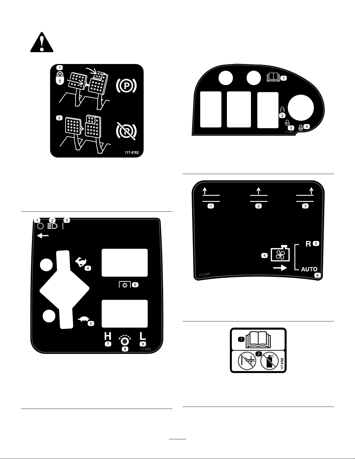
117–2385
1.Toengagetheparking
brake,securethebrake
pedalswiththelockingpin,
presstheparkingbrake
pedalsandengagethetoe
pedal.
117-4763
2.Todisengagetheparking
brake,disengagethe
lockingpinandreleasethe
pedals.
1.ReadtheOperator’s
Manual.
2.Engine—start4.Engine—stop
3.Engine—preheat
117–2387
1.Raiseleftdeck4.Coolingfan
2.Raisecenterdeck5.Reverse
3.Raiserightdeck6.Automatic
117–2384
1.Off6.PowerT ake-off(PTO)
2.Headlights7.High
3.On
4.Fast9.Low
5.Slow
8.Tractioncontrol
117-4765
1.ReadtheOperator'sManual.
2.Donotusestartingaids.
8
Page 9
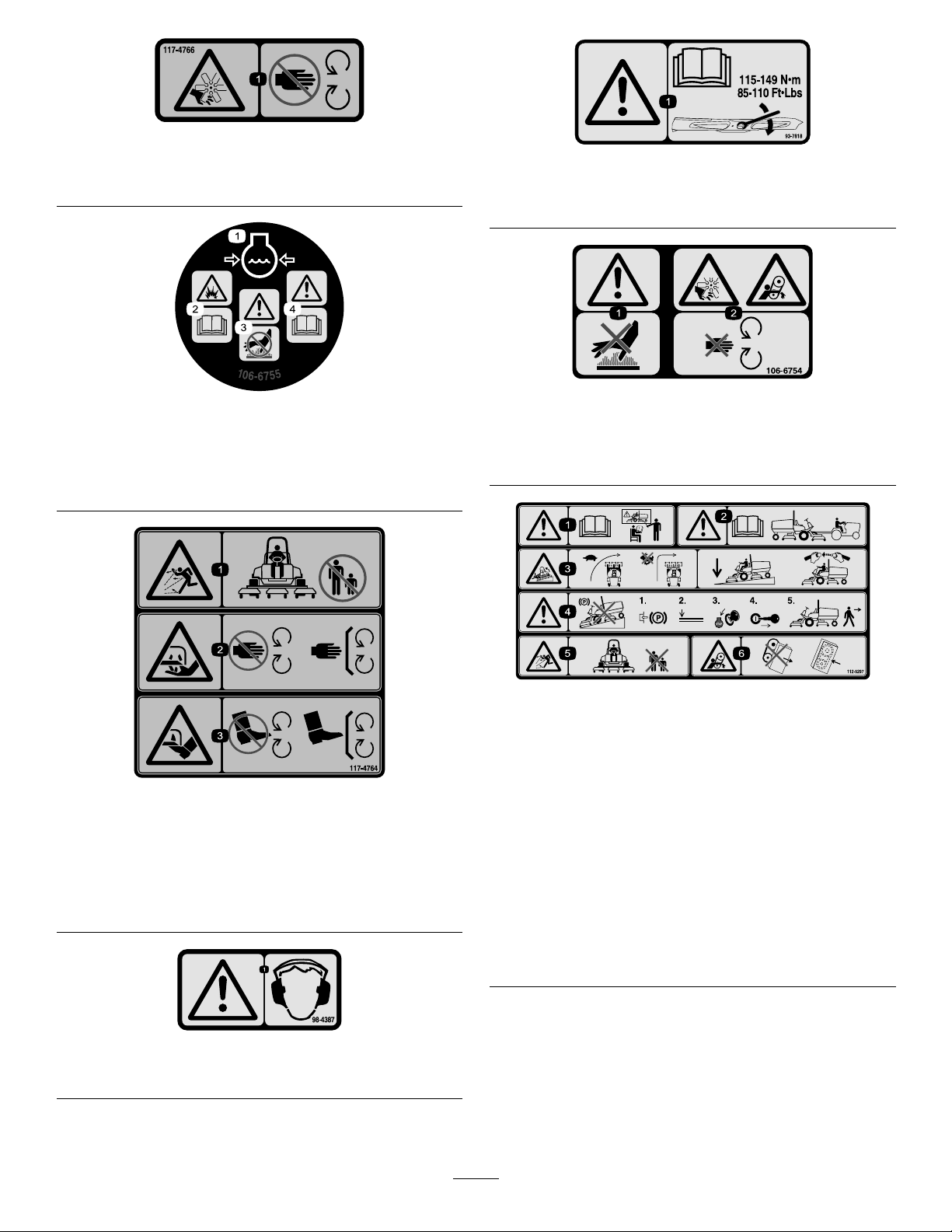
117-4766
1.Cutting/dismembermenthazard;fan—stayawayfrom
movingparts.
93-7818
1.Warning—readtheOperator'sManualforinstructionson
torquingthebladebolt/nutto115-149N-m(85-110ft-lb).
106-6755
1.Enginecoolantunder
pressure.
2.Explosionhazard—read
theOperator'sManual.
3.Warning—donottouchthe
hotsurface.
4.Warning—readthe
Operator'sManual.
117-4764
1.Thrownobjecthazard—keepbystandersasafedistance
fromthemachine.
2.Cuttinghazardofhand,mowerblade—stayawayfrom
movingparts,keepallguardsandshieldsinplace.
3.Cuttinghazardoffoot,mowerblade—stayawayfrom
movingparts,keepallguardsandshieldsinplace.
106-6754
1.Warning—donottouchthehotsurface.
2.Cutting/dismembermenthazard,fanandentanglement
hazard,belt—stayawayfrommovingparts.
112-5297
1.Warning—readtheOperator'sManual,donotoperatethis
machineunlessyouaretrained.
2.Warning—readtheOperator'sManualbeforetowingthe
machine.
3.Tippinghazard—slowmachinebeforeturning,donotturn
athighspeeds;lowerthecuttingunitwhendrivingdown
slopes;usearolloverprotectionsystemandweartheseat
belt
4.Warning—donotparkthemachineonslopes;engagethe
parkingbrake,lowerthecuttingunits,stoptheengineand
removetheignitionkeybeforeleavingthemachine.
5.Thrownobjecthazard—keepbystandersasafedistance
fromthemachine.
6.Entanglementhazard,belt—stayawayfrommovingparts,
keepallguardsandshieldsinplace.
1.Warning—wearhearingprotection.
98-4387
9
Page 10
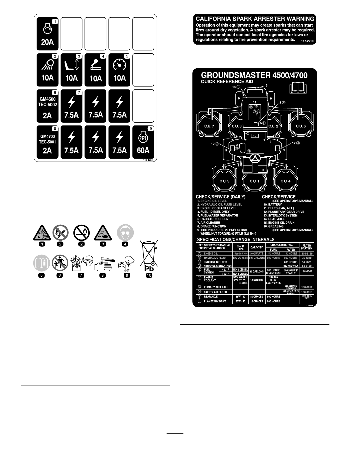
117-4761
1.Starter,20A6.GM4500controller,2A
2.Worklight,10A7.Powersupplied,7.5A
3.Seat,10A8.GM4700controller,2A
4.Powerpoint,10A9.Enginepreheat,60A
5.Gauges,10A
117–2718
BatterySymbols
Someorallofthesesymbolsareonyourbattery
1.Explosionhazard
2.Nore,opename,or
smoking.
3.Causticliquid/chemical
burnhazard
4.Weareyeprotection9.Flusheyesimmediately
5.ReadtheOperator's
Manual.
6.Keepbystandersasafe
7.Weareyeprotection;
8.Batteryacidcancause
10.Containslead;donot
distancefromthebattery.
117-4758
explosivegasescan
causeblindnessandother
injuries
blindnessorsevereburns.
withwaterandgetmedical
helpfast.
discard.
10
Page 11
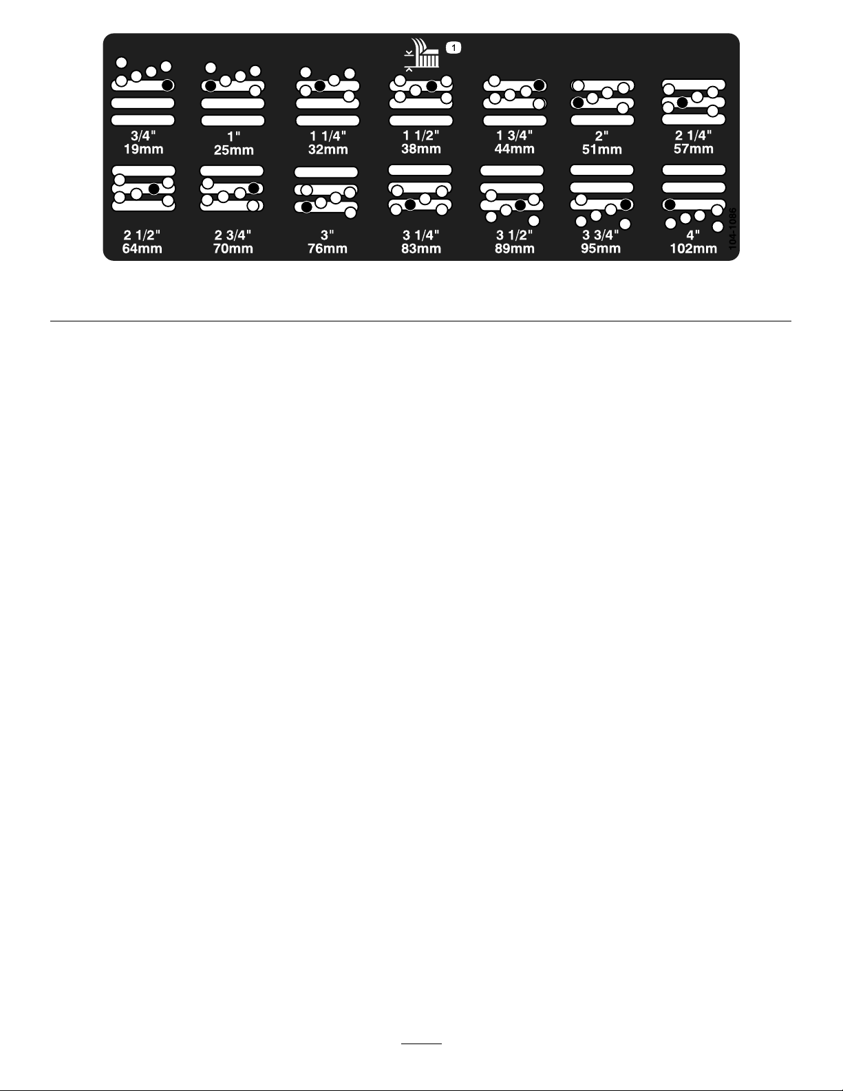
1.Heightofcut
104-1086
11
Page 12
Setup
MediaandAdditionalParts
Description
Operator'sManual
EngineOperator'sManual
PartsCatalog
OperatorTrainingMaterial
Note:Determinetheleftandrightsidesofthemachinefromthenormaloperatingposition.
AdjustingtheHeight-of-Cut
Important:Thiscuttingdeckoftencutsapproximately
6mm(1/4inch)lowerthanareelcuttingunitwiththe
samebenchsetting.Itmaybenecessarytohavethese
rotarycuttingdeck’sbenchset6mm(1/4inch)above
thatofreelscuttinginthesamearea.
Important:Accesstotherearcuttingunitsisgreatly
improvedbyremovingthecuttingunitfromthetractor.
IftheunitisequippedwithaSidewinder®,sidewindthe
cuttingunitstotheright,removetherearcuttingunit,
andslideitouttotherightside.
Qty.
1
1
1
1
Readbeforeoperatingmachine
Readbeforeoperatingengine
Usetoreferencepartnumbers
Viewbeforeoperatingmachine
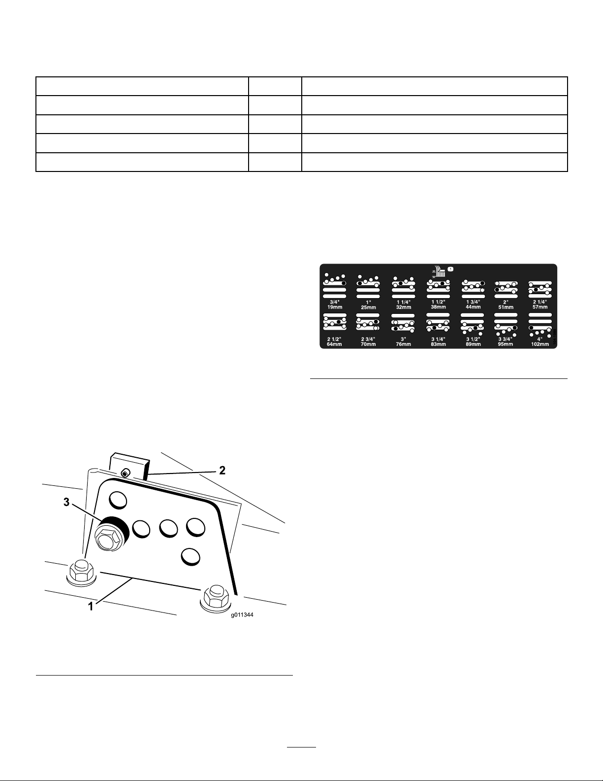
5.Movethechambertothedesiredheight-of-cutand
installaspacerintothedesignatedheight-of-cuthole
andslot(Figure4).
Use
Figure4
1.Lowerthecuttingdecktotheground,stoptheengine,
andremovethekeyfromignitionswitch.
2.Loosentheboltsecuringeachheight-of-cutbracketto
theheight-of-cutplate(frontandeachside)(Figure3).
3.Beginningwithfrontadjustment,removethebolt.
Figure3
1.Heightofcutbracket3.Spacer
2.Heightofcutplate
6.Positionthetappedplateinlinewiththespacer.
7.Installtheboltngertight.
8.Repeatsteps4-7foreachsideadjustment.
9.Tightenallthreeboltsto41N-m(30ft-lb).Always
tightenthefrontboltrst.
Note:Adjustmentsofmorethan3.8cm(1-1/2
inches)mayrequiretemporaryassemblytoan
intermediateheighttopreventbinding(e.g.changing
from3.1to7cm(1.25to2.75inch)height-of-cut).
AdjustingtheRollerScraper
(Optional)
Theoptionalrearrollerscraperisdesignedtoworkbest
whenthereisanevengapof0.5to1mm(0.020–0.040inch)
betweenthescraperandroller.
1.Loosenthegreasettingandthemountingscrew
(Figure5).
4.Whilesupportingthechamber,removethespacer
(Figure3).
12
Page 13
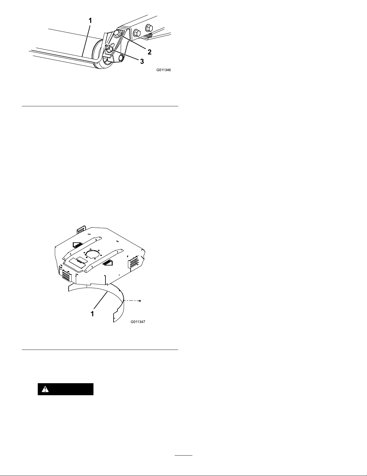
G011346
1
2
3
1.Rollerscraper
G011347
1
2.Mountingscrew
Figure5
3.Greasetting
GreasingtheMachine
Beforethemachineisoperated,itmustbegreasedtoensure
properlubrication.Failuretoproperlygreasethemachine
willresultinprematurefailureofcriticalparts.
CheckingFluidLevels
1.Checktherear-axlelubricantlevelbeforetheengineis
rststarted,refertoCheckingtheRearAxleLubricant.
2.Checkthehydraulic-uidlevelbeforetheengineisrst
started,refertoCheckingtheHydraulicFluidLevel.
2.Slidethescraperupordownuntilagapof0.5to1
mm(0.020to0.040inch)isachievedbetweentherod
andtheroller.
3.Securethegreasettingandscrewto41N-m(30ft-lb)
inanalternatingsequence.
InstallingtheMulchingBafe
(Optional)
1.Thoroughlycleandebrisfromthemountingholeson
therearwallandleftsidewallofthechamber.
2.Installthemulchingbafeintherearopeningand
secureitwith5angeheadbolts(Figure6).
3.Checktheengine-oillevelbeforeandaftertheengine
isrststarted,refertoCheckingtheEngineOilLevel.
Figure6
1.Mulchingbafe
3.Verifythatmulchingbafedoesnotinterferewith
thetipofthebladeanddoesnotprotrudeinsidethe
surfaceoftherearchamberwall.
WARNING
Donotusethehighliftbladewiththe
mulchingbafe.Thebladecouldbreak,
resultinginpersonalinjuryordeath.
13
Page 14
ProductOverview
Controls
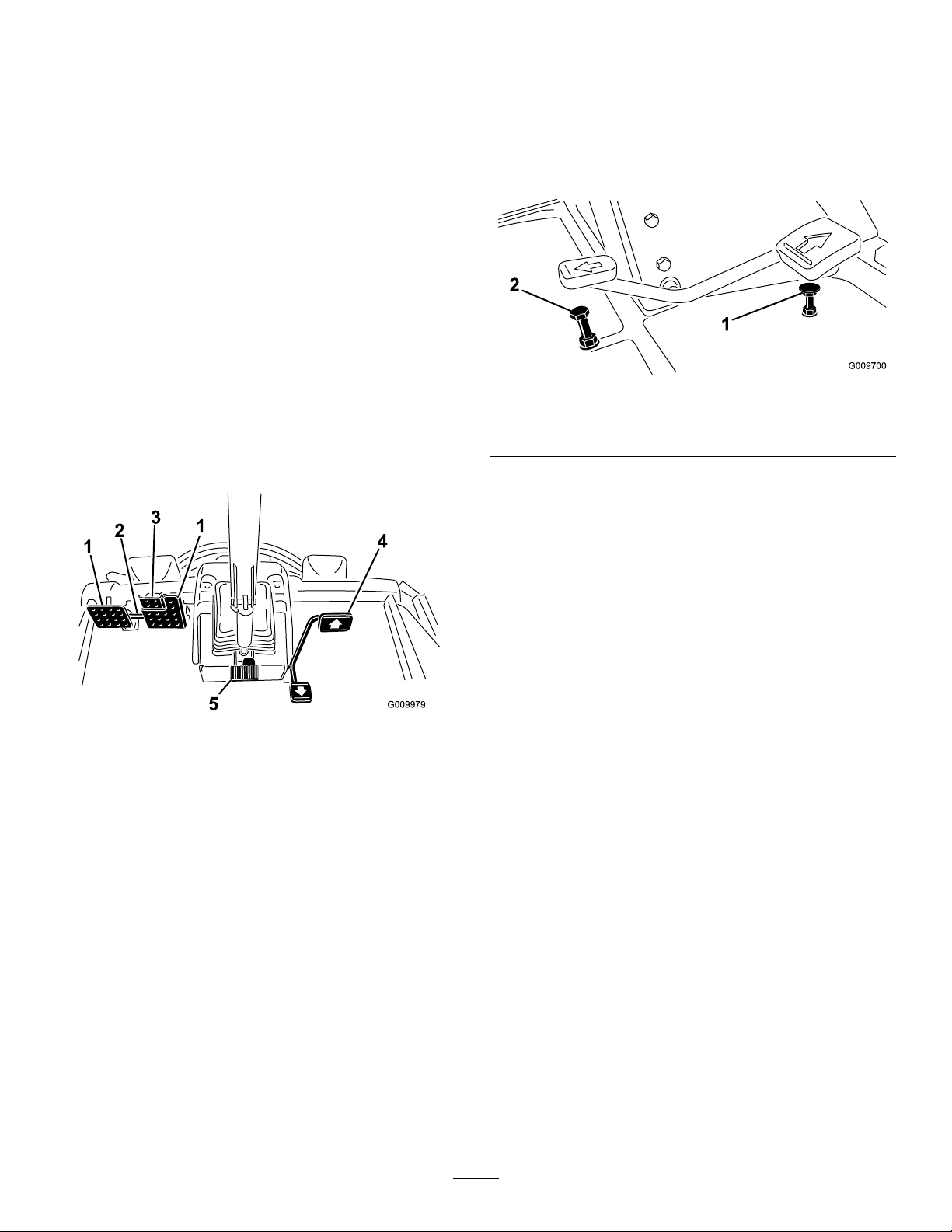
Speed-limiterScrews
Adjustthescrew(s)(Figure8)tolimittheextenttowhich
youcanpressthetractionpedalintheforwardorreverse
directiontolimitspeed.
BrakePedals
2footpedals(Figure7)operateindividualwheelbrakesfor
turningassistanceandtoaidinobtainingbetterside-hill
traction.
Pedal-lockingLatch
Thepedal-lockinglatch(Figure7)connectsthepedals
togethertoengagetheparkingbrake.
Parking-brakePedal
Toengagetheparkingbrake,(Figure7)connectthepedals
togetherwiththepedal-lockinglatch,pushdownonthe
rightbrakepedalwhileengagingthetoepedal.Torelease
theparkingbrake,press1ofthebrakepedalsuntilthe
parking-brakelatchretracts.
Important:Thespeed-limiterscrewmuststopthe
tractionpedalbeforethepumpreachesfullstroke,or
damagetothepumpmayoccur.
Figure8
1.Forwardspeed-limiter
screw
2.Reversespeed-limiter
screw
DiagnosticLight
Thediagnosticlight(Figure9)willilluminateshouldasystem
faultberecognized.
Coolant-temperatureGauge
Figure7
1.Brakepedal4.Tractionpedal
2.Pedal-lockinglatch5.Tilt-steeringpedal
3.Parking-brakepedal
TractionPedal
Thetractionpedal(Figure7)controlsforwardandreverse
operation.Pressthetopofthepedaltomoveforwardandthe
bottomtomovebackward.Groundspeeddependsonhow
faryoupressthepedal.Forno-load,maximumgroundspeed,
fullypressthepedalwhilethethrottleisintheFastposition.
Tostop,reduceyourfootpressureonthetractionpedaland
allowittoreturntothecenterposition.
Tilt-steeringPedal
Totiltthesteeringwheeltowardsyou,pressthefootpedal
(Figure7)down,andpullthesteeringtowertowardyouto
themostcomfortablepositionandthenreleasethepedal.
Duringnormaloperatingconditionsthegauge(Figure9)
shouldbeinthegreenrange.Checkthecoolingsystemifthe
gaugegoestotheyelloworredrange.
Oil-pressureWarningLight
Thelight(Figure9)illuminateswhentheengineoilpressure
isdangerouslylow.
ChargeIndicator
Thechargeindicator(Figure9)illuminateswhenthesystem
chargingcircuitmalfunctions.
KeySwitch
Thekeyswitch(Figure9)has3positions:Off,On/Preheat,
andStart.
PTOSwitch
ThePTOswitch(Figure9)has2positions:Out(start)and
In(stop).PullthePTObuttonouttoengagethecutting
unitblades.Pushinthebuttontodisengagethecuttingunit
blades.
High-lowSpeedControl
Theswitch(Figure9)allowsthespeedrangetoincreasefor
transportofthemachine.Cuttingdeckswillnotoperatein
14
Page 15
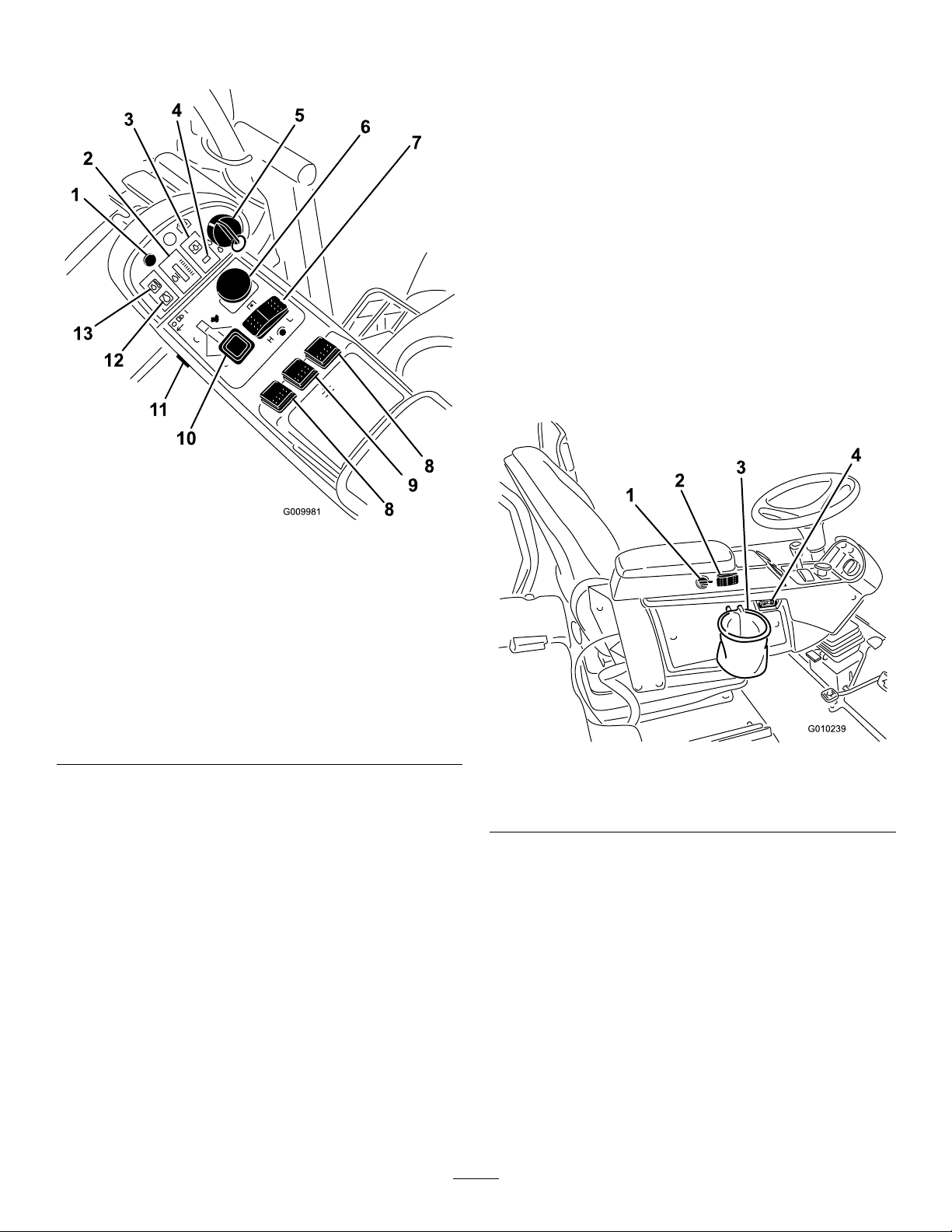
thehighrange.Also,thedeckscannotbeloweredfromthe
transportpositionwhentheswitchisinthehighrange.
LightSwitch
Presstheloweredgeoftheswitch(Figure9)toturnonthe
lights.Presstheupperedgeoftheswitchtoturnoffthelights.
Glow-plugIndicatorLight
Whenlit,theglow-plugindicatorlight(Figure9)indicates
thattheglowplugsareon.
Coolant-temperatureWarningLight
Thelight(Figure9)illuminatesandthecuttingunitsshut
down(PTOdisengages).Ifthetemperaturecontinuestorise
theenginewillshutdown.
PowerPoint
Thepowerpoint(Figure10)isusedtopoweroptional12-volt
electricalaccessories.
Figure9
1.Diagnosticlight
2.Coolant-temperature
gauge
3.Oil-pressurewarninglight
4.Chargeindicator
5.Keyswitch
6.PTOswitch13.Coolant-temperature
7.High-lowspeedcontrol
8.Liftswitches(GM4700
only)
9.Liftswitch(GM4500and
GM4700)
10.Throttlecontrol
11.Lightswitch
12.Glow-plugindicatorlight
warninglight
LiftSwitches
Theliftswitches(Figure9)raiseandlowerthecutting
units.Presstheswitchesforwardtolowerthecuttingunits
andbackwardtoraisethecuttingunits.Whenstartingthe
machine,withthecuttingunitsinthedownposition,pressthe
liftswitchdowntoallowthecuttingunitstooatandmow .
Note:Thedeckswillnotlowerwhileinthehigh-speed
range,andtheywillnotraiseorloweriftheoperatorisout
oftheseatwhentheengineisrunning.
ThrottleControl
Movethecontrol(Figure9)forwardtoincreasetheengine
speedandrearwardtodecreasethespeed.
Figure10
1.Powerpoint3.Bagholder
2.Engine-cooling-fanswitch
4.Hourmeter
Engine-cooling-fanSwitch
Themachineisequippedwithahydraulicallydriven
auto-reversingengine-coolingfan.Thefanswitch(Figure10)
has2positions:R(manualreverse)andAuto(normal).Refer
toOperatingtheEngineCoolingFan(page23).
BagHolder
Usethebagholder(Figure10)forstorage.
HourMeter
Thehourmeter(Figure10)showsthetotalhoursthatthe
machinehasbeenoperated.
15
Page 16
FuelGauge
1
2
3
4
5
G024916
Thefuelgauge(Figure11)indicatestheleveloffuelinthe
tank.
Figure11
1.Fuelgauge
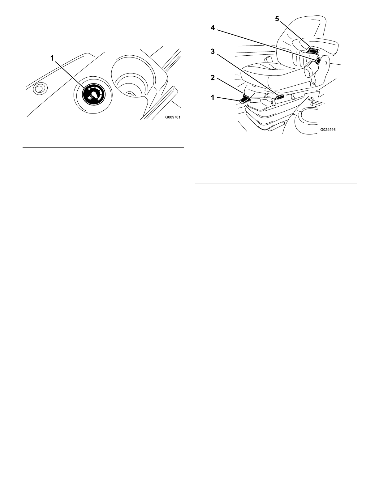
SeatAdjustments
ForeandAftAdjustingLever
Pulloutonthelevertoslidetheseatforeoraft(Figure12).
SeatArmrestAdjustingKnob
Rotatetheknobtoadjusttheseatarmrestangle(Figure12).
Seat-backAdjustingLever
Movethelevertoadjusttheseat-backangle(Figure12).
Weightgauge
Theweightgaugeindicateswhentheseatisadjustedtothe
weightoftheoperator(Figure12).Youcanmakeheight
adjustmentsbypositioningthesuspensionwithintherange
ofthegreenregion.
Figure12
1.Weight-adjustinglever
2.Weightgauge5.Armrestadjustingknob
3.Foreandaftadjusting
lever
Weight-adjustingLever
4.Seat-backadjustinglever
Adjustforoperatorweight(Figure12).Pulluponthelever
toincreasetheairpressureandpushdowntodecreasetheair
pressure.Theproperadjustmentisattainedwhentheweight
gaugeisinthegreenregion.
16
Page 17

Specications
Note:Specicationsanddesignaresubjecttochangewithoutnotice.
TractionUnitSpecications
4500-D4700-D
Widthofcut2.8m(109inches)3.8m(150inches)
Overallwidth,
cuttingunits
down
Overallwidth,
cuttingunitsup
(transport)
Overalllength370cm(145.8inches)370cm(145.8inches)
Heightwith
ROPS
Ground
clearance
Trackwidth,
front
Trackwidth,
rear
Wheelbase
Netweight(with
cuttingunits
andnouids)
286cm(1 12.8inches)391cm(153.8inches)
224cm(88.25inches)224cm(88.25inches)
216cm(85inches)216cm(85inches)
15cm(6inches)15cm(6inches)
224cm(88.25inches)224cm(88.25inches)
141cm(55.5inches)141cm(55.5inches)
171cm(67.5inches)171cm(67.5inches)
1995kg(4400lb)2245kg(4950lb)
CuttingUnitSpecications
Length
Width
Height
Weight
86.4cm(34inches)
86.4cm(34inches)
24.4cm(9.6inches)
tocarriermount
26.7cm(10–1/2inches)
at3/4inchheightofcut
34.9cm(13–3/4inches)at
4inchheightofcut
88kg(195pounds)
Attachments/Accessories
AselectionofToroapprovedattachmentsandaccessoriesisavailableforusewiththemachinetoenhanceandexpand
itscapabilities.ContactyourAuthorizedServiceDealerorDistributororgotowww .Toro.comforalistofallapproved
attachmentsandaccessories.
17
Page 18

Operation
Note:Determinetheleftandrightsidesofthemachine
fromthenormaloperatingposition.
CAUTION
Thismachineproducessoundlevelsinexcessof
85dBAattheoperator'searandcancausehearing
lossthroughextendedperiodsofexposure.
Wearhearingprotectionwhenoperatingthis
machine.
Theoillevelshouldbeinthesaferange(Figure13).
CAUTION
Ifyouleavethekeyintheignitionswitch,someone
couldaccidentlystarttheengineandseriously
injureyouorotherbystanders.
Removethekeyfromtheignitionbeforeyoudoany
maintenance.
CheckingtheEngine-oilLevel
ServiceInterval:Beforeeachuseordaily
Theengineisshippedwithoilinthecrankcase;however,the
oillevelmustbecheckedbeforeandaftertheengineisrst
started.
Thecrankcasecapacityisapproximately9.5L(10USqt)with
thelter.
Usehigh-qualityengineoilthatmeetsthefollowing
specications:
•APIClassicationLevelRequired:CH-4,CI-4,orhigher.
•Preferredoil:SAE15W-40(above-18°C[0°F])
•Alternateoil:SAE10W-30or5W-30(alltemperatures)
Note:ToroPremiumEngineoilisavailablefromyour
distributorineither15W-40or10W-30viscosity.Seethe
partscatalogforpartnumbers.
Note:Thebesttimetochecktheengineoiliswhenthe
engineiscoolbeforeithasbeenstartedfortheday.Ifit
hasalreadybeenrun,allowtheoiltodrainbackdownto
thesumpforatleast10minutesbeforechecking.Ifthe
oillevelisatorbelowtheAddmarkonthedipstick,add
oiltobringtheoilleveltotheFullmark.Donotoverll.
IftheoillevelisbetweentheFullandAddmarks,nooil
additionisrequired.
Figure13
1.Dipstick
4.Iftheoilisbelowthesaferange,removethellcap
(Figure14)andaddoiluntilthelevelreachestheFull
mark.Donotoverll.
Figure14
1.Oil-llcap
Note:Whenusingdifferentoil,drainalloldoilfrom
thecrankcasebeforeaddingnewoil.
5.Installtheoilllcapanddipstick.
6.Closetheenginecoverandsecureitwiththelatches.
1.Parkthemachineonalevelsurface.
2.Unlocktheenginecoverlatchesandopentheengine
cover.
3.Removethedipstick,wipeitclean,installthedipstick
intothetube,andpullitoutagain.
18
Page 19

CheckingtheCoolingSystem
FillingtheFuelTank
ServiceInterval:Beforeeachuseordaily
Checkthecoolantlevelatthebeginningofeachday .The
capacityofthesystemis12.3L(13USqt).
1.Carefullyremovetheradiatorcap.
CAUTION
Iftheenginehasbeenrunning,the
pressurized,hotcoolantcanescapeandcause
burns.
•Donotopentheradiatorcapwhenthe
engineisrunning.
•Usearagwhenopeningtheradiatorcap,
andopenthecapslowlytoallowsteamto
escape.
Useonlyclean,freshdieselfuelorbiodieselfuelswithlow
(<500ppm)orultra-low(<15ppm)sulfurcontent.The
minimumcetaneratingshouldbe40.Purchasefuelin
quantitiesthatcanbeusedwithin180daystoensurefuel
freshness.
Fueltankcapacity:83L(22USgallons)
Usesummer-gradedieselfuel(Number2-D)attemperatures
above-7°C(20°F)andwinter-gradedieselfuel(Number1-D
orNumber1-D/2-Dblend)below-7°C(20°F).Useof
winter-gradefuelatlowertemperaturesprovidesalowerash
pointandcold-owcharacteristicswhichwilleasestarting
andreducefuel-lterplugging.
Useofsummer-gradefuelabove-7°C(20°F)willcontribute
towardlongerfuel-pumplifeandincreasedpowercompared
towinter-gradefuel.
Important:Donotusekeroseneorgasolineinsteadof
dieselfuel.Failuretoobservethiscautionwilldamage
theengine.
WARNING
Fuelisharmfulorfatalifswallowed.Long-term
exposuretovaporscancauseseriousinjuryand
illness.
Figure15
1.Expansiontank
2.Checkthecoolantlevelintheradiator.
Note:Theradiatorshouldbelledtothetopofthe
llerneckandtheexpansiontanklledtotheFull
mark(Figure15).
3.Ifthecoolantislow ,adda50/50mixtureofwaterand
ethyleneglycolantifreeze.
Important:Donotusewateronlyor
alcohol/methanol-basedcoolants.
4.Installtheradiatorcapandtheexpansion-tankcap.
•Avoidprolongedbreathingofvapors.
•Keepfaceawayfromnozzleandgastankor
conditioneropening.
•Keepfuelawayfromeyesandskin.
BiodieselReady
Thismachinecanalsouseabiodieselblendedfuelofup
toB20(20%biodiesel,80%petrodiesel).Thepetrodiesel
portionshouldbeloworultra-lowsulfur.Observethe
followingprecautions:
•Thebiodieselportionofthefuelmustmeetspecication
ASTMD6751orEN14214.
•TheblendedfuelcompositionshouldmeetASTMD975
orEN590.
•Paintedsurfacesmaybedamagedbybiodieselblends.
•UseB5(biodieselcontentof5%)orlesserblendsincold
weather.
•Monitorseals,hoses,andgasketsincontactwithfuelas
theymaybedegradedovertime.
•Fuel-lterpluggingmaybeexpectedforatimeafter
convertingtobiodieselblends.
•Contactyourdistributorifyouwishformoreinformation
onbiodiesel.
19
Page 20

DANGER
DANGER
Incertainconditions,fuelisextremelyammable
andhighlyexplosive.Areorexplosionfromfuel
canburnyouandothersandcandamageproperty.
•Useafunnelandllthefueltankoutdoors,in
anopenarea,whentheengineiscold.Wipeup
anyfuelthatspills.
•Neverllthefueltankinsideanenclosedtrailer.
•Donotllthefueltankcompletelyfull.Addfuel
tothefueltankuntilthelevelis6to13mm(1/4
to1/2inch)belowthetopofthetank,notthe
llerneck.Thisemptyspaceinthetankallows
thefueltoexpand.
•Neversmokewhenhandlingfuel,andstayaway
fromanopenameorwherefuelfumesmaybe
ignitedbyaspark.
•Storefuelinanapprovedcontainerandkeepit
outofthereachofchildren.Neverbuymore
thana180-daysupplyoffuel.
•Donotoperatewithouttheentireexhaust
systeminplaceandinproperworkingcondition.
Incertainconditionsduringfueling,static
electricitycanbereleased,causingasparkwhich
canignitethefuelvapors.Areorexplosionfrom
fuelcanburnyouandothersandcandamage
property.
•Alwaysplacefuelcontainersonthegroundaway
fromyourvehiclebeforelling.
•Donotllfuelcontainersinsideavehicleoron
atruckortrailerbedbecauseinteriorcarpets
orplastictruckbedlinersmayinsulatethe
containerandslowthelossofanystaticcharge.
•Whenpractical,removeequipmentfromthe
truckortrailer,andfueltheequipmentwiththe
wheelsontheground.
•Ifthisisnotpossible,thenfuelsuchequipment
onatruckortrailerfromaportablecontainer,
ratherthanfromafuel-dispensernozzle.
•Ifafuel-dispensernozzlemustbeused,keepthe
nozzleincontactwiththerimofthefueltank
orcontaineropeningatalltimesuntilfuelingis
complete.
1.Removethefuel-tankcap(Figure16).
Figure16
1.Fuel-tankcap
2.Fillthetanktoabout6to13mm(1/4to1/2inch)
belowthetopofthetank,notthellerneck,with
Number2-Ddieselfuel.Theninstallthecap.
CheckingtheHydraulic-uid
Level
ServiceInterval:Beforeeachuseordaily
Thereservoirislledatthefactorywithapproximately
28.4L(7.5USgallons)ofhigh-qualityhydraulicuid.Check
thelevelofthehydraulicuidbeforetheengineisrststarted
anddailythereafter.Therecommendedreplacementuid
isasfollows:
ToroPremiumAllSeasonHydraulicFluid(Availablein
19L(5USgallon)pailsor208L(55gallon)drums.Seethe
partscatalogorTorodistributorforpartnumbers)
Alternativeuids:IftheTorouidisnotavailable,other
conventional,petroleum-baseduidsmaybeused,
providedtheymeetallofthefollowingmaterialproperties
andindustryspecications.Checkwithyouroilsupplier
toseewhethertheoilmeetsthesespecications.Note:
Torowillnotassumeresponsibilityfordamagecausedby
impropersubstitutions,souseonlyproductsfromreputable
manufacturerswhowillstandbehindtheirrecommendation.
Note:Ifpossible,llthefueltankaftereachuse;this
willminimizepossiblebuildupofcondensationinside
thefueltank.
20
Page 21

HighViscosityIndex/LowPourPointAnti-wearHydraulic
Fluid,ISOVG46
MaterialProperties:
Viscosity,ASTMD445cSt@40°C(104°F)44to48
ViscosityIndexASTM
D2270
PourPoint,ASTMD97-37°Cto-45°C(-34°Fto-49°F)
FZG,Failstage
Watercontent(new
uid):
IndustrySpecications:
VickersI-286-S,VickersM-2950-S,DenisonHF-0,Vickers
35VQ25(EatonATS373-C)
cSt@100°C(212°F)7.9to9.1
140orhigher
11orbetter
500ppm(maximum)
Theproperhydraulicuidsmustbespeciedformobile
machinery(asopposedtoindustrialplantusage),multi-weight
type,withZnDTPorZDDPanti-wearadditivepackage(not
anashless-typeuid).
ToroSyntheticBiodegradableHydraulicFluid(Available
in19L(5USgallon)pailsor208L(55USgallon)drums.See
partsdocumentationorTorodistributorforpartnumbers)
Thishighqualitysynthetic,biodegradableuidhasbeen
testedandfoundcompatibleforthisToromodel.Other
brandsofsyntheticuidmayhavesealcompatibilityproblems
andTorocannotassumeresponsibilityforunauthorized
substitutions.
Important:Thissyntheticuidisnotcompatiblewith
theT oroBiodegradableFluidpreviouslysold.Seeyour
AuthorizedToroDistributorformoreinformation.
Alternativebiodegradableuids:
MobilEALEnvirosynH46(US)
Figure17
1.Hydraulic-tankcap
3.Removethecapfromthellerneck.
4.Removethedipstickfromthellerneckandwipeit
withacleanrag.
5.Insertthedipstickintothellerneck;thenremoveit
andchecktheuidlevel.
Note:Theuidlevelshouldbebetweenthe2marks
onthedipstick.
6.Ifthelevelislow ,addtheappropriateuidtoraisethe
leveltotheuppermark.
7.Installthedipstickandcapontothellerneck.
MobilEALHydraulicOil46(International)
Important:Manyhydraulicuidsarealmostcolorless,
makingitdifculttospotleaks.Areddyeadditivefor
thehydraulicsystemoilisavailablein20ml(2/3oz)
bottles.Onebottleissufcientfor15to22L(4to6US
gallons)ofhydraulicoil.Orderpart44-2500fromyour
authorizedT orodistributor.
1.Positionthemachineonalevelsurface,lowerthe
cuttingunits,stoptheengine,andremovethekey.
2.Cleantheareaaroundthellerneckandthecapofthe
hydraulictank(Figure17).
CheckingtheTirePressure
ServiceInterval:Beforeeachuseordaily
Thetiresareover-inatedforshipping.Therefore,release
someoftheairtoreducethepressure.Thecorrectair
pressureinthetiresis138kPa(20psi).Checkthetire
pressuredaily.
Important:Maintaintherecommendedpressureinall
tirestoensureagoodqualityofcutandpropermachine
performance.Donotunder-inatethetires.
StartingandStoppingthe Engine
StartingtheEngine
Important:Thefuelsystemmustbebledifanyofthe
followingsituationshaveoccurred:
•Theenginehasceasedrunningduetolackoffuel.
•Maintenancehasbeenperformeduponthefuelsystem
components.
1.Removeyourfootfromthetractionpedalandensure
thatitisinneutral.Ensurethattheparkingbrakeisset.
21
Page 22

2.Movethethrottlecontroltothelowidleposition.
3.TurntheignitionkeytotheRunposition.Theglow
indicatorwilllight.
4.Whentheglowindicatordims,turntheignitionkey
totheStartposition.
Important:Donotrunthestartermotormore
than15secondsatatimeorprematurestarter
failuremayresult.Iftheenginefailstostartafter
15seconds,turnthekeytotheOffposition,check
thecontrolsandprocedures,wait15additional
seconds,andrepeatthestartingprocedure.
5.Releasethekeyimmediatelywhentheenginestartsand
allowittoreturntotheRunposition.
CheckingtheInterlock Switches
ServiceInterval:Beforeeachuseordaily
CAUTION
Ifsafetyinterlockswitchesaredisconnectedor
damagedthemachinecouldoperateunexpectedly
causingpersonalinjury.
•Donottamperwiththeinterlockswitches.
•Checktheoperationoftheinterlockswitches
dailyandreplaceanydamagedswitchesbefore
operatingthemachine.
6.Movethethrottlecontroltothedesiredposition.
Whenthetemperatureislessthan-7°C(20°F),the
startermotorcanberunfor30secondsonthen60
secondsofffor2attempts.
CAUTION
Shuttheengineoffandwaitforallmoving
partstostopbeforecheckingforoilleaks,
looseparts,andothermalfunctions.
StoppingtheEngine
Important:Allowtheenginetoidlefor5minutesbefore
shuttingitoffafterafull-loadoperation.Thisallowsthe
turbochargertocooldownbeforeshuttingtheengine
off.Failuretodosomayleadtoturbochargertrouble.
Note:Lowercuttingunitstothegroundwhenevermachine
isparked.Thisrelievesthehydraulicloadfromthesystem,
preventswearonsystemparts,andalsopreventsaccidental
loweringofthecuttingunits.
1.MovethethrottlecontrolbackwardtotheSlow
position.
2.MovethePTOswitchtotheOffposition.
3.Settheparkingbrake.
4.RotatetheignitionkeytotheOffposition.
5.Removethekeyfromtheswitchtopreventaccidental
starting.
Themachinehasinterlockswitchesintheelectricalsystem.
Theseswitchesaredesignedtostoptheenginewhenoperator
risesfromtheseatwhilepressingthetractionpedal.However,
theoperatormayrisefromtheseatwhiletheengineis
runningandthetractionpedalisinneutral.Althoughthe
enginewillcontinuetorunifthePTOswitchisdisengaged
andthetractionpedalisreleased,stoptheenginebefore
risingfromtheseat.
Tochecktheoperationoftheinterlockswitches,perform
thefollowingprocedure:
1.Drivethemachineslowlytoalarge,relativelyopen
area.Lowerthecuttingunit,stoptheengine,andapply
theparkingbrake.
2.Sitontheseatanddepressthetractionpedal.Tryto
starttheengine.Theengineshouldnotcrank.Ifthe
enginecranks,thereisamalfunctionintheinterlock
systemthatshouldbecorrectedbeforebeginning
operation.
3.Sitontheseatandstarttheengine.Risefromtheseat
andmovethePTOswitchtoOn.ThePTOshould
notengage.IfthePTOengages,thereisamalfunction
intheinterlocksystemthatshouldbecorrectedbefore
beginningoperation.
4.Sitontheseat,engagetheparkingbrakeandstartthe
engine.Movethetractionpedaloutoftheneutral
position.Theengineshouldkill.Iftheenginedoesnot
kill,thereisamalfunctionintheinterlocksystemthat
shouldbecorrectedbeforebeginningoperation.
PushingorTowingthe Machine
Inanemergency,youcanmovethemachineforwardby
actuatingthebypassvalveinthevariabledisplacement
hydraulicpumpandpushingortowingthemachine.Donot
pushortowthemachineformorethan0.4km(1/4mile).
Important:Donotpushortowthemachinefaster
than3to4.8km/h(2to3mph),becauseinternal
transmissiondamagemayoccur.Thebypassvalvemust
beopenwheneverthemachineispushedortowed.
22
Page 23

Important:Ifthemachinemusttobepushedortowed
inreverse,thecheckvalveinthe4-wheel-drivemanifold
mustalsobebypassed.Tobypassthecheckvalve,
connectahoseassembly(hosepart95-8843,coupler
tting95-0985[qty2],andhydraulictting340-77
[qty2])tothereversetractionpressuretestportandthe
reverse4-wheel-drivepressureport.
1.Openthehoodandremovethecentershroud
2.Rotatethebypassvalve90°(1/4turn)ineither
directiontoopenandallowoiltobypassinternally
(Figure18).
Note:Becauseuidisbypassed,themachinecan
beslowlymovedwithoutdamagingthetransmission.
Notethepositionofthevalvewhenopeningorclosing.
andwillautomaticallyreversetoblowdebrisofftherear
screen.Areversecycleisautomaticallyinitiatedwheneither
thecoolantorhydraulic-oiltemperaturereachesacertain
point.BypressingthefanswitchforwardintotheRposition,
thefanwillcompleteamanuallyinitiatedreversecycle.It
isrecommendedtoreversethefanwhentherearscreenis
cloggedorpriortoenteringtheshoporthestoragearea.
SelectingaBlade
StandardCombinationSail
Thisbladewasdesignedtoprovideexcellentliftand
dispersioninalmostanycondition.Ifmoreorlessliftand
dischargevelocityisrequired,consideradifferentblade.
Attributes:Excellentliftanddispersioninmostconditions.
AngledSail
Thebladegenerallyperformsbestinlowerheightsofcut-
1.9to6.4cm(3/4to2–1/2inch).
Attributes:
Figure18
1.Bypassvalve
3.Rotatethebypassvalve90°(1/4turn)backbefore
startingtheengine.Donotexceed7to11N-m(5to
8ft-lb)torquetoclosethevalve.
LocatingtheJackingPoints
•Onthefrontofthemachineontheframeontheinside
ofeachdrivetire
•Ontherearofthemachineatthecenteroftheaxle
LocatingtheTieDowns
•Oneachsideoftheframeunderthefrontsteps
•Therearbumper
OperatingtheEngineCooling Fan
Theenginecoolingfanswitchhas2positionsforcontrolling
theoperationofthefan.The2positionsareRandAuto.
Thefanhastheabilitytoreversetoblowdebrisoffthe
rearscreen.Undernormaloperatingconditions,theswitch
shouldbeintheAutoposition.InAuto,thefanspeedwill
becontrolledbythecoolantorhydraulic-oiltemperature
•Dischargeremainsmoreevenatlowerheightsofcut.
•Dischargehaslesstendencytothrowleftandthusa
cleanerlookaroundbunkersandfairways.
•Lowerpowerrequirementatlowerheightsanddenseturf.
HighLiftParallelSail
Thebladegenerallyperformsbetterinthehigherheightsof
cut-7to10cm(2to4inch).
Attributes:
•Moreliftandhigherdischargevelocity.
•Sparseorlimpturfispickedupsignicantlyathigher
heightsofcut.
•Wetorstickyclippingsaredischargedmoreefciently
reducingcongestioninthedeck.
•Requiresmorehorsepowertorun.
•Tendstodischargefurtherleftandcantendtowindrow
atlowerheightsofcut.
WARNING
Donotusethehighliftbladewiththemulching
bafe.Thebladecouldbreak,resultinginpersonal
injuryordeath.
AtomicBlade
Thisbladewasdesignedtoprovideexcellentleafmulching.
Attributes:Excellentleafmulching
23
Page 24

ChoosingAccessories
OptionalEquipmentCongurations
AngleSailBladeHighLiftParallelSail
GrassCutting:1.9to4.4
cm(0.75to1.75inch)
Height-of-Cut
GrassCutting:5to6.4
cm(2.00to2.50inch)
Height-of-Cut
GrassCutting:7to10
cm(2.75to4.00inch)
Height-of-Cut
LeafMulchingRecommendedforuse
ProsEvendischargeatlower
ConsDoesnotliftthegrass
Recommendedinmost
applications
Recommendedforthick
orlushturf
Mayworkwellinlushturf
withthemulchingbafe
heightofcutCleaner
lookaroundbunkersand
fairwaysLowerpower
requirements
wellinhighheightof
cutapplicationsWet
orstickygrasshas
atendencytobuild
upinthechamber,
leadingtopoorquality
ofcutandhigherpower
requirements
Blade(Donotusewith
themulchingbafe)
Mayworkwellinlightor
sparseturf
Recommendedforlight
orsparseturf
Recommendedinmost
applications
NotAllowedUsewithcombination
Moreliftandhigher
dischargevelocity
Sparseorlimpturfis
pickedupathighheight
ofcutWetorsticky
clippingsaredischarged
efciently
Requiresmorepowerto
runinsomeapplications
Tendstowindrowat
lowerheightofcutin
lushgrassDonotuse
withthemulchingbafe
MulchingBafeRollerScraper
Hasbeenshownto
improvedispersionand
aftercutperformance
onnortherngrassesthat
arecutatleastthree
timesperweekandless
than1/3ofthegrass
bladeisremoved.Do
notusewiththehigh
liftparallelsailblade
sailoranglesailblade
only
Mayimprovedispersion
andappearancein
certaingrasscutting
applicationsVerygood
forleafmulching
Grasswillbuildupinthe
chamberifattemptingto
removetoomuchgrass
withbafeinplace
Canbeusedanytime
thatrollersbuildup
withgrassorlargeat
grassclumpsofgrass
areseen.Thescrapers
mayactuallyincrease
clumpingincertain
applications.
Reducesrollerbuildup
incertainapplications
OperatingTips
UnderstandingtheOperating
CharacteristicsoftheMachine
Practicedrivingthemachine,becauseithasahydrostatic
transmissionanditscharacteristicsaredifferentthanmany
turfmaintenancemachines.Somepointstoconsider
whenoperatingthetractionunitandcuttingunitsarethe
transmission,enginespeed,loadonthecuttingblades,and
theimportanceofthebrakes.
Tomaintainenoughpowerforthetractionunitwhile
operating,regulatethetractionpedaltokeeptheenginespeed
highandsomewhatconstant.Agoodruletofollowisto
decreasethegroundspeedastheloadonthecuttingunits
increases,andincreasethegroundspeedastheloaddecreases.
Therefore,allowthetractionpedaltomovebackwardasthe
enginespeeddecreases,andpressthepedalslowlyasthe
enginespeedincreases.Bycomparison,whendrivingfrom
oneworkareatoanother,withnoloadandthecuttingunits
raised,havethethrottleintheFastpositionandpressthe
tractionpedalslowlybutfullytoattainmaximumground
speed.
Anothercharacteristictoconsideristheoperationofthe
pedalsthatareconnectedtothebrakes.Youcanusethe
brakestoassistinturningthemachine.However,usethem
carefully,especiallyonsoftorwetgrass,becausetheturf
maybetornaccidentally.Anotherbenetofthebrakesisto
maintaintraction.Forexample,insomeslopeconditions,the
uphillwheelslipsandlosestraction.Ifthissituationoccurs,
depresstheuphillturnpedalgraduallyandintermittentlyuntil
theuphillwheelstopsslipping,thus,increasingtractionon
thedownhillwheel.
Useextracarewhenoperatingthemachineonslopes.Make
surethattheseatlatchisproperlysecuredandtheseatbelt
isbuckled.Driveslowlyandavoidsharpturnsonslopesto
preventrollovers.Forsteeringcontrol,thecuttingunitmust
beloweredwhengoingdownhill.
24
Page 25

WARNING
Thisproductisdesignedtodriveobjectsintothe
groundwheretheyloseenergyquicklyingrass
areas.However,carelessoperation,combinedwith
terrainangle,ricochets,orimproperlypositioned
safetyguardcanleadtothrownobjectinjuries.
•Whenapersonorpetappearssuddenlyinor
nearthemowingarea,stopmowing.
•Donotresumemowinguntiltheareaiscleared.
Important:Allowtheenginetoidlefor5minutesbefore
shuttingitoffafterafull-loadoperation.Thisallowsthe
turbochargertocooldownbeforeshuttingtheengine
off.Failuretodosomayleadtoturbochargertrouble.
Beforestoppingtheengine,disengageallcontrolsandmove
thethrottletoSlow .MovingthethrottletoSlowreduces
enginespeed,noise,andvibration.TurnthekeytotheOff
positiontostoptheengine.
MowingWhenGrassisDry
Moweitherinthelatemorningtoavoidthedew ,whichcauses
grassclumping,orinlateafternoontoavoidthedamage
thatcanbecausedbydirectsunlightonthesensitive,freshly
mowedgrass.
AdjustingtheCounterbalance
Thecounterbalancesystemmaintainshydraulicbackpressure
onthedeckliftcylinders.Thiscounterbalancepressure
transferscuttingdeckweighttothemower'sdrivewheels
toimprovetraction.Thecounterbalancepressurehasbeen
factorysettoanoptimalbalanceofafter-cutappearanceand
tractioncapabilityinmostturfconditions.Decreasingthe
counterbalancesettingcanproduceamorestablecutting
deck,butcandecreasethetractioncapability.Increasingthe
counterbalancesettingcanincreasethetractioncapability,
butmayresultinafter-cutappearanceissues.Referencethe
servicemanualforyourtractionunitforinstructionstoadjust
counterbalancepressure.
ResolvingAftercutAppearance
ReferencetheAftercutAppearanceTroubleshootingGuide
availableatwww .Toro.com.
Transporting(Groundsmaster4700-D
Only)
Usethe2reartransportlatchesfortheoutercuttingunits
whentransportingoverlongdistances,roughterrain,orwhen
trailering.
SelectingtheProperHeightofCut
Removeapproximately25mm(1inch)ornomorethan1/3
ofthegrassbladewhencutting.Inexceptionallylushand
densegrass,youmayhavetoraisetheheightofcuttothe
nextsetting.
MowingatProperIntervals
Undermostnormalconditionsyouwillneedtomow
approximatelyevery4to5days.Butremember,grassgrows
atdifferentratesatdifferenttimes.Thismeansthatinorder
tomaintainthesameheightofcut,whichisagoodpractice,
youwillneedtocutmorefrequentlyinearlyspring;asthe
grassgrowthrateslowsinmidsummer,cutonlyevery8to10
days.Ifyouareunabletomowforanextendedperioddue
toweatherconditionsorotherreasons,mowrstwiththe
heightofcutatahighlevel;thenmowagain2to3dayslater
withalowerheightsetting.
MowingwithSharpBlades
Asharpbladecutscleanlyandwithouttearingorshredding
thegrassbladeslikeadullblade.Tearingandshredding
causesthegrasstoturnbrownattheedgeswhichimpairs
growthandincreasessusceptibilitytodiseases.
CleaningandParkingtheMachineafter
EachUse
Toensureoptimumperformance,cleantheundersideofthe
mowerhousingsaftereachuse.Ifresidueisallowedtobuild
upinthemowerhousing,cuttingperformancewilldecline.
Note:Lowerthecuttingunitstothegroundwheneverthe
machineisparked.Thisrelievesthehydraulicloadfromthe
system,preventswearonsystemparts,andalsoprevents
accidentalloweringofthecuttingunits.
ChangingMowingPatterns
Changemowingpatternsoftentominimizeafter-cut
appearanceissuesinducedbyrepetitiveoperationinonlyone
direction.
25
Page 26

Maintenance
Note:Determinetheleftandrightsidesofthemachinefromthenormaloperatingposition.
RecommendedMaintenanceSchedule(s)
MaintenanceService
Interval
Aftertherst8hours
Aftertherst50hours
Aftertherst200hours
Beforeeachuseordaily
Every50hours
Every100hours
Every150hours
MaintenanceProcedure
•Torquethewheelnuts.
•Changetheengineoilandlter.
•Changetheplanetarygeardriveoil.
•Changetherearaxlelubricant.
•Changethehydrauliclters.
•Checktheengine-oillevel.
•Checkthecoolantlevel.
•Checkthehydraulic-uidlevel.
•Checkthetirepressure.
•Checktheinterlockswitches.
•Drainwaterorothercontaminantsfromthewaterseparator.
•Drainwaterorothercontaminantsfromthefuellter/waterseparator.
•Removedebrisfromtheenginearea,oilcooler,andradiator.
•Inspectthehydrauliclinesandhosesforleaks,kinkedlines,loosemounting
supports,wear,loosettings,weatherdeterioration,andchemicaldeterioration.
•Checkthebladestoppingtime
•Greasethebearingsandbushings.
•Checkthebatterycondition.
•Checktheconditionandtensionofthealternatorbelt.
•Changetheengineoilandlter.
Every200hours
Every400hours
Every800hours
Beforestorage
Yearly
Important:Refertoyourengine
procedures.
•Torquethewheelnuts.
•Cleanthesparkarrestermufer.
•Servicetheaircleaner(earlieriftheaircleanerindicatorshowsred,andmore
frequentlyinextremelydirtyordustyconditions).
•Checkthefuellinesandconnections.
•Replacethefuel-ltercanister.
•Checktheplanetarygeardriveoillevel(alsocheckifexternalleakageisobserved).
•Checktherearaxlelubricantlevel.
•Drainandcleanthefueltank.
•Changetheplanetarygeardriveoil.
•Changetherearaxlelubricant.
•Checktherearwheeltoe-in.
•Changethehydraulicuid.
•Changethehydrauliclters.
•Drainandcleanthefueltank.
•Checkthetirepressure.
•Checkallfasteners.
•Greaseoroilallgreasettingsandpivotpoints.
•Paintchippedsurfaces.
•Checkthefuellinesandconnections.
Operator's Man ual
andcuttingunit
Operator's Man ual
foradditionalmaintenance
Note:LookingforanElectricalSchematicorHydraulicSchematicforyourmachine?Downloadafreecopyoftheschematicby
visitingwww .T oro.comandsearchingforyourmachinefromtheManualslinkonthehomepage.
26
Page 27

DailyMaintenanceChecklist
Duplicatethispageforroutineuse.
Maintenance
CheckItem
Checkthe
safetyinterlock
operation.
Checkthebrake
operation.
Checktheengine
oilandfuellevel.
Checkthe
coolingsystem
uidlevel.
Drainthe
water/fuel
separator.
Checktheair
lterrestriction
indicator.
Checkthe
radiator,oil
cooler,and
screenfordebris.
Checkunusual
enginenoises.
Checkunusual
operatingnoises.
Checkthe
hydraulicsystem
oillevel.
Checkhydraulic
hosesfor
damage.
Checkforuid
leaks.
Checkthetire
pressure.
Checkthe
instrument
operation.
Checkthe
height-of-cut
adjustment.
Lubricateall
greasettings.
Touch-up
damagedpaint.
1
2
Fortheweekof:
Mon.Tues.Wed.Thurs.Fri.
Sat.Sun.
1.Checktheglowplugandinjectornozzlesifhardstarting,excesssmoke,orroughrunningisnoted.
2.Immediatelyaftereverywashing,regardlessoftheintervallisted.
27
Page 28

ServiceIntervalChart
Figure19
CAUTION
Ifyouleavethekeyintheignitionswitch,someonecouldaccidentlystarttheengineandseriouslyinjure
youorotherbystanders.
Removethekeyfromtheignitionbeforeyoudoanymaintenance.
28
Page 29

Premaintenance
Lubrication
Procedures
GreasingtheBearingsand
RemovingtheHood
1.Releasehoodlatches(Figure20)andpivotopenthe
hood.
Figure20
1.Hoodlatch(2)
Bushings
ServiceInterval:Every50hours
Themachinehasgreasettingsthatmustbelubricated
regularlywith#2general-purposelithium-basedgrease.If
themachineisoperatedundernormalconditions,lubricateall
bearingsandbushingsafterevery50hoursofoperationor
immediatelyaftereverywashing.
Thegreasettinglocationsandquantitiesareasfollows:
•Brake-shaftpivotbearings(5)(Figure21)
Figure21
2.Removethecotterpinssecuringtherearhoodbrackets
totheframepinsandliftoffthehood.
•Rearaxlepivotbushings(2)(Figure22)
Figure22
29
Page 30

•Steering-cylinderballjoints(2)(Figure23)
•Cutting-unitspindle-shaftbearings(2percuttingunit)
(Figure25)
Note:Eitherttingcanbeused,whicheverismore
accessible.Pumpgreaseintothettinguntilasmall
amountappearsatbottomofthespindlehousing(under
thedeck).
Figure23
1.T opttingonkingpin
•Tie-rodballjoints(2)(Figure23)
•Kingpinbushings(2)(Figure23).Thetopttingon
thekingpinshouldonlybelubricatedannually
(2pumps).
•Lift-armbushings(1perdeck)(Figure24)
Figure25
•Cutting-unitcarrier-armbushings(1percuttingunit)
(Figure25)
•Rearrollerbearings(2percuttingunit)(Figure26)
Figure26
Important:Makesurethatthegreasegroovein
eachrollermountalignswiththegreaseholeineach
endoftherollershaft.Tohelpalignthegrooveand
thehole,thereisalsoanalignmentmarkon1endof
therollershaft.
Figure24
•Lift-cylinderbushings(2perdeck)(Figure24)
30
Page 31

EngineMaintenance
ServicingtheAirCleaner
ServiceInterval:Every400hours
Checktheair-cleanerbodyfordamagewhichcouldcausean
airleak.Replaceitifitisdamaged.Checkthewholeintake
systemforleaks,damage,orloosehoseclamps.
Servicetheair-cleanerlteronlywhentheserviceindicator
(Figure27)requiresit.Changingtheairlterbeforeitis
necessaryonlyincreasesthechanceofdirtenteringtheengine
whenthelterisremoved.
largeaccumulationsofdebrispackedbetweenoutside
ofprimarylterandthecanister.Avoidusing
high-pressureairwhichcouldforcedirtthrough
thelterintotheintaketract.
Thiscleaningprocesspreventsdebrisfrommigrating
intotheintakewhentheprimarylterisremoved.
3.Removeandreplacetheprimarylter(Figure29).
Note:Cleaningtheusedelementisnotrecommended
duetothepossibilityofdamagetotheltermedia.
Figure27
1.Air-cleanerindicator
Important:Besurethecoverisseatedcorrectlyand
sealswiththeair-cleanerbody.
1.Pullthelatchoutwardandrotatetheair-cleanercover
counterclockwise(Figure28).
Figure29
1.Air-cleanerprimarylter
4.Inspectthenewlterforshippingdamage,checking
thesealingendofthelterandthebody.
Note:Donotuseadamagedelement.Insertthe
newlterbyapplyingpressuretotheouterrimof
theelementtoseatitinthecanister.Donotapply
pressuretotheexiblecenterofthelter.
Important:Neverattempttocleanthesafetylter
(Figure30).Replacethesafetylterwithanew
oneafterevery3primarylterservices.
Figure28
1.Air-cleanerlatch2.Air-cleanercover
2.Removethecoverfromtheair-cleanerbody.
Note:Beforeremovingthelter,uselow-pressure
air(276kPa[40psi],cleananddry)tohelpremove
31
Page 32

Figure30
1.Air-cleanersafetylter
5.Cleanthedirt-ejectionportlocatedintheremovable
cover.
6.Removetherubberoutletvalvefromthecover,clean
thecavity,andinstalltheoutletvalve.
2.Removetheoillter(Figure32).
Note:Applyalightcoatofcleanoiltothenewlter
sealbeforescrewingiton.Donotovertightenthelter.
Figure32
1.Engineoillter
7.Installthecover,orientingtherubberoutletvalveina
downwardposition—betweenapproximately5:00to
7:00whenviewedfromtheend.
8.Resettheindicator(Figure27)ifitshowsred.
ServicingtheEngineOiland Filter
ServiceInterval:Aftertherst50hours
Every150hours
1.Removethereardrainplug(Figure31)andlettheoil
owintoadrainpan.Whentheoilstops,installthe
drainplug.
3.Addoiltothecrankcase;refertoCheckingthe
Engine-oilLevel(page18).
AdjustingtheThrottle
Adjustthethrottlecable(Figure33)sothatthegovernor
leverontheenginecontactsthehighspeedsetboltatthe
samepointthatthethrottlecablecontactstheendoftheslot
inthecontrolarm.
1.Engineoildrainplug
Figure33
1.Throttlecable
Figure31
32
Page 33

FuelSystem
ServicingtheWaterSeparator
Maintenance
DANGER
Undercertainconditions,dieselfuelandfuel
vaporsarehighlyammableandexplosive.Are
orexplosionfromfuelcanburnyouandothersand
cancausepropertydamage.
•Useafunnelandllthefueltankoutdoors,in
anopenarea,whentheengineisoffandiscold.
Wipeupanyfuelthatspills.
•Donotllthefueltankcompletelyfull.Add
fueltothefueltankuntilthelevelis6to13mm
(1/4to1/2inch)belowthebottomoftheller
neck.Thisemptyspaceinthetankallowsthe
fueltoexpand.
•Neversmokewhenhandlingfuel,andstayaway
fromanopenameorwherefuelfumesmaybe
ignitedbyaspark.
•Storefuelinaclean,safety-approvedcontainer
andkeepthecapinplace.
ServiceInterval:Beforeeachuseordaily—Drainwater
orothercontaminantsfromthefuel
lter/waterseparator.
Every400hours—Replacethefuel-ltercanister.
Drainwaterorothercontaminantsfromwaterseparatordaily.
Replaceltercanisterafterevery400hoursofoperation.
1.Placeacleancontainerunderthefuellter(Figure34).
2.Loosenthedrainplugonthebottomofthelter
canister.
Figure34
ServicingtheFuelTank
Every800hours—Drainandcleanthefueltank.
Beforestorage—Drainandcleanthefueltank.
Drainandcleanthefueltankevery800hours.Also,drainand
cleanthetankiffuelsystembecomescontaminatedorifthe
machinewillbestoredforanextendedperiodoftime.Use
cleanfueltoushoutthetank.
CheckingtheFuelLinesand Connections
ServiceInterval:Every400hours—Checkthefuellinesand
connections.
Yearly—Checkthefuellinesandconnections.
Checkthefuellinesandconnectionsevery400hoursor
yearly,whichevercomesrst.Inspectthemfordeterioration,
damage,orlooseconnections.
1.Water-separatorltercanister
3.Cleantheareawherethelter-canistermounts.
4.Removetheltercanisterandcleanthemounting
surface.
5.Lubricatethegasketontheltercanisterwithcleanoil.
6.Installtheltercanisterbyhanduntilthegasket
contactsmountingsurface,thenrotateitanadditional
1/2turn.
7.Tightenthedrainplugonthebottomofthelter
canister.
ServicingtheFuelPickupTube Screen
Thefuelpickuptube,locatedinsidethefueltank,isequipped
withascreentohelppreventdebrisfromenteringthefuel
system.Removethefuelpickuptubeandcleanscreenas
required.
33
Page 34

BleedingAirfromtheInjectors
ElectricalSystem
Note:Thisprocedureshouldbeusedonlyifthefuelsystem
hasbeenpurgedofairthroughnormalprimingprocedures
andtheenginewillnotstart.
1.Loosenthepipeconnectiontothe#1injectornozzle
andholderassemblyattheinjectionpump(Figure35).
Figure35
1.#1injectornozzle
Maintenance
ChargingandConnectingthe Battery
WARNING
CALIFORNIA
Proposition65Warning
Batteryposts,terminals,andrelated
accessoriescontainleadandleadcompounds,
chemicalsknowntotheStateofCalifornia
tocausecancerandreproductiveharm.
Washhandsafterhandling .
1.Unlatchandraisetheoperator'sconsolepanel(Figure
36).
2.MovethethrottletotheFastposition.
3.TurnthekeyintheignitionswitchtotheStartposition
andwatchthefuelowaroundtheconnector.
4.TurnthekeytotheOffpositionwhenyouobserve
solidow .
5.Tightenthepipeconnectorsecurely.
6.Repeattheprocedureontheremainingnozzles.
Figure36
1.Operator'sconsolepanel
2.Latch
DANGER
Batteryelectrolytecontainssulfuricacid
whichisadeadlypoisonandcausessevere
burns.
•Donotdrinkelectrolyteandavoidcontact
withskin,eyesorclothing.Wearsafety
glassestoshieldyoureyesandrubber
glovestoprotectyourhands.
•Fillthebatterywherecleanwaterisalways
availableforushingtheskin.
34
Page 35

2.Connecta3to4amperebatterychargertothebattery
posts.
3.Chargethebatteryatarateof3to4amperesfor4
to8hours.
4.Whenthebatteryischarged,disconnectthecharger
fromtheelectricaloutletandbatteryposts.
7.CoatbothbatteryconnectionswithGrafo112X
(skin-over)grease,Toropart505-47,petroleumjelly,or
lightgreasetopreventcorrosion.
8.Slidetherubberbootoverthepositiveterminal.
9.Closetheconsolepanelandsecurethelatch.
WARNING
Chargingthebatteryproducesgassesthatcan
explode.
Neversmokenearthebatteryandkeepsparks
andamesawayfrombattery.
5.Installthepositivecable(red)tothepositive(+)
terminalandthenegativecable(black)tothenegative
(-)terminalofthebattery(Figure37).
Note:Securethecablestothepostswithcapscrews
andnuts.Makesurethatthepositive(+)terminalisall
ofthewayontothepostandthecableispositioned
snugtothebattery.Thecablemustnotcontactthe
batterycover.
WARNING
Batteryterminalsormetaltoolscouldshort
againstmetalcomponentscausingsparks.
Sparkscancausethebatterygassesto
explode,resultinginpersonalinjury.
•Whenremovingorinstallingthebattery,
donotallowthebatteryterminalstotouch
anymetalpartsofthemachine.
•Donotallowmetaltoolstoshortbetween
thebatteryterminalsandmetalpartsof
themachine.
WARNING
Incorrectbatterycableroutingcoulddamage
themachineandcablescausingsparks.
Sparkscancausethebatterygassesto
explode,resultinginpersonalinjury.
•Alwaysdisconnectthenegative(black)
batterycablebeforedisconnectingthe
positive(red)cable.
Figure37
1.Positivebatterycable2.Negativebatterycable
6.Slidetherubberbootoverthepositiveterminalto
preventapossibleshortfromoccurring.
WARNING
CALIFORNIA
Proposition65Warning
Batteryposts,terminals,andrelated
accessoriescontainleadandleadcompounds,
chemicalsknowntotheStateofCalifornia
tocausecancerandreproductiveharm.
Washhandsafterhandling .
•Alwaysconnectthepositive(red)battery
cablebeforeconnectingthenegative
(black)cable.
35
Page 36

ServicingtheBattery
ServiceInterval:Every50hours
Important:Beforeweldingonthemachine,disconnect
thenegativecablefromthebatterytopreventdamageto
theelectricalsystem.
Note:Checkthebatteryconditionweeklyorafterevery50
hoursofoperation.Keeptheterminalsandtheentirebattery
casecleanbecauseadirtybatterywilldischargeslowly .To
cleanthebattery,removeitfromthemachineandwashthe
entirecasewithasolutionofbakingsodaandwater.Rinseit
withclearwater.Coatthebatterypostsandcableconnectors
withGrafo112X(skin-over)grease(Toropart505-47)or
petroleumjellytopreventcorrosion.
ServicingtheFuses
Thefusesarelocatedundertheoperator’scontrolpanel.
Figure38
Unhookthelatchandraisetheoperator'sconsolepanel
(Figure39)toexposethefuses(Figure40).
Figure39
1.Latch
1.Fuses
2.Operator'sconsolepanel
Figure40
36
Page 37

DriveSystem
g019500
g019743
Maintenance
CheckingtheTorqueofthe WheelNuts
ServiceInterval:Aftertherst8hours
Every200hours
WARNING
Failuretomaintainpropertorqueofthewheelnuts
couldresultinwheelfailureorlossofawheeland
mayresultinpersonalinjury.
Torquethefrontandrearwheelnutsto115to
136N-m(85to100ft-lb)after1to4hoursof
operationandagainafter8hoursofoperation.
Torquethemevery200hoursthereafter.
Note:Thefrontwheelnutsare1/2-20UNF.Therearwheel
nutsareM12x1.6-6H(metric).
5.Repeatsteps1through4ontheoppositeplanetary
gearassembly.
ChangingthePlanetaryGear DriveOil
ServiceInterval:Aftertherst200hours
Every800hours/Yearly(whichevercomesrst)
Changetheoilinitiallyafterrst200hoursofoperation.
Thereafter,changetheoilevery800hours,oryearly ,
whicheveroccursrst.Useahigh-qualitySAE85W-140gear
lubeasareplacement.
1.Withthemachineonalevelsurface,positionawheel
sothat1ofthecheckplugsisatthelowest(6o'clock)
position(Figure42).
CheckingthePlanetaryGear DriveOil
ServiceInterval:Every400hours
Checktheoillevelafterevery400hoursofoperation.Use
high-qualitySAE85W -140gearlubeasareplacement.
1.Withthemachineonlevelsurface,positionthewheel
sothatonecheckplug(Figure41)isatthe12o'clock
positionandtheotherisatthe3o'clockposition.
Figure41
1.Check/drainplug(2)
Figure42
1.Check/drainplug
2.Placeadrainpanundertheplanetaryhub,removethe
plug,andallowtheoiltodrain.
3.Placeadrainpanunderthebrakehousing,removethe
drainplug,andallowtheoiltodrain(Figure43).
2.Removetheplugatthe3o’clockposition(Figure41).
Note:Theoillevelshouldbeatthebottomofthe
check-plughole.
3.Iftheoillevelislow,removetheplugatthe12o’clock
positionandaddoiluntilitbeginstoowoutofthe
holeatthe3o’clockposition.
4.Installbothplugs.
Figure43
1.Brakehousing2.Drainplug
4.Whenalloftheoilhasdrainedfrombothlocations,
installthepluginthebrakehousing.
37
Page 38

5.Rotatethewheeluntiltheopenplugholeinthe
planetaryisatthetwelveo'clockposition.
6.Throughtheopenhole,slowlylltheplanetarywith
0.65L(22oz)ofhigh-qualitySAE85W-140gear
lube.
Important:Iftheplanetaryllsbeforethe0.65L
(22oz)ofoilisadded,waitonehourorinstall
theplugandmovethemachineapproximately10
feettodistributetheoilthroughthebrakesystem.
Then,removetheplugandaddtheremainingoil.
7.Installtheplug.
8.Repeattheprocedureontheoppositeplanetary/brake
assembly.
CheckingtheRearAxle Lubricant
ChangingtheRearAxle Lubricant
ServiceInterval:Aftertherst200hours
Every800hours
1.Positionthemachineonalevelsurface.
2.Cleantheareaaroundthe3drainplugs—1oneach
endand1inthecenter(Figure45).
ServiceInterval:Every400hours
TherearaxleisshippedfromthefactorylledwithSAE
85W-140gearlube.Checktheoillevelbeforetheengineis
rststartedandevery400hoursthereafter.Thecapacityis
2.4L(80oz).Visuallyinspectforleaksdaily.
1.Positionthemachineonalevelsurface.
2.Removeacheckplugfromoneendoftheaxle(Figure
44)andmakesurethatthelubricantisuptothebottom
ofthehole.
Note:Ifthelevelislow ,removethellplug(Figure
44)andaddenoughlubricanttobringthelevelupto
thebottomofthecheckplugholes.
Figure45
1.Drainpluglocation
3.Removetheoil-levelcheckplugsandthemainaxle
ventcaptoeasedrainingtheoil.
4.Removethedrainplugsandallowtheoiltodraininto
thepans.
5.Installtheplugs.
6.Removeacheckplugandlltheaxlewith
approximately2.4L(80oz)of85W-140gearlubeor
untilthelubricantisuptothebottomofthehole.
7.Installthecheckplug.
AdjustingtheTractionDrive forNeutral
Themachinemustnotcreepwhenthetractionpedalis
released.Ifitdoescreep,adjustit.
1.Parkthemachineonalevelsurface,shuttheengine
off,positionthespeedcontrolintotheLowrange,and
lowerthecuttingunitstotheoor.
1.Checkplug
Figure44
2.Fillplug
Note:Pressonlytherightbrakepedal,andsetthe
parkingbrake.
2.Jackuptheleftsideofthemachineuntiltheleftfront
tireisofftheshopoor.
3.Supportthemachinewithjackstandstopreventit
fromfallingaccidentally.
4.Starttheengineandallowittorunatlowidle.
5.Adjustthejamnutsonthepumprodendtomovethe
pumpcontroltubeforwardtoeliminateforwardcreep
orrearwardtoeliminaterearwardcreep(Figure46).
38
Page 39

Figure46
Figure48
1.Pump-rodjamnuts2.Pump-controltube
6.Afterwheelrotationceases,tightenthejamnutsto
securetheadjustment.
7.Stoptheengineandreleasetherightbrake.
8.Removethejackstandsandlowerthemachinetothe
shopoor.
9.Testdrivethemachinetomakesurethatitdoesnot
creep.
CheckingtheRearWheel Toe-in
ServiceInterval:Every800hours/Yearly(whichevercomes
rst)
1.Measurethecenter-to-centerdistance(ataxleheight)at
thefrontandrearofthesteeringtires(Figure47).
Note:Thefrontmeasurementmustbe3mm
(1/8inch)lessthantherearmeasurement.
1.Tie-rodclamp2.Tie-rodballjoint
3.Removethetie-rodballjointfromtheaxle-case
support.
4.Loosentheclampsatbothendsofthetierods(Figure
48).
5.Rotatethedetachedballjointinwardoroutward1
completerevolution.
6.Tightentheclampatthelooseendoftierod.
7.Rotatetheentiretierodassemblythesamedirection
(inwardoroutward)1completerevolution.
Note:Tightentheclampatconnectedendofthetie
rod.
8.Installtheballjointintheaxle-casesupportandtighten
thenutngertight.
9.Measurethetoe-in.
10.Repeatthisprocedureifnecessary.
11.Tightenthenutandinstallanewcotterpinwhenthe
adjustmentiscorrect.
Figure47
1.Frontoftractionunit3.Center-to-centerdistance
2.3mm(1/8inch)lessthan
rearoftire
2.Toadjust,removethecotterpinandnutfromeither
tie-rodballjoint(Figure48).
39
Page 40

CoolingSystem
Maintenance
ServicingtheEngineCooling System
ServiceInterval:Beforeeachuseordaily
Removedebrisfromtheenginearea,oilcoolerandradiator
daily.Cleanthemmorefrequentlyindirtyconditions.
1.Unlatchandswingopentherearscreen(Figure49).
Cleanthescreenthoroughlyofalldebris.
Note:Toremovethescreen,liftitoffthehingepins.
Figure49
1.Rear-screenlatch
2.Rotatethelatches(Figure50)securingtheoilcooler
totheframe.
Figure50
1.Oil-coolerlatches
3.Pivottheoilcoolerrearward.
Note:Startfromthefrontandblowthedebrisout
towardtheback.Thencleanfromthebacksideand
blowtowardsthefront.Repeattheprocedureseveral
timesuntilallthechaffanddebrisisremoved.
Figure51
1.Oilcooler
Important:Cleaningtheradiatororoilcooler
withwaterwillpromoteprematurecorrosion
damagetocomponentsandcompactdebris.
4.Cleanbothsidesoftheoilcoolerandradiatorarea
(Figure51)thoroughlywithcompressedair.
5.Pivottheoilcoolerbackintoposition.
Note:Secureittotheframewiththelatches,and
closethescreen.
40
2.Radiator
Page 41

BrakeMaintenance
BeltMaintenance
AdjustingtheServiceBrakes
Adjusttheservicebrakeswhenthereismorethan25mm
(1inch)offreetravelofthebrakepedal,orwhenthebrakes
donotworkeffectively.Freetravelisthedistancethebrake
pedalmovesbeforebrakingresistanceisfelt.
1.Releasethelockinglatchfromthebrakepedalssothat
bothpedalsworkindependentlyofeachother.
2.Toreducefreetravelofthebrakepedals,tightenthe
brakes:
A.Loosenthefrontnutonthethreadedendofthe
brakecable(Figure52).
ServicingtheAlternatorBelt
ServiceInterval:Every100hours
Checktheconditionandtensionofthebelts(Figure53)after
every100operatinghours.
1.Propertensionwillallow10mm(3/8inch)deection
whenaforceof4.5kg(10lb)isappliedonthebelt
midwaybetweenthepulleys.
2.Ifthedeectionisnot10mm(3/8inch),loosenthe
alternatormountingbolts(Figure53).
Note:Increaseordecreasethealternatorbelttension
andtightenthebolts.Checkthedeectionofthebelt
againtoensurethatthetensioniscorrect.
Figure52
1.Brakecable
B.Tightentherearnuttomovethecablebackward
untilthebrakepedalshave13to25mm(1/2to
1inch)offreetravel.
C.Tightenthefrontnutsafterthebrakesareadjusted
correctly.
Figure53
1.Alternator2.Mountingbolt
41
Page 42

HydraulicSystem
Maintenance
ChangingtheHydraulicFluid
ServiceInterval:Every800hours
Changethehydraulicuidafterevery800operatinghours,
innormalconditions.Iftheuidbecomescontaminated,
contactyourlocalTorodistributorbecausethesystemmust
beushed.Contaminateduidlooksmilkyorblackwhen
comparedtocleanoil.
1.Turntheengineoffandraisethehood.
2.Disconnectthecasereturnlinefromthebottomofthe
reservoirandletthehydraulicuidowintoalarge
drainpan.
4.Lubricatethenewltergasketandllthelterwith
hydraulicuid.
3.Connectthelinewhenthehydraulicuidstops
draining.
4.Fillthereservoirwithapproximately28.4L(7.5US
gallons)ofhydraulicuid.
Important:Useonlythehydraulicuids
specied.Otheruidscouldcausesystem
damage.
5.Installthereservoircap.
6.Starttheengineanduseallofthehydrauliccontrolsto
distributehydraulicuidthroughoutthesystem.
7.Checkforleaks;thenstoptheengine.
8.Checktheuidlevelandaddenoughtoraiselevelthe
leveltotheFullmarkonthedipstick.
Note:Donotoverllthereservoir.
ReplacingtheHydraulicFilters
ServiceInterval:Aftertherst200hours
Every800hours
Changethe2hydraulicltersinitiallyaftertherst200
operatinghours.Thereafter,changetheltersafterevery800
operatinghours,innormalconditions.
Figure54
1.Hydrauliclter
Figure55
1.Hydrauliclter
UseTororeplacementlterspart94-2621fortherear(cutting
unit)ofthemachineand75-1310forthefront(charge)of
themachine.
Important:Useofanyotherltermayvoidthewarranty
onsomecomponents.
1.Positionthemachineonalevelsurface,lowerthe
cuttingunits,stoptheengine,engagetheparking
brakes,andremovetheignitionkey.
2.Cleantheareaaroundtheltermountingarea.
3.Placeadrainpanunderthelterandremovethelter
(Figure54andFigure55).
5.Ensurethattheltermountingareaisclean.
6.Screwthelteronuntilthegasketcontactsthe
mountingplate;thentightenthelteranadditional
1/2turn.
7.Starttheengineandletitrunforabouttwominutesto
purgeairfromthesystem.Stoptheengineandcheck
forleaks.
42
Page 43

CheckingtheHydraulicLines andHoses
ServiceInterval:Beforeeachuseordaily
Inspectthehydrauliclinesandhosesdailyforleaks,kinked
lines,loosemountingsupports,wear,loosettings,weather
deterioration,andchemicaldeterioration.Makeallnecessary
repairsbeforeoperating.
WARNING
Hydraulicuidescapingunderpressurecan
penetrateskinandcauseinjury.
•Makesureallhydraulicuidhosesandlinesare
ingoodconditionandallhydraulicconnections
andttingsaretightbeforeapplyingpressureto
thehydraulicsystem.
•Keepyourbodyandhandsawayfrompin
holeleaksornozzlesthatejecthighpressure
hydraulicuid.
•Usecardboardorpapertondhydraulicleaks.
Figure56
1.Counterbalancejumper
wires
4.WiththekeyintheOffposition,removethecapfrom
jumperwiresandplugthewirestogether(Figure57).
2.Wirecap
•Safelyrelieveallpressureinthehydraulicsystem
beforeperforminganyworkonthehydraulic
system.
•Seekimmediatemedicalattentionifuidis
injectedintoskin.
ChangingtheCounterbalance Settings
Duringdifferenttimesofthemowingseasonorwhenturf
conditionsvary,theamountofcounterbalance(upwardlift)
requiredonthecuttingdeckscanbechangedtomeetthe
conditions.
1.Positionthemachineonalevelsurface,lowerthe
cuttingdecks,stoptheengine,engagetheparking
brake,andremovethekeyfromtheignitionswitch.
2.Removetheaccesspanelbelowthefrontoftheseat.
3.Locatethe2cappedcounterbalancejumperwires
insidethecompartment(Figure56)
Figure57
5.TurnthekeytotheRunpositionbutdonotstartthe
machine.
6.Thecurrentcounterbalancesettingwillashonthe
diagnosticlight.Thesystemallowsfor3settings.
7.Thecounterbalancesettingischangedbyusing
thecenterraise-lowerswitch.Tochangethe
counterbalancesettingproceedasfollows:
•Movingtheswitchforwardtothelowerposition
andreleasingitwilllowerthecounterbalance
setting,thusincreasingtheeffectiveweightofeach
cuttingdeckintheturf.
•Movingtheswitchrearwardtotheraiseposition
andreleasingitwillincreasethecounterbalance
setting,thusdecreasingtheeffectiveweightofeach
cuttingdeckintheturf.
•Aftertheswitchisreleased,thediagnosticlightwill
ashthenewcounterbalancesetting(1,2,or3).
8.Whenthedesiredsettingisattained,rotatethekeyto
theOffposition.
9.Unplugthejumperwires,installthecaponthewires
andputthewiresbackintothecompartment.
10.Installtheaccesscover.
43
Page 44

Note:Themachinecannotbeoperatedwhileinthe
counterbalanceadjustmentmode.Oncetheadjustment
hasbeencompleted,movethemachinetoatestarea
andoperatethemachinewiththenewsetting.The
newcounterbalancedsettingmaychangetheeffective
heightofcut.
CuttingDeck Maintenance
SeparatingtheCuttingDecks fromtheTractionUnit
1.Positionthemachineonalevelsurface,lowerthe
cuttingdeckstotheoor,shuttheengineoff,and
engagetheparkingbrake.
2.Disconnectandremovethehydraulicmotorfrom
thedeck(Figure58).Coverthetopofthespindleto
preventcontamination.
Figure58
1.Motormountingscrews
3.Removethelynchpinorretainingnut(GM4700only)
securingthedeckcarrierframetotheliftarmpivot
pin(Figure59).
Figure59
1.Lynchpin
2.Liftarmpivotpin
4.Rollthecuttingdeckawayfromthetractionunit.
44
Page 45

MountingtheCuttingDecksto
G011353
6:00
12:00
9:00
3:00
theTractionUnit
1.Positionmachineonalevelsurfaceandshutengineoff.
2.Movecuttingdeckintopositioninfrontoftraction
unit.
3.Slidedeckcarrierframeontoliftarmpivotpin.Secure
withlynchpinorretainingnut(GM4700only)(Figure
59).
4.Installthehydraulicmotortothedeck(Figure58).
MakesurethattheO-ringisinpositionandnot
damaged.
5.Greasethespindle.
ServicingtheBladePlane
Therotarydeckcomesfromthefactorypresetat5cm(2.00
inch)height-of-cutandbladerakeof7.9mm(0.310inch).
Theleft-handandright-handheightsarealsopresettowithin
±0.7mm(0.030inch)oftheother.
Thecuttingdeckisdesignedtowithstandbladeimpacts
withoutdeformationofthechamber.Ifasolidobjectis
struck,inspectthebladefordamageandthebladeplanefor
accuracy.
6.Comparethe12o’clockmeasuredheighttothe
height-of-cutsetting.Itshouldbewithin0.7mm(0.030
inch).The3and9o’clockheightsshouldbe3.8±2.2
mm(0.150±.090inch)higherthanthe12o’clock
settingandwithin2.2mm(0.090inch)ofeachother.
Ifanyofthesemeasurementsarenotwithinspecication,
proceedtoAdjustingtheBladePlane.
AdjustingtheBladePlane
Startwiththefrontadjustment(changeonebracketatatime).
1.Removetheheight-of-cutbracket,(front,left,orright)
fromthedeckframe(Figure61).
2.Adjust1.5mm(0.060inch)shimsand/or0.7mm
(0.030inch)shimbetweenthedeckframeandbracket
toachievethedesiredheightsetting(Figure61).
InspectingtheBladePlane
1.Removethehydraulicmotorfromthecuttingdeckand
removethecuttingdeckfromthetractor.
2.Useahoist(orminimumoftwopeople)andplacethe
cuttingdeckonaattable
3.Markoneendofthebladewithapaintpenormarker.
Usethisendofthebladetocheckallheights.
4.Positionthecuttingedgeofthemarkedendofthe
bladeat12o’clock(straightaheadinthedirectionof
mowing)(Figure60)andmeasureheightfromtable
tocuttingedgeofblade.
Figure61
1.Heightofcutbracket2.Shims
3.Installtheheight-of-cutbrackettothedeckframewith
theremainingshimsassembledbelowtheheight-of-cut
bracket.
4.Securethesocketheadbolt/spacerandangenut.
Note:Socketheadbolt/spacerareheldtogetherwith
Loctitetopreventthespacerfromfallinginsidethe
deckframe.
5.Verifythe12o’clockheightandadjustifneeded.
6.Determineifonlyoneorboth(right-handand
left-hand)height-of-cutbracketsneedtobeadjusted.
Ifthe3or9o’clocksideis3.8±2.2mm(0.150±0.090
inch)higherthanthenewfrontheightthenno
adjustmentisneededforthatside.Adjusttheother
sidetowithin±2.2mm(0.090inch)ofthecorrectside.
Figure60
5.Rotatethemarkedendofthebladetothe3and9
o’clockpositions(Figure60)andmeasuretheheights.
7.Adjusttherightand/orleftheight-of-cutbracketsby
repeatingsteps1through3.
8.Securethecarriageboltsandangenuts.
9.Again,verifythe12,3,and9o’clockheights.
45
Page 46

ServicingtheCutterBlade
G011355
1
2
RemovingtheCutterBlade
Theblademustbereplacedifasolidobjectishit,theblade
isoutofbalance,orifthebladeisbent.Alwaysusegenuine
Tororeplacementbladestobesureofsafetyandoptimum
performance.Neverusereplacementbladesmadebyother
manufacturersbecausetheycouldbedangerous.
1.Raisethecuttingdecktothehighestposition,shutthe
engineoff,andengagetheparkingbrake.Blockthe
cuttingdecktopreventitfromfallingaccidentally.
2.Grasptheendofthebladeusingaragorthickly
paddedglove.Removethebladebolt,anti-scalpcup,
andbladefromthespindleshaft(Figure62).
machine.Ifwearisnoticed(Figure63),replacethe
blade;refertoRemovingtheCutterBlade.
DANGER
Ifthebladeisallowedtowear,aslotwillform
betweenthesailandatpartoftheblade
(Figure63).Eventuallyapieceoftheblade
maybreakoffandbethrownfromunderthe
housing,possiblyresultinginseriousinjuryto
yourselforbystanders.
•Inspectthebladeperiodicallyforwearor
damage.
•Alwaysreplaceawornordamagedblade.
Figure62
1.Bladebolt2.Anti-scalpcup
3.Installtheblade,sailfacingtowardthecuttingdeck,
withtheanti-scalpcupandbladebolt(Figure62).
Tightenbladeboltto115–149N-m(85–110ft-lb).
DANGER
Awornordamagedbladecanbreak,anda
pieceofthebladecouldbethrownintothe
operator’sorbystander’sarea,resultingin
seriouspersonalinjuryordeath
•Inspectthebladeperiodicallyforwearor
damage.
•Neverweldabrokenorcrackedblade.
•Alwaysreplaceawornordamagedblade.
InspectingandSharpeningtheBlade
1.Raisethecuttingdecktothehighestposition,shutthe
engineoff,andengagetheparkingbrake.Blockthe
cuttingdecktopreventitfromfallingaccidentally.
2.Examinethecuttingendsofthebladecarefully,
especiallywheretheatandcurvedpartsoftheblade
meet(Figure63).Sincesandandabrasivematerialcan
wearawaythemetalthatconnectstheatandcurved
partsoftheblade,checkthebladebeforeusingthe
Figure63
1.Cuttingedge3.Wear/slot/crack
2.Sail
3.Inspectthecuttingedgesofallblades.Sharpenthe
cuttingedgesiftheyaredullornicked.Sharpenonly
thetopofthecuttingedgeandmaintaintheoriginal
cuttingangletomakesureofsharpness(Figure64).
Thebladewillremainbalancedifthesameamountof
metalisremovedfrombothcuttingedges.
Figure64
1.Sharpenatthisangleonly
4.Tocheckthebladeforbeingstraightandparallel,lay
thebladeonalevelsurfaceandcheckitsends.The
endsoftheblademustbeslightlylowerthanthecenter,
andthecuttingedgemustbelowerthantheheelofthe
blade.Thisbladewillproducegoodqualityofcutand
requireminimalpowerfromtheengine.Bycontrasta
bladethatishigherattheendsthanthecenter,orif
cuttingedgeishigherthantheheel,thebladeisbentor
warpedandmustbereplaced.
46
Page 47

5.Installtheblade,sailfacingtowardcuttingdeck,with
G011356
1
2
3
4
theanti-scalpcupandbladebolt.Tightentheblade
boltto115–149N-m(85–110ft-lb).
CheckingtheBladeStoppingTime
ServiceInterval:Beforeeachuseordaily
Thebladesofthecuttingdeckshouldcometoacomplete
stopinapproximately5secondsafteryoushutdownthe
cuttingdeckengagementswitch.
AssemblingtheFrontRoller
1.Presstherstbearingintotherollerhousing(Figure
65).Pressontheouterraceonlyorequallyonthe
innerandouterrace.
2.Insertthespacer(Figure65).
3.Pressthesecondbearingintotherollerhousing(Figure
65)pressingequallyontheinnerandouterraceuntil
theinnerracecomesincontactwiththespacer.
4.Installtherollerassemblyintothedeckframe.
Note:Makesurethedecksareloweredontoacleansection
ofturforhardsurfacetoavoidthrowndustanddebris.
Toverifythisstoppingtime,haveasecondpersonstandback
fromthedeckatleast6m(20feet)andwatchtheblades
ononeofthecuttingdecks.Havetheoperatorshutthe
cuttingdecksdownandrecordthetimeittakesfortheblades
tocometoacompletestop.Ifthistimeisgreaterthan7
seconds,thebrakingvalveneedsadjustment.CallyourT oro
Distributorforassistanceinmakingthisadjustment.
ServicingtheFrontRoller
Inspectthefrontrollerforwear,excesswobble,orbinding.
Serviceorreplacetherollerorcomponentsifanyofthese
conditionsexist.
DisassemblingtheFrontRoller
1.Removetherollermountingbolt(Figure65).
2.Insertapunchthroughtheendoftherollerhousing
anddrivetheoppositebearingoutbyalternatingtaps
totheoppositesideofinnerbearingrace.Thereshould
bea1.5mm(0.060inch)lipofinnerraceexposed.
Important:Securingtherollerassemblywitha
gaplargerthan1.5mm(0.060inch)createsaside
loadonthebearingandcanleadtopremature
bearingfailure
5.Verifythatthereisnomorethana1.5mm(0.060inch)
gapbetweenrollerassemblyandtherollermount
bracketsofthedeckframe.Ifthereisagapover1.5
mm(0.060inch),installenough5/8inchdiameter
washerstotakeuptheslop.
6.Securethemountingboltto108N-m(80ft-lb).
Figure65
1.Frontroller3.Bearing
2.Mountingbolt4.Bearingspacer
3.Pushthesecondbearingoutinpress.
4.Inspecttherollerhousing,bearings,andbearingspacer
fordamage(Figure65).Replacedamagedcomponents
andassemble.
47
Page 48

Cleaning
Storage
ServicingtheSparkArrester
Mufer
ServiceInterval:Every200hours
Every200hoursoperation,clearthemuferofcarbon
buildup.
1.Removethepipeplugfromthecleanoutportatthe
lowersideofthemufer.
CAUTION
Themufermaybehotandcouldcause
injury.
Becarefulwhileworkingaroundthemufer.
2.Starttheengine.Plugthenormalmuferexitwitha
blockofwoodormetalplatesothattheexhaustow
willbeforcedoutofthecleanoutport.
Note:Continuetoblocktheexituntilcarbondeposits
ceasecomingoutoftheport.
CAUTION
Donotstandinlinewiththecleanoutport.
PreparingtheTractionUnit
1.Thoroughlycleanthetractionunit,thecuttingunits,
andtheengine.
2.Checkthetirepressure;refertoCheckingtheTire
Pressure(page21).
3.Checkallfastenersforlooseness;tightenasnecessary.
4.Greaseoroilallgreasettingsandpivotpoints.Wipe
upanyexcesslubricant.
5.Lightlysandandusetouch-uppaintonpaintedareas
thatarescratched,chipped,orrusted.Repairanydents
inthemetalbody.
6.Servicethebatteryandcablesasfollows:
A.Removethebatteryterminalsfromthebattery
posts.
B.Cleanthebattery,terminals,andpostswithawire
brushandbakingsodasolution.
C.Coatthecableterminalsandbatterypostswith
Grafo112Xskin-overgrease(Toropart505-47)
orpetroleumjellytopreventcorrosion.
D.Slowlychargethebatteryevery60daysfor24
hourstopreventleadsulfationofthebattery.
7.Engagethetransportlatches(Groundsmaster4700-D
only).
Alwayswearsafetyglasses.
3.Stoptheengineandreplacethepipeplug.
PreparingtheEngine
1.Draintheengineoilfromtheoilpanandinstallthe
drainplug.
2.Removeanddiscardtheoillter.Installanewoillter.
3.Filltheoilpanwith9.5L(10USqt)ofSAE15W-40
CH-4,CI-4,orhigherengineoil.
4.Starttheengineandrunitatidlespeedfor
approximately2minutes.
5.Stoptheengine.
6.Flushthefueltankwithfresh,cleandieselfuel.
7.Secureallofthefuel-systemttings.
8.Thoroughlycleanandservicetheair-cleanerassembly.
9.Sealtheair-cleanerinletandtheexhaustoutletwith
weatherprooftape.
10.Checktheantifreezeprotectionandadda50/50
solutionofwaterandethyleneglycolantifreezeas
neededfortheexpectedminimumtemperatureinyour
area.
CuttingDeck
Ifthecuttingdeckisseparatedfromthetractionunitforany
lengthoftime,installaspindlepluginthetopofthespindle
toprotectthespindlefromdustandwater.
48
Page 49

Notes:
49
Page 50

Notes:
50
Page 51

Notes:
51
Page 52

TheToroTotalCoverageGuarantee
ALimitedWarranty
ConditionsandProductsCovered
TheToroCompanyanditsafliate,T oroWarrantyCompany,pursuant
toanagreementbetweenthem,jointlywarrantyourT oroCommercial
product(“Product”)tobefreefromdefectsinmaterialsorworkmanship
fortwoyearsor1500operationalhours*,whicheveroccursrst.This
warrantyisapplicabletoallproductswiththeexceptionofAerators
(refertoseparatewarrantystatementsfortheseproducts).Wherea
warrantableconditionexists,wewillrepairtheProductatnocosttoyou
includingdiagnostics,labor,parts,andtransportation.Thiswarranty
beginsonthedatetheProductisdeliveredtotheoriginalretailpurchaser .
*Productequippedwithanhourmeter.
InstructionsforObtainingWarrantyService
YouareresponsiblefornotifyingtheCommercialProductsDistributoror
AuthorizedCommercialProductsDealerfromwhomyoupurchasedthe
Productassoonasyoubelieveawarrantableconditionexists.Ifyouneed
helplocatingaCommercialProductsDistributororAuthorizedDealer,or
ifyouhavequestionsregardingyourwarrantyrightsorresponsibilities,
youmaycontactusat:
ToroCommercialProductsServiceDepartment
ToroWarrantyCompany
811 1LyndaleAvenueSouth
Bloomington,MN55420-1196
952–888–8801or800–952–2740
E-mail:commercial.warranty@toro.com
OwnerResponsibilities
AstheProductowner,youareresponsibleforrequiredmaintenanceand
adjustmentsstatedinyourOperator'sManual.Failuretoperformrequired
maintenanceandadjustmentscanbegroundsfordisallowingawarranty
claim.
ItemsandConditionsNotCovered
Notallproductfailuresormalfunctionsthatoccurduringthewarranty
periodaredefectsinmaterialsorworkmanship.Thiswarrantydoesnot
coverthefollowing:
•Productfailureswhichresultfromtheuseofnon-T ororeplacement
parts,orfrominstallationanduseofadd-on,ormodiednon-Toro
brandedaccessoriesandproducts.Aseparatewarrantymaybe
providedbythemanufactureroftheseitems.
•Productfailureswhichresultfromfailuretoperformrecommended
maintenanceand/oradjustments.Failuretoproperlymaintainyour
ToroproductpertheRecommendedMaintenancelistedinthe
Operator’sManualcanresultinclaimsforwarrantybeingdenied.
•ProductfailureswhichresultfromoperatingtheProductinanabusive,
negligent,orrecklessmanner.
•Partssubjecttoconsumptionthroughuseunlessfoundtobedefective.
Examplesofpartswhichareconsumed,orusedup,duringnormal
Productoperationinclude,butarenotlimitedto,brakepadsand
linings,clutchlinings,blades,reels,rollersandbearings(sealedor
greasable),bedknives,sparkplugs,castorwheelsandbearings,tires,
lters,belts,andcertainsprayercomponentssuchasdiaphragms,
nozzles,andcheckvalves,etc.
•Failurescausedbyoutsideinuence.Conditionsconsideredtobe
outsideinuenceinclude,butarenotlimitedto,weather,storage
practices,contamination,useofunapprovedfuels,coolants,lubricants,
additives,fertilizers,water,orchemicals,etc.
•Failureorperformanceissuesduetotheuseoffuels(e.g.gasoline,
diesel,orbiodiesel)thatdonotconformtotheirrespectiveindustry
standards.
•Normalnoise,vibration,wearandtear ,anddeterioration.
•Normal“wearandtear”includes,butisnotlimitedto,damagetoseats
duetowearorabrasion,wornpaintedsurfaces,scratcheddecalsor
windows,etc.
Parts
Partsscheduledforreplacementasrequiredmaintenancearewarranted
fortheperiodoftimeuptothescheduledreplacementtimeforthatpart.
Partsreplacedunderthiswarrantyarecoveredforthedurationofthe
originalproductwarrantyandbecomethepropertyofT oro.T orowillmake
thenaldecisionwhethertorepairanyexistingpartorassemblyorreplace
it.T oromayuseremanufacturedpartsforwarrantyrepairs.
DeepCycleandLithium-IonBatteryWarranty:
DeepcycleandLithium-Ionbatterieshaveaspeciedtotalnumberof
kilowatt-hourstheycandeliverduringtheirlifetime.Operating,recharging,
andmaintenancetechniquescanextendorreducetotalbatterylife.Asthe
batteriesinthisproductareconsumed,theamountofusefulworkbetween
chargingintervalswillslowlydecreaseuntilthebatteryiscompletelyworn
out.Replacementofwornoutbatteries,duetonormalconsumption,
istheresponsibilityoftheproductowner.Batteryreplacementmaybe
requiredduringthenormalproductwarrantyperiodatowner’sexpense.
Note:(Lithium-Ionbatteryonly):ALithium-Ionbatteryhasapartonly
proratedwarrantybeginningyear3throughyear5basedonthetime
inserviceandkilowatthoursused.RefertotheOperator'sManualfor
additionalinformation.
MaintenanceisatOwner’sExpense
Enginetune-up,lubrication,cleaningandpolishing,replacementoflters,
coolant,andcompletingrecommendedmaintenancearesomeofthe
normalservicesT oroproductsrequirethatareattheowner’sexpense.
GeneralConditions
RepairbyanAuthorizedToroDistributororDealerisyoursoleremedy
underthiswarranty.
NeitherTheToroCompanynorToroWarrantyCompanyisliablefor
indirect,incidentalorconsequentialdamagesinconnectionwiththe
useoftheToroProductscoveredbythiswarranty,includingany
costorexpenseofprovidingsubstituteequipmentorserviceduring
reasonableperiodsofmalfunctionornon-usependingcompletion
ofrepairsunderthiswarranty.ExceptfortheEmissionswarranty
referencedbelow,ifapplicable,thereisnootherexpresswarranty.All
impliedwarrantiesofmerchantabilityandtnessforusearelimitedto
thedurationofthisexpresswarranty.
Somestatesdonotallowexclusionsofincidentalorconsequential
damages,orlimitationsonhowlonganimpliedwarrantylasts,sotheabove
exclusionsandlimitationsmaynotapplytoyou.Thiswarrantygivesyou
speciclegalrights,andyoumayalsohaveotherrightswhichvaryfrom
statetostate.
Noteregardingenginewarranty:
TheEmissionsControlSystemonyourProductmaybecoveredby
aseparatewarrantymeetingrequirementsestablishedbytheU.S.
EnvironmentalProtectionAgency(EP A)and/ortheCaliforniaAirResources
Board(CARB).Thehourlimitationssetforthabovedonotapplytothe
EmissionsControlSystemWarranty.RefertotheEngineEmissionControl
WarrantyStatementsuppliedwithyourproductorcontainedintheengine
manufacturer’sdocumentationfordetails
CountriesOtherthantheUnitedStatesorCanada
CustomerswhohavepurchasedT oroproductsexportedfromtheUnitedStatesorCanadashouldcontacttheirT oroDistributor(Dealer)toobtain
guaranteepoliciesforyourcountry ,province,orstate.IfforanyreasonyouaredissatisedwithyourDistributor'sserviceorhavedifcultyobtaining
guaranteeinformation,contacttheT oroimporter.
374-0253RevB
 Loading...