

Page 1

FormNo.3397-644RevA
Groundsmaster
®
4300-DTraction
Unit
ModelNo.30853—SerialNo.315000170andUp
Registeratwww.T oro.com.
OriginalInstructions(EN)
*3397-644*A
Page 2
ThisproductcomplieswithallrelevantEuropeandirectives,
fordetailspleaseseetheseparateproductspecicDeclaration
ofConformity(DOC)sheet.
WARNING
CALIFORNIA
Proposition65Warning
Thisproductcontainsachemicalorchemicals
knowntotheStateofCaliforniatocausecancer,
birthdefects,orreproductiveharm.
Dieselengineexhaustandsomeofits
constituentsareknowntotheStateof
Californiatocausecancer,birthdefects,
andotherreproductiveharm.
Note:ItisaviolationofCaliforniaPublicResourceCode
Section4442or4443touseoroperatetheengineonany
forest-covered,brush-covered,orgrass-coveredlandunless
theengineisequippedwithasparkarrester,asdenedin
Section4442,maintainedineffectiveworkingorderorthe
engineisconstructed,equipped,andmaintainedforthe
preventionofre.
Thismanualidentiespotentialhazardsandhassafety
messagesidentiedbythesafety-alertsymbol(Figure1),
whichsignalsahazardthatmaycauseseriousinjuryordeath
ifyoudonotfollowtherecommendedprecautions.
Figure1
1.Safety-alertsymbol
Thismanualuses2wordstohighlightinformation.
Importantcallsattentiontospecialmechanicalinformation
andNoteemphasizesgeneralinformationworthyofspecial
attention.
Introduction
Thismachineisaride-on,rotary-bladelawnmowerintended
tobeusedbyprofessional,hiredoperatorsincommercial
applications.Itisprimarilydesignedforcuttinggrass
onwell-maintainedlawnsinparks,sportselds,andon
commercialgrounds.Itisnotdesignedforcuttingbrush,
mowinggrassandothergrowthalongsidehighways,orfor
agriculturaluses.
Readthisinformationcarefullytolearnhowtooperateand
maintainyourproductproperlyandtoavoidinjuryand
productdamage.Youareresponsibleforoperatingthe
productproperlyandsafely.
YoumanycontactTorodirectlyatwww.Toro.comforproduct
safetyandoperationtrainingmaterials,accessoryinformation,
helpndingadealer,ortoregisteryourproduct.
Wheneveryouneedservice,genuineT oroparts,oradditional
information,contactanAuthorizedServiceDealerorToro
CustomerServiceandhavethemodelandserialnumbers
ofyourproductready .Themodelandserialnumbersare
onaplatemountedontheleftsideoftheframeunderthe
footrest.Writethenumbersinthespaceprovided.
ModelNo.
SerialNo.
©2015—TheToro®Company
8111LyndaleAvenueSouth
Bloomington,MN55420
Contactusatwww.Toro.com.
2
PrintedintheUSA
AllRightsReserved
Page 3

Contents
Safety...........................................................................4
GeneralSafety.........................................................4
SoundPowerLevel..................................................4
SoundPressureLevel...............................................4
VibrationLevel.......................................................4
SafetyandInstructionalDecals.................................5
Setup............................................................................9
1AdjustingtheControlArmPosition........................10
2RemovingtheShippingBlocksandPins..................10
3InstallingRearWeights.........................................11
4InstallingtheHoodLatchforCE
Compliance........................................................12
5InstallingtheThrottleStopforCE
Compliance........................................................12
6AdjustingtheCarrierFrame..................................12
7AdjustingtheRollerScraper(Optional)...................13
8InstallingtheMulchingBafe(Optional).................14
9PreparingtheMachine..........................................14
ProductOverview.........................................................15
Controls...............................................................15
Specications........................................................19
Attachments/Accessories........................................19
BeforeOperation......................................................20
BeforeOperationSafety..........................................20
CheckingtheEngine-OilLevel.................................21
CheckingtheCoolingSystem...................................21
CheckingtheHydraulicSystem................................21
FillingtheFuelTank...............................................21
CheckingtheTirePressure......................................22
CheckingtheTorqueoftheWheel-Lug
Nuts.................................................................22
AdjustingtheHeightofCut.....................................22
Breaking-intheMachine..........................................23
BleedingtheFuelSystem.........................................23
CheckingtheInterlockSwitches...............................24
CheckingtheBladeStoppingTime............................24
SelectingaBlade.....................................................24
TheDiagnosticLight..............................................25
ChangingtheCounterbalanceSettings.......................25
ChoosingAccessories.............................................26
DuringOperation.....................................................27
DuringOperationSafety.........................................27
StartingandStoppingtheEngine..............................28
OperatingTips......................................................28
AfterOperation........................................................29
AfterOperationSafety............................................29
IdentifyingtheTie-DownPoints..............................29
PushingorTowingtheMachine................................30
TransportingtheMachine........................................30
LoadingtheMachine..............................................30
Maintenance.................................................................32
RecommendedMaintenanceSchedule(s)......................32
DailyMaintenanceChecklist....................................33
ServiceIntervalChart.............................................34
PremaintenanceProcedures........................................34
Pre-MaintenanceSafety...........................................34
RaisingtheMachine................................................35
Lubrication...............................................................35
GreasingtheBearingsandBushings..........................35
EngineMaintenance..................................................37
EngineSafety.........................................................37
ServicingtheAirCleaner.........................................37
ServicingtheEngineOil..........................................38
FuelSystemMaintenance...........................................40
ServicingtheFuelSystem........................................40
ServicingtheWaterSeparator...................................41
ServicingtheFuel-PickupTube................................41
BleedingAirfromtheFuelInjectors..........................41
ElectricalSystemMaintenance....................................42
ElectricalSystemSafety...........................................42
ServicingtheBattery...............................................42
ReplacingtheFuses................................................42
DriveSystemMaintenance.........................................43
AdjustingtheTractionDriveforNeutral....................43
AdjustingtheRearWheelToe-in..............................43
CoolingSystemMaintenance......................................44
CheckingtheCoolingSystem...................................44
RemovingDebrisfromtheCoolingSystem................44
BrakeMaintenance....................................................45
AdjustingtheParkingBrakes....................................45
AdjustingtheParking-BrakeLatch............................46
BeltMaintenance......................................................46
TensioningtheAlternatorBelt.................................46
HydraulicSystemMaintenance....................................47
CheckingtheHydraulicFluidLevel...........................47
ChangingtheHydraulicFluid...................................48
ReplacingtheHydraulicFilters.................................48
CheckingtheHydraulicLinesandHoses....................49
TestingthePressureintheHydraulicSystem...............49
HydraulicValveSolenoidFunctions..........................49
CuttingDeckMaintenance..........................................49
SeparatingtheCuttingDecksfromtheTraction
Unit..................................................................49
MountingtheCuttingDeckstotheTraction
Unit..................................................................50
BladeMaintenance.....................................................50
BladeSafety...........................................................50
ServicingtheBladePlane.........................................50
RemovingandInstallingaBlade...............................51
InspectingandSharpeningtheBlade.........................52
MiscellaneousMaintenance.........................................53
ServicingtheFrontRoller........................................53
Storage........................................................................54
PreparingtheMachineforStorage............................54
CuttingDeck.........................................................54
3
Page 4

Safety
ThismachinehasbeendesignedinaccordancewithENISO
5395:2013andANSIB71.4-2012.
GeneralSafety
SoundPowerLevel
Thisunithasaguaranteedsoundpowerlevelof105dBA,
whichincludesanUncertaintyValue(K)of1dBA.
Soundpowerlevelwasdeterminedaccordingtothe
proceduresoutlinedinEN11094.
Thisproductiscapableofamputatinghandsandfeetand
ofthrowingobjects.Alwaysfollowallsafetyinstructionsto
avoidseriouspersonalinjury.
Usingthisproductforpurposesotherthanitsintendeduse
couldprovedangeroustoyouandbystanders.
•ReadandunderstandthecontentsofthisOperator’ sManual
beforeyoustarttheengine.Ensurethateveryoneusing
thisproductknowshowtouseitandunderstandsthe
warnings.
•Donotputyourhandsorfeetnearmovingcomponents
ofthemachine.
•Donotoperatethemachinewithoutallguardsandother
safetyprotectivedevicesinplaceandworkingonthe
machine.
•Keepclearofanydischargeopening.Keepbystandersa
safedistancefromthemachine.
•Keepchildrenoutoftheoperatingarea.Neverallow
childrentooperatethemachine.
•Stopthemachineandshutofftheenginebeforeservicing,
fueling,oruncloggingthemachine.
Improperlyusingormaintainingthismachinecanresult
ininjury.T oreducethepotentialforinjury,complywith
thesesafetyinstructionsandalwayspayattentiontothe
safety-alertsymbol,whichmeansCaution,Warning,or
Danger—personalsafetyinstruction.Failuretocomplywith
theseinstructionsmayresultinpersonalinjuryordeath.
SoundPressureLevel
Thisunithasasoundpressurelevelattheoperator’searof
93dBA,whichincludesanUncertaintyValue(K)of1dBA.
Soundpressurelevelwasdeterminedaccordingtothe
proceduresoutlinedinENISO5395:2013.
CAUTION
Long-termexposuretonoisewhileoperatingthe
machinemaycausesomehearingloss.
Wearadequatehearingprotectionwheneveryou
operatethemachineforanextendedperiodoftime.
VibrationLevel
Hand-Arm
CAUTION
Long-termexposuretovibrationwhileoperating
thismachinemaycausesomenumbnessinthe
handsandwrists.
Wearglovesthatdampenthevibrationwhenever
youoperatethemachineforanextendedperiodof
time.
Youcanndadditionalitemsofsafetyinformationintheir
respectivesectionsthroughoutthismanual.
Measuredvibrationlevelforrighthand=0.72m/s
Measuredvibrationlevelforlefthand=0.86m/s
UncertaintyValue(K)=0.5m/s
Measuredvaluesweredeterminedaccordingtotheprocedures
outlinedinENISO5395:2013.
2
WholeBody
Measuredvibrationlevel=0.65m/s
UncertaintyValue(K)=0.5m/s
Measuredvaluesweredeterminedaccordingtotheprocedures
outlinedinENISO5395:2013.
4
2
2
2
2
Page 5
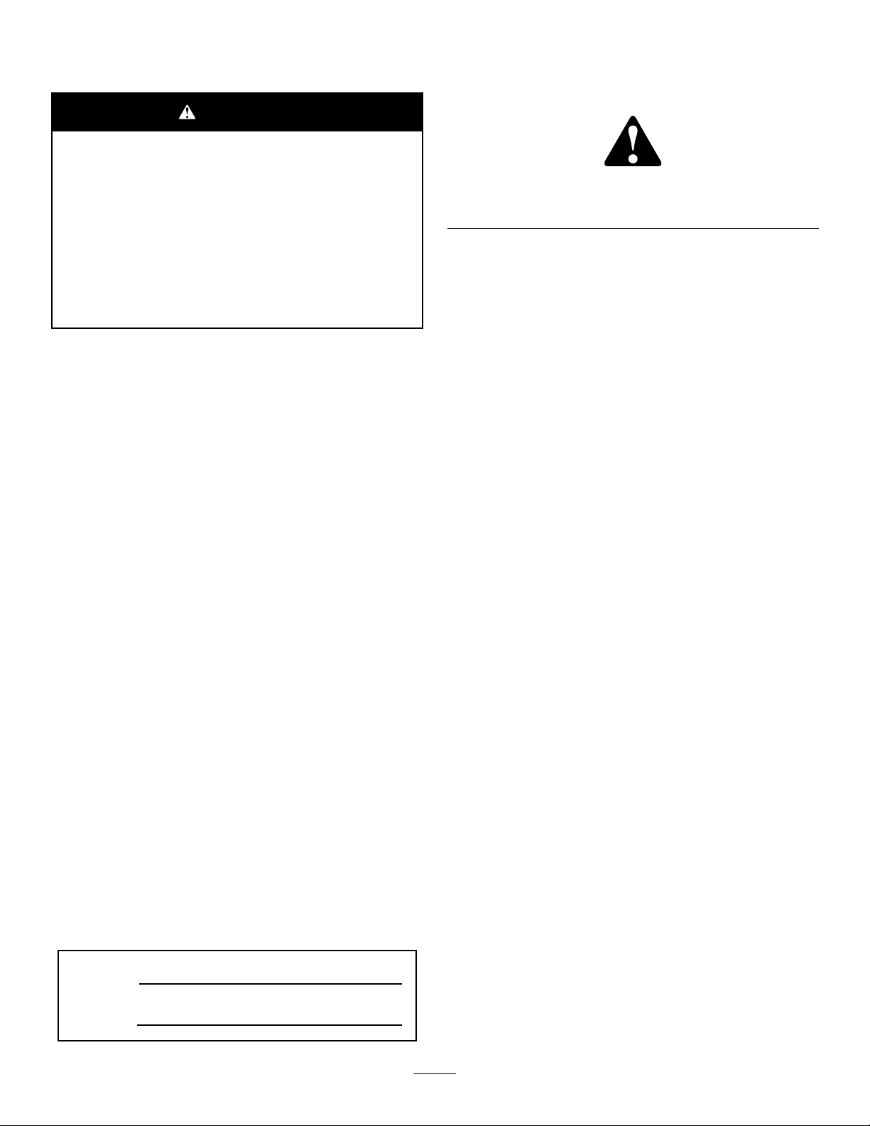
SafetyandInstructionalDecals
Safetydecalsandinstructionsareeasilyvisibleandarelocatednearanyareaofpotentialdanger.Replace
anydecalthatisdamagedorlost.
93–6689
1.Danger—donotsitontheplasticshroud.
106-6755
93-7272
1.Cutting/dismembermenthazard;fan—stayawayfrom
movingparts.
93-7818
1.Warning—readtheOperator'sManualforinstructionson
torquingthebladebolt/nutto1 15to149N∙m(85to110
ft-lb).
1.Enginecoolantunder
pressure.
2.Explosionhazard—read
theOperator'sManual.
3.Warning—donottouchthe
hotsurface.
4.Warning—readthe
Operator'sManual.
110-0986
1.Pressthebrakepedalandparkingbrakepedaltosetthe
parkingbrake.
2.Pressthebrakepedaltoapplythebrake.
3.Pressthetractionpedaltomovethemachineforward.
4.Reelenabledmode
5.Transportmode
106-6754
1.Warning—donottouchthehotsurface.
2.Cutting/dismembermenthazard,fanandentanglement
hazard,belt—stayawayfrommovingparts.
5
Page 6

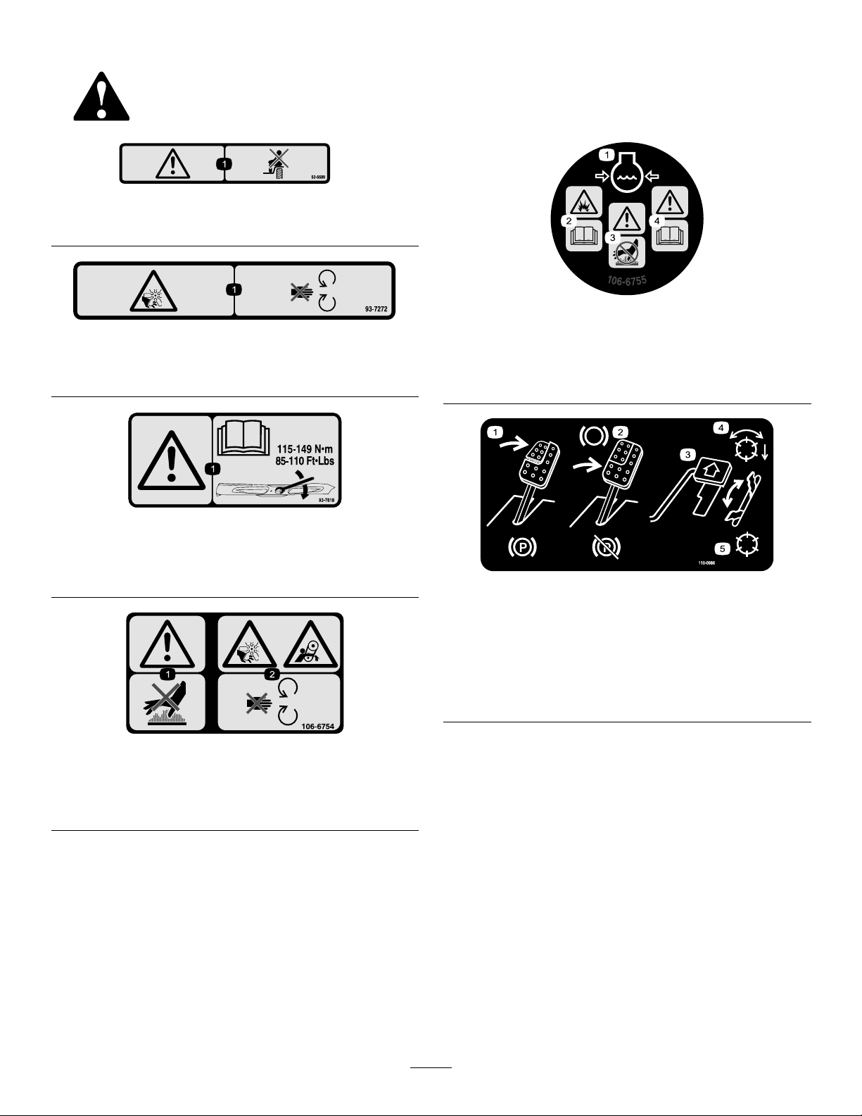
110-8869
1.Warning—readtheOperator'sManual,donotoperatethis
machineunlessyouaretrained.
2.Thrownobjecthazard—keepbystandersasafedistance
fromthemachine.
3.Tippinghazard—slowmachinebeforeturning,donotturn
athighspeeds;lowerthecuttingunitwhendrivingdown
slopes;usearolloverprotectionsystemandweartheseat
belt.AlwayswearaseatbeltwhenaROPSisinplace.
4.Warning—donotparkthemachineonslopes;engagethe
parkingbrake,lowerthecuttingdecks,stoptheengine,and
removetheignitionkeybeforeleavingthemachine.
5.Warning—readtheOperator'sManual,donottowthe
machine.
110-8921
110-8973
(AfxoverPartNumber1 10–8869forCE*)
*Thissafetydecalincludesaslopewarningrequiredonthemachinefrocomplianceto
theEuropeanLawnMowerStandardENISO5395:2013.Theconservativemaximum
slopeanglesindicatedforoperationofthismachineareprescribedbyandrequiredby
thisstandard.
1.Warning—readtheOperator'sManual,donotoperatethis
machineunlessyouaretrained.
2.Thrownobjecthazard—keepbystandersasafedistance
fromthemachine.
3.Tippinghazard—donotoperateonslopesgreaterthan15°;
lowerthecuttingdeckswhenoperatingonslopes;wear
thesafetybelt.
4.Warning—donotparkthemachineonslopes;engagethe
parkingbrake,lowerthecuttingdecks,stoptheengine,and
removetheignitionkeybeforeleavingthemachine.
5.Warning—readtheOperator'sManualbeforetowingthe
machine.
1.Tractionunitspeed
2.Slow
3.Fast
117–0169
1.ReadtheOperator'sManual.
2.Powerpoint—10A
3.Headlights—10A
4.Power—10A
5.Enginestart—15A
6.Optionalairrideseatsuspension—20A
7.EnginecomputermanagementC—7.5A
8.EnginecomputermanagementB—7.5A
9.EnginecomputermanagementA—7.5A
6
Page 7
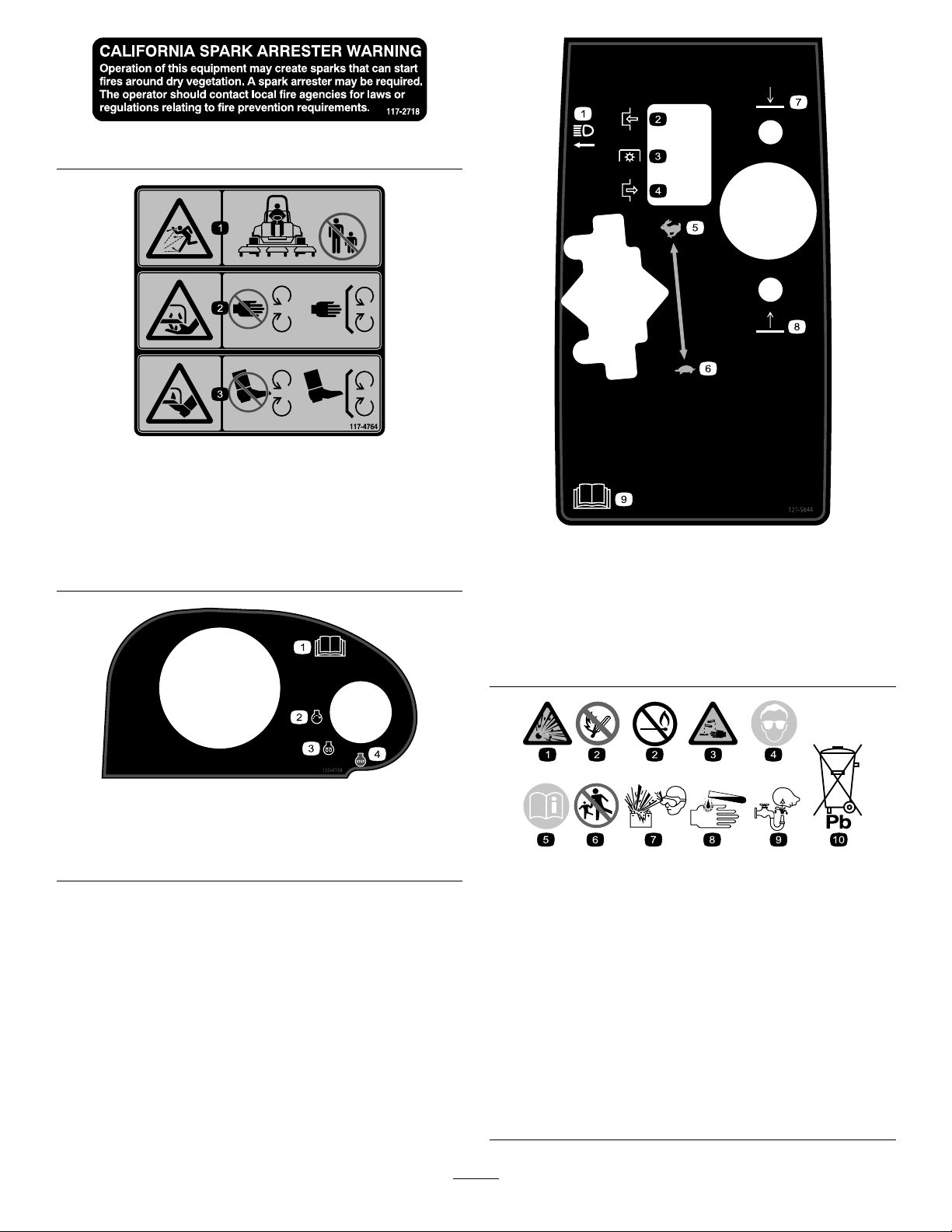
117–2718
117-4764
1.Thrownobjecthazard—keepbystandersasafedistance
fromthemachine.
2.Cuttinghazardofhand,mowerblade—stayawayfrom
movingparts,keepallguardsandshieldsinplace.
3.Cuttinghazardoffoot,mowerblade—stayawayfrom
movingparts,keepallguardsandshieldsinplace.
121–5644
1.Lightswitch
2.Engage7.Lower
3.Powertake-off
4.Disengage
5.Fast
6.Slow
8.Raise
9.ReadtheOperator’s
Manual.
1.ReadtheOperator’s
Manual.
2.Engine—start4.Engine—stop
120–4158
3.Engine—preheat
BatterySymbols
Someorallofthesesymbolsareonyourbattery
1.Explosionhazard
2.Nore,opename,or
smoking.
3.Causticliquid/chemical
burnhazard
4.Weareyeprotection.9.Flusheyesimmediately
5.ReadtheOperator's
Manual.
6.Keepbystandersasafe
distancefromthebattery.
7.Weareyeprotection;
explosivegasescan
causeblindnessandother
injuries.
8.Batteryacidcancause
blindnessorsevereburns.
withwaterandgetmedical
helpfast.
10.Containslead;donot
discard.
7
Page 8
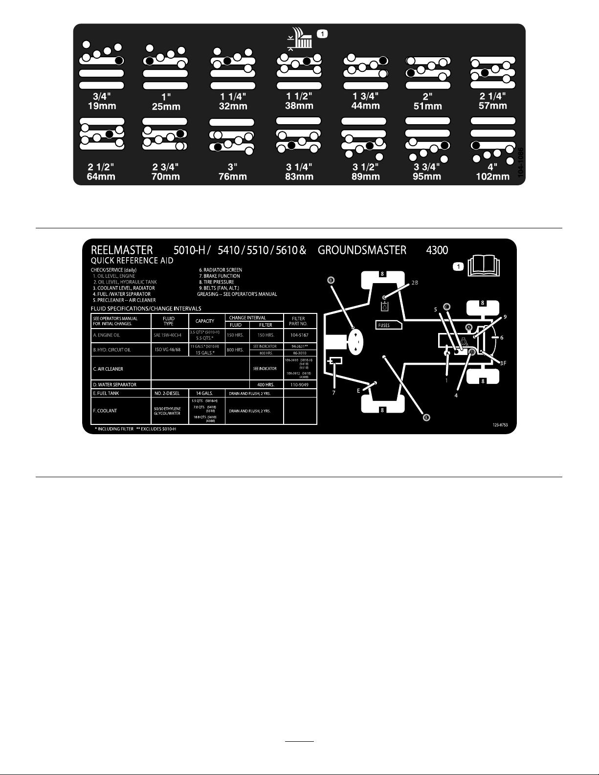
1.Heightofcut
1.ReadtheOperator'sManualformoremaintenanceinformation.
104-1086
125-8753
8
Page 9

Setup
LooseParts
Usethechartbelowtoverifythatallpartshavebeenshipped.
ProcedureDescription
1
2
3
4
5
6
7
8
9
MediaandAdditionalParts
Nopartsrequired
Nopartsrequired
Rearweights(quantityvarieswith
conguration).
Hoodlatchassembly1
Washer1
Throttlestop1
Setscrew
Nopartsrequired
Nopartsrequired
Nopartsrequired
Nopartsrequired
Varies
Qty.
Use
–
–
1
–
–
–
–
Adjustthecontrolarmposition.
Removetheshippingblocksandpins.
Installrearweights(orderfromyour
ToroDistributor).
InstallthehoodlatchforCEcompliance.
InstallthethrottlestopforCE
compliance.
Adjustthecarrierframe.
Adjusttherollerscraper(Optional).
Installthemulchingbafe(Optional).
Preparethemachine.
Description
Operator'sManual
EngineOperator'sManual
PartsCatalog
DeclarationofConformity
OperatorTrainingMaterial
Note:Determinetheleftandrightsidesofthemachine
fromthenormaloperatingposition.
Qty.
Use
1
1
1
1
1
Reviewbeforeoperatingmachine
9
Page 10
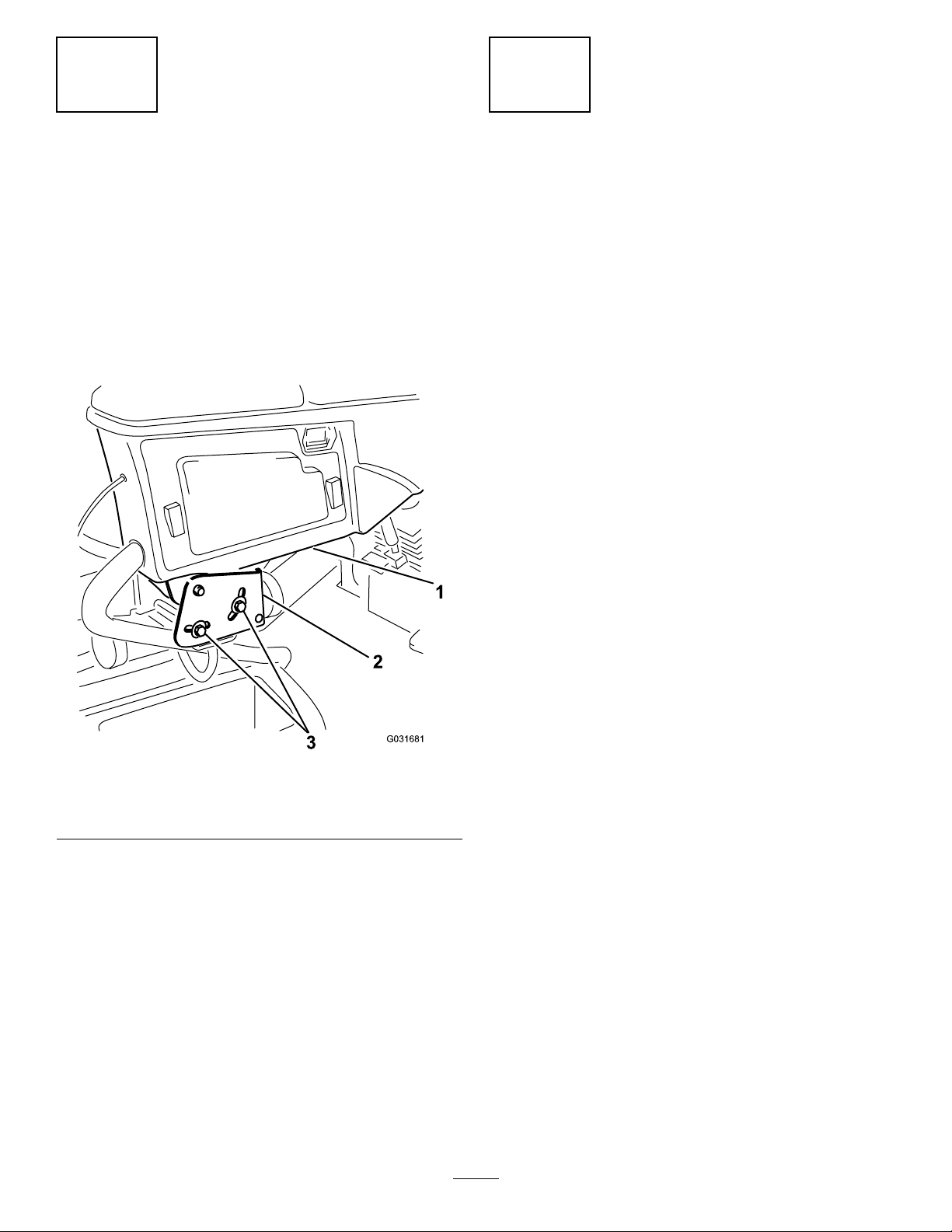
1
2
AdjustingtheControlArm Position
NoPartsRequired
Procedure
Thecontrolarmpositioncanbeadjustedfortheoperator’s
comfort.
1.Loosenthe2boltssecuringthecontrolarmtothe
retainingbracket(Figure2).
RemovingtheShippingBlocks andPins
NoPartsRequired
Procedure
1.Removeanddiscardtheshippingblocksfromthe
cuttingdecks.
2.Removeanddiscardtheshippingpinsfromthe
cutting-decksuspensionarms.
Important:Theshippingpinsstabilizethecutting
decksduringshipping,removethembeforeoperation.
Figure2
1.Controlarm3.Bolts(2)
2.Retainingbrackets
2.Rotatethecontrolarmtothedesiredpositionand
tightenthe2bolts.
10
Page 11
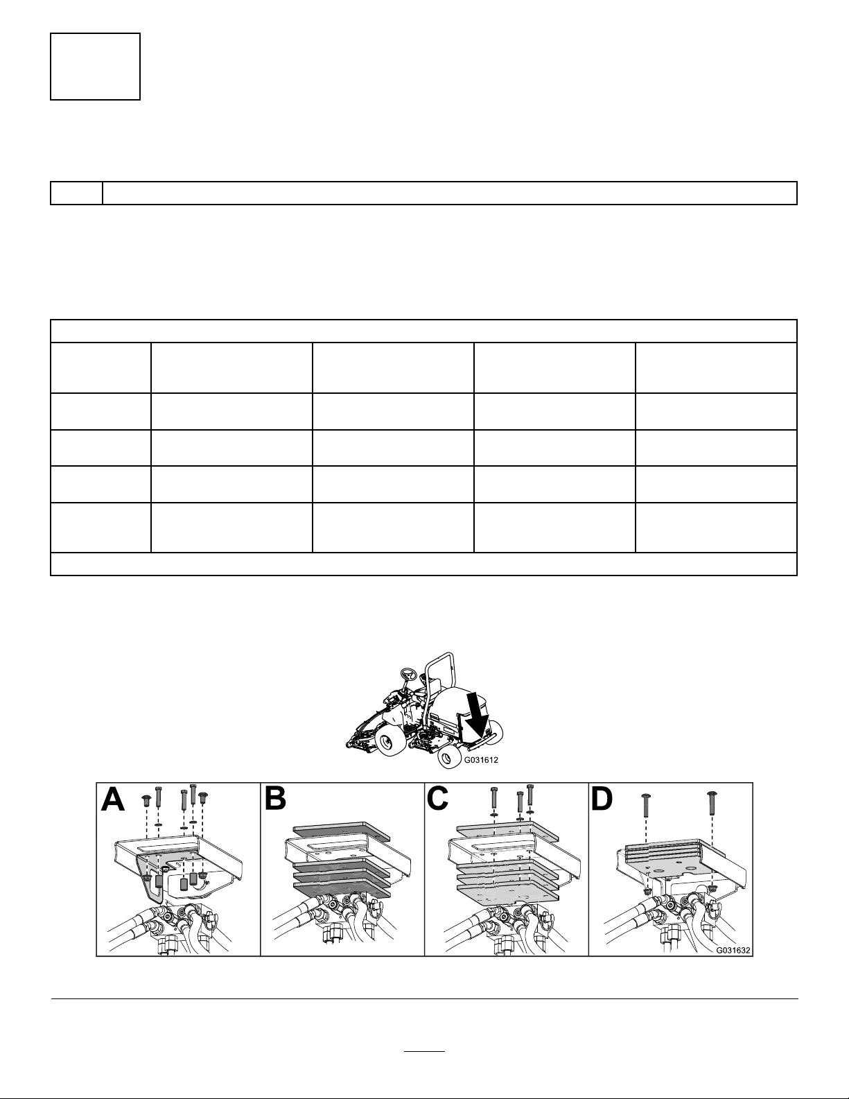
3
InstallingRearWeights
Partsneededforthisprocedure:
Varies
Rearweights(quantityvarieswithconguration).
Procedure
TheGroundsmaster4300–DTractionUnitcomplieswithENISO5395:2013andANSIB71.4-2012standardswhenequipped
withrearweightsand/or40.8kg(90lb)ofcalciumchlorideballastisaddedtorearwheels.Usethefollowingchartsto
determinethecombinationsofweightsrequiredforyourconguration.OrderpartsfromyourT oroDistributor.
WeightP/N110-8985-03
Conguration
BaseUnit60
WithRecycler
Kit
With
Sunshade
With4Post
ROPS&
Sunshade
Numberofweights
tomeetANSI(US)
standards
40.8kg(90lb)calcium
chloride*
40.8kg(90lb)calcium
chloride*
40.8kg(90lb)calcium
chloride*
*Installtubesinsidethereartiresbeforeaddingcalciumchloride.
Numberofweightsto
meetCE(European)
standards
0
4
4
Fasteners(2each
required)forweights
3231–34CarriageBolt
104–8301Nut
N/AN/A
3231–7CarriageBolt
104–8301Nut
3231–7CarriageBolt
104–8301Nut
WeightLocation
3ontopofbumperand
3underbumper
1ontopofbumperand
3underbumper
1ontopofbumperand
3underbumper
Important:Alwaysinstalltubesinsidethereartiresbeforecalciumchlorideisinstalled.Ifapunctureoccursina
tirewithcalciumchloride,removethemachinefromtheturfareaasquicklyaspossible.Topreventpossibledamage
totheturf,immediatelysoaktheaffectedareawithwater.
Figure3
11
Page 12

4.Outsidethehood,insertthehookendofthelatch
throughtheholeinthehoodandmakesurethatthe
4
rubber-sealingwasherremainstotheoutersideofthe
hood(Figure5).
InstallingtheHoodLatchfor CECompliance
Partsneededforthisprocedure:
1Hoodlatchassembly
1Washer
Procedure
1.Unlatchandraisethehood.
2.Removetherubbergrommetfromtheholeintheleft
sideofthehood(Figure4).
5.Insidethehood,insertthemetalwasherontothelatch
andsecurewiththenutandmakesurethatthelatch
engagestheframecatchwhenitislocked.Usethe
enclosedhood-latchkeytooperatethehoodlatch.
5
InstallingtheThrottleStopfor CECompliance
Partsneededforthisprocedure:
1Throttlestop
1
Setscrew
Procedure
1.Loosenthesetscrewonthethrottlestop(Figure6).
2.Slidethethrottlestopontothehigh-idlestopscrew
(Figure6).Thechamferedendofthethrottlestopis
tobepositionedoutward.
Figure4
1.Rubbergrommet
3.Removethenutfromthehoodlatchassembly(Figure
5).
Figure5
1.Hoodlatch3.Rubberwasher
2.Nut4.Metalwasher
Figure6
1.Throttlestop
3.TurnthekeyintheignitionswitchtotheONposition
andallowtheenginetorunfor5to10minutes.
4.Adjustthehighidleto2860rpmwiththecuttingdecks
disengaged.
5.Tightenthesetscrew.
6.Applyadhesiveintothesetscrewtopreventtampering.
12
2.Setscrew
Page 13
6
G011346
1
2
3
AdjustingtheCarrierFrame
NoPartsRequired
AdjustingtheFrontCuttingDecks
Thefrontandrearcuttingdecksrequiredifferentmounting
positions.Thefrontcuttingdeckhas2mountingpositions
dependingonwhatheightofcutanddegreeofdeckrotation
youdesire.
1.Forheightsofcutbetween2.0to7.6cm(0.75to3
inches),mountthefrontcarrierframesinthelower
frontmountingholes(Figure7).
AdjustingtheRearCuttingDeck
Thefrontandrearcuttingdecksrequiredifferentmounting
positions.Therearcuttingdeckhas1mountingpositionfor
properalignmentwiththesidewinderunderframe.
Forallheightsofcut,mounttherearcuttingdeckinthe
rear-mountingholes(Figure7).
7
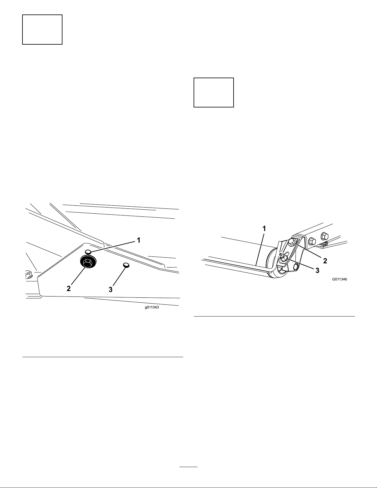
AdjustingtheRollerScraper (Optional)
NoPartsRequired
Note:Thispermitsmoreuptravelofthecutting
decksrelativetotractorwhenapproachingquickuphill
changesinterrain.Itdoeshoweverlimittheclearance
ofthechambertothecarrierwhencrestingsharp
knolls.
Figure7
1.Frontdeckmountinghole
(upper)
2.Frontdeckmountinghole
(lower)
2.Forheightsofcutbetween6.3to10cm(2.5to4
inches),mountthefrontcarrierframesintheupper
frontmountingholes(Figure7).
3.Reardeckmountinghole
Procedure
Theoptionalrearrollerscraperisdesignedtoworkbestwhen
thereisanevengapof0.5to1mm(0.020to0.040inch)
betweenthescraperandroller.
1.Loosenthegreasettingandthemountingscrew
(Figure8).
Figure8
1.Rollerscraper
2.Mountingscrew
2.Slidethescraperupordownuntilagapof0.5to1
mm(0.020to0.040inch)isachievedbetweentherod
andtheroller.
3.Securethegreasettingandtorqueto41N∙m(30ft-lb)
inanalternatingsequence.
3.Greasetting
Note:Thisincreasesthechambertocarrierclearance
duetothehigherpositionofthecuttingchamber,but
willcausethecuttingdeckstoreachtheirmaximum
uptravelsooner.
13
Page 14
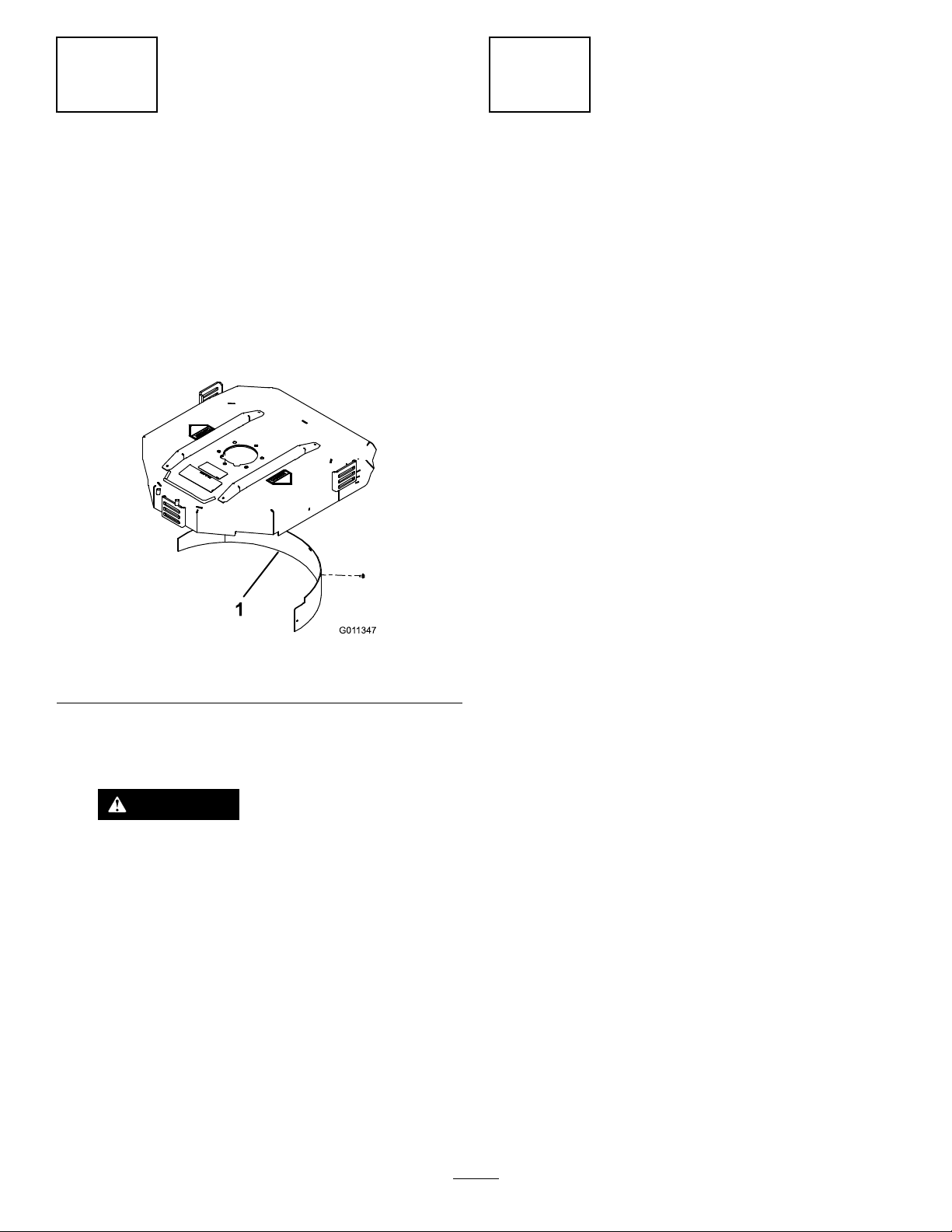
8
G011347
1
9
InstallingtheMulchingBafe
(Optional)
NoPartsRequired
Procedure
1.Thoroughlycleandebrisfromthemountingholeson
therearwallandleftsidewallofthechamber.
2.Installthemulchingbafeintherearopeningand
secureitwith5ange-headbolts(Figure9).
PreparingtheMachine
NoPartsRequired
CheckingtheTirePressure
Checkthetirepressurebeforeuse;refertoCheckingtheTire
Pressure(page22).
Important:Maintainpressureinalltirestoensurea
goodquality-of-cutandpropermachineperformance.
Do not underinate the tir es.
CheckingtheFluidLevels
1.Checktheengine-oillevelbeforestartingtheengine;
refertoCheckingtheEngine-OilLevel(page38).
2.Checkthehydraulic-uidlevelbeforestartingthe
engine;refertoCheckingtheHydraulicFluidLevel
(page47).
3.Checkthecoolingsystembeforestartingtheengine;
refertoCheckingtheCoolingSystem(page44).
Figure9
1.Mulchingbafe
3.Verifythatthemulchingbafedoesnotinterferewith
thetipofthebladeanddoesnotprotrudeinsidethe
surfaceoftherearchamberwall.
DANGER
Donotusethehigh-liftbladewiththe
mulchingbafe.Thebladecouldbreak,
resultinginpersonalinjuryordeath.
GreasingtheMachine
Greasethemachinebeforeuse;refertoGreasingtheBearings
andBushings(page35).Failuretoproperlygreasethe
machineresultsinprematurefailureofcriticalparts.
14
Page 15
ProductOverview
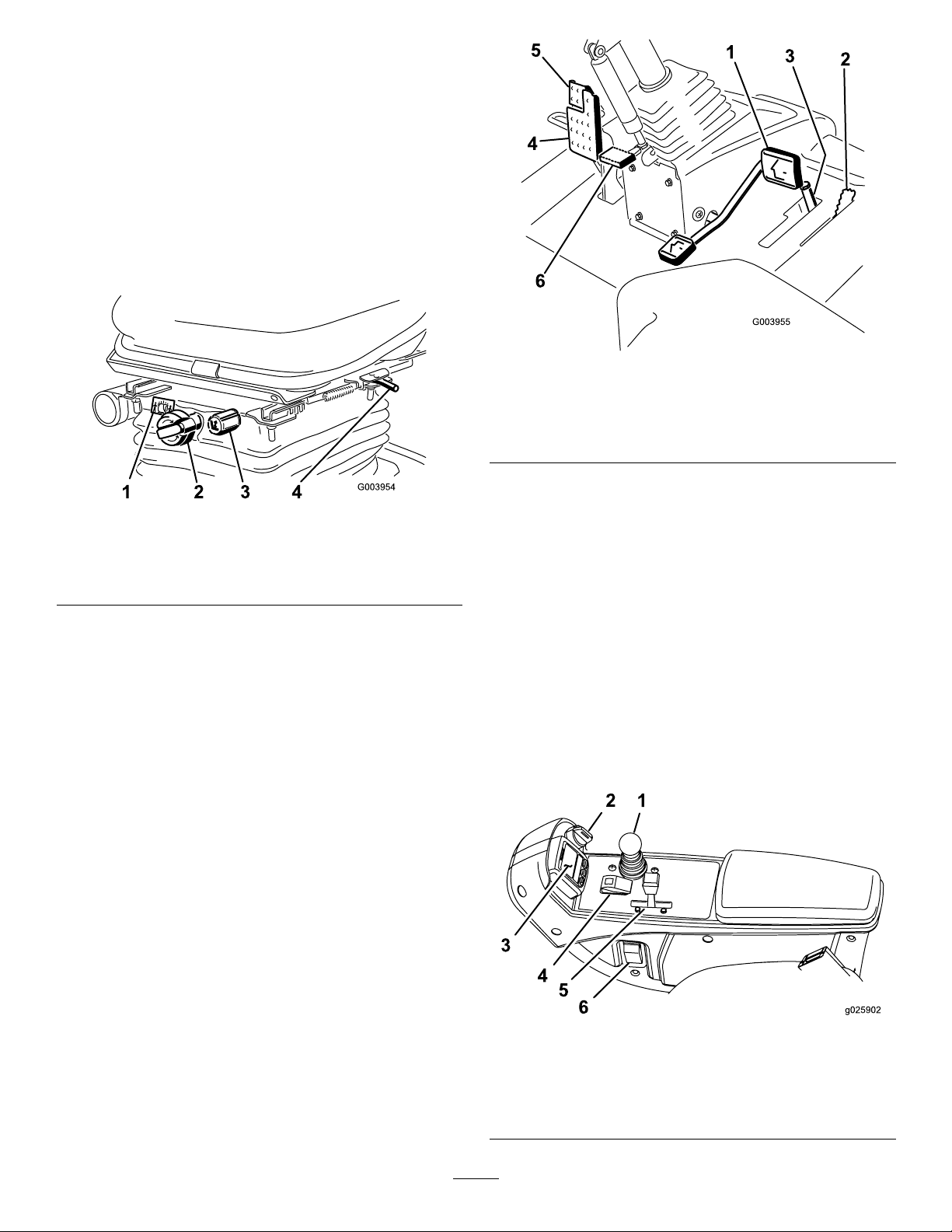
Controls
Seat-AdjustingKnobs
Theseat-adjustinglever(Figure10)allowsyoutoadjustthe
seatforeandaft.Theweight-adjustingknobadjuststhe
seatfortheoperator’sweight.Theweightgaugeindicates
whentheseatisadjustedtotheoperator’sweight.The
height-adjustingknobadjuststheseatfortheoperator’s
height.
Figure11
1.Tractionpedal4.Brakepedal
2.Mow-speedlimiter5.Parkingbrake
3.Spacers
6.Tilt-steeringpedal
Figure10
1.Weightgauge3.Height-adjustingknob
2.Weight-adjustingknob
4.Adjustinglever(foreand
aft)
TractionPedal
Thetractionpedal(Figure11)controlstheforwardand
reverseoperation.Pressthetopofthepedaltomoveforward
andthebottomtomovebackward.
Tostop,reducefootpressureonthetractionpedalandallow
ittoreturntothecenterposition.
Mow-SpeedLimiter
Whenthemow-speedlimiter(Figure11)isippedupitwill
controlthemowspeedandallowthecuttingdeckstobe
engaged.Eachspaceradjuststhemowingspeedby0.8km/h
(0.5mph).Themorespacersyouhaveonthetopofthebolt,
thesloweryouwillgo.Fortransport,ipbackthemowspeed
limiterformaximum-transportspeed.
Tilt-SteeringPedal
Totiltthesteeringwheeltowardsyou,pressthefootpedal
(Figure11)down,andpullthesteeringtowertowardyouto
themostcomfortablepositionandthenreleasethepedal.
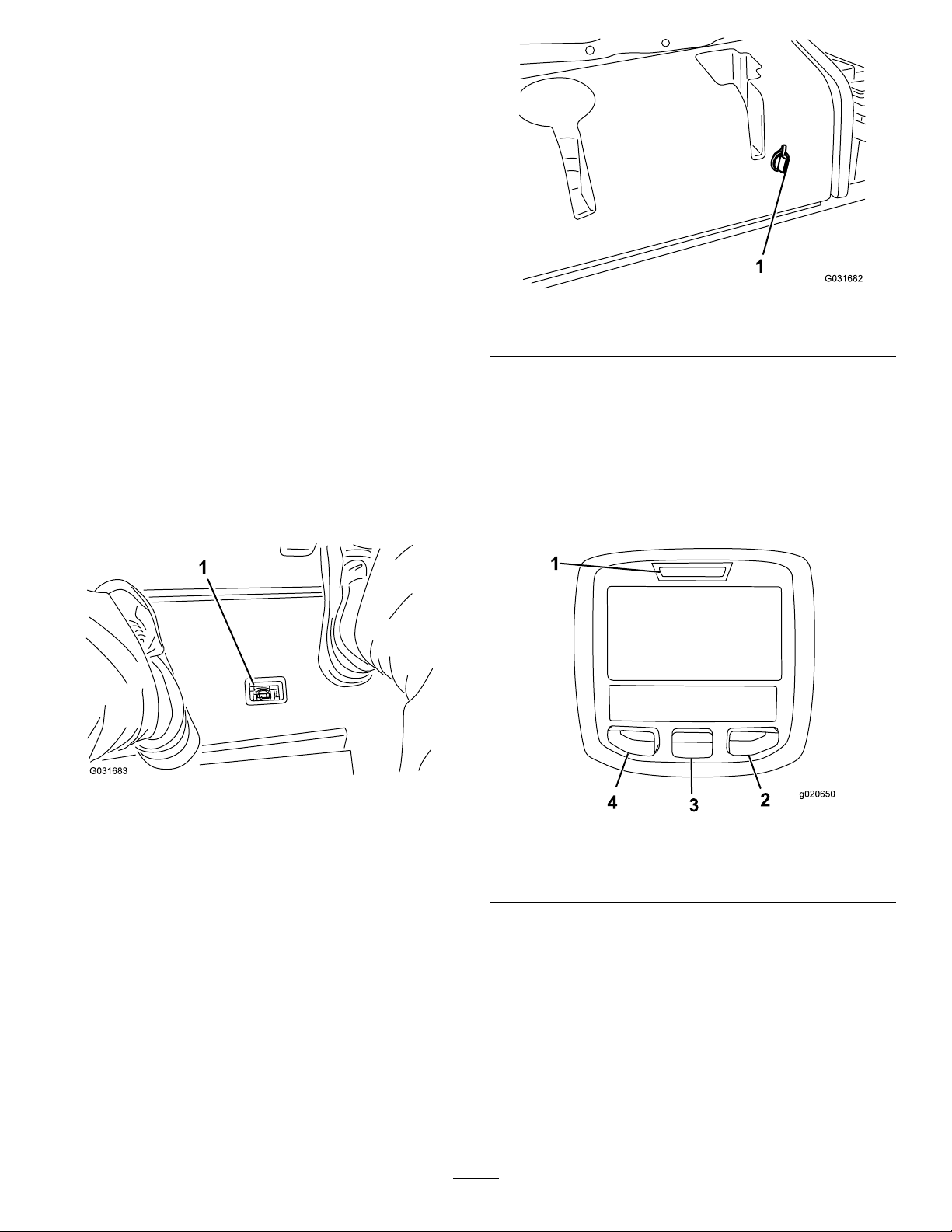
HeadlightSwitch
Pivottheswitchdownwardtoturnontheheadlights
(Figure12).
ThrottleControl
Movethethrottlecontrol(Figure12)forwardtoincreasethe
enginespeedandbackwardtodecreasespeed.
BrakePedal
Pressthebrakepedal(Figure11)tostopthemachine.
ParkingBrake
Toengagetheparkingbrake,(Figure11)pushdownonthe
brakepedalandpressthetopforwardtolatch.Toreleasethe
parkingbrake,pressthebrakepedaluntiltheparking-brake
latchretracts.
Figure12
1.Lowermow/raisecontrol
lever
2.Keyswitch5.Throttlecontrol
3.InfoCenter
15
4.Enable/disableswitch
6.Headlightswitch
Page 16
KeySwitch
1
g020650
2
3
4
TORO
Thekeyswitch(Figure12)has3positions:OFF,
ON/PREHEAT,andSTART.
LowerMow/RaiseControlLever
Thislever(Figure12)raisesandlowersthecuttingdecks
andalsostartsandstopsthemowerswhenthemowersare
enabledinthemowmode.Whenstartingthedecksinthe
downposition,thisleverwillturnthedecksonifthePTO
andthemowspeedlimiterareengaged.
Enable/DisableSwitch
Usetheenable/disableswitch(Figure12)inconjunctionwith
thelowermow/raisecontrollevertooperatethemowers.
Themowerscannotbeloweredwhenthemow/transport
leverisinthetransportposition.
Hydraulic-Filter-RestrictionIndicator
Withtheenginerunningatnormaloperatingtemperature,
viewtheindicator(Figure13),itshouldbeinthegreenzone.
Whentheindicatorisintheredzone,changethehydraulic
lters.
Figure14
1.Powerpoint
UsingtheInfoCenterLCDDisplay
TheInfoCenterLCDdisplayshowstheoperatingstatus,
variousdiagnostics,andotherinformationaboutthemachine
(Figure15).Thereisasplashscreenandmaininformation
screenintheInfoCenter.PressanyoftheInfoCenterbuttons
andthenselecttheappropriatedirectionalarrowtoswitch
betweenthesplashscreenandthemaininformationscreen.
Figure13
1.Hydraulic-lter-restrictionindicator
1.Indicatorlight3.Middlebutton
PowerPoint
Thepowerpointisa12Vpowersupplyforelectronicdevices
(Figure14).
2.Rightbutton
•LeftButton,MenuAccess/BackButton—presstoaccess
theInfoCentermenus.Youcanuseittobackoutofany
menuyouarecurrentlyusing.
•MiddleButton—presstoscrolldownmenus.
•RightButton—presstoopenamenuwherearightarrow
indicatesadditionalcontent.
Note:Thepurposeofeachbuttonmaychangedepending
onwhatisrequiredatthetime.Eachbuttonislabeledwith
anicondisplayingitscurrentfunction.
16
Figure15
4.Leftbutton
Page 17

InfoCenterIconDescription
SERVICEDUE
Indicateswhenscheduledservice
shouldbeperformed
Hourmeter
InfoCenterIconDescription(cont'd.)
Cuttingunitsarelowering.
Infoicon
Fast
Slow
Fuellevel
Theglowplugsareactive.
Raisethecuttingunits.
Lowerthecuttingunits.
Sitintheseat.
TheparkingbrakeisOn.
Therangeishigh(Transport).
Neutral
Cuttingunitsareraising.
PINpasscode
CANbus
InfoCenter
Badorfailed
Bulb
OutputofTECcontrollerorcontrol
wireinharness
Switch
Releasetheswitch.
Changetoindicatedstate.
Symbolsareoften
combinedtoform
sentences.Some
examplesareshown
below
Putmachineintoneutral.
Therangeislow(Mow).
CoolantTemperature(°Cor°F)
Temperature(hot)
ThePTOisengaged
Notallowed
Starttheengine.
Stoptheengine.
Engine
Keyswitch
Enginestartisdenied.
Engineshutdown
Enginecoolantistoohot.
Sitdownorsetparkingbrake
17
Page 18

UsingtheMenus
ToaccesstheInfoCentermenusystem,pressthemenuaccess
buttonwhileatthemainscreen.Thiswillbringyoutothe
mainmenu.Refertothefollowingtablesforasynopsisof
theoptionsavailablefromthemenus:
MainMenu
MenuItemDescription
Faults
ServiceContainsinformationonthe
Diagnostics
Settings
AboutListsthemodelnumber,serial
Service
MenuItemDescription
Hours
Counts
Containsalistoftherecent
machinefaults.Referto
theServiceManualoryour
ToroDistributorformore
informationontheFaults
menuandtheinformation
containedthere.
machinesuchashoursofuse,
counters,andothersimilar
numbers.
Displaysthestateofeach
machineswitch,sensor,and
controloutput.Y oucanuse
thistotroubleshootcertain
issuesasitquicklytellsyou
whichmachinecontrolsare
ONandwhichareOFF.
Allowsyoutocustomizeand
modifycongurationvariables
ontheInfoCenterdisplay.
number,andsoftwareversion
ofyourmachine.
Liststhetotalnumberofhours
thatthemachine,engine,and
PTOhavebeenon,aswell
asthenumberofhoursthe
machinehasbeentransported
andservicedue.
Listsnumerouscountsthe
machinehasexperienced.
Settings
MenuItemDescription
Units
Language
LCDBacklightControlsthebrightnessofthe
LCDContrastControlsthecontrastofthe
ProtectedMenusAllowsthe
CounterbalanceControlstheamountof
Controlstheunitsusedonthe
InfoCenter(EnglishorMetric).
Controlsthelanguageused
ontheInfoCenter*.
LCDdisplay.
LCDdisplay.
superintendant/mechanic
toaccessprotectedmenusby
inputtingapasscode.
counterbalanceappliedtothe
cuttingdecks.
*Only"operator-faced"textistranslated.Faults,Service,and
Diagnosticsscreensare"service-faced".Titlesappearinthe
selectedlanguage,butmenuitemsareinEnglish.
About
MenuItemDescription
Model
SNListstheserialnumberofthe
MachineControllerRevisionListsthesoftwarerevisionof
InfoCenterRevisionListsthesoftwarerevisionof
CANBus
Liststhemodelnumberofthe
machine.
machine.
themastercontroller .
theInfoCenter.
Liststhemachine
communicationbusstatus.
Diagnostics
MenuItemDescription
CuttingUnitsIndicatestheinputs,qualiers,
Hi/LowRangeIndicatestheinputs,qualiers,
PTOIndicatestheinputs,qualiers,
EngineRun
andoutputsforraisingand
loweringthecuttingunits.
andoutputsfordrivingin
transportmode.
andoutputsforenablingthe
PTOcircuit.
Indicatestheinputs,qualiers,
andoutputsforstartingthe
engine.
18
Page 19

ProtectedMenus
Thereis1operatingcongurationsettingthatisadjustable
withintheSettingsMenuoftheInfoCenter:counterbalance.
ThissettingcanbelockedbyusingtheProtectedMenu.
Note:Atthetimeofdelivery,theinitialpasswordcodeis
programmedbyyourdistributor.
AccessingtheProtectedMenuSettings
1.FromtheMainMenu,scrolldowntotheSettings
Menuandpresstherightbutton.
2.IntheSettingsMenu,scrolldowntotheProtected
Menuandpresstherightbutton.
3.Toenterthepasscode,usethecenterbuttontosetthe
rstdigitandthenpresstherightbuttontomoveon
tothenextdigit.
4.Usethecenterbuttontosettheseconddigitandthen
presstherightbuttontomoveonthenextdigit.
5.Usethecenterbuttontosetthethirddigitandthen
presstherightbuttontomoveontothenextdigit.
6.Usethecenterbuttontosetthefourthdigitandthen
presstherightbutton.
7.Pressthemiddlebuttontoenterthecode.
8.Ifthecodehasbeenacceptedandtheprotectedmenu
hasbeenunlocked,“PIN”willbedisplayedinthe
upperrightcornerofthedisplayscreen.
Specications
Note:Specicationsanddesignaresubjecttochange
withoutnotice.
TransportWidth
Widthofcut229cm(90inches)
Length
Height
Netweight*1,412kg(3,114lb)
Fueltankcapacity
Transportspeed
Mowingspeed
*Withcuttingdecksanduids
CuttingDeck
Length
Width
Height
Weight
Attachments/Accessories
226cm(89inches)
320cm(126inches)
218cm(86inches)
53L(14USgallons)
0to16km/h(0to10mph)
0to13km/h(0to8mph)
86.4cm(34inches)
86.4cm(34inches)
24.4cm(9.6inches)
tocarriermount
26.7cm(10–1/2inches)
at3/4inchheightofcut
34.9cm(13–3/4inches)at
4inchheightofcut
88kg(195lb)
Note:Ifyouforgetormisplaceyourpasscode,contact
yourToroDistributorforassistance.
ViewingandChangingtheProtected
MenuSettings
1.IntheProtectedMenu,scrolldowntoProtectSettings.
2.Toviewandchangethesettingswithoutenteringa
passcode,usetherightbuttontochangetheProtect
SettingstoOFF.
3.Toviewandchangethesettingswithapasscode,use
theleftbuttontochangetheProtectSettingstoON,
setthepasscode,andturnthekeyintheignitionswitch
totheOFFpositionandthentotheONposition.
SettingtheCounterbalance
1.IntheSettingsMenu,scrolldowntoCounterbalance.
2.Presstherightbuttontoselectcounterbalanceand
changebetweenthelow ,medium,andhighsettings.
AselectionofToroapprovedattachmentsandaccessoriesis
availableforusewiththemachinetoenhanceandexpand
itscapabilities.ContactyourAuthorizedServiceDealeror
Distributororgotowww .Toro.comforalistofallapproved
attachmentsandaccessories.
Tobestprotectyourinvestmentandmaintainoptimal
performanceofyourToroequipment,countonTorogenuine
parts.Whenitcomestoreliability ,Torodeliversreplacement
partsdesignedtotheexactengineeringspecicationofour
equipment.Forpeaceofmind,insistonT orogenuineparts.
19
Page 20

Operation
FuelSafety
Note:Determinetheleftandrightsidesofthemachine
fromthenormaloperatingposition.
BeforeOperation
BeforeOperationSafety
GeneralSafety
•Neverallowchildrenoruntrainedpeopletooperateor
servicethemachine.Localregulationsmayrestrictthe
ageoftheoperator.Theownerisresponsiblefortraining
alloperatorsandmechanics.
•Becomefamiliarwiththesafeoperationoftheequipment,
operatorcontrols,andsafetysigns.Knowhowtostop
themachineandenginequickly.
•Checkthatallsafetydevicesareattachedand
functioningproperly.Thisincludes,butisnotlimitedto,
operator-presencecontrols;safetyswitchesandshields;
therolloverprotectionsystem(ROPS);attachments;and
brakes.Donotoperatethemachineunlessallsafety
devicesareinpositionandfunctioningasintendedby
themanufacturer.
•Alwaysinspectthemachinetoensurethattheblades,
bladebolts,andcuttingassemblyarenotwornor
damaged.Replacewornordamagedbladesandboltsin
setstopreservebalance.
•Inspecttheareawhereyouwillusethemachineand
removeallobjectsthatthemachinecouldpotentially
throw .
•Evaluatetheterraintodeterminetheappropriate
equipmentandanyattachmentsoraccessoriesrequiredto
operatethemachineproperlyandsafely.
DANGER
Incertainconditions,fuelisextremelyammable
andhighlyexplosive.Areorexplosionfromfuel
canburnyouandothersandcandamageproperty.
•Fillthefueltankoutdoors,inanopenarea,when
theengineiscold.Wipeupanyfuelthatspills.
•Neverllthefueltankinsideanenclosedtrailer.
•Neversmokewhenhandlingfuel,andstayaway
fromanopenameorwherefuelfumesmaybe
ignitedbyaspark.
•Storefuelinanapprovedcontainerandkeepit
outofthereachofchildren.Neverbuymore
thana180-daysupplyoffuel.
•Donotoperatethemachinewithouttheentire
exhaustsysteminplaceandinproperworking
condition.
WARNING
Fuelisharmfulorfatalifswallowed.Long-term
exposuretovaporscancauseseriousinjuryand
illness.
•Avoidprolongedbreathingofvapors.
•Keepyourhandsandfaceawayfromthenozzle
andthefuel-tankopening.
•Keepfuelawayfromyoureyesandskin.
•Useonlyanapprovedfuelcontainer.
•Neverremovethefuelcaporaddfueltothefueltank
whiletheengineisrunning.
•Neverllcontainersinsideavehicleoronatruckor
trailerbedwithaplasticliner.Alwaysplacecontainerson
thegroundandawayfromyourvehiclebeforelling.
•Removetheequipmentfromthetruckortrailerandadd
fueltoitwhileitisontheground.Ifthisisnotpossible,
thenaddfuelusingaportablecontainerratherthanfrom
afuel-dispensernozzle.
•Keepthefuel-dispensernozzleincontactwiththerimof
thefueltankorcontaineropeningatalltimesuntilfueling
iscomplete.Donotuseanozzlelock-opendevice.
•Ifyouspillfuelonyourclothing,changeyourclothing
immediately.
•Fillthefueltankuntilthefuellevelis25mm(1inch)
belowthebottomofthellerneck.Donotoverllthe
fueltank.Replacethefuel-tankcapandtightenitsecurely .
20
Page 21

CheckingtheEngine-OilLevel
Beforeyoustarttheengineandusethemachine,check
theoillevelintheenginecrankcase;refertoCheckingthe
Engine-OilLevel(page38).
•Paintedsurfacesmaybedamagedbybiodieselblends.
•UseB5(biodieselcontentof5%)orlesserblendsincold
weather.
•Monitorseals,hoses,gasketsincontactwithfuelasthey
maybedegradedovertime.
CheckingtheCoolingSystem
Beforeyoustarttheengineandusethemachine,checkthe
coolingsystem;refertoCheckingtheCoolingSystem(page
44).
CheckingtheHydraulic System
Beforeyoustarttheengineandusethemachine,checkthe
hydraulicsystem;refertoCheckingtheHydraulicLinesand
Hoses(page49).
FillingtheFuelTank
RecommendedFuel
Useonlyclean,freshdieselfuelorbiodieselfuelswithlow
(<500ppm)orultralow(<15ppm)sulfurcontent.The
minimumcetaneratingshouldbe40.Purchasefuelin
quantitiesthatcanbeusedwithin180daystoensurefuel
freshness.
•Fuellterpluggingmaybeexpectedforatimeafter
convertingtobiodieselblended.
•Contactyourdistributorifyouwishformoreinformation
onbiodiesel.
Fueltankcapacity:53L(14USgallons)
Usesummergradedieselfuel(No.2-D)attemperatures
above-7°C(20°F)andwintergrade(No.1-DorNo.
1-D/2-Dblend)belowthattemperature.Useofwintergrade
fuelatlowertemperaturesprovideslowerashpointand
coldowcharacteristicswhichwilleasestartingandreduce
fuellterplugging.
Useofsummergradefuelabove-7°C(20°F)willcontribute
towardlongerfuelpumplifeandincreasedpowercompared
towintergradefuel.
Important:Donotusekeroseneorgasolineinsteadof
dieselfuel.Failuretoobservethiscautionwilldamage
theengine.
BiodieselReady
Thismachinecanalsouseabiodieselblendedfuelofup
toB20(20%biodiesel,80%petrodiesel).Thepetrodiesel
portionshouldbeloworultralowsulfur.Observethe
followingprecautions:
•Thebiodieselportionofthefuelmustmeetspecication
ASTMD6751orEN14214.
Figure16
•TheblendedfuelcompositionshouldmeetASTMD975
orEN590.
21
Page 22

CheckingtheTirePressure
ServiceInterval:Beforeeachuseordaily
1.Lowerthecuttingdecktotheground,turnthekeyin
theignitionswitchtotheOFFposition,andremove
thekey.
Thecorrectairpressureinthefrontandreartiresis83to
103kPa(12to15psi).
Important:Maintainevenpressureinalltirestoensure
thatcontactwiththeturfisuniform.
Figure17
CheckingtheTorqueofthe Wheel-LugNuts
ServiceInterval:Afterthersthour
Aftertherst10hours
Every250hours
Torquethewheel-lugnutsto94to122N∙m(70to90ft-lb)
after1-4hoursofoperationandagainafter10hoursof
operation.Torqueevery250hoursthereafter.
2.Loosentheboltsecuringeachheight-of-cutbracketto
theheight-of-cutplate(frontandeachside)(Figure18).
3.Beginningwiththefrontadjustment,removethebolt.
Figure18
1.Height-of-cutbracket3.Spacer
2.Height-of-cutplate
4.Whilesupportingthechamber,removethespacer
(Figure19).
5.Movethechambertothedesiredheightofcutand
installthespacerintothedesignatedheight-of-cuthole
andslot(Figure19).
WARNING
Failuretomaintainthepropertorqueofthewheel
nutscouldresultinfailureorlossofawheel,and
mayresultinpersonalinjury.
Torquethefrontandrear-wheelnutsto95to122
N·m(70to90ft-lb)after10hoursofoperation.
Torquethenutsevery250hoursthereafter.
AdjustingtheHeightofCut
Important:Therotarycuttingdeckcutsapproximately
6mm(1/4inch)lowerthanareelcuttingunitwiththe
samebenchsetting.Therefore,itmaybenecessaryto
havetherotarycuttingdeck'sbenchset6mm(1/4inch)
abovethatofreelscuttinginthesamearea.
Important:Accesstotherearcuttingunitsisgreatly
improvedbyremovingthecuttingunitfromthetractor.
IftheunitisequippedwithaSidewinder®,sidewindthe
cuttingunitstotheright,removetherearcuttingunit,
andslideitouttotherightside.
Figure19
6.Positionthetappedplatein-linewiththespacer.
7.Installtheboltnger-tight.
8.Repeatsteps4through7foreachsideadjustment.
9.Tightenall3boltsto41N∙m(30ft-lb).Alwaystighten
thefrontboltrst.
Note:Adjustmentsofmorethan3.8cm(1.5inches)
mayrequiretemporaryassemblytoanintermediate
heighttopreventbinding(e.g.changingfrom3.1to7.0
cm(1.25to2.75inches)heightofcut).
22
Page 23

Breaking-intheMachine
Toensureoptimumperformanceoftheparkingbrakesystem,
burnish(break-in)thebrakesbeforeuse.Settheforward
tractionspeedto6.4km/h(4mph)tomatchthereverse
tractionspeed.(All8spacersmovedtothetopofthemow
speedcontrol.)Withtheengineathighidle,proceedforward
withthemowspeedcontrolstopengagedandridethebrake
for15seconds.Proceedbackwardatfullreversespeedand
ridethebrakefor15seconds.Repeatthis5timeswaiting
1minutebetweeneachforwardandreversecycletoavoid
overheatingthebrakes.Anadjustmenttothebrakesmaybe
requiredafterbreak-in;refertoAdjustingtheParkingBrakes
(page45).
BleedingtheFuelSystem
Youmustbleedthefuelsystembeforestartingtheengineif
anyofthefollowingsituationshaveoccurred:
•Initialstart-upofanewmachine.
•Enginehasceasedrunningduetolackoffuel.
•Maintenancehasbeenperformeduponfuelsystem
components;i.e.,lterreplaced,separatorserviced,etc.
DANGER
Undercertainconditions,dieselfuelandfuel
vaporsarehighlyammableandexplosive.Are
orexplosionfromfuelcanburnyouandothersand
cancausepropertydamage.
•Useafunnelandllthefueltankoutdoors,in
anopenarea,whentheengineisoffandiscold.
Wipeupanyfuelthatspills.
Figure20
1.Bleedscrew
4.TurnthekeyintheignitionswitchtotheONposition.
Theelectricfuelpumpwillbeginoperation,thereby
forcingairoutaroundtheairbleedscrew .Leavethe
keyintheONpositionuntilasolidstreamoffuelows
outaroundthescrew .
5.TightenthescrewandturnthekeytotheOFFposition.
Note:Normally,theengineshouldstartaftertheabove
bleedingproceduresarefollowed.However,ifenginedoes
notstart,airmaybetrappedbetweeninjectionpumpand
injectors;refertoBleedingAirfromtheFuelInjectors(page
41).
•Donotllthefueltankcompletelyfull.Add
fueltothefueltankuntilthelevelis6to13mm
(0.25to0.50inch)belowthebottomoftheller
neck.Thisemptyspaceinthetankallowsthe
fueltoexpand.
•Neversmokewhenhandlingfuel,andstayaway
fromanopenameorwherefuelfumesmaybe
ignitedbyaspark.
•Storefuelinaclean,safety-approvedcontainer
andkeepthecapinplace.
1.Settheparkingbrake,turnthekeyintheignition
switchtotheOFFposition,parkthemachineonalevel
surface,andensurethatthefueltankisatleasthalffull.
2.Openthehood.
3.Opentheair-bleedscrewonthefuelinjectionpump
(Figure20)witha12mmwrench.
23
Page 24

CheckingtheInterlock Switches
Note:Makesurethatthedecksareloweredontoaclean
sectionofturforhardsurfacetoavoidthrowndustand
debris.
ServiceInterval:Beforeeachuseordaily
CAUTION
Ifsafetyinterlockswitchesaredisconnectedor
damagedthemachinecouldoperateunexpectedly
causingpersonalinjury.
•Donottamperwiththeinterlockswitches.
•Checktheoperationoftheinterlockswitches
dailyandreplaceanydamagedswitchesbefore
operatingthemachine.
Theinterlockswitchesstopthemachinewhentheoperator
getsofftheseatwhenthetractionpedalisdepressed.
However,theoperatormaygetofftheseatwhiletheengine
isrunningandthetractionpedalisintheNEUTRALposition.
AlthoughtheenginecontinuestorunifthePTOswitchis
disengagedandthetractionpedalisreleased,itisstrongly
recommendedthattheenginebestoppedbeforerisingfrom
theseat.
Tochecktheoperationoftheinterlockswitches,perform
thefollowingprocedure:
1.Parkthemachineonalevelsurface,lowerthecutting
unit,stoptheengine,andsettheparkingbrake.
2.Pressthetractionpedal.Turnthekeyintheignition
switchtotheONposition.
Note:Iftheenginecranks,thereisamalfunctionin
theinterlocksystem.Correctthismalfunctionbefore
operatingthemachine.
3.TurnthekeyintheignitionswitchtotheONposition,
risefromtheseat,andmovethePTOswitchtothe
ONposition.
Note:ThePTOshouldnotengage.IfthePTO
engages,thereisamalfunctionintheinterlocksystem.
Correctthismalfunctionbeforeoperatingthemachine.
4.Engagetheparkingbrake,turnthekeyintheignition
switchtotheONposition,starttheengine,andmove
thetractionpedaloutoftheNEUTRALposition.
Note:TheInfoCenterdisplays"tractiondenied"and
themachineshouldnotmove.Ifthemachinedoes
move,thereisamalfunctionintheinterlocksystem.
Correctthismalfunctionbeforeoperatingthemachine.
1.Haveasecondpersonstandbackfromthedeckat
least6m(20feet)andwatchthebladeson1ofthe
cuttingdecks.
2.Shutthecuttingdecksdownandrecordthetimeit
takesforthebladestocometoacompletestop.
Note:Ifthistimeisgreaterthan7seconds,the
brakingvalveneedsadjustment.CallyourToro
Distributorforassistanceinmakingthisadjustment.
SelectingaBlade
StandardCombinationSail
Thisbladewasdesignedtoprovideexcellentliftand
dispersioninalmostanycondition.Ifmoreorlessliftand
dischargevelocityisrequired,consideradifferentblade.
Attributes:Excellentliftanddispersioninmostconditions.
AngledSail
Thebladegenerallyperformsbestinlowerheightsofcut–
1.9to6.4cm(3/4to2–1/2inches).
Attributes:
•Dischargeremainsmoreevenatlowerheightsofcut.
•Dischargehaslesstendencytothrowleftandthusa
cleanerlookaroundbunkersandfairways.
•Lowerpowerrequirementatlowerheightsanddenseturf.
HighLiftParallelSail
Thebladegenerallyperformsbetterinthehigherheightsof
cut–7to10cm(2to4inches).
Attributes:
•Moreliftandhigherdischargevelocity.
•Sparseorlimpturfispickedupsignicantlyathigher
heightsofcut.
•Wetorstickyclippingsaredischargedmoreefciently
reducingcongestioninthedeck.
•Requiresmorehorsepowertorun.
CheckingtheBladeStopping Time
ServiceInterval:Beforeeachuseordaily
Thebladesofthecuttingdeckshouldcometoacomplete
stopinapproximately5secondsafteryoushutdownthe
cutting-deck-engagementswitch.
•Tendstodischargefurtherleftandcantendtowindrow
atlowerheightsofcut.
WARNING
Donotusethehigh-liftbladewiththemulching
bafe.Thebladecouldbreak,resultinginpersonal
injuryordeath.
24
Page 25

AtomicBlade
g021272
TORO
Thisbladewasdesignedtoprovideexcellentleafmulching.
Attributes:Excellentleafmulching
TheDiagnosticLight
Themachineisequippedwithadiagnosticlightwhich
indicatesifthemachinedetectsamalfunction.Thediagnostic
lightislocatedontheInfoCenter,abovethedisplayscreen
(Figure21).Whenthemachineisfunctioningproperlyand
thekeyintheignitionswitchisturnedtotheON/RUN
position,thediagnosticlightwillturnonbrieytoindicatethe
lightisworkingproperly.Whenamachineadvisorymessage
isdisplayed,thelightwillilluminatewhenthemessageis
present.Whenafaultmessageisdisplayed,thelightwillblink
untilthefaultisresolved.
Figure21
1.Diagnosticlight
ChangingtheCounterbalance Settings
Duringdifferenttimesofthemowingseasonorwhenturf
conditionsvary,theamountofcounterbalance(upwardlift)
requiredonthecuttingdeckscanbechangedtomeetthe
conditions.
1.Positionthemachineonalevelsurface,lowerthe
cuttingdecks,turnthekeyintheignitionswitchtothe
OFFposition,andengagetheparkingbrake.
2.TurnthekeyintheignitionswitchtotheRUNposition.
3.IntheInfoCenterSettingsMenu,scrolldownto
Counterbalance.
4.Presstherightbuttontoselectcounterbalanceand
changebetweenthelow ,medium,andhighsettings.
Note:Oncetheadjustmenthasbeencompleted,move
themachinetoatestareaandoperatethemachinewith
thenewsetting.Thenewcounterbalancedsettingmay
changetheeffectiveheightofcut.
25
Page 26

ChoosingAccessories
OptionalEquipmentCongurations
AngleSailBladeHighLiftParallelSail
GrassCutting:1.9to4.4
cm(0.75to1.75inches)
heightofcut
GrassCutting:5to6.4
cm(2.00to2.50inches)
heightofcut
GrassCutting:7to10
cm(2.75to4.00inches)
heightofcut
LeafMulchingRecommendedforuse
ProsEvendischargeatlower
ConsDoesnotliftthegrass
Recommendedinmost
applications
Recommendedforthick
orlushturf
Mayworkwellinlushturf
withthemulchingbafe
heightofcut.Cleaner
lookaroundbunkersand
fairwaysLowerpower
requirements
wellinhighheight-of-cut
applicationsWetor
stickygrasshasa
tendencytobuildupin
thechamber,leading
topoorqualityofcut
andhigherpower
requirements
Blade(Donotusewith
themulchingbafe)
Mayworkwellinlightor
sparseturf
Recommendedforlight
orsparseturf
Recommendedinmost
applications
NotAllowedUsewithcombination
Moreliftandhigher
dischargevelocity
Sparseorlimpturfis
pickedupathighheight
ofcutWetorsticky
clippingsaredischarged
efciently
Requiresmorepowerto
runinsomeapplications
Tendstowindrowat
lowerheightofcutin
lushgrassDonotuse
withthemulchingbafe
MulchingBafeRollerScraper
Hasbeenshownto
improvedispersionand
aftercutperformance
onnortherngrassesthat
arecutatleast3times
perweekandlessthan
1/3ofthegrassblade
isremoved.Donot
usewiththehighlift
parallelsailblade
sailoranglesailblade
only
Mayimprovedispersion
andappearancein
certaingrasscutting
applicationsVerygood
forleafmulching
Grasswillbuildupinthe
chamberifattemptingto
removetoomuchgrass
withbafeinplace
Canbeusedanytime
thatrollersbuildup
withgrassorlargeat
grassclumpsofgrass
areseen.Thescrapers
mayactuallyincrease
clumpingincertain
applications.
Reducesrollerbuildup
incertainapplications
26
Page 27

DuringOperation
DuringOperationSafety
GeneralSafety
•Theowner/usercanpreventandisresponsiblefor
accidentsthatmaycauseinjuriestohimself/herselfand
othersandfordamagetoproperty.
•Wearappropriateclothing,includingeyeprotection;
slip-resistant,substantialfootwear;andhearing
protection.Wearingsafetyshoesandlongpantsis
advisableandrequiredbysomelocalordinancesand
insuranceregulations.Tiebacklonghair,secureloose
clothing,anddonotwearjewelry.
•EnsurethatalldrivesareintheNEUTRALposition,the
parkingbrakeisengaged,andyouareintheoperating
positionbeforeyoustarttheengine.
•Keepallbodyparts,includinghandsandfeet,awayfrom
allmovingparts.
•Donotoperatethemachinewhileill,tired,orunderthe
inuenceofalcoholordrugs.
•Keepthedirectionofthemowerdischargeawayfrom
peopleandpets.
•Donotmowinreverseunlessitisabsolutelynecessary.If
youmustmowinreverse,lookbehindanddownforsmall
childrenbeforeandwhilemovingthemachineinreverse.
Stayalertandstopthemachineifachildentersthearea.
•Useextremecarewhenapproachingblindcorners,
shrubs,trees,orotherobjectsthatmayblockyourview.
•Donotmowneardrop-offs,ditches,orembankments.
Themachinecouldsuddenlyrolloverifawheelgoes
overtheedgeoriftheedgecavesin.
•Nevercarrypassengersonthemachine.
•Operatethemachineonlyingoodvisibilityand
appropriateweatherconditions.Donotoperatethe
machinewhenthereistheriskoflighting.
•Donotmowonwetgrass.Reducedtractioncouldcause
themachinetoslide.
•Neverraisethemowerdeckwiththebladesrunning.
•Stopthemachineandinspectthebladesafterstrikingan
objectorifthereisanabnormalvibrationinthemachine.
Makeallnecessaryrepairsbeforeresumingoperation.
•Stopthebladeswheneveryouarenotmowing,especially
whilecrossinglooseterrainsuchasgravel.
•Slowdownandusecautionwhenmakingturnsand
crossingroadsandsidewalkswiththemachine.Always
yieldtheright-of-way.
•Turnontheashingwarninglightsonthemachine
wheneveryoutravelonapublicroad,exceptwheresuch
useisprohibitedbylaw.
•Disengagethedrivetotheattachmentandshutoffthe
enginebeforeaddingfuelandadjustingtheheightofcut.
•Reducethethrottlesettingbeforestoppingtheengine
and,iftheenginehasafuel-shutoffvalve,shutoffthe
fuelwhenyouhavenishedoperatingthemachine.
•Neverrunanengineinanareawhereexhaustgasesare
enclosed.
•Neverleavearunningengineunattended.
•Beforeleavingtheoperatingposition,dothefollowing:
–Stopthemachineonlevelground.
–Disengagethepowertake-offandlowerthe
attachments.
–Settheparkingbrake.
–Shutofftheengineandremovethekey .
–Waitforallmovingpartstostop.
•Donotchangethegovernorsettingsonoroverspeed
theengine.Operatingtheengineatexcessivespeedmay
increasethepotentialforpersonalinjury.
•Donotusethemachineasatowingvehicle.
•UseaccessoriesandattachmentsapprovedbyTheToro®
Companyonly.
RolloverProtectionSystem(ROPS)
Safety
•DonotremovetheROPSfromthemachine.
•Ensurethattheseatbeltisattachedandthatyoucan
releaseitquicklyintheeventofanemergency.
•Alwayswearyourseatbelt.
•Checkcarefullyforoverheadclearances,suchasbranches,
doorways,andelectricalwires,beforedrivingthemachine
underthem.Donotcontactthem.
•KeeptheROPSinsafeoperatingconditionbythoroughly
inspectingitperiodicallyfordamageandkeepingallthe
mountingfastenerstight.
•ReplaceadamagedROPS.Donotrepairorreviseit.
•AnyalterationstoaROPSmustbeapprovedbyThe
Toro®Company.
SlopeSafety
•Slowdownthemachineanduseextracareonhillsides.
Travelintherecommendeddirectiononhillsides.Turf
conditionscanaffectthestabilityofthemachine.
•Avoidstarting,stopping,orturningthemachineona
slope.Ifthetireslosetraction,disengagetheblade(s)and
proceedslowlystraightdowntheslope.
•Donotturnthemachinesharply .Usecarewhenreversing
themachine.
•Whenoperatingthemachineonaslope,alwayskeepall
cuttingunitslowered.
•Avoidturningthemachineonslopes.Ifyoumustturn,
turnslowlyandgraduallydownhill,ifpossible.
•Useextracarewhileoperatingthemachinewith
attachments;theycanaffectthestabilityofthemachine.
27
Page 28

StartingandStoppingthe Engine
continuingoperation.Seriousdamagecouldoccurifyou
operatethemachinewithamalfunction.
Important:Y oumustbleedthefuelsystembefore
startingtheengineifyouarestartingtheengineforthe
rsttime,theenginehasstoppedduetolackoffuel,or
youhaveperformedmaintenanceonthefuelsystem;
refertoBleedingAirfromtheFuelInjectors(page41).
StartingtheEngine
1.Sitontheseat,keepyourfootoffthetractionpedalso
thatitisinNEUTRAL,engagetheparkingbrake,set
thethrottletotheFASTposition,andensurethatthe
Enable/DisableswitchisintheDISABLEposition.
2.TurnthekeyintheignitionswitchtotheON/PREHEAT
position.
Note:Anautomatictimerwillcontroltheglowplug
preheatfor6seconds.
3.Afterpreheatingtheglowplugs,turnthekeyinthe
ignitionswitchtotheSTARTposition.
4.Cranktheenginefornolongerthan15seconds.
Releasethekeywhentheenginestarts.
5.Ifadditionalpreheatingisrequired,turnthekeyin
theignitionswitchtotheOFFpositionandthento
theON/PREHEATposition.Repeatthisprocessas
required.
6.Runtheengineatlowidlespeeduntilitwarmsup.
StoppingtheEngine
1.MoveallcontrolstoNEUTRAL,settheparkingbrake,
movethethrottletotheLOWIDLEpositionandallow
theenginetoreachlowidlespeed.
Important:Allowtheenginetoidlefor5
minutesbeforeshuttingitoffafterafullload
operation.Failuretodosomayleadtotroubleon
aturbo-chargedengine.
2.TurnthekeyintheignitionswitchtotheOFFposition
andremovethekey.
Mowing
TurnthekeyintheignitionswitchtotheONposition,start
theengine,andmovethethrottletotheFASTposition.Move
theEnable/DisableswitchtotheENABLEpositionanduse
thelowermow/raiselevertocontrolthecuttingdecks.To
moveforwardandcutgrass,pressthetractionpedalforward.
Note:Allowtheenginetoidlefor5minutesbeforeshutting
itoffafterafullloadoperation.Failuretodosomayleadto
turbo-chargertrouble.
MowwhentheGrassIsDry
Moweitherinthelatemorningtoavoidthedew ,whichcauses
grassclumping,orinlateafternoontoavoidthedamage
thatcanbecausedbydirectsunlightonthesensitive,freshly
mowedgrass.
SelectingtheProperHeight-of-Cut
Setting
Removeapproximately25mm(1inch)ornomorethan1/3
ofthegrassbladewhencutting.Inexceptionallylushand
densegrassyoumayhavetoraisetheheight-of-cutsetting.
AlwaysStartMowingwithSharpBlades
Asharpbladecutscleanlyandwithouttearingorshredding
thegrassbladeslikeadullblade.Tearingandshredding
causesthegrasstoturnbrownattheedgeswhichimpairs
growthandincreasessusceptibilitytodiseases.Makesurethat
thebladeisingoodconditionandafullsailispresent.
CheckConditionofDeck
Makesurethatthecuttingchambersareingoodcondition.
Straightenanybendsinthechambercomponentstoensure
thatthecorrectbladetip/chamberclearanceismet.
OperatingTips
Familiarization
Beforemowinggrass,practiceoperatingthemachineinan
openarea.Startandstoptheengine.Operateinforward
andreverse.Lowerandraisethecuttingdecksandengage
anddisengagethemowers.Whenyoufeelfamiliarwiththe
machine,practiceoperatingupanddownslopesatdifferent
speeds.
WarningSystem
Ifawarninglightcomesonduringoperation,stopthe
machineimmediatelyandcorrecttheproblembefore
AfterOperating
Toensurethatoptimumperformanceismet,cleanthe
undersideofmowerhousing.Ifyouallowresiduetobuildup
inmowerhousing,cuttingperformancewilldecrease.
28
Page 29

Transport
G031851
MovetheEnable/DisableswitchtotheDISABLEpositionand
raisethecuttingdeckstotheTRANSPORTposition.Movethe
mow/transportlevertotheTRANSPORTposition.Becareful
whendrivingbetweenobjectssoyoudonotaccidentally
damagethemachineorcuttingdecks.Useextracarewhen
operatingthemachineonslopes.Driveslowlyandavoid
sharpturnsonslopestopreventrollingover.Lowerthe
cuttingdeckswhengoingdownhillforsteeringcontrol.
AfterOperation
AfterOperationSafety
GeneralSafety
•Cleangrassanddebrisfromthecuttingunits,drives,
mufers,andenginetohelppreventres.Cleanupoil
orfuelspills.
•Shutoffthefuelwhilestoringortransportingthe
machine.
•Disengagethedrivetotheattachmentwheneveryouare
transportingornotusingthemachine.
IdentifyingtheTie-Down Points
•Frontofthemachine—theholeintherectangularpad,
undertheaxletube,insideeachfronttire(Figure22).
Figure22
1.Fronttie-down
•Usefull-widthrampsforloadingthemachineintoa
trailerortruck.Donotexceeda15°anglebetweenthe
rampandthetrailerortruck.
•Tiethemachinedownsecurelyusingstraps,chains,cable,
orropes.Bothfrontandrearstrapsshouldbedirected
downandoutwardfromthemachine.
•Allowtheenginetocoolbeforestoringthemachinein
anyenclosure.
•Neverstorethemachineorfuelcontainerwherethereis
anopename,spark,orpilotlight,suchasonawater
heateroronotherappliances.
TowingSafety
•Towonlywithamachinethathasahitchdesignedfor
towing.Donotattachtowedequipmentexceptatthe
hitchpoint.
•Followthemanufacturer’ srecommendationforweight
limitsfortowedequipmentandtowingonslopes.On
slopes,theweightofthetowedequipmentmaycauseloss
oftractionandlossofcontrol.
•Neverallowchildrenorothersinorontowedequipment.
•Rearofthemachine—eachsideofthemachineonthe
rearframe(Figure23).
Figure23
1.Reartie-down
•Travelslowlyandallowextradistancetostopwhen
towing.
29
Page 30

PushingorTowingthe Machine
Inanemergency,themachinecanbemovedbyactuatingthe
bypassvalveinthevariabledisplacementhydraulicpumpand
pushingortowingthemachine.
Important:Donotpushortowthemachinefasterthan
3to4.8km/h(2to3mph)becauseinternaltransmission
damagemayoccur.Thebypassvalvemustbeopen
wheneverthemachineispushedortowed.
1.Thebypassvalveislocatedontheleftsideofthe
hydrostat(Figure24).Rotatethebolt1–1/2turnsto
openandallowtheoiltobypassinternally.Because
uidisbypassed,themachinecanbemovedslowly
withoutdamagingthetransmission.
1.Ifusingatrailer,connectittothetowingvehicleand
connectthesafetychains.
2.Ifapplicable,connectthetrailerbrakes.
3.Loadthemachineontothetrailerortruck.
4.Shutofftheengine,removethekey,setthebrake,and
closethefuelvalve.
5.Usethemetaltie-downloopsonthemachine(Figure
25)tosecurelyfastenthemachinetothetrailerortruck
withstraps,chains,cable,orropes.
Figure25
Figure24
1.Bypassvalve
2.Closethebypassvalvebeforestartingtheengine.
However,donotexceed7to11N∙m(5to8ft-lb)
torquetoclosethevalve.
Important:Runningtheenginewiththebypass
valveopenwillcausethetransmissiontooverheat.
TransportingtheMachine
Useaheavy-dutytrailerortrucktotransportthemachine.
Ensurethatthetrailerortruckhasallnecessarybrakes,
lighting,andmarkingasrequiredbylaw .Pleasecarefullyread
allthesafetyinstructions.Knowingthisinformationcould
helpyou,yourfamily,pets,orbystandersavoidinjury.
1.Tractionunittie-downloops
LoadingtheMachine
Useextremecautionwhenloadingthemachineontoatrailer
oratruck.1full-widthrampthatiswideenoughtoextend
beyondthereartiresisrecommendedinsteadofindividual
rampsforeachsideofthemachine(Figure26).Thelower
rearsectionofthemachineframeextendsbackbetweenthe
rearwheelsandservesasastopfortippingbackward.Having
afull-widthrampprovidesasurfacefortheframemembers
tocontactifthemachinestartstotipbackward.Ifitisnot
possibletouseonefull-widthramp,useenoughindividual
rampstosimulateafull-widthcontinuousramp.
Therampshouldbelongenoughsothattheanglesdonot
exceed15°(Figure26).Asteeperanglemaycausemower
componentstogetcaughtastheunitmovesfromtherampto
thetrailerortruck.Steeperanglesmayalsocausethemachine
totipbackward.Ifloadingonornearaslope,positionthe
trailerortrucksothatitisonthedownsideoftheslopeand
therampextendsuptheslope.Thiswillminimizetheramp
angle.Thetrailerortruckshouldbeaslevelaspossible.
WARNING
Drivingonstreetsorroadwayswithoutturnsignals,
lights,reectivemarkings,oraslow-movingvehicle
emblemisdangerousandcanleadtoaccidents
causingpersonalinjury.
Donotdrivethemachineonpublicstreetsor
roadways.
Important:Donotattempttoturnthemachinewhile
ontheramp;youmaylosecontrolanddriveofftheside.
Avoidsuddenaccelerationwhendrivinguparampand
suddendecelerationwhenbackingdownaramp.Both
maneuverscancausethemachinetotipbackward.
30
Page 31

DANGER
Loadingamachineontoatrailerortruckincreases
thepossibilityofbackwardtip-overandcouldcause
seriousinjuryordeath.
•Useextremecautionwhenoperatingamachine
onaramp.
•EnsurethattheROPSisintheuppositionwhile
usingtheseatbeltwhenloadingthemachine.
EnsurethattheROPSwillclearthetopofan
enclosedtrailer.
•Useonlyasingle,full-widthramp;donotuse
individualrampsforeachsideofthemachine.
•Ifindividualrampsmustbeused,useenough
rampstocreateanunbrokenrampsurfacewider
thanthemachine.
•Donotexceeda15°anglebetweentherampand
thegroundorbetweentherampandthetrailer
ortruck.
•Avoidsuddenaccelerationwhiledrivingthe
machineuparamp,toavoidtippingbackward.
•Avoidsuddendecelerationwhilebackingthe
machinedownaramp,toavoidtippingit
backward.
Figure26
1.Trailer
2.Full-widthramp4.Full-widthramp—side
3.Notgreaterthan15°
view
31
Page 32

Maintenance
Note:Determinetheleftandrightsidesofthemachinefromthenormaloperatingposition.
RecommendedMaintenanceSchedule(s)
MaintenanceService
Interval
Afterthersthour
Aftertherst8hours
Aftertherst10hours
Aftertherst50hours
Beforeeachuseordaily
Every50hours
MaintenanceProcedure
•T orquethewheel-lugnutsto94to122N∙m(70to90ft-lb).
•Checktheconditionandtensionofthealternatorbelt.
•T orquethewheel-lugnutsto94to122N∙m(70to90ft-lb).
•Changetheengineoilandlter.
•Checktheenginerpm(idleandfullthrottle).
•Checkthetirepressure.
•Checktheoperationoftheinterlockswitches.
•Checkthebladestoppingtime
•Checktheengine-oillevel.
•Checkthelevelofcoolantintheexpansiontankandcleandebrisoffthescreen,oil
cooler,andfrontoftheradiator.
•Removedebrisfromthescreen,oilcoolers,andradiator(morefrequentlyindirty
operatingconditions).
•Checkthehydraulicuidlevel.
•Checkthehydrauliclinesandhosesforleaks,kinkedlines,loosemountingsupports,
wear,loosettings,weatherdeterioration,andchemicaldeterioration.
•Greasethebearingsandbushings.(Greasethemimmediatelyaftereverywashing
regardlessoftheintervallisted.)
•Checktheconditionofandcleanthebattery.
•Checkthebatterycableconnections.
Every100hours
Every150hours
Every200hours
Every250hours
Every400hours
Every800hours
Beforestorage
Every2years
•Inspectthecooling-systemhoses.
•Checktheconditionandtensionofthealternatorbelt.
•Changetheengineoilandlter.
•Drainmoisturefromthefuelandhydraulicuidtanks.
•T orquethewheel-lugnutsto94to122N∙m(70to90ft-lb).
•Servicetheaircleaner .(Orearlieriftheair-cleanerindicatorilluminatesred.Service
itmorefrequentlyinextremelydirtyordustyconditions.)
•Checkthefuellinesandconnectionsfordeterioration,damage,orloose
connections.(Oryearly ,whichevercomesrst).
•Replacethefuelltercanister.
•Checktheenginerpm(idleandfullthrottle).
•Drainandcleanthefueltank
•Checktherearwheeltoe-in.
•Changethehydraulicuid.
•Changethehydrauliclters(sooneriftheserviceintervalindicatorisintheredzone).
•Adjusttheenginevalves(refertotheengineoperator’smanual).
•Drainandcleanthefueltank
•Flushandreplacethecooling-systemuid.
•Drainandushthehydraulictank.
•Replaceallmovinghoses.
Refertoyourengineoperator'smanualforadditionalmaintenanceprocedures.
32
Page 33

DailyMaintenanceChecklist
Duplicatethispageforroutineuse.
Fortheweekof:
MaintenanceCheckItem
Checkthesafetyinterlockoperation.
Checkthebrakeoperation.
Checktheengineoilandfuellevel.
Drainthewater/fuelseparator.
Checktheairlterrestrictionindicator.
Checktheradiatorandscreenfordebris.
Checkunusualenginenoises.
Checkunusualoperatingnoises.
Checkthehydraulicsystemoillevel.
Checkthehydrauliclterindicator.
Checkhydraulichosesfordamage.
Checkforuidleaks.
Checkthetirepressure.
Checktheinstrumentoperation.
ChecktheHeight-of-Cutadjustment
CheckConditionofBlades
Checkallgreasettingsforlubrication.
Touch-updamagedpaint.
1.Checktheglowplugandinjectornozzlesifhardstarting,excesssmoke,orroughrunningisnoted.
1
2
3
Mon.Tues.Wed.Thurs.Fri.
Sat.Sun.
2.Checkwiththeenginerunningandtheoilatoperatingtemperature
3.Immediatelyaftereverywashing,regardlessoftheintervallisted
NotationforAreasofConcern
Inspectionperformedby:
ItemDate
1
2
3
4
5
6
7
8
Important:Refertoyourengineoperator'smanualforadditionalmaintenanceprocedures.
Note:Downloadafreecopyoftheelectricalorhydraulicschematicbyvisitingwww .Toro.comandsearchingforyour
machinefromtheManualslinkonthehomepage.
Information
33
Page 34

ServiceIntervalChart
Figure27
Premaintenance
Procedures
Pre-MaintenanceSafety
•Keepallpartsofthemachineingoodworkingcondition
andallhardwaretightened,especiallyblade-attachment
hardware.Replaceallwornordamageddecals.
•Neverallowuntrainedpersonneltoservicethemachine.
•Beforeadjusting,cleaning,orrepairingthemachine,do
thefollowing:
1.Movethemachinetolevelground.
2.Disengagethedrives.
3.Lowerthecuttingunits.
4.MovethetractionpedaltotheNEUTRALposition.
5.Engagetheparkingbrake.
6.MovethethrottleswitchtotheLOW-IDLEposition.
7.Shutofftheengineandremovethekey.
8.Waitforallmovingpartstostop.
•Wheneveryouparkorstorethemachine,orleaveit
unattended,lowerthecuttingunitsunlessyouusea
positivemechanicallock.
•Ifpossible,donotperformmaintenanceonthemachine
whiletheengineisrunning.Ifyoumustruntheengineto
performmaintenanceonthemachine,keepyourhands,
feet,otherbodyparts,andclothingawayfromallmoving
parts,themower-dischargearea,andtheundersideof
themowers.
•Donottouchpartsofthemachineoranattachment
thatmaybehotfromoperation.Allowthepartstocool
beforeattemptingtomaintain,adjust,orservicethem.
•Usejackstandstosupportthemachineand/orits
componentswhenrequired.
•Carefullyreleasepressurefromcomponentswithstored
energy.
•Ifyourmachinerequiresmajorrepairsorifyoudesire
assistance,contactyourToroDistributor.
•UseonlygenuineTororeplacementpartsandaccessories.
Replacementpartsandaccessoriesmadebyother
manufacturerscouldbedangerous,andsuchusecould
voidtheproductwarranty.
34
Page 35

RaisingtheMachine
Note:Usejackstandstosupportthemachinewhenrequired.
Lubrication
Usethefollowingaspointstojackupthemachine:
•Frontofthemachine—rectangularpad,undertheaxle
tube,insideeachfronttire(Figure28).
Figure28
1.Frontjackingpoint
GreasingtheBearingsand Bushings
Ifyouoperatethemachineundernormalconditions,lubricate
allgreasettingsforthebearingsandbushingsafterevery
50hoursofoperationwithNo.2lithiumgrease.Lubricate
bearingsandbushingsimmediatelyaftereverywashing,
regardlessoftheintervallisted.
Thegreasettinglocationsandquantitiesareasfollows:
•PumpdriveshaftU-joint(3)(Figure29)
Figure29
•Rearofthemachine—rectangularaxletubeontherear
axle.
•Cuttingunitlift-armcylinders(2each)(Figure30)
Figure30
•Lift-armpivots(1each)(Figure30)
35
Page 36

•Cuttingunitcarrier-framepivot(1each)(Figure31)
G011614
G011615
•Axle-steeringpivot(1)(Figure34)
Figure34
Figure31
•Lift-armpivotshaft(1each)(Figure32)
Figure32
•Rearaxletierod(2)(Figure33)
•Steering-cylinderballjoints(2)andrearaxle(1)(Figure
35)
Figure35
•Brakepedal(1)(Figure36)
Figure33
Figure36
36
Page 37

•Cuttingunitspindle-shaftbearings(2percuttingunit)
(Figure37)
EngineMaintenance
Note:Eitherttingcanbeused,whicheverismore
accessible.Pumpgreaseintothettinguntilasmall
amountappearsatbottomofthespindlehousing(under
thedeck).
Figure37
•Rear-rollerbearings(2percuttingunit)(Figure38)
EngineSafety
Shutofftheenginebeforecheckingtheoiloraddingoilto
thecrankcase.
ServicingtheAirCleaner
Checkthewholeintakesystemforleaks,damage,orloose
hoseclamps.Donotuseadamagedairlter.
Servicetheair-cleanerlteronlywhentheserviceindicator
requiresit.Changingtheairlterbeforeitisnecessaryonly
increasesthechanceofdirtenteringtheenginewhenthe
lterisremoved.
Important:Makesurethatthecoverisseatedcorrectly,
sealswiththeair-cleanerbody,andtherubberoutlet
valveisinadownwardposition—betweenthe5o’clock
and7o’clockpositionswhenviewedfromtheend.
Figure38
Note:Makesurethatthegreasegrooveineachroller
mountalignswiththegreaseholeineachendoftheroller
shaft.Tohelpalignthegrooveandhole,thereisalsoan
alignmentmarkon1endoftherollershaft.
37
Page 38

ServicingtheEngineOil
CheckingtheEngine-OilLevel
ServiceInterval:Beforeeachuseordaily
Theengineisshippedwithoilinthecrankcase;however,the
oillevelmustbecheckedbeforeandaftertheengineisrst
started.
Crankcasecapacityisapproximately5.2L(5.5USqt)with
thelter.
Usehigh-qualityengineoilthatmeetsthefollowing
specications:
•APIClassicationLevelRequired:CH-4,CI-4orhigher
•Preferredoil:SAE15W-40(above-17.8°C(0°F))
•Alternateoil:SAE10W-30or5W-30(alltemperatures)
ToroPremiumEngineoilisavailablefromyourdistributorin
either15W -40or10W-30viscosity .
1.Parkthemachineonalevelsurface,stoptheengine,
settheparkingbrake,andremovethekeyfromthe
ignitionswitch.
Figure39
2.Checktheengine-oillevel(Figure40).
38
Page 39

ServicingtheEngineOilandFilter
Figure40
Important:Besuretokeeptheengine-oillevel
betweentheupperandlowerlimitsontheoil
gauge.Enginefailuremayoccurasaresultofover
llingorunderllingtheengineoil.
Figure41
Important:Donotover-tightenthelter.
Addoiltothecrankcase;refertoCheckingtheEngine-Oil
Level(page38).
39
Page 40

AdjustingtheThrottle
1.Positionthethrottleleverforwardsoitisapproximately
3mm(1/8inch)fromthefrontofthecontrol-armslot.
2.Loosenthethrottlecableconnector,onthethrottle
cable,nexttotheinjection-pumplever(Figure42).
FuelSystem
Maintenance
ServicingtheFuelSystem
DrainingtheFuelTank
ServiceInterval:Every800hours
Beforestorage
Drainandcleanthefueltankifthefuelsystembecomes
contaminatedorifthemachineistobestoredforanextended
period.Usecleanfueltoushoutthetank.
Figure42
1.Throttle-cablepivot3.High-idlestop
2.Injection-pumpleverarm4.Throttle-cableconnector
3.Holdtheinjection-pumpleverarmagainstthehigh-idle
stop(Figure42).
4.Whilepullingthethrottlecable,toremoveanyslack,
tightenthethrottle-cableconnector.
Note:Whentightened,thecablepivotmustbefreeto
swivelontheinjection-pumpleverarm.
5.Ifthethrottledoesnotstayinpositionduring
operation,increasethetorqueonthelocknut,usedto
setthefrictiondeviceonthethrottlelever.
CheckingtheFuelLinesand
Connections
Inspectthemfordeterioration,damage,orlooseconnections.
40
Page 41

ServicingtheWaterSeparator
ServicingtheFuel-Pickup
ServiceInterval:Every400hours
Tube
Thefuel-pickuptube,locatedinsidethefueltank,isequipped
withascreentohelppreventdebrisfromenteringthefuel
system.Removethefuel-pickuptubeandcleanscreenas
required.
BleedingAirfromtheFuel Injectors
Note:Thisprocedureshouldbeusedonlyifthefuelsystem
hasbeenpurgedofairthroughnormalprimingprocedures
andtheenginewillnotstart;refertoBleedingtheFuel
System(page23).
1.LoosenthepipeconnectiontotheNo.1nozzleand
holderassembly(Figure44).
Figure43
Figure44
1.Fuelinjectors
2.TurnthekeyintheignitionswitchtotheONposition
andwatchthefuelowaroundtheconnector.
3.Whenyouobserveasolidowoffuel,turnthekeyin
theignitionswitchtotheOFFposition.
4.Tightenthepipeconnectorsecurely.
5.Repeatsteps1through4ontheremainingnozzles.
41
Page 42

ElectricalSystem
Maintenance
ElectricalSystemSafety
•Disconnectthebatterybeforerepairingthemachine.
Disconnectthenegativeterminalrstandthepositive
last.Connectthepositiveterminalrstandthenegative
last.
•Batteryacidispoisonousandcancauseburns.Avoid
contactwithyourskin,eyes,andclothing.Protectyour
face,eyes,andclothingwhenworkingwithabattery.
•Batterygasescanexplode.Keepcigarettes,sparks,and
amesawayfromthebattery.
ReplacingtheFuses
Thereare8fusesintheElectricalSystem.Thefuseblock
(Figure45)islocatedbehindthecontrol-armaccesspanel.
•Chargethebatteriesinanopen,well-ventilatedarea,
awayfromsparksandames.Unplugthechargerbefore
connectingordisconnectingthebattery.W earprotective
clothinganduseinsulatedtools.
•Donotuseapressurewashernearanyelectronic
components.
WARNING
CALIFORNIA
Proposition65Warning
Batteryposts,terminals,andrelated
accessoriescontainleadandleadcompounds,
chemicalsknowntotheStateofCalifornia
tocausecancerandreproductiveharm.
Washhandsafterhandling.
ServicingtheBattery
Note:T ocleanthebattery,washtheentirecasewitha
solutionofbakingsodaandwater.Rinseitwithclearwater.
Figure45
1.Fuseblock
Figure46
42
Page 43

DriveSystem
Maintenance
AdjustingtheTractionDrive
6.TurnthekeyintheignitionswitchtotheOFFposition,
removethejackstands,andlowerthemachinetothe
ground.
7.Testdrivethemachinetomakesurethatitdoesnot
creep.
forNeutral
Themachinemustnotcreepwhenthetractionpedalis
released.Ifitdoescreep,adjustasfollows:
1.Parkthemachineonalevelsurface,stoptheengine,
andlowerthecuttingdeckstotheground.
2.Jackupthemachineuntilallthetiresareoffthe
ground.Supportthemachinewithjackstandsto
preventitfromfallingaccidentally.
3.Ontherightsideofthehydrostat,loosenthelocknut
onthetractionadjustmentcam(Figure47).
AdjustingtheRearWheel Toe-in
1.Rotatethesteeringwheelsothattherearwheelsare
straightahead.
2.Loosenthejamnutoneachendofthetierod(Figure
48).
Note:Theendofthetierodwiththeexternalgroove
isaleftthread.
Figure47
1.Locknut2.Traction-adjustmentcam
WARNING
Theenginemustberunningsothenal
adjustmentofthetractionadjustmentcam
canbeperformed.Thiscouldcausepersonal
injury.
Keepyourhands,feet,face,andotherbody
partsawayfromthemufer,otherhotpartsof
theengine,andanyrotatingparts.
4.TurnthekeyintheignitionswitchtotheONposition,
starttheengine,androtatethecamhexineither
directionuntilthewheelsceaserotation.
Figure48
1.Wrenchslot3.Jamnut
2.Tierod
3.Usingthewrenchslot,rotatethetierod.
4.Measurethedistanceatthefrontandrearoftherear
wheelsataxleheight.
Note:Thedistanceatthefrontoftherearwheels
shouldbelessthan6mm(1/4inch)ofthedistance
measuredattherearofthewheels.
5.Repeatprocedureasrequired.
5.Tightenthelocknuttosecuretheadjustment.
43
Page 44

CoolingSystem
Maintenance
CheckingtheCoolingSystem
ServiceInterval:Beforeeachuseordaily—Checkthelevel
ofcoolantintheexpansiontankand
cleandebrisoffthescreen,oilcooler,
andfrontoftheradiator.
Thecoolingsystemislledwitha50/50solutionofwater
andpermanentethyleneglycolantifreeze.Thecapacityofthe
coolingsystemis9.5L(10USqt).
CAUTION
Iftheenginehasbeenrunning,thepressurized,hot
coolantcanescapeandcauseburns.
•Donotopentheradiatorcapwhentheengine
isrunning.
•Usearagwhenopeningtheradiatorcap,and
openthecapslowlytoallowsteamtoescape.
RemovingDebrisfromthe CoolingSystem
1.TurnthekeyintheignitionswitchtotheOFFposition
andremovethekey.
2.Thoroughlycleanalldebrisoutoftheenginearea.
3.Unlatchtheclampandpivotopentherearscreen
(Figure50).
1.Checkthelevelofcoolantintheexpansiontank
(Figure49).
Note:Thecoolantlevelshouldbebetweenthemarks
onthesideofthetank.
Figure49
1.Expansiontank
Figure50
1.Rear-screenlatch2.Rearscreen
4.Cleanthescreenthoroughlywithcompressedair.
5.Pivotthelatchesinwardtoreleasetheoilcooler(Figure
51).
2.Ifthecoolantlevelislow,removetheexpansion-tank
capandreplenishthesystem.Donotoverll.
3.Installtheexpansion-tankcap.
Figure51
1.Oil-coolerlatches2.Oilcooler
44
Page 45

6.Thoroughlycleanbothsidesoftheoilcoolerandthe
radiator(Figure52)withcompressedair.
BrakeMaintenance
AdjustingtheParkingBrakes
Adjustthebrakeswhenthereismorethan2.5cm(1inch)
offreetravel(Figure53)ofthebrakepedal,orwhenmore
holdingforceisrequired.Freetravelisthedistancethebrake
pedalmovesbeforeyoufeelbrakingresistance.
Figure52
1.Radiator
7.Pivottheoilcoolerbackintopositionandsecurethe
latches.
8.Closethescreenandsecurethelatch.
Figure53
1.Freetravel
Note:Usethewheelmotorbacklashtorockthedrums
backandforthtoensurethatthedrumsarefreepriortoand
afteradjustment.
1.Toreducefreetravelofthebrakepedals,tightenthe
brakesbylooseningthefrontnutonthethreadedend
ofthebrakecable(Figure54).
Figure54
1.Brakecables2.Frontnuts
2.Tightentherearnuttomovethecablebackwarduntil
brakepedalshave6.3to12.7mm(1/4to1/2inch)of
freetravel(Figure53),beforewheellockupisachieved.
3.Tightenthefrontnuts,ensuringthatbothcables
actuatethebrakessimultaneously .Ensurethatthecable
conduitdoesnotrotateduringtighteningprocedure.
45
Page 46

AdjustingtheParking-Brake
BeltMaintenance
Latch
Iftheparkingbrakefailstoengageandlatch,anadjustment
tothebrakepawlisrequired.
1.Loosenthe2screwssecuringtheparking-brakepawl
totheframe(Figure55).
Figure55
TensioningtheAlternatorBelt
1.Openthehood.
2.Checkthetensionofthealternatorbeltbydepressing
it(Figure56)midwaybetweenthealternatorandthe
crankshaftpulleyswith10kg(22lb)offorce.
1.Brakecables3.Parking-brakepawl
2.Brakedetent
2.Presstheparking-brakepedalforwarduntilthebrake
detentcompletelyengagesonthebrakepawl(Figure
55).
3.Tightenthe2screwslockingtheadjustment.
4.Pressthebrakepedaltoreleasetheparkingbrake.
5.Checktheadjustmentandadjustasrequired.
4.Screws(2)
Figure56
1.Brace3.Pivotbolt
2.Alternatorbelt
Note:Thebeltshoulddeect11mm(0.04inch).
3.Ifthedeectionisincorrect,proceedtostep4.If
correct,continueoperation.
4.Loosentheboltsecuringthebracetotheengine
(Figure56),theboltsecuringthealternatortothebrace
andthepivotbolt.
5.Insertaprybarbetweenthealternatorandtheengine
andpryoutonthealternator.
6.Whenyouachievethepropertension,tightenthe
alternator,brace,andpivotboltstosecurethe
adjustment.
46
Page 47

HydraulicSystem
oilisavailablein19L(5USgallons)containersor208L
(55USgallons)drumsfromyourMobilDistributor.
Maintenance
CheckingtheHydraulicFluid Level
ServiceInterval:Beforeeachuseordaily
Themachinesreservoirislledatthefactorywith
approximately56.7L(15USgallons)ofhighqualityhydraulic
uid.Therecommendedreplacementuidisasfollows:
ToroPremiumAllSeasonHydraulicFluid(Availablein
18.9L(5USgallon)pailsor208L(55USgallon)drums.
SeethePartsCatalogoryourToroDistributorforpart
numbers.)
Alternateuids:IftheTorouidisnotavailable,otheruids
maybeusedprovidedtheymeetallthefollowingmaterial
propertiesandindustryspecications.W edonotrecommend
theuseofsyntheticuid.Consultwithyourlubricant
distributortoidentifyasatisfactoryproduct.
Note:Useproductsonlyfromreputablemanufactures.Toro
doesnottakeresponsibilityfordamagecausedbyimproper
substitutions.
Note:Manyhydraulicuidsarealmostcolorless,makingit
difculttospotleaks.Areddyeadditiveforthehydraulic
systemoilisavailablein20ml(2/3oz)bottles.1bottleis
sufcientfor15to23L(4to6USgallons)ofhydraulicoil.
OrderPartNumber44-2500fromyourToroDistributor.
1.Positionthemachineonalevelsurface,lowerthe
cuttingdecks,andturnthekeyintheignitionswitch
totheOFFposition.
2.Checkthehydraulic-uidlevel(Figure57).
HighViscosityIndex/LowPourPointAnti-wearHydraulic
Fluid,ISOVG46
MaterialProperties:
Viscosity,ASTMD445cSt@40°C44to48cSt
ViscosityIndexASTM
D2270
PourPoint,ASTMD97-34°Fto-49°F
IndustrySpecications:
VickersI-286-S(QualityLevel),VickersM-2950-S
(QualityLevel),DenisonHF-0
Important:TheISOVG46Multigradeuidhasbeen
foundtoofferoptimalperformanceinawide-rangeof
temperatureconditions.Foroperationinconsistently
highambienttemperatures,18°C(65°F)to49°C
(120°F),ISOVG68hydraulicuidmayofferimproved
performance.
PremiumBiodegradableHydraulicFluid-MobilEAL
EnviroSyn46H
Important:MobilEALEnviroSyn46Histheonly
syntheticbiodegradableuidapprovedbyT oro.This
uidiscompatiblewiththeelastomersusedinToro
hydraulicsystemsandissuitableforawide-range
oftemperatureconditions.Thisuidiscompatible
withconventionalmineraloils,butformaximum
biodegradabilityandperformancethehydraulicsystem
shouldbethoroughlyushedofconventionaluid.The
@100°C7.9to8.5
140to160
Figure57
47
Page 48

ChangingtheHydraulicFluid
ServiceInterval:Every800hours
Ifuidbecomescontaminated,contactyourToroDistributor
becausethesystemmustbeushed.Contaminateduid
looksmilkyorblackwhencomparedtocleanoil.
1.TurnthekeyintheignitionswitchtotheOFFposition
andraisethehood.
2.Placealargedrainpanunderthettingsecuredtothe
bottomofthehydraulic-uidreservoir(Figure58).
Figure59
1.Hydraulic-lterrestrictionindicator
Important:Useofanyotherltersmayvoidthe
warrantyonsomecomponents.
1.Positionthemachineonalevelsurface,lowerthe
cuttingdecks,turnthekeyintheignitionswitchtothe
OFFposition,engagetheparkingbrake,andremove
thekey.
2.Replacebothofthehydrauliclters(Figure60).
Figure58
1.Hose
3.Disconnectthehosefromthebottomofthettingand
letthehydraulicuidowintothedrainpan.
4.Installthehosewhenhydraulicuidstopsdraining.
5.Fillthereservoirwithapproximately56.7L(15US
gallons)ofhydraulicuid;refertoCheckingthe
HydraulicFluidLevel(page47).
Important:Useonlyhydraulicuidsspecied.
Otheruidscouldcausesystemdamage.
6.Installthereservoircap.
7.TurnthekeyintheignitionswitchtotheONposition,
starttheengine,useallofthehydrauliccontrolsto
distributehydraulicuidthroughoutthesystem,and
checkforleaks.
8.TurnthekeyintheignitionswitchtotheOFFposition.
9.Checkthelevelofthehydraulicuidandaddenough
toraiseleveltotheFullmarkonthedipstick.
Important:Donotover-ll.
ReplacingtheHydraulicFilters
Thehydraulicsystemisequippedwithaservice-interval
indicator(Figure59).Withtheenginerunning,viewthe
indicator,itshouldbeinthegreenzone.Whentheindicator
isintheredzone,changethehydrauliclters.
Figure60
48
Page 49

3.TurnthekeyintheignitionswitchtotheONposition,
starttheengine,andletitrunforabout2minutesto
purgeairfromthesystem.
4.TurnthekeyintheignitionswitchtotheOFFposition
andcheckforleaks.
CuttingDeck Maintenance
SeparatingtheCuttingDecks
CheckingtheHydraulicLines andHoses
ServiceInterval:Beforeeachuseordaily
Makeallnecessaryrepairsbeforeoperating.
WARNING
Hydraulicuidescapingunderpressurecan
penetrateskinandcauseinjury.
•Makesurethatallhydraulic-uidhosesand
linesareingoodconditionandallhydraulic
connectionsandttingsaretightbefore
applyingpressuretothehydraulicsystem.
•Keepyourbodyandhandsawayfrompin
holeleaksornozzlesthatejecthigh-pressure
hydraulicuid.
•Usecardboardorpapertondhydraulicleaks.
•Safelyrelieveallpressureinthehydraulicsystem
beforeperforminganyworkonthehydraulic
system.
fromtheTractionUnit
1.Positionthemachineonalevelsurface,lowerthe
cuttingdeckstotheoor,turnthekeyintheignition
switchtotheOFFposition,andengagetheparking
brake.
2.Disconnectandremovethehydraulicmotorfrom
thedeck(Figure61).Coverthetopofthespindleto
preventcontamination.
Figure61
1.Motor-mountingscrews
•Getimmediatemedicalhelpifuidisinjected
intoskin.
TestingthePressureinthe HydraulicSystem
Usethehydraulicsystemtestportstotestthepressurein
thehydrauliccircuits.ContactyourToroDistributorfor
assistance.
HydraulicValveSolenoid Functions
Usethelistbelowtoidentifyanddescribethedifferent
functionsofthesolenoidsinthehydraulicmanifold.Each
solenoidmustbeenergizedtoallowfunctiontooccur.
Solenoid
PRV2Frontmowercircuit
PRV1Rearmowercircuit
PRV
S1
S2
Lift/lowercuttingdecks
Lowercuttingdecks
Lowercuttingdecks
Function
3.Removethelynchpinsecuringthedeck-carrierframe
tothelift-armpivotpin(Figure62).
Figure62
1.Lynchpin
4.Rollthecuttingdeckawayfromthetractionunit.
2.Lift-armpivotpin
49
Page 50

MountingtheCuttingDecksto theTractionUnit
BladeMaintenance
1.Positionthemachineonalevelsurfaceandturnthe
keyintheignitionswitchtotheOFFposition.
2.Movethecuttingdeckintopositioninfrontofthe
tractionunit.
3.Slidethedeck-carrierframeontothelift-armpivotpin
andsecureitwiththelynchpin(Figure62).
4.Installthehydraulicmotortothedeck(Figure61).
MakesurethattheO-ringisinpositionandnot
damaged.
5.Greasethespindle.
BladeSafety
DANGER
Awornordamagedbladecanbreak,andapiece
ofthebladecouldbethrownatyouorbystanders,
resultinginseriouspersonalinjuryordeath.
Tryingtorepairadamagedblademayresultin
discontinuedsafetycerticationoftheproduct.
•Inspectthebladeperiodicallyforwearor
damage.
•Nevertrytostraightenabladethatisbentor
weldabrokenorcrackedblade.
•Replaceawornordamagedblade.
•Usecarewhencheckingtheblades.Wrapthebladesor
weargloves,andusecautionwhenservicingtheblades.
Onlyreplacetheblades;neverstraightenorweldthem.
•Onmulti-bladedmachines,takecareasrotating1blade
cancauseotherbladestorotate.
ServicingtheBladePlane
Therotarydeckcomesfromthefactorypresetat5cm(2
inches)heightofcutandbladerakeof7.9mm(0.310inch).
Theleftandrightheightsarealsopresettowithin±0.7mm
(0.030inch)oftheother.
Thecuttingdeckisdesignedtowithstandbladeimpacts
withoutdeformationofthechamber.Ifasolidobjectis
struck,inspectthebladefordamageandthebladeplanefor
accuracy.
InspectingtheBladePlane
1.Removethehydraulicmotorfromthecuttingdeckand
removethecuttingdeckfromthetractor.
2.Useahoist(orminimumof2people)andplacethe
cuttingdeckonaattable.
3.Mark1endofthebladewithapaintpenormarker.
Usethisendofthebladetocheckallheights.
4.Positionthecuttingedgeofthemarkedendofthe
bladeat12o’clock(straightaheadinthedirectionof
mowing)(Figure63)andmeasureheightfromtable
tocuttingedgeofblade.
50
Page 51

G011353
6:00
12:00
9:00
3:00
Figure63
G011355
1
2
5.Rotatethemarkedendofthebladetothe3and9
o’clockpositions(Figure63)andmeasuretheheights.
6.Comparethe12o’clockmeasuredheighttothe
height-of-cutsetting.Itshouldbewithin0.7mm(0.030
inch).The3and9o’clockheightsshouldbe3.8±2.2
mm(0.150±.090inch)higherthanthe12o’clock
settingandwithin±2.2mm(0.090inch)ofeachother.
Note:Ifanyofthesemeasurementsarenotwithin
specication,proceedtoAdjustingtheBladePlane(page51).
AdjustingtheBladePlane
Startwiththefrontadjustment(change1bracketatatime).
1.Removetheheight-of-cutbracket(front,left,orright)
fromthedeckframe(Figure64).
2.Adjust1.5mm(0.060inch)shimsand/or0.7mm
(0.030inch)shimbetweenthedeckframeandbracket
toachievethedesiredheightsetting(Figure64).
4.Securethesocket-headbolt/spacerandangenut.
Note:Socket-headbolt/spacerareheldtogetherwith
thread-lockingadhesivetopreventthespacerfrom
fallinginsidethedeckframe.
5.Verifythe12o’clockheightandadjustifneeded.
6.Determineifonly1orboth(rightandleft)
height-of-cutbracketsneedtobeadjusted.Ifthe3or
9o’clocksideis3.8±2.2mm(0.150±0.090inch)higher
thanthenewfrontheightthennoadjustmentisneeded
forthatside.Adjusttheothersidetowithin±2.2mm
(0.090inch)ofthecorrectside.
7.Adjusttherightand/orleftheight-of-cutbracketsby
repeatingsteps1through3.
8.Securethecarriageboltsandangenuts.
9.Again,verifythe12,3,and9o’clockheights.
RemovingandInstallinga Blade
Replacethebladeifasolidobjectishit,thebladeisout
ofbalance,orifthebladeisbent.Alwaysusegenuine
Tororeplacementbladestobesureofsafetyandoptimum
performance.Neverusereplacementbladesmadebyother
manufacturersbecausetheycouldbedangerous.
1.Raisethecuttingdecktothehighestposition,turn
thekeyintheignitionswitchtotheOFFposition,and
engagetheparkingbrake.Blockthecuttingdeckto
preventitfromfallingaccidentally.
2.Grasptheendofthebladeusingaragorthickly
paddedglove.Removethebladebolt,anti-scalpcup,
andbladefromthespindleshaft(Figure65).
1.Height-of-cutbracket2.Shims
Figure64
3.Installtheheight-of-cutbrackettothedeckframewith
theremainingshimsassembledbelowtheheight-of-cut
bracket.
Figure65
1.Bladebolt2.Anti-scalpcup
3.Installtheblade,sailfacingtowardthecuttingdeck,
withtheanti-scalpcupandbladebolt(Figure65).
Tightenthebladeboltto115to149N∙m(85to110
ft-lb).
51
Page 52

InspectingandSharpeningthe Blade
1.Raisethecuttingdecktothehighestposition,turn
thekeyintheignitionswitchtotheOFFposition,and
engagetheparkingbrake.
2.Blockthecuttingdecktopreventitfromfalling
accidentally.
Figure67
1.Sharpenatthisangleonly
3.Examinethecuttingendsofthebladecarefully,
especiallywheretheatandcurvedpartsoftheblade
meet(Figure66).
Note:Sincesandandabrasivematerialcanwearaway
themetalthatconnectstheatandcurvedpartsofthe
blade,checkthebladebeforeusingthemachine.
4.Ifwearisnoticed(Figure66),replacetheblade;refer
toServicingtheBladePlane(page50).
DANGER
Ifthebladeisallowedtowear,aslotwillform
betweenthesailandatpartoftheblade
(Figure65).Eventuallyapieceoftheblade
maybreakoffandbethrownfromunderthe
housing,possiblyresultinginseriousinjuryto
yourselforbystanders.
•Inspectthebladeperiodicallyforwearor
damage.
•Alwaysreplaceawornordamagedblade.
7.Tocheckthebladeforbeingstraightandparallel,lay
thebladeonalevelsurfaceandcheckitsends.
Note:Positiontheendsofthebladeslightlylower
thanthecenter,andthecuttingedgelowerthanthe
heeloftheblade.Thisbladeproducesagoodquality
ofcutandrequiresminimalpowerfromtheengine.
Bycontrastabladethatishigherattheendsthanthe
center,orifcuttingedgeishigherthantheheel,the
bladeisbentorwarpedandmustbereplaced.
8.Installtheblade,sailfacingtowardcuttingdeck,with
theanti-scalpcupandbladebolt.Torquethebladebolt
to115to149N∙m(85to110ft-lb).
Figure66
1.Cuttingedge3.Wear/slot/crack
2.Sail
5.Inspectthecuttingedgesofallblades.Sharpenthe
cuttingedgesiftheyaredullornicked.Sharpenonly
thetopofthecuttingedgeandmaintaintheoriginal
cuttingangletomakesurethatitissharp(Figure67).
6.Ifdullornicked,sharpenonlythetopcuttingedge
whilemaintainingtheoriginalcuttingangle(Figure67).
Note:Thebladewillremainbalancedifthesame
amountofmetalisremovedfrombothcuttingedges.
52
Page 53

Miscellaneous
G011356
1
2
3
4
Maintenance
Important:Securingtherollerassemblywitha
gaplargerthan1.5mm(0.060inch)createsaside
loadonthebearingandcanleadtopremature
bearingfailure.
ServicingtheFrontRoller
Inspectthefrontrollerforwear,excesswobble,orbinding.
Serviceorreplacetherollerorcomponentsifanyofthese
conditionsexist.
DisassemblingtheFrontRoller
1.Removetheroller-mountingbolt(Figure68).
2.Insertapunchthroughtheendoftherollerhousing
anddrivetheoppositebearingoutbyalternatingtaps
totheoppositesideofinnerbearingrace.Thereshould
bea1.5mm(0.060inch)lipofinnerraceexposed.
7.Torquethemountingboltto108N∙m(80ft-lb).
Figure68
1.Frontroller3.Bearing
2.Mountingbolt4.Bearingspacer
3.Pushthesecondbearingoutinpress.
4.Inspecttherollerhousing,bearings,andbearingspacer
fordamage(Figure68).
5.Replacedamagedcomponentsandassemble.
AssemblingtheFrontRoller
1.Presstherstbearingintotherollerhousing(Figure
68).Pressontheouterraceonlyorequallyonthe
innerandouterrace.
2.Insertthespacer(Figure68).
3.Pressthesecondbearingintotherollerhousing(Figure
68).Pressingequallyontheinnerandouterraceuntil
theinnerracecomesincontactwiththespacer.
4.Installtherollerassemblyintothedeckframe.
5.Verifythatthereisnomorethana1.5mm(0.060inch)
gapbetweenrollerassemblyandtheroller-mount
bracketsofthedeckframe.
6.Ifthereisagapover1.5mm(0.060inch),install
enough5/8inchdiameterwasherstotakeuptheslop.
53
Page 54

Storage
PreparingtheMachinefor Storage
PreparingtheTractionUnit
1.Thoroughlycleanthetractionunit,cuttingdecks,and
engine.
2.Checkthetirepressure.Inatealltractionunittiresto
83to103kPa(12to15psi).
3.Checkallfastenersforloosenessandtightenthemas
necessary.
4.Greaseallgreasettingsandpivotpoints.Wipeup
anyexcesslubricant.
5.Lightlysandandusetouch-uppaintonpaintedareas
thatarescratched,chipped,orrusted.Repairanydents
inthemetalbody.
6.Servicethebatteryandcablesasfollows:
A.Removethebatteryterminalsfromthebattery
posts.
11.Checktheantifreezeprotectionandaddasneededfor
expectedminimumtemperatureinyourarea.
CuttingDeck
Ifthecuttingdeckisseparatedfromthetractionunitforany
lengthoftime,installaspindlepluginthetopofthespindle
toprotectthespindlefromdustandwater.
Note:Alwaysdisconnectthenegativeterminal
rstandthepositivelast.Alwaysconnectthe
positiveterminalrstandthenegativelast.
B.Cleanthebattery,terminals,andpostswithawire
brushandbakingsodasolution.
C.Coatthecableterminalsandbatterypostswith
Grafo112Xskin-overgrease(PartNumber
505-47)orpetroleumjellytopreventcorrosion.
D.Slowlyrechargethebatteryevery60daysfor24
hourstopreventleadsulfationofthebattery.
PreparingtheEngine
1.Draintheengineoilfromtheoilpanandreplacethe
drainplug.
2.Removeanddiscardtheoillter.Installanewoillter.
3.Relltheoilpanwithdesignatedquantityofmotoroil.
4.TurnthekeyintheignitionswitchtotheON
position,starttheengine,andrunitatidlespeedfor
approximately2minutes.
5.TurnthekeyintheignitionswitchtotheOFFposition.
6.Thoroughlydrainallfuelfromthefueltank,lines,and
thefuellter/waterseparatorassembly.
7.Flushthefueltankwithfresh,cleandieselfuel.
8.Secureallfuel-systemttings.
9.Thoroughlycleanandservicetheair-cleanerassembly.
10.Sealtheair-cleanerinletandtheexhaustoutletwith
weatherprooftape.
54
Page 55

InternationalDistributorList
Distributor:
AgrolancKft
AsianAmericanIndustrial(AAI)
B-RayCorporation
BrisaGoodsLLC
CascoSalesCompany
CeresS.A.CostaRica
CSSCTurfEquipment(pvt)Ltd.SriLanka
CyrilJohnston&Co.
CyrilJohnston&Co.RepublicofIreland
FatDragon
FemcoS.A.Guatemala
FIVEMANSNew-T echCo.,LtdChina
ForGarderOU
G.Y .K.CompanyLtd.
GeomechanikiofAthensGreece
GolfinternationalTurizm
HakoGroundandGardenSweden
HakoGroundandGarden
HayterLimited(U.K.)
HydroturfInt.CoDubai
HydroturfEgyptLLC
IrrimacPortugal351212388260ToroEuropeNVBelgium3214562960
IrrigationProductsInt'lPvtLtd.India00914424494387ValtechMorocco212537663636
JeanHeybroekb.v.Netherlands31306394611VictusEmakPoland48618238369
Country:
Hungary3627539640
HongKong85224977804
Korea82325512076
Mexico12104952417
PuertoRico7877888383
NorthernIreland442890813121
China
Estonia3723846060
Japan81726325861Riversa
Turkey902163365993
Norway4722907760
UnitedKingdom441279723444
UnitedArabEmirates97143479479T -MarktLogisticsLtd.Hungary3626525500
Egypt2025194308ToroAustraliaAustralia61395807355
PhoneNumber:Distributor:
MaquiverS.A.Colombia
MaruyamaMfg.Co.Inc.
Mountelda.s.CzechRepublic
Mountelda.s.Slovakia
5062391138
94112746100
442890813121ParklandProductsLtd.NewZealand6433493760
8861080841322
5024423277
86-10-63816136
30109350054
4635100000
MunditolS.A.
NormaGarden
OslingerTurfEquipmentSA
OyHakoGroundandGardenAb
Perfetto
PratoverdeSRL.
Prochaska&Cie
RTCohen2004Ltd.
LelyTurfcare
Lely(U.K.)Limited
SolvertS.A.S.
SpyprosStavrinidesLimitedCyprus
SurgeSystemsIndiaLimited
Country:
Japan81332522285
Argentina541 148219999
Russia74954116120
Ecuador59342396970
Finland35898700733
Poland48618208416
Italy390499128128
Austria4312785100
Israel97298617979
Spain
Denmark4566109200
UnitedKingdom441480226800
France33130817700
India911292299901
PhoneNumber:
5712364079
420255704220
420255704220
34952837500
35722434131
EuropeanPrivacyNotice
TheInformationToroCollects
ToroWarrantyCompany(Toro)respectsyourprivacy.Inordertoprocessyourwarrantyclaimandcontactyouintheeventofaproductrecall,weaskyou
tosharecertainpersonalinformationwithus,eitherdirectlyorthroughyourlocalT orocompanyordealer.
TheT orowarrantysystemishostedonserverslocatedwithintheUnitedStateswhereprivacylawmaynotprovidethesameprotectionasapplies
inyourcountry.
BYSHARINGYOURPERSONALINFORMATIONWITHUS,YOUARECONSENTINGTOTHEPROCESSINGOFYOURPERSONALINFORMATION
ASDESCRIBEDINTHISPRIV ACYNOTICE.
TheWayT oroUsesInformation
Toromayuseyourpersonalinformationtoprocesswarrantyclaims,tocontactyouintheeventofaproductrecallandforanyotherpurposewhichwetell
youabout.ToromayshareyourinformationwithT oro'safliates,dealersorotherbusinesspartnersinconnectionwithanyoftheseactivities.Wewillnot
sellyourpersonalinformationtoanyothercompany.Wereservetherighttodisclosepersonalinformationinordertocomplywithapplicablelawsand
withrequestsbytheappropriateauthorities,tooperateoursystemsproperlyorforourownprotectionorthatofotherusers.
RetentionofyourPersonalInformation
Wewillkeepyourpersonalinformationaslongasweneeditforthepurposesforwhichitwasoriginallycollectedorforotherlegitimatepurposes
(suchasregulatorycompliance),orasrequiredbyapplicablelaw .
Toro'sCommitmenttoSecurityofYourPersonalInformation
Wetakereasonableprecautionsinordertoprotectthesecurityofyourpersonalinformation.Wealsotakestepstomaintaintheaccuracyandcurrent
statusofpersonalinformation.
AccessandCorrectionofyourPersonalInformation
Ifyouwouldliketorevieworcorrectyourpersonalinformation,pleasecontactusbyemailatlegal@toro.com.
AustralianConsumerLaw
AustraliancustomerswillnddetailsrelatingtotheAustralianConsumerLaweitherinsidetheboxoratyourlocalToroDealer.
374-0269RevK
Page 56

TheT oroWarranty
ATwo-YearLimitedWarranty
ConditionsandProductsCovered
TheToroCompanyanditsafliate,T oroWarrantyCompany,pursuant
toanagreementbetweenthem,jointlywarrantyourT oroCommercial
product(“Product”)tobefreefromdefectsinmaterialsorworkmanship
fortwoyearsor1500operationalhours*,whicheveroccursrst.This
warrantyisapplicabletoallproductswiththeexceptionofAerators
(refertoseparatewarrantystatementsfortheseproducts).Wherea
warrantableconditionexists,wewillrepairtheProductatnocosttoyou
includingdiagnostics,labor,parts,andtransportation.Thiswarranty
beginsonthedatetheProductisdeliveredtotheoriginalretailpurchaser.
*Productequippedwithanhourmeter.
InstructionsforObtainingWarrantyService
YouareresponsiblefornotifyingtheCommercialProductsDistributoror
AuthorizedCommercialProductsDealerfromwhomyoupurchasedthe
Productassoonasyoubelieveawarrantableconditionexists.Ifyouneed
helplocatingaCommercialProductsDistributororAuthorizedDealer,or
ifyouhavequestionsregardingyourwarrantyrightsorresponsibilities,
youmaycontactusat:
ToroCommercialProductsServiceDepartment
ToroWarrantyCompany
811 1LyndaleAvenueSouth
Bloomington,MN55420-1196
952–888–8801or800–952–2740
E-mail:commercial.warranty@toro.com
OwnerResponsibilities
AstheProductowner,youareresponsibleforrequiredmaintenanceand
adjustmentsstatedinyourOperator'sManual.Failuretoperformrequired
maintenanceandadjustmentscanbegroundsfordisallowingawarranty
claim.
ItemsandConditionsNotCovered
Notallproductfailuresormalfunctionsthatoccurduringthewarranty
periodaredefectsinmaterialsorworkmanship.Thiswarrantydoesnot
coverthefollowing:
•Productfailureswhichresultfromtheuseofnon-T ororeplacement
parts,orfrominstallationanduseofadd-on,ormodiednon-Toro
brandedaccessoriesandproducts.Aseparatewarrantymaybe
providedbythemanufactureroftheseitems.
•Productfailureswhichresultfromfailuretoperformrecommended
maintenanceand/oradjustments.Failuretoproperlymaintainyour
ToroproductpertheRecommendedMaintenancelistedinthe
Operator’sManualcanresultinclaimsforwarrantybeingdenied.
•ProductfailureswhichresultfromoperatingtheProductinanabusive,
negligent,orrecklessmanner.
•Partssubjecttoconsumptionthroughuseunlessfoundtobedefective.
Examplesofpartswhichareconsumed,orusedup,duringnormal
Productoperationinclude,butarenotlimitedto,brakepadsand
linings,clutchlinings,blades,reels,rollersandbearings(sealedor
greasable),bedknives,sparkplugs,castorwheelsandbearings,tires,
lters,belts,andcertainsprayercomponentssuchasdiaphragms,
nozzles,andcheckvalves,etc.
•Failurescausedbyoutsideinuence.Conditionsconsideredtobe
outsideinuenceinclude,butarenotlimitedto,weather,storage
practices,contamination,useofunapprovedfuels,coolants,lubricants,
additives,fertilizers,water,orchemicals,etc.
•Failureorperformanceissuesduetotheuseoffuels(e.g.gasoline,
diesel,orbiodiesel)thatdonotconformtotheirrespectiveindustry
standards.
•Normalnoise,vibration,wearandtear ,anddeterioration.
•Normal“wearandtear”includes,butisnotlimitedto,damagetoseats
duetowearorabrasion,wornpaintedsurfaces,scratcheddecalsor
windows,etc.
Parts
Partsscheduledforreplacementasrequiredmaintenancearewarranted
fortheperiodoftimeuptothescheduledreplacementtimeforthatpart.
Partsreplacedunderthiswarrantyarecoveredforthedurationofthe
originalproductwarrantyandbecomethepropertyofT oro.T orowillmake
thenaldecisionwhethertorepairanyexistingpartorassemblyorreplace
it.T oromayuseremanufacturedpartsforwarrantyrepairs.
DeepCycleandLithium-IonBatteryWarranty:
DeepcycleandLithium-Ionbatterieshaveaspeciedtotalnumberof
kilowatt-hourstheycandeliverduringtheirlifetime.Operating,recharging,
andmaintenancetechniquescanextendorreducetotalbatterylife.Asthe
batteriesinthisproductareconsumed,theamountofusefulworkbetween
chargingintervalswillslowlydecreaseuntilthebatteryiscompletelyworn
out.Replacementofwornoutbatteries,duetonormalconsumption,
istheresponsibilityoftheproductowner.Batteryreplacementmaybe
requiredduringthenormalproductwarrantyperiodatowner’sexpense.
Note:(Lithium-Ionbatteryonly):ALithium-Ionbatteryhasapartonly
proratedwarrantybeginningyear3throughyear5basedonthetime
inserviceandkilowatthoursused.RefertotheOperator'sManualfor
additionalinformation.
MaintenanceisatOwner’sExpense
Enginetune-up,lubrication,cleaningandpolishing,replacementoflters,
coolant,andcompletingrecommendedmaintenancearesomeofthe
normalservicesT oroproductsrequirethatareattheowner’sexpense.
GeneralConditions
RepairbyanAuthorizedToroDistributororDealerisyoursoleremedy
underthiswarranty.
NeitherTheToroCompanynorToroWarrantyCompanyisliablefor
indirect,incidentalorconsequentialdamagesinconnectionwiththe
useoftheToroProductscoveredbythiswarranty,includingany
costorexpenseofprovidingsubstituteequipmentorserviceduring
reasonableperiodsofmalfunctionornon-usependingcompletion
ofrepairsunderthiswarranty.ExceptfortheEmissionswarranty
referencedbelow,ifapplicable,thereisnootherexpresswarranty.All
impliedwarrantiesofmerchantabilityandtnessforusearelimitedto
thedurationofthisexpresswarranty.
Somestatesdonotallowexclusionsofincidentalorconsequential
damages,orlimitationsonhowlonganimpliedwarrantylasts,sotheabove
exclusionsandlimitationsmaynotapplytoyou.Thiswarrantygivesyou
speciclegalrights,andyoumayalsohaveotherrightswhichvaryfrom
statetostate.
Noteregardingenginewarranty:
TheEmissionsControlSystemonyourProductmaybecoveredby
aseparatewarrantymeetingrequirementsestablishedbytheU.S.
EnvironmentalProtectionAgency(EP A)and/ortheCaliforniaAirResources
Board(CARB).Thehourlimitationssetforthabovedonotapplytothe
EmissionsControlSystemWarranty.RefertotheEngineEmissionControl
WarrantyStatementsuppliedwithyourproductorcontainedintheengine
manufacturer’sdocumentationfordetails
CountriesOtherthantheUnitedStatesorCanada
CustomerswhohavepurchasedT oroproductsexportedfromtheUnitedStatesorCanadashouldcontacttheirT oroDistributor(Dealer)toobtain
guaranteepoliciesforyourcountry ,province,orstate.IfforanyreasonyouaredissatisedwithyourDistributor'sserviceorhavedifcultyobtaining
guaranteeinformation,contacttheT oroimporter.
374-0253RevD
 Loading...