

Page 1
22inRotaryCuttingUnit
FormNo.3362-844RevA
forGroundsmaster
ModelNo.30845—SerialNo.310000001andUp
®
4300-DTractionUnits
ToregisteryourproductordownloadanOperator'sManualorPartsCatalogatnocharge,gotowww.T oro.com.OriginalInstructions(EN)
Page 2

ThisproductcomplieswithallrelevantEuropean
directives,fordetailspleaseseetheseparateproduct
specicDeclarationofConformity(DOC)sheet.
Introduction
Thisrotary-bladegrasscuttingdeckismounted
toaride-onmachineandisintendedtobeused
byprofessional,hiredoperatorsincommercial
applications.Itisprimarilydesignedforcuttinggrass
onwell-maintainedlawnsinparks,sportselds,and
oncommercialgrounds.Itisnotdesignedforcutting
brush,mowinggrassandothergrowthalongside
highways,orforagriculturaluses.
Readthisinformationcarefullytolearnhowtooperate
andmaintainyourproductproperlyandtoavoidinjury
andproductdamage.Youareresponsibleforoperating
theproductproperlyandsafely.
YoumaycontactTorodirectlyatwww .Toro.comfor
productandaccessoryinformation,helpndinga
dealer,ortoregisteryourproduct.
Wheneveryouneedservice,genuineToroparts,or
additionalinformation,contactanAuthorizedService
DealerorToroCustomerServiceandhavethemodel
andserialnumbersofyourproductready.Themodel
andserialnumbersarestampedonaplateontherearof
thecuttingunit,underthecover.Writethenumbersin
thespaceprovided.
Contents
Introduction.................................................................2
Safety...........................................................................3
SafetyandInstructionalDecals.............................3
Setup............................................................................5
AdjustingtheHeight-of-Cut.................................5
AdjustingtheRollerScraper(Optional).................5
InstallingtheMulchingBafe(Optional)...............6
ProductOverview........................................................6
Specications.......................................................6
DimensionsandWeights(approx.)........................6
Attachments/Accessories.....................................6
Operation.....................................................................7
SelectingaBlade...................................................7
OperatingTips.....................................................7
Maintenance.................................................................9
RecommendedMaintenanceSchedule(s)..................9
GreasingtheBearings...........................................9
SeparatingtheCuttingDecksfromthe
TractionUnit....................................................9
MountingtheRearCuttingDeckstothe
TractionUnit..................................................10
MountingtheFrontCuttingDeckstothe
TractionUnit..................................................10
ServicingtheBladePlane....................................11
RemovingtheCutterBlade.................................12
InspectingandSharpeningtheBlade...................12
CheckingtheBladeStoppingTime......................13
ServicingtheFrontRoller...................................13
Storage.......................................................................14
ModelNo.
SerialNo.
Thismanualidentiespotentialhazardsandhas
safetymessagesidentiedbythesafetyalertsymbol
(Figure1),whichsignalsahazardthatmaycauseserious
injuryordeathifyoudonotfollowtherecommended
precautions.
Figure1
1.Safetyalertsymbol
Thismanualuses2otherwordstohighlightinformation.
Importantcallsattentiontospecialmechanical
informationandNoteemphasizesgeneralinformation
worthyofspecialattention.
©2009—TheT oro®Company
8111LyndaleAvenueSouth
Bloomington,MN55420
Contactusatwww.Toro.com.
2
PrintedintheUSA.
AllRightsReserved
Page 3
Safety
SafetyandInstructionalDecals
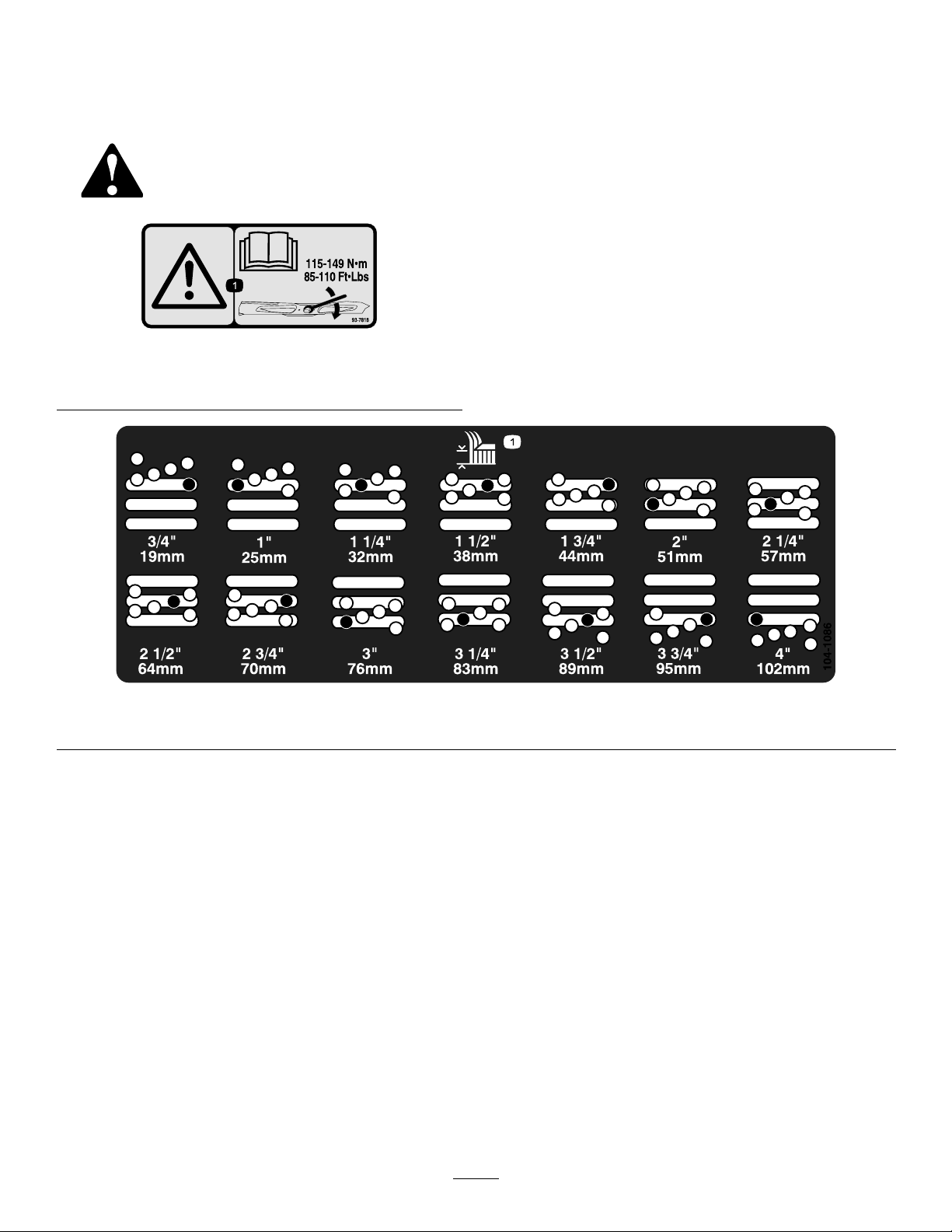
Safetydecalsandinstructionsareeasilyvisibletotheoperatorandarelocatednearanyareaof
potentialdanger.Replaceanydecalthatisdamagedorlost.
93-7818
1.Warning—readtheOperator’sManualforinstructionson
torquingthebladebolt/nutto115-149N-m(85-110ft-lb).
1.Heightofcut
104-1086
3
Page 4
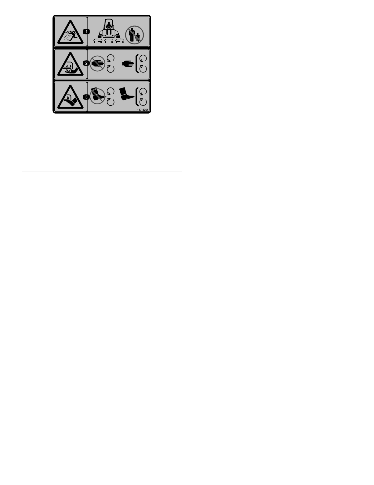
117-4764
1.Thrownobjecthazard—keepbystandersasafedistance
fromthemachine.
2.Cuttinghazardofhand,mowerblade—stayawayfrom
movingparts,keepallguardsandshieldsinplace.
3.Cuttinghazardoffoot,mowerblade—stayawayfrom
movingparts,keepallguardsandshieldsinplace.
4
Page 5
Setup
G011346
1
2
3
MediaandAdditionalParts
Description
Operator’sManual
PartsCatalog
AdjustingtheHeight-of-Cut
Important:Thiscuttingdeckoftencuts
approximately1/4inch(6mm)lowerthanareel
cuttingunitwiththesamebenchsetting.Itmaybe
necessarytohavetheserotarycuttingdeck’sbench
set1/4inch(6mm)abovethatofreelscuttingin
thesamearea.
Important:Accesstotherearcuttingunitsis
greatlyimprovedbyremovingthecuttingunitfrom
thetractor.Refertoremovingthecuttingdeckfrom
thetractionunitintheMaintenanceSection.
1.Lowerthecuttingdecktotheground,stopthe
engine,andremovethekeyfromignitionswitch.
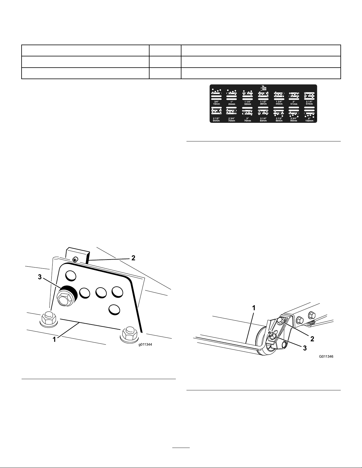
2.Loosentheboltsecuringeachheight-of-cutbracket
totheheight-of-cutplate(frontandeachside)
(Figure2).
Qty.
1
1Usetolookupparts.
Readbeforeoperating.
6.Positionthetappedplateinlinewiththespacer.
7.Installtheboltngertight.
8.Repeatsteps4–7foreachsideadjustment.
9.Tightenallthreeboltsto30ft-lb(41N-m).Always
Use
Figure3
tightenthefrontboltrst.
Note:Adjustmentsofmorethan1-1/2inches
(3.8cm)mayrequiretemporaryassemblytoan
intermediateheighttopreventbinding(e.g.changing
from1.25to2.75inch(3.1to7cm)height-of-cut).
3.Beginningwithfrontadjustment,removethebolt.
Figure2
1.Heightofcutbracket3.Spacer
2.Heightofcutplate
4.Whilesupportingthechamber,removethespacer
(Figure2).
5.Movethechambertothedesiredheight-of-cutand
installaspacerintothedesignatedheight-of-cuthole
andslot(Figure3).
AdjustingtheRollerScraper
(Optional)
Theoptionalrearrollerscraperisdesignedtoworkbest
whenthereisanevengapof0.020–0.040inch(0.5to1
mm)betweenthescraperandroller.
1.Loosenthegreasettingandmountingscrew
(Figure4).
Figure4
1.Rollerspacer
2.Mountingscrew
2.Slidethescraperupordownuntilagapof0.020to
0.040inch(0.5to1mm)isachievedbetweenthe
rodandtheroller.
3.Securethegreasettingandscrewto30ft-lb(41
N-m)inanalternatingsequence.
3.Greasetting
5
Page 6

InstallingtheMulchingBafe
G011347
1
(Optional)
1.Thoroughlycleandebrisfromthemountingholes
ontherearwallandleftsidewallofthechamber.
2.Installthemulchingbafeintherearopeningand
secureitwith5angeheadbolts(Figure5).
ProductOverview
Specications
Note:Specicationsanddesignaresubjecttochange
withoutnotice.
DimensionsandWeights(approx.)
Figure5
1.Mulchingbafe
3.Verifythatmulchingbafedoesnotinterferewith
thetipofthebladeanddoesnotprotrudeinsidethe
surfaceoftherearchamberwall.
Donotusethehighliftbladewiththemulching
bafe.Thebladecouldbreak,resultingin
personalinjuryordeath.
Length
Width
Height
Netweight
31.8inches(80.8cm)
28.4inches(72.1cm)
8.5inches(21.6cm)tocarriermount10.5inches
(26.7cm)at3/4inchheightofcutwithdrivemotor
13.7inches(34.8cm)at4inchheightofcutwith
drivemotor
140pounds(63.5kg)
Attachments/Accessories
AselectionofToroapprovedattachmentsand
accessoriesareavailableforusewiththemachineto
enhanceandexpanditscapabilities.Contactyour
AuthorizedServiceDealerorDistributororgoto
www.Toro.comforalistofallapprovedattachments
andaccessories.
6
Page 7

Operation
Note:Determinetheleftandrightsidesofthe
machinefromthenormaloperatingposition.
SelectingaBlade
StandardCombinationSail
Thisbladewasdesignedtoprovideexcellentliftand
dispersioninalmostanycondition.Ifmoreorlesslift
anddischargevelocityisrequired,consideradifferent
blade.
Attributes:Excellentliftanddispersioninmost
conditions.
AngledSail
Thebladegenerallyperformsbestinlowerheightsof
cut—3/4to2–1/2inch(1.9to6.4cm).
Attributes:
AtomicBlade
Thisbladewasdesignedtoprovideexcellentleaf
mulching.
Attributes:Excellentleafmulching
OperatingTips
MowwhentheGrassisDry
Moweitherinthelatemorningtoavoidthedew,which
causesgrassclumping,orinlateafternoontoavoidthe
damagethatcanbecausedbydirectsunlightonthe
sensitive,freshlymowedgrass.
SelecttheProperHeight-of-CutSetting
toSuitConditions
Removeapproximatelyoneinchornomorethan1/3
ofthegrassbladewhencutting.Inexceptionallylush
anddensegrassyoumayhavetoraisetheheight–of–cut
setting.
•Dischargeremainsmoreevenatlowerheightsof
cut.
•Dischargehaslesstendencytothrowleftandthusa
cleanerlookaroundbunkersandfairways.
•Lowerpowerrequirementatlowerheightsand
denseturf.
HighLiftParallelSail
Thebladegenerallyperformsbetterinthehigher
heightsofcut—2to4inch(7to10cm).
Attributes:
•Moreliftandhigherdischargevelocity .
•Sparseorlimpturfispickedupsignicantlyat
higherheightsofcut.
•Wetorstickyclippingsaredischargedmore
efcientlyreducingcongestioninthedeck.
•Requiresmorehorsepowertorun.
•Tendstodischargefurtherleftandcantendto
windrowatlowerheightsofcut.
AlwaysStartMowingwithSharp
Blades
Asharpbladecutscleanlyandwithouttearingor
shreddingthegrassbladeslikeadullblade.Tearingand
shreddingcausesthegrasstoturnbrownattheedges
whichimpairsgrowthandincreasessusceptibilityto
diseases.Makesurebladeisingoodconditionand
afullsailispresent.
CheckConditionofDeck
Makesurethatthecuttingchambersareingood
condition.Straightenanybendsinthechamber
componentstoensurethecorrectbladetip/chamber
clearance.
AfterOperating
Toensureoptimumperformance,cleantheunderside
ofmowerhousing.Ifyouallowresiduetobuildupin
mowerhousing,cuttingperformancewilldecrease.
Donotusethehighliftbladewiththemulching
bafe.Thebladecouldbreak,resultingin
personalinjuryordeath.
7
Page 8

ChoosingAccessories
AngleSailBladeHighLiftParallel
GrassCutting:0.75to
1.75inch(1.9to4.4cm)
Height-of-Cut
GrassCutting:2.00to
2.50inch(5to6.4cm)
Height-of-Cut
GrassCutting:2.75to
4.00inch(7to10cm)
Height-of-Cut
LeafMulchingRecommendedforuse
ProsEvendischargeat
ConsDoesnotliftthegrass
Recommendedinmost
applications
Recommendedforthick
orlushturf
Mayworkwellinlushturf
withthemulchingbafe
lowerheightofcut
Cleanerlookaround
bunkersandfairways
Lowerpower
requirements
wellinhighheight
ofcutapplications
Wetorstickygrass
hasatendencytobuild
upinthechamber,
leadingtopoorquality
ofcutandhigherpower
requirement
OptionalEquipmentConguration
SailBlade
Donotusewiththe
mulchingbafe
Mayworkwellinlightor
sparseturf
Recommendedforlight
orsparseturf
Recommendedinmost
applications
NotAllowedUsewithcombinationsail
Moreliftandhigher
dischargevelocity
Sparseorlimpturf
ispickedupat
highheightofcut
Wetorstickyclippings
aredischargedefciently
Requiresmorepowerto
runinsomeapplications
Tendstowindrow
atlowerheightof
cutinlushgrass
Donotusewiththe
mulchingbafe
MulchingBafeRollerScraper
Hasbeenshownto
improvedispersionand
aftercutperformance
onnortherngrassesthat
arecutatleastthree
timesperweekandless
than1/3ofthegrass
bladeisremoved.
Donotusewiththe
highliftparallelsail
blade
oranglesailbladeonly
Mayimprovedispersion
andappearancein
certaingrasscutting
applicationsVerygood
forleafmulching
Grasswillbuildupinthe
chamberifattemptingto
removetoomuchgrass
withbafeinplace
Canbeusedanytime
thatrollersbuildup
withgrassorlargeat
grassclumpsofgrass
areseen.Thescrapers
mayactuallyincrease
clumpingincertain
applications.
Reducesrollerbuildupin
certainapplications
8
Page 9

Maintenance
g011618
G011349
Note:Determinetheleftandrightsidesofthemachinefromthenormaloperatingposition.
RecommendedMaintenanceSchedule(s)
MaintenanceService
Interval
Beforeeachuseordaily
Every50hours
Ifyouleavethekeyintheignitionswitch,someonecouldaccidentlystarttheengineandseriously
injureyouorotherbystanders.
Removethekeyfromtheignitionanddisconnectthewirefromthesparkplugbeforeyoudoany
maintenance.Setthewireasidesothatitdoesnotaccidentallycontactthesparkplug .
GreasingtheBearings
ServiceInterval:Every50hours
Eachcuttingdeckhastwogreasettingsperspindle.
Eitherttingcanbeused,whicheverismoreaccessible.
Ifthemachineisoperatedundernormalconditions,
lubricatebladespindlebearings(Figure6)withNo.2
generalpurposelithiumbasegreaseormolybdenum
basegrease,afterevery50hoursofoperation.Pump
greaseintothettinguntilasmallamountappearsat
bottomofthespindlehousing(underthedeck).
MaintenanceProcedure
•Checkthebladestoppingtime.
•Greasethebearings
generalpurposelithiumbasegreaseormolybdenum
basegrease,afterevery50hoursofoperation.
Figure7
Figure6
Eachcuttingdeckhastwogreasettingsperrearroller.
Ifthemachineisoperatedundernormalconditions,
lubricaterearrollerbearings(Figure7)withNo.2
Important:Makesurethegreasegrooveineach
rollermountalignswiththegreaseholeineachend
oftherollershaft.T ohelpalignthegrooveandhole,
thereisalsoanatononeendoftherollershaft.
SeparatingtheCuttingDecks
fromtheTractionUnit
1.Positionthemachineonalevelsurface,lowerthe
cuttingdeckstotheoor,shuttheengineoff,and
engagetheparkingbrake.
2.Disconnectandremovethehydraulicmotorfrom
thedeck(Figure8).Coverthetopofthespindleto
preventcontamination.
Note:Therearcuttingdeckmotorsarepositioned
differentthanthefrontmotors.Notethemotor
orientationforcorrectreassembly.
9
Page 10

g011619
1
Figure8
1.Motormountingscrews
3.Removethelynchpinsecuringthedeckcarrierframe
totheliftarmpivotpin(Figure9).
Figure10
1.Carrierframe4.Liftarmpivotpin
2.Flagpin5.Lynchpin
3.Boltandnut
3.Movecuttingdeckintopositioninfrontoftraction
unit.
4.Slidedeckcarrierframeontoliftarmpivotpin.
Securewithlynchpin(Figure9).
5.Installthehydraulicmotortothedeck(Figure8).
MakesurethattheO-ringisinpositionandnot
damaged.
6.Greasethespindle.
MountingtheFrontCutting
Figure9
1.Liftarmpivotpin
2.Lynchpin
4.Rollthecuttingdeckawayfromthetractionunit.
MountingtheRearCutting
DeckstotheTractionUnit
1.Positionmachineonalevelsurfaceandshutengine
off.
2.Pivotthecarrierframeforwardandsecureittothe
deckbracketwiththeagpin,boltandnut.Position
asshowninFigure10.
DeckstotheTractionUnit
1.Positionmachineonalevelsurfaceandshutengine
off.
2.Pivotthecarrierframerearwardandsecureittothe
deckbracketwiththeagpin,boltandnut.Position
asshowninFigure11.
10
Page 11

Figure11
G011353
6:00
12:00
9:00
3:00
1.Carrierframe4.Liftarmpivotpin
2.Flagpin5.Lynchpin
3.Boltandnut
•
3.Movecuttingdeckintopositioninfrontoftraction
unit.
4.Slidedeckcarrierframeontoliftarmpivotpin.
Securewithlynchpin(Figure9).
5.Installthehydraulicmotortothedeck(Figure8).
MakesurethattheO-ringisinpositionandnot
damaged.
6.Greasethespindle.
ServicingtheBladePlane
Therotarydeckcomesfromthefactorypresetat2.00
inch(5cm)height-of-cutandbladerakeof0.310inch
(7.9mm).Theleft-handandright-handheightsarealso
presettowithin±0.030inch(0.7mm)oftheother.
Thecuttingdeckisdesignedtowithstandbladeimpacts
withoutdeformationofthechamber.Ifasolidobject
isstruck,inspectthebladefordamageandtheblade
planeforaccuracy .
Figure12
5.Rotatethemarkedendofthebladetothe3and
9o’clockpositions(Figure12)andmeasurethe
heights.
6.Comparethe12o’clockmeasuredheighttothe
height-of-cutsetting.Itshouldbewithin0.030inch
(0.7mm).The3and9o’clockheightsshouldbe
0.150±.090inch(3.8±2.2mm)higherthanthe12
o’clocksettingandwithin0.090inch(2.2mm)of
eachother.
Ifanyofthesemeasurementsarenotwithin
specication,proceedtoAdjustingtheBladePlane.
AdjustingtheBladePlane
Startwiththefrontadjustment(changeonebracketata
time).
1.Removetheheight-of-cutbracket,(front,left,or
right)fromthedeckframe(Figure13).
2.Adjust0.060inch(1.5mm)shimsand/or0.030inch
(0.7mm)shimbetweenthedeckframeandbracket
toachievethedesiredheightsetting(Figure13).
InspectingtheBladePlane
1.Removethehydraulicmotorfromthecuttingdeck
andremovethecuttingdeckfromthetractor.
2.Useahoist(orminimumoftwopeople)andplace
thecuttingdeckonaattable.
3.Markoneendofthebladewithapaintpenor
4.Positionthecuttingedgeofthemarkedendofthe
marker.Usethisendofthebladetocheckallheights.
bladeat12o’clock(straightaheadinthedirectionof
mowing)(Figure12)andmeasureheightfromtable
tocuttingedgeofblade.
11
Page 12

Figure13
G011355
1
2
1.Heightofcutbracket2.Shims
3.Installtheheight-of-cutbrackettothedeckframe
withtheremainingshimsassembledbelowthe
height-of-cutbracket.
4.Securethebracketwiththeboltandnut.
Figure14
1.Bladebolt2.Anti-scalpcup
3.Installtheblade,sailfacingtowardthecuttingdeck,
withtheanti-scalpcupandbladebolt(Figure14).
Tightenbladeboltto85–110ft-lb(115–149N-m).
5.Verifythe12o’clockheightandadjustifneeded.
6.Determineifonlyoneorboth(right-handand
left-hand)height-of-cutbracketsneedtobeadjusted.
Ifthe3or9o’clocksideis0.150±0.090inch
(3.8±2.2mm)higherthanthenewfrontheightthen
noadjustmentisneededforthatside.Adjustthe
othersidetowithin±0.090inch(2.2mm)ofthe
correctside.
7.Adjusttherightand/orleftheight-of-cutbracketsby
repeatingsteps1through3.
8.Securethecarriageboltsandangenuts.
9.Again,verifythe12,3,and9o’clockheights.
RemovingtheCutterBlade
Theblademustbereplacedifasolidobjectishit,the
bladeisoutofbalance,orifthebladeisbent.Always
usegenuineTororeplacementbladestobesureofsafety
andoptimumperformance.Neverusereplacement
bladesmadebyothermanufacturersbecausetheycould
bedangerous.
1.Raisethecuttingdecktothehighestposition,
shuttheengineoff,andengagetheparkingbrake.
Blockthecuttingdecktopreventitfromfalling
accidentally.
Awornordamagedbladecanbreak,anda
pieceofthebladecouldbethrownintothe
operator’sorbystander’sarea,resultingin
seriouspersonalinjuryordeath.
•Inspectthebladeperiodicallyforwearor
damage.
•Neverweldabrokenorcrackedblade.
•Alwaysreplaceawornordamagedblade.
InspectingandSharpeningthe
Blade
1.Raisethecuttingdecktothehighestposition,
shuttheengineoff,andengagetheparkingbrake.
Blockthecuttingdecktopreventitfromfalling
accidentally.
2.Examinethecuttingendsofthebladecarefully ,
especiallywheretheatandcurvedpartsofthe
blademeet(Figure15).Sincesandandabrasive
materialcanwearawaythemetalthatconnects
theatandcurvedpartsoftheblade,checkthe
bladebeforeusingthemachine.Ifwearisnoticed
(Figure15),replacetheblade;refertoRemovingthe
CutterBlade.
2.Grasptheendofthebladeusingaragorthickly
paddedglove.Removethebladebolt,anti-scalpcup,
andbladefromthespindleshaft(Figure14).
12
Page 13

theheel,thebladeisbentorwarpedandmustbe
replaced.
Ifthebladeisallowedtowear,aslotwillform
betweenthesailandatpartoftheblade
(Figure15).Eventuallyapieceoftheblade
maybreakoffandbethrownfromunderthe
housing,possiblyresultinginseriousinjuryto
yourselforbystanders.
•Inspectthebladeperiodicallyforwearor
damage.
•Alwaysreplaceawornordamagedblade.
Figure15
1.Cuttingedge3.Wear/slot/crack
2.Sail
5.Installtheblade,sailfacingtowardcuttingdeck,with
theanti-scalpcupandbladebolt.Tightentheblade
boltto85–110ft-lb(115–149N-m).
CheckingtheBladeStopping
Time
ServiceInterval:Beforeeachuseordaily
Thebladesofthecuttingdeckshouldcometoa
completestopinapproximately5secondsafteryoushut
downthecuttingdeckengagementswitch.
Note:Makesurethedecksareloweredontoaclean
sectionofturforhardsurfacetoavoidthrowndustand
debris.
Toverifythisstoppingtime,haveasecondpersonstand
backfromthedeckatleast20feet(6m)andwatchthe
bladesononeofthecuttingdecks.Havetheoperator
shutthecuttingdecksdownandrecordthetimeit
takesforthebladestocometoacompletestop.Ifthis
timeisgreaterthan7seconds,thebrakingvalveneeds
adjustment.CallyourToroDistributorforassistance
inmakingthisadjustment.
3.Inspectthecuttingedgesofallblades.Sharpenthe
cuttingedgesiftheyaredullornicked.Sharpenonly
thetopofthecuttingedgeandmaintaintheoriginal
cuttingangletomakesureofsharpness(Figure16).
Thebladewillremainbalancedifthesameamount
ofmetalisremovedfrombothcuttingedges.
Figure16
1.Sharpenatthisangleonly
4.Tocheckthebladeforbeingstraightandparallel,
laythebladeonalevelsurfaceandcheckitsends.
Theendsoftheblademustbeslightlylowerthan
thecenter,andthecuttingedgemustbelowerthan
theheeloftheblade.Thisbladewillproducegood
qualityofcutandrequireminimalpowerfromthe
engine.Bycontrastabladethatishigherattheends
thanthecenter,orifcuttingedgeishigherthan
ServicingtheFrontRoller
Inspectthefrontrollerforwear,excesswobble,or
binding.Serviceorreplacetherollerorcomponentsif
anyoftheseconditionsexist.
DisassemblingtheFrontRoller
1.Removetherollermountingbolt(Figure17).
2.Removetherollerassemblyandrollerposition
spacerfromthedeckframe(Figure17).Notethe
positionoftherollerpositionspacerforreassembly.
3.Insertapunchthroughtheendoftherollerhousing
anddrivetheoppositebearingoutbyalternating
tapstotheoppositesideofinnerbearingrace.There
shouldbea0.060inch(1.5mm)lipofinnerrace
exposed.
13
Page 14

G011610
1
2
3
4
5
Figure17
1.Frontroller4.Bearingspacer
2.Mountingbolt5.Rollerpositionspacer
3.Bearing
4.Pushthesecondbearingoutinpress.
5.Inspecttherollerhousing,bearings,andbearing
spacerfordamage(Figure17).Replacedamaged
componentsandassemble.
Storage
Ifthecuttingdeckisseparatedfromthetractionunitfor
anylengthoftime,installaspindlepluginthetopofthe
spindletoprotectthespindlefromdustandwater.
AssemblingtheFrontRoller
1.Presstherstbearingintotherollerhousing
(Figure17).Pressontheouterraceonlyorequally
ontheinnerandouterrace.
2.Insertthespacer(Figure17).
3.Pressthesecondbearingintotherollerhousing
(Figure17)pressingequallyontheinnerandouter
raceuntiltheinnerracecomesincontactwiththe
spacer.
4.Looselyinstalltherollerassemblyandrollerposition
spacerintothedeckframewiththemountingbolt.
Note:Insomegrassconditions,thequalityofcut
maybeimprovedbymovingtherollerposition
spacertotheinsideoftheroller(Figure17).
Important:Securingtherollerassemblywith
agaplargerthan0.060inch(1.5mm)creates
asideloadonthebearingandcanleadto
prematurebearingfailure.
5.Verifythatthereisnomorethana0.060inch
gapbetweenrollerassemblyandtherollermount
bracketsofthedeckframe.Ifthereisagapover
0.060inch,installenough5/8inchdiameterwashers
totakeuptheslop.
6.Securethemountingboltto80ft-lb(108N-m).
14
Page 15

Notes:
15
Page 16

Toro General Commercial Products Warranty
A Two-Year Limited Warranty
Conditions and Products Covered
The Toro Company and its affi liate, Toro Warranty Company, pursuant
to an agreement between them, jointly warrant your Toro Commercial
Product (“Product”) to be free from defects in materials or workmanship for two years or 1500 operational hours*, whichever occurs
fi rst. This warranty is applicable to all products with the exception of
Aerators (refer to separate warranty statements for these products).
Where a warrantable condition exists, we will repair the Product at no
cost to you including diagnosis, labor, parts, and transportation. This
warranty begins on the date the Product is delivered to the original
retail purchaser.
* Product equipped with hour meter
Instructions for Obtaining Warranty Service
You are responsible for notifying the Commercial Products Distributor
or Authorized Commercial Products Dealer from whom you purchased the Product as soon as you believe a warrantable condition
exists. If you need help locating a Commercial Products Distributor or
Authorized Dealer, or if you have questions regarding your warranty
rights or responsibilities, you may contact us at:
Toro Commercial Products Service Department
Toro Warranty Company
8111 Lyndale Avenue South
Bloomington, MN 55420-1196
952-888-8801 or 800-952-2740
E-mail: [email protected]
Owner Responsibilities
As the Product owner, you are responsible for required maintenance
and adjustments stated in your Operator’s Manual. Failure to perform
required maintenance and adjustments can be grounds for disallowing a warranty claim.
Items and Conditions Not Covered
Not all product failures or malfunctions that occur during the warranty
period are defects in materials or workmanship. This warranty does
not cover the following:
Product failures which result from the use of non-Toro replace-
•
ment parts, or from installation and use of add-on, or modifi ed
non-Toro branded accessories and products. A separate waranty
may be provided by the manufacturer of these items.
Product failures which result from failure to perform recomended
•
maintenance and/or adjustments. Failure to properly maintain
your Toro product per the Recommended Maintenance listed in
the Operator’s Manual can result in claims for warranty being
denied.
Product failures which result from operating the Product in an
•
abusive, negligent or reckless manner.
Parts subject to consumption through use unless found to be
•
defective. Examples of parts which are consumed, or used up,
during normal Product operation include, but are not limited to,
brake pads and linings, clutch linings, blades, reels, rollers and
bearings (sealed or greasable), bed knives, aerator crankshaft
and stomper arm bearings, tines, spark plugs, castor wheels and
bearings, tires, fi lters, belts, and certain sprayer components
such as diaphragms, nozzles, and check valves, etc.
Failures caused by outside infl uence. Conditions considered to be
•
outside infl uence include, but are not limited to, weather, storage
practices, contamination, use of unapproved coolants, lubricants,
additives, fertilizers, water, or chemicals, etc.
•
Normal noise, vibration, wear and tear, and deterioration.
•
Normal “wear and tear” includes, but is not limited to, damage to
seats due to wear or abrasion, worn painted surfaces, scratched
decals or windows, etc.
Parts
Parts scheduled for replacement as required maintenance are warranted for the period of time up to the scheduled replacement time
for that part. Parts replaced under this warranty are covered for the
duration of the original product warranty and become the property of
Toro. Toro will make the fi nal decision whether to repair any existing
part or assembly or replace it. Toro may use remanufactured parts for
warranty repairs.
Note Regarding Deep Cycle Battery Warranty:
Deep cycle batteries have a specifi ed total number of kilowatt-hours
they can deliver during their lifetime. Operating, recharging, and aintenance techniques can extend or reduce total battery life. As the batteries in this product are consumed, the amount of useful work between
charging intervals will slowly decrease until the battery is completely
worn out. Replacement of worn out batteries, due to normal consumption, is the responsibility of the product owner. Battery replacement
may be required during the normal product warranty period at owner’s
expense.
Maintenance is at Owner’s Expense
Engine tune-up, lubrication cleaning and polishing, replacement of
fi lters, coolant, and completing recommended maintenance are some
of the normal services Toro products require that are at the owner’s
expense.
General Conditions
Repair by an Authorized Toro Distributor or Dealer is your sole remedy
under this warranty.
Neither The Toro Company nor Toro Warranty Company is liable
for indirect, incidental or consequential damages in connetion
with the use of the Toro Products covered by this warranty,
including any cost or expense of providing substitute equipment
or service during reasonable periods of malfunction or non-use
pending completion of repairs under this warranty. Except for the
Emissions warranty referenced below, if applicable, there is no
other express warranty. All implied warranties of merchantability
and fi tness for use are limited to the duration of this express war-
ranty.
Some states do not allow exclusions of incidental or consequential
damages, or limitations on how long an implied warranty lasts, so the
above exclusions and limitations may not apply to you. This warranty
gives you specifi c legal rights, and you may also have other rights
which vary from state to state.
Note regarding engine warranty:
The Emissions Control System on your Product may be covered by a
separate warranty meeting requirements established by the U.S. Environmental Protection Agency (EPA) and/or the California Air Resources Board (CARB). The hour limitations set forth above do not apply to
the Emissions Control System Warranty. Refer to the Engine Emission
Control Warranty Statement supplied with your product or contained in
the engine manufacturer’s documentation for details.
Countries Other than the United States or Canada
Customers who have purchased Toro products exported from the United States or Canada should contact their Toro Distributor (Dealer) to obtain
guarantee policies for your country, province, or state. If for any reason you are dissatisfi ed with your Distributor’s service or have diffi culty ob-
taining guarantee information, contact the Toro importer.
Part No. 374-0031 Rev. E
 Loading...