

Page 1

FormNo.3385-788RevA
Groundsmaster
®
3500-Dand
3505-DRotaryMowers
ModelNo.30807—SerialNo.314000001andUp
ModelNo.30839—SerialNo.314000001andUp
ModelNo.30843—SerialNo.314000001andUp
ModelNo.30849—SerialNo.314000001andUp
Registeratwww.T oro.com.
OriginalInstructions(EN)
*3385-788*A
Page 2
ThisproductcomplieswithallrelevantEuropeandirectives,
fordetailspleaseseetheseparateproductspecicDeclaration
ofConformity(DOC)sheet.
WARNING
CALIFORNIA
Proposition65Warning
Thisproductcontainsachemicalorchemicals
knowntotheStateofCaliforniatocausecancer,
birthdefects,orreproductiveharm.
Dieselengineexhaustandsomeofits
constituentsareknowntotheStateof
Californiatocausecancer,birthdefects,
andotherreproductiveharm.
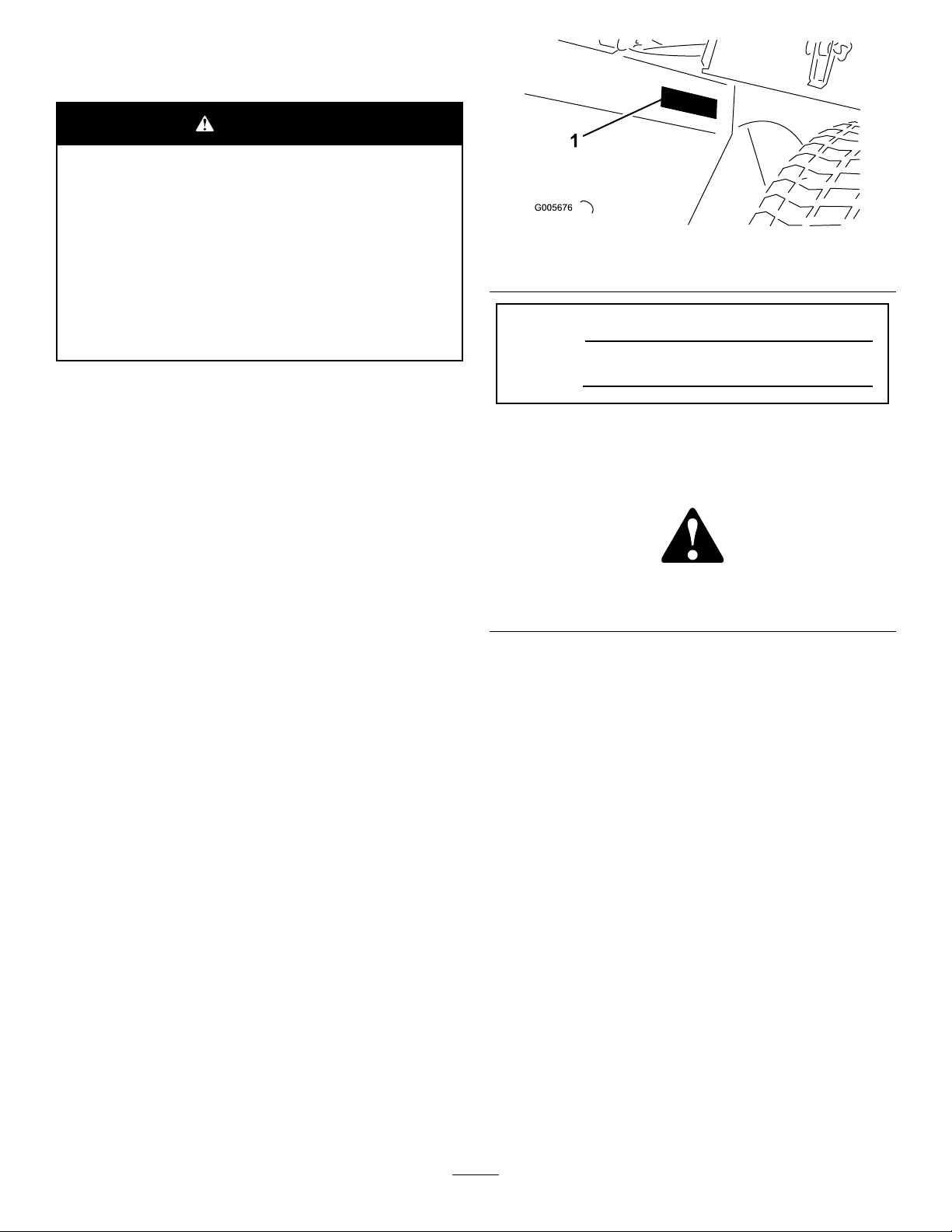
Figure1
1.Modelandserialnumberlocation
ModelNo.
Important:Thisengineisnotequippedwithaspark
arrestermufer.ItisaviolationofCaliforniaPublic
ResourceCodeSection4442touseoroperatetheengine
onanyforest-covered,brush-covered,orgrass-covered
land.Otherstatesorfederalareasmayhavesimilarlaws.
Introduction
Thismachineisaride-on,rotary-bladelawnmowerintended
tobeusedbyprofessional,hiredoperatorsincommercial
applications.Itisprimarilydesignedforcuttinggrasson
well-maintainedlawnsinparks,golfcourses,sportselds,
andoncommercialgrounds.Itisnotdesignedforcutting
brush,mowinggrassandothergrowthalongsidehighways,
orforagriculturaluses.
Readthisinformationcarefullytolearnhowtooperateand
maintainyourproductproperlyandtoavoidinjuryand
productdamage.Youareresponsibleforoperatingthe
productproperlyandsafely.
YoumaycontactTorodirectlyatwww .Toro.comforproduct
andaccessoryinformation,helpndingadealer,ortoregister
yourproduct.
SerialNo.
Thismanualidentiespotentialhazardsandhassafety
messagesidentiedbythesafetyalertsymbol(Figure2),
whichsignalsahazardthatmaycauseseriousinjuryordeath
ifyoudonotfollowtherecommendedprecautions.
Figure2
1.Safetyalertsymbol
Thismanualuses2otherwordstohighlightinformation.
Importantcallsattentiontospecialmechanicalinformation
andNoteemphasizesgeneralinformationworthyofspecial
attention.
Wheneveryouneedservice,genuineT oroparts,oradditional
information,contactanAuthorizedServiceDealerorToro
CustomerServiceandhavethemodelandserialnumbers
ofyourproductready.Figure1identiesthelocationofthe
modelandserialnumbersontheproduct.Writethenumbers
inthespaceprovided.
©2014—TheToro®Company
8111LyndaleAvenueSouth
Bloomington,MN55420
Contactusatwww.Toro.com.
2
PrintedintheUSA.
AllRightsReserved
Page 3

Contents
Safety...........................................................................4
SafeOperatingPractices...........................................4
ToroMowerSafety..................................................6
SoundPowerLevel..................................................7
SoundPressureLevel...............................................7
VibrationLevel......................................................7
SafetyandInstructionalDecals.................................8
Setup...........................................................................15
1Activating,Charging,andConnectingthe
Battery..............................................................15
2CheckingtheAngleIndicator(Models30839,
30843and30807only).........................................17
3InstallingtheCEDecals........................................17
4InstallingtheHoodLatch(CEOnly).......................17
5InstallingtheExhaustGuard(CEOnly)..................18
6AdjustingtheLiftArms........................................19
7RearBallast.........................................................20
8AdjustingtheCarrierFrame..................................20
9AdjustingtheHeight-of-Cut..................................21
10AdjustingtheRollerScraper(Optional).................21
11InstallingtheMulchingBafe(Optional)...............22
ProductOverview.........................................................23
Controls...............................................................23
Specications........................................................25
Attachments/Accessories........................................25
Operation....................................................................25
CheckingtheEngineOilLevel.................................25
FillingtheFuelTank...............................................26
CheckingtheCoolingSystem...................................26
CheckingtheHydraulicSystem................................27
CheckingtheTirePressure......................................28
TorquingtheWheelNuts........................................28
StartingandStoppingtheEngine..............................28
BleedingtheFuelSystem.........................................29
CheckingtheInterlockSystem.................................29
TowingtheTractionUnit.........................................30
StandardControlModule(SCM)..............................30
SelectingaBlade.....................................................32
ChoosingAccessories.............................................33
OperatingTips......................................................34
Maintenance.................................................................37
RecommendedMaintenanceSchedule(s)......................37
DailyMaintenanceChecklist....................................38
ServiceIntervalChart.............................................40
PremaintenanceProcedures........................................40
RemovingtheHood...............................................40
UsingtheCuttingDeckServiceLatch.......................40
Lubrication...............................................................42
GreasingtheBearingsAndBushings.........................42
EngineMaintenance..................................................44
ServicingtheAirCleaner.........................................44
ChangingtheEngineOilandFilter...........................45
FuelSystemMaintenance...........................................46
ServicingtheFuelTank...........................................46
InspectingtheFuelLinesandConnections.................46
DrainingtheWaterSeparator...................................46
ChangingtheFuelFilterCanister..............................46
BleedingAirfromtheInjectors................................46
ElectricalSystemMaintenance....................................47
CaringfortheBattery..............................................47
Fuses....................................................................47
DriveSystemMaintenance.........................................48
AdjustingtheTractionDriveforNeutral....................48
CoolingSystemMaintenance......................................48
CleaningtheEngineCoolingSystem.........................48
BrakeMaintenance....................................................49
AdjustingtheParkingBrake.....................................49
BeltMaintenance......................................................49
ServicingtheEngineBelts.......................................49
ControlsSystemMaintenance.....................................50
AdjustingtheThrottle.............................................50
HydraulicSystemMaintenance....................................51
ChangingtheHydraulicFilter...................................51
ChangingtheHydraulicFluid...................................51
CheckingtheHydraulicLinesandHoses....................52
CuttingDeckMaintenance..........................................52
SeparatingtheCuttingDecksfromtheTraction
Unit..................................................................52
MountingtheCuttingDeckstotheTraction
Unit..................................................................53
ServicingtheBladePlane.........................................53
ServicingtheCutterBlade.......................................54
ServicingtheFrontRoller........................................55
Storage........................................................................56
StoringtheBattery..................................................56
PreparationforSeasonalStorage..............................56
3
Page 4

Safety
ThismachinemeetsorexceedsISOstandard5395:2013
(whenappropriatedecalsapplied),andANSIB71.4-2012
specicationsineffectatthetimeofproductionwhen
equippedwithrequiredweightaslistedinRearBallast
section.
Improperuseormaintenancebytheoperatoror
ownercanresultininjury.Toreducethepotential
forinjury,complywiththesesafetyinstructionsand
alwayspayattentiontothesafetyalertsymbol,which
meansCaution,Warning,orDanger—personalsafety
instruction.Failuretocomplywiththeinstructionmay
resultinpersonalinjuryordeath.
SafeOperatingPractices
ThefollowinginstructionsareadaptedfromtheISOstandard
5395:2013,andANSIB71.4-2012.
Training
•ReadtheOperator’sManualandothertrainingmaterial
carefully.Befamiliarwiththecontrols,safetysigns,and
theproperuseoftheequipment.
•Iftheoperatorormechaniccannotreadthelanguage
ofthismanual,itistheowner’sresponsibilitytoexplain
thismaterialtothem.
•Neverallowchildrenorpeopleunfamiliarwiththese
instructionstouseorservicethemower.Local
regulationsmayrestricttheageoftheoperator.
•Nevermowwhilepeople,especiallychildren,orpetsare
nearby.
•Keepinmindthattheoperatororuserisresponsiblefor
accidentsorhazardsoccurringtootherpeopleortheir
property.
•Donotcarrypassengers.
•Alldriversandmechanicsshouldseekandobtain
professionalandpracticalinstruction.Theowneris
responsiblefortrainingtheusers.Suchinstructionshould
emphasizethefollowing:
–Theneedforcareandconcentrationwhenworking
withride-onmachines
–Controlofaride-onmachineslidingonaslopewill
notberegainedbytheapplicationofthebrake.The
mainreasonsforlossofcontrolareasfollows:
◊Insufcientwheelgrip
◊Beingdriventoofast
◊Inadequatebraking
◊Thetypeofmachineisunsuitableforthetask
◊Lackofawarenessoftheeffectofground
conditions,especiallyslopes
◊Incorrecthitchingandloaddistribution
Preparation
•Whilemowing,alwayswearsubstantialfootwear,long
trousers,hardhat,safetyglasses,andhearingprotection.
Longhair,looseclothing,orjewelrymaygettangled
inmovingparts.Donotoperatetheequipmentwhen
barefootorwearingopensandals.
•Thoroughlyinspecttheareawheretheequipmentisto
beusedandremoveallobjectswhichmaybethrownby
themachine.
•Replacefaultysilencers/mufers.
•Beforeusing,alwaysvisuallyinspecttoseethatthe
blades,bladebolts,andcuttingassemblyarenotworn
ordamaged.Replacewornordamagedbladesandbolts
insetstopreservebalance.
•Onmulti-bladedmachines,takecareasrotatingoneblade
cancauseotherbladestorotate.
•Evaluatetheterraintodeterminewhataccessoriesand
attachmentsareneededtoproperlyandsafelyperform
thejob.Onlyuseaccessoriesandattachmentsapproved
bythemanufacturer.
•Checkthatoperator’spresencecontrols,safetyswitches
andshieldsareattachedandfunctioningproperly.Donot
operateunlesstheyarefunctioningproperly.
SafeHandlingofFuels
•Toavoidpersonalinjuryorpropertydamage,use
extremecareinhandlinggasoline.Gasolineisextremely
ammableandthevaporsareexplosive.
•Extinguishallcigarettes,cigars,pipes,andothersources
ofignition.
•Useonlyanapprovedfuelcontainer.
•Neverremovefuelcaporaddfuelwiththeengine
running.
•Allowenginetocoolbeforerefueling.
•Neverrefuelthemachineindoors.
•Neverstorethemachineorfuelcontainerwherethereis
anopename,spark,orpilotlightsuchasonawater
heateroronotherappliances.
•Neverllcontainersinsideavehicleoronatruckor
trailerbedwithaplasticliner.Alwaysplacecontainerson
thegroundawayfromyourvehiclebeforelling.
•Removeequipmentfromthetruckortrailerandrefuelit
ontheground.Ifthisisnotpossible,thenrefuelsuch
equipmentwithaportablecontainer,ratherthanfroma
fueldispensernozzle.
•Keepthenozzleincontactwiththerimofthefueltank
orcontaineropeningatalltimesuntilfuelingiscomplete.
Donotuseanozzlelockopendevice.
•Iffuelisspilledonclothing,changeclothingimmediately.
•Neveroverllfueltank.Replacefuelcapandtighten
securely.
4
Page 5

Operation
•Donotoperatetheengineinaconnedspacewhere
dangerouscarbonmonoxidefumescancollect.
•Mowonlyindaylightoringoodarticiallight.
•Beforeattemptingtostarttheengine,disengageallblade
attachmentclutches,shiftintoneutral,andengagethe
parkingbrake.Onlystarttheenginefromtheoperator’s
position.NeverremovetheROPSandalwayswearthe
seatbeltsduringoperation.
•Donotputhandsorfeetnearorunderrotatingparts.
Keepclearofthedischargeopeningatalltimes.
•Rememberthereisnosuchthingasasafeslope.Travel
ongrassslopesrequiresparticularcare.Dothefollowing
toguardagainstoverturning:
–Donotstoporstartsuddenlywhengoingupor
downhill.
–Keepmachinespeedslowonslopesandduringtight
turns.
–Stayalertforhumpsandhollowsandotherhidden
hazards.
–Nevermowacrossthefaceoftheslope,unlessthe
mowerisdesignedforthispurpose.
•Stayalertforholesintheterrainandotherhiddenhazards.
•Watchoutfortrafcwhencrossingornearroadways.
•Stopthebladesfromrotatingbeforecrossingsurfaces
otherthangrass.
•Whenusinganyattachments,neverdirectdischargeof
materialtowardbystandersnorallowanyonenearthe
machinewhileinoperation.
•Neveroperatethemachinewithdamagedguards,shields,
orwithoutsafetyprotectivedevicesinplace.Besureall
interlocksareattached,adjustedproperly ,andfunctioning
properly.
•Donotchangetheenginegovernorsettingsoroverspeed
theengine.Operatingtheengineatexcessivespeedmay
increasethehazardofpersonalinjury.
•Dothefollowingbeforeleavingtheoperator’ sposition:
–Stoponlevelground.
–Disengagethepowertake-offandlowerthe
attachments.
–Changeintoneutralandsettheparkingbrake.
–Stoptheengineandremovethekey.
•Disengagethedrivetoattachments,stoptheengine,and
removetheignitionkeyinthefollowingconditions:
–Beforemakingheightadjustments,unlessthe
adjustmentcanbemadefromtheoperator’sposition.
–Beforeclearingblockages
–Beforechecking,cleaning,orworkingonthemower
–Afterstrikingaforeignobjectorifanabnormal
vibrationoccurs(checkimmediately).Inspectthe
mowerfordamageandmakerepairsbeforerestarting
andoperatingtheequipment.Torqueallthespindle
pulleynutsto176to203N-m(130to150ft-lb).
•Disengagethedrivetoattachmentswhentransportingor
whennotmachineisnotinuse.
•Stoptheengineanddisengagethedrivetoattachments
beforethefollowing:
–Refueling
–Makingheightadjustment,unlesstheadjustmentcan
bemadefromtheoperator'sposition
•Reducethethrottlesettingbeforestoppingtheengine
and,iftheengineisprovidedwithafuelshut-offvalve,
turnthefueloffattheconclusionofmowing.
•Neverraisethecuttingunitwiththebladesrunning.
•Keephandsandfeetawayfromthecuttingunits.
•Lookbehindanddownbeforebackinguptobesureof
aclearpath.
•Slowdownandusecautionwhenmakingturnsand
crossingroadsandsidewalks.
•Donotoperatethemowerundertheinuenceofalcohol
ordrugs.
•Lightningcancausesevereinjuryordeath.Iflightning
isseenorthunderisheardinthearea,donotoperate
themachine;seekshelter.
•Usecarewhenloadingorunloadingthemachineintoa
trailerortruck.
•Theoperatorshallturnonashingwarninglights,if
provided,whenevertravelingonapublicroad,except
wheresuchuseisprohibitedbylaw .
MaintenanceandStorage
•Keepallnuts,boltsandscrewstighttobesurethe
equipmentisinsafeworkingcondition.
•Neverstoretheequipmentwithfuelinthetankinsidea
buildingwherefumesmayreachanopenameorspark.
•Allowtheenginetocoolbeforestoringinanyenclosure.
•Toreducetherehazard,keeptheengine,
silencer/mufer,batterycompartmentfuelstoragearea,
cuttingunitsanddrivesfreeofgrass,leaves,orexcessive
grease.Cleanupoilorfuelspillage.
•Replacewornordamagedpartsforsafety.
•Ifthefueltankhastobedrained,dothisoutdoors.
•Onmulti-bladedmachines,takecareasrotatingoneblade
cancauseotherbladestorotate.
•Whenmachineistobeparked,stored,orleftunattended,
lowerthecuttingunitsunlessapositivemechanicallock
isprovided.
•Disengagedrives,lowerthecuttingunits,setparking
brake,stopengineandremovekey .Waitforallmovement
tostopbeforeadjusting,cleaningorrepairing.
•Shutofffuelwhilestoringortransporting.Donotstore
fuelnearames.
5
Page 6

•Parkthemachineonlevelground.Neverallowuntrained
personneltoservicemachine.
•Usejackstandstosupportcomponentswhenrequired.
•Carefullyreleasepressurefromcomponentswithstored
energy.
•Disconnectbatterybeforemakinganyrepairs.Disconnect
thenegativeterminalrstandthepositivelast.Reconnect
positiverstandnegativelast.
•Usecarewhencheckingtheblades.Wrapthebladesor
weargloves,andusecautionwhenservicingthem.Only
replaceblades.Neverstraightenorweldthem.
•Keephandsandfeetawayfrommovingparts.Ifpossible,
donotmakeadjustmentswiththeenginerunning.
•Chargebatteriesinanopenwellventilatedarea,away
fromsparkandames.Unplugchargerbeforeconnecting
ordisconnectingfrombattery.W earprotectiveclothing
anduseinsulatedtools.
Hauling
•Usecarewhenloadingorunloadingthemachineintoa
trailerortruck.
•Usefullwidthrampsforloadingmachineintotraileror
truck.
•Tiethemachinedownsecurelyusingstraps,chains,cable,
orropes.Bothfrontandrearstrapsshouldbedirected
downandoutwardfromthemachine
ToroMowerSafety
ThefollowinglistcontainssafetyinformationspecictoToro
productsorothersafetyinformationthatyoumustknowthat
isnotincludedintheCEN,ISO,orANSIstandards.
Thisproductiscapableofamputatinghandsandfeetand
throwingobjects.Alwaysfollowallsafetyinstructionsto
avoidseriousinjuryordeath.
Useofthisproductforpurposesotherthanitsintendeduse
couldprovedangeroustouserandbystanders.
WARNING
Engineexhaustcontainscarbonmonoxide,which
isanodorless,deadlypoisonthatcankillyou.Do
notrunengineindoorsorinanenclosedarea.
Preparation
Besuretoestablishyourownspecialproceduresandwork
rulesforunusualoperatingconditions(e.g.,slopestoosteep
foroperation).Surveythecompletemowingsiteto
determinewhichhillscanbesafelyoperatedon.When
performingthissitesurvey,alwaysusecommonsenseand
takeintoconsiderationtheturfconditionandtherolloverrisk.
Todeterminewhichhillsorslopesmaybesafelyoperated
on,usetheinclinometerprovidedwitheachmachine.To
performasitesurvey,followtheprocedureoutlinedinthe
Operationsectionofthethismanual.Themaximumside
hillangleisdetailedontheslopedecalafxednearthe
angleindicator.
Training
Theoperatormustbeskilledandtrainedinhowtodriveon
hillsides.Failuretousecautiononslopesorhillsmaycause
thevehicletotiporroll,possiblyresultinginpersonalinjury
ordeath.
Operation
•Knowhowtostopthemachineandenginequickly.
•Donotoperatethemachinewhilewearingtennisshoes
orsneakers.
•Wearingsafetyshoesandlongpantsisadvisableand
requiredbysomelocalordinancesandinsurance
regulations.
•Keephands,feet,andclothingawayfrommovingparts
andthemowerdischargearea.
•Fillthefueltankuntillevelis12mm(1/2inch)belowthe
bottomofthellerneck.Donotoverll.
•Checkthesafetyinterlockswitchesdailyforproper
operation.Ifaswitchshouldfail,replacetheswitch
beforeoperatingthemachine.
•Whenstartingtheengine,engagetheparkingbrake,put
thetractionpedalinneutral,anddisengagetheblade
drive.Aftertheenginestarts,releasetheparkingbrake
andkeepyourfootoffofthetractionpedal.Themachine
mustnotmove.Ifmovementisevident,refertothe
Maintenancesectionofthismanualtoadjustthetraction
drive.
•Useextremecautionwhenoperatingclosetosandtraps,
ditches,creeks,steephillsides,orotherhazards.
•Reducespeedwhenmakingsharpturns.
•Donotturnonhills.
•Donotoperateonasidehillthatistoosteep.Arollover
mayoccurbeforelosingtraction.
•Onmodels30839,30843and30807,theslopeangle
atwhichthemachineswilltipisdependentonmany
factors.Amongthesearemowingconditionssuchas
wetorundulatingterrain,speed(especiallyinturns),
positionofthecuttingunits(withtheSidewinder),tire
pressure,andoperatorexperience.Atsidehillangles
of20degreesorless,theriskofarolloverislow .As
theslopeangleincreasestoarecommendedmaximum
limitof25degrees,theriskofarolloverincreasestoa
moderatelevel.Donotexceeda25degreesidehill
slopeanglebecausetheriskofarolloverandserious
injuryordeathisveryhigh.
•Onmodel30849,theslopeangleatwhichthemachine
willtipisdependentonmanyfactors.Amongtheseare
mowingconditionssuchaswetorundulatingterrain,
speed(especiallyinturns),positionofthecutting
units(withtheSidewinder),tirepressure,andoperator
experience.Atsidehillanglesof15degreesorless,the
6
Page 7

riskofarolloverislow.Astheslopeangleincreasestoa
recommendedmaximumlimitof20degrees,theriskofa
rolloverincreasestoamoderatelevel.Donotexceeda
20degreesidehillslopeanglebecausetheriskofa
rolloverandseriousinjuryordeathisveryhigh.
•Forsteeringcontrol,lowerthecuttingunitswhengoing
downslopes.
•Avoidsuddenstopsandstarts.
•Usethereversepedalforbraking.
•Watchfortrafcwhennearorcrossingroads.Always
yieldtheright-of-way.
•Raisethecuttingunitswhendrivingfromoneworkarea
toanother.
•Donottouchtheengine,mufer,exhaustpipe,or
hydraulictankwhiletheengineisrunningorsoonafter
ithasstoppedbecausetheseareascouldbehotenough
tocauseburns.
•Theenginemustbeshutoffbeforecheckingtheoilor
addingoiltothecrankcase.
•Ifmajorrepairsareeverneededorifassistanceisdesired,
contactanAuthorizedToroDistributor.
•Toensureoptimumperformanceandcontinuedsafety
certicationofthemachine,useonlygenuineToro
replacementpartsandaccessories.Replacementparts
andaccessoriesmadebyothermanufacturerscouldbe
dangerous,andsuchusecouldvoidtheproductwarranty.
SoundPowerLevel
Thisunithasaguaranteedsoundpowerlevelof104dBA,
whichincludesanUncertaintyValue(K)of1dBA.
Soundpowerlevelwasdeterminedaccordingtothe
proceduresoutlinedinISO11094.
•Thismachineisnotdesignedorequippedforon-roaduse
andisaslow-movingvehicle.Ifyoumustcrossortravel
onapublicroad,youshouldbeawareofandcomplywith
localregulations,suchasrequiredlights,slowmoving
vehiclesigns,andreectors.
MaintenanceandStorage
•Beforeservicingormakingadjustments,stoptheengine
andremovetheignitionkey.
•Ensurethattheentiremachineisproperlymaintained
andingoodoperatingcondition.Frequentlycheckall
nuts,bolts,screws,andhydraulicttings.
•Makesureallhydrauliclineconnectorsaretightandall
hydraulichosesandlinesareingoodconditionbefore
applyingpressuretothesystem.
•Keepyourbodyandhandsawayfrompinholeleaksor
nozzlesthatejecthydraulicuidunderhighpressure.
Usepaperorcardboard,notyourhands,tosearchfor
leaks.Hydraulicuidescapingunderpressurecanhave
sufcientforcetopenetratetheskinandcauseserious
injury.Ifuidisinjectedintotheskinitmustbesurgically
removedwithinafewhoursbyadoctorfamiliarwiththis
formofinjuryorgangrenemayresult.
•Beforedisconnectingorperforminganyworkonthe
hydraulicsystem,allpressureinthesystemmustbe
relievedbystoppingtheengineandloweringthecutting
unitstotheground.
SoundPressureLevel
Thisunithasasoundpressurelevelattheoperator’searof90
dBA,whichincludesanUncertaintyValue(K)of1dBA.
Soundpressurelevelwasdeterminedaccordingtothe
proceduresoutlinedinEN836.
VibrationLevel
Hand-Arm
Measuredvibrationlevelforrighthand=0.5m/s
Measuredvibrationlevelforlefthand=0.7m/s
UncertaintyValue(K)=0.5m/s
Measuredvaluesweredeterminedaccordingtotheprocedures
outlinedinEN836.
WholeBody
Measuredvibrationlevel=0.44m/s
UncertaintyValue(K)=0.5m/s
Measuredvaluesweredeterminedaccordingtotheprocedures
outlinedinEN836.
2
2
2
2
2
•Iftheenginemustberunningtoperformamaintenance
adjustment,keephands,feet,clothing,andanypartsof
thebodyawayfromthecuttingunits,attachments,and
anymovingparts.Keepeveryoneaway.
•Donotoverspeedtheenginebychanginggovernor
settings.Toensuresafetyandaccuracy,havean
AuthorizedToroDistributorcheckthemaximumengine
speedwithatachometer.
7
Page 8
SafetyandInstructionalDecals
Safetydecalsandinstructionsareeasilyvisibletotheoperatorandarelocatednearanyareaofpotential
danger.Replaceanydecalthatisdamagedorlost.
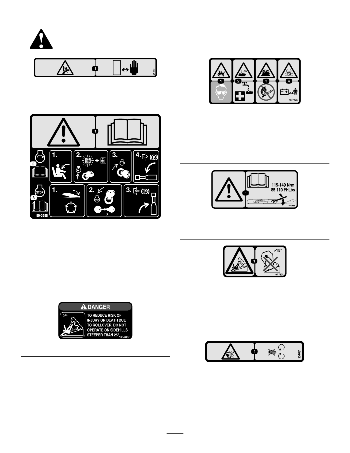
94-3353
1.Crushinghazardofhand—keepyourhandsasafedistance
away.
93-7276
1.Explosionhazard—weareyeprotection.
2.Causticliquid/chemicalburnhazard—toperformrstaid,
ushwithwater.
3.Firehazard—nore,openames,orsmoking.
4.Poisonhazard—keepchildrenasafedistancefromthe
battery.
99-3558
(CEonly)
1.Warning—readtheOperator’sManual.
2.Tostarttheengine,sitontheseatandrotatetheignition
keytoOn/Preheatuntiltheglowplugindicatorlightgoes
out.Rotatethekeytostartanddisengagetheparking
brake.ReadtheOperator’sManualforfurtherinstructions.
3.Tostoptheengine,disengagethecuttingunits,rotatethe
ignitionkeytoOff,andremovethekey.Engagetheparking
brake.ReadtheOperator’sManualforfurtherinstructions.
100-4837
93-7818
1.Warning—readtheOperator'sManualforinstructionson
torquingthebladebolt/nutto115-149N-m(85-110ft-lb).
107-7801
*Thissafetydecalincludesaslopewarningrequiredonthemachineforcomplianceto
theEuropeanLawnMowerSafetyStandardEN836:1997.Theconservativemaximum
slopeanglesindicatedforoperationofthismachineareprescribedbyandrequiredby
thisstandard.
1.Tippinghazard—donotdriveonslopesgreaterthan15
degrees.
93-6681
(CEOnly)
1.Cutting/dismemberment—hazard,fan-stayawayfrom
movingparts.
8
Page 9
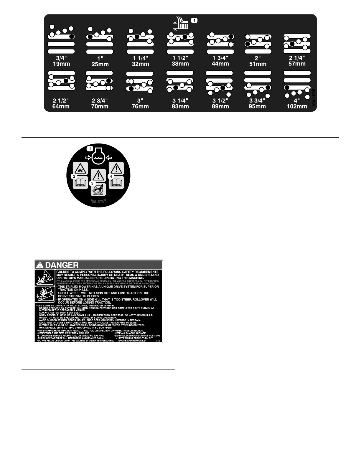
1.Heightofcut
104-1086
106-6755
1.Enginecoolantunder
pressure.
2.Explosionhazard—read
theOperator'sManual.
3.Warning—donottouchthe
hotsurface.
4.Warning—readthe
Operator'sManual.
104-0484
(Model30807,30839and30843)
9
Page 10
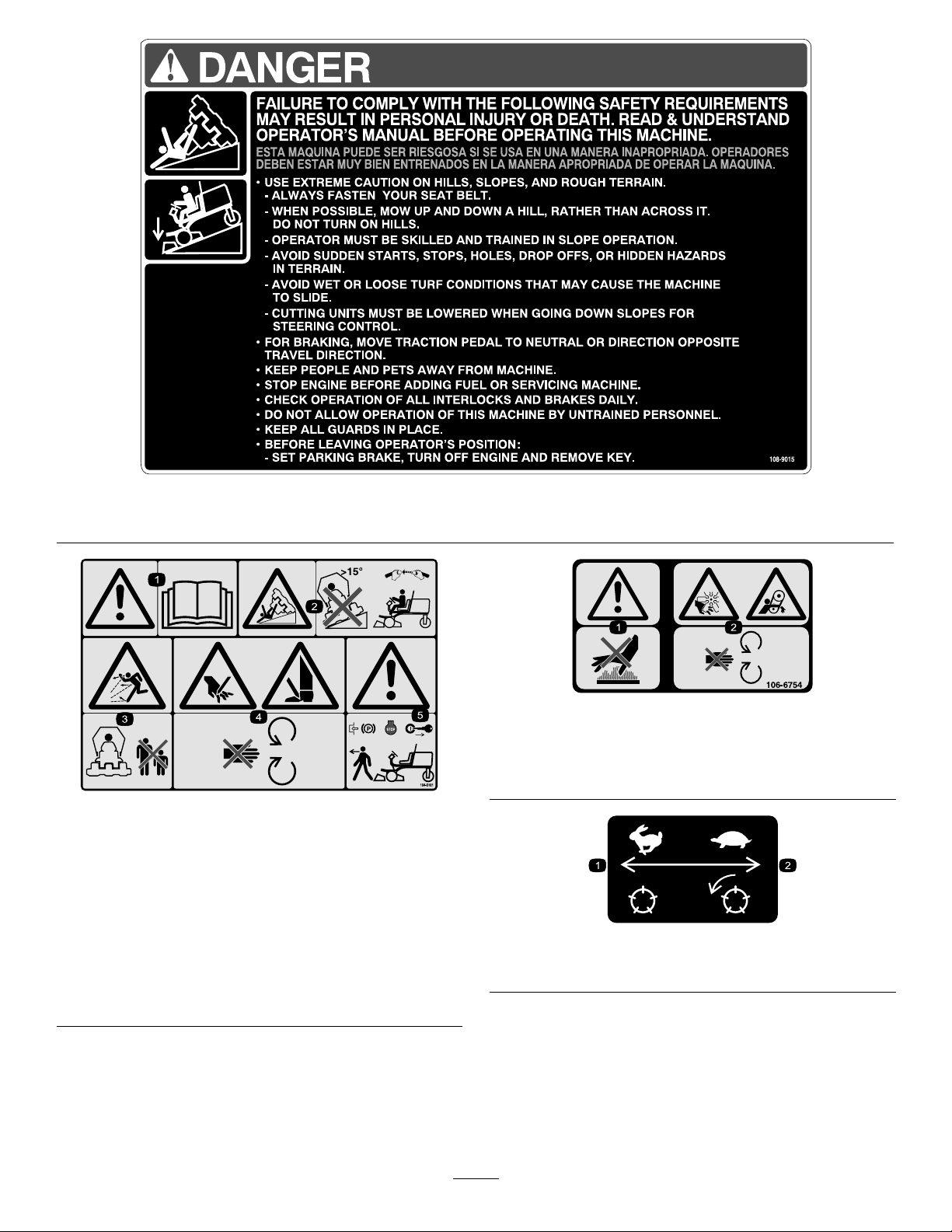
104-5181
99-3444
(CEonly)
1.Warning—readtheOperator’sManual.
2.Tippinghazard—donotdriveonslopesgreaterthan15
degreesand,iftherollbarisinstalled,weartheseatbelt.
3.Thrownobjecthazard—keepbystandersasafedistance
fromthemachine.
4.Cuttinghazardofhandorfoot—stayawayfrommoving
parts.
5.Warning—locktheparkingbrake,stoptheengine,and
removetheignitionkeybeforeleavingthemachine.
108–9015
(Model30849)
106-6754
1.Warning—donottouchthehotsurface.
2.Cutting/dismembermenthazard,fanandentanglement
hazard,belt—stayawayfrommovingparts.
99-3444
1.Reelspeed—fast
2.Reelspeed—slow
10
Page 11
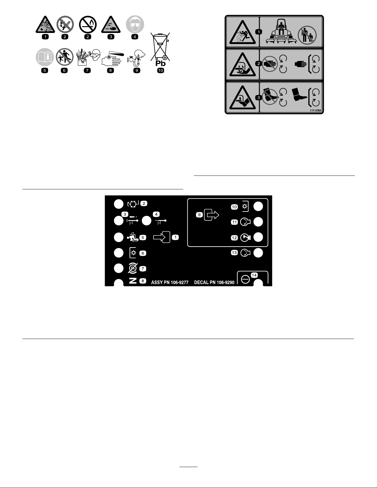
BatterySymbols
Someorallofthesesymbolsareonyourbattery
1.Explosionhazard
2.Nore,opename,or
smoking.
3.Causticliquid/chemical
burnhazard
4.Weareyeprotection9.Flusheyesimmediately
5.ReadtheOperator's
Manual.
6.Keepbystandersasafe
7.Weareyeprotection;
8.Batteryacidcancause
10.Containslead;donot
distancefromthebattery.
explosivegasescan
causeblindnessandother
injuries
blindnessorsevereburns.
withwaterandgetmedical
helpfast.
discard.
117-4764
1.Thrownobjecthazard—keepbystandersasafedistance
fromthemachine.
2.Cuttinghazardofhand,mowerblade—stayawayfrom
movingparts,keepallguardsandshieldsinplace.
3.Cuttinghazardoffoot,mowerblade—stayawayfrom
movingparts,keepallguardsandshieldsinplace.
1.Inputs5.Inseat
2.Notactive
3.Hightemperatureshutdown
4.Hightemperaturewarning8.Neutral
6.PowerT ake-off(PTO)10.PowerT akeOff(PTO)
7.ParkingbrakeOff11.Start
106-9290
9.Outputs13.Start
14.Power
12.EnergizetoRun(ETR)
11
Page 12

117-5103
(Models30849,30839and30843)
121–3532
(Model30807)
1.ReadtheOperator’sManual.4.Optionalligh—15A
2.SCM-2A5.Systemgauges—10A
3.Main—15A6.Enginestart—10A
12
Page 13
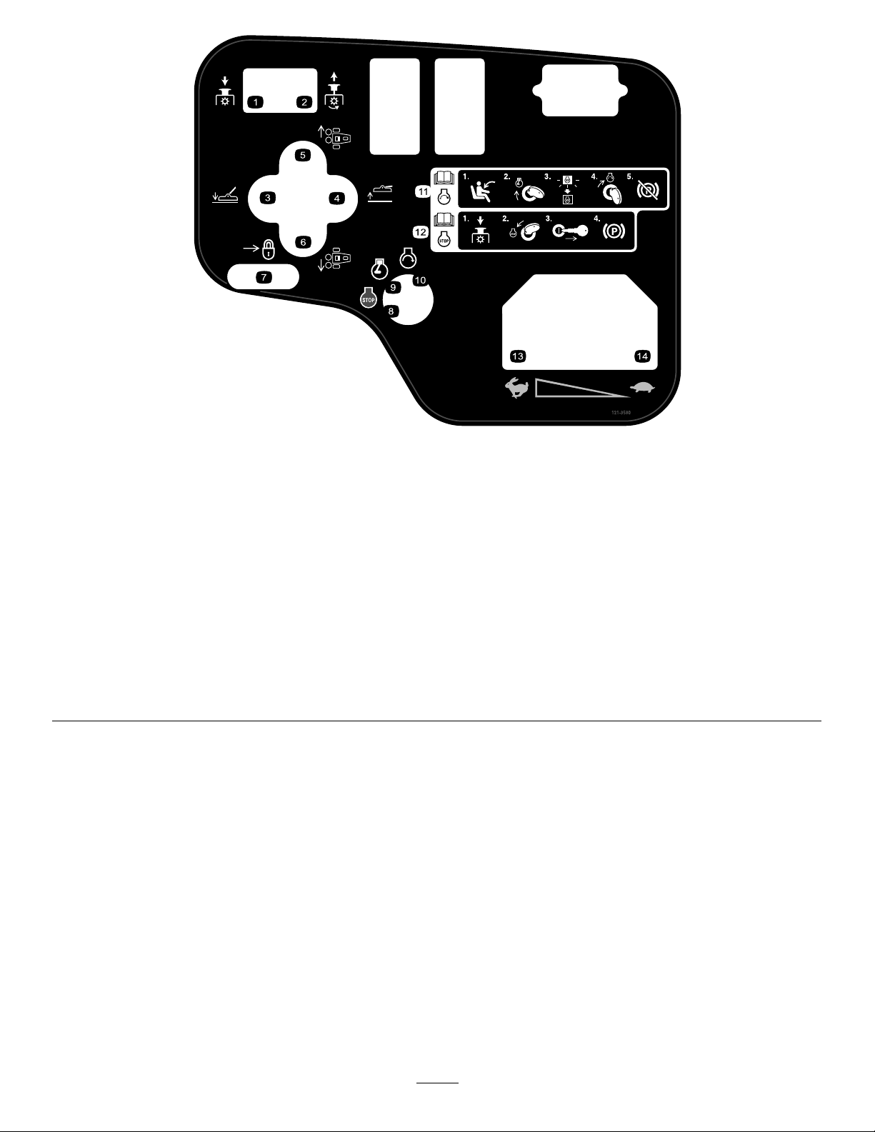
121–3580
(Models30807,30839and30843)
1.PushdowntodisengagePTO.
2.PulluptoengagePTO.
3.Lowerthedeck.10.Engine—run
4.Raisethedeck.
5.Middleandright-handdecks
6.Middleandlef-handdecks
7.Slidetolock14.Slow
8.Engine—stop
9.Engine—run
11.Formoreinformationonstartingtheengine,readthe
Operator’sManual—1)Sitintheoperator’sposition;2)Turn
theignitionkeytotheenginerunposition;3)Waitforthe
enginepreheatlighttoturnoff;4)Turntheignitionkeytothe
enginestartposition;5)Disengagetheparkingbrake.
12.Formoreinformationonstoppingtheengine,readthe
Operator’sManual—1)DisengagethePTO;2)Turnthe
ignitionkeytotheenginestopposition;3)Removethekey
fromtheignition;4)Engagetheparkingbrake.
13.Fast
13
Page 14
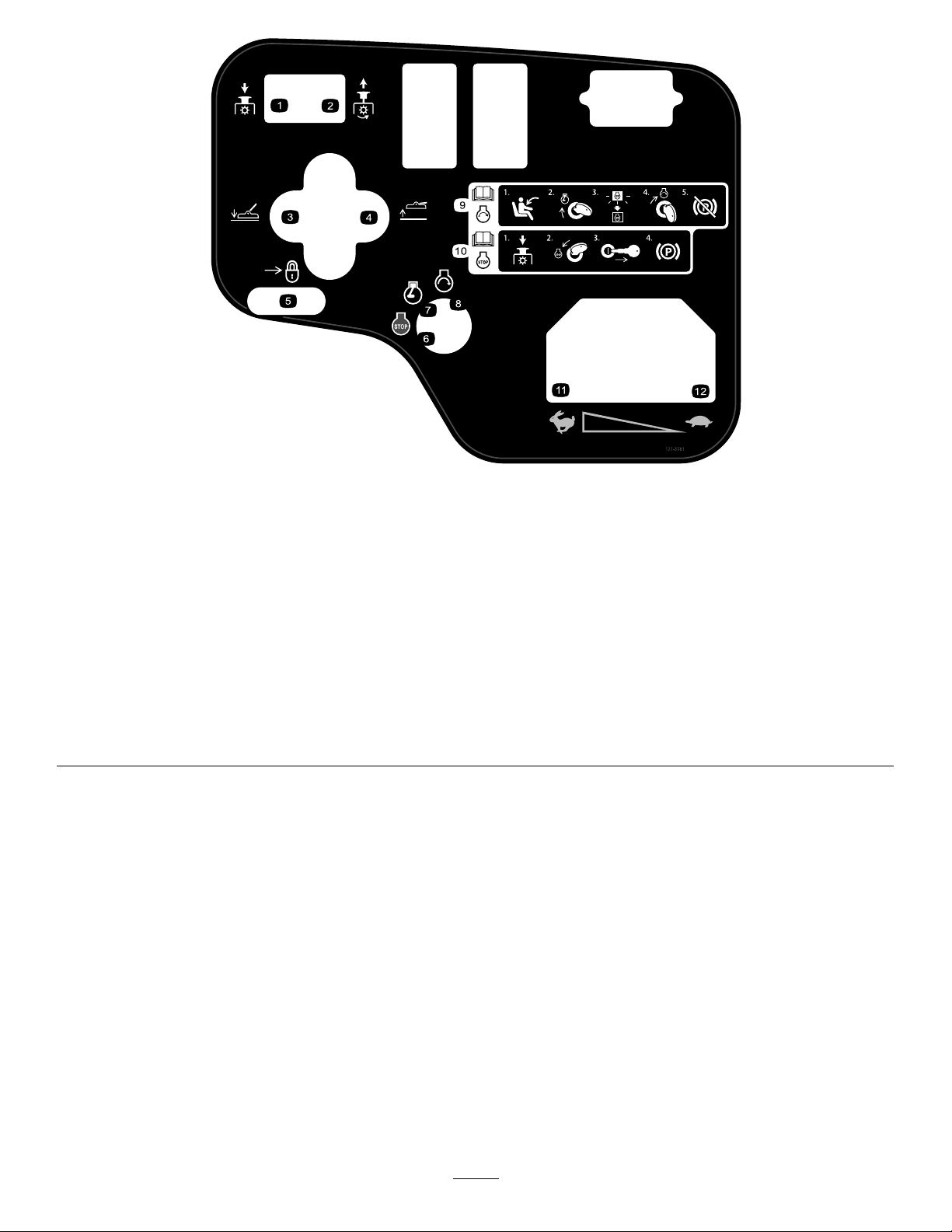
121–3581
(Model30849)
1.PushdowntodisengagePTO.
2.PulluptoengagePTO.
3.Lowerthedeck.
4.Raisethedeck.
5.Slidetolock
6.Engine—stop
7.Engine—run
8.Engine—run
9.Formoreinformationonstartingtheengine,readthe
Operator’sManual—1)Sitintheoperator’sposition;2)Turn
theignitionkeytotheenginerunposition;3)Waitforthe
enginepreheatlighttoturnoff;4)Turntheignitionkeytothe
enginestartposition;5)Disengagetheparkingbrake.
10.Formoreinformationonstoppingtheengine,readthe
Operator’sManual—1)DisengagethePTO;2)Turnthe
ignitionkeytotheenginestopposition;3)Removethekey
fromtheignition;4)Engagetheparkingbrake.
11.Fast
12.Slow
14
Page 15

Setup
LooseParts
Usethechartbelowtoverifythatallpartshavebeenshipped.
ProcedureDescription
1
2
3
4
5
6
7
8
Nopartsrequired
Inclinometer1
Warningdecal(104–5181)
Warningdecal(99–3558)
Warningdecal(107–1972)
Lockbracket1
Rivet2
Washer1
Screw,1/4x2inches
Locknut,1/4inch
Exhaustguard1
Self-tappingscrew
Nopartsrequired
Nopartsrequired
Nopartsrequired
Qty.
Use
–
1
1
3
1
1
4
–
–
–
Activate,charge,andconnectthe
battery.
Checktheangleindicator(Models
30839,30843and30807only)
InstalltheCEdecals,ifrequired.
InstalltheHoodLatch(CE).
InstalltheExhaustGuard(CE).
Adjusttheliftarms.
Rearballast.
Adjustthecarrierframe
9
10
11
Nopartsrequired
Nopartsrequired
Nopartsrequired
MediaandAdditionalParts
Description
Ignitionkeys2
Operator'sManual
EngineOperator'sManual
PartsCatalog
Operatorvideo
DeclarationofConformity
Note:Determinetheleftandrightsidesofthemachine
fromthenormaloperatingposition.
–
–
–
Qty.
Starttheengine.
1
1
1Usetolookupandorderparts.
1
1
Readbeforeoperatingthemachine.
Viewbeforeoperatingthemachine.
EnsureCEcompliance.
Adjusttheheight-of-cut
Adjusttherollerscraper(Optional)
Installthemulchingbafe(Optional)
Use
15
Page 16
3.Removethellercapsfromthebatteryandslowlyll
eachcelluntilelectrolyteisjustabovetheplates.
1
Activating,Charging,and
ConnectingtheBattery
NoPartsRequired
Procedure
WARNING
CALIFORNIA
Proposition65Warning
Batteryposts,terminals,andrelated
accessoriescontainleadandleadcompounds,
chemicalsknowntotheStateofCalifornia
tocausecancerandreproductiveharm.
W ash hands after handling .
Note:Ifthebatteryisnotlledwithelectrolyteoractivated,
bulkelectrolytewith1.260specicgravitymustbepurchased
fromalocalbatterysupplyoutletandaddedtothebattery.
DANGER
Batteryelectrolytecontainssulfuricacidwhichisa
deadlypoisonandcausessevereburns.
•Donotdrinkelectrolyteandavoidcontactwith
skin,eyes,orclothing.Wearsafetyglassesto
shieldyoureyesandrubberglovestoprotect
yourhands.
•Fillthebatterywherecleanwaterisalways
availableforushingtheskin.
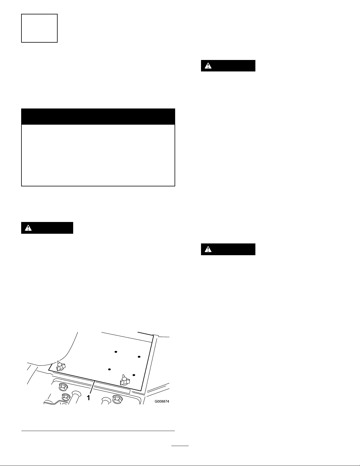
1.Openthehood.
2.Removethebatterycover(Figure3).
4.Installthellercapsandconnecta3to4ampbattery
chargertothebatteryposts.Chargethebatteryata
rateof3to4amperesfor4to8hours.
WARNING
Chargingthebatteryproducesgassesthatcan
explode.
•Keepsparksandamesawayfrombattery.
•Neversmokenearthebattery.
5.Whenthebatteryischarged,disconnectthecharger
fromtheelectricaloutletandbatteryposts.
6.Removethellercaps.Slowlyaddelectrolytetoeach
celluntilthelevelisuptothellring.Installtheller
caps.
Important:Donotoverllthebattery.Electrolyte
willoverowontootherpartsofthemachineand
severecorrosionanddeteriorationwillresult.
7.Installthepositivecable(red)tothepositive(+)
terminalandthenegativecable(black)tothenegative
(–)terminalofthebatteryandsecurethemwithbolts
andnuts(Figure4).Makesurethatthepositive(+)
terminalisallofthewayontothepostandthecable
ispositionedsnugtothebattery.Thecablemustnot
contactthebatterycover.
WARNING
Incorrectbatterycableroutingcoulddamage
thetractorandcablescausingsparks.Sparks
cancausethebatterygassestoexplode,
resultinginpersonalinjury.
•Alwaysdisconnectthenegative(black)
batterycablebeforedisconnectingthe
positive(red)cable.
•Alwaysconnectthepositive(red)battery
cablebeforeconnectingthenegative
(black)cable.
1.Batterycover
Figure3
16
Page 17
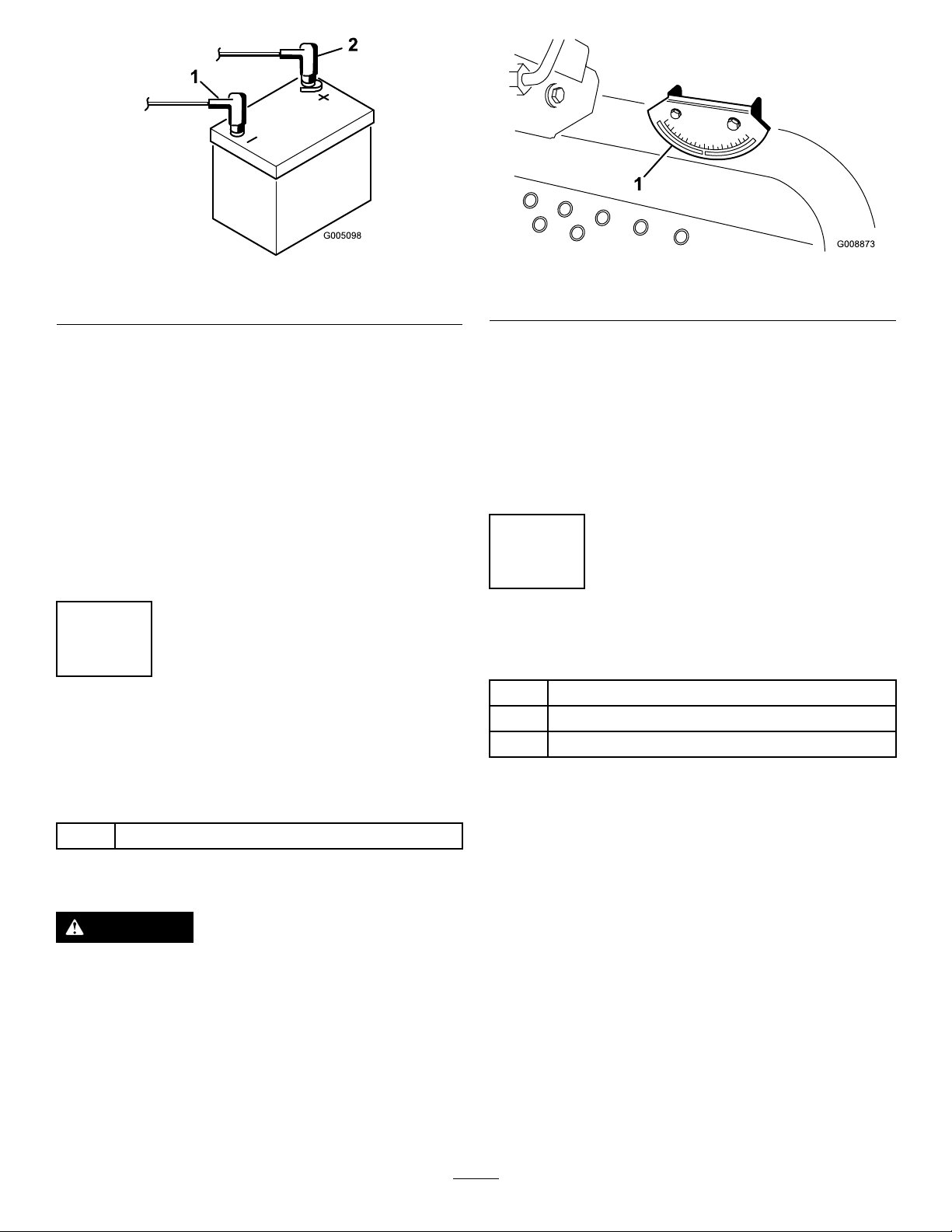
Figure4
1.Positive(+)batterycable2.Negative(–)batterycable
Figure5
1.Angleindicator
Important:Ifthebatteryiseverremoved,make
surethatthebatteryclampboltsareinstalledwith
theboltheadspositionedonthebottomsideand
thenutsonthetopside.Iftheclampboltsare
reversed,theymayinterferewiththehydraulic
tubeswhenshiftingthecuttingunits.
8.CoatbothbatteryconnectionswithGrafo112X(skin
over)grease,T oroPartNo.505-47,petroleumjelly ,or
lightgreasetopreventcorrosion.
9.Slidetherubberbootoverthepositiveterminalto
preventapossibleshortfromoccurring.
10.Installthebatterycover.
2
CheckingtheAngleIndicator (Models30839,30843and 30807only)
3.Iftheinclinometerdoesnotreadzerodegrees,move
themachinetoalocationwhereazerodegreereading
isobtained.Theangleindicator,mountedonthe
machine,shouldnowreadzerodegreesaswell.
4.Iftheangleindicatordoesnotreadzerodegrees,
loosenthetwoscrewsandnutssecuringtheangle
indicatortothemountingbracket,adjusttheindicator
toobtainazerodegreereading,andtightenthebolts.
3
InstallingtheCEDecals
Partsneededforthisprocedure:
1
Warningdecal(104–5181)
1
Warningdecal(99–3558)
3
Warningdecal(107–1972)
Partsneededforthisprocedure:
1Inclinometer
Procedure
DANGER
Toreduceriskofinjuryordeathduetorollover,do
notoperatethemachineonsidehillssteeperthan
25º.
1.Parkthemachineonaat,levelsurface.
2.Verifythatthemachineislevelbyplacingahandheld
inclinometer(suppliedwiththemachine)ontheframe
crossrail,bythefueltank(Figure5).Theinclinometer
shouldreadzerodegreeswhenviewedfromthe
operator’sposition.
Procedure
IfthismachinewillbeusedforCE,afxtheCEwarning
decalsoverthecorrespondingEnglishwarningdecals.
17
Page 18
4
G012628
1
2
G012629
1
2
G012630
1
G012631
1
2
3
InstallingtheHoodLatch(CE
Only)
Partsneededforthisprocedure:
1Lockbracket
2Rivet
1Washer
1
Screw,1/4x2inches
1
Locknut,1/4inch
Procedure
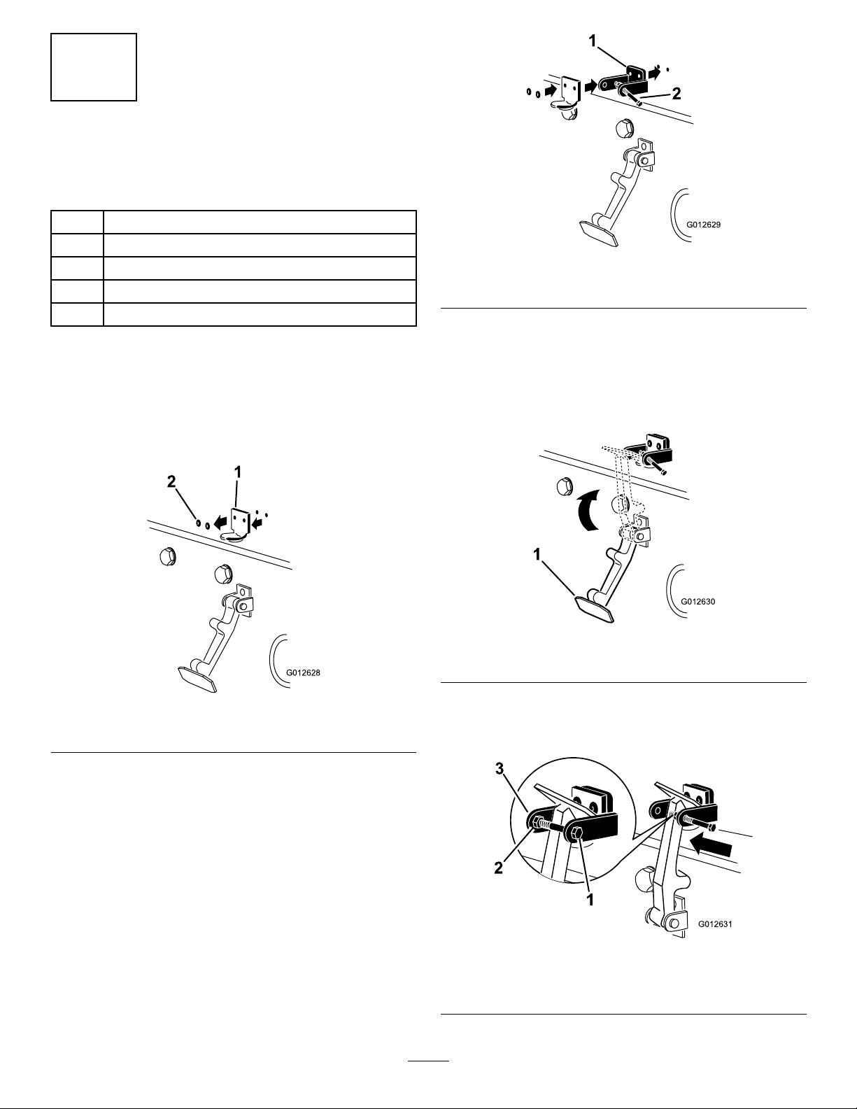
1.Unhookthehoodlatchfromthehoodlatchbracket.
2.Removethe(2)rivetssecuringthehoodlatchbracket
tothehood(Figure6).Removethehoodlatchbracket
fromthehood.
Figure7
1.CElockbracket
4.Alignthewasherswiththeholesontheinsideofthe
hood.
5.Rivetthebracketsandthewasherstothehood(Figure
7).
6.Hookthelatchontothehoodlatchbracket(Figure8).
2.Boltandnutassembly
Figure8
1.Hoodlatch
Figure6
1.Hoodlatchbracket2.Rivets
3.Whilealigningthemountingholes,positiontheCE
lockbracketandthehoodlatchbracketontothehood.
Thelockbracketmustbeagainstthehood(Figure7).
Donotremoveboltandnutassemblyfromthelock
bracketarm.
7.Screwtheboltintotheotherarmofhoodlockbracket
tolockthelatchinposition(Figure9).Tightenbolt
securelybutdonottightennut.
Figure9
1.Bolt
2.Nut
3.Armofhoodlockbracket
18
Page 19

5
InstallingtheExhaustGuard
(CEOnly)
Partsneededforthisprocedure:
1Exhaustguard
4
Self-tappingscrew
oorplatebracketis5to8mm(0.18to0.32inches)
(Figure11).
Procedure
1.Positiontheexhaustguardaroundthemuferwhile
aligningthemountingholeswiththeholesintheframe
(Figure10).
Figure11
cuttingunitsremovedforclarity
1.Liftarm3.Clearance
2.Floorplatebracket
Iftheclearanceisnotinthisrange,adjustitasfollows:
A.Backoffthestopbolts(Figure12).
Figure12
1.Stopbolt3.Clearance
2.Liftarm
Figure10
1.Exhaustguard
2.Securetheexhaustguardtotheframewith4
self-tappingscrews(Figure10).
6
AdjustingtheLiftArms
NoPartsRequired
Procedure
1.Starttheengine,raisethecuttingunits,andcheckto
ensurethattheclearancebetweeneachliftarmandthe
B.Backoffthejamnutonthecylinder(Figure13).
Figure13
1.Frontcylinder2.Jamnut
C.Removethepinfromtherodendandrotatethe
clevis.
19
Page 20

D.Installthepinandchecktheclearance.Repeat
theprocedureifrequired.
E.Tightentheclevisjamnut.
2.Checktomakesurethattheclearancebetweeneachlift
armandstopboltis0.13to1.02mm(0.005to0.040
inches)(Figure12).Iftheclearanceisnotinthisrange,
adjustthestopboltstoattainclearance.
3.Starttheengine,raisethecuttingunits,andcheckto
makesurethattheclearancebetweenthewearstrap
onthetopoftherearcuttingunitwearbarandthe
bumperstrapis0.51to2.54mm(0.02to0.10inches)
(Figure14).
Figure14
1.Wearbar2.Bumperstrap
Iftheclearanceisnotinthisrange,adjusttherear
cylinderasfollows:
7
RearBallast
NoPartsRequired
Procedure
Models30843,30839and30807conformtoCENstandard
EN836:1997andANSIstandardB71.4-2004standardwhen
22.6kg(50lbs)ofcalciumchlorideballastisaddedtothe
rearwheels.Model30849conformstoCENstandardEN
836:1997andANSIstandardB71.4-2004standardwhen30
kg.(67lbs)ofcalciumchlorideballastisaddedtotherear
wheelandweight,partno.104-3965isaddedtotherearfork.
Important:Ifapunctureoccursinatirewithcalcium
chloride,removethemachinefromtheturfasquickly
aspossible.Topreventpossibledamagetotheturf,
immediatelysoaktheaffectedareawithwater.
8
Note:Iftherearliftarmclunksduringtransport,
clearancecanbereduced.
A.Lowerthecuttingunitsandbackoffthejamnut
onthecylinder(Figure15).
Figure15
1.Rearcylinder2.Adjustingnut
B.Graspthecylinderrodclosetothenutwitha
pliersandragandrotatetherod.
C.Raisethecuttingunitsandchecktheclearance.
Repeattheprocedureifrequired.
D.Tightentheclevisjamnut.
AdjustingtheCarrierFrame
NoPartsRequired
AdjustingtheFrontCuttingDecks
Thefrontandrearcuttingdecksrequiredifferentmounting
positions.Thefrontcuttingdeckhastwomountingpositions
dependingonwhatheight-of-cutanddegreeofdeckrotation
youdesire.
1.Forheightsofcutinthe2to7.6cm(3/4to3inch)
range,mountthefrontcarrierframesinthelowerfront
mountingholes(Figure16).
Note:Thispermitsmoreuptravelofthecutting
decksrelativetotractorwhenapproachingquickuphill
changesinterrain.Itdoeshoweverlimittheclearance
ofthechambertothecarrierwhencrestingsharp
knolls.
Important:Lackofclearanceatthefrontstopsorrear
wearbarcoulddamagetheliftarms.
20
Page 21
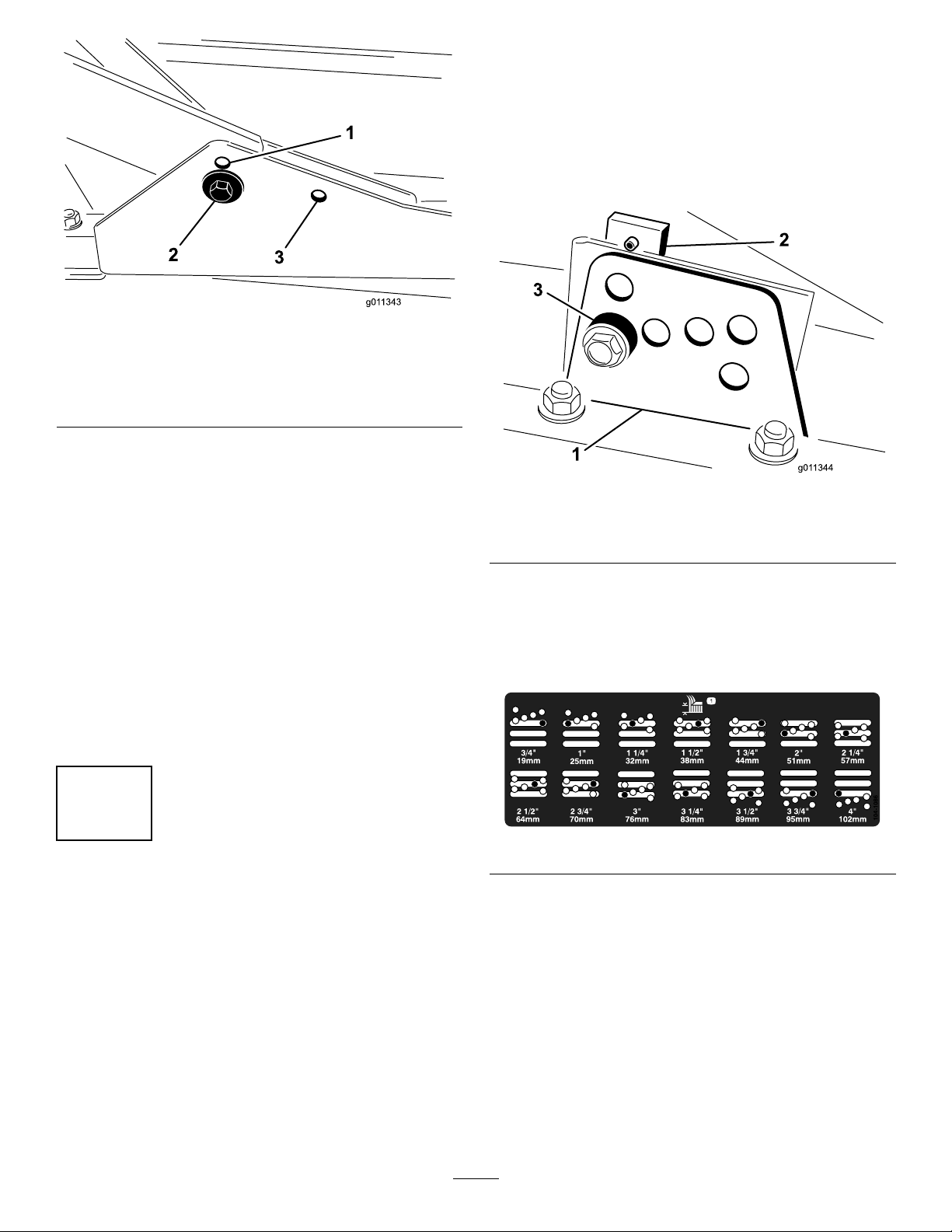
Figure16
cuttingunitstotheright,removetherearcuttingunit,
andslideitouttotherightside.
1.Lowerthecuttingdecktotheground,stoptheengine,
andremovethekeyfromignitionswitch.
2.Loosentheboltsecuringeachheight-of-cutbracketto
theheight-of-cutplate(frontandeachside)(Figure17).
3.Beginningwithfrontadjustment,removethebolt.
1.Frontdeckmountinghole
(upper)
2.Frontdeckmountinghole
(lower)
2.Forheightsofcutinthe6.3to10cm(2-1/2to4inch)
range,mountthefrontcarrierframesintheupper
frontmountingholes(Figure16).
Note:Thisincreasesthechambertocarrierclearance
duetothehigherpositionofthecuttingchamber,but
willcausethecuttingdecktoreachtheirmaximumup
travelsooner.
3.Reardeckmountinghole
AdjustingtheRearCuttingDeck
Thefrontandrearcuttingdecksrequiredifferentmounting
positions.Therearcuttingdeckhasonemountingposition
forproperalignmentwiththesidewinderunderframe.
Forallheightsofcut,mounttherearcuttingdeckintherear
mountingholes(Figure16).
Figure17
1.Heightofcutbracket3.Spacer
2.Heightofcutplate
4.Whilesupportingthechamber,removethespacer
(Figure17).
5.Movethechambertothedesiredheight-of-cutand
installaspacerintothedesignatedheight-of-cuthole
andslot(Figure18).
9
AdjustingtheHeight-of-Cut
NoPartsRequired
Procedure
Important:Thiscuttingdeckoftencutsapproximately
6mm(1/4inch)lowerthanareelcuttingunitwiththe
samebenchsetting.Itmaybenecessarytohavethese
rotarycuttingdeck’sbenchset6mm(1/4inch)above
thatofreelscuttinginthesamearea.
Important:Accesstotherearcuttingunitsisgreatly
improvedbyremovingthecuttingunitfromthetractor.
IftheunitisequippedwithaSidewinder®,sidewindthe
Figure18
6.Positionthetappedplateinlinewiththespacer.
7.Installtheboltngertight.
8.Repeatsteps4-7foreachsideadjustment.
9.Tightenallthreeboltsto41N-m(30ft-lb).Always
tightenthefrontboltrst.
Note:Adjustmentsofmorethan3.8cm(1-1/2
inches)mayrequiretemporaryassemblytoan
intermediateheighttopreventbinding(e.g.changing
from3.1to7cm(1.25to2.75inch)height-of-cut).
21
Page 22

10
G011346
1
2
3
G011347
1
AdjustingtheRollerScraper
(Optional)
NoPartsRequired
Procedure
Theoptionalrearrollerscraperisdesignedtoworkbest
whenthereisanevengapof0.5to1mm(0.020–0.040inch)
betweenthescraperandroller.
1.Loosenthegreasettingandthemountingscrew
(Figure19).
Figure19
1.Rollerscraper
2.Mountingscrew
2.Slidethescraperupordownuntilagapof0.5to1
mm(0.020to0.040inch)isachievedbetweentherod
andtheroller.
3.Securethegreasettingandscrewto41N-m(30ft-lb)
inanalternatingsequence.
3.Greasetting
Figure20
1.Mulchingbafe
3.Verifythatmulchingbafedoesnotinterferewith
thetipofthebladeanddoesnotprotrudeinsidethe
surfaceoftherearchamberwall.
WARNING
Donotusethehighliftbladewiththe
mulchingbafe.Thebladecouldbreak,
resultinginpersonalinjuryordeath.
11
InstallingtheMulchingBafe
(Optional)
NoPartsRequired
Procedure
1.Thoroughlycleandebrisfromthemountingholeson
therearwallandleftsidewallofthechamber.
2.Installthemulchingbafeintherearopeningand
secureitwith5angeheadbolts(Figure20).
22
Page 23

ProductOverview
Controls
TiltSteeringLever
Pullthetiltsteeringlever(Figure21)backtotiltthesteering
wheeltothedesiredposition.Thenpushtheleverforward
totighten.
IndicatorSlot
Models30839,30849&30807only
Theslotintheoperatorplatform(Figure21)indicateswhen
thecuttingunitsareinthecenterposition.
AngleIndicator
Models30839,30843&30807only
Theangleindicator(Figure21)indicatesthesidehillangleof
themachineindegrees.
Figure21
1.Forwardtractionpedal4.Tiltsteeringlever
2.Reversetractionpedal5.Indicatorslot
3.Mow/transportslide
6.Angleindicator
TractionPedals
Pressthetractionforwardpedal(Figure21)tomoveforward.
Presstractionreversepedal(Figure21)tomovebackwardor
toassistinstoppingwhenmovingforward.Also,allowthe
pedaltomoveormoveittotheneutralpositiontostopthe
machine.
Mow/TransportSlide
Usingyourheel,movethemow/transportslide(Figure21)
tothelefttotransportandtotherighttomow.Thecutting
unitswillonlyoperateinthemowposition.
Important:Themowspeedissetatthefactoryto9.7
km/h(6MPH).Itcanbeincreasedordecreasedby
adjustingthespeedstopscrew(Figure22).
IgnitionSwitch
Theignitionswitch(Figure23),usedtostart,stop,and
preheattheengine,hasthreepositions:Off,On/Preheat,and
Start.RotatethekeytotheOn/Preheatpositionuntilthe
glowplugindicatorlightgoesout(approximately7seconds);
thenrotatethekeytotheStartpositiontoengagethestarter
motor.Releasethekeywhentheenginestarts.Thekeywill
moveautomaticallytotheOn/Runposition.T oshutthe
engineoff,rotatethekeytotheOffposition.Removethekey
fromtheswitchtopreventaccidentalstarting.
1.Speedstopscrew
Figure22
Figure23
1.Throttle
2.Hourmeter
3.Temperaturelight9.Ignitionswitch
4.Oilpressurelight
5.Glowplugindicatorlight1 1.Liftleverlock
6.Alternatorlight
7.Cuttingunitdriveswitch
8.Cuttingunitshiftlever
10.Parkingbrake
Throttle
Movethethrottle(Figure23)forwardtoincreasetheengine
speedandrearwardtodecreasetheenginespeed.
23
Page 24

CuttingUnitDriveSwitch
ParkingBrake
Thecuttingunitdriveswitch(Figure23)hastwopositions:
EngageandDisengage.Therockerswitchoperatesasolenoid
valveonthevalvebanktodrivethecuttingunits.
HourMeter
Thehourmeter(Figure23)indicatesthetotalhoursof
machineoperation.Thehourmeterstartstofunction
wheneverthekeyswitchisOn.
CuttingUnitShiftLever
Tolowerthecuttingunitstotheground,movethecutting
unitshiftlever(Figure23)forward.Thecuttingunitswillnot
dropunlesstheengineisrunning.Toraisethecuttingunits,
pulltheshiftleverrearwardtotheRaiseposition.
OnModels30839,30849&30807,movethelevertothe
rightorlefttomovethecuttingunitsinthesamedirection.
Thisshouldonlybedonewhenthecuttingunitsareraisedor
iftheyareonthegroundandthemachineismoving.
Note:Theleverdoesnothavetobeheldintheforward
positionwhilethecuttingunitsarelowered.
Whenevertheengineisshutoff,engagetheparkingbrake
(Figure23)topreventaccidentalmovementofthemachine.
Toengagetheparkingbrake,pulluponthelever.Theengine
willstopifyoupressthetractionpedalwiththeparkingbrake
engaged.
LiftLeverLock
Movetheliftleverlock(Figure23)rearwardtopreventthe
cuttingunitsfromdropping.
FuelGauge
Thefuelgauge(Figure24)registerstheamountoffuelin
thetank.
DANGER
OnModels30839,30849&30807,shiftingthe
cuttingunitsdownhilldecreasesmachinestability.
Thiscouldcausearollover,whichmayresultin
personalinjuryordeath.
Shiftthecuttingunitsuphillwhileonasidehill.
EngineCoolantTemperatureWarning
Light
Thetemperaturewarninglight(Figure23)glowsiftheengine
coolanttemperatureishigh.Ifthetractionunitisnotstopped
andthecoolanttemperaturerisesanother10°F,theengine
willkill.
OilPressureWarningLight
Theoilpressurewarninglight(Figure23)glowsiftheengine
oilpressuredropsbelowasafelevel.
AlternatorLight
Figure24
1.Foreandaftlever
2.Fuelgauge
ForeandAftSeatAdjustments
Movethelever(Figure24)onthesideoftheseatoutward,
slidetheseattothedesiredposition,andreleasethelever
tolocktheseatintoposition.
Thealternatorlight(Figure23)shouldbeoffwhentheengine
isrunning.Ifitison,thechargingsystemshouldbechecked
andrepairedasnecessary.
GlowPlugIndicator
Theglowplugindicatorlight(Figure23)willglowwhenthe
glowplugsareoperating.
24
Page 25

Specications
Note:Specicationsanddesignaresubjecttochange
withoutnotice.
TractionUnit
OverallWidth-68inchwidth
ofcut
OverallWidth-72inchwidth
ofcut
Length
HeighttotopofROPS180cm(70.8inches)
WheelBase
TrackWidth
GroundClearance15.3cm(6inches)
Weightwithcuttingunits
Models30839,
30843and30807
Model30849
CuttingDeck
Length
Width
Height
Weight
Attachments/Accessories
AselectionofToroapprovedattachmentsandaccessoriesis
availableforusewiththemachinetoenhanceandexpand
itscapabilities.ContactyourAuthorizedServiceDealeror
Distributororgotowww .Toro.comforalistofallapproved
attachmentsandaccessories.
182cm(71.8inches)
193cm(75.8inches)
295cm(116inches)
149cm)(58.5inches)
145cm(57inches)
963kg(2,124lb)
952kg(2,099lb)
86.4cm(34inches)
86.4cm(34inches)
24.4cm(9.6inches)
tocarriermount
26.7cm(10–1/2inches)
at3/4inchheightofcut
34.9cm(13–3/4inches)at
4inchheightofcut
88kg(195pounds)
Operation
Note:Determinetheleftandrightsidesofthemachine
fromthenormaloperatingposition.
CheckingtheEngineOilLevel
ServiceInterval:Beforeeachuseordaily
Theengineisshippedwithoilinthecrankcase;however,the
oillevelmustbecheckedbeforeandaftertheengineisrst
started.
Crankcasecapacityisapproximately2.8liters(4quarts)with
thelter.
Usehigh-qualityengineoilthatmeetsthefollowing
specications:
•APIClassicationLevelRequired:CH-4,CI-4orhigher.
•Preferredoil:SAE15W-40(above0ºF(-17ºC))
•Alternateoil:SAE10W-30or5W-30(alltemperatures)
Note:T oroPremiumEngineoilisavailablefromyour
distributorineither15W-40or10W-30viscosity.Seethe
partscatalogforpartnumbers.
Note:Thebesttimetochecktheengineoiliswhenthe
engineiscoolbeforeithasbeenstartedfortheday.Ifithas
alreadybeenrun,allowtheoiltodrainbackdowntothe
sumpforatleast10minutesbeforechecking.Iftheoillevel
isatorbelowthe“add”markonthedipstick,addoiltobring
theoilleveltothe“full”mark.DONOTOVERFILL.If
theoillevelisbetweenthe“full”and“add”marks,nooil
additionisrequired.
1.Positionthemachineonalevelsurface.
2.Removethedipstick(Figure25)andwipeitwitha
cleanrag.
Figure25
1.Dipstick
3.Pushthedipstickdownintothedipsticktubeandmake
surethatitisseatedfully.Pullthedipstickoutand
checktheoillevel.
4.Iftheoillevelislow,removetheoilllcap(Figure26)
andgraduallyaddsmallquantitiesofoil,checkingthe
25
Page 26

levelfrequently,untilthelevelreachestheFullmark
onthedipstick.
Figure26
1.Oilllcap
5.Installtheoilllcapandclosethehood.
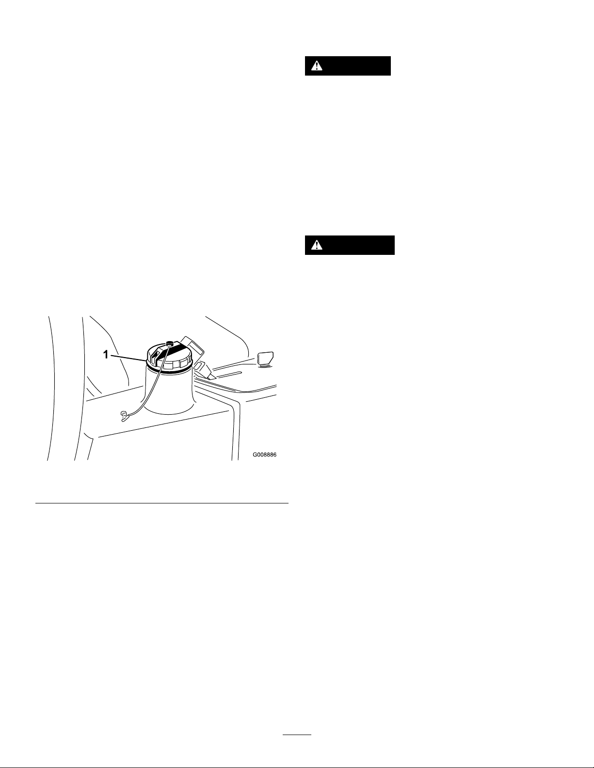
1.Cleantheareaaroundthefueltankcap(Figure27).
2.Removethefueltankcap.
3.Fillthetanktothebottomofthellerneck.Donot
overll.Installthecap.
4.Topreventarehazard,wipeupanyfuelthatmay
havespilled.
Figure27
FillingtheFuelTank
Useonlyclean,freshdieselfuelorbiodieselfuelswithlow
(<500ppm)orultralow(<15ppm)sulfurcontent.The
minimumcetaneratingshouldbe40.Purchasefuelin
quantitiesthatcanbeusedwithin180daystoensurefuel
freshness.
Thefueltankcapacityisapproximately42liters(11gallons).
Usesummergradedieselfuel(No.2–D)attemperatures
above20degreesF(–7degreesC)andwintergrade(No.
1-DorNo.1-D/2-Dblend)belowthattemperature.Useof
wintergradefuelatlowertemperaturesprovideslowerash
pointandcoldowcharacteristicswhichwilleasestarting
andreducefuellterplugging.
Useofsummergradefuelabove20degreesF(-7degreesC)
willcontributetowardlongerfuelpumplifeandincreased
powercomparedtowintergradefuel.
BiodieselReady
Thismachinecanalsouseabiodieselblendedfuelofup
toB20(20%biodiesel,80%petrodiesel).Thepetrodiesel
portionshouldbeloworultralowsulfur.Observethe
followingprecautions:
•Thebiodieselportionofthefuelmustmeetspecication
ASTMD6751orEN14214.
•TheblendedfuelcompositionshouldmeetASTMD975
orEN590.
•Paintedsurfacesmaybedamagedbybiodieselblends.
•UseB5(biodieselcontentof5%)orlesserblendsincold
weather
•Monitorseals,hoses,gasketsincontactwithfuelasthey
maybedegradedovertime.
•Fuellterpluggingmaybeexpectedforatimeafter
convertingtobiodieselblends.
•Contactyourdistributorifyouwishformoreinformation
onbiodiesel
1.Fueltankcap
DANGER
Undercertainconditions,dieselfuelandfuel
vaporsarehighlyammableandexplosive.A
reorexplosionfromfuelcanburnyouand
othersandcancausepropertydamage.
•Useafunnelandllthefueltankoutdoors,
inanopenarea,whentheengineisoffand
iscold.Wipeupanyfuelthatspills.
•Donotllthefueltankcompletelyfull.
Addfueltothefueltankuntilthelevelis
6to13mm(1/4to1/2inch)belowthe
bottomofthellerneck.Thisemptyspace
inthetankallowsthefueltoexpand.
•Neversmokewhenhandlingfuel,andstay
awayfromanopenameorwherefuel
fumesmaybeignitedbyaspark.
•Storefuelinaclean,safety-approved
containerandkeepthecapinplace.
CheckingtheCoolingSystem
ServiceInterval:Beforeeachuseordaily
Cleandebrisoffoftheradiatorandoilcoolerdaily(Figure
28).Cleantheradiatorhourlyifconditionsareextremely
dustyanddirty;refertoCleaningtheEngineCoolingSystem.
26
Page 27

1.Accesspanel
2.Radiator
Figure28
Figure29
3.Oilcooler
1.Expansiontank
Thecoolingsystemislledwitha50/50solutionofwater
andpermanentethyleneglycolanti-freeze.Checkthecoolant
levelatthebeginningofeachdaybeforestartingtheengine.
Thecapacityofthecoolingsystemisapproximately5.7liters
(6quarts).
CAUTION
Iftheenginehasbeenrunning,thepressurized,hot
coolantcanescapeandcauseburns.
•Donotopentheradiatorcapwhentheengine
isrunning.
•Usearagwhenopeningtheradiatorcap,and
openthecapslowlytoallowsteamtoescape.
1.Checkthecoolantlevelintheexpansiontank(Figure
29).Withacoldengine,thecoolantlevelshouldbe
approximatelymidwaybetweenthemarksontheside
ofthetank.
2.Ifthecoolantlevelislow,removetheexpansiontank
capandreplenishthesystem.Donotoverll.
3.Installtheexpansiontankcap.
CheckingtheHydraulic System
ServiceInterval:Beforeeachuseordaily—Checkthe
hydraulicuidlevel.
Themachinesreservoirislledatthefactorywith
approximately13.2liters(3.5U.S.gallons)ofhighquality
hydraulicuid.Checkthelevelofthehydraulicuid
beforetheengineisrststartedanddailythereafter.
TherecommendedreplacementuidisToroPremiumAll
SeasonHydraulicFluid(Availablein19liter(5gallon)pails
or55gallondrums.SeepartscatalogorTorodistributorfor
partnumbers.)
Alternateuids:IftheT orouidisnotavailable,other
uidsmaybeusedprovidedtheymeetallthefollowing
materialpropertiesandindustryspecications.Torodoes
notrecommendtheuseofsyntheticuid.Consultwithyour
lubricantdistributortoidentifyasatisfactoryproductNote:
Torowillnotassumeresponsibilityfordamagecausedby
impropersubstitutions,souseonlyproductsfromreputable
manufacturerswhowillstandbehindtheirrecommendation.
HighViscosityIndex/LowPourPointAnti-wearHydraulic
Fluid,ISOVG46
MaterialProperties:
Viscosity,ASTMD445cSt@40°C44to48
ViscosityIndexASTM
D2270
PourPoint,ASTMD97-34°Fto-49°F
IndustrySpecications:
VickersI-286-S(QualityLevel),VickersM-2950-S
(QualityLevel),DenisonHF-0
cSt@100°C7.9to8.5
140to160
Important:TheISOVG46Multigradeuidhasbeen
foundtoofferoptimalperformanceinawiderangeof
temperatureconditions.Foroperationinconsistently
highambienttemperatures,65°F(18°C)to120°F
(49°C),ISOVG68hydraulicuidmayofferimproved
performance.
27
Page 28
PremiumBiodegradableHydraulicFluid-MobilEAL
EnviroSyn46H
Note:Maintaintherecommendedpressureinalltiresto
ensureagoodqualityofcutandpropermachineperformance.
Important:MobilEALEnviroSyn46Histheonly
syntheticbiodegradableuidapprovedbyT oro.This
uidiscompatiblewiththeelastomersusedinToro
hydraulicsystemsandissuitableforawide-range
oftemperatureconditions.Thisuidiscompatible
withconventionalmineraloils,butformaximum
biodegradabilityandperformancethehydraulicsystem
shouldbethoroughlyushedofconventionaluid.The
oilisavailablein19liters(5gallon)containersor55
gallondrumsfromyourMobilDistributor.
Important:Manyhydraulicuidsarealmostcolorless,
makingitdifculttospotleaks.Areddyeadditivefor
thehydraulicsystemoilisavailablein20ml(2/3oz.)
bottles.Onebottleissufcientfor15-221iters(4-6U.S.
gallons)ofhydraulicoil.Orderpartno.44-2500from
yourauthorizedT orodistributor.
1.Positionthemachineonalevelsurface,lowerthe
cuttingunits,andstoptheengine.
2.Cleantheareaaroundthellerneckandcapofthe
hydraulictank(Figure30).Removethecap.
DANGER
Lowtirepressuredecreasesmachinesidehill
stability.Thiscouldcausearollover,whichmay
resultinpersonalinjuryordeath.
Donotunder-inatethetires.
TorquingtheWheelNuts
ServiceInterval:Afterthersthour
Aftertherst10hours
Every200hours
Torquethewheelnutsto61to88N-m(45to65ft-lb).
WARNING
Failuretomaintainpropertorqueofthewheelnuts
couldresultinpersonalinjury.
StartingandStoppingthe Engine
Youmayneedtobleedthefuelsystemifanyofthefollowing
situationshaveoccurred(refertoBleedingtheFuelSystem):
•Initialstartupofanewengine
•Theenginehasceasedrunningduetolackoffuel.
•Maintenancehasbeenperformeduponthefuelsystem
components;i.e.lterreplaced,etc.
Figure30
1.Hydraulictankcap
3.Removethedipstickfromthellerneckandwipeit
withacleanrag.Insertthedipstickintothellerneck;
thenremoveitandchecktheuidlevel.Theuidlevel
shouldbewithin6mm(1/4inch)ofthemarkonthe
dipstick.
4.Ifthelevelislow ,addtheappropriateuidtoraisethe
leveltothefullmark.
5.Installthedipstickandcapontothellerneck.
CheckingtheTirePressure
ServiceInterval:Beforeeachuseordaily
Thetiresareover-inatedforshipping.Therefore,release
someoftheairtoreducethepressure.Thecorrectair
pressureinthetiresis97to124kPa(14to18psi).
StartingtheEngine
1.Besurethattheparkingbrakeissetandthecutting
unitdriveswitchisintheDisengageposition.
2.Removeyourfootfromthetractionpedalandmake
surethatthepedalisintheneutralposition.
3.Movethethrottlelevertothe1/2throttleposition.
4.Insertthekeyintotheswitchandrotateittothe
On/Preheatpositionuntiltheglowplugindicatorlight
goesout(approximately7seconds);thenrotatethe
keytotheStartpositiontoengagethestartermotor.
Releasethekeywhentheenginestarts.Thekeywill
moveautomaticallytotheOn/Runposition.
Important:Topreventoverheatingofthestarter
motor,donotengagethestarterlongerthan15
seconds.After10secondsofcontinuouscranking,
wait60secondsbeforeengagingthestartermotor
again.
5.Whentheengineisstartedforthersttimeorafteran
overhauloftheengine,operatethemachineinforward
andreverseforonetotwominutes.Alsooperatethe
liftleverandcuttingunitdriveswitchtobesureof
properoperationofallparts.
28
Page 29

Turnthesteeringwheeltotheleftandrighttocheck
steeringresponse;thenshuttheengineoffandcheck
foroilleaks,looseparts,andanyothernoticeable
malfunctions.
CAUTION
Stoptheengineandwaitforallmovingparts
tostopbeforecheckingforoilleaks,loose
parts,andothermalfunctions.
StoppingtheEngine
MovethethrottlecontroltotheIdleposition,movethe
cuttingunitdriveswitchtoDisengage,androtatethestarter
keytoOff.Removethekeyfromtheswitchtoprevent
accidentalstarting.
BleedingtheFuelSystem
1.Parkthemachineonalevelsurface.Makesurethatthe
fueltankisatleasthalffull.
2.Unlatchandraisethehood.
Figure31
1.Fuelinjectionpumpbleedscrew
4.TurnthekeyintheignitionswitchtotheOnposition.
Theelectricfuelpumpwillbeginoperation,thereby
forcingairoutaroundtheairbleedscrew .Leavethe
keyintheOnpositionuntilasolidstreamoffuelows
outaroundthescrew .
5.TightenthescrewandturnthekeytoOff.
DANGER
Undercertainconditions,dieselfuelandfuel
vaporsarehighlyammableandexplosive.A
reorexplosionfromfuelcanburnyouand
othersandcancausepropertydamage.
•Useafunnelandllthefueltankoutdoors,
inanopenarea,whentheengineisoffand
iscold.Wipeupanyfuelthatspills.
•Donotllthefueltankcompletelyfull.
Addfueltothefueltankuntilthelevelis
6to13mm(1/4to1/2inch)belowthe
bottomofthellerneck.Thisemptyspace
inthetankallowsthefueltoexpand.
•Neversmokewhenhandlingfuel,andstay
awayfromanopenameorwherefuel
fumesmaybeignitedbyaspark.
•Storefuelinaclean,safety-approved
containerandkeepthecapinplace.
3.Opentheairbleedscrewonthefuelinjectionpump
(Figure31).
Note:Normallytheengineshouldstartaftertheabove
bleedingproceduresarefollowed.However,iftheengine
doesnotstart,airmaybetrappedbetweentheinjectionpump
andinjectors;refertoBleedingAirfromtheInjectors.
CheckingtheInterlockSystem
ServiceInterval:Beforeeachuseordaily
CAUTION
Ifsafetyinterlockswitchesaredisconnectedor
damagedthemachinecouldoperateunexpectedly
causingpersonalinjury.
•Donottamperwiththeinterlockswitches.
•Checktheoperationoftheinterlockswitches
dailyandreplaceanydamagedswitchesbefore
operatingthemachine.
1.Makesurethatallbystandersareawayfromtheareaof
operation.Keephandsandfeetawayfromthecutting
units.
2.Whilesittingontheseat,theenginemustnotstart
witheitherthecuttingunitswitchengagedorthe
tractionpedalengaged.Correcttheproblemifitisnot
operatingproperly.
3.Whilesittingontheseat,putthetractionpedalin
neutral,theparkingbrakeoff,andthecuttingunit
switchintheOffposition.Theengineshouldstart.
Risefromtheseatandslowlypressthetractionpedal,
theengineshouldstopinonetothreeseconds.Correct
problemifitisnotoperatingproperly.
29
Page 30

Note:Themachineisequippedwithaninterlockswitchon
theparkingbrake.Theenginewillstopifthetractionpedalis
pressedwiththeparkingbrakeengaged.
TowingtheTractionUnit
Incaseofanemergency ,themachinecanbetowedfora
shortdistance;however,Torodoesnotrecommendthisas
astandardprocedure.
Important:Donottowthemachinefasterthan3to
4km/h(2to3MPH)becausethedrivesystemmay
becomedamaged.Ifthemachinemustbemoveda
considerabledistance,transportitonatruckortrailer.
1.Locatethebypassvalveonthepump(Figure32)and
rotateit90°.
Figure32
1.Bypassvalve
usessolidstateandmechanicalcomponentstomonitorand
controlstandardelectricalfeaturesrequiredforsafeproduct
operation.
Themodulemonitorsinputsincludingneutral,parkingbrake,
PTO,start,backlap,andhightemperature.Themodule
energizesoutputsincludingPTO,Starter,andETR(energize
torun)solenoid.
Themoduleisdividedintoinputsandoutputs.Inputsand
outputsareidentiedbygreenLEDindicatorsmountedon
theprintedcircuitboard.
Thestartcircuitinputisenergizedby12VDC.Allother
inputsareenergizedwhenthecircuitisclosedtoground.
EachinputhasaLEDthatisilluminatedwhenthespecic
circuitisenergized.UsetheinputLED’ sforswitchandinput
circuittroubleshooting.
Outputcircuitsareenergizedbyanappropriatesetofinput
conditions.ThethreeoutputsincludePTO,ETR,and
START.OutputLED’ smonitorrelayconditionindicatingthe
presenceofvoltageatoneofthreespecicoutputterminals.
Outputcircuitsdonotdetermineoutputdeviceintegrityso
electricaltroubleshootingincludesoutputLEDinspection
andconventionaldeviceandwireharnessintegritytesting.
Measuredisconnectedcomponentimpedance,impedance
throughwireharness(disconnectatSCM),orbytemporarily
”testenergizing”thespeciccomponent.
2.Beforestartingtheengine,closethebypassvalveby
rotatingit90°(1/4turn).Donotstarttheenginewhen
thevalveisopen.
StandardControlModule (SCM)
TheStandardControlModuleisapottedelectronicdevice
producedinaonesizetsallconguration.Themodule
TheSCMdoesnotconnecttoanexternalcomputerorhand
helddevice,cannotbere–programmed,anddoesnotrecord
intermittentfaulttroubleshootingdata.
ThedecalontheSCMonlyincludessymbols.ThreeLED
outputsymbolsareshownintheoutputbox.AllotherLED’s
areinputs.Thechartbelowidentiesthesymbols.
Figure33
30
Page 31

HerearethelogicaltroubleshootingstepsfortheSCMdevice.
1.Determinetheoutputfaultyouaretryingtoresolve
(PTO,START,orETR).
2.MovekeyswitchtotheOnpositionandensurethat
theredpowerLEDisilluminated.
3.MoveallinputswitchestoensureallLED’schange
state.
4.Positioninputdevicesatappropriatepositionto
achievetheappropriateoutput.Usethefollowinglogic
charttodeterminetheappropriateinputcondition.
5.IfspecicoutputLEDisilluminatedwithout
appropriateoutputfunction,checkoutputharness,
connections,andcomponent.Repairasrequired.
INPUTSOUTPUTS
FunctionPower
Start
Run(Off
Unit)
Run(On
Unit)
Mow
Backlap
HiTemp
ON
——
——
—
—
——
—
In
Neutral
OO
OO
StartON
+
OOOOOOO
OO
O
Brake
ON
OO
—
———
PTOONInSeat
O
—
6.IfspecicoutputLEDisnotilluminated,checkboth
fuses.
7.IfspecicoutputLEDisnotilluminatedandinputs
areinappropriatecondition,installnewSCMand
determineiffaultdisappears.
Eachrow(across)inthelogicchartbelowidentiesinput
andoutputrequirementsforeachspecicproductfunction.
Productfunctionsarelistedintheleftcolumn.Symbols
identifyspeciccircuitconditionincluding:energizedto
voltage,closedtoground,andopentoground.
—
—
OO
HiTempBacklap
OO
OOO
OOO
—
—
Start
++
O
OOO
ETR
+
+
++
++
PTO
O
O
O
•(–)Indicatesacircuitclosedtoground.–LEDON
•(O)Indicatesacircuitopentogroundorde–energized
–LEDOFF
•(+)Indicatesanenergizedcircuit(clutchcoil,solenoid,or
startinput)LEDON.
•ABlankindicatesacircuitthatisnotinvolvedwiththe
logic.
Totroubleshoot,turnonthekeywithoutstartingtheengine.
Identifythespecicfunctionthatdoesnotworkandwork
acrossthelogicchart.Inspecttheconditionofeachinput
LED’stoensureitmatchesthelogicchart.
IftheinputLED’sarecorrect,checktheoutputLED .Ifthe
outputLEDisilluminatedbutthedeviceisnotenergized,
measureavailablevoltageattheoutputdevice,continuityof
thedisconnecteddevice,andpotentialvoltageontheground
circuit(oatingground).Repairswillvarydependingonyour
ndings.
31
Page 32

SelectingaBlade
StandardCombinationSail
Thisbladewasdesignedtoprovideexcellentliftand
dispersioninalmostanycondition.Ifmoreorlessliftand
dischargevelocityisrequired,consideradifferentblade.
Attributes:Excellentliftanddispersioninmostconditions.
AngledSail
Thebladegenerallyperformsbestinlowerheightsofcut-
1.9to6.4cm(3/4to2–1/2inch).
Attributes:
•Dischargeremainsmoreevenatlowerheightsofcut.
•Dischargehaslesstendencytothrowleftandthusa
cleanerlookaroundbunkersandfairways.
•Lowerpowerrequirementatlowerheightsanddenseturf.
HighLiftParallelSail
Thebladegenerallyperformsbetterinthehigherheightsof
cut-7to10cm(2to4inch).
Attributes:
•Moreliftandhigherdischargevelocity.
•Sparseorlimpturfispickedupsignicantlyathigher
heightsofcut.
•Wetorstickyclippingsaredischargedmoreefciently
reducingcongestioninthedeck.
•Requiresmorehorsepowertorun.
•Tendstodischargefurtherleftandcantendtowindrow
atlowerheightsofcut.
WARNING
Donotusethehighliftbladewiththemulching
bafe.Thebladecouldbreak,resultinginpersonal
injuryordeath.
AtomicBlade
Thisbladewasdesignedtoprovideexcellentleafmulching.
Attributes:Excellentleafmulching
32
Page 33

ChoosingAccessories
OptionalEquipmentCongurations
AngleSailBladeHighLiftParallelSail
GrassCutting:1.9to4.4
cm(0.75to1.75inch)
Height-of-Cut
GrassCutting:5to6.4
cm(2.00to2.50inch)
Height-of-Cut
GrassCutting:7to10
cm(2.75to4.00inch)
Height-of-Cut
LeafMulchingRecommendedforuse
ProsEvendischargeatlower
ConsDoesnotliftthegrass
Recommendedinmost
applications
Recommendedforthick
orlushturf
Mayworkwellinlushturf
withthemulchingbafe
heightofcutCleaner
lookaroundbunkersand
fairwaysLowerpower
requirements
wellinhighheightof
cutapplicationsWet
orstickygrasshas
atendencytobuild
upinthechamber,
leadingtopoorquality
ofcutandhigherpower
requirements
Blade(Donotusewith
themulchingbafe)
Mayworkwellinlightor
sparseturf
Recommendedforlight
orsparseturf
Recommendedinmost
applications
NotAllowedUsewithcombination
Moreliftandhigher
dischargevelocity
Sparseorlimpturfis
pickedupathighheight
ofcutWetorsticky
clippingsaredischarged
efciently
Requiresmorepowerto
runinsomeapplications
Tendstowindrowat
lowerheightofcutin
lushgrassDonotuse
withthemulchingbafe
MulchingBafeRollerScraper
Hasbeenshownto
improvedispersionand
aftercutperformance
onnortherngrassesthat
arecutatleastthree
timesperweekandless
than1/3ofthegrass
bladeisremoved.Do
notusewiththehigh
liftparallelsailblade
sailoranglesailblade
only
Mayimprovedispersion
andappearancein
certaingrasscutting
applicationsVerygood
forleafmulching
Grasswillbuildupinthe
chamberifattemptingto
removetoomuchgrass
withbafeinplace
Canbeusedanytime
thatrollersbuildup
withgrassorlargeat
grassclumpsofgrass
areseen.Thescrapers
mayactuallyincrease
clumpingincertain
applications.
Reducesrollerbuildup
incertainapplications
33
Page 34

OperatingTips
units,disengagetheparkingbrake,presstheforward
tractionpedal,andcarefullydrivetoanopenarea.
GeneralTipsforModels30839,30843
and30807
DANGER
Themowerhasauniquetractionsystemthatwill
allowthemachinetomoveforwardonsidehills,
eveniftheuphillwheelshouldcomeoffofthe
ground.Ifthisshouldhappen,theoperatororany
bystanderscanbeseriouslyinjuredorkilledina
rollover.
Theslopeangleatwhichthemachinewilltipis
dependentonmanyfactors.Amongtheseare:
mowingconditionssuchaswetofundulatingturf,
speed(especiallyinturns),positionofthecutting
units(withSidewinder),tirepressure,andoperator
experience.
Atsidehillanglesof20degreesorless,theriskof
arolloverislow.Astheslopeangleincreasestoa
recommendedmaximumlimitof25degrees,the
riskofarolloverincreasestoamoderatelevel.
not ex ceed a 25 deg r ee side hill slope ang le because
the risk of a r ollo v er and serious injur y or death is
v er y high.
Todeterminewhichhillsorslopesyoumaysafely
operateon,asitesurveyofthemowingareamust
bedone.Whenperformingthissitesurvey,always
usecommonsenseandtakeintoconsiderationthe
turfconditionandtherolloverrisk.T odetermine
whichhillsorslopesmaybesafelyoperatedon,
usetheinclinometerprovidedwitheachmachine.
Toperformasitesurvey,laya4ft2x4(1.25meter
plank)ontheslopesurfaceandmeasuretheangle
oftheslope.The2x4willaveragetheslopebutwill
nottakeintoconsiderationdipsorholeswhich
cancauseasuddenchangeinsidehillangle.
maximum side hill ang le should not be g r eater than
25 deg r ees.
Additionally,themachineisequippedwithan
angleindicatormountedonthesteeringtube.This
indicatesthesidehillanglethemachineisonand
identiestherecommendedmaximumlimitof25
degrees.
Al w ays w ear y our seat belt.
T he
•Practicemovingforwardandreverse,andstartingand
stoppingthemachine.Tostop,takeyourfootoffofthe
tractionpedalandletitreturntoneutralorpressdown
onthereversepedaltostop.Goingdownahill,youmay
needtousethereversepedaltostop.
•Whendrivingonslopes,driveslowlytomaintainsteering
controlandavoidturnstopreventrollovers.Insidehill
situationsyoushouldshiftthesidewindercuttingunits
totheuphillsidetogiveyoumorestability.Conversely,
shiftingthecuttingunitstothedownhillsidewillgive
youlessstability.Thisshouldalwaysbedonebefore
goingonasidehill.
•Whenpossible,mowupanddownhillsratherthanacross
them.Havethecuttingunitsloweredwhengoingdowna
hilltomaintainsteeringcontrol.Donotattempttoturn
onahill.
•Practicedrivingaroundobstacleswiththecuttingunits
upanddown.Becarefulwhendrivingbetweennarrow
objectssoyoudonotdamagethemachineorcutting
units.
•OntheSidewinderunit,getafeelforthereachofthe
Do
cuttingunitssoyoudonothangthemupordamage
theminanyway.
•Donotshifttheunitsfromsidetoside,unlessthecutting
unitsaredownandthemachineismoving,orthecutting
unitsareupinthetransportposition.Shiftingthecutting
unitswhentheyaredownandthemachineisnotmoving
maycauseturfdamage.
•Alwaysdriveslowlyinroughareas.
•Ifapersonappearsinorneartheoperatingarea,stop
themachine,anddonotstartitagainuntiltheareais
cleared.Themachineisdesignedforoneperson.Never
letanyoneelserideonthemachinewithyou.Thisis
extremelydangerousandcouldresultinseriousinjury.
•Accidentscanhappentoanyone.Themostcommon
causesareexcessivespeed,suddenturns,terrain(not
knowingwhichslopesandhillscanbemowedsafely),not
stoppingtheenginebeforeleavingtheoperator’sseat,
anddrugswhichimpairyouralertness.Coldcapsulesor
prescriptiondrugsmaycausedrowsiness,ascanalcohol
andotherdrugs.Stayalertandstaysafe.Failuretodoso
couldresultinseriousinjury.
•TheSidewinderoffersuptoamaximumof33cm(13
inches)ofoverhang,allowingyoutotrimclosertothe
edgeofsandtrapsandotherobstacles,whileatthesame
timekeepingthetractortiresasfarawayfromtheedge
oftrapsorwaterhazardsaspossible.
•Practiceoperatingthemachineandbecomethoroughly
familiarwithit.
•Starttheengineandrunitathalfidleuntilitwarmsup.
Pushthethrottleleverallthewayforward,liftthecutting
•Ifanobstacleisintheway ,shiftthecuttingunitstoeasily
mowaroundit.
•Whentransportingthemachinefromoneworkareato
another,raisethecuttingunitstothefullyupposition,
34
Page 35

movethemow/transportslidetothelefttotransport,
andplacethethrottleintheFastposition.
MowingPatterns
Changemowingpatternsoftentominimizeaftercut
appearanceissuesinducedbyrepetitiveoperationinonlyone
direction.
GeneralTipsforModel30849
DANGER
Theslopeangleatwhichthemachinewilltipis
dependentonmanyfactors.Amongtheseare:
mowingconditionssuchaswetofundulating
turf,speed(especiallyinturns),tirepressure,and
operatorexperience.
Counterbalance
Thecounterbalancesystemmaintainshydraulicbackpressure
onthedeckliftcylinders.Thiscounterbalancepressure
transferscuttingdeckweighttothemower'sdrivewheels
toimprovetraction.Thecounterbalancepressurehasbeen
factorysettoanoptimalbalanceofaftercutappearanceand
tractioncapabilityinmostturfconditions.Decreasingthe
counterbalancesettingcanproduceamorestablecutting
deck,butcandecreasethetractioncapability.Increasingthe
counterbalancesettingcanincreasethetractioncapability,
butmayresultinaftercutappearanceissues.Referencethe
servicemanualforyourtractionunitforinstructionstoadjust
counterbalancepressure.
ResolvingAftercutAppearance
ReferenceAftercutAppearanceTroubleshootingGuide
availableatwww .Toro.com
Atsidehillanglesof15degreesorless,theriskof
arolloverislow.Astheslopeangleincreasestoa
recommendedmaximumlimitof20degrees,the
riskofarolloverincreasestoamoderatelevel.
not ex ceed a 20 deg r ee side hill slope ang le because
the risk of a r ollo v er and serious injur y or death is
v er y high.
Todeterminewhichhillsorslopesyoumaysafely
operateon,asitesurveyofthemowingareamust
bedone.Whenperformingthissitesurvey,always
usecommonsenseandtakeintoconsiderationthe
turfconditionandtherolloverrisk.T odetermine
whichhillsorslopesmaybesafelyoperatedon,
usetheinclinometerprovidedwitheachmachine.
Toperformasitesurvey,laya4ft2x4(1.25meter
plank)ontheslopesurfaceandmeasuretheangle
oftheslope.The2x4willaveragetheslopebutwill
nottakeintoconsiderationdipsorholeswhich
cancauseasuddenchangeinsidehillangle.
T he
maximum side hill ang le should not be g r eater than
20 deg r ees.
Do
Al w ays w ear y our seat belt.
•Practiceoperatingthemachineandbecomethoroughly
familiarwithit.
•Starttheengineandrunitathalfidleuntilitwarmsup.
Pushthethrottleleverallthewayforward,liftthecutting
units,disengagetheparkingbrake,presstheforward
tractionpedal,andcarefullydrivetoanopenarea.
•Practicemovingforwardandreverse,andstartingand
stoppingthemachine.Tostop,takeyourfootoffofthe
tractionpedalandletitreturntoneutralorpressdown
onthereversepedaltostop.Goingdownahill,youmay
needtousethereversepedaltostop.
•Whendrivingonslopes,driveslowlytomaintainsteering
controlandavoidturnstopreventrollovers.
•Whenpossible,mowupanddownhillsratherthanacross
them.Havethecuttingunitsloweredwhengoingdowna
hilltomaintainsteeringcontrol.Donotattempttoturn
onahill.
•Practicedrivingaroundobstacleswiththecuttingunits
upanddown.Becarefulwhendrivingbetweennarrow
objectssoyoudonotdamagethemachineorcutting
units.
35
Page 36

•OntheSidewinderunit,getafeelforthereachofthe
cuttingunitssoyoudonothangthemupordamage
theminanyway.
•Donotshifttheunitsfromsidetoside,unlessthecutting
unitsaredownandthemachineismoving,orthecutting
unitsareupinthetransportposition.Shiftingthecutting
unitswhentheyaredownandthemachineisnotmoving
maycauseturfdamage.
•Alwaysdriveslowlyinroughareas.
•Ifapersonappearsinorneartheoperatingarea,stop
themachine,anddonotstartitagainuntiltheareais
cleared.Themachineisdesignedforoneperson.Never
letanyoneelserideonthemachinewithyou.Thisis
extremelydangerousandcouldresultinseriousinjury.
•Accidentscanhappentoanyone.Themostcommon
causesareexcessivespeed,suddenturns,terrain(not
knowingwhichslopesandhillscanbemowedsafely),not
stoppingtheenginebeforeleavingtheoperator’sseat,
anddrugswhichimpairyouralertness.Coldcapsulesor
prescriptiondrugsmaycausedrowsiness,ascanalcohol
andotherdrugs.Stayalertandstaysafe.Failuretodoso
couldresultinseriousinjury.
•TheSidewinderoffersuptoamaximumof33cm(13
inches)ofoverhang,allowingyoutotrimclosertothe
edgeofsandtrapsandotherobstacles,whileatthesame
timekeepingthetractortiresasfarawayfromtheedge
oftrapsorwaterhazardsaspossible.
•Ifanobstacleisintheway ,shiftthecuttingunitstoeasily
mowaroundit.
•Whentransportingthemachinefromoneworkareato
another,raisethecuttingunitstothefullyupposition,
movethemow/transportslidetothelefttotransport,
andplacethethrottleintheFastposition.
maintainedonaregularscheduletoavoidremovingmore
than25mm(1inch)ofgrowthpercutting.Whentoo
muchgrowthiscutwiththemulchingbafesinstalled,
after-cutappearancemaydeteriorateandtheobserved
powertocuttheturfincreases.Themulchingbafesalso
performwellforshreddingleavesinthefalloftheyear.
MowWhenGrassisDry
Moweitherinthelatemorningtoavoidthedew ,whichcauses
grassclumping,orinlateafternoontoavoidthedamage
thatcanbecausedbydirectsunlightonthesensitive,freshly
mowedgrass.
SelecttheProperHeight-of-CutSetting
toSuitConditions
Removeapproximatelyoneinchornomorethan1/3of
thegrassbladewhencutting.Inexceptionallylushand
densegrassyoumayhavetoraiseyourheight–of–cutsetting
anothernotch.
AlwaysStartMowingwithSharpBlades
Asharpbladecutscleanlyandwithouttearingorshredding
thegrassbladeslikeadullblade.Tearingandshredding
causesthegrasstoturnbrownattheedgeswhichimpairs
growthandincreasessusceptibilitytodiseases.Makesure
bladeisingoodconditionandafullsailispresent.
CheckConditionofcuttingunit
Makesurecuttingchambersareingoodcondition.Straighten
anybendsinchambercomponentstoassurecorrectblade
tip/chamberclearance.
MowingTechniques
•Tobegincutting,engagethecuttingunits,thenapproach
themowingareaslowly.Oncethefrontcuttingunitsare
overthemowingarea,lowerthecuttingunits.
•Toachievetheprofessionalstraight-linecutandstriping
thatisdesirableforsomeapplications,ndatreeorother
objectinthedistanceanddrivestraighttowardit.
•Assoonasthefrontcuttingunitsreachtheedgeofthe
mowingarea,liftthecuttingunitsandperformateardrop
shapedturntoquicklylineyouupforyournextpass.
•Tomowaroundbunkers,ponds,orothercontours
easily,usetheSidewinderandmovethecontrolleverleft
orright,dependingonyourmowingapplication.The
cuttingunitscanalsobeshiftedtovarytiretracking.
•Thecuttingunitstendtothrowgrasstotheleftside
ofthemachine.Iftrimmingaroundbunkers,itisbest
tomowinaclockwisedirectiontopreventthrowing
clippingsintothebunker.
•Thecuttingunitscanbeequippedwithbolt-inmulching
bafes.Themulchingbafesperformwellwhenturfis
AfterMowing
Atthecompletionofmowingoperation,thoroughlywashthe
machinewithagardenhosewithoutanozzlesothatexcessive
waterpressurewillnotcausecontaminationanddamageto
thesealsandbearings.Makesurethattheradiatorandoil
coolerarekeptfreeofdirtorgrassclippings.Aftercleaning,
itisrecommendedthatthemachinebeinspectedforpossible
hydraulicuidleaks,damageorweartothehydraulicand
mechanicalcomponents,andthecuttingunitbladeschecked
forsharpness.
Important:Afterwashingthemachine,movethe
Sidewindermechanismfromlefttorightseveraltimesto
removewaterbetweenthebearingblocksandcrosstube.
36
Page 37

Maintenance
Note:Determinetheleftandrightsidesofthemachine
fromthenormaloperatingposition.
RecommendedMaintenanceSchedule(s)
MaintenanceService
Interval
Afterthersthour
Aftertherst10hours
Aftertherst50hours
Beforeeachuseordaily
Every25hours
Every50hours
Every100hours
Every150hours
MaintenanceProcedure
•T orquethewheelnuts.
•T orquethewheelnuts.
•Checktheconditionandtensionofallbelts.
•Changethehydrauliclter.
•Changetheoilandoillter.
•Checktheengineoillevel.
•Checktheenginecoolantlevel.
•Checkthehydraulicuidlevel.
•Checkthetirepressure.
•Checktheinterlocksystem.
•Drainthewaterseparator.
•Cleandebrisoffoftheradiatorandoilcooler.
•Checkthehydrauliclinesandhoses.
•Checkthebladestoppingtime
•Checktheelectrolytelevel.(Ifmachineisinstorage,checkevery30days.)
•Lubricateallbearingsandbushings.(Lubricateallbearingsandbushingsdaily
whenconditionsaredustyanddirty.)
•Checktheconditionandtensionofallbelts.
•Changetheoilandoillter.
•T orquethewheelnuts.
Every200hours
Every400hours
Every500hours
Every2years
•ServicetheAirCleaner(Morefrequentlyinextremedustyordirtyconditions)
•Checktheparkingbrakeadjustment.
•Changethehydrauliclter.
•Checkthefuellinesandconnections.
•Replacethefuelltercanister.
•Changethehydraulicuid.
•Greasethebearingsintherearaxle.
•Drainandcleanthefueltank.
CAUTION
Ifyouleavethekeyintheignitionswitch,someonecouldaccidentlystarttheengineandseriouslyinjure
youorotherbystanders.
Removethekeyfromtheignitionbeforeyoudoanymaintenance.
37
Page 38

DailyMaintenanceChecklist
Duplicatethispageforroutineuse.
Fortheweekof:
MaintenanceCheckItem
Checkthesafetyinterlock
operation.
Checkthebrakeoperation.
Checktheengineoillevel.
Checkthecoolingsystem
uidlevel.
Drainthewater/fuel
separator.
Checktheairlter,dustcup,
andburpvalve.
Checkforunusualengine
2
noises.
Checktheradiatorand
screenfordebris
Checkforunusualoperating
noises.
Checkthehydraulicsystem
oillevel.
Checkthehydraulichoses
fordamage.
Checkforuidleaks.
Checkthefuellevel.
Checkthetirepressure.
Checktheinstrument
operation.
Checktheheight-of-cut
adjustment.
Lubricateallthegrease
2
ttings.
Touch-upanydamaged
paint.
1
Checktheglowplugandinjectornozzlesifstartingishard,thereisexcesssmoke,orroughrunningisnoted.
2
Immediatelyaftereverywashing,regardlessoftheintervallisted.
Mon.T ues.Wed.Thurs.Fri.
Sat.Sun.
Important:Refertoyourengine
Operator's Man ual
foradditionalmaintenanceprocedures.
Note:LookingforanElectricalSchematicorHydraulicSchematicforyourmachine?Downloadafreecopyoftheschematicby
visitingwww .T oro.comandsearchingforyourmachinefromtheManualslinkonthehomepage.
38
Page 39

NotationforAreasofConcern
Inspectionperformedby:
ItemDate
Information
39
Page 40

ServiceIntervalChart
Premaintenance
Procedures
RemovingtheHood
Thehoodmaybeeasilyremovedtoeasemaintenance
proceduresintheengineareaofthemachine.
1.Unlatchandraisethehood.
2.Removethehairpincottersecuringthehoodpivotto
themountingbrackets(Figure35).
Figure34
3.Slidethehoodtotherightside,lifttheotherside,and
pullitoutofthebrackets.
Note:Reversetheproceduretoinstallthehood.
UsingtheCuttingDeckService Latch
Whenservicingthecuttingdecks,usetheservicelatchto
preventinjury.
1.Centerthecuttingdecksidewinderwiththetraction
unit.
2.Raisethecuttingdeckstothetransportposition.
3.Settheparkingbrakeandturnoffthemachine.
4.Releasethelatchrod(Figure36)fromfrontcarrier
frameretainer.
1.Hairpincotter
Figure35
40
Page 41

Figure36
1.Servicelatchhook
5.Lifttheoutsideofthefrontcuttingdecksandplacethe
latchovertheframepinmountedonthefrontofthe
operator'splatform(Figure36).
6.Sitontheoperatorseatandstartthetractionunit.
7.Lowerthecuttingdeckstothemowposition.
8.Turnoffthemachineandremovethekey.
9.Reversethisproceduretounlatchthecuttingdecks.
41
Page 42

Lubrication
GreasingtheBearingsAnd Bushings
ServiceInterval:Every50hours(Lubricateallbearingsand
bushingsdailywhenconditionsaredusty
anddirty.)
Every500hours/Yearly(whichevercomesrst)
Themachinehasgreasettingsthatmustbelubricated
regularlywithNo.2GeneralPurposeLithiumBaseGrease.
Bearingsandbushingsmustbelubricateddailywhen
operatingconditionsareextremelydustyanddirty.Dusty
anddirtyoperatingconditionscouldcausedirttogetinto
thebearingsandbushings,resultinginacceleratedwear.
Lubricategreasettingsimmediatelyaftereverywashing,
regardlessofintervalspecied.
Thegreasettinglocationsandquantitiesare:
Figure39
•Rearcuttingunitpivot(Figure37)
Figure37
•Frontcuttingunitpivot(Figure38)
•Steeringpivot(Figure40)
Figure40
•Rearliftarmpivotandliftcylinder(2)(Figure41)
Figure38
•SideWindercylinderends(2)(Figure39)
Figure41
42
Page 43

•Leftfrontliftarmpivotandliftcylinder(2)(Figure42)
Figure42
•Rightfrontliftarmpivotandliftcylinder(2)(Figure43)
Figure45
•Belttensionpivot(Figure46)
Figure43
•Neutraladjustmechanism(Figure44)
Figure44
•Mow/transportslide(Figure45)
Figure46
•Steeringcylinder(Figure47).
Figure47
Note:Ifdesired,anadditionalgreasettingmaybe
installedintheotherendofthesteeringcylinder.Remove
thetire,installthetting,greasethetting,removethe
tting,andinstalltheplug(Figure48).
43
Page 44
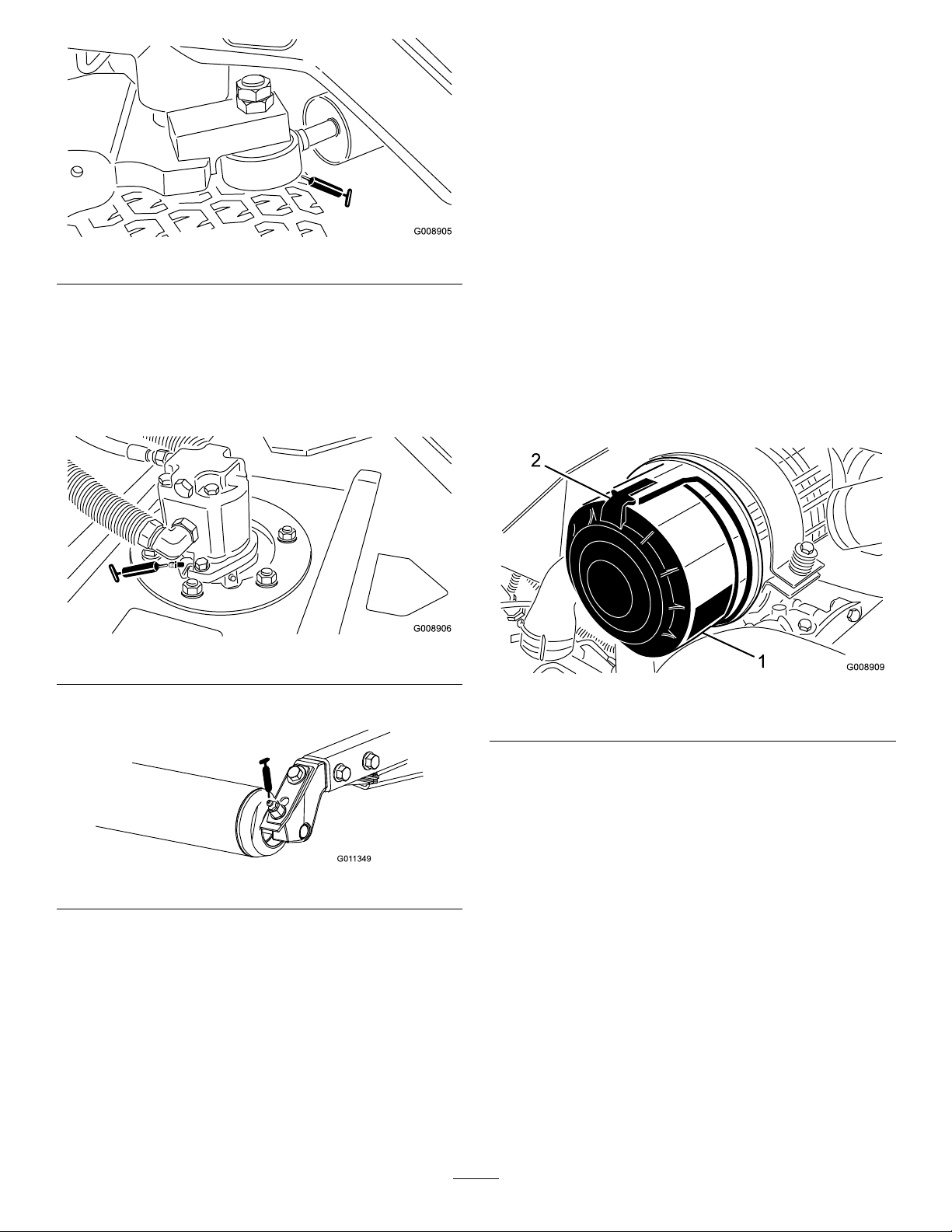
Figure48
G011349
•Cuttingunitspindleshaftbearings(2percuttingunit)
(Figure49)
Note:Eitherttingcanbeused,whicheverismore
accessible.Pumpgreaseintothettinguntilasmall
amountappearsatbottomofthespindlehousing(under
thedeck).
EngineMaintenance
ServicingtheAirCleaner
ServiceInterval:Every200hours(Morefrequentlyin
extremedustyordirtyconditions)
•Checktheaircleanerbodyfordamagewhichcouldcause
anairleak.Replaceifdamaged.Checkthewholeintake
systemforleaks,damage,orloosehoseclamps.
•Serviceattherecommendedserviceintervalorearlierif
engineperformancesuffersduetoextremelydusty,dirty
conditions.Changingtheairlterbeforeitisnecessary
onlyincreasesthechanceofdirtenteringtheenginewhen
thelterisremoved.
•Besurethecoverisseatedcorrectlyandsealswiththe
aircleanerbody.
1.Releasethelatchessecuringtheaircleanercovertothe
aircleanerbody(Figure51).
Figure49
•Rearrollerbearings(2percuttingunit)(Figure50)
Figure50
Note:Makesurethegreasegrooveineachrollermount
alignswiththegreaseholeineachendoftheroller
shaft.Tohelpalignthegrooveandhole,thereisalsoan
alignmentmarkononeendoftherollershaft.
Important:DonotlubricatetheSidewindercross
tube.Thebearingblocksareself-lubricated.
Figure51
1.Aircleanercover2.Aircleanerlatch
2.Removethecoverfromtheaircleanerbody .
3.Beforeremovingthelter,uselowpressureair(40psi,
cleananddry)tohelpremovelargeaccumulationsof
debrispackedbetweenoutsideofprimarylterand
thecanister.Avoidusinghighpressureairwhichcould
forcedirtthroughthelterintotheintaketract.This
cleaningprocesspreventsdebrisfrommigratinginto
theintakewhentheprimarylterisremoved.
4.Removeandreplacetheprimarylter(Figure52).
Cleaningoftheusedelementisnotrecommendeddue
tothepossibilityofdamagetotheltermedia.
44
Page 45

Figure52
Figure53
1.Engineoildrainplug
1.Primarylter
5.Inspectthenewlterforshippingdamage,checking
thesealingendofthelterandthebody.Donotuse
adamagedelement.
6.Insertthenewlterbyapplyingpressuretotheouter
rimoftheelementtoseatitinthecanister.Donot
applypressuretotheexiblecenterofthelter.
7.Cleanthedirtejectionportlocatedintheremovable
cover.Removetherubberoutletvalvefromthecover,
cleanthecavityandreplacetheoutletvalve.
8.Installthecoverorientingtherubberoutletvalveina
downwardposition—betweenapproximately5:00to
7:00whenviewedfromtheend.
9.Securethecoverlatches.
ChangingtheEngineOiland Filter
ServiceInterval:Aftertherst50hours
Every150hours
1.Removeeitherdrainplug(Figure53)andletoilow
intoadrainpan.Whentheoilstopsowing,install
thedrainplug.
2.Removetheoillter(Figure54).Applyalightcoatof
cleanoiltothenewltersealbeforescrewingiton.
Donotovertighten.
Figure54
1.Engineoillter
3.Addoiltothecrankcase;refertoCheckingtheEngine
OilLevel.
45
Page 46

FuelSystem
G009880
1
2
3
Maintenance
ChangingtheFuelFilter Canister
ServiceInterval:Every400hours
ServicingtheFuelTank
ServiceInterval:Every2years—Drainandcleanthefuel
tank.
Drainandcleanthetankifthefuelsystembecomes
contaminatedorifthemachinewillbestoredforanextended
periodoftime.Usecleanfueltoushoutthetank.
InspectingtheFuelLinesand Connections
ServiceInterval:Every400hours/Yearly(whichevercomes
rst)
Inspectthefuellinesandconnectionsfordeterioration,
damage,orlooseconnections.
DrainingtheWaterSeparator
ServiceInterval:Beforeeachuseordaily
1.Placeacleancontainerunderthefuellter.
1.Cleantheareawheretheltercanistermounts(Figure
55).
2.Removetheltercanisterandcleanthemounting
surface.
3.Lubricatethegasketontheltercanisterwithcleanoil.
4.Installtheltercanisterbyhanduntilthegasket
contactsthemountingsurface;thenrotateanadditional
1/2turn.
BleedingAirfromtheInjectors
Note:Thisprocedureshouldbeusedonlyifthefuelsystem
hasbeenpurgedofairthroughnormalprimingprocedures
andtheenginewillnotstart;refertoBleedingtheFuel
System.
1.LoosenthepipeconnectiontotheNo.1nozzleand
holderassembly.
2.Loosenthedrainvalveonthebottomofthelter
canister(Figure55).
Figure55
1.Waterseparator/lter
canister
2.Ventplug
3.Tightenthevalveafterdraining.
3.Drainvalve
Figure56
1.Fuelinjectors
2.MovethethrottletotheFastposition.
3.TurnthekeyinthekeyswitchtotheStartpositionand
watchthefuelowaroundtheconnector.Turnthekey
totheOffpositionwhensolidowisobserved.
4.Tightenthepipeconnectorsecurely.
5.Repeattheprocedureontheremainingnozzles.
46
Page 47

ElectricalSystem
WARNING
Maintenance
CaringfortheBattery
ServiceInterval:Every25hours—Checktheelectrolyte
level.(Ifmachineisinstorage,check
every30days.)
Thebatteryelectrolytelevelmustbeproperlymaintainedand
thetopofthebatterykeptclean.lfthemachineisstoredina
locationwheretemperaturesareextremelyhigh,thebattery
willrundownmorerapidlythanifthemachineisstoredin
alocationwheretemperaturesarecool.
Maintainthecelllevelwithdistilledordemineralizedwater.
Donotllthecellsabovethebottomofthesplitringinside
eachcell.Installthellercapswiththeventspointingtothe
rear(towardthefueltank).
DANGER
Batteryelectrolytecontainssulfuricacidwhichisa
deadlypoisonandcausessevereburns.
•Donotdrinkelectrolyteandavoidcontactwith
skin,eyesorclothing.Wearsafetyglassesto
shieldyoureyesandrubberglovestoprotect
yourhands.
CALIFORNIA
Proposition65Warning
Batteryposts,terminals,andrelated
accessoriescontainleadandleadcompounds,
chemicalsknowntotheStateofCalifornia
tocausecancerandreproductiveharm.
W ash hands after handling .
Fuses
Thefusesinmachineselectricalsystemarelocatedunder
consolecover.
•Fillthebatterywherecleanwaterisalways
availableforushingtheskin.
Keepthetopofthebatterycleanbywashingitperiodically
withabrushdippedinammoniaorbicarbonateofsoda
solution.Flushthetopsurfacewithwateraftercleaning.Do
notremovethellercapswhilecleaning.
Thebatterycablesmustbetightontheterminalstoprovide
goodelectricalcontact.
WARNING
Incorrectbatterycableroutingcoulddamagethe
tractorandcablescausingsparks.Sparkscancause
thebatterygassestoexplode,resultinginpersonal
injury.
•Always
cablebeforedisconnectingthepositive(red)
cable.
•Always
beforeconnectingthenegative(black)cable.
disconnect
connect
thenegative(black)battery
thepositive(red)batterycable
Ifcorrosionoccursattheterminals,disconnectthecables,
negative(–)cablerst,andscrapetheclampsandterminals
separately.Reconnectthecables,positive(+)cablerst,and
coattheterminalswithpetroleumjelly.
47
Page 48
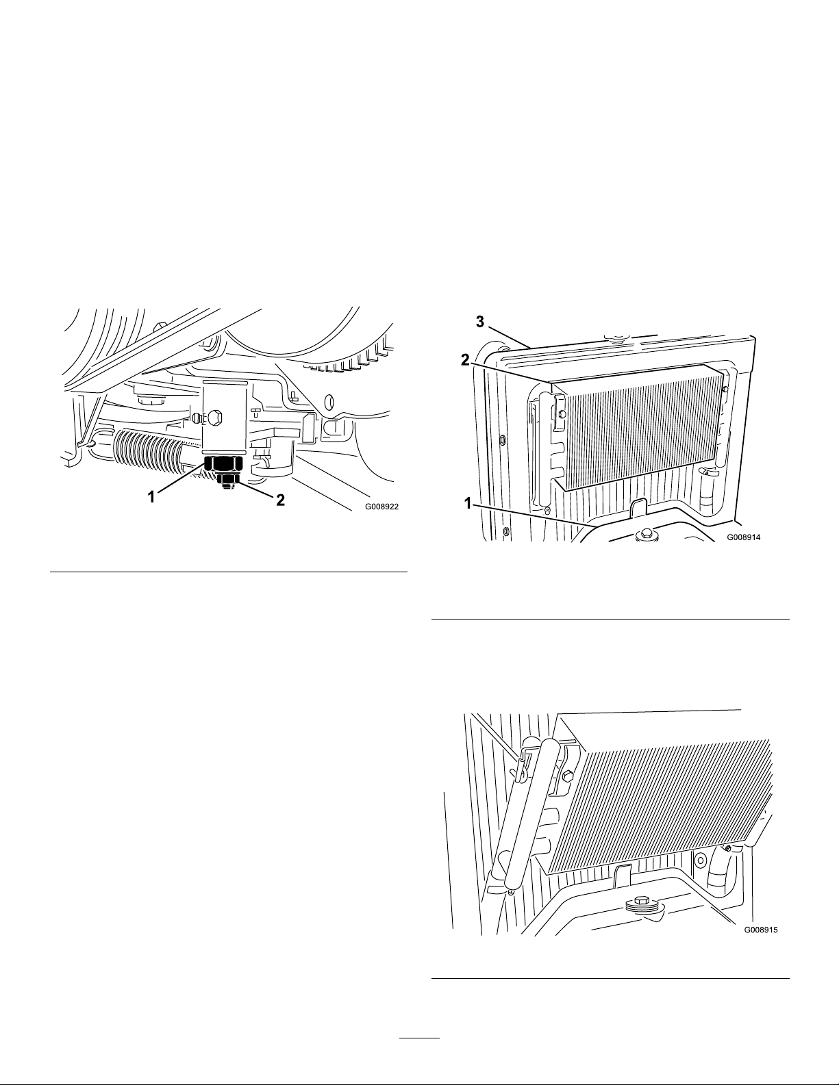
DriveSystem
CoolingSystem
Maintenance
AdjustingtheTractionDrive forNeutral
Ifthemachinemoveswhenthetractionpedalisintheneutral
position,thetractioncammustbeadjusted.
1.Positionthethrottleleverrearwardsoitstopsagainst
thecontrolpanelslot.
2.Loosenthethrottlecableconnectorontheinjection
pumpleverarm(Figure57).
Maintenance
CleaningtheEngineCooling System
ServiceInterval:Beforeeachuseordaily
Removedebrisfromtheoilcoolerandradiatordaily.Clean
themmorefrequentlyindirtyconditions.
1.Turntheengineoffandraisethehood.Cleanthe
engineareathoroughlyofalldebris.
2.Removetheaccesspanel(Figure58).
Figure57
1.Injectionpumpleverarm
3.Holdtheinjectionpumpleverarmagainstthelowidle
stopandtightenthecableconnector.
4.Loosenthescrewssecuringthethrottlecontroltothe
controlpanel.
5.Pushthethrottlecontrolleverallofthewayforward.
6.Slidethestopplateuntilitcontactsthethrottlelever
andtightenthescrewssecuringthethrottlecontrolto
thecontrolpanel.
7.Ifthethrottledoesnotstayinpositionduring
operation,torquethelocknut,usedtosetthefriction
deviceonthethrottlelever,to40to55in-lb(5to6
N-m).Themaximumforcerequiredtooperatethe
throttlelevershouldbe27N-m(20lb).
Figure58
1.Accesspanel3.Radiator
2.Oilcooler
3.Unlatchtheoilcoolerandpivotitrearward(Figure59).
Cleanbothsidesoftheoilcoolerandradiatorarea
thoroughlywithwaterorcompressedair.Pivottheoil
coolerbackintoposition.
4.Installtheaccesspanelandclosethehood.
48
Figure59
Page 49

BrakeMaintenance
BeltMaintenance
AdjustingtheParkingBrake
ServiceInterval:Every200hours—Checktheparkingbrake
adjustment.
1.Loosenthesetscrewsecuringtheknobtotheparking
brakelever(Figure60).
Figure60
1.Parkingbrakelever
2.Knob
3.Setscrew
ServicingtheEngineBelts
ServiceInterval:Aftertherst10hours—Checkthe
conditionandtensionofallbelts.
Every100hours—Checktheconditionandtension
ofallbelts.
TensioningtheAlternator/FanBelt
1.Openthehood.
2.Checkthetensionbydepressingthebeltmidway
betweenthealternatorandcrankshaftpulleyswith30
N-m(22lb)offorce.Thebeltshoulddeect11mm
(7/16inch).
2.Rotatetheknobuntilaforceof41–68N-m(30–40lb)
isrequiredtoactuatethelever.
3.Tightenthesetscrewaftertheadjustmenthasbeen
attained.
Figure61
1.Alternator/fanbelt
3.Ifthedeectionisincorrect,completethefollowing
proceduretotensionthebelt:
A.Loosentheboltsecuringthebracetotheengine
andtheboltsecuringthealternatortothebrace.
B.Insertaprybarbetweenthealternatorandengine
andpryoutonthealternator.
C.Whenthepropertensionisachieved,tighten
thealternatorandbraceboltstosecurethe
adjustment.
ReplacingtheHydrostatDriveBelt
1.Insertanutdriverorsmallpieceoftubingontothe
endofthebelttensioningspring.
WARNING
Usecautionwhende-tensioningthespring,as
itisunderaheavyload.
2.Pushdownandforwardonthespringend(Figure62)
tounhookitfromthebracketandreleasetensionon
thespring.
49
Page 50

Figure62
ControlsSystem
Maintenance
AdjustingtheThrottle
1.Positionthethrottleleverrearwardsoitstopsagainst
thecontrolpanelslot.
2.Loosenthethrottlecableconnectorontheinjection
pumpleverarm(Figure63).
1.Hydrostatdrivebelt
3.Replacethebelt.
4.Reversetheproceduretotensionthespring.
2.Springend
Figure63
1.Injectionpumpleverarm
3.Holdtheinjectionpumpleverarmagainstthelowidle
stopandtightenthecableconnector.
4.Loosenthescrewssecuringthethrottlecontroltothe
controlpanel.
5.Pushthethrottlecontrolleverallofthewayforward.
6.Slidethestopplateuntilitcontactsthethrottlelever
andtightenthescrewssecuringthethrottlecontrolto
thecontrolpanel.
7.Ifthethrottledoesnotstayinpositionduring
operation,torquethelocknut,usedtosetthefriction
deviceonthethrottlelever,to5–6N-m(40–55
inch-lb).Themaximumforcerequiredtooperatethe
throttlelevershouldbe27N-m(20lb).
50
Page 51
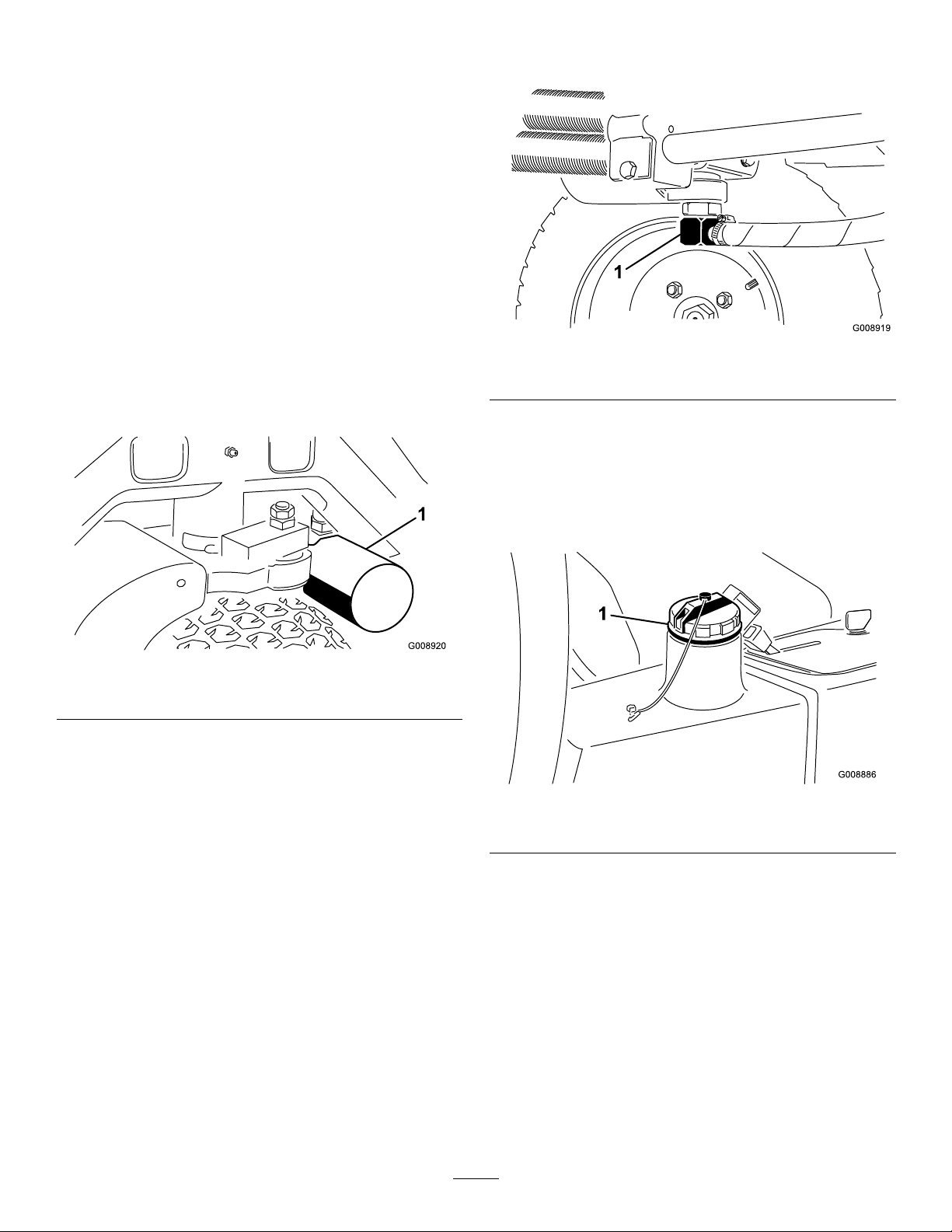
HydraulicSystem
Maintenance
ChangingtheHydraulicFilter
ServiceInterval:Aftertherst10hours
Every200hours/Yearly(whichevercomesrst)
UseagenuineTororeplacementlter,PartNo.86-3010.
Important:Useofanyotherltermayvoidthewarranty
onsomecomponents.
1.Positionthemachineonalevelsurface,lowerthe
cuttingunits,stoptheengine,engagetheparkingbrake,
andremovethekeyfromtheignitionswitch.
2.Pinchoffthehosetotheltermountingplate.
3.Cleanaroundtheltermountingarea.Placeadrain
panunderthelter(Figure64)andremovethelter.
owintoadrainpan.Installthehydrauliclinewhen
hydraulicuidstopsdraining.
Figure65
1.Hydraulicline
3.Fillthereservoir(Figure66)withapproximately13.2
liters(3.5U .S.gallons)ofhydraulicuid;referto
CheckingtheHydraulicSystem.
Important:Useonlythehydraulicuids
specied.Otheruidscouldcausesystem
damage.
Figure64
1.Hydrauliclter
4.Lubricatethenewltergasketandllthelterwith
hydraulicuid.
5.Ensurethattheltermountingareaisclean.Screwthe
lteronuntilthegasketcontactsthemountingplate;
thentightenthelter1/2turn.
6.Releasethehosetotheltermountingplate.
7.Starttheengineandletitrunforabouttwominutesto
purgeairfromthesystem.Stoptheengineandcheck
forleaks.
ChangingtheHydraulicFluid
ServiceInterval:Every400hours
Iftheuidbecomescontaminated,contactyourlocalToro
distributorbecausethesystemmustbeushed.Contaminated
uidlooksmilkyorblackwhencomparedtocleanoil.
1.Turntheengineoffandraisethehood.
2.Disconnectthehydraulicline(Figure65)orremovethe
hydrauliclter(Figure64)andletthehydraulicuid
Figure66
1.Hydraulicllcap
4.Installthereservoircap.Starttheengineanduseallof
thehydrauliccontrolstodistributethehydraulicuid
throughoutthesystem.Alsocheckforleaks;thenstop
theengine.
5.Checktheuidlevelandaddenoughtoraisethelevel
toFullmarkonthedipstick.Donotoverll.
51
Page 52

CheckingtheHydraulicLines andHoses
ServiceInterval:Beforeeachuseordaily
CuttingDeck Maintenance
Checkhydrauliclinesandhosesforleaks,kinkedlines,loose
mountingsupports,wear,loosettings,weatherdeterioration,
andchemicaldeterioration.Makeallnecessaryrepairsbefore
operating.
WARNING
Hydraulicuidescapingunderpressurecan
penetrateskinandcauseinjury.
•Makesureallhydraulicuidhosesandlinesare
ingoodconditionandallhydraulicconnections
andttingsaretightbeforeapplyingpressureto
thehydraulicsystem.
•Keepyourbodyandhandsawayfrompin
holeleaksornozzlesthatejecthighpressure
hydraulicuid.
•Usecardboardorpapertondhydraulicleaks.
•Safelyrelieveallpressureinthehydraulicsystem
beforeperforminganyworkonthehydraulic
system.
•Seekimmediatemedicalattentionifuidis
injectedintoskin.
SeparatingtheCuttingDecks fromtheTractionUnit
1.Positionthemachineonalevelsurface,lowerthe
cuttingdeckstotheoor,shuttheengineoff,and
engagetheparkingbrake.
2.Disconnectandremovethehydraulicmotorfrom
thedeck(Figure67).Coverthetopofthespindleto
preventcontamination.
Figure67
1.Motormountingscrews
3.Removethelynchpinorretainingnutsecuringthe
deckcarrierframetotheliftarmpivotpin(Figure68).
Figure68
1.Lynchpin
4.Rollthecuttingdeckawayfromthetractionunit.
52
2.Liftarmpivotpin
Page 53

MountingtheCuttingDecksto
G011353
6:00
12:00
9:00
3:00
theTractionUnit
1.Positionmachineonalevelsurfaceandshutengineoff.
2.Movecuttingdeckintopositioninfrontoftraction
unit.
3.Slidedeckcarrierframeontoliftarmpivotpin.Secure
withlynchpinorretainingnut(Figure68).
4.Installthehydraulicmotortothedeck(Figure67).
MakesurethattheO-ringisinpositionandnot
damaged.
5.Greasethespindle.
ServicingtheBladePlane
Therotarydeckcomesfromthefactorypresetat5cm(2.00
inch)height-of-cutandbladerakeof7.9mm(0.310inch).
Theleft-handandright-handheightsarealsopresettowithin
±0.7mm(0.030inch)oftheother.
Thecuttingdeckisdesignedtowithstandbladeimpacts
withoutdeformationofthechamber.Ifasolidobjectis
struck,inspectthebladefordamageandthebladeplanefor
accuracy.
6.Comparethe12o’clockmeasuredheighttothe
height-of-cutsetting.Itshouldbewithin0.7mm(0.030
inch).The3and9o’clockheightsshouldbe3.8±2.2
mm(0.150±.090inch)higherthanthe12o’clock
settingandwithin2.2mm(0.090inch)ofeachother.
Ifanyofthesemeasurementsarenotwithinspecication,
proceedtoAdjustingtheBladePlane.
AdjustingtheBladePlane
Startwiththefrontadjustment(changeonebracketatatime).
1.Removetheheight-of-cutbracket,(front,left,orright)
fromthedeckframe(Figure70).
2.Adjust1.5mm(0.060inch)shimsand/or0.7mm
(0.030inch)shimbetweenthedeckframeandbracket
toachievethedesiredheightsetting(Figure70).
InspectingtheBladePlane
1.Removethehydraulicmotorfromthecuttingdeckand
removethecuttingdeckfromthetractor.
2.Useahoist(orminimumoftwopeople)andplacethe
cuttingdeckonaattable
3.Markoneendofthebladewithapaintpenormarker.
Usethisendofthebladetocheckallheights.
4.Positionthecuttingedgeofthemarkedendofthe
bladeat12o’clock(straightaheadinthedirectionof
mowing)(Figure69)andmeasureheightfromtable
tocuttingedgeofblade.
Figure70
1.Heightofcutbracket2.Shims
3.Installtheheight-of-cutbrackettothedeckframewith
theremainingshimsassembledbelowtheheight-of-cut
bracket.
4.Securethesocketheadbolt/spacerandangenut.
Note:Socketheadbolt/spacerareheldtogetherwith
Loctitetopreventthespacerfromfallinginsidethe
deckframe.
5.Verifythe12o’clockheightandadjustifneeded.
6.Determineifonlyoneorboth(right-handand
left-hand)height-of-cutbracketsneedtobeadjusted.
Ifthe3or9o’clocksideis3.8±2.2mm(0.150±0.090
inch)higherthanthenewfrontheightthenno
adjustmentisneededforthatside.Adjusttheother
sidetowithin±2.2mm(0.090inch)ofthecorrectside.
Figure69
5.Rotatethemarkedendofthebladetothe3and9
o’clockpositions(Figure69)andmeasuretheheights.
7.Adjusttherightand/orleftheight-of-cutbracketsby
repeatingsteps1through3.
8.Securethecarriageboltsandangenuts.
9.Again,verifythe12,3,and9o’clockheights.
53
Page 54

ServicingtheCutterBlade
G011355
1
2
RemovingtheCutterBlade
Theblademustbereplacedifasolidobjectishit,theblade
isoutofbalance,orifthebladeisbent.Alwaysusegenuine
Tororeplacementbladestobesureofsafetyandoptimum
performance.Neverusereplacementbladesmadebyother
manufacturersbecausetheycouldbedangerous.
1.Raisethecuttingdecktothehighestposition,shutthe
engineoff,andengagetheparkingbrake.Blockthe
cuttingdecktopreventitfromfallingaccidentally.
2.Grasptheendofthebladeusingaragorthickly
paddedglove.Removethebladebolt,anti-scalpcup,
andbladefromthespindleshaft(Figure71).
machine.Ifwearisnoticed(Figure72),replacethe
blade;refertoRemovingtheCutterBlade.
DANGER
Ifthebladeisallowedtowear,aslotwillform
betweenthesailandatpartoftheblade
(Figure72).Eventuallyapieceoftheblade
maybreakoffandbethrownfromunderthe
housing,possiblyresultinginseriousinjuryto
yourselforbystanders.
•Inspectthebladeperiodicallyforwearor
damage.
•Alwaysreplaceawornordamagedblade.
Figure71
1.Bladebolt2.Anti-scalpcup
3.Installtheblade,sailfacingtowardthecuttingdeck,
withtheanti-scalpcupandbladebolt(Figure71).
Tightenbladeboltto115–149N-m(85–110ft-lb).
DANGER
Awornordamagedbladecanbreak,anda
pieceofthebladecouldbethrownintothe
operator’sorbystander’sarea,resultingin
seriouspersonalinjuryordeath
•Inspectthebladeperiodicallyforwearor
damage.
•Neverweldabrokenorcrackedblade.
•Alwaysreplaceawornordamagedblade.
InspectingandSharpeningtheBlade
1.Raisethecuttingdecktothehighestposition,shutthe
engineoff,andengagetheparkingbrake.Blockthe
cuttingdecktopreventitfromfallingaccidentally.
2.Examinethecuttingendsofthebladecarefully,
especiallywheretheatandcurvedpartsoftheblade
meet(Figure72).Sincesandandabrasivematerialcan
wearawaythemetalthatconnectstheatandcurved
partsoftheblade,checkthebladebeforeusingthe
Figure72
1.Cuttingedge3.Wear/slot/crack
2.Sail
3.Inspectthecuttingedgesofallblades.Sharpenthe
cuttingedgesiftheyaredullornicked.Sharpenonly
thetopofthecuttingedgeandmaintaintheoriginal
cuttingangletomakesureofsharpness(Figure73).
Thebladewillremainbalancedifthesameamountof
metalisremovedfrombothcuttingedges.
Figure73
1.Sharpenatthisangleonly
4.Tocheckthebladeforbeingstraightandparallel,lay
thebladeonalevelsurfaceandcheckitsends.The
endsoftheblademustbeslightlylowerthanthecenter,
andthecuttingedgemustbelowerthantheheelofthe
blade.Thisbladewillproducegoodqualityofcutand
requireminimalpowerfromtheengine.Bycontrasta
bladethatishigherattheendsthanthecenter,orif
cuttingedgeishigherthantheheel,thebladeisbentor
warpedandmustbereplaced.
54
Page 55
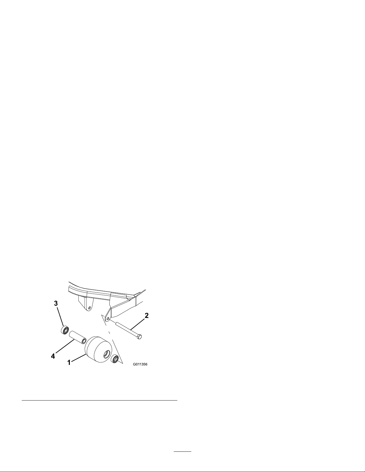
5.Installtheblade,sailfacingtowardcuttingdeck,with
G011356
1
2
3
4
theanti-scalpcupandbladebolt.Tightentheblade
boltto115–149N-m(85–110ft-lb).
CheckingtheBladeStoppingTime
ServiceInterval:Beforeeachuseordaily
Thebladesofthecuttingdeckshouldcometoacomplete
stopinapproximately5secondsafteryoushutdownthe
cuttingdeckengagementswitch.
AssemblingtheFrontRoller
1.Presstherstbearingintotherollerhousing(Figure
74).Pressontheouterraceonlyorequallyonthe
innerandouterrace.
2.Insertthespacer(Figure74).
3.Pressthesecondbearingintotherollerhousing(Figure
74)pressingequallyontheinnerandouterraceuntil
theinnerracecomesincontactwiththespacer.
4.Installtherollerassemblyintothedeckframe.
Note:Makesurethedecksareloweredontoacleansection
ofturforhardsurfacetoavoidthrowndustanddebris.
Toverifythisstoppingtime,haveasecondpersonstandback
fromthedeckatleast6m(20feet)andwatchtheblades
ononeofthecuttingdecks.Havetheoperatorshutthe
cuttingdecksdownandrecordthetimeittakesfortheblades
tocometoacompletestop.Ifthistimeisgreaterthan7
seconds,thebrakingvalveneedsadjustment.CallyourToro
Distributorforassistanceinmakingthisadjustment.
ServicingtheFrontRoller
Inspectthefrontrollerforwear,excesswobble,orbinding.
Serviceorreplacetherollerorcomponentsifanyofthese
conditionsexist.
DisassemblingtheFrontRoller
1.Removetherollermountingbolt(Figure74).
2.Insertapunchthroughtheendoftherollerhousing
anddrivetheoppositebearingoutbyalternatingtaps
totheoppositesideofinnerbearingrace.Thereshould
bea1.5mm(0.060inch)lipofinnerraceexposed.
Important:Securingtherollerassemblywitha
gaplargerthan1.5mm(0.060inch)createsaside
loadonthebearingandcanleadtopremature
bearingfailure
5.Verifythatthereisnomorethana1.5mm(0.060inch)
gapbetweenrollerassemblyandtherollermount
bracketsofthedeckframe.Ifthereisagapover1.5
mm(0.060inch),installenough5/8inchdiameter
washerstotakeuptheslop.
6.Securethemountingboltto108N-m(80ft-lb).
Figure74
1.Frontroller3.Bearing
2.Mountingbolt4.Bearingspacer
3.Pushthesecondbearingoutinpress.
4.Inspecttherollerhousing,bearings,andbearingspacer
fordamage(Figure74).Replacedamagedcomponents
andassemble.
55
Page 56

Storage
StoringtheBattery
Ifthemachinewillbestoredmorethan30days,remove
thebatteryandchargeitfully.Storethebatteryinacool
atmospheretoavoidquickdeteriorationofthechargeinthe
battery.Topreventthebatteryfromfreezing,makesureitis
fullycharged.Thespecicgravityofafullychargedbatteryis
1.265–1.299.
Engine
1.Draintheengineoilfromtheoilpanandreplacethe
drainplug.
2.Removeanddiscardtheoillter.Installanewoillter.
3.Relltheoilpanwithapproximately3.8liters(4quarts)
ofSAE15W-40motoroil.
4.Starttheengineandrunitatidlespeedfor
approximatelytwominutes.
5.Stoptheengine.
PreparationforSeasonal Storage
Followtheseproceduresanytimeyouwillbestoringthe
machineformorethan30days.
TractionUnit
1.Thoroughlycleanthetractionunit,cuttingunits,and
engine.
2.Checkthetirepressure.Inatealltiresto97to110
kPa(14to18psi).
3.Checkallfastenersforlooseness;tightenasnecessary.
4.Greaseoroilallgreasettingsandpivotpoints.Wipe
upanyexcesslubricant.
5.Lightlysandandusetouch-uppaintonpaintedareas
thatarescratched,chipped,orrusted.Repairanydents
inthemetalbody.
6.Servicethebatteryandcablesasfollows:
A.Removethebatteryterminalsfromthebattery
posts.
6.Thoroughlydrainallfuelfromthefueltank,fuellines,
fuellter,andwaterseparatorassembly.
7.Flushthefueltankwithfresh,cleandieselfuel.
8.Secureallfuelsystemttings.
9.Thoroughlycleanandservicetheaircleanerassembly.
10.Sealtheaircleanerinletandtheexhaustoutletwith
weatherprooftape.
11.Checkanti-freezeprotectionandaddasneededfor
expectedminimumtemperatureinyourarea.
CuttingDeck
Ifthecuttingdeckisseparatedfromthetractionunitforany
lengthoftime,installaspindlepluginthetopofthespindle
toprotectthespindlefromdustandwater.
B.Removethebattery.
C.Slowlyrechargethebatterybeforestorageand
every60daysthereafterfor24hourstoprevent
leadsulfationofthebattery.
Topreventthebatteryfromfreezing,makesure
itisfullycharged.Thespecicgravityofafully
chargedbatteryis1.265–1.299.
D.Cleanthebattery,terminals,andpostswithawire
brushandbakingsodasolution.
E.Coatthecableterminalsandbatterypostswith
Grafo112Xskin-overgrease(ToroPartNo.
505-47)orpetroleumjellytopreventcorrosion.
F.Eitherstoreitontheshelforonthemachinein
acoolarea.Leavethecablesdisconnectedifitis
storedonthemachine.
56
Page 57

Notes:
57
Page 58

Notes:
58
Page 59

Notes:
59
Page 60

TheToroTotalCoverageGuarantee
ALimitedWarranty
ConditionsandProductsCovered
TheToroCompanyanditsafliate,T oroWarrantyCompany,pursuant
toanagreementbetweenthem,jointlywarrantyourT oroCommercial
product(“Product”)tobefreefromdefectsinmaterialsorworkmanship
fortwoyearsor1500operationalhours*,whicheveroccursrst.This
warrantyisapplicabletoallproductswiththeexceptionofAerators
(refertoseparatewarrantystatementsfortheseproducts).Wherea
warrantableconditionexists,wewillrepairtheProductatnocosttoyou
includingdiagnostics,labor,parts,andtransportation.Thiswarranty
beginsonthedatetheProductisdeliveredtotheoriginalretailpurchaser.
*Productequippedwithanhourmeter.
InstructionsforObtainingWarrantyService
YouareresponsiblefornotifyingtheCommercialProductsDistributoror
AuthorizedCommercialProductsDealerfromwhomyoupurchasedthe
Productassoonasyoubelieveawarrantableconditionexists.Ifyouneed
helplocatingaCommercialProductsDistributororAuthorizedDealer,or
ifyouhavequestionsregardingyourwarrantyrightsorresponsibilities,
youmaycontactusat:
ToroCommercialProductsServiceDepartment
ToroWarrantyCompany
811 1LyndaleAvenueSouth
Bloomington,MN55420-1196
952–888–8801or800–952–2740
E-mail:commercial.warranty@toro.com
OwnerResponsibilities
AstheProductowner,youareresponsibleforrequiredmaintenanceand
adjustmentsstatedinyourOperator'sManual.Failuretoperformrequired
maintenanceandadjustmentscanbegroundsfordisallowingawarranty
claim.
ItemsandConditionsNotCovered
Notallproductfailuresormalfunctionsthatoccurduringthewarranty
periodaredefectsinmaterialsorworkmanship.Thiswarrantydoesnot
coverthefollowing:
•Productfailureswhichresultfromtheuseofnon-T ororeplacement
parts,orfrominstallationanduseofadd-on,ormodiednon-Toro
brandedaccessoriesandproducts.Aseparatewarrantymaybe
providedbythemanufactureroftheseitems.
•Productfailureswhichresultfromfailuretoperformrecommended
maintenanceand/oradjustments.Failuretoproperlymaintainyour
ToroproductpertheRecommendedMaintenancelistedinthe
Operator’sManualcanresultinclaimsforwarrantybeingdenied.
•ProductfailureswhichresultfromoperatingtheProductinanabusive,
negligent,orrecklessmanner.
•Partssubjecttoconsumptionthroughuseunlessfoundtobedefective.
Examplesofpartswhichareconsumed,orusedup,duringnormal
Productoperationinclude,butarenotlimitedto,brakepadsand
linings,clutchlinings,blades,reels,rollersandbearings(sealedor
greasable),bedknives,sparkplugs,castorwheelsandbearings,tires,
lters,belts,andcertainsprayercomponentssuchasdiaphragms,
nozzles,andcheckvalves,etc.
•Failurescausedbyoutsideinuence.Conditionsconsideredtobe
outsideinuenceinclude,butarenotlimitedto,weather,storage
practices,contamination,useofunapprovedfuels,coolants,lubricants,
additives,fertilizers,water,orchemicals,etc.
•Failureorperformanceissuesduetotheuseoffuels(e.g.gasoline,
diesel,orbiodiesel)thatdonotconformtotheirrespectiveindustry
standards.
•Normalnoise,vibration,wearandtear ,anddeterioration.
•Normal“wearandtear”includes,butisnotlimitedto,damagetoseats
duetowearorabrasion,wornpaintedsurfaces,scratcheddecalsor
windows,etc.
Parts
Partsscheduledforreplacementasrequiredmaintenancearewarranted
fortheperiodoftimeuptothescheduledreplacementtimeforthatpart.
Partsreplacedunderthiswarrantyarecoveredforthedurationofthe
originalproductwarrantyandbecomethepropertyofT oro.T orowillmake
thenaldecisionwhethertorepairanyexistingpartorassemblyorreplace
it.T oromayuseremanufacturedpartsforwarrantyrepairs.
DeepCycleandLithium-IonBatteryWarranty:
DeepcycleandLithium-Ionbatterieshaveaspeciedtotalnumberof
kilowatt-hourstheycandeliverduringtheirlifetime.Operating,recharging,
andmaintenancetechniquescanextendorreducetotalbatterylife.Asthe
batteriesinthisproductareconsumed,theamountofusefulworkbetween
chargingintervalswillslowlydecreaseuntilthebatteryiscompletelyworn
out.Replacementofwornoutbatteries,duetonormalconsumption,
istheresponsibilityoftheproductowner.Batteryreplacementmaybe
requiredduringthenormalproductwarrantyperiodatowner’sexpense.
Note:(Lithium-Ionbatteryonly):ALithium-Ionbatteryhasapartonly
proratedwarrantybeginningyear3throughyear5basedonthetime
inserviceandkilowatthoursused.RefertotheOperator'sManualfor
additionalinformation.
MaintenanceisatOwner’sExpense
Enginetune-up,lubrication,cleaningandpolishing,replacementoflters,
coolant,andcompletingrecommendedmaintenancearesomeofthe
normalservicesT oroproductsrequirethatareattheowner’sexpense.
GeneralConditions
RepairbyanAuthorizedToroDistributororDealerisyoursoleremedy
underthiswarranty.
NeitherTheToroCompanynorToroWarrantyCompanyisliablefor
indirect,incidentalorconsequentialdamagesinconnectionwiththe
useoftheToroProductscoveredbythiswarranty,includingany
costorexpenseofprovidingsubstituteequipmentorserviceduring
reasonableperiodsofmalfunctionornon-usependingcompletion
ofrepairsunderthiswarranty.ExceptfortheEmissionswarranty
referencedbelow,ifapplicable,thereisnootherexpresswarranty.All
impliedwarrantiesofmerchantabilityandtnessforusearelimitedto
thedurationofthisexpresswarranty.
Somestatesdonotallowexclusionsofincidentalorconsequential
damages,orlimitationsonhowlonganimpliedwarrantylasts,sotheabove
exclusionsandlimitationsmaynotapplytoyou.Thiswarrantygivesyou
speciclegalrights,andyoumayalsohaveotherrightswhichvaryfrom
statetostate.
Noteregardingenginewarranty:
TheEmissionsControlSystemonyourProductmaybecoveredby
aseparatewarrantymeetingrequirementsestablishedbytheU.S.
EnvironmentalProtectionAgency(EP A)and/ortheCaliforniaAirResources
Board(CARB).Thehourlimitationssetforthabovedonotapplytothe
EmissionsControlSystemWarranty.RefertotheEngineEmissionControl
WarrantyStatementsuppliedwithyourproductorcontainedintheengine
manufacturer’sdocumentationfordetails
CountriesOtherthantheUnitedStatesorCanada
CustomerswhohavepurchasedT oroproductsexportedfromtheUnitedStatesorCanadashouldcontacttheirT oroDistributor(Dealer)toobtain
guaranteepoliciesforyourcountry ,province,orstate.IfforanyreasonyouaredissatisedwithyourDistributor'sserviceorhavedifcultyobtaining
guaranteeinformation,contacttheT oroimporter.
374-0253RevB
 Loading...