

Toro 30834, groundsmaster 4500-D, groundsmaster 3500-G, groundsmaster 3500-D, groundsmaster 4700-D Operator's Manual
Page 1
27inRotaryCuttingUnit
FormNo.3363-477RevB
Groundsmaster
®
3500-D/3500-G/3505-D/4500-D/4700-D
ModelNo.30834—SerialNo.310000001andUp
ToregisteryourproductordownloadanOperator'sManualorPartsCatalogatnocharge,gotowww.T oro.com.OriginalInstructions(EN)
Page 2

ThisproductcomplieswithallrelevantEuropean
directives,fordetailspleaseseetheseparateproduct
specicDeclarationofConformity(DOC)sheet.
Introduction
Thisrotary-bladelawncuttingdeckismounted
toaride-onmachineandisintendedtobeused
byprofessional,hiredoperatorsincommercial
applications.Itisprimarilydesignedforcuttinggrass
onwell-maintainedlawnsinparks,sportselds,and
oncommercialgrounds.Itisnotdesignedforcutting
brush,mowinggrassandothergrowthalongside
highways,orforagriculturaluses.
Readthisinformationcarefullytolearnhowtooperate
andmaintainyourproductproperlyandtoavoidinjury
andproductdamage.Youareresponsibleforoperating
theproductproperlyandsafely.
YoumaycontactTorodirectlyatwww .Toro.comfor
productandaccessoryinformation,helpndingadealer,
ortoregisteryourproduct.
Wheneveryouneedservice,genuineToroparts,or
additionalinformation,contactanAuthorizedService
DealerorToroCustomerServiceandhavethemodel
andserialnumbersofyourproductready .Themodel
andserialnumbersarestampedonaplateontherearof
thecuttingunit,underthecover.Writethenumbersin
thespaceprovided.
ModelNo.
Contents
Introduction.................................................................2
Safety...........................................................................3
SafetyandInstructionalDecals.............................3
Setup...........................................................................4
AdjustingtheCarrierFrame(Groundsmaster
3500-Dand3500-Gonly).................................4
AdjustingtheHeight-of-Cut.................................4
AdjustingtheRollerScraper(Optional).................5
InstallingtheMulchingBafe(Optional)...............5
ProductOverview........................................................6
Specications.......................................................6
DimensionsandWeights(approx.)........................6
Attachments/Accessories.....................................6
Operation.....................................................................6
SelectingaBlade...................................................6
OperatingTips.....................................................7
Maintenance.................................................................9
RecommendedMaintenanceSchedule(s)..................9
UsingtheCuttingDeckServiceLatch
(Groundsmaster3500-Dand3500-G
only).................................................................9
GreasingtheBearings...........................................9
SeparatingtheCuttingDecksfromthe
TractionUnit..................................................10
MountingtheCuttingDeckstotheTraction
Unit................................................................10
ServicingtheBladePlane....................................10
RemovingtheCutterBlade.................................11
InspectingandSharpeningtheBlade...................12
CheckingtheBladeStoppingTime......................13
ServicingtheFrontRoller...................................13
Storage.......................................................................14
SerialNo.
Thismanualidentiespotentialhazardsandhassafety
messagesidentiedbythesafetyalertsymbol(Figure1),
whichsignalsahazardthatmaycauseseriousinjury
ordeathifyoudonotfollowtherecommended
precautions.
Figure1
1.Safetyalertsymbol
Thismanualuses2otherwordstohighlightinformation.
Importantcallsattentiontospecialmechanical
informationandNoteemphasizesgeneralinformation
worthyofspecialattention.
©2013—TheT oro®Company
8111LyndaleAvenueSouth
Bloomington,MN55420
Contactusatwww.Toro.com.
2
PrintedintheUSA.
AllRightsReserved
Page 3
Safety
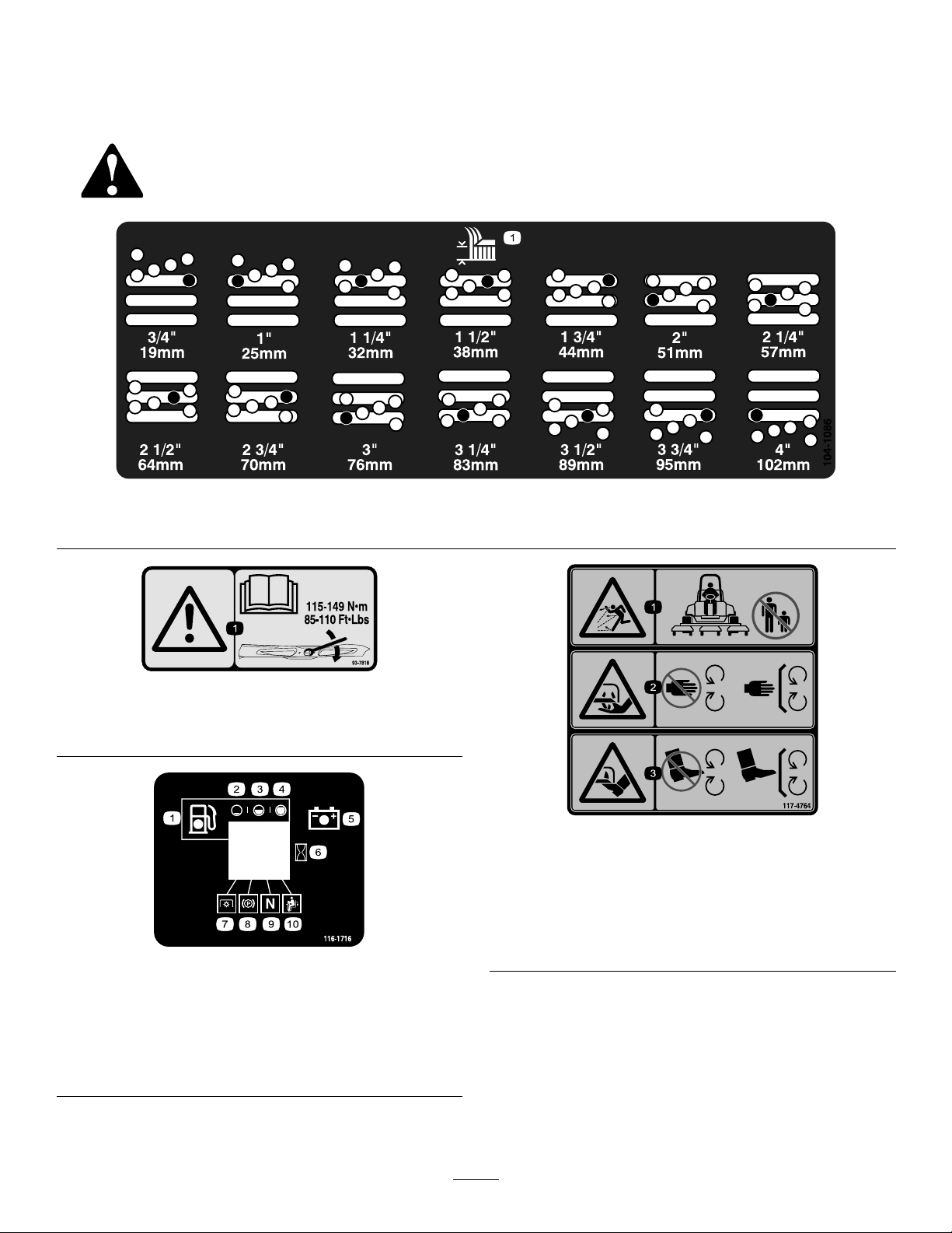
SafetyandInstructionalDecals
Safetydecalsandinstructionsareeasilyvisibletotheoperatorandarelocatednearanyareaof
potentialdanger.Replaceanydecalthatisdamagedorlost.
104-1086
1.Heightofcut
93-7818
1.Warning—readtheOperator'sManualforinstructionson
torquingthebladebolt/nutto115-149N-m(85-110ft-lb).
116-1716
117-4764
1.Thrownobjecthazard—keepbystandersasafedistance
fromthemachine.
2.Cuttinghazardofhand,mowerblade—stayawayfrom
movingparts,keepallguardsandshieldsinplace.
3.Cuttinghazardoffoot,mowerblade—stayawayfrom
movingparts,keepallguardsandshieldsinplace.
1.Fuel6.Hourmeter
2.Empty
3.Half
4.Full9.Neutral
5.Battery
7.PTO
8.Parkingbrake
10.Operatorpresenceswitch
3
Page 4
Setup
MediaandAdditionalParts
Description
CEDecal
Operator'sManual
PartsCatalog
AdjustingtheCarrierFrame
(Groundsmaster3500-Dand
3500-Gonly)
AdjustingtheFrontCuttingDecks
Thefrontandrearcuttingdecksrequiredifferent
mountingpositions.Thefrontcuttingdeckhastwo
mountingpositionsdependingonwhatheight-of-cut
anddegreeofdeckrotationyoudesire.
1.Forheightsofcutinthe3/4to3inch(2to7.6cm)
range,mountthefrontcarrierframesinthelower
frontmountingholes(
Note:Thispermitsmoreuptravelofthecutting
decksrelativetotractorwhenapproachingquick
uphillchangesinterrain.Itdoeshoweverlimitthe
clearanceofthechambertothecarrierwhencresting
sharpknolls.
Figure2).
Qty.
1
1
1Usetolookupparts.
ApplytothecuttingdeckforCEcompliance.
Readbeforeoperating.
AdjustingtheRearCuttingDeck
Thefrontandrearcuttingdecksrequiredifferent
mountingpositions.Therearcuttingdeckhasone
mountingpositionforproperalignmentwiththe
sidewinderunderframe.
Forallheightsofcut,mounttherearcuttingdeckinthe
rearmountingholes(Figure2).
AdjustingtheHeight-of-Cut
Important:Thiscuttingdeckoftencuts
approximately1/4inch(6mm)lowerthanareel
cuttingunitwiththesamebenchsetting.Itmaybe
necessarytohavetheserotarycuttingdeck’sbench
set1/4inch(6mm)abovethatofreelscuttingin
thesamearea.
Use
Note:Thisincreasesthechambertocarrier
clearanceduetothehigherpositionofthecutting
chamber,butwillcausethecuttingdecktoreach
theirmaximumuptravelsooner.
Figure2
1.Frontdeckmountinghole
(upper)
2.Frontdeckmountinghole
(lower)
2.Forheightsofcutinthe2-1/2to4inch(6.3to10
cm)range,mountthefrontcarrierframesinthe
upperfrontmountingholes(Figure2).
3.Reardeckmountinghole
Important:Accesstotherearcuttingunitsis
greatlyimprovedbyremovingthecuttingunit
fromthetractor.Iftheunitisequippedwitha
Sidewinder®,sidewindthecuttingunitstothe
right,removetherearcuttingunit,andslideitout
totherightside.
1.Lowerthecuttingdecktotheground,stopthe
engine,andremovethekeyfromignitionswitch.
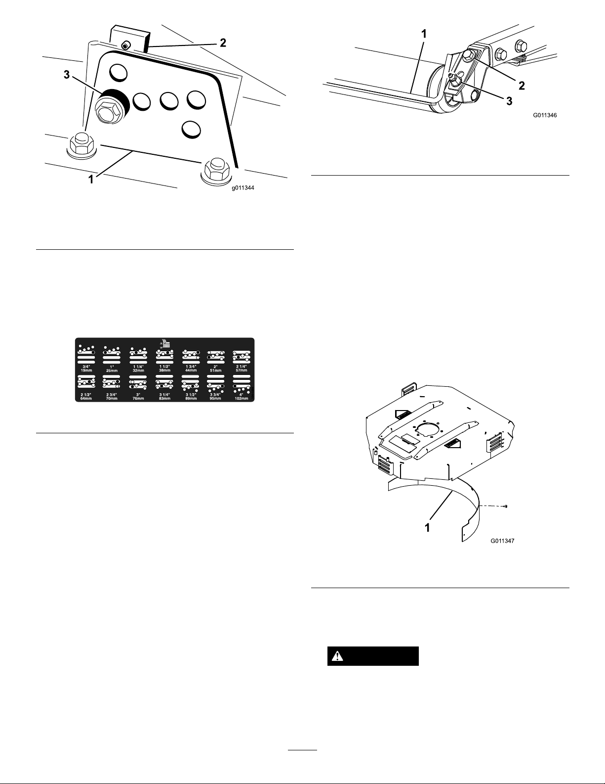
2.Loosentheboltsecuringeachheight-of-cutbracket
totheheight-of-cutplate(frontandeachside)
Figure3).
(
3.Beginningwithfrontadjustment,removethebolt.
4
Page 5
G011346
1
2
3
Figure5
G011347
1
Figure3
1.Heightofcutbracket3.Spacer
2.Heightofcutplate
4.Whilesupportingthechamber,removethespacer
Figure3).
(
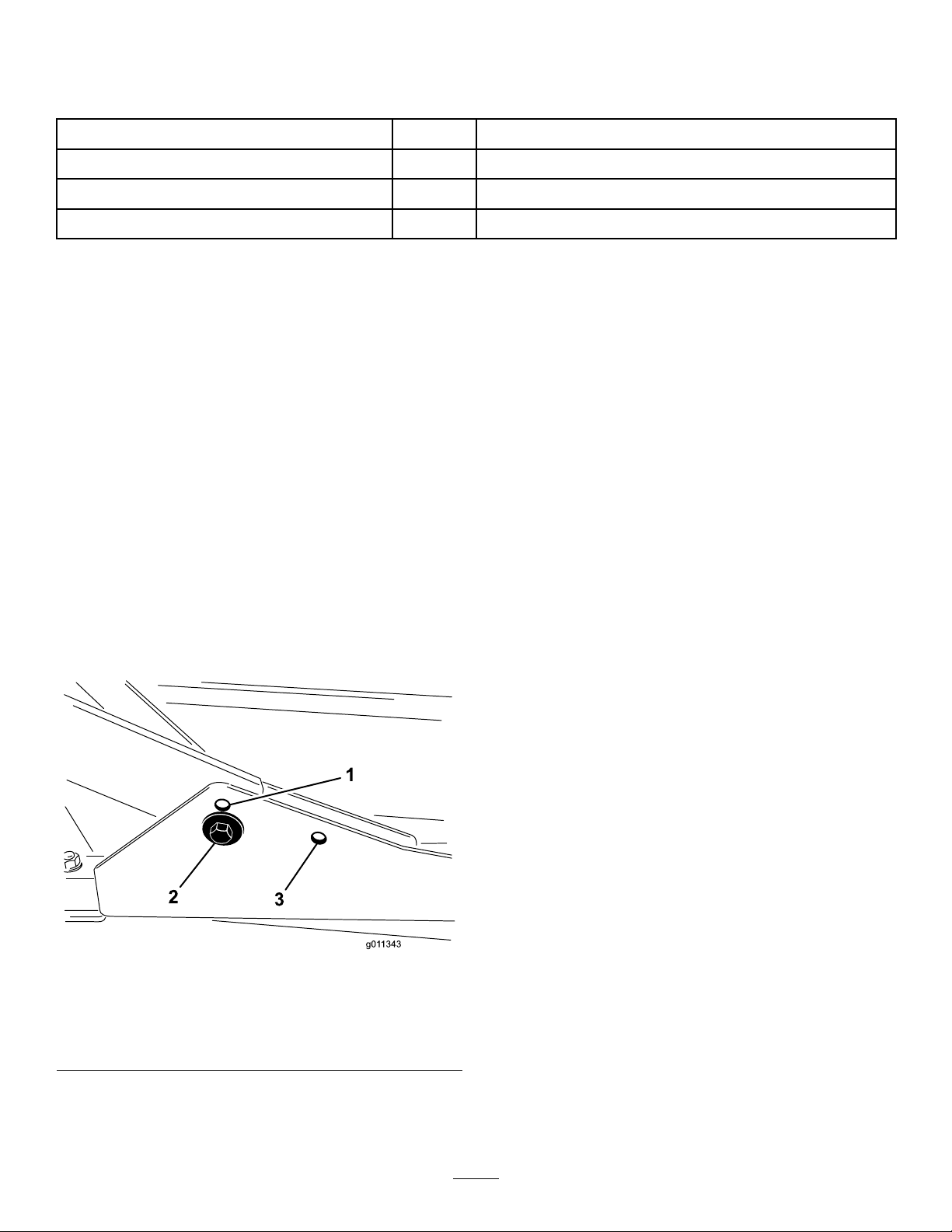
5.Movethechambertothedesiredheight-of-cutand
installaspacerintothedesignatedheight-of-cuthole
andslot(Figure4).
Figure4
1.Rollerspacer
2.Mountingscrew
3.Greasetting
2.Slidethescraperupordownuntilagapof0.020to
0.040inch(0.5to1mm)isachievedbetweenthe
rodandtheroller.
3.Securethegreasettingandscrewto30ft-lb(41
N-m)inanalternatingsequence.
InstallingtheMulchingBafe
(Optional)
1.Thoroughlycleandebrisfromthemountingholes
ontherearwallandleftsidewallofthechamber.
2.Installthemulchingbafeintherearopeningand
secureitwith5angeheadbolts(Figure6).
6.Positionthetappedplateinlinewiththespacer.
7.Installtheboltngertight.
8.Repeatsteps4–7foreachsideadjustment.
9.Tightenallthreeboltsto30ft-lb(41N-m).Always
tightenthefrontboltrst.
Note:Adjustmentsofmorethan1-1/2inches
(3.8cm)mayrequiretemporaryassemblytoan
intermediateheighttopreventbinding(e.g.changing
from1.25to2.75inch(3.1to7cm)height-of-cut).
AdjustingtheRollerScraper
(Optional)
Theoptionalrearrollerscraperisdesignedtoworkbest
whenthereisanevengapof0.020–0.040inch(0.5to1
mm)betweenthescraperandroller.
1.Loosenthegreasettingandmountingscrew
(
Figure5).
Figure6
1.Mulchingbafe
3.Verifythatmulchingbafedoesnotinterferewith
thetipofthebladeanddoesnotprotrudeinsidethe
surfaceoftherearchamberwall.
WARNING
Donotusethehighliftbladewiththemulching
bafe.Thebladecouldbreak,resultingin
personalinjuryordeath.
5
Page 6

ProductOverview
Operation
Specications
Note:Specicationsanddesignaresubjecttochange
withoutnotice.
DimensionsandWeights(approx.)
Length
Width
Height
Weight
Attachments/Accessories
AselectionofToroapprovedattachmentsand
accessoriesareavailableforusewiththemachineto
enhanceandexpanditscapabilities.Contactyour
AuthorizedServiceDealerorDistributororgoto
www.Toro.comforalistofallapprovedattachments
andaccessories.
34inches(86.4cm)
34inches(86.4cm)
9.6inches(24.4cm)tocarriermount
10–1/2inches(26.7cm)at3/4inchheightofcut
13–3/4inches(34.9cm)at4inchheightofcut
195pounds(88kg)
Note:Determinetheleftandrightsidesofthe
machinefromthenormaloperatingposition.
SelectingaBlade
StandardCombinationSail
Thisbladewasdesignedtoprovideexcellentliftand
dispersioninalmostanycondition.Ifmoreorlesslift
anddischargevelocityisrequired,consideradifferent
blade.
Attributes:Excellentliftanddispersioninmost
conditions.
AngledSail
Thebladegenerallyperformsbestinlowerheightsof
cut—3/4to2–1/2inch(1.9to6.4cm).
Attributes:
•Dischargeremainsmoreevenatlowerheightsof
cut.
•Dischargehaslesstendencytothrowleftandthusa
cleanerlookaroundbunkersandfairways.
•Lowerpowerrequirementatlowerheightsand
denseturf.
HighLiftParallelSail
Thebladegenerallyperformsbetterinthehigher
heightsofcut—2to4inch(7to10cm).
Attributes:
•Moreliftandhigherdischargevelocity.
•Sparseorlimpturfispickedupsignicantlyat
higherheightsofcut.
•Wetorstickyclippingsaredischargedmore
efcientlyreducingcongestioninthedeck.
•Requiresmorehorsepowertorun.
•Tendstodischargefurtherleftandcantendto
windrowatlowerheightsofcut.
WARNING
Donotusethehighliftbladewiththemulching
bafe.Thebladecouldbreak,resultinginpersonal
injuryordeath.
6
Page 7

AtomicBlade
Thisbladewasdesignedtoprovideexcellentleaf
mulching.
Attributes:Excellentleafmulching
OperatingTips
MowwhentheGrassisDry
Moweitherinthelatemorningtoavoidthedew,which
causesgrassclumping,orinlateafternoontoavoidthe
damagethatcanbecausedbydirectsunlightonthe
sensitive,freshlymowedgrass.
SelecttheProperHeight-of-CutSetting
toSuitConditions
Removeapproximatelyoneinchornomorethan1/3of
thegrassbladewhencutting.Inexceptionallylushand
densegrassyoumayhavetoraiseyourheight–of–cut
settinganothernotch.
AlwaysStartMowingwithSharp
Blades
Asharpbladecutscleanlyandwithouttearingor
shreddingthegrassbladeslikeadullblade.Tearing
andshreddingcausesthegrasstoturnbrownatthe
edgeswhichimpairsgrowthandincreasessusceptibility
todiseases.Makesurebladeisingoodconditionand
afullsailispresent.
CheckConditionofDeck
Makesurethatthecuttingchambersareingood
condition.Straightenanybendsinthechamber
componentstoensurethecorrectbladetip/chamber
clearance.
AfterOperating
Toensureoptimumperformance,cleantheunderside
ofmowerhousing.Ifyouallowresiduetobuildupin
mowerhousing,cuttingperformancewilldecrease.
7
Page 8

ChoosingAccessories
AngleSailBladeHighLiftParallel
GrassCutting:0.75to
1.75inch(1.9to4.4cm)
Height-of-Cut
GrassCutting:2.00to
2.50inch(5to6.4cm)
Height-of-Cut
GrassCutting:2.75to
4.00inch(7to10cm)
Height-of-Cut
LeafMulchingRecommendedforuse
ProsEvendischargeat
ConsDoesnotliftthegrass
Recommendedinmost
applications
Recommendedforthick
orlushturf
Mayworkwellinlushturf
withthemulchingbafe
lowerheightofcut
Cleanerlookaround
bunkersandfairways
Lowerpower
requirements
wellinhighheight
ofcutapplications
Wetorstickygrass
hasatendencytobuild
upinthechamber,
leadingtopoorquality
ofcutandhigherpower
requirement
OptionalEquipmentConguration
SailBlade
Donotusewiththe
mulchingbafe
Mayworkwellinlightor
sparseturf
Recommendedforlight
orsparseturf
Recommendedinmost
applications
NotAllowedUsewithcombinationsail
Moreliftandhigher
dischargevelocity
Sparseorlimpturf
ispickedupat
highheightofcut
Wetorstickyclippings
aredischargedefciently
Requiresmorepowerto
runinsomeapplications
Tendstowindrowatlower
heightofcutinlushgrass
Donotusewiththe
mulchingbafe
MulchingBafeRollerScraper
Hasbeenshownto
improvedispersionand
aftercutperformance
onnortherngrassesthat
arecutatleastthree
timesperweekandless
than1/3ofthegrass
bladeisremoved.
Donotusewiththe
highliftparallelsail
blade
oranglesailbladeonly
Mayimprovedispersion
andappearancein
certaingrasscutting
applicationsVerygood
forleafmulching
Grasswillbuildupinthe
chamberifattemptingto
removetoomuchgrass
withbafeinplace
Canbeusedanytime
thatrollersbuildup
withgrassorlargeat
grassclumpsofgrass
areseen.Thescrapers
mayactuallyincrease
clumpingincertain
applications.
Reducesrollerbuildupin
certainapplications
8
Page 9

Maintenance
Note:Determinetheleftandrightsidesofthemachinefromthenormaloperatingposition.
RecommendedMaintenanceSchedule(s)
MaintenanceService
Interval
Beforeeachuseordaily
Every50hours
MaintenanceProcedure
•Checkthebladestoppingtime.
•Greasethebearings
CAUTION
Ifyouleavethekeyintheignitionswitch,someonecouldaccidentlystarttheengineandseriouslyinjure
youorotherbystanders.
Removethekeyfromtheignitionanddisconnectthewirefromthesparkplugbeforeyoudoany
maintenance.Setthewireasidesothatitdoesnotaccidentallycontactthesparkplug.
UsingtheCuttingDeckService
Latch(Groundsmaster3500-D
8.Turnoffthemachineandremovethekey.
9.Reversethisproceduretounlatchthecuttingdecks.
and3500-Gonly)
GreasingtheBearings
Whenservicingthecuttingdecks,usetheservicelatch
topreventinjury.
1.Centerthecuttingdecksidewinderwiththetraction
unit.
2.Raisethecuttingdeckstothetransportposition.
3.Settheparkingbrakeandturnoffthemachine.
4.Releasethelatchrod(Figure7)fromfrontcarrier
frameretainer.
ServiceInterval:Every50hours
Eachcuttingdeckhastwogreasettingsperspindle.
Eitherttingcanbeused,whicheverismoreaccessible.
Ifthemachineisoperatedundernormalconditions,
lubricatebladespindlebearings(
generalpurposelithiumbasegreaseormolybdenum
basegrease,afterevery50hoursofoperation.Pump
greaseintothettinguntilasmallamountappearsat
bottomofthespindlehousing(underthedeck).
Figure8)withNo.2
Figure7
1.Servicelatchhook
5.Lifttheoutsideofthefrontcuttingdecksandplace
thelatchovertheframepinmountedonthefrontof
theoperator'splatform(Figure7).
6.Sitontheoperatorseatandstartthetractionunit.
7.Lowerthecuttingdeckstothemowposition.
Figure8
Eachcuttingdeckhastwogreasettingsperrearroller.
Ifthemachineisoperatedundernormalconditions,
lubricaterearrollerbearings(
generalpurposelithiumbasegreaseormolybdenum
basegrease,afterevery50hoursofoperation.
9
Figure9)withNo.2
Page 10

G011349
Figure9
Important:Makesurethegreasegrooveineach
rollermountalignswiththegreaseholeineach
endoftherollershaft.T ohelpalignthegrooveand
hole,thereisalsoanalignmentmarkononeend
oftherollershaft.
1.Lynchpin
Figure11
2.Liftarmpivotpin
SeparatingtheCuttingDecks
fromtheTractionUnit
1.Positionthemachineonalevelsurface,lowerthe
cuttingdeckstotheoor,shuttheengineoff,and
engagetheparkingbrake.
2.Disconnectandremovethehydraulicmotorfrom
thedeck(
preventcontamination.
1.Motormountingscrews
3.Removethelynchpinorretainingnut(GM4700
only)securingthedeckcarrierframetotheliftarm
pivotpin(Figure11).
Figure10).Coverthetopofthespindleto
Figure10
4.Rollthecuttingdeckawayfromthetractionunit.
MountingtheCuttingDecksto
theTractionUnit
1.Positionmachineonalevelsurfaceandshutengine
off.
2.Movecuttingdeckintopositioninfrontoftraction
unit.
3.Slidedeckcarrierframeontoliftarmpivotpin.
Securewithlynchpinorretainingnut(GM4700
only)(
4.Installthehydraulicmotortothedeck(
MakesurethattheO-ringisinpositionandnot
damaged.
5.Greasethespindle.
Figure11).
Figure10).
ServicingtheBladePlane
Therotarydeckcomesfromthefactorypresetat2.00
inch(5cm)height-of-cutandbladerakeof0.310inch
(7.9mm).Theleft-handandright-handheightsarealso
presettowithin±0.030inch(0.7mm)oftheother.
Thecuttingdeckisdesignedtowithstandbladeimpacts
withoutdeformationofthechamber.Ifasolidobject
isstruck,inspectthebladefordamageandtheblade
planeforaccuracy.
InspectingtheBladePlane
1.Removethehydraulicmotorfromthecuttingdeck
andremovethecuttingdeckfromthetractor.
2.Useahoist(orminimumoftwopeople)andplace
thecuttingdeckonaattable.
3.Markoneendofthebladewithapaintpenor
marker.Usethisendofthebladetocheckallheights.
10
Page 11

4.Positionthecuttingedgeofthemarkedendofthe
G011353
6:00
12:00
9:00
3:00
bladeat12o’clock(straightaheadinthedirectionof
mowing)(Figure12)andmeasureheightfromtable
tocuttingedgeofblade.
Figure12
5.Rotatethemarkedendofthebladetothe3and
9o’clockpositions(Figure12)andmeasurethe
heights.
6.Comparethe12o’clockmeasuredheighttothe
height-of-cutsetting.Itshouldbewithin0.030inch
(0.7mm).The3and9o’clockheightsshouldbe
0.150±.090inch(3.8±2.2mm)higherthanthe12
o’clocksettingandwithin0.090inch(2.2mm)of
eachother.
Ifanyofthesemeasurementsarenotwithinspecication,
proceedtoAdjustingtheBladePlane.
AdjustingtheBladePlane
Startwiththefrontadjustment(changeonebracketata
time).
1.Removetheheight-of-cutbracket,(front,left,or
right)fromthedeckframe(Figure13).
Figure13
1.Heightofcutbracket2.Shims
3.Installtheheight-of-cutbrackettothedeckframe
withtheremainingshimsassembledbelowthe
height-of-cutbracket.
4.Securethesocketheadbolt/spacerandangenut.
Note:Socketheadbolt/spacerareheldtogether
withLoctitetopreventthespacerfromfallinginside
thedeckframe.
5.Verifythe12o’clockheightandadjustifneeded.
6.Determineifonlyoneorboth(right-handand
left-hand)height-of-cutbracketsneedtobeadjusted.
Ifthe3or9o’clocksideis0.150±0.090inch
(3.8±2.2mm)higherthanthenewfrontheightthen
noadjustmentisneededforthatside.Adjustthe
othersidetowithin±0.090inch(2.2mm)ofthe
correctside.
7.Adjusttherightand/orleftheight-of-cutbracketsby
repeatingsteps1through3.
8.Securethecarriageboltsandangenuts.
9.Again,verifythe12,3,and9o’clockheights.
2.Adjust0.060inch(1.5mm)shimsand/or0.030inch
(0.7mm)shimbetweenthedeckframeandbracket
toachievethedesiredheightsetting(Figure13).
RemovingtheCutterBlade
Theblademustbereplacedifasolidobjectishit,the
bladeisoutofbalance,orifthebladeisbent.Always
usegenuineTororeplacementbladestobesureofsafety
andoptimumperformance.Neverusereplacement
bladesmadebyothermanufacturersbecausetheycould
bedangerous.
1.Raisethecuttingdecktothehighestposition,
shuttheengineoff,andengagetheparkingbrake.
Blockthecuttingdecktopreventitfromfalling
accidentally.
2.Grasptheendofthebladeusingaragorthickly
paddedglove.Removethebladebolt,anti-scalpcup,
andbladefromthespindleshaft(Figure14).
11
Page 12

G011355
1
2
Figure14
1.Bladebolt2.Anti-scalpcup
3.Installtheblade,sailfacingtowardthecuttingdeck,
withtheanti-scalpcupandbladebolt(Figure14).
Tightenbladeboltto85–110ft-lb(115–149N-m).
DANGER
Awornordamagedbladecanbreak,andapiece
ofthebladecouldbethrownintotheoperator’s
orbystander’sarea,resultinginseriouspersonal
injuryordeath.
•Inspectthebladeperiodicallyforwearor
damage.
•Neverweldabrokenorcrackedblade.
•Alwaysreplaceawornordamagedblade.
InspectingandSharpeningthe
Blade
DANGER
Ifthebladeisallowedtowear,aslotwillform
betweenthesailandatpartoftheblade
Figure15).Eventuallyapieceoftheblademay
(
breakoffandbethrownfromunderthehousing,
possiblyresultinginseriousinjurytoyourself
orbystanders.
•Inspectthebladeperiodicallyforwearor
damage.
•Alwaysreplaceawornordamagedblade.
Figure15
1.Cuttingedge3.Wear/slot/crack
2.Sail
3.Inspectthecuttingedgesofallblades.Sharpenthe
cuttingedgesiftheyaredullornicked.Sharpenonly
thetopofthecuttingedgeandmaintaintheoriginal
cuttingangletomakesureofsharpness(
Thebladewillremainbalancedifthesameamount
ofmetalisremovedfrombothcuttingedges.
Figure16).
1.Raisethecuttingdecktothehighestposition,
shuttheengineoff,andengagetheparkingbrake.
Blockthecuttingdecktopreventitfromfalling
accidentally.OntheGroundsmaster3500-Dand
3500-G,securethecuttingdeckservicelatch.
2.Examinethecuttingendsofthebladecarefully,
especiallywheretheatandcurvedpartsofthe
blademeet(
Figure15).Sincesandandabrasive
materialcanwearawaythemetalthatconnects
theatandcurvedpartsoftheblade,checkthe
bladebeforeusingthemachine.Ifwearisnoticed
(
Figure15),replacetheblade;refertoRemovingthe
CutterBlade.
Figure16
1.Sharpenatthisangleonly
4.Tocheckthebladeforbeingstraightandparallel,
laythebladeonalevelsurfaceandcheckitsends.
Theendsoftheblademustbeslightlylowerthan
thecenter,andthecuttingedgemustbelowerthan
theheeloftheblade.Thisbladewillproducegood
qualityofcutandrequireminimalpowerfromthe
engine.Bycontrastabladethatishigherattheends
thanthecenter,orifcuttingedgeishigherthan
12
Page 13

theheel,thebladeisbentorwarpedandmustbe
G011356
1
2
3
4
replaced.
5.Installtheblade,sailfacingtowardcuttingdeck,with
theanti-scalpcupandbladebolt.Tightentheblade
boltto85–110ft-lb(115–149N-m).
CheckingtheBladeStopping
Time
ServiceInterval:Beforeeachuseordaily
Thebladesofthecuttingdeckshouldcometoa
completestopinapproximately5secondsafteryoushut
downthecuttingdeckengagementswitch.
Note:Makesurethedecksareloweredontoaclean
sectionofturforhardsurfacetoavoidthrowndustand
debris.
Toverifythisstoppingtime,haveasecondpersonstand
backfromthedeckatleast20feet(6m)andwatchthe
bladesononeofthecuttingdecks.Havetheoperator
shutthecuttingdecksdownandrecordthetimeit
takesforthebladestocometoacompletestop.Ifthis
timeisgreaterthan7seconds,thebrakingvalveneeds
adjustment.CallyourToroDistributorforassistance
inmakingthisadjustment.
ServicingtheFrontRoller
Inspectthefrontrollerforwear,excesswobble,or
binding.Serviceorreplacetherollerorcomponentsif
anyoftheseconditionsexist.
Figure17
1.Frontroller3.Bearing
2.mountingbolt4.Bearingspacer
3.Pushthesecondbearingoutinpress.
4.Inspecttherollerhousing,bearings,andbearing
spacerfordamage(Figure17).Replacedamaged
componentsandassemble.
AssemblingtheFrontRoller
1.Presstherstbearingintotherollerhousing
(Figure17).Pressontheouterraceonlyorequally
ontheinnerandouterrace.
2.Insertthespacer(
3.Pressthesecondbearingintotherollerhousing
(Figure17)pressingequallyontheinnerandouter
raceuntiltheinnerracecomesincontactwiththe
spacer.
4.Installtherollerassemblyintothedeckframe.
Figure17).
DisassemblingtheFrontRoller
1.Removetherollermountingbolt(Figure17).
2.Insertapunchthroughtheendoftherollerhousing
anddrivetheoppositebearingoutbyalternating
tapstotheoppositesideofinnerbearingrace.There
shouldbea0.060inch(1.5mm)lipofinnerrace
exposed.
13
Important:Securingtherollerassemblywith
agaplargerthan0.060inch(1.5mm)creates
asideloadonthebearingandcanleadto
prematurebearingfailure.
5.Verifythatthereisnomorethana0.060inch
gapbetweenrollerassemblyandtherollermount
bracketsofthedeckframe.Ifthereisagapover
0.060inch,installenough5/8inchdiameterwashers
totakeuptheslop.
6.Securethemountingboltto80ft-lb(108N-m).
Page 14

Storage
Ifthecuttingdeckisseparatedfromthetractionunitfor
anylengthoftime,installaspindlepluginthetopofthe
spindletoprotectthespindlefromdustandwater.
14
Page 15

Notes:
15
Page 16

TheT oroTotalCoverageGuarantee
ALimitedWarranty
ConditionsandProductsCovered
TheToro
toanagreementbetweenthem,jointlywarrantyourT oroCommercial
product(“Product”)tobefreefromdefectsinmaterialsorworkmanship
fortwoyearsor1500operationalhours*,whicheveroccursrst.This
warrantyisapplicabletoallproductswiththeexceptionofAerators
(refertoseparatewarrantystatementsfortheseproducts).Wherea
warrantableconditionexists,wewillrepairtheProductatnocosttoyou
includingdiagnostics,labor,parts,andtransportation.Thiswarranty
beginsonthedatetheProductisdeliveredtotheoriginalretailpurchaser.
*Productequippedwithanhourmeter.
®
Companyanditsafliate,ToroWarrantyCompany,pursuant
InstructionsforObtainingWarrantyService
YouareresponsiblefornotifyingtheCommercialProductsDistributoror
AuthorizedCommercialProductsDealerfromwhomyoupurchasedthe
Productassoonasyoubelieveawarrantableconditionexists.Ifyouneed
helplocatingaCommercialProductsDistributororAuthorizedDealer,or
ifyouhavequestionsregardingyourwarrantyrightsorresponsibilities,
youmaycontactusat:
CommercialProductsServiceDepartment
ToroWarrantyCompany
811 1LyndaleAvenueSouth
Bloomington,MN55420-1196
E-mail:commercial.warranty@toro.com
OwnerResponsibilities
AstheProductowner,youareresponsibleforrequiredmaintenance
andadjustmentsstatedinyourOperator’sManual.Failuretoperform
requiredmaintenanceandadjustmentscanbegroundsfordisallowinga
warrantyclaim.
ItemsandConditionsNotCovered
Notallproductfailuresormalfunctionsthatoccurduringthewarranty
periodaredefectsinmaterialsorworkmanship.Thiswarrantydoesnot
coverthefollowing:
•Productfailureswhichresultfromtheuseofnon-Tororeplacement
parts,orfrominstallationanduseofadd-on,ormodiednon-T oro
brandedaccessoriesandproducts.Aseparatewarrantymaybe
providedbythemanufactureroftheseitems.
•Productfailureswhichresultfromfailuretoperformrecommended
maintenanceand/oradjustments.Failuretoproperlymaintainyour
ToroproductpertheRecommendedMaintenancelistedinthe
Operator’sManualcanresultinclaimsforwarrantybeingdenied.
•ProductfailureswhichresultfromoperatingtheProductinan
abusive,negligentorrecklessmanner.
•Partssubjecttoconsumptionthroughuseunlessfoundtobe
defective.Examplesofpartswhichareconsumed,orusedup,during
normalProductoperationinclude,butarenotlimitedto,brakes
padsandlinings,clutchlinings,blades,reels,bedknives,tines,
sparkplugs,castorwheels,tires,lters,belts,andcertainsprayer
componentssuchasdiaphragms,nozzles,andcheckvalves,etc.
•Failurescausedbyoutsideinuence.Itemsconsideredtobeoutside
inuenceinclude,butarenotlimitedto,weather,storagepractices,
contamination,useofunapprovedcoolants,lubricants,additives,
fertilizers,water,orchemicals,etc.
•Normalnoise,vibration,wearandtear,anddeterioration.
•Normal“wearandtear”includes,butisnotlimitedto,damageto
seatsduetowearorabrasion,wornpaintedsurfaces,scratched
decalsorwindows,etc.
Parts
Partsscheduledforreplacementasrequiredmaintenancearewarranted
fortheperiodoftimeuptothescheduledreplacementtimeforthatpart.
Partsreplacedunderthiswarrantyarecoveredforthedurationofthe
originalproductwarrantyandbecomethepropertyofToro.Torowill
makethenaldecisionwhethertorepairanyexistingpartorassemblyor
replaceit.T oromayuseremanufacturedpartsforwarrantyrepairs.
NoteRegardingDeepCycleBatteryWarranty:
Deepcyclebatterieshaveaspeciedtotalnumberofkilowatt-hoursthey
candeliverduringtheirlifetime.Operating,recharging,andmaintenance
techniquescanextendorreducetotalbatterylife.Asthebatteriesinthis
productareconsumed,theamountofusefulworkbetweencharging
intervalswillslowlydecreaseuntilthebatteryiscompletelywornout.
Replacementofwornoutbatteries,duetonormalconsumption,isthe
responsibilityoftheproductowner.Batteryreplacementmayberequired
duringthenormalproductwarrantyperiodatowner’sexpense.
MaintenanceisatOwner’sExpense
Enginetune-up,lubricationcleaningandpolishing,replacementof
ItemsandConditionsNotCoveredlters,coolant,andcompleting
RecommendedMaintenancearesomeofthenormalservicesT oro
productsrequirethatareattheowner’sexpense.
GeneralConditions
RepairbyanAuthorizedT oroDistributororDealerisyoursoleremedy
underthiswarranty .
NeitherTheToroCompanynorToroWarrantyCompanyisliablefor
indirect,incidentalorconsequentialdamagesinconnectionwiththe
useoftheT oroProductscoveredbythiswarranty,includingany
costorexpenseofprovidingsubstituteequipmentorserviceduring
reasonableperiodsofmalfunctionornon-usependingcompletion
ofrepairsunderthiswarranty .ExceptfortheEmissionswarranty
referencedbelow,ifapplicable,thereisnootherexpresswarranty .
Allimpliedwarrantiesofmerchantabilityandtnessforusearelimitedto
thedurationofthisexpresswarranty.Somestatesdonotallowexclusions
ofincidentalorconsequentialdamages,orlimitationsonhowlongan
impliedwarrantylasts,sotheaboveexclusionsandlimitationsmaynot
applytoyou.
Thiswarrantygivesyouspeciclegalrights,andyoumayalsohaveother
rightswhichvaryfromstatetostate.
Noteregardingenginewarranty:
TheEmissionsControlSystemonyourProductmaybecoveredby
aseparatewarrantymeetingrequirementsestablishedbytheU.S.
EnvironmentalProtectionAgency(EP A)and/ortheCaliforniaAir
ResourcesBoard(CARB).Thehourlimitationssetforthabovedonot
applytotheEmissionsControlSystemWarranty.RefertotheEngine
EmissionControlWarrantyStatementprintedinyourOperator’sManual
orcontainedintheenginemanufacturer’sdocumentationfordetails
CountriesOtherthantheUnitedStatesorCanada
CustomerswhohavepurchasedT oroproductsexportedfromtheUnitedStatesorCanadashouldcontacttheirT oroDistributor(Dealer)toobtain
guaranteepoliciesforyourcountry ,province,orstate.IfforanyreasonyouaredissatisedwithyourDistributor'sserviceorhavedifcultyobtaining
guaranteeinformation,contacttheToroimporter.Ifallotherremediesfail,youmaycontactusatT oroWarrantyCompany .
374-0253RevA
 Loading...