

Toro 30821, 30826, Groundsmaster 3505-D Operator's Manual

Groundsmaster 3500-D
Groundsmaster Traction Unit
Model No. 30821—Serial No. 250000001 and Up
Form No. 3352–379
Operator ’s Manual
English (EN, GB)

Warning
CALIFORNIA
Proposition 65 Warning
Diesel engine exhaust and some of its constituents
are known to the State of California to cause
cancer, birth defects, and other reproductive harm.
Contents
Introduction 3. . . . . . . . . . . . . . . . . . . . . . . . . . . . . . . .
Safety 3. . . . . . . . . . . . . . . . . . . . . . . . . . . . . . . . . . . . .
Safe Operating Practices 3. . . . . . . . . . . . . . . . . . . .
Toro Mower Safety 5. . . . . . . . . . . . . . . . . . . . . . . .
Sound Power Level 6. . . . . . . . . . . . . . . . . . . . . . .
Sound Pressure Level 7. . . . . . . . . . . . . . . . . . . . . .
Vibration Level 7. . . . . . . . . . . . . . . . . . . . . . . . . . .
Safety and Instruction Decals 7. . . . . . . . . . . . . . . .
Specifications 11. . . . . . . . . . . . . . . . . . . . . . . . . . . . . . .
General Specifications 11. . . . . . . . . . . . . . . . . . . . .
Optional Equipment 11. . . . . . . . . . . . . . . . . . . . . . .
Setup 12. . . . . . . . . . . . . . . . . . . . . . . . . . . . . . . . . . . . .
Loose Parts 12. . . . . . . . . . . . . . . . . . . . . . . . . . . . . .
Activating, Charging, and Connecting the Battery 13
Installing the Seat 14. . . . . . . . . . . . . . . . . . . . . . . . .
Checking the Angle Indicator 15. . . . . . . . . . . . . . . .
Installing the Hood Latch (CE) 15. . . . . . . . . . . . . .
Installing the Exhaust Guard (CE) 15. . . . . . . . . . . .
Adjusting the Lift Arms 16. . . . . . . . . . . . . . . . . . . .
Rear Ballast 17. . . . . . . . . . . . . . . . . . . . . . . . . . . . .
Before Operating 17. . . . . . . . . . . . . . . . . . . . . . . . . . . .
Checking the Crankcase Oil 17. . . . . . . . . . . . . . . . .
Filling the Fuel Tank 17. . . . . . . . . . . . . . . . . . . . . .
Checking the Cooling System 18. . . . . . . . . . . . . . .
Checking the Hydraulic System 19. . . . . . . . . . . . . .
Checking the Tire Pressure 19. . . . . . . . . . . . . . . . . .
Checking the Torque of the Wheel Nuts 20. . . . . . .
Page
Page
Operation 21. . . . . . . . . . . . . . . . . . . . . . . . . . . . . . . . . .
Controls 21. . . . . . . . . . . . . . . . . . . . . . . . . . . . . . . .
Starting and Stopping the Engine 23. . . . . . . . . . . . .
Bleeding the Fuel System 23. . . . . . . . . . . . . . . . . . .
Checking the Interlock System 24. . . . . . . . . . . . . . .
Towing the Traction Unit 24. . . . . . . . . . . . . . . . . . .
Standard Control Module (SCM) 25. . . . . . . . . . . . .
Operating Characteristics 27. . . . . . . . . . . . . . . . . . .
Maintenance 30. . . . . . . . . . . . . . . . . . . . . . . . . . . . . . . .
Recommended Maintenance Schedule 30. . . . . . . . .
Daily Maintenance Checklist 31. . . . . . . . . . . . . . . .
Greasing the Bearings and Bushings 32. . . . . . . . . .
Service Interval Chart 35. . . . . . . . . . . . . . . . . . . . . .
Removing the Hood 36. . . . . . . . . . . . . . . . . . . . . . .
General Air Cleaner Maintenance 36. . . . . . . . . . . .
Servicing the Air Cleaner 36. . . . . . . . . . . . . . . . . . .
Servicing the Engine Oil and Filter 37. . . . . . . . . . .
Servicing the Fuel System 37. . . . . . . . . . . . . . . . . .
Bleeding Air from the Injectors 38. . . . . . . . . . . . . .
Cleaning the Engine Cooling System 38. . . . . . . . . .
Servicing the Engine Belts 39. . . . . . . . . . . . . . . . . .
Adjusting the Throttle 40. . . . . . . . . . . . . . . . . . . . .
Changing the Hydraulic Fluid 40. . . . . . . . . . . . . . .
Replacing the Hydraulic Filter 41. . . . . . . . . . . . . . .
Checking the Hydraulic Lines and Hoses 41. . . . . . .
Adjusting the Traction Drive for Neutral 41. . . . . . .
Adjusting the Parking Brake 42. . . . . . . . . . . . . . . .
Caring for the Battery 42. . . . . . . . . . . . . . . . . . . . . .
Storing the Battery 43. . . . . . . . . . . . . . . . . . . . . . . .
Fuses 43. . . . . . . . . . . . . . . . . . . . . . . . . . . . . . . . . . .
Electrical Schematic 44. . . . . . . . . . . . . . . . . . . . . . .
Hydraulic Schematic 45. . . . . . . . . . . . . . . . . . . . . .
Preparation for Seasonal Storage 46. . . . . . . . . . . . .
The Toro General Commercial Products Warranty 48. .
2004 by The Toro Company
8111 Lyndale Avenue South
Bloomington, MN 55420-1196
All Rights Reserved
Printed in the USA
2

Introduction
Read this manual carefully to learn how to operate and
maintain your product properly. The information in this
manual can help you and others avoid injury and product
damage. Although Toro designs and produces safe
products, you are responsible for operating the product
properly and safely.
Whenever you need service, genuine Toro parts, or
additional information, contact an Authorized Service
Dealer or Toro Customer Service and have the model and
serial numbers of your product ready. The two numbers are
stamped into a plate located on the frame of the mower.
Write the product model and serial numbers in the space
below:
Safe Operating Practices
The following instructions are from the CEN standard EN
836:1997, ISO standard 5395:1990, and ANSI standard
B71.4-1999.
Training
• Read the Operator’s Manual and other training material
carefully. Be familiar with the controls, safety signs,
and the proper use of the equipment.
• Never allow children or people unfamiliar with these
instructions to use the mower. Local regulations may
restrict the age of the operator.
• Never mow while people, especially children, or pets
are nearby.
Model No.
Serial No.
This manual identifies potential hazards and has special
safety messages that help you and others avoid personal
injury and even death. Danger, Warning, and Caution are
signal words used to identify the level of hazard. However,
regardless of the hazard, be extremely careful.
Danger signals an extreme hazard that will cause serious
injury or death if you do not follow the recommended
precautions.
Warning signals a hazard that may cause serious injury or
death if you do not follow the recommended precautions.
Caution signals a hazard that may cause minor or moderate
injury if you do not follow the recommended precautions.
This manual uses two other words to highlight information.
Important calls attention to special mechanical
information and Note: emphasizes general information
worthy of special attention.
• Keep in mind that the operator or user is responsible for
accidents or hazards occurring to himself or herself,
other people, or property.
• Do not carry passengers.
• All drivers and mechanics should seek and obtain
professional and practical instruction. The owner is
responsible for training the users. Such instruction
should emphasize:
– the need for care and concentration when working
with ride-on machines;
– control of a ride-on machine sliding on a slope will
not be regained by the application of the brake. The
main reasons for loss of control are:
• insufficient wheel grip;
• being drive too fast;
• inadequate braking;
• the type of machine is unsuitable for its task;
• lack of awareness of the effect of ground
conditions, especially slopes;
• incorrect hitching and load distribution.
Safety
This machine meets or exceeds CEN standard EN
836:1997, ISO standard 5395:1990, and ANSI
B71.4-1999 specifications in effect at the time of
production.
Improper use or maintenance by the operator or owner
can result in injury. To reduce the potential for injury,
comply with these safety instructions and always pay
attention to the safety alert symbol, which means
CAUTION, WARNING, or DANGER—“personal
safety instruction.” Failure to comply with the
instruction may result in personal injury or death.
Preparation
• While mowing, always wear substantial footwear, long
trousers, hard hat, safety glasses, and ear protection.
Long hair, loose clothing or jewelry may get tangled in
moving parts. Do not operate the equipment when
barefoot or wearing open sandals.
• Thoroughly inspect the area where the equipment is to
be used and remove all objects which may be thrown by
the machine.
3

• Warning—fuel is highly flammable. Take the
following precautions:
– Never mow across the face of the slope, unless the
machine is designed for that purpose.
– Store fuel in containers specifically designed for this
purpose.
– Refuel outdoors only and do not smoke while
refuelling.
– Add fuel before starting the engine. Never remove
the cap of the fuel tank or add fuel while the engine
is running or when the engine is hot.
– If fuel is spilled, do not attempt to start the engine
but move the machine away from the area of
spillage and avoid creating any source of ignition
until fuel vapors have dissipated.
– Replace all fuel tank and container caps securely.
• Replace faulty silencers/mufflers.
• Before using, always visually inspect to see that the
blades, blade bolts, and cutting assembly are not worn
or damaged. Replace worn or damaged blades and bolts
in sets to preserve balance.
• On multi-bladed machines, take care as rotating one
blade can cause other blades to rotate.
• Evaluate the terrain to determine what accessories and
attachments are needed to properly and safely perform
the job. Only use accessories and attachments approved
by the manufacturer.
• Check that operator’s presence controls, safety
switches, and shields are attached and functioning
properly. Do not operate unless they are functioning
properly.
• Stay alert for holes in the terrain and other hidden
hazards.
• Watch out for traffic when crossing or near roadways.
• Stop the blades rotating before crossing surfaces other
than grass.
• When using any attachments, never direct discharge of
material toward bystanders nor allow anyone near the
machine while in operation.
• Never operate the machine with damaged guards,
shields, or without safety protective devices in place. Be
sure all interlocks are attached, adjusted properly, and
functioning properly.
• Do not change the engine governor settings or
overspeed the engine. Operating the engine at excessive
speed may increase the hazard of personal injury.
• Before leaving the operator’s position:
– Stop on level ground.
– Disengage the power take-off and lower the
attachments.
– Change into neutral and set the parking brake.
– Stop the engine and remove the key.
• Disengage drive to attachments, stop the engine, and
disconnect the spark plug wire(s) or remove the ignition
key:
– before clearing blockages;
Operation
• Do not operate the engine in a confined space where
dangerous carbon monoxide fumes can collect.
• Mow only in daylight or in good artificial light.
• Before attempting to start the engine, disengage all
blade attachment clutches, shift into neutral, and engage
the parking brake. Only start the engine from the
operator’s position. Use seat belts, if provided.
• Remember there is no such thing as a safe slope. Travel
on grass slopes requires particular care. To guard
against overturning:
– Do not stop or start suddenly when going up or
downhill.
– Engage the clutch slowly, always keep the machine
in gear, especially when travelling downhill.
– The machine speed should be kept low on slopes
and during tight turns.
– Stay alert for humps and hollows and other hidden
hazards.
– before checking, cleaning, or working on the
machine;
– after striking a foreign object. Inspect the machine
for damage and make repairs before restarting and
operating the equipment;
– if the machine starts to vibrate abnormally (check
immediately).
• Disengage drive to attachments when transporting or
not is use.
• Stop the engine and disengage drive to attachment:
– before refueling;
– before making height adjustment unless adjustment
can be made from the operator’s position.
• Reduce the throttle setting during engine shut down
and, if the engine is provided with a fuel shut-off valve,
turn the valve off at the conclusion of mowing.
• Never raise deck with the blades running.
• Keep hands and feet away from the cutting units.
4

• Look behind and down before backing up to be sure of
a clear path.
• Slow down and use caution when making turns and
crossing roads and sidewalks.
• Do not operate the mower under the influence of
alcohol or drugs.
• Use care when loading or unloading the machine into a
trailer or truck.
• The operator shall turn on flashing warning lights, if
provided, whenever traveling on a public road, except
where such use is prohibited by law.
• Use care when checking blades. Wrap the blades or
wear gloves, and use caution when servicing them.
Only replace blades. Never straighten or weld them.
• Keep hands and feet away from moving parts. If
possible, do not make adjustments with the engine
running.
• Charge batteries in an open well ventilated area, away
from spark and flames. Unplug charger before
connecting or disconnecting from battery. Wear
protective clothing and use insulated tools.
Toro Mower Safety
Maintenance and Storage
• Keep all nuts, bolts, and screws tight to be sure the
equipment is in safe working condition.
• Never store the equipment with fuel in the tank inside a
building where fumes may reach an open flame or
spark.
• Allow the engine to cool before storing in any enclosure
and do not store near flame.
• To reduce the fire hazard, keep the engine,
silencer/muffler, battery compartment, cutting units,
drives, and fuel storage area free of grass, leaves, or
excessive grease. Clean up oil or fuel spillage.
• Replace worn or damaged parts for safety.
• If the fuel tank has to be drained, do this outdoors.
• On multi-bladed machines, take care as rotating one
blade can cause other blades to rotate.
• When machine is to be parked, stored, or left
unattended, lower the cutting units unless a positive
mechanical lock is provided.
• Disengage drives, lower the cutting units, move traction
pedal to Neutral, set parking brake, stop engine and
remove key. Wait for all movement to stop before
adjusting, cleaning or repairing.
• Shut off fuel while storing or transporting. Do not store
fuel near flames.
• Park machine on level ground. Never allow untrained
personnel to service machine.
The following list contains safety information specific to
Toro products or other safety information that you must
know that is not included in the CEN, ISO, or ANSI
standards.
This product is capable of amputating hands and feet and
throwing objects. Always follow all safety instructions to
avoid serious injury or death.
Use of this product for purposes other than its intended use
could prove dangerous to user and bystanders.
Warning
Engine exhaust contains carbon monoxide, which
is an odorless, deadly poison that can kill you.
Do not run engine indoors or in an enclosed area.
Preparation
• Be sure to establish your own special procedures and
work rules for unusual operating conditions (E.G.
slopes too steep for operation). Survey the complete
mowing site to determine which hills can be safely
operated on. When performing this site survey, always
use common sense and take into consideration the turf
condition and the rollover risk. To determine which hills
or slopes may be safely operated on, use the
inclinometer provided with each machine. To perform a
site survey, follow the procedure outlined in the
Operation section of the this manual. The maximum
side hill angle should not be greater than 25 degrees.
• Use jack stands to support components when required.
• Carefully release pressure from components with stored
energy.
• Disconnect battery or remove spark plug wire before
making any repairs. Disconnect the negative terminal
first and the positive last. Reconnect positive first and
negative last.
Training
• The operator must be skilled and trained in how to drive
on hillsides. Failure to use caution on slopes or hills
may cause the vehicle to tip or roll, possibly resulting in
personal injury or death.
5

Operation
• Know how to stop the machine and engine quickly.
• Do not operate the machine while wearing tennis shoes
or sneakers.
• Wearing safety shoes and long pants is advisable and
required by some local ordinances and insurance
regulations.
• Keep hands, feet, and clothing away from moving parts
and the mower discharge area.
• Fill fuel tank until level is 1 in. (25 mm) below the
bottom of the filler neck. Do not overfill.
• Check the safety interlock switches daily for proper
operation. If a switch should fail, replace the switch
before operating the machine. After every two years,
replace all interlock switches in the safety system,
regardless if they are working properly or not.
• When starting the engine, engage the parking brake, put
the traction pedal in neutral, and disengage the blade
drive. After the engine starts, release the parking brake
and keep your foot off of the traction pedal. The
machine must not move. If movement is evident, refer
to the Maintenance section of this manual to adjust the
traction drive.
• Use extreme caution when operating close to sand traps,
ditches, creeks, steep hillsides, or other hazards.
• Reduce speed when making sharp turns.
• Do not turn on hills.
• Do not operate on a side hill that is too steep. A rollover
may occur before losing traction.
• The slope angle at which the machine will tip is
dependent on many factors. Among these are mowing
conditions such as wet or undulating turn, speed
(especially in turns), position of the cutting units (with
the Sidewinder), tire pressure, and operator experience.
At side hill angles of 20 degrees or less, the risk of a
rollover is low. As the slope angle increases to a
recommended maximum limit of 25 degrees, the risk of
a rollover increases to a moderate level. Do not exceed
a 25 degree side hill slope angle because the risk of a
rollover and serious injury or death is very high. The
machine is equipped with an angle indicator mounted
on the steering tube. This indicates the side hill angle
the machine is on and identifies the recommended
maximum limit of 25 degrees.
• For steering control, the cutting units must be lowered
when going down slopes.
• Raise the cutting units when driving from one work
area to another.
• Do not touch the engine, muffler, exhaust pipe, or
hydraulic tank while the engine is running or soon after
it has stopped because these areas could be hot enough
to cause burns.
Maintenance and Storage
• Before servicing or making adjustments, stop the engine
and remove the ignition key.
• Ensure that the entire machine is properly maintained
and in good operating condition. Frequently check all
nuts, bolts, screws, and hydraulic fittings.
• Make sure all hydraulic line connectors are tight and all
hydraulic hoses and lines are in good condition before
applying pressure to the system.
• Keep your body and hands away from pin hole leaks or
nozzles that eject hydraulic fluid under high pressure.
Use paper or cardboard, not your hands, to search for
leaks. Hydraulic fluid escaping under pressure can have
sufficient force to penetrate the skin and cause serious
injury. If fluid is injected into the skin it must be
surgically removed within a few hours by a doctor
familiar with this form of injury or gangrene may result.
• Before disconnecting or performing any work on the
hydraulic system, all pressure in the system must be
relieved by stopping the engine and lowering the cutting
units to the ground.
• If the engine must be running to perform a maintenance
adjustment, keep hands, feet, clothing, and any parts of
the body away from the cutting units, attachments, and
any moving parts. Keep everyone away.
• Do not overspeed the engine by changing governor
settings. To ensure safety and accuracy, have an
Authorized Toro Distributor check the maximum engine
speed with a tachometer.
• The engine must be shut off before checking the oil or
adding oil to the crankcase.
• If major repairs are ever needed or if assistance is
desired, contact an Authorized Toro Distributor.
• To make sure of optimum performance and continued
safety certification of the machine, use only genuine
Toro replacement parts and accessories. Replacement
parts and accessories made by other manufacturers
could be dangerous, and such use could void the
product warranty.
• Avoid sudden stops and starts.
• Use the reverse pedal for braking.
• Watch for traffic when near or crossing roads. Always
yield the right-of-way.
Sound Power Level
This unit has a guaranteed sound power level of 105 dBA,
based on measurements of identical machines per Directive
2000/14/EC and amendments.
6
Sound Pressure Level
Vibration Level
This unit has an equivalent continuous A-weighted sound
pressure level at the operator ear of 89 dBA based on
measurements of identical machines per Directive
98/37/EC and amendments
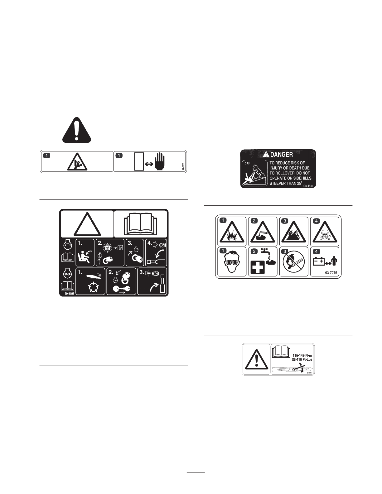
Safety and Instruction Decals
Safety decals and instructions are easily visible to the operator and are located near any area
of potential danger. Replace any decal that is damaged or lost.
94-3353
1. Crushing hazard of fingers and hands—keep hands away.
This unit does not exceed a vibration level of 2.5 m/s2 at
the hands based on measurements of identical machines per
ISO 5349 procedures.
This unit does not exceed a vibration level of 0.5 m/s2 at
the posterior based on measurements of identical machines
per ISO 2631 procedures.
100-4837
99-3558 (for CE)
1. Warning—read the operator’s manual.
2. To start the engine, sit on the seat and rotate the ignition key to
On/Preheat until the glow plug indicator light goes out. Rotate
the key to start and disengage the parking brake. Read the
operator’s manual for further instructions.
3. To stop the engine, disengage the cutting units, rotate the
ignition key to Off, and remove the key. Engage the parking
brake. Read the operator’s manual for further instructions.
93-7276
1. Explosion hazard—wear
eye protection.
2. Caustic liquid
hazard—flush with water
and get medical help fast.
3. Fire hazard—fire, open
light, and smoking
prohibited.
4. Toxic hazard—keep
children away from the
battery.
93-7818
1. Warning—read the operator’s manual for blade torque
instructions.
7

107-7801 (for CE)
1. Tipping hazard—do not drive on slopes greater than 15
degrees.
104-0484
43-8480
93-6681
1. Cutting/dismemberment hazard—stay away from moving parts.
99-3444
1. Reel speed—fast 2. Reel speed—slow
1. Height of cut
104-1086
8
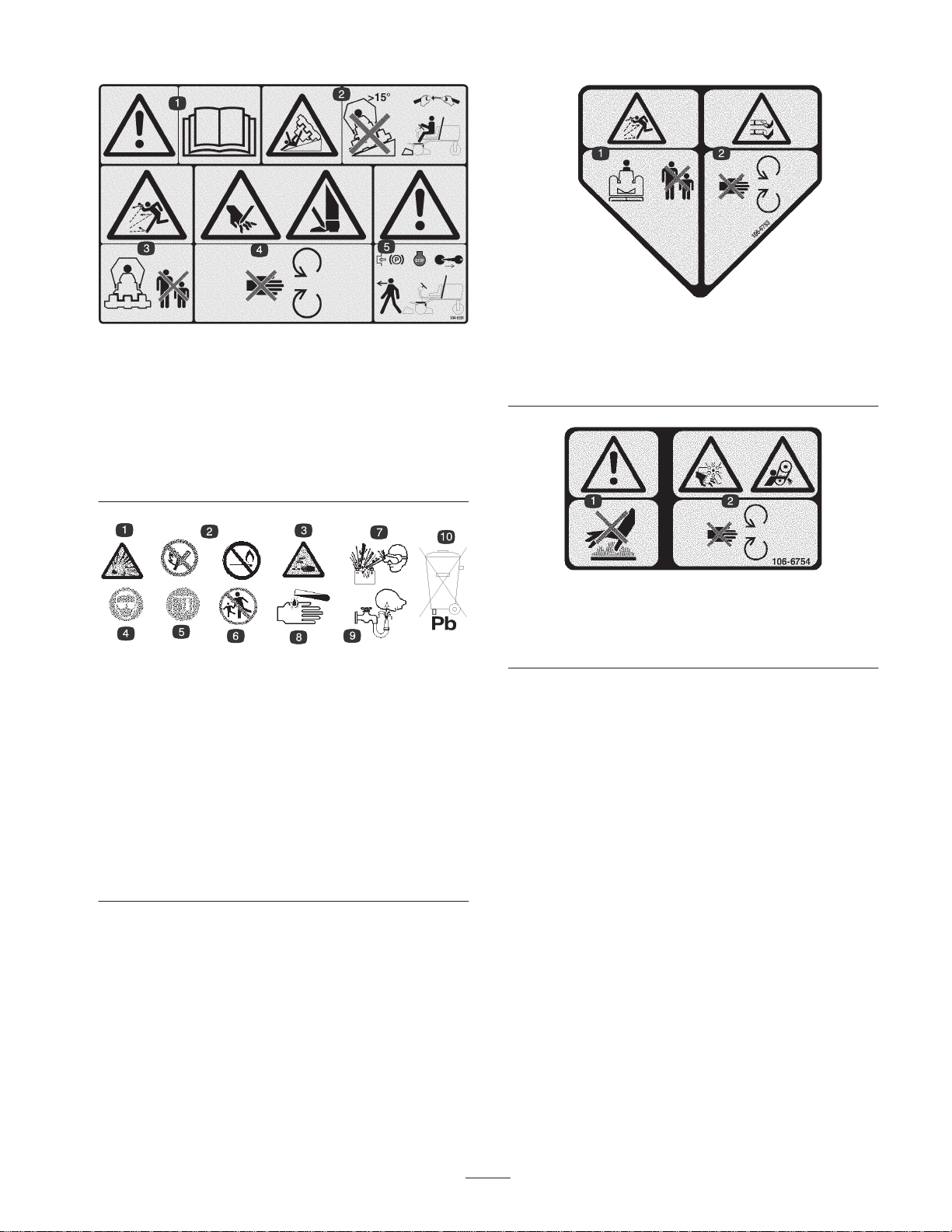
104-5181 (for CE)
1. Warning—read the
2. Tipping hazard—do not drive on slopes greater than 15
degrees and, if the roll bar is installed, wear the seat belt.
3. Thrown object hazard—keep bystanders a safe distance from
the machine.
4. Cutting hazard of hand or foot—stay away from moving parts.
5. Warning—lock the parking brake, stop the engine, and remove
the ignition key before leaving the machine.
Operator’s Manual.
Battery Symbols
Some or all of these symbols are on your battery.
1. Explosion hazard
2. No fire, open flames, or
smoking.
3. Caustic liquid/chemical
burn hazard
4. Wear eye protection
5. Read the
Manual.
6. Keep bystanders a safe
distance from the battery.
Operator’s
7. Wear eye protection;
explosive gases can
cause blindness and
other injuries
8. Battery acid can cause
blindness or severe
burns.
9. Flush eyes immediately
with water and get
medical help fast.
10. Contains lead; do not
discard.
106-6753 (for CE)
1. Thrown object
hazard—keep bystanders
a safe distance from the
machine.
2. Cutting/dismemberment
hazard of hand or foot,
mower blade—stay away
from moving parts.
106-6754
1. Warning—do not touch the hot surface.
2. Cutting/dismemberment hazard, fan and entanglement hazard,
belt—stay away from moving parts
9

1. Engage the power take off
(PTO).
2. Disengage the power take
off (PTO).
104–5191
3. Lower the cutting units.
4. Move the cutting units to the
right.
5. Raise the cutting units.
6. Move the cutting units to the
left.
7. Move rear ward to lock the
lift lever.
8. Engine—stop
9. Engine—run
10. Engine=start
11. Fast
12. Continuous variable setting
13. Slow
107-7800
10

Specifications
General Specifications
Kubota three-cylinder, 4-cycle liquid-cooled diesel engine. 32 hp @ 2800 RPM,
Engine
governed to 3050 RPM. 68.5 cu. in. (1124 cc) displacement. Heavy-duty, 2-stage,
remote mounted air cleaner. High water temperature shutdown switch.
Cooling system
Electrical
Fuel capacity 11 gallons
Traction drive
Hydraulic oil capacity/filter Remote mounted, 3.5 gallon oil reservoir. 10 micron remote mounted spin on filter.
Ground speed
Tires/wheels
Frame
Steering Power steering
Brakes
Radiator capacity is approximately 6 qt. of 50/50 mixture of ethylene glycol
anti-freeze. Remote mounted 1 qt. expansion tank.
12 volt Group 55, 585 cold cranking amps at 0°F (–18°C), 95 minute reserve
capacity at 80°F (27°C). 40 amp alternator with regulator/rectifier . Seat switch,
PTO, parking brake and traction interlock switches.
High torque hydraulic wheel motors, 3-wheel drive, oil cooler and shuttle valve
provide positive closed-loop cooling.
Infinitely variable speed selection in forward and reverse
Mowing speed: 0–6 MPH (adjustable)
Transport speed: 0–9 MPH
Reverse speed: 0–3.5 MPH
Front tires are 20 x 12-10 and rear tires are 20 x 10-10 tubeless, 4-ply rating with
demountable rims. Recommended tire pressure: 14–18 psi front and rear tires.
Tricycle vehicle with 3-wheel traction drive and rear wheel steering. Frame consists
of formed steel, welded steel, and steel tubing components.
Service braking accomplished through dynamic characteristics of Hydrostat.
Parking or emergency brake is actuated by over-center hand lever on the
operator’s right-hand side.
Foot operated forward and reverse traction pedals and mow/transport slide. Hand
Controls
Gauges and protective
systems
Seat Optional standard or deluxe seats
Cutting unit lift Hydraulic lift with automatic shut off
Note: Specifications and design subject to change without notice.
operated throttle, ignition switch, blade engagement switch, cutting unit lift, and shift
lever, parking brake, and seat adjustment.
Hour meter, 4 light warning cluster gauge: oil pressure, water temperature, amps,
glow plug, and side hill angle indicator.
Optional Equipment
Standard Seat Model No. 03224
11

Setup
Note: Determine the left and right sides of the machine from the normal operating position.
Loose Parts
Note: Use this chart as a checklist to ensure that all parts necessary for assembly have been received. Without these parts,
total setup cannot be completed. Some parts may have already been assembled at the factory.
Description Qty. Use
Hood lock bracket
Screw, 1/4 x 1-1/2 in.
Flat washer, 1/4 in.
Locknut, 1/4 in.
Exhaust guard
Self-tapping screw
Inclinometer 1 For site survey before operating the machine
EEC Decal 6 Affix to machine for European compliance.
Key
EEC certificate
Parts Catalog
Operator’s Manual
Engine manual
Operator video 1 View before operating the machine.
Pre-delivery check list 1 Fill out before delivering to the customer.
1
1
1
1
1
4
2
1
1
2
1
Mount to the hood for European compliance.
Mount to machine for European compliance.
Read before operating the machine.
12
Activating, Charging, and
Connecting the Battery
Warning
CALIFORNIA
Proposition 65 Warning
Battery posts, terminals, and related accessories
contain lead and lead compounds, chemicals
known to the State of California to cause cancer
and reproductive harm. Wash hands after
handling.
Note: If the battery is not filled with electrolyte or
activated, bulk electrolyte with 1.260 specific gravity must
be purchased from a local battery supply outlet and added
to the battery.
Danger
Battery electrolyte contains sulfuric acid which is a
deadly poison and causes severe burns.
• Do not drink electrolyte and avoid contact with
skin, eyes or clothing. Wear safety glasses to
shield your eyes and rubber gloves to protect
your hands.
• Fill the battery where clean water is always
available for flushing the skin.
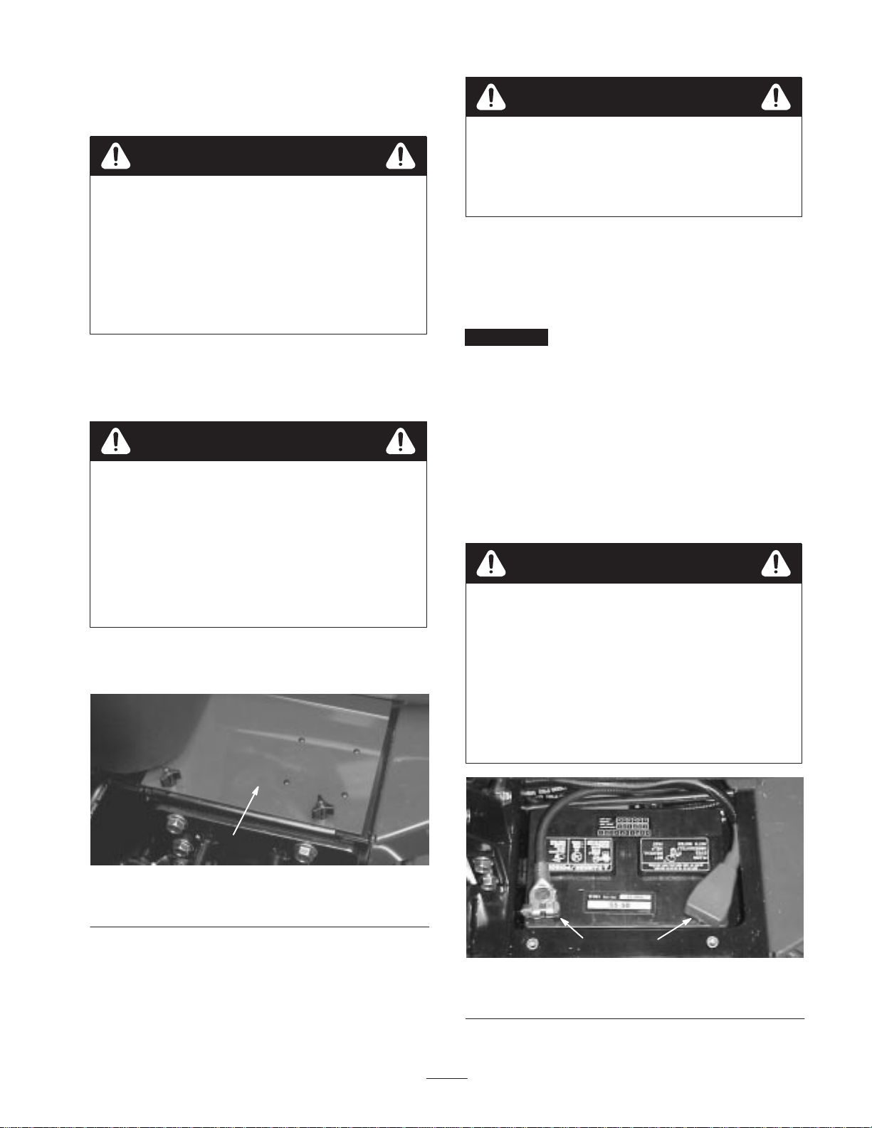
1. Open the hood.
2. Remove the battery cover (Fig. 1).
Warning
Charging the battery produces gasses that can
explode.
Never smoke near the battery and keep sparks and
flames away from battery.
5. When the battery is charged, disconnect the charger
from the electrical outlet and battery posts.
6. Remove the filler caps. Slowly add electrolyte to each
cell until the level is up to the fill ring. Install the filler
caps.
Important Do not overfill the battery. Electrolyte will
overflow onto other parts of the machine and severe
corrosion and deterioration will result.
7. Install the positive cable (red) to the positive (+)
terminal and the negative cable (black) to the negative
(–) terminal of the battery and secure them with
capscrews and nuts (Fig. 2). Make sure that the positive
(+) terminal is all of the way onto the post and the cable
is positioned snug to the battery. The cable must not
contact the battery cover. Slide the rubber boot over the
positive terminal to prevent a possible short from
occurring.
Warning
Incorrect battery cable routing could damage the
tractor and cables causing sparks. Sparks can
cause the battery gasses to explode, resulting in
personal injury.
• Always disconnect the negative (black) battery
cable before disconnecting the positive (red)
cable.
• Always connect the positive (red) battery cable
before connecting the negative (black) cable.
1
Figure 1
1. Battery cover
3. Remove the filler caps from the battery and slowly fill
each cell until electrolyte is just above the plates.
4. Install the filler caps and connect a 3 to 4 amp. battery
charger to the battery posts. Charge the battery at a rate
of 3 to 4 amperes for 4 to 8 hours.
2
1. Positive (+) battery cable 2. Negative (–) battery cable
13
1
Figure 2
Important If the battery is ever removed, make sure
that battery clamp bolts are reinstalled with the bolt heads
positioned on the bottom side and the nuts on the top side.
If the clamp bolts are reversed, they may interfere with the
hydraulic tubes when shifting the cutting units.
8. Coat both battery connections with Grafo 112X (skin
over) grease, Toro Part No. 505-47, petroleum jelly, or
light grease to prevent corrosion. Slide the rubber boot
over the positive terminal.
9. Install the battery cover.
1
2
3
Installing the Seat
The machine is shipped without the seat assembly. Deluxe
Seat Kit, Model No. 03225 or Standard Seat Kit, Model
No. 03224, must be installed as follows:
1. Remove the screws, washers, and spacers securing the
seat mounting straps to the traction unit frame (Fig. 3).
2
Figure 3
1. Seat mounting strap (2) 2. Spacer (2)
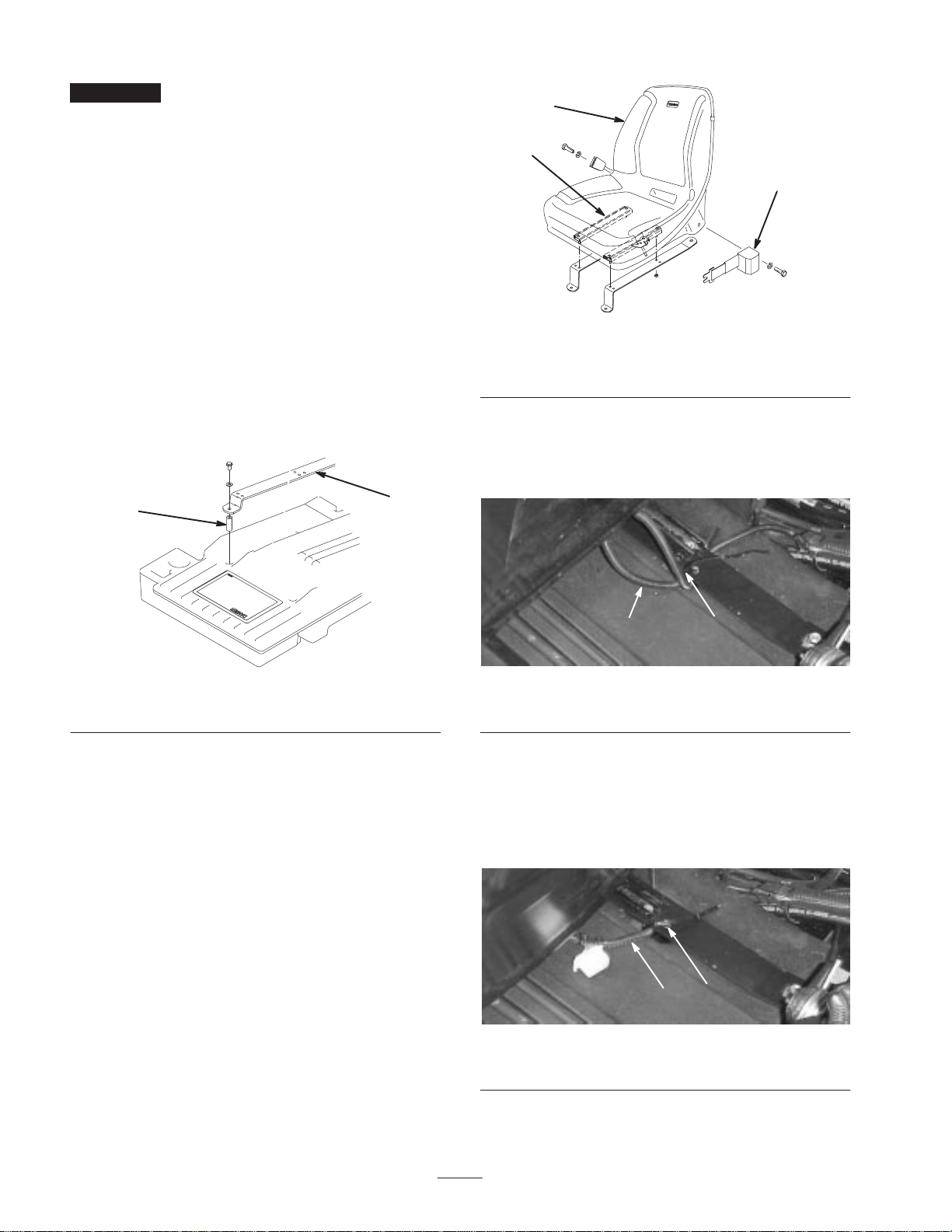
2. Secure the seat mounting straps to the seat adjusters
with 4 flange nuts (standard seat) or 4 bolts, flat
washers, and flange nuts (deluxe seat) (Fig. 4). The
mounting fasteners are supplied with the seat kits.
3. Attach the seat belt to the holes on each side of the seat
with 2 bolts and lockwashers (standard seat) or 2 bolts
and locknuts (deluxe seat) (Fig. 4). All mounting
fasteners are supplied with the seat kits.
1
Figure 4
1. Standard seat
2. Seat adjusters
3. Seat belt
6. On the deluxe seat only, route the unused seat switch
connector back under the seat strap and secure both
wires to the rear-most hole in the seat strap (Fig. 5) with
a cable tie (cable tie supplied with seat kit).
1
2
Figure 5
1. Seat switch wire 2. Cable tie
7. On the standard seat only, slide the seat all of the way
forward, pull the wire to the right so that the unused
connector is positioned as shown in Figure 6, and
secure the seat switch wire to the rear-most hole in the
seat strap with a cable tie (cable tie supplied with seat
kit).
4. Position the seat and seat straps on the frame aligning
mounting holes.
5. Route the seat switch wire under the right-hand seat
strap and connect it to the appropriate seat switch
connector on the wire harness.
1
Figure 6
1. Seat switch wire 2. Cable tie
14
2
8. Mount the seat straps to the frame with the fasteners
and spacers removed in step 1.
9. Slide the seat completely forward and backward to
ensure proper operation and that the seat switch wires
and connectors are not pinched or do no contact any
moving parts.
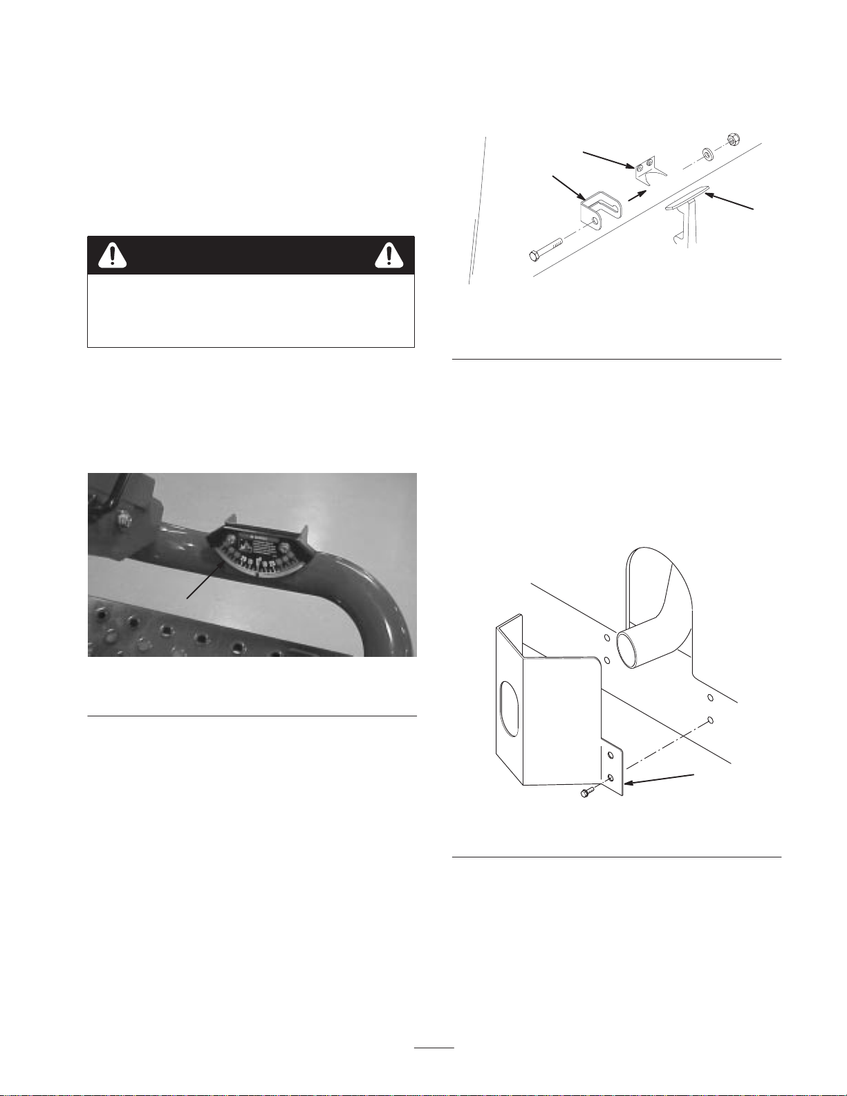
4. Insert a bolt (1/4 x 1-1/2 in.) through the hood lock
bracket and secure it with a flat washer and locknut
(Fig. 8).
2
3
Checking the Angle Indicator
Danger
To reduce risk of injury or death due to rollover,
do not operate the machine on side hills steeper
than 25.
1. Park the machine on a flat, level surface.
2. Verify that the machine is level by placing a hand held
inclinometer (supplied with the machine) on the frame
cross rail, by the fuel tank (Fig. 7). The inclinometer
should read zero degrees when viewed from the
operator’s position.
1
Figure 8
1. Hood latch
2. Hood latch bracket
3. Hood lock bracket
Installing the Exhaust Guard
(CE)
1. Position the exhaust guard around the muffler while
aligning the mounting holes with the holes in the frame
(Fig. 9).
2. Secure the exhaust guard to the frame with 4
self-tapping screws (Fig. 9).
1
Figure 7
1. Angle indicator
3. If the inclinometer does not read zero degrees, move the
machine to a location where a zero degree reading is
obtained. The angle indicator, mounted on the machine,
should now read zero degrees as well.
4. If the angle indicator does not read zero degrees, loosen
the two screws and nuts securing the angle indicator to
the mounting bracket, adjust the indicator to obtain a
zero degree reading, and tighten the capscrews.
Installing the Hood Latch (CE)
1. Unhook the hood latch from the hood latch bracket
(Fig. 8).
2. Slide the hood lock bracket onto the latch (Fig. 8).
3. Hook the latch onto the hood latch bracket (Fig. 8).
1
Figure 9
1. Exhaust guard
15
 Loading...