

Page 1

Debris Blower
200 Series Groundsmaster
Model No. 30823—Serial No. 250000001 and Up
Form No. 3350–961
Operator ’s Manual
English (EN, GB)
Page 2

Warning
Introduction
CALIFORNIA
Proposition 65 Warning
Diesel engine exhaust and some of its constituents
are known to the State of California to cause
cancer, birth defects, and other reproductive harm.
Contents
Introduction 2. . . . . . . . . . . . . . . . . . . . . . . . . . . . . . . .
Safety 3. . . . . . . . . . . . . . . . . . . . . . . . . . . . . . . . . . . . .
Safe Operating Practices 3. . . . . . . . . . . . . . . . . . . .
Sound Pressure Level 4. . . . . . . . . . . . . . . . . . . . . .
Sound Power Level 4. . . . . . . . . . . . . . . . . . . . . . .
Vibration Level 4. . . . . . . . . . . . . . . . . . . . . . . . . . .
Safety and Instruction Decals 5. . . . . . . . . . . . . . . .
Specifications 6. . . . . . . . . . . . . . . . . . . . . . . . . . . . . . .
Blower Specifications 6. . . . . . . . . . . . . . . . . . . . .
Optional Equipment 6. . . . . . . . . . . . . . . . . . . . . . .
Setup 7. . . . . . . . . . . . . . . . . . . . . . . . . . . . . . . . . . . . .
Loose Parts 7. . . . . . . . . . . . . . . . . . . . . . . . . . . . . .
Installing Frame Mount to Traction Unit 7. . . . . . .
Install Castor Wheel Assemblies 8. . . . . . . . . . . . .
Install Stand 8. . . . . . . . . . . . . . . . . . . . . . . . . . . . .
Mount Frame Mount To Blower 8. . . . . . . . . . . . . .
Install Drive Shaft 9. . . . . . . . . . . . . . . . . . . . . . . .
Rear Ballast 9. . . . . . . . . . . . . . . . . . . . . . . . . . . . .
Grease Blower 9. . . . . . . . . . . . . . . . . . . . . . . . . . .
Operation 10. . . . . . . . . . . . . . . . . . . . . . . . . . . . . . . . . .
Transporting Blower 10. . . . . . . . . . . . . . . . . . . . . . .
Adjust Discharge Opening 10. . . . . . . . . . . . . . . . . .
Maintenance 11. . . . . . . . . . . . . . . . . . . . . . . . . . . . . . . .
Lubrication 11. . . . . . . . . . . . . . . . . . . . . . . . . . . . . .
Adjusting Blower Belt 12. . . . . . . . . . . . . . . . . . . . .
Troubleshooting 13. . . . . . . . . . . . . . . . . . . . . . . . . . . . .
Storage 14. . . . . . . . . . . . . . . . . . . . . . . . . . . . . . . . . . . .
The Toro General Commercial Products Warranty 16. .
Page
Read this manual carefully to learn how to operate and
maintain your product properly. The information in this
manual can help you and others avoid injury and product
damage. Although Toro designs and produces safe
products, you are responsible for operating the product
properly and safely.
Whenever you need service, genuine Toro parts, or
additional information, contact an Authorized Service
Dealer or Toro Customer Service and have the model and
serial numbers of your product ready. The numbers can be
found on a plate that is mounted on the blower housing.
Write the product model and serial numbers in the space
below:
Model No.
Serial No.
This manual identifies potential hazards and has special
safety messages that help you and others avoid personal
injury and even death. Danger, Warning, and Caution are
signal words used to identify the level of hazard. However,
regardless of the hazard, be extremely careful.
Danger signals an extreme hazard that will cause serious
injury or death if you do not follow the recommended
precautions.
Warning signals a hazard that may cause serious injury or
death if you do not follow the recommended precautions.
Caution signals a hazard that may cause minor or moderate
injury if you do not follow the recommended precautions.
This manual uses two other words to highlight information.
Important calls attention to special mechanical
information and Note: emphasizes general information
worthy of special attention.
2004 by The Toro Company
8111 Lyndale Avenue South
Bloomington, MN 55420-1196
All Rights Reserved
Printed in the USA
2
Page 3

Safety
– Do not fill tank while engine is hot or running.
– Do not smoke while handling gasoline.
Safe Operating Practices
Hazard control and accident prevention are dependent
upon the awareness, concern, and proper training of the
personnel involved in the operation, transport,
maintenance, and storage of the machine. Improper use
or maintenance of the machine can result in injury or
death. To reduce the potential for injury or death,
comply with the following safety instructions.
Before Operating
• Never allow children to operate the machine. Do not
allow adults to operate machine without proper
instruction. Only trained operators who have read this
manual should operate this machine.
• Never operate the machine when under the influence of
drugs or alcohol.
• Keep all bystanders away from the operating area.
• Keep all shields and safety devices in place. If a shield,
safety device or decal is illegible or damaged, repair or
replace it before operation is commenced. Also tighten
any loose nuts, bolts and screws to assure machine is in
safe operating condition.
• Do not operate machine while wearing sandals, tennis
shoes, sneakers or shorts. Also, do not wear loose fitting
clothing which could get caught in moving parts.
Always wear long pants and substantial shoes. Wearing
safety glasses, safety shoes and a helmet is advisable
and required by some local ordinances and insurance
regulations.
• Check interlock switches daily for proper operation
(Refer To Section in Traction Unit Operator’s Manual
on Checking Interlock Switches). Do not rely entirely
on safety switches - shut off engine before getting off
seat. If a switch fails, replace it before operating the
machine. The interlock system is for your protection, so
do not bypass it. Replace all interlock switches every
two years. Interlock switches should be adjusted so:
– Engine cannot be started unless traction pedal is
released (neutral position) and PTO switch is
DISENGAGED (off position).
– Engine stops if operator gets off seat when traction
pedal is depressed.
– Engine stops if operator gets off seat when PTO
lever is ENGAGED (on position).
• Fill fuel tank before starting the engine. Avoid spilling
any fuel. Since fuel is flammable, handle it carefully.
– Use an approved fuel container.
– Fill fuel tank outdoors and up to about one inch
from top of the tank, not the filler neck.
– Wipe up any spilled gasoline.
While Operating
• Do not run the engine in a confined area without
adequate ventilation. Exhaust fumes are hazardous and
could possibly be deadly.
• Maximum seating capacity is one person. Never carry
passengers.
• Sit on the seat when starting the engine and operating
the machine.
• This product may exceed noise levels of 85 dB(A) at
the operator position. Ear protectors are recommended
for prolonged exposure to reduce the potential of
permanent hearing damage.
• Before starting the engine:
A. Engage the parking brake.
B. Ensure traction pedal is in neutral and PTO is in the
OFF, disengaged position.
C. After engine is started, release parking brake and
keep foot off traction pedal. Machine must not
move. If movement is evident, the neutral return
mechanism is adjusted incorrectly; therefore, shut
engine off and adjust until machine does not move
when traction pedal is released.
• Using the machine demands attention, and to prevent
loss of control:
– Operate only in daylight or when there is good
artificial light.
– Drive slowly and watch for holes or other hidden
hazards.
– Do not drive close to a sand trap, ditch, creek or
other hazard.
– Reduce speed when making sharp turns and when
turning on hillsides.
– Avoid sudden starts and stops.
– Before backing up, look to the rear and assure no
one is behind the machine.
– Watch out for traffic when near or crossing roads.
Always yield the right–of –way.
• Stay away from discharge opening when machine is
operating. Keep all bystanders away from the discharge
opening and don’t direct discharge toward bystanders.
3
Page 4

• If engine stalls or machine loses headway and cannot
make it to the top of a slope, do not turn machine
around. Always back slowly straight down the slope.
• DON’T TAKE AN INJURY RISK! When a person or
pet appears unexpectedly in or near the operating area,
STOP OPERATION. Careless operation, combined
with terrain angles, ricochets, or improperly positioned
guards can lead to thrown object injuries. Do not
resume operation until area is cleared.
• Do not touch engine or muffler while engine is running
or soon after it is stopped. These areas could be hot
enough to cause a burn.
• Before getting off the seat:
• Before disconnecting or performing any work on the
hydraulic system, all pressure in system must be
relieved by stopping engine and lowering blower to the
ground.
• If the engine must be running to perform a maintenance
adjustment, keep hands, feet, clothing and other parts of
the body away from the fan and other moving parts.
• Do not overspeed the engine by changing governor
settings. To be sure of safety and accuracy, have an
Authorized TORO Distributor check maximum engine
speed with a tachometer.
• Engine must be shut off before checking oil or adding
oil to the crankcase.
– Move traction pedal to neutral position and remove
foot from pedal.
– Set the parking brake and disengage the PTO.
– Shut the engine off and remove the key from the
ignition switch. Wait for all movement to stop
before getting off the seat.
• Lower the blower to the ground and remove key from
ignition switch whenever machine is left unattended.
Maintenance
• Remove key from ignition switch to prevent accidental
starting of the engine when servicing, adjusting or
storing the machine.
• Perform only those maintenance instructions described
in this manual. If major repairs are ever needed or
assistance is desired, contact an Authorized Toro
Distributor.
• To reduce potential fire hazard, keep the engine free of
excessive grease, grass, leaves and accumulations of
dirt. Never wash a warm engine or any electrical parts
with water.
• Be sure machine is in safe operating condition by
keeping nuts, bolts and screws tight. Check the rotor
bearing mounting bolts and nuts frequently to be sure
they are tightened to specification.
• Make sure all hydraulic line connectors are tight, and all
hydraulic hoses and lines are in good condition before
applying pressure to the system.
• Keep body and hands away from pin hole leaks in
hydraulic lines that eject high pressure hydraulic fluid.
Use cardboard or paper to find hydraulic leaks.
Hydraulic fluid escaping under pressure can penetrate
skin and cause injury. Fluid accidentally injected into
the skin must be surgically removed within a few hours
by a doctor familiar with this form of injury or gangrene
may result.
• At the time of manufacture the blower conformed to
safety standards in effect for riding mowers. Therefore,
to ensure optimum performance and safety, always
purchase genuine TORO replacement parts and
accessories to keep the Toro all TORO. NEVER USE
“WILL–FIT” REPLACEMENT PARTS AND
ACCESSORIES MADE BY OTHER
MANUFACTURERS. Look for the TORO logo to
assure genuineness. Using unapproved replacement
parts and accessories could void the warranty of The
Toro Company.
Sound Pressure Level
A GM 2XX series traction unit with the debris blower
attachment has an equivalent continuous A–weighted sound
pressure at the operator ear of: 98 dB(A), based on
measurements of identical machines per SAE Jl174– Mar
85 procedures.
Sound Power Level
A GM 2XX series traction unit with the debris blower
attachment has a sound power level of: 110 dB(A) / I pW,
based on measurements of identical machines per
prbcedures outlined in Directive 79/113/EEC and
amendments.
Vibration Level
Hand–Arm
A GM 2XX series traction unit with the debris blower
attachment does not exceed a vibration level of 4.0 m/s2 at
the hands based on measurements of identical machines per
ISO 5349 procedures.
Whole Body
A GM 2XX series traction unit with the debris blower
attachment does not exceed a vibration level of 0.5 m/s
the posterior, based on measurements of identical machines
per ISO 2631 procedures.
2
at
4
Page 5
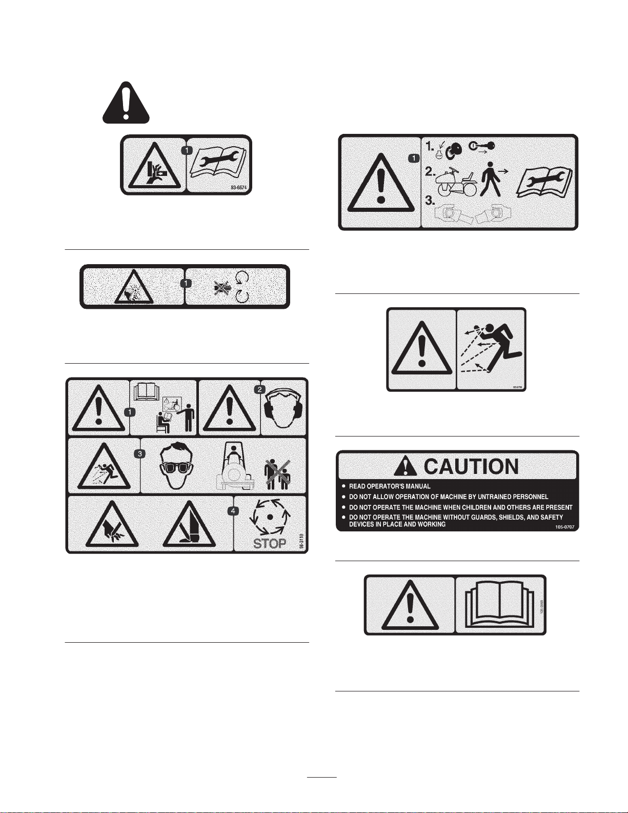
Safety and Instruction Decals
Safety decals and instructions are easily visible to the operator and are located near any area
of potential danger. Replace any decal that is damaged or lost.
93-6674
1. Crushing hazard, hand—read the instructions before servicing
or performing maintenance.
93-9083
1. Cutting/dismemberment hazard, fan—stay away from moving
parts.
98-3113
1. Warning—stop the engine and remove the key before leaving
the machine or disconnecting the PTO shaft; read the
instructions before servicing or performing maintenance.
98-3110
1. Warning—read the
2. Warning—wear hearing protection.
3. Thrown object hazard—wear eye protection and keep
bystanders a safe distance from the machine.
4. Cutting hazard of hand or foot—wait for moving parts to stop.
Operator’s Manual
and receive training.
1. Warning—thrown objects
Place over decal 105–0707 for CE
1. Warning—read the
Operator’s Manual.
105-0708
105-0707
105-0698
5
Page 6

98-3114
1. Entanglement hazard—stay away from moving parts.
98-3115
1. Rotating shaft
Specifications
Blower Specifications
98-3137
1. Read the
Manual.
1. Warning—read the instructions before servicing or performing
maintenance on the electrical wiring.
Operator’s
2. Grease
3. Grease every 8 hours.
98-3112
Fan
Fan Housing
Fan Drive
Fan Speed 2700 rpm.
Fan Output 3650 +/– 200 CFM, 130 +/– 20 mph.
Outlet Outlet opening is 47 square inches.
Weight 300 lbs.
Note: Specifications subject to change without notice.
Backward curved, cast aluminum fan. 12 blades per side, 21” outside diameter ,
6.375” width, 34 lbs.
10 gauge steel face plates welded to 10 gauge wrapper. Increasing scroll from
cutoff.
PTO driven A 3VX banded belt drive to fan. Final drive ratio of 1.2:1 with a over
running clutch on fan shaft. Fan shaft rotates on greaseable ball bearing.
Optional Equipment
Discharge Chute Kit Model No. 08860
Counterbalance Kit Model No. 30712
6
Page 7

Setup
Note: Determine the left and right sides of the machine from the normal operating position.
Loose Parts
Note: Use this chart as a checklist to ensure that all parts necessary for assembly have been received. Without these parts,
total setup cannot be completed. Some parts may have already been assembled at the factory.
Description Qty. Use
Frame Mount
Pivot Pin
Cotter Pin–5/32 x 1–3/4
Capscrew
Flatwasher
Nut
Drive Shaft
Capscrew
Nut
Roll Pin
Decal 1 Apply over decal part number 105–0707 for CE
Operator’s Manual 1 Read Before Operating Machine
Part Catalog 1
Danger
Do not start the engine and engage the PTO lever
when PTO shaft is not connected to blower gear
box because the PTO shaft will rotate with enough
force to cause serious injury.
Installing Frame Mount to
1
2
2
6
12
6
1
4
4
2
Install frame mount to blower & traction unit
Mount drive shaft to blower & traction unit
4. Jack up machine until the front wheel is off the floor.
Use jack stands or block the machine to prevent it from
falling accidentally.
5. Remove wheel nuts and slide wheel and tire assembly
off studs.
6. Mount frame mount to pivot bracket with a large pivot
pin and cotter pin (Fig. 1). Grease fitting to be
positioned downward.
Traction Unit
Note: Traction unit must be equipped with larger carrier
bracket pin, part no. 98–2328. If the traction unit serial
number is 70001 or prior and is equipped with old style
bracket, part no. 92–9786, a new bracket must be obtained
from your Toro Distributor.
1. Park the machine on a level surface, lower the cutting
unit to the floor, engage the parking brake, be sure the
traction pedal is in the neutral position, the PTO lever is
in the OFF position, shut the engine OFF and remove
the key from the switch. Move lift lever to FLOAT
position.
2. Remove the cutting unit or other attachment from the
traction unit. Refer to cutting unit or attachment
operator’s manual.
3. On right side of the traction unit, loosen (do not
remove) the wheel nuts securing wheel and tire
assembly to front wheel studs.
1
Right Side Shown
Figure 1
1. Pivot pin
2. Frame mount
7. Mount rear of frame mount to lift cylinder with pivot
pin and (2) cotter pins (supplied with traction unit).
8. Hook brake return spring to hole in frame mount.
7
3
3. Lift arm pivot bracket
4. Brake return spring
2
4
Page 8

9. Install wheel and tire assembly. Torque wheel nuts to
45–55 ft–lbs.
3. Assure both castor wheels are set at same height.
10.Repeat procedure on left side of machine.
Note: Install drive shaft to traction unit before installing
left wheel and tire assembly.
11. Slide drive shaft onto traction unit PTO shaft. Align
mounting holes in each shaft and slide together.
12.Secure with roll pin and (2) capscrews and nuts.
Install Castor Wheel
Assemblies
The castor wheel assemblies are installed upside down on
the debris blower for shipping.
1. Remove tensioning caps from spindle shafts and slide
off castor wheel, spacers and thrust washers (Fig. 2).
2. Slide spacers onto castor spindle to get desired height.
Slide a thrust washer onto spindle, push castor spindle
through frame. Install another thrust washer and
remaining spacers onto spindle and install tensioning
cap to secure assembly.
1
3
Install Stand
1. Remove snapper pin securing stand to tube on blower
frame (Fig. 3).
1
2
Figure 3
1. Snapper pin 2. Stand tube
2. Lower stand. Re–install pin through upper set of holes
in stand and tube. Secure pin.
3. Remove snapper pin securing stand to tube on blower
frame.
4. Raise stand. Re–install pin through lower set of holes in
stand and tube. Secure pin.
2
2
Figure 2
1. Tensioning cap
2. Thrust washers
Important Thrust washers – not the spacers – must
contact the top and bottom of the blower frame.
3. Spacers
4. Front castor spindle
5. Stand blower up on castor wheels and stand (Storage
position).
Mount Frame Mount To Blower
1. Position traction unit/frame mount in line with rear of
Debris Blower.
2. Align frame mount tubes with mounting holes in blower
frame (Fig. 4).
2
1
Figure 4
1. Frame mounting tube 2. Blower
8
Page 9

3. Mount each frame mount tube to blower frame with (3)
capscrews, (6) washers and (3) nuts.
Install Drive Shaft
1. Remove (3) capscrews, (6) washers and (3) nuts
securing belt guard to blower frame (Fig. 5).
1
2
Figure 5
1. Belt guard 2. PTO shaft
Rear Ballast
A GM 2XX series 2WD traction unit complies with the
ANSI B71.4–1990 Standard when (4) 35 lb. weights are
installed. Order two Weight Kits, Part No. 24–5780 from
your Toro Distributor.
Grease Blower
Before the Debris Blower is operated, the PTO shaft must
be greased to assure proper lubricating characteristics: refer
to Lubrication section of manual. Failure to properly grease
the unit will result in premature failure of critical parts.
2. Slide shafts together.
3. Slide drive shaft onto blower shaft. Align mounting
holes in each shaft and slide together.
4. Secure with roll pin and (2) capscrews and nuts.
5. Re–install belt shaft guard with fasteners previously
removed.
Note: To assure proper blower operation, check/adjust
blower belt tension after first 20 hours of operation. Refer
to Adjusting Blower Belt.
9
Page 10

Operation
Operating Tips
Warning
Adjust Discharge Opening
The discharge opening is adjustable to increase or decrease
air output velocity and volume. Decreasing discharge
opening size will increase velocity.
1. Loosen discharge opening deflector mounting screws
(Fig. 6).
Discharged air has considerable force and could
cause injury or loss of footing.
• Stay away from discharge opening when
machine is operating.
• Keep bystanders away from discharge opening
when machine is running.
• Start the traction unit and run at a low RPM.
• Lower the blower using the traction unit lift
mechanism.
• Engage the PTO while the engine is at idle speed.
• Increase the PTO speed to 1800 RPM.
• Practice blowing material. It is advisable to blow the
same direction the wind is blowing to prevent material
from blowing back into the cleared area.
Transporting Blower
• Reduce the engine speed to idle position.
• Disengage the PTO and wait for the PTO to stop.
• Raise the blower to transport position.
1
2
Figure 6
1. Deflector 2. Mounting screw
2. Pivot deflector to desired opening.
3. Tighten mounting screws.
10
Page 11

Maintenance
Lubrication
The Idler arm bearing (Fig. 7) must be lubricated after
every 8 hours of operation with a No. 2 Lithium based
grease.
Figure 7
The (2) mount frame pivots (Fig. 9) must be lubricated
after every 8 hours of operation with a No. 2 Lithium based
grease.
Figure 9
Under normal conditions, grease the (2) drive shaft fittings
(Fig. 10) after every 100 hours of use and guards after
every 8 hours of operation. Use a No. 2 Lithium based
grease.
The overrunning clutch pulley (Fig. 7) must be lubricated
after every 8 hours of operation with a No. 2 Lithium based
grease.
The (2) fan shaft bearings (Fig. 7 & 8) must be lubricated
after every 8 hours of operation with a No. 2 Lithium based
grease.
Figure 8
Figure 10
Under normal conditions, grease the (2) castor wheels and
(2) wheel pivot tubes (Fig. 8) after every 50 hours of use.
Use a No. 2 Lithium based grease.
11
Page 12

Adjusting Blower Belt
Make sure belt is properly tensioned to assure proper
operation of the machine and unnecessary wear. Check belt
frequently.
Note: Check/adjust blower belt tension after first 20 hours
of operation.
1. Remove (3) capscrews. (6) washers and (3) nuts
securing belt guard to blower housing (Fig. 11).
Remove guard.
Note: Drive shaft does not have to be disconnected to
adjust belt.
1
3. When belt stretches it can be adjusted as follows:
A. Loosen nut securing belt tensioner to blower
housing (Fig. 13).
B. Rotate belt tensioner until idler spring body is
extended to a length of 3.25 – 3.50” (Fig. 13), then
tighten nut.
2
1
Figure 13
1. Belt tensioner 2. Belt tensioner nut
Figure 11
1. Belt guard
2. A new belt will be properly tensioned, when idler
spring body is extended to a length of 3.25 – 3.50”
(Fig. 12).
1
3.25–3.50”
Figure 12
1. Idler spring
4. Install belt guard to blower housing with capscrews,
washers and nuts.
12
Page 13

Troubleshooting
Problem Possible Causes Corrective Action
Fan quit turning
Excessive vibration
Lack of adequate air flow
1. Belt may be loose or broken. 1. Replace belt or adjust the
tension of the belt.
2. Bearing pressed in the bearing
mount may be damaged.
1. Bearing on fan shaft may be
damaged.
2. Material may be built up on fan
blades.
3. RPM of the PTO shaft too fast. 3. Reduce PTO speed to 540
1. Air slots may be clogged with
debris.
2. RPM on tractor too slow. 2. Increase PTO speed to 540
3. Throttle on tractor engine may
be too slow.
2. Replace the bearing, use #609
Loctite when replacing.
1. Replace bearings.
2. Clean out any build up inside
the housing.
RPM.
1. Clean out any debris from slots.
RPM.
3. Make any necessary repairs to
bring tractor speed up to
normal.
13
Page 14

Storage
• Thoroughly clean the blower. The fan housing should
be free of dirt, leaves and debris.
• Lubricate all grease fittings. Wipe off any excess
lubricant.
• Place a light coat of grease on the splines of the PTO
adapter.
• Tighten all fasteners.
14
Page 15

15
Page 16

The Toro General Commercial Products Warranty
A Two-Year Limited Warranty
Conditions and Products Covered
The Toro Company and its affiliate, Toro Warranty Company,
pursuant to an a g r eement between them, jointly warrant your Toro
Commercial Product (“Product”) to be free from defects in
materials or workmanship for two years or 1500 operational
hours*, whichever occurs first. Where a warrantable condition
exists, we will repair the Product at no cost to you including
diagnosis, labor, parts, and transportation. This warranty begins
on the date the Product is delivered to the original retail purchaser.
* Product equipped with hour meter
Instructions for Obtaining Warranty Service
You are responsible for notifying the Commercial Products
Distributor or Authorized Commercial Products Dealer from whom
you purchased the Product as soon as you believe a warrantable
condition exists.
If you need help locating a Commercial Products Distributor or
Authorized Dealer, or if you have questions regarding your
warranty rights or responsibilities, you may contact us at:
Toro Commercial Products Service Department
Toro Warranty Company
8111 Lyndale Avenue South
Bloomington, MN 55420-1196
952-888-8801 or 800-982-2740
E-mail: commercial.service@toro.com
Owner Responsibilities
As the Product owner, you are responsible for required maintenance and adjustments stated in your operator’s manual. Failure
to perform required maintenance and adjustments can be grounds
for disallowing a warranty claim.
Items and Conditions Not Covered
Not all product failures or malfunctions that occur during the
warranty period are defects in materials or workmanship. This
express warranty does not cover the following:
• Product failures which result from the use of non-Toro
replacement parts, or from installation and use of add-on,
modified, or unapproved accessories
• Product failures which result from failure to perform required
maintenance and/or adjustments
• Product failures which result from operating the Product in an
abusive, negligent or reckless manner
• Parts subject to consumption through use unless found to be
defective. Examples of parts which are consumed, or used up,
during normal Product operation include, but are not limited to,
blades, reels, bedknives, tines, spark plugs, castor wheels,
tires, filters, belts, and certain sprayer components such as
diaphragms, nozzles, and check valves, etc.
• Failures caused by outside influence. Items considered to be
outside influence include, but are not limited to, weather,
storage practices, contamination, use of unapproved coolants,
lubricants, additives, or chemicals, etc.
• Normal “wear and tear” items. Normal “wear and tear” includes,
but is not limited to, damage to seats due to wear or abrasion,
worn painted surfaces, scratched decals or windows, etc.
Parts
Parts scheduled for replacement as required maintenance are
warranted for the period of time up to the scheduled replacement
time for that part.
Parts replaced under this warranty become the property of Toro.
T oro will make the final decision whether to repair any existing part
or assembly or replace it. Toro may use factory remanufactured
parts rather than new parts for some warranty repairs.
General Conditions
Repair by an Authorized Toro Distributor or Dealer is your sole
remedy under this warranty.
Neither The Toro Company nor Toro Warranty Company is
liable for indirect, incidental or consequential damages in
connection with t h e use of the Toro Products covered by this
warranty, including any cost or expense of providing substitute equipment or service during reasonable periods of
malfunction or non-use pending completion of repairs under
this warranty. Except for the Emissions warranty referenced
below, if applicable, there is no other express warranty. All
implied warranties of merchantability and fitness for use are
limited to the duration of this express warranty.
Some states do not allow exclusions of incidental or consequential
damages, or limitations on how long an implied warranty lasts, so
the above exclusions and limitations may not apply to you.
This warranty gives you specific legal rights, and you may also
have other rights which vary from state to state.
Note regarding engine warranty: The Emissions Control System
on your Product may be covered by a separate warranty meeting
requirements established by the U.S. Environmental Protection
Agency (EPA) and/or the California Air Resources Board (CARB).
The hour limitations set forth above do not apply to the Emissions
Control System Warranty. Refer to the Engine Emission Control
Warranty Statement printed in your operator’s manual or contained in the engine manufacturer’s documentation for details.
Countries Other than the United States or Canada
Customers who have purchased Toro products exported from the United States or Canada should contact their Toro Distributor (Dealer)
to obtain guarantee policies for your country, province, or state. If for any reason you are dissatisfied with your Distributor’s service or
have difficulty obtaining guarantee information, contact the Toro importer. If all other remedies fail, you may contact us at Toro Warranty
Company.
Part No. 374-0031 Rev. C
 Loading...