

Page 1
FormNo.3396-206RevA
Groundsmaster
®
3500-GRotary
Mower
ModelNo.30809—SerialNo.315000001andUp
Registeratwww.T oro.com.
OriginalInstructions(EN)
*3396-206*A
Page 2
WARNING
CALIFORNIA
Proposition65Warning
Thisproductcontainsachemicalorchemicals
knowntotheStateofCaliforniatocausecancer,
birthdefects,orreproductiveharm.
Theengineexhaustfromthisproduct
containschemicalsknowntotheStateof
Californiatocausecancer,birthdefects,
orotherreproductiveharm.
Figure1
Important:Thisengineisnotequippedwithaspark
arrestermufer.ItisaviolationofCaliforniaPublic
ResourceCodeSection4442touseoroperatetheengine
onanyforest-covered,brush-covered,orgrass-covered
land.Otherstatesorfederalareasmayhavesimilarlaws.
Introduction
Thismachineisaride-on,rotary-bladelawnmowerintended
tobeusedbyprofessional,hiredoperatorsincommercial
applications.Itisprimarilydesignedforcuttinggrasson
well-maintainedlawnsinparks,golfcourses,sportselds,
andoncommercialgrounds.Itisnotdesignedforcutting
brush,mowinggrassandothergrowthalongsidehighways,
orforagriculturaluses.
Readthisinformationcarefullytolearnhowtooperateand
maintainyourproductproperlyandtoavoidinjuryand
productdamage.Youareresponsibleforoperatingthe
productproperlyandsafely.
YoumaycontactTorodirectlyatwww .Toro.comforproduct
andaccessoryinformation,helpndingadealer,ortoregister
yourproduct.
1.Modelandserialnumberlocation
ModelNo.
SerialNo.
Thismanualidentiespotentialhazardsandhassafety
messagesidentiedbythesafetyalertsymbol(Figure2),
whichsignalsahazardthatmaycauseseriousinjuryordeath
ifyoudonotfollowtherecommendedprecautions.
Figure2
1.Safetyalertsymbol
Thismanualuses2wordstohighlightinformation.
Importantcallsattentiontospecialmechanicalinformation
andNoteemphasizesgeneralinformationworthyofspecial
attention.
Wheneveryouneedservice,genuineT oroparts,oradditional
information,contactanAuthorizedServiceDealerorToro
CustomerServiceandhavethemodelandserialnumbersof
yourproductready.Figure1identiesthelocationofthe
modelandserialnumbersontheproduct.Writethenumbers
inthespaceprovided.
©2015—TheToro®Company
8111LyndaleAvenueSouth
Bloomington,MN55420
Contactusatwww.Toro.com.
2
PrintedintheUSA
AllRightsReserved
Page 3

Contents
Safety...........................................................................4
SafeOperatingPractices...........................................4
SoundPowerLevel..................................................6
SoundPressureLevel...............................................6
VibrationLevel......................................................6
SafetyandInstructionalDecals.................................7
Setup...........................................................................11
1Activating,Charging,andConnectingthe
Battery..............................................................12
2CheckingtheAngleIndicator.................................13
3AdjustingtheLiftArms........................................13
4AdjustingtheCarrierFrame..................................14
5AdjustingtheHeightofCut...................................15
6CheckingtheMachinebeforeOperation..................16
7AdjustingtheOptionalRollerScraper
........................................................................16
8InstallingtheOptionalMulchingBafe
........................................................................16
ProductOverview.........................................................17
Controls...............................................................17
Specications........................................................19
Attachments/Accessories........................................19
Operation....................................................................19
ThinkSafetyFirst...................................................19
CheckingtheEngine-OilLevel.................................19
FillingtheFuelTank...............................................20
CheckingtheCoolingSystem...................................22
CheckingtheHydraulicSystem................................22
CheckingtheTirePressure......................................23
RearWheelBallast..................................................23
StartingandStoppingtheEngine..............................24
CheckingtheInterlockSystem.................................24
TowingtheTractionUnit.........................................24
StandardControlModule(SCM)..............................25
ChoosingAccessories.............................................27
SelectingaBlade.....................................................27
OperatingTips......................................................28
Maintenance.................................................................30
RecommendedMaintenanceSchedule(s)......................30
DailyMaintenanceChecklist....................................31
ServiceIntervalChart.............................................32
PremaintenanceProcedures........................................32
RemovingtheHood...............................................32
UsingtheCutting-UnitServiceLatch........................33
Lubrication...............................................................33
GreasingtheBearingsAndBushings.........................33
EngineMaintenance..................................................36
ServicingtheAirCleaner.........................................36
ChangingtheEngineOilandFilter...........................37
ReplacingtheSparkPlugs........................................37
FuelSystemMaintenance...........................................38
ReplacingtheFuel-PumpFilter................................38
ServicingtheFuelTank...........................................39
InspectingtheFuelLinesandConnections.................39
ElectricalSystemMaintenance....................................39
CaringfortheBattery..............................................39
Fuses....................................................................40
DriveSystemMaintenance.........................................40
TorquingtheWheelNuts........................................40
AdjustingtheTractionDriveforNeutral....................40
CoolingSystemMaintenance......................................41
CleaningtheEngineCoolingSystem.........................41
BrakeMaintenance....................................................42
AdjustingtheParkingBrake.....................................42
BeltMaintenance......................................................42
ServicingtheEngineBelts.......................................42
HydraulicSystemMaintenance....................................43
ChangingtheHydraulicFilter...................................43
ChangingtheHydraulicFluid...................................44
CheckingtheHydraulicLinesandHoses....................44
MaintainingtheCuttingUnit.......................................45
SeparatingtheCuttingUnitfromtheTraction
Unit..................................................................45
MountingtheCuttingUnitstotheTraction
Unit..................................................................45
ServicingtheBladePlane.........................................45
ServicingtheCutterBlade.......................................46
ServicingtheFrontRoller........................................47
Storage........................................................................49
StoringtheBattery..................................................49
PreparationforSeasonalStorage..............................49
3
Page 4

Safety
ThismachinemeetsorexceedsANSIB71.4-2012
specicationswhenequippedwithrequiredweightas
listedinRearBallastsection.
Improperuseormaintenancebytheoperatoror
ownercanresultininjury.Toreducethepotential
forinjury,complywiththesesafetyinstructionsand
alwayspayattentiontothesafetyalertsymbol,which
meansCaution,Warning,orDanger—personalsafety
instruction.Failuretocomplywiththeinstructionmay
resultinpersonalinjuryordeath.
SafeOperatingPractices
ThefollowinginstructionsareadaptedfromANSIstandard
B71.4-2012.
Training
•ReadtheOperator'sManualandothertrainingmaterial.
Iftheoperator(s)ormechanic(s)cannotreadEnglishitis
theowner'sresponsibilitytoexplainthismaterialtothem.
•Becomefamiliarwiththesafeoperationoftheequipment,
operatorcontrols,andsafetysigns.
•Alloperatorsandmechanicsshouldbetrained.The
ownerisresponsiblefortrainingtheusers.
•Neverletchildrenoruntrainedpeopleoperateorservice
theequipment.Localregulationsmayrestricttheageof
theoperator.
•Theowner/usercanpreventandisresponsiblefor
accidentsorinjuriesoccurringtopeopleordamageto
property.
Preparation
•Evaluatetheterraintodeterminewhataccessoriesand
attachmentsareneededtoproperlyandsafelyperform
thejob.Onlyuseaccessoriesandattachmentsapproved
bythemanufacturer.
•Inspecttheareawheretheequipmentistobeusedand
removeallobjectssuchasrocks,toysandwirewhichcan
bethrownbythemachine.
•Checkthatoperator'spresencecontrols,safetyswitches
andshieldsareattachedandfunctioningproperly.Donot
operateunlesstheyarefunctioningproperly.
Operation
•Thisproductiscapableofamputatinghandsandfeet,and
throwingobjects.Alwaysfollowallsafetyinstructionsto
avoidseriousinjuryordeath.
•Useofthisproductforpurposesotherthanitsintended
usecouldprovedangeroustotheuserandbystanders.
•Donotoperatetheengineinaconnedspacewhere
dangerouscarbonmonoxideandotherexhaustgasses
cancollect.
•Onlyoperateingoodlight,keepingawayfromholesand
hiddenhazards.
•Besurealldrivesareinneutralandparkingbrakeis
engagedbeforestartingengine.Onlystartenginefrom
theoperator'sposition.
•Alwayswearsubstantial,slip-resistantfootwear,long
trousers,hardhat,safetyglasses,andhearingprotection
whilemowing.Longhair,looseclothing,orjewelrymay
gettangledinmovingparts.Donotoperatethemachine
whenbarefootorwearingopensandals.
•Slowdownanduseextracareonhillsides.Besureto
travelsidetosideonhillsides.Turfconditionscanaffect
themachine'sstability.Usecautionwhileoperatingnear
drop-offs.
•Slowdownandusecautionwhenmakingturnsandwhen
changingdirectionsonslopes.
•Neverraisedeckwiththebladesrunning.
•NeveroperatewiththePTOshield,orotherguardsnot
securelyinplace.Besureallinterlocksareattached,
adjustedproperly ,andfunctioningproperly.
•Neveroperatewiththedischargedeectorraised,
removedoraltered,unlessusingagrasscatcher.
•Donotchangetheenginegovernorsettingoroverspeed
theengine.
•Beforeleavingtheoperator'spositionforanyreason
includingemptyingthecatchersoruncloggingthechute,
stoponlevelground,disengagedrives,engageparking
brake(ifprovided),shutoffengineandremovethekey
fromtheignition.
•Stopequipmentandinspectbladesafterstrikingobjects
orifanabnormalvibrationoccurs.Makenecessary
repairsbeforeresumingoperations.
•Lookbehindanddownbeforebackinguptobesureof
aclearpath.
•Keeppetsandbystandersaway .
•Slowdownandusecautionwhenmakingturnsand
crossingroadsandsidewalks.Stopbladesifnotmowing.
•Beawareofthemowerdischargedirectionanddonot
pointitatanyone.
•Donotoperatethemowerundertheinuenceofalcohol
ordrugs.
•Usecarewhenloadingorunloadingthemachineinto
orfromatrailerortruck.
•Usecarewhenapproachingblindcorners,shrubs,trees,
orotherobjectsthatmayobscurevision.
•Lightningcancausesevereinjuryordeath.Iflightning
isseenorthunderisheardinthearea,donotoperate
themachine;seekshelter.
•Knowhowtostopthemachineandenginequickly.
•Keephands,feet,andclothingawayfrommovingparts
andthecuttingunit.
4
Page 5

•Checkthesafetyinterlockswitchesdailyforproper
operation.Ifaswitchshouldfail,replacetheswitch
beforeoperatingthemachine.
•Whenstartingtheengine,engagetheparkingbrake,put
thetractionpedalinneutral,anddisengagetheblade
drive.Aftertheenginestarts,releasetheparkingbrake
andkeepyourfootoffofthetractionpedal.Themachine
mustnotmove.Ifmovementisevident,refertothe
Maintenancesectionofthismanualtoadjustthetraction
drive.
•Useextremecautionwhenoperatingclosetosandtraps,
ditches,creeks,steephillsides,orotherhazards.
•Reducespeedwhenmakingsharpturns.
•Donotturnonhills.
•Donotoperateonasidehillthatistoosteep.Arollover
mayoccurbeforelosingtraction.
•Theslopeangleatwhichthemachinewilltipisdependent
onmanyfactors.Amongthesearemowingconditions
suchaswetorundulatingterrain,speed(especiallyin
turns),positionofthecutting-units(withtheSidewinder),
tirepressure,andoperatorexperience.Atsidehillangles
of20degreesorless,theriskofarolloverislow .As
theslopeangleincreasestoarecommendedmaximum
limitof25degrees,theriskofarolloverincreasestoa
moderatelevel.Donotexceeda25degreesidehill
slopeanglebecausetheriskofarolloverandserious
injuryordeathisveryhigh.
•Forsteeringcontrol,lowerthecutting-unitswhengoing
downslopes.
•Avoidsuddenstopsandstarts.
•Usethereversepedalforbraking.
•Watchfortrafcwhennearorcrossingroads.Always
yieldtheright-of-way.
•Raisethecutting-unitswhendrivingfromoneworkarea
toanother.
•Donottouchtheengine,mufer,exhaustpipe,or
hydraulictankwhiletheengineisrunningorsoonafterit
hasstopped.Theseareascouldbehotenoughtocause
burns.
•Thismachineisnotdesignedorequippedforon-roaduse
andisaslow-movingvehicle.Ifyoumustcrossortravel
onapublicroad,youshouldbeawareofandcomplywith
localregulations,suchasrequiredlights,slowmoving
vehiclesigns,andreectors.
RolloverProtectionSystem(ROPS)UseandMaintenance
•TheROPSisanintegralandeffectivesafetydevice.
•DonotremovetheROPS.
•Becertainthattheseatbeltcanbereleasedquicklyin
theeventofanemergency.
•Checkcarefullyforoverheadclearances(i.e.branches,
doorways,electricalwires)beforedrivingunderany
objectsanddonotcontactthem.
•AnyalterationstoaROPSmustbeapprovedbythe
manufacturer.
•KeeptheROPSinsafeoperatingcondition.Thoroughly
inspectfordamageperiodicallyandalwayskeepall
mountingfastenerstight.
•ReplaceadamagedROPS.Donotrepairorrevise.
SafeHandlingofFuels
•Toavoidpersonalinjuryorpropertydamage,use
extremecareinhandlinggasoline.Gasolineisextremely
ammableandthevaporsareexplosive.
•Extinguishallcigarettes,cigars,pipes,andothersources
ofignition.
•Useonlyanapprovedfuelcontainer.
•Neverremovefuelcaporaddfuelwiththeengine
running.
•Allowenginetocoolbeforerefueling.
•Neverrefuelthemachineindoors.
•Neverstorethemachineorfuelcontainerwherethereis
anopename,spark,orpilotlightsuchasonawater
heateroronotherappliances.
•Neverllcontainersinsideavehicleoronatruckor
trailerbedwithaplasticliner.Alwaysplacecontainerson
thegroundawayfromyourvehiclebeforelling.
•Removeequipmentfromthetruckortrailerandrefuelit
ontheground.Ifthisisnotpossible,thenrefuelsuch
equipmentwithaportablecontainer,ratherthanfroma
fueldispensernozzle.
•Keepthenozzleincontactwiththerimofthefueltank
orcontaineropeningatalltimesuntilfuelingiscomplete.
Donotuseanozzlelock-opendevice.
•Fillthefueltankuntillevelis6to13mm(1/4to1/2
inch)belowthebottomofthellerneck.Donotoverll.
•Iffuelisspilledonclothing,changeclothingimmediately.
•Neveroverllfueltank.Replacefuelcapandtighten
securely.
MaintenanceandStorage
•Disengagedrives,setparkingbrake,stopengineand
removekeyordisconnectsparkplugwire.W aitforall
movementtostopbeforeadjusting,cleaning,orrepairing.
•Cleangrassanddebrisfromcuttingunit,drives,mufers,
andenginetohelppreventres.Cleanupoilorfuel
spillage.
•Letenginecoolbeforestoringanddonotstorenear
ame.
•Shutofffuelwhilestoringortransporting.Donotstore
fuelnearamesordrainindoors.
•Parkmachineonlevelground.Setparkingbrake.
•Neverallowuntrainedpersonneltoservicemachine.
•Usejackstandstosupportcomponentswhenrequired.
5
Page 6

•Carefullyreleasepressurefromcomponentswithstored
energy.
•Usefullwidthrampsforloadingmachineintotraileror
truck.
•Disconnectthebatteryorremovesparkplugwirebefore
makinganyrepairs.Disconnectthenegativeterminalrst
andthepositivelast.Reconnectthepositiverstand
negativelast.
•Usecarewhencheckingblades.Wraptheblade(s)or
weargloves,andusecautionwhenservicingthem.Only
replaceblades.Neverstraightenorweldthem.
•Keephandsandfeetawayfrommovingparts.Ifpossible,
donotmakeadjustmentswiththeenginerunning.
•Keepallpartsingoodworkingconditionandallhardware
tightened.Replacewornordamageddecals.
•Keepyourbodyandhandsawayfrompin-holeleaksor
nozzlesthatejecthydraulicuidunderhighpressure.
Ifuidisinjectedintotheskin,itmustbesurgically
removedwithinafewhours,byadoctorfamiliarwiththis
formofinjuryorgangrenemayresult.
•Hydraulicuidescapingunderpressurecanhave
sufcientforcetopenetratetheskinandcauseserious
injury.Usepaperorcardboard,notyourhands,tosearch
forleaks.
•Beforedisconnectingorperforminganyworkon
thehydraulicsystem,allpressureinthesystemmust
berelievedbystoppingtheengineandloweringthe
cutting-unitstotheground.
•Makesurethatallhydraulic-lineconnectorsaretightand
allhydraulichosesandlinesareingoodconditionbefore
applyingpressuretothesystem.
•Iftheenginemustberunningtoperformamaintenance
adjustment,keephands,feet,clothing,andanypartsof
thebodyawayfromthecutting-units,attachments,and
anymovingparts.Keepeveryoneaway.
•Donotoverspeedtheenginebychanginggovernor
settings.Toensuresafetyandaccuracy,havean
AuthorizedToroDistributorcheckthemaximumengine
speedwithatachometer.
•Tiethemachinedownsecurelyusingstraps,chains,cable,
orropes.Bothfrontandrearstrapsshouldbedirected
downandoutwardfromthemachine.
SoundPowerLevel
Thisunithasaguaranteedsoundpowerlevelof106dBA,
whichincludesanUncertaintyValue(K)of1dBA.
Soundpowerlevelwasdeterminedaccordingtothe
proceduresoutlinedinISO11094.
SoundPressureLevel
Thisunithasasoundpressurelevelattheoperator’searof93
dBA,whichincludesanUncertaintyValue(K)of1dBA.
Soundpressurelevelwasdeterminedaccordingtothe
proceduresoutlinedinEN836.
VibrationLevel
Hand-Arm
Measuredvibrationlevelforrighthand=0.5m/s
Measuredvibrationlevelforlefthand=0.7m/s
UncertaintyValue(K)=0.5m/s
Measuredvaluesweredeterminedaccordingtotheprocedures
outlinedinEN836.
WholeBody
Measuredvibrationlevel=0.44m/s
UncertaintyValue(K)=0.5m/s
Measuredvaluesweredeterminedaccordingtotheprocedures
outlinedinEN836.
2
2
2
2
2
•Theenginemustbeshutoffbeforecheckingtheoilor
addingoiltothecrankcase.
•Ifmajorrepairsareeverneededorifassistanceisdesired,
contactanAuthorizedToroDistributor.
•Toensureoptimumperformanceandcontinuedsafety
certicationofthemachine,useonlygenuineToro
replacementpartsandaccessories.Replacementparts
andaccessoriesmadebyothermanufacturerscouldbe
dangerous,andsuchusecouldvoidtheproductwarranty.
Hauling
•Usecarewhenloadingorunloadingthemachineintoa
trailerortruck.
6
Page 7
SafetyandInstructionalDecals
Safetydecalsandinstructionsareeasilyvisibletotheoperatorandarelocatednearanyareaofpotential
danger.Replaceanydecalthatisdamagedorlost.
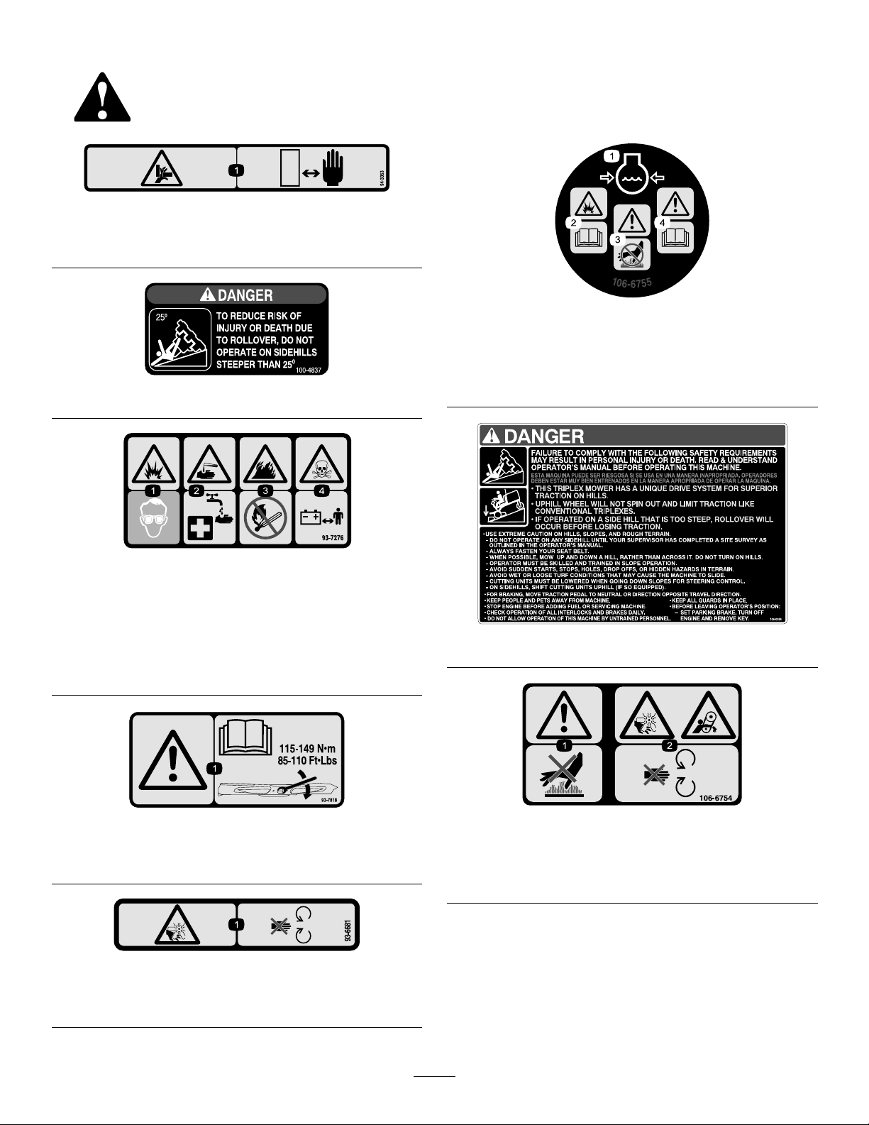
94-3353
1.Crushinghazardofhand—keepyourhandsasafedistance
away.
106-6755
100-4837
93-7276
1.Explosionhazard—weareyeprotection.
2.Causticliquid/chemicalburnhazard—toperformrstaid,
ushwithwater.
3.Firehazard—nore,openames,orsmoking.
4.Poisonhazard—keepchildrenasafedistancefromthe
battery.
1.Enginecoolantunder
pressure.
2.Explosionhazard—read
theOperator'sManual.
3.Warning—donottouchthe
hotsurface.
4.Warning—readthe
Operator'sManual.
104-0484
93-7818
1.Warning—readtheOperator'sManualforinstructionson
torquingthebladebolt/nutto85-110ft-lb(115-149N-m).
93-6681
1.Cutting/dismemberment—hazard,fan-stayawayfrom
movingparts.
106-6754
1.Warning—donottouchthehotsurface.
2.Cutting/dismembermenthazard,fanandentanglement
hazard,belt—stayawayfrommovingparts.
7
Page 8
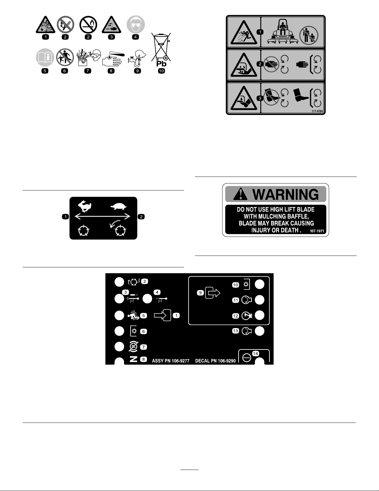
BatterySymbols
99-3444
Someorallofthesesymbolsareonyourbattery
1.Explosionhazard
2.Nore,opename,or
smoking.
3.Causticliquid/chemical
burnhazard
4.Weareyeprotection9.Flusheyesimmediately
5.ReadtheOperator's
Manual.
6.Keepbystandersasafe
7.Weareyeprotection;
8.Batteryacidcancause
10.Containslead;donot
99-3444
1.Transportspeed—fast
2.Mowingspeed—slow
distancefromthebattery.
explosivegasescan
causeblindnessandother
injuries
blindnessorsevereburns.
withwaterandgetmedical
helpfast.
discard.
117-4764
1.Thrownobjecthazard—keepbystandersasafedistance
fromthemachine.
2.Cuttinghazardofhand,mowerblade—stayawayfrom
movingparts,keepallguardsandshieldsinplace.
3.Cuttinghazardoffoot,mowerblade—stayawayfrom
movingparts,keepallguardsandshieldsinplace.
107–1971
1.Inputs5.Inseat
2.Notactive
3.High-temperature
shutdown
4.High-temperaturewarning8.Neutral
6.PowerTake-off(PTO)10.PowerTake-off(PTO)
7.ParkingbrakeOff11.Start
106-9290
9.Outputs13.Start
14.Power
12.EnergizetoRun(ETR)
8
Page 9
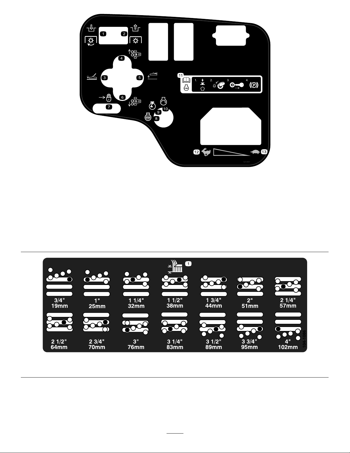
121–3531
1.EngagePTO6.Moveleft11.ReadtheOperator’sManualfor
2.DisengagePTO
3.Lowercuttingunit8.Engine—stop
4.Moveright9.Engine—run
5.Raisecuttingunit10.Engine—start
7.Lock12.Fast
informationonstoppingtheengine—
1)Disengagethereel;2)Movethekey
totheenginestopposition;3)Remove
thekeyfromtheignition;4)Engage
theparkingbrake.
13.Slow
1.Heightofcut
104-1086
9
Page 10
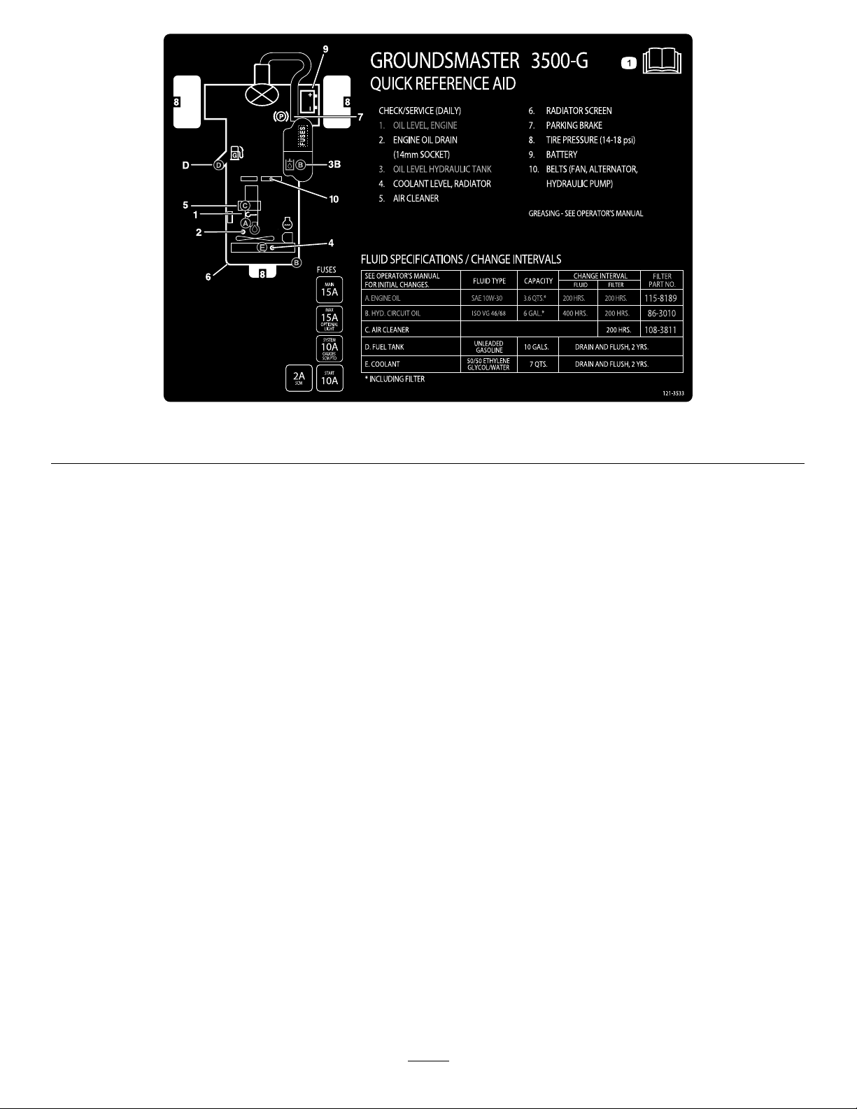
1.ReadtheOperator’sManualforinformationonmaintenance.
121–3533
10
Page 11

Setup
LooseParts
Usethechartbelowtoverifythatallpartshavebeenshipped.
ProcedureDescription
1
2
3
4
5
6
7
8
MediaandAdditionalParts
Description
Qty.
Nopartsrequired
Nopartsrequired
Nopartsrequired
Nopartsrequired
Nopartsrequired
Nopartsrequired
Nopartsrequired
Nopartsrequired
Qty.
–
–
–
–
–
–
–
–
Activate,charge,andconnectthe
battery.
Checktheangleindicator.
Adjusttheliftarms.
Adjustthecarrierframe.
Adjusttheheightofcut.
Checktheuidlevels.
Adjusttheoptionalrollerscraper.
Installtheoptionalmulchingbafe.
Use
Use
Ignitionkeys2
Operator'sManual
EngineOperator'sManual
PartsCatalog
Operatorvideo
Note:Determinetheleftandrightsidesofthemachinefromthenormaloperatingposition.
1
1
1Usetolookupandorderparts.
1
Starttheengine.
Readbeforeoperatingthemachine.
Viewbeforeoperatingthemachine.
11
Page 12
3.Removethellercapsfromthebatteryandslowlyll
eachcelluntilelectrolyteisjustabovetheplates.
1
Activating,Charging,and ConnectingtheBattery
NoPartsRequired
Procedure
WARNING
CALIFORNIA
Proposition65Warning
Batteryposts,terminals,andrelated
accessoriescontainleadandleadcompounds,
chemicalsknowntotheStateofCalifornia
tocausecancerandreproductiveharm.
W ash hands after handling .
Note:Ifthebatteryisnotlledwithelectrolyteoractivated,
bulkelectrolytewith1.260specicgravitymustbepurchased
fromalocalbatterysupplyoutletandaddedtothebattery.
DANGER
Batteryelectrolytecontainssulfuricacidwhichisa
deadlypoisonandcausessevereburns.
•Donotdrinkelectrolyteandavoidcontactwith
skin,eyes,orclothing.Wearsafetyglassesto
shieldyoureyesandrubberglovestoprotect
yourhands.
•Fillthebatterywherecleanwaterisalways
availableforushingtheskin.
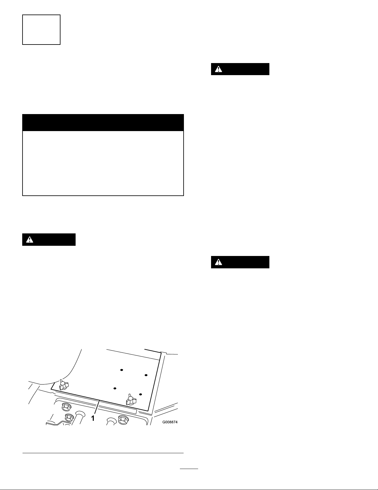
1.Openthehood.
2.Removethebatterycover(Figure3).
4.Installthellercapsandconnecta3to4ampbattery
chargertothebatteryposts.Chargethebatteryata
rateof3to4amperesfor4to8hours.
WARNING
Chargingthebatteryproducesgassesthatcan
explode.
•Keepsparksandamesawayfrombattery.
•Neversmokenearthebattery.
5.Whenthebatteryischarged,disconnectthecharger
fromtheelectricaloutletandbatteryposts.
6.Removethellercaps.Slowlyaddelectrolytetoeach
celluntilthelevelisuptothellring.Installtheller
caps.
Important:Donotoverllthebattery.Electrolyte
willoverowontootherpartsofthemachineand
severecorrosionanddeteriorationwillresult.
7.Installthepositivecable(red)tothepositive(+)
terminalandthenegativecable(black)tothenegative
(–)terminalofthebatteryandsecurethemwithbolts
andnuts(Figure4).Makesurethatthepositive(+)
terminalisallofthewayontothepostandthecable
ispositionedsnugtothebattery.Thecablemustnot
contactthebatterycover.
WARNING
Incorrectbatterycableroutingcoulddamage
thetractionunitandcablescausingsparks.
Sparkscancausethebatterygassesto
explode,resultinginpersonalinjury.
•Alwaysdisconnectthenegative(black)
batterycablebeforedisconnectingthe
positive(red)cable.
•Alwaysconnectthepositive(red)battery
cablebeforeconnectingthenegative
(black)cable.
1.Batterycover
Figure3
12
Page 13
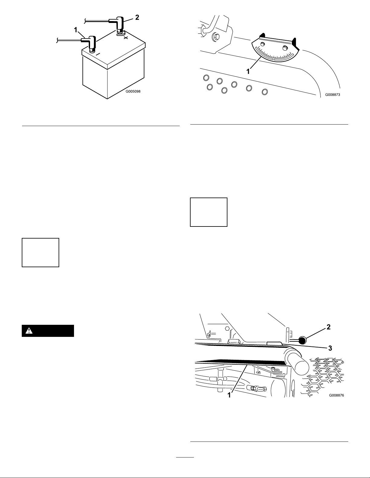
Figure4
1.Positive(+)batterycable2.Negative(–)batterycable
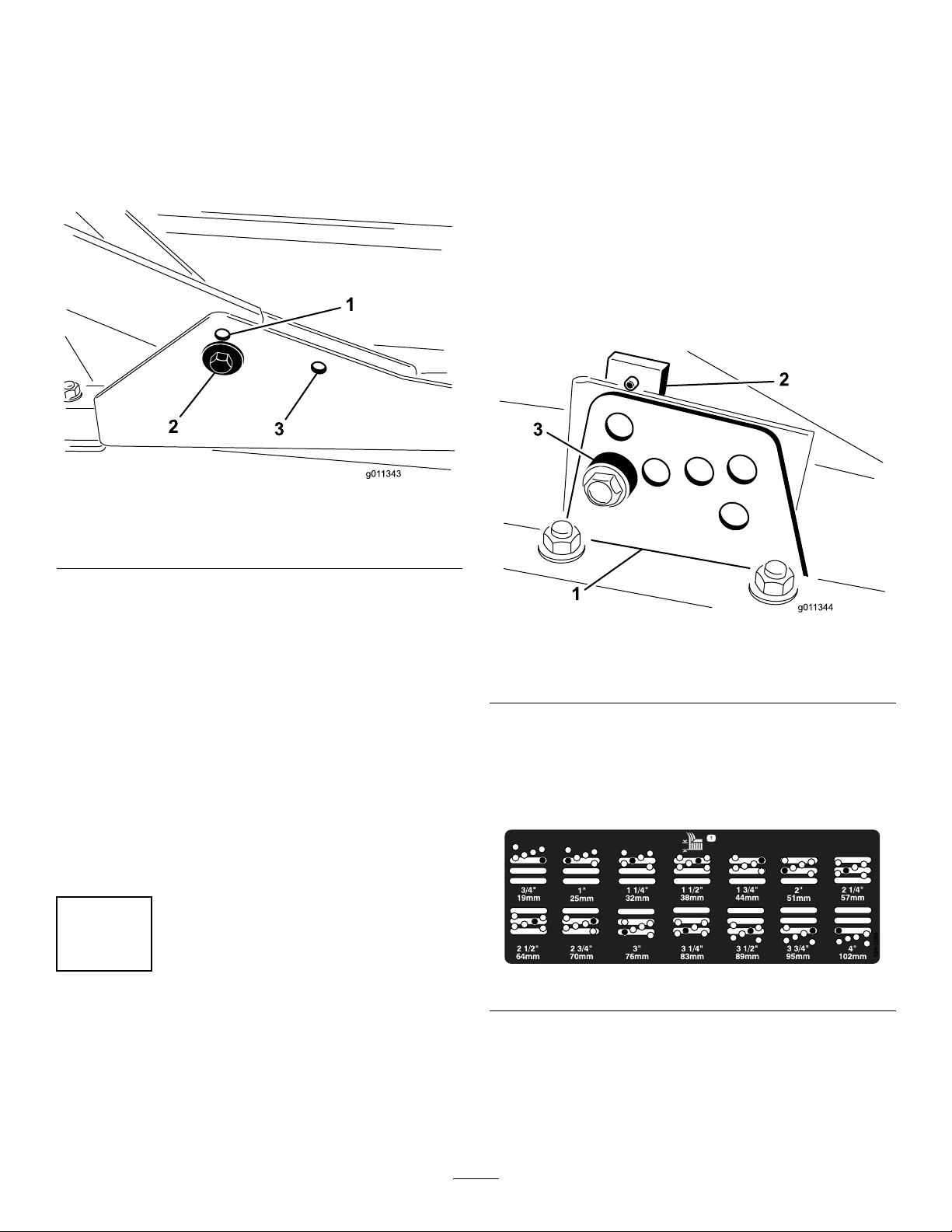
Figure5
1.Angleindicator
Important:Ifthebatteryiseverremoved,make
surethatthebatteryclampboltsareinstalledwith
theboltheadspositionedonthebottomsideand
thenutsonthetopside.Iftheclampboltsare
reversed,theymayinterferewiththehydraulic
tubeswhenshiftingthecutting-units.
8.CoatbothbatteryconnectionswithGrafo112X(skin
over)grease,T oroPartNo.505-47,petroleumjelly ,or
lightgreasetopreventcorrosion.
9.Slidetherubberbootoverthepositiveterminalto
preventapossibleshortfromoccurring.
10.Installthebatterycover.
2
CheckingtheAngleIndicator
NoPartsRequired
Procedure
3.Iftheinclinometerdoesnotreadzerodegrees,move
themachinetoalocationwhereazerodegreereading
isobtained.Theangleindicator,mountedonthe
machine,shouldnowreadzerodegreesaswell.
4.Iftheangleindicatordoesnotreadzerodegrees,loosen
the2screwsandnutssecuringtheangleindicatorto
themountingbracket,adjusttheindicatortoobtaina
zerodegreereading,andtightenthebolts.
3
AdjustingtheLiftArms
NoPartsRequired
Procedure
1.Starttheengine,raisethecutting-units,andcheckto
ensurethattheclearancebetweeneachliftarmandthe
oor-platebracketis5to8mm(0.18to0.32inch)as
showninFigure6.
DANGER
Donotoperatethemachineonsidehillssteeper
than25ºtoreduceriskofinjuryordeathdueto
rollover.
1.Parkthemachineonaat,levelsurface.
2.Verifythatthemachineislevelbyplacingahandheld
inclinometer(suppliedwiththemachine)ontheframe
crossrail,bythefueltank(Figure5).Theinclinometer
shouldreadzerodegreeswhenviewedfromthe
operator’sposition.
Figure6
cutting-unitsremovedforclarity
1.Liftarm3.Clearance
2.Floor-platebracket
13
Page 14
Iftheclearanceisnotinthisrange,adjustitasfollows:
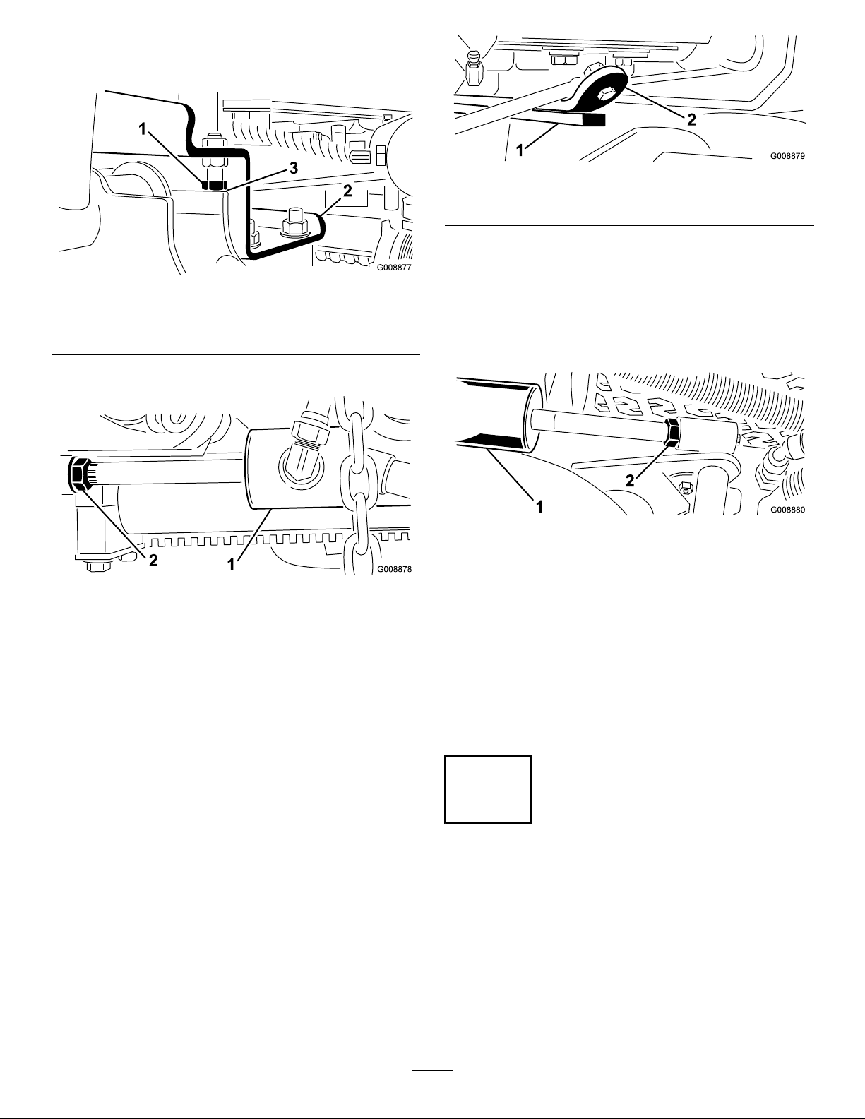
A.Backoffthestopbolts(Figure7).
Figure7
1.Stopbolt3.Clearance
2.Liftarm
B.Backoffthejamnutonthecylinder(Figure8).
Figure9
1.Wearbar2.Bumperstrap
Iftheclearanceisnotinthisrange,adjusttherear
cylinderasfollows:
Note:Iftherearliftarmclunksduringtransport,
clearancecanbereduced.
A.Lowerthecutting-unitsandbackoffthejamnut
onthecylinder(Figure10).
Figure8
1.Frontcylinder2.Jamnut
C.Removethepinfromtherodendandrotatethe
clevis.
D.Installthepinandchecktheclearance.Repeat
theprocedureifrequired.
E.Tightentheclevis-jamnut.
2.Checktomakesurethattheclearancebetweeneachlift
armandstopboltis0.13to1.02mm(0.005to0.040
inch)asshowninFigure7.Iftheclearanceisnotin
thisrange,adjustthestopboltstoattainclearance.
3.Starttheengine,raisethecuttingunits,andcheckto
makesurethattheclearancebetweenthewearstrap
onthetopoftherearcuttingunitwearbarandthe
bumperstrapis0.51to2.54mm(0.02to0.10inch)as
showninFigure9.
Figure10
1.Rearcylinder2.Adjustingnut
B.Graspthecylinderrodclosetothenutwitha
pliersandrag,androtatetherod.
C.Raisethecutting-unitsandchecktheclearance.
Repeattheprocedureifrequired.
D.Tightentheclevis-jamnut.
Important:Lackofclearanceatthefrontstopsorrear
wearbarcoulddamagetheliftarms.
4
AdjustingtheCarrierFrame
NoPartsRequired
AdjustingtheFrontCuttingUnit
Thefrontandrearcuttingunitsrequiredifferentmounting
positions.Thefrontcuttingunithas2mountingpositions
dependingonwhatheightofcutanddegreeofrotationyou
desire.
14
Page 15
1.Foraheightofcutinthe2to7.6cm(3/4to3inch)
range,mountthefrontcarrierframesinthelower,
frontmountingholes(Figure11).
samebenchsetting.Itmaybenecessarytohavethe
rotary-cuttingunitbenchset6mm(1/4inch)abovethat
ofareel-cuttingunitinthesamearea.
Note:Thispermitsmoreuptravelofthecuttingunit
relativetothetractionunitwhenapproachingquick
uphillchangesinterrain.Itdoeshoweverlimitthe
clearanceofthechambertothecarrierwhencresting
sharpknolls.
Figure11
1.Upper,frontmountinghole
2.Lower,frontmountinghole
3.Rearmountinghole
Important:Accesstotherear,cuttingunitsisgreatly
improvedbyremovingthecuttingunitfromthetraction
unit.IftheunitisequippedwithaSidewinder®,
sidewindthecuttingunitstotheright,removetherear
cuttingunit,andslideitouttotherightside.
1.Lowerthecuttingunittotheground,stoptheengine,
andremovethekeyfromtheignition.
2.Loosentheboltsecuringeachheightofcutbracketto
theheightofcutplate(frontandeachside)asshown
inFigure12.
3.Beginningwithfrontadjustment,removethebolt.
2.Foraheightofcutinthe6.3to10cm(2-1/2to4inch)
range,mountthefront,carrierframesintheupper,
frontmountingholes(Figure11).
Note:Thisincreasesthechamber-to-carrierclearance
duetothehigherpositionofthecuttingchamber,but
willcausethecuttingunittoreachtheirmaximumup
travelsooner.
AdjustingtheRear,CuttingUnit
Thefrontandrear,cuttingunitsrequiredifferentmounting
positions.Therearcuttingunithasonemountingposition
forproperalignmentwiththesidewinder-underframe.
Forallheightsofcut,mounttherearcuttingunitintherear
mountingholes(Figure11).
5
AdjustingtheHeightofCut
NoPartsRequired
Procedure
Figure12
1.Heightofcutbracket3.Spacer
2.Heightofcutplate
4.Whilesupportingthechamber,removethespacer
(Figure13).
5.Movethechambertothedesiredheightofcutand
installaspacerintothedesignatedheightofcuthole
andslot(Figure13).
Figure13
6.Positionthetappedplateinlinewiththespacer.
7.Hand-tightenthebolts.
8.Repeatsteps4-7foreachsideadjustment.
Important:Thiscuttingunitoftencutsapproximately
6mm(1/4inch)lowerthanareel-cuttingunitwiththe
9.Tightenall3boltsto41N-m(30ft-lb).Alwaystighten
thefrontboltrst.
15
Page 16
Note:Adjustmentsofmorethan3.8cm(1-1/2inch)
G011346
1
2
3
G011347
1
mayrequiretemporaryassemblytoanintermediate
heighttopreventbinding.
6
2.Slidethescraperupordownuntilagapof0.5to1
mm(0.020to0.040inch)isachievedbetweentherod
andtheroller.
3.Securethegreasettingandscrewto41N-m(30ft-lb)
inanalternatingsequence.
CheckingtheMachinebefore Operation
NoPartsRequired
Procedure
Performthefollowingcheckbeforeoperation:
•CheckingtheEngine-OilLevel(page19)
•CheckingtheCoolingSystem(page22)
•CheckingtheHydraulicSystem(page22)
•CheckingtheTirePressure(page23)
•TorquingtheWheelNuts(page40)
7
AdjustingtheOptionalRoller
8
InstallingtheOptional
MulchingBafe
NoPartsRequired
Procedure
1.Thoroughlycleandebrisfromthemountingholeson
therearandleft,sidewallsofthechamber.
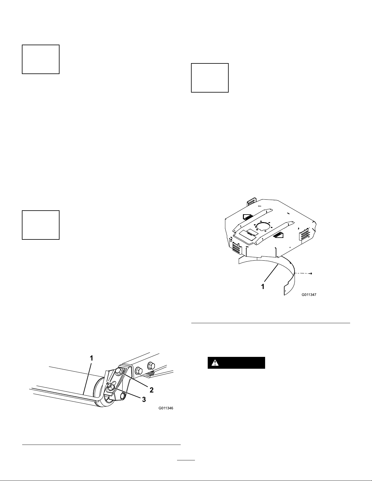
2.Installthemulchingbafeintherearopeningand
secureitwith5ange-headbolts(Figure15).
Scraper
NoPartsRequired
Procedure
Theoptionalrear-rollerscraperisdesignedtoworkbest
whenthereisanevengapof0.5to1mm(0.020–0.040inch)
betweenthescraperandroller.
1.Loosenthegreasettingandthemountingscrew
(Figure14).
Figure14
1.Rollerscraper
2.Mountingscrew
3.Greasetting
Figure15
1.Mulchingbafe
3.Verifythatmulchingbafedoesnotinterferewith
thetipofthebladeanddoesnotprotrudeinsidethe
surfaceoftherear,chamberwall.
WARNING
Donotusethehigh-liftbladewiththe
mulchingbafe.Thebladecouldbreak,
resultinginpersonalinjuryordeath.
16
Page 17

ProductOverview
g021539
Controls
Figure16
1.Forward-tractionpedal4.Tilt-steeringlever
2.Reverse-tractionpedal5.Indicatorslot
3.Mow/transportslide
6.Angleindicator
Tilt-SteeringLever
Pullthetilt-steeringlever(Figure16)backtotiltthesteering
wheeltothedesiredposition.Pushtheleverforwardtolock
thesteeringwheelintoposition.
IndicatorSlot
Theslotintheoperatorplatform(Figure16)indicateswhen
thecutting-unitsareinthecenterposition.
AngleIndicator
Theangleindicator(Figure16)indicatestheside-hillangleof
themachineindegrees.
IgnitionSwitch
Usetheignitionswitch(Figure18)isusedtostartandstop
theengine.The3positionsoftheswitchare;Off,On,and
Start.RotatethekeytotheStartpositiontostarttheengine.
Releasethekeywhentheenginestarts.Thekeyautomatically
movestotheOnpositionwhenyoureleaseit.Toshutthe
engineoff,rotatethekeytotheOffposition.Removethe
keyfromtheignitiontopreventsomeonefromstartingthe
machineunintentionally .
TractionPedals
Presstheforward-tractionpedal(Figure16)tomoveforward.
Pressthereverse-tractionpedal(Figure16)tomovebackward
ortoassistinstoppingwhenmovingforward.Tostopthe
tractionunit,movethepedalto,orallowittomoveto,the
neutralposition.
Mow/TransportSlide
UsingyourheeltomovetheMow/Transportslide(Figure
16)tothelefttotransport,andtotherighttomow .The
cutting-unitswillonlyoperateintheMowposition.
Note:Themowingspeedofthemachineissetatthefactory
to9.7km/h(6mph).Themowingspeedcanbeincreasedor
decreasedbyadjustingthespeed-stopscrew(Figure17).
Figure18
1.Throttle
2.Hourmeter
3.Temperaturelight9.Ignitionswitch
4.Oilpressurelight
5.Checkenginelight11.Liftleverlock
6.Alternatorlight
7.PTOswitch
8.Cutting-unitshiftlever
10.Parkingbrake
Throttle
1.Speed-stopscrew
Figure17
Movethethrottle(Figure18)forwardtoincreasetheengine
speedandrearwardtodecreasetheenginespeed.
PTOSwitch
ThePTOswitch(Figure18)has2positions:Out(start)and
In(stop).PullthePTOswitchouttoengagethecutting-unit
blades.Pushtheswitchintodisengagethecutting-unitblades.
17
Page 18

HourMeter
g021400
2
1
Lift-LeverLock
Thehourmeter(Figure18)indicatesthetotalhoursof
machineoperation.Thehourmeterstartstofunction
wheneverthekeyswitchisintheOnposition.
Cutting-UnitLever
Tolowerthecuttingunitstotheground,movethe
cutting-unitlever(Figure18)forward.Thecuttingunitswill
notdropunlesstheengineisrunning.Toraisethecutting
units,pulltheleverrearwardtotheRaiseposition.
Note:Theleverdoesnothavetobeheldintheforward
positionwhilethecuttingunitsarelowered.
Movethelevertotherightorleft,tomovethecuttingunits
totherightorleft.Thisshouldonlybedonewhenthe
cuttingunitsareraisedoriftheyareonthegroundandthe
machineismoving.
DANGER
Shiftthecuttingunitstotheuphillsideofthe
machinewhenonthesideofahill.
Usingthecuttingunitsonthedownhillsideofthe
machinecandecreasestability.Thiscouldcause
arollover,whichmayresultinpersonalinjuryor
death.
Coolant-TemperatureLight
Movethelift-leverlock(Figure18)rearwardtopreventthe
cuttingunitsfromdropping.
FuelGauge
Thefuelgauge(Figure19)indicatestheamountoffuelin
thefueltank.
Figure19
1.Seat-locklever
2.Fuelgauge
Thecoolant-temperaturelight(Figure18)willturnonifthe
coolanttemperatureraisesaboveasetlevel.Theenginewill
stopifthecoolanttemperatureraisesanother10°F .
Oil-PressureLight
Theoil-pressurelight(Figure18)willturnoniftheoil
pressuredropsbelowasetlevel.
AlternatorLight
Checkorrepairthechargingsystemifthealternatorlight
turnsonwhentheengineisrunning(Figure18).
Check-EngineLight
Checkorrepairtheengineifthecheck-enginelightturnson
whentheengineisrunning(Figure18).RefertotheService
Manualforpossiblecauses.
ParkingBrake
Engagetheparkingbrakewhenevertheengineisshutoff
(Figure18).Pulluponthelevertoengagetheparkingbrake.
AdjustingtheSeatForwardor
Backward
Movethelever(Figure19)onthesideoftheseatoutward
andslidetheseattothedesiredposition.Releasethelever
tolocktheseatintoposition.
Note:Theenginewillstopifyoupressthetractionpedal
withtheparkingbrakeengaged.
18
Page 19

Specications
G009027
1
2
Note:Specicationsanddesignaresubjecttochange
withoutnotice.
OverallWidth182cm(71.8inch)
WidthofCut173cm(68inch)
Length
HeighttotopofROPS180cm(70.8inch)
Wheelbase
295cm(1 16inch)
149cm(58.5inch)
Operation
Note:Determinetheleftandrightsidesofthemachine
fromthenormaloperatingposition.
ThinkSafetyFirst
Carefullyreadallsafetyinstructionsandsymbolsinthe
safetysection.Knowingthisinformationcouldhelpyouor
bystandersavoidinjury.
Trackwidth
Groundclearance15.3cm(6inch)
Weightwithcuttingunits
CuttingDeck
Length
Width
Height
34.9cm(13–3/4inch)at4
Weight
145cm(57inch)
963kg(2,124lb)
86.4cm(34inch)
86.4cm(34inch)
24.4cm(9.6inch)
tocarriermount
26.7cm(10–1/2inch)
at3/4inchheightofcut
inchesheightofcut
88kg(195lb)
Attachments/Accessories
Tobestprotectyourinvestmentandmaintainoptimal
performanceofyourToroequipment,countonTorogenuine
parts.Whenitcomestoreliability ,Torodeliversreplacement
partsdesignedtotheexactengineeringspecicationofour
equipment.Forpeaceofmind,insistonT orogenuineparts.
DANGER
Operatingonwetgrassorsteepslopescancause
slidingandlossofcontrol.
Wheelsdroppingoveredgescancauserollovers,
whichmayresultinseriousinjury,death,or
drowning.
Usetheseatbelt.
Readandfollowtherolloverprotectioninstructions
andwarnings.
Toavoidlossofcontrolandpossibilityofrollover:
•Donotoperateneardrop-offsornearwater.
•Donotoperateonslopesgreaterthan25º.
•Reducespeedanduseextremecautionon
slopes.
•Avoidsuddenturnsorrapidspeedchanges.
CAUTION
Thismachineproducessoundlevelsthatcancause
hearinglossthroughextendedperiodsofexposure.
Wearhearingprotectionwhenoperatingthis
machine.
Theuseofprotectiveequipmentforeyes,ears,hands,feet,
andheadisrecommended.
Figure20
1.Wearsafetyglasses.
2.Wearhearingprotection.
CheckingtheEngine-OilLevel
ServiceInterval:Beforeeachuseordaily
19
Page 20

Theengineisshippedwithoilinthecrankcase;however,the
G016095
g021401
2
oillevelmustbecheckedbeforeandaftertheengineisrst
started.
3.Iftheoillevelislow,removethellercap(Figure22)
andaddenoughoiltoraisethelevel-of-the-oiltothe
Fullmarkonthedipstick.
Crankcasecapacityisapproximately3.3L(3.5USqt)with
thelter.
Note:T oroPremiumEngineoilisavailablefromyour
distributorineither15W-40or10W-30viscosity.Seethe
partscatalogforpartnumbers.
Note:Thebesttimetochecktheengineoiliswhenthe
engineiscoolbeforeithasbeenstartedfortheday.Ifithas
alreadybeenrun,allowtheoiltodrainbackdowntothe
sumpforatleast10minutesbeforechecking.Iftheoillevelis
atorbelowtheAddmarkonthedipstick,addoiltobringthe
oilleveltotheFullmark.Donotoverll.Iftheoillevelis
betweentheFullandAddmarks,additionaloilisnotrequired.
Theengineusesanyhigh-quality10W -30detergentoilhaving
theAmericanPetroleumInstitute(API)serviceclassication
SJ,SK,SL,SM,orhigher.Chooseaviscosityaccordingto
thetableinFigure21.
Note:Whenaddingoil,removedipsticktoallow
properventing.Pouroilslowlyandcheckthe
level-of-the-oiloftenduringthisprocess.Donot
overll.
Important:Whenaddingengineoilorllingoil,
theremustbeclearancebetweentheoillldevice
andtheoilllholeinthevalvecoverasshownin
Figure23.Thisclearanceisnecessarytopermit
ventingwhenlling,whichpreventsoilfrom
overrunningintothebreather.
Figure21
1.Positionthemachineonalevelsurfaceandopenthe
hood.
2.Removethedipstick(Figure22)andwipeitwitha
cleanrag.Insertthedipstickintothetubeandmake
surethatitisseatedfully.Removedipstickandcheck
thelevel-of-the-oil.
Figure22
1.Dipstick2.Fillercap
Figure23
1.Noteclearance
4.Installthedipstickrmlyinplace.
5.Installtheoil-llcapandclosethehood.
FillingtheFuelTank
•Fueltankcapacity:38L(10USgallons)
•RecommendedFuel:
–Forbestresults,useonlyclean,fresh(lessthan30
daysold),unleadedgasolinewithanoctaneratingof
87orhigher((R+M)/2ratingmethod).
–Ethanol:Gasolinewithupto10%ethanol(gasohol)
or15%MTBE(methyltertiarybutylether)by
volumeisacceptable.EthanolandMTBEarenot
thesame.Gasolinewith15%ethanol(E15)by
volumeisnotapprovedforuse.Neverusegasoline
thatcontainsmorethan10%ethanolbyvolume,
suchasE15(contains15%ethanol),E20(contains
20%ethanol),orE85(containsupto85%ethanol).
Usingunapprovedgasolinemaycauseperformance
problemsand/orenginedamagewhichmaynotbe
coveredunderwarranty.
20
Page 21

–Donotusegasolinecontainingmethanol.
–Donotstorefueleitherinthefueltankorfuel
containersoverthewinterunlessafuelstabilizeris
used.
–Donotaddoiltogasoline.
DANGER
Incertainconditions,gasolineisextremely
ammableandhighlyexplosive.Areor
explosionfromgasolinecanburnyouand
othersandcandamageproperty.
Important:Donotusefueladditivesotherthanafuel
stabilizer/conditioner.Donotusefuelstabilizerswithan
alcoholbasesuchasethanol,methanol,orisopropanol.
1.Cleantheareaaroundthefuel-tankcap(Figure24).
2.Removethefuel-tankcap.
3.Fillthetanktothebottomofthellerneck.Donot
overll.Installthecap.
4.Topreventarehazard,wipeupanyfuelthatmay
havespilled.
Figure24
1.Fuel-tankcap
•Beforeremovingthefuel-tankcap,make
surethatthevehicleispositionedonalevel
surface.Openthefuel-tankcapslowly.
•Fillthefueltankoutdoors,inanopenarea,
whentheengineiscold.Wipeupany
gasolinethatspills.
•Neverllthefueltankinsideanenclosed
trailer.
•Donotllthefueltankcompletelyfull.
Addgasolinetothefueltankuntilthelevel
is6to13mm(1/4to1/2inch)belowthe
bottomofthellerneck.Thisemptyspace
inthetankallowsgasolinetoexpand.
•Neversmokewhenhandlinggasoline,and
stayawayfromanopenameorwhere
gasolinefumesmaybeignitedbyaspark.
•Storegasolineinanapprovedcontainer
andkeepitoutofthereachofchildren.
Neverbuymorethana30-daysupplyof
gasoline.
•Donotoperatewithoutentireexhaust
systeminplaceandinproperworking
condition.
21
Page 22

DANGER
Incertainconditionsduringfueling,static
electricitycanbereleasedcausingaspark
whichcanignitethegasolinevapors.Are
orexplosionfromgasolinecanburnyouand
othersandcandamageproperty.
•Alwaysplacethegasolinecontainerson
thegroundawayfromyourvehiclebefore
lling.
•Donotllthegasolinecontainersinsidea
vehicleoronatruckortrailerbedbecause
interiorcarpetsorplastictruckbedliners
mayinsulatethecontainerandslowthe
lossofanystaticcharge.
•Whenpractical,removegas-powered
equipmentfromthetruckortrailerand
refueltheequipmentwiththewheelson
theground.
•Ifthisisnotpossible,refuelsuch
equipmentonatruckortrailerfroma
portablecontainer,ratherthanfroma
gasolinedispensernozzle.
•Ifagasolinedispensernozzlemustbe
used,keepthenozzleincontactwiththe
rimofthefueltankorcontaineropeningat
alltimesuntilfuelingiscomplete.
Cleantheradiator/oilhourlyifconditionsareextremely
dustyordirty;refertoCleaningtheEngineCoolingSystem
(page41).
Thecoolingsystemislledwitha50/50solutionofwater
andpermanentethyleneglycolantifreeze.Checkthecoolant
levelatthebeginningofeachday,beforestartingtheengine.
CAUTION
Iftheenginehasbeenrunning,thepressurized-hot
coolantcanescapeandcauseburns.
•Donotopentheradiator-capwhentheengine
isrunning.
•Usearagtoopeningtheradiator-cap,andopen
thecapslowlytoallowthesteamtoescape.
1.Checkthecoolantlevelintheexpansiontank(Figure
26).Withacoldengine,thecoolantlevelshouldbe
approximatelymidwaybetweenthemarksontheside
ofthetank.
2.Ifthecoolantlevelislow,removetheexpansion-tank
capandreplenishthesystem.Donotoverll.
3.Installtheexpansion-tankcap.
CheckingtheCoolingSystem
ServiceInterval:Beforeeachuseordaily
Thecapacityofthecoolingsystemisapproximately5.7L
(6USqt).
Cleandebrisoffoftheradiator/oilcoolerdaily(Figure25).
Figure25
1.Radiator/Oilcooler
Figure26
1.Expansiontank
CheckingtheHydraulic System
ServiceInterval:Beforeeachuseordaily—Checkthe
hydraulicuidlevel.
Thetractionunitreservoirislledatthefactorywith
approximately22.7L(6USgallons)ofhigh-qualityhydraulic
uid.Checkthelevelofthehydraulicuidbefore
theengineisrststartedanddailythereafter.The
recommendedreplacementuidisToroPremiumAll
SeasonHydraulicFluidavailablein5-gallonpailsor
55-gallondrums.SeeyourAuthorizedToroDistributor.
22
Page 23

Alternateuids:IftheT orouidisnotavailable,youmay
useotheruidsprovidedthattheymeetallthefollowing
materialpropertiesandindustryspecications.Torodoes
notrecommendtheuseofsyntheticuid.Consultwithyour
lubricantdistributortoidentifyasatisfactoryproduct.Note:
Torowillnotassumeresponsibilityfordamagecausedby
impropersubstitutions,souseonlyproductsfromreputable
manufacturerswhowillstandbehindtheirrecommendation.
HighViscosityIndex/LowPourPointAnti-wearHydraulic
Fluid,ISOVG46
MaterialProperties:
Viscosity,ASTMD445cSt@40°C44to48
ViscosityIndexASTM
D2270
PourPoint,ASTMD97-34°Fto-49°F
IndustrySpecications:
VickersI-286-S(QualityLevel),VickersM-2950-S
(QualityLevel),DenisonHF-0
cSt@100°C7.9to8.5
140to160
PremiumBiodegradableHydraulicFluid-MobilEAL
EnviroSyn46H
Important:MobilEALEnviroSyn46Histheonly
syntheticbiodegradableuidapprovedbyT oro.This
uidiscompatiblewiththeelastomersusedinToro
hydraulicsystemsandissuitableforawide-range
oftemperatureconditions.Thisuidiscompatible
withconventionalmineraloils,butformaximum
biodegradabilityandperformancethehydraulicsystem
shouldbethoroughlyushedofconventionaluid.The
oilisavailablein5gallonpailsor55gallondrumsfrom
yourMobilDistributor.
Important:Manyhydraulicuidsarealmostcolorless,
makingitdifculttospotleaks.Areddyeadditivefor
thehydraulicsystemoilisavailablein20ml(2/3oz)
bottles.Onebottleissufcientfor15to22L(4to6
gallons)ofhydraulicoil.Orderpartno.44-2500from
yourauthorizedT orodistributor.
Figure27
1.Hydraulictankcap
3.Removethedipstickfromthellerneckandwipeit
withacleanrag.
4.Insertthedipstickintothellerneck,thenremoveit
andchecktheuidlevel.
Note:Theuidlevelshouldbewithinthemarkson
thedipstick.
5.Ifthelevelislow ,addtheappropriateamountofuid
toraisetheleveltothefullmark.
6.Installthedipstickandcapontothellerneck.
CheckingtheTirePressure
ServiceInterval:Beforeeachuseordaily
Thetiresareover-inatedforshipping.Therefore,release
someoftheairtoreducethepressure.Thecorrectair
pressureinthetiresis97to124kPa(14to18psi).
Note:Maintaintherecommendedpressureinalltiresto
ensureagoodqualityofcutandpropermachineperformance.
1.Positionthemachineonalevelsurface,lowerthe
cuttingunits,andstoptheengine.
2.Cleantheareaaroundthellerneckandcapofthe
hydraulictank(Figure27).Removethecap.
DANGER
Lowtirepressuredecreasesmachinesidehill
stability.Thiscancausearollover,whichcanresult
inpersonalinjuryordeath.
Donotunder-inatethetires.
RearWheelBallast
ThemachineconformstoANSIstandardB71.4-2012
standardwhen22.6kg(50lb)ofcalcium-chlorideballastis
addedtotherearwheels.
Important:Ifapunctureoccursinatirecontaining
calciumchloride,removethemachinefromtheturfas
quicklyaspossible.Immediatelysoaktheaffectedarea
withwatertopreventpossibledamagetotheturf.
23
Page 24

StartingandStoppingthe
CheckingtheInterlockSystem
Engine
StartingtheEngine
1.Besurethattheparkingbrakeissetandthecutting
unitdriveswitchisintheDisengageposition.
2.Removeyourfootfromthetractionpedalandmake
surethatthepedalisintheNeutralposition.
3.Movethethrottlelevertothe1/2throttleposition.
4.InsertthekeyintotheswitchandrotateittotheStart
positiontoengagethestartermotor.
Note:Releasethekeywhentheenginestarts.Thekey
movesautomaticallytotheOn/Runposition.
Important:T opreventoverheatingofthestartermotor,
donotengagethestarterlongerthan15seconds.After
15secondsofcontinuouscranking,wait60seconds
beforeengagingthestartermotoragain.
StoppingtheEngine
1.MovethethrottlecontroltotheIdleposition.
ServiceInterval:Beforeeachuseordaily
1.Makesurethatallbystandersareawayfromthearea
ofoperation.
Note:Keephandsandfeetawayfromthecutting
units.
Note:Whilesittingontheseat,theenginemustnot
startwitheitherthecutting-unitswitchengagedorthe
tractionpedalengaged.Correcttheproblemifitisnot
operatingproperly.
2.Whilesittingontheseat,putthetractionpedalinthe
Neutralposition,theparkingbrakeintheOffposition,
andthecutting-unitswitchintheOffposition.
Note:Theengineshouldstart.
3.Risefromtheseatandslowlypressthetractionpedal.
Note:Theengineshouldstopin1to3seconds.
Correcttheproblemifitisnotoperatingproperly.
Note:Theenginestopswhenyoupressthetractionpedal
andengagetheparkingbrake.
2.Movethecutting-unitdriveswitchtoDisengage.
3.RotatethestarterkeytoOff.
4.Removethekeyfromtheignitionswitch.
TowingtheTractionUnit
Incaseofanemergency ,themachinecanbetowedfora
shortdistance.
Important:Donottowthemachinefasterthan3to
4km/h(2to3mph)becausethedrivesystemmay
becomedamaged.Ifthemachinemustbemoveda
considerabledistance,transportitonatruckortrailer.
1.Locatethebypassvalveonthepump(Figure28)and
rotateit90°.
Figure28
1.Bypassvalve
2.Beforestartingtheengine,closethebypassvalveby
rotatingit90°(1/4turn).
Note:Donotstarttheenginewhenthevalveisopen.
24
Page 25

StandardControlModule (SCM)
TheStandardControlModuleisapottedelectronicdevice
producedinaonesizetsallconguration.Themodule
usessolidstateandmechanicalcomponentstomonitorand
controlstandardelectricalfeaturesrequiredforsafeproduct
operation.
Themodulemonitorsinputsincludingneutral,parkingbrake,
PTO,start,backlap,andhightemperature.Themodule
energizesoutputsincludingPTO,Starter,andETR(energize
torun)solenoid.
Themoduleisdividedintoinputsandoutputs.Inputsand
outputsareidentiedbygreenLEDindicators.
circuitisenergized.UsetheinputLEDstotroubleshoot
switchesandinputcircuits.
Outputcircuitsareenergizedbyanappropriatesetofinput
conditions.The3outputsarePTO,ETR,andSTART.The
outputLEDindicatesthepresenceofvoltageattherelay .
Outputcircuitsdonotdeterminetheintegrityoftheoutput
device.Troubleshootingtheelectricalintegrityofanoutput
circuitshouldincludetheoutputLED ,thedevice,andthe
wiringharness.Measuredisconnectedcomponentimpedance,
impedancethroughthewiringharness(disconnectatSCM),
orbytemporarily”testenergizing”thespeciccomponent.
TheSCMdoesnotconnecttoanexternalcomputeror
hand-helddevice,itcannotbere–programmed,anditdoes
notrecordintermittentfaulttroubleshootingdata.
Thestartcircuitinputisenergizedby12VDC.Allother
inputsareenergizedwhenthecircuitisclosedtoground.
EachinputhasanLEDthatisilluminatedwhenthespecic
Figure29
HerearethelogicaltroubleshootingstepsfortheSCMdevice.
1.Determinetheoutputfaultyouaretryingtoresolve
(PTO,START,orETR).
2.MovekeyswitchtotheOnpositionandensurethat
theredpowerLEDisilluminated.
3.MoveallinputswitchestoensureallLEDschange
state.
4.Positioninputdevicesatappropriatepositionto
achievetheappropriateoutput.Usethefollowinglogic
charttodeterminetheappropriateinputcondition.
5.IfspecicoutputLEDisilluminatedwithout
appropriateoutputfunction,checktheoutputharness,
theconnections,andthecomponent.Repairas
required.
6.IfspecicoutputLEDisnotilluminated,checkboth
ofthefuses.
ThedecalontheSCMonlyincludessymbols.Thereare3
LEDoutputsymbolsareshownintheoutputbox.Allother
LEDsareinputs.Thechart(Figure29)identiesthesymbols.
7.IfspecicoutputLEDisnotilluminatedandthe
inputsareinanappropriatecondition,installanew
SCManddetermineifthefaultdisappears.
Eachrowinthelogicchartbelowidentiestheinputand
outputrequirementsforeachspecicfunction.Thefunctions
arelistedintheleftcolumn.Thesymbolsidentifyspecic
circuitconditionincluding:energizedtovoltage,closedto
ground,andopentoground.
•(–)Indicatesacircuitclosedtoground.–LEDON
•(O)Indicatesacircuitopentogroundorde–energized
–LEDOFF
•(+)Indicatesanenergizedcircuit(clutchcoil,solenoid,or
startinput)LEDON.
•ABlankindicatesacircuitthatisnotinvolvedwiththe
logic.
25
Page 26

INPUTSOUTPUTS
FunctionPower
Start
Run(Off
Unit)
Run(On
Unit)
Mow
Backlap
HiTemp
ON
——
——
—
—
——
—
In
Neutral
OO
OO
StartON
+
OOOOOOO
OO
O
Brake
ON
OO
—
———
Totroubleshoot,turnthekeytotheOnposition.Identify
thespecicfunctionthatisnotoperatingproperlyandwork
acrossthelogicchart.Inspecttheconditionofeachofthe
inputLEDstoensureitmatchesthelogicchart.
IftheinputLEDsarecorrect,checktheoutputLEDs.Ifthe
outputLEDsareilluminatedbutthedeviceisnotenergized,
measuretheavailablevoltageattheoutputdevice,continuity
ofthedisconnecteddevice,andpotentialvoltageonthe
groundcircuit(oatingground).Repairswillvarydepending
onyourndings.
PTOONInSeat
O
—
—
—
OO
HiTempBacklap
OO
OOO
OOO
—
—
Start
++
O
OOO
ETR
+
+
++
++
PTO
O
O
O
26
Page 27

ChoosingAccessories
OptionalEquipmentCongurations
AngleSailBladeHighLiftParallel
HeightofCut
1.9to4.4cm(0.75
to1.75inches)
HeightofCut
5to6.4cm(2.00to
2.50inches)
HeightofCut
7to10cm(2.75to
4.00inches)
LeafMulchingRecommendedforuse
ProsEvendischargeat
ConsDoesnotliftthe
Recommendedinmost
applications
Recommendedforthick
orlushturf
Mayworkwellinlushturf
withthemulchingbafe
alowheightofcut
Cleanerlookaround
bunkersandfairways
Lowerpower
requirements
grasswellata
highheightofcut
Wetorstickygrass
hasatendencytobuild
upinthechamber,
leadingtopoorquality
ofcutandhigherpower
requirements
SailBlade
Donotusewiththe
mulchingbafe
Mayworkwellinlightor
sparseturf
Recommendedforlight
orsparseturf
Recommendedinmost
applications
NotAllowedUsewithcombination
Moreliftandhigher
dischargevelocity
Sparseorlimpturf
ispickedupata
highheightofcut
Wetorstickyclippings
aredischargedefciently
Requiresmorepowerto
runinsomeapplications
Tendstowindrow
atalowheightof
cutinlushgrass
Donotusewiththe
mulchingbafe
MulchingBafeRollerScraper
Hasbeenshownto
improvedispersionand
aftercutperformance
onnortherngrassesthat
arecutatleastthree
timesperweekand
whenlessthan1/3ofthe
grassbladeisremoved
Donotusewiththe
highliftparallelsail
blade
sailoranglesailblade
only
Mayimprovedispersion
andappearance
incertaingrass
cuttingapplications
Verygoodforleaf
mulching
Grasswillbuildupinthe
chamberifattemptingto
removetoomuchgrass
withbafeinplace
Canbeusedanytime
thatrollersbuildup
withgrassorlargeat
grassclumpsareseen
Thescrapersmay
actuallyincrease
clumpingincertain
applications
Reducesrollerbuildup
incertainapplications
SelectingaBlade
StandardCombinationSail
Thisbladewasdesignedtoprovideexcellentliftand
dispersioninalmostanycondition.Ifmoreorlessliftand
dischargevelocityisrequired,consideradifferentblade.
Attributes:Excellentliftanddispersioninmostconditions.
AngledSail
Thebladegenerallyperformsbestatalowerheightofcut,
1.9to6.4cm(3/4to2–1/2inches).
Attributes:
•Dischargeremainsmoreevenlyatalowerheightofcut.
•Dischargehaslesstendencytothrowleftandthusa
cleanerlookaroundbunkersandfairways.
•Lowerpowerrequirementatalowerheightofcutin
denseturf.
HighLiftParallelSail
Thebladegenerallyperformsbetteratahigherheightofcut,
7to10cm(2to4inches).
Attributes:
•Moreliftandhigherdischargevelocity.
•Sparseorlimpturfispickedupsignicantlyatahigher
heightofcut.
•Wetorstickyclippingsaredischargedmoreefciently,
reducingcongestioninthedeck.
27
Page 28

•Requiresmorehorsepowertorun.
•Tendstodischargefurtherleftandcantendtowindrow
atalowerheightofcut.
WARNING
Donotusethehigh-liftbladewiththemulching
bafe.Thebladecouldbreak,resultinginpersonal
injuryordeath.
AtomicBlade
Thisbladewasdesignedtoprovideexcellentleafmulching.
Attributes:Excellentleafmulching
OperatingTips
GeneralTips
•Practiceoperatingthemachineandbecomethoroughly
familiarwithit.
•Starttheengineandrunitathalfidleuntilitwarmsup.
Pushthethrottleleverallthewayforward,liftthecutting
units,disengagetheparkingbrake,presstheforward
tractionpedal,andcarefullydrivetoanopenarea.
•Practicemovingforwardandreverse,andstartingand
stoppingthemachine.Tostop,takeyourfootoffthe
tractionpedalandletitreturntoneutralorpressdown
onthereversepedaltostop.Goingdownahill,youmay
needtousethereversepedaltostop.
•Whendrivingonslopes,driveslowlytomaintainsteering
controlandavoidturnstopreventrollovers.Inside
hillsituations,shiftthesidewindercuttingunitstothe
uphillsidetogiveyoumorestability .Conversely,shifting
thecuttingunitstothedownhillsidewillgiveyouless
stability.Thisshouldalwaysbedonebeforegoingona
sidehill.
•Whenpossible,mowupanddownhillsratherthanacross
them.Havethecuttingunitsloweredwhengoingdowna
hilltomaintainsteeringcontrol.Donotattempttoturn
onahill.
•Practicedrivingaroundobstacleswiththecuttingunits
upanddown.Becarefulwhendrivingbetweennarrow
objectssoyoudonotdamagethemachineorthecutting
units.
•OntheSidewinderunit,getafeelforthereachofthe
cuttingunitssothatyoudonothangthemupordamage
theminanyway.
•Donotshiftthecuttingunitsfromsidetoside,unlessthe
cuttingunitsaredownandthemachineismoving,orthe
cuttingunitsareupinthetransportposition.Shiftingthe
cuttingunitswhentheyaredownandthemachineisnot
movingmaycauseturfdamage.
•Alwaysdriveslowlyinroughareas.
•Ifapersonappearsinorneartheoperatingarea,stopthe
machine,anddonotstartitagainuntiltheareaiscleared.
Themachineisdesignedfor1person.Neverletanyone
elserideonthemachinewithyou.Thisisextremely
dangerousandcouldresultinseriousinjury.
•Accidentscanhappentoanyone.Themostcommon
causesareexcessivespeed,suddenturns,terrain(not
knowingwhichslopesandhillscanbemowedsafely),not
stoppingtheenginebeforeleavingtheoperator’sseat,
anddrugs,whichimpairyouralertness.Coldcapsulesor
prescriptiondrugsmaycausedrowsiness,ascanalcohol
andotherdrugs.Stayalertandstaysafe.Failuretodoso
couldresultinseriousinjury.
•TheSidewinderoffersuptoamaximumof33cm(13
inch)ofoverhang,allowingyoutotrimclosertotheedge
ofsandtrapsandotherobstacles,whileatthesametime
keepingthetiresasfarawayfromtheedgeoftrapsor
waterhazardsaspossible.
•Ifanobstacleisintheway ,shiftthecuttingunitstoeasily
mowaroundit.
•Whendrivingthemachinefromoneworkareatoanother,
raisethecuttingunitstothefully-upposition,movethe
Mow/TransportslidetothelefttoTransport,andplace
thethrottletotheFastposition.
MowingPatterns
Changemowingpatternsoftentominimizeaftercut
appearanceissuesthatareinducedbyrepetitivemowingin
onlyonedirection.
Counterbalance
Thecounterbalancesystemmaintainshydraulicbackpressure
onthecuttingunitliftcylinders.Thiscounterbalancepressure
transferscutting-unitweighttothetraction-unitdrivewheels
toimprovetraction.Thecounterbalancepressurehasbeen
factorysettoanoptimalbalanceofaftercutappearanceand
tractioncapabilityinmostturfconditions.Decreasingthe
counterbalancesettingcanproduceamorestablecutting
unit,butcandecreasethetractioncapability .Increasingthe
counterbalancesettingcanincreasethetractioncapability,
butmayresultinaftercutappearanceissues.Referencethe
servicemanualforyourtractionunitforinstructionstoadjust
counterbalancepressure.
ResolvingAftercutAppearance
ReferencetheAftercutAppearanceTroubleshootingGuide
availableatwww .Toro.com
MowingTechniques
•Tobegincutting,engagethecuttingunits,thenapproach
themowingareaslowly.Oncethefrontcuttingunitsare
overthemowingarea,lowerthecuttingunits.
•Toachievetheprofessionalstraight-linecutandstriping
thatisdesirableforsomeapplications,ndatreeorother
objectinthedistanceanddrivestraighttowardit.
28
Page 29

•Assoonasthefrontcuttingunitsreachtheedgeof
themowingarea,liftthecuttingunitsandperforma
teardrop-shapedturntoquicklylineyouupforyournext
pass.
•Tomowaroundbunkers,ponds,orothercontours
easily,usetheSidewinderandmovethecontrolleverleft
orright,dependingonyourmowingapplication.The
cuttingunitscanalsobeshiftedtovarytiretracking.
•Thecuttingunitstendtothrowgrasstotheleftside
ofthemachine.Iftrimmingaroundbunkers,itisbest
tomowinaclockwisedirectiontopreventthrowing
clippingsintothebunker.
•Thecuttingunitscanbeequippedwithbolt-inmulching
bafes.Themulchingbafesperformwellwhenturfis
maintainedonaregularscheduletoavoidremovingmore
than25mm(1inch)ofgrowthpercutting.Whentoo
muchgrowthiscutwiththemulchingbafesinstalled,
aftercutappearancemaydeteriorateandtheobserved
powertocuttheturfincreases.Themulchingbafesalso
performwellforshreddingleavesinthefall.
MowWhenGrassIsDry
keptfreeofdirtorgrassclippings.Aftercleaning,inspectthe
machineforpossiblehydraulic-uidleaks,damage,orwear
tothehydraulicandmechanicalcomponents,andcheckthe
cutting-unitbladesforsharpness.
Important:Afterwashingthemachine,movethe
Sidewindermechanismfromlefttorightseveraltimesto
removewaterbetweenthebearingblocksandcrosstube.
Moweitherinthelatemorningtoavoidthedew,which
causesgrassclumping,orinlateafternoontoavoidthe
damagethatcanbecausedbydirectsunlightonthesensitive,
freshlycutgrass.
SelecttheProperHeightofCutSetting
toSuitConditions
Removeapproximately25mm(1inch)ornomorethan1/3
ofthegrassbladewhencutting.Inexceptionallylushand
densegrass,youmayhavetoraiseyourheightofcutsetting
toahighersetting.
AlwaysStartMowingwithSharpBlades
Asharpbladecutscleanlyandwithouttearingorshredding
thegrassbladeslikeadullblade.Tearingandshredding
causesthegrasstoturnbrownattheedgeswhichimpairs
growthandincreasessusceptibilitytodiseases.Makesurethat
thebladeisingoodconditionandafullsailispresent.
CheckConditionofCuttingUnit
Makesurethatcuttingchambersareingoodcondition.
Straightenanybendsinchambercomponentstoensure
correctbladetip/chamberclearance.
AfterMowing
Atthecompletionofmowingoperation,thoroughlywashthe
machinewithagardenhosewithoutanozzlesothatexcessive
waterpressurewillnotcontaminateanddamagetheseals
andbearings.Makesurethattheradiatorandoilcoolerare
29
Page 30

Maintenance
Note:Determinetheleftandrightsidesofthemachine
fromthenormaloperatingposition.
RecommendedMaintenanceSchedule(s)
MaintenanceService
Interval
Afterthersthour
Aftertherst8hours
Aftertherst10hours
Aftertherst50hours
Beforeeachuseordaily
Every25hours
Every50hours
Every200hours
MaintenanceProcedure
•Torquethewheelnuts.
•Checktheconditionandtensionofallbelts.
•Torquethewheelnuts.
•Changethehydrauliclter.
•Changetheoilandoillter.
•Checktheengineoillevel.
•Checktheenginecoolantlevel.
•Checkthehydraulicuidlevel.
•Checkthetirepressure.
•Checktheinterlocksystem.
•Cleandebrisoffoftheradiatorandoilcooler.
•Checkthehydrauliclinesandhoses.
•Checktheblade-stoppingtime.
•Checktheelectrolytelevel.(Ifmachineisinstorage,checkevery30days.)
•Lubricateallbearingsandbushings.(Lubricateallbearingsandbushingsdaily
whenconditionsaredustyanddirty.)
•ServicetheAirCleaner(Morefrequentlyinextremedustyordirtyconditions)
•Changetheoilandoillter.
•Torquethewheelnuts.
•Checktheparkingbrakeadjustment.
•Checktheconditionandtensionofallbelts.
•Changethehydrauliclter.
•Replacethesparkplugs.
Every400hours
Every500hours
Every2years
•Replacethefuel-pumplter.
•Checkthefuellinesandconnections.
•Changethehydraulicuid.
•Greasethebearingsintherearaxle.
•Drainandcleanthefueltank.
•Flushthecoolingsystemandreplaceuid.
CAUTION
Ifyouleavethekeyintheignitionswitch,someonecouldaccidentlystarttheengineandseriouslyinjure
youorotherbystanders.
Removethekeyfromtheignitionbeforeyoudoanymaintenance.
30
Page 31

DailyMaintenanceChecklist
Duplicatethispageforroutineuse.
Fortheweekof:
MaintenanceCheckItem
Checkthesafetyinterlock
operation.
Checkthebrakeoperation.
Checktheengineoillevel.
Checkthecoolingsystem
uidlevel.
Checktheairlter,dustcup,
andburpvalve.
Checkforunusualengine
2
noises.
Checktheradiatorand
screenfordebris.
Checkforunusualoperating
noises.
Checkthehydraulicsystem
oillevel.
Checkthehydraulichoses
fordamage.
Checkforuidleaks.
Checkthefuellevel.
Checkthetirepressure.
Checktheinstrument
operation.
Checktheheightofcut
adjustment.
Lubricateallthegrease
2
ttings.
Touch-upanydamaged
paint.
1
Checktheglowplugandinjectornozzlesifstartingishard,thereisexcesssmoke,orroughrunningisnoted.
2
Immediatelyaftereverywashing,regardlessoftheintervallisted.
Mon.T ues.Wed.Thurs.Fri.
Sat.Sun.
Important:Refertoyourengine
Operator's Man ual
foradditionalmaintenanceprocedures.
Note:LookingforanElectricalSchematicorHydraulicSchematicforyourmachine?Downloadafreecopyoftheschematicby
visitingwww .T oro.comandsearchingforyourmachinefromtheManualslinkonthehomepage.
NotationforAreasofConcern
Inspectionperformedby:
ItemDate
31
Information
Page 32

ServiceIntervalChart
Premaintenance
Procedures
RemovingtheHood
Thehoodmaybeeasilyremovedtoeasemaintenance
proceduresintheengineareaofthemachine.
1.Unlatchandraisethehood.
2.Removethehairpincottersecuringthehoodpivotto
themountingbrackets(Figure31).
Figure30
Figure31
1.Hairpincotter
3.Slidethehoodtotherightside,lifttheotherside,and
pullitoutofthebrackets.
Note:Reversetheproceduretoinstallthehood.
32
Page 33

UsingtheCutting-UnitService Latch
Lubrication
Whenservicingthecuttingunits,usetheservicelatchto
preventinjury.
1.Centerthecuttingunitsidewinderwiththetraction
unit.
2.Raisethecuttingunitstothetransportposition.
3.Settheparkingbrakeandturnoffthemachine.
4.Releasethelatchrod(Figure32)fromthefrontcarrier
frameretainer.
Figure32
1.Latchhook
GreasingtheBearingsAnd Bushings
ServiceInterval:Every50hours(Lubricateallbearingsand
bushingsdailywhenconditionsaredusty
anddirty.)
Every500hours/Yearly(whichevercomesrst)
LubricategreasettingsregularlywithNumber2
general-purpose,lithium-basedgrease.Lubricatethebearings
andbushingsdailywhenoperatingconditionsareextremely
dustyordirty.Dustyordirtyoperatingconditionscould
causedebristogetintothebearingsandbushings,resultingin
acceleratedwear.Lubricategreasettingsimmediatelyafter
everywashing,regardlessofintervalspecied.
Thegreasettinglocationsandquantitiesareasfollows:
•Rearcuttingunitpivot(Figure33)
5.Lifttheoutsideofthefrontcuttingunitsandplacethe
latchovertheframepinmountedonthefrontofthe
operator'splatform(Figure32).
6.Sitontheoperatorseatandstartthemachine.
7.Lowerthecuttingunitstothemowposition.
8.Turnoffthemachineandremovethekeyfromthe
ignition.
9.Reversethisproceduretounlatchthecuttingunits.
Figure33
•Frontcuttingunitpivot(Figure34)
Figure34
33
Page 34

•SideWindercylinderends2(Figure35)
Figure35
•Steeringpivot(Figure36)
•Rearlift-armpivotandliftcylinder2(Figure37)
Figure37
•Leftfrontlift-armpivotandliftcylinder2(Figure38)
Figure36
Figure38
•Rightfrontlift-armpivotandliftcylinder2(Figure39)
Figure39
•Neutral-adjustmechanism(Figure40)
34
Page 35

Figure40
•Steeringcylinder(Figure43).
•Mow/Transportslide(Figure41)
Figure41
•Belt-tensionpivot(Figure42)
Figure43
Note:Ifdesired,installanadditionalgreasettingin
theotherendofthesteeringcylinder.Removethetire,
installthetting,greasethetting,removethetting,and
installtheplug(Figure44).
Figure44
•Cuttingunitspindle-shaftbearings(2percuttingunit)
(Figure45)
Figure42
Note:Eitherttingcanbeused,whicheverismore
accessible.Pumpgreaseintothettinguntilasmall
amountappearsatbottomofthespindlehousing(under
thecuttingunit).
Figure45
35
Page 36

•Rearrollerbearings(2percuttingunit)(Figure46)
G011349
Figure46
Note:Makesurethatthegreasegrooveineachroller
mountalignswiththegreaseholeineachendoftheroller
shaft.Tohelpalignthegrooveandhole,thereisalsoan
alignmentmarkon1endoftherollershaft.
EngineMaintenance
ServicingtheAirCleaner
ServiceInterval:Every200hours(Morefrequentlyin
extremedustyordirtyconditions)
Inspecttheaircleanerandhosesperiodicallytomaintain
maximumengineprotectionandtoensuremaximumservice
life.Checktheair-cleanerbodyfordamage,whichcould
causeanairleak.Replaceadamagedair-cleanerbody.
Inspectandchangetheair-cleanerlterasdescribedinthe
followingprocedure:
1.Pullthelatchoutwardandrotatetheair-cleanercover
counterclockwise.
Figure47
1.Air-cleanercover2.Filter
2.Beforeremovingthelter,uselow-pressureair(40psi,
cleananddry)tohelpremovelargeaccumulationsof
debrispackedbetweentheoutsideoftheprimarylter
andthecanister.
Important:Avoidusinghigh-pressureairwhich
couldforcedirtthroughthelterintotheintake
tract.Thiscleaningprocesspreventsdebrisfrom
migratingintotheintakewhenyouremovethe
primarylter.
3.Removeandreplacetheprimarylter.
Note:Cleaningoftheusedelementisnot
recommendedduetothepossibilityofdamagetothe
ltermedia.
4.Inspectthenewlterforshippingdamage,checking
thesealingendofthelterandthebody.
Important:Donotuseadamagedlter.
5.Insertthenewlterbyapplyingpressuretotheouter
rimoftheelementtoseatitinthecanister.
36
Page 37

6.Cleanthedirtejectionportlocatedintheremovable
g021403
1
g021414
1
cover.Removetherubberoutletvalvefromthecover,
cleanthecavity,andreplacetheoutletvalve.
7.Installthecoverorientingtherubber,outletvalveina
downwardposition,betweenapproximately5o'clock
to7o'clockwhenviewedfromtheend(Figure47).
8.Securethecoverlatches.
ChangingtheEngineOiland Filter
ServiceInterval:Aftertherst50hours
Every200hours
1.Removethedrainplug(Figure48)andletoilow
intoadrainpan.Whentheoilstopsowing,install
thedrainplug.
Figure49
1.Engineoillter
3.Addoiltothecrankcase;refertoCheckingthe
Engine-OilLevel(page19).
Figure48
1.Engineoildrainplug
2.Removetheoillter(Figure49).Applyalightcoat
ofcleanoiltothenewltersealbeforeinstallingthe
lter.Donotovertighten.
ReplacingtheSparkPlugs
ServiceInterval:Every400hours
Thesparkplugsusuallylastalongtime;however,removeand
checktheplugswhenevertheenginemalfunctionsorevery
400hours.Replacethesparkplugstoensureproperengine
performanceandreduceexhaustemissionlevel.
ThecorrectsparkplugtouseisaChampionRC14YCor
NGKBPR4ES.
1.Cleantheareaaroundthesparkplugssoforeignmatter
cannotfallintothecylinderwhenyouremovethe
sparkplug.
2.Pullthewiresoffthesparkplugsandremovetheplugs
fromthecylinderhead.
3.Checktheconditionofthesideelectrode,center
electrode,andcenter-electrodeinsulatortoensurethat
thereisnodamage.
Important:Acracked,fouled,dirty,orotherwise
malfunctioningsparkplugmustbereplaced.Do
notsandblast,scrape,orcleanelectrodesbyusing
awirebrushbecausegritmayeventuallyrelease
fromtheplugandfallintothecylinder.Theresult
isusuallyadamagedengine.
37
Page 38

Figure50
g021415
1
FuelSystem
Maintenance
ReplacingtheFuel-PumpFilter
ServiceInterval:Every400hours
1.Airgapat0.81mm(0.032inch)
4.Settheairgaponeachplugbetweenthecenterand
sideelectrodesto0.81mm(0.032inch).
5.Installthecorrectly-gappedsparkplugsandtighten
themto24.5to29N-m(18to22ft-lb).Ifyoucannot
useatorquewrench,tightentheplugsrmly.
6.Installthespark-plugwires.
DANGER
Incertainconditions,gasolineisextremely
ammableandhighlyexplosive.Areorexplosion
fromgasolinecanburnyouandothersandcan
damageproperty
•Draingasolinefromthefueltankwhenthe
engineiscold.Dothisoutdoors,inanopen
area.Wipeupanygasolinethatspills.
•Neversmokewhendraininggasoline,andstay
awayfromanopenameorwhereasparkmay
ignitethegasolinefumes.
1.Removetheseatfromthetractionunittoaccessthe
fuelpump(Figure51).
Figure51
1.Fuelpump
2.Unplugthewiring-harnessconnectorsfromthefuel
pump(Figure52).
3.Removethefuelpumpassemblyandthefuellter
fromthetank(Figure52).
4.Removetheclampthatsecuresthefuel-lterhoseto
thefuel-pumptting.Removethehosefromthetting
(Figure52).
38
Page 39

g021236
Figure52
1.Fuelpump
2.Hoseclamp
5.Insertthenewhoseclampontothenewfuel-lterhose.
6.Insertthehoseontothefuelpumpandsecurethe
clamp.
7.Inserttheassemblyintothefueltankandtightenthe
capto20to22N-m(175to200in-lb).
8.Connectthewiresandsecurethehosewiththehose
clamp.
9.Installtheseat.
3.Fuelline/fuellter
ServicingtheFuelTank
ServiceInterval:Every2years—Drainandcleanthefuel
tank.
Drainandcleanthetankifthefuelsystembecomes
contaminatedorifthemachinewillbestoredforanextended
periodoftime.Usecleanfueltoushoutthetank.
ElectricalSystem
Maintenance
CaringfortheBattery
ServiceInterval:Every25hours—Checktheelectrolyte
level.(Ifmachineisinstorage,check
every30days.)
Thebatteryelectrolytelevelmustbeproperlymaintainedand
thetopofthebatterykeptclean.Ifthemachineisstoredina
locationwheretemperaturesareextremelyhigh,thebattery
willrundownmorerapidlythanifthemachineisstoredin
alocationwheretemperaturesarecool.
Maintainthecelllevelwithdistilledordemineralizedwater.
Donotllthecellsabovethebottomofthesplit-ringinside
eachcell.Installthellercapswiththeventspointingtothe
rear(towardthefueltank).
DANGER
Batteryelectrolytecontainssulfuricacidwhichisa
deadlypoisonandcausessevereburns.
•Donotdrinkelectrolyteandavoidcontactwith
skin,eyesorclothing.Wearsafetyglassesto
shieldyoureyesandrubberglovestoprotect
yourhands.
•Fillthebatterywherecleanwaterisalways
availableforushingtheskin.
Keepthetopofthebatterycleanbywashingitperiodically
withabrushdippedinammoniaorbicarbonateofsoda
solution.Flushthetopsurfacewithwateraftercleaning.Do
notremovethellercapswhilecleaning.
InspectingtheFuelLinesand Connections
ServiceInterval:Every400hours/Yearly(whichevercomes
rst)
Inspectthefuellinesandconnectionsfordeterioration,
damage,orlooseconnections.
Thebatterycablesmustbetightontheterminalstoprovide
goodelectricalcontact.
WARNING
Incorrectbatterycableroutingcoulddamagethe
tractionunitandcablescausingsparks.Sparkscan
causethebatterygassestoexplode,resultingin
personalinjury.
•Always
cablebeforedisconnectingthepositive(red)
cable.
•Always
beforeconnectingthenegative(black)cable.
Ifcorrosionoccursattheterminals,disconnectthecables,
negative(–)cablerst,andscrapetheclampsandterminals
separately.Connectthecables,positive(+)cablerst,and
coattheterminalswithpetroleumjelly.
39
disconnect
connect
thenegative(black)battery
thepositive(red)batterycable
Page 40

WARNING
DriveSystem
CALIFORNIA
Proposition65Warning
Batteryposts,terminals,andrelated
accessoriescontainleadandleadcompounds,
chemicalsknowntotheStateofCalifornia
tocausecancerandreproductiveharm.
W ash hands after handling .
Fuses
Thefusesforthetractionunitelectricalsystemarelocated
undertheconsolecover.
Maintenance
TorquingtheWheelNuts
ServiceInterval:Afterthersthour
Aftertherst10hours
Every200hours
Torquethewheelnutsto61to88N-m(45to65ft-lb).
WARNING
Failuretomaintainpropertorqueofthewheelnuts
canresultinpersonalinjury.
AdjustingtheTractionDrive forNeutral
Ifthetractionunitmoveswhenthetractionpedalisinthe
neutralposition,thetractioncammustbeadjusted.
1.Positionthethrottleleverrearwardsoitstopsagainst
thecontrolpanelslot.
2.Loosenthethrottle-cableconnectoronthe
injection-pumpleverarm(Figure53).
Figure53
1.Injection-pumpleverarm
3.Holdtheinjection-pumpleverarmagainstthelowidle
stopandtightenthecableconnector.
4.Loosenthescrewssecuringthethrottlecontroltothe
controlpanel.
5.Pushthethrottle-controlleverallofthewayforward.
6.Slidethestopplateuntilitcontactsthethrottlelever
andtightenthescrewssecuringthethrottlecontrolto
thecontrolpanel.
7.Ifthethrottledoesnotstayinpositionduring
operation,tightenthelocknutonthethrottle-lever
frictiondeviceto5to6N-m(40to55in-lb)The
40
Page 41

maximumforcerequiredtooperatethethrottlelever
shouldnotexceed27N-m(20ft-lb).
CoolingSystem
Maintenance
CleaningtheEngineCooling System
ServiceInterval:Beforeeachuseordaily
Every2years
Removedebrisfromtheradiator/oilcoolerdaily.Cleanthe
radiator/oilmorefrequentlyindirtyconditions.
1.Turntheengineoffandallowittocool.
2.Raisethehood.
3.Removedebrisfromtheengine.
4.Cleanbothsidesoftheradiator/oilcoolerarea
thoroughlywithwaterorcompressedair(Figure54).
41
Figure54
1.Radiator/oilcooler
5.Closethehood.
Page 42

BrakeMaintenance
BeltMaintenance
AdjustingtheParkingBrake
ServiceInterval:Every200hours—Checktheparkingbrake
adjustment.
1.Loosenthesetscrewsecuringtheknobtothe
parking-brakelever(Figure55).
Figure55
1.Parking-brakelever
2.Knob
3.Setscrew
ServicingtheEngineBelts
ServiceInterval:Aftertherst8hours—Checkthe
conditionandtensionofallbelts.
Every200hours—Checktheconditionandtension
ofallbelts.
TensioningtheAlternator/FanBelt
1.Openthehood.
2.Checkthetensionbypressingthebeltmidwaybetween
thealternatorandcrankshaftpulleyswith30N-m(22
ft-lb)offorce.Anewbeltshoulddeect8to12mm
(0.3to0.5inch).Ausedbeltshoulddeect10to14
mm(0.4to0.55inch).Ifthedeectionisincorrect,
proceedtothenextstep.Ifcorrect,nofurtheraction
isrequired.
2.Rotatetheknobuntilaforceof41–68N-m(30–40lb)
isrequiredtoactuatethelever.
3.Tightenthesetscrewaftertheadjustmenthasbeen
attained.
Figure56
1.Alternator/fanbelt
3.Toadjustbelttension,completethefollowing:
A.Loosenthe2alternatormountingbolts.
B.Usingabar,rotatethealternatoruntiltheproper
belttensionisattained,thentightenthemounting
bolts.
ReplacingtheHydrostatDriveBelt
1.Insertanutdriverorsmallpieceoftubingontothe
endofthebelttensioningspring.
WARNING
Usecautionwhende-tensioningthespring,as
itisunderaheavyload.
2.Pushdownandforwardonthespringend(Figure57)
tounhookitfromthebracketandreleasetensionon
thespring.
42
Page 43

Figure57
1.Hydrostatdrivebelt
3.Replacethebelt.
4.Reversetheproceduretotensionthespring.
2.Springend
HydraulicSystem
Maintenance
ChangingtheHydraulicFilter
ServiceInterval:Aftertherst10hours
Every200hours/Yearly(whichevercomesrst)
WARNING
Hydraulicuidescapingunderpressurecan
penetrateskinandcauseinjury.
•Makesurethatallhydraulicuidhosesand
linesareingoodconditionandallhydraulic
connectionsandttingsaretightbefore
applyingpressuretothehydraulicsystem.
•Keepyourbodyandhandsawayfrompin
holeleaksornozzlesthatejecthighpressure
hydraulicuid.
•Usecardboardorpapertondhydraulicleaks.
•Safelyrelieveallpressureinthehydraulicsystem
beforeperforminganyworkonthehydraulic
system.
•Seekimmediatemedicalattentionifuidis
injectedintoskin.
UseagenuineTororeplacementlter,PartNo.86-3010.
Important:Useofanyotherltermayvoidthewarranty
onsomecomponents.
1.Positionthetractionunitonalevelsurface,lowerthe
cuttingunits,stoptheengine,engagetheparkingbrake,
andremovethekeyfromtheignition.
2.Pinchoffthehosetotheltermountingplate.
3.Cleanaroundtheltermountingarea.Placeadrain
panunderthelter(Figure58)andremovethelter.
Figure58
1.Hydrauliclter
4.Lubricatethenewltergasketandllthelterwith
hydraulicuid.
43
Page 44

5.Ensurethattheltermountingareaisclean.Screwthe
lteronuntilthegasketcontactsthemountingplate;
thentightenthelter1/2turn.
6.Releasethehosetotheltermountingplate.
7.Starttheengineandletitrunforabout2minutesto
purgeairfromthesystem.Stoptheengineandcheck
forleaks.
ChangingtheHydraulicFluid
ServiceInterval:Every400hours
Iftheuidbecomescontaminated,contactyourlocalToro
distributorbecausethesystemmustbeushed.Contaminated
uidlooksmilkyorblackwhencomparedtocleanoil.
Figure60
1.Hydraulicllcap
1.Turntheengineoffandraisethehood.
2.Disconnectthehydraulicline(Figure59)orremovethe
hydrauliclter(Figure58)andletthehydraulicuid
owintoadrainpan.Installthehydrauliclinewhen
hydraulicuidstopsdraining.
Figure59
1.Hydraulicline
3.Fillthereservoir(Figure60)withapproximately22.7L
(6USgallons)ofhydraulicuid;refertoCheckingthe
HydraulicSystem(page22).
4.Installthereservoircap.Starttheengineanduseallof
thehydrauliccontrolstodistributethehydraulicuid
throughoutthesystem.Alsocheckforleaks;thenstop
theengine.
5.Checktheuidlevelandaddenoughtoraisethelevel
tobetweenmarksonthedipstick.Donotoverll.
CheckingtheHydraulicLines andHoses
ServiceInterval:Beforeeachuseordaily
Checkhydrauliclinesandhosesforleaks,kinkedlines,loose
mountingsupports,wear,loosettings,weatherdeterioration,
andchemicaldeterioration.Makeallnecessaryrepairsbefore
operating.
Important:Useonlythehydraulicuids
specied.Otheruidscouldcausesystem
damage.
44
Page 45

MaintainingtheCutting
G011353
6:00
12:00
9:00
3:00
Unit
SeparatingtheCuttingUnit fromtheTractionUnit
1.Positionthetractionunitonalevelsurface,lowerthe
cuttingunitstotheground,shuttheengineoff,and
engagetheparkingbrake.
2.Disconnectandremovethehydraulicmotorfromthe
cuttingunit(Figure61).Coverthetopofthespindle
topreventcontamination.
Figure61
MountingtheCuttingUnitsto theTractionUnit
1.Positionthetractionunitonalevelsurfaceandshut
offtheengine.
2.Movethecuttingunitintopositioninfrontofthe
tractionunit.
3.Slidethecuttingunitcarrierframeontothelift-arm
pivotpin.Securewiththelynchpin(Figure62).
4.Installthehydraulicmotortothecuttingunit(Figure
61).MakesurethattheO-ringisinpositionandnot
damaged.
5.Greasethespindle.
ServicingtheBladePlane
Thecuttingunitcomesfromthefactorypresettoa5cm
(2.00inch)heightofcutandabladerakeof7.9mm(0.310
inch).Theleftandrightheightsarealsopresettowithin+/-
0.7mm(0.030inch).
Thecuttingunitisdesignedtowithstandbladeimpacts
withoutdeformationofthechamber.Ifasolidobjectis
struck,inspectthebladefordamageandthebladeplanefor
accuracy.
1.Motor-mountingbolts
3.Removethelynchpinsecuringthecuttingunitcarrier
frametothelift-armpivotpin(Figure62).
Figure62
1.Lynchpin
4.Rollthecuttingunitawayfromthetractionunit.
2.Lift-armpivotpin
InspectingtheBladePlane
1.Removethehydraulicmotorfromthecuttingunitand
removethecuttingunitfromthetractionunit.
2.Useahoist(orminimumof2people)andplacethe
cuttingunitonaattable.
3.Markoneendofthebladewithapaintpenormarker.
Usethisendofthebladetocheckallheights.
4.Positionthecuttingedgeofthemarkedendofthe
bladeat12o’clock(straightaheadinthedirectionof
mowing)andmeasureheightfromtabletocuttingedge
ofblade(Figure63).
Figure63
5.Rotatethemarkedendofthebladetothe3and9
o’clockpositionsandmeasuretheheights(Figure63).
45
Page 46

6.Comparethe12o’clockmeasuredheighttotheheight
G011355
1
2
ofcutsetting.Itshouldbewithin0.7mm(0.030inch).
The3and9o’clockheightsshouldbe3.8+/-2.2
mm(0.150+/-0.090inch)higherthanthe12o’clock
settingandwithin2.2mm(0.090inch)ofeachother.
Ifanyofthesemeasurementsarenotwithinspecication,
proceedtoAdjustingtheBladePlane(page46).
AdjustingtheBladePlane
Startwiththefrontadjustment(changeonebracketatatime).
1.Removetheheightofcutbracket,(front,left,orright)
fromthecuttingunitframe(Figure64).
2.Adjust1.5mm(0.060inch)shimsand/or0.7mm
(0.030inch)shimbetweenthecuttingunitframeand
brackettoachievethedesiredheightsetting(Figure64).
ServicingtheCutterBlade
RemovingtheCutterBlade
Theblademustbereplacedifasolidobjectishit,theblade
isout-of-balance,orifthebladeisbent.Alwaysusegenuine
Tororeplacementbladestobesureofsafetyandoptimum
performance.Neverusereplacementbladesmadebyother
manufacturersbecausetheycouldbedangerous.
1.Raisethecuttingunittothehighestposition,shutthe
engineoff,andengagetheparkingbrake.
Note:Blockthecuttingunittopreventitfromfalling
accidentally.
2.Grasptheendofthebladeusingaragorthickly-padded
glove.Removethebladebolt,anti-scalpcup,andblade
fromthespindleshaft(Figure65).
Figure64
1.Heightofcutbracket2.Shims
3.Installtheheightofcutbrackettothecuttingunit
framewiththeremainingshimsassembledbelowthe
heightofcutbracket.
4.Securethesocket-headbolt/spacerandangenut.
Note:Socket-headbolt/spacerareheldtogetherwith
removablethread-lockingcompoundtopreventthe
spacerfromfallinginsidethecutting-unitframe.
5.Verifythe12o’clockheightandadjustifneeded.
6.Determineifonlyoneorboth(right-handand
left-hand)heightofcutbracketsneedtobeadjusted.
Ifthe3or9o’clocksideis3.8+/-2.2mm(0.150+/-
0.090inch)higherthanthenewfrontheightthenno
adjustmentisneededforthatside.Adjusttheotherside
towithin+/-2.2mm(0.090inch)ofthecorrectside.
7.Adjusttherightand/orleftheightofcutbracketsby
repeatingsteps1through3.
8.Securethecarriageboltsandangenuts.
9.Again,verifythe12,3,and9o’clockheights.
Figure65
1.Bladebolt2.Anti-scalpcup
3.Installtheblade,sailfacingtowardthecuttingunit,
withtheanti-scalpcupandbladebolt(Figure65).
Tightenthebladeboltto115–149N-m(85–110ft-lb).
DANGER
Awornordamagedbladecanbreak,anda
pieceofthebladecouldbethrownintothe
operator’sorbystander’sarea,resultingin
seriouspersonalinjuryordeath
•Inspectthebladeperiodicallyforwearor
damage.
•Neverweldabrokenorcrackedblade.
•Alwaysreplaceawornordamagedblade.
InspectingandSharpeningtheBlade
1.Raisethecuttingunittothehighestposition,shutthe
engineoff,andengagetheparkingbrake.
Note:Blockthecuttingunittopreventitfromfalling
accidentally.
2.Examinethecuttingendsofthebladecarefully,
especiallywheretheatandcurvedpartsoftheblade
46
Page 47

meet(Figure66).Sincesandandabrasivematerialcan
G011356
1
2
3
4
wearawaythemetalthatconnectstheatandcurved
partsoftheblade,checkthebladebeforeusingthe
machine.Ifyounoticewear(Figure66),replacethe
blade;refertoRemovingtheCutterBlade(page46).
DANGER
Ifthebladeisallowedtowear,aslotwillform
betweenthesailandatpartoftheblade
(Figure66).Eventuallyapieceoftheblade
maybreakoffandbethrownfromunderthe
housing,possiblyresultinginseriousinjuryto
yourselforbystanders.
•Inspectthebladeperiodicallyforwearor
damage.
•Alwaysreplaceawornordamagedblade.
bladethatishigherattheendsthanthecenter,orif
cuttingedgeishigherthantheheel,thebladeisbentor
warpedandmustbereplaced.
5.Installtheblade,withsailfacingawayfromtheground
whenyouaremowing,theanti-scalpcup,andblade
bolt.
6.Tightenthebladeboltto115–149N-m(85–110ft-lb).
CheckingtheBladeStoppingTime
ServiceInterval:Beforeeachuseordaily
Thebladesofthecuttingunitshouldcometoacomplete
stopinapproximately5secondsafteryoushutdownthe
cuttingunitengagementswitch.
Toverifythisstoppingtime,haveanotherpersonstandback
fromthecuttingunitsatleast6m(20feet)andwatchablade
onacuttingunit.Havetheoperatordisengagethecutting
unitsandrecordthetimeittakesforthebladestocometo
acompletestop.Ifthistimeisgreaterthan7seconds,the
brakingvalveneedstobeadjusted.CallyourToroDistributor
forassistanceinmakingthisadjustment.
Note:Makesurethatthecutting-unitsareloweredontoa
cleansectionofturforcleanhardsurfacetoavoidthrown
dustanddebris.
ServicingtheFrontRoller
Figure66
1.Cuttingedge3.Wear/slot/crack
2.Sail
3.Inspectthecuttingedgesofallblades.Sharpenthe
cuttingedgesiftheyaredullornicked.Sharpenonly
thetopofthecuttingedgeandmaintaintheoriginal
cuttingangletoensuresharpness(Figure67).The
bladewillremainbalancedifthesameamountofmetal
isremovedfrombothcuttingedges.
Figure67
1.Sharpenatthisangleonly
4.Tocheckthebladeforbeingstraightandparallel,lay
thebladeonalevelsurfaceandcheckitsends.The
endsoftheblademustbeslightlylowerthanthecenter,
andthecuttingedgemustbelowerthantheheelof
theblade.
Note:Thisbladewillproducegoodqualityofcutand
requireminimalpowerfromtheengine.Bycontrasta
Inspectthefrontrollerforwear,excesswobble,orbinding.
Serviceorreplacetherollerorcomponentsifanyofthese
conditionsexist.
DisassemblingtheFrontRoller
1.Removetherollermountingbolt(Figure68).
2.Insertapunchthroughtheendoftherollerhousing
anddrivetheoppositebearingoutbyalternatingtaps
totheoppositesideofinnerbearingrace.Thereshould
bea1.5mm(0.060inch)lipofinnerraceexposed.
Figure68
1.Frontroller3.Bearing
2.Mountingbolt4.Bearingspacer
47
Page 48

3.Pushthesecondbearingoutinapress.
AssemblingtheFrontRoller
4.Inspecttherollerhousing,bearings,andbearingspacer
fordamage(Figure68).Replacedamagedcomponents
andassemble.
1.Presstherstbearingintotherollerhousing(Figure
68).Pressontheouterraceonlyorequallyonthe
innerandouterrace.
2.Insertthespacer(Figure68).
3.Pressthesecondbearingintotherollerhousing(Figure
68).Pressingequallyontheinnerandouterraceuntil
theinnerracecomesincontactwiththespacer.
4.Installtherollerassemblyintothedeckframe.
5.Verifythatthereisnomorethana1.5mm(0.060inch)
gapbetweenrollerassemblyandtherollermount
bracketsofthedeckframe.Ifthereisagapover1.5
mm(0.060inch),installenough5/8inchdiameter
washerstotakeuptheslop.
Important:Securingtherollerassemblywitha
gaplargerthan1.5mm(0.060inch)createsaside
loadonthebearingandcanleadtopremature
bearingfailure
6.Tightenthemountingboltto108N-m(80ft-lb).
48
Page 49

Storage
StoringtheBattery
Ifthemachinewillbestoredmorethan30days,remove
thebatteryandchargeitfully.Storethebatteryinacool
atmospheretoavoidquickdeteriorationofthechargeinthe
battery.Topreventthebatteryfromfreezing,makesure
thatitisfullycharged.Thespecicgravityofafullycharged
batteryis1.265–1.299.
PreparationforSeasonal Storage
Engine
1.Draintheengineoilfromtheoilpanandreplacethe
drainplug.
2.Removeanddiscardtheoillter.Installanewoillter.
3.Relltheoilpanwith3.3L(3.5USqt)ofmotoroil.
4.Starttheengineandrunitatidlespeedfor
approximately2minutes.
5.Stoptheengine.
6.Forstorageover30days,preparethefuelsystemas
follows:
•Addapetroleumbasedstabilizer/conditionerto
fuelinthetank.
Followtheseproceduresanytimeyouwillbestoringthe
machineformorethan30days.
Followthemixinginstructionsfromstabilizer
manufacturer.Donotuseanalcoholbased
stabilizer(ethanolormethanol).
Note:Afuelstabilizer/conditionerismost
effectivewhenmixedwithfreshgasolineandused
atalltimes.
•Runtheenginetodistributeconditionedfuel
throughthefuelsystemforapproximately5
minutes.
•Stoptheengine,allowittocool,anddrainthefuel
tank.
•Restarttheengineandrunituntilitstops.
•Startandruntheengineuntilitwillnotstartagain.
•Disposeoffuelproperly .Recycleasperlocalcodes
Important:Donotstore
stabilizer/conditionedgasolineover90
days
7.Removethesparkplugsandchecktheircondition;
refertoReplacingtheSparkPlugs(page37).
8.Withthesparkplugsremovedfromtheengine,pour2
tablespoonsofengineoilintothesparkplughole.
9.Usethestartertocranktheengineanddistributethe
oilinsidethecylinder.
10.Installthesparkplugsandtightentorecommended
torque;refertoReplacingtheSparkPlugs(page37).
Note:Donotinstallthewiresonthesparkplugs.
11.Checkanti-freezeprotectionandaddasneededfor
expectedminimumtemperatureinyourarea.
12.Secureallfuelsystemttings.
13.Thoroughlycleanandservicetheaircleanerassembly.
14.Sealtheaircleanerinletandtheexhaustoutletwith
weatherprooftape.
49
Page 50

Notes:
50
Page 51

Notes:
51
Page 52

ToroGeneralCommercialProductWarranty
ATwo-YearLimitedWarranty
ConditionsandProductsCovered
TheToroCompanyanditsafliate,T oroWarrantyCompany,pursuant
toanagreementbetweenthem,jointlywarrantyourT oroCommercial
product(“Product”)tobefreefromdefectsinmaterialsorworkmanship
fortwoyearsor1500operationalhours*,whicheveroccursrst.This
warrantyisapplicabletoallproductswiththeexceptionofAerators
(refertoseparatewarrantystatementsfortheseproducts).Wherea
warrantableconditionexists,wewillrepairtheProductatnocosttoyou
includingdiagnostics,labor,parts,andtransportation.Thiswarranty
beginsonthedatetheProductisdeliveredtotheoriginalretailpurchaser.
*Productequippedwithanhourmeter.
InstructionsforObtainingWarrantyService
YouareresponsiblefornotifyingtheCommercialProductsDistributoror
AuthorizedCommercialProductsDealerfromwhomyoupurchasedthe
Productassoonasyoubelieveawarrantableconditionexists.Ifyouneed
helplocatingaCommercialProductsDistributororAuthorizedDealer,or
ifyouhavequestionsregardingyourwarrantyrightsorresponsibilities,
youmaycontactusat:
ToroCommercialProductsServiceDepartment
ToroWarrantyCompany
811 1LyndaleAvenueSouth
Bloomington,MN55420-1196
952–888–8801or800–952–2740
E-mail:commercial.warranty@toro.com
OwnerResponsibilities
AstheProductowner,youareresponsibleforrequiredmaintenanceand
adjustmentsstatedinyourOperator'sManual.Failuretoperformrequired
maintenanceandadjustmentscanbegroundsfordisallowingawarranty
claim.
ItemsandConditionsNotCovered
Notallproductfailuresormalfunctionsthatoccurduringthewarranty
periodaredefectsinmaterialsorworkmanship.Thiswarrantydoesnot
coverthefollowing:
•Productfailureswhichresultfromtheuseofnon-T ororeplacement
parts,orfrominstallationanduseofadd-on,ormodiednon-Toro
brandedaccessoriesandproducts.Aseparatewarrantymaybe
providedbythemanufactureroftheseitems.
•Productfailureswhichresultfromfailuretoperformrecommended
maintenanceand/oradjustments.Failuretoproperlymaintainyour
ToroproductpertheRecommendedMaintenancelistedinthe
Operator’sManualcanresultinclaimsforwarrantybeingdenied.
•ProductfailureswhichresultfromoperatingtheProductinanabusive,
negligent,orrecklessmanner.
•Partssubjecttoconsumptionthroughuseunlessfoundtobedefective.
Examplesofpartswhichareconsumed,orusedup,duringnormal
Productoperationinclude,butarenotlimitedto,brakepadsand
linings,clutchlinings,blades,reels,rollersandbearings(sealedor
greasable),bedknives,sparkplugs,castorwheelsandbearings,tires,
lters,belts,andcertainsprayercomponentssuchasdiaphragms,
nozzles,andcheckvalves,etc.
•Failurescausedbyoutsideinuence.Conditionsconsideredtobe
outsideinuenceinclude,butarenotlimitedto,weather,storage
practices,contamination,useofunapprovedfuels,coolants,lubricants,
additives,fertilizers,water,orchemicals,etc.
•Failureorperformanceissuesduetotheuseoffuels(e.g.gasoline,
diesel,orbiodiesel)thatdonotconformtotheirrespectiveindustry
standards.
•Normalnoise,vibration,wearandtear ,anddeterioration.
•Normal“wearandtear”includes,butisnotlimitedto,damagetoseats
duetowearorabrasion,wornpaintedsurfaces,scratcheddecalsor
windows,etc.
Parts
Partsscheduledforreplacementasrequiredmaintenancearewarranted
fortheperiodoftimeuptothescheduledreplacementtimeforthatpart.
Partsreplacedunderthiswarrantyarecoveredforthedurationofthe
originalproductwarrantyandbecomethepropertyofT oro.T orowillmake
thenaldecisionwhethertorepairanyexistingpartorassemblyorreplace
it.T oromayuseremanufacturedpartsforwarrantyrepairs.
DeepCycleandLithium-IonBatteryWarranty:
DeepcycleandLithium-Ionbatterieshaveaspeciedtotalnumberof
kilowatt-hourstheycandeliverduringtheirlifetime.Operating,recharging,
andmaintenancetechniquescanextendorreducetotalbatterylife.Asthe
batteriesinthisproductareconsumed,theamountofusefulworkbetween
chargingintervalswillslowlydecreaseuntilthebatteryiscompletelyworn
out.Replacementofwornoutbatteries,duetonormalconsumption,
istheresponsibilityoftheproductowner.Batteryreplacementmaybe
requiredduringthenormalproductwarrantyperiodatowner’sexpense.
Note:(Lithium-Ionbatteryonly):ALithium-Ionbatteryhasapartonly
proratedwarrantybeginningyear3throughyear5basedonthetime
inserviceandkilowatthoursused.RefertotheOperator'sManualfor
additionalinformation.
MaintenanceisatOwner’sExpense
Enginetune-up,lubrication,cleaningandpolishing,replacementoflters,
coolant,andcompletingrecommendedmaintenancearesomeofthe
normalservicesT oroproductsrequirethatareattheowner’sexpense.
GeneralConditions
RepairbyanAuthorizedToroDistributororDealerisyoursoleremedy
underthiswarranty.
NeitherTheToroCompanynorToroWarrantyCompanyisliablefor
indirect,incidentalorconsequentialdamagesinconnectionwiththe
useoftheToroProductscoveredbythiswarranty,includingany
costorexpenseofprovidingsubstituteequipmentorserviceduring
reasonableperiodsofmalfunctionornon-usependingcompletion
ofrepairsunderthiswarranty.ExceptfortheEmissionswarranty
referencedbelow,ifapplicable,thereisnootherexpresswarranty .All
impliedwarrantiesofmerchantabilityandtnessforusearelimitedto
thedurationofthisexpresswarranty.
Somestatesdonotallowexclusionsofincidentalorconsequential
damages,orlimitationsonhowlonganimpliedwarrantylasts,sotheabove
exclusionsandlimitationsmaynotapplytoyou.Thiswarrantygivesyou
speciclegalrights,andyoumayalsohaveotherrightswhichvaryfrom
statetostate.
Noteregardingenginewarranty:
TheEmissionsControlSystemonyourProductmaybecoveredby
aseparatewarrantymeetingrequirementsestablishedbytheU.S.
EnvironmentalProtectionAgency(EPA)and/ortheCaliforniaAirResources
Board(CARB).Thehourlimitationssetforthabovedonotapplytothe
EmissionsControlSystemWarranty.RefertotheEngineEmissionControl
WarrantyStatementsuppliedwithyourproductorcontainedintheengine
manufacturer’sdocumentationfordetails
CountriesOtherthantheUnitedStatesorCanada
CustomerswhohavepurchasedT oroproductsexportedfromtheUnitedStatesorCanadashouldcontacttheirT oroDistributor(Dealer)toobtain
guaranteepoliciesforyourcountry ,province,orstate.IfforanyreasonyouaredissatisedwithyourDistributor'sserviceorhavedifcultyobtaining
guaranteeinformation,contacttheT oroimporter.
374-0253RevC
 Loading...