

Page 1

72” Flex Deck
Side Discharge Mower
Model No. 30799—220000001 and Up
Form No. 3327–739
Operator ’s Manual
English (EN)
Page 2

Warning
The engine exhaust from this product contains
chemicals known to the State of California to cause
cancer, birth defects, or other reproductive harm.
Contents
Introduction 3. . . . . . . . . . . . . . . . . . . . . . . . . . . . . . . .
Safety and Instruction Decals 4. . . . . . . . . . . . . . . .
Specifications 6. . . . . . . . . . . . . . . . . . . . . . . . . . . . . . .
General Specifications 6. . . . . . . . . . . . . . . . . . . . .
Optional Equipment 6. . . . . . . . . . . . . . . . . . . . . . .
Setup 7. . . . . . . . . . . . . . . . . . . . . . . . . . . . . . . . . . . . .
Loose Parts 7. . . . . . . . . . . . . . . . . . . . . . . . . . . . . .
Setup Instructions 8. . . . . . . . . . . . . . . . . . . . . . . . . . . .
Mount Hose Clamp 8. . . . . . . . . . . . . . . . . . . . . . .
Grass Deflector 8. . . . . . . . . . . . . . . . . . . . . . . . . . .
Mount Rear Castor Wheels 8. . . . . . . . . . . . . . . . . .
Connect Right-hand Push Arm To Cutting Unit 8. .
Connect Left-hand Push Arm To Cutting Unit 9. . .
Mount Front Lift Arm 10. . . . . . . . . . . . . . . . . . . . .
Mount Rear Lift Bracket 11. . . . . . . . . . . . . . . . . . .
Install Drive Shaft To Traction Unit 11. . . . . . . . . . .
Install Lift Chains 12. . . . . . . . . . . . . . . . . . . . . . . . .
Adjust Counter Balance Spring 12. . . . . . . . . . . . . .
Grease Cutting Unit 12. . . . . . . . . . . . . . . . . . . . . . .
Install Rear Weight 12. . . . . . . . . . . . . . . . . . . . . . . .
Page
Page
Before Operating 13. . . . . . . . . . . . . . . . . . . . . . . . . . . .
Check Lubricant In Gear Box 13. . . . . . . . . . . . . . . .
Adjusting Height-of-cut 13. . . . . . . . . . . . . . . . . . . .
Check Tire Pressure 14. . . . . . . . . . . . . . . . . . . . . . .
Adjust Skid 15. . . . . . . . . . . . . . . . . . . . . . . . . . . . . .
Adjust Rollers 15. . . . . . . . . . . . . . . . . . . . . . . . . . . .
Operation 16. . . . . . . . . . . . . . . . . . . . . . . . . . . . . . . . . .
Grass Deflector 16. . . . . . . . . . . . . . . . . . . . . . . . . . .
Operating Tips 16. . . . . . . . . . . . . . . . . . . . . . . . . . .
Maintenance 17. . . . . . . . . . . . . . . . . . . . . . . . . . . . . . . .
Greasing The Cutting Unit 17. . . . . . . . . . . . . . . . . .
Trouble Shooting 18. . . . . . . . . . . . . . . . . . . . . . . . .
Separating Cutting Unit From Traction Unit 19. . . .
Mounting Cutting Unit To Traction Unit 19. . . . . . .
Adjusting Drive Belts 19. . . . . . . . . . . . . . . . . . . . . .
Replacing Drive Belts 20. . . . . . . . . . . . . . . . . . . . . .
Servicing Front Bushings In Castor Arms 20. . . . . .
Servicing Castor Wheels And Bearings 21. . . . . . . .
Replacing Grass Deflector 21. . . . . . . . . . . . . . . . . .
Removing Cutter Blade 21. . . . . . . . . . . . . . . . . . . .
Inspecting And Sharpening Blade 22. . . . . . . . . . . .
Correcting Cutting Unit Mismatch 23. . . . . . . . . . . .
The Toro General Commercial Products Warranty 24. .
2002 by The Toro Company
8111 Lyndale Avenue South
Bloomington, MN 55420-1196
All Rights Reserved
Printed in the USA
2
Page 3

Introduction
Read this manual carefully to learn how to operate and
maintain your product properly. The information in this
manual can help you and others avoid injury and product
damage. Although Toro designs and produces safe
products, you are responsible for operating the product
properly and safely.
Whenever you need service, genuine Toro parts, or
additional information, contact an Authorized Service
Dealer or Toro Customer Service and have the model and
serial numbers of your product ready. The two numbers are
stamped into a plate that is riveted to the mower.
Write the product model and serial numbers in the space
below:
Model No.
Serial No.
This manual identifies potential hazards and has special
safety messages that help you and others avoid personal
injury and even death. Danger, Warning, and Caution are
signal words used to identify the level of hazard. However,
regardless of the hazard, be extremely careful.
Danger signals an extreme hazard that will cause serious
injury or death if you do not follow the recommended
precautions.
Warning signals a hazard that may cause serious injury or
death if you do not follow the recommended precautions.
Caution signals a hazard that may cause minor or moderate
injury if you do not follow the recommended precautions.
This manual uses two other words to highlight information.
Important calls attention to special mechanical
information and Note: emphasizes general information
worthy of special attention.
3
Page 4
Safety and Instruction Decals
Safety decals and instructions are easily visible to the operator and are located near any area
of potential danger. Replace any decal that is damaged or lost.
93-3709
100-6582
1. Warning—Cutting hazard of hands
93-6696
1. Warning—part is spring loaded. Read the operator’s manual.
93-7818
1. Warning—torque the blade bolt to 115–149 N⋅m. Read the
operator’s manual for further instructions.
104-2526
1. Warning—read the operator’s manual.
2. Lower cutting unit before going down hills. When operating the
Groundsmaster 325-D or 345 two-wheel drive or four-wheel
drive, rear weight must be added to the machine.
100-8038
1. Height-of-cut setting for rear deck chain
54-9220
100-8046
4
Page 5
100-6578
1. Entanglement hazard—keep belt covers in place. Stay away
from moving parts.
93-6697
1. Change the gearbox oil every 50 hours. Read the operator’s
manual for further instructions.
100-8039
1. Height-of-cut setting for rear castor wheels on left chamber
104-7449
1. Height-of-cut setting for rear castor wheels on right chamber
93-7824
1. Thrown object hazard—keep bystanders away.
2. Thrown object hazard from mower—keep the deflector in
place.
3. Cutting/dismemberment hazard of hands or feet—stay away
from rotating blades and moving parts.
92-3035
1. Height-of-cut setting for front castor wheels.
5
Page 6

Specifications
Note: Specifications and design subject to change without notice.
General Specifications
Configuration
Height of Cut Adjustable front and rear, in .50 inch increments from 1 to 4 inches.
Construction
Blades Three 25 inch long, .25 inch thick, heat treated steel blades.
Cutter Drive
Spindles
Castor Wheels
Anti Scalp
Trimability 34, uncut circle, 25, uncut circle with use of individual wheel brakes.
Tip Speed 15,000 ft./min. @ 3200 engine RPM.
Discharge Left-hand, side discharge (recycler kit available).
Three blades, one blade center section, and two 1 blade floating wings. Wings flex
up and down 12 degrees in a single plane perpendicular to from center section.
12-gauge steel, 5.25 inches deep, welded construction and reinforced with
10-gauge steel channels.
PTO driven gearbox with 1.26–1 spiral bevel gears. One “B” section belt on center
section. One “B” section belt on each wing. Center section tensioned through
spring loaded idler. Wings tensioned through adjustable fixed idler.
Cast iron housing, 1-1/4 inch dia shaft with welded blade retainer. Turning on two
greaseable tapered roller bearings. A positive splined connection attaches pulley to
spindle shaft.
Front: Four 8 inch pneumatic wheels with greaseable roller bearings. Rear: Two 8
inch pneumatic wheels with greaseable roller bearings (one on each wing). Center
section suspended from push arms.
Anti-scalp cup (11 inch diameter) located on each blade. One anti-scalp roller on
rear of center section. Adjustable skid on right wing.
Belt Covers Steel covers bolted down, meets CE requirements.
Weight 550 lb.
Width 83-1/2 in.
Optional Equipment
High Lift Blade Part No. 23-2410
Height of cut spacers 1/4 Part No. 54-8810
Foam Filled 8” Tire
Recycler Kit
Atomic Blade
Part No. 93-5974
Model No. 30838
Part No. 106–4354
6
Page 7

Setup
Note: Determine the left and right sides of the machine from the normal operating position.
Loose Parts
Note: Use this chart as a checklist to ensure that all parts necessary for assembly have been received. Without these parts,
total setup cannot be completed. Some parts may have already been assembled at the factory.
Description Qty. Use
Hose clamp
Hose bracket
Capscrew, 1/4 x 1 in.
Nut
Push arm adapter
Push arm plate
Capscrew, 3/8 x 2-3/4 in.
Flat washer
Nut
Front lift arm
Locknut
Capscrew, 3/8 x 3 in.
Rear lift bracket
Square U-bolt
U-bolt
Height-of-cut chain
Clevis pin
Hairpin
Nut
1
2
2
2
1
1
4
4
4
1
2
2
1
1
1
1
1
1
6
Install hose clamp
Install right push arm adapter
Install rear lift support
Capscrew, 3/8 x 7/8 in. 4 Secure covers for CE
Roll pin 1 Install drive shaft
Danger decal 1 Place over 54-9220 on deflector for CE.
Parts catalog 1
Operator’s manual 1 Read before operating the machine.
Registration card 1 Fill out and return to Toro.
7
Page 8
Setup Instructions
Mount Hose Clamp
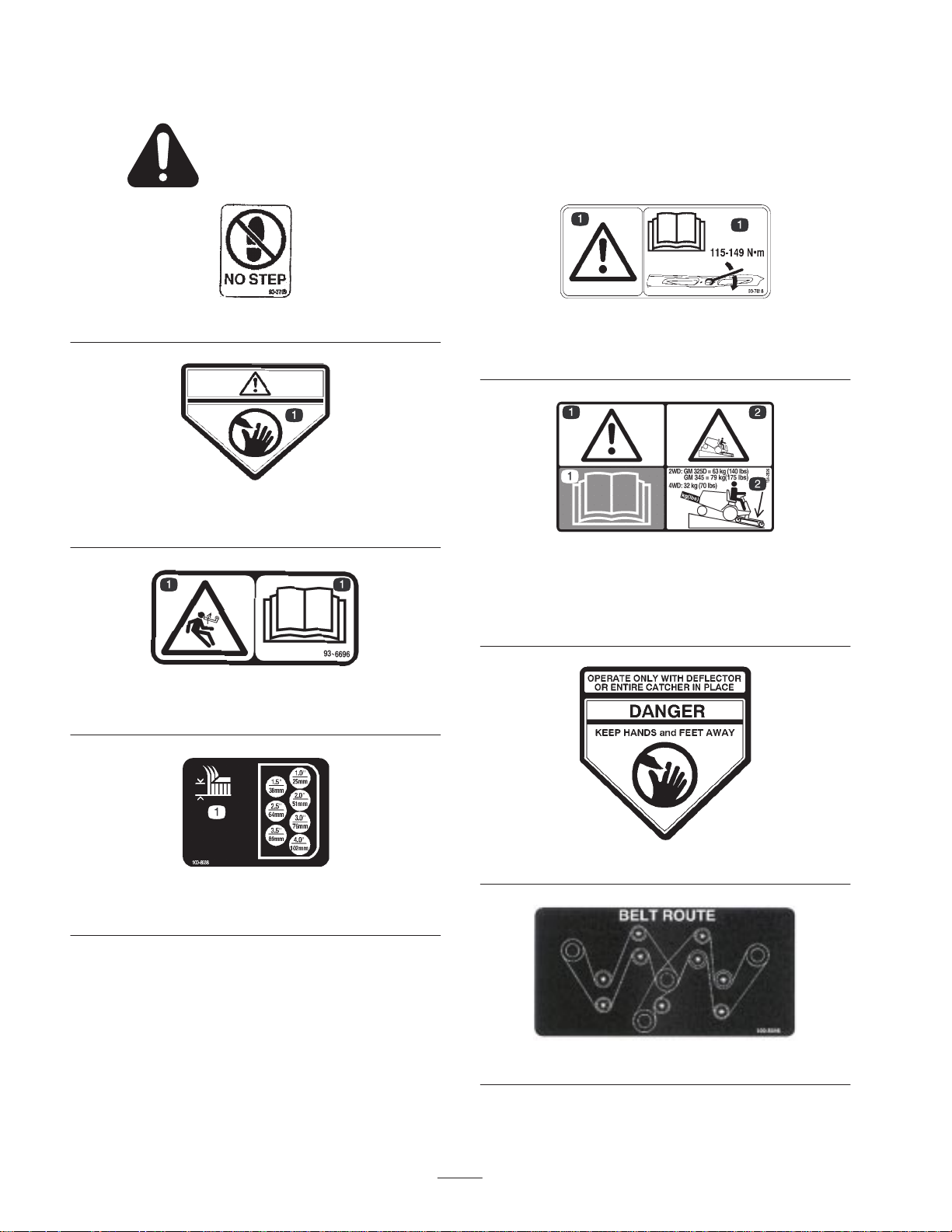
1. Using dimensions shown in figure 1, locate, mark and
drill (2) .28 in. dia. holes in traction unit platform. Use
caution when drilling as there are hoses and cables
under platform.
4.41”
1
Figure 3
1. Grass deflector
Mount Rear Castor Wheels
.75”
12.75”
Figure 1
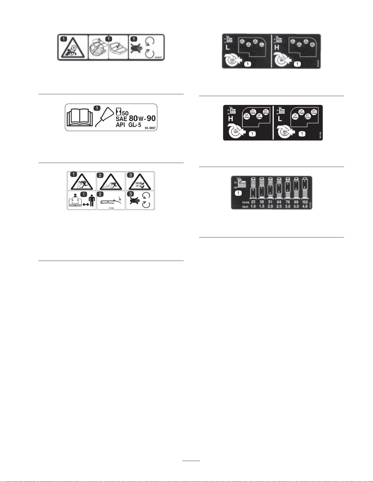
2. Secure hoses to under side of platform with clamp, (2)
brackets, capscrews and nuts. Position brackets to fit
contour of hoses and platform.
2
1
Figure 2
1. Clamp 2. Bracket
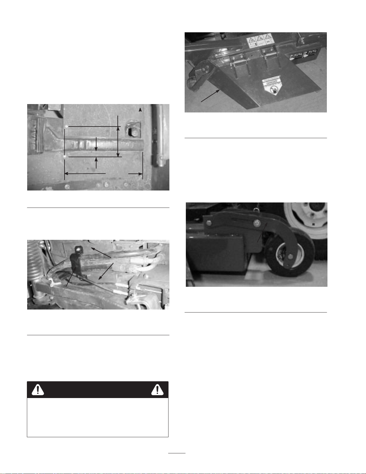
The rear castor wheels are shipped secured upside down to
deck brackets.
1. Remove capscrew and locknut securing front of rear
castor pivot to deck bracket.
1
Figure 4
1. Rear castor pivot arm
2. Turn pivot right side up and secure front of castor pivot
arm to front of deck bracket with capscrew and locknut
removed.
Grass Deflector
1. Remove shipping bands allowing deflector to be
lowered.
Warning
Deflector is spring loaded in the down
position and will rotate downward, if not
retrained, when band is cut. If done
improperly, personal injury may occur.
3. Align the pivot arm holes with selected height-of-cut
bracket holes in the deck frame, install clevis pin and
secure with hairpin cotter.
4. Repeat procedure on other castor wheel assembly.
Connect Right-hand Push Arm
To Cutting Unit
Note: Ball joints are shipped with traction unit.
1. Thread a jam nut fully onto ball joint.
8
Page 9

2. Thread ball joint into push arm adapter until a
dimension of 2-3/8 in. from end of adapter to center of
ball joint is attained. Do not tighten jam nut.
2
3
Figure 5
1. Ball joint
2. Jam nut
2-3/8
in.
3. Push arm adapter
Warning
Since the right hand push arm is spring
loaded to about 100 pounds, a helper is
1
needed to push the arm down. Sudden
release of the push arm could cause injury.
8. Have a helper carefully push down on the right push
arm until holes in ball joint mount line up with holes in
castor arm. Immediately slide a 4 x 4 in. block of wood
between top of push arm and underside of chassis.
9. Secure ball joint mount to castor arm with 2 flange head
capscrews and flange nuts previously removed.
Note: Capscrew heads to be positioned on inside of castor
arm.
3. Remove 2 flange head capscrews and flange nuts
securing right hand ball joint mount to castor arm.
Remove ball joint mount from castor arm.
4. Install ball joint to right hand ball joint mount with a
castle nut and cotter pin (Fig. 6).
5. Loosely mount push arm adapter to bottom of right
push arm with a push arm bracket and (4) capscrews,
flat washers, and flange head locknuts. Push arm
bracket to be positioned over and against end of right
push arm (Fig. 6).
Note: Push arm bracket must contact end of push arm.
6. Tighten fasteners securing right push arm adapter to
right push arm.
7. Move cutting unit into position in front of traction unit.
10.Tighten large jam nut securing ball joint to push arm
adapter (FIg. 5). When tightening jam nut, hold ball
joint straight to permit proper oscillation during raising
and lowering of cutting unit. Carefully remove wood
block holding push arm down.
Connect Left-hand Push Arm
To Cutting Unit
Warning
Since the left hand push arm is spring loaded
to about 100 pounds, a helper is needed to
push the arm down. Sudden release of the
push arm could cause injury.
1. Thread a jam nut fully onto ball joint.
2. Thread ball joint into left push arm until a dimension of
2-3/8 in. from end of push arm to center of ball joint is
attained. Do not tighten jam nut.
1
3
1. Right hand push arm
2. Push arm adapter
Figure 6
2
3. Push arm bracket
4. Ball joint mount
4
1. Ball joint
2. Jam nut
2
3
2-3/8 in.
1
Figure 7
3. Left push arm
9
Page 10

3. Remove 2 flange head capscrews and flange nuts
securing left-hand ball joint mount to castor arm.
Remove ball joint mount from castor arm.
4. Install ball joint to left-hand ball joint mount with a
castle nut and cotter pin.
1
2
3
Mount Front Lift Arm
1. Remove rubber bumper from bottom of traction T-bar.
1
2
Figure 9
1. Traction T–bar 2. Rubber bumper
Figure 8
1. L.H. Push arm
2. Ball joint
5. Have a helper carefully push down on the push arm
until holes in ball joint mount line up with holes in
castor arm. Immediately slide a 4 x 4 in. block of wood
between top of push arm and underside of chassis.
3. Ball joint mount
Warning
Make sure the wooden block does not slip
out accidentally. Sudden release of the push
arm could cause injury.
6. Secure ball joint mount to castor arm with flange head
capscrews and flange nuts previously removed.
Note: Flange head capscrew heads to be positioned on
inside of castor arm.
7. Tighten large jam nut securing ball joint to push arm.
When tightening jam nut, hold ball joint straight to
permit proper oscillation during raising and lowering of
cutting unit. Carefully remove wood block holding push
arm down.
Note: Periodically check and tighten the push arm adapter
capscrews.
2. Slide front lift arm onto traction unit t-bar, positioning
as shown in Figure 10.
3. Secure front lift arm to t-bar with with 2 capscrews and
locknuts.
2
1
Figure 10
1. Front lift arm 2. Traction unit T–bar
Mount Rear Lift Bracket
1. Loosely mount rear lift bracket to right push arm with
square U-bolt, 2 nuts, and flange nuts. Bracket to be
positioned on push arm so it is centered and parallel to
castor arm.
10
Page 11

1
1
3
Figure 11
1. Lift bracket
2. Square U–bolt
1
Figure 12
1. Lift bracket 2. Castor arm
3. U–bolt
2
Figure 13
1. Drive shaft
Install Lift Chains
1. Connect lift chains to lift arm and cutting unit chain
2
brackets with (6) shackles, (3/8 x 1-1/2 in.) shackle pins
and (1/8 x 3/4 in.) cotter pins. To ensure that cutting
unit lifts properly, secure chains to the following links
when connecting:
• Front Left – 8th link
• Front Right – 8th link
• Rear – 14th link (All links)
2. Check operation to ensure that all chains lift deck tight
against stops when lift arm is raised.
2. Hook H.O.C. chain onto remaining U-bolt.
3. Thread a hex nut onto each end of U-bolt.
4. Loosely mount U-bolt and H.O.C. chain to rear lift
bracket 2 nuts and 2 flange nuts
5. Mount height-of-cut chain to 2 in. height-of-cut hole
with clevis pin and hairpin cotter.
6. Position rear castors in 2 in. height-of-cut.
7. Adjust nuts on U-bolt until rear of deck is parallel to
floor (Distance from floor to bottom rear edge of all
three deck chambers must be equal).
Install Drive Shaft To Traction
Unit
Note: To ease installation of PTO shaft, remove right
traction tire.
1. Slide smaller yoke end of drive shaft onto traction unit
PTO shaft while aligning mounting holes. Secure with
roll pin.
3
1. Front left lift chain
2. Front right lift chain
1
2
Figure 14
3. Rear lift chain
11
Page 12

Adjust Counter Balance Spring
1. Tighten nuts on adjusting rod until there is equal weight
on castor wheels of left and left center chambers.
1
2
Figure 15
1. Counterbalance spring 2. Adjusting rod
Grease Cutting Unit
Before the cutting unit is operated, it must be greased to
ensure proper lubricating characteristics: refer to
Lubrication, page 13. Failure to properly grease the cutting
unit will result in premature failure of critical parts.
Install Rear Weight
GROUNDSMASTER 300 Series Traction Units comply
with ANSI B71.4–1999 Standard when equipped with rear
weight. Refer to chart in Traction Unit Operator’s Manual
to determine combinations of weight required. Order parts
from your local Authorized Toro Distributor.
12
Page 13

Before Operating
Check Lubricant In Gear Box
The gear box in designed to operate on SAE 80–90 wt. gear
lube. Although the gear box is shipped with lubricant from
the factory, check the level before operating the cutting
unit.
1. Position the machine and cutting unit on a level surface.
2. Remove check plug from side of gear box and make
sure lubricant is up to bottom of hole. If level of
lubricant is low, add enough lubricant to bring it up to
bottom of hole.
Front Castor Wheels
Figure 17
1. Remove H.O.C. cap from spindle shaft and slide spindle
out of front castor arm. Slide spacers onto spindle shaft
to get desired height-of-cut.
3
3
1
2
Figure 16
1. Fill/check plug 2. Drain plug
Adjusting Height-of-cut
The height-of-cut is adjustable from 1 to 4 inches in 1/4
inch increments.
1. Start the engine and raise the cutting unit so
height-of-cut can be changed. Stop engine after cutting
unit is raised.
4
4
1
Figure 18
1. Front castor wheel
2. H.O.C. cap
2. Push castor spindle through front castor arm install
remaining spacers onto spindle and install HOC cap to
secure assembly.
3. Spacer
4. Washer
13
Page 14

Rear Castor Wheels
Figure 19
1. Remove hairpin cotter and cotter pin securing rear
castor pivot arm to deck bracket.
1
1
Figure 21
1. H.O.C chain
Figure 20
1. Rear castor pivot
2. Align the pivot arm holes with selected height-of-cut
bracket holes in the deck frame, install cotter pin and
secure with hairpin cotter.
Rear Deck Chain
1. Remove hair pin cotter and clevis pin securing
height-of-cut chain to chamber bracket.
2. Mount height-of-cut chain to desired height-of-cut hole
with clevis pin and hair pin cotter.
Figure 22
Check Tire Pressure
Ensure that the air pressure in the front and rear castor
wheels is 40 psi (276 kPa).
Important Maintain even pressure in all tires to ensure
a good quality-of-cut and proper machine performance. Do
not under-inflate.
14
Page 15

Adjust Skid
Skid, on right side of cutting unit, should be located in
upper holes for 1 and 1-1/2 inch heights-of-cut and lower
holes for 2 to 4 inch heights-of-cut.
1. Adjust skid by removing flange nuts, positioning as
desired and re-installing flange nuts.
1
Figure 23
1. Skid
1
Figure 24
1. Roller
Adjust Rollers
The front anti-scalp rollers and the rear anti-scalp rollers,
located on the center deck, should be located in upper holes
for 1 and 1-1/2 inch heights-of-cut and lower holes for 2 to
5 inch heights-of-cut. Six rollers are located on the deck,
two under the main deck and two on each wing.
1. Adjust anti-scalp rollers by removing screw securing
roller shaft to deck, positioning roller as desired, and
reinstalling shaft with screw, washers, and nut (Fig. 24).
2. The two outside wing deck rollers can be adjusted at the
roller, or the bracket can be repositioned on the deck.
15
Page 16

Operation
Grass Deflector
Warning
The grass deflector (Fig. NO TAG) is a safety
device that diverts grass and other foreign
objects being discharged downward. WE
STRONGLY RECOMMEND THAT THE
DEFLECTOR BE IN ITS NORMAL OPERATING
POSITION WHENEVER THE CUTTING UNIT IS
ENGAGED. NEVER OPERATE CUTTING UNIT
WITH THE DEFLECTOR REMOVED FROM
THE CUTTING UNIT OR IT TIED/BLOCKED IN
A RAISED POSITION. SINCE THE BLADES
COULD THEN THROW DEBRIS A
CONSIDERABLE DISTANCE WITH
SUFFICIENT FORCE TO CAUSE PERSONAL
INJURY OR DAMAGE TO PROPERTY. If the
grass deflector is damaged, repair or replace
the affected part(s).
Note: The deflector is spring loaded into its
downward normal operating position, but the
operator can temporarily swing it out of the
way to facilitate loading in a trailer or when
otherwise necessary.
• SELECT THE PROPER HEIGHT–OF–CUT
SETTING TO SUIT CONDITIONS – Remove
approximately one inch or no more than 1/3 of the grass
blade when cutting. In exceptionally lush and dense
grass you may have to raise your height–of–cut setting
another notch. When cutting in 1 in. or 1-1/2 in.
height-of-cut, add a second washer between rear castor
forks and bottom of castor arm housings to increase
blade rake.
• MOWING IN EXTREME CONDITIONS – Air is
required to cut and recut grass clippings in mower
housing, so do not set height-of-cut too low or totally
surround housing by uncut grass. Always try to have
one side of the mower housing free from uncut grass,
allowing air to be drawn into housing. When making an
initial cut thru center of uncut area, operate machine
slower and back up if mower starts to clog.
• ALWAYS START MOWING WITH SHARP BLADES
– A sharp blade cuts cleanly and without tearing or
shredding the grass blades like a dull blade. Tearing and
shredding causes the grass to turn brown at the edges
which impairs growth and increases susceptibility to
diseases. Make sure blade is in good condition and a
full sail is present.
• CHECK CONDITION OF DECK – Make sure cutting
chambers are in good condition. Straighten any bends in
chamber components to ensure correct blade
tip/chamber clearance.
• STOPPING – If forward motion has to be stopped while
cutting, a clump of grass clippings may be deposited on
lawn. Follow this procedure for stopping while cutting:
2
1
Figure 25
1. Grass deflector 2. Springs
Operating Tips
• MOW WHEN GRASS IS DRY–Mow either in the late
morning to avoid the dew, which causes grass clumping
or in late afternoon to avoid the damage that can be
caused by direct sunlight on the sensitive, freshly
mowed grass.
• With deck engaged, move onto a previously cut
area.
• Shift to neutral, move throttle control lever to
SLOW position and rotate ignition key to OFF.
• AFTER OPERATING – To ensure optimum
performance, clean underside of mower housing,
especially around inserts (kickers) after each use. If
residue is allowed to build up in mower housing and on
inserts, cutting performance will decrease.
16
Page 17

Maintenance
Greasing The Cutting Unit
The cutting unit must be lubricated regularly. If machine is
operated under normal conditions, lubricate castor bearings
and bushings with No. 2 general purpose lithium base
grease or molybdenum base grease, after every 8 hours of
operation or daily, whichever comes first.
1. The cutting unit has bearings and bushings that must be
lubricated, and these lubrication points are: front castor
spindle bushings (2) (Fig. 26); front castor wheel
bearings (4) (Fig. 26); rear castor wheel bearings (2)
(Fig. 28); blade spindle bearings (3) (Fig. 28); right and
left push arm ball joints (Fig. 28); drive shaft (3)
(Fig. 28) idler arm pivots (3) (Fig. 29); and deck pivot
pins (4) (Fig. 30)
Figure 28
Figure 29
Figure 30
Figure 26
Figure 27
2. Position the machine on a level surface and lower
cutting unit. Remove fill/check plug from side of gear
box (Fig. 31) and make sure lubricant is up to bottom of
hole. If level of lubricant is low, add SAE 80–90 wt.
gear lube until level is up to bottom of hole.
1
2
Figure 31
1. Fill/check plug 2. Drain plug
17
Page 18

Trouble Shooting
85 T o 110
18
Page 19

Separating Cutting Unit From
Mounting Cutting Unit To
Traction Unit
1. Position machine on level surface, lower cutting unit to
floor, shut engine off and engage parking brake.
2. Remove self tapping screws securing shield to top of
cutting unit and set shield aside.
3. Drive out roll pin securing drive shaft yoke to input
shaft of gear box. Loosen capscrews and locknuts and
slide yoke off input shaft. If traction unit will be used
without the cutting unit, drive roll pin out of yoke at
traction unit PTO shaft and remove entire drive shaft
from traction unit.
Danger
Do not start the engine and engage the PTO
lever when PTO shaft is not connected to
gear box on cutting unit. If engine is started
and PTO shaft is allowed to rotate, serious
injury could result.
4. Disconnect cotter pins and clevis pins securing lift
chains to lift arms.
Traction Unit
1. Position machine on a level surface and shut engine off.
2. Move cutting unit into position in front of traction unit.
Warning
Since the left hand push arm is spring loaded
to about 100 pounds, a helper is needed to
push the arm down. Sudden release of the
push arm could cause injury.
3. Have a helper carefully push down on the right push
arm until holes in ball joint mount line up with holes in
castor arm.
4. Secure ball joint mount to castor arm with flange head
capscrews and flange nuts. Capscrew heads to be
positioned to inside of castor arm.
5. Have a helper carefully push down on the left push arm
until holes in ball joint mount line up with holes in
castor arm. Immediately slide a 4 x 4 in. block of wood
between top of push arm and underside of chassis
Warning
Since the right hand push arm is spring
loaded to about 100 pounds, a helper is
needed to push the arm down. Sudden
release of the push arm could cause injury.
5. Have a helper push down on the right push arm while
you remove the flange head capscrews and locknuts
securing the ball joint mount to castor arm on cutting
unit. Now the helper can carefully allow push arm to
move upward, which will gradually release the 100
pounds of spring load.
6. Have a helper push down on the left push arm while
you remove the flange head capscrews and locknuts
securing the ball joint mount to castor arm on cutting
unit. Now the helper can carefully allow push arm to
move upward, which will gradually release the 150
pounds of spring load.
7. Roll the cutting unit away from the traction unit.
Warning
Make sure the wooden block does not slip
out accidentally. Sudden release of the push
arm could cause injury.
6. Secure ball joint mount to castor arm with flange head
capscrews and flange nuts. capscrew heads to be
positioned to inside of castor arm. Chain bracket to be
mounted in forward set of holes.
7. Carefully remove wood block holding push arm down.
8. Line up holes in yoke and input shaft of gear box. Slide
yoke onto shaft and secure together with a roll pin and 2
capscrews (5/16 x 1-3/4 in.) and locknuts (5/16 in.).
Adjusting Drive Belts
The blade drive belts are tensioned by the spring loaded
idlers, are very durable. However, after many hours of use,
the belts will stretch and will need adjusting.
1. Lower cutting unit to the shop floor. Remove belt
covers from top of cutting unit and set covers aside.
2. Adjust spring tensioning rods until 10 lb. tension is
achieved for side belts and 30 lb. tension for center gear
box belt.
19
Page 20

MAINTENANCE
1
Figure 32
1. Spring tensioning rod (3)
Replacing Drive Belts
The blade drive belts, tensioned by the spring loaded idlers,
are very durable. However, after many hours of use, the
belts will show signs of wear. Signs of a worn belt are:
squealing when belt is rotating, blades slipping when
cutting grass, frayed edges, burn marks, and cracks.
Replace the belt if any of these conditions are evident.
Servicing Front Bushings In
Castor Arms
The castor arms have bushings pressed into the top and
bottom of the tube and after many hours of operation, the
bushings will wear. To check the bushings, move castor
fork back and forth and from side to side. If castor spindle
is loose inside the bushings, bushings are worn and must be
replaced.
1. Raise cutting unit so wheels are off floor and block it so
it cannot fall accidentally.
2. Remove tensioning cap, spacer(s) and thrust washer
from top of castor spindle.
3. Pull castor spindle out of mounting tube. Allow thrust
washer and spacer(s) to remain on bottom of spindle.
4. Insert pin punch into top or bottom of mounting tube
and drive bushing out of tube. Also drive other bushing
out of tube. Clean inside of tubes to remove dirt.
1. Lower cutting unit to the shop floor. Remove belt
covers from top of cutting unit and set covers aside.
2. To replace gear box belt, loosen spring tension rod and
remove belt. Retention new belt to 30 lb. Refer to
Figure 33 for belt routing.
Figure 33
3. To replace wing belts, loosen spring tension rod and
remove gear box belt.
4. Pull spring loaded idler pulley away from belt, with
hand, to relieve belt tension and remove belt. Retention
new belts to 10 lb. Refer to Figure 33 for belt routing.
5. Install belt covers.
2
1
Figure 34
1. Front castor arm tube 2. Bushings
5. Apply grease to inside and outside of new bushings.
Using a hammer and flat plate, drive bushings into
mounting tube.
6. Inspect castor spindle for wear and replace it if
damaged.
7. Push castor spindle through bushings and mounting
tube. Slide thrust washer and spacer(s) onto spindle.
Install tensioning cap on castor spindle to retain all parts
in place.
20
Page 21

Servicing Castor Wheels And
Replacing Grass Deflector
Bearings
The castor wheel rotates on a high-quality roller bearing
and is supported by a spanner bushing. Even after many
hours of use, provided that the bearing was kept
well-lubricated, bearing wear will be minimal. However,
failure to keep bearing lubricated will cause rapid wear. A
wobbly castor wheel usually indicates a worn bearing.
1. Remove locknut from capscrew holding castor wheel
assembly between castor fork. Grasp castor wheel and
slide capscrew out of fork.
2. Pull spanner bushing out of wheel hub.
2
2
6
1
5
4
3
6
1. Position machine on a level surface, raise cutting unit,
engage parking brake, be sure traction pedal is in
neutral position, PTO lever in OFF position, shut engine
OFF, and remove key from switch. Block cutting unit to
prevent it from falling accidentally.
2. Remove two capscrews, locknuts, and springs securing
deflector mounts to pivot brackets.
3. To remove the pivot brackets, remove carriage bolts and
nuts.
4. Reinstall pivot brackets on top of discharge opening
with carriage bolts and nuts. Head of carriage bolts
must be on inside of cutting unit.
5. Position deflector mounts on pivot brackets and secure
parts together with capscrews, locknuts and springs.
Both locknuts must face each other. Tighten locknuts
until they are flush against deflector pivots.
Figure 35
1. Castor wheel
2. Capscrew & locknut
3. Bushing (2)
3. Remove bushing from wheel hub and allow bearing to
fall out. Remove bushing from opposite side of wheel
hub.
4. Check the bearing, spanner and inside of wheel hub for
wear. Replace defective parts.
5. To assemble the castor wheel, push bushing into wheel
hub. Slide bearing into wheel hub. Push other bushing
into open end of wheel hub to captivate the bearing
inside the wheel hub.
6. Carefully slide spanner through the bushings and the
wheel hub.
7. Install castor wheel assembly between castor fork and
secure in place with capscrew, washers and locknut.
8. Lubricate castor wheel bearing through grease fitting,
using No. 2 general purpose lithium base grease.
4. Spanner bushing
5. Roller bearing
6. Washer
2
1
Figure 36
1. Grass deflector 2. Pivot springs
6. Lift deflector and allow it to drop to check spring
tension. Deflector must be held firmly in full downward
position by spring tension. Correct if necessary.
Removing Cutter Blade
The blade must be replaced if a solid object is hit, the blade
is out-of-balance or if the blade is bent. Always use genuine
Toro replacement blades to be sure of safety and optimum
performance. Never use replacement blades made by other
manufacturers because they could be dangerous.
1. Raise cutting unit to highest position, shut the engine
off and engage the parking brake. Block cutting unit to
prevent it from falling accidentally.
2. Grasp end of blade using a rag or thickly padded glove.
Remove blade bolt, lock washer, anti-scalp cup, and
blade from spindle shaft.
21
Page 22

1. Blade bolt
2. Lockwasher
Figure 37
3. Anti–scalp cup
3
2
1
Figure 38
3. Install blade—sail facing toward cutting unit with
anti-scalp cup, lock washer, and blade bolt. Tighten
blade bolt to 85–110 ft.-lb.
Warning
Do not try to straighten a blade that is bent,
and never weld a broken or cracked blade.
Always use a new blade to ensure continued
safety certification of the product.
Inspecting And Sharpening
Blade
1. Raise cutting unit to highest position, shut the engine
off and engage the parking brake. Block cutting unit to
prevent it from falling accidentally.
2. Examine cutting ends of the blade carefully, especially
where the flat and curved parts of the blade meet
(Fig. 38-A). Since sand and abrasive material can wear
away the metal that connects the flat and curved parts of
the blade, check the blade before using the machine. If
wear is noticed (Fig. 38-B), replace the blade: refer to
Removing Cutter Blade.
3. Inspect cutting edges of all blades. Sharpen the cutting
edges if they are dull or nicked. Sharpen only the top of
the cutting edge and maintain the original cutting angle
to make sure of sharpness (Fig. 39). The blade will
remain balanced if same amount of metal is removed
from both cutting edges.
SHARPEN AT THIS
ANGLE ONLY
END VIEW
Figure 39
4. To check blade for being straight and parallel, lay blade
on a level surface and check its ends. Ends of blade
must be slightly lower than the center, and cutting edge
must be lower than the heel of the blade. This blade will
produce good quality of cut and require minimal power
from the engine. By contrast a blade that is higher at the
ends than the center, or if cutting edge is higher than the
heel, the blade is bent or warped and must be replaced.
5. Install blade—sail facing toward cutting unit with
anti-scalp cup, lock washer, and blade bolt. Tighten
blade bolt to 85–110 ft.-lb.
Danger
If blade is allowed to wear, a slot will form
between the sail and flat part of the blade
(Fig. 38-C). Eventually a piece of the blade
may break off and be thrown from under the
housing, possibly resulting in serious injury
to yourself or bystander.
22
Page 23

Correcting Cutting Unit
Mismatch
If there is mismatch between the blades, the grass will
appear streaked when it is cut. This problem can be
corrected by making sure the blades are straight and all
blades are cutting on the same plane.
1. Using a 3 foot long carpenters level, find a level surface
on the shop floor.
2. Raise height-of-cut to the highest position: refer to
Adjusting Height-of-Cut.
3. Lower cutting unit onto flat surface. Remove covers
from top of cutting unit.
4. Unhook spring from idler arm bracket to release belt
tension.
5. Rotate blades until the ends face forward and backward.
Measure from floor to front tip of cutting edge and
remember this dimension. Then rotate same blade so
opposite end is forward and measure again. The
difference between dimensions must not exceed 1/8 of
an inch. If dimension exceeds 1/8 of an inch, replace the
blade because it is bent. Make sure to measure all
blades.
6. Compare measurements of outer blades with the center
blade. Center blade must not be more than 3/8 of an
inch lower than the outer blades. If center blade is more
than 3/8 of an inch lower than the outer blades. proceed
to step 7 and add shims between spindle housing and
bottom of cutting unit.
7. Remove capscrews, flatwashers, lockwashers and nuts
from outer spindle in the area where shims must be
added. To raise or lower the blade, add a shim, Part No.
3256-24, between spindle housing and bottom of
cutting unit. Continue to check alignment of blades and
add shims until tips of blades are within the required
dimension.
Important Do not use more than three shims at any
one hole location. Use decreasing numbers of shims in
adjacent holes if more than one shim is added to any
one hole location.
8. Hook spring onto idler arm bracket. Reinstall belt
covers.
23
Page 24

The Toro General Commercial Products Warranty
A Two-Year Limited Warranty
Conditions and Products Covered
The Toro Company and its affiliate, Toro Warranty Company,
pursuant to an a g r eement between them, jointly warrant your 1996
or newer Toro Commercial Product (“Product”) purchased after
January 1, 1997, to be free from defects in materials or
workmanship for tw o years or 1500 operational hours*, whichever
occurs first. Where a warrantable condition exists, we will repair the
Product at no cost to you including diagnosis, labor, parts, and
transportation. This warranty begins on the date the Product is
delivered to the original retail purchaser.
* Product equipped with hour meter
Instructions for Obtaining Warranty Service
You are responsible for notifying the Commercial Products
Distributor or Authorized Commercial Products Dealer from whom
you purchased the Product as soon as you believe a warrantable
condition exists.
If you need help locating a Commercial Products Distributor or
Authorized Dealer, or if you have questions regarding your
warranty rights or responsibilities, you may contact us at:
Toro Commercial Products Service Department
Toro Warranty Company
8111 Lyndale Avenue South
Bloomington, MN 55420-1196
952-888-8801 or 800-982-2740
E-mail: commercial.service@toro.com
Owner Responsibilities
As the Product owner, you are responsible for required maintenance and adjustments stated in your operator’s manual. Failure
to perform required maintenance and adjustments can be grounds
for disallowing a warranty claim.
Items and Conditions Not Covered
Not all product failures or malfunctions that occur during the
warranty period are defects in materials or workmanship. This
express warranty does not cover the following:
• Product failures which result from the use of non-Toro
replacement parts, or from installation and use of add-on,
modified, or unapproved accessories
• Product failures which result from failure to perform required
maintenance and/or adjustments
• Product failures which result from operating the Product in an
abusive, negligent or reckless manner
• Parts subject to consumption through use unless found to be
defective. Examples of parts which are consumed, or used up,
during normal Product operation include, but are not limited to,
blades, reels, bedknives, tines, spark plugs, castor wheels,
tires, filters, belts, etc.
• Failures caused by outside influence. Items considered to be
outside influence include, but are not limited to, weather,
storage practices, contamination, use of unapproved coolants,
lubricants, additives, or chemicals, etc.
• Normal “wear and tear” items. Normal “wear and tear” includes,
but is not limited to, damage to seats due to wear or abrasion,
worn painted surfaces, scratched decals or windows, etc.
Parts
Parts scheduled for replacement as required maintenance are
warranted for the period of time up to the scheduled replacement
time for that part.
Parts replaced under this warranty become the property of Toro.
T oro will make the final decision whether to repair any existing part
or assembly or replace it. Toro may use factory remanufactured
parts rather than new parts for some warranty repairs.
General Conditions
Repair by an Authorized Toro Distributor or Dealer is your sole
remedy under this warranty.
Neither The Toro Company nor Toro Warranty Company is
liable for indirect, incidental or consequential damages in
connection with t h e use of the Toro Products covered by this
warranty, including any cost or expense of providing substitute equipment or service during reasonable periods of
malfunction or non-use pending completion of repairs under
this warranty. Except for the Emissions warranty referenced
below, if applicable, there is no other express warranty. All
implied warranties of merchantability and fitness for use are
limited to the duration of this express warranty.
Some states do not allow exclusions of incidental or consequential
damages, or limitations on how long an implied warranty lasts, so
the above exclusions and limitations may not apply to you.
This warranty gives you specific legal rights, and you may also
have other rights which vary from state to state.
Note regarding engine warranty: The Emissions Control System
on your Product may be covered by a separate warranty meeting
requirements established by the U.S. Environmental Protection
Agency (EPA) and/or the California Air Resources Board (CARB).
The hour limitations set forth above do not apply to the Emissions
Control System Warranty. Refer to the Engine Emission Control
Warranty Statement printed in your operator’s manual or contained in the engine manufacturer’s documentation for details.
Countries Other than the United States or Canada
Customers who have purchased Toro products exported from the United States or Canada should contact their Toro Distributor (Dealer)
to obtain guarantee policies for your country, province, or state. If for any reason you are dissatisfied with your Distributor’s service or
have difficulty obtaining guarantee information, contact the Toro importer. If all other remedies fail, you may contact us at Toro Warranty
Company.
Part No. 374-0031 Rev. –
 Loading...