

Page 1
Form No. 3356–519 Rev A
Rotary Hydraulic Broom
Groundsmaster) 300 Series Traction Units
Model No. 30743—Serial No. 260000001 and Up
Operator’s Manual
English (EN)
Page 2

Contents
Introduction
Introduction 2. . . . . . . . . . . . . . . . . . . . . . . . . . . . . . . .
Safety 3. . . . . . . . . . . . . . . . . . . . . . . . . . . . . . . . . . . . .
Before Operating 3. . . . . . . . . . . . . . . . . . . . . . . . .
While Operating 3. . . . . . . . . . . . . . . . . . . . . . . . . .
Maintenance 4. . . . . . . . . . . . . . . . . . . . . . . . . . . . .
Safety and Instruction Decals 4. . . . . . . . . . . . . . . .
Specifications 6. . . . . . . . . . . . . . . . . . . . . . . . . . . . . . .
General Specifications 6. . . . . . . . . . . . . . . . . . . . .
Optional Equipment 6. . . . . . . . . . . . . . . . . . . . . . .
Setup 7. . . . . . . . . . . . . . . . . . . . . . . . . . . . . . . . . . . . .
General 7. . . . . . . . . . . . . . . . . . . . . . . . . . . . . . . . .
Head and Tank Assembly 7. . . . . . . . . . . . . . . . . . .
Electric Swivel Option
(Model No. 30728) 7. . . . . . . . . . . . . . . . . . . . . .
Broom Control Box and Wiring
(Electric Swivel Option) 7. . . . . . . . . . . . . . . . . .
Install the Push Arm 7. . . . . . . . . . . . . . . . . . . . . . .
Pump Mounting 8. . . . . . . . . . . . . . . . . . . . . . . . . .
Install Rear Weight 9. . . . . . . . . . . . . . . . . . . . . . . .
Before Operating 10. . . . . . . . . . . . . . . . . . . . . . . . . . . .
Adjust Brush Down Pressure 10. . . . . . . . . . . . . . . .
Broom Lift Chain Tension 10. . . . . . . . . . . . . . . . . .
Check Hydraulic System 10. . . . . . . . . . . . . . . . . . .
Operating Instructions 11. . . . . . . . . . . . . . . . . . . . . . . .
Operation 11. . . . . . . . . . . . . . . . . . . . . . . . . . . . . . .
Broom Angle 11. . . . . . . . . . . . . . . . . . . . . . . . . . . .
Operating Tips 11. . . . . . . . . . . . . . . . . . . . . . . . . . .
Ground Speed 11. . . . . . . . . . . . . . . . . . . . . . . . . . . .
Curb Climbing and Trailer Loading 11. . . . . . . . . . .
Maintenance 12. . . . . . . . . . . . . . . . . . . . . . . . . . . . . . . .
Lubrication 12. . . . . . . . . . . . . . . . . . . . . . . . . . . . . .
Disconnecting the Broom from the Traction Unit 12
Changing Brush Elements 12. . . . . . . . . . . . . . . . . .
Broom Lift Chain Tension 13. . . . . . . . . . . . . . . . . .
Changing Hydraulic System Oil And Filter 13. . . . .
Servicing Castor Fork Bushings 13. . . . . . . . . . . . . .
Servicing Castor Wheel And Bearing 14. . . . . . . . .
The Toro General Commercial Products Warranty 16. .
Page
Read this manual carefully to learn how to operate and
maintain your product properly. The information in this
manual can help you and others avoid injury and product
damage. Although Toro designs and produces safe
products, you are responsible for operating the product
properly and safely.
Whenever you need service, genuine Toro parts, or
additional information, contact an Authorized Service
Dealer or Toro Customer Service and have the model and
serial numbers of your product ready. The two numbers are
stamped on a plate which is located on the broom.
Write the product model and serial numbers in the space
below:
Model No.
Serial No.
This manual identifies potential hazards and has special
safety messages that help you and others avoid personal
injury and even death. Danger, Warning, and Caution are
signal words used to identify the level of hazard. However,
regardless of the hazard, be extremely careful.
Danger signals an extreme hazard that will cause serious
injury or death if you do not follow the recommended
precautions.
Warning signals a hazard that may cause serious injury or
death if you do not follow the recommended precautions.
Caution signals a hazard that may cause minor or moderate
injury if you do not follow the recommended precautions.
This manual uses two other words to highlight information.
Important calls attention to special mechanical
information and Note: emphasizes general information
worthy of special attention.
W 2006 by The Toro Company
8111 Lyndale Avenue South
Bloomington, MN 55420-1196
All Rights Reserved
Printed in the USA
2
Page 3

Safety
Hazard control and accident prevention are dependent
upon the awareness, concern, and proper training of the
personnel involved in the operation, transport,
maintenance, and storage of the machine. Improper use
or maintenance of the machine can result in injury or
death. To reduce the potential for injury or death,
comply with the following safety instructions.
– Ensure the appropriate rear weight kits are added to
rear of traction unit when the broom is installed.
Refer to Install Rear Weight on page 9.
– When transporting, especially travelling on a slope,
rotate the broom up but keep castor wheels on the
ground, travel slowly and do not brake suddenly.
– Do not drive on highway or public roads.
– Always SLOW the traction unit when approaching
and while making a turn.
Before Operating
• Read and understand the contents of this Operator’s
Manual before operating the machine. Become familiar
with all of the controls and know how to stop quickly. A
free replacement manual is available by sending the
complete Model and Serial Number to The Toro
Company, 8111 Lyndale Avenue South, Bloomington,
Minnesota 55420-1196.
• Never allow children to operate the machine. Do not
allow adults to operate machine without proper
instruction. Only trained operators who have read this
manual should operate this machine.
• Never operate the machine when under the influence of
drugs or alcohol.
• Keep all bystanders away from the operating area.
• Keep all shields and safety devices in place. If a shield,
safety device, or decal is illegible or damaged, repair or
replace it before operation is commenced. Also tighten
any loose nuts, bolts, and screws to ensure that the
machine is in safe operating condition.
• Do not operate the machine while wearing sandals,
tennis shoes, sneakers, or shorts. Also, do not wear
loose fitting clothing which could get caught in moving
parts. Always wear long pants and substantial shoes.
Wearing safety glasses, safety shoes, and a helmet is
advisable and required by some local ordinances and
insurance regulations.
While Operating
• This Rotary Hydraulic Broom is only intended for use
with Groundsmaster 300 Series Traction Units.
• Hearing protection is recommended for prolonged
exposure to reduce the potential of permanent hearing
damage.
• Using the machine demands attention. This attachment
adds extra weight to the traction unit and when in the
raised position can effect the ability to steer the traction
unit, especially on slopes. Drive the vehicle safely and
adhere to the following points in order to prevent loss of
control:
– Always SLOW the traction unit when driving in
unfamiliar areas or over rough terrain.
– Always SLOW the traction unit when changing
direction of travel or preparing to stop.
– When turning or driving on slopes, always SLOW
the traction unit, then turn to prevent loss of control
and possible upset.
– DO NOT make sudden or sharp turns. DO NOT
suddenly change direction of travel on an incline,
ramp, grade, slope or similar surface.
– Always adjust the traction unit speed to allow for
existing ground conditions such as wet slick
surfaces, loose sand or gravel and/or low visibility
conditions such as dim or bright lighting, fog, mist
or rain.
– Be especially careful when driving down an incline
or slope. Drive the vehicle UP and DOWN the face
of the slopes, inclines or grades whenever possible.
DO NOT DRIVE across the face if at all possible.
There is a risk of upsetting the vehicle, which can
result in serious injury or death.
– Before backing up, look to the rear and assure no
one is behind the machine.
• Stay away from discharge area when machine is
operating. Keep all bystanders away from the discharge
area and do not direct discharge toward bystanders.
• DO NOT TAKE AN INJURY RISK! When a person,
pet or animal appears unexpectedly in or near the
operating area STOP OPERATION. Careless operation,
combined with terrain angles, ricochets, or improperly
positioned guards can lead to thrown object injuries.
• Lower the broom to the ground and remove key from
ignition whenever machine is left unattended.
• If engine stalls or machine loses headway and cannot
make it to the top of a slope, do not turn machine
around. Always back slowly straight down the slope.
• Watch out for traffic when near or crossing roads.
Always yield the right of way to pedestrians and other
vehicles.
3
Page 4

• If the Rotary Hydraulic Broom begins to vibrate
abnormally, stop immediately. Shut off the traction unit
engine. Repair all damage before commencing
operation.
• Be sure that the machine is in safe operating condition
by keeping nuts, bolts, and screws tight. Check all bolts
and nuts frequently to be sure that they are tightened to
specification.
• Before servicing or making any adjustments to the
Rotary Hydraulic Broom:
– Stop the traction unit and set the parking brake.
– Shut off the traction unit’s engine and remove key
from ignition.
• Keep all nuts, bolts and other fasteners tightened
securely. Replace any parts removed during servicing or
adjustments.
• To assure optimum performance and continued safety of
this product, always use genuine TORO replacement
parts. Replacement parts and accessories made by other
manufacturers may affect the product’s operation,
performance or durability. Such use could also void the
warranty of The Toro Company.
Maintenance
• Remove the key from the ignition switch to prevent
accidental starting of the engine when servicing,
adjusting, or storing the machine.
• Perform only those maintenance instructions described
in this manual. If major repairs are ever needed or
assistance is desired, contact an Authorized Toro
Distributor.
• Make sure all hydraulic line connectors are tight and all
hydraulic hoses and lines are in good condition before
applying pressure to the system.
• Keep your body and hands away from pin hole leaks or
nozzles that eject hydraulic fluid under high pressure.
Use paper or cardboard, not your hands, to search for
leaks. Hydraulic fluid escaping under pressure can have
sufficient force to penetrate the skin and cause serious
injury. Seek immediate medical attention if fluid is
injected into skin.
• Before disconnecting or performing any work on the
hydraulic system, all pressure in the system must be
relieved by stopping the engine and lowering the cutting
units and attachments to the ground.
• If the engine must be running to perform a maintenance
adjustment, keep hands, feet, clothing, and any parts of
the body away from the cutting units, attachments, and
any moving parts. Keep everyone away.
• To ensure optimum performance and safety, always
purchase genuine Toro replacement parts and
accessories to keep the machine all Toro. Never use
“will-fit” replacement parts and accessories made by
other manufacturers. Look for the Toro logo to ensure
genuineness. Using unapproved replacement parts and
accessories could void the warranty.
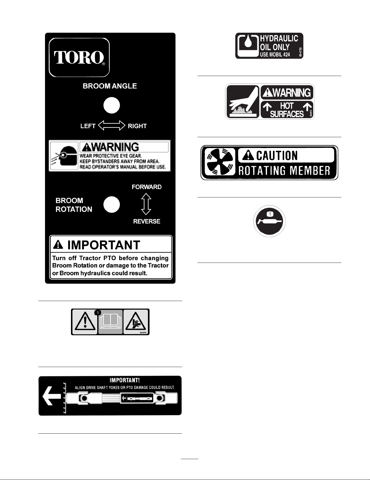
Safety and Instruction Decals
Safety decals and instructions are easily visible to the operator and are located near any area
of potential danger. Replace any decal that is damaged or lost.
99-6542
4
Page 5
85-4730
54-0910
99-6540
100-5854
94-8701
1. Warning—read the Operator’s Manual; crushing hazard of
hand.
58-6520
1. Grease
99-6522
5
Page 6

Specifications
General Specifications
Brush Filament Material Virgin polypropylene, high carbon wire or combination of both.
Brush Diameter 24 inches.
Sweeping Width Angle
Broom Swing/Control Manual pin position.
Broom Ground Pressure
Adjustment
Brush Speed 220 rpm @ full engine RPM
Hydraulic Drive PTO driven pump. Tank has 10 U.S. gallon capacity.
Castor Wheels Two 8.5 inch x 3.5 inch pneumatic tires.
Weight 560 lbs.
Note: Specifications and design subject to change without notice.
Broom swings 30 degrees in both directions. 60 inches nominal sweeping width @
center position, 52 inches minimum sweeping width @ 30 degree swing.
Adjustment is with .5 inch spacers at the castor forks.
Optional Equipment
Steel brush element Part No. 95–5942
Electric swivel option Model No. 30728
Brush rotation reversing option
6
Page 7

Setup
General
Refer to illustrated parts list for details of parts used in
assembling and installing the Rotary Hydraulic Broom.
4. Route the power wires through the steering column and
frame to the instrument panel and attach the negative
wire (black) to the common ground terminal and the
positive wire (red) to the rear terminal of the fuel gauge.
Reinstall cover.
Install the Push Arm
Note: Determine the left and right sides of the machine
from the normal operating position.
Note: See Pump Mounting for installing brooms on traction
units with different PTO shaft lengths.
Head and Tank Assembly
1. Extend stands on tank / mount frame and retain with
latch pins.
2. Align broom head pivot with tank / mount frame. Insert
pivot pin and retain with cotter pin.
3. Connect hydraulic hoses from motor to pump and inlet
filter. Route hydraulic hose to pump through bottom
clamp at lift stop. Route hydraulic hose to inlet filter by
looping around right side of lift stop through upper
clamp. Pull hoses snug from pump and inlet filter to
clamps and secure.
4. Pivot broom head and/or extend manual swivel tube
until it can be attached to the broom head frame. Secure
to broom head frame with the capscrew, spacer and
locknut. Attach the manual swivel shaft to the tank I
frame mount with the capscrew and locknut.
Note: Ball Joint Mount L. H. (21–3050), which is used
with the side discharge deck, is required before proceeding
with installation.
1. Position traction unit on level surface and shut the
engine off.
2. Move broom into position in front of traction unit.
Warning
Since the right hand push arm is spring loaded to
about 100 pounds and left hand push arm is spring
loaded to about 150 pounds, a helper is needed to
push the push arm down. Sudden release of the
push arm could cause injury.
3. Have a helper carefully push down on right hand push
arm until holes in ball joint mount line up with holes in
broom mount. Attach ball joint mount to broom mount
with capscrews, flat washers and flange nuts but don’t
tighten.
4. Align and insert the traction unit PTO splined shaft into
the broom PTO receiver (Fig. 1).
Electric Swivel Option
(Model No. 30728)
1. Pivot broom head until the actuator can be attached to
the broom head frame.
2. Secure motor end (motor facing right) of actuator to
broom head frame with the capscrew and locknut.
Attach the shaft end of the actuator to the tank / frame
mount with the capscrew and locknut.
Broom Control Box and Wiring
(Electric Swivel Option)
1. Attach broom control box to the steering column with
clamp and nuts about 6 inches below steering wheel.
2. Route the actuator wire through the steering column and
connect to actuator.
3. Remove the instrument panel cover.
Figure 1
Important Ensure 2 inches of PTO shaft engages with
implement shaft (Fig. 1). If not, the implement shaft must
be replaced with the appropriate length of shaft available
from the Toro Parts Department.
Warning
• Improper PTO operation could result in failure
of the PTO drive.
• Failure of the PTO drive could damage the
implement, traction unit, or result in serious
personal injury or death.
• Read the traction unit and implement manuals
and be familiar with PTO operation.
7
Page 8

The traction unit or broom may need to be moved slightly
to allow the PTO shafts to be coupled.
Note: The PTO shafts will only align and insert in one
position.
5. Have a helper carefully push down on left hand push
arm until holes in ball joint mount are in line with holes
in broom mount.
Immediately slide 4 x 4 in. block of wood between top of
push arm and underside of chassis.
Warning
Make sure wooden block does not slip out
accidentally.
6. Attach ball joint mount to broom mount bracket with
spacer (100–5876) using the supplied capscrews, flat
washers and flange nuts.
7. Tighten all fasteners.
8. Remove 4 x 4 inch block.
Figure 2
1. Gm 300 with Side Discharge / Rear Discharge Deck
(8–1/2” of male spline)
9. Install broom lift chain.
10. Install arm lock brackets using 1/2” x 4” pins and
secure with retaining pins
11. Connect wire from control box to actuator plug.
(Option)
Pump Mounting
Important The pump needs to be mounted differently
on traction units that have been equipped with different
cutting decks. If the pump is not mounted correctly the
PTO shaft could separate under some circumstances
Figure 3
1. Gm 300 with Recycler Cutting Deck
(6–3/4” of male spline)
8
Page 9

Install Rear Weight
To comply with CEN standard EN 836:1997, ISO standard 5395:1990 and ANSI/OPEI B71.4–1999 Standard, rear weight
must be added to rear of traction unit. Use chart below to determine weight requirements. Order parts from your local
Authorized Toro Distributor.
Two Wheel Drive
Attachment
Description
Rotary Broom
(Model No. 30743)
Four Wheel Drive
Attachment
Description
Rotary Broom
(Model No. 30743)
Rear Weight
Required
140 lb. 24–5780 Rear Weight Kit
Rear Weight
Required
70 lb. 24–5780 Rear Weight Kit
Weight Part
Number
Weight Part
Number
Weight Description Qty.
(two 35 lb. weights and mounting hardware)
Weight Description Qty.
(two 35 lb. weights and mounting hardware)
2
1
9
Page 10

Before Operating
Adjust Brush Down Pressure
Improper downward pressure can decrease brush life up to
95% (depending on the incorrect amount of pressure).
A brush sweeps with the tips of its bristles. When too much
down pressure is applied, the brush is no longer using it’s
tips; the brush is now working with the sides of the bristles.
This limits the flicking action of the bristles and limits it’s
sweeping effectiveness.
To check for correct downward pressure, operate brush on
the ground, rotating at normal operating speed with traction
unit remaining stationary. Stop operation, raise brush and
measure width of swept path. A properly adjusted brush
will have a sweeping path (flat spot on ground) width of 2”
– 4”. (Fig. 4)
If ground speed is too fast, debris will pile up in front of
brush causing brush to bulldoze instead of sweep. This can
damage the bristles and the drive line.
Adjust castor height for proper brush ground pressure. The
castor wheel height is adjustable from 4 to 7 1/2 inches in
1/2 inch increments by adding or removing an equal
amount of spacers from each castor wheel. To adjust castor
height:
Operating Position
Figure 4
Transport Position
1. Start traction unit and raise broom by shortening chain
or positioning on ground rise. Stop engine after broom
is raised.
2. Remove cap securing castor spindle to frame bracket
and lower castor.
3. To remove spacers from bottom, lift lowest spacer .25
inch and rotate until the opening in the spacer aligns
with the slot on the castor spindle and slides off. To add
spacers to the bottom, lift lowest spacer until slot on
castor spindle is exposed and a spacer can be slid onto
castor spindle.
4. Move desired amount of spacers to top or bottom of
bracket. Make sure spacers are equal on both castor
wheels and a thrust washer is positioned on each side of
frame bracket.
5. Reinstall cap, lower broom and correct broom chain
length.
Broom Lift Chain Tension
With the castors adjusted so there is a 2” – 4” brush flat
spot on ground (Fig. 4) adjust lift chain so, in transport lift
position, the brush is raised approximately 1–2” off ground
with castors still on ground. Chain should not lift castors
off of ground (Fig. 5).
Figure 5
Check Hydraulic System
The hydraulic system is designed to operate on Mobil 424
hydraulic oil. The machine has a 10 gallon reservoir; verify
that the reservoir is filled before initial operation and daily
thereafter.
To check hydraulic oil:
1. Position machine on a level surface.
2. View oil level in site glass.
3. Add oil until oil shows 1/4 way up on site glass.
Important To prevent system contamination, clean top
of hydraulic oil containers before puncturing seal. Assure
pour spout and funnel are clean.
10
Page 11

Operating
Instructions
Note: Determine the left and right sides of the machine
from the normal operating position.
Ground Speed
Bulldozing produces a side thrust and excessive stress on
the broom. While operating under the plow effect, the
bristles are flexed against the steel ring which holds them
and, eventually, this flexing will break the bristles from the
ring.
Warning
Thrown debris has considerable force and could
cause injury.
• Stay away from the sweeping area when the
machine is operating.
• Keep bystanders away from the sweeping area
when the machine is running.
Operation
1. Lower the broom to the ground and place lever in float
position.
2. Increase engine speed to full throttle position.
3. Engage PTO lever.
4. Drive traction unit at a slow, comfortable speed.
Broom Angle
Manual Swivel
Curb Climbing and Trailer
Loading
When climbing curbs or loading the broom on a trailer,
raise the broom to the transport position and drive forward
slowly. The curb or trailer ramp will contact the brush
bristles and raise the broom for proper climbing.
To set the broom angle straight, left or right, remove the pin
from the manual swivel, swivel the broom head to the
desired position and replace the pin.
Electric Swivel Option (Model 30728)
Toggle the control box broom angle switch left or right
until the desired position is reached and release the switch.
Operating Tips
You can add measurable sweeping hours to your brush by
remembering these simple things:
1. More pressure does not give a better sweep.
2. A level brush lasts longer.
3. Faster ground speed will cause the brush to wear faster.
11
Page 12

Maintenance
mount. Now the helper can carefully allow the push arm
to move upward, which will gradually release the 100
pounds of spring load.
Caution
To prevent accidental starting of the engine, while
performing maintenance, shut engine off and
remove key from the ignition switch.
Note: Determine the left and right sides of the machine
from the normal operating position.
Lubrication
The broom must be lubricated regularly. If machine is
operated under normal conditions, lubricate with No. 2
general purpose lithium base grease after every 8 hours of
operation or daily, whichever comes first. Lubricate fittings
immediately after every washing regardless of the interval
listed.
The broom has (9) fittings that must be lubricated.
• Castor shaft bushings (2)
• Broom head pivot (1)
• Rotor bearing (1)
5. Have a helper carefully push down on left push arm
while you remove the capscrews, flat washers and
flange nuts securing the ball joint mount to the broom
mount. Now the helper can carefully allow the push arm
to move upward, which will gradually release the 150
pounds of spring load.
6. Disconnect wire from control box to actuator plug.
(Option)
7. Back the traction unit away from the broom.
Changing Brush Elements
The rotor assembly contains 34 brush elements.
4
• Rotor yoke (1)
• Broom lift pivot tubes (4)
Disconnecting the Broom from
the Traction Unit
1. Position the traction unit on a level surface, lift the
broom to highest position and remove the 1/2” x 4” arm
lock pins and arm lock brackets.
2. Lower the broom, shut off engine and engage the
parking brake.
3. Remove the lift chain.
Warning
Since the right hand push arm is spring loaded to
about 100 pounds and left hand push arm is spring
loaded to about 150 pounds, a helper is needed to
push the push arm down. Sudden release of the
push arm could cause injury.
4. Have a helper carefully push down on right push arm
while you remove the capscrews, flat washers and
flange nuts securing the ball joint mount to the broom
2
3
1
Figure 6
1. Brush element
2. Brush retainer plate
1. Park machine on a level surface and lower broom head.
2. Remove bearing housing bolts.
3. Remove bolts from guard and hydraulic motor mount.
4. Start traction unit and slowly raise broom to highest
possible position and turn off engine. Block up broom
frame so it cannot accidentally fall.
5. Remove brush retaining plate.
6. Slide brush elements off rotor.
7. Slide new brush elements onto rotor so alignment pins
of element ride over extended bar of rotor.
3. Rotor
4. Guard
12
Page 13

8. Reinstall brush retaining plate.
9. Reinstall bearing housing, hydraulic motor mount and
guard.
Broom Lift Chain Tension
Note: Whenever brush elements are replaced or castor
height adjusted the lift chain must be adjusted to apply
proper downward brush pressure
With castors adjusted for 2” – 4” brush flat spot on ground
(Fig. 4) adjust lift chain so, in transport lift position, the
brush is raised approximately 1 – 2” off ground with
castors still on ground. Chain should not lift castors off of
ground. (Fig. 5)
Changing Hydraulic System Oil
And Filter
The hydraulic system filter must be changed initially, after
the first 5 hours of operation, and thereafter every 200
hours of operation or yearly, whichever comes first. Use a
suitable oil filter for replacement. The hydraulic oil must be
changed every 200 hours of operation or yearly, whichever
comes first. To change oil:
Servicing Castor Fork
Bushings
After many hours of operation, the bushings pressed into
the top and bottom of the frame bracket will wear. To check
the bushings, move castor fork fore and aft and from side to
side. If castor spindle is loose in the bushings, bushings are
worn and must be replaced.
1. Start traction unit and raise broom to highest possible
position and turn off engine. Block up broom frame so
it cannot accidentally fall.
2. Remove cap and thrust washers from top of castor
spindle.
3. Pull castor spindle out of bracket. Allow thrust washers
to remain on bottom of spindle.
4. Insert pin punch into top or bottom of bracket and drive
bushing out of tube. Also, drive other bushing out of
bracket. Clean inside of bracket to remove any dirt.
2
1. Park machine on a level surface, raise broom and turn
the engine off.
2. Place drain pan under drain plug in underside of tank.
Remove drain plug. Remove reservoir cap.
3. Clean the area around the hydraulic oil filter. Remove
filter from the bottom of the filter head and allow the oil
to flow into a drain pan. Dispose of oil and filter
properly.
4. Apply a film of oil on the filter gasket. Install filter by
hand until gasket contacts filter head, then tighten filter
an additional three–fourths turn.
5. Lower broom to ground.
Note: Do not fill past 1/4 way up on sight glass.
6. Add 7 gallons of hydraulic oil to the reservoir (refer to
Check Hydraulic System). Run brush for 1 minute, then
add 3 additional gallons of oil or until level shows 1/4
way up on sight glass.
7. Check all connections for leaks.
2
1
Figure 7
1. Bracket 2. Bushing
5. Apply grease to inside and outside of new bushings.
Using a hammer and flat plate, drive bushings into
bracket.
6. Inspect castor shaft for wear and replace if damaged.
7. Push castor shaft through bushings in bracket. Slide
spacers onto shaft and secure with cap.
13
Page 14

Servicing Castor Wheel And
Bearing
The castor wheel rotates on a high–quality sealed roller
bearing and is supported by a spanner bushing. Even after
many hours of use the bearing wear will be minimal. A
wobbly castor wheel usually indicates a worn bearing.
1. Remove locknut from capscrew holding castor wheel
assembly in castor fork. Grasp castor wheel and slide
capscrew out of fork.
2. Remove outer bearing from wheel hub and allow
bearing spacer to fall out. Remove outer bearing from
opposite side of wheel hub.
1
2
1
Figure 8
1. Bearing 2. Spacer
3. Check the bearings, spacer and inside of wheel hub for
wear. Replace defective parts as required.
4. To assemble the castor wheel, push outer bearing into
wheel hub. Slide bearing spacer into wheel hub. Push
other bearing into open end of wheel hub to captivate
the spacer inside the wheel hub.
5. Install castor wheel assembly in castor fork and secure
in place with capscrew and locknut.
14
Page 15

15
Page 16

The Toro General Commercial Products Warranty
A Two-Year Limited Warranty
Conditions and Products Covered
The Toro Company and its affiliate, Toro Warranty Company,
pursuant to an agreement between them, jointly warrant your Toro
Commercial Product (“Product”) to be free from defects in
materials or workmanship for two years or 1500 operational
hours*, whichever occurs first. Where a warrantable condition
exists, we will repair the Product at no cost to you including
diagnosis, labor, parts, and transportation. This warranty begins
on the date the Product is delivered to the original retail purchaser.
* Product equipped with hour meter
Instructions for Obtaining Warranty Service
You are responsible for notifying the Commercial Products
Distributor or Authorized Commercial Products Dealer from whom
you purchased the Product as soon as you believe a warrantable
condition exists.
If you need help locating a Commercial Products Distributor or
Authorized Dealer, or if you have questions regarding your
warranty rights or responsibilities, you may contact us at:
Toro Commercial Products Service Department
Toro Warranty Company
8111 Lyndale Avenue South
Bloomington, MN 55420-1196
952-888-8801 or 800-982-2740
E-mail: commercial.service@toro.com
Owner Responsibilities
As the Product owner, you are responsible for required maintenance and adjustments stated in your operator’s manual. Failure
to perform required maintenance and adjustments can be grounds
for disallowing a warranty claim.
Items and Conditions Not Covered
Not all product failures or malfunctions that occur during the
warranty period are defects in materials or workmanship. This
express warranty does not cover the following:
• Product failures which result from the use of non-Toro
replacement parts, or from installation and use of add-on,
modified, or unapproved accessories
• Product failures which result from failure to perform required
maintenance and/or adjustments
• Product failures which result from operating the Product in an
abusive, negligent or reckless manner
• Parts subject to consumption through use unless found to be
defective. Examples of parts which are consumed, or used up,
during normal Product operation include, but are not limited to,
blades, reels, bedknives, tines, spark plugs, castor wheels,
tires, filters, belts, and certain sprayer components such as
diaphragms, nozzles, and check valves, etc.
• Failures caused by outside influence. Items considered to be
outside influence include, but are not limited to, weather,
storage practices, contamination, use of unapproved coolants,
lubricants, additives, or chemicals, etc.
• Normal “wear and tear” items. Normal “wear and tear” includes,
but is not limited to, damage to seats due to wear or abrasion,
worn painted surfaces, scratched decals or windows, etc.
Parts
Parts scheduled for replacement as required maintenance are
warranted for the period of time up to the scheduled replacement
time for that part.
Parts replaced under this warranty become the property of Toro.
Toro will make the final decision whether to repair any existing part
or assembly or replace it. Toro may use factory remanufactured
parts rather than new parts for some warranty repairs.
General Conditions
Repair by an Authorized Toro Distributor or Dealer is your sole
remedy under this warranty.
Neither The Toro Company nor Toro Warranty Company is
liable for indirect, incidental or consequential damages in
connection with the use of the Toro Products covered by this
warranty, including any cost or expense of providing substitute equipment or service during reasonable periods of
malfunction or non-use pending completion of repairs under
this warranty. Except for the Emissions warranty referenced
below, if applicable, there is no other express warranty. All
implied warranties of merchantability and fitness for use are
limited to the duration of this express warranty.
Some states do not allow exclusions of incidental or consequential
damages, or limitations on how long an implied warranty lasts, so
the above exclusions and limitations may not apply to you.
This warranty gives you specific legal rights, and you may also
have other rights which vary from state to state.
Note regarding engine warranty: The Emissions Control System
on your Product may be covered by a separate warranty meeting
requirements established by the U.S. Environmental Protection
Agency (EPA) and/or the California Air Resources Board (CARB).
The hour limitations set forth above do not apply to the Emissions
Control System Warranty. Refer to the Engine Emission Control
Warranty Statement printed in your operator’s manual or contained in the engine manufacturer’s documentation for details.
Countries Other than the United States or Canada
Customers who have purchased Toro products exported from the United States or Canada should contact their Toro Distributor (Dealer)
to obtain guarantee policies for your country, province, or state. If for any reason you are dissatisfied with your Distributor’s service or
have difficulty obtaining guarantee information, contact the Toro importer. If all other remedies fail, you may contact us at Toro Warranty
Company.
Part No. 374-0031 Rev. C
 Loading...