

Page 1
FormNo.3356-682RevB
CommercialWalk-BehindMower
FixedDeck,T-Bar,Gearwitha32inCutting
Unitor36inTURBOFORCE®CuttingUnit
ModelNo.30692—SerialNo.270000001andUp
ModelNo.30694—SerialNo.270000001andUp
Registeratwww.T oro.com.OriginalInstructions(EN)
Page 2
Warning
CALIFORNIA
Proposition65Warning
Theengineexhaustfromthisproduct
containschemicalsknowntotheStateof
Californiatocausecancer,birthdefects,
orotherreproductiveharm.
ThissparkignitionsystemcomplieswithCanadian
ICES-002.
Important:Thisengineisnotequippedwitha
sparkarrestermufer.ItisaviolationofCalifornia
PublicResourceCodeSection4442touseoroperate
theengineonanyforest-covered,brush-covered,or
grass-coveredland.Otherstatesorfederalareas
mayhavesimilarlaws.
Theenclosed
Engine Owner’ s Man ual
issupplied
forinformationregardingtheUSEnvironmental
ProtectionAgency(EPA)andtheCalifornia
EmissionControlRegulationofemissionsystems,
maintenance,andwarranty.Replacementsmaybe
orderedthroughtheenginemanufacturer.
Introduction
Readthisinformationcarefullytolearnhowtooperate
andmaintainyourproductproperlyandtoavoidinjury
andproductdamage.Youareresponsibleforoperating
theproductproperlyandsafely.
YoumaycontactTorodirectlyatwww .Toro.comfor
productandaccessoryinformation,helpndinga
dealer,ortoregisteryourproduct.
Wheneveryouneedservice,genuineToroparts,
oradditionalinformation,contactanAuthorized
ServiceDealerorToroCustomerServiceandhave
themodelandserialnumbersofyourproductready .
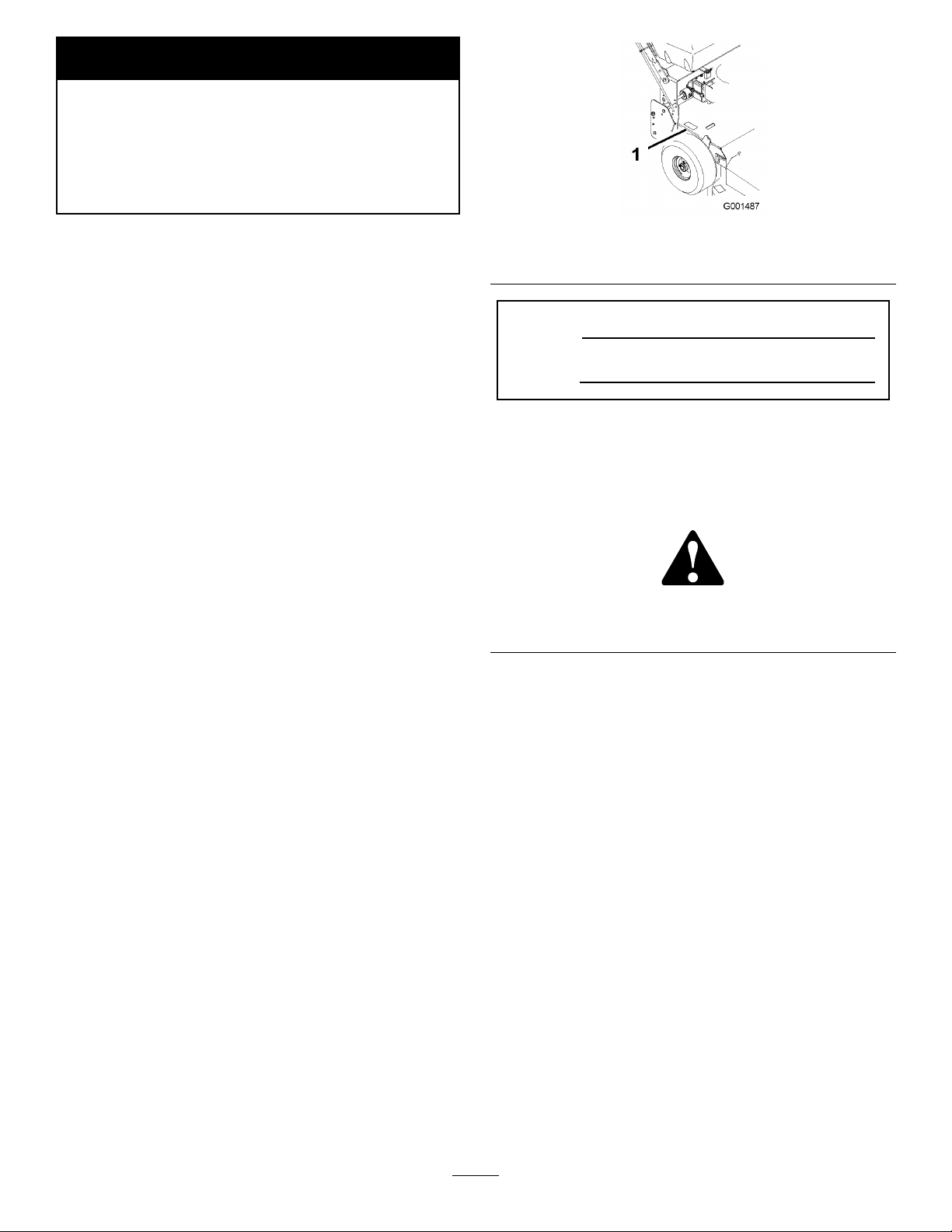
Figure1identiesthelocationofthemodelandserial
numbersontheproduct.Writethenumbersinthe
spaceprovided.
Figure1
1.Modelandserialnumberlocation
ModelNo.
SerialNo.
Thismanualidentiespotentialhazardsandhas
safetymessagesidentiedbythesafetyalertsymbol
(Figure2),whichsignalsahazardthatmaycauseserious
injuryordeathifyoudonotfollowtherecommended
precautions.
Figure2
1.Safetyalertsymbol
Thismanualuses2otherwordstohighlightinformation.
Importantcallsattentiontospecialmechanical
informationandNoteemphasizesgeneralinformation
worthyofspecialattention.
Contents
Introduction.................................................................2
Safety...........................................................................3
SafeOperatingPractices.......................................3
ToroMowerSafety...............................................4
SlopeChart..........................................................6
SafetyandInstructionalDecals.............................7
Setup..........................................................................10
1CheckingtheFluidsandTirePressure..............10
2ReadingtheManualandViewingtheSafety
Information...................................................10
ProductOverview......................................................11
Controls.............................................................11
Specications.....................................................12
Attachments/Accessories...................................12
Operation...................................................................13
©2007—TheToro®Company
8111LyndaleAvenueSouth
Bloomington,MN55420
Contactusatwww.Toro.com.
2
PrintedintheUSA.
AllRightsReserved
Page 3

AddingFuel.......................................................13
ThinkSafetyFirst...............................................14
OperatingtheParkingBrake...............................14
StartingandStoppingtheEngine........................14
OperatingtheBladeControlLever
(PTO)............................................................15
TheSafetyInterlockSystem................................16
DrivingForwardorBackward.............................16
UsingtheLowerControlBar..............................16
StoppingtheMachine.........................................17
TransportingMachines.......................................18
SideDischargingorMulchingtheGrass..............18
AdjustingtheHeight-of-Cut...............................18
AdjustingtheHandleHeight..............................19
HeightofCutChart............................................21
Maintenance...............................................................22
RecommendedMaintenanceSchedule(s)................22
Lubrication.............................................................22
HowtoGrease...................................................22
LubricatingtheCasterandWheel
Bearings.........................................................23
GreasingtheTransmissionCouplers...................23
GreasingtheMowerBeltIdler............................23
EngineMaintenance...............................................24
ServicingtheAirCleaner....................................24
ServicingtheEngineOil.....................................25
ServicingtheSparkPlugs....................................26
FuelSystemMaintenance.......................................28
ServicingtheFuelTank......................................28
ServicingtheFuelFilter......................................28
DriveSystemMaintenance.....................................29
CheckingtheTirePressure.................................29
CoolingSystemMaintenance..................................30
CleaningtheAirIntakeScreen............................30
CleaningtheCoolingSystem...............................30
BrakeMaintenance.................................................30
ServicingtheBrakes...........................................30
BeltMaintenance....................................................31
CheckingtheBelts..............................................31
ReplacingtheTractionDriveBelt........................31
ReplacingtheTransmissionDriveBelt................31
ReplacingtheMowerBelt...................................32
AdjustingtheMowerBeltTension......................33
MowerDeckMaintenance......................................34
ServicingtheCuttingBlades...............................34
AdjustingtheBladeBrake...................................36
ReplacingtheGrassDeector.............................36
Storage.......................................................................37
Troubleshooting.........................................................39
Schematics.................................................................41
Safety
Note:Theadditionofattachmentsmadeby
othermanufacturersthatdonotmeetAmerican
NationalStandardsInstitutecerticationwillcause
noncomplianceofthismachine.
Improperuseormaintenancebytheoperatororowner
canresultininjury.T oreducethepotentialforinjury,
complywiththesesafetyinstructionsandalwayspay
attentiontothesafetyalertsymbol,whichmeans
CAUTION,WARNING,orDANGER-“personalsafety
instruction."Failuretocomplywiththeinstructionmay
resultinpersonalinjuryordeath.
SafeOperatingPractices
ThefollowinginstructionsarefromANSIstandard
B71.4-2004.
Training
•ReadtheOperator’sManualandothertraining
material.Iftheoperator(s)ormechanic(s)cannot
readEnglishitistheowner’ sresponsibilitytoexplain
thismaterialtothem.
•Becomefamiliarwiththesafeoperationofthe
equipment,operatorcontrols,andsafetysigns.
•Alloperatorsandmechanicsshouldbetrained.The
ownerisresponsiblefortrainingtheusers.
•Neverletchildrenoruntrainedpeopleoperateor
servicetheequipment.Localregulationsmayrestrict
theageoftheoperator.
•Theowner/usercanpreventandisresponsiblefor
accidentsorinjuriesoccurringtohimselforherself,
otherpeopleorproperty.
Preparation
•Evaluatetheterraintodeterminewhataccessories
andattachmentsareneededtoproperlyand
safelyperformthejob.Onlyuseaccessoriesand
attachmentsapprovedbythemanufacturer.
•Wearappropriateclothingincludinghardhat,safety
glassesandhearingprotection.Longhair,loose
clothingorjewelrymaygettangledinmovingparts.
•Inspecttheareawheretheequipmentistobeused
andremoveallobjectssuchasrocks,toysandwire
whichcanbethrownbythemachine.
•Useextracarewhenhandlinggasolineandother
fuels.Theyareammableandvaporsareexplosive.
–Useonlyanapprovedcontainer
3
Page 4

–Neverremovegascaporaddfuelwithengine
running.Allowenginetocoolbeforerefueling.
Donotsmoke.
–Neverrefuelordrainthemachineindoors.
•Checkthatoperator’spresencecontrols,safety
switchesandshieldsareattachedandfunctioning
properly.Donotoperateunlesstheyarefunctioning
properly.
•Beawareofthemowerdischargedirectionanddo
notpointitatanyone.
•Donotoperatethemowerundertheinuenceof
alcoholordrugs.
•Usecarewhenloadingorunloadingthemachine
intoorfromatrailerortruck.
•Usecarewhenapproachingblindcorners,shrubs,
trees,orotherobjectsthatmayobscurevision.
Operation
•Neverrunanengineinanenclosedarea.
•Onlyoperateingoodlight,keepingawayfromholes
andhiddenhazards.
•Besurealldrivesareinneutralandparkingbrakeis
engagedbeforestartingengine.Onlystartengine
fromtheoperator’sposition.
•Besureofyourfootingwhileusingthismachine,
especiallywhenbackingup.Walk,don’trun.Never
operateonwetgrass.Reducedfootingcouldcause
slipping.
•Slowdownanduseextracareonhillsides.Besure
totravelsidetosideonhillsides.Turfconditions
canaffectthemachine’ sstability.Usecautionwhile
operatingneardrop-offs.
•Slowdownandusecautionwhenmakingturnsand
whenchangingdirectionsonslopes.
•Neverraisedeckwiththebladesrunning.
•NeveroperatewiththePTOshield,orotherguards
notsecurelyinplace.Besureallinterlocksare
attached,adjustedproperly,andfunctioningproperly.
•Neveroperatewiththedischargedeectorraised,
removedoraltered,unlessusingagrasscatcher.
•Donotchangetheenginegovernorsettingor
overspeedtheengine.
•Stoponlevelground,disengagedrives,engage
parkingbrake(ifprovided),shutoffenginebefore
leavingtheoperator’spositionforanyreason
includingemptyingthecatchersoruncloggingthe
chute.
•Stopequipmentandinspectbladesafterstriking
objectsorifanabnormalvibrationoccurs.Make
necessaryrepairsbeforeresumingoperations.
•Keephandsandfeetawayfromthecuttingunit.
•Lookbehindanddownbeforebackinguptobesure
ofaclearpath.
•Keeppetsandbystandersaway.
•Slowdownandusecautionwhenmakingturnsand
crossingroadsandsidewalks.Stopbladesifnot
mowing.
Maintenanceandstorage
•Disengagedrives,setparkingbrake,stopengineand
removekeyordisconnectsparkplugwire.Waitfor
allmovementtostopbeforeadjusting,cleaningor
repairing.
•Cleangrassanddebrisfromcuttingunit,drives,
mufers,andenginetohelppreventres.Cleanup
oilorfuelspillage.
•Letenginecoolbeforestoringanddonotstorenear
ame.
•Shutofffuelwhilestoringortransporting.Donot
storefuelnearamesordrainindoors.
•Parkmachineonlevelground.Setparkingbrake.
Neverallowuntrainedpersonneltoservicemachine.
•Usejackstandstosupportcomponentswhen
required.
•Carefullyreleasepressurefromcomponentswith
storedenergy.
•Disconnectthebatteryorremovesparkplugwire
beforemakinganyrepairs.Disconnectthenegative
terminalrstandthepositivelast.Reconnectthe
positiverstandnegativelast.
•Usecarewhencheckingblades.Wraptheblade(s)or
weargloves,andusecautionwhenservicingthem.
Onlyreplaceblades.Neverstraightenorweldthem.
•Keephandsandfeetawayfrommovingparts.If
possible,donotmakeadjustmentswiththeengine
running.
•Keepallpartsingoodworkingconditionandall
hardwaretightened.Replaceallwornordamaged
decals.
ToroMowerSafety
Thefollowinglistcontainssafetyinformationspecic
toToroproductsandothersafetyinformationyoumust
know .
Thisproductiscapableofamputatinghandsand
feetandthrowingobjects.Alwaysfollowallsafety
instructionstoavoidseriousinjuryordeath.
4
Page 5

Thisproductisdesignedforcuttingandrecyclinggrass
or,whenequippedwithagrassbagger,forcatching
cutgrass.Anyuseforpurposesotherthanthesecould
provedangeroustouserandbystanders.
GeneralOperation
•Besuretheareaisclearofotherpeoplebefore
mowing.Stopthemachineifanyoneentersthearea.
•Donottouchequipmentorattachmentpartswhich
maybehotfromoperation.Allowtocoolbefore
attemptingtomaintain,adjustorservice.
•UseonlyToro-approvedattachments.Warrantymay
bevoidedifusedwithunapprovedattachments.
•Checkcarefullyforoverheadclearances(i.e.
branches,doorways,electricalwires)before
operatingunderanyobjectsanddonotcontact
them.
SlopeOperation
•Useonlygenuinereplacementpartstoensurethat
originalstandardsaremaintained.
•Checkbrakeoperationfrequently.Adjustandservice
asrequired.
Allslopesandrampsrequireextracaution.Ifyoufeel
uneasyonaslope,donotmowit.
•Removeobstaclessuchasrocks,treelimbs,etc.from
themowingarea.
•Watchforholes,rutsorbumps.Tallgrasscanhide
obstacles.
•Usecautionneardrop-offs,ditches,orembankments.
Themachinecouldsuddenlyturnoverifawheel
goesovertheedgeofaclifforditch,orifanedge
cavesin.
•Useextracarewithgrasscatchersorother
attachments.Thesecanchangethestabilityofthe
machine.
•Keepallmovementonslopesslowandgradual.Do
notmakesuddenchangesinspeedordirection.
•Mowslopessidetoside.
•Donotmowslopesgreaterthan15degrees.
Service
•Neverstorethemachineorfuelcontainerinside
wherethereisanopename,suchasnearawater
heaterorfurnace.
•Keepnutsandboltstight,especiallytheblade
attachmentboltsandnuts.Keepequipmentingood
condition.
•Nevertamperwithsafetydevices.Checksafety
systemsforproperoperationbeforeeachuse.
5
Page 6
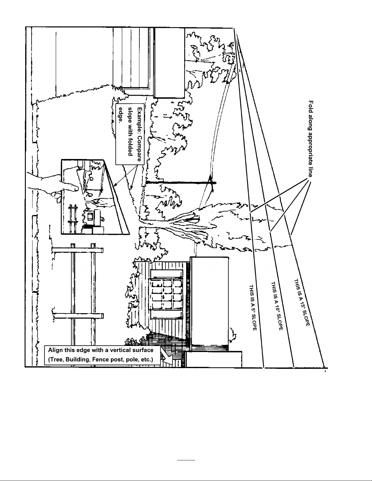
SlopeChart6SafetyandInstructional
Decals
Page 7

82- 2280
REV E R SE TRACT ION DR I V E
Safetydecalsandinstructionsareeasilyvisibletotheoperatorandarelocatednearanyareaof
potentialdanger.Replaceanydecalthatisdamagedorlost.
43-8480
95-5537
1.ReadtheOperator’s
Manualforinstructionson
operatingthecuttingblade
2.Pushforwardtoengage
3.Pullbacktodisengage
66-1340
98-0776
82-2280
98-3256
82-2290
95-2814
7
Page 8

1.Warning—wearhearingprotection.
98-5954
98-3266
98-3296
98-4387
104-8569
98-5130
1.Warning—readtheOperator’sManualforinstructionson
torquingthebladebolt/nutto75-80ft-lb(102-106N⋅m).
106-0699
105-0884
8
Page 9
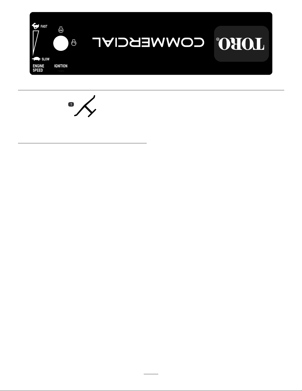
Manufacturer’sMark
1.Indicatesthebladeisidentiedasapartfromtheoriginal
machinemanufacturer.
110-6916
9
Page 10

Setup
LooseParts
Usethechartbelowtoverifythatallpartshavebeenshipped.
ProcedureDescription
1
2
Note:Determinetheleftandrightsidesofthemachinefromthenormaloperatingposition.
Nopartsrequired
Operator’sManual
EngineOperator’sManual
PartsCatalog
SafetyVideo/DVD
RegistrationCard
Oildrainhose
1
CheckingtheFluidsandTire
Pressure
NoPartsRequired
ReadingtheManualand
ViewingtheSafetyInformation
Partsneededforthisprocedure:
Qty.
–
1
1
1
1
1
1
2
Use
Checktheuidsandtirepressure.
ReadtheOperator’sManualandwatch
thevideobeforeoperatingthemachine.
Procedure
•Beforeyoustarttheengineandusethemachine,
checktheoillevelintheenginecrankcase;referto
CheckingtheEngineOilLevel.
•Checkthegreaseforthemowerandmowerdeck.
•Checkthetirepressure;refertoCheckingtheTire
Pressure.
Note:Thecuttingbladesaresettoa3inch(76mm)
height-of-cutatinitialpurchase.TheaxlepositionisD,
with4spacersbelowboththespindleandthecaster.
1
Operator’sManual
1
EngineOperator’sManual
1
PartsCatalog
1
SafetyVideo/DVD
1
RegistrationCard
1
Oildrainhose
Procedure
•ReadtheOperator’sManual.
•Viewthesafetyvideo.
•Fillouttheregistrationcardandmailitinorregister
onlineatwww .Toro.com.
•Usetheoildrainhosewhenchangingtheengineoil.
10
Page 11
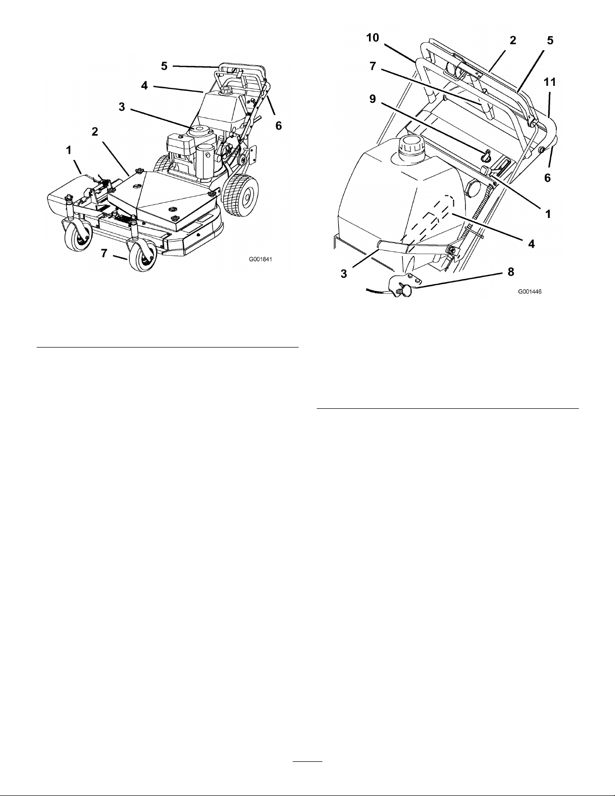
ProductOverview
Figure3
1.Sidedischarge
2.Mowerdeck6.Handle
3.Recoilstarter7.Frontcasterwheel
4.Gastank
Controls
Becomefamiliarwithallthecontrols(Figure4)before
youstarttheengineandoperatethemachine.
5.T-barcontrol
Figure4
1.Throttlecontrol7.Parkingbrake
2.Bladecontrolbail
3.Powertakeofflever(PTO)
4.Gearshiftlever
5.Uppercontrolbar11.Lowerhandle
6.Lowercontrolbar
lever-releasedposition
8.Choke
9.Ignitionswitch
10.Upperhandle
ThrottleControl
Thethrottlecontrolhastwopositions:FastandSlow.
BladeControlBail
Thebailisusedinconjunctionwiththebladecontrol
lever(PTO)toengagetheclutchanddrivethemower
blades.Releasingthebladecontrolbailwillstopthe
enginewiththePTOengaged.
BladeControlLever(PTO)
Thisleverisusedinconjunctionwiththebladecontrol
bailtoengageanddisengagethemowerdeckbeltand
drivethemowerblades.
GearShiftLever
Thetransmissionhasveforwardspeeds,neutraland
reverse,andhasanin-lineshiftpattern.
Important:Donotshiftwhileunitismoving,as
transmissiondamagemayoccur.
11
Page 12

UpperControlBar
Shifttothedesiredgearandpushforwardontheupper
controlbarandbladecontrolbailtoengageforward
tractionoperationandpullbacktobrakeforward
movement.Pullbackonrightsideofuppercontrolbar
toturnrightandleftsidetoturnleft.
LowerControlBar
Shifttransmissiontoreverseandsqueezethelower
controlbarandhandletogethertoengagetherearward
tractionassist.
ParkingBrakeLever
Pullbackonuppercontrolbarandswingbrakelever
upagainsttheupperhandletosettheparkingbrake
(Figure4).
IgnitionSwitch
Thisswitchisusedinconjunctionwithrecoilstarterand
hastwopositions:RunandOff.
Height
Weight
41inches(104.1cm)
460lb(209kg)
Attachments/Accessories
AselectionofToroapprovedattachmentsand
accessoriesareavailableforusewiththemachineto
enhanceandexpanditscapabilities.Contactyour
AuthorizedServiceDealerorDistributororgoto
www.Toro.comforalistofallapprovedattachments
andaccessories.
RecoilStarter
Pullrecoilstarterhandletostartengine(notshownin
Figure4).
FuelShut-offValve
Closethefuelshut-offvalvewhentransportingor
storingmower.
Choke
Usethechoketostartacoldengine.
Specications
Note:Specicationsanddesignaresubjecttochange
withoutnotice.
32inchmowers:
Widthwithdeectordown45.8inches(1 16.3cm)
Length
Height
Weight
72inches(183cm)
41inches(104.1cm)
400lb(181kg)
36inchmowers:
Widthwithdeectordown46.6inches(1 18.4cm)
Length
74inches(188cm)
12
Page 13

Operation
AddingFuel
UseUnleadedRegularGasolinesuitablefor
automotiveuse(85pumpoctaneminimum).Leaded
regulargasolinemaybeusedifunleadedregularisnot
available.
Important:Neverusemethanol,gasoline
containingmethanol,orgasoholcontainingmore
than10%ethanolbecausethefuelsystemcouldbe
damaged.Donotmixoilwithgasoline.
Incertainconditions,gasolineisextremely
ammableandhighlyexplosive.Areor
explosionfromgasolinecanburnyouand
othersandcandamageproperty.
•Fillthefueltankoutdoors,inanopenarea,
whentheengineiscold.Wipeupany
gasolinethatspills.
•Neverllthefueltankinsideanenclosed
trailer.
•Donotllthefueltankcompletelyfull.Add
gasolinetothefueltankuntilthelevelis1/4
to1/2inch(6to13mm)belowthebottomof
thellerneck.Thisemptyspaceinthetank
allowsgasolinetoexpand.
Incertainconditionsduringfueling,static
electricitycanbereleasedcausingaspark
whichcanignitethegasolinevapors.Are
orexplosionfromgasolinecanburnyouand
othersandcandamageproperty.
•Alwaysplacegasolinecontainersonthe
groundawayfromyourvehiclebeforelling.
•Donotllgasolinecontainersinsidea
vehicleoronatruckortrailerbedbecause
interiorcarpetsorplastictruckbedliners
mayinsulatethecontainerandslowtheloss
ofanystaticcharge.
•Whenpractical,removegas-powered
equipmentfromthetruckortrailerand
refueltheequipmentwithitswheelsonthe
ground.
•Ifthisisnotpossible,thenrefuelsuch
equipmentonatruckortrailerfroma
portablecontainer,ratherthanfroma
gasolinedispensernozzle.
•Ifagasolinedispensernozzlemustbeused,
keepthenozzleincontactwiththerimof
thefueltankorcontaineropeningatall
timesuntilfuelingiscomplete.
•Neversmokewhenhandlinggasoline,and
stayawayfromanopenameorwhere
gasolinefumesmaybeignitedbyaspark.
•Storegasolineinanapprovedcontainerand
keepitoutofthereachofchildren.Never
buymorethana30-daysupplyofgasoline.
•Donotoperatewithoutentireexhaust
systeminplaceandinproperworking
condition.
Gasolineisharmfulorfatalifswallowed.
Long-termexposuretovaporscancauseserious
injuryandillness.
•Avoidprolongedbreathingofvapors.
•Keepfaceawayfromnozzleandgastankor
conditionerbottleopening.
•Keepgasawayfromeyesandskin.
UsingStabilizer/Conditioner
Useafuelstabilizer/conditionerinthemachineto
providethefollowingbenets:
•Keepsgasolinefreshduringstorageof90daysor
less.Forlongerstorageitisrecommendedthatthe
fueltankbedrained.
•Cleanstheenginewhileitruns
•Eliminatesgum-likevarnishbuildupinthefuel
system,whichcauseshardstarting
13
Page 14
Important:Donotusefueladditives
containingmethanolorethanol.
Addthecorrectamountofgas
stabilizer/conditionertothegas.
Note:Afuelstabilizer/conditionerismost
effectivewhenmixedwithfreshgasoline.To
minimizethechanceofvarnishdepositsinthefuel
system,usefuelstabilizeratalltimes.
FillingtheFuelTank
1.Shuttheengineoffandsettheparkingbrake.
2.Cleanaroundfueltankcapandremovethecap.
Addunleadedregulargasolinetofueltank,untilthe
levelis1/4to1/2inch(6to13mm)belowthe
bottomofthellerneck.Thisspaceinthetank
allowsgasolinetoexpand.Donotllthefueltank
completelyfull.
3.Installfueltankcapsecurely.Wipeupanygasoline
thatmayhavespilled.
ThinkSafetyFirst
Carefullyreadallthesafetyinstructionsanddecalsin
thesafetysection.Knowingthisinformationcould
helpyouoranybystandersavoidinjury.
Childrenorbystandersmaybeinjuredifthey
moveorattempttooperatethemachinewhile
itisunattended.
Alwaysremovetheignitionkeyandsetthe
parkingbrakewhenleavingthemachine
unattended,evenifjustforafewminutes.
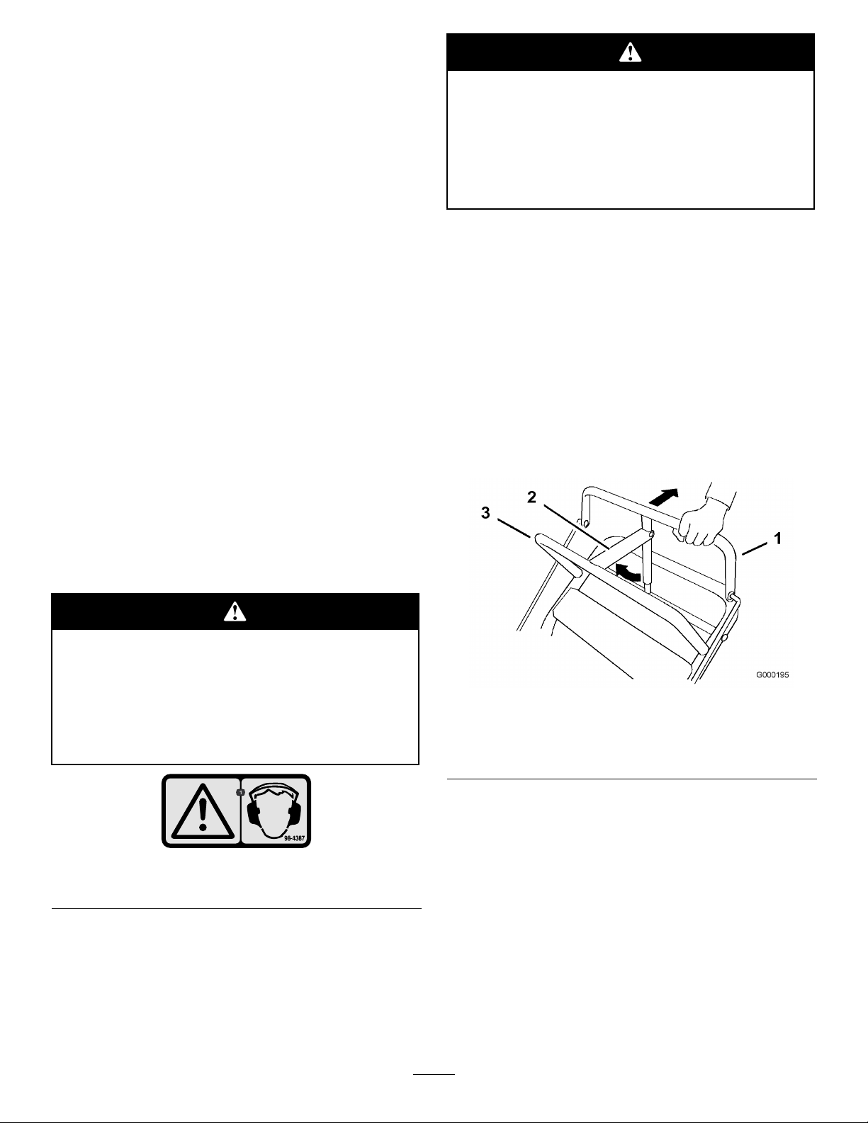
SettingtheParkingBrake
1.Pulltheuppercontrolbarrearwardandholditin
thisposition(Figure6).
2.Lifttheparkingbrakelockupandgraduallyrelease
theuppercontrolbar.Thebrakelockshouldstayin
theset(locked)position(Figure6).
ReleasingtheParkingBrake
1.Pullrearwardontheuppercontrolbar.Lowerthe
parkingbrakelocktothereleasedposition.
2.Graduallyreleasetheuppercontrolbar.
Theuseofprotectiveequipmentforeyes,hearing,feet
andheadisrecommended.
Thismachineproducessoundlevelsinexcess
of85dBAattheoperator’searandcancause
hearinglossthroughextendedperiodsof
exposure.
Wearhearingprotectionwhenoperatingthis
machine.
Figure5
1.Warning—wearhearingprotection.
OperatingtheParkingBrake
Stoponlevelground,disengagedrives,engageparking
brake,shutoffengineandremovekey.Alwayssetthe
parkingbrakewhenyoustopthemachineorleaveit
unattended.
Figure6
1.Uppercontrolbar3.Fixedbar
2.Parkingbrakelever-set
position
StartingandStoppingthe
Engine
StartingtheEngine
1.Connectthewirestothesparkplugs.
2.Openthefuelvalve.
3.Disengagethebladecontrol(PTO)leverandmove
theshiftlevertotheneutralposition.
4.Settheparkingbrakes.
5.Turntheignitionkeytotherunposition(Figure7).
14
Page 15

6.Tostartacoldengine,movethethrottlecontrol
midwaybetweenthefastandslowpositions.
7.Tostartawarmengine,movethethrottlecontrol
tothefastposition.
8.Pullthechokeknobiftheengineiscold(Figure7).
5.Pullwireoffsparkplug(s)topreventpossibilityof
accidentalstartingbeforestoringorperforming
maintenanceonthemachine.
6.Closethefuelshutoffvalvebeforestoringor
transportingthemachine.
Note:Awarmorhotengineusuallydoesnot
requireanychoking.
9.Grasptherecoilstarterhandlermlyandpullit
outuntilpositiveengagementresults;thenpullthe
handlevigorouslytostarttheengine.Allowthe
ropetorecoilslowly .
Important:Donotpulltherecoilropetoits
limitorreleasethestarterhandlewhenyoupull
outtheropebecausetheropemaybreakorthe
recoilassemblymaybedamaged.
10.Pushthechoketooffastheenginewarmsup.
11.Iftheengineiscold,allowittowarmupandthen
movethethrottlecontroltothefastposition.
StoppingtheEngine
Important:Inanemergency ,youcanstopthe
engineimmediatelybyturningtheignitionkeyto
the
of f
position.
1.Movethethrottlelevertotheslowposition
(Figure7).
Important:Makesurefuelshutoffvalveis
closedbeforetransportingorstoringmachine,
asfuelleakagemayoccur.
OperatingtheBladeControl
Lever(PTO)
Thebladecontrollever(PTO)engagesanddisengages
powertothemowerblades.
EngagingtheMowerBlades
1.Toengagetheblades,squeezebladecontrolbail
againsttheuppercontrolbar(Figure8).
2.Pushthebladecontrolleverrmlyforward,untilit
latchesover-center.
3.Restarttheengineandrepeattheprocedureto
engagethemowerbladesifthebladecontrolbail
isreleased.
2.Letengineidlefor30to60secondsbeforeturning
theignitionkeytooff.
3.Turntheignitionkeytooff(Figure7).
Figure7
1.Bladecontrollever(PTO)
2.Throttlelever
3.Ignitionkey
4.Settheparkingbrakeandremovekey.
Figure8
1.Uppercontrolbar
2.Bladecontrolbail
3.Bladecontrollever(PTO)
DisengagingtheMowerBlades(PTO)
Todisengagetheblades,pullthebladecontrollever
rearwardalltheway(Figure8).Theenginewillkill
whenthebladecontrolbailisreleasedwiththeblade
controlleverengaged.
15
Page 16

Note:Itisnecessarytofullyandmanuallydisengage
thebladecontrollever.
throttlecontrolinthefastpositionforbestmowing
performance.
TheSafetyInterlockSystem
Ifsafetyinterlockswitchesaredisconnected
ordamagedthemachinecouldoperate
unexpectedlycausingpersonalinjury.
•Donottamperwiththeinterlockswitches.
•Checktheoperationoftheinterlock
switchesdailyandreplaceanydamaged
switchesbeforeoperatingthemachine.
Thesafetyinterlocksystemisdesignedtopreventthe
enginefromstartingwhen:
•Thebladecontrollever(PTO)isengaged.
•Theignitionkeyisoff.
Thesafetyinterlocksystemisalsodesignedtostopthe
enginewhen:
•Thebladecontrolbailisreleasedwiththeblade
controllever(PTO)engaged.
DrivingForward
1.Togoforward,movetheshiftlevertoaforward
gear(Figure9).
2.Releasetheparkingbrake;refertoReleasingthe
ParkingBrake.
3.Slowlypressontheuppercontrolbartomove
forward(Figure9).
Togostraight,applyequalpressuretobothendsof
theuppercontrolbar(Figure9).
Toturn,releasepressureontheuppercontrolbar
sideinthedirectionyouwanttoturn(Figure9).
•Theignitionswitchisturnedtotheoffposition.
TestingtheSafetyInterlockSystem
Testthesafetyinterlocksystembeforeyouusethe
machineeachtime.Ifthesafetysystemdoesnot
operateasdescribedbelow ,haveanAuthorizedService
Dealerrepairthesafetysystemimmediately .
1.Settheparkingbrake,disengagethePTOandplace
thethrottleforward.
2.Starttheengine.
3.Withtheenginerunningsqueezethebladecontrol
bailagainstuppercontrolbarandpushthemower
bladecontrolleverforward.Themowerblades
beginrotating.
4.Withtheenginerunning,releasethebladecontrol
bail.Theengineshouldstop.
5.Starttheengineagain.
6.Withtheenginerunning,turnthekeyswitchtothe
offposition.Theengineshouldstop.
DrivingForwardorBackward
Thethrottlecontrolregulatestheenginespeedas
measuredinRPM(revolutionsperminute).Placethe
Figure9
1.Uppercontrolbar
2.Lowercontrolbar4.Lowerhandle
3.Shiftlever
DrivingBackward
1.Togobackward,movetheshiftlevertoreversegear.
2.Releasetheparkingbrake;refertoReleasingthe
ParkingBrake.
3.Slowlysqueezethelowercontrolbarandlower
handletogethertomoverearward(Figure9).
UsingtheLowerControlBar
Thisprocedureisfordrivingupacurb.Thiscanbe
performedwhiledrivingforwardorbackward.
Note:Somecurbsdonotallowthereardrivetiresto
contactthecurb.Ifthishappens,drivethemachineup
thecurbatanangle.
16
Page 17

Abladecanbebentordamagedwhendriving
upacurb.Piecesofbladethatmaybethrown
couldseriouslyinjureorkillyouorbystanders.
Donotrunbladeswhiledrivingupacurb
forwardorbackward.
DrivingBackwardUpaCurb
1.Disengagethemowerblades.
2.Selectreversetodrivethemachine.
3.Drivethemachineuntildrivewheelscontactcurb
(Figure10).
Note:Bothdrivewheelsshouldcontactthecurb
andcasterwheelsstraight.
DrivingForwardUpaCurb
1.Disengagethemowerblades.
2.Selectrstgeartodrivethemachine.
3.Drivemachineuntilthecastorwheelscontactcurb
(Figure10).
4.Liftthefrontofthemachinebypushingdownon
thelowerhandle(Figure10).
5.Drivethemachineuntildrivewheelscontactthe
curb(Figure10).
6.Lowerthefrontofthemachine(Figure10).
Note:Bothdrivewheelsshouldcontactthecurb
andcasterwheelsstraight.
7.Atthesametimeengagethelowercontrolbarand
liftuponthelowerhandletodriveoverthecurb
(Figure9andFigure10).
Note:Liftinguponthelowerhandlewillassist
drivingthemachineupacurbandnotspinthe
drivewheels.
4.Atthesametimeengagelowercontrolbarandlift
uponthelowerhandle(Figure9andFigure11).
Note:Liftinguponthelowerhandlewillassist
drivingthemachineupacurbandnotspinthe
drivewheels.
Figure11
1.Lowercontrolbar
(engaged)
2.Handle
1.LowerControlBar
engagedandmower
inreverse.
2.Pulluptoassistmachine
Figure10
3.LowerControlBar
engagedandmower
goingforward.
StoppingtheMachine
Tostopthemachine,pullbackontheuppercontrol
bar,releasethebladecontrolbail,turntheignitionkey
tooffandsettheparkingbrake;refertoSettingthe
ParkingBrakeinOperation,page13.Rememberto
removethekeyfromtheignitionswitch.
Childrenorbystandersmaybeinjuredifthey
moveorattempttooperatethemachinewhile
itisunattended.
Alwaysremovetheignitionkeyandsetthe
parkingbrakewhenleavingthemachine
unattended,evenifjustforafewminutes.
17
Page 18

TransportingMachines
AdjustingtheBladeHeight
Useaheavy-dutytrailerortrucktotransportthe
machine.Ensurethatthetrailerortruckhasall
necessarylightingandmarkingasrequiredbylaw .
Pleasecarefullyreadallthesafetyinstructions.
Knowingthisinformationcouldhelpyou,yourfamily ,
petsorbystandersavoidinjury.
Totransportthemachine:
1.Stoptheengine,removethekey,setthebrake,and
closethefuelvalve.
2.Securelyfastenthemachinetothetrailerortruck
withstraps,chains,cable,orropes.
3.Ifusingatrailer,securethetrailertothetowing
vehicleandinstallthesafetychains.
SideDischargingorMulching
theGrass
Thismowerhasahingedgrassdeectorthatdisperses
clippingstothesideanddowntowardtheturf.
Adjustthebladesbyusingthe4spacers(1/4inch)
(6mm)onthebladespindlebolts.Thisallowsfora
1-inch(25mm)adjustmentrange,in1/4inch(6mm)
increments,ofcuttingheightinanyaxleposition.Use
thesamenumberofbladespacersonallbladesto
achievealevelcut(2aboveand2below,1aboveand3
below,etc.).
1.Disengagethebladecontrol(PTO)leverandset
theparkingbrakes.
2.Stoptheengineandwaitforallmovingpartsto
stopbeforeleavingtheoperatingposition.
3.Holdthebladeboltandremovethenut(Figure12).
Withoutthegrassdeector,dischargecover,
orcompletegrasscatcherassemblymounted
inplace,youandothersareexposedtoblade
contactandthrowndebris.Contactwith
rotatingmowerblade(s)andthrowndebriswill
causeinjuryordeath.
•Neverremovethegrassdeectorfrom
themowerbecausethegrassdeector
routesmaterialdowntowardtheturf.Ifthe
grassdeectoriseverdamaged,replaceit
immediately.
•Neverputyourhandsorfeetunderthe
mower.
•Nevertrytocleardischargeareaormower
bladesunlessyoureleasethebailandthe
powertakeoff(PTO)isoff.Rotatethe
ignitionkeytoOff.Alsoremovethekeyand
pullthewiresoffthesparkplug(s).
AdjustingtheHeight-of-Cut
Thismachinehasa1to4-1/4inch(26to108mm)
rangefortheheight-of-cut.Thiscanbeachievedby
adjustingbladespacers,rearaxleheight,andfront
casterspacers.UsetheHeight-of-CutCharttoselect
thecombinationofadjustmentsrequired.
Figure12
1.Blade
2.Bladebolt5.Thinwasher
3.Curvedwasher
4.Slidetheboltdownthroughthespindle,andchange
thespacersasneeded(Figure12).
5.Installtheboltandcurvedwasher,addextra
spacer(s),andsecurethemwithathinwasheranda
nut(Figure12).
6.Torquethebladeboltto75-80ft-lb(101-108N•m).
4.Spacer
6.Nut
18
Page 19

AdjustingtheAxleHeight
Adjusttheaxlepositiontotheselectedheight-of-cut
setting.RefertotheHeight-of-CutChart.
1.Disengagethebladecontrol(PTO)leverandset
theparkingbrakes.
2.Stoptheengineandwaitforallmovingpartsto
stopbeforeleavingtheoperatingposition.
3.Loosen,butdonotremove,the2axlepivotbolts
andthe2axleadjustmentbolts(Figure13).
Figure13
1.Axlepivotbolt2.Axleadjustmentbolt
Figure14
1.Latchpin
2.Spacer,3/16inch(5mm)
3.Spacer,1/2inch(13mm)
2.Removethelatchpin,slidethecasterfromthe
support,andchangethespacers(Figure14).
3.Installthecasterinthesupportandinsertthevpin
(Figure14).
AdjustingtheHandleHeight
4.Placeajackundertherearcenteroftheengine
frame.Raisethebackendoftheengineframeup
enoughtoremovethefront2axleadjustmentbolts
(Figure13).
Note:Usejackstandstosupportthemachine.
5.Raiseorlowertheengineframewiththejackso
thatyoucaninstallthefront2axleadjustmentbolts
inthedesiredholelocation(Figure13).
Note:Useataperedpunchtohelpaligntheholes.
6.Tightenall4boltsandlowerthemower.
7.Adjustthecontrolrodsandthebrakelinkages
asrequired.RefertoServicingtheBrakesand
AdjustingtheControlRods.
Important:Youmustadjustthecontrolrods
andthebrakelinkagewhenyouchangethe
axlepositionsforpropertractionandbrake
function.
AdjustingtheCasterPosition
Thehandlepositioncanbeadjustedtomatchthe
operator’sheightpreference.
1.Removehairpincotter,washerandclevispin
securingcontrolrodttingtoidlerbracket
(Figure15).
Figure15
1.Controlrod4.Clevispin
2.Controlrodtting
3.Idlerbracket6.Hairpincotterpin
5.Washer
1.UsingtheHeight-of-CutChart,adjustthecaster
spacerstomatchwiththeaxleholeselected
(Figure14).
2.Loosentheupperangebolts(3/8x1inch)and
angenutsecuringhandletorearframe(Figure16).
19
Page 20

Figure16
1.Upperhandle
2.Rearframe
3.Flangebolt(3/8x1inch)
4.Locknut(3/8inch)
5.Uppermountinghole
6.Lowermountinghole
3.Removethelowerangebolts(3/8x1inch)
andangenutssecuringhandletorearframe
(Figure16).
4.Pivothandletodesiredoperatingpositionand
installlowerangebolts(3/8x1inch)andange
nutsintomountingholes.Tightenallangebolts.
5.Threadrodttingupordownonroduntilproper
positionisattainedandinstallintottingtoidler
bracketwithclevispin,washerandhairpincotter.
6.Checktheparkingbrakeadjustment.Referto
CheckingtheBrakesinBrakeMaintenance,
page30.
20
Page 21

HeightofCutChart
Numberofspacers
1/2inch
AxlePosition
A00
A01
A10
B01
B10
B11
B20
C
C
C
C
D21
D30
D31
D40
E31
E40
E41
(13mm)
11
20
21
30
belowcaster
3/16inch(5
mm)
1inch(26
1–1/8inch
(29mm)
1–3/8inch
(35mm)
1–3/8inch
(35mm)
1–5/8inch
(41mm)
1–3/4inch
(45mm)
2inch(51
1–7/8inch
(48mm)
2–1/8inch
(55mm)
2–1/4inch
(57mm)
2–1/2inch
(64mm)
2–3/8inch
(61mm)
2–1/2inch
(64mm)
2–3/4inch
(70mm)
3inch(76
2–7/8inch
(73mm)
3–1/8inch
(79mm)
3–1/4inch
(82mm)
Numberof1/4inchbladespacersbelowspindle
43210
mm)
mm)
mm)
1–1/4inch
(32mm)
1–3/8inch
(35mm)
1–5/8inch
(41mm)
1–5/8inch
(41mm)
1–7/8inch
(48mm)
2inch(51
mm)
2–1/4inch
(57mm)
2–1/8inch
(54mm)
2–3/8inch
(60mm)
2–1/2inch
(64mm)
2–3/4inch
(70mm)
2–5/8inch
(67mm)
2–3/4inch
(70mm)
3inch(76
mm)
3–1/4inch
(82mm)
3–1/8inch
(79mm)
3–3/8inch
(86mm)
3–1/2inch
(89mm)
1–1/2inch
(38mm)
1–5/8inch
(41mm)
1–7/8inch
(48mm)
1–7/8inch
(48mm)
2–1/8inch
(54mm)
2–1/4inch
(57mm)
2–1/2inch
(64mm)
2–3/8inch
(60mm)
2–5/8inch
(67mm)
2–3/4inch
(70mm)
3inch(76
2–7/8inch
(73mm)
3inch(76
3–1/4inch
(82mm)
3–1/2inch
(89mm)
3–3/8inch
(86mm)
3–5/8inch
(92mm)
3–3/4inch
(95mm)
1–3/4inch
(45mm)
1–7/8inch
(48mm)
2–1/8inch
(54mm)
2–1/8inch
(54mm)
2–3/8inch
(60mm)
2–1/2inch
(64mm)
2–3/4inch
(70mm)
2–5/8inch
(67mm)
2–7/8inch
(73mm)
3inch(76
mm)
mm)
mm)
3–1/4inch
(83mm)
3–1/8inch
(79mm)
3–1/4inch
(82mm)
3–1/2inch
(89mm)
3–3/4inch
(95mm)
3–5/8inch
(92mm)
3–7/8inch
(98mm)
4inch(102
mm)
2inch(51
mm)
2–1/8inch
(54mm)
2–3/8inch
(60mm)
2–3/8inch
(60mm)
2–5/8inch
(67mm)
2–3/4inch
(70mm)
3inch(76
mm)
2–7/8inch
(73mm)
3–1/8inch
(79mm)
3–1/4inch
(83mm)
3–1/2inch
(89mm)
3–3/8inch
(86mm)
3–1/2inch
(89mm)
3–3/4inch
(95mm)
4inch(102
mm)
3–7/8inch
(98mm)
4–1/8inch
(105mm)
4–1/4inch
(108mm)
21
Page 22

Maintenance
Note:Determinetheleftandrightsidesofthemachinefromthenormaloperatingposition.
RecommendedMaintenanceSchedule(s)
MaintenanceService
Interval
Aftertherst8hours
Aftertherst25hours
Beforeeachuseordaily
Every25hours
Every50hours
Every100hours
Every200hours
MaintenanceProcedure
•Changetheengineoil.
•Checkthemowerbelttension.
•Checkthemowerbelttension.
•Checkthesafetysystem.
•Greasethecasterwheelsandcasterpivot.
•Checktheengineoillevel.
•Cleantheairintakescreen.
•Checkthebrakes.
•Inspecttheblades.
•Cleanthemowerdeck.
•Cleanfoamaircleanerelement.
•Greasethemowerbeltidler .
•Checkthepaperaircleanerelement.
•Checkthetirepressure.
•Checkthebelts.
•Checkthemowerbelttension.
•Changetheengineoil.
•Checkthesparkplugs.
•Checkandcleanenginecoolingnsandshrouds.
•Replacethepaperaircleanerelement.
•Replacetheoillter.
•Replacethefuellter.
Every250hours
Every400hours
Beforestorage
•Greasethetransmissioncouplers(moreoftenindirtyordustyconditions).
•Greasethewheelbearings(moreoftenindirtyordustyconditions).
•Paintchippedsurfaces.
•Performallmaintenanceprocedureslistedabovebeforestorage.
Important:Refertoyourengineoperator’smanualforadditionalmaintenanceprocedures.
Ifyouleavethekeyintheignitionswitch,someonecouldaccidentlystarttheengineandseriously
injureyouorotherbystanders.
Removethekeyfromtheignitionanddisconnectthesparkplugwirefromthesparkplug(s)beforeyou
doanymaintenance.Setthewireasidesothatitdoesnotaccidentallycontactthesparkplug.
Lubrication
GreasewithNo.2generalpurposelithiumbaseor
molybdenumbasegrease.
HowtoGrease
1.DisengagethePTOandsettheparkingbrake.
2.Stoptheengine,removethekey,andwaitforall
movingpartstostopbeforeleavingtheoperating
position.
22
Page 23

3.Cleanthegreasettingswitharag.Makesureto
scrapeanypaintoffthefrontofthetting(s).
4.Connectagreaseguntothetting.Pumpgrease
intothettingsuntilgreasebeginstooozeoutof
thebearings.
5.Wipeupanyexcessgrease.
LubricatingtheCasterand
WheelBearings
1.Lubricatethefrontwheelbearingsandfrontspindles
(Figure17).
Note:Removethemowerdeckcovertoaccessthe
greasettingforthemowerbeltidlerarm.
2.Lubricatethedrivewheelbearings(
Figure17
Figure17).
GreasingtheTransmission
Couplers
Lubricatethetransmissioncouplersandidlerarmpivots
locatedinthebackofthemachine(Figure18).
Figure19
Figure18
GreasingtheMowerBeltIdler
Greasethettingonthemowerbeltidlerarmpivot
(Figure19).
23
Page 24

EngineMaintenance
ServicingtheAirCleaner
ServiceInterval/Specication
Foamelement:Cleanitafterevery25operatinghours.
Paperelement:Checkitafterevery50operatinghours.
Replaceitafterevery200operatinghoursoryearly,
whichevercomesrst.
Inspectthefoamandpaperelementsandreplacethem
iftheyaredamagedorexcessivelydirty.
Note:Servicetheaircleanermorefrequently(every
fewoperatinghours)iftheoperatingconditionsare
extremelydustyorsandy .
Important:Donotoilthefoamorpaperelement.
RemovingtheFoamandPaper
Elements
1.DisengagethePTOandsettheparkingbrake.
2.Stoptheengine,removethekey,andwaitforall
movingpartstostopbeforeleavingtheoperating
position.
3.Cleanaroundtheaircleanertopreventdirt
fromgettingintotheengineandcausingdamage
(Figure20).
4.Unscrewthecoverknobandremovetheaircleaner
cover(Figure20).
5.Removethe2wingnutsandremovetheaircleaner
assembly(Figure20).
6.Carefullypullthefoamelementoffthepaper
element(Figure20).
Figure20
1.Engine4.Foamelement
2.Cover
3.Wingnut
5.Paperelement
6.Coverknob
CleaningtheFoamAirCleanerElement
1.Washthefoamelementinliquidsoapandwarm
water.Whentheelementisclean,rinseitthoroughly.
2.Drytheelementbysqueezingitinacleancloth.
Important:Replacethefoamelementifitis
tornorworn.
ServicingthePaperAirCleaner
Element
1.Donotcleanthepaperlter.Replaceitafter200
operatinghours(Figure20).
2.Inspecttheelementfortears,anoilylm,ordamage
totherubberseal.
3.Replacethepaperelementifitisdamaged.
InstallingtheFoamandPaperElements
Important:Topreventenginedamage,always
operatetheenginewiththecompletefoamand
paperaircleanerassemblyinstalled.
1.Carefullyslidethefoamelementontothepaperair
cleanerelement(Figure20).
24
Page 25

2.Placetheaircleanerassemblyontotheaircleaner
baseandsecureitwiththe2wingnuts(Figure20).
3.Placetheaircleanercoverintopositionandtighten
thecoverknob(Figure20).
ServicingtheEngineOil
ServiceInterval/Specication
Changetheengineoilasfollows:
•Aftertherst8operatinghours
•Afterevery100operatinghours
Note:Changetheoilmorefrequentlywhenthe
operatingconditionsareextremelydustyorsandy.
OilType:Detergentoil(APIserviceSF ,SG,SH,
orSJ)
CrankcaseCapacity:58ounces(1.7liter)withthe
lterremoved;51ounces(1.5liter)withoutthelter
removed
Viscosity:Refertothetablein(
Figure21).
Figure22
1.Oildipstick
2.Fillertube
5.Unscrewtheoildipstickandwipetheendclean
(Figure22).
6.Slidetheoildipstickfullyintothellertube,butdo
notthreadontotube(Figure22).
7.Pullthedipstickoutandlookattheend.Iftheoil
levelislow,slowlypouronlyenoughoilintotheller
tubetoraisetheleveltotheFullmark.
Important:Donotoverllthecrankcasewith
oilandruntheengine;enginedamagecan
result.
ChangingtheOil
1.Starttheengineandletitrunveminutes.This
warmstheoilsoitdrainsbetter.
2.Parkthemachinesothatthedrainsideisslightly
lowerthantheoppositesidetoassuretheoildrains
completely.
Figure21
CheckingtheEngineOilLevel
1.Parkthemachineonalevelsurface.
2.DisengagethePTOandsettheparkingbrake.
3.Stoptheengine,removethekey,andwaitforall
movingpartstostopbeforeleavingtheoperating
position.
4.Cleanaroundtheoildipstick(Figure22)sothatdirt
cannotfallintothellerholeanddamagetheengine.
3.DisengagethePTOandsettheparkingbrake.
4.Stoptheengine,removethekey,andwaitforall
movingpartstostopbeforeleavingtheoperating
position.
5.Slidethedrainhoseovertheoildrainvalve.
6.Placeapanbelowthedrainhose.Rotateoildrain
valvetoallowoiltodrain(Figure23).
7.Whenoilhasdrainedcompletely,closethedrain
valve.
8.Removethedrainhose(Figure23).
Note:Disposeoftheusedoilatarecyclingcenter.
25
Page 26

3.Applyathincoatofnewoiltotherubbergasketon
thereplacementlter(Figure24).
4.Installthereplacementoilltertothelteradapter,
turntheoillterclockwiseuntiltherubbergasket
contactsthelteradapter,thentightenthelteran
additional3/4turn(Figure24).
5.Fillthecrankcasewiththepropertypeofnewoil;
refertoServicingtheEngineOil.
6.Runtheengineforabout3minutes,stoptheengine,
andcheckforoilleaksaroundtheoillteranddrain
valve.
7.Checktheengineoillevelandaddoilifneeded.
ServicingtheSparkPlugs
Figure23
1.Oildrainvalve2.Oildrainhose
9.Slowlypourapproximately80%ofthespeciedoil
intothellertube(Figure22).
10.Checktheoillevel;refertoCheckingtheEngineOil
Level.
11.SlowlyaddtheadditionaloiltobringittotheFull
mark.
ChangingtheOilFilter
Replacetheoillterevery200operatinghoursorevery
otheroilchange.
Note:Changetheoilltermorefrequentlywhenthe
operatingconditionsareextremelydustyorsandy .
1.Draintheoilfromtheengine;refertoChangingthe
EngineOil.
2.Removetheoldlter(Figure24).
ServiceInterval/Specication
Checkthesparkplugsafterevery100operatinghours.
Ensurethattheairgapbetweenthecenterandside
electrodesiscorrectbeforeinstallingthesparkplug.
Useasparkplugwrenchforremovingandinstallingthe
sparkplugsandagappingtool/feelergaugetocheckand
adjusttheairgap.Installanewsparkplugsifnecessary.
Type:Champion®RCJ8YorequivalentAirGap:
0.030inch(0.75mm)
RemovingtheSparkPlugs
1.DisengagethePTOandsettheparkingbrake.
2.Stoptheengine,removethekey,andwaitforall
movingpartstostopbeforeleavingtheoperating
position.
3.Disconnectthewiresfromthesparkplugs
(Figure25).
1.Oillter
Figure24
2.Adapter
26
Page 27

Figure25
1.Spark-plugwire/sparkplug
4.Cleanaroundthesparkplugstopreventdirtfrom
fallingintotheengineandpotentiallycausing
damage.
Important:Alwaysreplacethesparkplugs
whenithasablackcoating,wornelectrodes,
anoilylm,orcracks.
3.Checkthegapbetweenthecenterandsideelectrodes
(Figure26).Bendthesideelectrode(Figure26)if
thegapisnotcorrect.
InstallingtheSparkPlugs
1.Installthesparkplugsandthemetalwasher.Ensure
thattheairgapissetcorrectly.
2.Tightenthesparkplugsto16ft-lb(22N•m).
3.Connectthewirestothesparkplugs(Figure26).
5.Removethesparkplugsandthemetalwashers.
CheckingtheSparkPlugs
1.Lookatthecenterofthesparkplugs(Figure26).
Ifyouseelightbrownorgrayontheinsulator,the
engineisoperatingproperly .Ablackcoatingonthe
insulatorusuallymeansthattheaircleanerisdirty.
2.Ifneeded,cleanthesparkplugwithawirebrushto
removecarbondeposits.
Figure26
1.Centerelectrodeinsulator3.Airgap(nottoscale)
2.Sideelectrode
27
Page 28

FuelSystem
Maintenance
ServicingtheFuelTank
Incertainconditions,gasolineisextremely
ammableandhighlyexplosive.Areor
explosionfromgasolinecanburnyouand
othersandcandamageproperty.
•Draingasolinefromthefueltankwhenthe
engineiscold.Dothisoutdoorsinanopen
area.Wipeupanygasolinethatspills.
Figure27
1.Fuelshut-offvalve2.Clamp
•Neversmokewhendraininggasoline,and
stayawayfromanopenameorwherea
sparkmayignitethegasolinefumes.
DrainingtheFuelTank
1.Parkthemachineonalevelsurface,toassurefuel
tankdrainscompletely.Thendisengagethepower
takeoff(PTO),settheparkingbrake,andturnthe
ignitionkeytooff.Removethekey.
2.Closethefuelshut-offvalveatthefueltank
(Figure27).
3.Squeezetheendsofthehoseclamptogether
andslideitupthefuellineawayfromfuellter
(Figure27).
4.Pullthefuellineoffthefuellter(Figure27).Open
thefuelshut-offvalveandallowthegasolinetodrain
intoagascanordrainpan.
Note:Nowisthebesttimetoinstallanewfuellter
becausethefueltankisempty.RefertoReplacing
theFuelFilter.
ServicingtheFuelFilter
Replacethefuellterafterevery200operatinghoursor
yearly,whicheveroccursrst.
ReplacingtheFuelFilter
Neverinstalladirtylterifitisremovedfromthefuel
line.
Note:Notehowthefuellterisinstalledinorderto
installthenewltercorrectly.
Note:Wipeupanyspilledfuel.
1.DisengagethePTOandsettheparkingbrake.
2.Stoptheengine,removethekey,andwaitforall
movingpartstostopbeforeleavingtheoperating
position.
3.Closefuelshut-offvalveatthefueltank(Figure27).
4.Squeezetheendsofthehoseclampstogetherand
slidethemawayfromthelter(Figure28).
5.Installthefuellineontothefuellter.Slidethehose
clampclosetothevalvetosecurethefuelline.
28
Page 29

Figure28
1.Hoseclamp3.Filter
2.Fuelline
5.Removethelterfromthefuellines.
6.Installanewlterandmovethehoseclampsclose
tothelter.
DriveSystem
Maintenance
CheckingtheTirePressure
Checkthepressureatthevalvestemafterevery
50operatinghoursormonthly,whicheveroccursrst
(Figure29).
Maintaintheairpressureinthereartiresat12-14psi
(83-97kPa).Uneventirepressurecancauseanuneven
cut.
Note:Thefronttiresaresemi-pneumatictiresanddo
notrequireairpressuremaintenance.
7.Openfuelshut-offvalveatfueltank(Figure27).
8.Checkforfuelleaksandrepairifneeded.
9.Wipeupanyfuelthatspilled.
Figure29
29
Page 30

CoolingSystem
Maintenance
BrakeMaintenance
ServicingtheBrakes
CleaningtheAirIntakeScreen
Beforeeachuseremoveanybuild-upofgrass,dirt
orotherdebrisfromthecylinderandcylinderhead
coolingns,airintakescreenonywheelend,and
carburetor-governorleversandlinkage.Thiswillhelp
insureadequatecoolingandcorrectenginespeedand
willreducethepossibilityofoverheatingandmechanical
damagetotheengine.
CleaningtheCoolingSystem
Cleantheairintakescreenfromgrassanddebrisbefore
eachuse.
Checkandcleancoolingnsandengineshroudsevery
100hoursoryearly,whichevercomesrst.
1.DisengagethePTOandsettheparkingbrake.
2.Stoptheengine,removethekey,andwaitforall
movingpartstostopbeforeleavingtheoperating
position.
3.Removetheairintakescreen,recoilstarterandfan
housing(Figure30).
4.Cleanthedebrisandgrassfromtheengineparts.
5.Installairintakescreen,recoilstarterandfanhousing
(Figure30).
Beforeeachuse,checkbrakesonbothalevelsurface
andslope.
Alwayssettheparkingbrakewhenyoustopthemachine
orleaveitunattended.Iftheparkingbrakedoesnot
holdsecurely,anadjustmentisrequired.
CheckingtheBrakes
1.Parkthemachineonalevelsurface,disengagethe
bladecontrol(PTO).
2.Stoptheengine,removethekey,andwaitforall
movingpartstostopbeforeleavingtheoperating
position.
3.Applytheparkingbrake.Thewheelsmustlock
whenyoutrytopushthemachineforward.
4.Ifthewheelsdonotlock,adjustthebrakes.Refer
toAdjustingtheBrakes.
5.Releasethebrakeandpressuppercontrolbarvery
lightly,approximately1/2inch(13mm).Thewheels
shouldrotatefreely ,ifnot;refertoAdjustingthe
Brakes.
AdjustingtheBrakes
Thebrakeleverisontheuppercontrolbar.Ifthe
parkingbrakedoesnotholdsecurely ,anadjustmentis
required.
Figure30
1.Airintakescreen4.Bolt
2.Fanhousing5.Nut
3.Recoilstarter
1.Parkthemachineonalevelsurface,disengagethe
PTO,andsettheparkingbrake.
2.Stoptheengine,removethekey,andwaitforall
movingpartstostopbeforeleavingtheoperating
position.
3.Checkthebrakebeforeyouadjustit;referto
CheckingtheBrakes.
4.Releasetheparkingbrake;refertoReleasingthe
ParkingBrakeinOperation,page13.
5.Toadjustthebrake,rotatethewingnutsonthe
brakerods(Figure31).Turnthewingnutsclockwise
totightenthebrakeandcounterclockwisetoloosen
thebrake.
30
Page 31

Figure31
1.Brakerod2.Wingnut
Note:Controlbarshouldbeparallelwiththe
referencebarwhenproperlyadjusted.
6.Checkthebrakeoperationagain;refertoChecking
theBrakes.
Important:Withtheparkingbrakereleased,
therearwheelsmustrotatefreelywhenyou
pushthemower.Ifbrakeactionandfreewheel
rotationcannotbeachievedcontactyourservice
dealerimmediately .
BeltMaintenance
CheckingtheBelts
Checkallbeltsafterevery50operatinghoursor
monthly,whicheveroccursrst.
Lookfordirt,wear,cracksandsignsofoverheating.
ReplacingtheTractionDrive
Belt
1.Removehairpincottersecuringbrakerodtobrake
armtorelaxbeltidlertension(Figure32).
2.Removebottomandloosentopboltsofshieldto
rotateforbeltclearance(Figure32).
3.Liftthebeltpastidlerandoffthedrivepulley
(Figure32).
4.Raisethewheeloffgroundenoughtoallowbelt
removal.
5.Replacethetractiondrivebelt.
6.Secureshieldwithpreviouslyremovedboltand
tightenbolts(Figure32).
7.Securebrakerodtobrakearmwithhairpincotter
(Figure32).
Figure32
1.Hairpincotter
2.Brakerod4.Drivebelt
3.Shield
ReplacingtheTransmission
DriveBelt
1.Disengagethebladecontrol(PTO)leverandsetthe
parkingbrakes.
2.Stoptheengineandwaitforallmovingpartstostop
beforeleavingtheoperatingposition.
3.Raisetherearofthemachineandholditupwith
jackstands.
31
Page 32

4.Removethemowerbelt;refertoReplacingthe
MowerBelt(Figure33).
Figure33
1.Idlerpulleyinslot4.Beltguide
2.Tractionbelt
3.Mowerbelt6.Mowerbelt
5.3/4inch(19mm)
Note:Thepropermowerbelttensionis10-15lbf.
(44-67N)withthebeltdeected1/2inch(13mm)
halfwaybetweenthepulleys(Figure34).
5.Loosenthepivotboltenoughtoslidetheidlerpulley
intheslotandremovethetractionbeltfromthe
engineandthedrivepulleys(Figure33).
6.Installthenewdrivebeltaroundtheengineandthe
drivepulleys(Figure33).
7.Slidetheidlerpulleyintheengineframetotension
thetractionbelt(Figure33).
8.Installthemowerbelt(Figure33).
9.Checkthebeltguideundertheengineframeforthe
properadjustment(Figure33).
Note:Thedistancebetweenthebeltguideand
mowerbeltshouldbe3/4inch(19mm)whenthe
mowerbeltisengaged.Adjustthebeltifnecessary.
Thedisengagedbeltshouldnotdragorfalloffthe
pulleywhentheguidesareproperlyadjusted.
ReplacingtheMowerBelt
1.Disengagethebladecontrol(PTO)leverandsetthe
parkingbrakes.
2.Stoptheengineandwaitforallmovingpartstostop
beforeleavingtheoperatingposition.
Figure34
1.Mowerbeltwith1/2inch
(13mm)deection
2.Idlerpulley
8.Engagethebladecontrol(PTO)lever.
9.Checktheclearancebetweenthebellcrankandthe
transmissionoutputshaft(Figure35).
Figure35
1.1/16-1/8inch(2-3mm)
2.Bellcrank
3.Transmissionoutputshaft6.Clevis
4.Hairpincotter
5.Clevispin
3.Removetheknobsandthebeltcoveronthemower.
4.Removetheidlerpulleyandthewornbelt(Figure34).
5.Installthenewmowerbelt.
6.Installtheidlerpulley.
7.Engagethebladecontrol(PTO)leverandcheck
thebelttension.RefertoAdjustingtheMowerBelt
Tension.
Note:Theclearanceshouldbe1/16—1/8inch
(2-3mm).
10.Removethehairpincotterandtheclevispinfrom
thebellcrank.
11.Rotatetheclevisclockwiseontherodtoincrease
theclearance;rotateitcounterclockwisetodecrease
it(Figure35).
32
Page 33

12.Disengagethebladecontrol(PTO)lever.
Note:Iftheassistarmdoesnotcontactthefront
stoponthemowerdeck(Figure36),adjusttheclevis
tobringthebellcrankclosertothetransmission
outputshaft(Figure35).
Figure37
1.Idlerpulleyinslot4.Beltguide
2.Tractionbelt
3.Mowerbelt6.Mowerbelt
5.1-1/4inch(32mm)
AdjustingtheMowerBelt
Tension
Figure36
1.1/2inch(13mm)deection
here
2.Assistarm5.Turnbuckle
3.Frontstop
4.Locknut
13.Checkthebeltguideundertheengineframeforthe
properadjustment(Figure33).
Note:Thedistancebetweenthebeltguideandthe
mowerbeltshouldbe1-1/4inch(32mm)when
youengagethemowerbelt(Figure37).Adjustthe
mowerbeltasnecessary.Thedisengagedbeltshould
notdragorfalloffthepulleywhentheguidesare
properlyadjusted.
Adjustthemowerbelttensionasfollows:
•Aftertherst8operatinghours.
•Aftertherst25operatinghours.
•Afterevery50operatinghours.
Checkthebelttensionaftertherst8operatinghours
and25operatinghoursthereafter.Checkthebelt
tensionafterevery50operatinghours.
Important:Thebladebrakeneedstobeadjusted
whenthebelttensionorthebrakelinkageis
adjusted.
Important:Thebeltmustbetightenoughtonot
slipduringheavyloadswhilecuttinggrass.Over
tensioningthebeltwillreducethebearinglifeof
thebeltandthespindle.
1.Disengagethebladecontrol(PTO)leverandsetthe
parkingbrakes.
2.Stoptheengineandwaitforallmovingpartstostop
beforeleavingtheoperatingposition.
3.Loosenthelocknutontheturnbuckle(Figure36).
4.Rotatetheturnbuckletowardtherearofthe
mowertoincreasethetensiononthebelt.Rotate
theturnbuckletowardthefrontofthemowerto
decreasethetensiononthebelt(Figure36).
Note:Theeyeboltthreadsonbothendsofthe
turnbuckleshouldbeengagedaminimumof
5/16inch(8mm).
33
Page 34

MowerDeck
Maintenance
ServicingtheCuttingBlades
Toensureasuperiorqualityofcut,keeptheblades
sharp.Forconvenientsharpeningandreplacement,you
maywanttokeepextrabladesonhand.
Awornordamagedbladecanbreak,anda
pieceofthebladecouldbethrownintothe
operator’sorbystander’sarea,resultingin
seriouspersonalinjuryordeath.
•Inspectthebladeperiodicallyforwearor
damage.
•Replaceawornordamagedblade.
BeforeInspectingorServicingthe
Blades
Parkthemachineonalevelsurface,disengagetheblade
controlbailandsettheparkingbrake.Turntheignition
keytooff.Removethekeyanddisconnectthespark
plugwire(s)fromthesparkplug(s).
InspectingtheBlades
Inspectthebladesevery8hours.
1.Inspectthecuttingedges(Figure38).Iftheedges
arenotsharporhavenicks,removeandsharpenthe
blades.RefertoSharpeningtheBlades.
Figure38
1.CuttingEdge3.Wear/slotForming
2.CurvedArea
2.Inspecttheblades,especiallythecurvedarea
(Figure38).Ifyounoticeanydamage,wear,or
aslotforminginthisarea(item3inFigure38),
immediatelyinstallanewblade.
CheckingforBentBlades
1.Rotatethebladesuntiltheendsfaceforwardand
backward(Figure39).
1.Measurefromcuttingedgetoalevelsurface
34
Figure39
Figure40
Page 35

2.Measurefromalevelsurfacetothecuttingedge,
positionA,oftheblades(Figure40).Notethis
dimension.
3.Rotatetheoppositeendsofthebladesforward.
4.Measurefromalevelsurfacetothecuttingedgeof
thebladesatthesamepositionasinstep1.The
differencebetweenthedimensionsobtainedinsteps
1and2mustnotexceed1/8inch(3mm).Ifthis
dimensionexceeds1/8inch(3mm),thebladeis
bentandmustbereplaced.RefertoRemovingthe
BladesandInstallingtheBlades.
Abladethatisbentordamagedcouldbreak
apartandcouldseriouslyinjureorkillyouor
bystanders.
•Alwaysreplacebentordamagedbladewith
anewblade.
•Neverleorcreatesharpnotchesinthe
edgesorsurfacesofblade.
RemovingtheBlades
Replacethebladesifyouhitasolidobjectorifthe
bladesareoutofbalanceorbent.T oensureoptimum
performanceandcontinuedsafetyconformanceof
themachine,usegenuineT ororeplacementblades.
Replacementbladesmadebyothermanufacturersmay
resultinnon-conformancewithsafetystandards.
1.Holdthebladeboltwithawrench.
2.Removethenut,bladebolt,curvedwasher,blade,
spacers,andthinwasherfromthespindle(Figure41).
Figure41
1.Blade
2.Bladebolt5.Thinwasher
3.Curvedwasher
4.Spacer
6.Nut
SharpeningtheBlades
1.Usealetosharpenthecuttingedgeatbothends
oftheblade(Figure42).Maintaintheoriginalangle.
Thebladeretainsitsbalanceifthesameamountof
materialisremovedfrombothcuttingedges.
Figure42
1.Sharpenatoriginalangle
2.Checkthebalanceofthebladebyputtingitona
bladebalancer(Figure43).Ifthebladestaysina
horizontalposition,thebladeisbalancedandcanbe
used.Ifthebladeisnotbalanced,lesomemetaloff
35
Page 36

theendofthesailareaonly(Figure43).Repeatthis
procedureuntilthebladeisbalanced.
Figure43
1.Blade2.Balancer
InstallingtheBlades
1.Installthecurvedwasherandthenthebladeonto
thebolt.Selectthepropernumberofspacer(s)for
theheight-of-cut,andslidetheboltintothespindle
(Figure41).
Important:Thecurvedpartoftheblademust
pointupwardtowardtheinsideofthemowerto
ensurepropercutting.
2.Installtheremainingspacer(s)andsecurethemwith
athinwasherandanut(Figure41).
Figure44
1.Springmountingbolts3.1/8-3/16inch(3mm-5mm)
2.Bladebrakepad
ReplacingtheGrassDeector
3.Torquethebladeboltto75-80ft-lb(101-108N•m).
AdjustingtheBladeBrake
1.DisengagethePTO,turntheignitionkeytooff,and
removethekey.
2.Waitforallmovingpartstostopbeforeleavingthe
operatingpositionandthensettheparkingbrakes.
3.Ifnecessary,adjustthespringmountingboltssothat
thebladebrakepadrubsagainstbothsidesofthe
pulleygroove(Figure44).
4.Adjustthenutattheendofthebladebrakeroduntil
thereis1/8-3/16inch(3mm-5mm)betweenthe
nutandspacer(Figure44).
5.Engagetheblades.Ensurethebladebrakepadno
longercontactsthepulleygroove.
Anuncovereddischargeopeningcouldallow
thelawnmowertothrowobjectsinthe
operator’sorbystander’sdirectionandresultin
seriousinjuryordeath.Also,contactwiththe
bladecouldoccur.
Neveroperatethelawnmowerwiththegrass
deectorremovedunlessyouinstallacover
plate,amulchplate,oragrasschuteand
catcher.
1.Removethelocknut,bolt,springandspacerholding
thedeectortothepivotbrackets(Figure45).
Removedamagedorworngrassdeector.
36
Page 37

Figure45
1.Bolt
2.Spacer6.GrassDeector
3.Locknut
4.Spring8.Jhookendofspring
5.Springinstalled
7.Lendofspring,place
behinddeckedgebefore
installingbolt
Storage
1.Disengagethepowertakeoff(PTO),settheparking
brake,andturntheignitionkeytooff.Removethe
key.
2.Removegrassclippings,dirt,andgrimefromthe
externalpartsoftheentiremachine,especiallythe
engine.Cleandirtandchafffromtheoutsideofthe
engine’scylinderheadnsandblowerhousing.
Important:Youcanwashthemachinewith
milddetergentandwater.Donotpressurewash
themachine.Avoidexcessiveuseofwater,
especiallyneartheshiftleverplate,andengine.
3.Checkthebrake;refertoServicingtheBrakein
BrakeMaintenance,page30.
4.Servicetheaircleaner;refertoServicingtheAir
Cleaner.
5.Greasethemachine;refertoGreasingand
LubricationinLubrication,page22.
6.Changethecrankcaseoil;refertoServicingthe
Enginein.
7.Checkthetirepressure;refertoCheckingtheTire
PressureinDriveSystemMaintenance,page29.
2.Placespacerandspringontograssdeector.Place
theLendofspringbehinddeckedge.
Note:MakesuretheLendofspringisinstalled
behinddeckedgebeforeinstallingtheboltasshown
inFigure45.
3.Installboltandnut.PlacetheJhookendofspring
aroundgrassdeector(Figure45).
Important:Thegrassdeectormustbefree
torotate.Liftthedeectoruptothefullopen
positionandensurethatitrotatesfreelywithout
bindingintothefulldownposition.
8.Forlong-termstorage:
A.Addstabilizer/conditioneradditivetofuelinthe
tank.
B.Runenginetodistributeconditionedfuelthrough
thefuelsystem(5minutes).
C.Stopengine,allowtocoolanddrainthefuel
tank;refertoServicingtheFuelTankinFuel
SystemMaintenance,page28,oroperateengine
untilitstops.
D.Restartengineandrununtilitstops.Repeat,on
Chokeuntilenginewillnotrestart.
E.Disposeoffuelproperly .Recycleasperlocal
codes.
Note:Donotstorestabilizer/conditioned
gasolineover90days.
9.Removethesparkplug(s)andcheckitscondition;
refertoServicingtheSparkPlug.Withthe
sparkplug(s)removedfromtheengine,pour
twotablespoonsofengineoilintothesparkplug
hole.Nowusethestartertocranktheengineand
distributetheoilinsidethecylinder.Installthespark
plug(s).Donotinstallthewireonthesparkplug(s).
10.Checkandtightenallbolts,nuts,andscrews.Repair
orreplaceanypartthatisdamagedordefective.
37
Page 38

11.Paintallscratchedorbaremetalsurfaces.Paintis
availablefromyourAuthorizedServiceDealer.
12.Storethemachineinaclean,drygarageorstorage
area.Removethekeyfromtheignitionswitchand
keepitinamemorableplace.Coverthemachineto
protectitandkeepitclean.
38
Page 39

Troubleshooting
Problem
Enginewillnotstart,startshard,orfails
tokeeprunning.
Enginelosespower.
PossibleCauseCorrectiveAction
1.Fueltankisempty.
2.Fuelshutoffvalveisclosed.2.Openthefuelshutoffvalve.
3.Chokeisnoton.
4.Aircleanerisdirty.
5.Sparkplugwireislooseor
disconnected.
6.Sparkplugispitted,fouled,orthegap
isincorrect.
7.Dirtinthefuellter.7.Replacethefuellter.
8.Dirt,water,orstalefuelisinthefuel
system.
1.Engineloadisexcessive.1.Reducethegroundspeed.
2.Aircleanerisdirty.
3.Oillevelinthecrankcaseislow .
4.Coolingnsandairpassagesunder
theengineblowerhousingareplugged.
5.Sparkplugispitted,fouled,orthegap
isincorrect.
6.Ventholeinthefuelcapisplugged.6.Cleanorreplacethefuelcap.
7.Dirtinthefuellter.7.Replacethefuellter.
8.Dirt,water,orstalefuelisinthefuel
system.
1.Fillthefueltankwithgasoline.
3.Movethethrottlelevertochoke
position.
4.Cleanorreplacetheaircleaner
element.
5.Installthewireonsparkplug.
6.Installanew,correctlygappedspark
plug.
8.ContactanAuthorizedServiceDealer.
2.Cleantheaircleanerelement.
3.Addoiltothecrankcase.
4.Removetheobstructionfromthe
coolingnsandairpassages.
5.Installanew,correctlygappedspark
plug.
8.ContactanAuthorizedServiceDealer.
Engineoverheats.
Machinedoesnotdrive.
Abnormalvibration.
Unevencuttingheight.
1.Engineloadisexcessive.1.Reducethegroundspeed.
2.Oillevelinthecrankcaseislow .
3.Coolingnsandairpassagesunder
theengineblowerhousingareplugged.
1.Shiftleverisinneutral.1.Movetheshiftlevertoadrivegear
2.Tractionbeltisworn,looseorbroken.
3.Tractionbeltisoffapulley.3.Changethebelt.
1.Cuttingblade(s)is/arebentor
unbalanced.
2.Blademountingboltisloose.2.Tightentheblademountingbolt.
3.Enginemountingboltsareloose.3.Tightentheenginemountingbolts.
4.Looseenginepulley,idlerpulley ,or
bladepulley .
5.Enginepulleyisdamaged.
6.Bladespindleisbent.
1.Blade(s)notsharp.1.Sharpentheblade(s).
2.Cuttingblade(s)is/arebent.2.Installnewcuttingblade(s).
3.Mowerisnotlevel.
4.Undersideofmowerisdirty .4.Cleantheundersideofthemower.
5.Tirepressureisnotcorrect.5.Adjustthetirepressure.
6.Bladespindlebent.
2.Addoiltothecrankcase.
3.Removetheobstructionfromthe
coolingnsandairpassages.
position.
2.Changethebelt.
1.Installnewcuttingblade(s).
4.Tightentheappropriatepulley.
5.ContactanAuthorizedServiceDealer.
6.ContactanAuthorizedServiceDealer.
3.Levelthemowerfromside-to-sideand
front-to-rear.
6.ContactanAuthorizedServiceDealer.
39
Page 40

Problem
PossibleCauseCorrectiveAction
Bladesdonotrotate.
1.Mowerdeckbeltiswornorloose.
2.Mowerdeckbeltisbroken.2.Installanewdeckbelt.
3.Mowerdeckbeltisoffpulley .3.Inspectthebeltandreplaceifdamaged.
4.Brokenormissingidlerspring.4.Replacethespring.
1.Checkthebelttension.
Checkthepulleysandidlersandadjust
thebelttension.
40
Page 41

Schematics
ElectricalSchematic(Rev.-)
41
Page 42

Notes:
42
Page 43

Evaporative Emission Control Warranty Statement
California Evaporative Emission Control Warranty Statement
Your Warranty Rights and Obligations
Introduction
The California Air Resources Board and The Toro® Company are pleased to explain the evaporative emission control system’s warranty on your 2007 model
year equipment. In California, new equipment that use small off-road engines must be designed, built, and equipped to meet the State’s stringent anti-smog
standards. The Toro® Company must warrant the evaporative emission control system on your equipment for two years provided there has been no abuse,
neglect or improper maintenance of your equipment.
Your evaporative emission control system may include parts such as: fuel lines, fuel line ttings, and clamps.
Manufacturer’s Warranty Coverage:
This evaporative emission control system is warranted for two years. If any evaporative emission-related part on your equipment is defective, the part will be
repaired or replaced by The Toro® Company.
Owner’s Warranty Responsibilities:
• As the equipment owner, you are responsible for performance of the required maintenance listed in your Operator’s Manual. The Toro® Company recommends
that you retain all receipts covering maintenance on your equipment, but The Toro® Company cannot deny warranty solely for the lack of receipts.
• As the equipment owner, you should however be aware that The Toro® Company may deny you warranty coverage if your emission warranty parts have failed
due to abuse, neglect, or improper maintenance or unapproved modications.
• You are responsible for presenting your equipment to an Authorized Service Dealer as soon as the problem exists. The warranty repairs should be completed
in a reasonable amount of time, not to exceed 30 days. If you have a question regarding your warranty coverage, you should contact The Toro® Company at
1-952–948–4027 or call us toll free at the number listed in your Toro Warranty statement.
Defects Warranty Requirements:
1. The warranty period begins on the date the engine or equipment is delivered to an ultimate purchaser.
2. General Evaporative Emissions Warranty Coverage. The emission warranty parts must be warranted to the ultimate purchaser and any subsequent owner that
the evaporative emission control system when installed was:
A. Designed, built, and equipped so as to conform with all applicable regulations; and
B. Free from defects in materials and workmanship that causes the failure of a warranted part for a period of two years.
3. The warranty on evaporative emissions-related parts will be interpreted as follows:
A. Any warranted part that is not scheduled for replacement as required maintenance in the written instructions must be warranted for the warranty period
of two years. If any such part fails during the period of warranty coverage, it must be repaired or replaced by The Toro® Company. Any such part
repaired or replaced under the warranty must be warranted for a time not less than the remaining warranty period.
B. Any warranted part that is scheduled only for regular inspection in the written instructions must be warranted for the warranty period of two years. A
statement in such written instructions to the effect of “repair or replace as necessary” will not reduce the period of warranty coverage. Any such part
repaired or replaced under warranty must be warranted for a time not less than the remaining warranty period.
C. Any warranted part that is scheduled for replacement as required maintenance in the written instructions must be warranted for the period of time
prior to the rst scheduled replacement point for that part. If the part fails prior to the rst scheduled replacement, the part must be repaired or
replaced by The Toro® Company. Any such part repaired or replaced under warranty must be warranted for a time not less than the remainder of
the period prior to the rst scheduled replacement point for the part.
D. Repair or replacement of any warranted part under the warranty provisions of this article must be performed at no charge to the owner at an Authorized
Service Dealer.
E. Notwithstanding the provisions of subsection (D) above, warranty services or repairs must be provided at an Authorized Service Dealer.
F. The owner must not be charged for diagnostic labor that leads to the determination that a warranted part is in fact defective, provided that such
diagnostic work is performed at an Authorized Service Dealer.
G. Throughout the evaporative emission control system’s two year warranty period, The Toro® Company must maintain a supply of warranted parts
sufcient to meet the expected demand for such parts.
H. Manufacturer approved replacement parts must be used in the performance of any warranty maintenance or repairs and must be provided without
charge to the owner. Such use will not reduce the warranty obligations of The Toro® Company.
I. The use of any add-on or modied parts will be grounds for disallowing a warranty claim made in accordance with this article. The Toro® Company will
not be liable under this Article to warrant failures of warranted parts caused by the use of an add-on or modied part.
J. The Toro® Company shall provide any documents that describe the warranty procedures or policies within ve working days of request by the Air
Resources Board.
The following lists includes the parts covered under this warranty:
• Fuel Lines
• Fuel Line Fittings
• Clamps
Emission Warranty Parts List:
374-0092 Rev B
Page 44

Landscape
Contractor
Equipment (LCE)
The Toro Total Coverage Guarantee
A Limited Warranty
Conditions and Products Covered
The Toro® Company and its afliate, Toro Warranty Company, pursuant to an
agreement between them, jointly promise to repair the listed Toro Products if
defective in materials or workmanship. The following time periods apply from
the date of purchase:
This warranty applies to:
•
ProLine Mid-Size Mowers and Attachments
•
Z Master Mid-Mount ZRTs and Attachments
Components
Traction Unit Frame and Carrier Frame
All Spindles
Engines* and /Hydraulic System
Deck Shells (34 ″ -72 ″ )
Z500 Series Electric Clutch
Remaining Components
* S o m e e n g i n e s u s e d o n T o r o L C E P r o d u c t s a r e w a r r a n t e d b y t h e e n g i n e m a n u f a c t u r e r .
This warranty includes the cost of parts and labor, but you must pay
transportation costs.
Warranty Period
1 year
1 year
2 year
3 years Parts
2 years Labor
2 years
2 years
2 years
1 year
Instructions for Obtaining Warranty Service
If you think that your Toro Product contains a defect in materials or
workmanship, follow this procedure:
1. Contact any Toro Authorized or Master Service Dealer to arrange service at
their dealership. To locate a dealer convenient to you, access our website at
www.Toro.com. You may also call our Toro Customer Care Department
toll free at 888–865–5676 (U.S. Customers) or 888–865–5691 (Canada
customers).
2. Bring the product and your proof of purchase (sales receipt) to the Service
Dealer.
If for any reason you are dissatised with the Service Dealer’s analysis or with
the assistance provided, contact us at:
LCB Customer Service Department
Toro Warranty Company
8111 Lyndale Avenue South
Bloomington, MN 55420-1196
Owner Responsibilities
You must maintain your Toro Product by following the maintenance procedures
described in the operator’s manual. Such routine maintenance, whether
performed by a dealer or by you, is at your expense.
Items and Conditions Not Covered
There is no other express warranty except for special emission system coverage
on some products. This express warranty does not cover the following:
• Cost of regular maintenance service or parts, such as lters, fuel, lubricants,
tune-up parts, blade sharpening, brake and clutch adjustments.
• Any product or part which has been altered or misused or required
replacement or repair due to normal wear, accidents, or lack of proper
maintenance.
• Repairs necessary due to improper fuel, contaminants in the fuel system, or
failure to properly prepare the fuel system prior to any period of non-use
over three months.
• Pickup and delivery charges.
General Conditions
All repairs covered by this warranty must be performed by an Authorized Toro
Service Dealer using Toro approved replacement parts.
Neither The Toro® Company nor Toro Warranty Company is liable for
indirect, incidental or consequential damages in connection with the
use of the Toro Products covered by this warranty, including any
cost or expense of providing substitute equipment or service during
reasonable periods of malfunction or non-use pending completion
of repairs under this warranty.
Some states do not allow exclusions of incidental or consequential
damages, or limitations on how long an implied warranty lasts, so
the above exclusions and limitations may not apply to you.
All implied warranties of merchantability (that the product is t
for ordinary use) and tness for use (that the product is t for
a particular purpose) are limited to the duration of the express
warranty.
This warranty gives you specic legal rights, and you may also have
other rights which vary from state to state.
Countries Other than the United States or Canada
Customers who have purchased Toro products exported from the United States or Canada should contact their Toro Distributor (Dealer) to obtain guarantee
policies for your country, province, or state. If for any reason you are dissatised with your Distributor’s service or have difculty obtaining guarantee information,
contact the Toro importer. If all other remedies fail, you may contact us at Toro Warranty Company.
374-0037 Rev F
 Loading...