

Page 1
FormNo.3353-992RevC
CommercialWalk-BehindMower
FixedDeck,PistolGrip,Gear-Drive,witha
40inor48inTURBOFORCE®CuttingUnit
ModelNo.30686—SerialNo.260000001andUp
ModelNo.30688—SerialNo.260000001andUp
Registeratwww.T oro.com.OriginalInstructions(EN)
Page 2
Warning
CALIFORNIA
Proposition65Warning
Theengineexhaustfromthisproduct
containschemicalsknowntotheStateof
Californiatocausecancer,birthdefects,
orotherreproductiveharm.
ThissparkignitionsystemcomplieswithCanadian
ICES-002.
Important:Thisengineisnotequippedwitha
sparkarrestermufer.ItisaviolationofCalifornia
PublicResourceCodeSection4442touseoroperate
theengineonanyforest-covered,brush-covered,or
grass-coveredland.Otherstatesorfederalareas
mayhavesimilarlaws.
Theenclosed
Engine Owner’ s Man ual
issupplied
forinformationregardingtheUSEnvironmental
ProtectionAgency(EPA)andtheCalifornia
EmissionControlRegulationofemissionsystems,
maintenance,andwarranty.Replacementsmaybe
orderedthroughtheenginemanufacturer.
Introduction
Readthisinformationcarefullytolearnhowtooperate
andmaintainyourproductproperlyandtoavoidinjury
andproductdamage.Youareresponsibleforoperating
theproductproperlyandsafely.
YoumaycontactTorodirectlyatwww .Toro.comfor
productandaccessoryinformation,helpndinga
dealer,ortoregisteryourproduct.
Wheneveryouneedservice,genuineToroparts,
oradditionalinformation,contactanAuthorized
ServiceDealerorToroCustomerServiceandhave
themodelandserialnumbersofyourproductready .
Figure1identiesthelocationofthemodelandserial
numbersontheproduct.Writethenumbersinthe
spaceprovided.
Figure1
1.Modelandserialnumberlocation
ModelNo.
SerialNo.
Thismanualidentiespotentialhazardsandhas
safetymessagesidentiedbythesafetyalertsymbol
(Figure2),whichsignalsahazardthatmaycauseserious
injuryordeathifyoudonotfollowtherecommended
precautions.
Figure2
1.Safetyalertsymbol
Thismanualuses2otherwordstohighlightinformation.
Importantcallsattentiontospecialmechanical
informationandNoteemphasizesgeneralinformation
worthyofspecialattention.
Contents
Introduction.................................................................2
Safety...........................................................................4
SafeOperatingPractices.......................................4
ToroMowerSafety...............................................5
SlopeChart..........................................................7
SafetyandInstructionalDecals.............................8
Setup..........................................................................11
1CheckingtheFluidsandTirePressure..............11
2ReadingtheManualandViewingtheSafety
Video.............................................................11
ProductOverview......................................................12
Controls.............................................................12
Specications.....................................................13
Attachments/Accessories...................................13
Operation...................................................................13
©2007—TheToro®Company
8111LyndaleAvenueSouth
Bloomington,MN55420
Contactusatwww.Toro.com.
2
PrintedintheUSA.
AllRightsReserved
Page 3

AddingFuel.......................................................13
ThinkSafetyFirst...............................................14
OperatingtheParkingBrakeandNeutral
Locks.............................................................14
StartingandStoppingtheEngine........................15
OperatingtheBladeControl(PTO)
Lever..............................................................16
TheSafetyInterlockSystem................................16
DrivingForwardorBackward.............................17
StoppingtheMower...........................................17
TransportingMachines.......................................17
SideDischargingorMulchingtheGrass..............17
AdjustingtheWheelDriveTension.....................18
AdjustingtheHeight-of-Cut...............................18
AdjustingtheFlowBafe...................................20
PositioningtheFlowBafe.................................20
AdjustingtheHandleHeight..............................22
HeightofCutChart............................................24
Maintenance...............................................................25
RecommendedMaintenanceSchedule(s)................25
Lubrication.............................................................25
HowtoGrease...................................................25
LubricatingtheCasterandWheel
Bearings.........................................................26
GreasingtheTransmissionCouplers...................26
GreasingtheMowerBeltIdler............................26
EngineMaintenance...............................................27
ServicingtheAirCleaner....................................27
ServicingtheEngineOil.....................................28
ServicingtheSparkPlugs....................................29
FuelSystemMaintenance.......................................31
ServicingtheFuelTank......................................31
ServicingtheFuelFilter......................................31
DriveSystemMaintenance.....................................32
CheckingtheTirePressure.................................32
AdjustingtheControlRods................................32
CoolingSystemMaintenance..................................34
CleaningtheAirIntakeScreen............................34
CleaningtheCoolingSystem...............................34
BrakeMaintenance.................................................35
ServicingtheBrakes...........................................35
BeltMaintenance....................................................36
CheckingtheBelts..............................................36
ReplacingtheTractionDriveBelt........................36
ReplacingtheDriveBelt.....................................36
ReplacingtheMowerBelt...................................36
AdjustingtheMowerBeltTension......................37
ControlsSystemMaintenance.................................40
AdjustingtheControlRods................................40
MowerDeckMaintenance......................................41
ServicingtheCuttingBlades...............................41
AdjustingtheBladeBrake...................................43
ReplacingtheGrassDeector.............................43
Storage.......................................................................44
Troubleshooting.........................................................46
Schematics.................................................................48
3
Page 4

Safety
Note:Theadditionofattachmentsmadeby
othermanufacturersthatdonotmeetAmerican
NationalStandardsInstitutecerticationwillcause
noncomplianceofthismachine.
Improperuseormaintenancebytheoperatororowner
canresultininjury.T oreducethepotentialforinjury,
complywiththesesafetyinstructionsandalwayspay
attentiontothesafetyalertsymbol
CAUTION,WARNING,orDANGER-“personalsafety
instruction."Failuretocomplywiththeinstructionmay
resultinpersonalinjuryordeath.
SafeOperatingPractices
ThefollowinginstructionsarefromANSIstandard
B71.4-2004.
Training
•ReadtheOperator’sManualandothertraining
material.Iftheoperator(s)ormechanic(s)cannot
readEnglishitistheowner’ sresponsibilitytoexplain
thismaterialtothem.
•Becomefamiliarwiththesafeoperationofthe
equipment,operatorcontrols,andsafetysigns.
•Alloperatorsandmechanicsshouldbetrained.The
ownerisresponsiblefortrainingtheusers.
•Neverletchildrenoruntrainedpeopleoperateor
servicetheequipment.Localregulationsmayrestrict
theageoftheoperator.
•Theowner/usercanpreventandisresponsiblefor
accidentsorinjuriesoccurringtohimselforherself,
otherpeopleorproperty.
Preparation
•Evaluatetheterraintodeterminewhataccessories
andattachmentsareneededtoproperlyand
safelyperformthejob.Onlyuseaccessoriesand
attachmentsapprovedbythemanufacturer.
•Wearappropriateclothingincludinghardhat,safety
glassesandhearingprotection.Longhair,loose
clothingorjewelrymaygettangledinmovingparts.
•Inspecttheareawheretheequipmentistobeused
andremoveallobjectssuchasrocks,toysandwire
whichcanbethrownbythemachine.
•Useextracarewhenhandlinggasolineandother
fuels.Theyareammableandvaporsareexplosive.
–Useonlyanapprovedcontainer
,whichmeans
–Neverremovegascaporaddfuelwithengine
running.Allowenginetocoolbeforerefueling.
Donotsmoke.
–Neverrefuelordrainthemachineindoors.
•Checkthatoperator’spresencecontrols,safety
switchesandshieldsareattachedandfunctioning
properly.Donotoperateunlesstheyarefunctioning
properly.
Operation
•Neverrunanengineinanenclosedarea.
•Onlyoperateingoodlight,keepingawayfromholes
andhiddenhazards.
•Besurealldrivesareinneutralandparkingbrakeis
engagedbeforestartingengine.Onlystartengine
fromtheoperator’sposition.
•Besureofyourfootingwhileusingthismachine,
especiallywhenbackingup.Walk,don’trun.Never
operateonwetgrass.Reducedfootingcouldcause
slipping.
•Slowdownanduseextracareonhillsides.Besure
totravelsidetosideonhillsides.Turfconditions
canaffectthemachine’ sstability.Usecautionwhile
operatingneardrop-offs.
•Slowdownandusecautionwhenmakingturnsand
whenchangingdirectionsonslopes.
•Neverraisedeckwiththebladesrunning.
•NeveroperatewiththePTOshield,orotherguards
notsecurelyinplace.Besureallinterlocksare
attached,adjustedproperly,andfunctioningproperly.
•Neveroperatewiththedischargedeectorraised,
removedoraltered,unlessusingagrasscatcher.
•Donotchangetheenginegovernorsettingor
overspeedtheengine.
•Stoponlevelground,disengagedrives,engage
parkingbrake(ifprovided),shutoffenginebefore
leavingtheoperator’spositionforanyreason
includingemptyingthecatchersoruncloggingthe
chute.
•Stopequipmentandinspectbladesafterstriking
objectsorifanabnormalvibrationoccurs.Make
necessaryrepairsbeforeresumingoperations.
•Keephandsandfeetawayfromthecuttingunit.
•Lookbehindanddownbeforebackinguptobesure
ofaclearpath.
•Keeppetsandbystandersaway.
•Slowdownandusecautionwhenmakingturnsand
crossingroadsandsidewalks.Stopbladesifnot
mowing.
4
Page 5

•Beawareofthemowerdischargedirectionanddo
notpointitatanyone.
•Donotoperatethemowerundertheinuenceof
alcoholordrugs.
Thisproductisdesignedforcuttingandrecyclinggrass
or,whenequippedwithagrassbagger,forcatching
cutgrass.Anyuseforpurposesotherthanthesecould
provedangeroustouserandbystanders.
•Usecarewhenloadingorunloadingthemachine
intoorfromatrailerortruck.
•Usecarewhenapproachingblindcorners,shrubs,
trees,orotherobjectsthatmayobscurevision.
Maintenanceandstorage
•Disengagedrives,setparkingbrake,stopengineand
removekeyanddisconnectsparkplugwire.Wait
forallmovementtostopbeforeadjusting,cleaning
orrepairing.
•Cleangrassanddebrisfromcuttingunit,drives,
mufers,andenginetohelppreventres.Cleanup
oilorfuelspillage.
•Letenginecoolbeforestoringanddonotstorenear
ame.
•Shutofffuelwhilestoringortransporting.Donot
storefuelnearamesordrainindoors.
•Parkmachineonlevelground.Setparkingbrake.
Neverallowuntrainedpersonneltoservicemachine.
•Usejackstandstosupportcomponentswhen
required.
•Carefullyreleasepressurefromcomponentswith
storedenergy.
•Disconnectthebatteryorremovesparkplugwire
beforemakinganyrepairs.Disconnectthenegative
terminalrstandthepositivelast.Reconnectthe
positiverstandnegativelast.
•Usecarewhencheckingblades.Wraptheblade(s)or
weargloves,andusecautionwhenservicingthem.
Onlyreplaceblades.Neverstraightenorweldthem.
•Keephandsandfeetawayfrommovingparts.If
possible,donotmakeadjustmentswiththeengine
running.
•Keepallpartsingoodworkingconditionandall
hardwaretightened.Replaceallwornordamaged
decals.
GeneralOperation
•Besuretheareaisclearofotherpeoplebefore
mowing.Stopthemachineifanyoneentersthearea.
•Donottouchequipmentorattachmentpartswhich
maybehotfromoperation.Allowtocoolbefore
attemptingtomaintain,adjustorservice.
•UseonlyToro-approvedattachments.Warrantymay
bevoidedifusedwithunapprovedattachments.
•Checkcarefullyforoverheadclearances(i.e.
branches,doorways,electricalwires)before
operatingunderanyobjectsanddonotcontact
them.
SlopeOperation
Allslopesandrampsrequireextracaution.Ifyoufeel
uneasyonaslope,donotmowit.
•Removeobstaclessuchasrocks,treelimbs,etc.from
themowingarea.
•Watchforholes,rutsorbumps.Tallgrasscanhide
obstacles.
•Usecautionneardrop-offs,ditches,orembankments.
Themachinecouldsuddenlyturnoverifawheel
goesovertheedgeofaclifforditch,orifanedge
cavesin.
•Useextracarewithgrasscatchersorother
attachments.Thesecanchangethestabilityofthe
machine.
•Keepallmovementonslopesslowandgradual.Do
notmakesuddenchangesinspeedordirection.
•Mowslopessidetoside.
•Donotmowslopesgreaterthan15degrees.
Service
ToroMowerSafety
Thefollowinglistcontainssafetyinformationspecic
toToroproductsandothersafetyinformationyoumust
know .
Thisproductiscapableofamputatinghandsand
feetandthrowingobjects.Alwaysfollowallsafety
instructionstoavoidseriousinjuryordeath.
•Neverstorethemachineorfuelcontainerinside
wherethereisanopename,suchasnearawater
heaterorfurnace.
•Keepnutsandboltstight,especiallytheblade
attachmentboltsandnuts.Keepequipmentingood
condition.
•Nevertamperwithsafetydevices.Checksafety
systemsforproperoperationbeforeeachuse.
5
Page 6

•Useonlygenuinereplacementpartstoensurethat
originalstandardsaremaintained.
•Checkbrakeoperationfrequently.Adjustandservice
asrequired.
6
Page 7
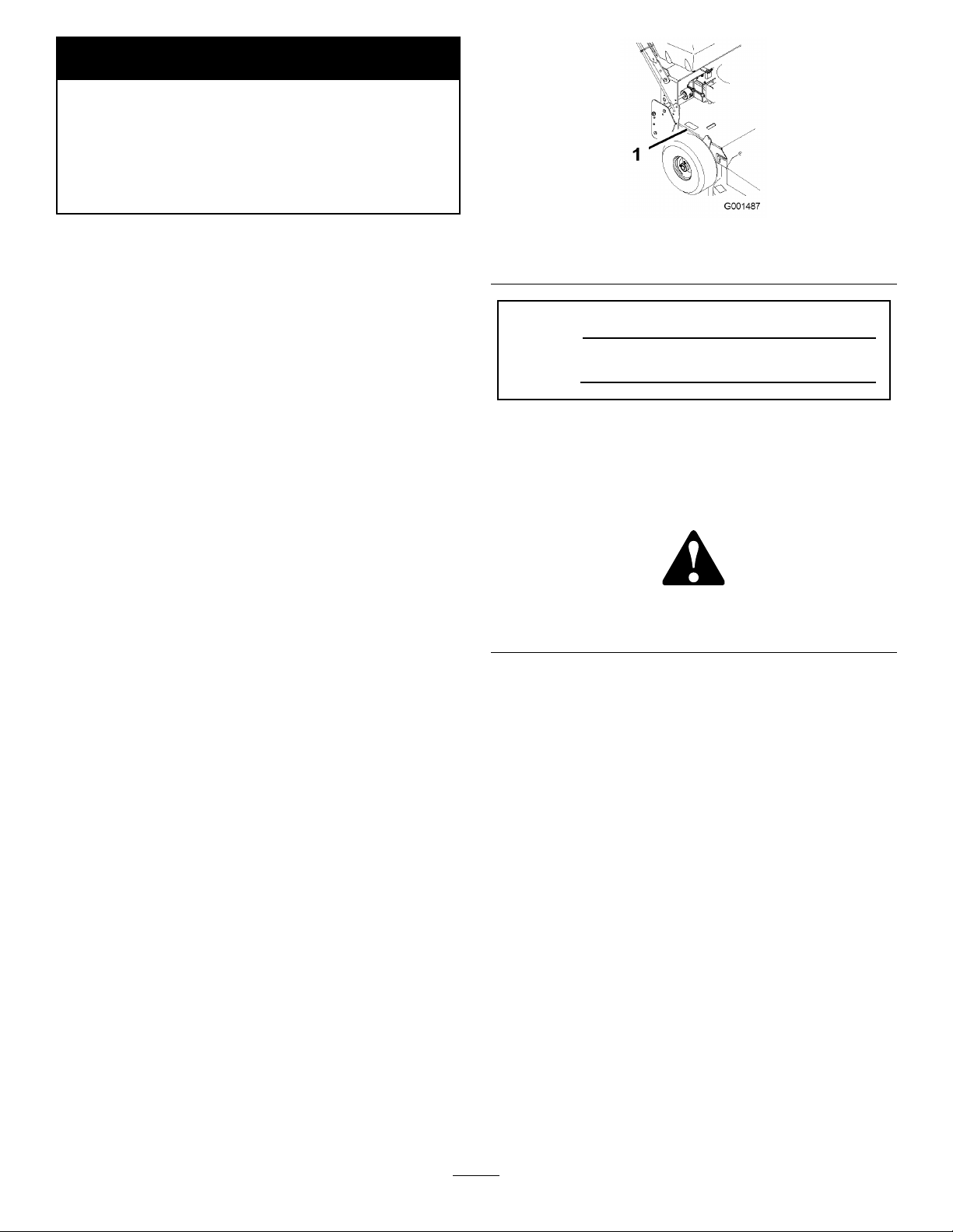
SlopeChart7SafetyandInstructional
Decals
Page 8

Safetydecalsandinstructionsareeasilyvisibletotheoperatorandarelocatednearanyareaof
potentialdanger.Replaceanydecalthatisdamagedorlost.
43-8480
95-5537
1.ReadtheOperator’s
Manualforinstructionson
operatingthecuttingblade
2.Pushforwardtoengage
3.Pullbacktodisengage
66-1340
98-0776
95-2814
99-3943
1.Engine
8
Page 9
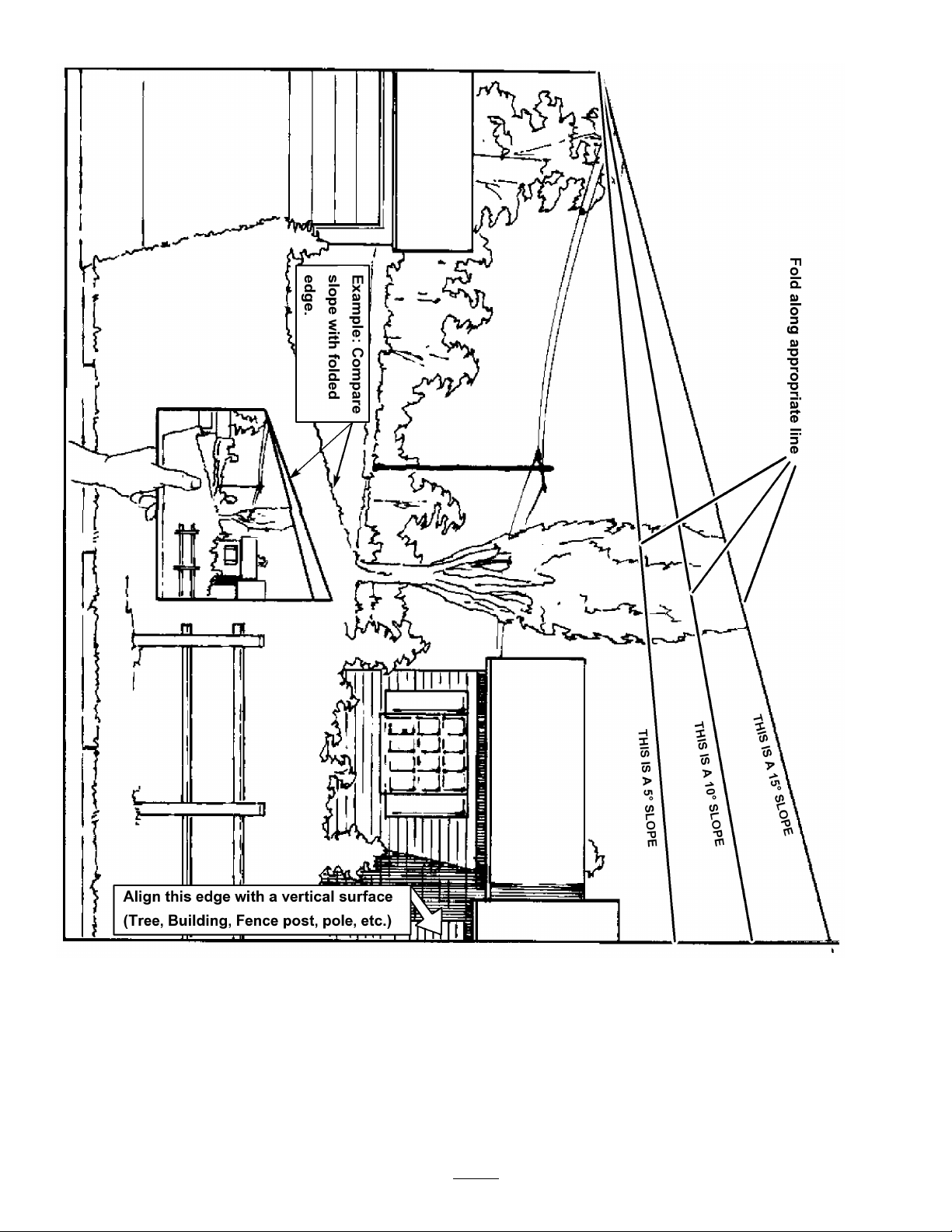
98-5130
1.Warning—readtheOperator’sManualforinstructionson
torquingthebladebolt/nutto75-80ft-lb(102-106N⋅m).
98-5954
104-8569
105-4104
1.Reverse3.Transmissionspeeds
2.Neutral
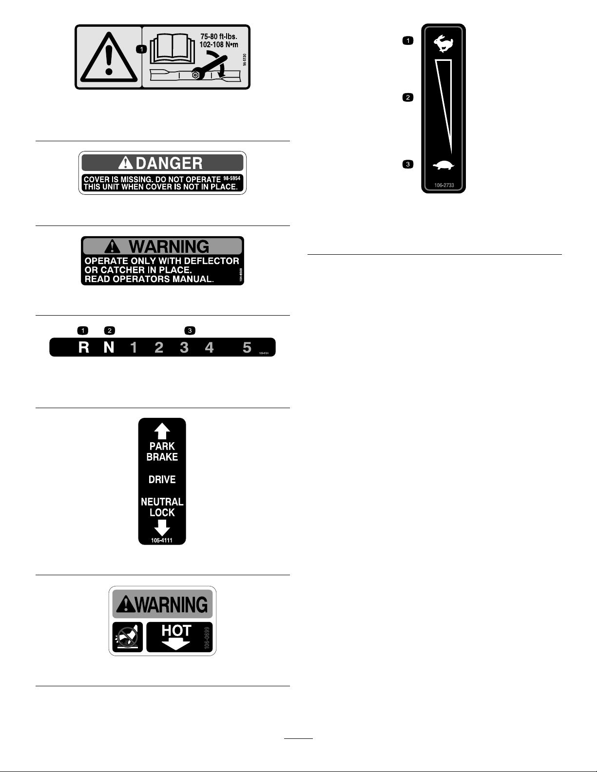
1.Fast
2.Continuousvariable
setting
106-2733
3.Slow
105-4111
106-0699
9
Page 10
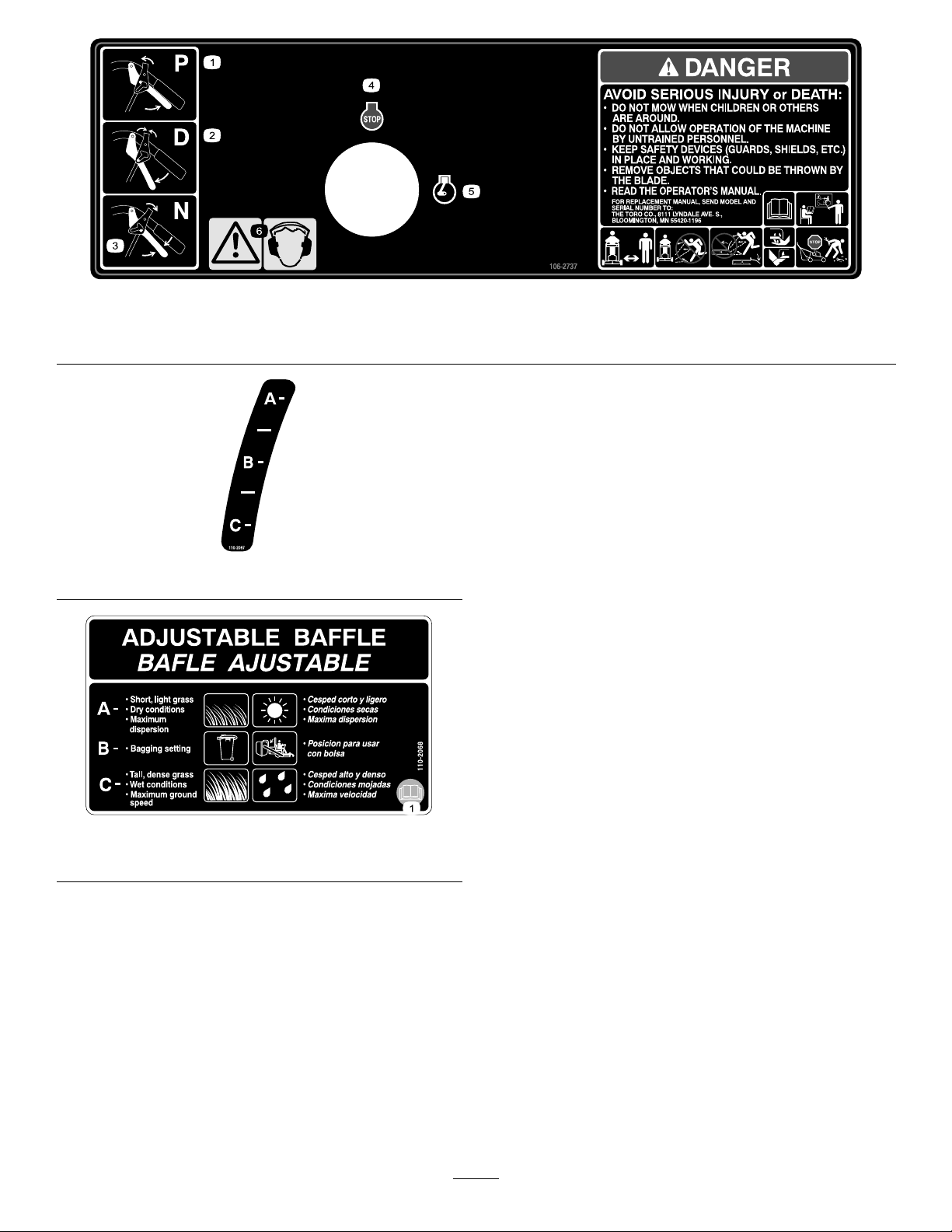
106-2737
1.Park3.Neutral5.Engine—run
2.Drive4.Engine—stop6.Warning—wearearprotection.
110-2067
110-2068
1.ReadtheOperator’sManual.
10
Page 11

Setup
LooseParts
Usethechartbelowtoverifythatallpartshavebeenshipped.
ProcedureDescription
1
2
Note:Determinetheleftandrightsidesofthemachinefromthenormaloperatingposition.
Nopartsrequired
Operator’sManual
EngineOperator’sManual
PartsCatalog
SafetyVideo
RegistrationCard
Oildrainhose
1
CheckingtheFluidsandTire
Pressure
NoPartsRequired
ReadingtheManualand
ViewingtheSafetyVideo
Partsneededforthisprocedure:
Qty.
–
1
1
1
1
1
1
2
Use
Checktheuidsandtirepressure.
ReadtheOperator’sManualandwatch
thevideobeforeoperatingthemachine.
Procedure
•Beforeyoustarttheengineandusethemachine,
checktheoillevelintheenginecrankcase;referto
CheckingtheEngineOilLevel.
•Checkthegreaseforthemowerandmowerdeck.
RefertotheLubricationSection.
•Checkthetirepressure;refertoCheckingtheTire
Pressure.
1
Operator’sManual
1
EngineOperator’sManual
1
PartsCatalog
1
SafetyVideo
1
RegistrationCard
1
Oildrainhose
Procedure
•ReadtheOperator’sManual.
•Viewthesafetyvideo.
•Fillouttheregistrationcardandmailitinorregister
onlineatwww .Toro.com.
•Usetheoildrainhosewhenchangingtheengineoil.
Note:Thecuttingbladesaresettoa3inch(76mm)
height-of-cutatinitialpurchase.TheaxlepositionisD,
with4spacersbelowboththespindleandthecaster.
11
Page 12
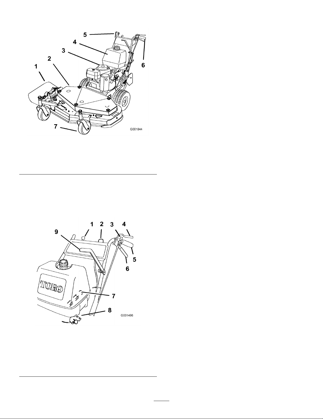
ProductOverview
1.Sidedischarge5.Controls
2.Mowerdeck6.Handle
3.Recoilstarter
4.Gastank
Figure3
ThrottleControl
Thethrottlecontrolhastwopositions:FastandSlow.
OperatorPresenceControl(OPC)
Levers
WhenyousqueezetheOPCleversagainstthehandles,
theOPCsystemsensesthattheoperatorisinthenormal
operatingposition.WhenyoureleasetheOPClevers,
theOPCsystemsensesthattheoperatorhasleftthe
normaloperatingposition,andthesystemwillstopthe
engineifeitherthegearshiftleverisnotintheneutral
positionorthebladecontrol(PTO)leverisengaged.
DriveLevers
Releasedriveleverstoengageforwardtraction
operation.Squeezerightsideofdrivelevertoturnright
andleftsidetoturnleft.
GearShiftLever
7.Casterwheel
Thetransmissionhasveforwardspeeds,neutraland
reverse,andhasanin-lineshiftpattern.
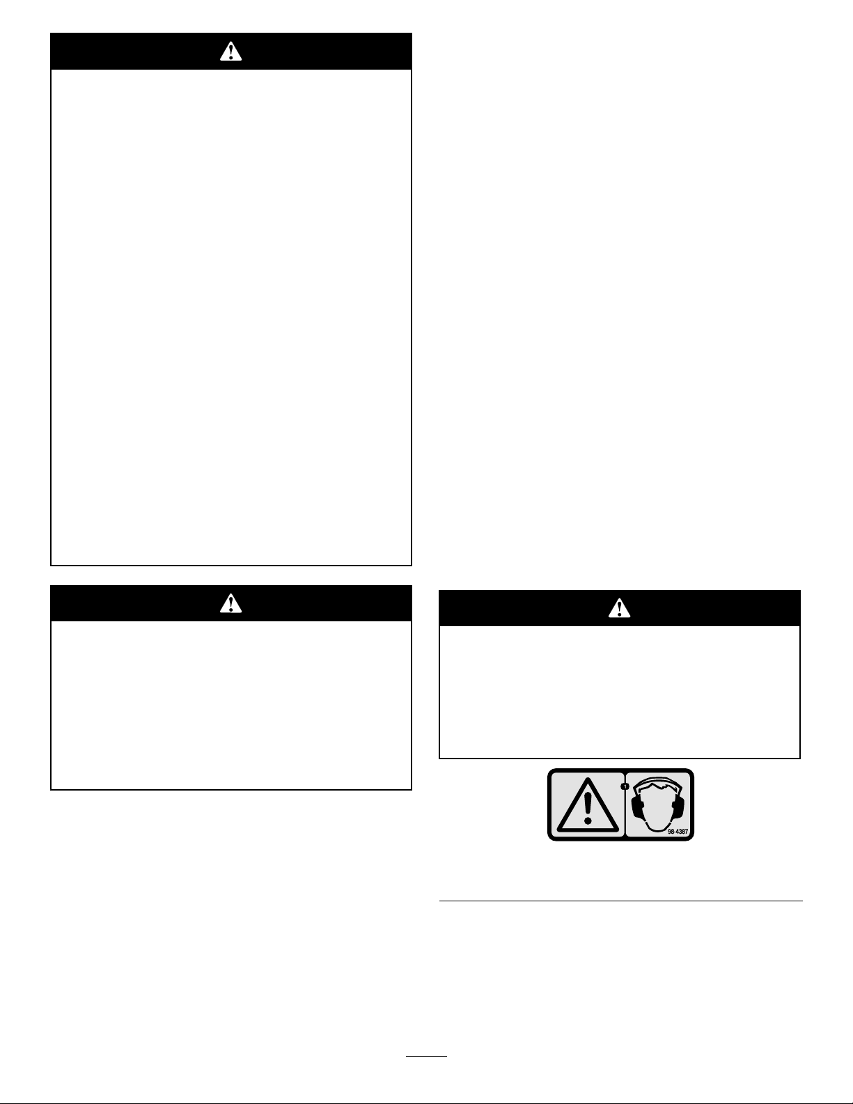
Controls
Becomefamiliarwithallthecontrols(Figure4)before
youstarttheengineandoperatethemachine.
Figure4
1.Throttlecontrol6.Drivelever
2.Ignitionswitch
3.Neutral/parkingbrakelock8.Choke
4.OperatorPresence
Control(OPC)lever
5.Handle
7.Gearshiftlever
9.Powertakeofflever(PTO)
Important:Donotshiftwhileunitismoving,as
transmissiondamagemayoccur.
Neutral/ParkingBrakeLock
Squeezedriveleversandmovethelocksrearwardfor
neutrallock.Squeezedriveleversandmovethelocks
forwardtosettheparkingbrake.
BladeControlLever(PTO)
ThisleverisusedinconjunctionwiththeOPClevers
toengageordisengagethemowerdeckbeltanddrive
themowerblades.
RecoilStarter
Pulltherecoilstarterhandletostartengine(notshown
in).
FuelShut-offValve
Closethefuelshut-offvalvewhentransportingor
storingmower.
IgnitionSwitch
Thisswitchisusedinconjunctionwithrecoilstarterand
hastwopositions:RunandOff.
Choke
Usethechoketostartacoldengine.
12
Page 13

Specications
Note:Specicationsanddesignaresubjecttochange
withoutnotice.
Operation
AddingFuel
40inchmowers:
Widthwithdeectordown55–1/2inches(141cm)
Length
Height
Weight
75–3/8inches(191.3cm)
41inches(104.1cm)
477lb(216kg)
48inchmowers:
Widthwithdeectordown63–1/2inches(161.3cm)
Length
Height
Weight
78–3/8inches(198.9cm)
41inches(104.1cm)
500lb(227kg)
Attachments/Accessories
AselectionofToroapprovedattachmentsand
accessoriesareavailableforusewiththemachineto
enhanceandexpanditscapabilities.Contactyour
AuthorizedServiceDealerorDistributororgoto
www.Toro.comforalistofallapprovedattachments
andaccessories.
UseUnleadedRegularGasolinesuitablefor
automotiveuse(85pumpoctaneminimum).Leaded
regulargasolinemaybeusedifunleadedregularisnot
available.
Important:Neverusemethanol,gasoline
containingmethanol,orgasoholcontainingmore
than10%ethanolbecausethefuelsystemcouldbe
damaged.Donotmixoilwithgasoline.
Incertainconditions,gasolineisextremely
ammableandhighlyexplosive.Areor
explosionfromgasolinecanburnyouand
othersandcandamageproperty.
•Fillthefueltankoutdoors,inanopenarea,
whentheengineiscold.Wipeupany
gasolinethatspills.
•Neverllthefueltankinsideanenclosed
trailer.
•Donotllthefueltankcompletelyfull.Add
gasolinetothefueltankuntilthelevelis1/4
to1/2inch(6to13mm)belowthebottomof
thellerneck.Thisemptyspaceinthetank
allowsgasolinetoexpand.
•Neversmokewhenhandlinggasoline,and
stayawayfromanopenameorwhere
gasolinefumesmaybeignitedbyaspark.
•Storegasolineinanapprovedcontainerand
keepitoutofthereachofchildren.Never
buymorethana30-daysupplyofgasoline.
•Donotoperatewithoutentireexhaust
systeminplaceandinproperworking
condition.
13
Page 14
Important:Donotusefueladditives
containingmethanolorethanol.
Incertainconditionsduringfueling,static
electricitycanbereleasedcausingaspark
whichcanignitethegasolinevapors.Are
orexplosionfromgasolinecanburnyouand
othersandcandamageproperty.
•Alwaysplacegasolinecontainersonthe
groundawayfromyourvehiclebeforelling.
•Donotllgasolinecontainersinsidea
vehicleoronatruckortrailerbedbecause
interiorcarpetsorplastictruckbedliners
mayinsulatethecontainerandslowtheloss
ofanystaticcharge.
•Whenpractical,removegas-powered
equipmentfromthetruckortrailerand
refueltheequipmentwithitswheelsonthe
ground.
•Ifthisisnotpossible,thenrefuelsuch
equipmentonatruckortrailerfroma
portablecontainer,ratherthanfroma
gasolinedispensernozzle.
•Ifagasolinedispensernozzlemustbeused,
keepthenozzleincontactwiththerimof
thefueltankorcontaineropeningatall
timesuntilfuelingiscomplete.
Addthecorrectamountofgas
stabilizer/conditionertothegas.
Note:Afuelstabilizer/conditionerismost
effectivewhenmixedwithfreshgasoline.To
minimizethechanceofvarnishdepositsinthefuel
system,usefuelstabilizeratalltimes.
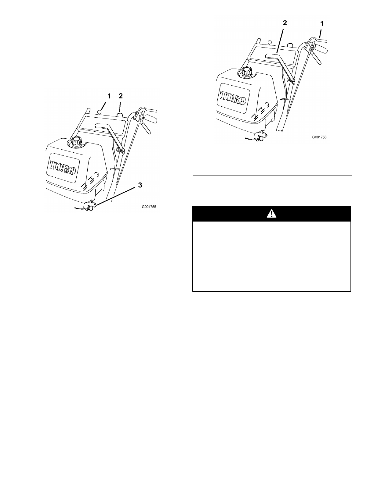
FillingtheFuelTank
1.Shuttheengineoffandsettheparkingbrake.
2.Cleanaroundfueltankcapandremovethecap.
Addunleadedregulargasolinetofueltank,untilthe
levelis1/4to1/2inch(6to13mm)belowthe
bottomofthellerneck.Thisspaceinthetank
allowsgasolinetoexpand.Donotllthefueltank
completelyfull.
3.Installfueltankcapsecurely.Wipeupanygasoline
thatmayhavespilled.
ThinkSafetyFirst
Carefullyreadallthesafetyinstructionsanddecalsin
thesafetysection.Knowingthisinformationcould
helpyouoranybystandersavoidinjury.
Theuseofprotectiveequipmentforeyes,hearing,feet
andheadisrecommended.
Gasolineisharmfulorfatalifswallowed.
Long-termexposuretovaporscancauseserious
injuryandillness.
•Avoidprolongedbreathingofvapors.
•Keepfaceawayfromnozzleandgastankor
conditionerbottleopening.
•Keepgasawayfromeyesandskin.
UsingStabilizer/Conditioner
Useafuelstabilizer/conditionerinthemachineto
providethefollowingbenets:
•Keepsgasolinefreshduringstorageof90daysor
less.Forlongerstorageitisrecommendedthatthe
fueltankbedrained.
•Cleanstheenginewhileitruns
•Eliminatesgum-likevarnishbuildupinthefuel
system,whichcauseshardstarting
Thismachineproducessoundlevelsinexcess
of85dBAattheoperator’searandcancause
hearinglossthroughextendedperiodsof
exposure.
Wearhearingprotectionwhenoperatingthis
machine.
Figure5
1.Warning—wearhearingprotection.
OperatingtheParkingBrake
andNeutralLocks
Alwayssettheparkingbrakeswhenyoustopthe
machineorleaveitunattended.
14
Page 15
Childrenorbystandersmaybeinjuredifthey
moveorattempttooperatethemachinewhile
itisunattended.
Alwayssettheparkingbrakewhenleaving
themachineunattended,evenifjustforafew
minutes.
ReleasingtheNeutralLocks
1.Squeezethedriveleversback.
2.Placeyourthumbsontheupperpartofthelocks
andmovethemforwarduntiltheyareinthedrive
position(Figure6).
StartingandStoppingthe
Engine
SettingtheParkingBrakes
1.Squeezethedrivelevers(Figure6).
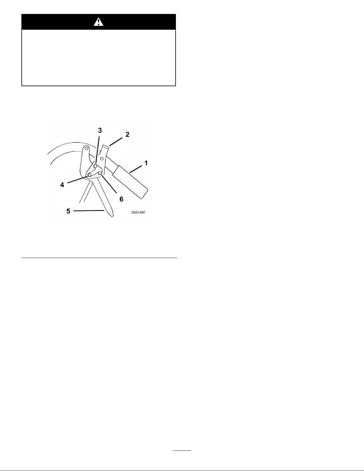
Figure6
1.Handle
2.Neutral/parkingbrakelock
3.Parkposition6.Neutralposition
2.Placeyourthumbsontheupperpartofthelocks
andmovethemforwardinintotheparkposition
(Figure6).
3.Releasethedrivelevers.
4.Fullspeedforward
5.Drivelever
ReleasingtheParkingBrakes
1.Squeezethedrivelevers(Figure6).
2.Placeyourthumbsontheupperpartofthelocks
andmovethemrearwarduntiltheyareinthedrive
position(Figure6).
StartingtheEngine
1.Connectthewirestothesparkplugs.
2.Openthefuelvalve.
3.Disengagethebladecontrol(PTO)leverandmove
theshiftlevertotheneutralposition.
4.Settheparkingbrakes.
5.Turntheignitionkeytotherunposition(Figure7).
6.Tostartacoldengine,movethethrottlecontrol
midwaybetweenthefastandslowpositions.
7.Tostartawarmengine,movethethrottlecontrol
tothefastposition.
8.Pullthechokeknobiftheengineiscold(Figure7).
Note:Awarmorhotengineusuallydoesnot
requireanychoking.
9.Grasptherecoilstarterhandlermlyandpullit
outuntilpositiveengagementresults;thenpullthe
handlevigorouslytostarttheengine.Allowthe
ropetorecoilslowly .
Important:Donotpulltherecoilropetoits
limitorreleasethestarterhandlewhenyoupull
outtheropebecausetheropemaybreakorthe
recoilassemblymaybedamaged.
10.Pushthechoketooffastheenginewarmsup.
11.Iftheengineiscold,allowittowarmupandthen
movethethrottlecontroltothefastposition.
StoppingtheEngine
SettingtheNeutralLocks
1.Squeezethedrivelevers(Figure6).
2.Placeyourthumbsontheupperpartofthelocks
andmovethemrearwardintotheneutrallock
position(Figure6).
Important:Inanemergency ,youcanstopthe
engineimmediatelybyturningtheignitionkeyto
the
of f
position.
1.Movethethrottlelevertotheslowposition.
2.Letengineidlefor30to60secondsbeforeturning
theignitionkeytooff.
3.Turntheignitionkeytotheoffposition.
4.Settheparkingbrakesandremovethekey .
15
Page 16
5.Disconnectthewirefromthesparkplugtoprevent
someonefromaccidentallystartingthemachine
whiletransportingorperformingmaintenanceonit.
6.Closethefuelshut-offvalvebeforetransporting
orstoringthemachine.
Important:Closethefuelshut-offvalvebefore
transportingorthestoringthemachineto
preventfuelleakage.
1.OperatorPresence
Control(OPC)lever
TheSafetyInterlockSystem
Figure8
2.Bladecontrollever(PTO)
Figure7
1.Throttlecontrol
2.Ignitionswitch
3.Choke
OperatingtheBladeControl
(PTO)Lever
Thebladecontrol(PTO)leverengagesanddisengages
thepowertothemowerblades.
EngagingtheMowerBlades(PTO)
1.Squeezetheoperatorpresencecontrol(OPC)levers
againstthehandles(Figure8).
2.Pushthebladecontrol(PTO)leverrmlyforward
untilitlatchesoverthecenter(Figure8).
3.Restarttheengineandrepeattheprocedureto
engagethemowerbladesiftheoperatorpresence
control(OPC)leversarereleased.
DisengagingtheMowerBlades(PTO)
Todisengagetheblades,pullthebladecontrollever
rearwardalltheway(Figure8).Theenginewillkill
whentheOPCleversarereleasedwiththebladecontrol
leverengaged.
Ifsafetyinterlockswitchesaredisconnected
ordamagedthemachinecouldoperate
unexpectedlycausingpersonalinjury.
•Donottamperwiththeinterlockswitches.
•Checktheoperationoftheinterlock
switchesdailyandreplaceanydamaged
switchesbeforeoperatingthemachine.
UnderstandingtheSafetyInterlock
System
Thesafetyinterlocksystemisdesignedtopreventthe
enginefromstartingunless:
•Thebladecontrol(PTO)leverisdisengaged.
•ThemachineisshiftedintotheNeutralposition.
•TheignitionkeyisintheRunposition.
Thesafetyinterlocksystemisalsodesignedtostopthe
enginewhen:
•TheignitionkeyisturnedtotheOffposition.
•Themachineisshiftedintogearwithoutholding
theOPClevers.
Note:Itisnecessarytofullyandmanuallydisengage
thebladecontrollever.
•Thebladecontrol(PTO)leverisengagedwithout
holdingtheOPClevers.
16
Page 17

TestingtheSafetyInterlockSystem
ServiceInterval:Beforeeachuseordaily
Testthesafetyinterlocksystembeforeyouusethe
machineeachtime.Ifthesafetysystemdoesnot
operateasdescribed,haveanAuthorizedService
Dealerrepairthesafetysystemimmediately .
1.Settheparkingbrakes,movetheshiftleverintothe
Neutralposition,disengagethebladecontrol(PTO)
leverandplacethethrottleforward.
2.Starttheengine;refertoStartingtheEngine.
3.WithoutholdingtheOperatorPresenceControl
(OPC)levers,engagethebladecontrol(PTO)lever.
Theengineshouldstop.
4.Disengagethebladecontrol(PTO)lever.
5.Withtheenginerunning,holddowntheOPC
leversandengagethebladecontrol(PTO)lever.
Thedrivebeltshouldengageandthemowerblades
beginrotating.
6.ReleasetheOPClevers.Theengineshouldstop.
7.Withtheenginerunning,movetheshiftleverinto
gearandreleasetheOPClevers.Theengineshould
stop.
8.Withtheenginerunning,turntheignitionkeyto
theoffposition.Theengineshouldstop.
9.Ifalltheaboveconditionsarenotmet,havean
AuthorizedServiceDealerrepairthesafetysystem
immediately.
2.SqueezetheOPCleversagainstthehandles.
3.Movetheshiftleverintothereversegear.
4.Releasetheparkingbrakes;refertoReleasingthe
ParkingBrakesandNeutralLocks.
5.Slowlyreleasethedrivelevers.
Note:Youmustpullthemowerbackwardtoassist
itsrearwardmovement.
StoppingtheMower
1.Squeezethedriveleversallthewaybacktoengage
thebrakes.
2.Settheparkingbrakes.RefertoSettingtheParking
Brakes.
3.ShifttransmissionintotheNeutralposition.
4.MovethethrottletotheStopposition,andwaitfor
allmovingpartstostopbeforeleavingtheoperating
position.
Childrenorbystandersmaybeinjuredifthey
moveorattempttooperatethemachinewhile
itisunattended.
Alwaysremovetheignitionkeyandsetthe
parkingbrakewhenleavingthemachine
unattended,evenifjustforafewminutes.
DrivingForwardorBackward
Thethrottlecontrolregulatestheenginespeedas
measuredinRPM(revolutionsperminute).Placethe
throttlecontrolinthefastpositionforbestmowing
performance.
DrivingForward
1.Ensurethattheparkingbrakesareengaged.
2.Movetheshiftleverintoaforwardgear.
3.SqueezetheOPCleversagainstthehandles.
4.Releasetheparkingbrakes;refertoReleasingthe
ParkingBrakesandNeutralLocks.
5.Slowlyreleasethedrivelevers.
Note:Togostraight,releasethedrivelevers
equally.Toturn,squeezethedriveleveronthesame
sideasthedirectionyouwanttoturn.
DrivingBackward
1.Ensurethattheparkingbrakesareengaged.
TransportingMachines
Useaheavy-dutytrailerortrucktotransportthe
machine.Ensurethatthetrailerortruckhasall
necessarylightingandmarkingasrequiredbylaw .
Pleasecarefullyreadallthesafetyinstructions.
Knowingthisinformationcouldhelpyou,yourfamily ,
petsorbystandersavoidinjury.
Totransportthemachine:
•Stoptheengine,removethekey ,setthebrake,and
closethefuelvalve.
•Securelyfastenthemachinetothetrailerortruck
withstraps,chains,cable,orropes.
•Secureatrailertothetowingvehiclewithsafety
chains.
SideDischargingorMulching
theGrass
Thismowerhasahingedgrassdeectorthatdisperses
clippingstothesideanddowntowardtheturf.
17
Page 18

Withoutthegrassdeector,dischargecover,
orcompletegrasscatcherassemblymounted
inplace,youandothersareexposedtoblade
contactandthrowndebris.Contactwith
rotatingmowerblade(s)andthrowndebriswill
causeinjuryordeath.
•Neverremovethegrassdeectorfrom
themowerbecausethegrassdeector
routesmaterialdowntowardtheturf.Ifthe
grassdeectoriseverdamaged,replaceit
immediately.
•Neverputyourhandsorfeetunderthe
mower.
•Nevertrytocleardischargeareaormower
bladesunlessyoureleasethebailandthe
powertakeoff(PTO)isoff.Rotatethe
ignitionkeytoOff.Alsoremovethekeyand
pullthewireoffthesparkplug(s).
Figure9
1.PositionA4.Drivespring
2.PositionB
3.PositionC
5.Adjustmentbolt(In
positionA)
6.Drivepulleyshield
5.Removethelocknutthatsecurestheadjustment
bolttothedrivepulleyshield(Figure9).
6.Locateboltassemblyinthedesiredtensionposition
asfollows:
AdjustingtheWheelDrive
Tension
Youmayneedtoincreasethewheeldrivebelttension
undercertainoperatingconditions,suchasmowerover
hillyterrainorwhilepullingasulky.
1.Stoptheengine,removethekey ,andwaitforall
movingpartstostop.
2.Disconnectthewiresfromthesparkplugs.
3.Disengagetheneutral/parkingbrakelocks,and
releasethedriveleverstoreducethespringforce.
4.Removethedrivespringfromtheadjustmentbolt
(Figure9).
•PositionAfornormalconditions
•PositionBformoresevereconditions
•PositionCforthemostsevereconditions
Note:Thewheeldrivetensionislowestwhen
theboltassemblyisinPositionA.Thetension
increasesinPositionsBandC(Figure9).
7.Installtheadjustmentboltandthedrivespring.
8.Repeatstepsthroughfortheoppositeside.
AdjustingtheHeight-of-Cut
Thismachinehasa1to4-1/4inch(26to108mm)
rangefortheheight-of-cut.Thiscanbeachievedby
adjustingbladespacers,rearaxleheight,andfront
casterspacers.UsetheHeight-of-CutCharttoselect
thecombinationofadjustmentsrequired.
AdjustingtheBladeHeight
Adjustthebladesbyusingthe4spacers(1/4inch)
(6mm)onthebladespindlebolts.Thisallowsfora
1-inch(25mm)adjustmentrange,in1/4inch(6mm)
increments,ofcuttingheightinanyaxleposition.Use
thesamenumberofbladespacersonallbladesto
achievealevelcut(2aboveand2below,1aboveand3
below,etc.).
1.Disengagethebladecontrol(PTO)leverandset
theparkingbrakes.
18
Page 19

2.Stoptheengineandwaitforallmovingpartsto
stopbeforeleavingtheoperatingposition.
3.Holdthebladeboltandremovethenut(Figure10).
Figure11
1.Axlepivotbolt2.Axleadjustmentbolt
4.Placeajackundertherearcenteroftheengine
frame.Raisethebackendoftheengineframeup
enoughtoremovethefront2axleadjustmentbolts
(Figure11).
Note:Usejackstandstosupportthemachine.
5.Raiseorlowertheengineframewiththejackso
thatyoucaninstallthefront2axleadjustmentbolts
inthedesiredholelocation(Figure11).
Figure10
1.Blade
2.Bladebolt5.Thinwasher
3.Curvedwasher
4.Spacer
6.Nut
4.Slidetheboltdownthroughthespindle,andchange
thespacersasneeded(Figure10).
5.Installtheboltandcurvedwasher,addextra
spacer(s),andsecurethemwithathinwasheranda
nut(Figure10).
6.Torquethebladeboltto75-80ft-lb(101-108N•m).
AdjustingtheAxleHeight
Adjusttheaxlepositiontotheselectedheight-of-cut
setting.RefertotheHeight-of-CutChart.
Note:Useataperedpunchtohelpaligntheholes.
6.Tightenall4boltsandlowerthemower.
7.Adjustthecontrolrodsandthebrakelinkages
asrequired.RefertoServicingtheBrakesand
AdjustingtheControlRods.
Important:Youmustadjustthecontrolrods
andthebrakelinkagewhenyouchangethe
axlepositionsforpropertractionandbrake
function.
AdjustingtheCasterPosition
1.UsingtheHeight-of-CutChart,adjustthecaster
spacerstomatchwiththeaxleholeselected
(Figure12).
1.Disengagethebladecontrol(PTO)leverandset
theparkingbrakes.
2.Stoptheengineandwaitforallmovingpartsto
stopbeforeleavingtheoperatingposition.
3.Loosen,butdonotremove,the2axlepivotbolts
andthe2axleadjustmentbolts(Figure11).
19
Page 20

Figure12
1.Latchpin
2.Spacer,3/16inch(5mm)
3.Spacer,1/2inch(13mm)
2.Removethelatchpin,slidethecasterfromthe
support,andchangethespacers(Figure12).
1.Camlock
2.Lever
Figure13
3.Rotatecamtoincreaseor
decreaselockingpressure
4.Slot
3.Installthecasterinthesupportandinsertthelatch
pin(Figure12).
AdjustingtheFlowBafe
Themowerdischargeowcanbeadjustedfordifferent
typesofmowingconditions.Positionthecamlockand
bafetogivethebestqualityofcut.
1.DisengagethePTO,movethemotioncontrol
leverstotheneutrallockedpositionandsetthe
parkingbrake.
2.Stoptheengine,removethekey ,andwaitforall
movingpartstostopbeforeleavingtheoperating
position.
3.Toadjustthecamlock,swingtheleveruptoloosen
thecamlock(Figure13).
4.Adjustthebafeandcamlockintheslottothe
desireddischargeow .
5.Swingtheleverbackovertotightenthebafeand
camlock(Figure13).
PositioningtheFlowBafe
Thefollowingguresareonlyrecommendationsfor
use.Adjustmentswillvarybygrasstype,moisture
content,andheightofgrass.
Note:Iftheenginepowerdrawsdownandthemower
groundspeedisthesame,openupthebafe.
6.Ifthecamdoesnotlockthebafeintoplaceoritis
tootight,loosentheleverandthenrotatethecam
lock.Adjustthecamlockuntilthedesiredlocking
pressureisachieved.
20
Page 21

PositionA
Thisisthefullrearposition.Thesuggesteduseforthis
positionisafollows(Figure14).
•Useforshort,lightgrassmowingconditions.
•Useindryconditions.
•Forsmallergrassclippings.
•Propelsgrassclippingsfartherawayfromthe
mower.
Figure14
PositionB
Usethispositionwhenbagging(Figure15).
Figure15
PositionC
Thisisthefullopenposition.Thesuggestedusefor
thispositionisasfollows(Figure16).
•Useintall,densegrassmowingconditions.
•Useinwetconditions.
•Lowerstheenginepowerconsumption.
•Allowsincreasedgroundspeedinheavyconditions.
•ThispositionissimilartothebenetsoftheToro
SFSmower.
21
Page 22

Figure16
AdjustingtheHandleHeight
Thehandlepositioncanbeadjustedtomatchthe
operator’sheightpreference.
1.Removethehairpincotterpinsandclevispinsfrom
thedriveleversandneutrallocks(Figure17).
Figure17
1.Controlrod
2.Clevispin
3.OperatorPresence
Controllever(OPC)
4.Handle8.Drivelever
5.Neutrallock
6.Hairpincotterpin
7.Lefthandleshown
2.Loosentheupperbolts(3/8x1-1/4inch)and
angenutsecuringhandletorearframe(Figure18).
3.Removethelowerbolts(3/8x1inch)andange
nutssecuringhandletorearframe(Figure18).
4.Pivothandletodesiredoperatingpositionand
installlowerangebolts(3/8x1inch)andange
nutsintomountingholes.Tightenallangebolts.
Figure18
1.Upperhandle6.Lowermountingholes
2.Rearframe
3.Flangebolt(3/8x1inch)
4.Locknut(3/8inch)
5.Uppermountinghole
22
7.Lowposition
8.Middleposition
9.Highposition
Page 23

5.Adjustthecontrolrodlengthbyrotatingthecontrol
rodintherodtting(Fig.8).
6.Installhairpincotterbetweendriveleversand
neutrallocksandintoclevispins(Fig.25).
Note:Makesuretheclevispinsareinsertedinto
theneutrallocks.
7.Checktheparkingbrakeadjustment.Referto
CheckingtheBrakesinBrakeMaintenance,
page35.
23
Page 24

HeightofCutChart
Numberofspacers
1/2inch
AxlePosition
A00
A01
A10
B01
B10
B11
B20
C
C
C
C
D21
D30
D31
D40
E31
E40
E41
(13mm)
11
20
21
30
belowcaster
3/16inch(5
mm)
1inch(26
1–1/8inch
(29mm)
1–3/8inch
(35mm)
1–3/8inch
(35mm)
1–5/8inch
(41mm)
1–3/4inch
(45mm)
2inch(51
1–7/8inch
(48mm)
2–1/8inch
(55mm)
2–1/4inch
(57mm)
2–1/2inch
(64mm)
2–3/8inch
(61mm)
2–1/2inch
(64mm)
2–3/4inch
(70mm)
3inch(76
2–7/8inch
(73mm)
3–1/8inch
(79mm)
3–1/4inch
(82mm)
Numberof1/4inchbladespacersbelowspindle
43210
mm)
mm)
mm)
1–1/4inch
(32mm)
1–3/8inch
(35mm)
1–5/8inch
(41mm)
1–5/8inch
(41mm)
1–7/8inch
(48mm)
2inch(51
mm)
2–1/4inch
(57mm)
2–1/8inch
(54mm)
2–3/8inch
(60mm)
2–1/2inch
(64mm)
2–3/4inch
(70mm)
2–5/8inch
(67mm)
2–3/4inch
(70mm)
3inch(76
mm)
3–1/4inch
(82mm)
3–1/8inch
(79mm)
3–3/8inch
(86mm)
3–1/2inch
(89mm)
1–1/2inch
(38mm)
1–5/8inch
(41mm)
1–7/8inch
(48mm)
1–7/8inch
(48mm)
2–1/8inch
(54mm)
2–1/4inch
(57mm)
2–1/2inch
(64mm)
2–3/8inch
(60mm)
2–5/8inch
(67mm)
2–3/4inch
(70mm)
3inch(76
2–7/8inch
(73mm)
3inch(76
3–1/4inch
(82mm)
3–1/2inch
(89mm)
3–3/8inch
(86mm)
3–5/8inch
(92mm)
3–3/4inch
(95mm)
1–3/4inch
(45mm)
1–7/8inch
(48mm)
2–1/8inch
(54mm)
2–1/8inch
(54mm)
2–3/8inch
(60mm)
2–1/2inch
(64mm)
2–3/4inch
(70mm)
2–5/8inch
(67mm)
2–7/8inch
(73mm)
3inch(76
mm)
mm)
mm)
3–1/4inch
(83mm)
3–1/8inch
(79mm)
3–1/4inch
(82mm)
3–1/2inch
(89mm)
3–3/4inch
(95mm)
3–5/8inch
(92mm)
3–7/8inch
(98mm)
4inch(102
mm)
2inch(51
mm)
2–1/8inch
(54mm)
2–3/8inch
(60mm)
2–3/8inch
(60mm)
2–5/8inch
(67mm)
2–3/4inch
(70mm)
3inch(76
mm)
2–7/8inch
(73mm)
3–1/8inch
(79mm)
3–1/4inch
(83mm)
3–1/2inch
(89mm)
3–3/8inch
(86mm)
3–1/2inch
(89mm)
3–3/4inch
(95mm)
4inch(102
mm)
3–7/8inch
(98mm)
4–1/8inch
(105mm)
4–1/4inch
(108mm)
24
Page 25

Maintenance
Note:Determinetheleftandrightsidesofthemachinefromthenormaloperatingposition.
RecommendedMaintenanceSchedule(s)
MaintenanceService
Interval
Aftertherst8hours
Aftertherst25hours
Beforeeachuseordaily
Every25hours
Every50hours
Every100hours
Every200hours
MaintenanceProcedure
•Changetheengineoil.
•Checkthemowerbelttension.
•Checkthemowerbelttension.
•Checkthesafetysystem.
•Greasethecasterwheelsandcasterpivot.
•Checktheengineoillevel.
•Cleantheairintakescreen.
•Checkthebrakes.
•Inspecttheblades.
•Cleanthemowerdeck.
•Cleanfoamaircleanerelement.
•Greasethemowerbeltidler .
•Checkthepaperaircleanerelement.
•Checkthetirepressure.
•Checkthebelts.
•Checkthemowerbelttension.
•Changetheengineoil.
•Checkthesparkplugs.
•Checkandcleanenginecoolingnsandshrouds.
•Replacethepaperaircleanerelement.
•Replacetheoillter.
•Replacethefuellter.
Every250hours
Every400hours
Beforestorage
•Greasethetransmissioncouplers(moreoftenindirtyordustyconditions).
•Greasethewheelbearings(moreoftenindirtyordustyconditions).
•LubricatecamlockwithNever-Seez®.
•Paintchippedsurfaces.
•Performallmaintenanceprocedureslistedabovebeforestorage.
Important:Refertoyourengineoperator’smanualforadditionalmaintenanceprocedures.
Ifyouleavethekeyintheignitionswitch,someonecouldaccidentlystarttheengineandseriously
injureyouorotherbystanders.
Removethekeyfromtheignitionanddisconnectthesparkplugwirefromthesparkplug(s)beforeyou
doanymaintenance.Setthewireasidesothatitdoesnotaccidentallycontactthesparkplug.
Lubrication
GreasewithNo.2generalpurposelithiumbaseor
HowtoGrease
1.DisengagethePTOandsettheparkingbrake.
molybdenumbasegrease.
25
Page 26

2.Stoptheengine,removethekey,andwaitforall
movingpartstostopbeforeleavingtheoperating
position.
3.Cleanthegreasettingswitharag.Makesureto
scrapeanypaintoffthefrontofthetting(s).
4.Connectagreaseguntothetting.Pumpgrease
intothettingsuntilgreasebeginstooozeoutof
thebearings.
5.Wipeupanyexcessgrease.
LubricatingtheCasterand
WheelBearings
ServiceInterval:Beforeeachuseordaily
Every400hours
Figure20
GreasingtheMowerBeltIdler
ServiceInterval:Every50hours
Every400hours
1.Lubricatethefrontwheelbearingsandfrontspindles
Figure19).
(
2.Lubricatethedrivewheelbearings.
Figure19
GreasingtheTransmission
Greasethettingonthemowerbeltidlerarmpivot
(Figure21).
Note:Removethemowerdeckcovertoaccessthe
greasettingforthemowerbeltidlerarm.
Figure21
Couplers
ServiceInterval:Every250hours
Lubricatethetransmissioncouplerslocatedintheback
ofthemachine(Figure20).
26
Page 27

EngineMaintenance
ServicingtheAirCleaner
ServiceInterval/Specication
Foamelement:Cleanitafterevery25operatinghours.
Paperelement:Checkitafterevery50operatinghours.
Replaceitafterevery200operatinghoursoryearly,
whichevercomesrst.
Inspectthefoamandpaperelementsandreplacethem
iftheyaredamagedorexcessivelydirty.
Note:Servicetheaircleanermorefrequently(every
fewoperatinghours)iftheoperatingconditionsare
extremelydustyorsandy .
Important:Donotoilthefoamorpaperelement.
RemovingtheFoamandPaper
Elements
1.DisengagethePTOandsettheparkingbrake.
2.Stoptheengine,removethekey,andwaitforall
movingpartstostopbeforeleavingtheoperating
position.
3.Cleanaroundtheaircleanertopreventdirt
fromgettingintotheengineandcausingdamage
(Figure22).
4.Unscrewthecoverknobandremovetheaircleaner
cover(Figure22).
5.Removethe2wingnutsandremovetheaircleaner
assembly(Figure22).
6.Carefullypullthefoamelementoffthepaper
element(Figure22).
Figure22
1.Engine4.Foamelement
2.Cover
3.Wingnut
5.Paperelement
6.Coverknob
CleaningtheFoamAirCleanerElement
ServiceInterval:Every25hours
1.Washthefoamelementinliquidsoapandwarm
water.Whentheelementisclean,rinseitthoroughly.
2.Drytheelementbysqueezingitinacleancloth.
Important:Replacethefoamelementifitis
tornorworn.
ServicingthePaperAirCleaner
Element
ServiceInterval:Every50hours
Every200hours
1.Donotcleanthepaperlter.Replaceitafter200
operatinghours(Figure22).
2.Inspecttheelementfortears,anoilylm,ordamage
totherubberseal.
3.Replacethepaperelementifitisdamaged.
27
Page 28

InstallingtheFoamandPaperElements
Important:Topreventenginedamage,always
operatetheenginewiththecompletefoamand
paperaircleanerassemblyinstalled.
1.Carefullyslidethefoamelementontothepaperair
cleanerelement(Figure22).
2.Placetheaircleanerassemblyontotheaircleaner
baseandsecureitwiththe2wingnuts(Figure22).
3.Placetheaircleanercoverintopositionandtighten
thecoverknob(Figure22).
4.Cleanaroundtheoildipstick(Figure24)sothatdirt
cannotfallintothellerholeanddamagetheengine.
ServicingtheEngineOil
ServiceInterval/Specication
Changetheengineoilasfollows:
•Aftertherst8operatinghours
•Afterevery100operatinghours
Note:Changetheoilmorefrequentlywhenthe
operatingconditionsareextremelydustyorsandy.
OilType:Detergentoil(APIserviceSF ,SG,SH,
orSJ)
CrankcaseCapacity:58ounces(1.7liter)withthe
lterremoved;51ounces(1.5liter)withoutthelter
removed
Viscosity:Refertothefollowingtable(Figure23).
Figure24
1.Oildipstick
5.Unscrewtheoildipstickandwipetheendclean
(Figure24).
6.Slidetheoildipstickfullyintothellertube,butdo
notthreadontotube(Figure24).
7.Pullthedipstickoutandlookattheend.Iftheoil
levelislow,slowlypouronlyenoughoilintotheller
tubetoraisetheleveltotheFullmark.
Important:Donotoverllthecrankcasewith
oilandruntheengine;enginedamagecan
result.
2.Fillertube
ChangingtheOil
ServiceInterval:Aftertherst8hours
Every100hours
1.Starttheengineandletitrunveminutes.This
warmstheoilsoitdrainsbetter.
Figure23
CheckingtheEngineOilLevel
ServiceInterval:Beforeeachuseordaily
1.Parkthemachineonalevelsurface.
2.DisengagethePTO,turntheignitionkeytooff,and
removethekey.
3.Waitforallmovingpartstostopbeforeleavingthe
operatingpositionandthensettheparkingbrake.
2.Parkthemachinesothatthedrainsideisslightly
lowerthantheoppositesidetoassuretheoildrains
completely.
3.DisengagethePTOandsettheparkingbrake.
4.Stoptheengine,removethekey,andwaitforall
movingpartstostopbeforeleavingtheoperating
position.
5.Slidethedrainhoseovertheoildrainvalve.
6.Placeapanbelowthedrainhose.Rotateoildrain
valvetoallowoiltodrain(Figure25).
7.Whenoilhasdrainedcompletely,closethedrain
valve.
8.Removethedrainhose(Figure25).
Note:Disposeoftheusedoilatarecyclingcenter.
28
Page 29

Figure25
1.Oildrainvalve2.Oildrainhose
Figure26
1.Oillter
2.Adapter
3.Applyathincoatofnewoiltotherubbergasketon
thereplacementlter(Figure26).
4.Installthereplacementoilltertothelteradapter,
turntheoillterclockwiseuntiltherubbergasket
contactsthelteradapter,thentightenthelteran
additional3/4turn(Figure26).
9.Slowlypourapproximately80%ofthespeciedoil
intothellertube(Figure24).
10.Checktheoillevel;refertoCheckingtheEngineOil
Level.
11.SlowlyaddtheadditionaloiltobringittotheFull
mark.
ChangingtheOilFilter
ServiceInterval:Every200hours
Replacetheoillterevery200operatinghoursorevery
otheroilchange.
Note:Changetheoilltermorefrequentlywhenthe
operatingconditionsareextremelydustyorsandy .
1.Draintheoilfromtheengine;refertoChangingthe
EngineOil.
2.Removetheoldlter(Figure26).
5.Fillthecrankcasewiththepropertypeofnewoil;
refertoServicingtheEngineOil.
6.Runtheengineforabout3minutes,stoptheengine,
andcheckforoilleaksaroundtheoillteranddrain
valve.
7.Checktheengineoillevelandaddoilifneeded.
ServicingtheSparkPlugs
ServiceInterval/Specication
Checkthesparkplugsafterevery100operatinghours.
Ensurethattheairgapbetweenthecenterandside
electrodesiscorrectbeforeinstallingthesparkplug.
Useasparkplugwrenchforremovingandinstallingthe
sparkplugsandagappingtool/feelergaugetocheckand
adjusttheairgap.Installanewsparkplugsifnecessary.
Type:Champion®RCJ8YorequivalentAirGap:
0.030inch(0.75mm)
RemovingtheSparkPlugs
1.DisengagethePTOandsettheparkingbrake.
2.Stoptheengine,removethekey,andwaitforall
movingpartstostopbeforeleavingtheoperating
position.
3.Disconnectthewiresfromthesparkplugs
(Figure27).
29
Page 30

Figure27
1.Spark-plugwire/sparkplug
4.Cleanaroundthesparkplugstopreventdirtfrom
fallingintotheengineandpotentiallycausing
damage.
Important:Alwaysreplacethesparkplugs
whenithasablackcoating,wornelectrodes,
anoilylm,orcracks.
3.Checkthegapbetweenthecenterandsideelectrodes
(Figure28).Bendthesideelectrode(Figure28)if
thegapisnotcorrect.
InstallingtheSparkPlugs
1.Installthesparkplugsandthemetalwasher.Ensure
thattheairgapissetcorrectly.
2.Tightenthesparkplugsto16ft-lb(22N•m).
3.Connectthewirestothesparkplugs(Figure28).
5.Removethesparkplugsandthemetalwashers.
CheckingtheSparkPlugs
ServiceInterval:Every100hours
1.Lookatthecenterofthesparkplugs(Figure28).
Ifyouseelightbrownorgrayontheinsulator,the
engineisoperatingproperly .Ablackcoatingonthe
insulatorusuallymeansthattheaircleanerisdirty.
2.Ifneeded,cleanthesparkplugwithawirebrushto
removecarbondeposits.
Figure28
1.Centerelectrodeinsulator3.Airgap(nottoscale)
2.Sideelectrode
30
Page 31

FuelSystem
Maintenance
ServicingtheFuelTank
Incertainconditions,gasolineisextremely
ammableandhighlyexplosive.Areor
explosionfromgasolinecanburnyouand
othersandcandamageproperty.
•Draingasolinefromthefueltankwhenthe
engineiscold.Dothisoutdoorsinanopen
area.Wipeupanygasolinethatspills.
Figure29
1.Fuelshut-offvalve2.Clamp
•Neversmokewhendraininggasoline,and
stayawayfromanopenameorwherea
sparkmayignitethegasolinefumes.
DrainingtheFuelTank
1.Parkthemachineonalevelsurface,toassurefuel
tankdrainscompletely.Thendisengagethepower
takeoff(PTO),settheparkingbrake,andturnthe
ignitionkeytooff.Removethekey.
2.Closethefuelshut-offvalveatthefueltank
(Figure29).
3.Squeezetheendsofthehoseclamptogether
andslideitupthefuellineawayfromfuellter
(Figure29).
4.Pullthefuellineoffthefuellter(Figure29).Open
thefuelshut-offvalveandallowthegasolinetodrain
intoagascanordrainpan.
Note:Nowisthebesttimetoinstallanewfuellter
becausethefueltankisempty.RefertoReplacing
theFuelFilter.
5.Installthefuellineontothefuellter.Slidethehose
clampclosetothevalvetosecurethefuelline.
ServicingtheFuelFilter
Replacethefuellterafterevery200operatinghoursor
yearly,whicheveroccursrst.
ReplacingtheFuelFilter
ServiceInterval:Every200hours
Neverinstalladirtylterifitisremovedfromthefuel
line.
Note:Notehowthefuellterisinstalledinorderto
installthenewltercorrectly.
Note:Wipeupanyspilledfuel.
1.DisengagethePTOandsettheparkingbrake.
2.Stoptheengine,removethekey,andwaitforall
movingpartstostopbeforeleavingtheoperating
position.
3.Closefuelshut-offvalveatthefueltank(Figure29).
4.Squeezetheendsofthehoseclampstogetherand
slidethemawayfromthelter(Figure30).
31
Page 32

DriveSystem
Maintenance
CheckingtheTirePressure
ServiceInterval:Every50hours
Maintaintheairpressureinthefrontandreartiresas
specied.Checkthepressureatthevalvestemafter
every50operatinghoursormonthly,whicheveroccurs
rst(Figure31).
RearTirePressure:15psi(103kPa)
Figure30
1.Hoseclamp3.Filter
2.Fuelline
5.Removethelterfromthefuellines.
6.Installanewlterandmovethehoseclampsclose
tothelter.
7.Openfuelshut-offvalveatfueltank(Figure29).
8.Checkforfuelleaksandrepairifneeded.
9.Wipeupanyspilledfuel.
CasterTirePressure:25-30psi(172-207kPa)
Figure31
1.RearTire
2.Castertire
AdjustingtheControlRods
1.Removethehairpincotterpinsandclevispinsfrom
thedriveleversandneutrallocks(Fig.25).
32
Page 33

Figure32
1.Controlrod
2.Clevispin
3.OperatorPresence
Controllever(OPC)
4.Handle8.Drivelever
5.Neutrallock
6.Hairpincotterpin
7.Lefthandleshown
4.Checktheoperationofthecontrolrod.Ifyouneed
toadjustit,removethehairpincotterandtheclevis
pinthatsecurethecontrolrodtothedrivelevers.
5.Adjustthecontrolrodlengthbyrepeatingthe
previoussteps.
2.Adjustthecontrolrodlengthbythreadingtherodin
oroutoftherodttinguntilthereisa3/16to1/4
inches(5to6mm)clearancebetweenthecontrol
rodandthebottomoftheneutral/parkingbrake
lock(Figure33).
Figure33
1.Handle4.Drivelever
2.Neutral/parkingbrakelock
3.3/16to1/4inch(5to6
mm)clearance
5.Forwardspeed
6.Controlrod
3.Installthecontrolrodtothedriveleverandthe
neutral/parkingbrakelock.Securethecontrolrod
withaclevispinandahairpincotter(Figure33).
33
Page 34

CoolingSystem
Maintenance
CleaningtheAirIntakeScreen
ServiceInterval:Beforeeachuseordaily
Beforeeachuseremoveanybuild-upofgrass,dirt
orotherdebrisfromthecylinderandcylinderhead
coolingns,airintakescreenonywheelend,and
carburetor-governorleversandlinkage.Thiswillhelp
insureadequatecoolingandcorrectenginespeedand
willreducethepossibilityofoverheatingandmechanical
damagetotheengine.
CleaningtheCoolingSystem
ServiceInterval:Every100hours
Cleantheairintakescreenfromgrassanddebrisbefore
eachuse.
Checkandcleancoolingnsandengineshroudsevery
100hoursoryearly,whichevercomesrst.
1.DisengagethePTOandsettheparkingbrake.
2.Stoptheengine,removethekey,andwaitforall
movingpartstostopbeforeleavingtheoperating
position.
3.Removetheairintakescreen,recoilstarterandfan
housing(Figure34).
4.Cleanthedebrisandgrassfromtheengineparts.
5.Installairintakescreen,recoilstarterandfanhousing
(Figure34).
Figure34
1.Airintakescreen4.Bolt
2.Fanhousing5.Nut
3.Recoilstarter
34
Page 35

BrakeMaintenance
ServicingtheBrakes
Beforeeachuse,checkbrakesonbothalevelsurface
andslope.
Alwayssettheparkingbrakewhenyoustopthemachine
orleaveitunattended.Iftheparkingbrakedoesnot
holdsecurely,anadjustmentisrequired.
CheckingtheBrakes
ServiceInterval:Beforeeachuseordaily
1.Parkthemachineonalevelsurface,disengagethe
bladecontrol(PTO).
2.Stoptheengine,removethekey,andwaitforall
movingpartstostopbeforeleavingtheoperating
position.
3.Applytheparkingbrakes.Thewheelsmustlock
whenyoutrytopushthemachineforward.
4.Ifthewheelsdonotlock,adjustthebrakes.Refer
toAdjustingtheBrakes.
5.Releasethebrakesandmovetheneutral/brakelocks
totheneutralposition..Thewheelsshouldrotate
freely,ifnot;refertoAdjustingtheBrakes.
AdjustingtheBrakes
Iftheparkingbrakesdonotholdsecurely ,adjustthem.
1.Checkthebrakesbeforeyouadjustthem;referto
CheckingtheBrakes.
Figure35
1.Brakerod2.Wingnut
4.Positionthewingnutssothatthebrakesengage
whenyousqueezethedriveleversenoughtoplace
theneutral/parkingbrakelocksforward,andthen
setthebrakes.
5.Checktheoperationofthebrakesagain;referto
CheckingtheBrakes.
Important:Whenyoureleasetheparking
brakes,therearwheelsshouldrotatefreelywhen
youpushthemower.Iftheydonot,contactan
AuthorizedServiceDealerimmediately.
6.Checkthecontrolrodlength,refertoAdjustingthe
ControlRods.
2.Releasetheparkingbrakes;refertoReleasingthe
ParkingBrakes.
3.Toadjustthebrakes,rotatethewingnutson
thebrakerods(Figure35).Rotatethewing
nutsclockwisetotightenthebrakes;rotatethem
counterclockwisetoloosenthem.
35
Page 36

BeltMaintenance
CheckingtheBelts
ServiceInterval:Every50hours
Checkallbeltsafterevery50operatinghoursor
monthly,whicheveroccursrst.
Lookfordirt,wear,cracksandsignsofoverheating.
ReplacingtheTractionDrive
Belt
1.Removehairpincottersecuringbrakerodtobrake
armtorelaxbeltidlertension(Figure36).
2.Removebottomandloosentopboltsofshieldto
rotateforbeltclearance(Figure36).
3.Liftthebeltpastidlerandoffthedrivepulley
(Figure36).
4.Raisethewheeloffgroundenoughtoallowbelt
removal.
5.Replacethetractiondrivebelt.
6.Secureshieldwithpreviouslyremovedboltand
tightenbolts(Figure36).
7.Securebrakerodtobrakearmwithhairpincotter
(Figure36).
4.Removethemowerbelt(Figure37).
Figure37
1.Idlerpulleyinslot4.Beltguide
2.Tractionbelt
3.Mowerbelt6.Mowerbelt
5.Loosenthepivotboltenoughtoslidetheidlerpulley
intheslotandremovethetractionbeltfromthe
engineandthedrivepulleys(Figure37).
6.Installthenewdrivebeltaroundtheengineandthe
drivepulleys(Figure37).
7.Slidetheidlerpulleyintheengineframetotension
thetractionbelt(Figure37).
8.Installthemowerbelt(Figure37).
5.3/4inch(19mm)
Figure36
1.Drivebelt3.Tire
2.Drivespring4.Adjustmentbolt
ReplacingtheDriveBelt
1.Disengagethebladecontrol(PTO)leverandsetthe
parkingbrakes.
2.Stoptheengineandwaitforallmovingpartstostop
beforeleavingtheoperatingposition.
3.Raisetherearofthemachineandholditupwith
jackstands.
9.Checkthebeltguideundertheengineframeforthe
properadjustment(Figure37).
Note:Thedistancebetweenthebeltguideand
mowerbeltshouldbe3/4inch(19mm)whenthe
mowerbeltisengaged.Adjustthebeltifnecessary.
Thedisengagedbeltshouldnotdragorfalloffthe
pulleywhentheguidesareproperlyadjusted.
ReplacingtheMowerBelt
1.Disengagethebladecontrol(PTO)leverandsetthe
parkingbrakes.
2.Stoptheengineandwaitforallmovingpartstostop
beforeleavingtheoperatingposition.
3.Removetheknobsandthebeltcoveronthemower.
4.Removetheidlerpulleyandthewornbelt(Figure38).
5.Installthenewmowerbelt.
6.Installtheidlerpulley.
7.Engagethebladecontrol(PTO)leverandcheck
thebelttension.RefertoAdjustingtheMowerBelt
Tension.
36
Page 37

Note:Thepropermowerbelttensionis10-15lbf.
(44-67N)withthebeltdeected1/2inch(13mm)
halfwaybetweenthepulleys(Figure38).
1.Disengagethebladecontrol(PTO)leverandsetthe
parkingbrakes.
2.Stoptheengineandwaitforallmovingpartstostop
beforeleavingtheoperatingposition.
3.Loosenthelocknutontheturnbuckle(Figure39).
4.Rotatetheturnbuckletowardtherearofthe
mowertoincreasethetensiononthebelt.Rotate
theturnbuckletowardthefrontofthemowerto
decreasethetensiononthebelt(Figure39).
Note:Theeyeboltthreadsonbothendsofthe
turnbuckleshouldbeengagedaminimumof
5/16inch(8mm).
Figure38
1.Mowerbeltwith1/2inch
(13mm)deection
2.Idlerpulley
AdjustingtheMowerBelt
Tension
AdjustingtheTension
ServiceInterval:Aftertherst8hours
Aftertherst25hours
Every50hours
Adjustthemowerbelttensionasfollows:
•Aftertherst8operatinghours.
•Aftertherst25operatinghours.
•Afterevery50operatinghours.
Checkthebelttensionaftertherst8operatinghours
and25operatinghoursthereafter.Checkthebelt
tensionafterevery50operatinghours.
Figure39
1.1/2inch(13mm)deection
here
2.Assistarm5.Turnbuckle
3.Frontstop
4.Locknut
5.Engagethebladedcontrollever(PTO)andcheck
thebelttension.
6.Ifthereisnoadjustmentleftintheturnbuckleand
thebeltisstillloose,therearidlerpulleyneedstobe
positionedtothemiddleorfronthole(Figure40).
Usetheholethatwillgivethecorrectadjustment.
7.Whentheidlerpulleyismovedthebeltguidemust
bemoved.Movethebeltguidetothefrontposition
(Figure40).
Important:Thebeltmustbetightenoughtonot
slipduringheavyloadswhilecuttinggrass.Over
tensioningthebeltwillreducethespindlebearing
life,thebeltlifeandtheidlerpulleylife.
Important:Thebrakeneedstobeadjustedwhen
thebelttensionorthebrakelinkageisadjusted.
37
Page 38

Figure40
1.Rearidlerpulley4.Beltguideinbackposition
2.Middlehole5.Frontidlerpulley
3.Fronthole
8.Checkthebeltguideundertheengineframefor
properadjustment(Figure41).
Note:Thedistancebetweenthebeltguideand
themowerbeltshouldbe3/4inch(19mm)when
youengagethemowerbelt(Figure41).Adjustthe
mowerbeltasnecessary.Thedisengagedbeltshould
notdragorfalloffthepulleywhentheguidesand
belttensionareproperlyadjusted.
ThePTOengagementlinkageadjustmentislocated
beneaththefrontlefthandcorneroftheenginedeck.
1.Disengagethebladecontrol(PTO)leverandsetthe
parkingbrakes.
2.Stoptheengineandwaitforallmovingpartstostop
beforeleavingtheoperatingposition.
3.Engagethebladecontrollever(PTO).
4.Adjustthelinkagelengthtowherethelowerend
ofthebellcrankjustclearstheaxlesupportgusset
(Figure42).
9.Checkthebladebrakeadjustment;refertoAdjusting
theBladeBrake.
Figure41
1.Beltguide
AdjustingthePTOEngagement
Linkage
Figure42
1.Bellcrank4.Yoke
2.Safetyswitchlocated
underenginedeck
3.Bellcrankjustclearsthe
gussetwiththePTO
engageded
5.Nut
6.Assistarmlink
5.Makesuretheassistarmisagainsttherearassistarm
stoponthedeck(Figure43).
6.Pushthebladecontrollever(PTO)downtothe
disengagedposition.
7.Theassistarmshouldcontactthefrontassistarm
stoponthedeck.Ifitdoesnotcontact,adjustthe
bellcranksoitisclosertothegusset(Figure43).
Important:Thebrakeneedstobeadjustedwhen
thebelttensionorthebrakelinkageisadjusted.
38
Page 39

Figure43
1.Assistarm3.Rearassistarmstop
2.Frontassistarmstop4.Turnbuckle
8.Toadjusttheassistarmlink,removethehairpin
cotterpinfromtheassistarm(Figure43).
9.Loosenthenutagainsttheyoke(Figure42).
10.Removetheassistarmlinkfromtheassistarmand
rotatethelinktoadjustthelength.
11.Installtheassistarmlinkintotheassistarmand
secureitwiththehairpincotterpin(Figure43).
12.Checkiftheassistarmhitsagainstthestops
correctly.
AdjustingthePTOSafetySwitch
1.Disengagethebladecontrol(PTO)leverandsetthe
parkingbrakes.
2.Stoptheengineandwaitforallmovingpartstostop
beforeleavingtheoperatingposition.
1.Bellcrank
2.Boltsandnuts
Figure44
3.Switchmountingbracket
4.Switchbody
3.Disengagethebladecontrollever(PTO).Makesure
theassistarmisagainstthefrontassiststoparm.
4.Ifneeded,adjustthebladesafetyswitchbyloosening
theboltsholdingtheswitchbracket(Figure44).
5.Movethemountingbracketuntilthebellcrank
depressestheplungerbya1/4inch(6mm).
6.
Note:Makesurethebellcrankdoesnottouchthe
switchbodyordamagetotheswitchcouldoccur
(Figure44).
Tightentheswitchmountingbracket.
39
Page 40

ControlsSystem
Maintenance
AdjustingtheControlRods
1.Removethehairpincotterpinsandclevispinsfrom
thedriveleversandneutrallocks(Figure45).
Figure45
1.Controlrod
2.Clevispin
3.OperatorPresence
Controllever(OPC)
4.Handle8.Drivelever
5.Neutrallock
6.Hairpincotterpin
7.Lefthandleshown
Figure46
1.Handle4.Drivelever
2.Neutral/parkingbrakelock
3.3/16to1/4inch(5to6
mm)clearance
5.Forwardspeed
6.Controlrod
3.Installthecontrolrodtothedriveleverandthe
neutral/parkingbrakelock.Securethecontrolrod
withaclevispinandahairpincotter(Figure33).
4.Checktheoperationofthecontrolrod.Ifyouneed
toadjustit,removethehairpincotterandtheclevis
pinthatsecurethecontrolrodtothedrivelevers.
5.Adjustthecontrolrodlengthbyrepeatingthe
previoussteps.
2.Adjustthecontrolrodlengthbythreadingtherodin
oroutoftherodttinguntilthereisa3/16to1/4
inches(5to6mm)clearancebetweenthecontrol
rodandthebottomoftheneutral/parkingbrake
lock(Figure46).
40
Page 41

MowerDeck
Maintenance
ServicingtheCuttingBlades
Toensureasuperiorqualityofcut,keeptheblades
sharp.Forconvenientsharpeningandreplacement,you
maywanttokeepextrabladesonhand.
Awornordamagedbladecanbreak,anda
pieceofthebladecouldbethrownintothe
operator’sorbystander’sarea,resultingin
seriouspersonalinjuryordeath.
•Inspectthebladeperiodicallyforwearor
damage.
•Replaceawornordamagedblade.
BeforeInspectingorServicingthe
Blades
Parkthemachineonalevelsurface,disengagetheblade
controlbailandsettheparkingbrake.Turntheignition
keytooff.Removethekeyanddisconnectthespark
plugwire(s)fromthesparkplug(s).
InspectingtheBlades
ServiceInterval:Beforeeachuseordaily
Inspectthebladesevery8hours.
Figure47
1.CuttingEdge3.Wear/slotForming
2.CurvedArea
2.Inspecttheblades,especiallythecurvedarea
(Figure47).Ifyounoticeanydamage,wear,or
aslotforminginthisarea(item3inFigure47),
immediatelyinstallanewblade.
CheckingforBentBlades
1.Rotatethebladesuntiltheendsfaceforwardand
backward(Figure48).
1.Inspectthecuttingedges(Figure47).Iftheedges
arenotsharporhavenicks,removeandsharpenthe
blades.RefertoSharpeningtheBlades.
Figure48
Figure49
1.Measurefromcuttingedgetoalevelsurface
2.Measurefromalevelsurfacetothecuttingedge,
positionA,oftheblades(Figure49).Notethis
dimension.
41
Page 42

3.Rotatetheoppositeendsofthebladesforward.
4.Measurefromalevelsurfacetothecuttingedgeof
thebladesatthesamepositionasinstep1.The
differencebetweenthedimensionsobtainedinsteps
1and2mustnotexceed1/8inch(3mm).Ifthis
dimensionexceeds1/8inch(3mm),thebladeis
bentandmustbereplaced.RefertoRemovingthe
BladesandInstallingtheBlades.
Abladethatisbentordamagedcouldbreak
apartandcouldseriouslyinjureorkillyouor
bystanders.
•Alwaysreplacebentordamagedbladewith
anewblade.
•Neverleorcreatesharpnotchesinthe
edgesorsurfacesofblade.
RemovingtheBlades
Replacethebladesifyouhitasolidobjectorifthe
bladesareoutofbalanceorbent.T oensureoptimum
performanceandcontinuedsafetyconformanceof
themachine,usegenuineT ororeplacementblades.
Replacementbladesmadebyothermanufacturersmay
resultinnon-conformancewithsafetystandards.
1.Holdthebladeboltwithawrench.
2.Removethenut,bladebolt,curvedwasher,blade,
spacers,andthinwasherfromthespindle(Figure50).
Figure50
1.Blade
2.Bladebolt5.Thinwasher
3.Curvedwasher
4.Spacer
6.Nut
SharpeningtheBlades
1.Usealetosharpenthecuttingedgeatbothends
oftheblade(Figure51).Maintaintheoriginalangle.
Thebladeretainsitsbalanceifthesameamountof
materialisremovedfrombothcuttingedges.
Figure51
1.Sharpenatoriginalangle
2.Checkthebalanceofthebladebyputtingitona
bladebalancer(Figure52).Ifthebladestaysina
horizontalposition,thebladeisbalancedandcanbe
used.Ifthebladeisnotbalanced,lesomemetaloff
42
Page 43

theendofthesailareaonly(Figure52).Repeatthis
procedureuntilthebladeisbalanced.
Figure52
1.Blade2.Balancer
InstallingtheBlades
1.Placethebladeontotheboltandoverthecone
washer.Selectthepropernumberofspacer(s)for
theheight-of-cut,andslidetheboltintothespindle
(Figure50).
Important:Thecurvedpartoftheblademust
pointupwardtowardtheinsideofthemowerto
ensurepropercutting.
2.Installtheremainingspacer(s)andsecurethemwith
athinwasherandanut(Fig.Figure50).
Figure53
1.Springmountingbolts3.1/8-3/16inch(3mm-5mm)
2.Bladebrakepad
ReplacingtheGrassDeector
3.Torquethebladeboltto75-80ft-lb(101-108N•m).
AdjustingtheBladeBrake
1.Disengagethebladecontrol(PTO)leverandsetthe
parkingbrakes.
2.Stoptheengineandwaitforallmovingpartstostop
beforeleavingtheoperatingposition.
3.Ifnecessary,adjustthespringmountingboltssothat
thebladebrakepadrubsagainstbothsidesofthe
pulleygroove(Figure53).
4.Adjustthenutattheendofthebladebrakeroduntil
thereis1/8-3/16inch(3mm-5mm)betweenthe
nutandspacer(Figure53).
5.Engagetheblades.Ensurethebladebrakepadno
longercontactsthepulleygroove.
Anuncovereddischargeopeningcouldallow
thelawnmowertothrowobjectsinthe
operator’sorbystander’sdirectionandresultin
seriousinjuryordeath.Also,contactwiththe
bladecouldoccur.
Neveroperatethelawnmowerwiththegrass
deectorremovedunlessyouinstallacover
plate,amulchplate,oragrasschuteand
catcher.
1.Removethelocknut,bolt,springandspacerholding
thedeectortothepivotbrackets(Figure54).
Removedamagedorworngrassdeector.
43
Page 44

Figure54
1.Bolt
2.Spacer6.GrassDeector
3.Locknut
4.Spring8.Jhookendofspring
5.Springinstalled
7.Lendofspring,place
behinddeckedgebefore
installingbolt
Storage
1.Disengagethepowertakeoff(PTO),settheparking
brake,andturntheignitionkeytooff.Removethe
key.
2.Removegrassclippings,dirt,andgrimefromthe
externalpartsoftheentiremachine,especiallythe
engine.Cleandirtandchafffromtheoutsideofthe
engine’scylinderheadnsandblowerhousing.
Important:Youcanwashthemachinewith
milddetergentandwater.Donotpressurewash
themachine.Avoidexcessiveuseofwater,
especiallyneartheshiftleverplate,andengine.
3.Checkthebrake;refertoServicingtheBrakein
BrakeMaintenance,page35.
4.Servicetheaircleaner;refertoServicingtheAir
Cleaner.
5.Greasethemachine;refertoGreasingand
LubricationinLubrication,page25.
6.Changethecrankcaseoil;refertoServicingthe
Enginein.
7.Checkthetirepressure;refertoCheckingtheTire
PressureinDriveSystemMaintenance,page32.
2.Placespacerandspringontograssdeector.Place
theLendofspringbehinddeckedge.
Note:MakesuretheLendofspringisinstalled
behinddeckedgebeforeinstallingtheboltasshown
inFigure54.
3.Installboltandnut.PlacetheJhookendofspring
aroundgrassdeector(Figure54).
Important:Thegrassdeectormustbefree
torotate.Liftthedeectoruptothefullopen
positionandensurethatitrotatesfreelywithout
bindingintothefulldownposition.
8.Forlong-termstorage:
A.Addstabilizer/conditioneradditivetofuelinthe
tank.
B.Runenginetodistributeconditionedfuelthrough
thefuelsystem(5minutes).
C.Stopengine,allowtocoolanddrainthefuel
tank;refertoServicingtheFuelTankinFuel
SystemMaintenance,page31,oroperateengine
untilitstops.
D.Restartengineandrununtilitstops.Repeat,on
Chokeuntilenginewillnotrestart.
E.Disposeoffuelproperly .Recycleasperlocal
codes.
Note:Donotstorestabilizer/conditioned
gasolineover90days.
9.Removethesparkplug(s)andcheckitscondition;
refertoServicingtheSparkPlug.Withthe
sparkplug(s)removedfromtheengine,pour
twotablespoonsofengineoilintothesparkplug
hole.Nowusethestartertocranktheengineand
distributetheoilinsidethecylinder.Installthespark
plug(s).Donotinstallthewireonthesparkplug(s).
10.Checkandtightenallbolts,nuts,andscrews.Repair
orreplaceanypartthatisdamagedordefective.
44
Page 45

11.Paintallscratchedorbaremetalsurfaces.Paintis
availablefromyourAuthorizedServiceDealer.
12.Storethemachineinaclean,drygarageorstorage
area.Removethekeyfromtheignitionswitchand
keepitinamemorableplace.Coverthemachineto
protectitandkeepitclean.
45
Page 46

Troubleshooting
Problem
Enginewillnotstart,startshard,orfails
tokeeprunning.
Enginelosespower.
PossibleCauseCorrectiveAction
1.Fueltankisempty.
2.Fuelshutoffvalveisclosed.2.Openthefuelshutoffvalve.
3.Chokeisnoton.
4.Aircleanerisdirty.
5.Sparkplugwireislooseor
disconnected.
6.Sparkplugispitted,fouled,orthegap
isincorrect.
7.Dirtinthefuellter.7.Replacethefuellter.
8.Dirt,water,orstalefuelisinthefuel
system.
1.Engineloadisexcessive.1.Reducethegroundspeed.
2.Aircleanerisdirty.
3.Oillevelinthecrankcaseislow .
4.Coolingnsandairpassagesunder
theengineblowerhousingareplugged.
5.Sparkplugispitted,fouled,orthegap
isincorrect.
6.Ventholeinthefuelcapisplugged.6.Cleanorreplacethefuelcap.
7.Dirtinthefuellter.7.Replacethefuellter.
8.Dirt,water,orstalefuelisinthefuel
system.
1.Fillthefueltankwithgasoline.
3.Movethethrottlelevertochoke
position.
4.Cleanorreplacetheaircleaner
element.
5.Installthewireonsparkplug.
6.Installanew,correctlygappedspark
plug.
8.ContactanAuthorizedServiceDealer.
2.Cleantheaircleanerelement.
3.Addoiltothecrankcase.
4.Removetheobstructionfromthe
coolingnsandairpassages.
5.Installanew,correctlygappedspark
plug.
8.ContactanAuthorizedServiceDealer.
Engineoverheats.
Machinedoesnotdrive.
Abnormalvibration.
Unevencuttingheight.
1.Engineloadisexcessive.1.Reducethegroundspeed.
2.Oillevelinthecrankcaseislow .
3.Coolingnsandairpassagesunder
theengineblowerhousingareplugged.
1.Shiftleverisinneutral.1.Movetheshiftlevertoadrivegear
2.Tractionbeltisworn,looseorbroken.
3.Tractionbeltisoffapulley.3.Changethebelt.
4.Brokenormissingidlerspring.4.Replacethespring.
1.Cuttingblade(s)is/arebentor
unbalanced.
2.Blademountingboltisloose.2.Tightentheblademountingbolt.
3.Enginemountingboltsareloose.3.Tightentheenginemountingbolts.
4.Looseenginepulley,idlerpulley ,or
bladepulley .
5.Enginepulleyisdamaged.
6.Bladespindleisbent.
1.Blade(s)notsharp.1.Sharpentheblade(s).
2.Cuttingblade(s)is/arebent.2.Installnewcuttingblade(s).
3.Mowerisnotlevel.
4.Undersideofmowerisdirty .4.Cleantheundersideofthemower.
5.Tirepressureisnotcorrect.5.Adjustthetirepressure.
6.Bladespindlebent.
2.Addoiltothecrankcase.
3.Removetheobstructionfromthe
coolingnsandairpassages.
position.
2.Changethebelt.
1.Installnewcuttingblade(s).
4.Tightentheappropriatepulley.
5.ContactanAuthorizedServiceDealer.
6.ContactanAuthorizedServiceDealer.
3.Levelthemowerfromside-to-sideand
front-to-rear.
6.ContactanAuthorizedServiceDealer.
46
Page 47

Problem
PossibleCauseCorrectiveAction
Bladesdonotrotate.
1.Mowerdeckbeltiswornorloose.
2.Mowerdeckbeltisbroken.2.Installnewdeckbelt.
3.Mowerdeckbeltisoffpulley .3.Inspectthebeltandreplaceifdamaged.
4.Brokenormissingidlerspring.4.Replacethespring.
1.Checkthebelttension.
Checkthepulleysandidlersandadjust
thebelttension.
47
Page 48

Schematics
ElectricalSchematic(Rev.-)
48
Page 49

Page 50

Page 51

Page 52

Landscape
Contractor
Equipment (LCE)
The Toro Total Coverage Guarantee
A Limited Warranty
Conditions and Products Covered
The Toro® Company and its afliate, Toro Warranty Company, pursuant to an
agreement between them, jointly promise to repair the listed Toro Products if
defective in materials or workmanship. The following time periods apply from
the date of purchase:
This warranty applies to:
•
ProLine Mid-Size Mowers and Attachments
•
Z Master Mid-Mount ZRTs and Attachments
Components
Traction Unit Frame and Carrier Frame
All Spindles
Engines* and /Hydraulic System
Deck Shells (34 ″ -72 ″ )
Z500 Series Electric Clutch
Remaining Components
* S o m e e n g i n e s u s e d o n T o r o L C E P r o d u c t s a r e w a r r a n t e d b y t h e e n g i n e m a n u f a c t u r e r .
This warranty includes the cost of parts and labor, but you must pay
transportation costs.
Warranty Period
1 year
1 year
2 year
3 years Parts
2 years Labor
2 years
2 years
2 years
1 year
Instructions for Obtaining Warranty Service
If you think that your Toro Product contains a defect in materials or
workmanship, follow this procedure:
1. Contact any Toro Authorized or Master Service Dealer to arrange service at
their dealership. To locate a dealer convenient to you, access our website at
www.Toro.com. You may also call our Toro Customer Care Department
toll free at 888–865–5676 (U.S. Customers) or 888–865–5691 (Canada
customers).
2. Bring the product and your proof of purchase (sales receipt) to the Service
Dealer.
If for any reason you are dissatised with the Service Dealer’s analysis or with
the assistance provided, contact us at:
LCB Customer Service Department
Toro Warranty Company
8111 Lyndale Avenue South
Bloomington, MN 55420-1196
Owner Responsibilities
You must maintain your Toro Product by following the maintenance procedures
described in the operator’s manual. Such routine maintenance, whether
performed by a dealer or by you, is at your expense.
Items and Conditions Not Covered
There is no other express warranty except for special emission system coverage
on some products. This express warranty does not cover the following:
• Cost of regular maintenance service or parts, such as lters, fuel, lubricants,
tune-up parts, blade sharpening, brake and clutch adjustments.
• Any product or part which has been altered or misused or required
replacement or repair due to normal wear, accidents, or lack of proper
maintenance.
• Repairs necessary due to improper fuel, contaminants in the fuel system, or
failure to properly prepare the fuel system prior to any period of non-use
over three months.
• Pickup and delivery charges.
General Conditions
All repairs covered by this warranty must be performed by an Authorized Toro
Service Dealer using Toro approved replacement parts.
Neither The Toro® Company nor Toro Warranty Company is liable for
indirect, incidental or consequential damages in connection with the
use of the Toro Products covered by this warranty, including any
cost or expense of providing substitute equipment or service during
reasonable periods of malfunction or non-use pending completion
of repairs under this warranty.
Some states do not allow exclusions of incidental or consequential
damages, or limitations on how long an implied warranty lasts, so
the above exclusions and limitations may not apply to you.
All implied warranties of merchantability (that the product is t
for ordinary use) and tness for use (that the product is t for
a particular purpose) are limited to the duration of the express
warranty.
This warranty gives you specic legal rights, and you may also have
other rights which vary from state to state.
Countries Other than the United States or Canada
Customers who have purchased Toro products exported from the United States or Canada should contact their Toro Distributor (Dealer) to obtain guarantee
policies for your country, province, or state. If for any reason you are dissatised with your Distributor’s service or have difculty obtaining guarantee information,
contact the Toro importer. If all other remedies fail, you may contact us at Toro Warranty Company.
374-0037 Rev F
 Loading...