

Page 1
FormNo.3379-923RevA
G017538
CommercialWalk-BehindMower
FixedDeck,T-Bar,GearDrivewith32in,36in,
or48inCuttingUnit
ModelNo.30672—SerialNo.314000001andUp
ModelNo.30674—SerialNo.314000001andUp
ModelNo.30678—SerialNo.314000001andUp
ModelNo.39674—SerialNo.314000001andUp
Registeratwww.T oro.com.
OriginalInstructions(EN)
*3379-923*A
Page 2
WARNING
CALIFORNIA
Proposition65Warning
Thisproductcontainsachemicalorchemicals
knowntotheStateofCaliforniatocausecancer,
birthdefects,orreproductiveharm.
Theengineexhaustfromthisproduct
containschemicalsknowntotheStateof
Californiatocausecancer,birthdefects,
orotherreproductiveharm.
ThissparkignitionsystemcomplieswithCanadianICES-002.
•ForModels30672,30674.and30678:
Important:Thisengineisnotequippedwitha
sparkarrestermufer.ItisaviolationofCalifornia
PublicResourceCodeSection4442touseoroperate
theengineonanyforest-covered,brush-covered,or
grass-coveredland.Otherstatesorfederalareasmay
havesimilarlaws.
•ForModel39674:
Becauseinsomeareastherearelocal,state,orfederal
regulationsrequiringthatasparkarresterbeusedonthe
engineofthismachine,asparkarresterisincorporated
withthemuferassembly .
GenuineTorosparkarrestersareapprovedbytheUSDA
ForestryService.
Agency(EPA)andtheCaliforniaEmissionControl
Regulationofemissionsystems,maintenance,and
warranty.Replacementsmaybeorderedthroughthe
enginemanufacturer.
Introduction
Thisrotary-blade,lawnmowerisintendedtobeused
byresidentialhomeownersorprofessional,hired
operators.Itisdesignedprimarilyforcuttinggrasson
well-maintainedlawnsonresidentialorcommercial
properties.Itisnotdesignedforcuttingbrushorfor
agriculturaluses.
Readthisinformationcarefullytolearnhowtooperateand
maintainyourproductproperlyandtoavoidinjuryand
productdamage.Youareresponsibleforoperatingthe
productproperlyandsafely .
YoumaycontactTorodirectlyatwww .T oro.comforproduct
andaccessoryinformation,helpndingadealer,ortoregister
yourproduct.
Wheneveryouneedservice,genuineToroparts,oradditional
information,contactanAuthorizedServiceDealerorT oro
CustomerServiceandhavethemodelandserialnumbersof
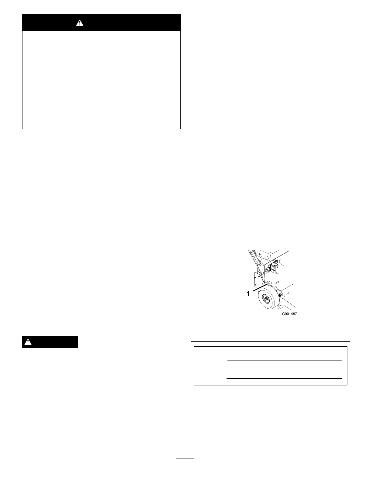
yourproductready.Figure1identiesthelocationofthe
modelandserialnumbersontheproduct.Writethenumbers
inthespaceprovided.
Important:Thisengineisequippedwithaspark
arrestermufer.ItisaviolationofCaliforniaPublic
ResourceCodeSection4442touseoroperate
theengineonanyforest-covered,brush-covered,
orgrass-coveredlandwithoutasparkarrester
mufermaintainedinworkingorder,ortheengine
constricted,equipped,andmaintainedforthe
preventionofre.Otherstatesorfederalareasmay
havesimilarlaws.
WARNING
Removingstandardoriginalequipmentpartsand
accessoriesmayalterthewarranty,traction,and
safetyofthemachine.FailuretouseoriginalToro
partscouldcauseseriousinjuryordeath.Making
unauthorizedchangestotheengine,fuelorventing
system,mayviolateEP AandCARBregulations.
Replaceallpartsincluding,butnotlimitedto,tires,
belts,blades,andfuelsystemcomponentswith
originalToroparts.
Theenclosed
informationregardingtheUSEnvironmentalProtection
Engine Owner's Man ual
issuppliedfor
Figure1
1.Modelandserialnumberlocation
ModelNo.
SerialNo.
Thismanualidentiespotentialhazardsandhassafety
messagesidentiedbythesafetyalertsymbol(Figure2),
whichsignalsahazardthatmaycauseseriousinjuryordeath
ifyoudonotfollowtherecommendedprecautions.
©2013—TheToro®Company
8111LyndaleAvenueSouth
Bloomington,MN55420
Contactusatwww.T oro.com.
2
PrintedintheUSA
AllRightsReserved
Page 3

Contents
Figure2
1.Safetyalertsymbol
Thismanualuses2wordstohighlightinformation.
Importantcallsattentiontospecialmechanicalinformation
andNoteemphasizesgeneralinformationworthyofspecial
attention.
Introduction..................................................................2
Safety...........................................................................4
SafeOperatingPractices...........................................4
ToroMowerSafety..................................................6
SlopeIndicator.......................................................7
SafetyandInstructionalDecals.................................8
ProductOverview.........................................................11
Controls...............................................................11
Specications........................................................12
Attachments/Accessories........................................12
Operation....................................................................13
AddingFuel...........................................................13
UsingFuelStabilizer/Conditioner............................13
FillingtheFuelTank...............................................14
CheckingtheEngine-oilLevel..................................14
ThinkSafetyFirst...................................................14
OperatingtheParkingBrake....................................14
StartingandStoppingtheEngine..............................14
OperatingtheBlade-controlLever(PTO)..................15
TheSafety-interlockSystem.....................................16
DrivingForwardorBackward..................................16
UsingtheLowerControlBar...................................16
StoppingtheMachine.............................................17
TransportingtheMachine........................................17
AdjustingtheFlowBafe........................................18
PositioningtheFlowBafe......................................18
SideDischargingorMulchingtheGrass.....................19
AdjustingtheHeightofCut.....................................19
AdjustingtheHandleHeight....................................20
AdjustingtheControlRods......................................21
Height-of-cutChart................................................22
Maintenance.................................................................23
RecommendedMaintenanceSchedule(s)......................23
Lubrication...............................................................24
LubricatingtheMachine..........................................24
LubricatingtheCasterandWheelBearings.................24
GreasingtheTransmissionCouplers.........................24
GreasingtheMowerBeltIdler..................................24
EngineMaintenance..................................................25
ServicingtheAirCleaner.........................................25
ServicingtheEngineOil..........................................25
ServicingtheSparkPlugs.........................................27
FuelSystemMaintenance...........................................28
ServicingtheFuelSystem........................................28
DriveSystemMaintenance.........................................30
CheckingtheTirePressure......................................30
CoolingSystemMaintenance......................................30
CleaningtheAir-intakeScreen..................................30
CleaningtheCoolingSystem....................................30
BrakeMaintenance....................................................31
ServicingtheBrakes................................................31
BeltMaintenance......................................................32
CheckingtheBelts..................................................32
ReplacingtheTractionDriveBelt.............................32
ReplacingtheDriveBelt..........................................32
ReplacingtheMowerBelt........................................32
3
Page 4

AdjustingtheMowerBeltTension............................34
MowerDeckMaintenance...........................................37
ServicingtheCuttingBlades.....................................37
AdjustingtheBladeBrake........................................40
ReplacingtheGrassDeector..................................41
Storage........................................................................41
Troubleshooting...........................................................43
Schematics...................................................................45
Safety
Note:Theadditionofattachmentsmadebyother
manufacturersthatdonotmeetAmericanNationalStandards
Institutecerticationwillcausenoncomplianceofthis
machine.
Improperlyusingormaintainingthemachinecanresult
ininjury.Toreducethepotentialforinjury,complywith
thesesafetyinstructionsandalwayspayattentiontothe
safetyalertsymbol,whichmeans
Danger
withtheinstructionmayresultinpersonalinjuryor
death.
—personalsafetyinstruction.Failuretocomply
SafeOperatingPractices
ThefollowinginstructionsareadaptedfromANSI
B71.4-2012.
Training
•ReadtheOperator'sManualandothertrainingmaterial.If
theoperator(s)ormechanic(s)cannotreadorunderstand
theinformationitistheowner'sresponsibilitytoexplain
thismaterialtothem.
•Becomefamiliarwiththesafeoperationoftheequipment,
operatorcontrols,andsafetysigns.
•Alloperatorsandmechanicsshouldbetrained.The
ownerisresponsiblefortrainingtheusers.
•Neverletchildrenoruntrainedpeopleoperateorservice
theequipment.Localregulationsmayrestricttheageof
theoperator.
•Theowner/usercanpreventandisresponsiblefor
accidentsorinjuriesoccurringtopeopleordamageto
property.
Caution, W ar ning ,
or
Preparation
•Evaluatetheterraintodeterminewhataccessoriesand
attachmentsareneededtoproperlyandsafelyperform
thejob.Onlyuseaccessoriesandattachmentsapproved
bythemanufacturer.
•Wearappropriateclothingincludinghardhat,safety
glasses,andhearingprotection.Longhair,looseclothing,
orjewelrymaygettangledinmovingparts.
•Inspecttheareawheretheequipmentistobeusedand
removeallobjectssuchasrocks,toys,andwirewhichcan
bethrownbythemachine.
•Checkthatoperator'spresencecontrols,safetyswitches,
andshieldsareattachedandfunctioningproperly .Donot
operateunlesstheyarefunctioningproperly.
Operation
•Lightningcancausesevereinjuryordeath.Iflightning
isseenorthunderisheardinthearea,donotoperate
themachine;seekshelter.
4
Page 5

•Neverrunanengineinanenclosedarea.
•Onlyoperateingoodlight,keepingawayfromholesand
hiddenhazards.
•Besurealldrivesareinneutralandparkingbrakeis
engagedbeforestartingtheengine.Onlystarttheengine
fromtheoperator'sposition.
•Besureofyourfootingwhileusingthismachine,
especiallywhenbackingup.Walk;donotrun.Never
operateonwetgrass.Reducedfootingcouldcause
slipping.
•Slowdownanduseextracareonhillsides.Besureto
travelsidetosideonhillsides.Turfconditionscanaffect
thestabilityofthemachine.Usecautionwhileoperating
neardrop-offs.
•Slowdownandusecautionwhenmakingturnsandwhen
changingdirectionsonslopes.
•Neverraisedeckwiththebladesrunning.
•NeveroperatewiththePTOshieldorotherguardsnot
securelyinplace.Besureallinterlocksareattached,
adjustedproperly,andfunctioningproperly.
•Neveroperatewiththedischargedeectorraised,
removedoraltered,unlessusingagrasscatcher.
•Donotchangetheenginegovernorsettingoroverspeed
theengine.
•Stoponlevelground,disengagedrives,engagethe
parkingbrake(ifprovided),andshutofftheenginebefore
leavingtheoperator'spositionforanyreason,including
emptyingthecatchersoruncloggingthechute.
•Stopequipmentandinspectbladesafterstrikingobjects
orifanabnormalvibrationoccurs.Makenecessary
repairsbeforeresumingoperations.
•Keephandsandfeetawayfromthecuttingunit.
•Lookbehindanddownbeforebackinguptobesureof
aclearpath.
•Nevercarrypassengersonthemachine.
•Keeppetsandbystandersaway.
•Slowdownandusecautionwhenmakingturnsand
crossingroadsandsidewalks.Stopbladesifnotmowing.
•Beawareofthemowerdischargedirectionanddonot
pointitatanyone.
•Donotoperatethemowerundertheinuenceofalcohol
ordrugs.
•Usecarewhenloadingorunloadingthemachineinto
orfromatrailerortruck.
•Usecarewhenapproachingblindcorners,shrubs,trees,
orotherobjectsthatmayobscurevision.
SafeHandlingofFuels
•Toavoidpersonalinjuryorpropertydamage,use
extremecareinhandlinggasoline.Gasolineisextremely
ammableandthevaporsareexplosive.
•Extinguishallcigarettes,cigars,pipes,andothersources
ofignition.
•Useonlyanapprovedfuelcontainer.
•Neverremovefuelcaporaddfuelwiththeengine
running.
•Allowenginetocoolbeforerefueling.
•Neverrefuelthemachineindoors.
•Neverstorethemachineorfuelcontainerwherethereis
anopename,spark,orpilotlightsuchasonawater
heateroronotherappliances.
•Neverllcontainersinsideavehicleoronatruckor
trailerbedwithaplasticliner.Alwaysplacecontainerson
thegroundawayfromyourvehiclebeforelling.
•Removeequipmentfromthetruckortrailerandrefuelit
ontheground.Ifthisisnotpossible,thenrefuelsuch
equipmentwithaportablecontainer,ratherthanfroma
fueldispensernozzle.
•Keepthenozzleincontactwiththerimofthefueltank
orcontaineropeningatalltimesuntilfuelingiscomplete.
•Donotuseanozzlelockopendevice.
•Iffuelisspilledonclothing,changeclothingimmediately.
•Neveroverllfueltank.Replacefuelcapandtighten
securely.
MaintenanceandStorage
•Disengagedrives,settheparkingbrake,stoptheengine
andremovethekeyordisconnectthespark-plugwire.
Waitforallmovementtostopbeforeadjusting,cleaning
orrepairingthemachine.
•Cleangrassanddebrisfromthecuttingunit,thedrives,
themufers,andtheenginetohelppreventres.Clean
upoilorfuelspillage.
•Lettheenginecoolbeforestoringanddonotstorenear
ame.
•Shutoffthefuelwhilestoringortransporting.Donot
storefuelnearamesordrainindoors.
•Parkthemachineonlevelground.Settheparkingbrake.
Neverallowuntrainedpersonneltoservicethemachine.
•Usejackstandstosupportcomponentswhenrequired.
•Carefullyreleasepressurefromcomponentswithstored
energy.
•Disconnectthebatteryorthespark-plugwirebefore
makinganyrepairs.Disconnectthenegativeterminal
rstandthepositivelast.Connectthepositiverstand
negativelast.
•Usecarewhencheckingtheblades.Wraptheblade(s)or
weargloves,andusecautionwhenservicingthem.Only
replaceblades.Neverstraightenorweldthem.
•Keephandsandfeetawayfrommovingparts.Ifpossible,
donotmakeadjustmentswiththeenginerunning.
•Keepallpartsingoodworkingconditionandallhardware
tightened.Replaceallwornordamageddecals.
•Tobestprotectyourinvestmentandmaintainoptimal
performanceofyourToroequipment,countonToro
genuineparts.Whenitcomestoreliability,Torodelivers
5
Page 6

replacementpartsdesignedtotheexactengineering
specicationsofourequipment.Forpeaceofmind,insist
onT orogenuineparts.
Hauling
•Usecarewhenloadingorunloadingthemachineintoa
trailerortruck.
•Usefullwidthrampsforloadingmachineintotraileror
truck.
•Tiethemachinedownsecurelyusingstraps,chains,cable,
orropes.Bothfrontandrearstrapsshouldbedirected
downandoutwardfromthemachine.
ToroMowerSafety
ThefollowinglistcontainssafetyinformationspecictoToro
productsandothersafetyinformationyoumustknow.
Thisproductiscapableofamputatinghandsandfeetand
throwingobjects.Alwaysfollowallsafetyinstructionsto
avoidseriousinjuryordeath.
Thisproductisdesignedforcuttingandrecyclinggrassor,
whenequippedwithagrassbagger,forcatchingcutgrass.
Anyuseforpurposesotherthanthesecouldprovedangerous
touserandbystanders.
Service
•Neverstorethemachineorfuelcontainerinsidewhere
thereisanopename,suchasnearawaterheateror
furnace.
•Keepnutsandboltstight,especiallythebladeattachment
bolts.Keepequipmentingoodcondition.
•Nevertamperwithsafetydevices.Checksafetysystems
forproperoperationbeforeeachuse.
•Useonlygenuinereplacementpartstoensurethatoriginal
standardsaremaintained.
•Checkbrakeoperationfrequently.Adjustandserviceas
required.
GeneralOperation
•Besuretheareaisclearofotherpeoplebeforemowing.
Stopthemachineifanyoneentersthearea.
•Donottouchequipmentorattachmentpartswhichmay
behotfromoperation.Allowtocoolbeforeattempting
tomaintain,adjustorservice.
•UseonlyToroapprovedattachments.Warrantymaybe
voidedifusedwithunapprovedattachments.
•Checkcarefullyforoverheadclearances(i.e.branches,
doorways,electricalwires)beforeoperatingunderany
objectsanddonotcontactthem.
SlopeOperation
Allslopesandrampsrequireextracaution.Ifyoufeeluneasy
onaslope,donotmowit.
•Removeobstaclessuchasrocks,treelimbs,etc.fromthe
mowingarea.
•Watchforholes,rutsorbumps.Tallgrasscanhide
obstacles.
•Usecautionneardrop-offs,ditches,orembankments.
Themachinecouldsuddenlyturnoverifawheelgoes
overtheedgeofaclifforditch,orifanedgecavesin.
•Useextracarewithgrasscatchersorotherattachments.
Thesecanchangethestabilityofthemachine.
•Keepallmovementonslopesslowandgradual.Donot
makesuddenchangesinspeedordirection.
•Mowslopessidetoside.
•Donotmowslopesgreaterthan20degrees.
6
Page 7
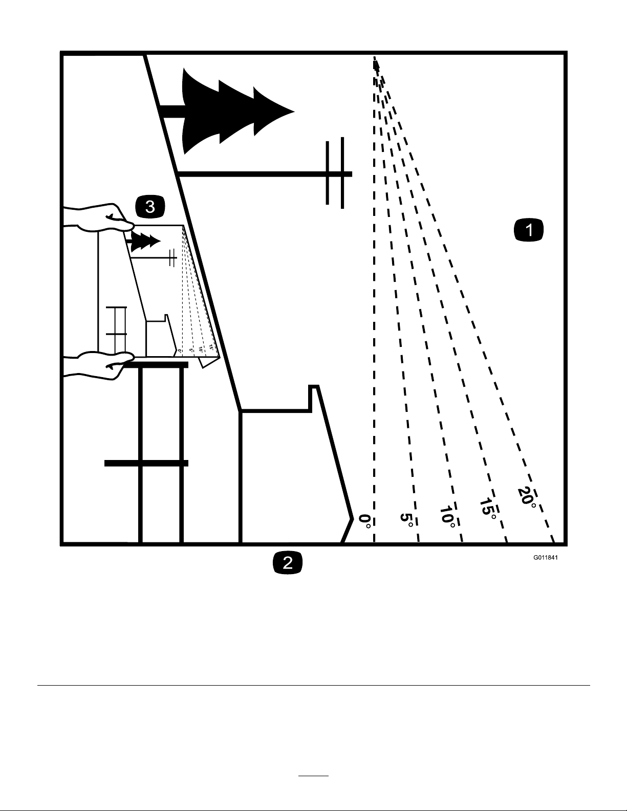
SlopeIndicator
G011841
Figure3
Thispagemaybecopiedforpersonaluse.
1.Themaximumslopeyoucansafelyoperatethemachineonis20degrees.Usetheslopecharttodeterminethedegreeofslope
ofhillsbeforeoperating.Donotoperatethismachineonaslopegreaterthan20degrees.Foldalongtheappropriateline
tomatchtherecommendedslope.
2.Alignthisedgewithaverticalsurface,atree,building,fencepole,etc.
3.Exampleofhowtocompareslopewithfoldededge.
7
Page 8

SafetyandInstructionalDecals
82- 2280
REV E R S E TRACT ION DR I V E
Safetydecalsandinstructionsareeasilyvisibletotheoperatorandarelocatednearanyareaofpotential
danger.Replaceanydecalthatisdamagedorlost.
1-403005
95-5537
1.ReadtheOperator's
Manualforinstructionson
operatingthecuttingblade
66-1340
82-2280
82-2290
2.Pushforwardtoengage
3.Pullbacktodisengage
98-0776
98-3256
8
Page 9
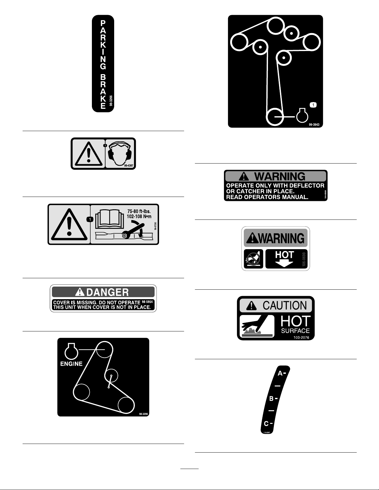
98-3266
98-4387
1.Warning—wearhearingprotection.
98-5130
1.Warning—readtheOperator'sManualforinstructionson
torquingthebladebolt/nutto75-80ft-lb(102-106N⋅m).
99-3943
ForModelwith3–BladeMowerDecks
1.Engine
104-8569
106-0699
98-5954
98-3296
ForModelswith2–BladeMowerDecks
103–2076
110-2067
9
Page 10
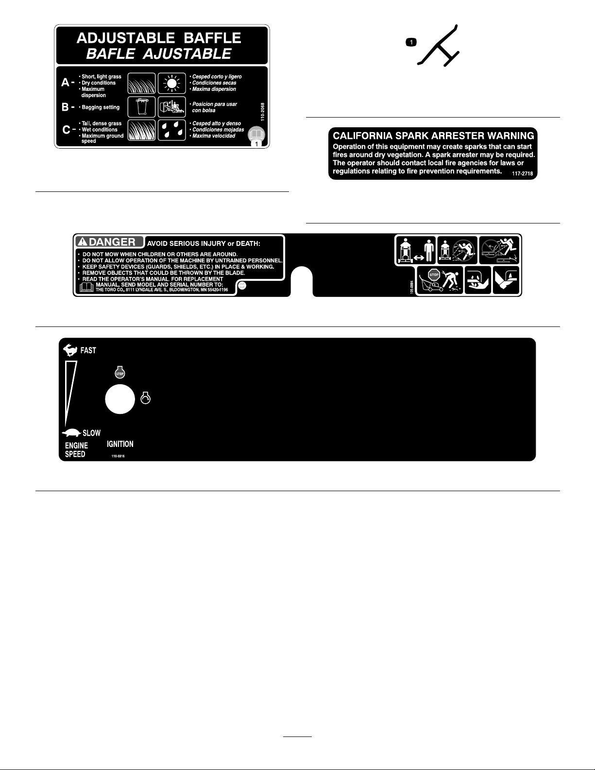
110-2068
1.ReadtheOperator'sManual.
Manufacturer'sMark
1.Indicatesthebladeisidentiedasapartfromtheoriginal
machinemanufacturer.
117–2718
(Model39674only)
105-0884
110-6916
10
Page 11

ProductOverview
G017539
Controls
Becomefamiliarwithallthecontrols(Figure5)beforeyou
starttheengineandoperatethemachine.
Figure4
1.Sidedischarge
2.Mowerdeck6.Handle
3.Recoil-starthandle7.Frontcasterwheel
4.Gastank
5.T-barcontrol
Figure5
1.Throttlecontrol7.Parkingbrake
2.Blade-controlbail
3.Powertake-offlever(PTO)
4.Gear-shiftlever
5.Uppercontrolbar11.Lowerhandle
6.Lowercontrolbar
lever—releasedposition
8.Choke
9.Ignitionswitch
10.Upperhandle
ThrottleControl
Thethrottlecontrolhas2positions:FastandSlow.
Blade-controlBail
Thebailisusedinconjunctionwiththeblade-controllever
(PTO)toengagetheclutchanddrivethemowerblades.
Releasingthebladecontrolbailwillstoptheenginewiththe
PTOengaged.
Blade-controlLever(PTO)
Thisleverisusedinconjunctionwiththeblade-controlbail
toengageanddisengagethemowerdeckbeltanddrivethe
mowerblades.
Gear-shiftLever
Thetransmissionhas5forwardspeeds,neutral,andreverse,
andhasanin-lineshiftpattern.
11
Page 12

Important:Donotshiftwhilethemachineismoving,
astransmissiondamagemayoccur.
UpperControlBar
Shifttothedesiredgearandpushforwardontheupper
controlbarandbladecontrolbailtoengageforwardtraction
operationandpullbacktobrakeforwardmovement.Pull
backonrightsideofuppercontrolbartoturnrightandleft
sidetoturnleft.
LowerControlBar
Shifttransmissiontoreverseandsqueezethelowercontrol
barandhandletogethertoengagetherearwardtractionassist.
Parking-brakeLever
Pullbackonuppercontrolbarandswingbrakeleverup
againsttheupperhandletosettheparkingbrake(Figure5).
IgnitionSwitch
Thisswitchisusedinconjunctionwithrecoilstarterandhas
twopositions:RunandOff.
RecoilStarter
Specications
Note:Specicationsanddesignaresubjecttochange
withoutnotice.
32-inchmowers:
Widthwithdeectordown116.3cm(45.8inches)
Length
Height
Weight
36-inchmowers:
Widthwithdeectordown118.4cm(46.6inches)
Length
Height
Weight
48-inchmowers:
Widthwithdeectordown161.3cm(63-1/2inches)
Length
Height
Weight
183cm(72inches)
104.1cm(41inches)
181kg(400lb)
188cm(74inches)
104.1cm(41inches)
209kg(460lb)
183.6cm(72-3/8inches)
104.1cm(41inches)
226kg(598lb)
Pulltherecoil-starthandletostarttheengine(notshown
inFigure4).
Fuel-shutoffValve
Closethefuel-shutoffvalvewhentransportingorstoringthe
machine.
Choke
Usethechoketostartacoldengine.
Attachments/Accessories
AselectionofToroapprovedattachmentsandaccessoriesis
availableforusewiththemachinetoenhanceandexpand
itscapabilities.ContactyourAuthorizedServiceDealeror
Distributororgotowww .Toro.comforalistofallapproved
attachmentsandaccessories.
12
Page 13

Operation
AddingFuel
•Forbestresults,useonlyclean,fresh(lessthan30days
old),unleadedgasolinewithanoctaneratingof87or
higher((R+M)/2ratingmethod).
•Ethanol:Gasolinewithupto10%ethanol(gasohol)
or15%MTBE(methyltertiarybutylether)byvolume
isacceptable.EthanolandMTBEarenotthesame.
Gasolinewith15%ethanol(E15)byvolumeisnot
approvedforuse.Neverusegasolinethatcontainsmore
than10%ethanolbyvolume,suchasE15(contains15%
ethanol),E20(contains20%ethanol),orE85(contains
85%ethanol).Usingunapprovedgasolinemaycause
performanceproblemsand/orenginedamagewhichmay
notbecoveredunderwarranty.
•Donotusegasolinecontainingmethanol.
•Donotstorefueleitherinthefueltankorfuelcontainers
overthewinterunlessafuelstabilizerisused.
•Donotaddoiltogasoline.
DANGER
Incertainconditions,fuelisextremelyammable
andhighlyexplosive.Areorexplosionfromfuel
canburnyouandothersandcandamageproperty.
•Fillthefueltankoutdoors,inanopenarea,when
theengineiscold.Wipeupanyfuelthatspills.
•Neverllthefueltankinsideanenclosedtrailer.
•Donotllthefueltankcompletelyfull.Addfuel
tothefueltankuntilthelevelis25mm(1inch)
belowthebottomofthellerneck.Thisempty
spaceinthetankallowsthefueltoexpand.
•Neversmokewhenhandlingfuel,andstayaway
fromanopenameorwherefuelfumesmaybe
ignitedbyaspark.
•Storefuelinanapprovedcontainerandkeepit
outofthereachofchildren.Donotbuymore
thana30-daysupplyoffuel.
•Donotoperatewithouttheentireexhaust
systeminplaceandinproperworkingcondition.
DANGER
Incertainconditionsduringfueling,static
electricitycancauseaspark,whichcanignitethe
fuelvapors.Areorexplosionfromfuelcanburn
youandothersandcandamageproperty.
•Alwaysplacefuelcontainersonthegroundaway
fromyourvehiclebeforelling.
•Donotllfuelcontainersinsideavehicleoron
atruckortrailerbedbecauseinteriorcarpets
orplastictruck-bedlinersmayinsulatethe
containerandslowthelossofanystaticcharge.
•Whenpractical,removefuel-poweredequipment
fromthetruckortrailerandfueltheequipment
withitswheelsontheground.
•Ifthisisnotpossible,thenrefuelsuch
equipmentonatruckortrailerfromaportable
container,ratherthanfromafuel-dispenser
nozzle.
•Ifafueldispensermustbeused,keepthe
nozzleincontactwiththerimofthefueltank
orcontaineropeningatalltimesuntilfuelingis
complete.
WARNING
Gasolineisharmfulorfatalifswallowed.Long-term
exposuretovaporscancauseseriousinjuryand
illness.
•Avoidprolongedbreathingofvapors.
•Keepfaceawayfromnozzleandgastankor
conditioneropening.
•Keepgasawayfromeyesandskin.
UsingFuel Stabilizer/Conditioner
Useafuelstabilizer/conditionerinthemachinetokeepthe
fuelfreshduringstorageof90daysorless.Ifyouarestoring
themachineforlonger,drainthefueltank;referto
(page41).
Storage
Important:Donotusefueladditivescontaining
methanolorethanol.
Addthecorrectamountoffuelstabilizer/conditionertothe
fuel,andfollowthedirectionsofthemanufacturer.
Note:Fuelstabilizer/conditionerismosteffectivewhen
mixedwithfreshgasoline.Tominimizethechanceofvarnish
depositsinthefuelsystem,usefuelstabilizeratalltimes.
13
Page 14
FillingtheFuelTank
1.Shuttheengineoffandsettheparkingbrake.
2.Cleanaroundthefuel-tankcapandremovethecap.
Addunleadedregulargasolinetothefueltank,untilthe
levelis6to13mm(1/4to1/2inch)belowthebottom
ofthellerneck.Thisspaceinthetankallowsgasoline
toexpand.Donotllthefueltankcompletelyfull.
3.Installthefuel-tankcapsecurely .Wipeupanygasoline
thatmayhavespilled.
CheckingtheEngine-oilLevel
Beforeyoustarttheengineandusethemachine,checktheoil
levelintheenginecrankcase;refertoCheckingtheEngine-oil
Level.
ThinkSafetyFirst
Carefullyreadallthesafetyinstructionsanddecalsinthe
safetysection.Knowingthisinformationcouldhelpyouor
anybystandersavoidinjury.
Theuseofprotectiveequipmentforeyes,hearing,feetand
headisrecommended.
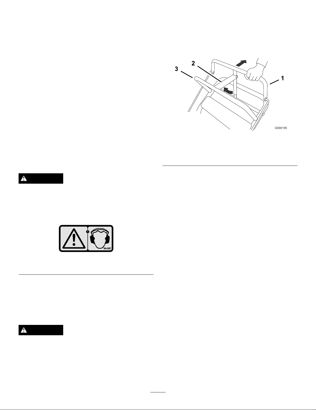
SettingtheParkingBrake
1.Pulltheuppercontrolbarrearwardandholditinthis
position(Figure7).
2.Lifttheparking-brakelockupandgraduallyreleasethe
uppercontrolbar.Thebrakelockshouldstayintheset
(locked)position(Figure7).
Figure7
1.Uppercontrolbar3.Fixedbar
2.Parking-brakelever—set
position
CAUTION
Thismachineproducessoundlevelsinexcessof
85dBAattheoperator'searandcancausehearing
lossthroughextendedperiodsofexposure.
Wearhearingprotectionwhenoperatingthis
machine.
Figure6
1.Warning—wearhearingprotection.
OperatingtheParkingBrake
Stoponlevelground,disengagedrives,engagetheparking
brake,stoptheengine,andremovethekey.Alwaysset
theparkingbrakewhenyoustopthemachineorleaveit
unattended.
CAUTION
Childrenorbystandersmaybeinjuredifthey
moveorattempttooperatethemachinewhileitis
unattended.
Alwaysremovetheignitionkeyandsettheparking
brakewhenleavingthemachineunattended,even
ifjustforafewminutes.
ReleasingtheParkingBrake
1.Pullrearwardontheuppercontrolbar.Lowerthe
parking-brakelocktothereleasedposition.
2.Graduallyreleasetheuppercontrolbar.
StartingandStoppingthe Engine
StartingtheEngine
1.Connectthewirestothesparkplugs.
2.Openthefuelvalve.
3.Disengagetheblade-control(PTO)leverandmovethe
shiftlevertotheneutralposition.
4.Settheparkingbrake.
5.Turntheignitionkeytotherunposition(
6.Tostartacoldengine,movethethrottlecontrol
midwaybetweenthefastandslowpositions.
7.Tostartawarmengine,movethethrottlecontrolto
thefastposition.
8.Pullthechokeknobtotheonpositioniftheengineis
cold(Figure8).
Note:Awarmorhotengineusuallydoesnotrequire
usingthechoke.
9.Grasptherecoilstarterhandlermlyandpullitout
untilpositiveengagementresults;thenpullthehandle
vigorouslytostarttheengine.Allowtheropetorecoil
slowly.
Figure8).
14
Page 15
Important:Donotpulltherecoilropetoitslimit
orreleasethestarterhandlewhenyoupullout
theropebecausetheropemaybreakortherecoil
assemblymaybedamaged.
10.Pushthechoketotheoffpositionastheenginewarms
up.
OperatingtheBlade-control Lever(PTO)
Theblade-controllever(PTO)engagesanddisengagespower
tothemowerblades.
11.Iftheengineiscold,allowittowarmupandthen
movethethrottlecontroltothefastposition.
StoppingtheEngine
Important:Inanemergency,youcanstoptheengine
immediatelybyturningtheignitionkeytothe
position.
1.Movethethrottlelevertotheslowposition(
2.Lettheengineidlefor30to60secondsbeforeturning
theignitionkeytotheoffposition.
3.Turntheignitionkeytotheoffposition(Figure8).
of f
Figure8).
EngagingtheMowerBlades
1.Toengagetheblades,squeezetheblade-controlbail
againsttheuppercontrolbar(Figure9).
2.Pushtheblade-controllever(PTO)rmlyforward,
untilitlatchesover-center.
3.Starttheengineandrepeattheproceduretoengagethe
mowerbladesiftheblade-controlbailisreleased.
Figure8
1.Blade-controllever(PTO)
2.Throttlelever
4.Settheparkingbrakeandremovethekey.
5.Disconnectthewiresfromthesparkplugstoprevent
thepossibilityofaccidentallystartingbeforestoringor
performingmaintenanceonthemachine.
6.Closethefuel-shutoffvalvebeforestoringor
transportingthemachine.
Important:Makesurethatthefuel-shutoff
valveisclosedbeforetransportingorstoringthe
machine,asfuelleakagemayoccur.
3.Ignitionkey
Figure9
1.Uppercontrolbar
2.Blade-controlbail
3.Blade-controllever(PTO)
DisengagingtheMowerBlades(PTO)
Todisengagetheblades,pulltheblade-controllever(PTO)
rearwardalltheway(Figure9).Theenginewillstopwhen
theblade-controlbailisreleasedwiththeblade-controllever
engaged.
Note:Itisnecessarytofullyandmanuallydisengagethe
blade-controllever.
15
Page 16

TheSafety-interlockSystem
3.Slowlypressontheuppercontrolbartomoveforward
(
Figure10).
CAUTION
Ifsafety-interlockswitchesaredisconnectedor
damagedthemachinecouldoperateunexpectedly,
causingpersonalinjury.
•Donottamperwiththeinterlockswitches.
•Checktheoperationoftheinterlockswitches
daily,andreplaceanydamagedswitchesbefore
operatingthemachine.
Thesafety-interlocksystemisdesignedtopreventtheengine
fromstartingwhen:
•Theblade-controllever(PTO)isengaged.
•Theignitionkeyisintheoffposition.
Thesafety-interlocksystemisalsodesignedtostopthe
enginewhen:
•The-bladecontrolbailisreleasedwiththeblade-control
lever(PTO)engaged.
•Theignitionswitchisturnedtotheoffposition.
TestingtheSafety-interlockSystem
Testthesafety-interlocksystembeforeyouusethemachine
eachtime.Ifthesafetysystemdoesnotoperateasdescribed
below,haveanAuthorizedServiceDealerrepairthesafety
systemimmediately .
1.Settheparkingbrake,disengagethePTO,andplace
thethrottleforward.
2.Starttheengine.
3.Withtheenginerunningsqueezetheblade-control
bailagainstuppercontrolbarandpushthe
mower-blade-controlleverforward.Themowerblades
shouldbeginrotating.
4.Withtheenginerunning,releasetheblade-controlbail.
Theengineshouldstop.
5.Starttheengineagain.
6.Withtheenginerunning,turntheignitionkeytothe
offposition.Theengineshouldstop.
Togostraight,applyequalpressuretobothendsofthe
uppercontrolbar(Figure10).
Toturn,releasepressureontheuppercontrolbarside
inthedirectionyouwanttoturn(Figure10).
Figure10
1.Uppercontrolbar
2.Lowercontrolbar4.Lowerhandle
3.Shiftlever
DrivingBackward
1.Togobackward,movetheshiftlevertothereverse
gear.
2.Releasetheparkingbrake;refertoReleasingthe
ParkingBrake.
3.Slowlysqueezethelowercontrolbarandlowerhandle
togethertomoverearward(
Figure10).
UsingtheLowerControlBar
Thisprocedureisfordrivingupacurb.Thiscanbe
performedwhiledrivingforwardorbackward.
DrivingForwardorBackward
Thethrottlecontrolregulatestheenginespeedasmeasured
inrpm(revolutionsperminute).Placethethrottlecontrolin
thefastpositionforbestmowingperformance.
DrivingForward
1.Togoforward,movetheshiftlevertoaforwardgear
(Figure10).
2.Releasetheparkingbrake;refertoReleasingthe
ParkingBrake.
Note:Somecurbsdonotallowthereardrivetirestocontact
thecurb.Ifthishappens,drivethemachineupthecurbatan
angle.
WARNING
Abladecanbebentordamagedwhendrivingup
acurb.Piecesofbladethatmaybethrowncould
seriouslyinjureorkillyouorbystanders.
Donotrunbladeswhiledrivingupacurbforward
orbackward.
16
Page 17

DrivingForwardupaCurb
1.Disengagethemowerblades.
2.Selecttherstgeartodrivethemachine.
3.Drivemachineuntilthecasterwheelscontactthecurb
(Figure11).
4.Liftthefrontofthemachinebypushingdownonthe
lowerhandle(
5.Drivethemachineuntilthedrivewheelscontactthe
curb(Figure11).
6.Lowerthefrontofthemachine(Figure11).
Note:Bothdrivewheelsshouldcontactthecurband
casterwheelsstraight.
7.Atthesametimeengagethelowercontrolbarandlift
uponthelowerhandletodriveoverthecurb(Figure
10andFigure11).
Figure11).
Note:Liftinguponthelowerhandlewillassistdriving
themachineupacurbandnotspinthedrivewheels.
Figure12
Note:Liftinguponthelowerhandlewillassistdriving
themachineupacurbandnotspinthedrivewheels.
Figure11
1.Lowercontrolbarengaged
andmowerinreverse
2.Pulluptoassistmachine
3.Lowercontrolbarengaged
andmowergoingforward
DrivingBackwardupaCurb
1.Disengagethemowerblades.
2.Selectreversetodrivethemachine.
3.Drivethemachineuntildrivewheelscontactcurb
(Figure11).
Note:Bothdrivewheelsshouldcontactthecurband
casterwheelsstraight.
4.Atthesametimeengagelowercontrolbarandliftup
onthelowerhandle(Figure10andFigure12).
1.Lowercontrolbar
(engaged)
2.Handle
StoppingtheMachine
Tostopthemachine,pullbackontheuppercontrolbar,
releasetheblade-controlbail,turntheignitionkeytotheoff
position,andsettheparkingbrake;referto
ParkingBrake(page14)
theignitionswitch.
.Remembertoremovethekeyfrom
Operatingthe
CAUTION
Childrenorbystandersmaybeinjuredifthey
moveorattempttooperatethemachinewhileitis
unattended.
Alwaysremovetheignitionkeyandsettheparking
brakewhenleavingthemachineunattended,even
ifjustforafewminutes.
TransportingtheMachine
Useaheavy-dutytrailerortrucktotransportthemachine.
Ensurethatthetrailerortruckhasallnecessarylightingand
markingasrequiredbylaw .Pleasecarefullyreadallthesafety
instructions.Knowingthisinformationcouldhelpyou,your
family,petsorbystandersavoidinjury.
Totransportthemachine:
1.Stoptheengine,removethekey,setthebrake,and
closethefuelvalve.
2.Securelyfastenthemachinetothetrailerortruckwith
straps,chains,cable,orropes.
3.Ifusingatrailer,securethetrailertothetowingvehicle
andinstallthesafetychains.
17
Page 18

AdjustingtheFlowBafe
g012676
1 2
G012677
G012678
Themowerdischargeowcanbeadjustedfordifferenttypes
ofmowingconditions.Positionthebafetogivethebest
qualityofcut.
1.DisengagethePTO ,movethemotioncontrolleversto
theneutrallockedpositionandsettheparkingbrake.
2.Stoptheengine,removethekey,andwaitforallmoving
partstostopbeforeleavingtheoperatingposition.
3.Toadjustthebafe,loosenthenut(
4.Adjustthebafeandnutintheslottothedesired
dischargeowandtightenthenut.
Figure13
1.Slot
2.Nut
PositioningtheFlowBafe
Figure13).
Figure14
PositionB
Usethispositionwhenbagging(Figure15).
Thefollowingguresareonlyrecommendationsforuse.
Adjustmentswillvarybygrasstype,moisturecontent,and
heightofgrass.
Note:Iftheenginepowerdrawsdownandthemower
groundspeedisthesame,openupthebafe.
PositionA
Thisisthefullrearposition(seeFigure14).Thesuggested
useforthispositionisafollows.
•Useforshort,lightgrassmowingconditions.
•Useindryconditions.
•Forsmallergrassclippings.
•Propelsgrassclippingsfartherawayfromthemower.
Figure15
PositionC
Thisisthefullopenposition.Thesuggesteduseforthis
positionisasfollows(Figure16).
•Useintall,densegrassmowingconditions.
•Useinwetconditions.
•Lowerstheenginepowerconsumption.
•Allowsincreasedgroundspeedinheavyconditions.
18
Page 19

G012679
Figure16
SideDischargingorMulching theGrass
Thismowerhasahingedgrassdeectorthatdisperses
clippingstothesideanddowntowardtheturf.
adjustmentrange,in6mm(1/4inch)increments,ofcutting
heightinanyaxleposition.Usethesamenumberofblade
spacersonallbladestoachievealevelcut(2aboveand
2below,1aboveand3below ,etc.).
1.Disengagethebladecontrol(PTO)leverandsetthe
parkingbrakes.
2.Stoptheengineandwaitforallmovingpartstostop
beforeleavingtheoperatingposition.
3.Holdthebladeboltandremovethenut(Figure17).
DANGER
Withoutthegrassdeector,dischargecover,or
completegrasscatcherassemblymountedin
place,youandothersareexposedtobladecontact
andthrowndebris.Contactwithrotatingmower
blade(s)andthrowndebriswillcauseinjuryor
death.
•Neverremovethegrassdeectorfromthemower
becausethegrassdeectorroutesmaterialdown
towardtheturf.Ifthegrassdeectorisever
damaged,replaceitimmediately.
•Neverputyourhandsorfeetunderthemower.
•Nevertrytocleardischargeareaormower
bladesunlessyoureleasethebailandthepower
takeoff(PTO)isoff.Rotatetheignitionkeyto
Off.Alsoremovethekeyandpullthewiresoff
thesparkplug(s).
AdjustingtheHeightofCut
Thismachinehasa26to108mm(1to4-1/4inch)range
fortheheightofcut.Thiscanbeachievedbyadjusting
thebladespacers,rearaxleheight,andfrontcasterspacers.
UsetheHeight-of-CutCharttoselectthecombinationof
adjustmentsrequired.
Figure17
1.Blade
2.Bladebolt5.Thinwasher
3.Curvedwasher
4.Slidetheboltdownthroughthespindle,andchange
thespacersasneeded(Figure17).
5.Installtheboltandcurvedwasher,addextraspacer(s),
andsecurethemwithathinwasherandanut(Figure
17).
6.Torquethebladeboltto75-80ft-lb(101-108N-m).
4.Spacer
6.Nut
AdjustingtheBladeHeight
Adjustthebladesbyusingthe4spacers(6mm)(1/4inch),
onthebladespindlebolts.Thisallowsfora25mm(1-inch)
19
Page 20

AdjustingtheAxleHeight
Adjusttheaxlepositiontotheselectedheight-of-cutsetting.
RefertotheHeight-of-CutChart.
1.Disengagethebladecontrol(PTO)leverandsetthe
parkingbrakes.
2.Stoptheengineandwaitforallmovingpartstostop
beforeleavingtheoperatingposition.
3.Loosen,butdonotremove,the2axlepivotboltsand
the2axleadjustmentbolts(Figure18).
Figure19
Figure18
1.Axlepivotbolt2.Axleadjustmentbolt
4.Placeajackundertherearcenteroftheengineframe.
Raisethebackendoftheengineframeupenoughto
removethefront2axleadjustmentbolts(Figure18).
Note:Usejackstandstosupportthemachine.
5.Raiseorlowertheengineframewiththejacksothat
youcaninstallthefront2axleadjustmentboltsinthe
desiredholelocation(Figure18).
Note:Useataperedpunchtohelpaligntheholes.
6.Tightenall4boltsandlowerthemower.
7.Adjustthecontrolrodsandthebrakelinkagesas
required.RefertoServicingtheBrakesandAdjusting
theControlRods.
1.Latchpin
2.Spacer,5mm(3/16inch)
3.Spacer,13mm(1/2inch)
2.Removethelatchpin,slidethecasterfromthesupport,
andchangethespacers(Figure19).
3.Installthecasterinthesupportandinsertthevpin
(Figure19).
AdjustingtheHandleHeight
Thehandlepositioncanbeadjustedtomatchtheoperator's
heightpreference.
1.Removehairpincotter,washerandclevispinsecuring
controlrodttingtoidlerbracket(
Figure20).
Important:Y oumustadjustthecontrolrods
andthebrakelinkagewhenyouchangetheaxle
positionsforpropertractionandbrakefunction.
AdjustingtheCasterPosition
1.UsingtheHeight-of-CutChart,adjustthecaster
spacerstomatchwiththeaxleholeselected(Figure19).
Figure20
1.Controlrod4.Clevispin
2.Controlrodtting
3.Idlerbracket6.Hairpincotterpin
5.Washer
2.Loosentheupperangebolts(3/8x1inch)andange
nutsecuringhandletorearframe(Figure21).
20
Page 21

Figure21
g018809
1
2
3
4
5
1.Upperhandle
2.Rearframe
3.Flangebolt(3/8x1inch)
4.Locknut(3/8inch)
5.Uppermountinghole
6.Lowermountinghole
3.Removethelowerangebolts(3/8x1inch)andange
nutssecuringhandletorearframe(Figure21).
4.Pivothandletodesiredoperatingpositionandinstall
lowerangebolts(3/8x1inch)andangenutsinto
mountingholes.Tightenallangebolts.
5.Threadrodttingupordownonroduntilproper
positionisattainedandinstallintottingtoidler
bracketwithclevispin,washerandhairpincotter.
6.Checktheparkingbrakeadjustment.RefertoChecking
theBrakesinBrakeMaintenance(page31).
AdjustingtheControlRods
1.Checkthegapbetweentheuppercontrolbarandthe
xedbarwiththewheeldrivefullyengaged.Thegap
willneedtobeapproximately25to32mm(1to1-1/4
inches);refertoFigure22.
Figure22
1.25to32mm(1to1-1/4
inches)gap
2.Fixedcontrolbar
3.Parking-brakelever
4.Uppercontrolbar
5.Controlrod
Note:Theuppercontrolbarandthexedbarmust
beparallelintheengaged,relaxedandbrakepositions.
2.Checktheoperation.Ifadjustmentisrequired,remove
thehairpincotterpinsecuringtherodtotheupper
controlbar.Threadtherodinoroutofthecontrolrod
ttingforproperpositionandinstallthecontrolrod
intotheuppercontrolbarwiththehairpincotterpin.
3.Afteradjustingthecontrolrods,checktheparking
brakeadjustment;refertoServicingtheBrakeinBrake
Maintenance(page31).
21
Page 22

Height-of-cutChart
Numberofspacers
13mm
Axleposition
A00
A01
A10
B01
B10
B11
B20
C
C
C
C
D21
D30
D31
D40
E31
E40
E41
(1/2inch)
11
20
21
30
belowcaster
5mm
(3/16inch)
26mm
29mm
(1-1/8inch)
35mm
(1-3/8inch)
35mm
(1-3/8inch)
41mm
(1-5/8inch)
45mm
(1-3/4inch)
51mm
48mm
(1-7/8inch)
55mm
(2-1/8inch)
57mm
(2-1/4inch)
64mm
(2-1/2inch)
61mm
(2-3/8inch)
64mm
(2-1/2inch)
70mm
(2-3/4inch)
76mm
73mm
(2-7/8inch)
79mm
(3-1/8inch)
82mm
(3-1/4inch)
Numberof1/4inchbladespacersbelowspindle
43210
(1inch)
(2inch)
(3inch)
32mm
(1-1/4inch)
35mm
(1-3/8inch)
41mm
(1-5/8inch)
41mm
(1-5/8inch)
48mm
(1-7/8inch)
51mm
(2inch)
57mm
(2-1/4inch)
54mm
(2-1/8inch)
60mm
(2-3/8inch)
64mm
(2-1/2inch)
70mm
(2-3/4inch)
67mm
(2-5/8inch)
70mm
(2-3/4inch)
76mm
(3inch)
82mm
(3-1/4inch)
79mm
(3-1/8inch)
86mm
(3-3/8inch)
89mm
(3-1/2inch)
38mm
(1-1/2inch)
41mm
(1-5/8inch)
48mm
(1-7/8inch)
48mm
(1-7/8inch)
54mm
(2-1/8inch)
57mm
(2-1/4inch)
64mm
(2-1/2inch)
60mm
(2-3/8inch)
67mm
(2-5/8inch)
70mm
(2-3/4inch)
76mm
(3inch)
73mm
(2-7/8inch)
76mm
(3inch)
82mm
(3-1/4inch)
89mm
(3-1/2inch)
86mm
(3-3/8inch)
92mm
(3-5/8inch)
95mm
(3-3/4inch)
45mm
(1-3/4inch)
48mm
(1-7/8inch)
54mm
(2-1/8inch)
54mm
(2-1/8inch)
60mm
(2-3/8inch)
64mm
(2-1/2inch)
70mm
(2-3/4inch)
67mm
(2-5/8inch)
73mm
(2-7/8inch)
76mm
(3inch)
83mm
(3-1/4inch)
79mm
(3-1/8inch)
82mm
(3-1/4inch)
89mm
(3-1/2inch)
95mm
(3-3/4inch)
92mm
(3-5/8inch)
98mm
(3-7/8inch)
102mm
(4inch)
51mm
(2inch)
54mm
(2-1/8inch)
60mm
(2-3/8inch)
60mm
(2-3/8inch)
67mm
(2-5/8inch)
70mm
(2-3/4inch)
76mm
(3inch)
73mm
(2-7/8inch)
79mm
(3-1/8inch)
83mm
(3-1/4inch)
89mm
(3-1/2inch)
86mm
(3-3/8inch)
89mm
(3-1/2inch)
95mm
(3-3/4inch)
102mm
(4inch)
98mm
(3-7/8inch)
105mm
(4-1/8inch)
108mm
(4-1/4inch)
22
Page 23

Maintenance
Note:Determinetheleftandrightsidesofthemachinefromthenormaloperatingposition.
RecommendedMaintenanceSchedule(s)
MaintenanceService
Interval
Aftertherst8hours
Aftertherst25hours
Beforeeachuseordaily
Every25hours
Every50hours
Every100hours
Every200hours
MaintenanceProcedure
•Changetheengineoil.
•Checkthemowerbelttension.
•Checkthemowerbelttension.
•Checkthesafetysystem.
•Greasethecasterwheelsandcasterpivot.
•Checktheengine-oillevel.
•Cleantheair-intakescreen.
•Checkthebrakes.
•Inspecttheblades.
•Cleanthemowerdeck.
•Cleanthefoamair-cleanerelement.
•Greasethemowerbeltidler.
•Checkthepaperair-cleanerelement.
•Checkthetirepressure.
•Checkthebelts.
•Checkthemowerbelttension.
•Changetheengineoil.
•Checkthesparkplugs.
•Checkandcleantheengine-coolingnsandshrouds.
•Replacethepaperair-cleanerelement.
•Changetheoillter.
•Replacethefuellter.
•Replacethefuelventlter.
Every250hours
Every400hours
Beforestorage
•Greasethetransmissioncouplers(moreoftenindirtyordustyconditions).
•Greasethewheelbearings(moreoftenindirtyordustyconditions).
•Paintchippedsurfaces.
•Performallmaintenanceprocedureslistedabovebeforestorage.
Important:Refertoyourengineoperator'smanualforadditionalmaintenanceprocedures.
CAUTION
Ifyouleavethekeyintheignitionswitch,someonecouldaccidentlystarttheengineandseriouslyinjure
youorotherbystanders.
Removethekeyfromtheignitionanddisconnectthespark-plugwire(s)fromthesparkplug(s)beforeyou
doanymaintenance.Setthewireasidesothatitdoesnotaccidentallycontactthesparkplug.
23
Page 24

Lubrication
GreaseType:#2general-purposelithium-basedor
molybdenum-basedgrease
LubricatingtheMachine
1.DisengagethePTOandsettheparkingbrake.
2.Stoptheengine,removethekey,andwaitforallmoving
partstostopbeforeleavingtheoperatingposition.
3.Cleanthegreasettingswitharag.Makesuretoscrape
anypaintoffthefrontofthetting(s).
4.Connectagreaseguntothetting.Pumpgrease
intothettingsuntilgreasebeginstooozeoutofthe
bearings.
5.Wipeupanyexcessgrease.
Figure24
GreasingtheMowerBeltIdler
Greasethettingonthemowerbelt-idlerarmpivot(Figure
25).
LubricatingtheCasterand WheelBearings
1.Lubricatethefrontwheelbearingsandfrontspindles
(Figure23).
2.Lubricatethedrivewheelbearings(Figure23).
Figure23
Note:Removethemowerdeckcovertoaccessthegrease
ttingforthemowerbelt-idlerarm.
Figure25
32-inchand36-inchmowerdeck
GreasingtheTransmission Couplers
Lubricatethetransmissioncouplersandidlerarmpivots
locatedinthebackofthemachine(Figure24).
Figure26
48-inchmowerdeck
24
Page 25

EngineMaintenance
ServicingtheAirCleaner
CleaningtheFoamAir-cleanerElement
1.Washthefoamelementinliquidsoapandwarmwater.
Whentheelementisclean,rinseitthoroughly.
2.Drytheelementbysqueezingitinacleancloth.
ServiceInterval/Specication
ServiceInterval:Every25hours—Cleanthefoam
air-cleanerelement.
Every50hours—Checkthepaperair-cleanerelement.
Every200hours—Replacethepaperair-cleaner
element.
Note:Servicetheaircleanermorefrequently(everyfew
operatinghours)iftheoperatingconditionsareextremely
dustyorsandy.
Important:Donotoilthefoamorpaperelement.
RemovingtheFoamandPaper
Elements
1.DisengagethePTOandsettheparkingbrake.
2.Stoptheengine,removethekey,andwaitforallmoving
partstostopbeforeleavingtheoperatingposition.
3.Cleanaroundtheaircleanertopreventdirtfrom
gettingintotheengineandcausingdamage(Figure27).
4.Unscrewthecoverknobsandremovetheair-cleaner
cover(Figure27).
5.Unscrewthehoseclampandremovetheaircleaner
assembly(Figure27).
6.Carefullypullthefoamelementoffthepaperelement
(Figure27).
Important:Replacethefoamelementifitistorn
orworn.
ServicingthePaperAir-cleanerElement
1.Donotcleanthepaperlter,replaceit(Figure27).
2.Inspecttheelementfortears,anoilylm,ordamageto
therubberseal.
3.Replacethepaperelementifitisdamaged.
InstallingtheFoamandPaperElements
Important:Topreventenginedamage,alwaysoperate
theenginewiththecompletefoamandpaperaircleaner
assemblyinstalled.
1.Carefullyslidethefoamelementontothepaper
air-cleanerelement(Figure27).
2.Placetheaircleanerassemblyontotheaircleanerbase
andsecureitwiththe2wingnuts(
3.Placetheair-cleanercoverintopositionandtighten
thecoverknob(Figure27).
Figure27).
ServicingtheEngineOil
ServiceInterval:Beforeeachuseordaily—Checkthe
engine-oillevel.
Aftertherst8hours—Changetheengineoil.
Every100hours—Changetheengineoil.
Figure27
1.Cover
2.Hoseclamp4.Foamelement
3.Paperelement
Every200hours—Changetheoillter.
Note:Changetheoilmorefrequentlywhentheoperating
conditionsareextremelydustyorsandy.
OilType:Detergentoil(APIserviceSF ,SG,SH,SJorSL)
CrankcaseCapacity:1.7L(1.8USqt)withthelter
removed;1.5L(1.6USqt)withoutthelterremoved
Viscosity:Refertothetable(Figure28).
25
Page 26

ChangingtheEngineOil
1.Parkthemachinesothatthedrainsideisslightlylower
thantheoppositesidetoensurethattheoildrains
completely.
2.DisengagethePTOandsettheparkingbrake.
3.Stoptheengine,removethekey,andwaitforallmoving
partstostopbeforeleavingtheoperatingposition.
4.Slidethedrainhoseovertheoildrainvalve.
5.Placeapanbelowthedrainhose.Rotateoildrainvalve
toallowoiltodrain(Figure30).
Figure28
CheckingtheEngine-oilLevel
1.Parkthemachineonalevelsurface.
2.DisengagethePTOandsettheparkingbrake.
3.Stoptheengine,removethekey,andwaitforallmoving
partstostopbeforeleavingtheoperatingposition.
4.Cleanaroundtheoildipstick(Figure29)sothatdirt
cannotfallintothellerholeanddamagetheengine.
6.Whenoilhasdrainedcompletely ,closethedrainvalve.
7.Removethedrainhose(
Figure30).
Note:Disposeoftheusedoilatarecyclingcenter.
Figure29
1.Oildipstick
2.Fillertube
5.Unscrewtheoildipstickandwipetheendclean(Figure
29).
6.Slidetheoildipstickfullyintothellertube,butdonot
threaditontothetube(Figure29).
7.Pullthedipstickoutandlookattheend.Iftheoillevel
islow,slowlypouronlyenoughoilintothellertube
toraisetheleveltotheFullmark.
Important:Donotoverllthecrankcasewithoil
andruntheengine;enginedamagecanresult.
Figure30
1.Oildrainvalve2.Oildrainhose
8.Slowlypourapproximately80%ofthespeciedoil
intothellertube(
Figure29).
9.Checktheoillevel;refertoCheckingtheEngineOil
Level.
10.SlowlyaddtheadditionaloiltobringittotheFull
mark.
ChangingtheOilFilter
Note:Changetheoilltermorefrequentlywhenthe
operatingconditionsareextremelydustyorsandy.
1.Draintheoilfromtheengine;refertoChangingthe
EngineOil.
2.Removetheoldlter(
26
Figure31).
Page 27

Figure31
1
1.Oillter
2.Adapter
3.Applyathincoatofnewoiltotherubbergasketon
thereplacementlter(Figure31).
4.Installthereplacementoilltertothelteradapter,
turntheoillterclockwiseuntiltherubbergasket
contactsthelteradapter,thentightenthelteran
additional3/4turn(
Figure31).
5.Fillthecrankcasewiththepropertypeofnewoil;refer
toServicingtheEngineOil.
6.Runtheengineforabout3minutes,stoptheengine,
andcheckforoilleaksaroundtheoillteranddrain
valve.
7.Checktheengineoillevelandaddoilifneeded.
8.Wipeupanyspilledoil.
ServicingtheSparkPlugs
ServiceInterval:Every100hours—Checkthesparkplugs.
Ensurethattheairgapbetweenthecenterelectrodeandthe
sideelectrodeiscorrectbeforeinstallingeachsparkplug.Use
aspark-plugwrenchforremovingandinstallingthespark
plugsandagappingtoolorafeelergaugetocheckandadjust
theairgap.Installnewsparkplugsifnecessary.
Figure32
1.Spark-plugwire/sparkplug
4.Cleanaroundthesparkplugstopreventdirtfrom
fallingintotheengineandpotentiallycausingdamage.
5.Removethesparkplugsandthemetalwashers.
CheckingtheSparkPlugs
1.Lookatthecenterofthesparkplugs(Figure33).If
youseelightbrownorgrayontheinsulator,theengine
isoperatingproperly.Ablackcoatingontheinsulator
usuallymeansthattheaircleanerisdirty.
2.Ifneeded,cleanthesparkplugwithawirebrushto
removecarbondeposits.
Type:Champion®RCJ8Yorequivalent
AirGap:0.75mm(0.030inch)
RemovingtheSparkPlugs
1.DisengagethePTOandsettheparkingbrake.
2.Stoptheengine,removethekey,andwaitforallmoving
partstostopbeforeleavingtheoperatingposition.
3.Disconnectthewiresfromthesparkplugs(
Figure32).
Figure33
1.Centerelectrode;insulator3.Airgap(nottoscale)
2.Sideelectrode
Important:Alwaysreplacethesparkplugswhen
theyhavewornelectrodes,anoilylm,ora
crackedinsulator.
3.Checkthegapbetweenthecenterelectrodeandthe
sideelectrode(
Figure33).Bendthesideelectrode
(Figure33)ifthegapisnotcorrect.
27
Page 28

InstallingtheSparkPlugs
1.Installthesparkplugsandthemetalwasher.Ensure
thattheairgapissetcorrectly.
2.Tightenthesparkplugsto22N-m(16ft-lb).
FuelSystem
Maintenance
3.Connectthewirestothesparkplugs(Figure33).
ServicingtheFuelSystem
DANGER
Incertainconditions,gasolineisextremely
ammableandhighlyexplosive.Areorexplosion
fromgasolinecanburnyouandothersandcan
damageproperty.
•Draingasolinefromthefueltankwhenthe
engineiscold.Dothisoutdoorsinanopenarea.
Wipeupanygasolinethatspills.
•Neversmokewhendraininggasoline,andstay
awayfromanopenameorwhereasparkmay
ignitethegasolinefumes.
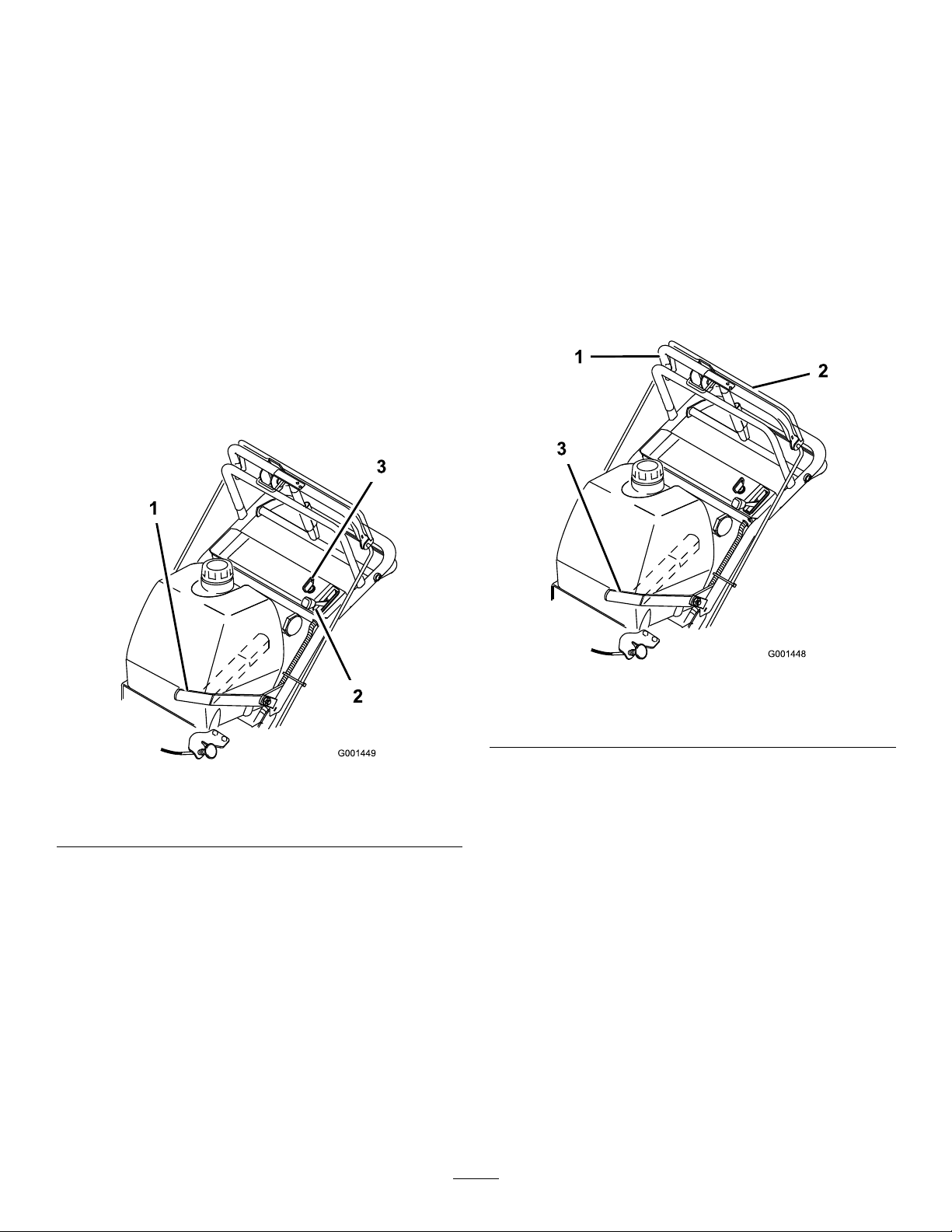
DrainingtheFuelTank
1.Parkthemachineonalevelsurfacetoensurethatthe
fueltankdrainscompletely;thendisengagethepower
take-off(PTO),settheparkingbrake,andturnthe
ignitionkeytotheoffposition.Removethekey .
2.Closethefuel-shutoffvalveatthefueltank(Figure34).
3.Squeezetheendsofthehoseclamptogetherandslide
itupthefuellineawayfromfuellter(Figure34).
4.Pullthefuellineoffthefuellter(Figure34).Open
thefuel-shutoffvalveandallowthegasolinetodrain
intoagascanordrainpan.
Note:Nowisthebesttimetoinstallanewfuellter
becausethefueltankisempty.RefertoReplacingthe
FuelFilter.
5.Installthefuellineontothefuellter.Slidethehose
clampclosetothevalvetosecurethefuelline.
1.Fuel-shutoffvalve2.Clamp
28
Figure34
Page 29

ReplacingtheFuelFilter
g014686
1 2
ServiceInterval:Every200hours/Yearly(whichevercomes
rst)
Neverinstalladirtylterifitisremovedfromthefuelline.
Note:Notehowthefuellterisinstalledinordertoinstall
thenewltercorrectly.
Note:Wipeupanyspilledfuel.
1.DisengagethePTOandsettheparkingbrake.
2.Stoptheengine,removethekey,andwaitforallmoving
partstostopbeforeleavingtheoperatingposition.
3.Closethefuel-shutoffvalveatthefueltank(
4.Squeezetheendsofthehoseclampstogetherandslide
themawayfromthelter(Figure35).
Figure35
1.Hoseclamp3.Filter
2.Fuelline
Figure34).
Figure36
1.Fuelventlter2.Rightsideofengine
5.Removethelterfromthefuellines.
6.Installanewlterandmovethehoseclampscloseto
thelter.
7.Openthefuel-shutoffvalveatthefueltank(Figure34).
8.Checkforfuelleaks,andrepairifneeded.
9.Wipeupanyfuelthatspilled.
ServicingtheFuelVentSystem
ServiceInterval:Every200hours/Yearly(whichevercomes
rst)
1.DisengagethePTOandsettheparkingbrake.
2.Stoptheengine,removethekey,andwaitforallmoving
partstostopbeforeleavingtheoperatingposition.
3.Removetheexistingfuelventlter(
4.Installanewlter.
Figure36).
29
Page 30

DriveSystem
CoolingSystem
Maintenance
CheckingtheTirePressure
ServiceInterval:Every50hours/Monthly(whichever
comesrst)
Maintaintheairpressureinthereartiresat83to97kPa(12
to14psi).Uneventirepressurecancauseanunevencut.
Note:Thefronttiresaresemi-pneumatictiresanddonot
requireairpressuremaintenance.
Maintenance
CleaningtheAir-intakeScreen
Beforeeachuse,removeanybuildupofgrass,dirt,or
otherdebrisfromthecylinderandcylinder-headcooling
ns,theair-intakescreenontheywheelend,andthe
carburetor-governorleversandlinkage.Thiswillhelpensure
adequatecoolingandcorrectenginespeedandwillreduce
thepossibilityofoverheatingandmechanicaldamagetothe
engine.
CleaningtheCoolingSystem
ServiceInterval:Every100hours/Yearly(whichevercomes
rst)
Cleantheairintakescreenfromgrassanddebrisbeforeeach
use.
1.DisengagethePTOandsettheparkingbrake.
2.Stoptheengine,removethekey,andwaitforallmoving
partstostopbeforeleavingtheoperatingposition.
Figure37
3.Removetheair-intakescreen,therecoilstarter,and
thefanhousing(Figure38).
4.Cleanthedebrisandgrassfromtheengineparts.
5.Installtheair-intakescreen,therecoilstarter,andthe
fanhousing(Figure38).
1.Air-intakescreen4.Bolt
2.Fanhousing5.Nut
3.Recoilstarter
30
Figure38
Page 31

BrakeMaintenance
ServicingtheBrakes
3.Checkthebrakebeforeyouadjustit;refertoChecking
theBrakes.
4.Releasetheparkingbrake;refertoReleasingthe
ParkingBrakeinOperation.
Beforeeachuse,checkbrakesonbothalevelsurfaceand
slope.
Alwayssettheparkingbrakewhenyoustopthemachine
orleaveitunattended.Iftheparkingbrakedoesnothold
securely,anadjustmentisrequired.
CheckingtheBrakes
1.Parkthemachineonalevelsurface,disengagethe
bladecontrol(PTO).
2.Stoptheengine,removethekey,andwaitforallmoving
partstostopbeforeleavingtheoperatingposition.
3.Applytheparkingbrake.Thewheelsmustlockwhen
youtrytopushthemachineforward.
4.Ifthewheelsdonotlock,adjustthebrakes.Referto
AdjustingtheBrakes.
5.Releasethebrakeandpressuppercontrolbarvery
lightly,approximately13mm(1/2inch).Thewheels
shouldrotatefreely;ifnot,refertoAdjustingthe
Brakes.
5.Toadjustthebrake,rotatethewingnutsonthebrake
Figure39).Turnthewingnutsclockwiseto
rods(
tightenthebrakeandcounterclockwisetoloosenthe
brake.
Figure39
1.Brakerod2.Wingnut
Note:Controlbarshouldbeparallelwiththe
referencebarwhenproperlyadjusted.
AdjustingtheBrakes
Thebrakeleverisontheuppercontrolbar.Iftheparking
brakedoesnotholdsecurely,anadjustmentisrequired.
1.Parkthemachineonalevelsurface,disengagethe
PTO,andsettheparkingbrake.
2.Stoptheengine,removethekey,andwaitforallmoving
partstostopbeforeleavingtheoperatingposition.
6.Checkthebrakeoperationagain;refertoChecking
theBrakes.
Important:Withtheparkingbrakereleased,the
rearwheelsmustrotatefreelywhenyoupushthe
mower.Ifbrakeactionandfreewheelrotation
cannotbeachievedcontactyourservicedealer
immediately.
31
Page 32

BeltMaintenance
CheckingtheBelts
ServiceInterval:Every50hours/Monthly(whichever
comesrst)—Checkthebelts.
Checkthebeltsforcracks,frayededges,burnmarks,wear,
signsofoverheating,oranyotherdamage.Replaceany
damagedbelts.
ReplacingtheTractionDrive Belt
1.Removethehairpincottersecuringthebrakerodto
thebrakearmtorelaxthebeltidlertension(Figure40).
2.Removethebottomboltandloosenthetopboltofthe
shieldtorotateitforbeltclearance(Figure40).
3.Liftthebeltpasttheidlerandoffthedrivepulley
(Figure40).
4.Raisethewheeloffthegroundenoughtoallowfor
beltremoval.
5.Replacethetractiondrivebelt.
6.Securetheshieldwiththepreviouslyremovedboltand
tightenthebolts(Figure40).
7.Securethebrakerodtothebrakearmwiththehairpin
cotter(Figure40).
4.Removethemowerbelt(Figure41).
Figure41
1.Idlerpulleyinslot4.Beltguide
2.Tractionbelt
3.Mowerbelt6.Mowerbelt
5.Loosenthepivotboltenoughtoslidetheidlerpulleyin
theslotandremovethetractionbeltfromtheengine
andthedrivepulleys(Figure41).
6.Installthenewdrivebeltaroundtheengineandthe
drivepulleys(Figure41).
7.Slidetheidlerpulleyintheengineframetotensionthe
tractionbelt(Figure41).
8.Installthemowerbelt(Figure41).
9.Checkthebeltguideundertheengineframeforthe
properadjustment(Figure41).
5.19mm(3/4inch)
Figure40
1.Hairpincotter
2.Brakerod4.Drivebelt
3.Shield
ReplacingtheDriveBelt
1.Disengagetheblade-control(PTO)leverandsetthe
parkingbrakes.
2.Stoptheengineandwaitforallmovingpartstostop
beforeleavingtheoperatingposition.
3.Raisetherearofthemachineandholditupwithjack
stands.
Note:Thedistancebetweenthebeltguideandmower
beltshouldbe19mm(3/4inch)whenthemower
beltisengaged.Adjustthebeltifnecessary.The
disengagedbeltshouldnotdragorfalloffthepulley
whentheguidesareproperlyadjusted.
ReplacingtheMowerBelt
Important:Thebrakeneedstobeadjustedwhenthe
belttensionorthebrakelinkageisadjusted.
1.Disengagetheblade-control(PTO)leverandsetthe
parkingbrakes.
2.Stoptheengineandwaitforallmovingpartstostop
beforeleavingtheoperatingposition.
3.Removetheknobsandthebeltcoveronthemower.
4.Removetheidlerpulleyandthewornbelt.
5.Installthenewmowerbelt.
6.Installtheidlerpulley.
7.Engagetheblade-control(PTO)leverandcheck
thebelttension.RefertoAdjustingtheMowerBelt
Tension.
32
Page 33

Note:Thepropermowerbelttensionis44to67N-m
(10to15ft-lb)withthebeltdeected13mm(1/2inch)
halfwaybetweenthepulleys(Figure45orFigure46).
8.Engagetheblade-control(PTO)lever.
9.Checktheclearancebetweenthebellcrankandthe
transmissionoutputshaft(Figure42).
Figure42
1.2to3mm(1/16to1/8inch)
2.Bellcrank
3.Transmissionoutputshaft6.Clevis
4.Hairpincotter
5.Clevispin
Figure43
32-inchand36-inchmowerdeck
1.13mm(1/2inch)deection
here
2.Assistarm5.Turnbuckle
3.Frontstop
4.Locknut
Note:Theclearanceshouldbe2to3mm(1/16to
1/8inch).
10.Removethehairpincotterpinandtheclevispinfrom
thebellcrank.
11.Rotatetheclevisclockwiseontherodtoincreasethe
clearance;rotateitcounterclockwisetodecreaseit
Figure42).
(
12.Disengagetheblade-control(PTO)lever.
Note:Iftheassistarmdoesnotcontactthefrontstop
onthemowerdeck(Figure43orFigure44),adjustthe
clevistobringthebellcrankclosertothetransmission
outputshaft(Figure42).
Figure44
48-inchmowerdeck
1.13mm(1/2inch)deection
here
2.Assistarm5.Turnbuckle
3.Frontstop
4.Locknut
13.Checkthebeltguideundertheengineframeforthe
properadjustment(Figure41).
Note:Thedistancebetweenthebeltguideandthe
mowerbeltshouldbe32mm(1-1/4inch)whenyou
engagethemowerbelt.Adjustthemowerbeltas
33
Page 34

necessary.Thedisengagedbeltshouldnotdragorfall
offthepulleywhentheguidesareproperlyadjusted.
AdjustingtheMowerBelt Tension
AdjustingtheTensionfor32-inchand
36-inchMowerDecks
ServiceInterval:Aftertherst8hours—Checkthemower
belttension.
Aftertherst25hours—Checkthemowerbelt
tension.
Every50hours—Checkthemowerbelttension.
Important:Thebrakeneedstobeadjustedwhenthe
belttensionorthebrakelinkageisadjusted.
Important:Thebeltmustbetightenoughtonotslip
duringheavyloadswhilecuttinggrass.Over-tensioning
thebeltwillreducethespindlebearinglife,thebeltlife,
andtheidlerpulleylife.
Figure45
32-inchand36-inchmowerdeck
1.Mowerbeltwith13mm
(1/2inch)deection
6.Tightenthelocknutontheturnbuckle.
2.Idlerpulley
Thebeltmustbetightenoughsothatitdoesnotslipduring
heavyloadswhilecuttinggrass,andover-tensioningwill
reducebeltandspindlebearinglife.
1.Disengagetheblade-control(PTO)leverandsetthe
parkingbrakes.
2.Stoptheengineandwaitforallmovingpartstostop
beforeleavingtheoperatingposition.
3.Loosenthelocknutontheturnbuckle(Figure45).
4.Rotatetheturnbuckletowardtherearofthemowerto
increasethetensiononthebelt.Rotatetheturnbuckle
towardthefrontofthemowertodecreasethetension
onthebelt(Figure45).
Note:Theeyeboltthreadsonbothendsofthe
turnbuckleshouldbeengagedaminimumof8mm
(5/16inch).
5.Engagetheblade-controllever(PTO)andcheckthe
belttension.Adjustthetensionuntilitiscorrect.
Note:Thepropermowerbelttensionis44to67N-m
(10to15ft-lb)withthebeltdeected13mm(1/2inch)
halfwaybetweenthepulleys(Figure45).
7.Checkthebladebrakeadjustment;refertoAdjusting
theBladeBrake.
AdjustingtheTensionfor48-inch
MowerDecks
Important:Thebeltmustbetightenoughtonotslip
duringheavyloadswhilecuttinggrass.Over-tensioning
thebeltwillreducethespindlebearinglife,thebeltlife
andtheidlerpulleylife.
Important:Thebrakeneedstobeadjustedwhenthe
belttensionorthebrakelinkageisadjusted.
1.Disengagetheblade-control(PTO)leverandsetthe
parkingbrakes.
2.Stoptheengineandwaitforallmovingpartstostop
beforeleavingtheoperatingposition.
3.Loosenthelocknutontheturnbuckle(Figure47).
4.Rotatetheturnbuckletowardtherearofthemowerto
increasethetensiononthebelt.Rotatetheturnbuckle
towardthefrontofthemowertodecreasethetension
onthebelt(Figure47).
Note:Thepropermowerbelttensionis44to67N-m
(10to15ft-lb)withthebeltdeected13mm(1/2inch)
halfwaybetweenthepulleys(Figure46).
34
Page 35

positionedtothemiddleorfronthole(Figure48).Use
g017651
theholethatwillgivethecorrectadjustment.
7.Whentheidlerpulleyismovedthebeltguidemust
bemoved.Movethebeltguidetothefrontposition
(Figure48).
Figure46
48-inchmowerdeck
1.Idlerpulley2.Mowerbeltwith13mm
(1/2inch)deection
Note:Theeyeboltthreadsonbothendsofthe
turnbuckleshouldbeengagedaminimumof8mm
(5/16inch).
Figure48
1.Rearidlerpulley4.Beltguideinbackposition
2.Middlehole5.Frontidlerpulley
3.Fronthole
8.Checkthebeltguideundertheengineframeforproper
adjustment(Figure49).
Note:Thedistancebetweenthebeltguideandthe
mowerbeltshouldbe19mm(3/4inch)whenyou
engagethemowerbelt(Figure49).Adjustthemower
beltasnecessary.Thedisengagedbeltshouldnotdrag
orfalloffthepulleywhentheguidesandbelttension
areproperlyadjusted.
9.Checkthebladebrakeadjustment;refertoAdjusting
theBladeBrake.
Figure47
1.13mm(1/2inch)deection
here
2.Assistarm5.Turnbuckle
3.Frontstop
4.Locknut
5.Engagetheblade-controllever(PTO)andcheckthe
belttension.
6.Ifthereisnoadjustmentleftintheturnbuckleand
thebeltisstillloose,therearidlerpulleyneedstobe
Figure49
1.Idlerpulleyinslot4.Beltguide
2.Tractionbelt
3.Mowerbelt6.Mowerbelt
35
5.19mm(3/4inch)
Page 36

AdjustingthePTOEngagement
g017648
1
2
3
4
g017649
Linkage
ThePTOengagementlinkageadjustmentislocatedbeneath
thefrontleft-handcorneroftheenginedeck.
1.Disengagetheblade-control(PTO)leverandsetthe
parkingbrakes.
2.Stoptheengineandwaitforallmovingpartstostop
beforeleavingtheoperatingposition.
3.Engagetheblade-controllever(PTO).
4.Adjustthelinkagelengthtowherethelowerendofthe
bellcrankjustclearstheaxlesupportgusset(Figure50).
Figure51
1.Yoke5.Assistarmlink
2.Nut6.Assistarm
3.Rearassistarmstop7.Turnbuckle
4.Frontassistarmstop
8.Toadjusttheassistarmlink,removethehairpincotter
pinfromtheassistarm(Figure51).
9.Loosenthenutagainsttheyoke(Figure50).
10.Removetheassistarmlinkfromtheassistarmand
Figure50
1.Bellcrank4.Yoke
2.Safetyswitchlocated
underenginedeck
3.Bellcrankjustclearsthe
gussetwiththePTO
engaged
5.Nut
6.Assistarmlink
rotatethelinktoadjustthelength.
11.Installtheassistarmlinkintotheassistarmandsecure
itwiththehairpincotterpin(Figure51).
12.Checkiftheassistarmhitsagainstthestopscorrectly.
AdjustingthePTOSafetySwitch
1.Disengagetheblade-control(PTO)leverandsetthe
5.Makesuretheassistarmisagainsttherearassistarm
stoponthedeck(Figure51).
6.Pushtheblade-controllever(PTO)downtothe
disengagedposition.
7.Theassistarmshouldcontactthefrontassistarmstop
onthedeck.Ifitdoesnotcontact,adjustthebellcrank
sothatitisclosertothegusset(
Figure51).
parkingbrakes.
2.Stoptheengineandwaitforallmovingpartstostop
beforeleavingtheoperatingposition.
3.Disengagetheblade-controllever(PTO).Makesure
thattheassistarmisagainstthefrontassistarmstop.
4.Ifneeded,adjusttheblade-safetyswitchbyloosening
theboltsholdingtheswitchbracket(Figure52).
5.Movethemountingbracketuntilthebellcrankpresses
theplungerby6mm(1/4inch);referto(Figure52).
Note:Makesurethatthebellcrankdoesnottouch
theswitchbody,ordamagetotheswitchcouldoccur.
6.Tightentheswitchmountingbracket.
36
Page 37

2
3
g017650
1
1.Bellcrank
2.Boltsandnuts
Figure52
3.Switchmountingbracket
4.Switchbody
MowerDeck Maintenance
ServicingtheCuttingBlades
Toensureasuperiorqualityofcut,keepthebladessharp.
Forconvenientsharpeningandreplacement,youmaywant
tokeepextrabladesonhand.
WARNING
Awornordamagedbladecanbreak,andapiece
ofthebladecouldbethrownintotheoperator's
orbystander'sarea,resultinginseriouspersonal
injuryordeath.
•Inspectthebladeperiodicallyforwearor
damage.
•Replaceawornordamagedblade.
PreparingtoInspectorServicethe
Blades
Parkthemachineonalevelsurface,disengagethe
blade-controlbail,andsettheparkingbrake.Turntheignition
keytotheoffposition.Removethekeyanddisconnectthe
spark-plugwiresfromthesparkplugs.
InspectingtheBlades
ServiceInterval:Beforeeachuseordaily
1.Inspectthecuttingedges(Figure53).Iftheedges
arenotsharporhavenicks,removeandsharpenthe
blades.RefertoSharpeningtheBlades.
Figure53
1.CuttingEdge3.Wear/slotformingin
2.Sail4.Crackinthecurvedarea
curvedarea
2.Inspecttheblades,especiallythecurvedarea(Figure
53).Ifyounoticeanydamage,wear,oraslotforming
inthisarea(item3.inFigure53),immediatelyinstall
37
anewblade.
Page 38

CheckingforBentBlades
1
G024247
1.Disengagetheblade-controlswitch(PTO)andsetthe
parkingbrake.
inch).Ifthisdimensionexceeds3mm(1/8inch),the
bladeisbentandmustbereplaced.RefertoRemoving
theBladesandInstallingtheBlades.
2.Stoptheengine,removethekey,andwaitforallmoving
partstostopbeforeleavingtheoperatingposition.
3.Rotatethebladesuntiltheendsfaceforwardand
backward(Figure54).
Figure54
WARNING
Abladethatisbentordamagedcouldbreak
apartandcouldseriouslyinjureorkillyouor
bystanders.
•Alwaysreplacebentordamagedblade
withanewblade.
•Neverleorcreatesharpnotchesinthe
edgesorsurfacesofblade.
RemovingtheBlades
Replacethebladesifyouhitasolidobjectorifthebladesare
outofbalanceorbent.T oensureoptimumperformanceand
continuedsafetyconformanceofthemachine,usegenuine
Tororeplacementblades.Replacementbladesmadebyother
manufacturersmayresultinnon-conformancewithsafety
standards.
1.Holdthebladeboltwithawrench.
2.Removethenut,bladebolt,curvedwasher,blade,
spacers,andthinwasherfromthespindle(Figure57).
Figure55
4.Measurefromalevelsurfacetothecuttingedge,
positionA,oftheblades(
Note:Notethisdimension.
Figure56
1.Measurefromthecuttingedgetoalevelsurface
5.Rotatetheoppositeendsofthebladesforward.
6.Measurefromalevelsurfacetothecuttingedgeofthe
bladesatthesamepositionasinstep3.
Note:Thedifferencebetweenthedimensions
obtainedinsteps3and4mustnotexceed3mm(1/8
Figure56).
38
Page 39

balanced,lesomemetalofftheendofthesailarea
only(
Figure59).Repeatthisprocedureuntiltheblade
isbalanced.
Figure59
1.Blade2.Balancer
InstallingtheBlades
1.Installthecurvedwasherandthenthebladeontothe
bolt.Selectthepropernumberofspacer(s)forthe
heightofcut,andslidetheboltintothespindle(Figure
57).
Important:Thecurvedpartoftheblademust
pointupwardtowardtheinsideofthemowerto
ensurepropercutting.
2.Installtheremainingspacer(s)andsecurethemwitha
thinwasherandanut(Fig.Figure57).
Figure57
1.Blade
2.Bladebolt5.Thinwasher
3.Curvedwasher
4.Spacer
6.Nut
SharpeningtheBlades
1.Usealetosharpenthecuttingedgeatbothendsof
theblade(Figure58).
Note:Maintaintheoriginalangle.Thebladeremains
balancedifthesameamountofmaterialisremoved
frombothcuttingedges.
3.Torquethebladeboltto101to108N-m(75to
80ft-lb).
Figure58
1.Sharpenatoriginalangle
2.Checkthebalanceofthebladebyputtingitonablade
balancer(Figure59).
Note:Ifthebladestaysinahorizontalposition,the
bladeisbalancedandcanbeused.Ifthebladeisnot
39
Page 40

AdjustingtheBladeBrake
1.DisengagethePTO,turntheignitionkeytotheoff
position,andremovethekey .
2.Waitforallmovingpartstostopbeforeleavingthe
operatingpositionandthensettheparkingbrake.
3.Ifnecessary,adjustthespringmountingboltssothat
thebladebrakepadrubsagainstbothsidesofthe
pulleygroove(Figure60).
4.Adjustthenutattheendofthebladebrakeroduntil
thereis3mmto5mm(1/8to3/16inch)betweenthe
nutandthespacer(Figure60).
5.Engagetheblades.Ensurethatthebladebrakepadno
longercontactsthepulleygroove.
Figure60
1.Springmountingbolts3.3mmto5mm(1/8to
2.Bladebrakepad
3/16inch)
40
Page 41

ReplacingtheGrassDeector
g015594
1
6 2
4
7
3
5
Storage
WARNING
Anuncovereddischargeopeningcouldallowthe
lawnmowertothrowobjectsintheoperator'sor
bystander'sdirectionandresultinseriousinjury.
Also,contactwiththebladecouldoccur.
Neveroperatethelawnmowerunlessyouinstalla
coverplate,amulchplate,grassdeectororbagger.
1.Removethelocknut,bolt,springandspacerholding
thedeectortothepivotbrackets(Figure61).Remove
thedamagedorworngrassdeector.
Figure61
1.Bolt
2.Spacer6.GrassDeector
3.Locknut
4.Spring
2.Placethespacerandspringontothegrassdeector.
PlaceoneJendofthespringbehindthedeckedge.
Note:MakesureoneJendofthespringisinstalled
behindthedeckedgebeforeinstallingtheboltas
showninFigure61.
3.Installtheboltandnut.PlaceoneJhookendofthe
springaroundthegrassdeector(Figure61).
Important:Thegrassdeectormustbeable
torotate.Liftthedeectoruptothefullopen
positionandensurethatitrotatesintothefull
downposition.
5.Springinstalled
7.Jhookendofspring
1.Disengagethepowertake-off(PTO),settheparking
brake,andturntheignitionkeytotheoffposition.
Removethekey .
2.Removegrassclippings,dirt,andgrimefromthe
externalpartsoftheentiremachine,especiallythe
engine.Cleandirtandchafffromtheoutsideofthe
enginecylinder-headnsandtheblowerhousing.
Important:Youcanwashthemachinewithmild
detergentandwater.Donotpressurewashthe
machine.Avoidexcessiveuseofwater,especially
neartheshift-leverplateandtheengine.
3.Checkthebrakes;refertoCheckingtheBrakes(page
31).
4.Servicetheaircleaner;refertoServicingtheAir
Cleaner(page25).
5.Greaseandlubricatethemachine;referto
(page24).
6.Changethecrankcaseoil;refertoServicingtheEngine
Oil(page25).
7.Checkthetirepressure;refertoCheckingtheTire
Pressure(page30).
8.Forlong-termstorage:
A.Addstabilizer/conditioneradditivetofuelinthe
tank.
B.Runtheenginetodistributeconditionedfuel
throughthefuelsystem(5minutes).
C.Stoptheengine,allowittocool,anddrainthe
fueltank;refertoServicingtheFuelTankin
SystemMaintenance(page28),oroperateengine
untilitstops.
D.Starttheengineandrunituntilitstops.Repeat
theprocess,withthechokeon,untiltheengine
willnotstart.
E.Disposeoffuelproperly.Recycleitasperlocal
codes.
Note:Donotstorestabilizer/conditioned
gasolineover90days.
9.Conditiontheengineforstorageasfollows:
A.Removethesparkplug(s)andcheckthecondition;
refertoServicingtheSparkPlugs(page27).
B.Pour2tablespoonsofengineoilintotheengine
througheachspark-plughole.
C.Rotatetheengineusingthestarterofthemachine.
Lubrication
Fuel
Note:Rotatingtheenginedistributestheoil
insidethecylinder.
D.Installthesparkplug(s).
Note:Donotconnectthespark-plugwiresto
thesparkplugs.
41
Page 42

10.Checkandtightenallbolts,nuts,andscrews.Repairor
replaceanypartthatisdamagedorworn.
11.Paintallscratchedorbaremetalsurfaces.Paintis
availablefromyourAuthorizedServiceDealer.
12.Storethemachineinaclean,drygarageorstoragearea.
Removethekeyfromtheignitionswitchandkeepit
inamemorableplace.Coverthemachinetoprotect
itandkeepitclean.
42
Page 43

Troubleshooting
Problem
Theenginewillnotstart,startshard,or
failstokeeprunning.
Theenginelosespower.
PossibleCauseCorrectiveAction
1.Thefueltankisempty.1.Fillthefueltankwithgasoline.
2.Thefuel-shutoffvalveisclosed.2.Openthefuel-shutoffvalve.
3.Thechokeisnotinthecorrectposition.
4.Theaircleanerisdirty.
5.Thespark-plugwireislooseor
disconnected.
6.Thesparkplugispittedorfouled,or
thegapisincorrect.
7.Thereisdirtinthefuellter.7.Replacethefuellter.
8.Dirt,water,orstalefuelisinthefuel
system.
1.Theengineloadisexcessive.1.Reducethegroundspeed.
2.Theaircleanerisdirty.
3.Theoillevelinthecrankcaseislow.3.Addoiltothecrankcase.
4.Thecoolingnsandairpassages
undertheengineblowerhousingare
plugged.
5.Thesparkplugispittedorfouled,or
thegapisincorrect.
6.Theventholeinthefuelcapisplugged.6.Cleanorreplacethefuelcap.
7.Thereisdirtinthefuellter.7.Replacethefuellter.
8.Dirt,water,orstalefuelisinthefuel
system.
3.Closethechokeiftheengineiscold;
openthechokeiftheengineiswarm.
4.Cleanorreplacetheair-cleaner
element.
5.Installthewireonsparkplug.
6.Installanew,correctlygappedspark
plug.
8.ContactanAuthorizedServiceDealer .
2.Cleantheair-cleanerelement.
4.Removetheobstructionfromthe
coolingnsandairpassages.
5.Installanew,correctlygappedspark
plug.
8.ContactanAuthorizedServiceDealer .
Theengineoverheats.
Themachinedoesnotdrive.
Thereisabnormalvibration.
Themachineproducesanunevencutting
height.
1.Theengineloadisexcessive.1.Reducethegroundspeed.
2.Theoillevelinthecrankcaseislow.2.Addoiltothecrankcase.
3.Thecoolingnsandairpassages
undertheengineblowerhousingare
plugged.
1.Theshiftleverisinneutral.1.Movetheshiftlevertoadrivegear
2.Thetractionbeltisworn,loose,or
broken.
3.Thetractionbeltisoffapulley.3.Changethebelt.
4.Theidlerspringisbrokenormissing.4.Replacethespring.
1.One/severalcuttingbladesis/arebent
orunbalanced.
2.Ablademountingboltisloose.2.Tightentheblademountingbolt.
3.Theenginemountingboltsareloose.3.Tightentheenginemountingbolts.
4.Theenginepulley,idlerpulley,orblade
pulleyisloose.
5.Theenginepulleyisdamaged.
6.Thebladespindleisbent.
1.Theblade(s)is/arenotsharp.1.Sharpentheblade(s).
2.One/severalcuttingblade(s)is/are
bent.
3.Themowerisnotlevel.
4.Theundersideofthemowerisdirty.4.Cleantheundersideofthemower.
5.Thetirepressureisnotcorrect.5.Adjustthetirepressure.
6.Abladespindleisbent.
3.Removetheobstructionfromthe
coolingnsandairpassages.
position.
2.Changethebelt.
1.Installnewcuttingblade(s).
4.Tightentheappropriatepulley.
5.ContactanAuthorizedServiceDealer .
6.ContactanAuthorizedServiceDealer .
2.Installnewcuttingblade(s).
3.Levelthemowerfromside-to-sideand
front-to-rear.
6.ContactanAuthorizedServiceDealer .
43
Page 44

Problem
PossibleCauseCorrectiveAction
Thebladesdonotrotate.
1.Themowerdeckbeltiswornorloose.
2.Themowerdeckbeltisbroken.2.Installanewdeckbelt.
3.Themowerdeckbeltisoffpulley.3.Inspectthebeltandreplaceitifitis
4.Theidlerspringisbrokenormissing.4.Replacethespring.
1.Checkthebelttension.
damaged.Checkthepulleysandidlers
andadjustthebelttension.
44
Page 45

Schematics
ElectricalSchematic(Rev.-A)
45
Page 46

Notes:
46
Page 47

Notes:
47
Page 48

TheToroTotalCoverageWarranty
ALimitedWarranty(seewarrantyperiodsbelow)Contractor
Landscape
Equipment(LCE)
ConditionsandProductsCovered
TheT oroCompanyanditsafliate,T oroWarrantyCompany ,pursuanttoan
agreementbetweenthem,jointlypromisetotheoriginalpurchasertorepairtheToro
Productslistedbelowifdefectiveinmaterialsorworkmanship.
Thefollowingtimeperiodsapplyfromthedateofpurchasebytheoriginalowner:
ProductsWarrantyPeriod
21in.Mowers2yearsResidentialUse
1yearCommercialUse
4
•Engines
Honda–2years
Kawasaki–3years
30in.Mowers2yearsResidentialUse
1yearCommercialUse
4
•Engines
Mid-SizeWalk-BehindMowers
4
•Engines
GrandStand
4
•Engines
•Frame
®
ZMaster
•Engines
2000SeriesMowers
4
•Frame
®
ZMaster
•Engines
•Frame
ZMaster
•Engines
®
4
4
3000SeriesMowers
5000SeriesMowers
®
Mowers
Kawasaki–3years
2years
Kawasaki–3years
5yearsor1,200hours
3years
Lifetime(originalowneronly)
4yearsor500hours
3years
Lifetime(originalowneronly)
5yearsor1,200hours
3years
Lifetime(originalowneronly)
5yearsor1,200hours
KohlerCommand–2years
KohlerEFI–3years
•Frame
®
ZMaster
•Engines
6000SeriesMowers
4
•Frame
®
ZMaster
•Engines
7000SeriesMowers
4
•Frame
Lifetime(originalowneronly)
5yearsor1,200hours
Kawasaki–3years
Lifetime(originalowneronly)
5yearsor1,200hours
2years
Lifetime(originalowneronly)
AllMowers
•Battery90daysPartsandLabor
1yearPartsonly
•BeltsandTires90days
•Attachments1year
1
Residentialusemeansuseoftheproductonthesamelotasyourhome.Useatmorethanone
locationisconsideredcommercialuseandthecommercialwarrantywouldapply.
2
Whicheveroccursrst.
3
LifetimeFrameWarranty-Ifthemainframe,consistingofthepartsweldedtogethertoformthe
tractorstructurethatothercomponentssuchastheenginearesecuredto,cracksorbreaksin
normaluse,itwillberepairedorreplaced,atToro'soption,underwarrantyatnocostforparts
andlabor .Framefailureduetomisuseorabuseandfailureorrepairrequiredduetorustor
corrosionarenotcovered.
4
SomeenginesusedonToroProductsarewarrantedbytheenginemanufacturer .
1
1
2
3
2
3
2
3
2
3
2
3
2
3
InstructionsforObtainingWarrantyService
IfyouthinkthatyourT oroProductcontainsadefectinmaterialsorworkmanship,
followthisprocedure:
1.ContactanyAuthorizedT oroServiceDealertoarrangeserviceattheir
dealership.Tolocateadealerconvenienttoyou,refertotheY ellowPagesof
yourtelephonedirectory(lookunder“LawnMowers”)oraccessourwebsite
atwww.Toro.com.Y oumayalsocallthenumberslistedinitem#3tousethe
24-hourT oroDealerlocatorsystem.
2.Bringtheproductandyourproofofpurchase(salesreceipt)totheService
Dealer.Thedealerwilldiagnosetheproblemanddetermineifitiscovered
underwarranty.
3.IfforanyreasonyouaredissatisedwiththeServiceDealer’sanalysisorwith
theassistanceprovided,contactusat:
RLCCustomerCareDepartment
ToroWarrantyCompany
811 1LyndaleAvenueSouth
Bloomington,MN55420-1196
888-865-5676(U.S.Customers)
888-865-5691(Canadacustomers)
OwnerResponsibilities
YoumustmaintainyourT oroProductbyfollowingthemaintenanceprocedures
describedintheOperator'sManual.Suchroutinemaintenance,whetherperformed
byadealerorbyyou,isatyourexpense.
ItemsandConditionsNotCovered
Thereisnootherexpresswarrantyexceptforspecialemissionsystemcoverage
andenginewarrantycoverageonsomeproducts.Thisexpresswarrantydoesnot
coverthefollowing:
•Costofregularmaintenanceserviceorparts,suchaslters,fuel,lubricants,oil
changes,sparkplugs,airltersbladesharpeningorwornblades,cable/linkage
adjustments,orbrakeandclutchadjustments
•Componentsfailingduetonormalwear
•Anyproductorpartwhichhasbeenalteredormisusedorneglectedand
requiresreplacementorrepairduetoaccidentsorlackofpropermaintenance
•Pickupanddeliverycharges
•RepairsorattemptedrepairsbyanyoneotherthananAuthorizedT oroService
Dealer
•Repairsnecessaryduetofailuretofollowrecommendedfuelprocedure
(consultOperator'sManualformoredetails)
–Removingcontaminantsfromthefuelsystemisnotcovered
–Useofoldfuel(morethanonemonthold)orfuelwhichcontainsmore
than10%ethanolormorethat15%MTBE
–Failuretodrainthefuelsystempriortoanyperiodofnon-useoverone
month
GeneralConditions
AllrepairscoveredbythesewarrantiesmustbeperformedbyanAuthorizedT oro
ServiceDealerusingT oroapprovedreplacementparts.
NeitherTheToroCompanynorT oroWarrantyCompanyisliableforindirect,
incidentalorconsequentialdamagesinconnectionwiththeuseoftheT oro
Productscoveredbythiswarranty ,includinganycostorexpenseofproviding
substituteequipmentorserviceduringreasonableperiodsofmalfunctionor
non-usependingcompletionofrepairsunderthiswarranty.
Allimpliedwarrantiesofmerchantability(thattheproductistforordinary
use)andtnessforuse(thattheproductistforaparticularpurpose)are
limitedtothedurationoftheexpresswarranty.
Somestatesdonotallowexclusionsofincidentalorconsequentialdamages,
orlimitationsonhowlonganimpliedwarrantylasts,sotheaboveexclusions
andlimitationsmaynotapplytoyou.
Thiswarrantygivesyouspeciclegalrights,andyoumayalsohaveotherrights
whichvaryfromstatetostate.
CountriesOtherthantheUnitedStatesorCanada
CustomerswhohavepurchasedT oroproductsoutsidetheUnitedStatesorCanadashouldcontacttheirT oroDistributor(Dealer)toobtainguaranteepoliciesforyourcountry,
province,orstate.IfforanyreasonyouaredissatisedwithyourDistributor'sserviceorhavedifcultyobtainingguaranteeinformation,contacttheToroimporter.Ifallother
remediesfail,youmaycontactusatT oroWarrantyCompany.
AustralianConsumerLaw:AustraliancustomerswillnddetailsrelatingtotheAustralianConsumerLaweitherinsidetheboxoratyourlocalT oroDealer .
374-0252RevF
 Loading...