

Page 1
FormNo.3401-570RevA
LT-F3000Heavy-DutyTripleTurf
FlailMower
ModelNo.30659—SerialNo.316000001andUp
Registeratwww.T oro.com.
OriginalInstructions(EN)
*3401-570*A
Page 2

ThisproductcomplieswithallrelevantEuropeandirectives.
Fordetails,pleaseseetheseparateproductspecic
DeclarationofConformity(DOC)sheet.
Introduction
Thismachineisaride-onlawnmowerintendedtobeusedby
professional,hiredoperatorsincommercialapplications.It
isprimarilydesignedforcuttinggrassonparks,sportselds,
caravanparks,cemeteries,andcommercialgrounds.Itis
designedforcuttinglongandshortgrass.
Readthisinformationcarefullytolearnhowtooperateand
maintainyourproductproperlyandtoavoidinjuryand
productdamage.Youareresponsibleforoperatingthe
productproperlyandsafely.
YoumaycontactToroforproductsafetyandoperation
trainingmaterials,accessoryinformation,helpndinga
dealer,ortoregisteryourproductdirectlyatwww .Toro.comor
ToroCommercialProductsServiceDepartment,Spellbrook,
BishopsStortford,CM234BU,England,+44(0)1279603019,
Email:uk.service@toro.com.
Wheneveryouneedservice,genuineT oroparts,oradditional
information,contactanAuthorizedServiceDealerorToro
CustomerServiceandhavethemodelandserialnumbersof
yourproductready.Themodelandserialnumbersareona
platemountedontheleftsideoftheframeunderthefoot
rest.Writethenumbersinthespaceprovided.
ModelNo.
SerialNo.
Thismanualidentiespotentialhazardsandhassafety
messagesidentiedbythesafety-alertsymbol(Figure1),
whichsignalsahazardthatmaycauseseriousinjuryordeath
ifyoudonotfollowtherecommendedprecautions.
Figure1
1.Safety-alertsymbol
Thismanualuses2wordstohighlightinformation.
Importantcallsattentiontospecialmechanicalinformation
andNoteemphasizesgeneralinformationworthyofspecial
attention.
©2016—TheToro®Company
8111LyndaleAvenueSouth
Bloomington,MN55420
Contactusatwww.Toro.com.
2
PrintedintheUK
AllRightsReserved
Page 3

Contents
Safety...........................................................................4
SafeOperatingPractices...........................................4
ToroRidingMowerSafety........................................6
SoundPowerLevel..................................................7
SoundPressureLevel...............................................7
VibrationLevel......................................................7
SafetyandInstructionalDecals.................................8
Setup...........................................................................12
ProductOverview.........................................................12
Controls...............................................................13
Specications........................................................20
Attachments/Accessories........................................20
Operation....................................................................21
ThinkSafetyFirst...................................................21
CheckingtheEngine-OilLevel.................................21
CheckingtheCoolingSystem...................................22
AddingFuel...........................................................23
CheckingtheHydraulicFluid...................................23
CheckingtheTirePressure......................................24
CheckingtheTorqueoftheWheel-Lug
Nuts.................................................................24
UsingtheOperatorPlatformLatching
Mechanism........................................................25
UnderstandingtheOperator-Presence
Controls............................................................25
StartingandShuttingOfftheEngine.........................25
FlailCuttingUnitGeneralInformation......................27
AdjustingtheHeightofCut.....................................27
ControllingthePositionoftheIndividualCutting
Units.................................................................28
UsingtheCuttingUnitAuto-LimitedLiftin
Reverse.............................................................28
EngagingtheCuttingUnitDrive..............................29
UsingW eight-Transfer/TractionAssistance...............29
FoldingtheROPS..................................................29
LocatingtheJackingPoints......................................30
HaulingtheMachine...............................................30
TowingtheMachine...............................................31
OperatingTips......................................................33
Maintenance.................................................................34
RecommendedMaintenanceSchedule(s)......................34
DailyMaintenanceChecklist....................................35
PreparingtheMachineforMaintenance.....................37
ServiceIntervalChart.............................................37
Lubrication...............................................................38
GreasingtheBearings,Bushings,andPivots...............38
EngineMaintenance..................................................39
CheckingtheEngineOverheatWarning
System..............................................................39
ServicingtheAirCleaner.........................................39
ServicingtheEngineOilandFilter............................40
FuelSystemMaintenance...........................................41
DrainingtheFuelTank...........................................41
CheckingtheFuelLinesandConnections..................41
BleedingtheFuelSystem.........................................41
ReplacingtheFuelFilter..........................................42
ElectricalSystemMaintenance....................................42
CheckingtheElectricalSystem.................................42
CheckingtheBatteryCondition................................42
ServicingtheBattery...............................................43
DriveSystemMaintenance.........................................43
ChangingtheTransmissionOilFilter........................43
ChangingtheHydraulic-ReturnFilter........................44
CheckingtheRear-WheelAlignment.........................44
InspectingtheTransmissionControlCableand
OperatingMechanism.........................................45
CoolingSystemMaintenance......................................45
RemovingDebrisfromtheCoolingSystem................45
BeltMaintenance......................................................46
TensioningtheAlternatorBelt.................................46
ControlsSystemMaintenance.....................................47
CheckingtheForward/ReverseTravelPedal
Action...............................................................47
CheckingtheOperator-Presence-SeatSwitch.............47
CheckingtheCutter-Drive-InterlockSwitch...............47
CheckingtheParking-Brake-InterlockSwitch.............47
CheckingtheTransmission-Neutral-Interlock
Switch...............................................................47
HydraulicSystemMaintenance....................................48
ServicingtheHydraulicSystem.................................48
CheckingtheHydraulic-Fluid-OverheatWarning
System..............................................................48
CheckingtheHydraulicLinesandHoses....................49
CuttingUnitSystemMaintenance.................................49
InspectingtheBlades..............................................49
ReplacingtheBlades...............................................50
CheckingtheBladeBolts.........................................50
CheckingtheBackGuard........................................51
ClearingtheFlailRotors..........................................51
CheckingtheRubberGuard.....................................51
CheckingtheCuttingUnitPivot...............................51
CheckingtheRotor.................................................52
CheckingtheRear-RollerBearingAdjustment............52
CheckingRear-RollerScraperWireTension................53
RaisingtheMachineOfftheGround.........................53
DisposingofWaste.................................................53
Storage........................................................................54
PreparingtheTractionUnit.....................................54
PreparingtheEngine..............................................54
Troubleshooting...........................................................55
3
Page 4

Safety
ThismachinehasbeendesignedinaccordancewithENISO
5395:2013.
Improperuseormaintenancebytheoperatoror
ownercanresultininjury.Toreducethepotential
forinjury,complywiththesesafetyinstructionsand
alwayspayattentiontothesafetyalertsymbol,which
meansCaution,Warning,orDanger—personalsafety
instruction.Failuretocomplywiththeinstructionmay
resultinpersonalinjuryordeath.
SafeOperatingPractices
•Thoroughlyinspecttheareawheretheequipmentisto
beusedandremoveallobjectswhichmaybethrownby
themachine.
•Replacedamagedorwornsilencers/mufers.
•Onlyuseaccessoriesandattachmentsapprovedbythe
manufacturer.
•Beforeusing,alwaysvisuallyinspecttoseethattheblades,
bladebolts,andcuttingunitsarenotwornordamaged.
Replacewornordamagedbladesandboltsinsetsto
preservebalance.
•Checkthattheoperator'spresencecontrols,safety
switches,andshieldsareattachedandfunctioning
properly.Donotoperateunlesstheyarefunctioning
properly.
Training
•Readtheoperator'smanualandothertrainingmaterial
carefully.Befamiliarwiththecontrols,safetysigns,and
theproperuseoftheequipment.
•Neverallowchildrenorpeopleunfamiliarwiththese
instructionstouseorservicethemower.Local
regulationsmayrestricttheageoftheoperator.
•Nevermowwhilepeople,especiallychildren,orpetsare
nearby.
•Keepinmindthattheoperatororuserisresponsiblefor
accidentsorhazardsoccurringtootherpeopleortheir
property.
•Donotcarrypassengers.
•Alldriversandmechanicsshouldseekandobtain
professionalandpracticalinstruction.Theowneris
responsiblefortrainingtheusers.Suchinstructionshould
emphasize:
–Theneedforcareandconcentrationwhenworking
withride-onmachines.
–Controlofaride-onmachineslidingonaslopeisnot
regainedbytheapplicationofthebrake.Themain
reasonsforlossofcontrolare:
◊Insufcientwheelgrip
◊Beingdriventoofast
◊Inadequatebraking
◊Thetypeofmachineisunsuitableforitstask
◊Lackofawarenessoftheeffectofground
conditions,especiallyslopes
•Theowner/usercanpreventandisresponsiblefor
accidentsorinjuriesoccurringtootherpeopleordamage
toproperty.
Preparation
•Whilemowing,alwayswearsubstantial,slip-resistant
footwear,longtrousers,safetyglasses,andearprotection.
Tiebacklonghairanddonotwearjewelry.
Operation
•Donotoperatetheengineinaconnedspacewhere
dangerouscarbonmonoxideandotherexhaustgasses
cancollect.
•Mowonlyindaylightoringoodarticiallight.
•Beforeattemptingtostarttheengine,engagetheparking
brake,disengagethecuttingunitdrivesystem,andensure
thattheforward/reversespeedcontrolsareintheneutral
position.
•Donotuseonaslopeofmorethan20°.Careshouldbe
takenwhenusingthemoweronanyslopewhereground
conditionsaresuchthattheremaybeariskofthemower
rollingover.
•Rememberthereisnosuchthingasasafeslope.Travel
ongrassslopesrequiresparticularcare.T oguardagainst
overturning:
–Donotstoporstartsuddenlywhengoingupor
downhill.
–Machinespeedsshouldbekeptlowonslopesand
duringtightturns.
–Stayalertforhumpsandhollowsandotherhidden
hazards.
–Donotturnsharply.Usecarewhenreversing.
•Stayalertforholesintheterrainandotherhiddenhazards.
•Watchoutfortrafcwhencrossingornearroadways.
•Stopthebladesrotatingbeforecrossingsurfacesother
thangrass.
•Whenusinganyattachments,neverdirectdischargeof
materialtowardbystandersnorallowanyonenearthe
machinewhileinoperation.
•Neveroperatethemachinewithdamagedguards,shields,
orwithoutsafetyprotectivedevicesinplace.Besureall
interlocksareattached,adjustedproperly ,andfunctioning
properly.
•Donotchangetheenginegovernorsettingsorover-speed
theengine.Operatingtheengineatexcessivespeedmay
increasethehazardofpersonalinjury.
•Beforeleavingtheoperator'sposition:
4
Page 5

–Stoponlevelground.
–Disengagethedrivetothecuttingunits.
–Liftcuttingunitstothetransportpositionand
securelylockthesafetylatchesoralternativelylower
cuttingunitstotheground.
–Ensurethatthetransmissionisinneutralandengage
theparkingbrake.
–Shutofftheengineandremovethekey .
•Whentransportingthemower:
–Disengagethedrivetothecuttingunits.
–Liftcuttingunitstothetransportpositionand
securelylockthesafetylatches.
–Engagetheparkingbrake.
–Shutofftheengineandremovethekey .
•Whendrivingthemowerbetweenworksitesitis
importanttoensurethatthecuttingunitscannotbe
inadvertentlyloweredandstarted:
–Disengagethedrivetothecuttingunits.
–Raisethecuttingunitstothetransportposition.
–Engagethetransportlatchesandsafetylockingrings.
•Shutofftheengineanddisengagedrivetothecutting
units:
–beforerefuelling;
–beforemakingheightadjustmentunlessadjustment
canbemadefromtheoperator'sposition.
–beforeclearingblockages;
–beforechecking,cleaningorworkingonthemower;
–afterstrikingaforeignobjectorifanabnormal
vibrationoccurs.Inspectthemowerfordamage
andmakerepairsbeforestartingandoperatingthe
equipment.
•Reducethethrottlesettingduringenginerun-outand,if
theengineisprovidedwithashut-offvalve,turnthefuel
offattheconclusionofmowing.
•Keepyourhandsandfeetawayfromthecuttingunits.
•Lookbehindanddownbeforebackinguptobesureof
aclearpath.
•Slowdownandusecautionwhenmakingturnsand
crossingroadsandsidewalks.Stopthecuttingunitsif
youarenotmowing.
•Donotoperatethemowerwhentired,ill,orunderthe
inuenceofalcoholordrugs.
•Lightningcancausesevereinjuryordeath.Iflightning
isseenorthunderisheardinthearea,donotoperate
themachine;seekshelter.
•Usecarewhenloadingorunloadingthemachineintoa
trailerortruck.
•Usecarewhenapproachingblindcorners,shrubs,trees,
orotherobjectsthatmayobscurevision.
SafeHandlingofFuels
•Toavoidpersonalinjuryorpropertydamage,useextreme
careinhandlingfuel.Fuelisextremelyammableandthe
vaporsareexplosive.
•Extinguishallcigarettes,cigars,pipes,andothersources
ofignition.
•Useonlyanapprovedfuelcontainer.
•Neverremovefuelcaporaddfuelwiththeengine
running.
•Allowenginetocoolbeforerefueling.
•Neverrefuelthemachineindoors.
•Neverstorethemachineorfuelcontainerwherethereis
anopename,spark,orpilotlightsuchasonawater
heateroronotherappliances.
•Neverllcontainersinsideavehicleoronatruckor
trailerbedwithaplasticliner.Alwaysplacecontainerson
thegroundawayfromyourvehiclebeforelling.
•Removeequipmentfromthetruckortrailerandrefuelit
ontheground.Ifthisisnotpossible,thenrefuelsuch
equipmentwithaportablecontainer,ratherthanfroma
fuel-dispensernozzle.
•Keepthenozzleincontactwiththerimofthefueltank
orcontaineropeningatalltimesuntilfuelingiscomplete.
Donotuseanozzlelockopendevice.
•Iffuelisspilledonclothing,changeclothingimmediately.
•Neveroverllfueltank.Replacefuelcapandtighten
securely.
RolloverProtectionSystem(ROPS)
•TheROPSisanintegralandeffectivesafetydevice.Keep
afoldingROPSintheraisedandlockedpositionanduse
theseatbeltwheneveryouoperatethemachine.
•LowerafoldingROPStemporarilyonlywhenitis
absolutelynecessary.Donotweartheseatbeltwhenthe
ROPSisfoldeddown.
•Beawarethereisnorolloverprotectionwhenafolded
ROPSisinthedownposition.
•Becertainthatyoucanreleasetheseatbeltquicklyinthe
eventofanemergency.
•Checktheareatobemowedandneverfolddown
afoldableROPSinareaswherethereareslopes,
embankments,dropoffsorwater.
•Checkcarefullyforoverheadclearances(i.e.,branches,
doorways,electricalwires)beforedrivingunderany
objectsanddonotcontactthem.
•KeeptheROPSinsafeoperatingconditionbythoroughly
inspectingitperiodicallyfordamageandkeepingall
mountingfastenerstight.
•ReplaceadamagedROPS.Donotrepairorreviseit.
•DonotremovetheROPS.
•AnyalterationstoaROPSmustbeapprovedbyThe
Toro®Company.
5
Page 6

MaintenanceandStorage
•Keepallnuts,boltsandscrewstighttobesurethe
equipmentisinsafeworkingcondition.
•Neverstoretheequipmentwithfuelinthetankinsidea
buildingwherefumesmayreachanopenameorspark.
•Allowtheenginetocoolbeforestoringinanyenclosure.
•Toreducetherehazard,keeptheengine,
silencer/mufer,batterycompartmentandfuelstorage
areafreeofgrass,leaves,orexcessivegrease.
•Keepallpartsingoodworkingconditionandallhardware
andhydraulicttingstightened.Replaceallwornor
damagedpartsanddecals.
•Ifyoumustdrainthefueltank,dothisoutdoors.
•Becarefulduringadjustmentofthemachinetoprevent
entrapmentofthengersbetweenmovingbladesand
xedpartsofthemachine.
•Onmulti-cuttingunitmachines,takecareasrotatinga
cuttingunitcancauseothercuttingunitstorotate.
•Disengagedrives,lowerthecuttingunits,setparking
brake,shutofftheengine,andremovethekeyfromthe
ignition.W aitforallmovementtostopbeforeadjusting,
cleaning,orrepairing.
•Cleangrassanddebrisfromcuttingunits,drives,
silencers/mufers,andenginetohelppreventres.Clean
upoilorfuelspills.
•Usejackstandstosupportcomponentswhenrequired.
•Carefullyreleasepressurefromcomponentswithstored
energy.
•Disconnectbatterybeforemakinganyrepairs.Disconnect
thenegativeterminalrstandthepositivelast.Connect
positiverstandnegativelast.
•Usecarewhencheckingthecuttingunits.Weargloves
andusecautionwhenservicingthem.
•Keepyourhandsandfeetawayfrommovingparts.
Ifpossible,donotmakeadjustmentswiththeengine
running.
•Chargebatteriesinanopenwellventilatedarea,away
fromsparkandames.Unplugchargerbeforeconnecting
ordisconnectingfrombattery.W earprotectiveclothing
anduseinsulatedtools.
WARNING
Engineexhaustcontainscarbonmonoxide,which
isanodorless,deadlypoisonthatcankillyou.
Donotrunengineindoorsorinanenclosedarea.
•Knowhowtoshutofftheenginequickly .
•Wearingsafetyshoesisadvisableandrequiredbysome
localordinancesandinsuranceregulations.
•Handlefuelcarefully.Wipeupanyspills.
•Checkthesafety-interlockswitchesdailyforproper
operation.Ifaswitchshouldfail,replacetheswitch
beforeoperatingthemachine.
•Beforestartingtheengine,sitontheseat.
•Usingthemachinedemandsattention.Topreventloss
ofcontrol:
–Donotdriveclosetosandtraps,ditches,creeks,or
otherhazards.
–Reducespeedwhenmakingsharpturns.Avoid
suddenstopsandstarts.
–Whennearorcrossingroads,alwaysyieldthe
right-of-way.
–Applytheservicebrakeswhengoingdownhillto
keepforwardspeedslowandtomaintaincontrolof
themachine.
•Raisethecuttingunitswhendrivingfromaworkarea
toanother.
•Donottouchtheengine,silencer/mufer,orexhaust
pipewhiletheengineisrunningorsoonafterithas
stoppedbecausetheseareascouldbehotenoughtocause
burns.
•Iftheenginestallsorlosesheadwayandcannotmakeit
tothetopofaslope,donotturnthemachinearound.
Alwaysbackslowly,straightdowntheslope.
•Whenapersonorpetappearsunexpectedlyinornearthe
mowingarea,stopmowing.Carelessoperation,combined
withterrainangles,ricochets,orimproperlypositioned
guardscanleadtothrownobjectinjuries.Donotresume
mowinguntiltheareaiscleared.
ToroRidingMowerSafety
ThefollowinglistcontainssafetyinformationspecictoToro
productsorothersafetyinformationthatyoumustknowthat
isnotincludedinthesafetystandards.
Thisproductiscapableofamputatinghandsandfeetand
throwingobjects.Alwaysfollowallsafetyinstructionsto
avoidseriousinjuryordeath.
Useofthisproductforpurposesotherthanitsintendeduse
couldprovedangeroustouserandbystanders.
MaintenanceandStorage
•Makesurethatallhydraulic-lineconnectorsaretightand
allhydraulichosesandlinesareingoodconditionbefore
applyingpressuretothesystem.
•Keepyourbodyandhandsawayfrompin-holeleaksor
nozzlesthatejecthydraulicuidunderhighpressure.
Usepaperorcardboard,notyourhands,tosearchfor
leaks.Hydraulicuidescapingunderpressurecanhave
sufcientforcetopenetratetheskinandcauseserious
injury.Seekimmediatemedicalattentionifuidis
injectedintotheskin.
6
Page 7

•Beforedisconnectingorperforminganyworkonthe
hydraulicsystem,allpressureinthesystemmustbe
relievedbystoppingtheengineandloweringthecutting
unitsandattachmentstotheground.
SoundPowerLevel
Thisunithasameasuredsoundpowerlevelof105dB(A),
whichincludesanUncertaintyValueof1dBA.
•Checkallfuellinesfortightnessandwearonaregular
basis.Tightenorrepairthemasneeded.
•Iftheenginemustberunningtoperformamaintenance
adjustment,keepyourhands,feet,clothing,andanyparts
ofthebodyawayfromthecuttingunits,attachments,and
anymovingparts.Keepeveryoneaway.
•Toensuresafetyandaccuracy ,haveanAuthorizedToro
Distributorcheckthemaximumenginespeedwitha
tachometer.Themaximumgovernedenginespeed
shouldbe3,000rpm.
•Ifmajorrepairsareeverneededorifassistanceisdesired,
contactanAuthorizedToroDistributor.
•Toensureoptimumperformanceandcontinuedsafety
certicationofthemachine,useonlyTororeplacement
partsandaccessories.Replacementpartsandaccessories
madebyothermanufacturerscouldbedangerous,and
suchusecouldvoidtheproductwarranty.
Soundpowerlevelwasdeterminedaccordingtothe
proceduresoutlinedinISO11094.
SoundPressureLevel
Thisunithasasoundpressurelevelattheoperator’searof91
dB(A),whichincludesanUncertaintyValue(K)of3dBA.
Soundpressurelevelwasdeterminedaccordingtothe
proceduresoutlinedinENISO5395:2013.
VibrationLevel
Hand-Arm
Measuredvibrationlevel=1.3m/s
UncertaintyValue(K)=0.7m/s
Measuredvaluesweredeterminedaccordingtotheprocedures
outlinedinENISO5395:2013.
WholeBody
Measuredvibrationlevel=0.4m/s
2
2
2
UncertaintyValue(K)=0.2m/s
Measuredvaluesweredeterminedaccordingtotheprocedures
outlinedinENISO5395:2013.
2
7
Page 8
SafetyandInstructionalDecals
Safetydecalsandinstructionsareeasilyvisibletotheoperatorandarelocatednearanyareaofpotential
danger.Replaceanydecalthatisdamagedorlost.
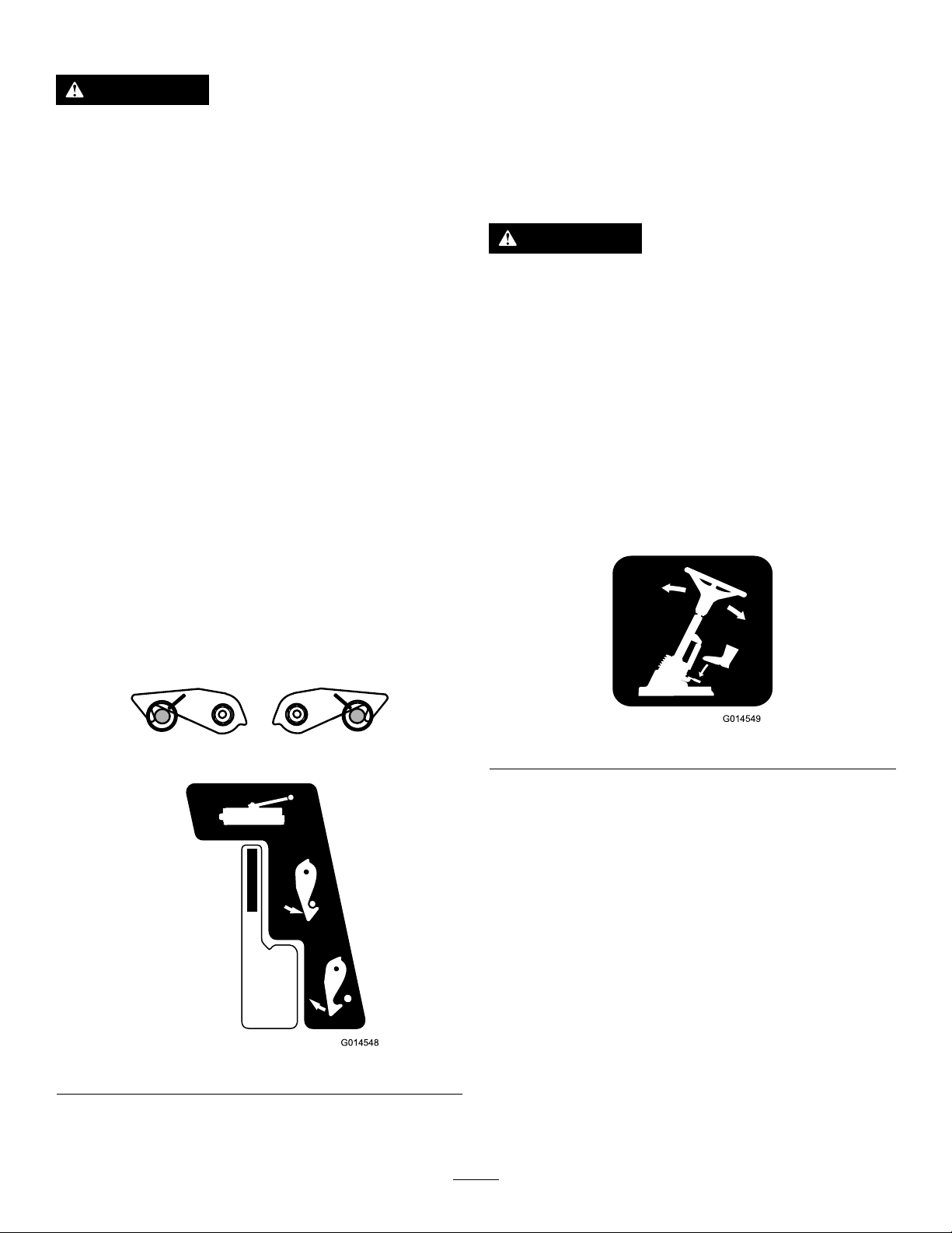
40-13–010
1.Cuttinghazardofhand
2.Cuttinghazardoffoot
70-13-072
1.Jackingpoint
70-13-077
1.Warning—shutofftheengineandremovetheignitionkey
beforereleasingoroperatingsafetylatches.
950889
1.Warning—hotsurfaces.
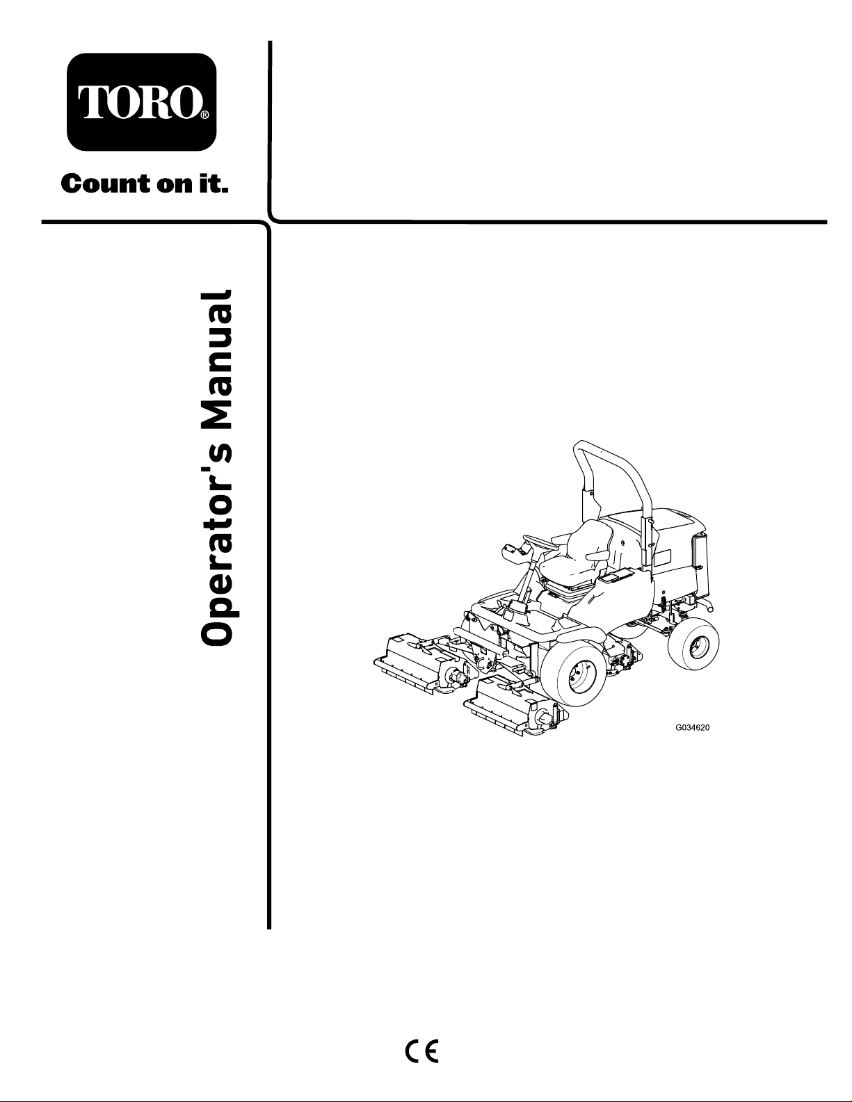
111-3277
1.Horn5.Fast
2.Cutters—lower/oat
3.Cutters—hold7.Slow
4.Cutters—raise
6.Enginespeed
111-0773
1.Warning—crushingofngers,forceappliedfromside.
111-3344
1.Ignitionswitch
8
Page 9
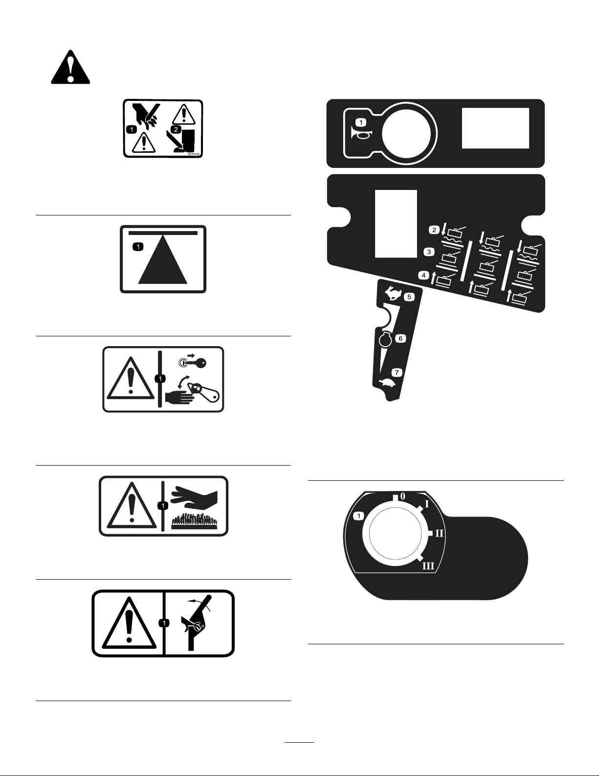
111-3562
111-3 658 Rev B
1.Presspedaltoadjuststeeringwheeltilt.
111-3658
111-3566
1.Falling,crushinghazard—ensurethattheoperator-platform
latchisengagedbeforeoperating.
111-3567
1.Pedaloperation
1.Cutterhead
2.Latch
3.Unlatch
111-3901
1.Transmissionoil—readtheOperator'sManualformore
information.
111-3902
1.Warning—cuttinghazardofhand,fan.
2.Hotsurfaces—readtheOperator'sManualformore
information.
9
Page 10
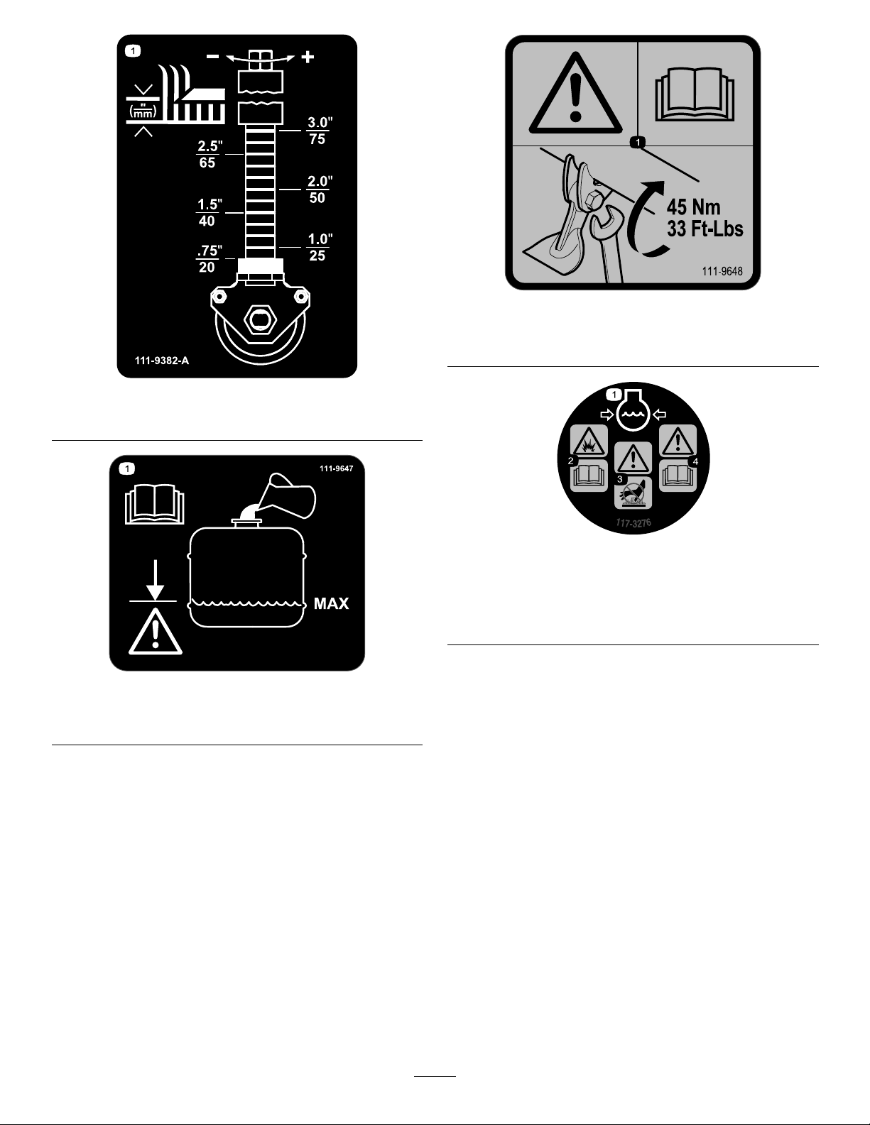
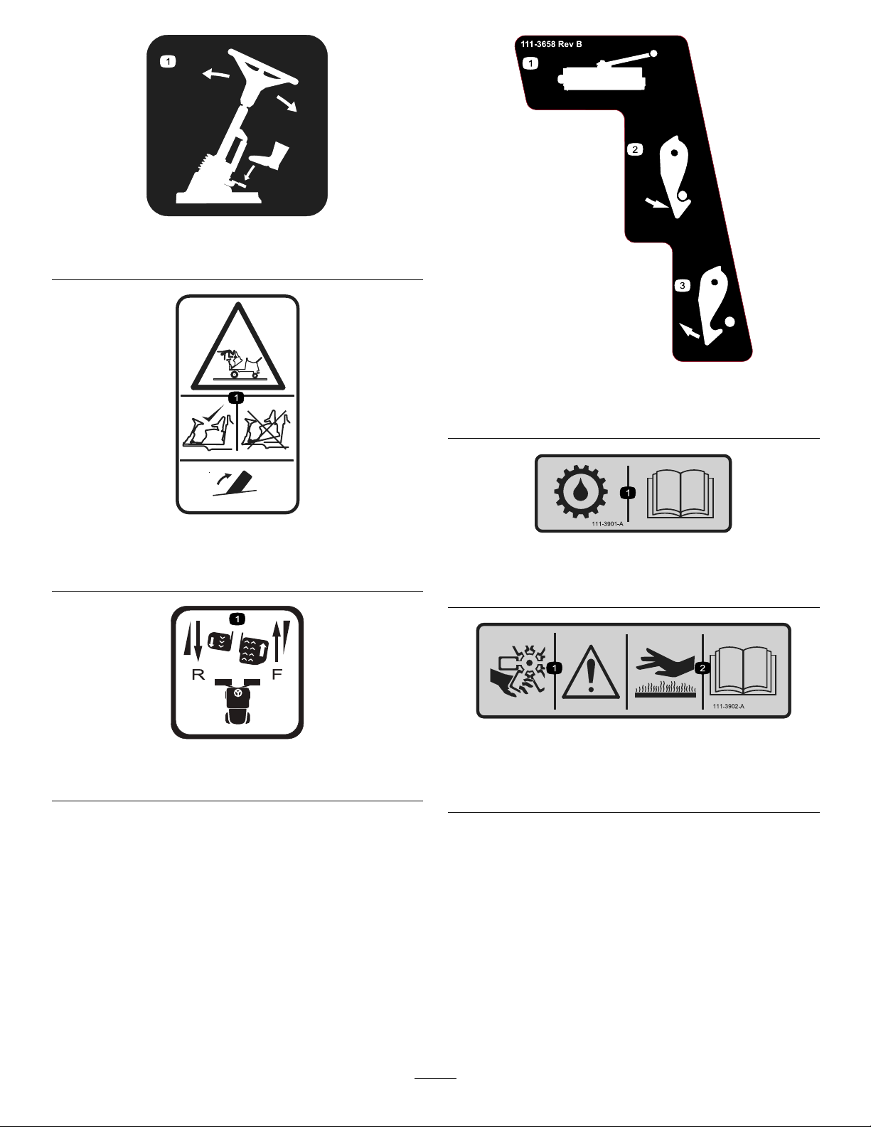
1.Height-of-cutchart
111-9648
1.Warning—readtheOperator'sManual;torquethenutsto
45N∙m(33ft-lb).
111-9382
117-3276
111-9647
1.ReadtheOperator'sManual—lltothemaximumlevel;
donotoverll.
1.Enginecoolantunder
pressure
2.Explosionhazard—read
theOperator'sManual.
3.Warning—donottouchthe
hotsurface.
4.Warning—readthe
Operator'sManual.
10
Page 11
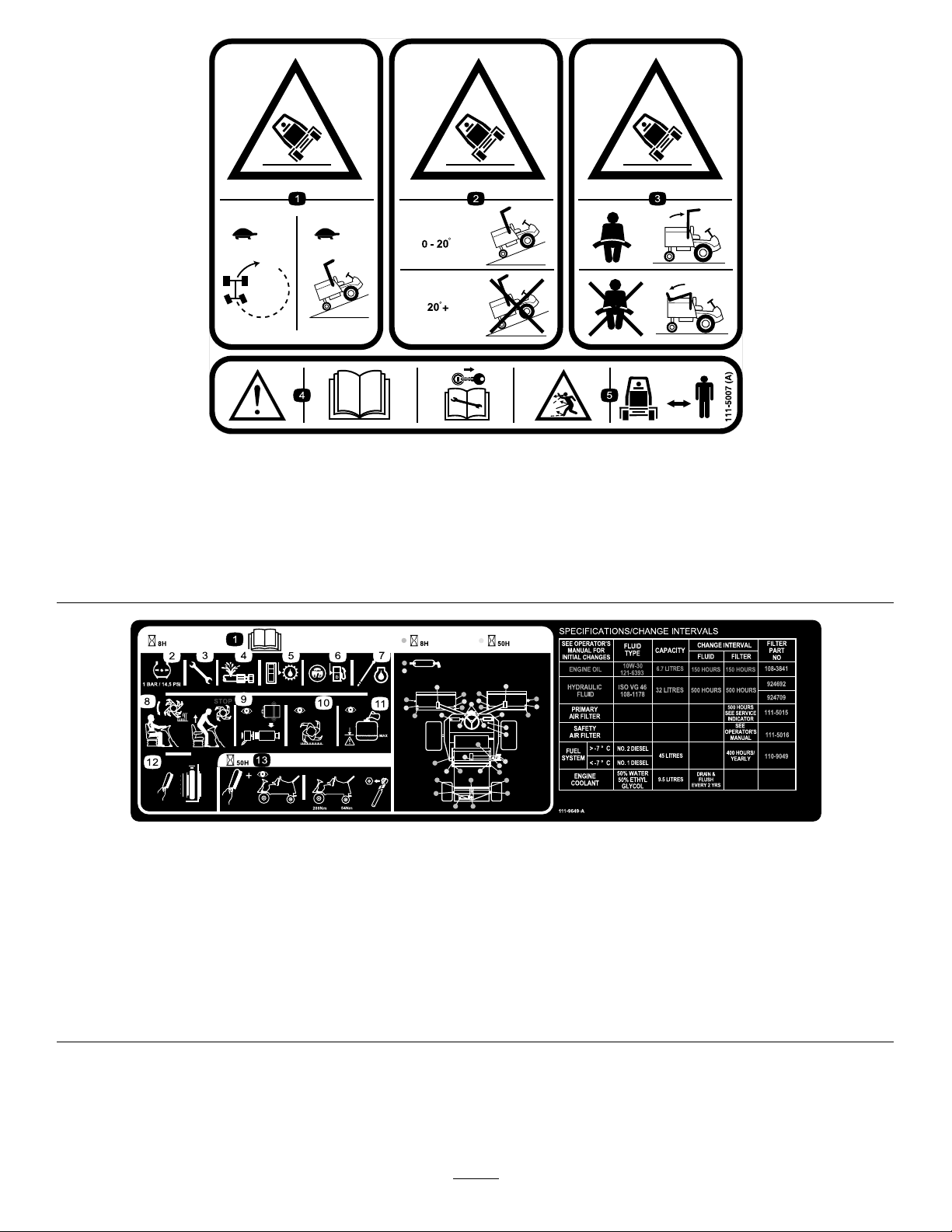
111-5007
1.Tippinghazard—slowmachinebeforeturning.
2.Tippinghazard—operateonslopeslessthan20degrees,donotoperateonslopesgreaterthan20degrees.
3.Tippinghazard—alwaysweartheseatbeltwhenarolloverprotectionsystem(ROPS)isinuse,donotwearaseatbeltwhen
theROPSbarislowered.
4.Warning—readtheOperator'sManual,removetheignitionkeybeforeperforminganymaintenance.
5.Thrownobjecthazard—keepbystandersasafedistancefromthemachine.
111-9649
1.ReadtheOperator'sManualformoreinformationonservice
andmaintenance.
2.Tirepressure—1bar(14.5psi)9.Checktheairlter.
3.Checkallfasteners.10.Inspectthebladesforwear.
4.Checkforhydraulicleaks.11.Ensurethebottleislledtothelowline.
5.Checkthetransmission-oillevel.12.Cleanthecoolingsystem.
6.Checkthefuellevel.13.Cleanthemachineandtorquethefrontwheelto200N∙m
7.Checktheoillevel.
8.Ensurethebladesstopwhenyouleavetheoperatingposition.
andtherearwheelto54N∙m.
11
Page 12
Setup
MediaandAdditionalParts
Description
Operator'sManual
Engineoperator’smanual1
PartsCatalog
DeclarationofConformity
Note:Determinetheleftandrightsidesofthemachine
fromthenormaloperatingposition.
Qty.
1
1Usethepartscatalogtolookupandorderparts.
1
Readthemanualsbeforeoperatingthemachine.
TheDeclarationofConformityservesasconrmationof
CEcompliance.
Use
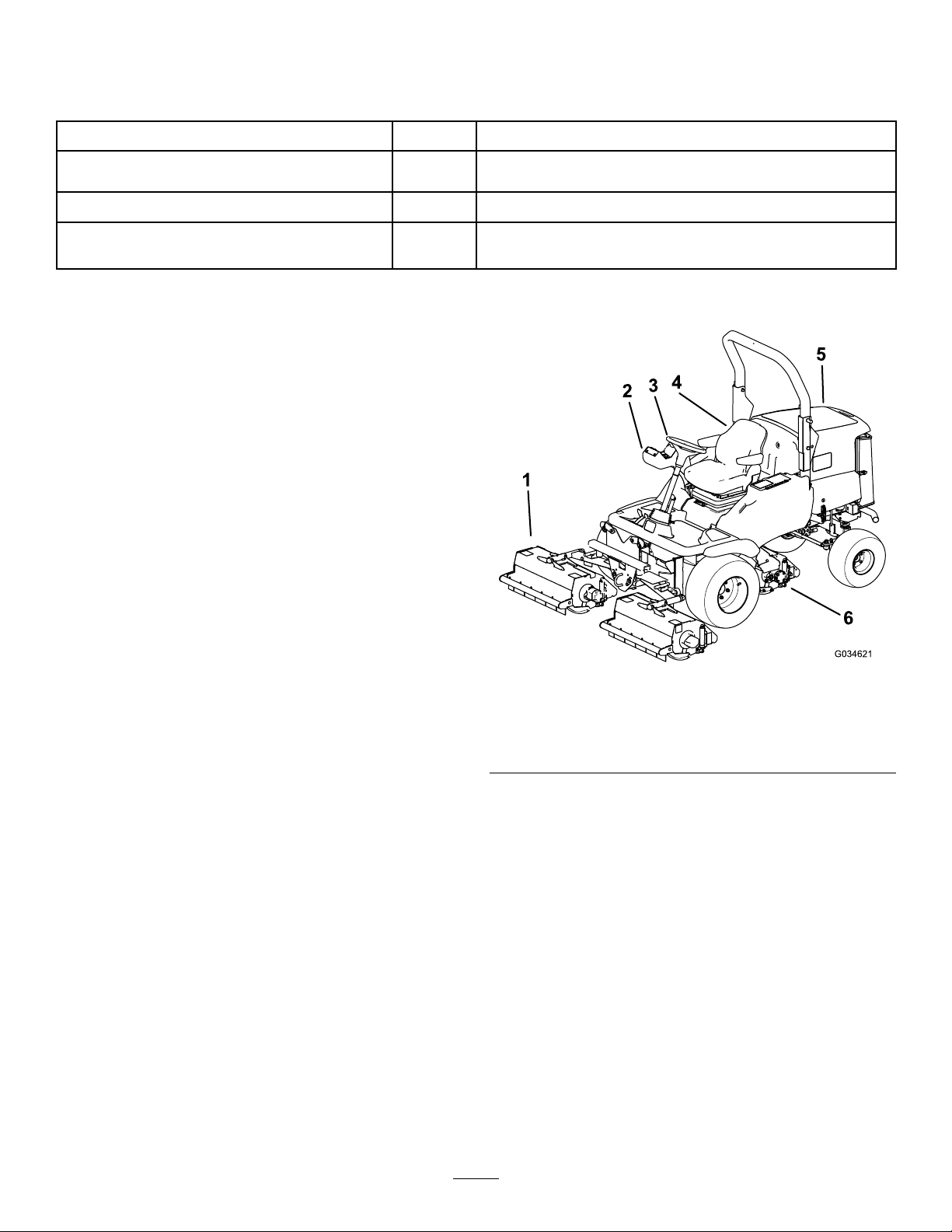
ProductOverview
1.Frontcuttingunits
2.Controlarm
3.Steeringwheel
Figure2
4.Operator'sseat
5.Enginehood
6.Rearcuttingunit
12
Page 13
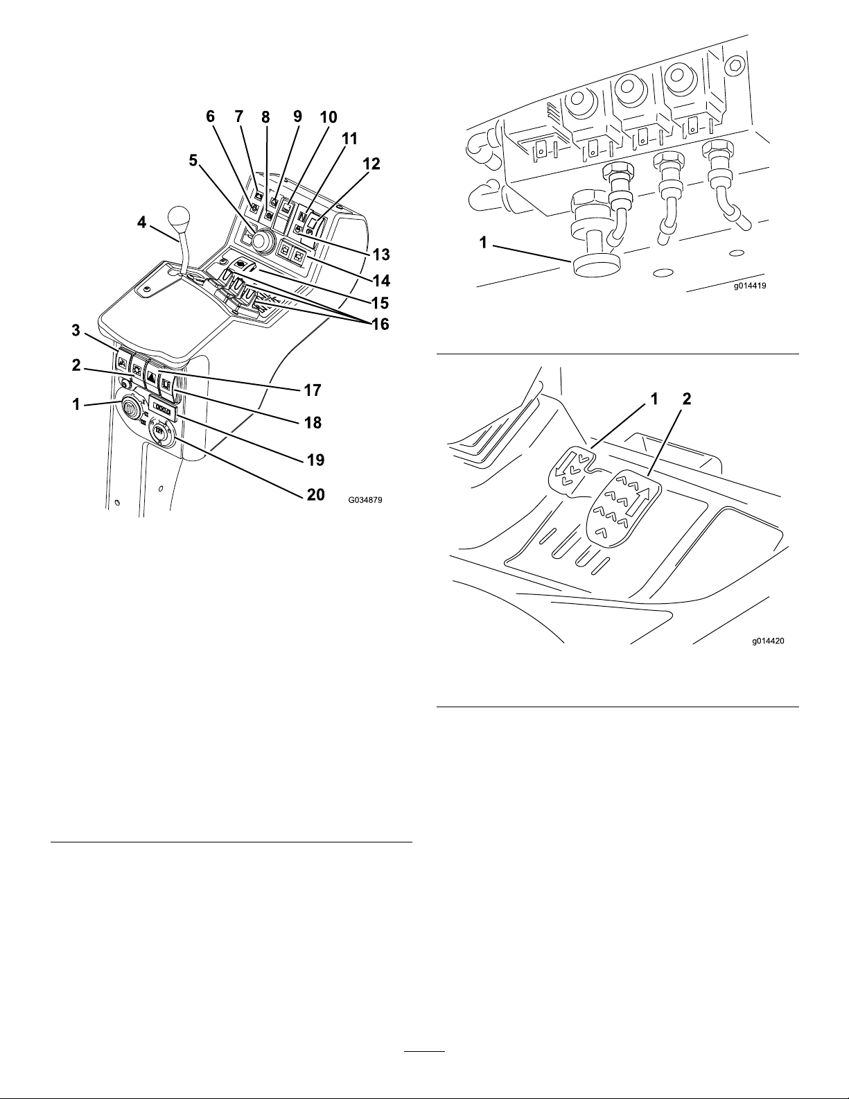
Controls
g014419
1
g014420
1 2
ControlPanelComponents
Figure4
1.Weighttransfercontrol
Figure3
1.Ignitionswitch11.Transmission-neutral
2.Lightingswitch(supplied
withlightingkit)
3.Limited-lift-in-reverse
switch
4.Throttle-controllever14.Direction-indicatorswitch
5.Hornbutton
6.Engine-oil-warninglight
7.Battery-charge-warning
light
8.Hydraulic-uid-warning
light
9.Engine-coolant-warning
light
10.Cutting-unit-driveswitch
indicator
12.Parking-brakeswitch
13.Engine-preheat-indicator
light
(suppliedwithlightingkit)
15.Differential-lockswitch
16.Lift-controlswitches
17.Hazard-warningswitch
(suppliedwithlightingkit)
18.Warning-beaconswitch
(suppliedwithbeaconkit)
19.Hourmeter
20.Auxiliary12Vsocket
Figure5
1.Reversetravelpedal2.Forwardtravelpedal
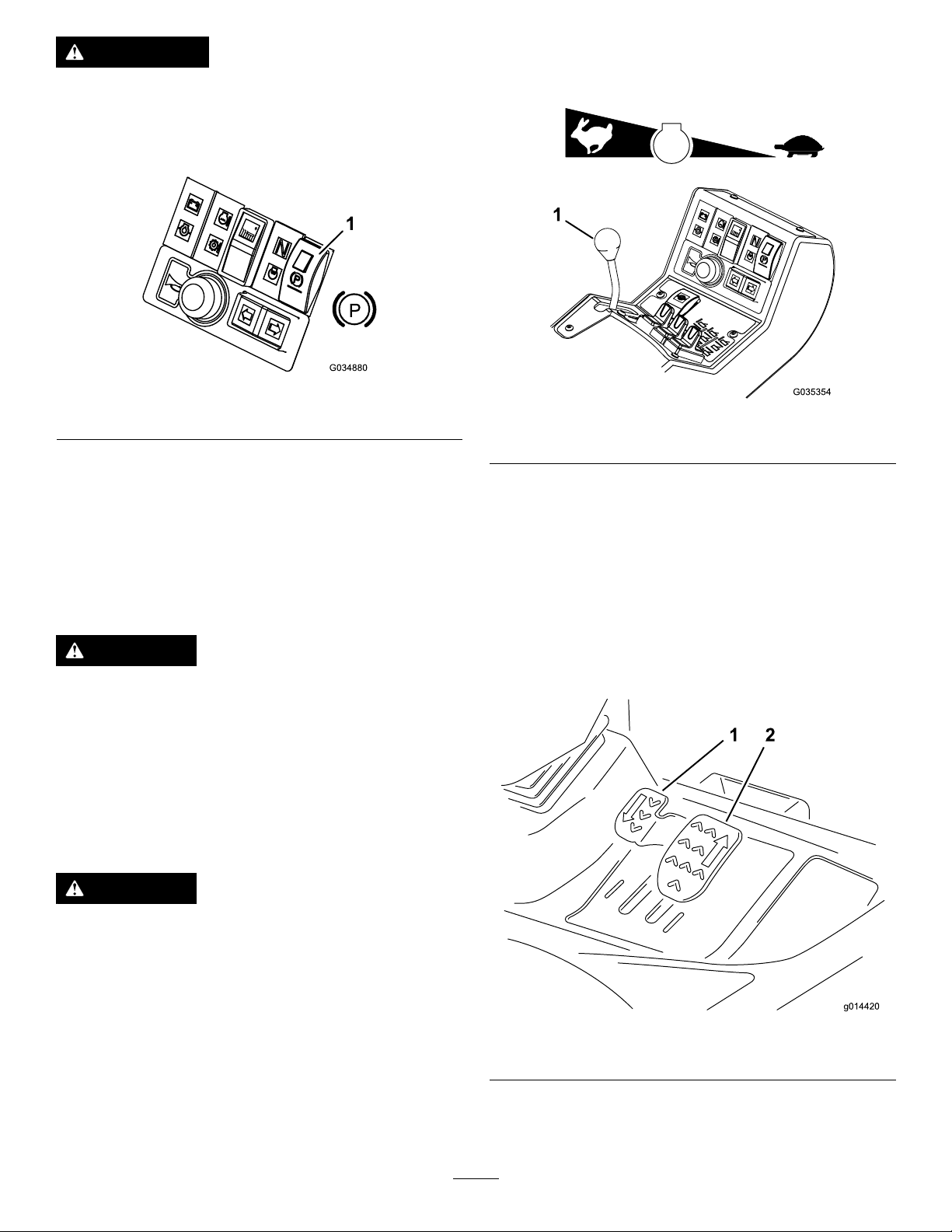
BrakingSystem
ParkingBrake
Movetheparking-brakeswitchtotheforwardpositionby
pressingthesmallerlockingbuttonandmovingtheswitch
forwardtoengagetheparkingbrake(Figure6).
Note:Donotoperatethemowerwiththeparkingbrake
engagedanddonotengagetheparkingbrakewhilethe
mowerismoving.
Thislightilluminateswhentheparkingbrakeisengagedand
theignitionkeyisturnedtopositionI.
13
Page 14
WARNING
g014420
1 2
Theparkingbrakeoperatesonthefrontwheels
onlyandthemachinecouldrolloverandmaycause
ejectionfromthemachine,paralysis,orevendeath.
Donotparkthemachineonaslope.
Figure6
Note:Theenginespeeddictatesthespeedoftheother
functions,i.e.,travel,ail-rotorrotationspeed,andcutting
unitliftspeed.
1.Parking-brakeswitch
ServiceBrake
Servicebrakingisachievedbythehydraulictransmission
system.Whentheforwardorreversetravelpedalsare
releasedortheenginespeedisreduced,servicebraking
becomeseffectiveandtravelspeedisautomaticallyreduced.
Toincreasethebrakingeffect,pushthetransmissionpedal
intotheNEUTRALposition.Servicebrakingiseffectiveon
thefrontwheelsonly.
DANGER
Theservicebrakingsystemdoesnotholdthe
moweratastandstillandcouldcausesevereinjury
ordeath.
Alwaysensurethattheparkingbrakeisengagedto
parkthemoweratastandstill.
EmergencyBrake
Intheeventofservicebrakefailure,turntheignitionoffto
bringthemowertoastandstill.
Figure7
1.Throttle-controllever
Travel
Forwardtravel:Presstheforwardtravelpedaltoincrease
forwardtravelspeed.Releasethepedaltoreducespeed
(Figure8).
Reversetravel:Pressthereversetravelpedaltoincrease
reversetravelspeed.Releasethepedaltoreducespeed
(Figure8).
Stop(Neutral):Releasetheforwardorreversetravelpedal.
DANGER
Thismachineisequippedwithanemergency
brakingsystemwhichcancauseejection,serious
injury,paralysis,orevendeath.
Usecautionwhenusingtheemergencybraking
system,remainseated,andholdontothesteering
wheel.
ThrottleControl
Operatethethrottlecontrolinaforwarddirectiontoincrease
theenginespeed.Operatethethrottlecontrolinarearward
directiontoreduceenginespeed(Figure7).
Figure8
1.Reversetravelpedal2.Forwardtravelpedal
14
Page 15
DifferentialLock
G014548
G014549
Cutting-Unit-DriveSwitch
WARNING
Theturningradiusincreaseswhenthedifferential
lockisengaged.Usingthedifferentiallockathigh
speedmayleadtolossofcontrolandcauseserious
injuryand/orpropertydamage.
Donotusethedifferentiallockathighspeed.
Usethedifferentiallocktopreventexcessivewheelspinwhen
thedrivewheelslosetraction.Thedifferentiallockoperates
inbothforwardandreverse.Youcanlockthedifferential
whilethemachineistravelingslowly.Enginepowerdemand
increaseswhenthedifferentialislocked.Preventexcessive
powerrequirementsbyusingthedifferentiallockonlyatlow
speed.
Tolockthedifferential,pressthedifferential-lockswitch.
Tounlockthedifferential,releasethedifferential-lockswitch.
Cutting-UnitsPositionControls
Usethecutting-unitspositioncontrolstoindependentlyraise
andlowerthecuttingunits;refertoControllingthePosition
oftheIndividualCuttingUnits(page28).
Toengagethecuttingunitdrive,refertoEngagingthe
CuttingUnitDrive(page29).
Note:Alwaysputthecutting-unit-driveswitchintheOFF
positionwhentravellingbetweenworkareas.
AdjustableSteeringColumn
WARNING
Thesteeringcolumnmaycauseinjuryifitisnotin
workingorder.
Checkthatthesteeringcolumnadjustermechanism
isingoodworkingorderandthat,onceadjusted
andlocked,thesteeringwheelremainssecurelyin
position.
Adjustmentofthesteeringwheelandsteeringcolumnshould
onlybecarriedoutwhenthemowerisatastandstillwith
theparkingbrakeengaged.
1.Totiltthesteeringwheel,pressthefootpedaldown.
2.Positionthesteeringtowertothemostcomfortable
positionandreleasethepedal(Figure10).
TransportLatches
AlwaysraisethecuttingunitstotheTRANSPORTposition
andsecurewiththetransportlatchesandsafetylockswhen
travellingbetweenworkareas(Figure9).
Figure10
Figure9
15
Page 16
OperatorSeat
1
G016377
1
2
G016378
WARNING
Iftheoperator-platformlatchisnotfullyengaged
beforeoperationtheseatmayfallandcrushthe
operator.
Ensurethattheoperator-platformlatchisengaged
beforeoperatingthemachine.
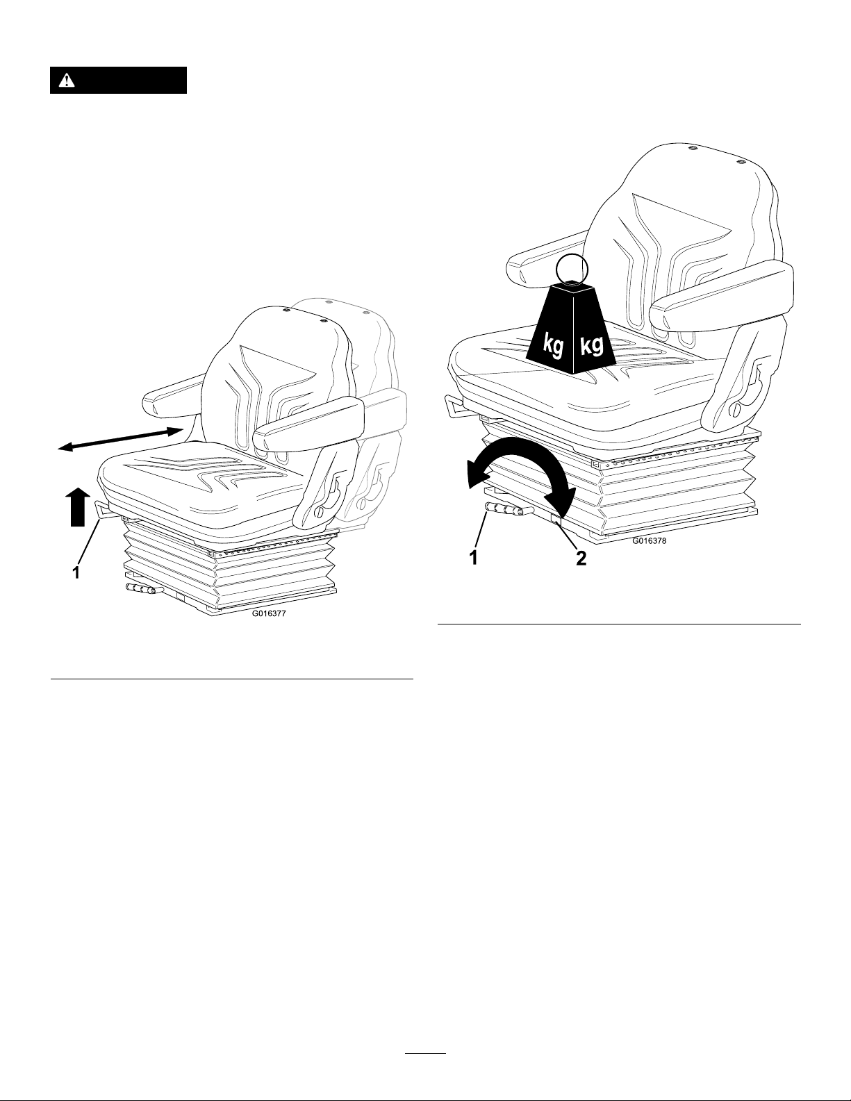
•Forward/BackwardAdjustment:Movethelever
upwardtoadjusttheforward/backwardpositionofthe
seat.Releasethelevertolocktheseatinposition(Figure
11).
•Operatorweightadjustment:Rotatethehandle
clockwisetoincreasesuspensionstiffnessand
counterclockwisetodecreasethestiffness.Thedial
indicateswhentheoptimumsuspensionadjustmenthas
beensetaccordingtooperatorweight(kg);refertoFigure
12.
Figure12
1.Lever2.Dial
Figure11
1.Lever
16
Page 17
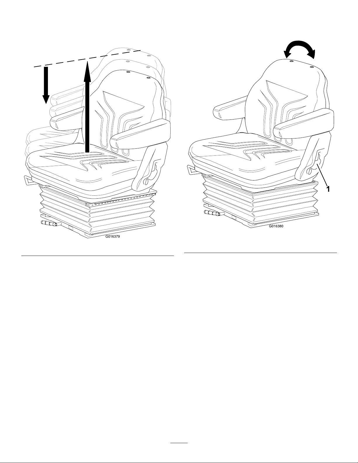
•Heightadjustment:Manuallylifttheseatfor
G016379
1
G016380
incrementalheightadjustment.Tolowertheseat,liftit
beyondthehighestsetting,thenallowittodroptothe
lowestsetting(Figure13).
•Backrestadjustment:Pullthehandleoutwardtoadjust
theseatbackrestangle.Releasethehandletolockthe
seatbackrestinposition(Figure14).
Figure13
Figure14
1.Handle
17
Page 18
WarningSystems
Battery-Charge-WarningLight
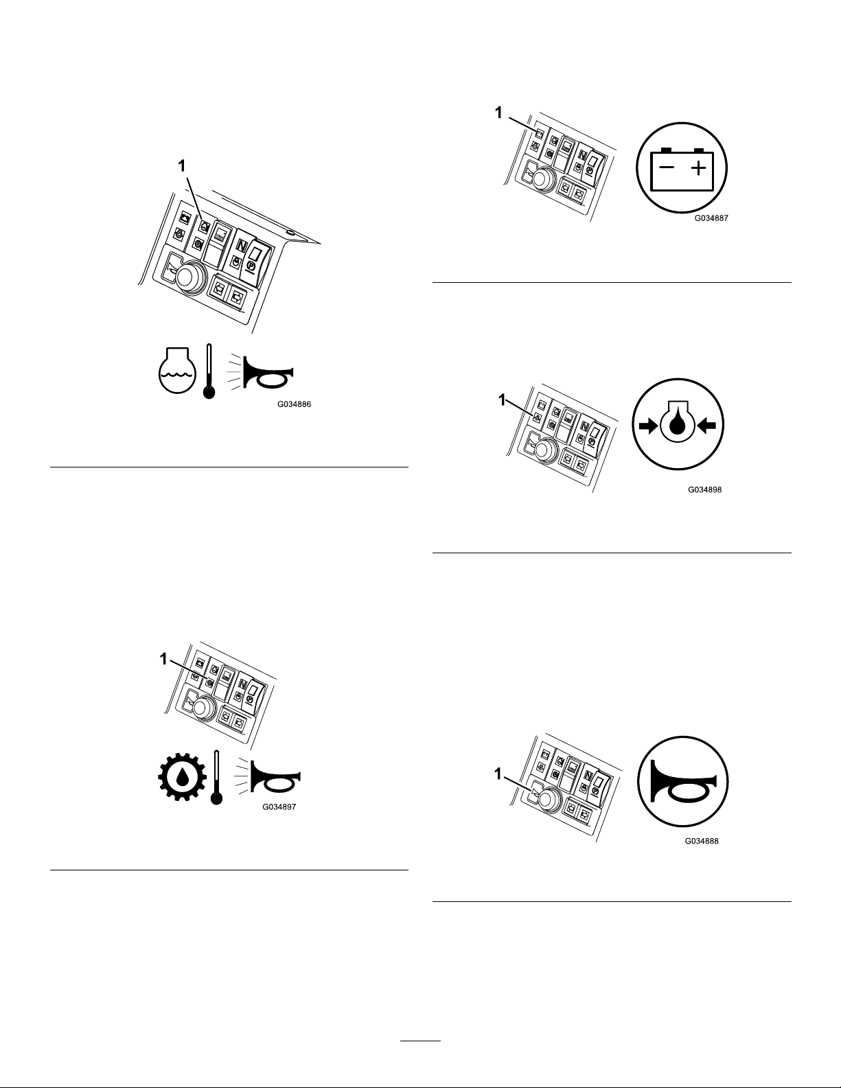
Engine-Coolant-Temperature-WarningLight
Theengine-coolant-temperature-warninglightilluminates,
thehornisactuated,andthecuttingunitsstopwhenthe
enginebecomestoohot(Figure15).
Figure15
1.Engine-coolant-temperature-warninglight
Thebattery-charge-warninglightilluminateswhenthebattery
islowofcharge(Figure17).
Figure17
1.Battery-charge-warninglight
Engine-Oil-Pressure-WarningLight
Theengine-oil-pressure-warninglightilluminateswhenthe
oilpressureistoolow(Figure18).
Note:Theailrotorsdisengagewhentheoperating
temperaturereaches115°C(239°F).
Hydraulic-Fluid-Temperature-WarningLight
Thehydraulic-uid-temperature-warninglightilluminates
whenoverheatingoccursandthehornisactuatedwhenthe
hydraulicuidinthereservoirexceeds95°C(203°F);refer
toFigure16.
Figure16
1.Hydraulic-uid-temperature-warninglight
Figure18
1.Engine-oil-pressure-warninglight
AudibleWarningHorn
Pressthehornbuttontoprovideanaudiblewarning(Figure
19).
Important:Thehornisautomaticallyactuatedwhen
anenginecoolantorhydraulic-uid-overheatcondition
occurs.Shutofftheengineimmediatelyandxthe
machinebeforestartingitagain.
Figure19
1.Horn
18
Page 19

IgnitionSwitch
G014556
1
I
II
III
G014558
FUEL
E
F
1
G014559
000.0
FuelGauge
0=Engineoff
I=Enginerun/auxiliaryon
II=Enginepreheat
III=Enginestart
WARNING
Ifyouleavethekeyintheignitionswitch,someone
couldaccidentallystarttheengineandseriously
injureyouorotherbystanders.
Lowerthecuttingunitstotheground,setthe
parkingbrake,andremovethekeyfromtheignition
switchwhenthemachineisnotinuse.
Figure20
Thefuelgaugeshowstheamountoffuelinthetank
(Figure22).
Figure22
HourMeter
Thehourmetershowsthetotalhoursthatthemachinehas
beenoperated(Figure23).
1.Ignitionswitch
Engine-Preheat-IndicatorLight
TurntheignitionkeytopositionII.Theenginepreheat
indicatorlightilluminatesandheatstheglowplugs
(Figure21).
Important:Attemptingtostartacoldenginebefore
thepreheatisusedcancauseunnecessaryweartothe
battery.
Tostartacoldengine,refertoStartingaColdEngine(page
26).
Figure21
Figure23
1.Hourmeter
Transmission-Neutral-IndicatorLight
Thislightilluminateswhenthetravel-controlpedalisinthe
NEUTRALpositionandtheignitionkeyisturnedtoposition
I(Figure24).
Note:Theparkingbrakemustbeengagedforthe
transmissionneutralindicatorlighttoilluminate.
Figure24
1.Transmission-neutral-indicatorlight
1.Engine-preheat-indicatorlight
19
Page 20

Cutting-Unit-Drive-Switch-Indicator
Light
ThislightilluminateswhenthecuttingunitdriveswitchisOn
andtheignitionkeyisturnedtopositionI(Figure25).
Toengagethecuttingunitdrive,refertoEngagingthe
CuttingUnitDrive(page29).
1.Cutting-unit-drive-switch-indicatorlight
Specications
Note:Specicationsanddesignaresubjecttochangewithoutnotice.
Figure25
Specication
TransportWidth
Widthofcut76cm(30inches)to212cm(83.5inches)
Heightofcut20mm(3/4inch)to75mm(3inches)
Length
Height
Weight
Engine
Fueltankcapacity
Transportspeed
Mowingspeed
Kubota32.8kw(44hp)at3,000rpmDIN70020
302.5cm(119.1inches)
216cm(85.0inches)withROPS
209cm(82.3inches)withcab
1,380kg(3,042lb)withROPS
1,580kg(3,483lb)withcab
LT -F3000
157.5cm(62inches)
45.7L(12USgallons)
25km/h(15.5mph)
11km/h(6.85mph)
Hydraulicsystemcapacity
Enginespeed3,000rpm
Rotorspeed3,000rpm
32L(8.5USgallons)
Attachments/Accessories
AselectionofToroapprovedattachmentsandaccessoriesisavailableforusewiththemachinetoenhanceandexpandits
capabilities.ContactyourAuthorizedServiceDealerorDistributor.
TobestprotectyourinvestmentandmaintainoptimalperformanceofyourToroequipment,countonTorogenuineparts.
Whenitcomestoreliability,Torodeliversreplacementpartsdesignedtotheexactengineeringspecicationofourequipment.
Forpeaceofmind,insistonT orogenuineparts.
20
Page 21

Operation
G009027
1
2
Note:Determinetheleftandrightsidesofthemachine
fromthenormaloperatingposition.
CAUTION
Ifyouleavethekeyintheignitionswitch,someone
couldaccidentlystarttheengineandseriously
injureyouorotherbystanders.
Parkthemachineonlevelground,lowerthecutting
unitstotheground,settheparkingbrakeand
removethekeyfromtheignitionswitchbefore
servicingormakingadjustmentstothemachine.
ThinkSafetyFirst
Carefullyreadallsafetyinstructionsandsymbolsinthe
safetysection.Knowingthisinformationcouldhelpyouor
bystandersavoidinjury.
DANGER
Operatingonwetgrassorsteepslopescancause
slidingandlossofcontrol.
•Donotoperateonslopesgreaterthan20
degrees.
•Reducespeedanduseextremecautionon
slopes.
•Donotoperatethemachinenearwater.
DANGER
Wheelsdroppingoveredgescancauserollovers,
whichmayresultinseriousinjury,death,or
drowning.
Figure26
1.Weareyeprotection.2.Wearhearingprotection.
CheckingtheEngine-OilLevel
ServiceInterval:Beforeeachuseordaily
Theengineisshippedwithoilinthecrankcase;however,the
oillevelmustbecheckedbeforeandaftertheengineisrst
started.
Crankcasecapacity:approximately6.7L(7.1USqt)with
thelter
Usehigh-qualityengineoilthatmeetsthefollowing
specications:
•APIClassicationLevelRequired:CH-4,CI-4orhigher
•Preferredoil:SAE15W -40(above0°F)
•Alternateoil:SAE10W-30or5W-30(alltemperatures)
ToroPremiumEngineoilisavailablefromyourdistributorin
either15W -40or10W-30viscosity .
Note:Thebesttimetochecktheengineoiliswhenthe
engineiscoolbeforeithasbeenstartedfortheday.Ifithas
alreadybeenrun,allowtheoiltodrainbackdowntothe
sumpforatleast10minutesbeforechecking.
1.Parkthemachineonalevelsurface,shutofftheengine,
settheparkingbrakeandremovethekeyfromthe
ignitionswitch.
2.Openthehood.
3.Removethedipstick,wipeitclean,andinstallit
(Figure27).
Donotoperatethemachineneardrop-offs.
CAUTION
Thismachineproducessoundlevelsthatcancause
hearinglossthroughextendedperiodsofexposure.
Wearhearingprotectionwhenoperatingthis
machine.
Theuseofprotectiveequipmentforeyes,ears,hands,feet,
andheadisrecommended.
1.Dipstick
4.Removedipstickandcheckoillevelondipstick.
21
Figure27
Page 22

Note:TheoillevelshouldbeuptotheFULLmark.
1
g025068
5.IftheoillevelisbelowtheFULLmark,removethell
cap(Figure28)andaddoiluntillevelreachestheFULL
markondipstick.
Important:Donotoverll.
Figure28
CheckingtheCoolingSystem
ServiceInterval:Beforeeachuseordaily
CAUTION
Iftheenginehasbeenrunning,thepressurized,hot
coolantcanescapeandcauseburns.
•Donotopentheradiatorcapwhentheengine
isrunning.
•Usearagwhenopeningtheradiatorcap,and
openthecapslowlytoallowsteamtoescape.
Thecoolingsystemislledwitha50/50solutionofwater
andpermanentethyleneglycolantifreeze.
1.Cleandebrisoffthescreen,oilcooler,andfrontof
theradiatordailyandmoreoftenifconditionsare
extremelydustyanddirty.RefertoRemovingDebris
fromtheCoolingSystem(page45).
2.Checkthelevelofthecoolantintheexpansiontank
(Figure29).
Note:Whencold,thecoolantlevelshouldbeatthe
lowermarkonthesideofthetank.
1.Oil-llcap
6.Installtheoil-llcapandclosethehood.
Figure29
1.Expansiontank
3.Ifthecoolantlevelislow,removetheexpansion-tank
capandreplenishthesystem.
Note:Donotoverll.
4.Installtheexpansion-tankcap.
22
Page 23

AddingFuel
DANGER
ServiceInterval:Beforeeachuseordaily
Useonlyclean,freshdieselfuelwithlow(<50ppm)or
ultra-low(<15ppm)sulfurcontent.Theminimumcetane
ratingshouldbe40.Purchasefuelinquantitiesthatcanbe
usedwithin180daystoensurefuelfreshness.
Fueltankcapacity:45.7L(12USgallons)
Usesummergradedieselfuel(No.2-D)attemperatures
above-7°C(20°F)andwintergrade(No.1-DorNo.
1-D/2-Dblend)belowthattemperature.Useofwintergrade
fuelatlowertemperaturesprovideslowerashpointand
coldowcharacteristicswhicheasesstartingandreducesfuel
lterplugging.
Useofsummergradefuelabove-7°C(20°F)contributes
towardlongerfuelpumplifeandincreasedpowercompared
towintergradefuel.
Important:Donotusekeroseneorgasolineinstead
ofdieselfuel.Failuretoobservethiscautiondamages
theengine.
WARNING
Fuelisharmfulorfatalifswallowed.Long-term
exposuretovaporscancauseseriousinjuryand
illness.
•Avoidprolongedbreathingofvapors.
•Keepfaceawayfromnozzleandfueltankor
conditioneropening.
•Keepfuelawayfromeyesandskin.
Incertainconditionsduringfueling,static
electricitycanbereleased,causingasparkwhich
canignitethefuelvapors.Areorexplosionfrom
fuelcanburnyouandothersandcandamage
property.
•Alwaysplacefuelcontainersonthegroundaway
fromyourvehiclebeforelling.
•Donotllfuelcontainersinsideavehicleoron
atruckortrailerbedbecauseinteriorcarpets
orplastictruck-bedlinersmayinsulatethe
containerandslowthelossofanystaticcharge.
•Whenpractical,removeequipmentfromthe
truckortrailerandfueltheequipmentwiththe
wheelsontheground.
Ifthisisnotpossible,thenfuelsuchequipment
onatruckortrailerfromaportablecontainer,
ratherthanfromafuel-dispensernozzle.
•Ifafuel-dispensernozzlemustbeused,keepthe
nozzleincontactwiththerimofthefueltank
orcontaineropeningatalltimesuntilfuelingis
complete.
1.Parkthemachineonalevelsurface.
2.Usingacleanrag,cleantheareaaroundthefuel-tank
cap.
3.Removethecapfromthefueltank.
4.Fillthetankuntilthelevelistothebottomoftheller
neckwithdieselfuel.
DANGER
Incertainconditions,fuelisextremelyammable
andhighlyexplosive.Areorexplosionfromfuel
canburnyouandothersandcandamageproperty.
•Fillthefueltankoutdoors,inanopenarea,when
theengineiscold.Wipeupanyfuelthatspills.
•Neverllthefueltankinsideanenclosedtrailer.
•Neversmokewhenhandlingfuel,andstayaway
fromanopenameorwherefuelfumesmaybe
ignitedbyaspark.
•Storefuelinanapprovedcontainerandkeepit
outofthereachofchildren.Neverbuymore
thana180-daysupplyoffuel.
•Donotoperatemachinewithoutentireexhaust
systeminplaceandinproperworkingcondition.
5.Installthefuel-tankcaptightlyafterllingthetank.
Note:Ifpossible,llthefueltankaftereachuse.This
minimizespossiblebuildupofcondensationinsidethe
fueltank.
CheckingtheHydraulicFluid
ServiceInterval:Beforeeachuseordaily
Thereservoirislledatthefactorywithapproximately32L
(8.5USgallons)ofhigh-qualityhydraulicuid.Thebesttime
tocheckthehydraulicuidiswhenitiscold.
Therecommendedreplacementuidis:
ToroPremiumAllSeasonHydraulicFluid:Available
in19L(5USgallon)containersor208L(55USgallon)
drums—seethePartsCatalogoryourT orodistributorforpart
numbers.
Alternativeuids:IftheTorouidisnotavailable,other
uidsmaybeusedprovidedthattheymeetallofthefollowing
materialpropertiesandindustryspecications.Checkwith
youroilsuppliertoidentifyasatisfactoryproduct.
23
Page 24

Note:T orodoesnotassumeresponsibilityfordamage
2
1
G014570
3
causedbyimpropersubstitutions,souseonlyproducts
fromreputablemanufacturerswhostandbehindtheir
recommendation.
HighViscosityIndex/LowPourPointAntiwearHydraulic
Fluid,ISOVG46Multigrade
MaterialProperties:
Viscosity,ASTMD445cSt@40°C(104°F)
Viscosityindex,ASTM
D2270
Pourpoint,ASTMD97-36.7°Cto-45°C(-34°Fto
FZG,failstage
Watercontent(newuid)500ppm(maximum)
IndustrySpecications:
VickersI-286-S,VickersM-2950-S,DenisonHF-0,
Vickers35VQ25(EatonATS373-C)
44to48
cSt@100°C(212°F)
7.9to9.1
140orhigher(high
viscosityindexindicatesa
multiweightuid)
-49°F)
11orbetter
Figure30
1.Hydraulic-tankcap
2.Fluidtank
3.Sight-levelgauge
Theproperhydraulicuidsmustbespeciedfor
mobilemachinery(asopposedtoindustrialplantusage),
multiweight-type,withZnDTPorZDDPantiwearadditive
package(notanashless-typeuid).
Important:Manyhydraulicuidsarealmostcolorless,
makingitdifculttospotleaks.Areddyeadditivefor
thehydraulicsystemoilisavailablein20ml(2/3oz)
bottles.Onebottleissufcientfor15to22L(4to6US
gallons)ofhydraulicuid.Orderpart44-2500fromyour
AuthorizedToroDistributor.
Synthetic,BiodegradableHydraulicFluid:Availablein
19L(5USgallon)containersor208L(55USgallon)
drums—seethe
P ar ts Catalo g
oryourTorodistributor
forpartnumbers.
Thishigh-quality,synthetic,biodegradableuidhasbeen
testedandfoundcompatibleforthisToromodel.Other
brandsofsyntheticuidmayhavesealcompatibilityproblems
andTorocannotassumeresponsibilityforunauthorized
substitutions.
Note:Thissyntheticuidisnotcompatiblewiththe
ToroBiodegradableFluidpreviouslysold.SeeyourToro
Distributorformoreinformation.
Alternativeuids:
•MobilEALEnvirosynH46(US)
•MobilEALHydraulicOil46(international)
4.Removethecapandllthetanktotheuppermark
onthesight-levelgauge.
Important:Donotoverllthetank.
5.Installthecapontothetank.
CheckingtheTirePressure
Checktheairpressureinthefrontandreartires.Refertothe
chartbelowforthecorrectpressure.
Important:Maintaincorrecttirepressureinalltiresto
ensurecorrectcontactwiththeturf.
Recommendedtirepressureis1bar(14.5psi)forgeneralall
arounduse.Tirepressurescanbeadjustedaccordingtothe
followingtabledependingonoperatingconditions.
RecommendedTirePressures TiresTireType
FrontAxle26x
12.0-12
BKTturf
pattern
RearAxle20x10.0-
8BKTturf
pattern
Conditions
0.7bar(10
0.7bar(10
Turf
psi)
psi)
Road
Conditions
1.4bar(20
psi)
1.4bar(20
psi)
Maximum
Pressure
1.7bar(25
psi)
1.7bar(25
psi)
1.Positionthemachineonalevelsurface,lowerthe
cuttingunits,andshutofftheengine.
2.Checkthesight-levelgaugeonthesideofthetank.
Note:Thelevelneedstobeattheuppermark.
3.Ifadditionalhydraulicuidisneeded,cleanthearea
aroundthellerneckandthecapofthehydraulictank
CheckingtheTorqueofthe Wheel-LugNuts
ServiceInterval:Beforeeachuseordaily
Torquethewheel-lugnutsto200N∙m(148ft-lb)forthefront
axle,and54N∙m(40ft-lb)fortherearaxle.
(Figure30)andremovethecap.
24
Page 25

WARNING
G014422
Understandingthe
Failuretomaintainpropertorqueofthewheelnuts
couldresultinpersonalinjury.
Ensurethatthewheelnutsaretorquedproperly.
UsingtheOperatorPlatform LatchingMechanism
Donotoperatethemowerwithoutrstcheckingthatthe
operatorplatformlatchingmechanismisfullyengagedand
ingoodworkingorder.
ReleasingthePlatform
1.Movethelocking-latchhandletowardthefrontofthe
moweruntilthelatchhooksclearthelockingbar.
2.Raisetheplatform.
Note:Thegasspringprovidesassistance.
SecuringthePlatform
1.Lowertheplatformcarefully .
Note:Thegasspringprovidesassistance.
Operator-PresenceControls
Note:Theenginestopsiftheoperatorleavestheseat
withoutengagingtheparkingbrake.
EngineStartLockout:Theenginecanonlybestarted
whentheforward/reversetravelpedalisintheNEUTRAL
position,thecuttingunitdriveswitchisintheOFFposition
andtheparkingbrakeisengaged.Whenthesecircumstances
aresatised,switchesareactivatedpermittingtheengineto
bestarted.
EngineRunInterlock:Oncetheengineisstartedthe
operatormustbeseatedbeforetheparkingbrakeisreleased
fortheenginetocontinuetorun.
FlailRotorDriveLockout:Thedrivetotheailrotorsis
onlypossiblewhentheoperatorisseated.Iftheoperator
raisesofftheseatforaperiodofmorethan1second,aswitch
isactivatedandthedrivetotheailrotorsisautomatically
disengaged.Toengagedrivetotheailrotors,theoperator
mustreturntotheseat,thenoperatethecuttingunitdrive
switchtotheOFFpositionbeforemovingitbacktotheON
position.Iftheoperatorrisesofftheseatforabriefmoment
duringnormalwork,drivetotheailrotorsisnotaffected.
Theenginecanonlybestartedwiththecuttingunitdrive
switchintheOFFposition.
2.Movethelocking-latchhandletowardthefrontofthe
mowerastheplatformnearsthefullyloweredposition.
Note:Thisensuresthatthelatchhooksclearthe
lockingbar.
3.Fullylowertheplatformandmovethelockinghandle
towardtherearofthemoweruntilthelatchhooksfully
engagethelockingbar.
WARNING
Operatingthemachinewhentheoperator-presence
controlsaremalfunctionsisdangerousandcanlead
toaccidentscausingpersonalinjury.
Alwaysreplacedamagedorwornpartsandcheck
thattheoperator-presencecontrolsarefunctioning
correctlybeforeoperatingthemachine.
CAUTION
Ifsafety-interlockswitchesaredisconnectedor
damagedthemachinecouldoperateunexpectedly
causingpersonalinjury.
•Donottamperwiththeinterlockswitches.
•Checktheoperationoftheinterlockswitches
dailyandreplaceanydamagedswitchesbefore
operatingthemachine.
StartingandShuttingOffthe
Figure31
Engine
Important:Y oumustbleedthefuelsystembefore
startingtheengineifyouarestartingtheengineforthe
rsttime,theenginehasshutoffduetolackoffuel,or
youhaveperformedmaintenanceonthefuelsystem;
refertoBleedingtheFuelSystem(page41).
25
Page 26

WARNING
G014563
Operatingthemachineinanunsafemannercould
resultinpersonalinjury.
Beforestartingtheengine,ensurethatthefollowing
conditionsaremet:
•YouhavereadandunderstoodSafeOperating
Practices(page4).
•Theareaisclearofbystanders.
•Thecutting-unitdriveisdisengaged.
•Theparkingbrakeisset.
•Thetravel-controlpedalsareintheNEUTRAL
position.
StartingaWarmEngine
1.Sitontheseat,keepyourfootoffthetractionpedalso
thatitisintheNEUTRALposition,engagetheparking
brakeandsetthethrottletothe70percentfullthrottle.
2.TurntheignitionkeytotheignitiononpositionIand
checkthattheengineoilpressureandbatterycharge
warninglightsilluminate.
3.TurntheignitionkeytothestartpositionIIIandhold
tocranktheengine.
Note:Cranktheenginefornolongerthan15seconds.
ReleasetheignitionkeybacktopositionIwhenthe
enginestarts.
4.Runtheengineatlowidlespeeduntilitwarmsup.
Important:Thismachineisttedwithanenginestart
lockout;refertoUnderstandingtheOperator-Presence
Controls(page25).
StartingaColdEngine
1.Sitontheseat,keepyourfootoffthetractionpedals
sothatitisinNEUTRAL,engagetheparkingbrakeand
setthethrottletothe70percentfullthrottleposition.
2.TurntheignitionkeytotheignitiononpositionIand
checkthattheengineoilpressureandbatterycharge
warninglightsilluminate.
3.TurntheignitionkeytothepreheatpositionIIsothat
thepreheat-indicatorlightison.Holditfor5seconds
toheattheglowplugs.
4.Afterpreheatingtheglowplugs,turnkeytothestart
positionIIIandholdtocranktheengine.
Note:Cranktheenginefornolongerthan15seconds.
ReleasetheignitionkeybacktopositionIwhenthe
enginestarts.
5.Runtheengineatlowidlespeeduntilitwarmsup.
StoppingtheEngine
1.MoveallcontrolstoNeutral,settheparkingbrake,
movethethrottletothelowidlepositionandallowthe
enginetoreachlowidlespeed.
Important:Allowtheenginetoidlefor5
minutesbeforeshuttingitoffafterafullload
operation.Failuretodosomayleadtotroubleon
aturbo-chargedengine.
2.Lettheengineidlefor5minutes.
3.Turntheignitionkeytoposition0.
Note:Iftheenginefailstostopwhentheignition
keyisturnedto0,pushtheengine-stopleverforward
(Figure33).
WARNING
Touchingmovingobjectsmayresultin
pinchingandtouchinghotenginepartsmay
resultinburningoftheskin.
Keepyourhandsclearofmovingobjectsand
hotenginepartswhiletheengineisrunning.
Figure32
1.Engine-preheat-indicatorlight
WARNING
Operatingthemachinewithamalfunctioncould
causeseriousdamage.
Ifawarninglightcomesonduringoperation,stop
themachineimmediatelyandcorrecttheproblem
beforecontinuingoperation.
Figure33
26
Page 27

FlailCuttingUnitGeneral Information
Itisimportanttokeeptheailbladessharpandingood
conditiontoensuregoodcuttingperformance,minimum
powerconsumption,andagoodqualityofcut.
Theailheadisanecutailandshouldonlybeusedfor
maintaininggrass.Itsrecommendedthatamaximumof1/3
ofthetotalgrasslengthisremovedwhencut.
Thescraperwiresarettedtoremovedebrisfromthe
roller,indryconditionsthesemaynotberequiredandits
recommendedtheyareremoved.Indampwetconditions
ensurethatscraperwiresdonotgetpluggedwithdebris.
Thecuttingunitoatsandcanpivotlaterallytofollowground
contours.
Thecuttingunitsaredesignedtobeoperatedatfullengine
rpm.Forwardspeedshouldbeadjusteddependingongrass
conditionsandtonotoverloadthepowerunitsortheheads.
Thelowertheforwardspeedthehigherthequalityofcut
andaftercutappearance.
AdjustingtheHeightofCut
Note:Theheightofcutisgaugedbytherearroller.Blade
wear,worncuttingunitpivots,bent/damagedcuttingunit
pins,andbent/damagedarmscanaffecttheheight-of-cut
setting.
1.Turntheadjusting-nutassemblyonbothendsclockwise
todecreasetheheightofcutorcounter-clockwiseto
increasetheheightofcut(Figure34).
Figure35
1.Indicatorrings
Note:RefertoFigure36fortheheight-of-cutsettings.
Figure36
1.75mm(3.0inches)4.40mm(1.5inches)
2.65mm(2.5inches)5.25mm(1.0inches)
3.50mm(2.0inches)6.20mm(0.75inches)
Figure34
1.Heightofcut
Important:Donotattempttounlockthenut
assemblies.
2.Ensurethatallcuttingunitsaresetatthesameheight
ofcutbyreferringtotheindicatorrings(Figure35).
2.Adjusting-nutassembly
27
Page 28

ControllingthePositionofthe
UsingtheCuttingUnit
IndividualCuttingUnits
Thecuttingunitsmayberaisedorloweredindependently
usingthebankof3lift-controlswitches.
1.Tolowerthecuttingunits,operatethelift-control
switchesinadownwarddirectionandrelease.
Note:Thecutting-unit-driveswitchmustbeontodo
this,theailrotordriveengageswhenthecuttingunits
areapproximately150mm(6inches)aboveground
level.Thecuttingunitsarenowin‘oat’modeand
followthegroundcontours.
Auto-LimitedLiftinReverse
Toactivate,presstheauto-limited-liftswitchtotheON
position(Figure38).
Todeactivate,presstheauto-limited-liftswitchtotheOFF
position(Figure38).
Manuallimitedliftusingthe3lift-controlswitchesisalways
availableregardlessofthepositionoftheautoswitch.
Figure37
1.Lift-controlswitches
2.Toraisethecuttingunits,operatethelift-control
switchesinanupwarddirectionandholdinposition
3.Ifthecutting-unit-driveswitchisintheONposition
theailrotordrivedisengages.
3.Releasethelift-controlswitcheswhenthecuttingunits
areattherequiredheight.
Note:Thecontrolswitchesautomaticallyreturnto
position2(NEUTRAL)andthearmsarehydraulically
lockedintoposition.
Toraisethecuttingunitstothelimitedliftposition:
momentarilyoperatetheswitchesinanupwarddirection.
Theailrotordrivedisengagesimmediatelyandthecutting
unitsstopraising,approximately150mm(6inches)above
groundlevel.
Thisoperateswiththecuttingunitsloweredandrotating.
Autolimitedliftinreversecausesthecuttingunitstorise
automaticallytothelimitedliftpositionwhenreversing.They
returntotheoatingpositionwhenreturningtoforward
travel.Theailrotorscontinuetorotateduringthisoperation.
Figure38
28
Page 29

EngagingtheCuttingUnit
g014435
1
2
Drive
Figure39
1.On2.Off
Thecuttingunitdrivecanbeengagedonlywhenthe
operatorisseatedcorrectly,refertoCheckingthe
Operator-Presence-SeatSwitch(page47).
Cuttingunitdriveengagement:Pressthetopofthe
cutting-unit-driveswitchtotheonposition(Figure39).
Allcuttingunitdrivesdisengagement:Settheswitchto
theoffposition(Figure39).
Tolowerthecuttingunits:Thecuttingunitdriveswitch
mustbesettotheonposition.Operatethelift-control
switch(s)inadownwarddirection.Themachinedriveswhen
thecuttingunitsareapproximately150mm(6inches)above
groundlevel.
Using Weight-Transfer/Traction Assistance
Avariablehydraulicweighttransfersystemisprovidedfor
improvingtiregripwiththegrasssurface—tractionassistance.
Hydraulicpressureinthecuttingunitsliftsystemprovidesa
liftingforcewhichreducestheweightofthecuttingunits
onthegroundandtransferstheweightasadownwardforce
ontothetiresofthemachine.Thisactionisknownasweight
transfer.
Toengageweighttransfer:Theamountofweighttransfer
canbevariedtosuitoperatingconditionsbyrotatingthe
weight-transferhandwheel(Figure40)asfollows:
Figure40
1.Lockwheel
2.Weight-transferhand
wheel
FoldingtheROPS
YoucanfoldtheROPSframedowntoallowaccessintoareas
ofrestrictedheight.
WARNING
ThemachinedoesnothaveaRolloverProtection
SystemwhentheROPSisfoldeddownandshould
notbeconsideredasRolloverProtectionSystem.
DonotwearaseatbeltwhentheROPSislowered.
1.Parkthemachineonalevelsurface,engagetheparking
brake,andshutofftheengine.
2.Supporttheweightoftheupperframewhileremoving
theR-clipsandpinsfromthepivotbrackets(Figure41).
3.Carefullylowertheframedownwardsuntilitrestson
thestops.
4.Insertthepinsinthelowerholesandsecurewith
theR-clipstosupporttheupperframeinitslowered
position.
5.Toraisetheframe,followtheseinstructionsinreverse
order.
1.Releasethevalvelocknut1/2turncounterclockwise
andhold(Figure40).
2.Rotatethevalvehandwheel(Figure40)
counterclockwisetoreduceweighttransferor
clockwisetoincreaseweighttransfer.
3.Tightenthenut.
Note:Therecommendedsettingistoincreaseweight
transferuntilheadsstarttolift,thenbackoff1/2turn,and
lock.
29
Page 30

Figure41
3
1 2
G0144447
Important:Therollbarisanintegralandeffective
safetydevice.Keeptherollbarintheraisedposition
whenoperatingthemower.Lowertherollbar
temporarilyonlywhenabsolutelynecessary.
LocatingtheJackingPoints
Note:Usejackstandstosupportthemachinewhenrequired.
WARNING
Mechanicalorhydraulicjacksmayfailtosupport
themachineandcauseseriousinjury.
Usejackstandswhensupportingthemachine.
•Front—underthefrontarmmount
•Rear—axletubeontherearaxle
1.Upperframe
2.PinsandR-clips
3.Lowerholes
WARNING
TheROPSprotectionsystemmaynotbeeffectiveif
theROPSretainingboltassembliesareloosewhich
maycauseseriousinjuryorevendeathintheevent
ofarollover.
Whenintheraisedposition,bothretainingbolt
assembliesmustbeinstalledandfullytightenedto
ensurefullROPSprotection.
WARNING
WhenloweringandraisingtheROPSframe,ngers
maygetpinchedbetweenthemachineandthe
ROPS.
UsecautionwhenloweringandraisingtheROPS
toprevententrapmentofngersbetweenxedpart
andpivotpartofthestructure.
•Keepallnuts,bolts,andscrewscorrectlytorquedensure
thattheequipmentisinsafeworkingcondition.
•Replacewornordamagedpartsforsafety.
•Ensurethattheseatbeltandmountingsareinsafe
workingorder.
•Weartheseatbeltwhentherollbarisraisedandnoseat
beltwhentherollbarislowered.
Figure42
1.Frontleftliftingpoint3.Rearliftingpoint
2.Frontrightliftingpoint
HaulingtheMachine
•Usecarewhenloadingorunloadingthemachineintoa
traileroratruck.
•Usefull-widthrampsforloadingthemachineintoa
traileroratruck.
•Tiethemachinedownsecurelyusingstraps,chains,cable,
orropes.Bothfrontandrearstrapsshouldbedirected
downandoutwardfromthemachine.
30
Page 31

TowingtheMachine
g014448
1
1 2 3
G014449
1
G014450
Ensurethatthetowingvehiclespecicationissuitedto
brakingthecombinedvehicleweightandabletoremainin
completecontrolatalltimes.Ensurethattheparkingbrake
ofthetowingvehicleisapplied.Chockthemowerfront
wheelstopreventthemowerfromrollingaway.
Important:Donottowthemachinefasterthan3to
5km/h(2to3mph),otherwiseinternaltransmission
damagemayoccur.
Disconnectthefront-wheel-motor-discbrakesasfollows:
1.Connectarigidtowbarbetweenthetowingeyeonthe
frontofthemowerandasuitabletowingvehicle.
2.Identifytherightfront-wheelmotor-disc-brake
assemblyandremovethehexplug(Figure43).
Figure43
1.Hexplug
Figure44
1.Hexplug
2.WasherM12
3.SetscrewM12x40
5.Tightenthesetscrewintothethreadedhole
inthebrakepistonuntilthebrakeisreleased
(Figure44).
6.Identifytheleftfront-wheelmotor-disc-brake
assemblyandrepeatthepreviousprocedure
(Figure44).
7.Decommissionthehydraulicservicebrakingsystemby
turningthebypassvalve,locatedunderthetransmission
pump,counterclockwise,amaximumof3turns(Figure
45).
Thesteeringmustbeoperatedmanuallywhenthe
mowerisbeingtowed.Thesteeringfeelsheavyasthere
isnohydraulicassistancewhentheengineisshutoff.
3.LocatetheM12x40mmsetscrewandwasherstored
underneaththeoperatorplatform,1ineachofthe
platformsupportrails.
4.InstallaM12x40mmlongsetscrewwithwasher
intotheholeinthecenterofthemotor-endplate
(Figure44).
Figure45
1.Transmission-bypassvalves
31
Page 32

8.Themowerisnowinafreewheelconditionandcanbe
1
2 3 4
g014451
towedforashortdistanceatslowspeed.
Note:Removethewheelchocksbeforetowing.
9.Aftertowingthemower:Toreturnthemowertoits
normalworkingconditionthefollowingprocedure
mustbedone:
A.Chockthefrontwheels.
B.Closethebypassvalveonthetransmissionpump
byturningitclockwise.
10.Commissionthefront-wheel-motordisc-brakes
asfollows:
Note:EnsurethattheM12x40mmsetscrews
andwashersareremovedandstoredunderneaththe
operatorplatform.
A.Identifytherightfront-wheel-motordisc-brake
assembly.
B.Rotatethesetscrewcounterclockwiseandremove
togetherwiththewasher.
C.Assemblethehexplugintothemotor-endplate
(Figure46).
Figure46
1.Front-wheelmotor3.WasherM12
2.Hexplug
4.SetscrewM12x40mm
D.Identifytheleftfront-wheel-motordisc-brake
assemblyandrepeatthepreviousprocedure.
E.Removethewheelchocks.
F.Disconnectthetowbar.
Note:Themowerbrakingsystemnowoperates
inthenormalway.
32
Page 33

OperatingTips
BecomingFamiliarwiththeMachine
Beforemowinggrass,practiceoperatingthemachineinan
openarea.Startandshutofftheengine.Operateinforward
andreverse.Lowerandraisethecuttingunitsandengageand
disengagethecuttingunits.Whenyoufeelfamiliarwiththe
machine,practiceoperatingupanddownslopesatdifferent
speeds.
WARNING
Takecarewhentravellingoverobstaclessuchas
roadsidecurbsassuchobstaclesmayallowthe
machinetorolloverwhichmaycausesevereinjury.
Alwaystravelatslowspeedoverobstaclesto
preventdamagetothetires,wheels,andsteering
system.Ensurethatthetiresareinatedtothe
recommendedpressures.
UnderstandingtheWarningSystem
Ifawarninglightcomesonduringoperation,stopthe
machineimmediatelyandcorrecttheproblembefore
continuingoperation.Seriousdamagecouldoccurifyou
operatethemachinewithamalfunction.
MowingGrass
Therotationalspeedoftheailrotorsshouldalwaysbekept
ashighaspossibleinordertomaintainthehighestqualityof
cut.Thisinturnrequiresthattheenginespeedbekeptas
highaspossible.
Cuttingperformanceisbestwhencuttingagainstthelieof
thegrass.Inordertotakeadvantageofthisfact,theoperator
shouldattempttoalternatethedirectionofmowingbetween
cuts.
Takecarenottoleaveuncutstripsofgrassattheoverlap
pointsbetweenadjacentcuttingunitsbyavoidingtightturns.
MaximizingtheQualityofCut
OperatingtheMachineonSlopes
Useextracarewhenoperatingthemachineonslopes.Drive
slowlyandavoidsharpturnsonslopestopreventrollovers.
Lowerthecuttingunitsforsteeringcontrolwhengoing
downhill.
UsingtheRearRollerScrapers
Itisgenerallywisetoremoverearrollerscraperswhere
conditionsallow ,asoptimumgrassdischargeisachieved
withoutthem.Installthescraperswhenconditionsaresuch
thatmudandgrassstarttobuildupontherollers.When
installingthescraperwires,ensurethattheyarecorrectly
tensioned.
Thequalityofcutdeterioratesiftheforwardspeedis
excessive.Alwaysbalancethequalityofcutwiththeworkrate
requiredandsettheforwardspeedaccordingly.
MaximizingEngineEfciency
Donotlettheenginelabor.Ifyounoticethattheengine
startstolabor,reducetheforwardspeedorincreasetheheight
ofcut.Checktomakesurethattheailbladesaresharp.
DrivingtheMachineinTransportMode
Alwaysdisengagethecuttingunitdrivewhentravellingacross
un-grassedareas.Becarefulwhendrivingbetweenobjects
sothatyoudonotaccidentallydamagethemachineorthe
cuttingunits.
33
Page 34

Maintenance
Note:Determinetheleftandrightsidesofthemachinefromthenormaloperatingposition.
Note:Toobtainanelectricalschematicorahydraulicschematicforyourmachine,visitwww .Toro.com.
RecommendedMaintenanceSchedule(s)
MaintenanceService
Interval
Aftertherst8hours
Aftertherst50hours
Beforeeachuseordaily
MaintenanceProcedure
•Checktheconditionandtensionofthealternatorbelt.
•Changetheengineoilandlter.
•Changethetransmission-oillter.
•Changethehydraulic-returnlter.
•Checktheenginespeed(idleandfullthrottle).
•Checktheengine-oillevel.
•Checkthecoolingsystem.
•Checkfuellevel.
•Checkthehydraulic-uidlevel.
•Checkthetorquethewheel-lugnuts.
•Checkthetirepressure.
•Greasethebearings,bushings,andpivots(greasethemimmediatelyafterevery
washingregardlessoftheintervallisted).
•Checktheair-cleaner-blockageindicator(servicetheaircleanerearlierifthe
air-cleanerindicatorshowsred;serviceitmorefrequentlyinextremelydirtyor
dustyconditions).
•Drainwaterorothercontaminantsfromthewaterseparator.
•Removedebrisfromthescreen,oilcoolers,andradiator(morefrequentlyindirty
operatingconditions).
•Checkthesafety-interlocksystem.
•Checkthehydrauliclinesandhosesforleaks,kinkedlines,loosemountingsupports,
wear,loosettings,weatherdeterioration,andchemicaldeterioration.
•Checktheheight-of-cutsetting.
•Inspecttheailrotorsandbladesfordamage,cracks,andloosefasteners.Replace
anydamagedorcrackedparts.
•Checkthebackguard.
•Verifythebladesandrotorsarefreeofdebrisandrotate/pivotfreely.
•Checkthefrontrubberguard.
•Checkthecuttingunitpivot.
•Checkforanyunusualvibrationoftherotor.
Every50hours
Every100hours
Every150hours
Every250hours
•Greasethebearings,bushings,andpivots(greasethemimmediatelyafterevery
washingregardlessoftheintervallisted).
•Inspectthebladesfordamageandexcessivewear.
•Makesurethateachbladeboltistorquedto45N∙m(33.2ft-lb).
•Checkthebladebolts.
•Checkthecuttingunitpivot.
•Checkforexcessiveplayintherotorbearings.
•Checktherear-rolleradjustment.
•Checktherear-rollerscraperwiretension.
•Inspectthecoolingsystemhoses.
•Checktheconditionandtensionofthealternatorbelt.
•Changetheengineoilandlter.
•Checktheconditionofthebattery.
•Checktheconditionofandcleanthebattery.
•Checkthebatterycableconnections.
•Checkthetransmission-controlcable.
34
Page 35

MaintenanceService
Interval
MaintenanceProcedure
Every400hours
Every500hours
Every800hours
Beforestorage
Yearly
Every2years
DailyMaintenanceChecklist
Duplicatethispageforroutineuse.
•Checkthefuellinesandconnections.
•Checktheenginespeed(idleandfullthrottle).
•Checktheengineoverheatwarningsystem.
•Replacetheprimaryairlter(morefrequentlyinextremedustyordirtyconditions).
•Replacethefuel-ltercanister.
•Checktheelectricalsystem.
•Changethetransmission-oillter.
•Changethehydraulic-returnlter.
•Checktherear-wheelalignment.
•Servicethehydraulicsystem.
•Checkthehydraulic-uid-overheatwarningsystem.
•Drainandcleanthefueltank.
•Adjusttheenginevalves(refertotheengineoperator’smanual).
•Drainandcleanthefueltank.
•Replacetheblades.
•Flushandreplacethecoolingsystemuid.
•Replaceallmovinghoses.
•Replacethetransmissioncable(contactyourAuthorizedT oroDistributor).
Fortheweekof:
MaintenanceCheckItem
Checkthesafetyinterlockoperation.
Checkthebrakeoperation.
Checktheengineoilandfuellevel.
Checktheairlterrestrictionindicator.
Checktheradiatorandscreenfordebris.
Checkunusualenginenoises.
Checkunusualoperatingnoises.
Checkthehydraulicsystemoillevel.
Checkhydraulichosesfordamage.
Checkforuidleaks.
Checkthetyrepressure.
Checktheinstrumentoperation.
Checktherotorandblades.
Checktheheight-of-cutadjustment.
Checkallgreasettingsforlubrication.
Touch-updamagedpaint.
1.Checktheglowplugandinjectornozzlesifhardstarting,excesssmoke,orroughrunningisnoted.
1
2
Mon.Tues.Wed.Thurs.Fri.
Sat.Sun.
2.Immediatelyaftereverywashing,regardlessoftheintervallisted
35
Page 36

NotationforAreasofConcern
Inspectionperformedby:
ItemDate
1
2
3
4
5
Important:Refertoyourengineoperator’smanualforadditionalmaintenanceprocedures.
Information
36
Page 37

PreparingtheMachineforMaintenance
Beforeperforminganymaintenanceparkthemachineonlevelground,shutofftheengine,removetheignitionkey,engage
theparkingbrake,ensurethereisnopressureinthehydraulicsystem,lowerthecuttingunitstotheground,andreadthe
safetyprecautionsinthismanual.
CAUTION
Ifyouleavethekeyintheignitionswitch,someonecouldaccidentlystarttheengineandseriouslyinjure
youorotherbystanders.
Removethekeyfromtheignitionbeforeyouperformanymaintenance.
Important:Regularmaintenanceisessentialforthecontinuedsafeoperationofthemachine.Correctservicing
prolongstheworkinglifeofthemachineandsafeguardtheWarranty.AlwaysusegenuineT oroserviceparts
astheseareaccuratelymatchedtotherequiredduty.
Dirtandcontaminationaretheenemiesofanyhydraulicsystem.Whencarryingoutmaintenanceproceduresonthehydraulic
systemalwaysensurethattheworkareaandthecomponentsarethoroughlycleanbefore,duringandafterretting.Ensurethat
allopenhydrauliclinesandports,etc.arepluggedduringmaintenanceprocedures.
Therecommendedserviceintervalsarebasedonnormaloperatingconditions.Severeorunusualconditionsnecessitate
shorterserviceintervals.
Alwaysgreasethepivotpointsimmediatelyafterpressurewashingorsteamcleaning.
DANGER
Theengine,transmissionoil,andhydraulicsystemsarehotaftermachineuseandmaycausesevereburns.
Allowthesystemstocoolbeforeworkingonthemachine,particularlybeforeworkingontheengine
orwhenchangingtheoiloroillters.
ServiceIntervalChart
Figure47
37
Page 38

Lubrication
immediatelyaftereverywashing,regardlessoftheinterval
listed.
GreasingtheBearings, Bushings,andPivots
ServiceInterval:Beforeeachuseordaily
Every50hours
Lubricateallgreasettingsforthebearingsandbushingswith
No.2lithiumgrease.Lubricatethebearingsandbushings
Replaceanydamagedgreasettings.
Important:Use1pumpofgreaseontheheight-of-cut
adjustersand3pumpsofgreaseonallothergrease
ttings.
Thegreasettinglocationsandquantitiesareasfollows:
Figure48
1.–Greaseevery50hours2.–Greasedaily
38
Page 39

EngineMaintenance
1
G014437
G014565
1
2
3
g022394
CheckingtheEngineOverheat WarningSystem
ServiceInterval:Every500hours
1.Temperatureswitch
Figure50
2.Beforeremovingthelter,uselowpressureair(40psi,
cleananddry)tohelpremovelargeaccumulationsof
debrispackedbetweenoutsideofthelterandthe
canister.Avoidusinghigh-pressureairwhichcould
forcedirtthroughthelterintotheintaketract.
Note:Thiscleaningprocesspreventsdebrisfrom
migratingintotheintakewhenthelterisremoved.
Figure49
1.TurntheignitionkeytotheignitiononpositionI.
2.Disconnectthered/bluewireterminalfromthe
engine-temperatureswitch.
3.Touchthemetalterminalofthiswireontoasuitable
earthpoint,ensuringthatthemetalsurfacesmake
goodcontact.
Thehornsoundsandtheengine-coolant-temperature-warning
lightilluminatestoconrmcorrectoperation.Ifthesystemis
malfunctioning,makerepairsbeforeoperatingthemower.
ServicingtheAirCleaner
ServiceInterval:Beforeeachuseordaily
Every500hours
ServicingthePrimaryAirFilter
Checktheair-cleanerbodyfordamagewhichcouldcausean
airleak.Replaceifdamaged.Checkthewholeintakesystem
forleaks,damageorloosehoseclamps.
Servicetheprimaryair-cleanerlteronlywhentheservice
indicator(Figure50)requiresit.Changingtheairlterbefore
itisnecessaryonlyincreasesthechanceofdirtenteringthe
enginewhenthelterisremoved.
Important:Besurethatthecoverisseatedcorrectly
andsealswiththeair-cleanerbody.
1.Checkthelter-blockageindicator.Iftheindicator
isred,theairlterneedstobecleanedorreplaced
(Figure50).
1.Rubberoutletvalve
2.Removablecover
3.Removethecoverfromtheair-cleanerbody.
4.Removeandreplacethelter(Figure51).
Cleaningoftheusedelementisnotrecommendeddue
tothepossibilityofdamagetotheltermedia.
5.Inspectthenewlterforshippingdamage,checking
thesealingendofthelterandthebody.Donotuse
adamagedelement.
6.Insertthenewlterbyapplyingpressuretotheouter
rimoftheelementtoseatitinthecanister.Donot
applypressuretotheexiblecenterofthelter.
7.Cleanthedirtejectionportlocatedintheremovable
cover.Removetherubberoutletvalvefromthecover,
cleanthecavityandreplacetheoutletvalve.
8.Installthecoverorientingtherubberoutletvalveina
downwardposition—betweenapproximately5o’clock
to7o’clockwhenviewedfromtheend.
9.Checktheconditionoftheair-cleanerhoses.
10.Securethecover.
Figure51
3.Airlter
39
Page 40

ServicingtheSafetyFilter
Theairlterhasasecondary,safetylterelementinsidethe
primaryairltertopreventdislodgeddustandotheritems
fromenteringtheenginewhilechangingthemainelement.
Replacethesafetylter,nevercleanit.
Important:Neverattempttocleanthesafetylter.
Ifthesafetylterisdirty,thentheprimarylteris
damaged.Replacebothlters.
ServicingtheEngineOiland Filter
ServiceInterval:Aftertherst50hours
Every150hours
1.Removethedrainplug(Figure52)andlettheoilow
intoadrainpan.
Figure53
1.Oillter
4.Applyalightcoatofcleanoiltothenewlterseal.
5.Installthereplacementoilltertothelteradapter.
Turntheoillterclockwiseuntiltherubbergasket
contactsthelteradapter,thentightenthelteran
additional1/2turn.
Figure52
1.Oil-drainplug
2.Whentheoilstops,installthedrainplug.
3.Removetheoillter(Figure53).
Important:Donotovertightenthelter.
6.Addoiltothecrankcase;refertoCheckingthe
Engine-OilLevel(page21).
40
Page 41

FuelSystem
BleedingtheFuelSystem
Maintenance
DANGER
Undercertainconditions,dieselfuelandfuel
vaporsarehighlyammableandexplosive.Are
orexplosionfromfuelcanburnyouandothersand
cancausepropertydamage.
•Useafunnelandllthefueltankoutdoors,in
anopenarea,whentheengineisoffandiscold.
Wipeupanyfuelthatspills.
•Donotllthefueltankcompletelyfull.Add
fueltothefueltankuntilthelevelis6to12mm
(1/4to1/2inches)belowthebottomoftheller
neck.Thisemptyspaceinthetankallowsthe
fueltoexpand.
•Neversmokewhenhandlingfuel,andstayaway
fromanopenameorwherefuelfumesmaybe
ignitedbyaspark.
•Storefuelinaclean,safety-approvedcontainer
andkeepthecapinplace.
DrainingtheFuelTank
ServiceInterval:Every800hours
Beforestorage
Youmustbleedthefuelsystembeforestartingtheengineif
anyofthefollowingsituationshaveoccurred:
•Initialstart-upofanewmachine.
•Enginehasceasedrunningduetolackoffuel.
•Maintenancehasbeenperformeduponfuelsystem
components;i.e.,lterreplaced,separatorserviced,etc.
DANGER
Undercertainconditions,dieselfuelandfuel
vaporsarehighlyammableandexplosive.Are
orexplosionfromfuelcanburnyouandothersand
cancausepropertydamage.
•Useafunnelandllthefueltankoutdoors,in
anopenarea,whentheengineisoffandiscold.
Wipeupanyfuelthatspills.
•Donotllthefueltankcompletelyfull.Add
fueltothefueltankuntilthelevelis6to12mm
(1/4to1/2inches)belowthebottomoftheller
neck.Thisemptyspaceinthetankallowsthe
fueltoexpand.
•Neversmokewhenhandlingfuel,andstayaway
fromanopenameorwherefuelfumesmaybe
ignitedbyaspark.
•Storefuelinaclean,safety-approvedcontainer
andkeepthecapinplace.
Drainandcleanthefueltankifthefuelsystembecomes
contaminatedorifthemachineistobestoredforanextended
period.Usecleanfueltoushoutthetank.
CheckingtheFuelLinesand Connections
ServiceInterval:Every400hours/Yearly(whichevercomes
rst)
Checkthefuellinesandconnections.Inspectthemfor
deterioration,damage,orlooseconnections.
1.Parkthemachineonalevelsurfaceandensurethatthe
fueltankisatleasthalffull.
2.Openthehood.
3.TurnthekeyintheignitionswitchtotheONposition
andcranktheengine.
Note:Themechanicalpumpsucksfueloutofthe
tank,llthefuellterandfuelhoseandforcetheair
intotheengine.Thiscouldtakesometimetofully
purgealltheairoutofthesystemandtheenginemight
reerraticallyuntilallairispurgedout.Whenallairis
purgedandtheengineisrunningsmoothly ,itshouldbe
runforafewminutestoensurethatitisfullypurged.
41
Page 42

ReplacingtheFuelFilter
ServiceInterval:Every500hours
Beforeeachuseordaily—Drainwaterorother
contaminantsfromthewaterseparator.
Important:Replacethefuel-ltercanisterperiodically
topreventwearofthefuel-injection-pumpplungeror
theinjectionnozzle,duetodirtinthefuel.
1.Placeacleancontainerunderthefuel-ltercanister
(Figure54).
Note:Thefuel-ltercanisterislocatednearthe
batteryundertheenginecover.
2.Loosenthedrainplugonthebottomofthelter
canister.
3.Cleantheareawheretheltercanistermounts.
ElectricalSystem
Maintenance
Important:Beforeweldingonthemachine,disconnect
bothcablesfromthebattery,bothwireharnessplugs
fromtheelectroniccontrolmodule,andtheterminal
connectorfromthealternatortopreventdamagetothe
electricalsystem.
CheckingtheElectrical System
ServiceInterval:Every500hours
Inspectallelectricalconnectionsandcablesandreplaceany
whicharedamagedorcorroded.Sprayagood-qualitywater
inhibitorontoexposedconnectionstopreventmoisture
ingress.
CheckingtheBattery Condition
Figure54
1.Fuel-ltercanister
4.Removetheltercanisterandcleanthemounting
surface.
5.Lubricatethegasketontheltercanisterwithcleanoil.
6.Installthenewltercanisterbyhanduntilthegasket
contactsmountingsurfaceandthenrotateitan
additional1/2turn.
7.Tightenthedrainplugonthebottomofthelter
canister.
8.Bleedthefuelsystem;refertoBleedingtheFuelSystem
(page41).
ServiceInterval:Every250hours
Note:Whenremovingthebattery,alwaysdisconnectthe
negative(-)cablerst.
Note:Wheninstallingthebattery,alwaysconnectthe
negative(-)cablelast.
Raisetheenginecover.Removeanycorrosionfromthe
batteryterminalsusingawirebrushandapplypetroleum
jellytotheterminalstopreventfurthercorrosion.Cleanthe
batterycompartment.
Undernormaloperatingconditionsthebatterydoesnot
requireanyfurtherattention.Ifthemachinehasbeen
subjecttocontinuoususeunderhighambienttemperature
conditions,thebatteryelectrolytemayrequiretoppingup.
Removethecellcoversandtopupwithdistilledwatertoa
height15mmbelowthetopofthebattery.Installthecell
covers.
Note:Checktheconditionofthebatterycables.Install
newcableswhencurrentonesareshowingsignsofwearor
damageandtightenanylooseconnectionsasnecessary.
42
Page 43

ServicingtheBattery
G018091
1
DriveSystem
ServiceInterval:Every250hours
DANGER
Batteryelectrolytecontainssulfuricacidwhichisa
deadlypoisonandcausessevereburns.
•Donotdrinkelectrolyteandavoidcontactwith
skin,eyes,orclothing.Weareyeprotectionto
shieldyoureyesandrubberglovestoprotect
yourhands.
•Fillthebatterywherecleanwaterisalways
availableforushingtheskin.
WARNING
Chargingthebatteryproducesgassesthatcan
explode.
Neversmokenearthebatteryandkeepsparksand
amesawayfromit.
Checkthebatterycondition.Keeptheterminalsandthe
entirebatterycasecleanbecauseadirtybatterydischarges
slowly.Tocleanthebattery,washtheentirecasewitha
solutionofbakingsodaandwater.Rinseitwithclearwater.
Maintenance
ChangingtheTransmission OilFilter
ServiceInterval:Aftertherst50hours
Every500hours
Figure55
RightSideofMachine
1.Transmission-oillter
1.Unscrewandremovethebottomofthe
transmission-oil-lterhousing.
2.Withdrawthelterelementanddiscardit.
3.Installanewlterelement.
4.Installthehousing.
43
Page 44

Changingthe
g014491
1
2
4
1
G014442
3
x + 3 - 8mm
x
CheckingtheRear-Wheel
Hydraulic-ReturnFilter
ServiceInterval:Aftertherst50hours
Every500hours
1.Removethereturnlter.
2.Wipeoilontothenewreturnltergasket.
3.Installthenewreturnltertothemachine.
Alignment
ServiceInterval:Every500hours
Topreventexcessivetirewearandensuresafemachine
operation,therearwheelsmustbecorrectlyalignedto3to8
mm(0.12to0.31inch).
Settherearwheelsinthestraightaheadposition.Measure
andcomparethedistancebetweenthefrontsidewallsand
therearsidewallsatthewheelcenterheight.Thedistance
betweenthefrontsidewallsmustbeset3to8mm(0.12to
0.31inch)lessthanthedistancebetweentherearsidewalls.
Figure57
1.Wheelcenterheight
2.Tire4.Track-rodassembly
3.Directionofforwardtravel
1.Hydraulic-uid-returnlter
LeftSideofMachine
Figure56
Toadjustthealignmentoftherearwheels,rstbackoffthe
leftandrightlocknutsonthetrackrodassembly.(Leftlocknut
hasaleftthread).Rotatethetrackrodtoachievethecorrect
distanceasdescribedaboveandtightenthelocknutssecurely.
44
Page 45

InspectingtheTransmission
g014571
1 2 3 2 4
ControlCableandOperating
Mechanism
CoolingSystem
Maintenance
ServiceInterval:Every250hours
Checktheconditionandsecurityofthecableandoperating
mechanismatthespeed-controlpedalsandtransmission
pumpends.
•Removebuildupofdirt,gritandotherdeposits.
•Ensurethattheballjointsaresecurelyanchoredand
checkthatthemountingbracketsandcableanchorsare
tightandfreefromcracks.
•Inspectendttingsforwear,corrosion,brokensprings,
andreplaceifnecessary.
•Ensurethattherubbersealsarecorrectlylocatedandare
ingoodcondition.
•Ensurethatthearticulatingsleevessupportingtheinner
cableareingoodconditionandrmlyattachedtothe
outercableassemblyatthecrimpedconnections.Ifthere
areanysignsofcrackingordetachmentinstallanew
cableimmediately.
•Checkthatsleeves,rods,andinnercablearefreefrom
bends,kinks,orotherdamage.Iftheyarenot,installa
newcableimmediately.
RemovingDebrisfromthe CoolingSystem
ServiceInterval:Beforeeachuseordaily
Every100hours
Every2years
Note:Topreventtheenginefromoverheating,theradiator
andoilcoolermustbekeptclean.Normally,checkdailyand,
ifnecessary,cleananydebrisofftheseparts.However,itis
necessarytocheckandcleanmorefrequentlyinextremely
dustyanddirtyconditions.
1.Turntheengineoffandremovethekeyfromthe
ignitionswitch.
2.Thoroughlycleanalldebrisoutoftheenginearea.
3.Unlatchtheclampandpivotopentherearscreen
(Figure59).
•Withtheengineshutoff,operatethepedalcontrols
throughtheentirerangeandensurethatthemechanism
movessmoothlyandfreelytotheneutralpositionwithout
stickingorhangingup.
Figure58
1.Outercover3.Sleeve
2.Rubberseal4.Rodend
Figure59
1.Rearscreenlatch2.Rearscreen
4.Cleanthescreenthoroughlywithcompressedair.
5.Pivotthelatchesinwardtoreleasetheoilcooler(Figure
60).
45
Page 46

Figure60
1.Oilcooler2.Oilcoolerlatches
6.Thoroughlycleanbothsidesoftheoilcoolerandthe
radiator(Figure61)withcompressedair.
BeltMaintenance
TensioningtheAlternatorBelt
ServiceInterval:Aftertherst8hours
Every100hours
1.Openthehood.
2.Checkthetensionofthealternatorbeltbypressing
it(Figure62)midwaybetweenthealternatorandthe
crankshaftpulleyswith10kg(22lb)offorce.
Note:Thebeltshoulddeect11mm(7/16inch).If
thedeectionisincorrect,proceedtostep3.Ifcorrect,
continueoperation.
Figure61
1.Radiator
7.Pivottheoilcoolerbackintopositionandsecurethe
latches.
8.Closethescreenandsecurethelatch.
Figure62
1.Brace3.Pivotbolt
2.Alternatorbelt
3.Loosentheboltsecuringthebracetotheengine
(Figure62),theboltsecuringthealternatortothebrace
andthepivotbolt.
4.Insertaprybarbetweenthealternatorandtheengine
andpryoutonthealternator.
5.Whenyouachievethepropertension,tightenthe
alternator,brace,andpivotboltstosecurethe
adjustment.
46
Page 47

ControlsSystem
Maintenance
Checkingthe Parking-Brake-Interlock Switch
CheckingtheForward/Reverse TravelPedalAction
Withtheengineshutoff,operatetheforwardandreverse
travelpedalsthroughthefullrangeofarticulationandensure
thatthemechanismreturnsfreelytotheNEUTRALposition.
Checkingthe Operator-Presence-Seat Switch
ServiceInterval:Beforeeachuseordaily
1.Sitontheoperatorseatandstarttheengine.
2.Lowerthecuttingunitstotheground.
3.Engagethecutterdrive.
4.Risefromtheoperatorseatandcheckthattheail
rotorscometoastopafteraninitial0.5to1second
delay.
Checkingthe Cutter-Drive-InterlockSwitch
1.Shutofftheengine.
2.Turnthecutter-driveswitchtotheOFFpositionand
turntheignitionkeytopositionI.Thecuttingunits
driveswitchindicatorlightshouldnotilluminate.
3.Turntheswitchtotheonposition.Theindicatorlight
shouldilluminateandtheengineshouldnotstartwhen
theignitionkeyisturned.
1.Shutofftheengine.
2.Engagetheparkingbrake.
3.TurntheignitionkeytopositionI.Theparkingbrake
indicatorlightshouldilluminate.
4.Disengagetheparkingbrake.Theindicatorlight
shouldgooutandtheengineshouldnotstartwhen
theignitionkeyisturned.
5.Settheparkingbrake,sitontheoperatorseat,andstart
theengine.
6.Releasetheparkingbrake.
7.Risefromtheoperatorseatandcheckthattheengine
stops.
Checkingthe Transmission-Neutral-Interlock Switch
1.Shutofftheengine.
2.Removeyourfootfromtheforward/reversetravel
pedals.
3.TurntheignitionkeytopositionIandthetransmission
neutralindicatorlightshouldilluminate.
4.Applylightpressuretothetravelpedalsinaforward
andreversedirectiontocheckthattheindicatorlight
turnsoff.
Note:Takeextremecaretoensurethattheareaaroundthe
mowerisclearbeforecheckingtoseeiftheenginestarts
underthiscondition.
47
Page 48

HydraulicSystem
3
2
1
G014452
1
g022285
2
Maintenance
WARNING
Hydraulicuidescapingunderpressurecan
penetrateskinandcauseinjury.
•Makesurethatallhydraulic-uidhosesand
linesareingoodconditionandallhydraulic
connectionsandttingsaretightbefore
applyingpressuretothehydraulicsystem.
•Keepyourbodyandhandsawayfrompin-hole
leaksornozzlesthatejecthigh-pressure
hydraulicuid.
•Usecardboardorpapertondhydraulicleaks.
•Safelyrelieveallpressureinthehydraulicsystem
beforeperforminganyworkonthehydraulic
system.
1.Oil-tankllercap
2.Suctionstrainer
Figure63
3.Fillerstrainer
•Getimmediatemedicalhelpifuidisinjected
intotheskin.
ServicingtheHydraulic System
ServiceInterval:Every500hours
Note:Keepwaterawayfromelectricalcomponents.Usea
dryclothorbrushtocleansuchareas.
Thisprocedureisbestcarriedoutwhenthehydraulicuidis
warm(nothot).Lowerthecuttingunitstothegroundand
drainthehydraulicsystem.
1.Removethehydraulictankdrainplugandlettheoil
owintothedrainpain.
2.Whentheoilstops,installthedrainplugwithanew
seal.
3.Removetheoiltanksuctionangetogainaccessto
thesuctionstrainer.
4.Unscrewandremovethestrainerandcleanwith
parafnorpetrolbeforeinstalling.
5.Installthereturnlineoillterelement.
6.Installthetransmissionoillterelement.
Checkingthe Hydraulic-Fluid-Overheat WarningSystem
ServiceInterval:Every500hours
Figure64
1.Temperatureswitch
1.TurntheignitionkeytotheignitiononpositionI.
2.Disconnectthered/yellowwireterminalfromthe
hydraulic-tank-temperatureswitch.
2.Hydraulic-uidtank
7.Fillthehydraulictankwithfresh,cleanhydraulicuid
oftherecommendedgrade.
8.Runthemachineandoperateallhydraulicsystemsuntil
thehydraulicuidiswarm.
9.Checktheuidlevelandtopupasnecessarytothe
uppermarkonthesight-levelgauge.
3.Touchthemetalterminalofthewireontoasuitable
earthpoint,ensuringthatthemetalsurfacesmake
goodcontact.
Thehornsoundsandthehydraulic-uid-temperature-warning
lightilluminatestoconrmcorrectoperation.Ifnecessary,
makerepairsbeforeoperatingthemower.
48
Page 49

CheckingtheHydraulicLines andHoses
Daily,checkhydrauliclinesandhosesforleaks,kinked
lines,loosemountingsupports,wear,loosettings,weather
deterioration,andchemicaldeterioration.Makeallnecessary
repairsbeforeoperating.
CuttingUnitSystem Maintenance
InspectingtheBlades
ServiceInterval:Every50hours—Inspectthebladesfor
damageandexcessivewear.
Every50hours—Makesurethateachbladeboltis
torquedto45N∙m(33.2ft-lb).
Important:Bladesshouldalwaysbereplacedatthe
sametimeastheoppositeblade/aspairstomaintain
balance.
1.Raiseandsupportthecuttingunitwiththetransport
latches;refertoRaisingtheMachineOfftheGround
(page53).
2.Inspecteachbladefordamagepayingparticular
attentiontothefasteners,cuttingedge,andinstallation
hole(Figure65).Replacealldamagedbladesand
fasteners.
Figure65
1.Cuttingedge
3.Inspecteachbladeforexcessivewearusingthewear
line(Figure66).Whenabladeisworndowntothe
wearline,replacetheblade.
1.Wearline
4.Makesurethateachbladeboltistorquedto45N∙m
(33.2ft-lb).
2.Installationhole
Figure66
49
Page 50

5.Gripeachbladeandmakesurethatthereisnotmore
thanatotalof3mm(1/8inch)offreemovementin
eitherdirectionfromtherotor.Ifthereismorethan
atotalof3mm(1/8inch)offreemovement,replace
theblade.
6.Checkeachpairofoppositebladesforaweight
differencebetweenthem.
Note:Eachpairofoppositebladesshouldnothavea
weightdifferenceofmorethan10grams.
DANGER
Awornordamagedbladecanbreak,andapieceof
thebladecouldbethrowntowardyouorbystanders,
resultinginseriouspersonalinjuryordeath.
•Inspectthebladesperiodicallyforwearor
damage.
•Replaceawornordamagedblade.
ReplacingtheBlades
ServiceInterval:Yearly—Replacetheblades.
Figure67
1.Nut3.Bladeboltandbush
2.Blade
8.Discardtheblade,bush,nut,andbolt.
9.Installanewbladeandbushwithanewnutandblade
bolt(Figure67).
Note:Tomaintainbalance,onlyreplacebladesaspairsor
replaceallofthebladesontherotor.Bushes,bolts,andnuts
shouldallbereplacedatthesametime.
Note:Thereare2bladeservicekitsavailableforblade
replacement;contactthePartsCatalogforyourmachine.
1.Raiseandsecurethecuttingunitswiththetransport
latches.
2.Ifyouarereplacingbladesonthecentercuttingunit,
removetheentirecuttingunitunlessanoverheadlift
isavailable.
3.Turntherotorslowlybyhandsothateachrowofails
areinthedesiredpositionandcanbeeasilyaccessed.
4.Usetherotorlockingtool(providedinthe
blade-sharpeningkit)tolocktherotor.
5.Removedebrisfromtheboltheadandnutandclean
theprotrudingthreadwithawirebrush.
6.Markthepositionoftheboltheadsoboltscanbe
replacedfromthesameside.
7.Holdingthebladeinaragorpaddedglove,removethe
nut,bladebolt,bush,andblade(Figure67).
Note:Payattentiontothebolt-head-position
markingssothattheboltisreplacedinthesame
direction.
10.Torquethefastenersto45N∙m(33ft-lb).
CheckingtheBladeBolts
ServiceInterval:Every50hours
Makesurethatallbladeboltsaretorquedto45N∙m(33ft-lb).
Note:Ifneeded,applypenetratingoiltothethreadto
makethenutremovaleasier.
50
Page 51

CheckingtheBackGuard
ServiceInterval:Beforeeachuseordaily
Inspecttherearguardforwearordamage(Figure68).
Replacetherearguardifitisdamagedtopreventobjects
beingthrownintotheoperator’ sarea.
Figure68
1.Backguard
7.Usingasuitablestrongwoodeninstrument,remove
theblockage.Makesurethatthewoodeninstrumentis
properlysupportedintheailrotorandavoidtheuse
ofexcessiveforcetopreventdamage.
8.Ensurethatthewoodeninstrumentisremovedfrom
theailrotorbeforestartingthepowersource.
9.Repairoradjusttheailrotorifrequired.
CheckingtheRubberGuard
ServiceInterval:Beforeeachuseordaily
Inspecttherubberguardforwearordamage(Figure69).
Replacetherubberguardifitisdamagedtopreventobjects
beingthrownintotheoperator’ sarea.
ClearingtheFlailRotors
ServiceInterval:Beforeeachuseordaily—Verifythe
bladesandrotorsarefreeofdebrisand
rotate/pivotfreely.
WARNING
Neverattempttorotatetheailrotorsbyhand.
•Theremaybesomeresidualpressureinthe
hydraulicsystemwhichcouldcauseinjury
throughsuddenmovementoftheailrotors
whentheblockageisreleased.
•Alwayswearprotectiveglovesanduseasuitable
strongwoodeninstrument.
•Ensurethatthewoodeninstrumentislong
enoughtoprovidesufcientleveragetorelease
theblockage.
1.Stopthemachineonlevelground.
2.Applytheparkingbrakeanddisengagealldrives.
Figure69
1.Rubberguard
CheckingtheCuttingUnit Pivot
ServiceInterval:Beforeeachuseordaily
Every50hours
1.Raiseandsupportthecuttingunit;refertoRaisingthe
MachineOfftheGround(page53).
2.Gripeachcuttingunitandcheckforexcessiveplay
fromsidetosideorupanddown.
3.Lowerthecuttingunitstothegroundorsecurelylock
inthedesignatedtransportpositions.
4.Shutofftheengineandremovetheignitionkeyto
isolateallpowersourcesandcheckthattheyare
stopped.
5.Releaseallstoredenergydevices.
6.Checkthatallmovingpartsarestationary.
51
Page 52

CheckingtheRotor
1
G014441
CheckingtheRear-Roller
ServiceInterval:Beforeeachuseordaily—Checkforany
unusualvibrationoftherotor.
Every50hours—Checkforexcessiveplayintherotor
bearings.
Tocheckforanyunusualvibrationoftherotor,runeach
cuttingunitinturnatfullrpm.
Note:Ifanyunusualvibrationisdetected,checkfordamage
orexcessivewearoftherotororblades.Allbladesneedto
haveasimilarlevelofwearastheirweightaffectsthebalance
oftherotor.
Note:Ifthevibrationissuecannotbefound,contactyour
AuthorizedServiceDealer.
Tocheckforexcessiveplayintherotorbearings:
1.Raiseandsupportthecuttingunit;refertoRaisingthe
MachineOfftheGround(page53).
2.Griptherotorateachendandcheckforexcessiveend
oat.
Note:Ifendoatisdetected,contactyourAuthorized
ServiceDealer.
BearingAdjustment
ServiceInterval:Every50hours
Important:Itisessentialthatthecuttingunits’roller
bearingsarekeptingoodadjustmentinordertoensure
maximumworkinglife.Excessiveroller-endoatcauses
prematurebearingdamage.
1.Griptherollerandmovefromsidetosideandupand
down.
2.Ifexcessivemovementisdetected,carefullytighten
thenutsateachendoftherollerwiththespannerjust
sufcientlytoremoveanyendoat(Figure70).
Note:Therollershouldstillrotatefreelyafter
adjustment.Overtighteningthenutscouldleadto
prematurebearingdamage.
Note:Iftherotorneedstobereplacedorbalanced,
contactyourAuthorizedServiceDealer.
Figure70
1.Nut
52
Page 53

CheckingRear-RollerScraper
1
G014440
RaisingtheMachineOffthe
WireTension
ServiceInterval:Every50hours
Itisimportantthatthescraperwiresarecorrectlytensioned
soastoensurethatthecorrectoperationandmaximum
workinglife.
1.Carefullytightenthescraperwireretainingnutssoas
toremoveanyslackfromthescraperwires.
2.Tightenthenuts4fullturnstocorrectlytensionthe
wire(Figure71).
Ground
WARNING
Ifyougounderthemachinewhiletheengineis
running,youcouldbeseriouslyinjuredorkilled.
•Nevercrawlunderthemachinewhiletheengine
isrunning.
•Neverstarttheenginewhilesomeoneisunder
themachine.
Important:Beforeraisingthemowerensurethatthe
liftingdevicetobeusedisingoodconditionandcapable
ofsupportingtheweightofthemowersecurely.
Minimumliftcapacity:2,000kg(4,409lb)
1.Parkthemoweronlevelground.
2.Settheparkingbrake.
3.Shutofftheengineandremovethekeyfromthe
ignitionswitch.
4.Ensurethatthegroundundertheliftingdeviceislevel
andrm.
Figure71
1.Scraperwireretainingnuts
Note:Donotovertightenthescraperwires.
5.Alignandensurethattheliftingdeviceissecureagainst
1ofthemowersliftingpoints;refertoLocatingthe
JackingPoints(page30).
6.Ifraisingthefrontofthemower,chocktherearwheels
topreventthemowerfromrollingaway .
Note:Theparkingbrakeoperatesonlyonthefront
wheels.
DisposingofWaste
Engineoil,batteries,hydraulicuid,andenginecoolantare
pollutantstotheenvironment.Disposeoftheseaccordingto
yourlocalregulations.
Whendisposingofhazardouswasteproducts,takethemtoan
authorizeddisposalsite.Wasteproductsmustnotbeallowed
tocontaminatesurfacewater,drains,orsewagesystems.
Important:Disposeofhazardoussubstancescorrectly.
Donotdisposeofbatterieswithaseparatecollection
markintogeneralwaste.
Whendisposingofhazardouswasteproducts,takethem
toanauthorizeddisposalsite.
53
Page 54

Storage
PreparingtheTractionUnit
1.Thoroughlycleanthetractionunit,cuttingunits,and
engine.
2.Checkthetirepressure.RefertoCheckingtheTire
Pressure(page24).
3.Checkallfastenersforloosenessandtightenthemas
necessary.
4.Greaseallgreasettingsandpivotpoints.Wipeup
anyexcesslubricant.
5.Lightlysandandusetouch-uppaintonpaintedareas
thatarescratched,chipped,orrusted.Repairanydents
inthemetalbody.
6.Servicethebatteryandcablesasfollows:
A.Removethebatteryterminalsfromthebattery
posts.
B.Cleanthebattery,terminals,andpostswithawire
brushandbakingsodasolution.
C.Coatthecableterminalsandbatterypostswith
Grafo112Xskin-overgrease(ToroPartNo.
505-47)orpetroleumjellytopreventcorrosion.
D.Slowlyrechargethebatteryevery60daysfor24
hourstopreventleadsulfationofthebattery.
PreparingtheEngine
1.Draintheengineoilfromtheoilpanandreplacethe
drainplug.
2.Removeanddiscardtheoillter.Installanewoillter.
3.Relltheoilpanwithdesignatedquantityofmotoroil.
4.Starttheengineandrunitatidlespeedfor
approximately2minutes.
5.Shutofftheengine.
6.Thoroughlydrainallfuelfromthefueltank,lines,and
thefuellter/waterseparatorassembly.
7.Flushthefueltankwithfresh,cleandieselfuel.
8.Secureallfuelsystemttings.
9.Thoroughlycleanandservicetheair-cleanerassembly.
10.Sealtheair-cleanerinletandtheexhaustoutletwith
weatherprooftape.
11.Checktheantifreezeprotectionandaddantifreezeas
neededfortheexpectedminimumtemperatureinyour
area.
54
Page 55

Troubleshooting
Problem
Thereareareasofuncutgrassatthe
overlapbetweenailrotors.
Therearefull-widthridgelinesinthecut
acrossthedirectionoftravel.
Thereareridgelinesinthecutgrass,
acrossthedirectionoftravel,overthe
cuttingwidthofaailrotor.
Thereisastepinthecutgrassheightat
thepointofoverlapbetweenailrotors.
PossibleCauseCorrectiveAction
1.Y ouareturningtootightly .1.Increasetheturningradius
2.Themachineslidessidewayswhen
travellingacrossthefaceofaslope.
3.Thereisnogroundcontactonanend
ofthecuttingunitbecauseofpoorly
routedhosesorincorrectlypositioned
hydraulicadaptors.
4.Thereisnogroundcontactonanend
ofthecuttingunitbecauseapivotpin
isseizing.
5.Thereisnogroundcontactonanend
ofthecuttingunitbecauseofgrass
buildupunderthecuttingunit.
1.Theforwardspeedistoohigh.1.Reduceforwardspeed.
2.Theailrotorspeedistooslow .
3.Theheightofcutistoolow.3.Raisetheheightofcut.
1.Aailrotorisrunningslow.1.Checktheailrotorspeed;contact
1.Thereisaninconsistentheight-of-cut
settingonaailrotor.
2.Theraise/lowerpositioncontrolisnot
intheoatposition.
3.Thereisnogroundcontactonanend
ofthecuttingunitbecauseofpoorly
routedhosesorincorrectlypositioned
hydraulicadaptors.
4.Thereisnogroundcontactonanend
ofthecuttingunitbecauseofpivotpins
seizing.
5.Thereisnogroundcontactonanend
ofthecuttingunitbecauseofgrass
buildupunderthecuttingunit.
2.Mowup/downtheslope.
3.Correctthehoseroutingortheposition
ofthehydraulicadaptors.
4.Releaseandgreasethepivotpoints.
5.Clearthegrassbuildup.
2.Increasethemowerenginespeed.
yourdistributor.
1.Checkandadjusttheheight-of-cut
setting.
2.Setthepositioncontroltotheoat
position.
3.Correctthehoseroutingandthe
positionofthehydraulicadaptors.
4.Releaseandgreasethepivotpoints.
5.Removethegrassbuildup.
Therearesomeuncutorpoorlycut
strandsofgrass.
Therearelinesofuncutorbadlycutgrass
inthedirectionoftravel.
Thereisscalpingoftheturf.1.Theundulationsaretoosevereforthe
1.Theheightofcutistoohigh.1.Lowertheheight-of-cutsetting.
2.Thecuttingedgesoftheailsare
rounded.
1.Thecuttingunitsarebouncing.
2.Therearewornailbearings/bearing
housingpivots.
3.Thereareloosecomponentsinthe
cuttingunit.
4.Flailbladesarenotpivotingfreely.4.Ensurethatallailbladesareableto
height-of-cutsetting.
55
2.Sharpentheblades.
1.Reducetheforwardspeedandreduce
theweighttransfer.
2.Replaceanywornparts.
3.Checkandtightencomponentsas
necessary.
pivotfreely .
1.Raisetheheightofcut.
Page 56

Problem
PossibleCauseCorrectiveAction
Theenginedoesnotstartwiththeignition
key.
Thebatteryhasnopower.
Thehydraulicoilsystemisoverheating.
1.Thetransmission-neutral-interlock
switchisnotenergized.
2.Theparking-brake-interlockswitchis
notenergized.
3.Thecutting-unit-drive-interlockswitch
isnotenergized.
4.Thereisamalfunctioningelectrical
connection.
1.Aterminalconnectionislooseor
corroded.
2.Thealternatorbeltislooseorworn.2.Adjustthetensionorreplacethebelt;
3.Thebatteryisdischarged.
4.Thereisanelectricalshortcircuit.
1.Thereisablockedscreen.
2.Theoilcoolernsaredirty/blocked.2.Cleanthens.
3.Theengineradiatorisdirty/blocked.3.Cleantheradiator .
4.Thereliefvalvesettingislow .4.Havethereliefvalvepressurechecked.
5.Theoillevelislow.5.Fillthereservoirtothecorrectlevel.
6.Thebrakesareengaged.6.Disengagethebrakes.
7.Thereisamalfunctioningfanorfan
drive.
1.Removeyourfootfromthe
forward/reversepedalsor
checkthesettingofthe
transmission-neutral-interlockswitch.
2.Movetheparking-brakeswitchtothe
ONposition.
3.MovethecuttingunitswitchtotheOFF
position.
4.Locateandcorrectthefaultinthe
ElectricalSystem.
1.Cleanandtightentheterminal
connections.Chargethebattery.
refertoengineoperator’smanual.
3.Chargeorreplacethebattery.
4.Locatetheshortcircuitandxit.
1.Cleanthescreen.
Consultyourauthorizeddistributor.
7.Checkthefanoperationandservice
itasrequired.
Thebrakesystemdoesnotoperate
correctly.
Thereisalackofsteering.
Thereisnomachinemovementinforward
orreverse.
1.Thereisamalfunctioningwheelmotor
brakeassembly.
2.Thebrakediscsareworn.2.Replacethebrakediscs;consultyour
3.Insufcientbrakereleasepressure.
1.Thesteeringvalveismalfunctioning.1.Serviceorreplacethesteeringvalve.
2.Ahydrauliccylinderismalfunctioning.2.Serviceorreplacethehydraulic
3.Asteeringhoseisdamaged.3.Replacethehose.
1.Theparkingbrakeisengaged.1.Releasetheparkingbrake.
2.Theoillevelislow.2.Fillthereservoirtothecorrectlevel.
3.Thereservoirhasthewrongkindofoil.3.Drainthereservoirandllitwiththe
4.Thedrivepedallinkageisdamaged.
5.Thetransmissionpumpisdamaged.5.Havethetransmissionpump
6.Thetransmissionbypassvalveisopen.
7.Thereisabrokendrivecoupling.7.Replacethedrivecoupling.
8.Insufcientbrakereleasepressure.
1.Consultyourauthorizeddistributor.
authorizeddistributor.
3.Raisetheenginerevs;consultyour
authorizeddistributor.
cylinder.
correctoil.
4.Checkthelinkageandreplaceany
damagedorwornparts.
overhauledbyyourauthorized
distributor.
6.Closethebypassvalve.
8.Raiseenginerevs;consultyour
authorizeddistributor.
Themachinecreepsforwardorbackward
inneutral.
1.Thetransmissionneutraladjustmentis
setincorrectly.
56
1.Adjustthetransmissionneutrallinkage
setting.
Page 57

Problem
PossibleCauseCorrectiveAction
Thereisexcessivenoiseinthehydraulic
system.
Afteraninitialperiodofsatisfactory
operation,themachinelosespower .
1.Apumpismalfunctioning.1.Identifythenoisypumpandserviceor
2.Amotorismalfunctioning.2.Identifythenoisymotorandserviceor
3.Airisleakingintothesystem.
4.Asuctionstrainerisblockedor
damaged.
5.Theoilhasexcessiveviscositydueto
coldconditions.
6.Thereliefvalvesettingislow .6.Havethereliefvalvepressurechecked.
7.Thehydraulic-uidlevelislow.7.Fillthehydraulic-uidreservoirtothe
1.Apumpormotorisworn.1.Replacepartsasnecessary.
2.Thehydraulic-uidlevelislow.2.Fillhydraulicuidtanktocorrectlevel.
3.Theoilinthehydraulicsystemhasthe
wrongviscosity.
4.Theoil-lterelementisblocked.4.Changethelterelement.
5.Thepressurereliefvalveis
malfunctioning.
6.Thesystemisoverheating.
7.Thereareleaksonthesuctionhose.
replaceit.
replaceit.
3.Tightenorreplacethehydraulicttings,
particularlyinthesuctionlines.
4.Cleanandreplacethesuctionstrainer
orrenewitasnecessary.
5.Allowthesystemtowarmup.
Consultyourauthorizeddistributor.
correctlevel.
3.Replacetheoilinthehydraulictank
withthecorrectviscosity-gradeoil;
refertotheSpecicationssection.
5.Havethereliefvalvecleanedand
pressurechecked.Consultyour
authorizeddistributor.
6.Reducetheworkrate(increasethe
heightofcutorreducetheforward
speed).
7.Checkandtightenthettings.Replace
thehoseifnecessary.
Aailrotor‘knocks’whilerotating.1.Theail-rotorbearingsareworn.
Oneailrotorrotatesslowly.
Acuttingunitfailstoliftoutofwork.
Thecuttingunitsdonotfollowthecontours
oftheground.
1.Aail-rotorbearingisseized.
2.Amotorwithincorrectrotationwas
installed.
3.Themotorintegralvalvesarenot
workingcorrectly.
4.Themotorisworn.4.Replacethemotor.
1.Thereisaliftcylindersealfailure.
2.Thepressurereliefvalveisjammed
openorsetwrong.
3.Thereisamalfunctioningcontrolvalve.3.Overhaulthecontrolvalve.
4.Thereismechanicalblockage.4.Removetheblockage.
1.Thehoseroutingortheorientationof
thehydraulicttingsisincorrect.
2.Thepivotpointsaretootight.2.Releaseandgreasethepivotpointas
3.Themowerisbeingoperatedinthe
‘hold’position.
4.Theweighttransferissettoohigh.4.Reducetheweighttransfer.
1.Replacethebearingsasnecessary.
1.Replacethebearingsasnecessary.
2.Checkthemotorandreplaceitif
necessary.
3.Havethevalvescleanedandchecked.
1.Replacetheseals.
2.Havethereliefvalvepressurechecked.
Consultyourauthorizeddistributor.
1.Movethecuttingunitsthroughoutthe
extremesofmovementandobserve
anytightnessinthehoses.Correctly
routethehosesandorientatethe
ttingsasnecessary .
necessary.
3.Movetheposition-controlswitchto
‘down/oat’position.
57
Page 58

Problem
PossibleCauseCorrectiveAction
Thecuttingunitsfailtostart-upwhen
loweredintowork.
Theailrotorsrotateinthewrong
direction.
1.Theseat-sensorswitchis
malfunctioning.
2.Thehydraulic-uidlevelislow.2.Fillthehydraulic-uidreservoirtothe
3.Adriveshaftissheared.3.Checkthemotorandailrotor
4.Thepressurereliefvalveisjammed
openorsetwrong.
5.Aailrotorisjammed.5.Clearanyjamsasnecessary .
6.Acuttingunitcontrolvalveisinthe
‘off’position,causedbymalfunctioning
controlvalve.
7.Acuttingunitcontrolvalveisinthe‘off’
position,causedbyanelectricalfault.
8.Thelift-arm-proximityswitchis
incorrectlyset.
1.Thehosesareconnectedwrong.
1.Checkthemechanicalandelectrical
operationoftheswitchandensurethe
operatorweighthasbeensetcorrectly.
correctlevel.
driveshaftsandreplacethemif
necessary.
4.Havethereliefvalvepressurechecked.
Consultyourauthorizeddealer .
6.Overhaulthecontrolvalve.
7.Havetheelectricalsystemcheckedfor
anelectricalfault.
8.Checkandadjusttheproximityswitch.
1.Checkthehydrauliccircuitandconnect
thehosescorrectly .
58
Page 59

InternationalDistributorList
Distributor:
AgrolancKft
AsianAmericanIndustrial(AAI)
B-RayCorporation
BrisaGoodsLLC
CascoSalesCompany
CeresS.A.CostaRica
CSSCTurfEquipment(pvt)Ltd.SriLanka
CyrilJohnston&Co.
CyrilJohnston&Co.RepublicofIreland
FatDragon
FemcoS.A.Guatemala
FIVEMANSNew-T echCo.,LtdChina
ForGarderOU
G.Y .K.CompanyLtd.
GeomechanikiofAthensGreece
GolfinternationalTurizm
HakoGroundandGardenSweden
HakoGroundandGarden
HayterLimited(U.K.)
HydroturfInt.CoDubai
HydroturfEgyptLLC
IrrimacPortugal351212388260ToroEuropeNVBelgium3214562960
IrrigationProductsInt'lPvtLtd.India00914424494387ValtechMorocco212537663636
JeanHeybroekb.v.Netherlands31306394611VictusEmakPoland48618238369
Country:
Hungary3627539640
HongKong85224977804
Korea82325512076
Mexico12104952417
PuertoRico7877888383
NorthernIreland442890813121
China
Estonia3723846060
Japan81726325861Riversa
Turkey902163365993
Norway4722907760
UnitedKingdom441279723444
UnitedArabEmirates97143479479T-MarktLogisticsLtd.Hungary3626525500
Egypt2025194308ToroAustraliaAustralia61395807355
PhoneNumber:Distributor:
MaquiverS.A.Colombia
MaruyamaMfg.Co.Inc.
Mountelda.s.CzechRepublic
Mountelda.s.Slovakia
5062391138
94112746100
442890813121ParklandProductsLtd.NewZealand6433493760
8861080841322
5024423277
86-10-63816136
30109350054
4635100000
MunditolS.A.
NormaGarden
OslingerTurfEquipmentSA
OyHakoGroundandGardenAb
Perfetto
PratoverdeSRL.
Prochaska&Cie
RTCohen2004Ltd.
LelyTurfcare
Lely(U.K.)Limited
SolvertS.A.S.
SpyprosStavrinidesLimitedCyprus
SurgeSystemsIndiaLimited
Country:
Japan81332522285
Argentina541148219999
Russia749541 16120
Ecuador59342396970
Finland35898700733
Poland48618208416
Italy390499128128
Austria4312785100
Israel97298617979
Spain
Denmark4566109200
UnitedKingdom441480226800
France33130817700
India911292299901
PhoneNumber:
5712364079
420255704220
420255704220
34952837500
35722434131
EuropeanPrivacyNotice
TheInformationToroCollects
ToroWarrantyCompany(T oro)respectsyourprivacy .Inordertoprocessyourwarrantyclaimandcontactyouintheeventofaproductrecall,weaskyou
tosharecertainpersonalinformationwithus,eitherdirectlyorthroughyourlocalT orocompanyordealer .
TheT orowarrantysystemishostedonserverslocatedwithintheUnitedStateswhereprivacylawmaynotprovidethesameprotectionasapplies
inyourcountry.
BYSHARINGYOURPERSONALINFORMATIONWITHUS,YOUARECONSENTINGTOTHEPROCESSINGOFYOURPERSONALINFORMATION
ASDESCRIBEDINTHISPRIV ACYNOTICE.
TheWayT oroUsesInformation
Toromayuseyourpersonalinformationtoprocesswarrantyclaims,tocontactyouintheeventofaproductrecallandforanyotherpurposewhichwetell
youabout.ToromayshareyourinformationwithT oro'safliates,dealersorotherbusinesspartnersinconnectionwithanyoftheseactivities.Wewillnot
sellyourpersonalinformationtoanyothercompany.Wereservetherighttodisclosepersonalinformationinordertocomplywithapplicablelawsand
withrequestsbytheappropriateauthorities,tooperateoursystemsproperlyorforourownprotectionorthatofotherusers.
RetentionofyourPersonalInformation
Wewillkeepyourpersonalinformationaslongasweneeditforthepurposesforwhichitwasoriginallycollectedorforotherlegitimatepurposes
(suchasregulatorycompliance),orasrequiredbyapplicablelaw .
Toro'sCommitmenttoSecurityofY ourPersonalInformation
Wetakereasonableprecautionsinordertoprotectthesecurityofyourpersonalinformation.Wealsotakestepstomaintaintheaccuracyandcurrent
statusofpersonalinformation.
AccessandCorrectionofyourPersonalInformation
Ifyouwouldliketorevieworcorrectyourpersonalinformation,pleasecontactusbyemailatlegal@toro.com.
AustralianConsumerLaw
AustraliancustomerswillnddetailsrelatingtotheAustralianConsumerLaweitherinsidetheboxoratyourlocalT oroDealer.
374-0269RevK
Page 60

TheT oroWarranty
ALimitedWarranty
ConditionsandProductsCovered
TheToro
toanagreementbetweenthem,jointlywarrantyourT oroCommercial
product(“Product”)tobefreefromdefectsinmaterialsorworkmanship
fortwoyearsor1500operationalhours*,whicheveroccursrst.This
warrantyisapplicabletoallproductswiththeexceptionofAerators
(refertoseparatewarrantystatementsfortheseproducts).Wherea
warrantableconditionexists,wewillrepairtheProductatnocosttoyou
includingdiagnostics,labor,parts,andtransportation.Thiswarranty
beginsonthedatetheProductisdeliveredtotheoriginalretailpurchaser.
*Productequippedwithanhourmeter.
®
Companyanditsafliate,T oroWarrantyCompany ,pursuant
InstructionsforObtainingWarrantyService
YouareresponsiblefornotifyingtheCommercialProductsDistributoror
AuthorizedCommercialProductsDealerfromwhomyoupurchasedthe
Productassoonasyoubelieveawarrantableconditionexists.Ifyouneed
helplocatingaCommercialProductsDistributororAuthorizedDealer,or
ifyouhavequestionsregardingyourwarrantyrightsorresponsibilities,
youmaycontactusat:
CommercialProductsServiceDepartment
ToroWarrantyCompany
811 1LyndaleAvenueSouth
Bloomington,MN55420-1196
E-mail:commercial.warranty@toro.com
OwnerResponsibilities
AstheProductowner,youareresponsibleforrequiredmaintenanceand
adjustmentsstatedinyourOperator’sManual.Failuretoperformrequired
maintenanceandadjustmentscanbegroundsfordisallowingawarranty
claim.
contamination,useofunapprovedcoolants,lubricants,additives,
fertilizers,water,orchemicals,etc.
•Normalnoise,vibration,wearandtear ,anddeterioration.
•Normal“wearandtear”includes,butisnotlimitedto,damagetoseats
duetowearorabrasion,wornpaintedsurfaces,scratcheddecalsor
windows,etc.
Parts
Partsscheduledforreplacementasrequiredmaintenancearewarranted
fortheperiodoftimeuptothescheduledreplacementtimeforthatpart.
Partsreplacedunderthiswarrantyarecoveredforthedurationofthe
originalproductwarrantyandbecomethepropertyofT oro.Torowillmake
thenaldecisionwhethertorepairanyexistingpartorassemblyorreplace
it.T oromayuseremanufacturedpartsforwarrantyrepairs.
NoteRegardingDeepCycleBatteryWarranty:
Deepcyclebatterieshaveaspeciedtotalnumberofkilowatt-hoursthey
candeliverduringtheirlifetime.Operating,recharging,andmaintenance
techniquescanextendorreducetotalbatterylife.Asthebatteriesin
thisproductareconsumed,theamountofusefulworkbetweencharging
intervalswillslowlydecreaseuntilthebatteryiscompletelywornout.
Replacementofwornoutbatteries,duetonormalconsumption,isthe
responsibilityoftheproductowner.Batteryreplacementmayberequired
duringthenormalproductwarrantyperiodatowner’sexpense.
MaintenanceisatOwner’sExpense
Enginetune-up,lubricationcleaningandpolishing,replacementofItems
andConditionsNotCoveredlters,coolant,andcompletingRecommended
MaintenancearesomeofthenormalservicesT oroproductsrequirethat
areattheowner’sexpense.
ItemsandConditionsNotCovered
Notallproductfailuresormalfunctionsthatoccurduringthewarranty
periodaredefectsinmaterialsorworkmanship.Thiswarrantydoesnot
coverthefollowing:
•Productfailureswhichresultfromtheuseofnon-T ororeplacement
parts,orfrominstallationanduseofadd-on,ormodiednon-Toro
brandedaccessoriesandproducts.Aseparatewarrantymaybe
providedbythemanufactureroftheseitems.
•Productfailureswhichresultfromfailuretoperformrecommended
maintenanceand/oradjustments.Failuretoproperlymaintainyour
ToroproductpertheRecommendedMaintenancelistedinthe
Operator’sManualcanresultinclaimsforwarrantybeingdenied.
•ProductfailureswhichresultfromoperatingtheProductinanabusive,
negligentorrecklessmanner.
•Partssubjecttoconsumptionthroughuseunlessfoundtobedefective.
Examplesofpartswhichareconsumed,orusedup,duringnormal
Productoperationinclude,butarenotlimitedto,brakespadsand
linings,clutchlinings,blades,reels,bedknives,tines,sparkplugs,
castorwheels,tires,lters,belts,andcertainsprayercomponents
suchasdiaphragms,nozzles,andcheckvalves,etc.
RepairbyanAuthorizedToroDistributororDealerisyoursoleremedy
underthiswarranty.
NeitherTheToroCompanynorToroWarrantyCompanyisliablefor
indirect,incidentalorconsequentialdamagesinconnectionwiththe
useoftheToroProductscoveredbythiswarranty,includingany
costorexpenseofprovidingsubstituteequipmentorserviceduring
reasonableperiodsofmalfunctionornon-usependingcompletion
ofrepairsunderthiswarranty.ExceptfortheEmissionswarranty
referencedbelow,ifapplicable,thereisnootherexpresswarranty .
Allimpliedwarrantiesofmerchantabilityandtnessforusearelimitedtothe
durationofthisexpresswarranty .Somestatesdonotallowexclusionsof
incidentalorconsequentialdamages,orlimitationsonhowlonganimplied
warrantylasts,sotheaboveexclusionsandlimitationsmaynotapplytoyou.
Thiswarrantygivesyouspeciclegalrights,andyoumayalsohaveother
rightswhichvaryfromstatetostate.
GeneralConditions
•Failurescausedbyoutsideinuence.Itemsconsideredtobeoutside
inuenceinclude,butarenotlimitedto,weather,storagepractices,
CountriesOtherthantheUnitedStatesorCanada
CustomersshouldcontacttheirT oroDistributor(Dealer)toobtainguaranteepoliciesforyourcountry ,province,orstate.Ifforanyreasonyouare
dissatisedwithyourDistributor'sserviceorhavedifcultyobtainingguaranteeinformation,contacttheT oroimporter.Ifallotherremediesfail,you
maycontactusatT oroWarrantyCompany.
374-0277RevB
 Loading...