

Page 1
Base62inand72inMower
FormNo.3372-806RevA
Groundsmaster
ModelNo.30645—SerialNo.312000001andUp
ModelNo.30646—SerialNo.312000001andUp
®
3400TractionUnit
ToregisteryourproductordownloadanOperator'sManualorPartsCatalogatnocharge,gotowww.T oro.com.OriginalInstructions(EN)
Page 2

Contents
Introduction
ThisproductcomplieswithallrelevantEuropean
directives,fordetailspleaseseetheseparateproduct
specicDeclarationofConformity(DOC)sheet.
Thisrotary-bladelawncuttingdeckismounted
toaride-onmachineandisintendedtobeused
byprofessional,hiredoperatorsincommercial
applications.Itisprimarilydesignedforcuttinggrass
onwell-maintainedlawnsinparks,sportselds,and
oncommercialgrounds.Itisnotdesignedforcutting
brush,mowinggrassandothergrowthalongside
highways,orforagriculturaluses.
Readthisinformationcarefullytolearnhowtooperate
andmaintainyourproductproperlyandtoavoidinjury
andproductdamage.Youareresponsibleforoperating
theproductproperlyandsafely .
YoumaycontactTorodirectlyatwww.T oro.comfor
productandaccessoryinformation,helpndingadealer,
ortoregisteryourproduct.
Wheneveryouneedservice,genuineToroparts,or
additionalinformation,contactanAuthorizedService
DealerorToroCustomerServiceandhavethemodel
andserialnumbersofyourproductready.Themodel
andserialnumbersarestampedintoaplatethatis
mountedonthemowerhousing.Writethenumbersin
thespaceprovided.
ModelNo.
SerialNo.
Thismanualidentiespotentialhazardsandhassafety
messagesidentiedbythesafetyalertsymbol(Figure1),
whichsignalsahazardthatmaycauseseriousinjury
ordeathifyoudonotfollowtherecommended
precautions.
Introduction.................................................................2
Safety...........................................................................3
SafeOperatingPractices.......................................3
ToroMowerSafety...............................................4
SafetyandInstructionalDecals.............................6
Setup...........................................................................7
1InstallingaCompletionKit................................7
2InstallingtheCastorWheelAssemblies...............8
3InstallingtheLiftArms......................................8
4InstallingtheCuttingUnitontheLift
Arms................................................................9
5ConnectingtheHydraulicDrive.........................9
6GreasingtheMachine......................................10
ProductOverview......................................................11
Specications.....................................................11
Attachments/Accessories...................................11
Operation...................................................................11
AdjustingtheHeight-of-Cut...............................11
AdjustingtheCuttingUnitPitch.........................12
AdjustingtheSkids.............................................13
AdjustingtheRollers..........................................13
CorrectingCuttingUnitMismatch......................13
OperatingTips...................................................14
Maintenance...............................................................15
RecommendedMaintenanceSchedule(s)................15
Lubrication.........................................................15
TiltingtheCuttingUnitforMaintenance.............16
SeparatingtheCuttingUnitfromtheTraction
Unit................................................................17
MountingtheCuttingUnittotheTraction
Unit................................................................17
ServicingtheBushingsintheCastor
Arms..............................................................18
ServicingtheCastorWheelsandBearings............18
CheckingforaBentBlade...................................19
RemovingandInstallingtheBlade(s)...................19
InspectingandSharpeningtheBlade(s)...............20
CheckingandCorrectingMismatchof
Blades............................................................21
ReplacingtheDriveBelt.....................................21
Figure1
1.Safetyalertsymbol
Thismanualuses2otherwordstohighlightinformation.
Importantcallsattentiontospecialmechanical
informationandNoteemphasizesgeneralinformation
worthyofspecialattention.
©2012—TheT oro®Company
8111LyndaleAvenueSouth
Bloomington,MN55420
Contactusatwww.T oro.com.
2
PrintedintheUSA.
AllRightsReserved
Page 3

Safety
ThismachinemeetsorexceedsCENstandardEN
836:1997.
Improperuseormaintenancebytheoperatoror
ownercanresultininjury.Toreducethepotential
forinjury,complywiththesesafetyinstructions
andalwayspayattentiontothesafetyalertsymbol,
whichmeansCAUTION,WARNING,orDANGER"personalsafetyinstruction."Failuretocomplywiththe
instructionmayresultinpersonalinjuryordeath.
SafeOperatingPractices
ThefollowinginstructionsarefromtheCENstandard
EN836:1997.
Training
•Readtheoperator'smanualandothertraining
materialcarefully .Befamiliarwiththecontrols,
safetysigns,andtheproperuseoftheequipment.If
theoperatorormechaniccannotreadthelanguage
ofthismanual,itistheowner'sresponsibilityto
explainthismaterialtothem.
•Becomefamiliarwiththesafeoperationofthe
equipment,operatorcontrols,andsafetysigns.
•Alloperatorsandmechanicsshouldbetrained.The
ownerisresponsiblefortrainingtheusers
•Neverletchildrenoruntrainedpeopleoperateor
servicetheequipment.Localregulationsmayrestrict
theageoftheoperator.
•Theowner/usercanpreventandisresponsiblefor
accidentsorinjuriesoccurringtohimselforherself,
otherpeople,orproperty.
Preparation
•Evaluatetheterraintodeterminewhataccessories
andattachmentsareneededtoproperlyand
safelyperformthejob.Onlyuseaccessoriesand
attachmentsapprovedbythemanufacturer.
•Wearappropriateclothingincludinghardhat,safety
glassesandearprotection.Longhair,looseclothing
orjewelrymaygettangledinmovingparts.
•Inspecttheareawheretheequipmentistobeused
andremoveallobjectssuchasrocks,toysandwire
whichcanbethrownbythemachine.
•Useextracarewhenhandlinggasolineandother
fuels.Theyareammableandvaporsareexplosive.
–Useonlyanapprovedcontainer.
–Neverremovefuelcaporaddfuelwithengine
running.Allowenginetocoolbeforerefueling.
Donotsmoke.
–Neverrefuelordrainthemachineindoors.
–Iffuelisspilled,donotattempttostartthe
enginebutmovethemachineawayfromthe
areaofspillageandavoidcreatinganysourceof
ignitionuntilfuelvaporshavedissipated.
–Replaceallfueltankandcontainercapssecurely
•Replacefaultysilencers/mufers.
•Checkthatoperator'spresencecontrols,safety
switchesandshieldsareattachedandfunctioning
properly.Donotoperateunlesstheyarefunctioning
properly.
•Beforeusing,alwaysvisuallyinspecttoseethatthe
blades,bladebolts,andcuttingassemblyarenot
wornordamaged.
•Onmulti-bladedmachines,takecareasrotatingone
bladecancauseotherbladestorotate
Operation
•Neverrunanengineinanenclosedarea.
•Onlyoperateingoodlight,keepingawayfromholes
andhiddenhazards.
•Besurealldrivesareinneutralandparkingbrakeis
engagedbeforestartingengine.Onlystartengine
fromtheoperator'sposition.
•Slowdownanduseextracareonhillsides.Besure
totravelintherecommendeddirectiononhillsides.
Turfconditionscanaffectthemachine'sstability.
Usecautionwhileoperatingneardrop-offs.
•Slowdownandusecautionwhenmakingturnsand
whenchangingdirectionsonslopes.
•Whenusinganyattachments,neverdirectdischarge
ofmaterialtowardbystandersnorallowanyonenear
themachinewhileinoperation.
•Neverraisedeckwiththebladesrunning.
•Neveroperatewithguardsnotsecurelyinplace.Be
sureallinterlocksareattached,adjustedproperly,
andfunctioningproperty.
•Donotchangetheenginegovernorsettingor
overspeedtheengine.
•Stoponlevelground,lowerthecuttingunits,
disengagedrives,engageparkingbrake(ifprovided),
shutoffengineandremovethekeyfromtheignition
beforeleavingtheoperator'spositionforanyreason.
•Stoptheequipment,engageparkingbrake(if
provided),shutoffengine,removethekeyfromthe
ignitionandinspectthebladesafterstrikingobjects
3
Page 4

orifanabnormalvibrationoccurs.Makenecessary
repairsbeforeresumingoperations.
•Keephandsandfeetawayfromthecuttingunits.
•Lookbehindanddownbeforebackinguptobesure
ofaclearpath.
•Whenmachineistobeparked,stored,orleft
unattended,lowerthecuttingunitsunlessapositive
mechanicallockisprovided.
•Nevercarrypassengersandkeeppetsandbystanders
away.
•Slowdownandusecautionwhenmakingturnsand
crossingroadsandsidewalks.Stopbladesifnot
mowing.
•Usecarewhencheckingblades.Wrapthebladesor
weargloves,andusecautionwhenservicingthem.
Onlyreplaceblades.Neverstraightenorweldthem.
•Keephandsandfeetawayfrommovingparts.If
possible,donotmakeadjustmentswiththeengine
running.
•Chargebatteriesinanopenwellventilatedarea,
awayfromsparkandames.Unplugchargerbefore
connectingordisconnectingfrombattery.W ear
protectiveclothinganduseinsulatedtools.
•Keepallpartsingoodworkingconditionandall
hardwaretightened.Replaceallwornordamaged
decals.
•Donotoperatethemowerundertheinuenceof
alcoholordrugs.
•Lightningcancausesevereinjuryordeath.If
lightningisseenorthunderisheardinthearea,do
notoperatethemachine;seekshelter.
•Usecarewhenloadingorunloadingthemachine
intoatrailerortruck.
•Usecarewhenapproachingblindcorners,shrubs,
trees,orotherobjectsthatmayobscurevision.
•Theoperatorshallturnonashingwarninglights,
ifprovided,whenevertravelingonapublicroad,
exceptwheresuchuseisprohibitedbylaw.
MaintenanceandStorage
•Disengagedrives,lowerthecuttingunits,move
tractionpedaltoNeutral,setparkingbrake,stop
engineandremovekey.Waitforallmovementto
stopbeforeadjusting,cleaningorrepairing.
•Cleangrassanddebrisfromcuttingunits,drives,
muferandenginetohelppreventres.Letengine
coolbeforestoringanddonotstorenearames.
Cleanupoilorfuelspillage.
•Letenginecoolbeforestoringanddonotstorenear
ame.
•Donotstorefuelnearamesordrainindoors.
•Parkmachineonlevelground.Neverallowuntrained
personneltoservicemachine.
•Usejackstandstosupportcomponentswhen
required.
ToroMowerSafety
Thefollowinglistcontainssafetyinformationspecicto
Toroproductsorothersafetyinformationthatyoumust
knowthatisnotincludedintheCENstandard.
Thisproductiscapableofamputatinghandsand
feetandthrowingobjects.Alwaysfollowallsafety
instructionstoavoidseriousinjuryordeath.
Useofthisproductforpurposesotherthanitsintended
usecouldprovedangeroustouserandbystanders.
•Knowhowtostoptheenginequickly .
•Donotoperatethemachinewhilewearingtennis
shoesorsneakers.
•Wearingsafetyshoesandlongpantsisadvisableand
requiredbysomelocalordinancesandinsurance
regulations.
•Handlefuelcarefully .Wipeupanyspills.
•Checkthesafetyinterlockswitchesdailyforproper
operation.Ifaswitchshouldfail,replacetheswitch
beforeoperatingthemachine.
•Usingthemachinedemandsattention.Toprevent
lossofcontrol:
–Donotdriveclosetosandtraps,ditches,creeks,
embankments,orotherhazards.
–Avoidsuddenstopsandstarts.
–Whennearorcrossingroads,alwaysyieldthe
right-of-way.
–Lowerthecuttingunitwhengoingdownslopes.
•Carefullyreleasepressurefromcomponentswith
storedenergy.
•Disconnectbatterybeforemakinganyrepairs.
Disconnectthenegativeterminalrstandthe
positivelast.Reconnectpositiverstandnegative
last.
•Thegrassdeectormustalwaysbeinstalledandin
thelowestpositiononthesidedischargecutting
unit.Neveroperatethemowerwithoutthedeector
orentiregrasscollector.
•Ifthecuttingunitdischargeareaeverplugs,shutthe
engineoff,engagetheparkingbrakeandremove
4
Page 5

thekeyfromtheignitionbeforeremovingthe
obstruction.
•Cutgrassslopescarefully.Donotstart,stop,orturn
suddenly.
•Donottouchtheengineormuferwhiletheengine
isrunningorsoonafterithasstoppedbecausethese
areascouldbehotenoughtocauseburns.
MaintenanceandStorage
•Checktheblademountingboltsfrequentlytobesure
thattheyaretightenedtospecication.
•Makesurethatallhydrauliclineconnectorsare
tightandallhydraulichosesandlinesareingood
conditionbeforeapplyingpressuretothesystem.
•Keepyourbodyandhandsawayfrompinhole
leaksornozzlesthatejecthydraulicuidunderhigh
pressure.Usepaperorcardboard,notyourhands,
tosearchforleaks.Hydraulicuidescapingunder
pressurecanhavesufcientforcetopenetratethe
skinandcauseseriousinjury.
•Beforedisconnectingorperforminganyworkon
thehydraulicsystem,allpressureinthesystemmust
berelievedbystoppingtheengineandloweringthe
cuttingunitstotheground.
•Iftheenginemustberunningtoperforma
maintenanceadjustment,keephands,feet,clothing,
andanypartsofthebodyawayfromthecutting
units,attachments,andanymovingparts.Keep
everyoneaway.
•Donotoverspeedtheenginebychanginggovernor
settings.T oensuresafetyandaccuracy,havean
AuthorizedToroDistributorcheckthemaximum
enginespeedwithatachometer.
•Theenginemustbeshutoffbeforecheckingtheoil
oraddingoiltothecrankcase.
•Performonlythosemaintenanceinstructions
describedinthismanual.Ifmajorrepairsare
everneededorifassistanceisdesired,contactan
AuthorizedToroDistributor.
•Tomakesureofoptimumperformanceand
continuedsafetycerticationofthemachine,use
onlygenuineTororeplacementpartsandaccessories.
Replacementpartsandaccessoriesmadebyother
manufacturerscouldbedangerous,andsuchuse
couldvoidtheproductwarranty.
5
Page 6
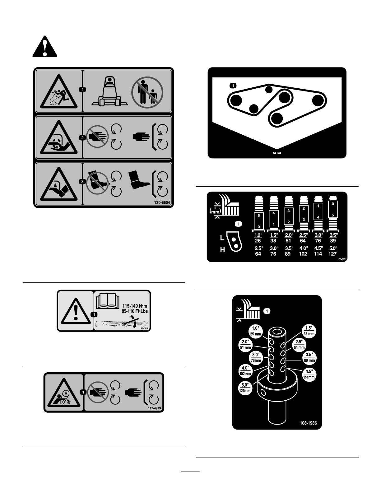
SafetyandInstructionalDecals
Safetydecalsandinstructionsareeasilyvisibletotheoperatorandarelocatednearanyareaof
potentialdanger.Replaceanydecalthatisdamagedorlost.
108-1988
1.Beltrouting
120-6604
1.Thrownobjecthazard—keepbystandersawayfromthe
machine.
2.Cutting/dismembermenthazardofhand,mower
blade—stayawayfrommovingparts,keepallguardsand
shieldsinplace.
3.Cutting/dismembermenthazardoffoot,mowerblade—stay
awayfrommovingparts,keepallguardsandshieldsin
place.
93-7818
1.Warning—readtheOperator'sManualforinstructionson
torquingthebladebolt/nutto115-149N-m(85-1 10ft-lb).
100-5622
1.Heightofcutadjustment
117–4979
1.Entanglementhazard,belt—stayawayfrommovingparts,
keepallguardsandshieldsinplace.
108-1986
1.Heightofcut
6
Page 7
Setup
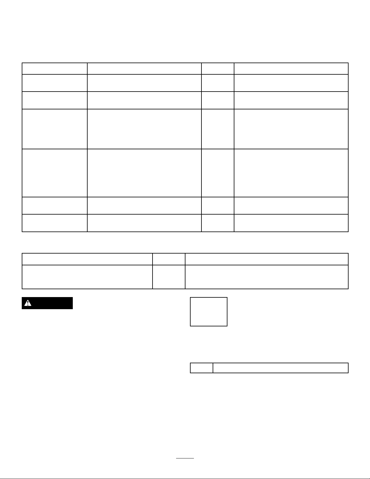
LooseParts
Usethechartbelowtoverifythatallpartshavebeenshipped.
ProcedureDescription
1
2
3
4
5
6
Completionkit(soldseparately)
Castorwheelassembly
Liftarm,right
Liftarm,left
Liftcylinderpin
Cylindercarriagebolt
Cylinderangenut
Thrustwasher4
Clevispin
Hairpincotter2
Height-of-cutcollar
Clevispin
Hairpincotter2
Nopartsrequired
Nopartsrequired
Qty.
1Installacompletionkit.
2Installthecastorwheelassemblies.
1
1
2
2
2
4
2
2
–
–
Installtheliftarms.
Installthecuttingunits
Connectthehydraulicdrive.
Greasethemachine.
Use
MediaandAdditionalParts
Description
PartsCatalog
Operator'sManual
Certicateofcompliance
Qty.
1
1
1
DANGER
Iftheengineisstartedandthehydraulichosesare
notcorrectlyconnectedseriousinjurycouldresult.
Makesurethehydraulichosesarecorrectly
connectedorblankingplugshavebeenttedbefore
startingtheengineandengagingthecuttingunit.
Note:Determinetheleftandrightsidesofthemachine
fromthenormaloperatingposition.
Use
1
InstallingaCompletionKit
Partsneededforthisprocedure:
1
Completionkit(soldseparately)
Procedure
Installoneofthefollowing62inchor72inch
completionkitstothebasedeckusingtheinstruction
providedinthekit:
•Model30648,62inchRearDischarge
•Model30306,62inchGuardian
7
Page 8
•Model30649,72inchRearDischarge
g017949
1
2
3
4
5
6
7
8
1
2
3
6
7
8
•Model30304,72inchGuardian
2
InstallingtheCastorWheel
Assemblies
Partsneededforthisprocedure:
2
Castorwheelassembly
3
InstallingtheLiftArms
Partsneededforthisprocedure:
1
Liftarm,right
1
Liftarm,left
2
Liftcylinderpin
2
Cylindercarriagebolt
2
Cylinderangenut
Procedure
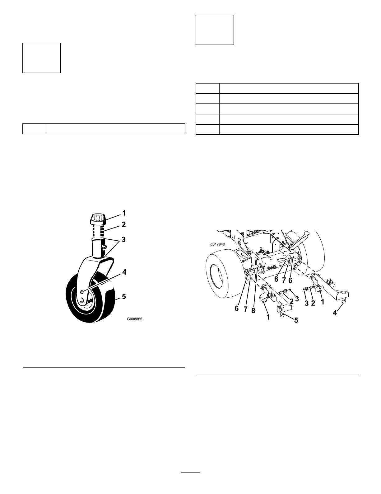
Thethrustwashers,spacers,andtensioningcapshave
beeninstalledonthecastorwheelspindlesforshipping.
1.Removethetensioningcapsfromthespindle
shaftsandslideoffthespacersandthrustwashers
Figure2).
(
Figure2
Procedure
1.Releasethecabletiesthatareholdingupthetraction
unitliftcylindersandlowerittotheoor.
2.Openandraisethetractionunit’soperatorplatform.
3.Fromundertheraisedoperatorplatform,remove
thenutsandcarriageboltsthatsecuretheliftarm
pivotpinstothetractionunitandremovetheLH
andRHliftarmpivotpins(
Figure3
Figure3).
1.Tensioningcap4.Axlemountingholes
2.Spacers5.Castorwheel
3.Thrustwashers
2.Slidethespacersontothecastorspindletogetthe
desiredheight-of-cut;refertoFigure7&Figure8to
determinethecombinationsofspacersforthe
setting.Slideathrustwasherontothespindle,push
thecastorthroughthecastorarm.Installanother
thrustwasherandtheremainingspacersontothe
spindleandinstallthetensioningcaptosecurethe
assembly(Figure2).
1.Cylindercarriagebolt5.RHliftarm
2.Liftcylinderpin6.Liftarmcarriagebolt
3.Cylinderangenut7.Liftarmpivotpin
4.LHliftarm8.Liftarmnut
4.Mounttheliftarmstothetractionunitwiththe
bendspositionedoutwards,andsecureitusingthe
previouslyremovedliftarmpivotpins,carriagebolts,
andnuts(Figure3).
5.Raiseandsecuretheliftarms.
6.Turnonthetractionunit’signitionandmovethe
cuttingunittotheoatposition.
8
Page 9

7.Securetheliftcylinderstotheliftarmsusingthe
g017950
1
2
3
4
5
6
7
8
9
10
suppliedliftcylinderpins,carriagebolts,andnuts
(Figure3).
8.Turnoffthetractionunit,andlowerandsecurethe
operatorplatform.
4
InstallingtheCuttingUniton
theLiftArms
Partsneededforthisprocedure:
4Thrustwasher
4
Clevispin
2Hairpincotter
2
Height-of-cutcollar
2
Clevispin
2Hairpincotter
Procedure
Figure4
1.Liftarm6.Clevispin
2.Castorarmbracket
3.Height-of-cutrod8.Height-of-cutcollar
4.Liftarmpads9.Clevispin
5.Thrustwashers10.Hairpincotter
7.Hairpincotter
1.Movethecuttingunitintopositioninfrontofthe
tractionunit.
2.Turnonthetractionunit’signitionandmovethe
cuttingunittotheoatposition.Pushaliftarm
downuntiltheholesintheliftarmlineupwiththe
holesinthecastorarmbracketandtheheightofcut
rodcanbeinsertedintotheliftarmpads(
3.Securetheliftarmtothecastorarmwith2thrust
washers,aclevispinandahairpincotter.Position
thethrustwashersbetweentheliftarmandthecastor
armbracket(
theslotinthecastorarmtabtoretaincotterpin.
4.Repeattheprocedureontheoppositeliftarm.
5.Startthetractionunitandraisethecuttingunit.
6.Pushdownontherearofthecuttingunitandinsert
7.Installtheheightofcutcollarsontotheheightof
8.Lowerthedeckandswitchthetractionunitignition
theheightofcutrodsthroughtheliftarmpads.
cutrodsandsecurewiththeclevispinsandhairpin
cotters(Figure4).
switchtotheoffposition.
Figure4).Insertendofcotterpininto
Figure4).
5
ConnectingtheHydraulic
Drive
NoPartsRequired
Procedure
Important:Foryoursafetythecuttervalveelectrical
connectorhasbeendisconnectedtodisablethe
operationofthecutterdrive.Reconnectthe
electricalconnectoronceallhoselineconnections
havebeenmadecorrectly.
9
Page 10

WARNING
g017951
1
2
3
4
5
6
g017952
1
Hydraulicuidescapingunderpressurecan
penetrateskinandcauseinjury.
•Makesureallhydraulicuidhosesandlinesare
ingoodconditionandallhydraulicconnections
andttingaretightbeforeapplyingpressureto
thehydraulicsystem.
•Keepyourbodyandhandsawayfrompin
holeleaksornozzlesthatejecthighpressure
hydraulicuid.
•Usecardboardorpapertondhydraulicleaks.
•Safelyrelieveallpressureinthehydraulicsystem
beforeperforminganyworkonthehydraulic
system.
•Seekimmediatemedicalattentionifuidis
injectedintotheskin.
Note:Somehydraulicuidlossmayoccur.
1.Turnoffthecutters,lowerthecuttingunits,stopthe
engine,engagetheparkingbreak,andremovethe
ignitionkey .
A.Removethehoselineendplug.
B.Removetheportcap.
C.Connectthehosetotheport.
D.Tighteneachhoseconnection.
4.Ensurethatallhosesarecorrectlyrouted,
connectionscleaned,andhoselinestightened.
Retainthehoseplugsandportcapsforfutureuse.
5.Usethecabletiesprovidedtosecurethehoselines.
6.Raisethetractionunit’soperatorplatform,and
connectthecuttervalveelectricalconnector
Figure6).
(
2.Cleantheareasaroundthehydraulicportsandthe
hydraulichoselineends(
Figure5).
Figure6
7.Checktheuidlevels,securethetractionunit’s
operatorplatform,andverifythatthecutterdeck
isworkingcorrectly.
6
Figure5
1.Cap5/8,blanking4.Drainport(tocuttervalve
2.Cap3/8,blanking5.Returnport(tocuttervalve
3.Cableties6.Pressureport(fromcutter
3.Identifythe3hydraulichoselinesandports.Referto
Figure5foreachhose’sappropriateport.Perform
thefollowingprocessforeachconnection:
teeonCDport)
M2port)
valveM1port)
GreasingtheMachine
NoPartsRequired
Procedure
Beforeoperatingthemachine,itmustbegreased
toensureproperlubricatingcharacteristics;referto
GreasingtheBearingsandBushings.Failuretoproperly
greasethemachinewillresultinprematurefailureof
criticalparts.
10
Page 11

ProductOverview
Operation
Specications
Note:Specicationsanddesignaresubjecttochange
withoutnotice.
Widthof
Cut
Height
ofCut
Net
Weight
Attachments/Accessories
AselectionofToroapprovedattachmentsand
accessoriesareavailableforusewiththemachineto
enhanceandexpanditscapabilities.Contactyour
AuthorizedServiceDealerorDistributororgoto
www.T oro.comforalistofallapprovedattachments
andaccessories.
62inches(1.575m)or72inches(1.829m)
Adjustablefrom1to5inches(25to127mm)in1/2
inch(13mm)increments
Model30645–463lbs.(210kg)
Model30646–496lbs.(225kg)
Note:Determinetheleftandrightsidesofthe
machinefromthenormaloperatingposition.
CAUTION
Ifyouleavethekeyintheignitionswitch,someone
couldaccidentlystarttheengineandseriously
injureyouorotherbystanders.
Removethekeyfromtheignitionbeforeyoudo
anymaintenance.
AdjustingtheHeight-of-Cut
Theheight-of-cutisadjustablefrom1to5inches(25
to127mm)in1/2inch(13mm)increments.Toadjust
theheight-of-cut,positionthecastorwheelaxlesinthe
upperorlowerholesofthecastorforks,addorremove
anequalnumberofspacersfromthecastorforksand
securetheheightofcutcollartothedesiredholesin
theheightofcutrod.
1.Starttheengineandraisethecuttingunitoffthe
oorsothattheheight-of-cutcanbechanged.Stop
theengineandremovethekeyafterthecuttingunit
israised.
2.Positionthecastorwheelaxlesinthesameholesin
bothcastorforks.Referto
determinethecorrectholesforthesetting.
Note:Whenoperatingin2–1/2inch(64mm)
heightofcutorhigher,theaxleboltmustbe
installedinthelowercastorforkholetoprevent
grassbuildupbetweenthewheelandthefork.
Whenoperatinginheightofcutslowerthan2–1/2
inches(64mm)andgrassbuildupisdetected,
reversethemachinesdirectiontopullanyclippings
awayfromthewheel/forkarea.
3.Removethetensioningcapfromthespindleshaft
Figure7)andslidethespindleoutofthecastor
(
arm.Putthe2shims(1/8inch)ontothespindle
shaftastheywereoriginallyinstalled.Theseshims
arerequiredtoachievealevelacrosstheentirewidth
ofthecuttingunits.Slidetheappropriatenumber
of1/2inchspacersontothespindleshafttogetthe
desiredheight-of-cut;thenslidethewasheronto
theshaft.
Referto
combinationsofspacersforthesetting.
Figure7&Figure8todeterminethe
Figure7&Figure8to
11
Page 12

Figure9
Figure7
1.Tensioningcap4.Axlemountingholes
2.Spacers5.CastorWheel
3.Shims
Figure8
4.Pushthecastorspindlethroughthecastorarm.
Installtheshims(astheywereoriginallyinstalled)
andtheremainingspacersontothespindleshaft.
Installthetensioningcaptosecuretheassembly.
1.Height-of-cutrod3.Clevispinandhairpin
cotter
2.Height-of-cutcollar
6.Aligntheheight-of-cutcollartothedesired
height-of-cutholesontheheightofcutrod
(Figure10).
5.Removethehairpinandclevispinsecuringthe
heightofcutcollartotheheightofcutrodonthe
rearofthecuttingunit(
Figure9).
Figure10
7.Securetheadjustmentwiththeclevispinandhair
pin.
Note:Positiontheheadoftheclevispintoward
thefrontofthedeck,ifpossible.
Note:Whenusing1inch(25mm),1-1/2inch(38
mm),oroccasionally2inch(51mm)height–of–cut,
movetheskidsandrollertothehighestholes.
AdjustingtheCuttingUnit
Pitch
Cuttingunitpitchisthedifferenceinheight-of-cut
fromthefrontofthebladeplanetothebackofthe
bladeplane.Tororecommendsabladepitchof1/2
12
Page 13

inch(13mm).Thatisthebackofthebladeplaneis1/2
inch(13mm)higherthanthefront.
1.Positionthemachineonalevelsurfaceontheshop
oor.
2.Setthecuttingunittothedesiredheight-of-cut.
3.Rotate1bladesothatitpointsstraightforward.
4.Usingashortruler,measurefromtheoortothe
fronttipoftheblade.Rotatethebladetiptotherear
andmeasurefromtheoortothetipoftheblade.
Figure12
5.Subtractthefrontdimensionfromtherear
dimensiontocalculatethebladepitch.
6.Loosenthejamnutsonthebottomofthe
height-of-cutrods(
1.Height-of-cut
7.Rotatetheheight-of-cutrodstoraiseorlowerthe
rearofthecuttingunitandattainthecorrectcutting
unitpitch.
Figure11).
Figure11
2.Jamnut
1.Skid
AdjustingtheRollers
Note:Ifthecuttingunitistobeusedinthe1or1-1/2
inch(25or38mm)height-of-cutsetting,thecutting
unitrollersmustberepositionedinthetopbracket
holes.
1.Removethescrewandnutsecuringtherollershaft
tothedeckbracket(
Figure13).
8.Tightenthejamnuts.
AdjustingtheSkids
Theskidsshouldbemountedinthelowerposition
whenoperatinginheightofcutsgreaterthan2-1/2
inches(64mm)andinthehigherpositionwhen
operatinginheightofcutslowerthan2-1/2inches(64
mm).
Adjusttheskidsbyremovingtheangeboltandnuts,
positioningthemasdesired,andinstallingthefasteners
(Figure12).
Figure13
1.Roller
2.Slidetheshaftoutofthelowerbracketholes,align
therollerwiththetopholes,andinstalltheshaft.
3.Installthescrewandnuttosecuretheassemblies.
2.Rollershaft
CorrectingCuttingUnit
Mismatch
Duetodifferencesingrassconditionsandthe
counterbalancesettingofthetractionunit,itisadvised
thatgrassbecutandappearancecheckedbeforeformal
cuttingisstarted.
1.Setthecuttingunittothedesiredheightofcut;
refertoAdjustingtheHeightofCut.
13
Page 14

2.Checkandadjustfrontandreartractortirepressure
to10psi(0.7BAR).
3.Checkandadjustallcastortirepressuresto50psi
(3.4BAR).
4.Checkforbentblades;refertoCheckingforaBent
Blade.
5.Cutgrassinatestareatodetermineifallcutting
unitsarecuttingatthesameheight.
6.Ifcuttingunitadjustmentsarestillneeded,ndaat
surfaceusinga6foot(2m)orlongerstraightedge.
7.Toeasemeasuringbladeplane,raisetheheightof
cuttothehighestposition;refertoAdjustingthe
HeightofCut.
8.Lowercuttingunitontotheatsurface.Remove
thecoversfromthetopofthecuttingunits.
9.Rotatethebladeoneachspindleuntiltheendsface
forwardandbackward.
10.Measurefromtheoortothefronttipofthe
cuttingedge.
11.Adjust1/8inch(3mm)shimsoncastorfork(s)to
matchheightofcuttodecal(
AdjustingtheCuttingUnitPitch.
Figure14);referto
damagethatcanbecausedbydirectsunlightonthe
sensitive,freshlymowedgrass.
SelecttheProperHeight-of-CutSetting
toSuitConditions
Removeapproximately1inch(25mm)ornomorethan
1/3ofthegrassbladewhencutting.Inexceptionally
lushanddensegrass,youmayhavetoraisethe
height-of-cuttothenextsetting.
MowatProperIntervals
Undermostnormalconditionsyouwillneedtomow
approximatelyevery4–5days.Butremember,grass
growsatdifferentratesatdifferenttimes.Thismeans
thatinordertomaintainthesameheight-of-cut,which
isagoodpractice,youwillneedtocutmorefrequently
inearlyspring;asthegrassgrowthrateslowsinmid
summer,cutonlyevery8–10days.Ifyouareunableto
mowforanextendedperiodduetoweatherconditions
orotherreasons,mowrstwiththeheight-of-cutata
highlevel;thenmowagain2–3dayslaterwithalower
heightsetting.
AlwaysMowwithSharpBlades
Figure14
1.Tensioningcap4.Axlemountingholes
2.Spacers5.Castorwheel
3.Shims
OperatingTips
Asharpbladecutscleanlyandwithouttearingor
shreddingthegrassbladeslikeadullblade.Tearingand
shreddingcausesthegrasstoturnbrownattheedges
whichimpairsgrowthandincreasessusceptibilityto
diseases.
AfterOperating
Toensureoptimumperformance,cleantheunderside
ofthemowerhousingaftereachuse.Ifresidueis
allowedtobuildupinthemowerhousing,cutting
performancewilldecrease.
CuttingUnitPitch
Werecommendabladepitchof1/2inch(13mm).A
pitchlargerthan1/2inch(13mm)willresultinless
powerrequired,largerclippings,andapoorerquality
ofcut.Apitchlessthan1/2inch(13mm)willresult
inmorepowerrequired,smallerclippingsandabetter
qualityofcut.
MowWhenGrassisDry
Moweitherinthelatemorningtoavoidthedew,which
causesgrassclumping,orinlateafternoontoavoidthe
14
Page 15

Maintenance
RecommendedMaintenanceSchedule(s)
MaintenanceService
Interval
Aftertherst2hours
Aftertherst10hours
Beforeeachuseordaily
Every50hours
Every400hours
1
Immediatelyaftereverywashing,regardlessoftheintervallisted
MaintenanceProcedure
•Tightenthecastorwheelnuts
•Tightenthecastorwheelnuts
•T orquethebladebolts
•Checktheblades
•Lubricatethegreasettings1
•Checkthegearboxoillevel
•Tightenthecastorwheelnuts
•T orquethebladebolts
•Checkthebladedrivebeltadjustment
•Cleanunderthecuttingunitbeltcovers
•Changethegearboxoil
CAUTION
Ifyouleavethekeyintheignitionswitch,someonecouldaccidentallystarttheengineandseriously
injureyouorotherbystanders.
Removethekeyfromtheignitionswitchbeforeyoudoanymaintenance.
Important:Thefastenersonthecoversofthismachinearedesignedtoremainonthecoverafterremoval.
Lubrication
Themachinehasgreasettingsthatmustbelubricated
regularlywithNo.2GeneralPurposeLithiumBase
Grease.Ifthemachineisoperatedundernormal
conditions,lubricateallbearingsandbushingsafter
every50hoursofoperationorimmediatelyafterevery
washing.
Lubricatethefollowingareas:
•Castorforkshaftbushings(2)(
Figure15)
Figure15
•Spindleshaftbearings(3)(locatedunderthepulley)
(Figure16).
15
Page 16

g017953
Figure16
g017954
g017955
g017956
1
2
3
4
5
6
8
7
9
10
•Idlerarmshaftbearings(Figure16).
•Liftarmpivots,front(2)(
Figure17).
TiltingtheCuttingUnitfor
Maintenance
Topreparetheunitformaintenance:
1.Positionthemachineonalevelsurface,raisethe
cuttingunit,turnofftheengine,engagetheparking
break,andapplytheliftarmlatches.
Note:Ifthecuttingunitisa72inch(183cm)
modelwithareardischargekittted,therearLH
footguardshouldberemovedpriortocarryingout
thisoperation.
2.Removethehairpinandclevispinsecuringthe
height-of-cutcollartotheheight-of-cutrodonthe
rearofthecuttingunit(
height-of-cutcollars.
Figure19).Removethe
Figure17
•Liftarmpivots,rear(2)(Figure18).
Figure18
Figure19
1.Liftarmlatches6.Liftarmpads
2.Hairpincotter
3.Clevispin
4.Height-of-cutcollar9.RHliftarm
5.Height-of-cutrod
7.Clevispin
8.Hairpincotter
10.RHcasterarm
3.Pivotthedeckuntiltheclevispincanbeinserted
throughtheholeintheRHcastorarmandsecure
ittotheRHliftarm.Securetheclevispinwitha
haripincotter(Figure19).
Tolowerthedeckfromthetiltedposition:
1.Removethehairpincotter.Liftthedeckuntilthe
clevispincanbeeasilyremovedfromtheholeinthe
RHcastorarm(
Figure19).
2.Lowerandtiltthedeckbackensuringthe
height-of-cutrodsdonotgetcaughtonanypartof
thetractionunit.
3.Pushdownontherear,right-handsideofthecutting
unitandinserttheheight-of-cutrodsthroughthe
16
Page 17

liftarmpads.RepeatfortheLHside,makingsure
g017957
1
2
3
g017958
1
2
3
4
g017959
1
2
3
theRHsideheight-of-cutroddoesnotfallout
(Figure19).
4.Installtheheight-of-cutcollarsontotheheight-of-cut
rodsandsecurethemwiththeclevispinsandhair
pincotters(
Figure19).Makesuretheheadofthe
clevispinistowardthefrontofthedeck.
SeparatingtheCuttingUnit
fromtheTractionUnit
1.Positionthemachineonlevelsurface,raisethe
cuttingunit,movetheliftlevertotheFloatposition,
shuttheengineoff,andengagetheparkingbrake.
2.Removethehairpinandclevispinsecuringthe
height-of-cutrodtotherearofthecuttingunit
Figure20).Removetheheight-of-cutcollars.
(
Figure20
Figure21
1.Liftarm
2.Clevispin4.Castorarmbracket
3.Hairpincotter
5.Removethehydraulicmotorcovers,removethe
bolts,thenremovethehydraulicmotorfromthe
cuttingunit.(Figure22).
1.Height-of-cutrod
2.Height-of-cutcollar
3.Turnontheignitionswitchandlowerthecutting
unittotheoor.Leavetheliftswitchintheoat
position.
Note:Makesuretheengineisnotrunning.
4.Removethehairpincottersandclevispinssecuring
theliftarmstothecastorarmbrackets(Figure21).
3.Hairpincotterandclevis
pin
Figure22
6.Raisetheliftarms,latchthemintheraisedposition,
androllthecuttingunitawayfromthetractionunit.
Turnofftheignitionswitch.
DANGER
Donotengagethecuttingunitdrivewhilethe
hydraulicmotorisnotconnectedtothecutting
unit.
MountingtheCuttingUnitto
theTractionUnit
1.Positionthemachineonalevelsurfaceandshutthe
17
engineoff.Leavetheignitionswitchon.
Page 18

2.Movethecuttingunitintopositioninfrontofthe
g017960
1
2
3
4
5
6
7
8
9
10
tractionunit.
3.Installthehydraulicmotorontothecuttingunit,
secureitusingthetwobolts,theninstallthetwo
hydraulicmotorcovers(
Figure22).
4.MovetheliftswitchtotheFloatposition.Pusha
liftarmdownuntiltheholesintheliftarmlineup
withtheholesinthecastorarmbracketandthe
heightofcutrodcanbeinsertedintotheliftarm
pads(Figure23).
pincotters(
Figure23).Headofclevispintobe
positionedtowardthefrontofthedeck.
ServicingtheBushingsinthe
CastorArms
Thecastorarmshavebushingspressedintothetopand
bottomofthetubeandaftermanyhoursofoperation,
thebushingswillwear.Tocheckthebushings,movethe
castorforkbackandforthandfromsidetoside.Ifthe
castorspindleislooseinsidethebushings,thebushings
arewornandmustbereplaced.
1.Raisethecuttingunitsothatthewheelsareoffof
theoor.Latchthecuttingunitsothatitcannot
accidentallyfall.
2.Removethetensioningcap,spacer(s),andthrust
washerfromthetopofthecastorspindle.
3.Pullthecastorspindleoutofthemountingtube.
Allowthethrustwasherandspacer(s)toremainon
thebottomofthespindle.
4.Insertapinpunchintothetoporbottomofthe
mountingtubeanddrivethebushingoutofthetube
Figure24).Alsodrivetheotherbushingoutofthe
(
tube.Cleantheinsideofthetubestoremovedirt.
Figure23
1.Liftarm6.Clevispin
2.Castorarmbracket
3.Height-of-cutrod8.Height-of-cutcollar
4.Liftarmpads9.Clevispin
5.Thrustwashers10.Hairpincotter
5.Securetheliftarmtothecastorarmwith(2)thrust
washers,aclevispinandahairpincotter.Position
thethrustwashersbetweentheliftarmandthecastor
armbracket(Figure23).Insertendofcotterpininto
theslotinthecastorarmtabtoretaincotterpin.
7.Hairpincotter
6.Repeattheprocedureontheoppositeliftarm.
7.Startthetractionunitandraisethecuttingunit.
8.WorkingontheRHside,pushdownontherear
ofthecuttingunitandinserttheheightofcutrods
throughtheliftarmpads.RepeatontheLHside
takingcarenottoallowtheRHsideheight-of-cut
rodtofallout.
9.Installtheheightofcutcollarsontotheheightof
cutrodsandsecurewiththeclevispinsandhair
Figure24
1.Castorarmtube
2.Bushings
5.Applygreasetotheinsideandoutsideofthenew
bushings.Usingahammerandatplate,drivethe
bushingsintothemountingtube.
6.Inspectthecastorspindleforwearandreplaceitif
damaged.
7.Pushthecastorspindlethroughthebushingsand
mountingtube.Slidethethrustwasherandspacer(s)
ontothespindle.Installthetensioningcaponthe
castorspindletoretainallpartsinplace.
ServicingtheCastorWheels
andBearings
1.Removethelocknutfromtheboltholdingthecastor
wheelassemblybetweenthecastorfork(Figure25).
18
Page 19

Graspthecastorwheelandslidetheboltoutofthe
G010549
G010555
1
2
forkorpivotarm.
Figure25
1.Castorwheel3.Bearing(2)
2.Castorfork
4.Bearingspacer
2.Removethebearingfromthewheelhubandallow
thebearingspacertofallout(Figure25).Remove
thebearingfromtheoppositesideofthewheelhub.
3.Checkthebearings,spacer,andinsideofthewheel
hubforwear.Replaceanydamagedparts.
4.Toassemblethecastorwheel,pushthebearinginto
thewheelhub.Wheninstallingthebearings,press
ontheouterraceofthebearing.
5.Slidethebearingspacerintothewheelhub.Pushthe
otherbearingintotheopenendofthewheelhubto
captivatethebearingspacerinsidethewheelhub.
Figure26
3.Rotatetheoppositeendofthebladeforward.
Measurebetweenthecuttingunitandcuttingedge
ofthebladeatthesamepositionasinstep2The
differencebetweenthedimensionsobtainedin
steps2and3mustnotexceed1/8inch(3mm).If
thedimensionexceeds1/8inch(3mm),replace
thebladebecauseitisbent;refertoRemovingthe
CuttingBlade.
RemovingandInstallingthe
Blade(s)
Theblademustbereplacedifasolidobjectishit,the
bladeisout-of-balance,worn,orbent.Alwaysuse
genuineTororeplacementbladestoensuresafetyand
optimumperformance.Neverusebladesmadebyother
manufacturersbecausetheycouldbedangerous.
1.Raisethecuttingunittothehighestposition,engage
theparkingbrake,stoptheengine,andremovethe
ignitionkey.Latchthecuttingunittopreventitfrom
accidentallyfalling.
2.Grasptheendofthebladeusingaragorthickly
paddedglove.Removethebladebolt,anti-scalpcup,
andbladefromthespindleshaft(
Figure27).
6.Installthecastorwheelassemblybetweenthecastor
forkandsecureitinplacewiththeboltandlocknut.
CheckingforaBentBlade
1.Positionthemachineonalevelsurface.Raisethe
cuttingunit,engagetheparkingbrake,putthe
tractionpedalinneutral,putthecuttingunitdrive
switchintheOffposition,stoptheengine,and
removetheignitionkey.Latchthecuttingunitto
preventitfromaccidentallyfalling.
2.Rotatethebladeuntiltheendsfaceforwardand
backward.Measurefromtheinsideofthecutting
unittothecuttingedgeatthefrontoftheblade
(Figure26),andrememberthisdimension.
Figure27
1.Bladebolt2.Anti-scalpcup
3.Installtheblade-sailfacingtowardthecutting
unit-withtheanti-scalpcupandbladebolt.Tighten
thebladeboltto85-110ft-lb(115-149N-m).
Important:Thecurvedpartoftheblademust
bepointingtowardtheinsideofthecuttingunit
toensurepropercutting .
19
Page 20

InspectingandSharpeningthe
Blade(s)
DANGER
Awornordamagedbladecanbreak,andapiece
ofthebladecouldbethrownintotheoperator's
orbystander'sarea,resultinginseriouspersonal
injuryordeath.
•Inspectthebladeperiodicallyforwearor
damage.
•Donottrytostraightenabladethatisbent.
Figure28
1.Cuttingedge3.Wear/slotforming
2.Curvedarea/sail4.Crack
•Neverweldabrokenorcrackedblade.
•Replaceawornordamagedbladewitha
newT orobladetoensurecontinuedsafety
certicationoftheproduct.
Twoareasmustbeconsideredwhencheckingand
servicingthecuttingblade:thesailandthecuttingedge.
Bothcuttingedgesandthesail,whichistheturnedup
portionoppositethecuttingedge,contributetoagood
quality-of-cut.Thesailisimportantbecauseitpullsgrass
upstraight,therebyproducinganevencut.However,
thesailwillgraduallyweardownduringoperation,and
thisconditionisnormal.Asthesailwearsdown,the
quality-of-cutwilldegradesomewhat,althoughthe
cuttingedgesaresharp.Thecuttingedgeoftheblade
mustbesharpsothatthegrassiscutratherthantorn.
Adullcuttingedgeisevidentwhenthetipsofthegrass
appearbrownandshredded.Sharpenthecuttingedges
tocorrectthiscondition.
1.Positionthemachineonalevelsurface.Raisethe
cuttingunit,engagetheparkingbrake,putthe
tractionpedalinneutral,putthecuttingunitdrive
switchintheOffposition,stoptheengine,remove
theignitionkey,andapplytheliftarmlatches.
WARNING
Ifthebladeisallowedtowear,aslotwillform
betweenthesailandatpartoftheblade
Figure28).Eventually,apieceoftheblademay
(
breakoffandbethrownfromunderthehousing,
possiblyresultinginseriousinjurytoyourself
orbystanders.
•Inspectthebladeperiodicallyforwearor
damage.
•Replaceawornordamagedbladewitha
newTorobladetoensurecontinuedsafety
certicationoftheproduct.
3.Examinethecuttingedgesofallblades.Sharpenthe
cuttingedgesiftheyaredullornicked.Sharpenonly
thetopsideofthecuttingedgeandmaintainthe
originalcuttingangletoensuresharpness(Figure29).
Thebladewillremainbalancedifthesameamount
ofmetalisremovedfrombothcuttingedges.
2.Examinethecuttingendsofthebladecarefully,
especiallywheretheatandcurvedpartsofthe
blademeet(
materialcanwearawaythemetalthatconnects
theatandcurvedpartsoftheblade,checkthe
bladebeforeusingthemachine.Ifwearisnoticed
(Figure28),replacetheblade;refertoRemovingthe
CuttingBlade.
Figure28).Sincesandandabrasive
Figure29
1.Sharpenatoriginalangle
Note:Removethebladesandsharpenthemona
grinder;refertoRemovingtheCuttingBlades.After
sharpeningthecuttingedges,installthebladewith
theanti-scalpcupandbladebolt.Thebladesails
mustbeontopoftheblade.Tightenthebladebolt
to85-110ft-lb(115-149N-m).
20
Page 21

CheckingandCorrecting
g017961
1
2
g017962
1
2
MismatchofBlades
Ifthereismismatchbetweentheblades,thegrasswill
appearstreakedwhenitiscut.Thisproblemcanbe
correctedbymakingsurethatthebladesarestraightand
allofthebladesarecuttingonthesameplane.
1.Usinga3foot(1meter)longcarpenterslevel,nd
alevelsurfaceontheshopoor.
2.Raisetheheight-of-cuttothehighestposition;refer
toAdjustingtheHeight-of-Cut.
3.Lowerthecuttingunitontotheatsurface.Remove
thecoversfromthetopofthecuttingunit.
4.Rotatethebladesuntiltheendsfaceforwardand
backward.Measurefromtheoortothefronttipof
thecuttingedge.Rememberthisdimension.Then
rotatethesamebladesothattheoppositeendis
forward,andmeasureagain.Thedifferencebetween
thedimensionsmustnotexceed1/8inch(3mm).
Ifthedimensionexceeds1/8inch(3mm),replace
thebladebecauseitisbent.Makesuretomeasure
alloftheblades.
5.Comparethemeasurementsoftheouterblades
withthecenterblade.Thecenterblademustnotbe
morethan3/8inch(10mm)lowerthantheouter
blades.Ifthecenterbladeismorethan3/8inch(10
mm)lowerthantheouterblades,proceedtostep
andaddshimsbetweenthespindlehousingandthe
bottomofthecuttingunit.
1.Lowerthecuttingunittotheshopoor.Remove
thebeltcoversfromthetopofthecuttingunitand
setthecoversaside.
2.Usingatorquewrenchorsimilartool,movetheidler
pulley(Figure30)awayfromthedrivebelttorelease
thebelttensionandallowthebelttobeslippedoff
thexedidlerpulley(Figure30).
Figure30
1.Idlerpulley2.Fixedidlerpulley
6
6.Removethebolts,atwashers,lockwashers,and
nutsfromtheouterspindleintheareawherethe
shimsmustbeadded.Toraiseorlowertheblade,
addashim,PartNo.3256-24,betweenthespindle
housingandthebottomofthecuttingunit.Continue
tocheckthealignmentofthebladesandaddshims
untilthetipsofthebladesarewithintherequired
dimension.
Important:Donotusemorethanthreeshimsat
anyoneholelocation.Usedecreasingnumbers
ofshimsinadjacentholesifmorethanoneshim
isaddedtoanyoneholelocation.
7.Installthebeltcovers.
ReplacingtheDriveBelt
Thebladedrivebelt,tensionedbythespringloaded
idlerpulley,isverydurable.However,aftermanyhours
ofuse,thebeltwillshowsignsofwear.Signsofaworn
beltare:squealingwhenbeltisrotating,bladesslipping
whencuttinggrass,frayededges,burnmarksandcracks.
Replacethebeltifanyoftheseconditionsareevident.
Figure31
1.Bolts2.Hydraulicmotor
3.Removetheboltsandhydraulicmotorasshownin
Figure31.
4.Removetheoldbeltfromaroundtheremaining
pulleys.
5.Routethenewbeltaroundthespindlepulleysand
idlerpulleyassemblyasshowninFigure32.
21
Page 22

Figure32
1.Beltrouting
6.Installthehydraulicmotorandsecureitwiththe
boltsremovedearlier(Figure31).
7.Installthebeltcovers.
22
Page 23

Notes:
23
Page 24

TheT oroT otalCoverageGuarantee
ALimitedWarranty
ConditionsandProductsCovered
TheT oroCompanyanditsafliate,T oroWarrantyCompany ,pursuant
toanagreementbetweenthem,jointlywarrantyourT oroCommercial
product(“Product”)tobefreefromdefectsinmaterialsorworkmanship
fortwoyearsor1500operationalhours*,whicheveroccursrst.This
warrantyisapplicabletoallproductswiththeexceptionofAerators
(refertoseparatewarrantystatementsfortheseproducts).Wherea
warrantableconditionexists,wewillrepairtheProductatnocosttoyou
includingdiagnostics,labor,parts,andtransportation.Thiswarranty
beginsonthedatetheProductisdeliveredtotheoriginalretailpurchaser.
*Productequippedwithanhourmeter.
InstructionsforObtainingWarrantyService
YouareresponsiblefornotifyingtheCommercialProductsDistributoror
AuthorizedCommercialProductsDealerfromwhomyoupurchasedthe
Productassoonasyoubelieveawarrantableconditionexists.Ifyouneed
helplocatingaCommercialProductsDistributororAuthorizedDealer,or
ifyouhavequestionsregardingyourwarrantyrightsorresponsibilities,
youmaycontactusat:
ToroCommercialProductsServiceDepartment
ToroWarrantyCompany
811 1LyndaleAvenueSouth
Bloomington,MN55420-1196
952–888–8801or800–952–2740
E-mail:[email protected]
OwnerResponsibilities
AstheProductowner,youareresponsibleforrequiredmaintenance
andadjustmentsstatedinyourOperator'sManual.Failuretoperform
requiredmaintenanceandadjustmentscanbegroundsfordisallowinga
warrantyclaim.
ItemsandConditionsNotCovered
Notallproductfailuresormalfunctionsthatoccurduringthewarranty
periodaredefectsinmaterialsorworkmanship.Thiswarrantydoesnot
coverthefollowing:
•Productfailureswhichresultfromtheuseofnon-Tororeplacement
parts,orfrominstallationanduseofadd-on,ormodiednon-T oro
brandedaccessoriesandproducts.Aseparatewarrantymaybe
providedbythemanufactureroftheseitems.
•Productfailureswhichresultfromfailuretoperformrecommended
maintenanceand/oradjustments.Failuretoproperlymaintainyour
ToroproductpertheRecommendedMaintenancelistedinthe
Operator’sManualcanresultinclaimsforwarrantybeingdenied.
•ProductfailureswhichresultfromoperatingtheProductinan
abusive,negligent,orrecklessmanner.
•Partssubjecttoconsumptionthroughuseunlessfoundtobe
defective.Examplesofpartswhichareconsumed,orusedup,
duringnormalProductoperationinclude,butarenotlimitedto,brake
padsandlinings,clutchlinings,blades,reels,rollersandbearings
(sealedorgreasable),bedknives,sparkplugs,castorwheelsand
bearings,tires,lters,belts,andcertainsprayercomponentssuchas
diaphragms,nozzles,andcheckvalves,etc.
•Failurescausedbyoutsideinuence.Conditionsconsideredtobe
outsideinuenceinclude,butarenotlimitedto,weather,storage
practices,contamination,useofunapprovedfuels,coolants,
lubricants,additives,fertilizers,water,orchemicals,etc.
•Failureorperformanceissuesduetotheuseoffuels(e.g.gasoline,
diesel,orbiodiesel)thatdonotconformtotheirrespectiveindustry
standards.
•Normalnoise,vibration,wearandtear,anddeterioration.
•Normal“wearandtear”includes,butisnotlimitedto,damageto
seatsduetowearorabrasion,wornpaintedsurfaces,scratched
decalsorwindows,etc.
Parts
Partsscheduledforreplacementasrequiredmaintenancearewarranted
fortheperiodoftimeuptothescheduledreplacementtimeforthatpart.
Partsreplacedunderthiswarrantyarecoveredforthedurationofthe
originalproductwarrantyandbecomethepropertyofToro.Torowill
makethenaldecisionwhethertorepairanyexistingpartorassemblyor
replaceit.T oromayuseremanufacturedpartsforwarrantyrepairs.
DeepCycleandLithium-IonBatteryWarranty:
DeepcycleandLithium-Ionbatterieshaveaspeciedtotalnumberof
kilowatt-hourstheycandeliverduringtheirlifetime.Operating,recharging,
andmaintenancetechniquescanextendorreducetotalbatterylife.Asthe
batteriesinthisproductareconsumed,theamountofusefulworkbetween
chargingintervalswillslowlydecreaseuntilthebatteryiscompletelyworn
out.Replacementofwornoutbatteries,duetonormalconsumption,
istheresponsibilityoftheproductowner.Batteryreplacementmaybe
requiredduringthenormalproductwarrantyperiodatowner’sexpense.
Note:(Lithium-Ionbatteryonly):ALithium-Ionbatteryhasapartonly
proratedwarrantybeginningyear3throughyear5basedonthetime
inserviceandkilowatthoursused.RefertotheOperator'sManualfor
additionalinformation.
MaintenanceisatOwner’sExpense
Enginetune-up,lubrication,cleaningandpolishing,replacementoflters,
coolant,andcompletingrecommendedmaintenancearesomeofthe
normalservicesToroproductsrequirethatareattheowner’sexpense.
GeneralConditions
RepairbyanAuthorizedT oroDistributororDealerisyoursoleremedy
underthiswarranty .
NeitherTheToroCompanynorToroWarrantyCompanyisliablefor
indirect,incidentalorconsequentialdamagesinconnectionwiththe
useoftheToroProductscoveredbythiswarranty,includingany
costorexpenseofprovidingsubstituteequipmentorserviceduring
reasonableperiodsofmalfunctionornon-usependingcompletion
ofrepairsunderthiswarranty .ExceptfortheEmissionswarranty
referencedbelow,ifapplicable,thereisnootherexpresswarranty.
Allimpliedwarrantiesofmerchantabilityandtnessforuseare
limitedtothedurationofthisexpresswarranty.
Somestatesdonotallowexclusionsofincidentalorconsequential
damages,orlimitationsonhowlonganimpliedwarrantylasts,sothe
aboveexclusionsandlimitationsmaynotapplytoyou.Thiswarranty
givesyouspeciclegalrights,andyoumayalsohaveotherrightswhich
varyfromstatetostate.
Noteregardingenginewarranty:
TheEmissionsControlSystemonyourProductmaybecoveredby
aseparatewarrantymeetingrequirementsestablishedbytheU.S.
EnvironmentalProtectionAgency(EPA)and/ortheCaliforniaAir
ResourcesBoard(CARB).Thehourlimitationssetforthabovedonot
applytotheEmissionsControlSystemWarranty.RefertotheEngine
EmissionControlWarrantyStatementsuppliedwithyourproductor
containedintheenginemanufacturer’sdocumentationfordetails
CountriesOtherthantheUnitedStatesorCanada
CustomerswhohavepurchasedT oroproductsexportedfromtheUnitedStatesorCanadashouldcontacttheirT oroDistributor(Dealer)toobtain
guaranteepoliciesforyourcountry ,province,orstate.IfforanyreasonyouaredissatisedwithyourDistributor'sserviceorhavedifcultyobtaining
guaranteeinformation,contacttheToroimporter.
374-0253RevB
 Loading...