

Toro Groundsmaster 4000, 30609, Groundsmaster 4010, 30636 Operator's Manual

FormNo.3411-340RevC
Groundsmaster
®
4000or4010
RotaryMower
ModelNo.30609—SerialNo.400000000andUp
ModelNo.30636—SerialNo.400000000andUp
Registeratwww.T oro.com.
OriginalInstructions(EN)
*3411-340*C

ThisproductcomplieswithallrelevantEuropean
directives;fordetailspleaseseetheseparateproduct
specicDeclarationofConformity(DOC)sheet.
WARNING
CALIFORNIA
Proposition65Warning
Thisproductcontainsachemical
orchemicalsknowntotheStateof
Californiatocausecancer,birthdefects,
orreproductiveharm.
Dieselengineexhaustandsomeofits
constituentsareknowntotheStateof
Californiatocausecancer,birthdefects,
andotherreproductiveharm.
ItisaviolationofCaliforniaPublicResourceCode
Section4442or4443touseoroperatetheengineon
anyforest-covered,brush-covered,orgrass-covered
landunlesstheengineisequippedwithaspark
arrester,asdenedinSection4442,maintainedin
effectiveworkingorderortheengineisconstructed,
equipped,andmaintainedforthepreventionofre.
g197124
Figure1
1.Modelandserialnumberlocation
ModelNo.
SerialNo.
Thismanualidentiespotentialhazardsandhas
safetymessagesidentiedbythesafety-alertsymbol
(Figure2),whichsignalsahazardthatmaycause
seriousinjuryordeathifyoudonotfollowthe
recommendedprecautions.
Introduction
Thismachineisaride-on,rotary-bladelawnmower
intendedtobeusedbyprofessional,hiredoperators
incommercialapplications.Itisprimarilydesigned
forcuttinggrassonwell-maintainedlawnsinparks,
sportselds,andoncommercialgrounds.Itisnot
designedforcuttingbrush,mowinggrassandother
growthalongsidehighways,orforagriculturaluses.
Readthisinformationcarefullytolearnhowtooperate
andmaintainyourproductproperlyandtoavoid
injuryandproductdamage.Youareresponsiblefor
operatingtheproductproperlyandsafely .
YoumaycontactT orodirectlyatwww.T oro.comfor
productandaccessoryinformation,helpndinga
dealer,ortoregisteryourproduct.
Wheneveryouneedservice,genuineToroparts,or
additionalinformation,contactanAuthorizedService
DealerorToroCustomerServiceandhavethemodel
andserialnumbersofyourproductready.Figure1
identiesthelocationofthemodelandserialnumbers
ontheproduct.Writethenumbersinthespace
provided.
g000502
Figure2
1.Safety-alertsymbol
Thismanualuses2wordstohighlightinformation.
Importantcallsattentiontospecialmechanical
informationandNoteemphasizesgeneralinformation
worthyofspecialattention.
©2017—TheToro®Company
8111LyndaleAvenueSouth
Bloomington,MN55420
Contactusatwww.Toro.com.
2
PrintedintheUSA
AllRightsReserved

Contents
Safety.......................................................................4
GeneralSafety...................................................4
Engine-EmissionCertication.............................4
SafetyandInstructionalDecals..........................5
Setup......................................................................15
1GreasingtheMachine....................................15
2ReplacingtheWarningDecal.........................15
ProductOverview...................................................16
Controls...........................................................16
CabControls.................................................18
Specications..................................................23
Attachments/Accessories.................................24
BeforeOperation.................................................24
BeforeOperationSafety...................................24
CheckingtheEngine-OilLevel..........................25
CheckingtheCoolingSystem...........................25
CheckingtheHydraulicSystem........................25
FillingtheFuelTank..........................................25
CheckingtheTirePressure...............................27
CheckingtheT orqueoftheWheel-Lug
Nuts..............................................................27
CheckingthePlanetary-Gear-Drive
Oil.................................................................27
CheckingtheRear-AxleLubricant....................28
CheckingtheRear-Axle-Gearbox
Lubricant.......................................................28
AdjustingtheRolloverProtectionSystem
(ROPS).........................................................29
AdjustingtheHeightofCut...............................29
AdjustingtheSkids...........................................32
AdjustingtheMower-DeckRollers....................33
CorrectingaMismatchBetweentheMower
Decks............................................................33
CheckingtheSafety-InterlockSwitches............35
AdjustingtheMirrors.........................................35
AimingtheHeadlights.......................................35
DuringOperation.................................................35
DuringOperationSafety...................................35
StartingandShuttingOfftheEngine.................37
UnderstandingSmartPower.............................37
ReversingFanOperation..................................37
UnderstandingAutoIdle...................................37
UsingCruiseControl.........................................38
CuttingGrasswiththeMachine........................38
DieselParticulateFilterRegeneration...............38
UsingtheEngine-SpeedSwitch........................47
AdjustingtheMowingSpeed............................47
AdjustingtheTransportSpeed..........................47
UnderstandingtheOperatingCharacteristics
oftheMachine..............................................47
OperatingTips.................................................48
AfterOperation....................................................49
AfterOperationSafety......................................49
PushingorT owingtheMachine........................49
LocatingtheJackingPoints..............................50
HaulingtheMachine.........................................50
LocatingtheTie-DownPoints...........................50
Maintenance...........................................................51
RecommendedMaintenanceSchedule(s)...........51
DailyMaintenanceChecklist.............................53
Service-IntervalChart.......................................54
Pre-MaintenanceProcedures..............................56
Pre-MaintenanceSafety...................................56
PreparingtheMachineforMaintenance............56
RemovingtheHood..........................................56
Lubrication..........................................................57
GreasingtheBearingsandBushings................57
EngineMaintenance...........................................59
EngineSafety...................................................59
ServicingtheEngineOil....................................59
ServicingtheAirCleaner..................................60
ServicingtheDiesel-OxidationCatalyst
(DOC)andtheSootFilter..............................61
FuelSystemMaintenance...................................62
ServicingtheFuelSystem................................62
ServicingtheWaterSeparator..........................62
ServicingtheFuelFilter....................................63
ElectricalSystemMaintenance...........................64
ElectricalSystemSafety...................................64
ServicingtheBattery.........................................64
LocatingtheFuses...........................................65
DriveSystemMaintenance..................................66
AdjustingtheTraction-PedalAngle...................66
ChangingthePlanetary-Gear-Drive
Oil.................................................................66
ChangingtheRear-AxleOil..............................67
CheckingtheRearWheelT oe-In......................68
CoolingSystemMaintenance..............................68
CoolingSystemSafety.....................................68
CheckingtheCoolingSystem...........................68
ServicingtheEngine-CoolingSystem...............69
BrakeMaintenance.............................................69
AdjustingtheServiceBrakes............................69
BeltMaintenance................................................70
ServicingtheAlternatorBelt.............................70
ServicingtheCompressorBelt..........................70
TensioningtheBlade-DriveBelts......................70
ReplacingtheBlade-DriveBelt.........................70
HydraulicSystemMaintenance...........................71
HydraulicSystemSafety...................................71
ServicingtheHydraulicSystem........................71
MowerMaintenance.............................................74
Pivoting(Tilting)theFrontMowerDeckto
theUprightPosition.......................................74
PivotingtheFrontMowerDeckDown...............75
AdjustingtheMower-DeckPitch.......................75
ServicingtheCaster-ArmBushings..................76
ServicingtheCasterWheelsand
Bearings........................................................76
BladeMaintenance..............................................77
BladeSafety.....................................................77
CheckingforaBentBlade................................77
RemovingandInstallingtheMower
Blade(s)........................................................78
3

InspectingandSharpeningtheMower
Blade(s)........................................................78
CorrectingaMower-DeckMismatch.................79
CabMaintenance.................................................80
CleaningtheCabAirFilters..............................80
CleaningtheAir-ConditioningAssembly
......................................................................80
Cleaning..............................................................81
Storage...................................................................82
PreparingforSeasonalStorage........................82
Safety
Thismachinehasbeendesignedinaccordancewith
ENISO5395:2013andANSIB71.4-2012.
GeneralSafety
Thisproductiscapableofamputatinghandsand
feetandofthrowingobjects.Alwaysfollowallsafety
instructionstoavoidseriouspersonalinjury.
Usingthisproductforpurposesotherthanitsintended
usecouldprovedangeroustoyouandbystanders.
•Readandunderstandthecontentsofthis
Operator’sManualbeforestartingtheengine.
•Donotputyourhandsorfeetnearmoving
componentsofthemachine.
•Donotoperatethemachinewithoutallguards
andothersafetyprotectivedevicesinplaceand
workingonthemachine.
•Keepclearofanydischargeopening.Keep
bystandersandpetsasafedistanceawayfrom
themachine.
•Keepchildrenoutoftheoperatingarea.Never
allowchildrentooperatethemachine.
•Stopthemachineandshutofftheenginebefore
servicing,fueling,oruncloggingthemachine.
Improperlyusingormaintainingthismachinecan
resultininjury.Toreducethepotentialforinjury,
complywiththesesafetyinstructionsandalwayspay
attentiontothesafety-alertsymbol,whichmeans
Caution,Warning,orDanger—personalsafety
instruction.Failuretocomplywiththeseinstructions
mayresultinpersonalinjuryordeath.
Youcanndadditionalsafetyinformationwhere
neededthroughoutthisOperator’sManual.
Engine-Emission
Certication
TheengineinthismachineisEP ATier4FinalandEU
Stage3bemissionscompliant.
4
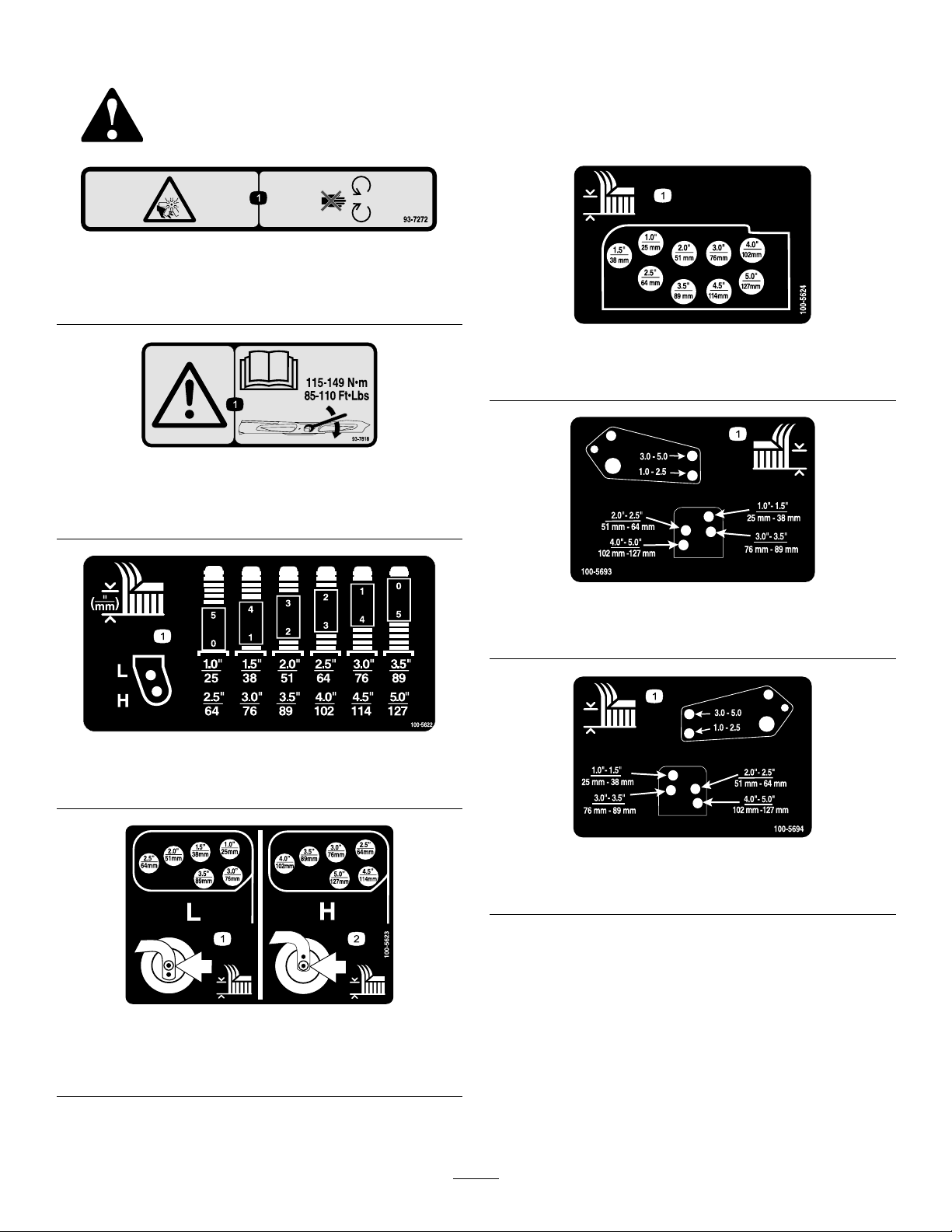
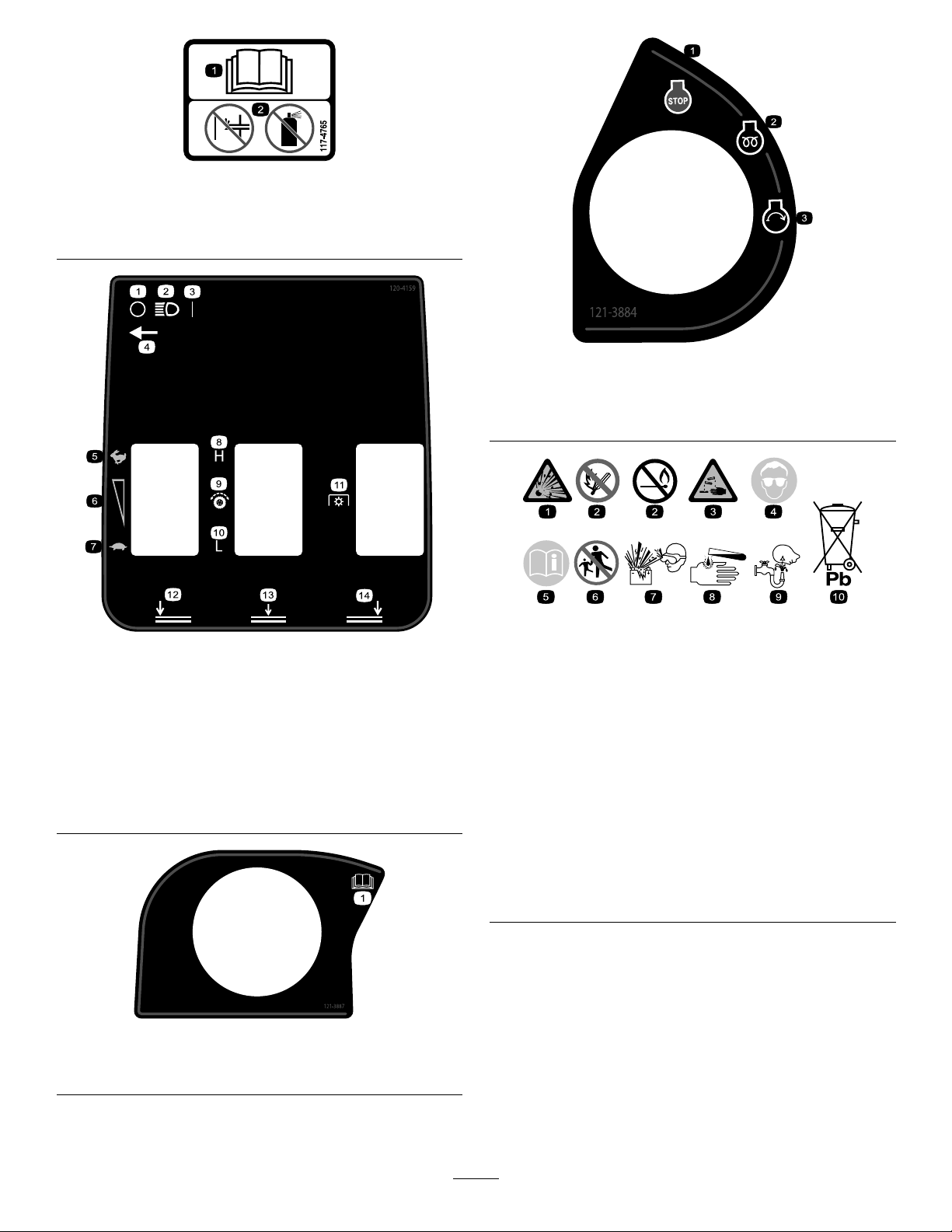
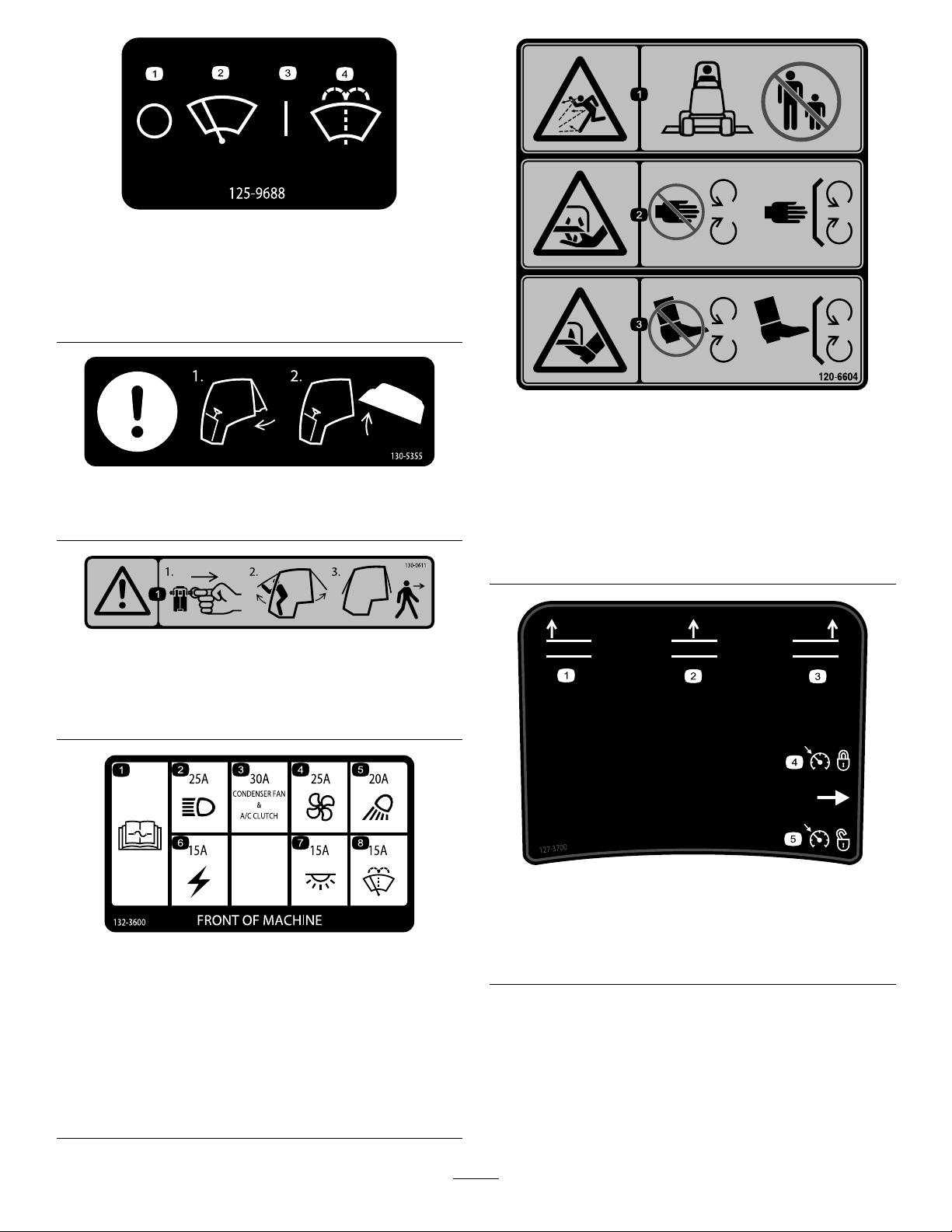
SafetyandInstructionalDecals
Safetydecalsandinstructionsareeasilyvisibletotheoperatorandarelocatednearanyarea
ofpotentialdanger.Replaceanydecalthatisdamagedormissing.
93-7272
1.Cutting/dismembermenthazard;fan—stayawayfrom
movingparts.
93-7818
1.Warning—readtheOperator'sManualforinstructionson
torquingthebladebolt/nutto115-149N∙m(85-110ft-lb).
decal93-7272
decal100-5624
100-5624
1.Height-of-cutadjustment
decal93-7818
1.Height-of-cutadjustment
decal100-5693
100-5693
1.Height-of-cutadjustment
decal100-5622
100-5622
decal100-5694
100-5694
1.Height-of-cutadjustment
decal100-5623
100-5623
1.Lowheight-of-cut
adjustment
2.Highheight-of-cut
adjustment
5
1.Height-of-cutadjustment
decal104-3578
104-3578
1.Enginecoolantunder
pressure.
2.Explosionhazard—read
theOperator'sManual.
decal104-3579
106-6755
3.Warning—donottouchthe
hotsurface.
4.Warning—readthe
Operator'sManual.
decal106-6755
104-3579
1.Lowheight-of-cut
adjustment
2.Highheight-of-cut
adjustment
100-6578
1.Entanglementhazard,belt—donotoperatethemachine
withtheshieldsorguardsremoved;alwayskeeptheshields
andguardsinplace;stayawayfrommovingparts.
106-6754
decal114-0846
114-0846
decal100-6578
decal106-6754
1.ReadtheOperator’sManualforinformationonstartingthe
engine—1)Settoneutral;2)Engagethebrake;3)Setthe
enginespeedtoslow;4)Turntheignitionkeytopreheat;5)
Turntheignitionkeytostarttheengine.
2.ReadtheOperator’sManualforinformationonshuttingof
theengine—1)Settheenginespeedtoslow;2)Disengage
thedeck;3)Locktheparkingbrake;4)Wait5minutes;5)
Turntheignitionkeytoshutoffengine;6)Removethekey
fromtheignition.
3.ReadtheOperator’sManual.
4.PulltheknobouttoengagethePTO.
5.PushtheknobintodisengagethePTO.
6.RaisethedeckstogotoHrange.
1.Warning—donottouchthehotsurface.
2.Cutting/dismembermenthazard,fanandentanglement
hazard,belt—stayawayfrommovingparts.
decal117-2718
117-2718
6
117-4765
1.ReadtheOperator'sManual.
2.Donotusestartingaids.
120-4159
1.Off
2.Lights9.Tractiondrive
3.On
4.Light-switchlocation
5.Fast
6.Variable-speedadjustment13.Lower,centerdeck
7.Slow
8.High
10.Low
11.Powertakeoff(PTO)
12.Lower,leftdeck
14.Lower,rightdeck
decal117-4765
decal121-3884
121–3884
1.Enginestop3.Enginestart
2.Enginepreheat
decalbatterysymbols
decal120-4159
Someorallofthesesymbolsareonyourbattery
1.Explosionhazard
2.Nore,opename,orsmoking
3.Causticliquid/chemicalburnhazard
4.Weareyeprotection.
5.ReadtheOperator'sManual.
6.Keepbystandersasafedistanceawayfromthebattery .
7.Weareyeprotection;explosivegasescancauseblindness
andotherinjuries.
8.Batteryacidcancauseblindnessorsevereburns.
9.Flusheyesimmediatelywithwaterandgetmedicalhelp
fast.
10.Containslead;donotdiscard
BatterySymbols
121–3887
1.ReadtheOperator’sManual.
decal121-3887
7
125-9688
ModelwithCabOnly
1.Windshieldwipers(off)3.Windshieldwipers(on)
2.Windshieldwipers
4.Spraywindshieldwasher
uid
130-5355
1.Closetherearwindow.
2.Raisethehood.
130-0611
ModelwithCabOnly
decal125-9688
decal130-5355
decal130-0611
decal120-6604
120-6604
1.Thrownobjecthazard—keepbystandersawayfromthe
machine.
2.Cutting/dismembermenthazardofhand,mower
blade—stayawayfrommovingparts,keepallguardsand
shieldsinplace.
3.Cutting/dismembermenthazardoffoot,mowerblade—stay
awayfrommovingparts,keepallguardsandshieldsin
place.
1.Warning—1)Removethepin;2)Raisethedoors;3)Exit
thecab.
132-3600
ModelwithCabOnly
1.ReadtheOperator's
Manualformore
informationonfuses.
2.Headlight(25A)6.Auxiliarypower(15A)
3.CondenserfanandA/C
clutch(30A)
4.Fan(25A)8.Windshieldwipers(15A)
5.Workinglight(20A)
7.Cablight(15A)
decal127-3700
127-3700
1.Raisetheleftdeck.
decal132-3600
2.Raisethecenterdeck.5.Unlocktheenginespeed.
3.Raisetherightdeck.
4.Locktheenginespeed.
8
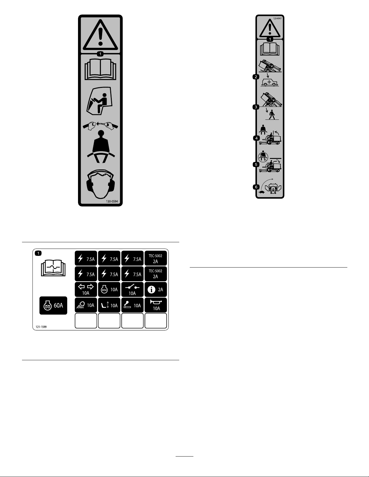
130-0594
1.Warning—readtheOperator’sManual;whensittinginthe
cab,alwayswearaseatbelt;wearhearingprotection.
121-1599
1.ReadtheOperator’sManualforinformationonfuses.
decal120-8947
decal130-0594
1.Warning—readthe
Operator’sManual.
2.Thereisnorollover
protectionwhentheroll
120-8947
4.Iftherollbarisraised,
weartheseatbelt.
5.Iftherollbarislowered,
donotweartheseatbelt.
barisdown.
3.Thereisrolloverprotection
6.Driveslowlywhenturning.
whentherollbarisup.
decal121-1599
9
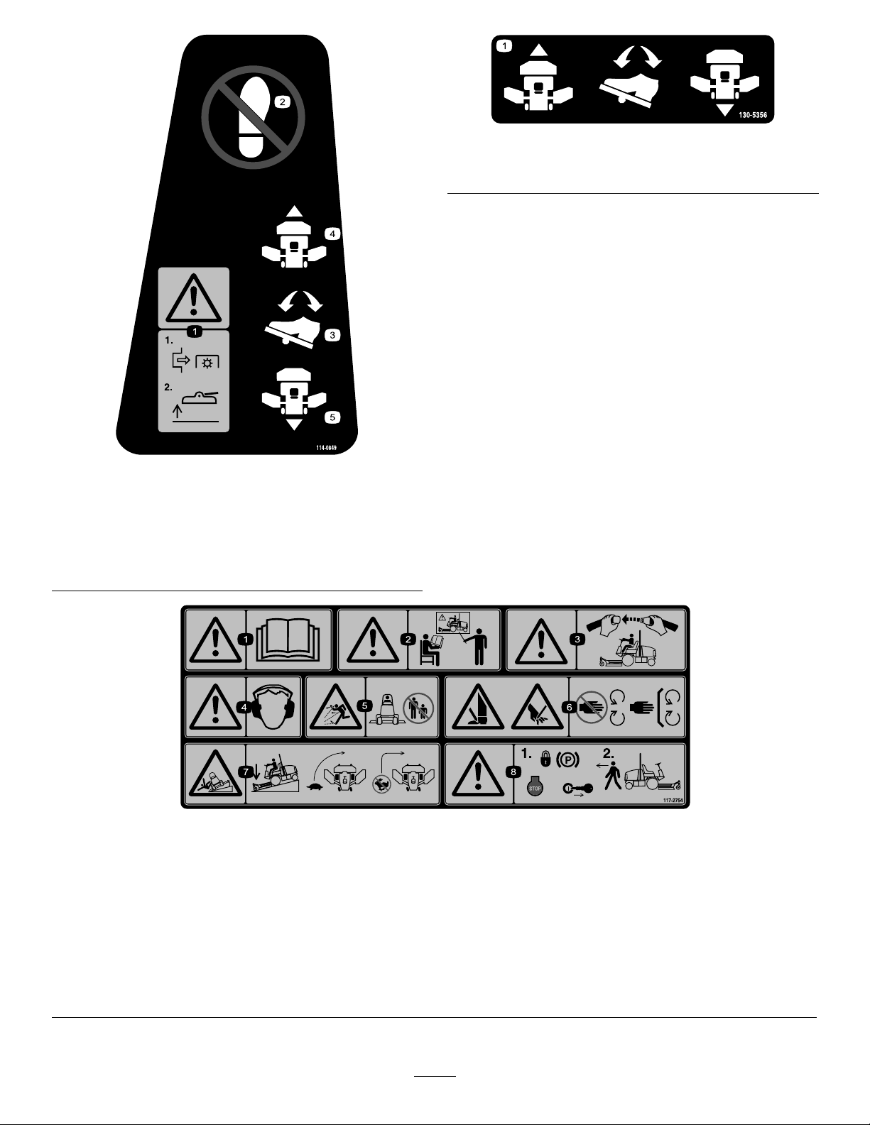
decal130-5356
130-5356
1.Usethefootpedaltomoveforwardorinreverse.
decal114-0849
114-0849
1.Warning—1)Disengage
4.Forwarddirection
thePTO;2)Raisethedeck
2.Donotplaceyourfoot
5.Reversedirection
here.
3.Directionpedal
117-2754
1.Warning—readtheOperator'sManual.
2.Warning—donotoperatethismachineunlessyouaretrained.
3.Warning—weartheseatbeltwhenseatedintheoperator'sposition.
4.Warning—wearhearingprotection.
5.Thrownobjecthazard—keepbystandersasafedistanceawayfromthemachine.
6.Cuttinghazardofhandorfoot—stayawayfrommovingparts;keepallguardsinplace.
7.Tippinghazard—lowerthecuttingunitwhendrivingdownslopes;slowmachinebeforeturning,donotturnathighspeeds
8.Warning—locktheparkingbrake,shutofftheengine,andremovethekeyfromtheignitionbeforeleavingthemachine.
decal117-2754
10

117-2766
(AfxoverPartNo.117-2754forCE*)
*ThissafetydecalincludesaslopewarningrequiredonthemachineforcompliancetotheEuropeanLawnMowerSafetyStandardENISO5395:2013.Theconservative
maximumslopeanglesindicatedforoperationofthismachineareprescribedbyandrequiredbythisstandard.
Thismachinecomplieswiththeindustry
standardstabilitytestinthestaticlateralandlongitudinaltestswiththemaximumrecommendedslopeindicatedonthe
decal.ReviewtheinstructionsforoperatingthemachineonslopesintheOperator'sManualandtheconditionsinwhich
themachineisbeingoperatedtodeterminewhetherthemachinecanbeoperatedintheconditionsonthatdayandatthat
site.Changesintheterraincanresultinachangeinslopeoperationforthemachine.Ifpossible,keepthe
cuttingunitsloweredtothegroundwhileoperatingthemachineonslopes.Raisingthecuttingunitswhile
operatingonslopescancausethemachinetobecomeunstable.
1.Warning—readtheOperator'sManual.
2.Warning—donotoperatethismachineunlessyouaretrained.
3.Warning—weartheseatbeltwhenseatedintheoperator'sposition.
4.Warning—wearhearingprotection.
5.Thrownobjecthazard—keepbystandersasafedistanceawayfromthemachine.
6.Cuttinghazardofhandorfoot—stayawayfrommovingparts;keepallguardsinplace.
7.Tippinghazard—lowerthecuttingunitwhendrivingdownslopes;donotoperatemachineonslopesgreaterthan15degrees.
8.Warning—locktheparkingbrake,shutofftheengine,andremovethekeyfromtheignitionbeforeleavingthemachine.
decal117-2766
11
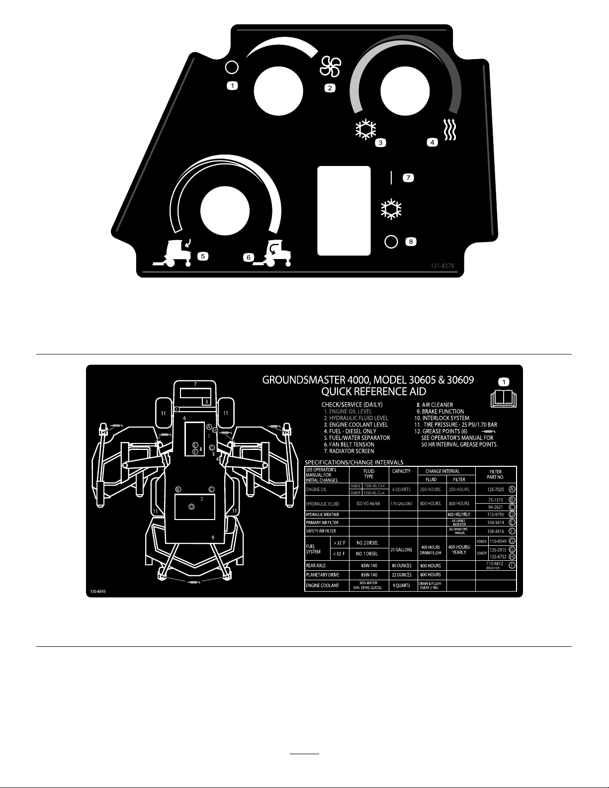
121-8378
ModelwithCabOnly
decal121-8378
1.Fan(off)3.Coldair
2.Fan(onfull)
4.Hotair6.Internalair
130-6043
5.Externalair
7.Airconditioner(off)
8.Airconditioner(on)
decal130-6043
1.ReadtheOperator’sManual.
12

1.Slow-movingvehicle
decal120-0250
120-0250
13
1.ReadtheOperator’sManual.
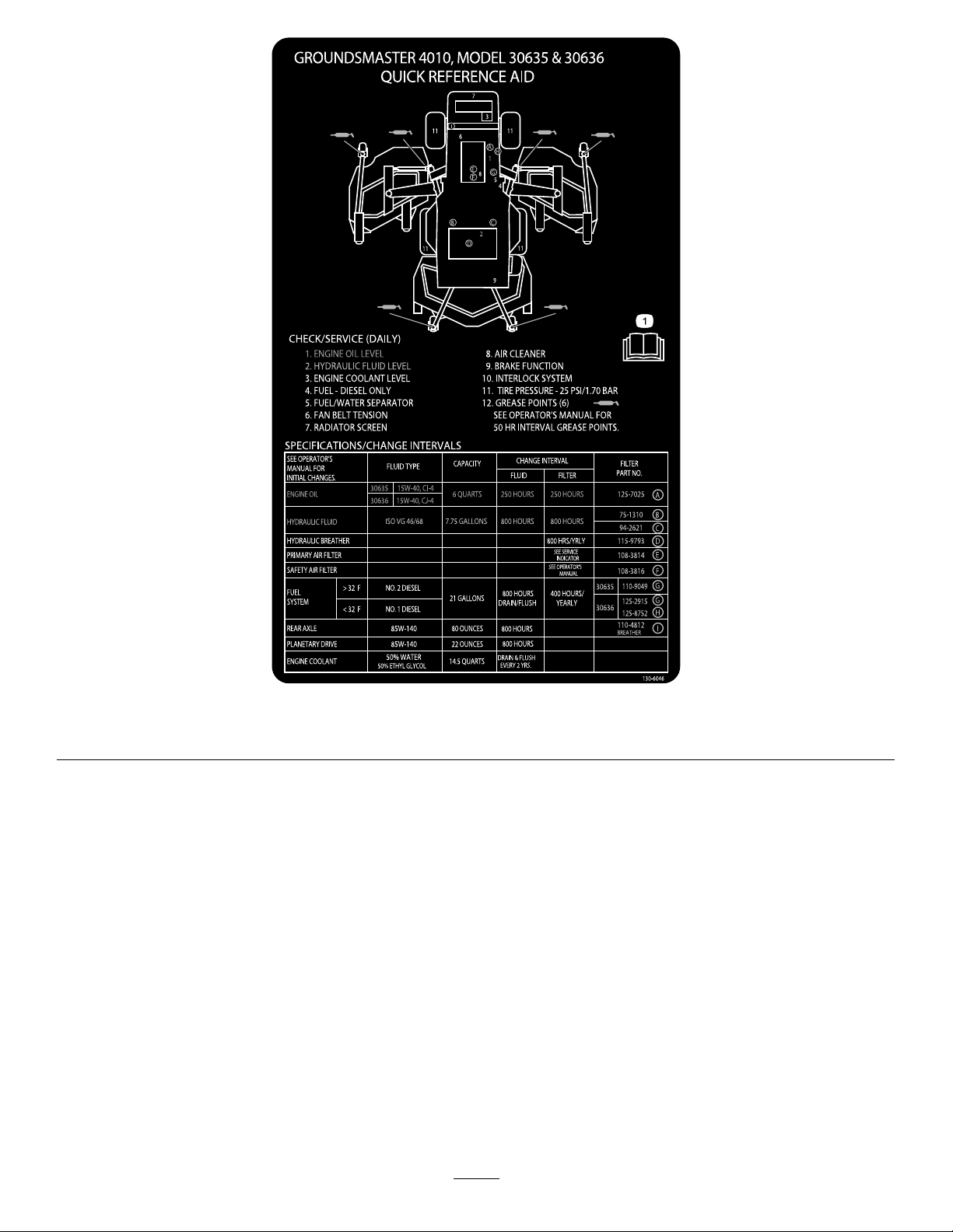
decal130-6046
130-6046
14

Setup
LooseParts
Usethechartbelowtoverifythatallpartshavebeenshipped.
ProcedureDescription
1
2
Nopartsrequired
Warningdecal1Replacethewarningdecal.
MediaandAdditionalParts
Description
Operator'sManual
Engineowner’smanual1
PartsCatalog
Operatortrainingmaterials
DeclarationofConformity
Note:Determinetheleftandrightsidesofthe
machinefromthenormaloperatingposition.
Qty.
Qty.
–
1
1
1
1
Reviewbeforeoperatingthemachine.
Usetoreferenceengineinformation.
Usetoreferencepartnumbers.
Reviewbeforeoperatingthemachine.
Greasethemachine.
Use
Use
2
1
GreasingtheMachine
NoPartsRequired
Procedure
Beforeyouoperatethemachine,greaseittoensure
properlubricatingcharacteristics;refertoGreasing
theBearingsandBushings(page57).Failureto
properlygreasethemachinewillresultinpremature
failureofcriticalparts.
ReplacingtheWarning Decal
ForCEModelsOnly
Partsneededforthisprocedure:
1Warningdecal
Procedure
OnmachinesrequiringEuropeanCEcompliance,
replacethewarningdecalPartNo.117-2754withthe
warningdecalPartNo.117-2766.
15
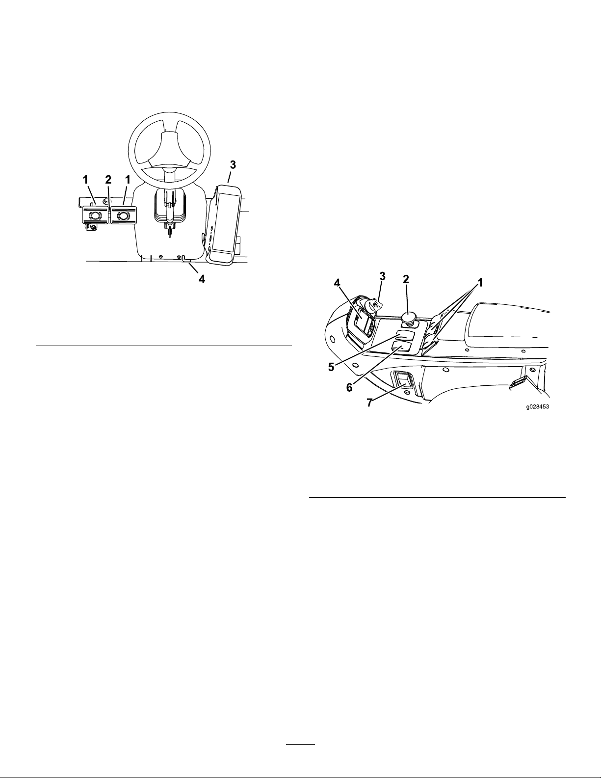
ProductOverview
g028453
1
2
3
4
5
6
7
theparking-brakelatchout.T oreleasetheparking
brake,pressbothpedalsuntiltheparking-brakelatch
retracts.
Controls
Note:Determinetheleftandrightsidesofthe
machinefromthenormaloperatingposition.
Figure3
1.Brakepedals3.Tractionpedal
2.Pedal-lockinglatch4.Tilt-steeringlever
Hazard-LightSwitch
Pressthehazard-lightswitchtoactivatethehazard
lights(Figure3).
Turn-SignalSwitch
Presstheleftsideoftheturn-signalswitchtoactivate
theleft-turnsignalandtherightsideoftheswitchto
activatetheright-turnsignal(Figure3).
KeySwitch
Thekeyswitch(Figure4)has3positions:OFF,
ON/PREHEAT,andSTART.
g196908
TractionPedal
Tostopthemachine,reduceyourfootpressureon
thetractionpedalandallowittoreturntothecenter
position(Figure3).
BrakePedals
Thereare2footpedalsthatoperateindividualwheel
brakesforturningassistance,parking,andtoaidin
betterside-hilltraction.Alatchconnectsthepedals
forparking-brakeoperationandtransport(Figure3).
Pedal-LockingLatch
Thepedal-lockinglatchconnectsthepedalstogether
toengagetheparkingbrake(Figure3).
Tilt-SteeringLever
Pressthetilt-steeringleverdowntotiltthesteering
wheeltothedesiredposition,thenreleasethelever
tolocktheadjustment(Figure3).
Parking-BrakeLatch
Aknobontheleftsideoftheconsoleactuatesthe
parking-brakelock(Figure3).
Toengagetheparkingbrake,connectthepedalswith
thelockinglatch,pushdownonbothpedals,andpull
Figure4
1.Liftswitches
2.PTOswitch
3.Keyswitch
4.InfoCenter
5.Hi—Lospeedcontrol
6.Engine-speedswitch
7.Lightswitch(optional)
Engine-SpeedSwitch
Theengine-speedswitchhas2modestochangethe
enginespeed(Figure4).
Bymomentarilytappingtheswitch,theengine
speedcanbeincreasedordecreasedin100-rpm
increments.Byholdingtheswitchdowntheenginewill
automaticallymovetoHIGHorLOWIDLE,depending
onwhichswitchisdepressed.
PTOSwitch
ThePTOswitchhas2positions:OUT(START)and
IN(STOP).PullthePTObuttonouttoengagethe
mower-deckblades.Pushthebuttonintodisengage
themower-deckblades(Figure4).
g028453
16
High—LowSpeed-ControlSwitch
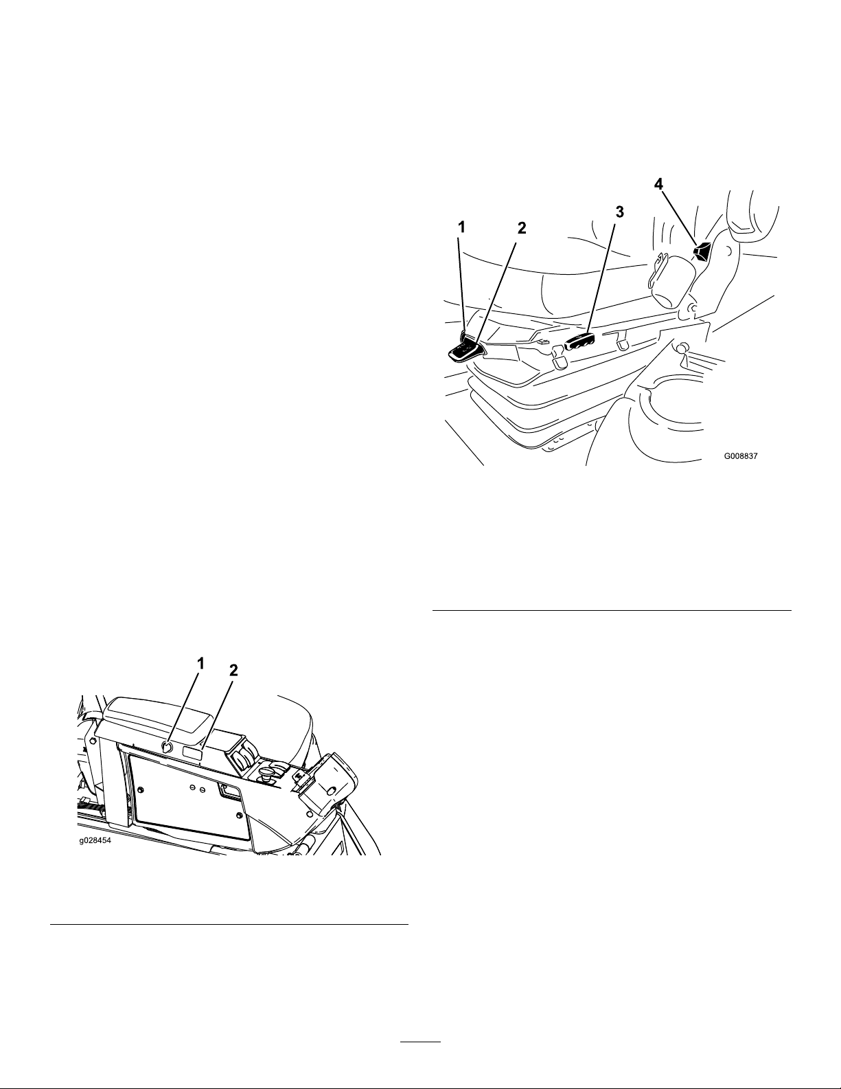
g028454
1
2
SeatAdjustments
TheHi-Lospeed-controlswitchallowsthespeed
rangetoincreasefortransportofthemachine(Figure
4).
Mowerdecksdonotoperateinhighrange.Toswitch
betweentheHIGHandLOWrange,raisethedecks,
disengagethePTOandthecruisecontrol,movethe
tractionpedalintheNEUTRALposition,andhavethe
machinemoveataslowspeed.
LiftSwitches
Theliftswitchesraiseandlowerthemowerdecks
(Figure4).Presstheswitchesforwardtolowerthe
mowerdecksandrearwardtoraisethemowerdecks.
Whenstartingthemachine,withthemowerdecksin
thedownposition,presstheliftswitchdowntoallow
themowerdeckstooatandmow.
Note:Thedecksdonotlowerwhileinthehigh-speed
rangeandtheydonotraiseorlowerifyouareoutof
theseatwhiletheengineisrunning.Also,thedecks
lowerwiththekeyintheONpositionandyouarein
theseat.
Seat-AdjustmentLever
Movetheseat-adjustmentleveronthesideofthe
seatoutward,slidetheseattothedesiredposition,
andreleasethelevertolocktheseatintoposition
(Figure6).
Cruise-ControlSwitch
Thecruise-controlswitchlocksinthepedalposition
tomaintainthedesiredgroundspeed(Figure5).
Pressingtherearoftheswitchturnsoffthecruise
control,themiddlepositionoftheswitchenablesthe
cruise-controlfunction,andthefrontoftheswitchsets
thedesiredgroundspeed.
Note:Pressingeitherbrakepedalormovingthe
tractionpedalintothereverseposition,for1second,
alsodisengagesthepedalposition.
Figure5
1.Power-pointswitch
2.Cruise-controlswitch
g008837
Figure6
1.Weightgauge
2.Weight-adjustmentlever5.Armrest-adjustmentknob
3.Seat-adjustmentlever
Armrest-AdjustmentKnob
4.Seat-backadjustment
lever
(notshown;locatedunder
armrest)
Rotatetheknobtoadjustthearmrestangle(Figure6).
Seat-Back-AdjustmentLever
Movethelevertoadjusttheseat-backangle(Figure
6).
WeightGauge
Theweightgaugeindicateswhentheseatisadjusted
totheweightoftheoperator(Figure6).Adjustthe
g028454
heightbypositioningthesuspensionwithintherange
ofthegreenregion.
Weight-AdjustmentLever
Power-PointSwitch
Usethepower-pointswitchtopoweroptionalelectrical
accessories(Figure5).
Usethislevertoadjusttotheproperweightofthe
operator(Figure6).Pullupthelevertoincrease
theairpressureandpushdowntodecreasetheair
pressure.Theproperadjustmentiscorrectwhenthe
weightgaugeisinthegreenregion.
17
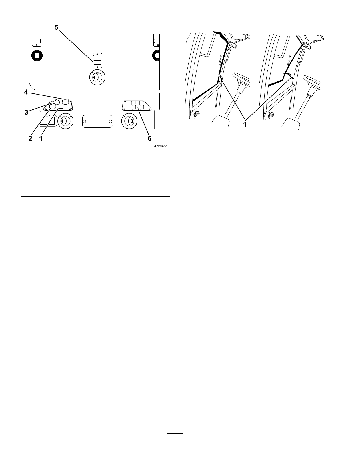
CabControls
outanddownonthelatchtocloseandsecurethe
windshield.
g196911
Figure8
Figure7
1.Air-conditioningswitch4.Temperaturecontrol
2.Air-recirculationcontrol5.Windshield-wiperswitch
3.Fancontrol
Air-RecirculationControl
6.Blankswitchesforoptional
kits
Theair-recirculationcontrolsetsthecabtoeither
recirculatetheairinthecabinortodrawairintothe
cabinfromoutside(Figure7).
•Setittorecirculatetheairwhenusingthe
air-conditioning.
•Setittodrawairinwhenusingtheheaterorfan.
FanControl
Rotatethefancontrolknobtoregulatethespeedof
thefan(Figure7).
TemperatureControl
g032672
1.Windshieldlatch
RearWindowLatch
Liftupthelatchestoopentherearwindow.Pressin
thelatchtolockthewindowopen.Pulloutanddown
onthelatchtocloseandsecurethewindow(Figure8).
Important:Youmustclosetherearwindow
beforeyouopenthehood;otherwise,damage
mayoccur.
Rotatethetemperaturecontrolknobtoregulatethe
airtemperatureinthecab(Figure7).
Windshield-WiperSwitch
Usethisswitchtoturnthewindshieldwipersonor
off(Figure7).
AirConditioningSwitch
Usethisswitchtoturntheairconditioningonoroff
(Figure7).
WindshieldLatch
Liftupthelatchestoopenthewindshield(Figure8).
Pressinthelatchtolockthewindshieldopen.Pull
18
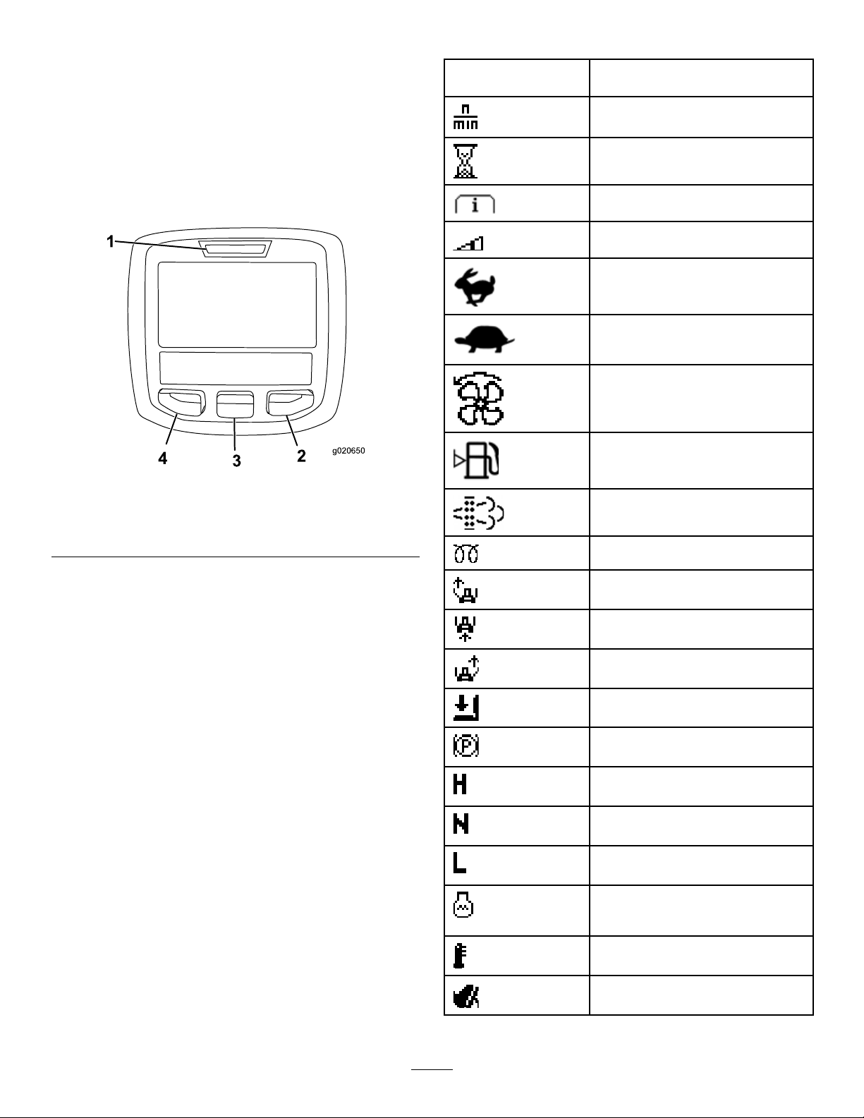
UsingtheInfoCenterControl
1
g020650
2
3
4
TORO
InfoCenterIconDescription
TheInfoCenterLCDdisplayshowsinformationabout
yourmachine,suchastheoperatingstatus,various
diagnosticsandotherinformationaboutthemachine
(Figure9).Thereisasplashscreenandmain
informationscreenoftheInfoCenter.Y oucanswitch
betweenthesplashscreenandmaininformation
screenatanytimebypressinganyoftheInfoCenter
buttonsandthenselectingtheappropriatedirectional
arrow.
Figure9
1.Indicatorlight3.Middlebutton
2.Rightbutton
4.Leftbutton
SERVICEDUE
g020650
Indicateswhenscheduledservice
shouldbeperformed
Enginerpm/status—indicatesthe
enginerpm
Hourmeter
Infoicon
Setsthemaximumtractionspeed
Fast
Slow
FanReversal—indicateswhenthe
fanisreversed
Fuellevel
Stationaryregenerationrequired
Airintakeheaterisactive
•LeftButton,MenuAccess/BackButton—pressthis
Raisetheleftdeck
buttontoaccesstheInfoCentermenus.Youcan
useittoexitanymenuthatyouarecurrentlyusing.
Raisethecenterdeck
•MiddleButton—usethisbuttontoscrolldown
menus.
Raisetherightdeck
•RightButton—usethisbuttontoopenamenu
wherearightarrowindicatesadditionalcontent.
Operatormustsitinseat
•Beeper—activatedwhenloweringthedecksorfor
advisoriesandfaults.
Note:Thepurposeofeachbuttonmaychange
dependingonwhatisrequiredatthetime.Each
buttonislabeledwithanicondisplayingitscurrent
function.
ParkingBrakeIndicator—indicates
whentheparkingbrakeison
IdentiestherangeasHigh
Neutral
IdentiestherangeasLow
CoolantTemperature-indicatesthe
enginecoolanttemperatureineither
°Cor°F
Temperature(hot)
TractionorTractionPedal
19
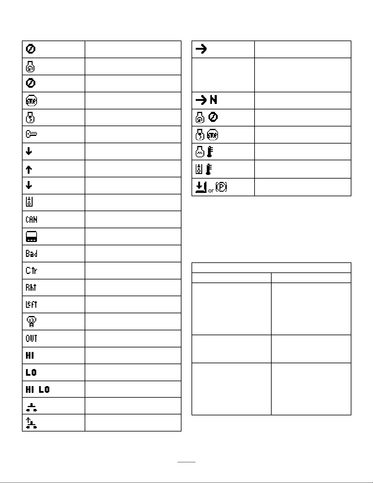
InfoCenterIconDescription(cont'd.)
InfoCenterIconDescription(cont'd.)
Deniedornotallowed
EngineStart
PTO—indicatesthatthePTOison
Stoporshutdown
Engine
Keyswitch
Indicateswhenthemowerdecksare
beinglowered
Indicateswhenthemowerdecksare
beingraised
PINcode
Hydraulic-OilT emperature—indicates
thehydraulic-oiltemperature
CANbus
Operatorshouldchangetothe
indicatedstate
Symbolsareoften
combinedtoform
sentences.Some
examplesareshown
below
Operatorshouldputthemachinein
neutral
Enginestartdenied
Engineshutdown
Enginecoolantistoohot
Hydraulicuidistoohot
Sitdownorengagetheparkingbrake
UsingtheMenus
ToaccesstheInfoCentermenusystem,pressthe
InfoCenter
menuaccessbuttonwhileatthemainscreen.This
willbringyoutothemainmenu.Refertothefollowing
Badorfailed
tablesforasynopsisoftheoptionsavailablefrom
themenus:
Center
Right
Left
Bulb
OutputofTECcontrollerorcontrol
wireinharness
High:over-allowedrange
Low:under-allowedrange
Outofrange
/
Switch
Operatormustreleasetheswitch
MainMenu
MenuItemDescription
FaultsTheFaultsmenucontains
alistoftherecentmachine
faults.RefertotheService
ManualoryourAuthorized
ToroDistributorformore
informationontheFaults
menuandtheinformation
containedthere.
ServiceTheServicemenucontains
informationonthemachine
suchashoursofuseandother
similarnumbers.
DiagnosticsTheDiagnosticsmenu
displaysthestateofeach
machineswitch,sensorand
controloutput.Y oucanuse
thistotroubleshootcertain
issuesasitwillquicklytellyou
whichmachinecontrolsareon
andwhichareoff.
20

SettingsTheSettingsmenuallows
AboutTheAboutmenuliststhe
Service
MenuItemDescription
Hours
CountsListsthenumberofpreheats
Diagnostics
MenuItemDescription
EngineRun
GlowplugsIndicatesifthefollowingitems
Fan
Settings
MenuItemDescription
Units
Language
LCDBacklightControlsthebrightnessofthe
LCDContrastControlsthecontrastofthe
ProtectedMenusAllowsapersonauthorized
AutoIdle
youtocustomizeandmodify
congurationvariablesonthe
InfoCenterdisplay.
modelnumber,serialnumber,
andsoftwareversionofyour
machine.
Liststhetotalnumberofhours
thatthemachine,engineand
fanhavebeenon,aswellas
thenumberofhoursthatthe
machinehasbeentransported
andoverheated
andstartsthatthemachine
hasexperienced
RefertotheService
ManualoryourAuthorized
ToroDistributorformore
informationontheEngine
Runmenuandtheinformation
containedthere.
areactive:Keystart,timeout
limited,andglowplugs
Indicatesifthefanisactive
inthefollowinginstances:
Enginehightemp,oilhigh
temp,engineorhydraulichigh
temp,andfanon
Controlstheunitsusedonthe
InfoCenter;themenuchoices
areEnglishorMetric
Controlsthelanguageused
ontheInfoCenter*
LCDdisplay
LCDdisplay
byyourcompanywiththe
PINcodetoaccessprotected
menus.
Controlstheamountoftime
allowedbeforeidlingthe
enginewhenthemachineis
notinuse
MowSpeedControlsthemaximumspeed
TransSpeedControlsthemaximumspeed
SmartPowerSmartPowerprevents
whileinmow(lowrange)
whileintransport(highrange)
boggingdowninheavyturfby
automaticallycontrollingthe
machinespeedandoptimizing
cuttingperformance.
*Only"operator-faced"textistranslated.Faults,
Service,andDiagnosticsscreensare"service-faced."
Titleswillbeintheselectedlanguage,butmenuitems
areinEnglish.
About
MenuItemDescription
Model
SNListstheserialnumberofthe
MachineControllerRevisionListsthesoftwarerevisionof
InfoCenterRevisionListsthesoftwarerevisionof
CANBus
Liststhemodelnumberofthe
machine
machine
themastercontroller
theInfoCenter
Liststhemachine
communicationbusstatus
ProtectedMenus
Thereare4operatingcongurationsettingsthatare
adjustablewithintheSettingsMenuoftheInfoCenter:
autoidletimedelay,maximummowinggroundspeed,
maximumtransportgroundspeed,andSmartPower.
ThesesettingsareintheProtectedMenu.
AccessingProtectedMenus
Note:ThefactorydefaultPINcodeforyoumachine
iseither0000or1234.
IfyouchangedthePINcodeandforgotthe
code,contactyourAuthorizedToroDistributorfor
assistance.
1.FromtheMAINMENU,usethecenterbuttonto
scrolldowntotheSETTINGSMENUandpressthe
rightbutton(Figure10).
21
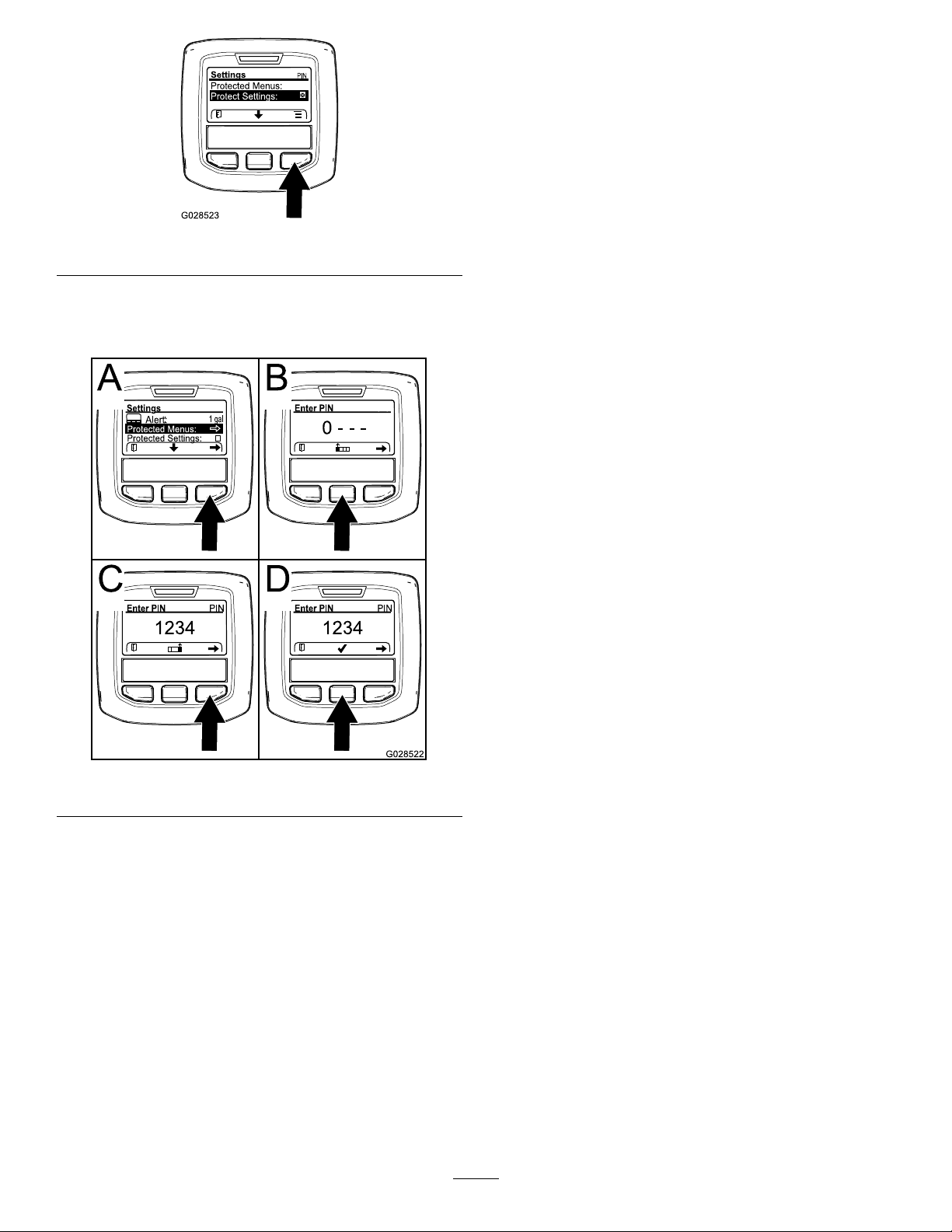
Figure10
2.IntheSETTINGSMENU,usethecenterbuttonto
scrolldowntothePROTECTEDMENUandpress
therightbutton(Figure11A).
Note:RotatethekeyswitchtotheOFFpositionand
thentotheONpositionlockstheprotectedmenu.
Youhavetheabilitytoviewandchangethesettingsin
theProtectedMenu.OnceyouaccesstheProtected
Menu,scrolldowntoProtectSettingsoption.Usethe
rightbuttontochangethesetting.SettingtheProtect
SettingstoOFFallowsyoutoviewandchangethe
settingsintheProtectedMenuwithoutenteringthe
g028523
PINcode.SettingtheProtectSettingstoONhidesthe
protectedoptionsandrequiresyoutoenterthePIN
codetochangethesettingintheProtectedMenu.
AfteryousetthePINcode,rotatethekeyswitchOFF
andbacktotheONpositiontoenableandsavethis
feature.
SettingtheAutoIdle
•IntheSettingsMenu,scrolldowntoAutoIdle.
•Presstherightbuttontochangetheautoidletime
betweenOff,8S,10S,15S,20S,and30S.
SettingtheMaximumAllowed
Figure11
3.T oenterthePINcode,pressthecenterbutton
untilthecorrectrstdigitappears,thenpress
therightbuttontomoveontothenextdigit
(Figure11BandFigure1 1C).Repeatthisstep
untilthelastdigitisenteredandpresstheright
buttononcemore.
4.PressthemiddlebuttontoenterthePINcode
(Figure11D).
WaituntiltheredindicatorlightoftheInfoCenter
illuminates.
MowSpeed
•IntheSettingsMenu,ScrolldowntoMowSpeed
andpresstherightbutton.
•Usetherightbuttontoincreasethemaxfullmow
speed(50%,75%,or100%).
•Usethecenterbuttontodecreasethemaxfull
mowspeed(50%,75%,or100%).
•Presstheleftbuttontoexit.
SettingtheMaximumAllowed
g028522
TransportSpeed
•IntheSettingsMenu,scrolldowntoTransport
Speedandpresstherightbutton.
•Usetherightbuttontoincreasethemaxtransport
speed(50%,75%,or100%).
•Usethecenterbuttontodecreasethemax
transportspeed(50%,75%,or100%).
•Presstheleftbuttontoexit.
WhennishedwiththeProtectedMenu,presstheleft
buttontoexittotheMainMenu,thenpresstheleft
buttontoexittotheRunMenu.
Note:IftheInfoCenteracceptsthePINcode
andtheprotectedmenuisunlocked,theword
“PIN”displaysintheupperrightcornerofthe
screen.
22
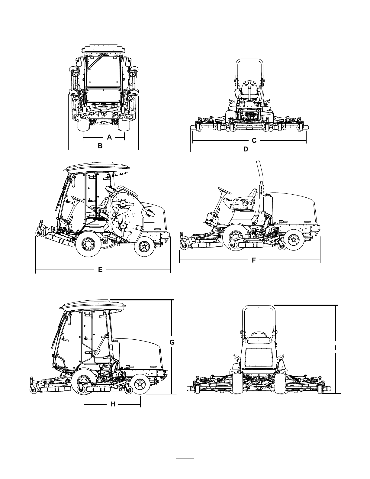
Specications
Note:Specicationsanddesignaresubjecttochangewithoutnotice.
Figure12
g197050
23

DescriptionFigure12
Heightwithcab
Heightwithrollbar
Overalllength
Lengthforstorageortransport
Widthofcut
overall
frontcuttingunit157cm(62inches)
sidecuttingunit
frontandonesidecuttingunit246cm(97inches)
Overallwidth
cuttingunitsdown
cuttingunitsup(transportposition)
Wheelbase
Wheeltread(tirecentertocenter)
front
rear
Groundclearance17cm(6-1/2inches)
Netweightwithcab
Netweightwithrollbar
reference
G237cm(93-1/2inches)
I
F
E
C
D
B
H
A
J
DimensionorWeight
218cm(86inches)
342cm(135inches)
338cm(133inches)
335cm(132inches)
107cm(42inches)
345cm(136inches)
183cm(73inches)
141cm(55-1/2inches)
114cm(45inches)
107cm(42inches)
2159kg(4,759lb)
2159kg(4,759lb)
Attachments/Accessories
AselectionofToroapprovedattachmentsand
accessoriesisavailableforusewiththemachineto
enhanceandexpanditscapabilities.Contactyour
AuthorizedServiceDealerorDistributororgoto
www.T oro.comforalistofallapprovedattachments
andaccessories.
Operation
Note:Determinetheleftandrightsidesofthe
machinefromthenormaloperatingposition.
BeforeOperation
BeforeOperationSafety
GeneralSafety
•Neverallowchildrenoruntrainedpeopleto
operateorservicethemachine.Localregulations
mayrestricttheageoftheoperator.Theowner
isresponsiblefortrainingalloperatorsand
mechanics.
•Becomefamiliarwiththesafeoperationofthe
equipment,operatorcontrols,andsafetysigns.
•Knowhowtostopthemachineandenginequickly.
•Checkthatoperator-presencecontrols,safety
switches,andshieldsareattachedandfunctioning
properly.Donotoperatethemachineunlessthey
arefunctioningproperly.
24

•Beforemowing,alwaysinspectthemachineto
ensurethattheblades,bladebolts,andcutting
assembliesareingoodworkingcondition.
Replacewornordamagedbladesandboltsinsets
topreservebalance.
•Inspecttheareawhereyouwillusethemachine
andremoveallobjectsthatthemachinecould
throw.
FuelSpecication
Important:Useonlyultra-lowsulphurdiesel
fuel.Fuelwithhigherratesofsulfurdegrades
thedieseloxidationcatalyst(DOC),whichcauses
operationalproblemsandshortenstheservicelife
ofenginecomponents.
Failuretoobservethefollowingcautionsmay
damagetheengine.
FuelSafety
•Useextremecareinhandlingfuel.Itisammable
anditsvaporsareexplosive.
•Extinguishallcigarettes,cigars,pipes,andother
sourcesofignition.
•Useonlyanapprovedfuelcontainer.
•Neverremovethefuelcaporllthefueltankwhile
theengineisrunningorhot.
•Neverrefuelthemachineinanenclosedspace.
•Neverstorethemachineorfuelcontainerwhere
thereisanopename,spark,orpilotlight,such
asonawaterheaterorotherappliance.
•Ifyouspillfuel,donotattempttostarttheengine;
avoidcreatinganysourceofignitionuntilthefuel
vaporshavedissipated.
CheckingtheEngine-Oil Level
Beforeyoustarttheengineandusethemachine,
checktheoillevelintheenginecrankcase;referto
CheckingtheEngine-OilLevel(page59).
•Neverusekeroseneorgasolineinsteadofdiesel
fuel.
•Nevermixkeroseneorusedengineoilwiththe
dieselfuel.
•Neverkeepfuelincontainerswithzincplatingon
theinside.
•Donotusefueladditives.
PetroleumDiesel
Cetanerating:45orhigher
Sulfurcontent:Ultra-lowsulfur(<15ppm)
CheckingtheCooling System
Beforeyoustarttheengineandusethemachine,
checkthecoolingsystem;refertoCheckingthe
CoolingSystem(page68).
CheckingtheHydraulic System
Beforeyoustarttheengineandusethemachine,
checkthehydraulicsystem;refertoCheckingthe
HydraulicFluid(page71).
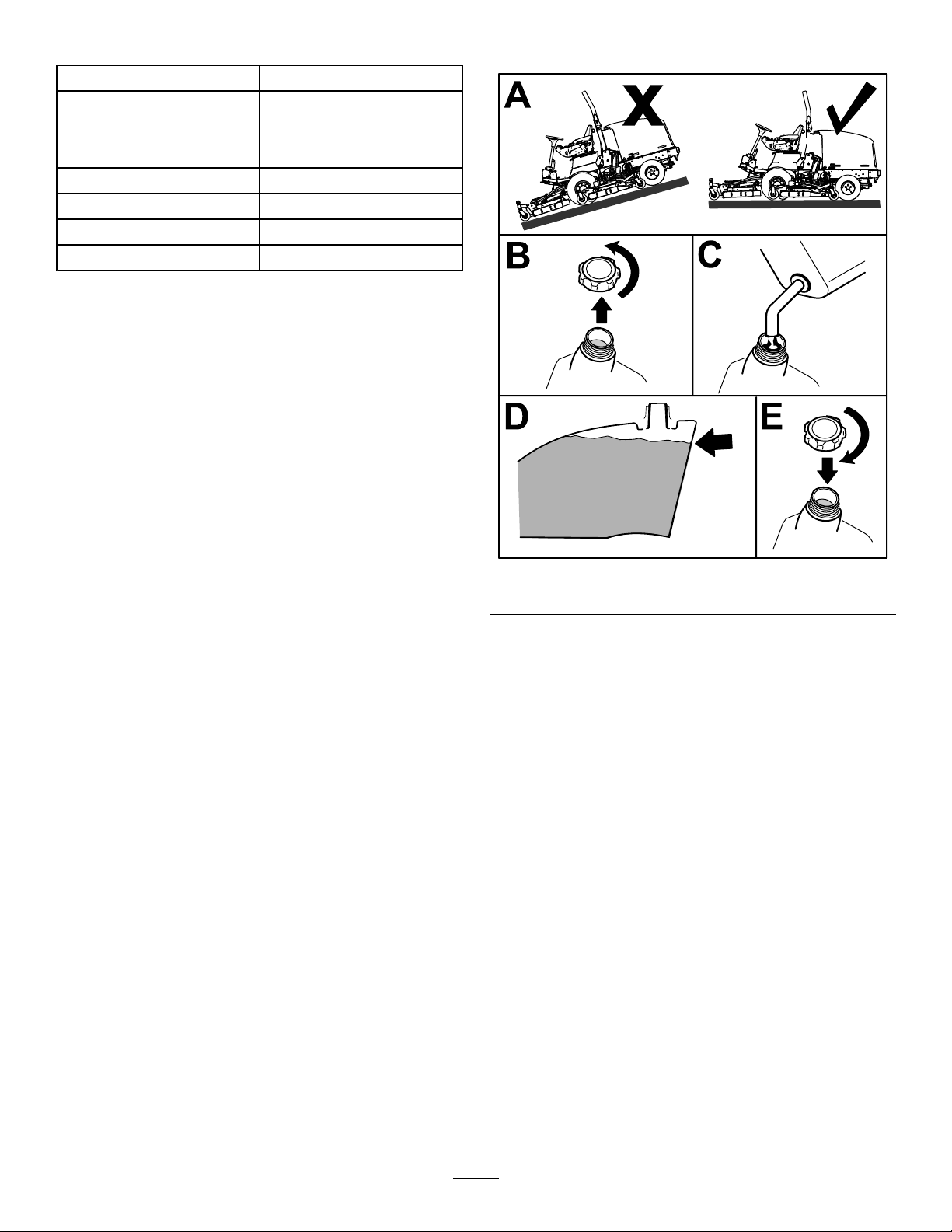
FillingtheFuelTank
FuelTankCapacity
Fueltankcapacity:79L(21USgallons)
25
FuelTable
AddingFuel
Dieselfuelspecication
ASTMD975
No.1-DS15
No.2-DS15
EN590EuropeanUnion
ISO8217DMX
JISK2204GradeNo.2
KSM-2610
Location
USA
International
Japan
Korea
•Useonlyclean,freshdieselfuelorbiodieselfuels.
•Purchasefuelinquantitiesthatcanbeusedwithin
180daystoensurefuelfreshness.
Usesummer-gradedieselfuel(No.2-D)at
temperaturesabove-7°C(20°F)andwinter-grade
fuel(No.1-DorNo.1-D/2-Dblend)belowthat
temperature.
Note:Useofwinter-gradefuelatlowertemperatures
provideslowerashpointandcoldowcharacteristics
whicheasesstartingandreducesfuellterplugging.
Usingsummer-gradefuelabove-7°C(20°F)
contributestowardlongerfuelpumplifeandincreased
powercomparedtowinter-gradefuel.
Biodiesel
g196909
Figure13
Thismachinecanalsouseabiodieselblendedfuelof
uptoB20(20%biodiesel,80%petroleumdiesel).
Sulfurcontent:Ultra-lowsulfur(<15ppm)
Biodieselfuelspecication:ASTMD6751or
EN14214
Blendedfuelspecication:ASTMD975,EN590,
orJISK2204
Important:Thepetroleumdieselportionmust
beultra-lowsulfur.
Observethefollowingprecautions:
•Biodieselblendsmaydamagepaintedsurfaces.
•UseB5(biodieselcontentof5%)orlesserblends
incoldweather.
•Monitorseals,hoses,gasketsincontactwithfuel
astheymaybedegradedovertime.
•Fuellterpluggingmaybeexpectedforatime
afterconvertingtobiodieselblends.
•ContactyourAuthorizedT oroDistributorifyou
wishformoreinformationonbiodiesel.
Fillthetanktoabout6to13mm(1/4to1/2inch)
belowthetopofthetank,notthellerneck,with
Number2-Ddieselfuel.
Note:Ifpossible,llthefueltankaftereachuse;this
willminimizepossiblebuildupofcondensationinside
thefueltank.
26
 Loading...