

Page 1
FormNo.3364-486RevB
g012615
CommercialWalk-BehindMower
FixedDeck,PistolGrip,GearDrivewitha
32in,36inor48inCuttingUnit
ModelNo.30632—SerialNo.310000001andUp
ModelNo.30634—SerialNo.310000001andUp
ModelNo.30638—SerialNo.310000001andUp
ToregisteryourproductordownloadanOperator'sManualorPartsCatalogatnocharge,gotowww.T oro.com.OriginalInstructions(EN)
Page 2
WARNING
CALIFORNIA
Proposition65Warning
Theengineexhaustfromthisproduct
containschemicalsknowntotheStateof
Californiatocausecancer,birthdefects,
orotherreproductiveharm.
Figure1
ThissparkignitionsystemcomplieswithCanadian
ICES-002.
Important:Thisengineisnotequippedwitha
sparkarrestermufer.ItisaviolationofCalifornia
PublicResourceCodeSection4442touseoroperate
theengineonanyforest-covered,brush-covered,or
grass-coveredland.Otherstatesorfederalareas
mayhavesimilarlaws.
Theenclosed
Engine Owner's Man ual
issupplied
forinformationregardingtheUSEnvironmental
ProtectionAgency(EPA)andtheCalifornia
EmissionControlRegulationofemissionsystems,
maintenance,andwarranty.Replacementsmaybe
orderedthroughtheenginemanufacturer.
Introduction
Thisrotary-blade,lawnmowerisintendedtobe
usedbyresidentialhomeownersorprofessional,
hiredoperators.Itisdesignedprimarilyforcutting
grassonwell-maintainedlawnsonresidential
orcommercialproperties.Itisnotdesignedfor
cuttingbrushorforagriculturaluses.
1.Modelandserialnumberlocation
ModelNo.
SerialNo.
Thismanualidentiespotentialhazardsandhassafety
messagesidentiedbythesafetyalertsymbol(Figure2),
whichsignalsahazardthatmaycauseseriousinjury
ordeathifyoudonotfollowtherecommended
precautions.
Figure2
1.Safetyalertsymbol
Thismanualuses2otherwordstohighlightinformation.
Importantcallsattentiontospecialmechanical
informationandNoteemphasizesgeneralinformation
worthyofspecialattention.
Readthisinformationcarefullytolearnhowtooperate
andmaintainyourproductproperlyandtoavoidinjury
andproductdamage.Youareresponsibleforoperating
theproductproperlyandsafely.
YoumaycontactTorodirectlyatwww .Toro.comfor
productandaccessoryinformation,helpndingadealer,
ortoregisteryourproduct.
Wheneveryouneedservice,genuineToroparts,
oradditionalinformation,contactanAuthorized
ServiceDealerorToroCustomerServiceandhave
themodelandserialnumbersofyourproductready .
Figure1identiesthelocationofthemodelandserial
numbersontheproduct.Writethenumbersinthe
spaceprovided.
©2012—TheT oro®Company
8111LyndaleAvenueSouth
Bloomington,MN55420
Contents
Introduction.................................................................2
Safety...........................................................................3
SafeOperatingPractices.......................................3
ToroMowerSafety...............................................4
SlopeIndicator.....................................................6
SafetyandInstructionalDecals.............................7
ProductOverview........................................................9
Controls...............................................................9
Specications.....................................................10
Attachments/Accessories...................................10
Operation...................................................................11
AddingFuel.......................................................11
ThinkSafetyFirst...............................................12
OperatingtheParkingBrakeandNeutral
Locks.............................................................12
Contactusatwww.Toro.com.
2
PrintedintheUSA.
AllRightsReserved
Page 3

StartingandStoppingtheEngine........................12
OperatingtheBladeControl(PTO)
Lever..............................................................13
TheSafetyInterlockSystem................................14
DrivingForwardorBackward.............................14
StoppingtheMower...........................................15
TransportingMachines.......................................15
SideDischargingorMulchingtheGrass..............15
AdjustingtheWheelDriveTension.....................15
AdjustingtheHeight-of-Cut...............................16
AdjustingtheHandleHeight..............................17
HeightofCutChart............................................19
Maintenance...............................................................20
RecommendedMaintenanceSchedule(s)................20
Lubrication.............................................................21
HowtoGrease...................................................21
LubricatingtheCasterandWheel
Bearings.........................................................21
GreasingtheTransmissionCouplers...................21
GreasingtheMowerBeltIdler............................21
EngineMaintenance...............................................22
ServicingtheAirCleaner....................................22
ServicingtheEngineOil.....................................23
ServicingtheSparkPlugs....................................24
FuelSystemMaintenance.......................................25
DrainingtheFuelTank.......................................25
ReplacingtheFuelFilter.....................................26
DriveSystemMaintenance.....................................27
CheckingtheTirePressure.................................27
CoolingSystemMaintenance..................................27
CleaningtheAirIntakeScreen............................27
CleaningtheCoolingSystem...............................27
BrakeMaintenance.................................................28
ServicingtheBrakes...........................................28
BeltMaintenance....................................................29
CheckingtheBelts..............................................29
ReplacingtheTractionDriveBelt........................29
ReplacingtheDriveBelt.....................................29
ReplacingtheMowerBelt...................................30
AdjustingtheMowerBeltTension......................31
ControlsSystemMaintenance.................................35
AdjustingtheControlRods................................35
MowerDeckMaintenance......................................36
ServicingtheCuttingBlades...............................36
AdjustingtheBladeBrake...................................38
ReplacingtheGrassDeector.............................38
Storage.......................................................................39
CleaningandStorage..........................................39
Troubleshooting.........................................................41
Schematics.................................................................43
Safety
Note:Theadditionofattachmentsmadeby
othermanufacturersthatdonotmeetAmerican
NationalStandardsInstitutecerticationwillcause
noncomplianceofthismachine.
Improperuseormaintenancebytheoperatororowner
canresultininjury.Toreducethepotentialforinjury,
complywiththesesafetyinstructionsandalwayspay
attentiontothesafetyalertsymbol
CAUTION,WARNING,orDANGER-“personalsafety
instruction."Failuretocomplywiththeinstructionmay
resultinpersonalinjuryordeath.
SafeOperatingPractices
ThefollowinginstructionsarefromANSIstandard
B71.4-2004.
Training
•ReadtheOperator'sManualandothertraining
material.Iftheoperator(s)ormechanic(s)cannot
readEnglishitistheowner'sresponsibilitytoexplain
thismaterialtothem.
•Becomefamiliarwiththesafeoperationofthe
equipment,operatorcontrols,andsafetysigns.
•Alloperatorsandmechanicsshouldbetrained.The
ownerisresponsiblefortrainingtheusers.
•Neverletchildrenoruntrainedpeopleoperateor
servicetheequipment.Localregulationsmayrestrict
theageoftheoperator.
•Theowner/usercanpreventandisresponsiblefor
accidentsorinjuriesoccurringtohimselforherself,
otherpeopleorproperty.
Preparation
•Evaluatetheterraintodeterminewhataccessories
andattachmentsareneededtoproperlyand
safelyperformthejob.Onlyuseaccessoriesand
attachmentsapprovedbythemanufacturer.
•Wearappropriateclothingincludinghardhat,safety
glassesandhearingprotection.Longhair,loose
clothingorjewelrymaygettangledinmovingparts.
•Inspecttheareawheretheequipmentistobeused
andremoveallobjectssuchasrocks,toysandwire
whichcanbethrownbythemachine.
,whichmeans
•Useextracarewhenhandlinggasolineandother
fuels.Theyareammableandvaporsareexplosive.
–Useonlyanapprovedcontainer
3
Page 4

–Neverremovegascaporaddfuelwithengine
running.Allowenginetocoolbeforerefueling.
Donotsmoke.
–Neverrefuelordrainthemachineindoors.
•Checkthatoperator'spresencecontrols,safety
switchesandshieldsareattachedandfunctioning
properly.Donotoperateunlesstheyarefunctioning
properly.
Operation
•Lightningcancausesevereinjuryordeath.If
lightningisseenorthunderisheardinthearea,do
notoperatethemachine;seekshelter.
•Neverrunanengineinanenclosedarea.
•Onlyoperateingoodlight,keepingawayfromholes
andhiddenhazards.
•Besurealldrivesareinneutralandparkingbrakeis
engagedbeforestartingengine.Onlystartengine
fromtheoperator'sposition.
•Besureofyourfootingwhileusingthismachine,
especiallywhenbackingup.W alk,don'trun.Never
operateonwetgrass.Reducedfootingcouldcause
slipping.
•Slowdownanduseextracareonhillsides.Besure
totravelsidetosideonhillsides.Turfconditions
canaffectthemachine'sstability.Usecautionwhile
operatingneardrop-offs.
•Slowdownandusecautionwhenmakingturnsand
whenchangingdirectionsonslopes.
•Neverraisedeckwiththebladesrunning.
•NeveroperatewiththePTOshield,orotherguards
notsecurelyinplace.Besureallinterlocksare
attached,adjustedproperly,andfunctioningproperly.
•Neveroperatewiththedischargedeectorraised,
removedoraltered,unlessusingagrasscatcher.
•Donotchangetheenginegovernorsettingor
overspeedtheengine.
•Stoponlevelground,disengagedrives,engage
parkingbrake(ifprovided),shutoffenginebefore
leavingtheoperator'spositionforanyreason
includingemptyingthecatchersoruncloggingthe
chute.
•Stopequipmentandinspectbladesafterstriking
objectsorifanabnormalvibrationoccurs.Make
necessaryrepairsbeforeresumingoperations.
•Keephandsandfeetawayfromthecuttingunit.
•Lookbehindanddownbeforebackinguptobesure
ofaclearpath.
•Keeppetsandbystandersaway.
•Slowdownandusecautionwhenmakingturnsand
crossingroadsandsidewalks.Stopbladesifnot
mowing.
•Beawareofthemowerdischargedirectionanddo
notpointitatanyone.
•Donotoperatethemowerundertheinuenceof
alcoholordrugs.
•Usecarewhenloadingorunloadingthemachine
intoorfromatrailerortruck.
•Usecarewhenapproachingblindcorners,shrubs,
trees,orotherobjectsthatmayobscurevision.
Maintenanceandstorage
•Disengagedrives,setparkingbrake,stopengineand
removekeyordisconnectsparkplugwire.Waitfor
allmovementtostopbeforeadjusting,cleaningor
repairing.
•Cleangrassanddebrisfromcuttingunit,drives,
mufers,andenginetohelppreventres.Cleanup
oilorfuelspillage.
•Letenginecoolbeforestoringanddonotstorenear
ame.
•Shutofffuelwhilestoringortransporting.Donot
storefuelnearamesordrainindoors.
•Parkmachineonlevelground.Setparkingbrake.
Neverallowuntrainedpersonneltoservicemachine.
•Usejackstandstosupportcomponentswhen
required.
•Carefullyreleasepressurefromcomponentswith
storedenergy.
•Disconnectthebatteryorremovesparkplugwire
beforemakinganyrepairs.Disconnectthenegative
terminalrstandthepositivelast.Reconnectthe
positiverstandnegativelast.
•Usecarewhencheckingblades.Wraptheblade(s)or
weargloves,andusecautionwhenservicingthem.
Onlyreplaceblades.Neverstraightenorweldthem.
•Keephandsandfeetawayfrommovingparts.If
possible,donotmakeadjustmentswiththeengine
running.
•Keepallpartsingoodworkingconditionandall
hardwaretightened.Replaceallwornordamaged
decals.
ToroMowerSafety
Thefollowinglistcontainssafetyinformationspecic
toToroproductsandothersafetyinformationyoumust
know .
4
Page 5

Thisproductiscapableofamputatinghandsand
feetandthrowingobjects.Alwaysfollowallsafety
instructionstoavoidseriousinjuryordeath.
Thisproductisdesignedforcuttingandrecyclinggrass
or,whenequippedwithagrassbagger,forcatchingcut
grass.Anyuseforpurposesotherthanthesecould
provedangeroustouserandbystanders.
GeneralOperation
•Besuretheareaisclearofotherpeoplebefore
mowing.Stopthemachineifanyoneentersthearea.
•Donottouchequipmentorattachmentpartswhich
maybehotfromoperation.Allowtocoolbefore
attemptingtomaintain,adjustorservice.
•UseonlyT oro-approvedattachments.Warrantymay
bevoidedifusedwithunapprovedattachments.
•Checkcarefullyforoverheadclearances(i.e.
branches,doorways,electricalwires)beforeoperating
underanyobjectsanddonotcontactthem.
•Nevertamperwithsafetydevices.Checksafety
systemsforproperoperationbeforeeachuse.
•Useonlygenuinereplacementpartstoensurethat
originalstandardsaremaintained.
•Checkbrakeoperationfrequently.Adjustandservice
asrequired.
SlopeOperation
Allslopesandrampsrequireextracaution.Ifyoufeel
uneasyonaslope,donotmowit.
•Removeobstaclessuchasrocks,treelimbs,etc.from
themowingarea.
•Watchforholes,rutsorbumps.Tallgrasscanhide
obstacles.
•Usecautionneardrop-offs,ditches,orembankments.
Themachinecouldsuddenlyturnoverifawheel
goesovertheedgeofaclifforditch,orifanedge
cavesin.
•Useextracarewithgrasscatchersorother
attachments.Thesecanchangethestabilityofthe
machine.
•Keepallmovementonslopesslowandgradual.Do
notmakesuddenchangesinspeedordirection.
•Mowslopessidetoside.
•Donotmowslopesgreaterthan20degrees.
Service
•Neverstorethemachineorfuelcontainerinside
wherethereisanopename,suchasnearawater
heaterorfurnace.
•Keepnutsandboltstight,especiallytheblade
attachmentboltsandnuts.Keepequipmentingood
condition.
5
Page 6
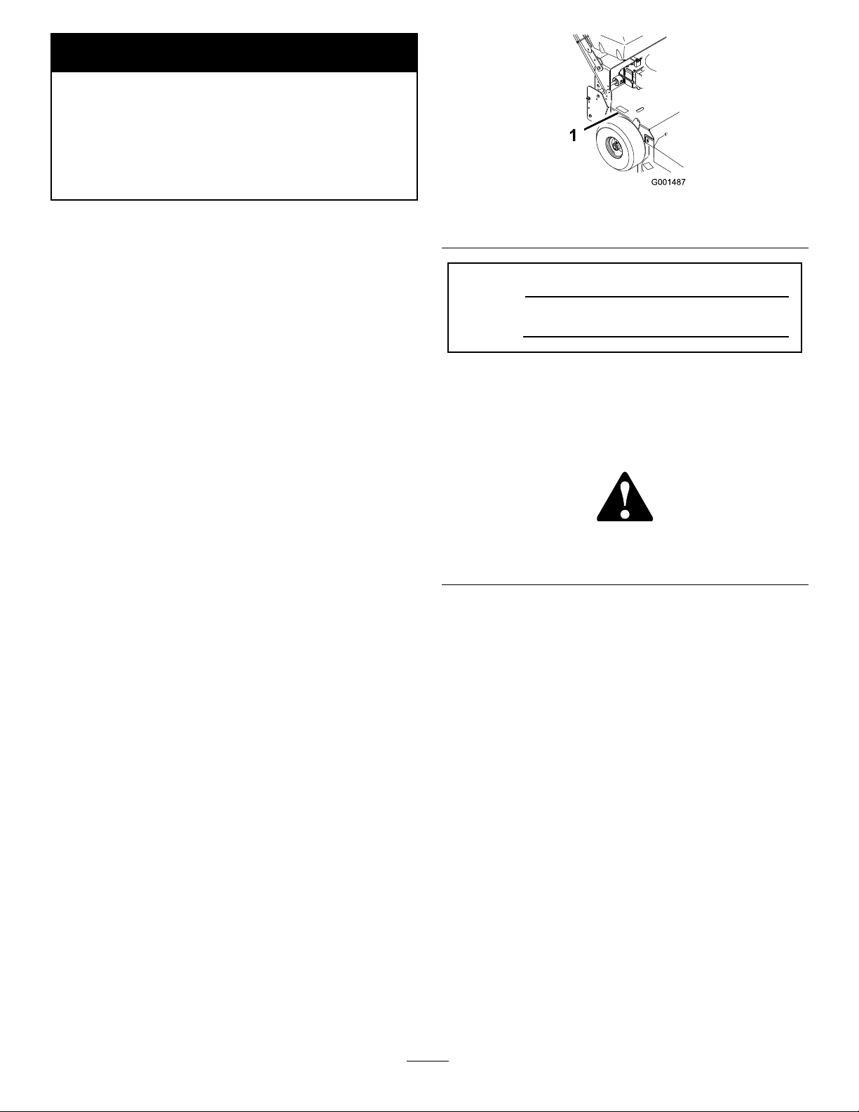
SlopeIndicator
G011841
Figure3
Thispagemaybecopiedforpersonaluse.
1.Themaximumslopeyoucansafelyoperatethemachineonis20degrees.Usetheslopecharttodeterminethedegreeofslope
ofhillsbeforeoperating.Donotoperatethismachineonaslopegreaterthan20degrees.Foldalongtheappropriateline
tomatchtherecommendedslope.
2.Alignthisedgewithaverticalsurface,atree,building,fencepole,etc.
3.Exampleofhowtocompareslopewithfoldededge.
6
Page 7
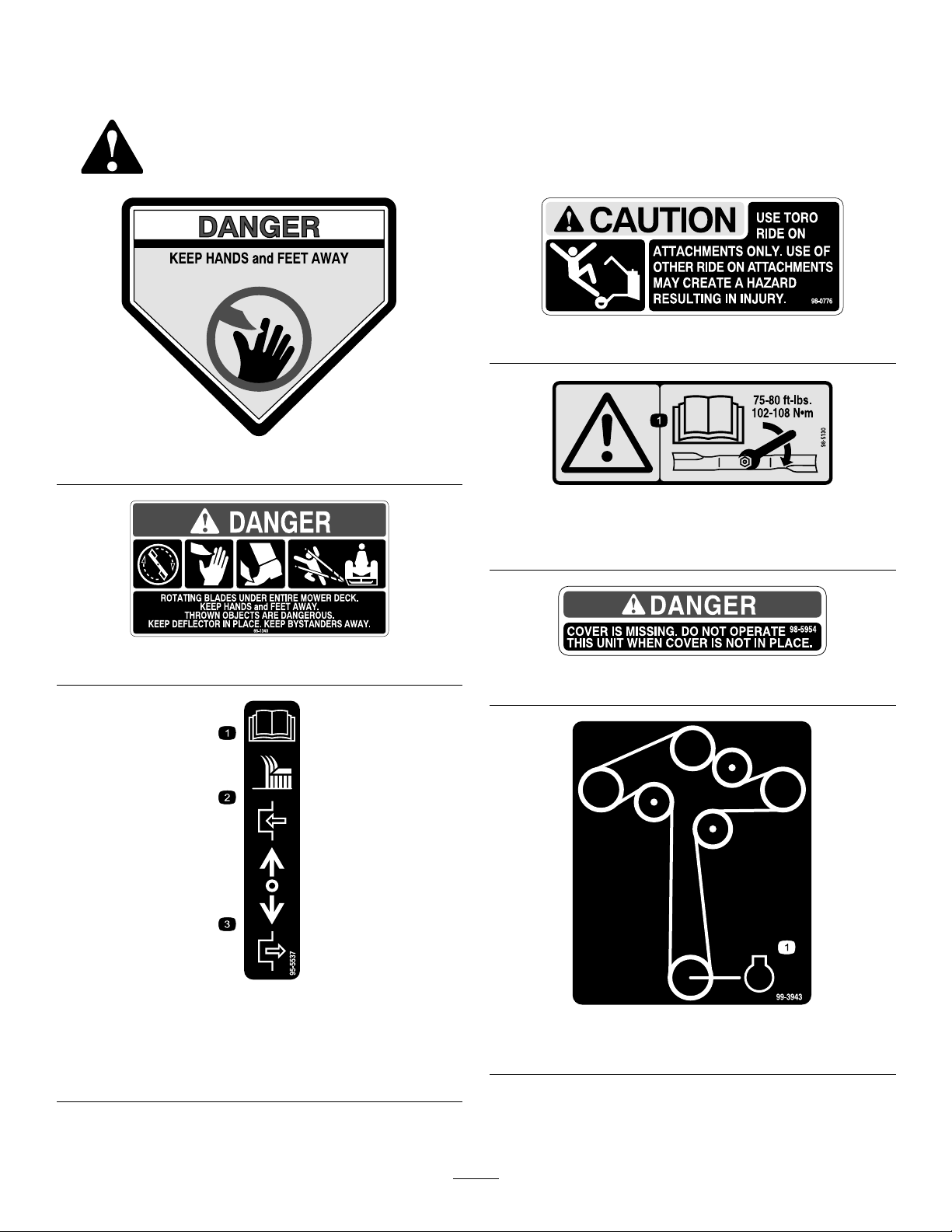
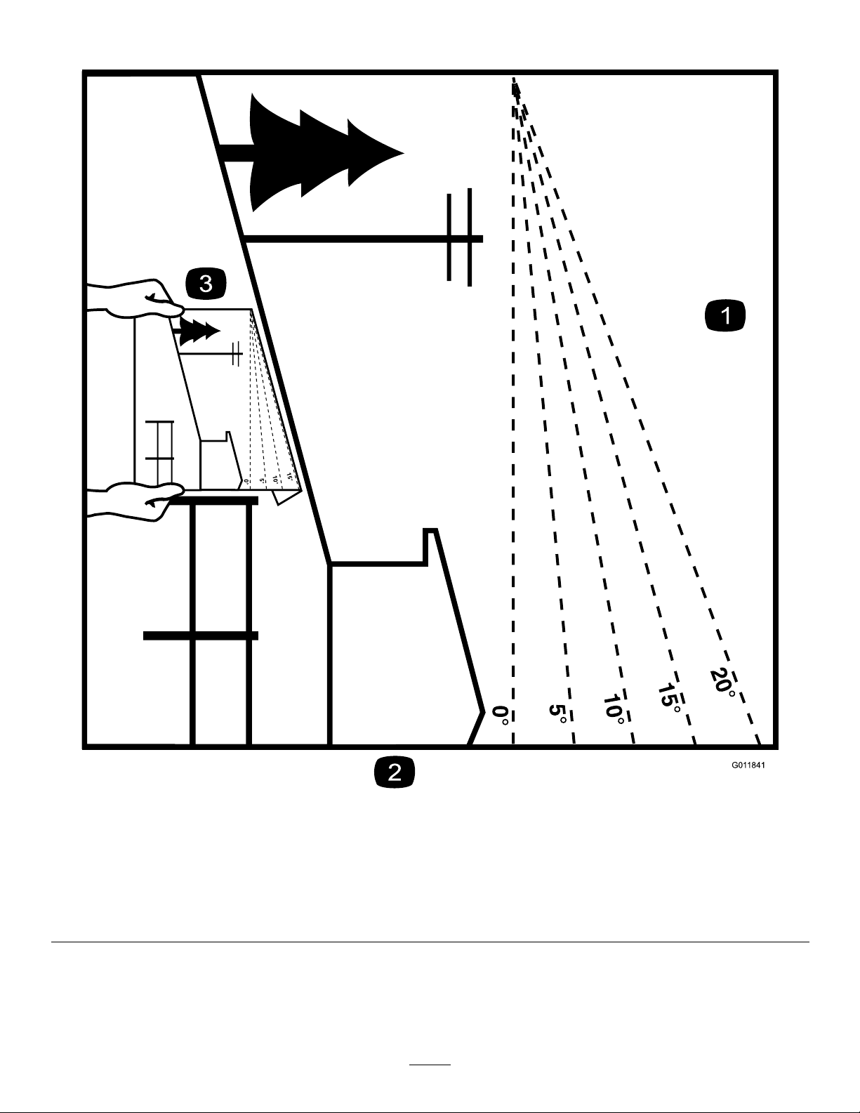
SafetyandInstructional
Decals
Safetydecalsandinstructionsareeasilyvisibletotheoperatorandarelocatednearanyareaof
potentialdanger.Replaceanydecalthatisdamagedorlost.
98-0776
43-8480
98-5130
1.Warning—readtheOperator'sManualforinstructionson
torquingthebladebolt/nutto75-80ft-lb(102-106N⋅m).
66-1340
98-5954
1.ReadtheOperator's
Manualforinstructionson
operatingthecuttingblade
2.Pushforwardtoengage
95-5537
3.Pullbacktodisengage
1.Engine
7
99-3943
Page 8
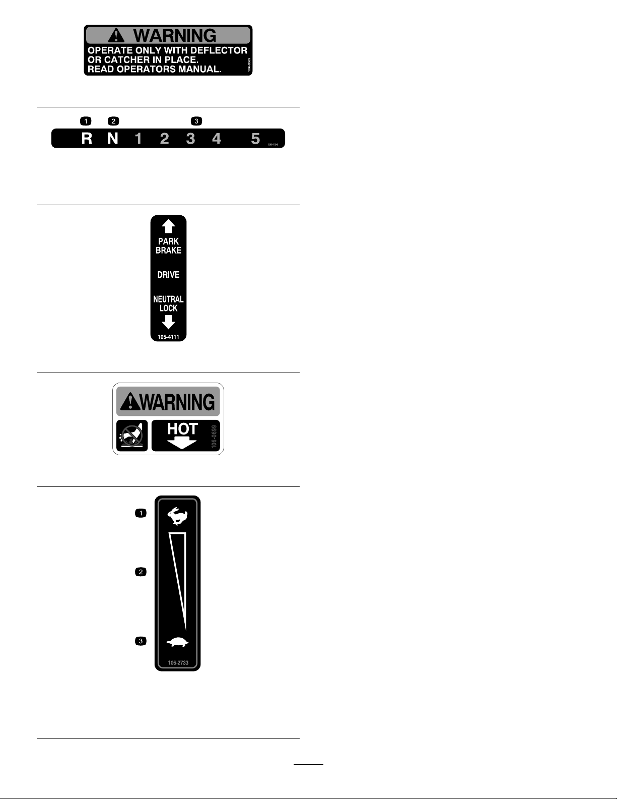
104-8569
105-4104
1.Reverse3.Transmissionspeeds
2.Neutral
105-4111
1.Fast
2.Continuousvariable
setting
106-0699
106-2733
3.Slow
8
Page 9
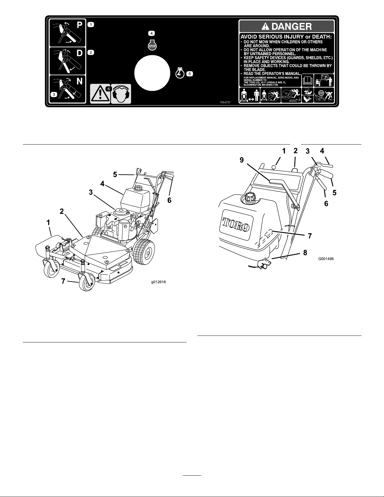
106-2737
g012616
1
2
3
4
5
6
7
1.Park3.Neutral5.Engine—run
2.Drive4.Engine—stop6.Warning—wearearprotection.
ProductOverview
Figure5
1.Throttlecontrol6.Drivelever
Figure4
1.Sidedischarge5.Controls
2.Mowerdeck6.Handle
3.Recoilstarter
4.Gastank
7.Casterwheel
2.Ignitionswitch
3.Neutral/parkingbrakelock8.Choke
4.OperatorPresence
Control(OPC)lever
5.Handle
7.Gearshiftlever
9.Powertakeofflever(PTO)
Controls
Becomefamiliarwithallthecontrols(Figure5)before
youstarttheengineandoperatethemachine.
ThrottleControl
Thethrottlecontrolhastwopositions:FastandSlow.
OperatorPresenceControl(OPC)
Levers
WhenyousqueezetheOPCleversagainstthehandles,
theOPCsystemsensesthattheoperatorisinthenormal
operatingposition.WhenyoureleasetheOPClevers,
theOPCsystemsensesthattheoperatorhasleftthe
normaloperatingposition,andthesystemwillstopthe
engineifeitherthegearshiftleverisnotintheneutral
positionorthebladecontrol(PTO)leverisengaged.
9
Page 10

GearShiftLever
36inchmowers:
Thetransmissionhasveforwardspeeds,neutraland
reverse,andhasanin-lineshiftpattern.
Important:Donotshiftwhileunitismoving,as
transmissiondamagemayoccur.
DriveLevers
Releasedriveleverstoengageforwardtractionoperation.
Squeezerightsideofdrivelevertoturnrightandleft
sidetoturnleft.
Neutral/ParkingBrakeLock
Squeezedriveleversandmovethelocksrearwardfor
neutrallock.Squeezedriveleversandmovethelocks
forwardtosettheparkingbrake.
BladeControlLever(PTO)
ThisleverisusedinconjunctionwiththeOPClevers
toengageordisengagethemowerdeckbeltanddrive
themowerblades.
Widthwithdeectordown46.6inches(1 18.4cm)
Length
Height
Weight
80inches(203.2cm)
41inches(104.1cm)
462lb(210kg)
48inchmowers:
Widthwithdeectordown63–1/2inches(161.3cm)
Length
Height
Weight
78–3/8inches(198.9cm)
41inches(104.1cm)
500lb(227kg)
Attachments/Accessories
AselectionofToroapprovedattachmentsand
accessoriesareavailableforusewiththemachineto
enhanceandexpanditscapabilities.Contactyour
AuthorizedServiceDealerorDistributororgoto
www.Toro.comforalistofallapprovedattachments
andaccessories.
RecoilStarter
Pulltherecoilstarterhandletostartengine(notshown
in).
FuelShut-offValve
Closethefuelshut-offvalvewhentransportingor
storingmower.
IgnitionSwitch
Thisswitchisusedinconjunctionwithrecoilstarterand
hastwopositions:RunandOff.
Choke
Usethechoketostartacoldengine.
Specications
Note:Specicationsanddesignaresubjecttochange
withoutnotice.
32inchmowers:
Widthwithdeectordown45.8inches(1 16.3cm)
Length
Height
Weight
78inches(198.1cm)
41inches(104.1cm)
402lb(182kg)
10
Page 11

Operation
AddingFuel
UseUnleadedRegularGasolinesuitablefor
automotiveuse(87pumpoctaneminimum).Leaded
regulargasolinemaybeusedifunleadedregularisnot
available.
Important:Neverusemethanol,gasoline
containingmethanol,orgasoholcontainingmore
than10%ethanolbecausethefuelsystemcouldbe
damaged.Donotmixoilwithgasoline.
DANGER
Incertainconditions,gasolineisextremely
ammableandhighlyexplosive.Areorexplosion
fromgasolinecanburnyouandothersandcan
damageproperty.
•Fillthefueltankoutdoors,inanopenarea,
whentheengineiscold.Wipeupanygasoline
thatspills.
•Neverllthefueltankinsideanenclosedtrailer.
•Donotllthefueltankcompletelyfull.Add
gasolinetothefueltankuntilthelevelis1/4to
1/2inch(6to13mm)belowthebottomofthe
llerneck.Thisemptyspaceinthetankallows
gasolinetoexpand.
•Neversmokewhenhandlinggasoline,andstay
awayfromanopenameorwheregasoline
fumesmaybeignitedbyaspark.
•Storegasolineinanapprovedcontainerand
keepitoutofthereachofchildren.Neverbuy
morethana30-daysupplyofgasoline.
•Donotoperatewithoutentireexhaustsystem
inplaceandinproperworkingcondition.
DANGER
Incertainconditionsduringfueling,static
electricitycanbereleasedcausingasparkwhich
canignitethegasolinevapors.Areorexplosion
fromgasolinecanburnyouandothersandcan
damageproperty.
•Alwaysplacegasolinecontainersontheground
awayfromyourvehiclebeforelling.
•Donotllgasolinecontainersinsideavehicle
oronatruckortrailerbedbecauseinterior
carpetsorplastictruckbedlinersmayinsulate
thecontainerandslowthelossofanystatic
charge.
•Whenpractical,removegas-powered
equipmentfromthetruckortrailerandrefuel
theequipmentwithitswheelsontheground.
•Ifthisisnotpossible,thenrefuelsuch
equipmentonatruckortrailerfromaportable
container,ratherthanfromagasolinedispenser
nozzle.
•Ifagasolinedispensernozzlemustbeused,
keepthenozzleincontactwiththerimofthe
fueltankorcontaineropeningatalltimesuntil
fuelingiscomplete.
WARNING
Gasolineisharmfulorfatalifswallowed.
Long-termexposuretovaporscancauseserious
injuryandillness.
•Avoidprolongedbreathingofvapors.
•Keepfaceawayfromnozzleandgastankor
conditionerbottleopening.
•Keepgasawayfromeyesandskin.
UsingStabilizer/Conditioner
Useafuelstabilizer/conditionerinthemachineto
providethefollowingbenets:
•Keepsgasolinefreshduringstorageof90daysor
less.Forlongerstorageitisrecommendedthatthe
fueltankbedrained.
•Cleanstheenginewhileitruns
•Eliminatesgum-likevarnishbuildupinthefuel
system,whichcauseshardstarting
Important:Donotusefueladditives
containingmethanolorethanol.
Addthecorrectamountofgasstabilizer/conditioner
tothegas.
11
Page 12
Note:Afuelstabilizer/conditionerismost
effectivewhenmixedwithfreshgasoline.To
minimizethechanceofvarnishdepositsinthefuel
system,usefuelstabilizeratalltimes.
FillingtheFuelTank
1.Shuttheengineoffandsettheparkingbrake.
2.Cleanaroundfueltankcapandremovethecap.
Addunleadedregulargasolinetofueltank,untilthe
levelis1/4to1/2inch(6to13mm)belowthe
bottomofthellerneck.Thisspaceinthetank
allowsgasolinetoexpand.Donotllthefueltank
completelyfull.
3.Installfueltankcapsecurely.Wipeupanygasoline
thatmayhavespilled.
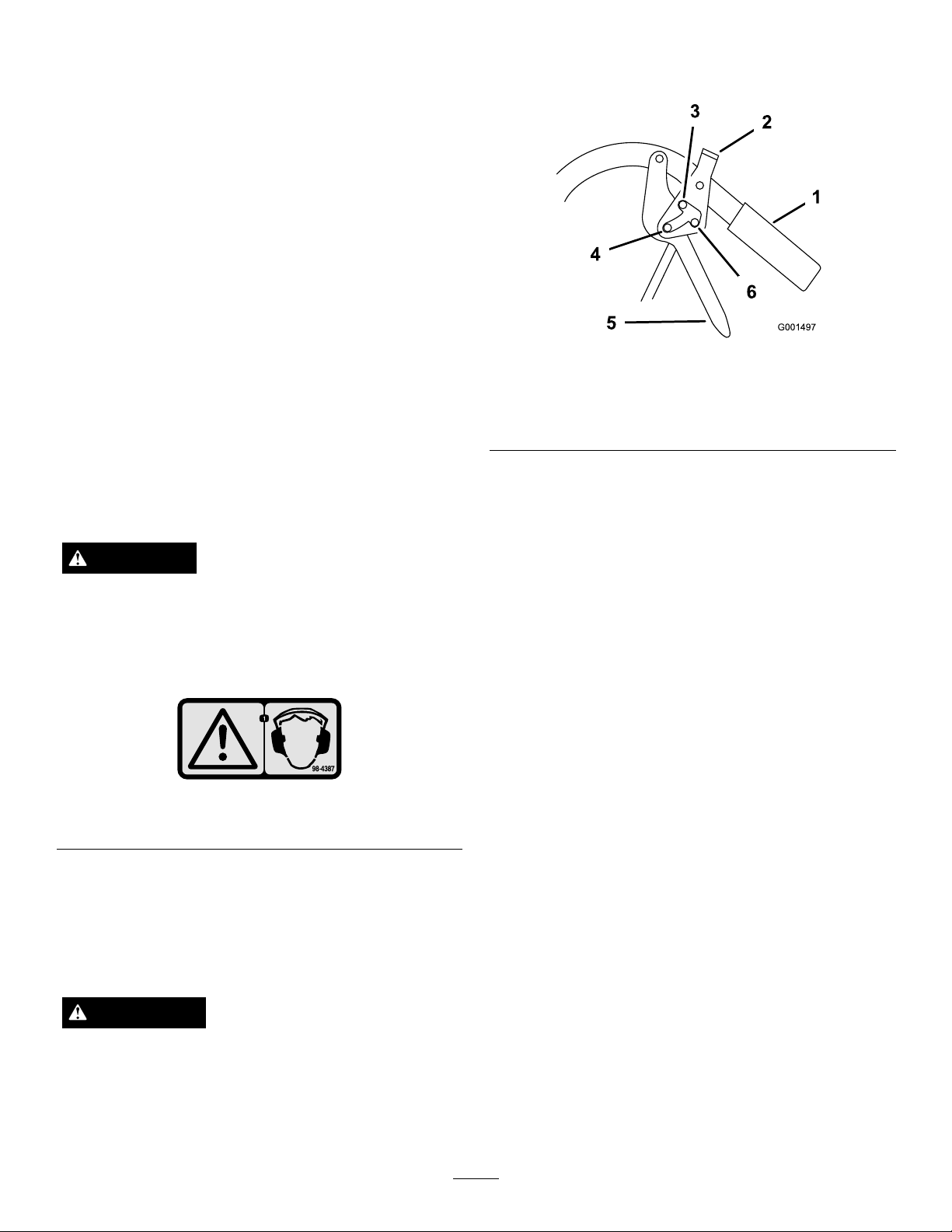
SettingtheParkingBrakes
1.Squeezethedrivelevers(Figure7).
Figure7
ThinkSafetyFirst
Carefullyreadallthesafetyinstructionsanddecalsin
thesafetysection.Knowingthisinformationcould
helpyouoranybystandersavoidinjury.
Theuseofprotectiveequipmentforeyes,hearing,feet
andheadisrecommended.
CAUTION
Thismachineproducessoundlevelsinexcessof
85dBAattheoperator'searandcancausehearing
lossthroughextendedperiodsofexposure.
Wearhearingprotectionwhenoperatingthis
machine.
Figure6
1.Warning—wearhearingprotection.
1.Handle
2.Neutral/parkingbrakelock
3.Parkposition6.Neutralposition
2.Placeyourthumbsontheupperpartofthelocks
andmovethemforwardinintotheparkposition
(Figure7).
3.Releasethedrivelevers.
4.Fullspeedforward
5.Drivelever
ReleasingtheParkingBrakes
1.Squeezethedriveleversback(Figure7).
2.Placeyourthumbsontheupperpartofthelocks
andmovethemrearwarduntiltheyareinthedrive
position(Figure7).
SettingtheNeutralLocks
1.Squeezethedriveleversback(Figure7).
2.Placeyourthumbsontheupperpartofthelocks
andmovethemrearwardintotheneutrallock
position(
Figure7).
OperatingtheParkingBrake
andNeutralLocks
Alwayssettheparkingbrakeswhenyoustopthe
machineorleaveitunattended.
WARNING
Childrenorbystandersmaybeinjuredifthey
moveorattempttooperatethemachinewhileit
isunattended.
Alwayssettheparkingbrakewhenleavingthe
machineunattended,evenifjustforafewminutes.
ReleasingtheNeutralLocks
1.Squeezethedriveleversback.
2.Placeyourthumbsontheupperpartofthelocks
andmovethemforwarduntiltheyareinthedrive
position(
Figure7).
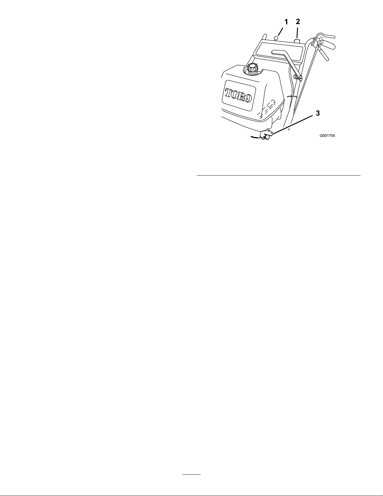
StartingandStoppingthe
Engine
StartingtheEngine
1.Connectthewirestothesparkplugs.
2.Openthefuelvalve.
12
Page 13
3.Disengagethebladecontrol(PTO)leverandmove
theshiftlevertotheneutralposition.
4.Settheparkingbrakes.
5.Turntheignitionkeytotherunposition(
6.Tostartacoldengine,movethethrottlecontrol
midwaybetweenthefastandslowpositions.
7.Tostartawarmengine,movethethrottlecontrol
tothefastposition.
8.Pullthechokeknobiftheengineiscold(
Note:Awarmorhotengineusuallydoesnot
requireanychoking.
9.Grasptherecoilstarterhandlermlyandpullit
outuntilpositiveengagementresults;thenpullthe
handlevigorouslytostarttheengine.Allowthe
ropetorecoilslowly .
Important:Donotpulltherecoilropetoits
limitorreleasethestarterhandlewhenyoupull
outtheropebecausetheropemaybreakorthe
recoilassemblymaybedamaged.
10.Pushthechoketooffastheenginewarmsup.
11.Iftheengineiscold,allowittowarmupandthen
movethethrottlecontroltothefastposition.
Figure8).
Figure8).
Figure8
1.Throttlecontrol
2.Ignitionswitch
3.Choke
OperatingtheBladeControl
(PTO)Lever
Thebladecontrol(PTO)leverengagesanddisengages
thepowertothemowerblades.
StoppingtheEngine
Important:Inanemergency,youcanstopthe
engineimmediatelybyturningtheignitionkeyto
the
of f
position.
1.Movethethrottlelevertotheslowposition
Figure8).
(
Note:Iftheenginehasbeenworkinghardoris
hot,letitidleforaminutebeforestoppingitto
helpcoolit.
2.Turntheignitionkeytotheoffposition.
3.Settheparkingbrakesandremovethekey.
4.Disconnectthewirefromthesparkplugtoprevent
someonefromaccidentallystartingthemachine
whiletransportingorstoringit.
5.Closethefuelshut-offvalvebeforetransporting
orstoringthemachine.
Important:Closethefuelshut-offvalvebefore
transportingorthestoringthemachineto
preventfuelleakage.
EngagingtheMowerBlades(PTO)
1.Squeezetheoperatorpresencecontrol(OPC)levers
againstthehandles(Figure9).
2.Pushthebladecontrol(PTO)leverrmlyforward
untilitlatchesoverthecenter(
3.Restarttheengineandrepeattheprocedureto
engagethemowerbladesiftheoperatorpresence
control(OPC)leversarereleased.
Figure9).
DisengagingtheMowerBlades(PTO)
Todisengagetheblades,pullthebladecontrollever
rearwardalltheway(Figure9).Theenginewillkill
whentheOPCleversarereleasedwiththebladecontrol
leverengaged.
13
Page 14
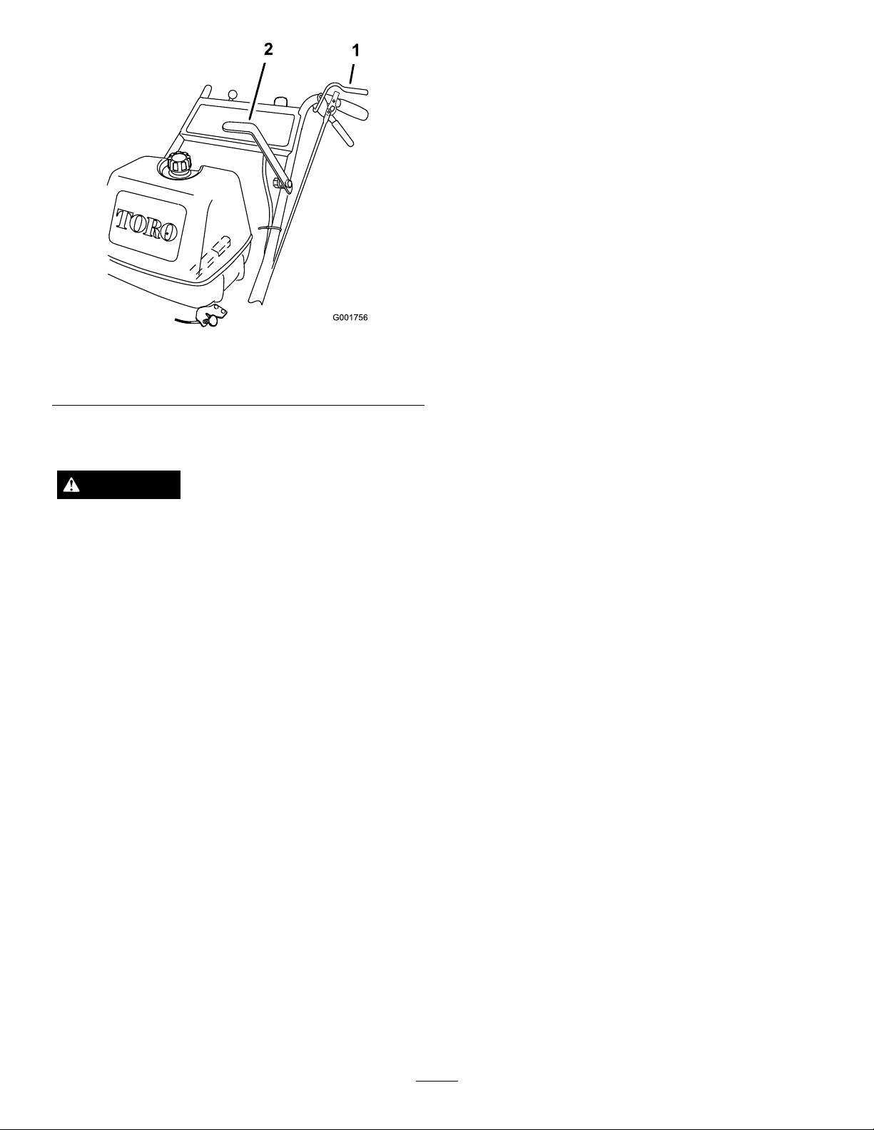
Figure9
1.OperatorPresence
Control(OPC)lever
2.Powertakeofflever(PTO)
TheSafetyInterlockSystem
CAUTION
Ifsafetyinterlockswitchesaredisconnectedor
damagedthemachinecouldoperateunexpectedly
causingpersonalinjury.
•Donottamperwiththeinterlockswitches.
TestingtheSafetyInterlockSystem
Testthesafetyinterlocksystembeforeyouusethe
machineeachtime.Ifthesafetysystemdoesnot
operateasdescribed,haveanAuthorizedServiceDealer
repairthesafetysystemimmediately .
1.Settheparkingbrakes,movetheshiftleverintothe
Neutralposition,disengagethebladecontrol(PTO)
leverandplacethethrottleforward.
2.Starttheengine;refertoStartingtheEngine.
3.WithoutholdingtheOperatorPresenceControl
(OPC)levers,engagethebladecontrol(PTO)lever.
Theengineshouldstop.
4.Disengagethebladecontrol(PTO)lever.
5.Withtheenginerunning,holddowntheOPClevers
andengagethebladecontrol(PTO)lever.The
mowerbeltshouldengageandthemowerblades
beginrotating.
6.ReleasetheOPClevers.Theengineshouldstop.
7.Withtheenginerunning,movetheshiftleverinto
gearandreleasetheOPClevers.Theengineshould
stop.
8.Withtheenginerunning,turntheignitionkeyto
theoffposition.Theengineshouldstop.
9.Ifalltheaboveconditionsarenotmet,havean
AuthorizedServiceDealerrepairthesafetysystem
immediately.
•Checktheoperationoftheinterlockswitches
dailyandreplaceanydamagedswitchesbefore
operatingthemachine.
UnderstandingtheSafetyInterlock
System
Thesafetyinterlocksystemisdesignedtopreventthe
enginefromstartingunless:
•Thebladecontrol(PTO)leverisdisengaged.
•ThemachineisshiftedintotheNeutralposition.
•TheignitionkeyisintheRunposition.
Thesafetyinterlocksystemisdesignedtostopthe
enginewhen:
•TheOperatorPresenceControl(OPC)leversare
releasedwhenthetransmissionorthebladesare
engaged;
•TheignitionkeyisturnedtotheOffposition.
•Themachineisshiftedintogearwithoutholding
theOPClevers.
•Thebladecontrol(PTO)leverisengagedwithout
holdingtheOPClevers.
DrivingForwardorBackward
Thethrottlecontrolregulatestheenginespeedas
measuredinRPM(revolutionsperminute).Move
thethrottlecontrolintotheFastpositionforthebest
mowingperformance.
DrivingForward
1.Ensurethattheparkingbrakesareengaged.
2.SqueezetheOPCleversagainstthehandles.
3.Movetheshiftleverintoaforwardgear.
4.Releasetheparkingbrakes;refertoReleasingthe
ParkingBrakesandNeutralLocks.
5.Slowlyreleasethedrivelevers.
Note:Togostraight,releasethedrivelevers
equally.Toturn,squeezethedriveleveronthesame
sideasthedirectionyouwanttoturn.
DrivingBackward
1.Ensurethattheparkingbrakesareengaged.
2.SqueezetheOPCleversagainstthehandles.
3.Movetheshiftleverintothereversegear.
14
Page 15

4.Releasetheparkingbrakes;refertoReleasingthe
ParkingBrakesandNeutralLocks.
5.Slowlyreleasethedrivelevers.
Note:Youmustpullthemowerbackwardtoassist
itsrearwardmovement.
StoppingtheMower
1.Squeezethedriveleversallthewaybacktoengage
thebrakes.
2.Settheparkingbrakes.RefertoSettingtheParking
Brakes.
3.ShifttransmissionintotheNeutralposition.
4.MovethethrottletotheStopposition,andwaitfor
allmovingpartstostopbeforeleavingtheoperating
position.
CAUTION
Childrenorbystandersmaybeinjuredifthey
moveorattempttooperatethemachinewhile
itisunattended.
Alwaysremovetheignitionkeyandsetthe
parkingbrakewhenleavingthemachine
unattended,evenifjustforafewminutes.
TransportingMachines
Useaheavy-dutytrailerortrucktotransportthe
machine.Ensurethatthetrailerortruckhasall
necessarylightingandmarkingasrequiredbylaw .
Pleasecarefullyreadallthesafetyinstructions.Knowing
thisinformationcouldhelpyou,yourfamily ,petsor
bystandersavoidinjury.
DANGER
Withoutthegrassdeector,dischargecover,or
completegrasscatcherassemblymountedin
place,youandothersareexposedtobladecontact
andthrowndebris.Contactwithrotatingmower
blade(s)andthrowndebriswillcauseinjuryor
death.
•Neverremovethegrassdeectorfromthe
mowerbecausethegrassdeectorroutes
materialdowntowardtheturf.Ifthe
grassdeectoriseverdamaged,replaceit
immediately.
•Neverputyourhandsorfeetunderthemower.
•Nevertrytocleardischargeareaormower
bladesunlessyoureleasethebailandthepower
takeoff(PTO)isoff.Rotatetheignitionkeyto
Off.Alsoremovethekeyandpullthewireoff
thesparkplug(s).
AdjustingtheWheelDrive
Tension
Youmayneedtoincreasethewheeldrivebelttension
undercertainoperatingconditions,suchasmowerover
hillyterrainorwhilepullingasulky.
1.Stoptheengine,removethekey ,andwaitforall
movingpartstostop.
2.Disconnectthewiresfromthesparkplugs.
3.Disengagetheneutral/parkingbrakelocks,and
releasethedriveleverstoreducethespringforce.
4.Removethedrivespringfromtheadjustmentbolt
Figure10).
(
Totransportthemachine:
1.Stoptheengine,removethekey ,setthebrake,and
closethefuelvalve.
2.Securelyfastenthemachinetothetrailerortruck
withstraps,chains,cable,orropes.
3.Secureatrailertotowingvehiclewithsafetychains.
4.Ifapplicable,connectthetrailerbrakes.
SideDischargingorMulching
theGrass
Thismowerhasahingedgrassdeectorthatdisperses
clippingstothesideanddowntowardtheturf.
1.PositionA4.Drivespring
2.PositionB
3.PositionC
15
Figure10
5.Adjustmentbolt(In
positionA)
6.Drivepulleyshield
Page 16

5.Removethelocknutthatsecurestheadjustment
bolttothedrivepulleyshield(Figure10).
6.Locateboltassemblyinthedesiredtensionposition
asfollows:
•PositionAfornormalconditions
•PositionBformoresevereconditions
•PositionCforthemostsevereconditions
Note:Thewheeldrivetensionislowestwhen
theboltassemblyisinPositionA.Thetension
increasesinPositionsBandC(
Figure10).
7.Installtheadjustmentboltandthedrivespring.
8.Repeatstepsthroughfortheoppositeside.
AdjustingtheHeight-of-Cut
Thismachinehasa1to4-1/4inch(26to108mm)
rangefortheheight-of-cut.Thiscanbeachievedby
adjustingbladespacers,rearaxleheight,andfront
casterspacers.UsetheHeight-of-CutCharttoselect
thecombinationofadjustmentsrequired.
AdjustingtheBladeHeight
Adjustthebladesbyusingthe4spacers(1/4inch)
(6mm)onthebladespindlebolts.Thisallowsfora
1-inch(25mm)adjustmentrange,in1/4inch(6mm)
increments,ofcuttingheightinanyaxleposition.Use
thesamenumberofbladespacersonallbladesto
achievealevelcut(2aboveand2below,1aboveand3
below,etc.).
1.Disengagethebladecontrol(PTO)leverandset
theparkingbrakes.
2.Stoptheengineandwaitforallmovingpartsto
stopbeforeleavingtheoperatingposition.
3.Holdthebladeboltandremovethenut(
Figure11).
Figure11
1.Blade
2.Bladebolt5.Thinwasher
3.Curvedwasher
4.Spacer
6.Nut
4.Slidetheboltdownthroughthespindle,andchange
thespacersasneeded(
Figure11).
5.Installtheboltandcurvedwasher,addextra
spacer(s),andsecurethemwithathinwasheranda
nut(Figure11).
6.Torquethebladeboltto75-80ft-lb(101-108N-m).
AdjustingtheAxleHeight
Adjusttheaxlepositiontotheselectedheight-of-cut
setting.RefertotheHeight-of-CutChart.
1.Disengagethebladecontrol(PTO)leverandset
theparkingbrakes.
2.Stoptheengineandwaitforallmovingpartsto
stopbeforeleavingtheoperatingposition.
3.Loosen,butdonotremove,the2axlepivotbolts
andthe2axleadjustmentbolts(
16
Figure12).
Page 17

Figure12
g012931
1.Axlepivotbolt2.Axleadjustmentbolt
4.Placeajackundertherearcenteroftheengine
frame.Raisethebackendoftheengineframeup
enoughtoremovethefront2axleadjustmentbolts
Figure12).
(
Note:Usejackstandstosupportthemachine.
5.Raiseorlowertheengineframewiththejacksothat
youcaninstallthefront2axleadjustmentboltsin
thedesiredholelocation(Figure12).
2.Removethelatchpin,slidethecasterfromthe
support,andchangethespacers(Figure13).
3.Installthecasterinthesupportandinsertthelatch
Figure13).
pin(
AdjustingtheHandleHeight
Thehandlepositioncanbeadjustedtomatchthe
operator'sheightpreference.
1.Removethehairpincotterpinsandclevispinsfrom
thedriveleversandneutrallocks(
Figure14).
Note:Useataperedpunchtohelpaligntheholes.
6.Tightenall4boltsandlowerthemower.
7.Adjustthecontrolrodsandthebrakelinkages
asrequired.RefertoServicingtheBrakesand
AdjustingtheControlRods.
Important:Y oumustadjustthecontrolrods
andthebrakelinkagewhenyouchangetheaxle
positionsforpropertractionandbrakefunction.
AdjustingtheCasterPosition
1.UsingtheHeight-of-CutChart,adjustthecaster
spacerstomatchwiththeaxleholeselected
Figure13).
(
Figure14
1.Controlrod
2.Clevispin
3.OperatorPresence
Controllever(OPC)
4.Handle
5.Neutrallock
6.Hairpincotterpin
7.Drivelever
2.Loosentheupperbolts(3/8x1-1/4inches)and
angenutsecuringhandletorearframe(
Figure15).
3.Removethelowerbolts(3/8x1inch)andange
nutssecuringhandletorearframe(Figure15).
4.Pivotthehandletothedesiredoperatingposition
andinstallthelowerangebolts(3/8x1inch)and
angenutsintothemountingholes.Tightenall
angebolts.
1.Latchpin
2.Spacer,3/16inch(5mm)
Figure13
3.Spacer,1/2inch(13mm)
17
Page 18

Figure15
1.Upperhandle6.Lowermountingholes
2.Rearframe
3.Flangebolt(3/8x1inch)
4.Locknut(3/8inch)
5.Uppermountinghole
7.Lowposition
8.Middleposition
9.Highposition
5.Adjustthecontrolrodlengthbyrotatingthecontrol
rodintherodtting(
Figure14).
6.Installahairpincotterbetweenthedriveleversand
neutrallocksandintotheclevispins(Figure14).
Note:Makesuretheclevispinsareinsertedinto
theneutrallocks.
7.Checktheparkingbrakeadjustment.Referto
CheckingtheBrakesin
BrakeMaintenance(page28).
18
Page 19

HeightofCutChart
Numberofspacers
1/2inch
AxlePosition
A00
A01
A10
B01
B10
B11
B20
C
C
C
C
D21
D30
D31
D40
E31
E40
E41
(13mm)
11
20
21
30
belowcaster
3/16inch(5
mm)
1inch(26
1–1/8inch
(29mm)
1–3/8inch
(35mm)
1–3/8inch
(35mm)
1–5/8inch
(41mm)
1–3/4inch
(45mm)
2inch(51
1–7/8inch
(48mm)
2–1/8inch
(55mm)
2–1/4inch
(57mm)
2–1/2inch
(64mm)
2–3/8inch
(61mm)
2–1/2inch
(64mm)
2–3/4inch
(70mm)
3inch(76
2–7/8inch
(73mm)
3–1/8inch
(79mm)
3–1/4inch
(82mm)
Numberof1/4inchbladespacersbelowspindle
43210
mm)
mm)
mm)
1–1/4inch
(32mm)
1–3/8inch
(35mm)
1–5/8inch
(41mm)
1–5/8inch
(41mm)
1–7/8inch
(48mm)
2inch(51
mm)
2–1/4inch
(57mm)
2–1/8inch
(54mm)
2–3/8inch
(60mm)
2–1/2inch
(64mm)
2–3/4inch
(70mm)
2–5/8inch
(67mm)
2–3/4inch
(70mm)
3inch(76
mm)
3–1/4inch
(82mm)
3–1/8inch
(79mm)
3–3/8inch
(86mm)
3–1/2inch
(89mm)
1–1/2inch
(38mm)
1–5/8inch
(41mm)
1–7/8inch
(48mm)
1–7/8inch
(48mm)
2–1/8inch
(54mm)
2–1/4inch
(57mm)
2–1/2inch
(64mm)
2–3/8inch
(60mm)
2–5/8inch
(67mm)
2–3/4inch
(70mm)
3inch(76
2–7/8inch
(73mm)
3inch(76
3–1/4inch
(82mm)
3–1/2inch
(89mm)
3–3/8inch
(86mm)
3–5/8inch
(92mm)
3–3/4inch
(95mm)
1–3/4inch
(45mm)
1–7/8inch
(48mm)
2–1/8inch
(54mm)
2–1/8inch
(54mm)
2–3/8inch
(60mm)
2–1/2inch
(64mm)
2–3/4inch
(70mm)
2–5/8inch
(67mm)
2–7/8inch
(73mm)
3inch(76
mm)
mm)
mm)
3–1/4inch
(83mm)
3–1/8inch
(79mm)
3–1/4inch
(82mm)
3–1/2inch
(89mm)
3–3/4inch
(95mm)
3–5/8inch
(92mm)
3–7/8inch
(98mm)
4inch(102
mm)
2inch(51
mm)
2–1/8inch
(54mm)
2–3/8inch
(60mm)
2–3/8inch
(60mm)
2–5/8inch
(67mm)
2–3/4inch
(70mm)
3inch(76
mm)
2–7/8inch
(73mm)
3–1/8inch
(79mm)
3–1/4inch
(83mm)
3–1/2inch
(89mm)
3–3/8inch
(86mm)
3–1/2inch
(89mm)
3–3/4inch
(95mm)
4inch(102
mm)
3–7/8inch
(98mm)
4–1/8inch
(105mm)
4–1/4inch
(108mm)
19
Page 20

Maintenance
Note:Determinetheleftandrightsidesofthemachinefromthenormaloperatingposition.
RecommendedMaintenanceSchedule(s)
MaintenanceService
Interval
Aftertherst8hours
Aftertherst25hours
Beforeeachuseordaily
Every25hours
Every50hours
Every100hours
MaintenanceProcedure
•Changetheengineoil.
•Checkthemowerbelttension.
•Checkthemowerbelttension.
•Checkthesafetysystem.
•Greasethecasterwheelsandcasterpivot.
•Checktheengineoillevel.
•Cleantheairintakescreen.
•Cleantheairintakescreen.
•Checkthebrakes.
•Inspecttheblades.
•Cleanthemowerdeck.
•Cleanfoamaircleanerelement.
•Greasethemowerbeltidler.
•Checkthepaperaircleanerelement.
•Checkthetirepressure.
•Checkthebelts.
•Checkthemowerbelttension.
•Changetheengineoil.
•Checkthesparkplugs.
•Checkandcleanenginecoolingnsandshrouds.
•Replacethepaperaircleanerelement.
Every200hours
Every250hours
Every400hours
Beforestorage
•Changetheoillter.
•Replacethefuellter.
•Greasethetransmissioncouplers(moreoftenindirtyordustyconditions).
•Greasethewheelbearings(moreoftenindirtyordustyconditions).
•Paintchippedsurfaces.
•Performallmaintenanceprocedureslistedabovebeforestorage.
Important:Refertoyourengineoperator'smanualforadditionalmaintenanceprocedures.
CAUTION
Ifyouleavethekeyintheignitionswitch,someonecouldaccidentlystarttheengineandseriouslyinjure
youorotherbystanders.
Removethekeyfromtheignitionanddisconnectthesparkplugwirefromthesparkplug(s)beforeyoudo
anymaintenance.Setthewireasidesothatitdoesnotaccidentallycontactthesparkplug.
20
Page 21
Lubrication
GreasewithNo.2generalpurposelithiumbaseor
molybdenumbasegrease.
HowtoGrease
1.DisengagethePTOandsettheparkingbrake.
2.Stoptheengine,removethekey,andwaitforall
movingpartstostopbeforeleavingtheoperating
position.
3.Cleanthegreasettingswitharag.Makesureto
scrapeanypaintoffthefrontofthetting(s).
4.Connectagreaseguntothetting.Pumpgrease
intothettingsuntilgreasebeginstooozeoutof
thebearings.
5.Wipeupanyexcessgrease.
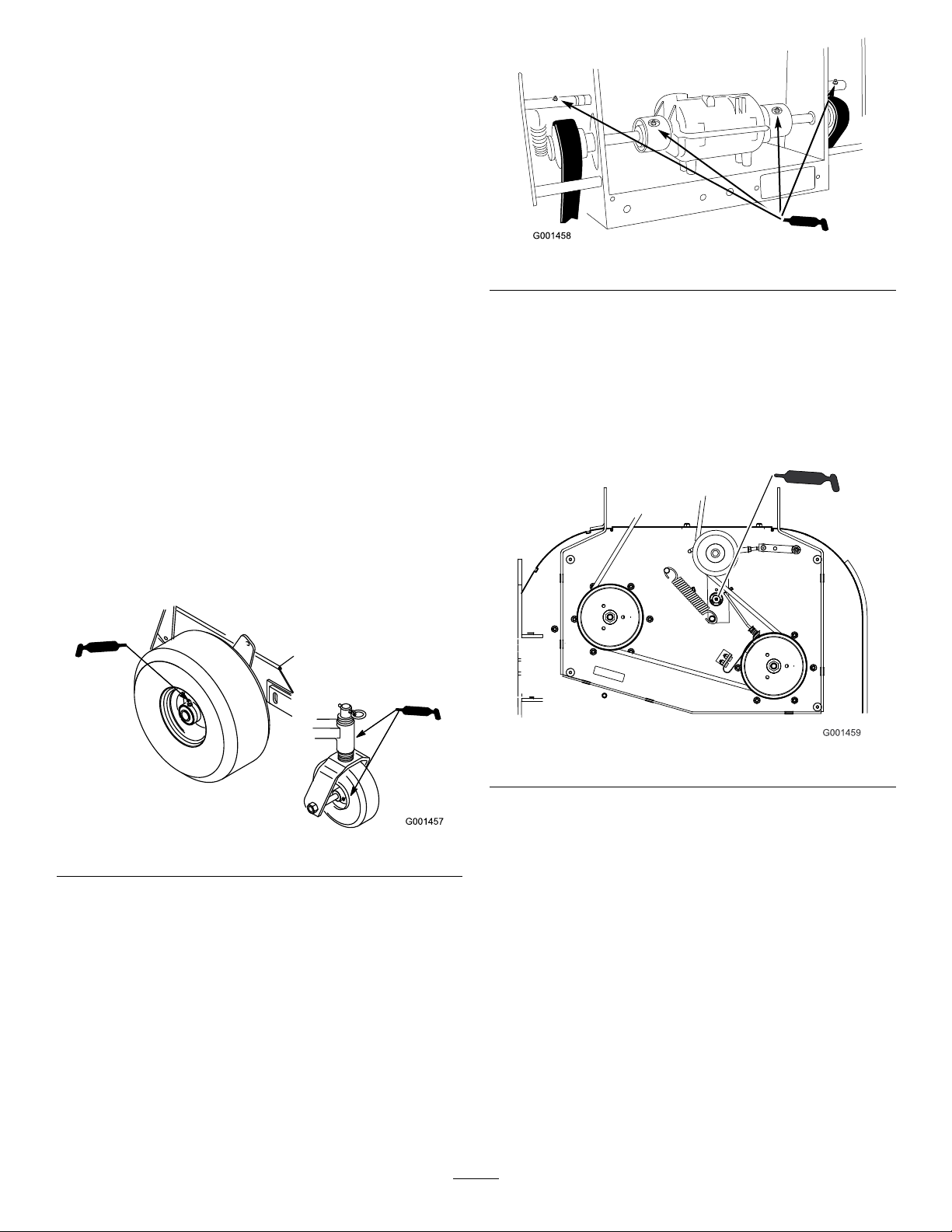
LubricatingtheCasterand
WheelBearings
Figure17
GreasingtheMowerBeltIdler
Greasethettingonthemowerbeltidlerarmpivot
(Figure18).
Note:Removethemowerdeckcovertoaccessthe
greasettingforthemowerbeltidlerarm.
1.Lubricatethefrontwheelbearingsandfrontspindles
(Figure16).
2.Lubricatethedrivewheelbearings.
Figure16
GreasingtheTransmission
Couplers
Figure18
Lubricatethetransmissioncouplerslocatedintheback
ofthemachine(
Figure17).
21
Page 22

EngineMaintenance
ServicingtheAirCleaner
ServiceInterval/Specication
ServiceInterval:Every25hours—Cleanfoamair
cleanerelement.
Every50hours—Checkthepaperair
cleanerelement.
Every200hours—Replacethepaper
aircleanerelement.
Note:Servicetheaircleanermorefrequently(every
fewoperatinghours)iftheoperatingconditionsare
extremelydustyorsandy .
Important:Donotoilthefoamorpaperelement.
RemovingtheFoamandPaper
Elements
1.DisengagethePTOandsettheparkingbrake.
2.Stoptheengine,removethekey,andwaitforall
movingpartstostopbeforeleavingtheoperating
position.
3.Cleanaroundtheaircleanertopreventdirt
fromgettingintotheengineandcausingdamage
Figure19).
(
4.Unscrewthecoverknobsandremovetheaircleaner
cover(Figure19).
5.Unscrewthehoseclampandremovetheaircleaner
assembly(
6.Carefullypullthefoamelementoffthepaper
element(
Figure19).
Figure19).
Figure19
1.Cover
2.Hoseclamp4.Foamelement
3.Paperelement
CleaningtheFoamAirCleanerElement
1.Washthefoamelementinliquidsoapandwarm
water.Whentheelementisclean,rinseitthoroughly .
2.Drytheelementbysqueezingitinacleancloth.
Important:Replacethefoamelementifitis
tornorworn.
ServicingthePaperAirCleaner
Element
1.Donotcleanthepaperlter,replaceit(Figure19).
2.Inspecttheelementfortears,anoilylm,ordamage
totherubberseal.
3.Replacethepaperelementifitisdamaged.
InstallingtheFoamandPaperElements
Important:Topreventenginedamage,always
operatetheenginewiththecompletefoamand
paperaircleanerassemblyinstalled.
1.Carefullyslidethefoamelementontothepaperair
cleanerelement(Figure19).
2.Placetheaircleanerassemblyontotheaircleaner
baseandsecureitwiththe2wingnuts(Figure19).
3.Placetheaircleanercoverintopositionandtighten
thecoverknob(Figure19).
22
Page 23

ServicingtheEngineOil
ServiceInterval/Specication
ServiceInterval:Beforeeachuseordaily—Checkthe
engineoillevel.
Aftertherst8hours—Changethe
engineoil.
Every100hours—Changetheengine
oil.
Every200hours—Changetheoil
lter.
Figure21
1.Oildipstick
2.Fillertube
Note:Changetheoilmorefrequentlywhenthe
operatingconditionsareextremelydustyorsandy.
OilType:Detergentoil(APIserviceSF ,SG,SH,SJ
orSL)
CrankcaseCapacity:58ounces(1.7liter)withthelter
removed;51ounces(1.5liter)withoutthelterremoved
Viscosity:Refertothetable(
Figure20
Figure20).
5.Unscrewtheoildipstickandwipetheendclean
(Figure21).
6.Slidetheoildipstickfullyintothellertube,butdo
notthreadontotube(
Figure21).
7.Pullthedipstickoutandlookattheend.Iftheoil
levelislow ,slowlypouronlyenoughoilintotheller
tubetoraisetheleveltotheFullmark.
Important:Donotoverllthecrankcasewith
oilandruntheengine;enginedamagecan
result.
ChangingtheEngineOil
1.Starttheengineandletitrunveminutes.This
warmstheoilsoitdrainsbetter.
2.Parkthemachinesothatthedrainsideisslightly
lowerthantheoppositesidetoassuretheoildrains
completely.
3.DisengagethePTOandsettheparkingbrake.
4.Stoptheengine,removethekey,andwaitforall
movingpartstostopbeforeleavingtheoperating
position.
CheckingtheEngineOilLevel
1.Parkthemachineonalevelsurface.
2.DisengagethePTOandsettheparkingbrake.
3.Stoptheengine,removethekey,andwaitforall
movingpartstostopbeforeleavingtheoperating
position.
4.Cleanaroundtheoildipstick(Figure21)sothatdirt
cannotfallintothellerholeanddamagetheengine.
5.Slidethedrainhoseovertheoildrainvalve.
6.Placeapanbelowthedrainhose.Rotateoildrain
valvetoallowoiltodrain(
Figure22).
7.Whenoilhasdrainedcompletely,closethedrain
valve.
8.Removethedrainhose(Figure22).
Note:Disposeoftheusedoilatarecyclingcenter.
23
Page 24

4.Installthereplacementoilltertothelteradapter,
1
turntheoillterclockwiseuntiltherubbergasket
contactsthelteradapter,thentightenthelteran
additional3/4turn(
Figure23).
5.Fillthecrankcasewiththepropertypeofnewoil;
refertoServicingtheEngineOil.
6.Runtheengineforabout3minutes,stoptheengine,
andcheckforoilleaksaroundtheoillteranddrain
valve.
7.Checktheengineoillevelandaddoilifneeded.
8.Wipeupanyspilledoil.
ServicingtheSparkPlugs
ServiceInterval/Specication
Figure22
1.Oildrainvalve2.Oildrainhose
9.Slowlypourapproximately80%ofthespeciedoil
intothellertube(Figure21).
10.Checktheoillevel;refertoCheckingtheEngineOil
Level.
11.SlowlyaddtheadditionaloiltobringittotheFull
mark.
ChangingtheOilFilter
Note:Changetheoilltermorefrequentlywhenthe
operatingconditionsareextremelydustyorsandy.
1.Draintheoilfromtheengine;refertoChangingthe
EngineOil.
2.Removetheoldlter(Figure23).
ServiceInterval:Every100hours—Checkthespark
plugs.
Ensurethattheairgapbetweenthecenterandside
electrodesiscorrectbeforeinstallingthesparkplug.
Useasparkplugwrenchforremovingandinstallingthe
sparkplugsandagappingtool/feelergaugetocheckand
adjusttheairgap.Installanewsparkplugsifnecessary.
Type:Champion®RCJ8YorequivalentAirGap:
0.030inch(0.75mm)
RemovingtheSparkPlugs
1.DisengagethePTOandsettheparkingbrake.
2.Stoptheengine,removethekey,andwaitforall
movingpartstostopbeforeleavingtheoperating
position.
3.Disconnectthewiresfromthesparkplugs
Figure24).
(
Figure23
1.Oillter
2.Adapter
3.Applyathincoatofnewoiltotherubbergasketon
thereplacementlter(Figure23).
Figure24
1.Spark-plugwire/sparkplug
24
Page 25

4.Cleanaroundthesparkplugstopreventdirtfrom
fallingintotheengineandpotentiallycausing
damage.
5.Removethesparkplugsandthemetalwashers.
CheckingtheSparkPlugs
FuelSystem
Maintenance
DrainingtheFuelTank
1.Lookatthecenterofthesparkplugs(Figure25).
Ifyouseelightbrownorgrayontheinsulator,the
engineisoperatingproperly.Ablackcoatingonthe
insulatorusuallymeansthattheaircleanerisdirty.
2.Ifneeded,cleanthesparkplugwithawirebrushto
removecarbondeposits.
Figure25
1.Centerelectrodeinsulator3.Airgap(nottoscale)
2.Sideelectrode
Important:Alwaysreplacethesparkplugs
whenithaswornelectrodes,anoilylmonit,
orhascracksintheporcelain.
3.Checkthegapbetweenthecenterandsideelectrodes
Figure25).Bendthesideelectrode(Figure25)if
(
thegapisnotcorrect.
DANGER
Incertainconditions,gasolineisextremely
ammableandhighlyexplosive.Areorexplosion
fromgasolinecanburnyouandothersandcan
damageproperty.
•Draingasolinefromthefueltankwhenthe
engineiscold.Dothisoutdoorsinanopenarea.
Wipeupanygasolinethatspills.
•Neversmokewhendraininggasoline,andstay
awayfromanopenameorwhereasparkmay
ignitethegasolinefumes.
1.Parkthemachineonalevelsurface,toassurefuel
tankdrainscompletely.Thendisengagethepower
takeoff(PTO),settheparkingbrake,andturnthe
ignitionkeytooff.Removethekey.
2.Closethefuelshut-offvalveatthefueltank
Figure26).
(
3.Squeezetheendsofthehoseclamptogether
andslideitupthefuellineawayfromfuellter
(Figure26).
4.Pullthefuellineoffthefuellter(
thefuelshut-offvalveandallowthegasolinetodrain
intoagascanordrainpan.
Note:Nowisthebesttimetoinstallanewfuellter
becausethefueltankisempty.RefertoReplacing
theFuelFilter.
Figure26).Open
InstallingtheSparkPlugs
1.Installthesparkplugsandthemetalwasher.Ensure
thattheairgapissetcorrectly.
2.Tightenthesparkplugsto16ft-lb(22N-m).
3.Connectthewirestothesparkplugs(Figure25).
5.Installthefuellineontothefuellter.Slidethehose
clampclosetothevalvetosecurethefuelline.
25
Page 26

Figure26
1.Fuelshut-offvalve2.Fuellter
6.Wipeupanyspilledfuel.
ReplacingtheFuelFilter
ServiceInterval:Every200hours/Yearly(whichever
comesrst)
Neverinstalladirtylterifitisremovedfromthefuel
line.
Note:Notehowthefuellterisinstalledinorderto
installthenewltercorrectly.
Note:Wipeupanyspilledfuel.
1.DisengagethePTOandsettheparkingbrake.
2.Stoptheengine,removethekey,andwaitforall
movingpartstostopbeforeleavingtheoperating
position.
Figure27
1.Hoseclamp3.Filter
2.Fuelline
5.Removethelterfromthefuellines.
6.Installanewlterandmovethehoseclampsclose
tothelter.
7.Openfuelshut-offvalveatfueltank(Figure26).
8.Checkforfuelleaksandrepairifneeded.
9.Wipeupanyspilledfuel.
3.Closefuelshut-offvalveatthefueltank(
4.Squeezetheendsofthehoseclampstogetherand
slidethemawayfromthelter(Figure27).
Figure26).
26
Page 27

DriveSystem
CoolingSystem
Maintenance
CheckingtheTirePressure
ServiceInterval:Every50hours/Monthly(whichever
comesrst)
Maintaintheairpressureinthereartiresat12-14psi
(83-97kPa).Uneventirepressurecancauseanuneven
cut.
Note:Thefronttiresaresemi-pneumatictiresanddo
notrequireairpressuremaintenance.
Maintenance
CleaningtheAirIntakeScreen
Beforeeachuseremoveanybuild-upofgrass,dirt
orotherdebrisfromthecylinderandcylinderhead
coolingns,airintakescreenonywheelend,and
carburetor-governorleversandlinkage.Thiswillhelp
insureadequatecoolingandcorrectenginespeedand
willreducethepossibilityofoverheatingandmechanical
damagetotheengine.
CleaningtheCoolingSystem
ServiceInterval:Every100hours/Yearly(whichever
comesrst)
Beforeeachuseordaily
Cleantheairintakescreenfromgrassanddebrisbefore
eachuse.
1.DisengagethePTOandsettheparkingbrake.
Figure28
2.Stoptheengine,removethekey,andwaitforall
movingpartstostopbeforeleavingtheoperating
position.
3.Removetheairintakescreen,recoilstarterandfan
housing(
4.Cleanthedebrisandgrassfromtheengineparts.
5.Installairintakescreen,recoilstarterandfanhousing
Figure29).
(
Figure29).
27
Page 28

Figure29
1.Airintakescreen4.Bolt
2.Fanhousing5.Nut
3.Recoilstarter
BrakeMaintenance
ServicingtheBrakes
Beforeeachuse,checkbrakesonbothalevelsurface
andslope.
Alwayssettheparkingbrakewhenyoustopthemachine
orleaveitunattended.Iftheparkingbrakedoesnot
holdsecurely,anadjustmentisrequired.
CheckingtheBrakes
1.Parkthemachineonalevelsurface,disengagethe
bladecontrol(PTO).
2.Stoptheengine,removethekey,andwaitforall
movingpartstostopbeforeleavingtheoperating
position.
3.Applytheparkingbrakes.Thewheelsmustlock
whenyoutrytopushthemachineforward.
4.Ifthewheelsdonotlock,adjustthebrakes.Refer
toAdjustingtheBrakes.
5.Releasethebrakesandmovetheneutral/brakelocks
totheneutralposition..Thewheelsshouldrotate
freely,ifnot;refertoAdjustingtheBrakes.
AdjustingtheBrakes
Iftheparkingbrakesdonotholdsecurely,adjustthem.
1.Checkthebrakesbeforeyouadjustthem;referto
CheckingtheBrakes.
2.Releasetheparkingbrakes;refertoReleasingthe
ParkingBrakes.
3.Toadjustthebrakes,rotatethewingnutson
thebrakerods(
nutsclockwisetotightenthebrakes;rotatethem
counterclockwisetoloosenthem.
Figure30).Rotatethewing
Figure30
1.Brakerod2.Wingnut
28
Page 29

4.Positionthewingnutssothatthebrakesengage
whenyousqueezethedriveleversenoughtoplace
theneutral/parkingbrakelocksforward,andthen
setthebrakes.
BeltMaintenance
CheckingtheBelts
5.Checktheoperationofthebrakesagain;referto
CheckingtheBrakes.
Important:Whenyoureleasetheparking
brakes,therearwheelsshouldrotatefreelywhen
youpushthemower.Iftheydonot,contactan
AuthorizedServiceDealerimmediately.
6.Checkthecontrolrodlength,refertoAdjustingthe
ControlRods.
ServiceInterval:Every50hours/Monthly(whichever
comesrst)—Checkthebelts.
Checkbeltsforcracks,frayededges,burnmarks,wear,
signsofoverheatingoranyotherdamage.Replace
damagedbelts.
ReplacingtheTractionDrive
Belt
1.Removehairpincottersecuringbrakerodtobrake
armtorelaxbeltidlertension(Figure31).
2.Removebottomandloosentopboltsofshieldto
rotateforbeltclearance(Figure31).
3.Liftthebeltpastidlerandoffthedrivepulley
(Figure31).
4.Raisethewheeloffgroundenoughtoallowbelt
removal.
5.Replacethetractiondrivebelt.
6.Secureshieldwithpreviouslyremovedboltand
tightenbolts(
7.Securebrakerodtobrakearmwithhairpincotter
(Figure31).
Figure31).
Figure31
1.Drivebelt3.Tire
2.Drivespring4.Adjustmentbolt
ReplacingtheDriveBelt
1.Disengagethebladecontrol(PTO)leverandsetthe
parkingbrakes.
2.Stoptheengineandwaitforallmovingpartstostop
beforeleavingtheoperatingposition.
3.Raisetherearofthemachineandholditupwith
jackstands.
29
Page 30

4.Removethemowerbelt(Figure32).
Figure32
1.Idlerpulleyinslot4.Beltguide
2.Tractionbelt
3.Mowerbelt6.Mowerbelt
5.3/4inch(19mm)
Note:Thepropermowerbelttensionis10-15lbf.
(44-67N)withthebeltdeected1/2inch(13mm)
halfwaybetweenthepulleys(
Figure36orFigure37).
8.Engagethebladecontrol(PTO)lever.
9.Checktheclearancebetweenthebellcrankandthe
transmissionoutputshaft(
Figure33).
5.Loosenthepivotboltenoughtoslidetheidlerpulley
intheslotandremovethetractionbeltfromthe
engineandthedrivepulleys(
Figure32).
6.Installthenewdrivebeltaroundtheengineandthe
drivepulleys(Figure32).
7.Slidetheidlerpulleyintheengineframetotension
thetractionbelt(
Figure32).
8.Installthemowerbelt(Figure32).
9.Checkthebeltguideundertheengineframeforthe
properadjustment(Figure32).
Note:Thedistancebetweenthebeltguideand
mowerbeltshouldbe3/4inch(19mm)whenthe
mowerbeltisengaged.Adjustthebeltifnecessary.
Thedisengagedbeltshouldnotdragorfalloffthe
pulleywhentheguidesareproperlyadjusted.
ReplacingtheMowerBelt
Important:Thebrakeneedstobeadjustedwhen
thebelttensionorthebrakelinkageisadjusted.
Figure33
1.1/16-1/8inch(2-3mm)
2.Bellcrank
3.Transmissionoutputshaft6.Clevis
4.Hairpincotter
5.Clevispin
Note:Theclearanceshouldbe1/16-1/8inch
(2-3mm).
10.Removethehairpincotterpinandtheclevispin
fromthebellcrank.
11.Rotatetheclevisclockwiseontherodtoincrease
theclearance;rotateitcounterclockwisetodecrease
Figure33).
it(
12.Disengagethebladecontrol(PTO)lever.
Note:Iftheassistarmdoesnotcontactthefront
stoponthemowerdeck(Figure34orFigure35),
adjusttheclevistobringthebellcrankclosertothe
transmissionoutputshaft(
Figure33).
1.Disengagethebladecontrol(PTO)leverandsetthe
parkingbrakes.
2.Stoptheengineandwaitforallmovingpartstostop
beforeleavingtheoperatingposition.
3.Removetheknobsandthebeltcoveronthemower.
4.Removetheidlerpulleyandthewornbelt.
5.Installthenewmowerbelt.
6.Installtheidlerpulley.
7.Engagethebladecontrol(PTO)leverandcheck
thebelttension.RefertoAdjustingtheMowerBelt
Tension.
30
Page 31

Figure34
32inand36inMowerDeck
1.1/2inch(13mm)deection
here
2.Assistarm5.Turnbuckle
3.Frontstop
AdjustingtheMowerBelt
Tension
AdjustingtheTensionfor32inand36in
MowerDecks
ServiceInterval:Aftertherst8hours—Checkthe
mowerbelttension.
Aftertherst25hours—Checkthe
mowerbelttension.
Every50hours—Checkthemower
belttension.
Important:Thebrakeneedstobeadjustedwhen
thebelttensionorthebrakelinkageisadjusted.
Important:Thebeltmustbetightenoughtonot
slipduringheavyloadswhilecuttinggrass.Over
4.Locknut
tensioningthebeltwillreducethespindlebearing
life,thebeltlifeandtheidlerpulleylife.
Thebeltmustbetightenoughsoitdoesnotslipduring
heavyloadswhilecuttinggrassandover-tensioningwill
reducebeltandspindlebearinglife.
Figure35
48inMowerDeck
13.Checkthebeltguideundertheengineframeforthe
properadjustment(Figure32).
Note:Thedistancebetweenthebeltguideandthe
mowerbeltshouldbe1-1/4inch(32mm)when
youengagethemowerbelt.Adjustthemowerbelt
asnecessary.Thedisengagedbeltshouldnotdrag
orfalloffthepulleywhentheguidesareproperly
adjusted.
1.Disengagethebladecontrol(PTO)leverandsetthe
parkingbrakes.
2.Stoptheengineandwaitforallmovingpartstostop
beforeleavingtheoperatingposition.
3.Loosenthelocknutontheturnbuckle(
Figure36).
4.Rotatetheturnbuckletowardtherearofthe
mowertoincreasethetensiononthebelt.Rotate
theturnbuckletowardthefrontofthemowerto
decreasethetensiononthebelt(
Figure36).
Note:Theeyeboltthreadsonbothendsofthe
turnbuckleshouldbeengagedaminimumof
5/16inch(8mm).
5.Engagethebladedcontrollever(PTO)andcheck
thebelttension.Adjusttensionuntilitiscorrect.
Note:Thepropermowerbelttensionis10-15lbf.
(44-67N)withthebeltdeected1/2inch(13mm)
halfwaybetweenthepulleys(
Figure36).
31
Page 32

Figure36
32inand36inMowerDeck
1.Mowerbeltwith1/2inch
(13mm)deection
2.Idlerpulley
6.Tightenthelocknutontheturnbuckle.
7.Checkthebladebrakeadjustment;refertoAdjusting
theBladeBrake.
AdjustingtheTensionfor48inMower
Decks
Important:Thebeltmustbetightenoughtonot
slipduringheavyloadswhilecuttinggrass.Over
tensioningthebeltwillreducethespindlebearing
life,thebeltlifeandtheidlerpulleylife.
Important:Thebrakeneedstobeadjustedwhen
thebelttensionorthebrakelinkageisadjusted.
1.Disengagethebladecontrol(PTO)leverandsetthe
parkingbrakes.
2.Stoptheengineandwaitforallmovingpartstostop
beforeleavingtheoperatingposition.
Figure37
48inMowerDeck
1.Mowerbeltwith1/2inch
(13mm)deection
2.Idlerpulley
Note:Theeyeboltthreadsonbothendsofthe
turnbuckleshouldbeengagedaminimumof
5/16inch(8mm).
3.Loosenthelocknutontheturnbuckle(
Figure38).
4.Rotatetheturnbuckletowardtherearofthe
mowertoincreasethetensiononthebelt.Rotate
theturnbuckletowardthefrontofthemowerto
decreasethetensiononthebelt(Figure38).
Note:Thepropermowerbelttensionis10-15lbf.
(44-67N)withthebeltdeected1/2inch(13mm)
halfwaybetweenthepulleys(
Figure37).
Figure38
1.1/2inch(13mm)deection
here
2.Assistarm5.Turnbuckle
3.Frontstop
4.Locknut
5.Engagethebladedcontrollever(PTO)andcheck
thebelttension.
32
Page 33

6.Ifthereisnoadjustmentleftintheturnbuckleand
thebeltisstillloose,therearidlerpulleyneedstobe
positionedtothemiddleorfronthole(Figure39).
Usetheholethatwillgivethecorrectadjustment.
7.Whentheidlerpulleyismovedthebeltguidemust
bemoved.Movethebeltguidetothefrontposition
Figure39).
(
Figure39
AdjustingthePTOEngagement
Linkage
ThePTOengagementlinkageadjustmentislocated
beneaththefrontlefthandcorneroftheenginedeck.
1.Disengagethebladecontrol(PTO)leverandsetthe
parkingbrakes.
2.Stoptheengineandwaitforallmovingpartstostop
beforeleavingtheoperatingposition.
3.Engagethebladecontrollever(PTO).
4.Adjustthelinkagelengthtowherethelowerend
ofthebellcrankjustclearstheaxlesupportgusset
Figure41).
(
1.Rearidlerpulley4.Beltguideinbackposition
2.Middlehole5.Frontidlerpulley
3.Fronthole
8.Checkthebeltguideundertheengineframefor
properadjustment(Figure40).
Note:Thedistancebetweenthebeltguideand
themowerbeltshouldbe3/4inch(19mm)when
youengagethemowerbelt(Figure40).Adjustthe
mowerbeltasnecessary.Thedisengagedbeltshould
notdragorfalloffthepulleywhentheguidesand
belttensionareproperlyadjusted.
9.Checkthebladebrakeadjustment;refertoAdjusting
theBladeBrake.
Figure41
1.Bellcrank4.Yoke
2.Safetyswitchlocated
underenginedeck
3.Bellcrankjustclearsthe
gussetwiththePTO
engageded
5.Nut
6.Assistarmlink
5.Makesuretheassistarmisagainsttherearassistarm
stoponthedeck(Figure42).
6.Pushthebladecontrollever(PTO)downtothe
disengagedposition.
7.Theassistarmshouldcontactthefrontassistarm
stoponthedeck.Ifitdoesnotcontact,adjustthe
bellcranksoitisclosertothegusset(Figure42).
1.Beltguide
Figure40
33
Page 34

Figure42
1.Yoke5.Assistarmlink
2.Nut6.Assistarm
3.Rearassistarmstop7.Turnbuckle
4.Frontassistarmstop
8.Toadjusttheassistarmlink,removethehairpin
cotterpinfromtheassistarm(Figure42).
9.Loosenthenutagainsttheyoke(
Figure41).
10.Removetheassistarmlinkfromtheassistarmand
rotatethelinktoadjustthelength.
11.Installtheassistarmlinkintotheassistarmand
secureitwiththehairpincotterpin(
Figure42).
12.Checkiftheassistarmhitsagainstthestopscorrectly.
AdjustingthePTOSafetySwitch
1.Disengagethebladecontrol(PTO)leverandsetthe
parkingbrakes.
2.Stoptheengineandwaitforallmovingpartstostop
beforeleavingtheoperatingposition.
1.Bellcrank
2.Boltsandnuts
Figure43
3.Switchmountingbracket
4.Switchbody
3.Disengagethebladecontrollever(PTO).Makesure
theassistarmisagainstthefrontassiststoparm.
4.Ifneeded,adjustthebladesafetyswitchbyloosening
theboltsholdingtheswitchbracket(
Figure43).
5.Movethemountingbracketuntilthebellcrank
depressestheplungerbya1/4inch(6mm).
6.
Note:Makesurethebellcrankdoesnottouchthe
switchbodyordamagetotheswitchcouldoccur
(Figure43).
Tightentheswitchmountingbracket.
34
Page 35

ControlsSystem
g012931
Maintenance
AdjustingtheControlRods
1.Removethehairpincotterpinsandclevispinsfrom
thedriveleversandneutrallocks(Figure44).
Figure44
1.Controlrod
2.Clevispin
3.OperatorPresence
Controllever(OPC)
4.Handle8.Drivelever
5.Neutrallock
6.Hairpincotterpin
7.Lefthandleshown
Figure45
1.Handle4.Drivelever
2.Neutral/parkingbrakelock
3.3/16to1/4inch(5to6
mm)clearance
5.Forwardspeed
6.Controlrod
3.Installthecontrolrodtothedriveleverandthe
neutral/parkingbrakelock.Securethecontrolrod
withaclevispinandahairpincotter(Figure45).
4.Checktheoperationofthecontrolrod.Ifyouneed
toadjustit,removethehairpincotterandtheclevis
pinthatsecurethecontrolrodtothedrivelevers.
5.Adjustthecontrolrodlengthbyrepeatingthe
previoussteps.
2.Adjustthecontrolrodlengthbythreadingtherodin
oroutoftherodttinguntilthereisa3/16to1/4
inches(5to6mm)clearancebetweenthecontrol
rodandthebottomoftheneutral/parkingbrake
Figure45).
lock(
35
Page 36
MowerDeck
Maintenance
ServicingtheCuttingBlades
Toensureasuperiorqualityofcut,keeptheblades
sharp.Forconvenientsharpeningandreplacement,you
maywanttokeepextrabladesonhand.
WARNING
Awornordamagedbladecanbreak,andapiece
ofthebladecouldbethrownintotheoperator's
orbystander'sarea,resultinginseriouspersonal
injuryordeath.
•Inspectthebladeperiodicallyforwearor
damage.
•Replaceawornordamagedblade.
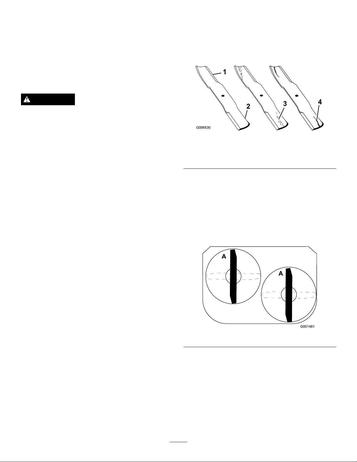
InspectingtheBlades
ServiceInterval:Beforeeachuseordaily
1.Inspectthecuttingedges(Figure46).Iftheedges
arenotsharporhavenicks,removeandsharpenthe
blades.RefertoSharpeningtheBlades.
Figure46
1.CuttingEdge3.Wear/slotformingin
curvedarea
2.Sail4.Crackinthecurvedarea
BeforeInspectingorServicingthe
Blades
Parkthemachineonalevelsurface,disengagetheblade
controlbailandsettheparkingbrake.Turntheignition
keytooff.Removethekeyanddisconnectthespark
plugwire(s)fromthesparkplug(s).
2.Inspecttheblades,especiallythecurvedarea
(Figure46).Ifyounoticeanydamage,wear,or
aslotforminginthisarea(item
immediatelyinstallanewblade.
3.inFigure46),
CheckingforBentBlades
1.Rotatethebladesuntiltheendsfaceforwardand
backward(
Figure47).
Figure47
36
Page 37

Figure48
2.Measurefromalevelsurfacetothecuttingedge,
positionA,oftheblades(Figure49).Notethis
dimension.
Figure49
1.Measurefromthecuttingedgetoalevelsurface
3.Rotatetheoppositeendsofthebladesforward.
4.Measurefromalevelsurfacetothecuttingedgeof
thebladesatthesamepositionasinstep
1.The
differencebetweenthedimensionsobtainedinsteps
1and2mustnotexceed1/8inch(3mm).Ifthis
dimensionexceeds1/8inch(3mm),thebladeis
bentandmustbereplaced.RefertoRemovingthe
BladesandInstallingtheBlades.
WARNING
Abladethatisbentordamagedcouldbreak
apartandcouldseriouslyinjureorkillyouor
bystanders.
•Alwaysreplacebentordamagedbladewith
anewblade.
•Neverleorcreatesharpnotchesinthe
edgesorsurfacesofblade.
Figure50
1.Blade
2.Bladebolt5.Thinwasher
3.Curvedwasher
4.Spacer
6.Nut
SharpeningtheBlades
1.Usealetosharpenthecuttingedgeatbothends
oftheblade(
Thebladeretainsitsbalanceifthesameamountof
materialisremovedfrombothcuttingedges.
Figure51).Maintaintheoriginalangle.
RemovingtheBlades
Replacethebladesifyouhitasolidobjectorifthe
bladesareoutofbalanceorbent.T oensureoptimum
performanceandcontinuedsafetyconformanceof
themachine,usegenuineT ororeplacementblades.
Replacementbladesmadebyothermanufacturersmay
resultinnon-conformancewithsafetystandards.
1.Holdthebladeboltwithawrench.
2.Removethenut,bladebolt,curvedwasher,blade,
spacers,andthinwasherfromthespindle(
Figure50).
Figure51
1.Sharpenatoriginalangle
2.Checkthebalanceofthebladebyputtingitona
bladebalancer(Figure52).Ifthebladestaysina
horizontalposition,thebladeisbalancedandcanbe
used.Ifthebladeisnotbalanced,lesomemetaloff
37
Page 38

theendofthesailareaonly(Figure52).Repeatthis
procedureuntilthebladeisbalanced.
Figure52
1.Blade2.Balancer
InstallingtheBlades
1.Placethebladeontotheboltandoverthecurved
washer.Selectthepropernumberofspacer(s)for
theheight-of-cut,andslidetheboltintothespindle
(Figure50).
Important:Thecurvedpartoftheblademust
pointupwardtowardtheinsideofthemowerto
ensurepropercutting.
2.Installtheremainingspacer(s)andsecurethemwith
athinwasherandanut(Fig.
3.Torquethebladeboltto75-80ft-lb(101-108N-m).
Figure50).
AdjustingtheBladeBrake
1.DisengagethePTO ,turntheignitionkeytooff,and
removethekey.
2.Waitforallmovingpartstostopbeforeleavingthe
operatingpositionandthensettheparkingbrake.
3.Ifnecessary,adjustthespringmountingboltssothat
thebladebrakepadrubsagainstbothsidesofthe
pulleygroove(
Figure53).
Figure53
1.Springmountingbolts3.1/8-3/16inch(3mm-5mm)
2.Bladebrakepad
ReplacingtheGrassDeector
WARNING
Anuncovereddischargeopeningcouldallowthe
lawnmowertothrowobjectsintheoperator'sor
bystander'sdirectionandresultinseriousinjuryor
death.Also,contactwiththebladecouldoccur.
Neveroperatethelawnmowerunlessyouinstall
acoverplate,amulchplate,oragrasschuteand
catcher.
1.Removethelocknut,bolt,springandspacerholding
thedeectortothepivotbrackets(Figure54).
Removedamagedorworngrassdeector.
4.Adjustthenutattheendofthebladebrakeroduntil
thereis1/8-3/16inch(3mm-5mm)betweenthe
nutandspacer(Figure53).
5.Engagetheblades.Ensurethebladebrakepadno
longercontactsthepulleygroove.
38
Page 39

Figure54
1.Bolt
2.Spacer6.GrassDeector
3.Locknut
4.Spring8.Jhookendofspring
5.Springinstalled
7.Lendofspring,place
behinddeckedgebefore
installingbolt
2.Placespacerandspringontograssdeector.Place
theLendofspringbehinddeckedge.
Note:MakesuretheLendofspringisinstalled
behinddeckedgebeforeinstallingtheboltasshown
Figure54.
in
3.Installboltandnut.PlacetheJhookendofspring
aroundgrassdeector(Figure54).
Important:Thegrassdeectormustbeable
torotate.Liftthedeectoruptothefullopen
positionandensurethatitrotatesintothefull
downposition.
Storage
CleaningandStorage
1.Disengagethepowertakeoff(PTO),settheparking
brake,andturntheignitionkeytooff.Removethe
key.
2.Removegrassclippings,dirt,andgrimefromthe
externalpartsoftheentiremachine,especiallythe
engine.Cleandirtandchafffromtheoutsideofthe
engine'scylinderheadnsandblowerhousing.
Important:Youcanwashthemachinewith
milddetergentandwater.Donotpressurewash
themachine.Avoidexcessiveuseofwater,
especiallyneartheshiftleverplate,andengine.
3.Checkthebrake;refertoServicingtheBrakein
BrakeMaintenance(page28).
4.Servicetheaircleaner;refertoServicingtheAir
Cleaner.
5.Greasethemachine;refertoGreasingand
LubricationinLubrication(page21).
6.Changethecrankcaseoil;refertoServicingthe
Enginein.
7.Checkthetirepressure;refertoCheckingtheTire
PressureinDriveSystemMaintenance(page27).
8.Forlong-termstorage:
A.Addstabilizer/conditioneradditivetofuelinthe
tank.
B.Runenginetodistributeconditionedfuelthrough
thefuelsystem(5minutes).
C.Stopengine,allowtocoolanddrainthefuel
tank;refertoServicingtheFuelTankin
FuelSystemMaintenance(page25),oroperate
engineuntilitstops.
D.Restartengineandrununtilitstops.Repeat,on
Chokeuntilenginewillnotrestart.
E.Disposeoffuelproperly.Recycleasperlocal
codes.
Note:Donotstorestabilizer/conditioned
gasolineover90days.
9.Removethesparkplug(s)andcheckitscondition;
refertoServicingtheSparkPlug.Withthe
sparkplug(s)removedfromtheengine,pour
twotablespoonsofengineoilintothesparkplug
hole.Nowusethestartertocranktheengineand
distributetheoilinsidethecylinder.Installthespark
plug(s).Donotinstallthewireonthesparkplug(s).
10.Checkandtightenallbolts,nuts,andscrews.Repair
orreplaceanypartthatisdamagedordefective.
39
Page 40

11.Paintallscratchedorbaremetalsurfaces.Paintis
availablefromyourAuthorizedServiceDealer.
12.Storethemachineinaclean,drygarageorstorage
area.Removethekeyfromtheignitionswitchand
keepitinamemorableplace.Coverthemachineto
protectitandkeepitclean.
40
Page 41

Troubleshooting
Problem
Enginewillnotstart,startshard,orfails
tokeeprunning.
Enginelosespower.
PossibleCauseCorrectiveAction
1.Fueltankisempty.
2.Fuelshutoffvalveisclosed.2.Openthefuelshutoffvalve.
3.Chokeisnoton.
4.Aircleanerisdirty.
5.Sparkplugwireislooseor
disconnected.
6.Sparkplugispitted,fouled,orthegap
isincorrect.
7.Dirtinthefuellter.7.Replacethefuellter.
8.Dirt,water,orstalefuelisinthefuel
system.
1.Engineloadisexcessive.1.Reducethegroundspeed.
2.Aircleanerisdirty.
3.Oillevelinthecrankcaseislow.
4.Coolingnsandairpassagesunder
theengineblowerhousingareplugged.
5.Sparkplugispitted,fouled,orthegap
isincorrect.
6.Ventholeinthefuelcapisplugged.6.Cleanorreplacethefuelcap.
7.Dirtinthefuellter.7.Replacethefuellter.
8.Dirt,water,orstalefuelisinthefuel
system.
1.Fillthefueltankwithgasoline.
3.Movethethrottlelevertochoke
position.
4.Cleanorreplacetheaircleaner
element.
5.Installthewireonsparkplug.
6.Installanew,correctlygappedspark
plug.
8.ContactanAuthorizedServiceDealer.
2.Cleantheaircleanerelement.
3.Addoiltothecrankcase.
4.Removetheobstructionfromthe
coolingnsandairpassages.
5.Installanew,correctlygappedspark
plug.
8.ContactanAuthorizedServiceDealer.
Engineoverheats.
Machinedoesnotdrive.
Abnormalvibration.
Unevencuttingheight.
1.Engineloadisexcessive.1.Reducethegroundspeed.
2.Oillevelinthecrankcaseislow.
3.Coolingnsandairpassagesunder
theengineblowerhousingareplugged.
1.Shiftleverisinneutral.1.Moveshiftlevertoadrivegearposition.
2.Tractionbeltisworn,looseorbroken.
3.Tractionbeltisoffapulley.3.Changethebelt.
4.Brokenormissingidlerspring.4.Replacethespring.
1.Cuttingblade(s)is/arebentor
unbalanced.
2.Blademountingboltisloose.2.Tightentheblademountingbolt.
3.Enginemountingboltsareloose.3.Tightentheenginemountingbolts.
4.Looseenginepulley ,idlerpulley,or
bladepulley .
5.Enginepulleyisdamaged.
6.Bladespindleisbent.
1.Blade(s)notsharp.1.Sharpentheblade(s).
2.Cuttingblade(s)is/arebent.2.Installnewcuttingblade(s).
3.Mowerisnotlevel.
4.Undersideofmowerisdirty.4.Cleantheundersideofthemower.
5.Tirepressureisnotcorrect.5.Adjustthetirepressure.
6.Bladespindlebent.
2.Addoiltothecrankcase.
3.Removetheobstructionfromthe
coolingnsandairpassages.
2.Changethebelt.
1.Installnewcuttingblade(s).
4.Tightentheappropriatepulley.
5.ContactanAuthorizedServiceDealer.
6.ContactanAuthorizedServiceDealer.
3.Levelthemowerfromside-to-sideand
front-to-rear.
6.ContactanAuthorizedServiceDealer.
41
Page 42

Problem
PossibleCauseCorrectiveAction
Bladesdonotrotate.
1.Mowerdeckbeltiswornorloose.
2.Mowerdeckbeltisbroken.2.Installanewdeckbelt.
3.Mowerdeckbeltisoffpulley.3.Inspectthebeltandreplaceifdamaged.
4.Brokenormissingidlerspring.4.Replacethespring.
1.Checkthebelttension.
Checkthepulleysandidlersandadjust
thebelttension.
42
Page 43

Schematics
ElectricalSchematic(Rev.A)
43
Page 44

TheToroTotalCoverageWarranty
ALimitedW arranty(seewarrantyperiodsbelow)
Landscape
Contractor
Equipment(LCE)
ConditionsandProductsCovered
TheToroCompanyanditsafliate,ToroWarrantyCompany,pursuantto
anagreementbetweenthem,jointlypromisetotheoriginalpurchaser
torepairtheToroProductslistedbelowifdefectiveinmaterialsor
workmanship.
Thefollowingtimeperiodsapplyfromthedateofpurchasebytheoriginal
owner:
ProductsWarrantyPeriod
AllMowers
•Engine**
•Battery1year
•Attachments1year
Mid-SizeWalk-BehindMowers
GrandStand
•Frame
ZMaster
•Engine
•Frame
ZMaster
•Frame
*Whicheveroccursrst.
**SomeenginesusedonToroLCEProductsarewarrantedbytheenginemanufacturer .
***LifetimeFrameWarranty-Ifthemainframe,consistingofthepartsweldedtogethertoformthe
tractorstructurethatothercomponentssuchastheenginearesecuredto,cracksorbreaksin
normaluse,itwillberepairedorreplacedunderwarrantyatnocostforpartsandlabor .Frame
failureduetomisuseorabuseandfailureorrepairrequiredduetorustorcorrosionarenotcovered.
Thiswarrantyincludesthecostofpartsandlabor,butyoumustpay
transportationcosts.
TM
Mowers5yearsor1,200hours*
®
Z400,Z500Mowers
®
G3Mowers5yearsor1,200hours*
2years
2years
Lifetime(originalowneronly)***
4yearsor1,200hours*
2years**
Lifetime(originalowneronly)***
Lifetime(originalowneronly)***
InstructionsforObtainingWarrantyService
IfyouthinkthatyourT oroProductcontainsadefectinmaterialsor
workmanship,followthisprocedure:
1.ContactanyAuthorizedT oroServiceDealertoarrangeserviceattheir
dealership.T olocateadealerconvenienttoyou,refertotheY ellow
Pagesofyourtelephonedirectory(lookunder“LawnMowers”)or
accessourwebsiteatwww.Toro.com.Y oumayalsocallthenumbers
listedinitem#3tousethe24-hourToroDealerlocatorsystem.
2.Bringtheproductandyourproofofpurchase(salesreceipt)tothe
ServiceDealer.Thedealerwilldiagnosetheproblemanddetermine
ifitiscoveredunderwarranty.
3.IfforanyreasonyouaredissatisedwiththeServiceDealer’s
analysisorwiththeassistanceprovided,contactusat:
RLCCustomerCareDepartment
ToroWarrantyCompany
811 1LyndaleAvenueSouth
Bloomington,MN55420-1196
888-865-5676(U.S.Customers)
888-865-5691(Canadacustomers)
OwnerResponsibilities
YoumustmaintainyourT oroProductbyfollowingthemaintenance
proceduresdescribedintheOperator'sManual.Suchroutine
maintenance,whetherperformedbyadealerorbyyou,isatyourexpense.
ItemsandConditionsNotCovered
Thereisnootherexpresswarrantyexceptforspecialemission
systemandenginewarrantycoverageonsomeproducts.
Thisexpresswarrantydoesnotcoverthefollowing:
•Costofregularmaintenanceserviceorwearparts,suchaslters,
fuel,lubricants,tune-upparts,bladesharpening,brakeandclutch
adjustments.
•Anyproductorpartwhichhasbeenalteredormisusedandrequires
replacementorrepairduetonormalwear,accidents,orlackof
propermaintenance.
•Repairsnecessaryduetoimproperfuel,contaminantsinthefuel
system,orfailuretoproperlypreparethefuelsystempriortoany
periodofnon-useoverthreemonths.
•Pickupanddeliverycharges.
GeneralConditions
Allrepairscoveredbythesewarrantiesmustbeperformedbyan
AuthorizedToroServiceDealerusingToroapprovedreplacementparts.
NeitherTheToroCompanynorToroWarrantyCompanyisliablefor
indirect,incidentalorconsequentialdamagesinconnectionwiththe
useoftheT oroProductscoveredbythiswarranty,includingany
costorexpenseofprovidingsubstituteequipmentorserviceduring
reasonableperiodsofmalfunctionornon-usependingcompletion
ofrepairsunderthiswarranty.
Allimpliedwarrantiesofmerchantability(thattheproductistfor
ordinaryuse)andtnessforuse(thattheproductistforaparticular
purpose)arelimitedtothedurationoftheexpresswarranty
Somestatesdonotallowexclusionsofincidentalorconsequential
damages,orlimitationsonhowlonganimpliedwarrantylasts,so
theaboveexclusionsandlimitationsmaynotapplytoyou.
Thiswarrantygivesyouspeciclegalrights,andyoumayalsohaveother
rightswhichvaryfromstatetostate.
CountriesOtherthantheUnitedStatesorCanada
CustomerswhohavepurchasedToroproductsoutsidetheUnitedStatesorCanadashouldcontacttheirT oroDistributor(Dealer)toobtainguarantee
policiesforyourcountry,province,orstate.IfforanyreasonyouaredissatisedwithyourDistributor'sserviceorhavedifcultyobtainingguarantee
information,contacttheToroimporter.Ifallotherremediesfail,youmaycontactusatT oroWarrantyCompany .
374-0252RevA
 Loading...