

Page 1
FormNo.3391-556RevB
G017536
CommercialWalk-BehindMower
FixedDeck,PistolGrip,GearDrivewith32in,
36inor48inCuttingUnit
ModelNo.30632—SerialNo.315000001andUp
ModelNo.30634—SerialNo.315000001andUp
ModelNo.30638—SerialNo.315000001andUp
ModelNo.39634—SerialNo.315000001andUp
ModelNo.39638—SerialNo.315000001andUp
Registeratwww.T oro.com.
OriginalInstructions(EN)
*3391-556*B
Page 2
WARNING
CALIFORNIA
Proposition65Warning
Thisproductcontainsachemical
orchemicalsknowntotheStateof
Californiatocausecancer,birthdefects,
orreproductiveharm.
Theengineexhaustfromthisproduct
containschemicalsknowntotheStateof
Californiatocausecancer,birthdefects,
orotherreproductiveharm.
Important:Thisengineisnotequippedwith
asparkarrestermufer.Itisaviolationof
CaliforniaPublicResourceCodeSection4442to
useoroperatetheengineonanyforest-covered,
brush-covered,orgrass-coveredland.Other
statesorfederalareasmayhavesimilarlaws.
WARNING
Removingstandardoriginalequipmentparts
andaccessoriesmayalterthewarranty,
traction,andsafetyofthemachine.Failureto
useoriginalT oropartscouldcauseserious
injuryordeath.Makingunauthorizedchanges
totheengine,fuelorventingsystem,may
violateEPAandCARBregulations.
Replaceallpartsincluding,butnotlimited
to,tires,belts,blades,andfuelsystem
componentswithoriginalToroparts.
Theenclosedengineowner’smanualissupplied
forinformationregardingtheUSEnvironmental
ProtectionAgency(EPA)andtheCaliforniaEmission
ControlRegulationofemissionsystems,maintenance,
andwarranty.Replacementsmaybeorderedthrough
theenginemanufacturer.
YoumaycontactT orodirectlyatwww.Toro.comfor
productandaccessoryinformation,helpndinga
dealer,ortoregisteryourproduct.
Wheneveryouneedservice,genuineToroparts,or
additionalinformation,contactanAuthorizedService
DealerorToroCustomerServiceandhavethemodel
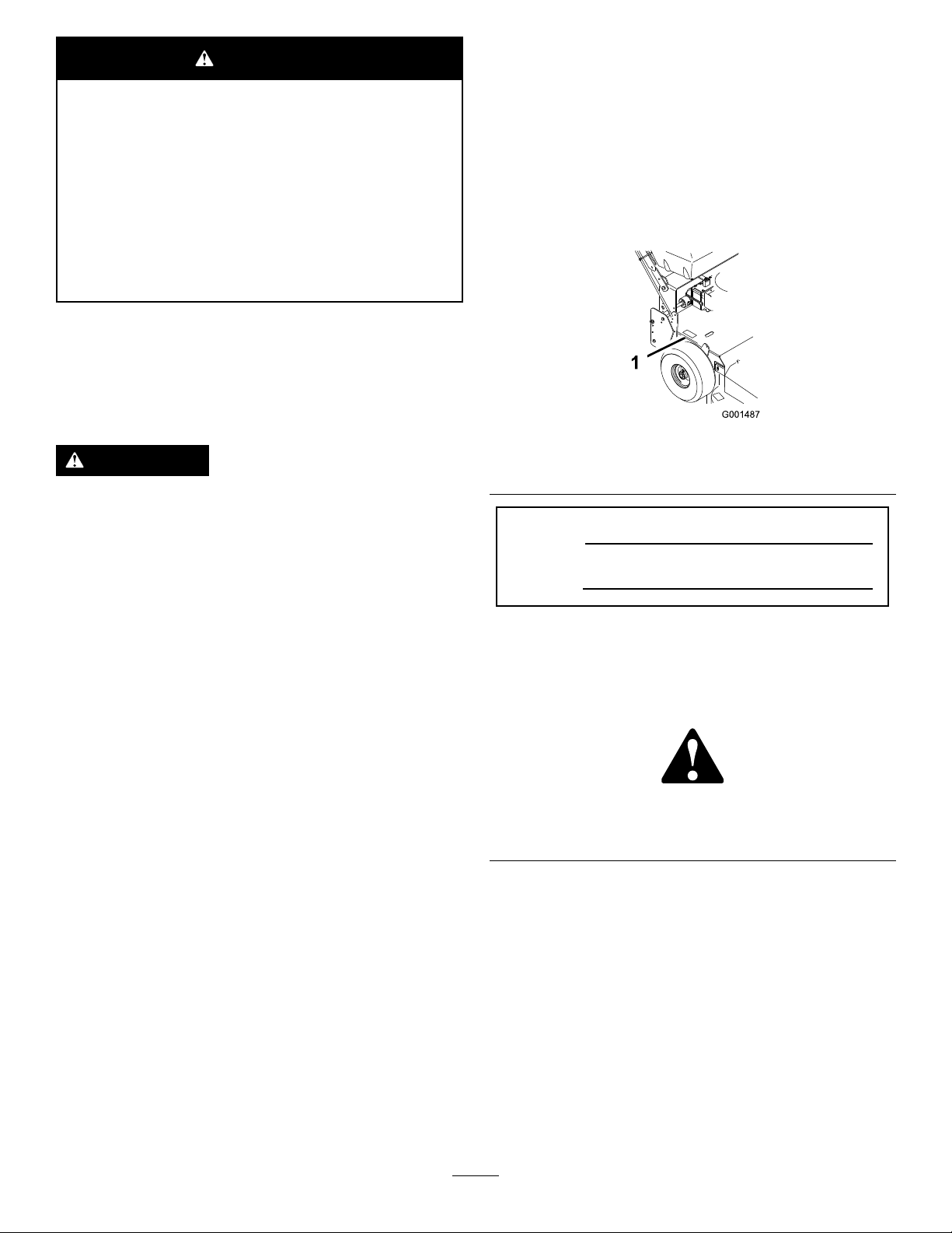
andserialnumbersofyourproductready.Figure1
identiesthelocationofthemodelandserialnumbers
ontheproduct.Writethenumbersinthespace
provided.
g001487
Figure1
1.Modelandserialnumberlocation
ModelNo.
SerialNo.
Thismanualidentiespotentialhazardsandhas
safetymessagesidentiedbythesafetyalertsymbol
(Figure2),whichsignalsahazardthatmaycause
seriousinjuryordeathifyoudonotfollowthe
recommendedprecautions.
g000502
Figure2
1.Safetyalertsymbol
Introduction
Thisrotary-blade,lawnmowerisintendedtobe
usedbyresidentialhomeownersorprofessional,
hiredoperators.Itisdesignedprimarilyforcutting
grassonwell-maintainedlawnsonresidential
orcommercialproperties.Itisnotdesignedfor
cuttingbrushorforagriculturaluses.
Readthisinformationcarefullytolearnhowtooperate
andmaintainyourproductproperlyandtoavoid
injuryandproductdamage.Y ouareresponsiblefor
operatingtheproductproperlyandsafely .
©2017—TheToro®Company
8111LyndaleAvenueSouth
Bloomington,MN55420
Thismanualuses2wordstohighlightinformation.
Importantcallsattentiontospecialmechanical
informationandNoteemphasizesgeneralinformation
worthyofspecialattention.
2
Contactusatwww.Toro.com.
PrintedintheUSA
AllRightsReserved
Page 3

Contents
Safety.......................................................................4
SafeOperatingPractices....................................4
ToroMowerSafety..............................................5
SlopeIndicator...................................................7
SafetyandInstructionalDecals..........................8
ProductOverview....................................................11
Controls............................................................11
Specications..................................................12
Attachments/Accessories.................................12
Operation................................................................12
AddingFuel......................................................12
UsingFuelStabilizer/Conditioner.....................13
CheckingtheEngine-OilLevel..........................13
FillingtheFuelTank..........................................13
PuttingSafetyFirst...........................................13
OperatingtheParkingBrakeandNeutral
Locks............................................................14
StartingandStoppingtheEngine......................14
OperatingtheBlade-Control(PTO)
Lever.............................................................15
TheSafety-InterlockSystem.............................15
DrivingForwardorBackward............................16
StoppingtheMower..........................................16
TransportingtheMachine.................................17
SideDischargingorMulchingthe
Grass............................................................17
AdjustingtheWheel-Drive-BeltT ension............17
AdjustingtheHeightofCut...............................18
AdjustingtheFlowBafe..................................19
PositioningtheFlowBafe................................19
AdjustingtheHandleHeight.............................20
Height-of-CutChart..........................................22
Maintenance...........................................................23
RecommendedMaintenanceSchedule(s)...........23
Lubrication..........................................................24
LubricatingtheMachine....................................24
LubricatingtheCasterandWheel
Bearings........................................................24
GreasingtheTransmissionCouplers................24
GreasingtheMower-BeltIdler..........................24
EngineMaintenance...........................................25
ServicingtheAirCleaner..................................25
ServicingtheEngineOil....................................25
ServicingtheSparkPlugs.................................27
FuelSystemMaintenance...................................28
ServicingtheFuelSystem................................28
DriveSystemMaintenance..................................30
CheckingtheTirePressure...............................30
CoolingSystemMaintenance..............................31
CleaningtheAir-intakeScreen.........................31
CleaningtheCoolingSystem............................31
BrakeMaintenance.............................................32
ServicingtheBrakes.........................................32
BeltMaintenance................................................33
CheckingtheBelts............................................33
ReplacingtheTractionDriveBelt......................33
ReplacingtheDriveBelt...................................33
ReplacingtheMowerBelt.................................33
AdjustingtheMowerBeltT ension.....................35
ControlsSystemMaintenance.............................38
AdjustingtheControlRods...............................38
MowerDeckMaintenance....................................39
ServicingtheCuttingBlades.............................39
AdjustingtheBladeBrake.................................41
ReplacingtheGrassDeector..........................42
Storage...................................................................43
CleaningandStorage.......................................43
Troubleshooting......................................................44
Schematics.............................................................46
3
Page 4

Safety
Note:Theadditionofattachmentsmadeby
othermanufacturersthatdonotmeetAmerican
NationalStandardsInstitutecerticationwillcause
noncomplianceofthismachine.
Improperlyusingormaintainingthemachinecan
resultininjury.Toreducethepotentialforinjury ,
complywiththesesafetyinstructionsandalways
payattentiontothesafetyalertsymbol,which
meansCaution,Warning,orDanger—personal
safetyinstruction.Failuretocomplywiththe
instructionmayresultinpersonalinjuryordeath.
Thisproductiscapableofamputatinghandsand
feetandofthrowingobjects.Alwaysfollowallsafety
instructionstoavoidseriousinjuryordeath.
SafeOperatingPractices
ThefollowinginstructionsareadaptedfromANSI
B71.4-2012.
Training
•ReadtheOperator'sManualandothertraining
material.Iftheoperator(s)ormechanic(s)cannot
readorunderstandtheinformationitistheowner's
responsibilitytoexplainthismaterialtothem.
•Becomefamiliarwiththesafeoperationofthe
equipment,operatorcontrols,andsafetysigns.
•Alloperatorsandmechanicsshouldbetrained.
Theownerisresponsiblefortrainingtheusers.
•Neverletchildrenoruntrainedpeopleoperateor
servicetheequipment.Localregulationsmay
restricttheageoftheoperator.
•Theowner/usercanpreventandisresponsible
foraccidentsorinjuriesoccurringtopeopleor
damagetoproperty.
Preparation
•Evaluatetheterraintodeterminewhataccessories
andattachmentsareneededtoproperlyand
safelyperformthejob.Useonlyaccessoriesand
attachmentsapprovedbythemanufacturer.
•Wearappropriateclothingincludinghardhat,
substantial,slip-resistantfootwear,safetyglasses,
andhearingprotection.Longhair,looseclothing,
orjewelrymaygettangledinmovingparts.
•Inspecttheareawheretheequipmentistobe
usedandremoveallobjectssuchasrocks,toys,
andwire,whichcanbethrownbythemachine.
•Checkthatoperator'spresencecontrols,safety
switches,andshieldsareattachedandfunctioning
properly.Donotoperateunlesstheyare
functioningproperly.
Operation
•Lightningcancausesevereinjuryordeath.If
lightningisseenorthunderisheardinthearea,do
notoperatethemachine;seekshelter.
•Neverrunanengineinanenclosedarea.
•Operatethemachineonlyingoodlight,keeping
awayfromholesandhiddenhazards.
•Besurethatalldrivesareinneutralandthe
parkingbrakeisengagedbeforestartingthe
engine.Starttheengineonlyfromtheoperator's
position.
•Besureofyourfootingwhileusingthismachine,
especiallywhenbackingup.Walk;donotrun.
Neveroperateonwetgrass.Reducedfooting
couldcauseslipping.
•Slowdownanduseextracareonhillsides.Be
suretotravelsidetosideonhillsides.Turf
conditionscanaffectthestabilityofthemachine.
Usecautionwhileoperatingneardrop-offs.
•Slowdownandusecautionwhenmakingturns
andwhenchangingdirectiononslopes.
•Neverraisethedeckwiththebladesrunning.
•NeveroperatewiththePTOshieldorotherguards
notsecurelyinplace.Besureallinterlocksare
attached,adjustedproperly,andfunctioning
properly.
•Neveroperatewiththedischargedeectorraised,
removedoraltered,unlessyouareusingagrass
catcher.
•Donotchangetheenginegovernorsettingor
overspeedtheengine.
•Stoponlevelground,disengagedrives,engage
theparkingbrake(ifprovided),andshutoffthe
enginebeforeleavingtheoperator'spositionfor
anyreason,includingemptyingthecatchersor
uncloggingthechute.
•Stoptheequipmentandinspecttheblades
afterstrikingobjectsorifanabnormalvibration
occurs.Makenecessaryrepairsbeforeresuming
operation.
•Keephandsandfeetawayfromthecuttingunit.
•Lookbehindanddownbeforebackinguptobe
sureofaclearpath.
•Nevercarrypassengersonthemachine.
•Keeppetsandbystandersaway .
•Slowdownandusecautionwhenmakingturns
andcrossingroadsandsidewalks.Stopthe
bladesifyouarenotmowing.
4
Page 5

•Beawareofthemowerdischargedirectionand
donotpointitatanyone.
•Donotoperatethemachinewhileill,tired,or
undertheinuenceofalcoholordrugs.
•Usecarewhenloadingorunloadingthemachine
intoorfromatrailerortruck.
•Usecarewhenapproachingblindcorners,shrubs,
trees,orotherobjectsthatmayobscurevision.
•Usefull-widthrampsforloadingmachineinto
trailerortruck.
•Tiethemachinedownsecurelyusingstraps,
chains,cable,orropes.Bothfrontandrearstraps
shouldbedirecteddownandoutwardfromthe
machine.
ToroMowerSafety
MaintenanceandStorage
•Disengagedrives,settheparkingbrake,stop
theengineandremovethekeyordisconnect
thespark-plugwire.Waitforallmovementto
stopbeforeadjusting,cleaning,orrepairingthe
machine.
•Cleangrassanddebrisfromthecuttingunit,the
drives,themufers,andtheenginetohelpprevent
res.Cleanupoilorfuelspills.
•Lettheenginecoolbeforestoring,anddonot
storeitnearaame.
•Shutoffthefuelwhilestoringortransportingthe
machine.Donotstorefuelnearamesordrainit
indoors.
•Parkthemachineonlevelground.Settheparking
brake.Neverallowuntrainedpersonneltoservice
themachine.
•Usejackstandstosupportcomponentswhen
required.
•Carefullyreleasepressurefromcomponentswith
storedenergy.
•Disconnectthebatteryorthespark-plugwire
beforemakinganyrepairs.Disconnectthe
negativeterminalrstandthepositivelast.
Connectthepositiverstandnegativelast.
•Usecarewhencheckingtheblades.Wrapthe
blade(s)orweargloves,andusecautionwhen
servicingthem.Onlyreplaceblades.Never
straightenorweldthem.
•Keephandsandfeetawayfrommovingparts.If
possible,donotmakeadjustmentswiththeengine
running.
•Keepallpartsingoodworkingconditionandall
hardwaretightened.Replaceallwornordamaged
decals.
•Tobestprotectyourinvestmentandmaintain
optimalperformanceofyourToroequipment,count
onT orogenuineparts.Whenitcomestoreliability ,
Torodeliversreplacementpartsdesignedtothe
exactengineeringspecicationsofourequipment.
Forpeaceofmind,insistonT orogenuineparts.
Hauling
•Usecarewhenloadingorunloadingthemachine
intoatrailerortruck.
Thefollowinglistcontainssafetyinformationspecic
toToroproductsandothersafetyinformationyou
mustknow.
Thisproductisdesignedforcuttingandrecycling
grassor,whenequippedwithagrassbagger,for
catchingcutgrass.Anyuseforpurposesotherthan
thesecouldprovedangeroustoyouandbystanders.
GeneralOperation
•Besurethattheareaisclearofotherpeople
beforemowing.Stopthemachineifanyoneenters
thearea.
•Donottouchequipmentorattachmentpartswhich
maybehotfromoperation.Allowthemtocool
beforeattemptingtomaintain,adjust,orservice
them.
•UseonlyT oroapprovedattachments.The
warrantymaybevoidedifyouusethemachine
withunapprovedattachments.
•Checkcarefullyforoverheadclearances(i.e.
branches,doorways,electricalwires)before
operatingthemachineunderanyobjects,anddo
notcontactthem.
SlopeOperation
Allslopesandrampsrequireextracaution.Ifyoufeel
uneasyonaslope,donotmowit.
•Removeobstaclessuchasrocks,treelimbs,etc.
fromthemowingarea.
•Watchforholes,ruts,orbumps.Tallgrasscan
hideobstacles.
•Usecautionneardrop-offs,ditches,or
embankments.Themachinecouldsuddenlyturn
overifawheelgoesovertheedgeofacliffor
ditch,orifanedgecavesin.
•Useextracarewithgrasscatchersorother
attachments.Thesecanchangethestabilityof
themachine.
•Keepallmovementonslopesslowandgradual.
Donotmakesuddenchangesinspeedor
direction.
•Mowslopessidetoside.
•Donotmowslopesgreaterthan20degrees.
5
Page 6

Service
•Neverstorethemachineorfuelcontainerinside
wherethereisanopename,suchasneara
waterheaterorfurnace.
•Keepnutsandboltstight,especiallytheblade
attachmentbolts.Keepequipmentingood
condition.
•Nevertamperwithsafetydevices.Checksafety
systemsforproperoperationbeforeeachuse.
•Useonlygenuinereplacementpartstoensurethat
originalstandardsaremaintained.
•Checkbrakeoperationfrequently.Adjustand
serviceasrequired.
6
Page 7
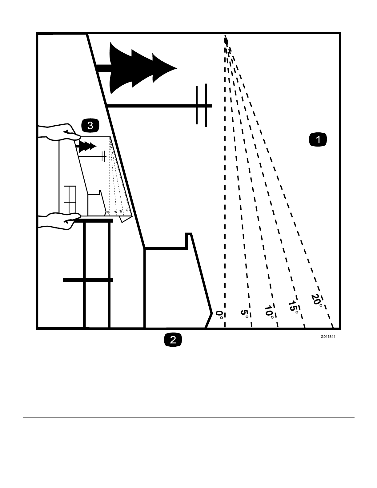
SlopeIndicator
G011841
Figure3
Thispagemaybecopiedforpersonaluse.
1.Themaximumslopeyoucansafelyoperatethemachineonis20degrees.Usetheslopecharttodeterminethedegreeofslope
ofhillsbeforeoperating.Donotoperatethismachineonaslopegreaterthan20degrees.Foldalongtheappropriateline
tomatchtherecommendedslope.
2.Alignthisedgewithaverticalsurface,atree,building,fencepole,etc.
3.Exampleofhowtocompareslopewithfoldededge.
7
g011841
Page 8
SafetyandInstructionalDecals
Safetydecalsandinstructionsareeasilyvisibletotheoperatorandarelocatednearanyarea
ofpotentialdanger.Replaceanydecalthatisdamagedorlost.
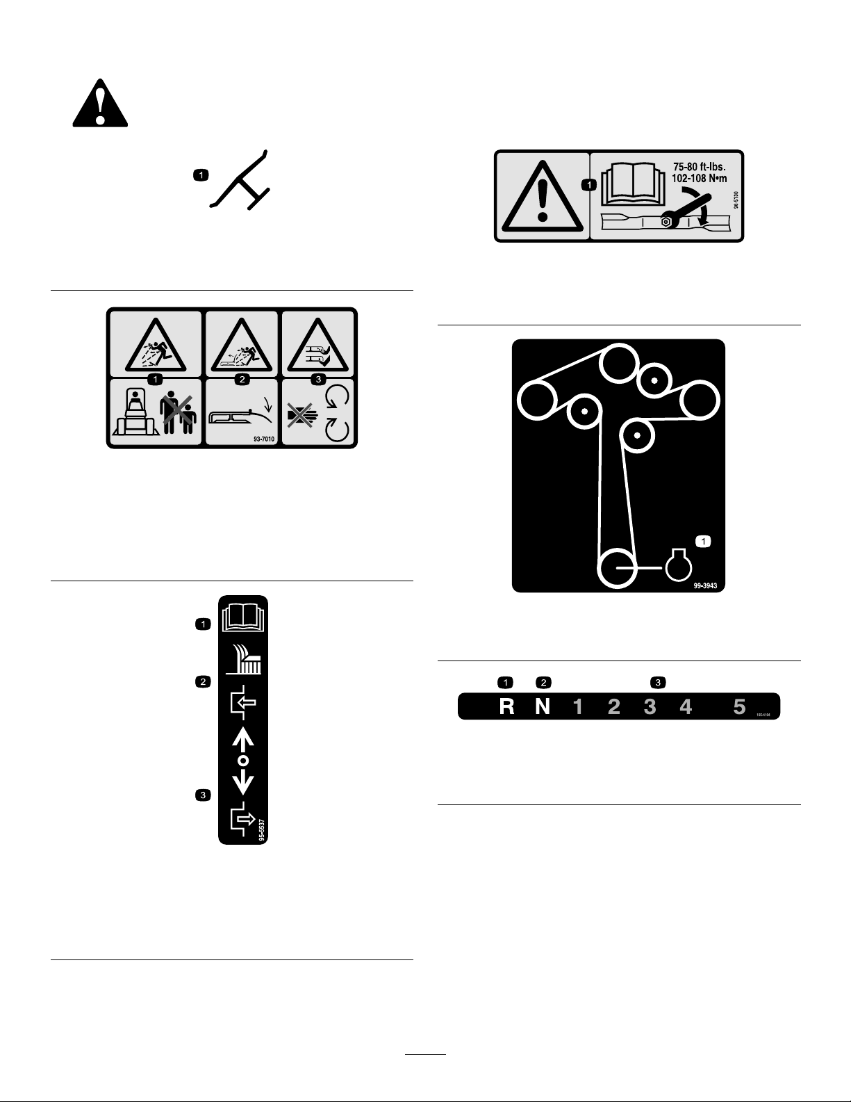
Manufacturer'sMark
1.Indicatesthebladeisidentiedasapartfromtheoriginal
machinemanufacturer.
93-7010
decaloemmarkt
decal98-5130
98-5130
1.Warning—readtheOperator'sManualforinstructionson
torquingthebladebolt/nutto75-80ft-lb(102-106N⋅m).
decal93-7010
1.Thrownobjecthazard—keepbystandersasafedistance
fromthemachine.
2.Thrownobjecthazard,mower—keepthedeectorinplace.
3.Cutting/dismembermentofhandorfoot—stayawayfrom
movingparts.
95-5537
1.ReadtheOperator's
Manualforinstructionson
operatingthecuttingblade
2.Pushforwardtoengage
3.Pullbacktodisengage
decal99-3943
99-3943
1.Engine
decal105-4104
105-4104
1.Reverse3.Transmissionspeeds
2.Neutral
decal95-5537(gear)
8
Page 9
decal112-9028
112-9028
1.Warning—stayawayfrommovingparts;keepallguardsin
place.
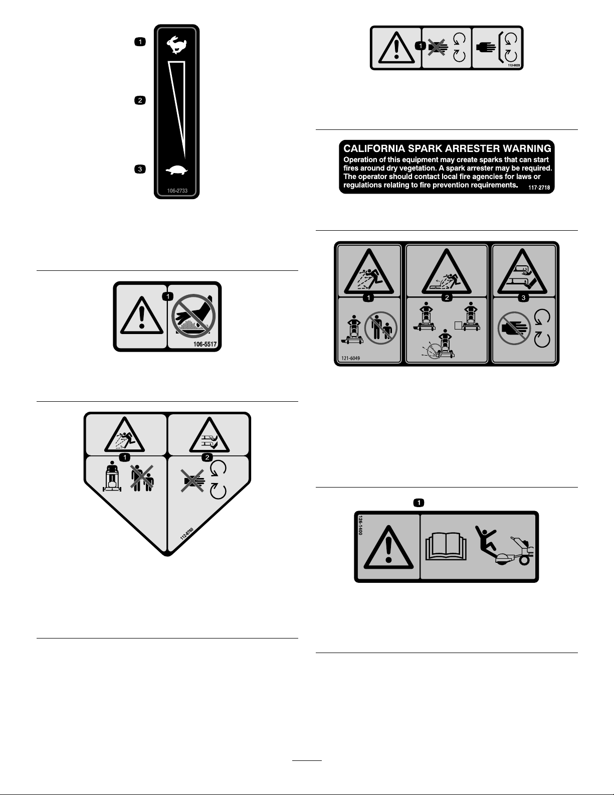
1.Fast
2.Continuousvariable
setting
1.Warning—donottouchthehotsurface.
decal106-2733
106-2733
117–2718
decal117-2718
3.Slow
decal106-5517
106-5517
decal121-6049
121-6049
1.Thrownobject
hazard—keepbystanders
awayfromthemachine.
2.Thrownobjecthazard,
mower—donotoperate
themowerwithguardsor
shieldsremoved.
3.Cutting/dismemberment
hazardofhandorfoot,
mowerblade—keephands
awayfrommovingparts.
112-8760
1.Thrownobjecthazard—keepbystandersasafedistance
fromthemachine.
2.Cutting/dismembermentofhandorfoot—stayawayfrom
movingparts.
decal112-8760
decal126-1400
126-1400
1.Warning-ReadtheOperator’smanual.UseonlyTororiding
attachments.Useofotherridingattachmentsmaycreatea
hazardousconditionresultingininjury.
9
Page 10
130-8371
1.Parkingbrake3.Neutrallock
2.Tractiondrive
decal130-8371
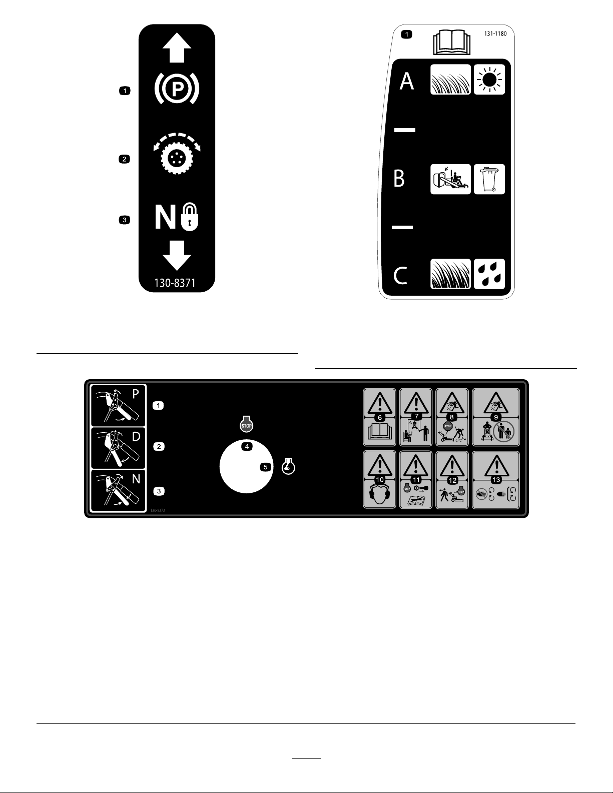
decal131-1180
131-1180
1.ReadtheOperator'sManual.(A)Short,lightgrass;dry
conditions;maximumdispersion;(B)Baggingsetting;(C)
Tall,densegrass;wetconditions;maximumgroundspeed
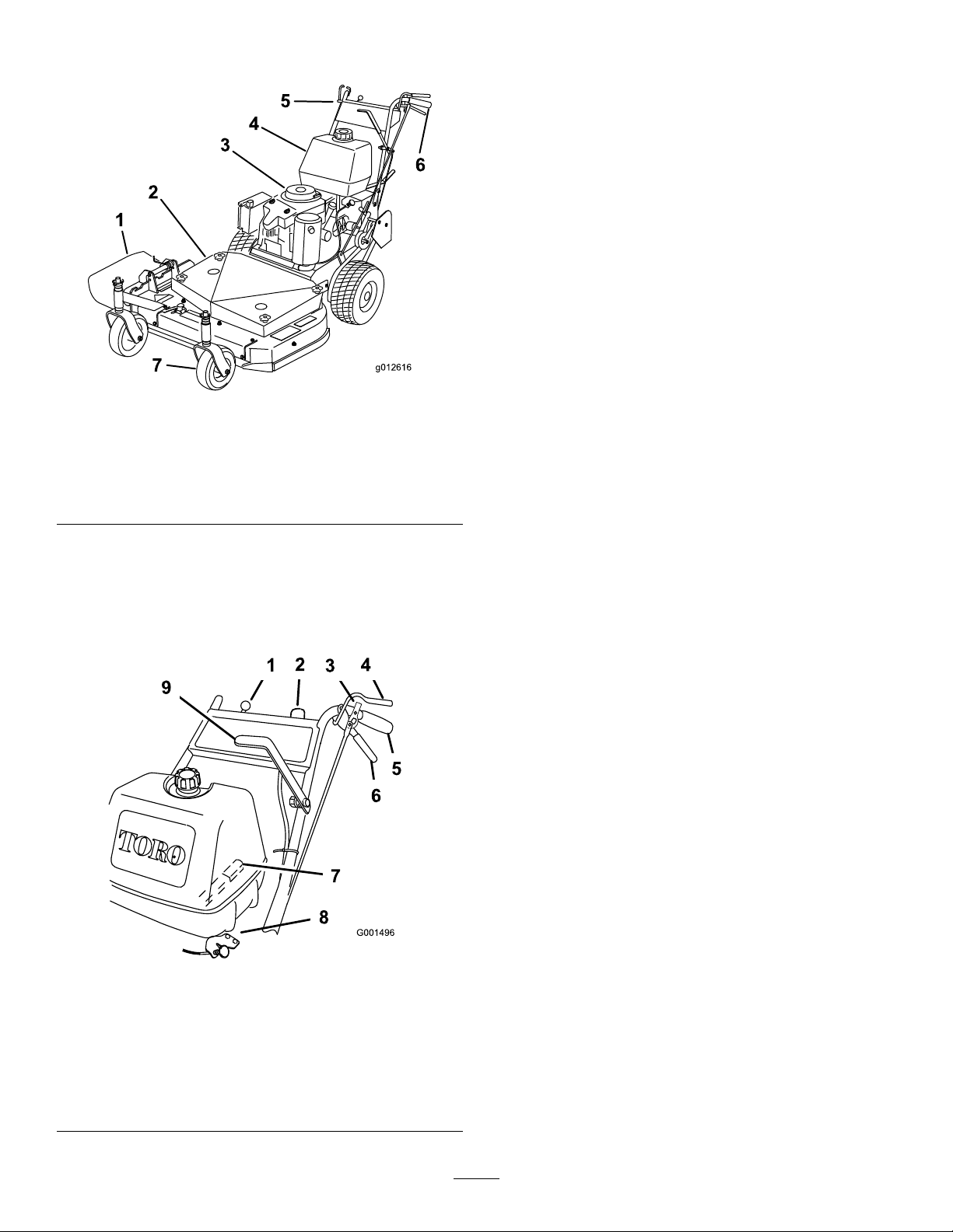
decal130-8373
130-8373
1.Parkingposition5.Engine—run9.Thrownobject
hazard—keepbystanders
awayfromthemachine.
2.Driveposition6.Warning—readthe
Operator'sManual.
3.Neutralposition7.Warning—donotoperate
themachinewithout
receivingpropertraining.
10.Warning—wearhearing
protection.
11.Warning—stoptheengine,
removethekeyfromthe
ignition,andreadthe
Operator'sManualbefore
servicingorperforming
maintenance.
4.Engine—stop8.Thrownobject
hazard—stoptheengine
andpickupanydebrisin
theareabeforeoperating
12.Warning,releasethebar
andensuretheenginehas
stoppedbeforewalking
awayfromthemachine.
themachine.
10
13.Warning—stayawayfrom
movingparts;keepall
guardsandshieldsinplace.
Page 11
ProductOverview
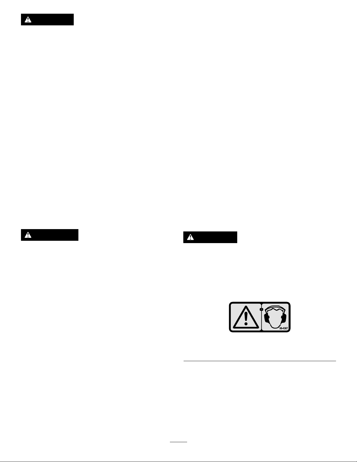
g012616
1
2
3
4
5
6
7
1.Sidedischarge5.Controls
2.Mowerdeck6.Handle
3.Recoil-starthandle
4.Fueltank
Figure4
7.Casterwheel
ThrottleControl
Thethrottlecontrolhas2positions:FastandSlow.
Operator-Presence-Control(OPC)
Levers
WhenyousqueezetheOPCleversagainstthe
handles,theOPCsystemsensesthattheoperatoris
inthenormaloperatingposition.Whenyourelease
theOPClevers,theOPCsystemsensesthatthe
operatorhasleftthenormaloperatingposition,and
thesystemwillstoptheengineifeitherthegear-shift
leverisnotintheNeutralpositionortheblade-control
(PTO)leverisengaged.
Gear-ShiftLever
g012616
Thetransmissionhas5forwardspeeds,neutral,and
reverse,andhasanin-lineshiftpattern.
Important:Donotshiftwhilethemachineis
moving,astransmissiondamagemayoccur.
DriveLevers
Controls
Becomefamiliarwithallthecontrols(Figure5)before
youstarttheengineandoperatethemachine.
1.Throttlecontrol6.Drivelever
2.Ignitionswitch
3.Neutral/parkingbrakelock8.Choke
4.Operator-presence-control
(OPC)lever
5.Handle
Figure5
7.Gear-shiftlever
9.Power-take-offlever(PTO)
Releasethedriveleverstoengagetheforward
tractionoperation.Squeezetheright-handdrivelever
toturnrightandtheleft-handdrivelevertoturnleft.
Neutral/Parking-BrakeLock
Squeezethedriveleversandmovethelocksrearward
forneutrallock.Squeezethedriveleversandmove
thelocksforwardtosettheparkingbrake.
Blade-ControlLever(PTO)
ThisleverisusedinconjunctionwiththeOPClevers
toengageordisengagethemowerdeckbeltand
drivethemowerblades.
Recoil-StartHandle
Pulltherecoil-starthandletostarttheengine(not
showninFigure5).
g001496
Fuel-ShutoffValve
Closethefuel-shutoffvalvewhentransportingor
storingthemachine.
IgnitionSwitch
Thisswitchisusedinconjunctionwiththerecoil
starterandhas2positions:RunandOff.
11
Page 12

Choke
Usethechoketostartacoldengine.
Operation
AddingFuel
Specications
Note:Specicationsanddesignaresubjectto
changewithoutnotice.
32-inchmowers:
Widthwithdeectordown116cm(46inches)
Length
Height
Weight
36-inchmowers:
Widthwithdeectordown118cm(47inches)
Length
Height
Weight
48-inchmowers:
Widthwithdeectordown161cm(63-1/2inches)
Length
Height
Weight
198cm(78inches)
104cm(41inches)
182kg(402lb)
203cm(80inches)
104cm(41inches)
210kg(462lb)
199cm(78inches)
104cm(41inches)
227kg(500lb)
•Forbestresults,useonlyclean,fresh(lessthan
30daysold),unleadedgasolinewithanoctane
ratingof87orhigher((R+M)/2ratingmethod).
•Ethanol:Gasolinewithupto10%ethanol
(gasohol)or15%MTBE(methyltertiarybutyl
ether)byvolumeisacceptable.EthanolandMTBE
arenotthesame.Gasolinewith15%ethanol
(E15)byvolumeisnotapprovedforuse.Never
usegasolinethatcontainsmorethan10%ethanol
byvolume,suchasE15(contains15%ethanol),
E20(contains20%ethanol),orE85(contains85%
ethanol).Usingunapprovedgasolinemaycause
performanceproblemsand/orenginedamage
whichmaynotbecoveredunderwarranty.
•Donotusegasolinecontainingmethanol.
•Donotstorefueleitherinthefueltankorfuel
containersoverthewinterunlessafuelstabilizer
isused.
•Donotaddoiltogasoline.
DANGER
Incertainconditions,fuelisextremely
ammableandhighlyexplosive.Areor
explosionfromfuelcanburnyouandothers
andcandamageproperty .
Attachments/Accessories
AselectionofToroapprovedattachmentsand
accessoriesisavailableforusewiththemachineto
enhanceandexpanditscapabilities.Contactyour
AuthorizedServiceDealerorDistributororgoto
www.T oro.comforalistofallapprovedattachments
andaccessories.
•Fillthefueltankoutdoors,inanopenarea,
whentheengineiscold.Wipeupanyfuel
thatspills.
•Neverllthefueltankinsideanenclosed
trailer.
•Donotllthefueltankcompletelyfull.
Addfueltothefueltankuntilthelevelis25
mm(1inch)belowthebottomoftheller
neck.Thisemptyspaceinthetankallows
thefueltoexpand.
•Neversmokewhenhandlingfuel,andstay
awayfromanopenameorwherefuel
fumesmaybeignitedbyaspark.
•Storefuelinanapprovedcontainerand
keepitoutofthereachofchildren.Donot
buymorethana30-daysupplyoffuel.
•Donotoperatewithouttheentireexhaust
systeminplaceandinproperworking
condition.
12
Page 13
DANGER
CheckingtheEngine-Oil
Incertainconditionsduringfueling,static
electricitycancauseaspark,whichcanignite
thefuelvapors.Areorexplosionfromfuel
canburnyouandothersandcandamage
property.
•Alwaysplacefuelcontainersontheground
awayfromyourvehiclebeforelling.
•Donotllfuelcontainersinsideavehicle
oronatruckortrailerbedbecauseinterior
carpetsorplastictruck-bedlinersmay
insulatethecontainerandslowthelossof
anystaticcharge.
•Whenpractical,removefuel-powered
equipmentfromthetruckortrailerand
fueltheequipmentwithitswheelsonthe
ground.
•Ifthisisnotpossible,thenrefuelsuch
equipmentonatruckortrailerfroma
portablecontainer,ratherthanfroma
fuel-dispensernozzle.
•Ifafueldispensermustbeused,keepthe
nozzleincontactwiththerimofthefuel
tankorcontaineropeningatalltimesuntil
fuelingiscomplete.
Level
Beforeyoustarttheengineandusethemachine,
checktheoillevelintheenginecrankcase;referto
CheckingtheEngine-oilLevel.
FillingtheFuelTank
1.Shuttheengineoffandsettheparkingbrake.
2.Cleanaroundthefuel-tankcapandremovethe
cap.Addunleadedregulargasolinetothefuel
tank,untilthelevelis6to13mm(1/4to1/2
inch)belowthebottomofthellerneck.This
spaceinthetankallowsgasolinetoexpand.Do
notllthefueltankcompletelyfull.
3.Installthefuel-tankcapsecurely.Wipeupany
gasolinethatmayhavespilled.
PuttingSafetyFirst
Carefullyreadallthesafetyinstructionsanddecals
inthesafetysection.Knowingthisinformationcould
helpyouoranybystandersavoidinjury.
Theuseofprotectiveequipmentforeyes,hearing,
feetandheadisrecommended.
WARNING
Fuelisharmfulorfatalifswallowed.
Long-termexposuretovaporscancause
seriousinjuryandillness.
•Avoidprolongedbreathingofvapors.
•Keepyourfaceawayfromthenozzleand
fueltankorconditioneropening.
•Keepfuelawayfromeyesandskin.
UsingFuel Stabilizer/Conditioner
Useafuelstabilizer/conditionerinthemachineto
keepthefuelfreshduringstorageof90daysorless.
Ifyouarestoringthemachineforlonger,drainthefuel
tank;refertoDrainingtheFuelT ank(page28).
Important:Donotusefueladditivescontaining
methanolorethanol.
Addthecorrectamountoffuelstabilizer/conditionerto
thefuel,andfollowthedirectionsofthemanufacturer.
Note:Fuelstabilizer/conditionerismosteffective
whenmixedwithfreshgasoline.T ominimizethe
chanceofvarnishdepositsinthefuelsystem,usefuel
stabilizeratalltimes.
CAUTION
Thismachineproducessoundlevelsin
excessof85dBAattheoperator'searand
cancausehearinglossthroughextended
periodsofexposure.
Wearhearingprotectionwhenoperatingthis
machine.
decal98-4387
Figure6
1.Warning—wearhearingprotection.
13
Page 14
OperatingtheParking BrakeandNeutralLocks
Alwayssettheparkingbrakeswhenyoustopthe
machineorleaveitunattended.
ReleasingtheNeutralLocks
1.Squeezethedriveleversback.
2.Placeyourthumbsontheupperpartofthelocks
andmovethemforwarduntiltheyareinthe
Driveposition(Figure7).
WARNING
Childrenorbystandersmaybeinjuredifthey
moveorattempttooperatethemachinewhile
itisunattended.
Alwayssettheparkingbrakewhenleaving
themachineunattended,evenifjustforafew
minutes.
SettingtheParkingBrakes
1.Squeezethedrivelevers(Figure7).
Figure7
1.Handle
2.Neutral/parkingbrakelock
3.Parkposition6.Neutralposition
2.Placeyourthumbsontheupperpartofthelocks
andmovethemforwardinintotheparkposition
(Figure7).
3.Releasethedrivelevers.
4.Fullspeedforward
5.Drivelever
ReleasingtheParkingBrakes
1.Squeezethedriveleversback(Figure7).
2.Placeyourthumbsontheupperpartofthelocks
andmovethemrearwarduntiltheyareinthe
Driveposition(Figure7).
SettingtheNeutralLocks
1.Squeezethedriveleversback(Figure7).
2.Placeyourthumbsontheupperpartofthelocks
andmovethemrearwardintotheNeutralLock
position(Figure7).
StartingandStoppingthe Engine
StartingtheEngine
1.Connectthewirestothesparkplugs.
2.Openthefuelvalve.
3.Disengagetheblade-control(PTO)leverand
movetheshiftlevertotheNeutralposition.
4.Settheparkingbrakes.
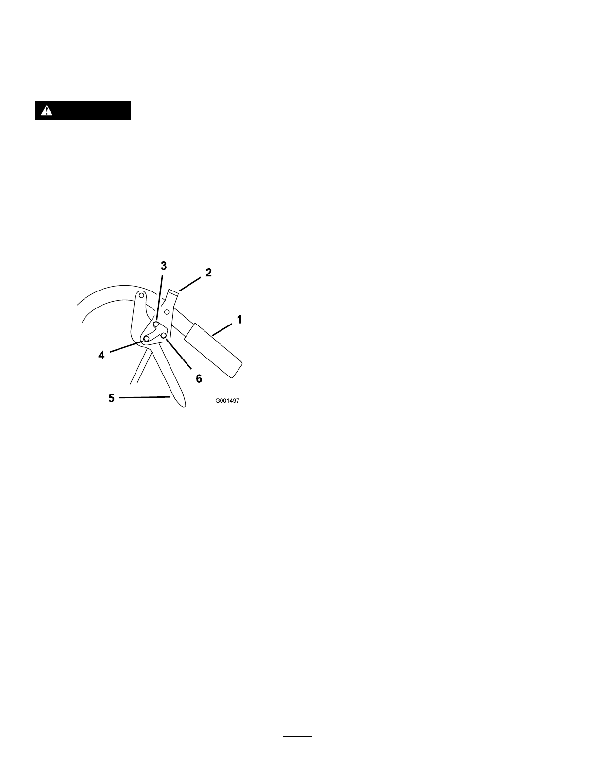
5.TurntheignitionkeytotheRunposition(Figure
8).
6.T ostartacoldengine,movethethrottlecontrol
midwaybetweentheFastandSlowpositions.
7.T ostartawarmengine,movethethrottlecontrol
totheFastposition.
8.Pullthechokeknobiftheengineiscold(Figure
8).
Note:Awarmorhotengineusuallydoesnot
requireanychoking.
g001497
9.Grasptherecoil-starthandlermlyandpullitout
untilpositiveengagementresults;thenpullthe
handlevigorouslytostarttheengine.
Note:Allowtheropetorecoilslowly.
Important:Donotpulltherecoilropetoits
limitorreleasethestarterhandlewhenyou
pullouttheropebecausetheropemaybreak
ortherecoilassemblymaybedamaged.
10.PushthechoketotheOffpositionastheengine
warmsup.
11.Iftheengineiscold,allowittowarmupandthen
movethethrottlecontroltotheFastposition.
StoppingtheEngine
Important:Inanemergency,youcanstopthe
engineimmediatelybyturningtheignitionkeyto
theOffposition.
1.Movethethrottlelevertotheslowposition
(Figure8).
Note:Iftheenginehasbeenworkinghardor
ishot,letitidleforaminutebeforestoppingit
tohelpcoolit.
2.TurntheignitionkeytotheOffposition.
14
Page 15
3.Settheparkingbrakesandremovethekey.
4.Disconnectthewirefromthesparkplugto
preventsomeonefromaccidentallystartingthe
machinewhiletransportingorstoringit.
5.Closethefuel-shutoffvalvebeforetransporting
orstoringthemachine.
Important:Closethefuel-shutoffvalve
beforetransportingorthestoringthe
machine,topreventfuelleakage.
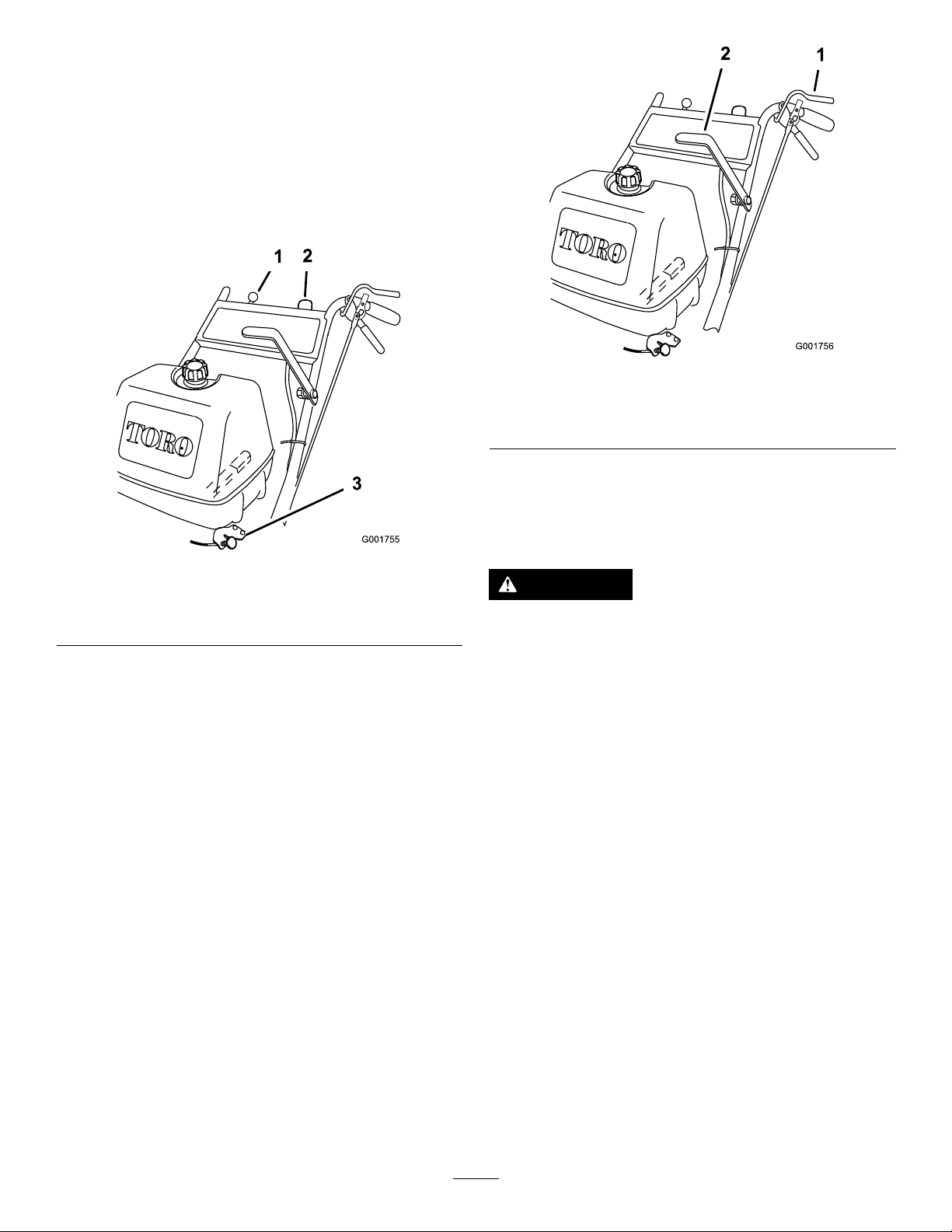
g001756
Figure9
Figure8
1.Throttlecontrol
2.Ignitionswitch
3.Choke
Operatingthe Blade-Control(PTO)Lever
Theblade-control(PTO)leverengagesand
disengagesthepowertothemowerblades.
EngagingtheMowerBlades(PTO)
1.Squeezetheoperatorpresencecontrol(OPC)
leversagainstthehandles(Figure9).
2.Pushtheblade-control(PTO)leverrmly
forwarduntilitlatchesoverthecenter(Figure9).
3.Starttheengineandrepeattheprocedure
toengagethemowerbladesiftheoperator
presencecontrol(OPC)leversarereleased.
DisengagingtheMowerBlades
(PTO)
Todisengagetheblades,pulltheblade-controllever
rearwardalltheway(Figure9).Theenginewill
stopwhentheOPCleversarereleasedwiththe
blade-controlleverengaged.
1.OperatorPresence
Control(OPC)lever
2.Powertake-offlever(PTO)
TheSafety-Interlock System
g001755
CAUTION
Ifsafety-interlockswitchesaredisconnected
ordamagedthemachinecouldoperate
unexpectedly,causingpersonalinjury.
•Donottamperwiththeinterlockswitches.
•Checktheoperationoftheinterlock
switchesdaily,andreplaceanydamaged
switchesbeforeoperatingthemachine.
Understandingthe
Safety-InterlockSystem
Thesafety-interlocksystemisdesignedtopreventthe
enginefromstartingunless:
•Theblade-control(PTO)leverisdisengaged.
•ThemachineisshiftedintotheNeutralposition.
•TheignitionkeyisintheRunposition.
Thesafety-interlocksystemisdesignedtostop
theenginewhen:
•Theoperator-presence-control(OPC)leversare
releasedwhenthetransmissionorthebladesare
engaged.
•TheignitionkeyisturnedtotheOffposition.
15
Page 16

•Themachineisshiftedintogearwithoutholding
theOPClevers.
•Theblade-control(PTO)leverisengagedwithout
holdingtheOPClevers.
TestingtheSafety-Interlock
System
DrivingForwardor Backward
Thethrottlecontrolregulatestheenginespeedas
measuredinrpm(revolutionsperminute).Move
thethrottlecontrolintotheFastpositionforthebest
mowingperformance.
Testthesafety-interlocksystembeforeyouusethe
machineeachtime.Ifthesafetysystemdoesnot
operateasdescribed,haveanAuthorizedService
Dealerrepairthesafetysystemimmediately.
1.Settheparkingbrakes,movetheshiftleverinto
theNeutralposition,disengagetheblade-control
(PTO)leverandplacethethrottleforward.
2.Starttheengine;refertoStartingtheEngine
(page14).
3.Withoutholdingtheoperator-presence-control
(OPC)levers,engagetheblade-control(PTO)
lever.
Note:Theengineshouldstop.
4.Disengagetheblade-control(PTO)lever.
5.Withtheenginerunning,holddowntheOPC
leversandengagetheblade-control(PTO)lever.
Note:Themowerbeltshouldengageandthe
mowerbladesshouldbeginrotating.
6.ReleasetheOPClevers.
Note:Theengineshouldstop.
7.Withtheenginerunning,movetheshiftlever
intogearandreleasetheOPClevers.
DrivingForward
1.Ensurethattheparkingbrakesareengaged.
2.SqueezetheOPCleversagainstthehandles.
3.Movetheshiftleverintoaforwardgear.
4.Releasetheparkingbrakes;refertoReleasing
theParkingBrakes(page14).
5.Slowlyreleasethedrivelevers.
Note:T ogostraight,releasethedrivelevers
equally.T oturn,squeezethedriveleveronthe
samesideasthedirectionyouwanttoturn.
DrivingBackward
1.Ensurethattheparkingbrakesareengaged.
2.SqueezetheOPCleversagainstthehandles.
3.Movetheshiftleverintothereversegear.
4.Releasetheparkingbrakes;refertoReleasing
theParkingBrakes(page14).
5.Slowlyreleasethedrivelevers.
Note:Youmustpullthemowerbackwardto
assistitsrearwardmovement.
Note:Theengineshouldstop.
8.Withtheenginerunning,turntheignitionkey
totheOffposition.
Note:Theengineshouldstop.
9.Ifalltheaboveconditionsarenotmet,have
anAuthorizedServiceDealerrepairthesafety
systemimmediately.
StoppingtheMower
1.Squeezethedriveleversallthewaybackto
engagethebrakes.
2.Settheparkingbrakes.RefertoSettingthe
ParkingBrakes(page14).
3.ShifttransmissionintotheNeutralposition.
4.MovethethrottletotheStopposition,andwait
forallmovingpartstostopbeforeleavingthe
operatingposition.
CAUTION
Childrenorbystandersmaybeinjured
iftheymoveorattempttooperatethe
machinewhileitisunattended.
Alwaysremovetheignitionkeyand
settheparkingbrakewhenleavingthe
machineunattended,evenifjustfora
fewminutes.
16
Page 17

TransportingtheMachine
Adjustingthe
Useaheavy-dutytrailerortrucktotransportthe
machine.Ensurethatthetrailerortruckhasall
necessarylightingandmarkingasrequiredbylaw.
Pleasecarefullyreadallthesafetyinstructions.
Knowingthisinformationcouldhelpyou,yourfamily,
pets,orbystandersavoidinjury.
Totransportthemachine:
1.Stoptheengine,removethekey,setthebrake,
andclosethefuelvalve.
2.Securelyfastenthemachinetothetraileror
truckwithstraps,chains,cable,orropes.
3.Secureatrailertotowingvehiclewithsafety
chains.
4.Ifapplicable,connectthetrailerbrakes.
SideDischargingor MulchingtheGrass
Thismowerhasahingedgrassdeectorthat
dispersesclippingstothesideanddowntowardthe
turf.
Wheel-Drive-BeltTension
Youmayneedtoincreasethewheel-drive-belttension
undercertainoperatingconditions,suchasmowing
overhillyterrainorwhilepullingasulky.
1.Stoptheengine,removethekey ,andwaitforall
movingpartstostop.
2.Disconnectthewiresfromthesparkplugs.
3.Disengagetheneutral/parkingbrakelocks,and
releasethedriveleverstoreducethespring
force.
4.Removethedrivespringfromtheadjustment
bolt(Figure10).
DANGER
Withoutthegrassdeector,dischargecover,
orcompletegrasscatcherassemblymounted
inplace,youandothersareexposedtoblade
contactandthrowndebris.Contactwith
rotatingmowerblade(s)andthrowndebris
willcauseinjuryordeath.
•Neverremovethegrassdeectorfrom
themower,becausethegrassdeector
routesmaterialdowntowardtheturf.Ifthe
grassdeectoriseverdamaged,replaceit
immediately.
•Neverputyourhandsorfeetunderthe
mower.
•Nevertrytocleardischargeareaormower
bladesunlessyoureleasetheOPClevers
andthepowertake-off(PTO)isoff.Rotate
theignitionkeytotheOffposition.Also
removethekeyandpullthewireoffthe
sparkplug(s).
Figure10
1.PositionA4.Drivespring
2.PositionB
3.PositionC
5.Removethelocknutthatsecurestheadjustment
bolttothedrive-pulleyshield(Figure10).
6.Locateboltassemblyinthedesiredtension
positionasfollows:
5.Adjustmentbolt(inposition
A)
6.Drive-pulleyshield
•PositionAfornormalconditions
•PositionBformoresevereconditions
•PositionCforthemostsevereconditions
Note:Thewheeldrivetensionislowest
whentheboltassemblyisinPositionA.
ThetensionincreasesinPositionsBandC
(Figure10).
g001498
7.Installtheadjustmentboltandthedrivespring.
8.Repeatstepsthroughfortheoppositeside.
17
Page 18

AdjustingtheHeightofCut
Thismachinehasa26to108mm(1to4-1/4inch)
rangefortheheightofcut.Thiscanbeachievedby
adjustingbladespacers,rearaxleheight,andfront
casterspacers.UsetheHeight-of-CutChart(page
22)toselectthecombinationofadjustmentsrequired.
AdjustingtheBladeHeight
4.Slidetheboltdownthroughthespindle,and
changethespacersasneeded(Figure11).
5.Installtheboltandcurvedwasher,addextra
spacer(s),andsecurethemwithathinwasher
andanut(Figure11).
6.T orquethebladeboltto101to108N-m(75to
80ft-lb).
Adjustthebladesbyusingthe4spacers(6mm)
(1/4inch)onthebladespindlebolts.Thisallowsfora
25mm(1inch)adjustmentrange,in6mm(1/4inch)
increments,ofcuttingheightinanyaxleposition.Use
thesamenumberofbladespacersonallbladesto
achievealevelcut(2aboveand2below,1above
and3below,etc.).
1.Disengagetheblade-control(PTO)leverand
settheparkingbrakes.
2.Stoptheengineandwaitforallmovingpartsto
stopbeforeleavingtheoperatingposition.
3.Holdthebladeboltandremovethenut(Figure
11).
AdjustingtheAxleHeight
Adjusttheaxlepositiontotheselectedheight-of-cut
setting.RefertotheHeight-of-CutChart(page22).
1.Disengagetheblade-control(PTO)leverand
settheparkingbrakes.
2.Stoptheengineandwaitforallmovingpartsto
stopbeforeleavingtheoperatingposition.
3.Loosen,butdonotremove,the2axlepivotbolts
andthe2axleadjustmentbolts(Figure12).
g001455
Figure12
Figure11
1.Blade
2.Bladebolt5.Thinwasher
3.Curvedwasher
1.Axlepivotbolt2.Axleadjustmentbolt
4.Placeajackundertherearcenteroftheengine
frame.Raisethebackendoftheengineframe
upenoughtoremovethefront2axleadjustment
bolts(Figure12).
Note:Usejackstandstosupportthemachine.
5.Raiseorlowertheengineframewiththejackso
thatyoucaninstallthefront2axleadjustment
boltsinthedesiredholelocation(Figure12).
Note:Useataperedpunchtohelpalignthe
holes.
6.Tightenall4boltsandlowerthemower.
7.Adjustthecontrolrodsandthebrakelinkages
asrequired.RefertoAdjustingtheControlRods
g001454
(page38)andAdjustingtheBrakes(page32).
Important:Youmustadjustthecontrolrods
4.Spacer
6.Nut
andthebrakelinkagewhenyouchangethe
axlepositionsforpropertractionandbrake
function.
18
Page 19

AdjustingtheCasterPosition
g012676
1 2
G012677
1.UsingtheHeight-of-CutChart(page22),adjust
thecasterspacerstomatchwiththeaxlehole
selected(Figure13).
g012676
Figure14
Figure13
1.Latchpin
2.Spacer,5mm(3/16inch)
3.Spacer,13mm(1/2inch)
2.Removethelatchpin,slidethecasterfromthe
support,andchangethespacers(Figure13).
3.Installthecasterinthesupportandinsertthe
latchpin(Figure13).
AdjustingtheFlowBafe
Youcanadjustthemowerdischargeowfordifferent
typesofmowingconditions.Positionthecamlock
andbafetogivethebestqualityofcut.
1.DisengagethePTOandsettheparkingbrake.
2.Stoptheengine,removethekey,andwait
forallmovingpartstostopbeforeleavingthe
operatingposition.
1.Slot
g001456
2.Nut
PositioningtheFlowBafe
Thefollowingguresareonlyrecommendationsfor
use.Adjustmentswillvarybygrasstype,moisture
content,andheightofgrass.
Note:Iftheenginepowerdrawsdownandthe
mowergroundspeedisthesame,openupthebafe.
PositionA
Thisisthefull-rearposition(seeFigure15).The
suggesteduseforthispositionisafollows:
•Useforshort,lightgrassmowingconditions.
•Useindryconditions.
•Useforsmallergrassclippings.
•Usetopropelgrassclippingsfartherawayfrom
themower.
3.Loosenthenut(Figure14).
4.Adjustthebafeandnutintheslottothedesired
dischargeow,andtightenthenut.
g012677
Figure15
19
Page 20

PositionB
G012678
G012679
g012931
AdjustingtheHandle
Usethispositionwhenbagging(Figure16).
Figure16
PositionC
Thisisthefullopenposition.Thesuggestedusefor
thispositionisasfollows(Figure17):
•Useintall,densegrassmowingconditions.
•Useinwetconditions.
•Usetolowertheenginepowerconsumption.
•Useatanincreasedgroundspeedinheavy
conditions.
Height
Youcanadjustthehandlepositiontomatchyour
heightpreference.
1.Removethehairpincotterpinsandclevispins
fromthedriveleversandneutrallocks(Figure
18).
g012678
g012931
Figure18
1.Controlrod
2.Clevispin
3.OperatorPresence
Controllever(OPC)
4.Handle
5.Neutrallock
6.Hairpincotterpin
7.Drivelever
Figure17
2.Loosentheupperbolts(3/8x1-1/4inches)and
angenutsecuringhandletorearframe(Figure
19).
3.Removethelowerbolts(3/8x1inch)andange
nutssecuringthehandletotherearframe
(Figure19).
4.Pivotthehandletothedesiredoperatingposition
andinstallthelowerangebolts(3/8x1inch)
andangenutsintothemountingholes.
Note:Tightenallangebolts.
g012679
20
Page 21

Figure19
1.Upperhandle6.Lowermountingholes
2.Rearframe
3.Flangebolt(3/8x1inch)
4.Locknut(3/8inch)
5.Uppermountinghole
7.Lowposition
8.Middleposition
9.Highposition
5.Adjustthecontrolrodlengthbyrotatingthe
controlrodintherodtting(Figure18).
6.Installahairpincotterbetweenthedrivelevers
andtheneutrallocksandintotheclevispins
(Figure18).
Note:Makesurethattheclevispinsare
insertedintotheneutrallocks.
7.Checktheparkingbrakeadjustment.Refer
toCheckingtheBrakesinBrakeMaintenance
(page32).
g001493
21
Page 22

Height-of-CutChart
Numberofspacersbelow
Axle
position
A00
A01
A10
B01
B10
B11
B20
C
C
C
C
D21
D30
D31
D40
E31
E40
E41
thecaster
13mm
(1/2inch)
11
20
21
30
Numberof1/4inchbladespacersbelowthespindle
5mm
(3/16inch)
43210
26mm
(1inch)
29mm
(1-1/8inch)
35mm
(1-3/8inch)
35mm
(1-3/8inch)
41mm
(1-5/8inch)
45mm
(1-3/4inch)
51mm
(2inch)
48mm
(1-7/8inch)
55mm
(2-1/8inch)
57mm
(2-1/4inch)
64mm
(2-1/2inch)
61mm
(2-3/8inch)
64mm
(2-1/2inch)
70mm
(2-3/4inch)
76mm
(3inch)
73mm
(2-7/8inch)
79mm
(3-1/8inch)
82mm
(3-1/4inch)
32mm
(1-1/4inch)
35mm
(1-3/8inch)
41mm
(1-5/8inch)
41mm
(1-5/8inch)
48mm
(1-7/8inch)
51mm
(2inch)
57mm
(2-1/4inch)
54mm
(2-1/8inch)
60mm
(2-3/8inch)
64mm
(2-1/2inch)
70mm
(2-3/4inch)
67mm
(2-5/8inch)
70mm
(2-3/4inch)
76mm
(3inch)
82mm
(3-1/4inch)
79mm
(3-1/8inch)
86mm
(3-3/8inch)
89mm
(3-1/2inch)
38mm
(1-1/2inch)
41mm
(1-5/8inch)
48mm
(1-7/8inch)
48mm
(1-7/8inch)
54mm
(2-1/8inch)
57mm
(2-1/4inch)
64mm
(2-1/2inch)
60mm
(2-3/8inch)
67mm
(2-5/8inch)
70mm
(2-3/4inch)
76mm
(3inch)
73mm
(2-7/8inch)
76mm
(3inch)
82mm
(3-1/4inch)
89mm
(3-1/2inch)
86mm
(3-3/8inch)
92mm
(3-5/8inch)
95mm
(3-3/4inch)
45mm
(1-3/4inch)
48mm
(1-7/8inch)
54mm
(2-1/8inch)
54mm
(2-1/8inch)
60mm
(2-3/8inch)
64mm
(2-1/2inch)
70mm
(2-3/4inch)
67mm
(2-5/8inch)
73mm
(2-7/8inch)
76mm
(3inch)
83mm
(3-1/4inch)
79mm
(3-1/8inch)
82mm
(3-1/4inch)
89mm
(3-1/2inch)
95mm
(3-3/4inch)
92mm
(3-5/8inch)
98mm
(3-7/8inch)
102mm
(4inch)
51mm
(2inch)
54mm
(2-1/8inch)
60mm
(2-3/8inch)
60mm
(2-3/8inch)
67mm
(2-5/8inch)
70mm
(2-3/4inch)
76mm
(3inch)
73mm
(2-7/8inch)
79mm
(3-1/8inch)
83mm
(3-1/4inch)
89mm
(3-1/2inch)
86mm
(3-3/8inch)
89mm
(3-1/2inch)
95mm
(3-3/4inch)
102mm
(4inch)
98mm
(3-7/8inch)
105mm
(4-1/8inch)
108mm
(4-1/4inch)
22
Page 23

Maintenance
Note:Determinetheleftandrightsidesofthemachinefromthenormaloperatingposition.
RecommendedMaintenanceSchedule(s)
MaintenanceService
Interval
Aftertherst8hours
Aftertherst25hours
Beforeeachuseordaily
Every25hours
Every50hours
Every100hours
MaintenanceProcedure
•Changetheengineoil.
•Checkthemowerbelttension.
•Checkthemowerbelttension.
•Checkthesafetysystem.
•Greasethecasterwheelsandcasterpivot.
•Checktheengine-oillevel.
•Cleantheair-intakescreen.
•Cleantheairintakescreenfromgrassanddebrisbeforeeachuse.
•Checkthebrakes.
•Inspecttheblades.
•Cleanthemowerdeck.
•Cleanthefoamair-cleanerelement.
•Greasethemower-beltidler.
•Checkthepaperair-cleanerelement.
•Checkthetirepressure.
•Checkthebelts.
•Checkthemowerbelttension.
•Changetheengineoil.
•Checkthesparkplugs.
•Checkandcleantheengine-coolingnsandshrouds.
•Replacethepaperair-cleanerelement.
Every200hours
Every250hours
Every400hours
Beforestorage
•Changetheoillter .
•Replacethefuellter.
•Replacethefuel-ventlter.
•Greasethetransmissioncouplers(moreoftenindirtyordustyconditions).
•Greasethewheelbearings(moreoftenindirtyordustyconditions).
•Paintchippedsurfaces.
•Performallmaintenanceprocedureslistedabovebeforestorage.
Important:Refertoyourengineowner’smanualforadditionalmaintenanceprocedures.
CAUTION
Ifyouleavethekeyintheignitionswitch,someonecouldaccidentlystarttheengineand
seriouslyinjureyouorotherbystanders.
Removethekeyfromtheignitionanddisconnectthespark-plugwire(s)fromthesparkplug(s)
beforeyoudoanymaintenance.Setthewireasidesothatitdoesnotaccidentallycontact
thesparkplug.
23
Page 24

Lubrication
GreaseType:#2general-purposelithium-basedor
molybdenum-basedgrease
LubricatingtheMachine
1.DisengagethePTOandsettheparkingbrake.
2.Stoptheengine,removethekey,andwait
forallmovingpartstostopbeforeleavingthe
operatingposition.
3.Cleanthegreasettingswitharag.Makesure
toscrapeanypaintoffthefrontofthetting(s).
4.Connectagreaseguntothetting.Pump
greaseintothettingsuntilgreasebeginsto
oozeoutofthebearings.
5.Wipeupanyexcessgrease.
LubricatingtheCasterand WheelBearings
g001458
Figure21
GreasingtheMower-Belt Idler
Greasethettingonthemower-belt-idler-armpivot
(Figure22).
Note:Removethemower-deckcovertoaccessthe
greasettingforthemower-belt-idlerarm.
1.Lubricatethefront-wheelbearingsandfront
spindles(Figure20).
2.Lubricatethedrive-wheelbearings.
Figure20
GreasingtheTransmission Couplers
g001459
Figure22
g001457
32-inchand36-inchmowerdeck
Lubricatethetransmissioncouplersandidlerarm
pivotslocatedinthebackofthemachine(Figure21).
g001781
Figure23
48-inchmowerdeck
24
Page 25

EngineMaintenance
CleaningtheFoamAir-Cleaner
Element
ServicingtheAirCleaner
ServiceInterval:Every25hours—Cleanthefoam
air-cleanerelement.
Every50hours—Checkthepaperair-cleaner
element.
Every200hours—Replacethepaperair-cleaner
element.
Note:Servicetheaircleanermorefrequently(every
fewoperatinghours)iftheoperatingconditionsare
extremelydustyorsandy.
Important:Donotoilthefoamorpaperelement.
RemovingtheFoamandPaper
Elements
1.DisengagethePTOandsettheparkingbrake.
2.Stoptheengine,removethekey,andwait
forallmovingpartstostopbeforeleavingthe
operatingposition.
3.Cleanaroundtheaircleanertopreventdirtfrom
gettingintotheengineandcausingdamage
(Figure24).
4.Unscrewthecoverknobsandremovethe
air-cleanercover(Figure24).
5.Unscrewthehoseclampandremovetheair
cleanerassembly(Figure24).
6.Carefullypullthefoamelementoffthepaper
element(Figure24).
1.Washthefoamelementinliquidsoapand
warmwater.Whentheelementisclean,rinse
itthoroughly.
2.Drytheelementbysqueezingitinacleancloth.
Important:Replacethefoamelementifit
istornorworn.
ServicingthePaperAir-Cleaner
Element
1.Donotcleanthepaperlter,replaceit(Figure
24).
2.Inspecttheelementfortears,anoilylm,or
damagetotherubberseal.
3.Replacethepaperelementifitisdamaged.
InstallingtheFoamandPaper
Elements
Important:Topreventenginedamage,always
operatetheenginewiththecompletefoamand
paperaircleanerassemblyinstalled.
1.Carefullyslidethefoamelementontothepaper
air-cleanerelement(Figure24).
2.Placetheaircleanerassemblyontotheair
cleanerbaseandsecureitwiththe2wingnuts
(Figure24).
3.Placetheair-cleanercoverintopositionand
tightenthecoverknob(Figure24).
Figure24
1.Cover
2.Hoseclamp4.Foamelement
3.Paperelement
ServicingtheEngineOil
ServiceInterval:Beforeeachuseordaily—Check
theengine-oillevel.
Aftertherst8hours—Changetheengineoil.
Every100hours—Changetheengineoil.
Every200hours—Changetheoillter.
Note:Changetheoilmorefrequentlywhenthe
operatingconditionsareextremelydustyorsandy .
OilType:Detergentoil(APIserviceSF,SG,SH,SJ
orSL)
g012619
CrankcaseCapacity:1.7L(1.8USqt)withthelter
removed;1.5L(1.6USqt)withoutthelterremoved
Viscosity:Refertothetable(Figure25).
25
Page 26

ChangingtheEngineOil
1.Parkthemachinesothatthedrainsideisslightly
lowerthantheoppositesidetoensurethatthe
oildrainscompletely.
2.DisengagethePTOandsettheparkingbrake.
3.Stoptheengine,removethekey,andwait
forallmovingpartstostopbeforeleavingthe
operatingposition.
4.Slidethedrainhoseovertheoildrainvalve.
5.Placeapanbelowthedrainhose.
Figure25
CheckingtheEngine-OilLevel
1.Parkthemachineonalevelsurface.
2.DisengagethePTOandsettheparkingbrake.
3.Stoptheengine,removethekey,andwait
forallmovingpartstostopbeforeleavingthe
operatingposition.
4.Cleanaroundtheoildipstick(Figure26)sothat
dirtcannotfallintothellerholeanddamage
theengine.
g004216
Note:Rotateoildrainvalvetoallowoiltodrain
(Figure27).
6.Whenoilhasdrainedcompletely,closethedrain
valve.
7.Removethedrainhose(Figure27).
Note:Disposeoftheusedoilatarecycling
center.
Figure26
1.Oildipstick
2.Fillertube
5.Unscrewtheoildipstickandwipetheendclean
(Figure26).
6.Slidetheoildipstickfullyintothellertube,but
donotthreaditontothetube(Figure26).
7.Pullthedipstickoutandlookattheend.Ifthe
oillevelislow,slowlypouronlyenoughoilinto
thellertubetoraisetheleveltotheFullmark.
Important:Donotoverllthecrankcase
withoilandruntheengine;enginedamage
canresult.
g001464
g001466
Figure27
1.Oildrainvalve2.Oildrainhose
8.Slowlypourapproximately80%ofthespecied
oilintothellertube(Figure26).
9.Checktheoillevel;refertoCheckingthe
Engine-OilLevel(page13)
10.Slowlyaddtheadditionaloiltobringittothe
Fullmark.
26
Page 27

ChangingtheOilFilter
1
ServicingtheSparkPlugs
Note:Changetheoilltermorefrequentlywhenthe
operatingconditionsareextremelydustyorsandy .
1.Draintheoilfromtheengine;refertoChanging
theEngineOil(page26).
2.Removetheoldlter(Figure28).
Figure28
1.Oillter
3.Applyathincoatofnewoiltotherubbergasket
onthereplacementlter(Figure28).
2.Adapter
ServiceInterval:Every100hours—Checkthespark
plugs.
Ensurethattheairgapbetweenthecenterelectrode
andthesideelectrodeiscorrectbeforeinstallingeach
sparkplug.Useaspark-plugwrenchforremoving
andinstallingthesparkplugsandagappingtoolora
feelergaugetocheckandadjusttheairgap.Install
newsparkplugsifnecessary.
Type:Champion®RCJ8Yorequivalent
AirGap:0.75mm(0.030inch)
RemovingtheSparkPlugs
1.DisengagethePTOandsettheparkingbrake.
2.Stoptheengine,removethekey,andwait
g001465
forallmovingpartstostopbeforeleavingthe
operatingposition.
3.Disconnectthewiresfromthesparkplugs
(Figure29).
4.Installthereplacementoilltertothelter
adapter,turntheoillterclockwiseuntilthe
rubbergasketcontactsthelteradapter,then
tightenthelteranadditional3/4turn(Figure
28).
5.Fillthecrankcasewiththepropertypeofnew
oil;refertoServicingtheEngineOil(page25).
6.Runtheengineforabout3minutes,stopthe
engine,andcheckforoilleaksaroundtheoil
lteranddrainvalve.
7.Checktheengineoillevelandaddoilifneeded.
8.Wipeupanyspilledoil.
g001469
Figure29
1.Spark-plugwire/sparkplug
4.Cleanaroundthesparkplugstopreventdirt
fromfallingintotheengineandpotentially
causingdamage.
5.Removethesparkplugsandthemetalwashers.
CheckingtheSparkPlugs
1.Lookatthecenterofthesparkplugs(Figure30).
Note:Ifyouseelightbrownorgrayonthe
insulator,theengineisoperatingproperly .A
blackcoatingontheinsulatorusuallymeans
thattheaircleanerisdirty.
2.Ifneeded,cleanthesparkplugwithawirebrush
toremovecarbondeposits.
27
Page 28

Figure30
1.Centerelectrode;insulator3.Airgap(nottoscale)
2.Sideelectrode
Important:Alwaysreplacethesparkplugs
whentheyhavewornelectrodes,anoilylm,
oracrackedinsulator.
3.Checkthegapbetweenthecenterelectrode
andthesideelectrode(Figure30).
Note:Bendthesideelectrode(Figure30)ifthe
gapisnotcorrect.
InstallingtheSparkPlugs
1.Installthesparkplugsandthemetalwasher.
Ensurethattheairgapissetcorrectly.
2.Tightenthesparkplugsto22N-m(16ft-lb).
3.Connectthewirestothesparkplugs(Figure30).
FuelSystem
Maintenance
ServicingtheFuelSystem
DANGER
Incertainconditions,gasolineisextremely
g001470
ammableandhighlyexplosive.Areor
explosionfromgasolinecanburnyouand
othersandcandamageproperty.
•Draingasolinefromthefueltankwhenthe
engineiscold.Dothisoutdoorsinanopen
area.Wipeupanygasolinethatspills.
•Neversmokewhendraininggasoline,and
stayawayfromanopenameorwherea
sparkmayignitethegasolinefumes.
DrainingtheFuelTank
1.Parkthemachineonalevelsurfacetoensure
thatthefueltankdrainscompletely;then
disengagethepowertake-off(PTO),setthe
parkingbrake,andturntheignitionkeytothe
Offposition.Removethekey.
2.Closethefuel-shutoffvalveatthefueltank
(Figure31).
3.Squeezetheendsofthehoseclamptogether
andslideitupthefuellineawayfromfuellter
(Figure31).
4.Pullthefuellineoffthefuellter(Figure31).
Note:Openthefuel-shutoffvalveandallowthe
gasolinetodrainintoafuelcontaineroradrain
pan.
Note:Nowisthebesttimetoinstallanewfuel
lterbecausethefueltankisempty .Referto
ReplacingtheFuelFilter(page29).
5.Installthefuellineontothefuellter.Slidethe
hoseclampclosetothevalvetosecurethefuel
line.
28
Page 29

Figure31
g001467
1.Fuel-shutoffvalve2.Clamp
ReplacingtheFuelFilter
ServiceInterval:Every200hours/Yearly(whichever
comesrst)
Neverinstalladirtylterifitisremovedfromthefuel
line.
Note:Notehowthefuellterisinstalledinorderto
installthenewltercorrectly.
Note:Wipeupanyspilledfuel.
1.DisengagethePTOandsettheparkingbrake.
2.Stoptheengine,removethekey,andwait
forallmovingpartstostopbeforeleavingthe
operatingposition.
3.Closethefuel-shutoffvalveatthefueltank
(Figure31).
4.Squeezetheendsofthehoseclampstogether
andslidethemawayfromthelter(Figure32).
g001468
Figure32
1.Hoseclamp3.Filter
2.Fuelline
5.Removethelterfromthefuellines.
6.Installanewlterandmovethehoseclamps
closetothelter.
7.Openthefuel-shutoffvalveatthefueltank
(Figure31).
8.Checkforfuelleaks,andrepairifneeded.
9.Wipeupanyfuelthatspilled.
29
Page 30

ServicingtheFuel-VentSystem
g014686
1 2
ServiceInterval:Every200hours/Yearly(whichever
comesrst)
1.DisengagethePTOandsettheparkingbrake.
2.Stoptheengine,removethekey,andwait
forallmovingpartstostopbeforeleavingthe
operatingposition.
3.Removetheexistingfuel-ventlter(Figure33).
4.Installanewlter.
DriveSystem
Maintenance
CheckingtheTirePressure
ServiceInterval:Every50hours/Monthly(whichever
comesrst)
Maintaintheairpressureinthereartiresat83to97
kPa(12to14psi).Uneventirepressurecancause
anunevencut.
Note:Thefronttiresaresemi-pneumatictiresanddo
notrequireairpressuremaintenance.
Figure33
1.Fuel-ventlter2.Rightsideoftheengine
g001055
g014686
Figure34
30
Page 31

CoolingSystem
Maintenance
CleaningtheAir-intake Screen
Beforeeachuse,removeanybuildupofgrass,dirt,
orotherdebrisfromthecylinderandcylinder-head
coolingns,theair-intakescreenontheywheelend,
andthecarburetor-governorleversandlinkage.This
willhelpensureadequatecoolingandcorrectengine
speedandwillreducethepossibilityofoverheating
andmechanicaldamagetotheengine.
CleaningtheCooling System
ServiceInterval:Beforeeachuseordaily
Every100hours/Yearly(whichevercomesrst)
1.DisengagethePTOandsettheparkingbrake.
2.Stoptheengine,removethekey,andwait
forallmovingpartstostopbeforeleavingthe
operatingposition.
3.Removetheair-intakescreen,therecoilstarter,
andthefanhousing(Figure35).
4.Cleanthedebrisandgrassfromtheengine
parts.
5.Installtheair-intakescreen,therecoilstarter,
andthefanhousing(Figure35).
g001472
Figure35
1.Air-intakescreen4.Bolt
2.Fanhousing5.Nut
3.Recoilstarter
31
Page 32

BrakeMaintenance
ServicingtheBrakes
Beforeeachuse,checkthebrakesonbothalevel
surfaceandaslope.
Alwayssettheparkingbrakewhenyoustopthe
machineorleaveitunattended.Iftheparkingbrake
doesnotholdthemachinesecurely,adjustit.
CheckingtheBrakes
1.Parkthemachineonalevelsurface,disengage
theblade-control(PTO)lever.
2.Stoptheengine,removethekey,andwait
forallmovingpartstostopbeforeleavingthe
operatingposition.
3.Applytheparkingbrakes.
Note:Thewheelsmustlockwhenyoutryto
pushthemachineforward.
4.Ifthewheelsdonotlock,adjustthebrakes;refer
toAdjustingtheBrakes(page32).
5.Releasethebrakesandmovetheneutral/brake
lockstotheNeutralposition.
Note:Thewheelsshouldrotatefreely;ifthey
donot,refertoAdjustingtheBrakes(page32).
AdjustingtheBrakes
Iftheparkingbrakesdonotholdsecurely,adjustthem.
1.Checkthebrakesbeforeyouadjustthem;refer
toCheckingtheBrakes(page32).
g001561
Figure36
1.Brakerod2.Wingnut
4.Positionthewingnutssothatthebrakesengage
whenyousqueezethedriveleversenoughto
placetheneutral/parkingbrakelocksforward,
andthensetthebrakes.
5.Checktheoperationofthebrakesagain;referto
CheckingtheBrakes(page32).
Important:Whenyoureleasetheparking
brakes,therearwheelsshouldrotatefreely
whenyoupushthemower.Iftheydo
not,contactanAuthorizedServiceDealer
immediately.
6.Checkthecontrolrodlength,refertoAdjusting
theBrakes(page32).
2.Releasetheparkingbrakes;refertoReleasing
theParkingBrakes(page14).
3.T oadjustthebrakes,rotatethewingnutsonthe
brakerods(Figure36).
Note:Rotatethewingnutsclockwisetotighten
thebrakes;rotatethemcounterclockwiseto
loosenthem.
32
Page 33

BeltMaintenance
CheckingtheBelts
ServiceInterval:Every50hours/Monthly(whichever
comesrst)—Checkthebelts.
Checkthebeltsforcracks,frayededges,burnmarks,
wear,signsofoverheating,oranyotherdamage.
Replaceanydamagedbelts.
ReplacingtheTraction DriveBelt
1.Removethehairpincottersecuringthebrake
rodtothebrakearmtorelaxthetensiononthe
beltidler(Figure37).
2.Removethebottomboltandloosenthetopbolt
oftheshieldtorotateitforbeltclearance(Figure
37).
3.Liftthebeltpasttheidlerandoffthedrivepulley
(Figure37).
4.Raisethewheeloffthegroundenoughto
removethebelt.
5.Replacethetraction-drivebelt.
6.Securetheshieldwiththepreviouslyremoved
bolt,andtightenthebolts(Figure37).
7.Securethebrakerodtothebrakearmwiththe
hairpincotter(Figure37).
3.Raisetherearofthemachineandholditupwith
jackstands.
4.Removethemowerbelt(Figure38).
Figure38
1.Idlerpulleyinslot4.Beltguide
2.Tractionbelt
3.Mowerbelt6.Mowerbelt
5.Loosenthepivotboltenoughtoslidetheidler
pulleyintheslot,andremovethetractionbelt
fromtheengineandthedrivepulleys(Figure
38).
6.Installthenewdrivebeltaroundtheengineand
thedrivepulleys(Figure38).
7.Slidetheidlerpulleyintheengineframeto
tensionthetractionbelt(Figure38).
8.Installthemowerbelt(Figure38).
5.19mm(3/4inch)
g001475
Figure37
1.Drivebelt3.Tire
2.Drivespring4.Adjustmentbolt
ReplacingtheDriveBelt
1.Disengagetheblade-control(PTO)leverand
settheparkingbrakes.
2.Stoptheengineandwaitforallmovingpartsto
stopbeforeleavingtheoperatingposition.
9.Checkthebeltguideundertheengineframefor
theproperadjustment(Figure38).
Note:Thedistancebetweenthebeltguideand
mowerbeltshouldbe19mm(3/4inch)when
youengagethemowerbelt.Adjustthebeltif
necessary.Thedisengagedbeltshouldnotdrag
orfalloffthepulleywhentheguidesareproperly
adjusted.
g001562
ReplacingtheMowerBelt
Important:Thebrakeneedstobeadjustedwhen
thebelttensionorthebrakelinkageisadjusted.
1.Disengagetheblade-control(PTO)leverand
settheparkingbrakes.
2.Stoptheengineandwaitforallmovingpartsto
stopbeforeleavingtheoperatingposition.
3.Removetheknobsandthebeltcoveronthe
mower.
4.Removetheidlerpulleyandthewornbelt.
5.Installthenewmowerbelt.
33
Page 34

6.Installtheidlerpulley.
7.Engagetheblade-control(PTO)leverandcheck
thebelttension.RefertoCheckingtheBelts
(page33).
Note:Thepropermowerbelttensionis44to
67N-m(10to15ft-lb)withthebeltdeected
13mm(1/2inch)halfwaybetweenthepulleys
(Figure42orFigure43).
8.Engagetheblade-control(PTO)lever.
9.Checktheclearancebetweenthebellcrankand
thetransmissionoutputshaft(Figure39).
g001478
Figure40
32-inchand36-inchmowerdeck
Figure39
1.2to3mm(1/16to1/8inch)
2.Bellcrank
3.Transmissionoutputshaft6.Clevis
4.Hairpincotter
5.Clevispin
Note:Theclearanceshouldbe2to3mm(1/16
to1/8inch).
10.Removethehairpincotterpinandtheclevispin
fromthebellcrank.
11.Rotatetheclevisclockwiseontherodtoincrease
theclearance;rotateitcounterclockwiseto
decreaseit(Figure39).
12.Disengagetheblade-control(PTO)lever.
Note:Iftheassistarmdoesnotcontactthe
frontstoponthemowerdeck(Figure40or
Figure41),adjusttheclevistobringthebell
crankclosertothetransmissionoutputshaft
(Figure39).
1.13mm(1/2inch)deection
here
2.Assistarm5.Turnbuckle
3.Frontstop
g001477
48-inchmowerdeck
1.13mm(1/2inch)deection
here
2.Assistarm5.Turnbuckle
3.Frontstop
4.Locknut
g001566
Figure41
4.Locknut
13.Checkthebeltguideundertheengineframefor
theproperadjustment(Figure38).
Note:Thedistancebetweenthebeltguideand
themowerbeltshouldbe32mm(1-1/4inch)
whenyouengagethemowerbelt.Adjustthe
34
Page 35

mowerbeltasnecessary.Thedisengagedbelt
shouldnotdragorfalloffthepulleywhenthe
guidesareproperlyadjusted.
AdjustingtheMowerBelt Tension
AdjustingtheTensionfor32-inch
and36-inchMowerDecks
ServiceInterval:Aftertherst8hours—Checkthe
mowerbelttension.
Aftertherst25hours—Checkthemowerbelt
tension.
Every50hours—Checkthemowerbelttension.
Important:Adjustthebrakewheneveryouadjust
thebelttensionorthebrakelinkage.
Important:Thebeltmustbetightenoughto
notslipduringheavyloadswhilecuttinggrass.
Over-tensioningthebeltwillreducethelifeofthe
spindlebearing,thebelt,andtheidlerpulley.
Thebeltmustbetightenoughsothatitdoesnot
slipduringheavyloadswhilecuttinggrass,and
over-tensioningwillreducebeltandspindlebearing
life.
1.Disengagetheblade-control(PTO)leverand
settheparkingbrakes.
2.Stoptheengineandwaitforallmovingpartsto
stopbeforeleavingtheoperatingposition.
3.Loosenthelocknutontheturnbuckle(Figure
42).
4.Rotatetheturnbuckletowardtherearofthe
mowertoincreasethetensiononthebelt.
Rotatetheturnbuckletowardthefrontofthe
mowertodecreasethetensiononthebelt
(Figure42).
Figure42
32-inchand36-inchmowerdeck
1.Mowerbeltwith13mm
(1/2inch)deection
6.Tightenthelocknutontheturnbuckle.
7.Checktheadjustmentofthebladebrake;refer
toAdjustingtheBladeBrake(page41).
2.Idlerpulley
AdjustingtheTensionfor48-inch
MowerDecks
Important:Thebeltmustbetightenoughto
notslipduringheavyloadswhilecuttinggrass.
Over-tensioningthebeltwillreducethespindle
bearinglife,thebeltlifeandtheidlerpulleylife.
Important:Thebrakeneedstobeadjustedwhen
thebelttensionorthebrakelinkageisadjusted.
1.Disengagetheblade-control(PTO)leverand
settheparkingbrakes.
2.Stoptheengineandwaitforallmovingpartsto
stopbeforeleavingtheoperatingposition.
g001476
Note:Theeyeboltthreadsonbothendsofthe
turnbuckleshouldbeengagedaminimumof8
mm(5/16inch).
5.Engagetheblade-controllever(PTO)andcheck
thebelttension.Adjustthetensionuntilitis
correct.
Note:Thepropermowerbelttensionis44to
67N-m(10to15ft-lb)withthebeltdeected
13mm(1/2inch)halfwaybetweenthepulleys
(Figure42).
3.Loosenthelocknutontheturnbuckle(Figure
44).
4.Adjustthetensionofthebelt.
•Rotatetheturnbuckletowardtherearofthe
mowertoincreasethetensiononthebelt.
•Rotatetheturnbuckletowardthefrontofthe
mowertodecreasethetensiononthebelt
(Figure44).
Note:Thepropermowerbelttensionis44to
67N-m(10to15ft-lb)withthebeltdeected
13mm(1/2inch)halfwaybetweenthepulleys
(Figure43).
35
Page 36

Figure43
48-inchmowerdeck
1.Idlerpulley2.Mowerbeltwith13mm
(1/2inch)deection
Note:Theeyeboltthreadsonbothendsofthe
turnbuckleshouldbeengagedaminimumof8
mm(5/16inch).
6.Ifthereisnoadjustmentleftintheturnbuckle
andthebeltisstillloose,therearidlerpulley
needstobepositionedtothemiddleorfront
hole(Figure45).Usetheholethatwillgivethe
correctadjustment.
7.Whenyoumovetheidlerpulley,youmustmove
thebeltguide.Movethebeltguidetothefront
position(Figure45).
g001565
r:\g001848
Figure45
1.Rearidlerpulley4.Beltguideinbackposition
2.Middlehole5.Frontidlerpulley
3.Fronthole
8.Checkthebeltguideundertheengineframefor
properadjustment(Figure46).
Figure44
1.13mm(1/2inch)deection
here
2.Assistarm5.Turnbuckle
3.Frontstop
4.Locknut
5.Engagetheblade-controllever(PTO)andcheck
thebelttension.
Note:Thedistancebetweenthebeltguideand
themowerbeltshouldbe19mm(3/4inch)when
youengagethemowerbelt(Figure46).Adjust
themowerbeltasnecessary.Thedisengaged
beltshouldnotdragorfalloffthepulleywhenthe
guidesandbelttensionareproperlyadjusted.
9.Checktheadjustmentofthebladebrake;refer
toAdjustingtheBladeBrake(page41).
r:\g001566
36
Page 37

Figure46
1.Idlerpulleyinslot4.Beltguide
2.Tractionbelt
3.Mowerbelt6.Mowerbelt
5.19mm(3/4inch)
AdjustingthePTO-Engagement
Linkage
TheadjustmentforthePTO-engagementlinkage
islocatedbeneaththefrontleft-handcornerofthe
enginedeck.
1.Disengagetheblade-control(PTO)leverand
settheparkingbrakes.
2.Stoptheengineandwaitforallmovingpartsto
stopbeforeleavingtheoperatingposition.
3.Engagetheblade-controllever(PTO).
4.Adjustthelinkagelengthtowherethelower
endofthebellcrankjustclearstheaxlesupport
gusset(Figure47).
g001475
g001847
Figure47
1.Bellcrank4.Yoke
2.Safetyswitchlocated
underenginedeck
3.Bellcrankjustclearsthe
gussetwiththePTO
engaged
5.Nut
6.Assistarmlink
5.Makesurethattheassistarmisagainstthe
rear-assist-armstoponthedeck(Figure48).
6.Pushtheblade-controllever(PTO)downtothe
disengagedposition.
7.Theassistarmshouldcontactthe
front-assist-armstoponthedeck.Ifit
doesnotcontact,adjustthebellcranksothatit
isclosertothegusset(Figure48).
Figure48
1.Yoke5.Assistarmlink
2.Nut6.Assistarm
3.Rearassistarmstop7.Turnbuckle
4.Frontassistarmstop
37
g001849
Page 38

8.T oadjusttheassistarmlink,removethehairpin
g012931
cotterpinfromtheassistarm(Figure48).
ControlsSystem
9.Loosenthenutagainsttheyoke(Figure47).
10.Removetheassistarmlinkfromtheassistarm
androtatethelinktoadjustthelength.
11.Installtheassistarmlinkintotheassistarmand
secureitwiththehairpincotterpin(Figure48).
12.Checkiftheassistarmhitsagainstthestops
correctly.
AdjustingthePTOSafetySwitch
1.Disengagetheblade-control(PTO)leverand
settheparkingbrakes.
2.Stoptheengineandwaitforallmovingpartsto
stopbeforeleavingtheoperatingposition.
3.Disengagetheblade-controllever(PTO).
Makesurethattheassistarmisagainstthe
front-assist-armstop.
4.Ifneeded,adjusttheblade-safetyswitchby
looseningtheboltsholdingtheswitchbracket
(Figure49).
5.Movethemountingbracketuntilthebellcrank
pressestheplungerby6mm(1/4inch).
Note:Makesurethatthebellcrankdoesnot
touchtheswitchbody;otherwise,damagetothe
switchcouldoccur(Figure49).
Maintenance
AdjustingtheControlRods
1.Removethehairpincotterpinsandclevispins
fromthedriveleversandneutrallocks(Figure
50).
Figure50
1.Controlrod
2.Clevispin
3.Operator-presence-control
lever(OPC)
4.Handle8.Drivelever
5.Neutrallock
6.Hairpincotter
7.Lefthandleshown
g012931
Figure49
1.Bellcrank
2.Boltsandnuts
6.Tightentheswitchmountingbracket.
2.Adjustthecontrolrodlengthbythreadingthe
rodinoroutoftherodttinguntilthereisa5to6
mm(3/16to1/4inches)clearancebetweenthe
controlrodandthebottomoftheneutral/parking
brakelock(Figure51).
g001855
3.Switchmountingbracket
4.Switchbody
38
Page 39

Figure51
1.Handle4.Drivelever
2.Neutral/parkingbrakelock
3.5to6mm(3/16to1/4
inch)clearance
5.Forwardspeed
6.Controlrod
MowerDeck Maintenance
ServicingtheCutting Blades
Toensureasuperiorqualityofcut,keeptheblades
sharp.Forconvenientsharpeningandreplacement,
youmaywanttokeepextrabladesonhand.
g001495
WARNING
Awornordamagedbladecanbreak,anda
pieceofthebladecouldbethrownintothe
operator'sorbystander'sarea,resultingin
seriouspersonalinjuryordeath.
3.Installthecontrolrodtothedriveleverandthe
neutral/parkingbrakelock.Securethecontrol
rodwithaclevispinandahairpincotter(Figure
51).
4.Checktheoperationofthecontrolrod.
Note:Ifyouneedtoadjustit,removethe
hairpincotterandtheclevispinthatsecurethe
controlrodtothedrivelevers.
5.Adjustthecontrolrodlengthbyrepeatingthe
previoussteps.
•Inspectthebladeperiodicallyforwearor
damage.
•Replaceawornordamagedblade.
PreparingtoInspectorService
theBlades
1.Parkthemachineonalevelsurface,disengage
theblade-controllever,andsettheparking
brake.
2.TurntheignitionkeytotheOffposition.
3.Removethekeyanddisconnectthespark-plug
wire(s)fromthesparkplug(s).
39
Page 40

InspectingtheBlades
ServiceInterval:Beforeeachuseordaily
1.Inspectthecuttingedges(Figure52).Ifthe
edgesarenotsharporhavenicks,removeand
sharpentheblades.RefertoSharpeningthe
Blades(page41).
g001564
Figure54
2.Measurefromalevelsurfacetothecutting
edge,positionA,oftheblades(Figure55).
Figure52
1.CuttingEdge3.Wear/slotformingin
curvedarea
2.Sail4.Crackinthecurvedarea
2.Inspecttheblades,especiallythecurvedarea
(Figure52).Ifyounoticeanydamage,wear,or
aslotforminginthisarea(item3.inFigure52),
immediatelyinstallanewblade.
CheckingforBentBlades
1.Rotatethebladesuntiltheendsfaceforward
andbackward(Figure53).
g006530
Note:Notethisdimension.
g001563
Figure55
1.Measurefromthecuttingedgetoalevelsurface
3.Rotatetheoppositeendsofthebladesforward.
4.Measurefromalevelsurfacetothecuttingedge
ofthebladesatthesamepositionasinstep1.
Note:Thedifferencebetweenthedimensions
obtainedinsteps1and2mustnotexceed3mm
(1/8inch).Ifthisdimensionexceeds3mm(1/8
inch),thebladeisbentandmustbereplaced.
RefertoRemovingtheBlades(page41)and
InstallingtheBlades(page41).
WARNING
Figure53
Abladethatisbentordamagedcould
breakapartandcouldseriouslyinjureor
killyouorbystanders.
g001481
•Alwaysreplacebentordamaged
bladewithanewblade.
•Neverleorcreatesharpnotchesin
theedgesorsurfacesofblade.
40
Page 41

RemovingtheBlades
Replacethebladesifyouhitasolidobjectorifthe
bladesareoutofbalanceorbent.T oensureoptimum
performanceandcontinuedsafetyconformanceof
themachine,usegenuineTororeplacementblades.
Replacementbladesmadebyothermanufacturers
mayresultinnon-conformancewithsafetystandards.
1.Holdthebladeboltwithawrench.
2.Removethenut,bladebolt,curvedwasher,
blade,spacers,andthinwasherfromthespindle
(Figure56).
g000276
Figure57
1.Sharpenatoriginalangle
2.Checkthebalanceofthebladebyputtingitona
bladebalancer(Figure58).
Note:Ifthebladestaysinahorizontalposition,
thebladeisbalancedandcanbeused.Ifthe
bladeisnotbalanced,lesomemetaloffthe
endofthesailareaonly(Figure58).Repeatthis
procedureuntilthebladeisbalanced.
g000277
Figure58
Figure56
1.Blade
2.Bladebolt5.Thinwasher
3.Curvedwasher
4.Spacer
6.Nut
SharpeningtheBlades
1.Usealetosharpenthecuttingedgeatboth
endsoftheblade(Figure57).
Note:Maintaintheoriginalangle.Theblade
retainsitsbalanceifthesameamountof
materialisremovedfrombothcuttingedges.
1.Blade2.Balancer
InstallingtheBlades
1.Installthecurvedwasherandthentheblade
ontothebolt.Selectthepropernumberof
spacer(s)fortheheightofcut,andslidethebolt
intothespindle(Figure56).
Important:Thecurvedpartoftheblade
mustpointupwardtowardtheinsideofthe
mowertoensurepropercutting.
2.Installtheremainingspacer(s)andsecurethem
withathinwasherandanut(Fig.Figure56).
g001454
3.T orquethebladeboltto101to108N-m(75to
80ft-lb).
AdjustingtheBladeBrake
1.DisengagethePTO,turntheignitionkeytooff,
andremovethekey.
2.Waitforallmovingpartstostopbeforeleaving
theoperatingpositionandsettingtheparking
brake.
3.Ifnecessary,adjustthespringmountingboltsso
thattheblade-brakepadrubsagainstbothsides
ofthepulleygroove(Figure59).
4.Adjustthenutattheendoftheblade-brakerod
untilthereis3mmto5mm(1/8to3/16inch)
betweenthenutandspacer(Figure59).
41
Page 42

5.Engagetheblades.
g012749
Note:Ensurethebladebrakepadnolonger
contactsthepulleygroove.
g012749
Figure60
Figure59
1.Springmountingbolts3.3mmto5mm(1/8to
3/16inch)
2.Blade-brakepad
ReplacingtheGrass
Deector
WARNING
Anuncovereddischargeopeningcouldallow
thelawnmowertothrowobjectsatyouor
bystanders,resultinginseriousinjuryor
death.Also,contactwiththebladecould
occur.
Neveroperatethelawnmowerunlessyou
installacoverplate,amulchplate,oragrass
chuteandcatcher.
1.Bolt
2.Spacer6.GrassDeector
g001485
3.Locknut
4.Spring8.Jhookendofspring
5.Springinstalled
7.Lendofspring,place
behinddeckedgebefore
installingbolt
2.Placethespacerandthespringontothegrass
deector,andplacetheL-endofspringbehind
deckedge.
Note:MakesurethattheL-endofthespringis
installedbehinddeckedgebeforeinstallingthe
boltasshowninFigure60.
3.Installtheboltandthenut.PlacetheJ-hookend
ofthespringaroundthegrassdeector(Figure
60).
Important:Thegrassdeectormustbeable
torotate.Liftthedeectoruptothefully
openpositionandensurethatitrotatesinto
thefullydownposition.
1.Removethelocknut,bolt,springandspacer
holdingthedeectortothepivotbrackets
(Figure60).
Note:Removedamagedorworngrass
deector.
42
Page 43

Storage
CleaningandStorage
1.Disengagethepowertake-off(PTO),setthe
parkingbrake,turntheignitionkeytotheOff
position,andremovethekey.
2.Removegrassclippings,dirt,andgrimefromthe
externalpartsoftheentiremachine,especially
theengine.Cleandirtandchafffromtheoutside
oftheenginecylinder-headnsandtheblower
housing.
Important:Youcanwashthemachine
withmilddetergentandwater.Donot
pressure-washthemachine.Avoid
excessiveuseofwater,especiallynearthe
shift-leverplateandtheengine.
3.Checkthebrake;refertoCheckingtheBrakes
(page32).
4.Servicetheaircleaner;refertoServicingtheAir
Cleaner(page25).
12.Installthesparkplug(s),butdonotinstallthe
wireonthesparkplug(s).
13.Checkandtightenallbolts,nuts,andscrews.
Repairorreplaceanypartthatisdamagedor
worn.
14.Paintallscratchedorbaremetalsurfaceswith
paintavailablefromyourAuthorizedService
Dealer.
15.Storethemachineinaclean,drygarageor
storagearea.Removethekeyfromtheignition
switchandkeepitinamemorableplace.Cover
themachinetoprotectitandkeepitclean.
5.Greasethemachine;refertoLubricatingthe
Machine(page24).
6.Changethecrankcaseoil;refertoChangingthe
EngineOil(page26).
7.Checkthetirepressure;refertoCheckingthe
TirePressure(page30).
8.Forlong-termstorage:
A.Addstabilizer/conditioneradditivetofuelin
thetank.
B.Runtheenginetodistributeconditionedfuel
throughthefuelsystem(5minutes).
C.Stoptheengine,allowittocool,anddrain
thefueltank;refertoDrainingtheFuelTank
(page28),orruntheengineuntilitstops.
D.Starttheengineandrunituntilitstops.
Repeattheprocess,withthechokeon,until
theenginewillnotstart.
E.Disposeoffuelproperly.Recycleit
accordingtolocalcodes.
Note:Donotstorestabilizer/conditioned
gasolineover90days.
9.Removeandchecktheconditionofthespark
plug(s);refertoServicingtheSparkPlugs(page
27).
10.Withthesparkplug(s)removedfromthe
engine,pour2tablespoonsofengineoilintothe
spark-plughole.
11.Usethestartertocranktheengineanddistribute
theoilinsidethecylinder.
43
Page 44

Troubleshooting
Problem
Theenginewillnotstart,startshard,or
failstokeeprunning.
Theenginelosespower.
PossibleCauseCorrectiveAction
1.Thefueltankisempty.1.Fillthefueltankwithgasoline.
2.Thefuel-shutoffvalveisclosed.2.Openthefuel-shutoffvalve.
3.Thechokeisnotinthecorrectposition.
4.Theaircleanerisdirty.
5.Thespark-plugwireislooseor
disconnected.
6.Thesparkplugispittedorfouled,or
thegapisincorrect.
7.Thereisdirtinthefuellter.7.Replacethefuellter.
8.Dirt,water,orstalefuelisinthefuel
system.
1.Theengineloadisexcessive.1.Reducethegroundspeed.
2.Theaircleanerisdirty.
3.Theoillevelinthecrankcaseislow.3.Addoiltothecrankcase.
4.Thecoolingnsandairpassages
undertheengineblowerhousingare
plugged.
5.Thesparkplugispittedorfouled,or
thegapisincorrect.
6.Theventholeinthefuelcapisplugged.6.Cleanorreplacethefuelcap.
7.Thereisdirtinthefuellter.7.Replacethefuellter.
8.Dirt,water,orstalefuelisinthefuel
system.
3.Closethechokeiftheengineiscold;
openthechokeiftheengineiswarm.
4.Cleanorreplacetheair-cleaner
element.
5.Installthewireonsparkplug.
6.Installanew,correctlygappedspark
plug.
8.ContactanAuthorizedServiceDealer.
2.Cleantheair-cleanerelement.
4.Removetheobstructionfromthe
coolingnsandairpassages.
5.Installanew,correctlygappedspark
plug.
8.ContactanAuthorizedServiceDealer.
Theengineoverheats.
Themachinedoesnotdrive.
Thereisabnormalvibration.
1.Theengineloadisexcessive.1.Reducethegroundspeed.
2.Theoillevelinthecrankcaseislow.2.Addoiltothecrankcase.
3.Thecoolingnsandairpassages
undertheengineblowerhousingare
plugged.
1.Theshiftleverisinneutral.1.Movetheshiftlevertoadrivegear
2.Thetractionbeltisworn,loose,or
broken.
3.Thetractionbeltisoffapulley .3.Changethebelt.
4.Theidlerspringisbrokenormissing.4.Replacethespring.
1.One/severalcuttingbladesis/arebent
orunbalanced.
2.Ablademountingboltisloose.2.Tightentheblademountingbolt.
3.Theenginemountingboltsareloose.3.Tightentheenginemountingbolts.
4.Theenginepulley ,idlerpulley,orblade
pulleyisloose.
5.Theenginepulleyisdamaged.
6.Thebladespindleisbent.
3.Removetheobstructionfromthe
coolingnsandairpassages.
position.
2.Changethebelt.
1.Installnewcuttingblade(s).
4.Tightentheappropriatepulley.
5.ContactanAuthorizedServiceDealer.
6.ContactanAuthorizedServiceDealer.
44
Page 45

Problem
PossibleCauseCorrectiveAction
Themachineproducesanunevencutting
height.
Thebladesdonotrotate.
1.Theblade(s)is/arenotsharp.1.Sharpentheblade(s).
2.One/severalcuttingblade(s)is/are
bent.
3.Themowerisnotlevel.
4.Theundersideofthemowerisdirty.4.Cleantheundersideofthemower.
5.Thetirepressureisnotcorrect.5.Adjustthetirepressure.
6.Abladespindleisbent.
1.Themowerdeckbeltiswornorloose.
2.Themowerdeckbeltisbroken.2.Installanewdeckbelt.
3.Themowerdeckbeltisoffpulley.3.Inspectthebeltandreplaceitifitis
4.Theidlerspringisbrokenormissing.4.Replacethespring.
2.Installnewcuttingblade(s).
3.Levelthemowerfromside-to-sideand
front-to-rear.
6.ContactanAuthorizedServiceDealer.
1.Checkthebelttension.
damaged.Checkthepulleysandidlers
andadjustthebelttension.
45
Page 46

Schematics
g001639
ElectricalSchematic(Rev .A)
46
Page 47

Notes:
Page 48

TheToroT otalCoverageWarranty
ALimitedWarranty(seewarrantyperiodsbelow)Contractor
Landscape
Equipment
(LCE)
ConditionsandProductsCovered
TheToroCompanyanditsafliate,ToroWarrantyCompany,pursuanttoanagreement
betweenthem,jointlypromisetotheoriginalpurchasertorepairtheToroProducts
listedbelowifdefectiveinmaterialsorworkmanship.
Thefollowingtimeperiodsapplyfromthedateofpurchasebytheoriginalowner:
ProductsWarrantyPeriod
21in.Mowers2yearsResidentialUse
1yearCommercialUse
4
•Engines
Honda–2years
Kawasaki–3years
30in.Mowers2yearsResidentialUse
1yearCommercialUse
4
•Engines
Mid-SizeWalk-BehindMowers
4
•Engines
GrandStand
4
•Engines
•Frame
®
ZMaster
•Engines
2000SeriesMowers
4
•Frame
®
ZMaster
•Engines
•Frame
ZMaster
•Engines
®
3000SeriesMowers
4
5000SeriesMowers
4
®
Mowers
Kawasaki–3years
2years
Kawasaki–3years
5yearsor1,200hours
3years
Lifetime(originalowneronly)
4yearsor500hours
3years
Lifetime(originalowneronly)
5yearsor1,200hours
3years
Lifetime(originalowneronly)
5yearsor1,200hours
KohlerCommand–2years
KohlerEFI–3years
•Frame
®
ZMaster
•Engines
6000SeriesMowers
4
•Frame
®
ZMaster
•Engines
7000SeriesMowers
4
•Frame
®
ZMaster
•Engines
8000SeriesMowers
4
•Frame
Lifetime(originalowneronly)
5yearsor1,200hours
Kawasaki–3years
Lifetime(originalowneronly)
5yearsor1,200hours
2years
Lifetime(originalowneronly)
2yearsor1,200hours
2years
Lifetime(originalowneronly)
AllMowers
•Battery90daysPartsandLabor
1yearPartsonly
•BeltsandTires90days
•Attachments1year
1
Residentialusemeansuseoftheproductonthesamelotasyourhome.Useatmorethanone
locationisconsideredcommercialuseandthecommercialwarrantywouldapply.
2
Whicheveroccursrst.
3
LifetimeFrameW arranty-Ifthemainframe,consistingofthepartsweldedtogethertoformthe
tractorstructurethatothercomponentssuchastheenginearesecuredto,cracksorbreaksin
normaluse,itwillberepairedorreplaced,atToro'soption,underwarrantyatnocostforpartsand
labor.Framefailureduetomisuseorabuseandfailureorrepairrequiredduetorustorcorrosion
arenotcovered.
4
SomeenginesusedonT oroProductsarewarrantedbytheenginemanufacturer.
1
1
2
3
2
3
2
3
2
3
2
3
2
3
2
3
InstructionsforObtainingWarrantyService
IfyouthinkthatyourToroProductcontainsadefectinmaterialsorworkmanship,
followthisprocedure:
1.ContactanyAuthorizedT oroServiceDealertoarrangeserviceattheir
dealership.T olocateadealerconvenienttoyou,refertotheY ellowPagesof
yourtelephonedirectory(lookunder“LawnMowers”)oraccessourwebsite
atwww.Toro.com.Y oumayalsocallthenumberslistedinitem#3tousethe
24-hourT oroDealerlocatorsystem.
2.Bringtheproductandyourproofofpurchase(salesreceipt)totheService
Dealer.Thedealerwilldiagnosetheproblemanddetermineifitiscovered
underwarranty.
3.IfforanyreasonyouaredissatisedwiththeServiceDealer’sanalysisorwith
theassistanceprovided,contactusat:
RLCCustomerCareDepartment
ToroWarrantyCompany
811 1LyndaleAvenueSouth
Bloomington,MN55420-1 196
888-865-5676(U.S.Customers)
888-865-5691(Canadacustomers)
OwnerResponsibilities
YoumustmaintainyourToroProductbyfollowingthemaintenanceprocedures
describedintheOperator'sManual.Suchroutinemaintenance,whetherperformedby
adealerorbyyou,isatyourexpense.
ItemsandConditionsNotCovered
Thereisnootherexpresswarrantyexceptforspecialemissionsystemcoverage
andenginewarrantycoverageonsomeproducts.Thisexpresswarrantydoesnot
coverthefollowing:
•Costofregularmaintenanceserviceorparts,suchaslters,fuel,lubricants,oil
changes,sparkplugs,airltersbladesharpeningorwornblades,cable/linkage
adjustments,orbrakeandclutchadjustments
•Componentsfailingduetonormalwear
•Anyproductorpartwhichhasbeenalteredormisusedorneglectedandrequires
replacementorrepairduetoaccidentsorlackofpropermaintenance
•Pickupanddeliverycharges
•RepairsorattemptedrepairsbyanyoneotherthananAuthorizedT oroService
Dealer
•Repairsnecessaryduetofailuretofollowrecommendedfuelprocedure(consult
Operator'sManualformoredetails)
–Removingcontaminantsfromthefuelsystemisnotcovered
–Useofoldfuel(morethanonemonthold)orfuelwhichcontainsmorethan
10%ethanolormorethat15%MTBE
–Failuretodrainthefuelsystempriortoanyperiodofnon-useoverone
month
GeneralConditions
AllrepairscoveredbythesewarrantiesmustbeperformedbyanAuthorizedToro
ServiceDealerusingT oroapprovedreplacementparts.
NeitherTheToroCompanynorT oroWarrantyCompanyisliableforindirect,
incidentalorconsequentialdamagesinconnectionwiththeuseoftheToro
Productscoveredbythiswarranty,includinganycostorexpenseofproviding
substituteequipmentorserviceduringreasonableperiodsofmalfunctionor
non-usependingcompletionofrepairsunderthiswarranty .
Allimpliedwarrantiesofmerchantability(thattheproductistforordinaryuse)
andtnessforuse(thattheproductistforaparticularpurpose)arelimitedto
thedurationoftheexpresswarranty .
Somestatesdonotallowexclusionsofincidentalorconsequentialdamages,
orlimitationsonhowlonganimpliedwarrantylasts,sotheaboveexclusions
andlimitationsmaynotapplytoyou.
Thiswarrantygivesyouspeciclegalrights,andyoumayalsohaveotherrights
whichvaryfromstatetostate.
CountriesOtherthantheUnitedStatesorCanada
CustomerswhohavepurchasedT oroproductsoutsidetheUnitedStatesorCanadashouldcontacttheirT oroDistributor(Dealer)toobtainguaranteepoliciesforyourcountry,
province,orstate.IfforanyreasonyouaredissatisedwithyourDistributor'sserviceorhavedifcultyobtainingguaranteeinformation,contacttheT oroimporter.Ifallother
remediesfail,youmaycontactusatToroWarrantyCompany.
AustralianConsumerLaw:AustraliancustomerswillnddetailsrelatingtotheAustralianConsumerLaweitherinsidetheboxoratyourlocalToroDealer.
374-0252RevG
 Loading...