

Page 1

FormNo.3360-525RevA
Groundsmaster
®
328-D
2&4WheelDriveTractionUnits
ModelNo.30626—SerialNo.280000201andUp
ModelNo.30627—SerialNo.280000201andUp
ModelNo.30630—SerialNo.280000201andUp
ModelNo.30631—SerialNo.280000201andUp
Registeratwww.T oro.com.OriginalInstructions(EN)
Page 2
Warning
CALIFORNIA
Proposition65Warning
Theengineexhaustfromthisproduct
containschemicalsknowntotheStateof
Californiatocausecancer,birthdefects,
orotherreproductiveharm.
Important:Theengineinthisproductisnot
equippedwithasparkarrestermufer.Itisa
violationofCaliforniaPublicResourceCode
Section4442touseoroperatethisengineonany
forest-covered,brush-covered,orgrass-covered
landasdenedinCPRC4126.Otherstatesor
federalareasmayhavesimilarlaws.
Thismanualidentiespotentialhazardsandhas
safetymessagesidentiedbythesafetyalertsymbol
(Figure2),whichsignalsahazardthatmaycauseserious
injuryordeathifyoudonotfollowtherecommended
precautions.
Figure2
1.Safetyalertsymbol
Thismanualuses2otherwordstohighlightinformation.
Importantcallsattentiontospecialmechanical
informationandNoteemphasizesgeneralinformation
worthyofspecialattention.
Introduction
Readthisinformationcarefullytolearnhowtooperate
andmaintainyourproductproperlyandtoavoidinjury
andproductdamage.Youareresponsibleforoperating
theproductproperlyandsafely.
YoumaycontactTorodirectlyatwww.Toro.comfor
productandaccessoryinformation,helpndinga
dealer,ortoregisteryourproduct.
Wheneveryouneedservice,genuineToroparts,or
additionalinformation,contactanAuthorizedService
DealerorToroCustomerServiceandhavethemodel
andserialnumbersofyourproductready .Figure1
identiesthelocationofthemodelandserialnumbers
ontheproduct.Writethenumbersinthespace
provided.
Figure1
1.Modelandserialnumberlocation
ModelNo.
SerialNo.
Contents
Introduction.................................................................2
Safety...........................................................................4
SafeOperatingPractices.......................................4
ToroRidingMowerSafety....................................6
SoundPower........................................................7
SoundPressure.....................................................7
Vibration..............................................................7
SafetyandInstructionalDecals.............................8
Setup..........................................................................14
1InstallingtheSteeringCylinder(Models
30627&30631only).......................................14
2InstallingtheTieRod(Models30627&
30631only)....................................................15
3InstallingtheRearBumper(Models30627
&30631only).................................................15
4InstallingtheFrontandRearWheels.................16
5RemovingtheBatteryfromtheChassis.............16
6InstallingtheSeat.............................................16
7InstallingtheSeatBelt......................................18
8InstallingtheRollBar.......................................19
9PushingtheTractionUnitOffofthe
Pallet..............................................................19
10ActivatingandChargingtheBattery................19
11InstallingtheBatteryintheChassis.................20
12InstallingtheBallJointandConnectingthe
LiftCylinder...................................................21
13InstallingtheRearWeight...............................22
14FinishingtheSetup........................................23
ProductOverview......................................................24
Controls.............................................................24
Specications.....................................................26
Attachments/Accessories...................................26
Operation...................................................................27
©2008—TheToro®Company
8111LyndaleAvenueSouth
Bloomington,MN55420
Contactusatwww.Toro.com.
2
PrintedintheUSA.
AllRightsReserved
Page 3

BeforeOperating................................................27
Starting/StoppingEngine...................................30
BleedingFuelSystem..........................................31
CheckingtheInterlockSwitches.........................31
PushingorTowingtheTractionUnit...................32
OperatingCharacteristics...................................32
Maintenance...............................................................34
RecommendedMaintenanceSchedule(s)................34
DailyMaintenanceChecklist...............................35
Lubrication.............................................................36
EngineMaintenance...............................................37
GeneralAirCleanerMaintenance.......................37
ServicingAirCleaner..........................................37
CleaningtheRadiatorandScreen........................38
ChangingEngineOilAndFilter..........................38
BleedingAirFromInjectors...............................39
FuelSystemMaintenance.......................................39
FuelTank...........................................................39
FuelLinesandConnections................................39
ServicingtheWaterSeparator.............................39
ElectricalSystemMaintenance................................40
Fuses..................................................................40
ServicingtheBattery...........................................40
DriveSystemMaintenance.....................................41
AdjustingRearWheelToe–in(Models30626
&30630only).................................................41
AdjustingSteeringStops(Models30627&
30631only)....................................................41
AdjustingtheRearWheelBearings(Models
30626&30630only).......................................41
ChangingRearAxleLubricant(Models30627
&30631only).................................................42
CheckingSteeringCylinderBoltTorque
(Models30627&30631only).........................42
ChangingBidirectionalClutchLubricant
(Models30627&30631only).........................42
CoolingSystemMaintenance..................................43
CleaningRadiatorAndScreen............................43
ChangingCoolantInCoolingSystem..................43
BrakeMaintenance.................................................44
AdjustingtheBrakes...........................................44
BeltMaintenance....................................................45
ServicingtheEngineBelts..................................45
AdjustingPTODriveBeltTension.....................46
ControlsSystemMaintenance.................................46
AdjustingThrottle..............................................46
AdjustingTractionControlRod..........................46
AdjustingTractionPedalFrictionWheel.............47
AdjustingtheTractionDriveforNeutral.............47
AdjustingtheTractionInterlockSwitch..............48
ReplacingthePTOSwitch..................................48
AdjustingtheParkingBrakeInterlock
Switch............................................................48
AdjustingtheTiltSteeringControl......................49
HydraulicSystemMaintenance...............................49
ReplacingtheHydraulicFluidFilter....................49
ChangingtheHydraulicSystemFluid..................50
Storage.......................................................................51
TractionUnit......................................................51
Engine...............................................................51
Schematics.................................................................53
3
Page 4

Safety
responsiblefortrainingtheusers.Suchinstruction
shouldemphasize:
Models30630and30631meetorexceedCEN
standardEN836:1997,ISOstandard5395:1990,and
ANSIB71.4-2004specicationsineffectatthetime
ofproduction,whenweightsareinstalledaccording
tochartintheSetupsection.
Models30626and30627meetorexceedtheB71.4
2004specicationsoftheAmericanNational
StandardsInstitute,ineffectattimeofproduction,
whenweightsareinstalledaccordingtochartin
theSetupsection.
Note:Theadditionofattachmentsmadeby
othermanufacturersthatdonotmeetAmerican
NationalStandardsInstitutecerticationwillcause
noncomplianceofthismachine.
Improperuseormaintenancebytheoperatoror
ownercanresultininjury.Toreducethepotential
forinjury,complywiththesesafetyinstructions
andalwayspayattentiontothesafetyalert
symbol,whichmeansCAUTION,WARNING,
orDANGER—“personalsafetyinstruction.”
Failuretocomplywiththeinstructionmayresultin
personalinjuryordeath.
–theneedforcareandconcentrationwhen
workingwithride-onmachines;
–controlofaride-onmachineslidingonaslope
willnotberegainedbytheapplicationofthe
brake.Themainreasonsforlossofcontrolare:
◊insufcientwheelgrip;
◊beingdriventoofast;
◊inadequatebraking;
◊thetypeofmachineisunsuitableforitstask;
◊lackofawarenessoftheeffectofground
conditions,especiallyslopes;
◊incorrecthitchingandloaddistribution.
•Theowner/usercanpreventandisresponsiblefor
accidentsorinjuriesoccurringtohimselforherself,
otherpeople,orproperty.
Preparation
•Whilemowing,alwayswearsubstantialfootwear,
longtrousers,hardhat,safetyglasses,andhearing
protection.Longhair,looseclothing,orjewelrymay
gettangledinmovingparts.Donotoperatethe
equipmentwhenbarefootorwearingopensandals.
SafeOperatingPractices
ThefollowinginstructionsarefromtheCENstandard
EN836:1997,ISOstandard5395:1990,andANSI
B71.4-2004.
Training
•ReadtheOperator’ sManualandothertrainingmaterial
carefully.Iftheoperatorormechaniccannot
readthelanguageofthismanualitistheowner’s
responsibilitytoexplainthismaterialtothem.
•Befamiliarwiththecontrols,safetysigns,andthe
properuseoftheequipment.
•Neverallowchildrenorpeopleunfamiliarwiththese
instructionstouseorservicethemower.Local
regulationsmayrestricttheageoftheoperator.
•Nevermowwhilepeople,especiallychildren,orpets
arenearby .
•Keepinmindthattheoperatororuserisresponsible
foraccidentsorhazardsoccurringtootherpeopleor
theirproperty.
•Donotcarrypassengers.
•Thoroughlyinspecttheareawheretheequipment
istobeusedandremoveallobjectswhichmaybe
thrownbythemachine.
•Warning-Fuelishighlyammable.Takethe
followingprecautions:
–Storefuelincontainersspecicallydesignedfor
thispurpose.
–Refueloutdoorsonlyanddonotsmokewhile
refueling.
–Addfuelbeforestartingtheengine.Never
removethecapofthefueltankoraddfuelwhile
theengineisrunningorwhentheengineishot.
–Iffuelisspilled,donotattempttostartthe
enginebutmovethemachineawayfromthe
areaofspillageandavoidcreatinganysourceof
ignitionuntilfuelvaporshavedissipated.
–Replaceallfueltanksandcontainercapssecurely.
•Replacefaultysilencers/mufers.
•Evaluatetheterraintodeterminewhataccessories
andattachmentsareneededtoproperlyand
safelyperformthejob.Onlyuseaccessoriesand
attachmentsapprovedbythemanufacturer.
•Alloperatorsandmechanicsshouldseekandobtain
professionalandpracticalinstruction.Theowneris
•Checktheoperatorpresencecontrols,safety
switchesandshieldstomakesuretheyareattached
4
Page 5

andfunctioningproperly .Donotoperateunless
theyarefunctioningproperly.
Adequaterearweightisnecessarytoprevent
therearwheelsfromleavingtheground.Do
notstopsuddenlywhiledeckorimplementis
raised.Donottraveldownhillwiththedeckor
implementraised.Iftherearwheelleavesthe
ground,steeringislost.
•Neveroperatethemachinewithdamagedguards,
shields,orwithoutsafetyprotectivedevicesinplace.
Besureallinterlocksareattached,adjustedproperly ,
andfunctioningproperly .
•Donotchangetheenginegovernorsettingsorover
speedtheengine.Operatingtheengineatexcessive
speedmayincreasethehazardofpersonalinjury.
•Beforeleavingtheoperator’sposition:
–stoponlevelground;
–disengagethepowertake-offandlowerthe
attachments;
Operation
•Donotoperatetheengineinaconnedspacewhere
dangerouscarbonmonoxidefumescancollect.
Engineexhaustcontainscarbonmonoxide,
whichisanodorless,deadlypoisonthatcan
killyou.
Donotrunengineindoorsorinanenclosed
area.
•Mowonlyindaylightoringoodarticiallight.
•Beforeattemptingtostarttheengine,disengageall
bladeattachmentclutches,shiftintoneutral,and
engagetheparkingbrake.
•Donotputhandsorfeetnearorunderrotatingparts.
Keepclearofthedischargeopeningatalltimes.
•Rememberthereisnosuchthingasasafeslope.
Travelongrassslopesrequiresparticularcare.To
guardagainstoverturning:
–donotstoporstartsuddenlywhengoingupor
downhill;
–machinespeedsshouldbekeptlowonslopes
andduringtightturns;
–stayalertforhumpsandhollowsandother
hiddenhazards;
–nevermowacrossthefaceoftheslope.
•Stayalertforholesintheterrainandotherhidden
hazards.
•Watchoutfortrafcwhencrossingornearroadways.
•Stopthebladesrotatingbeforecrossingsurfaces
otherthangrass.
•Neverdirectthedischargeofmaterialtoward
bystandersnorallowanyonenearthemachinewhile
inoperation.
–Settheparkingbrake;
–stoptheengineandremovethekey.
•Disengagedrivetoattachmentswhentransporting
ornotinuse.
•Stoptheengineanddisengagedrivetoattachment
–beforerefuelling;
–beforeremovingthegrasscatcher/catchers;
–beforemakingheightadjustmentunless
adjustmentcanbemadefromtheoperator’s
position.
–beforeclearingblockages;
–beforechecking,cleaningorworkingonthe
mower;
–afterstrikingaforeignobjectorifanabnormal
vibrationoccurs.Inspectthemowerfordamage
andmakerepairsbeforerestartingandoperating
theequipment.
•Keephandsandfeetawayfromthemowerdeck.
•Lookbehindanddownbeforebackinguptobesure
ofaclearpath.
•Slowdownandusecautionwhenmakingturnsand
crossingroadsandsidewalks.Disengagebladesif
notmowing.
•Beawareofthemowerdischargedirectionanddo
notpointitatanyone.
•Donotoperatethemowerundertheinuenceof
alcoholordrugs
•Usecarewhenloadingorunloadingthemachine
intoatrailerortruck
•Usecarewhenapproachingblindcorners,shrubs,
trees,orotherobjectsthatmayobscurevision.
MaintenanceandStorage
•Keepallnuts,boltsandscrewstighttobesurethe
equipmentisinsafeworkingcondition.
5
Page 6

•Neverstoretheequipmentwithfuelinthetank
insideabuildingwherefumesmayreachanopen
ameorspark.
Thisproductiscapableofamputatinghandsand
feetandthrowingobjects.Alwaysfollowallsafety
instructionstoavoidseriousinjuryordeath.
•Allowtheenginetocoolbeforestoringinany
enclosure.
•Toreducetherehazard,keeptheengine,
silencer/mufer,batterycompartmentandfuel
storageareafreeofgrass,leaves,orexcessivegrease.
•Keepallpartsingoodworkingconditionandall
hardwareandhydraulicttingstightened.Replaceall
wornordamagedpartsanddecals
•Ifthefueltankhastobedrained,dothisoutdoors.
•Becarefulduringadjustmentofthemachineto
prevententrapmentofthengersbetweenmoving
bladesandxedpartsofthemachine.
•Onmulti-spindlemowers,takecareasrotatingone
bladecancauseotherbladestorotate.
•Disengagedrives,lowerthedeck,setparkingbrake,
stopengineandremovethekeyfromtheignition.
Waitforallmovementtostopbeforeadjusting,
cleaningorrepairing.
•Cleangrassanddebrisfromdecks,drives,
silencers/mufers,engineandundersideofmachine
tohelppreventres.Cleanupoilorfuelspillage.
Useofthisproductforpurposesotherthanitsintended
usecouldprovedangeroustouserandbystanders.
•Knowhowtostoptheenginequickly.
•Donotoperatethemachinewhilewearingtennis
shoesorsneakers.
•Wearingsafetyshoesandlongpantsisadvisableand
requiredbysomelocalordinancesandinsurance
regulations.
•Handlefuelcarefully.Wipeupanyspills.
•Checkthesafetyinterlockswitchesdailyforproper
operation.Ifaswitchshouldfail,replacetheswitch
beforeoperatingthemachine.
•Beforestartingtheengine,sitontheseat.
•Usingthemachinedemandsattention.Toprevent
lossofcontrol:
–Donotdriveclosetosandtraps,ditches,creeks,
orotherhazards.
–Reducespeedwhenmakingsharpturns.Avoid
suddenstopsandstarts.
•Usejackstandstosupportcomponentswhen
required.
•Carefullyreleasepressurefromcomponentswith
storedenergy.
•Disconnectbatterybeforemakinganyrepairs.
Disconnectthenegativeterminalrstandthe
positivelast.Reconnectpositiverstandnegative
last.
•Usecarewhencheckingtheblades.Weargloves
andusecautionwhenservicingthem.Onlyreplace
blades.Neverstraightenorweldthem.
•Keephandsandfeetawayfrommovingparts.If
possible,donotmakeadjustmentswiththeengine
running.
•Chargebatteriesinanopenwellventilatedarea,
awayfromsparkandames.Unplugchargerbefore
connectingordisconnectingfrombattery.W ear
protectiveclothinganduseinsulatedtools.
ToroRidingMowerSafety
–Thismachineisnotdesignedorequippedfor
on-roaduseandisa“slow-movingvehicle.”
Ifyoumustcrossortravelonapublicroad,
youshouldbeawareofandcomplywithlocal
regulations,suchasrequiredlights,slowmoving
vehiclesigns,andreectors.
–Whennearorcrossingroads,alwaysyieldthe
right-of-way.
–Applytheservicebrakeswhengoingdownhillto
keepforwardspeedslowandtomaintaincontrol
ofthemachine.
•Raisethedeckwhendrivingfromoneworkareato
another.
•Donottouchtheengine,silencer/mufer,or
exhaustpipewhiletheengineisrunningorsoon
afterithasstoppedbecausetheseareascouldbehot
enoughtocauseburns.
•Iftheenginestallsormachinecannotmakeitto
thetopofaslope,donotturnthemachinearound.
Alwaysbackslowly,straightdowntheslope.
Thefollowinglistcontainssafetyinformationspecic
toToroproductsorothersafetyinformationthatyou
mustknowthatisnotincludedintheCEN,ISO,or
ANSIstandard.
•Whenapersonorpetappearsunexpectedlyin
ornearthemowingarea,stopmowing.Careless
operation,combinedwithterrainangles,ricochets,
orimproperlypositionedguardscanleadtothrown
6
Page 7

objectinjuries.Donotresumemowinguntilthe
areaiscleared.
MaintenanceandStorage
•Makesureallhydrauliclineconnectorsaretightand
allhydraulichosesandlinesareingoodcondition
beforeapplyingpressuretothesystem.
•Keepyourbodyandhandsawayfrompinhole
leaksornozzlesthatejecthydraulicuidunder
highpressure.Usepaperorcardboard,notyour
hands,tosearchforleaks.Hydraulicuidescaping
underpressurecanhavesufcientforcetopenetrate
theskinandcauseseriousinjury.Seekimmediate
medicalattentionifuidisinjectedintoskin.
•Beforedisconnectingorperforminganyworkon
thehydraulicsystem,allpressureinthesystemmust
berelievedbystoppingtheengineandloweringthe
deckandattachmentstotheground.
•Checkallfuellinesfortightnessandwearona
regularbasis.Tightenorrepairthemasneeded.
•Iftheenginemustberunningtoperforma
maintenanceadjustment,keephands,feet,clothing,
andanypartsofthebodyawayfromthedeck,
attachments,andanymovingparts,especiallythe
screenatthesideoftheengine.Keepeveryoneaway .
•Ifmajorrepairsareeverneededorifassistanceis
desired,contactanAuthorizedToroDistributor.
•UseonlyToroapprovedattachmentsand
replacementparts.Thewarrantymaybevoidedif
usedwithunapprovedattachments.
SoundPower
Thisunithasaguaranteedsoundpowerlevelof105
dBA,basedonmeasurementsofidenticalmachinesper
ISO11094.
SoundPressure
Thisunithasamaximumsoundpressurelevelatthe
operator’searof89dBA,basedonmeasurementsof
identicalmachinesperEN836andISO11201.
Vibration
Thisunitdoesnotexceedahand/armvibrationlevelof
2.5m/s2,basedonmeasurementsofidenticalmachines
perEN836andEN1033.
Thisunitdoesnotexceedawholebodyvibration
levelof0.5m/s2,basedonmeasurementsofidentical
machinesperEN836andEN1032.
7
Page 8
SafetyandInstructionalDecals
Safetydecalsandinstructionsareeasilyvisibletotheoperatorandarelocatednearanyareaof
potentialdanger.Replaceanydecalthatisdamagedorlost.
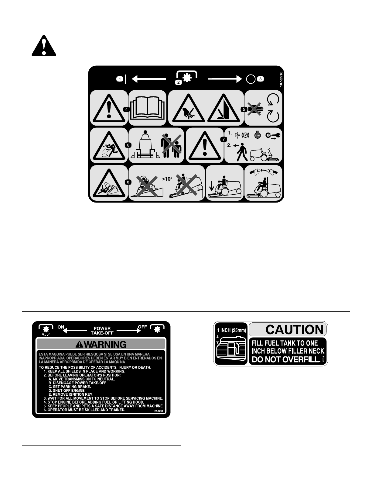
107-2918
(Models30630&30631)
*ThissafetydecalincludesaslopewarningrequiredonthemachineforcompliancetotheEuropeanLawnMowerSafetyStandardEN836:1997.Theconservativemaximum
slopeanglesindicatedforoperationofthismachineareprescribedbyandrequiredbythisstandard.
1.On3.Off5.Cuttinghazardofhand
2.Powertake-off(PTO)
4.Warning—readthe
Operator’sManual.
orfoot—stayawayfrom
movingparts.
6.Thrownobject
hazard—keepbystanders
asafedistancefromthe
machine.
7.Warning—locktheparking
brake,stoptheengine,and
removetheignitionkey
beforeleavingthemachine.
8.Tippinghazard—donot
drivethemachineona
slopegreaterthan10
degrees,lowerthecutting
unitwhendrivingdown
slopes,andiftherollbaris
installed,weartheseatbelt.
27-7310
(Models30626&30627)
27-7290
(Models30630&30631)
8
Page 9
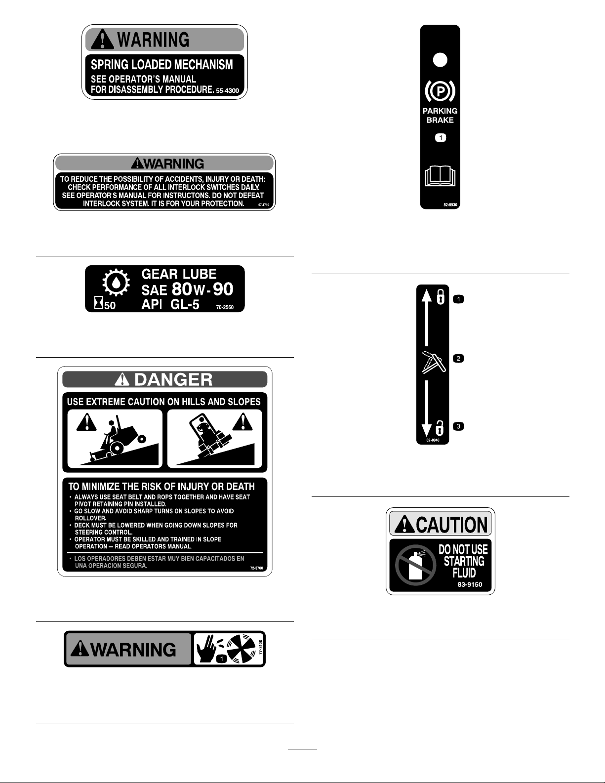
55-4300
(Models30626&30627)
67-1710
(Models30626&30627)
70-2560
(Model30627)
82-8930
(Models30626&30627)
1.Parkingbrake—readtheOperator’sManualforfurther
instructions.
82-8940
1.Locked3.Unlocked
2.Tiltsteering
72-3700
(Models30626&30627)
77-3100
(Models30626&30627)
1.Fanbladescancauseinjury—stayawayfrommovingparts.
83-9150
(Models30626&30627)
9
Page 10
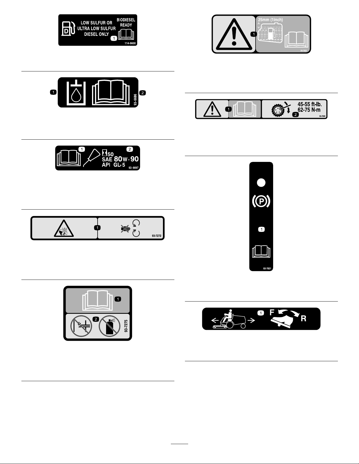
1.ReadtheOperator’sManual.
1.Hydraulicoil
2.ReadtheOperator’sManual.
1.ReadtheOperator’s
Manual.
114-9600
93-7822
(Models30630&30631
1.Caution—llfueltankto1in(25mm)belowllerneck.
ReadtheOperator’sManualforfurtherinstructions.
93-6686
93-7830
1.Caution—readtheOperator’sManualforfurther
instructions.
2.Torquewheelfastenersto45-55ft-lb(62-75N-m)
93-6697
(Model30631)
2.AddSAE80w-90(API
GL-5)oilevery50hours.
93-7272
(Models30630&30631)
1.Cutting/dismembermenthazard;fan—stayawayfromoving
parts.
93-7275
(Model30630&30631)
1.ReadtheOperator’sManual.
2.Donotusestartingaids.
93-7831
1.Parkingbrake—readtheOperator’sManualforfurther
instructions.
93-7836
1.Tomovethetractionunitforwardorbackward,depressthe
tractionpedal.
10
Page 11
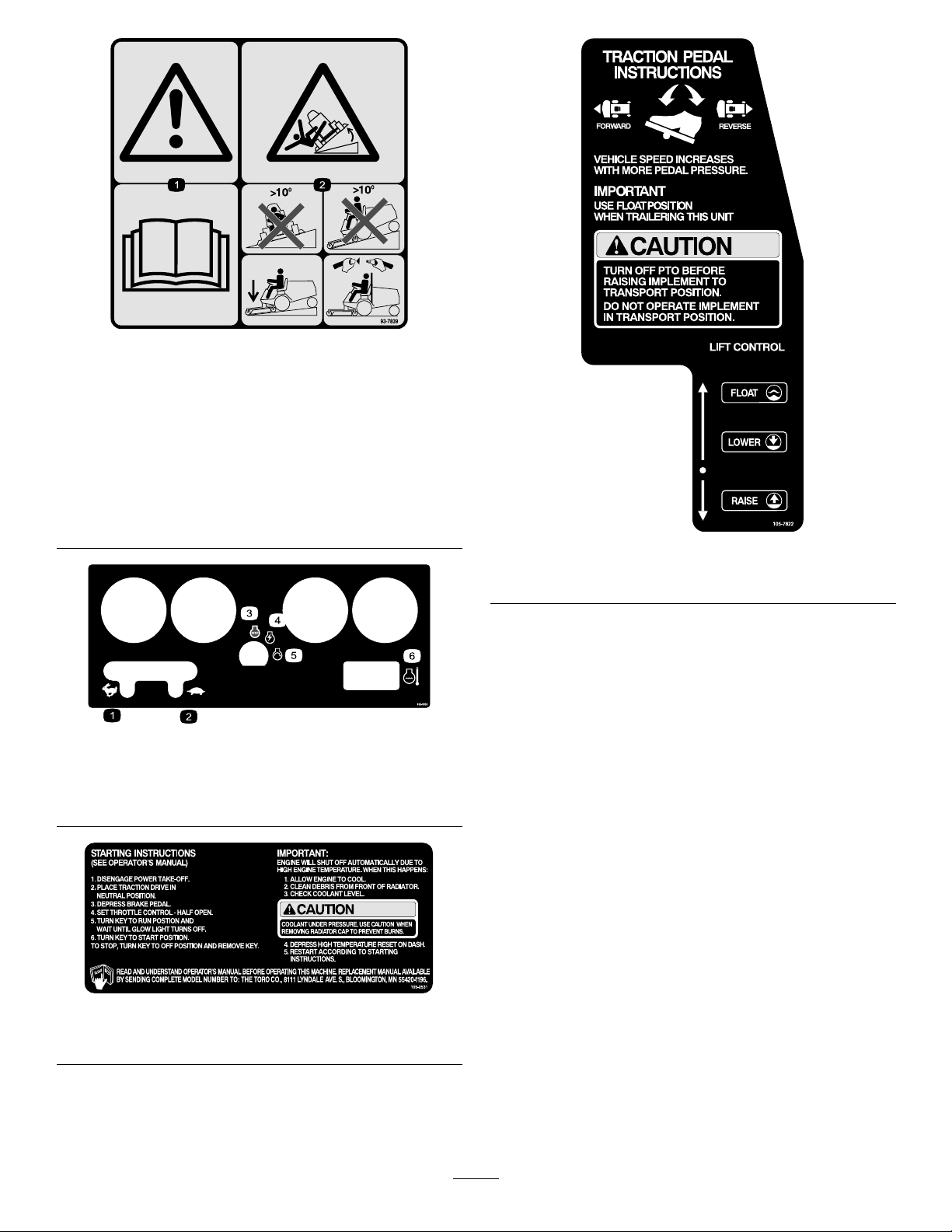
93-7839
(Model30630&30631)
*Thissafetydecalincludesaslopewarningrequiredonthemachineforcompliance
totheEuropeanLawnMowerSafetyStandardEN836:1997.Theconservative
maximumslopeanglesindicatedforoperationofthismachineareprescribed
byandrequiredbythisstandard.
1.Warning—readtheOperator’sManual.
2.Tippinghazard—donotdrivethemachineonaslope
greaterthan10degrees;whendrivingdownslopes,lower
thecuttingunit,andiftherollbarisinstalled,weartheseat
belt.
105-0056
1.Fast4.Engine—run
2.Slow
3.Engine—stop6.Enginetemperature
5.Engine—start
105-7822
(Models30626&30627)
105-2531
(Model30626&30627)
11
Page 12

105-7823
(Models30630&30631)
1.Tractiondrive—todriveforward,pressthetopofthetraction
controlpedalforwardanddown;todriveinreverse,press
thebottomofthetractioncontrolpedalrearwardanddown.
2.Warning—disengagethepowertake-off(PTO)before
raisingthecuttingunit(s).
3.Floatthecuttingunit(s)overtheground.
4.Lowerthecuttingunit(s).
5.Raisethecuttingunit(s).
106-6754
(Models30630&30631)
1.Warning—donottouchthehotsurface.
2.Cutting/dismembermenthazard,fanandentanglement
hazard,belt—stayawayfrommovingparts.
106-8120
(Models30626&30627)
1.Thrownobjecthazard—keepbystandersasafedistance
fromthemachine.
2.Cuttinghazardofhandandfoot—stayawayfrommoving
parts.
107-2927
(Models30630&30631)
1.Tostarttheengine,readtheOperator’sManual,disengage
thepowertake–off(PTO),placethetractiondrivein
neutral,pressthebrake,movethethrottlelevertotheFast
position,turnthekeytotheEngine—powerpositionuntil
theglowpluglightilluminates,andthenturnthekeytothe
Engine—startposition.
2.Toover-ridetheenginetemperaturewarning,pressthe
button.
1.Enginecoolantunder
pressure
2.Explosionhazard—read
theOperator’sManual.
106-5976
3.Warning—donottouch
4.Warning—readthe
thehotsurface.
Operator’sManual.
Manufacturer’sMark
1.Indicatesthebladeisidentiedasapartfromtheoriginal
machinemanufacturer.
12
Page 13

BatterySymbols
Someorallofthesesymbolsareonyourbattery
1.Explosionhazard
2.Nore,opename,or
smoking.
3.Causticliquid/chemical
burnhazard
4.Weareyeprotection9.Flusheyesimmediately
5.ReadtheOperator’s
Manual.
6.Keepbystandersasafe
7.Weareyeprotection;
8.Batteryacidcancause
10.Containslead;donot
distancefromthebattery.
explosivegasescan
causeblindnessandother
injuries
blindnessorsevereburns.
withwaterandgetmedical
helpfast.
discard.
13
Page 14

Setup
LooseParts
Usethechartbelowtoverifythatallpartshavebeenshipped.
ProcedureDescription
1
2
3
4
5
6
7
8
Qty.
Screw,M10x30mm
Washer4
Tierod1Installthetierod.
Bumper1
Capscrew,1/4x1/2inch
Flangenut1/4inch
Rearwheel2
Frontwheel2
Nopartsrequired
Manualtube(shippedintoolbox)
R-clamp2
Seatbelt
Bolt,7/16x1inch
Lockwasher,7/16inch
RollBar(ROPS)
Bolt,3/4x5-1/2inch
Lockwasher,3/4inch
Nut,3/4inch
4
1
1
–
1
1
2
2
1
4
4
4
Installthesteeringcylinder.
Installtherearbumper.
Installthefrontandrearwheels.
Removethebatteryfromthechassis.
Installtheseat.
Installtheseatbelt.
Installtherollbar.
Use
9
10
11
12
13
14
Nopartsrequired
Nopartsrequired
Nopartsrequired
Right-handballjoint(shippedintool
box)
Nopartsrequired
Hydraulicoillter
Partscatalog1
Operator’sManual(tractionunit)
OperatorTrainingMaterial
CerticateofQuality
Note:Determinetheleftandrightsidesofthemachine
fromthenormaloperatingposition.
Note:Somemodelsmayhavealreadybeenset-upat
factory.
–
–
–
1
–
1
2
1
1
Pushthetractionunitoffofthepallet.
Activateandchargingthebattery.
Installingthebatteryinthechassis.
Installtheballjointandconnectingthe
liftcylinder.
Installtherearweight.
Finishthesetup.
14
Page 15
1
G005678
2
1
G005679
1
2
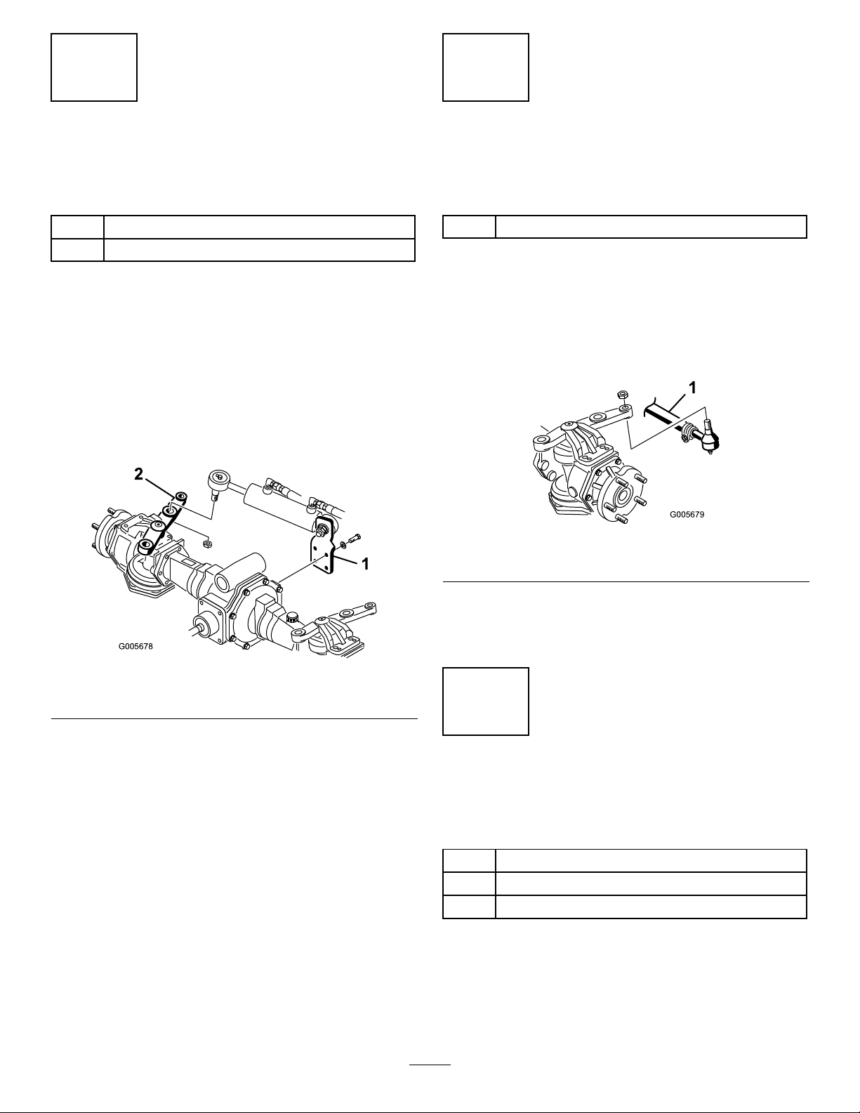
InstallingtheSteeringCylinder
(Models30627&30631only)
Partsneededforthisprocedure:
4
Screw,M10x30mm
4Washer
Procedure
1.RemovescrewandR-clampsecuringsteering
cylindertopackaging.RetainR-clampforfuture
installation.
2.Mountcylindersupportbrackettorearofaxlewith
4screws(M10x30)screwsandwashers(Figure3).
ApplyLoctite242,orequivalent,andtorquescrews
to48-60ft-lb.(65-81N-m).
InstallingtheTieRod(Models
30627&30631only)
Partsneededforthisprocedure:
1Tierod
Procedure
1.Removecotterpinsandcastlenutsfromballjoint
endsoftierod.Insertballjointendsintorearhole
ofeachaxlesteeringarm.Insertballjointsfrom
bottomofeachsteeringarm(Figure4).
Figure3
1.Cylindersupportbracket2.Steeringarm
3.Removecastlenutandcotterpinfromballjointend
ofsteeringcylinder.Insertballjointendintocenter
holeofaxlesteeringarm.Inserttheballjointfrom
thetopofthesteeringarm.
4.Secureballjointendtosteeringarmwithcastlenut
(Figure3)andtorqueitto70-90ft-lb.(94-122N-m).
Installcotterpin.
Figure4
1.Tierod
2.Secureballjointendstosteeringarmswithacastle
nutandtorqueitto40-60ft-lb.(54-81N-m).Install
acotterpin.
3
InstallingtheRearBumper
(Models30627&30631only)
Partsneededforthisprocedure:
1Bumper
1
Capscrew,1/4x1/2inch
1
Flangenut1/4inch
Procedure
1.Remove2capscrews(1/2x3/4inch),lockwashers,
andatwasherssecuringrearweighttoaxlesupport
15
(Figure5).
Page 16
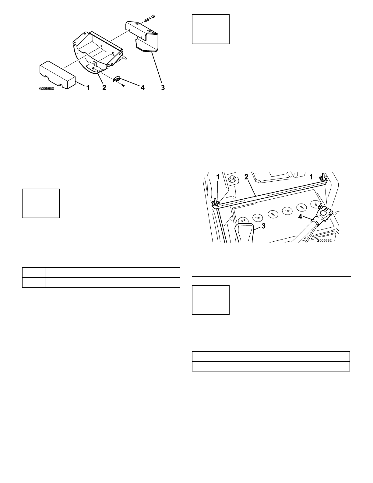
G005680
1243
Figure5
1.Rearweight3.Bumper
2.Axlesupport4.R-clamp
2.Usingcapscrews,lockwashersandatwashers
previouslyremoved,mountbumperandrearweight
toaxlesupport.
3.UsingR-clamppreviouslyremoved,securesteering
hosestoaxlesupportwithacapscrew(1/4x1/2
inch)andangenutsupplied,inlooseparts.
4
5
RemovingtheBatteryfromthe
Chassis
NoPartsRequired
Procedure
1.Releasethetwolatchesholdinginstrumentcoverin
place.Carefullyremoveinstrumentcovertoexpose
thebattery.
2.Removetwowingnutsandholddownstrapthat
securesbattery(Figure6).Liftbatteryoutofchassis.
Keepwingnutsandholddownstrapinsafeplace
forlateruse.
InstallingtheFrontandRear
Wheels
Partsneededforthisprocedure:
2Rearwheel
2Frontwheel
Procedure
1.Removeanddiscardfastenerssecuringwheelsto
packaging.
2.Removewheelnutsfromstudsonaxles.
Note:FrontwheelnutsareEnglishandrearwheel
nutsaremetric.
3.Mountwheelsandtorquemountingnutsto45-55
ft-lb.(61-75N-m).
Figure6
1.Wingnuts3.Positiveterminal
2.Holddownstrap4.Negativeterminal
6
InstallingtheSeat
Partsneededforthisprocedure:
1
Manualtube(shippedintoolbox)
2R-clamp
SeatKit,ModelNo.30623,Standard
Seat
Themachineisshippedwithouttheseatassembly.
EitheroptionalSeatKit,ModelNo.30623or30625
mustbeinstalled.
1.Looselysecure(2)R-clampstorightsideofseat
bottomwith2capscrewsandatwasherssupplied
16
Page 17
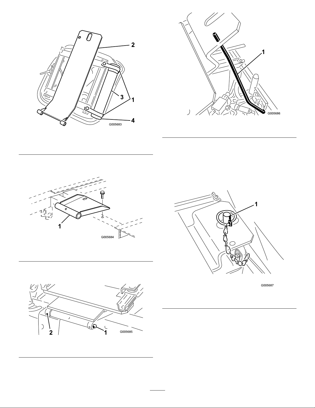
inkit(Fig.6).InstallmanualtubeintoR-clampsand
G005684
1
tightencapscrews(Figure7).
Figure7
1.R-clamps3.Manualtube
2.Seatsupport4.Cap
Figure10
1.Seatsupportrod
5.Plugwireharnessconnectorintoseatswitch
connectoronbottomofseat.
2.Mountseatpivotbrackettoframewith2ange
screwssuppliedinkit(Figure8).
Figure8
1.Seatpivotbracket
3.Mountseatandseatsupporttoseatpivotbracket
withpivotshaftandrollpin(Figure9).
6.Disengageseatsupportrodandpivotdownward.
Pivotseatdownandpushlynchpinthroughseat
latchstud.Flipwireendofpinoverlatchstud
(Figure11).
Figure11
1.Lynchpin
Figure9
1.Pivotshaft
2.Rollpin
4.Holdseatupwithseatsupportrod(Figure10).
7.Slideseatcompletelyforwardandbackwardto
ensureproperoperationandthatseatswitchwires
andconnectorsarenotpinchedordonocontactany
movingparts.
17
Page 18

SeatKit,ModelNo.30625,DeluxeSeat
withModelNo.30628SeatAdapterKit
Themachineisshippedwithouttheseatassembly.
EitheroptionalSeatKit,ModelNo.30623or30625
mustbeinstalled.
1.Mountseatsuspensionassemblyto4capscrewson
seatbottomandsecurewith4lockwashers,at
washers,andnuts(Figure12).
Figure13
1.Seatswitchwireharness
8.Disengageseatsupportrodandpivotdownward.
Pivotseatdownandpushlynchpinthroughseat
latchstud.Flipwireendofpinoverlatchstud
(Figure11).
9.Slideseatcompletelyforwardandbackwardto
ensureproperoperationandthatseatswitchwires
andconnectorsarenotpinchedordonocontactany
movingparts.
Figure12
1.Seatsuspensionassembly
2.R-clamps
3.Lockwasher ,atwasher,
andnut
2.Looselysecure2R-clampstorightsideofseat
bottomwith2capscrewsandatwasherssupplied
inkit(Figure12).InstallmanualtubeintoR-clamps
andtightencapscrews(Figure12).
3.Mountseatsupportoverfourthreadedstudsatthe
bottomofseatsuspensionassemblyandsecurein
placewithangenuts(Figure12).
4.Mountseatpivotbrackettoframewith(2)ange
screwssuppliedinkit(Figure8)
5.Mountseatandseatsupporttoseatpivotbracket
withpivotshaftandrollpin(Figure9).
6.Holdseatupwithseatsupportrod(Figure10).
7.Routeseatswitchharnessthroughholesinseat
supportandseatsuspension(Figure13).Plugwire
harnessconnectorintoseatswitchconnectoron
bottomofseat.
4.Manualtube
5.Cap
6.Seatsupport
7
InstallingtheSeatBelt
Partsneededforthisprocedure:
1
Seatbelt
2
Bolt,7/16x1inch
2
Lockwasher,7/16inch
Procedure
Installseatbelttoholesinbackofseatwith2bolts(7/16
x1inch)andlockwashers(Figure14).Tightensecurely.
Important:Mountthelatchsideofthebelttothe
rightsideoftheseat.
18
Page 19

9
PushingtheTractionUnitOff
ofthePallet
NoPartsRequired
Figure14
1.Seatbelt
8
InstallingtheRollBar
Partsneededforthisprocedure:
1
RollBar(ROPS)
4
Bolt,3/4x5-1/2inch
4
Lockwasher,3/4inch
4
Nut,3/4inch
Procedure
1.Lowerrollbarontoframe,aligningmountingholes
asshowninFigure15.
2.Securerollbartoframewith4bolts(3/4x5-1/2
inch),lockwashers,andnuts(Figure15).Tighten
securely.
Procedure
1.Reachinandrotatebypassvalveontransmission
(Figure16)counterclockwise1/2to1turn.Opening
thevalveopensaninternalpassageinthepump,
therebybypassingtransmissionoil.Becauseuid
isbypassed,themachinecanbepushedwithout
damagingthetransmission.
Figure16
1.Bypassvalve
2.Liftmachineovershippingbracesandpushmachine
offpallet.
3.Closebypassvalvebyrotatingitclockwiseuntilitis
securelyseated.Donotexceed5to8ft-lb.(7to11
N-m).Donotstartenginewhenvalveisopen.
1.Rollbar
Figure15
10
ActivatingandChargingthe
Battery
NoPartsRequired
Procedure
Useonlyelectrolyte(1.265SpecicGravity)toll
batteryinitially.
1.Removethebatteryfromthemachine.
Important:Donotaddelectrolytewhilethe
batteryisinthemachine.Youcouldspillit,
causingcorrosion.
19
Page 20

2.Cleanthetopofthebatteryandremovethevent
caps(Figure17).
Figure17
3.Carefullylleachcellwithelectrolyteuntiltheplates
arecoveredwithabout1/4inch(6mm)ofuid.
Note:Afterthebatteryhasbeenactivated,add
onlydistilledwatertoreplacenormalloss,although
maintenance–freebatteriesshouldnotrequirewater
undernormaloperatingconditions.
Warning
CALIFORNIA
Proposition65Warning
Batteryposts,terminals,andrelated
accessoriescontainleadandleadcompounds,
chemicalsknowntotheStateofCalifornia
tocausecancerandreproductiveharm.
Washhandsafterhandling.
Batteryterminalsormetaltoolscouldshort
againstmetaltractorcomponentscausing
sparks.Sparkscancausethebatterygassesto
explode,resultinginpersonalinjury.
Figure18
4.Allowapproximately20to30minutesforthe
electrolytetosoakintotheplates.Rellasnecessary
tobringtheelectrolytetowithinabout1/4inch(6
mm)ofthebottomofthellwell(Figure18).
Chargingthebatteryproducesgassesthatcan
explode.
Neversmokenearthebatteryandkeepsparks
andamesawayfrombattery.
•Whenremovingorinstallingthebattery,do
notallowthebatteryterminalstotouchany
metalpartsofthetractor.
•Donotallowmetaltoolstoshortbetween
thebatteryterminalsandmetalpartsofthe
tractor.
5.Connecta3to4ampbatterychargertothebattery
posts.Chargethebatteryatarateof3to4amps
untilthespecicgravityis1.250orhigherandthe
temperatureisatleast60degreesF(16degreesC)
withallcellsgasingfreely.
6.Whenthebatteryischarged,disconnectthecharger
fromtheelectricaloutletandbatteryposts.
20
Page 21

andsliderubberbootoverpositiveterminal
(Figure6).
11
InstallingtheBatteryinthe
Chassis
NoPartsRequired
Procedure
Batteryterminalsormetaltoolscouldshort
againstmetaltractorcomponentscausing
sparks.Sparkscancausethebatterygassesto
explode,resultinginpersonalinjury.
•Whenremovingorinstallingthebattery,do
notallowthebatteryterminalstotouchany
metalpartsofthetractor.
•Donotallowmetaltoolstoshortbetween
thebatteryterminalsandmetalpartsofthe
tractor.
5.Installtheinstrumentcoverandlockthetwolatches.
12
InstallingtheBallJointand
ConnectingtheLiftCylinder
Partsneededforthisprocedure:
1
Right-handballjoint(shippedintoolbox)
Procedure
Note:Balljointsarenotrequiredforallimplements;
refertoimplementoperator’smanualforrequirements.
1.Threadjamnutfullyontoright-handballjoint.
2.Screwballjointintorighthandpusharmuntilcenter
ofballjointis2-3/8inch(60mm)awayfromfront
ofpusharm(Figure19).Donottightenjamnut.
1.Installbatteryandsecurewithholddownstrapand
wingnuts(Figure6).Removetapeoverendsofeach
cable.
2.Slidethered,positivebatterycable(Figure6)onto
positivebatterypostandtightennutsecurely .
Incorrectbatterycableroutingcoulddamage
themachineandcablescausingsparks.Sparks
cancausethebatterygassestoexplode,
resultinginpersonalinjury.
•Always
batterycablebeforedisconnectingthe
positive(red)cable.
•Always
cablebeforeconnectingthenegative(black)
cable.
3.Slidetheblack,negativebatterycable(Figure6)onto
negativebatterypostandtightennutsecurely.
disconnect
connect
thenegative(black)
thepositive(red)battery
Figure19
1.Jamnut
2.Balljointmount4.Right-handpusharm
Suddenreleaseofthespring-loadedpusharms
couldcauseinjury.
Acquirethehelpofanotherpersontohelppush
thearmsdownduringinstallationoftheball
jointsorotherimplements.
3.2-3/8inch(60mm)
4.CoatbothbatteryconnectionswitheitherGrafo
112X(skin-over)grease,ToroPartNo.505-47,
petroleumjellyorlightgreasetopreventcorrosion
3.Haveahelperpushdownontheleftpusharm.
Theninserta2x4inch(51x102mm)blockof
woodbetweentheframeandtopofthepusharm
(Figure20).Screwballjointintolefthandpusharm
21
Page 22

untilcenterofballjointis2-3/8inch(60mm)away
fromfrontofpusharm(Figure20).Donottighten
jamnut.
Figure20
1.Jamnut4.Balljointmount
2.2x4inch(51x102mm)
block
3.Left-handpusharm
5.2-3/8inch(60mm)
5.Removespringpinfromcylinderpinandslide
cylinderpinoutofcylinder.
6.Raisefrontofliftarmuntilholeinmovableend
ofcylinderlinesupwithholesinliftarmbrackets.
Usecautionasliftarmisspring-loaded.Holdparts
togetherwithcylinderpin,springpin,andcotterpin.
Cotterpinmustbetotheoutside.
7.Installimplement;refertoimplementOperator’s
Manualforproperinstallationprocedures.
4.Carefullyremove2x4inch(51x102mm)blockof
woodfrombetweenframeandpusharm.
13
InstallingtheRearWeight
NoPartsRequired
Procedure
TocomplywithCENstandardEN836:1997,ISOstandard5395:1990andANSI/OPEIB71.4–2004Standard,rear
weightmustbeaddedtorearoftwowheeldrivetractionunits.Usechartbelowtodetermineweightrequirements.
OrderpartsfromyourlocalAuthorizedToroDistributor.Noadditionalweightisrequiredonfourwheeldrive
models.
Note:Arearweightkit,partno.24–5780issuppliedwithModelNo.30630.
TwoWheelDrive
72″SideDischarge
(ModelNo.30722)
72″RearDischarge
(ModelNo.30710)
Guardian72″Recycler
(ModelNo.30716)
CuttingUnit
Description
RearWeight
Required
70lb.24–5780
70lb.24–5780
70lb.24–5780
WeightPart
Number
WeightDescription
RearWeightKit(two35lb.weightsand
mountinghardware)
RearWeightKit(two35lb.weightsand
mountinghardware)
RearWeightKit(two35lb.weightsand
mountinghardware)
Qty.
1
1
1
22
Page 23

•OperatorTrainingMaterial.Reviewbeforeoperating
themachine.
14
FinishingtheSetup
Partsneededforthisprocedure:
1
Hydraulicoillter
1Partscatalog
2
Operator’sManual(tractionunit)
1
OperatorTrainingMaterial
1
CerticateofQuality
Procedure
CheckingtheTirePressure
Thetiresareover-inatedforshipping.Therefore,
releasesomeoftheairtoreducethepressure.Correct
airpressureinthefrontandreartiresis21psi(145kPa).
CheckingtheT orqueoftheFrontWheelNuts
•CerticateofQuality:Saveforreference.
Failuretomaintainpropertorqueofthefront
wheelnutscouldresultinfailure,lossofwheel,
orpersonalinjury.
Torquethefrontwheelnutsto45–55ft-lb.
(61–75N-m)after1–4hoursofoperationand
againafter10hoursofoperation.Torqueevery
250hoursthereafter.
GreasingtheTractionUnit
Beforethemachineisoperated,itmustbegreased
toassureproperoperatingcharacteristics;referto
LubricationMaintenance.Failuretogreasethemachine
willresultinprematurefailureofcriticalparts.
Note:Aftersetuphasbeencompleted,remove
protectiveedging(usedforshipping)fromfenders.
Reviewthefollowinglooseparts
•Hydraulicoillter
Changeafter10hours
•Partscatalog:
Saveforreference.
•Operator’sManual(tractionunit)Readbefore
operatingthemachine.
23
Page 24

ProductOverview
Figure21
1.Tractionpedal4.Parkingbrakeknob
2.Turnpedals5.Tiltsteeringcontrol
3.Brakepedal
TurnPedals
Theleftandrightturnpedals(Figure21)areconnected
totheleftandrightfrontwheelbrakessincebothbrakes
workindependentlyofeachother.Thebrakescanbe
usedtoturnsharplyortoincreasetractionifonewheel
tendstoslipwhileoperatingonahillside.However,wet
grassorsoftturfcouldbedamagedwhenbrakesare
usedtoturn.
TiltSteeringControl
Thetiltsteeringcontrolisaleveronrightsideofsteering
column(Figure21).Pullleverrearwardtoadjuststeering
wheeltodesiredforeoraftoperatingpositionandpush
leverforwardtolockadjustment.
Donotleaveleverinunlockedposition.
BrakePedal
Controls
TractionPedal
Thetractionpedal(Figure21)hastwofunctions;one
istomakethemachinemoveforward,theotheristo
makeitmovebackward.Usingtheheelandtoeofthe
rightfoot,depresstopofpedaltomoveforwardand
bottomofpedaltomovebackward.Groundspeed
isproportionatetohowfarpedalisdepressed.For
maximumgroundspeedwithnoload,tractionpedal
mustbefullydepressedwhilethrottleisinFAST
position.Maximumspeedforwardisapproximately9.5
mph(15km/h).Togetmaximumpowerunderheavy
loadorwhenascendingahill,havethrottleinFAST
positionwhiledepressingtractionpedalslightlytokeep
enginerpmhigh.Whenenginerpmbeginstodecrease,
releasetractionpedalslightlytoallowenginerpmto
increase.
Whenfootisremovedfromthetractionpedal,
machineshouldstop;itmustnotcreepineither
direction.Ifmachinedoescreep,donotoperate
untilneutralassemblyhasbeenrepairedand
adjusted;refertoAdjustingTractionDrivefor
Neutral.
Whenevertheengineisshutoff,theparkingbrake
(Figure21)mustbeengagedtopreventaccidental
movementofthemachine.
Thehydrostatictransmissionwillnot,atanytime,act
asaparkingbrakeforthemachine.T oengageparking
brake,pushdownfullyonbrakepedalandpullparking
brakeknobout;thenreleasethepedal.Torelease
parkingbrake,depressbrakepedaluntilparkingbrake
knobretracts.Tostopquickly ,removerightfootfrom
tractionpedalanddepressthebrakepedal.Topermit
straightstops,brakecablesmustbeevenlyadjusted.
LiftLever
Thehydraulicliftlever(Figure22)hasthreepositions:
FLOAT,TRANSPORT,andRAISE.Tolower
implementtotheground,moveliftleverforwardinto
detent,whichistheFLOATposition.TheFLOAT
positionisusedforoperationandalsowhenmachine
isnotinoperation.Toraiseimplement,pullliftlever
backwardtotheRAISEposition.Afterimplementis
raised,allowliftlevertomovetotheTRANSPORT
position.Normally,implementshouldberaisedwhen
drivingfromoneworkareatoanother,exceptwhen
descendingsteepslopes.
24
Page 25

Theexposed,rotatingbladesofthecuttingunit
orotherimplementsarehazardous.
FuelGauge
Thefuelgauge(Figure23)indicatesquantityoffuel
remaininginfueltank.
Neverraiseacuttingunitorimplementwhile
thebladesorothercomponentsarerotating.
Figure22
1.Liftlever
PTOLever
ThePTOlever(Figure23)hastwopositions:ON
(engage)andOFF(disengage).SlowlypushPTOlever
fullyforwardtoONpositiontostarttheimplement
orcuttingunitblades.Slowly,pullleverbackwardto
OFFpositiontostopimplementoperation.Theonly
timePTOlevershouldbeintheONpositioniswhen
implementorcuttingunitisdowninoperatingposition.
HourMeter
Thehourmeter(Figure23)registersaccumulatedhours
ofengineoperation.
OilPressureWarningLight
Theoilpressurewarninglight(Figure23)glowswhen
oilpressureinenginedropsbelowasafelevel.Iflow
oilpressureeveroccurs,stopengineanddeterminethe
cause.Repairthedamagebeforestartingtheengine
again.
ChargeIndicator
Illuminateswhensystemchargingcircuitmalfunctions
(Figure23).
EngineCoolantTemperatureWarning
Light
Thelightilluminatesandengineshutsdownwhen
coolantreachesaexcessivelyhightemperature
(Figure23).
TemperatureGauge
Thetemperaturegauge(Figure23)registersthe
temperatureofthecoolantinthecoolingsystem.If
temperatureofcoolantgetstoohightheenginewillshut
offautomatically .
Figure23
1.PTOlever7.Chargeindicator
2.Fuelgauge8.Temperaturegauge
3.Hourmeter9.Temperatureoverride
4.Oilpressureindicator
5.Enginetemperature11.Throttlecontrol
6.Glowplugindicator
switch
10.Keyswitch
12.Batterycover
TemperatureOverrideSwitch
Pressandholdoverrideswitchtostartengineafter
hightemperatureshutdown.Useonlyforemergency
operation.
GlowPlugIndicator
Whenlit,indicatesglowplugsareon(Figure23).
KeySwitch
Threepositions:OFF ,ON/PreheatandSTART
(Figure23).
ThrottleControl
Thethrottle(Figure23)isusedtooperateengineat
variousspeeds.Movingthrottleforwardincreases
enginespeed—FAST;backwarddecreasesengine
speed—SLOW .Thethrottleregulatesthespeedofthe
25
Page 26

cutterbladesorotherimplementcomponentsand,in
conjunctionwithtractionpedal,controlsgroundspeed
ofthetractionunit.
SeatAdjustingLever
Toadjuststandardseat,pushlever(Figure24)backward
andslideseattothedesiredposition.Releaseleverto
lockseatinplace.Thesuspensionseatmaybeadjusted
forwardorrearwardbypullingouttheleverattheleft
sideoftheseat,slidingtheseattothedesiredposition,
andreleasingthelever.Theweightadjustmentknob
maybeadjustedforanyoperator’scomfort.
Specications
Note:Specicationsanddesignaresubjecttochange
withoutnotice.
DimensionsandWeights(approx.)
Figure24
1.Seatadjustinglever
Widthof4wheeldrivemodels(measuredfromoutsideofreartires)
Widthof2wheeldrivemodels(measuredfromoutsideoffronttires)
Lengthof4wheeldrivemodels
Lengthof2wheeldrivemodels
HeightwithROPSofallmodels78.5inches(199cm)
DryWeightof4WheelDrivemodels(withoutcuttingdeck)
DryWeightof2WheelDrivemodels(withoutcuttingdeck)
WheelBaseof4WheelDrivemodels
WheelBaseof2WheelDrivemodels
47.6inches(121cm)
46inches(1 17cm)
94inches(239cm)
91inches(231cm)
1665lb.(755kg)
1385lb.(628kg)
51inches(130cm)
49inches(124cm)
Attachments/Accessories
AselectionofToroapprovedattachmentsand
accessoriesareavailableforusewiththemachineto
enhanceandexpanditscapabilities.Contactyour
AuthorizedServiceDealerorDistributororgoto
www.Toro.comforalistofallapprovedattachments
andaccessories.
26
Page 27

Operation
Note:Determinetheleftandrightsidesofthe
machinefromthenormaloperatingposition.
BeforeOperating
HoodProp(Models30626&30627
only)
1.Positionthemachineonalevelsurface.
2.Disengagehoodlatchandopenthehood.
3.Slidebottomofhoodprop(Figure25)outof
retainingbracket.Lowerhoodprop,pivotupward,
thendownwardtopropuphood.
2.Removedipstick(Figure26),wipecleanandreinstall
dipstick.Removedipstickandcheckoillevel.Oil
levelshouldbeuptoFULLmarkondipstick.
Figure26
1.Dipstick
3.IfoilisbelowFULLmark,removellcapandadd
oiluntillevelreachesFULLmarkondipstick.DO
NOTOVERFILL.
Figure25
1.Hoodprop
CheckingtheCrankcaseOil
Theengineisshippedwithoilinthecrankcase;
however,theoillevelmustbecheckedbeforeandafter
theengineisrststarted.
Crankcasecapacityisapproximately3.25qt.(3.1l)with
thelter.
Usehigh-qualityengineoilthatmeetsthefollowing
specications:
•APIClassicationLevelRequired:CH–4,CI–4or
higher.
•Preferredoil:SAE15W–40(above0F)
•Alternateoil:SAE10W–30or5W–30(all
temperatures)
ToroPremiumEngineoilisavailablefromyour
distributorineither15W–40or10W–30viscosity.See
thepartscatalogforpartnumbers.
1.Parkmachineonalevelsurface,stopengineand
removekeyfromignitionswitch.Openhoodand
installhoodprop.
Figure27
1.Oilll
4.Installoilllcapandclosehood.
Important:Besuretokeeptheengineoillevel
betweentheupperandlowerlimitsontheoil
gauge.Enginefailuremayoccurasaresultof
overllingorunderllingtheengineoil.
FillingtheFuelTank
Useonlyclean,freshdieselfuelorbiodieselfuelswith
low(<500ppm)orultralow(<15ppm)sulfurcontent.
Theminimumcetaneratingshouldbe40.Purchase
fuelinquantitiesthatcanbeusedwithin180daysto
ensurefuelfreshness.
Fueltankcapacity:6.5U.S.gallons(25l)
Usesummergradedieselfuel(No.2–D)at
temperaturesabove20degreesF(–7degreesC)and
27
Page 28

wintergrade(No.1–DorNo.1–D/2–Dblend)below
thattemperature.Useofwintergradefuelatlower
temperaturesprovideslowerashpointandcoldow
characteristicswhichwilleasestartingandreducefuel
lterplugging.
Useofsummergradefuelabove20degreesF(–7
degreesC)willcontributetowardlongerfuelpumplife
andincreasedpowercomparedtowintergradefuel.
Tipseatforwardandpropitwiththesupportrodsoit
cannotfallaccidentally.Usingacleanrag,cleanarea
aroundfueltankcap(Figure28).
Undercertainconditions,dieselfuelandfuel
vaporsarehighlyammableandexplosive.A
reorexplosionfromfuelcanburnyouand
othersandcancausepropertydamage.
•Useafunnelandllthefueltankoutdoors,
inanopenarea,whentheengineisoffand
iscold.Wipeupanyfuelthatspills.
•Donotllthefueltankcompletelyfull.Add
fueltothefueltankuntilthelevelis1/4to
1/2inch(6to13mm)belowthebottomof
thellerneck.Thisemptyspaceinthetank
allowsthefueltoexpand.
•Neversmokewhenhandlingfuel,andstay
awayfromanopenameorwherefuel
fumesmaybeignitedbyaspark.
•Storefuelinaclean,sealed,safety-approved
container.
BiodieselReady
Thismachinecanalsouseabiodieselblendedfuel
ofuptoB20(20%biodiesel,80%petrodiesel).The
petrodieselportionshouldbeloworultralowsulfur.
Observethefollowingprecautions:
Figure28
1.Fueltankcap
CheckCoolingSystem
Cleandebrisoffscreenandradiator/oilcoolerdaily ,
moreoftenifconditionsareextremelydustyanddirty.
Thecoolingsystemislledwitha50/50solution
ofwaterandpermanentethyleneglycolanti–freeze.
Checklevelofcoolantinexpansiontankatbeginning
ofeachdaybeforestartingtheengine.Capacityof
coolingsystemis6quarts(5.6l).
Ifenginehasbeenrunning,pressurized
hotcoolantcanescapewhenradiatorcapis
removedandcauseburns.
1.Checklevelofcoolantinexpansiontank.Coolant
levelshouldbebetweenthemarksonsideoftank.
•Thebiodieselportionofthefuelmustmeet
specicationASTMD6751orEN14214.
•TheblendedfuelcompositionshouldmeetASTM
D975orEN590.
•Paintedsurfacesmaybedamagedbybiodiesel
blends.
•UseB5(biodieselcontentof5%)orlesserblends
incoldweather.
•Monitorseals,hoses,gasketsincontactwithfuelas
theymaybedegradedovertime.
•Fuellterpluggingmaybeexpectedforatimeafter
convertingtobiodieselblends.
•Contactyourdistributorifyouwishformore
informationonbiodiesel.
Figure29
1.Expansiontank
2.Ifcoolantlevelislow ,removeexpansiontankcap
andreplenishthesystem.DONOTOVERFILL.
3.Installexpansiontankcap.
28
Page 29

CheckingtheHydraulicSystemFluid
IndustrySpecications:(cont'd.)
Thefrontaxlehousingactsasthereservoirforthe
system.Thetransmissionandaxlehousingareshipped
fromthefactorywithapproximately5quarts(4.7l)of
highqualityhydraulicuid.However,checkuidlevel
beforeengineisrststartedanddailythereafter.
Note:Fluidtooperatethepowersteeringissupplied
bythehydraulicsystemtransmissionchargepump.
Coldweatherstart-upmayresultin“stiff”operationof
thesteeringuntilthehydraulicsystemhaswarmedup.
Thefollowinglistisnotassumedtobeall–inclusive.
Hydraulicuidsproducedbyothermanufacturers
maybeusediftheycancrossreferencetond
anequivalenttotheproductslisted.Torowill
notassumeresponsibilityfordamagecausedby
impropersubstitutions,souseonlyproductsfrom
reputablemanufacturerswhowillstandbehindtheir
recommendation.
CheckingtheHydraulicSystem
Thefrontaxlehousingactsasthereservoirforthe
system.Thetransmissionandaxlehousingareshipped
fromthefactorywithapproximately5quarts(4.7l)of
highqualityhydraulicuid.Checkthelevelofthe
hydraulicuidbeforetheengineisrststarted
anddailythereafter.Therecommendedreplacement
uidis:
APIGL–4,AGCOPoweruid821XL,FordNewHolland
FNHA–2–C–201.00,KubotaUDT ,JohnDeereJ20C,Vickers
35VQ25andVolvoWB–101/BM.
Note:Manyhydraulicuidsarealmostcolorless,
makingitdifculttospotleaks.Areddyeadditivefor
thehydraulicsystemoilisavailablein2/3oz.(20ml)
bottles.Onebottleissufcientfor4–6gal(15–221)
ofhydraulicoil.Orderpartno.44–2500fromyour
authorizedTorodistributor.
1.Positionmachineonalevelsurface,raisethe
implement,andstoptheengine.
2.Unscrewdipstickcap(Figure30)fromtheller
neckandwipeitwithacleanrag.Screwdipstickcap
ngertightontollerneck.Unscrewthedipstick
andchecklevelofuid.Iflevelisnotwithin1/2
inch(13mm)fromthegrooveinthedipstick
(Figure30),addenoughuidtoraiseleveltogroove
mark.Donotoverllbymorethan1/2inch(13
mm)abovegroove.
ToroPremiumTransmission/HydraulicTractor
Fluid
(Availablein5gallonpailsor55gallondrums.Seeparts
catalogorTorodistributorforpartnumbers.)
Alternateuids:IftheTorouidisnotavailable,other
petroleum–basedUniversalTractorHydraulicFluids
(UTHF)maybeusedprovideditsspecicationsfall
withinthelistedrangeforallthefollowingmaterial
propertiesanditmeetsindustrystandards.Wedonot
recommendtheuseofsyntheticuid.Consultwith
yourlubricantdistributortoidentifyasatisfactory
productNote:Torowillnotassumeresponsibilityfor
damagecausedbyimpropersubstitutions,souseonly
productsfromreputablemanufacturerswhowillstand
behindtheirrecommendation.
MaterialProperties:
Viscosity,ASTMD445cSt@40C55to62
ViscosityIndexASTMD2270
PourPoint,ASTMD97
IndustrySpecications:
cSt@100C9.1to9.8
140–152
–35Fto–46F
Figure30
1.Dipstickcap
2.Groove
Important:Whenaddingoiltothehydraulic
system,useafunnelwithanewire
screen—200mesh—andensurefunneland
oilareimmaculatelyclean.Thisprocedure
preventsaccidentalcontaminationofthe
hydraulicsystem.
3.Screwdipstickllercapnger–tightontollerneck.
Itisnotnecessarytotightencapwithawrench.
4.Lowertheimplement.
CheckingtheRearAxle
(Models30627&30631only
Therearaxlehasthreeseparatereservoirswhichuse
SAE80W -90wt.gearlube.Althoughtheaxleis
29
Page 30

shippedwithlubricantfromthefactory,checkthelevel
beforeoperatingthemachine.
1.Positionthemachineonalevelsurface.
2.Removecheckplugsfromaxleandmakesure
lubricantisuptobottomofeachhole.Iflevelis
low,removellplugsandaddenoughlubricantto
bringtheleveluptothebottomofthecheckplug
holes(Figure31).
Starting/StoppingEngine
Important:Thefuelsystemmustbebledifanyof
thefollowingsituationhaveoccurred.
•Initialstartupofanewmachine.
•Enginehasceasedrunningduetolackoffuel.
•Maintenancehasbeenperformeduponfuel
systemcomponents;i.e.,lterreplaced,
separatorserviced,etc.
RefertoBleedingTheFuelSystem.
1.Ensureparkingbrakeisset,PTOswitchisin
OFFpositionandliftleverisinTRANSPORTor
FLOATposition.Removefootfromtractionpedal
andinsureitisinneutral.
Figure31
1.Checkplug
2.Fill/checkplug(oneon
eachendofaxle)
3.Fillplug
CheckBidirectionalClutchLubricant
(Models30627&30631only)
1.Positionthemachineonalevelsurface.
2.Rotateclutch(Figure32)socheckplug(shownin
12o’clockposition)ispositionedat4o’clock.
Figure32
1.Bidirectionalclutch
2.Checkplug
2.Movethrottlecontrolto1/2throttleposition.
3.TurnignitionswitchtoON/Preheatposition.
Anautomatictimerwillcontrolpreheatfor10
seconds.Afterpreheat,turnkeytoSTARTposition.
CRANKENGINEFORNOLONGERTHAN
15SECONDS.Releasekeywhenenginestarts.
Ifadditionalpreheatisrequired,turnkeytoOFF
positionthentoON/preheatposition.Repeat
processasrequired.
4.Runengineatidlespeedorpartialthrottleuntil
enginewarmsup.
Note:Movethrottleto1/2throttlepositionwhen
restartingawarmengine.
5.Whenengineisstartedforthersttime,or
afterengineoilchange,oroverhaulofengine,
transmissionoraxle,operatethemachineinforward
andreverseforonetotwominutes.Alsooperatethe
liftleverandPTOlevertoassureproperoperation
ofallparts.Turnpowersteeringwheeltotheleft
andrighttochecksteeringresponse.Thenshut
engineoffandcheckuidlevels,checkforoilleaks,
loosepartsandanyothernoticeablemalfunctions.
3.Removecheckplug.Fluidlevelshouldbeupto
holeinclutch.Ifuidlevelislow ,addMobilFluid
424.Clutchshouldbeapproximately1/3full.
4.Installcheckplug.
Note:Donotuseengineoil(i.e.10W30)in
bidirectionalclutch.Anti-wearandextremepressure
additiveswillcauseundesirableclutchperformance.
Shutengineoffandwaitforallmovingpartsto
stopbeforecheckingforoilleaks,looseparts
orothermalfunctions.
6.Tostopengine,movethrottlecontrolbackwardto
SLOWposition,movePTOswitchtoOFFposition
androtateignitionkeytoOFF .Removekeyfrom
switchtopreventaccidentalstarting.
30
Page 31

BleedingFuelSystem
1.Parkthemachineonalevelsurface.Makesurefuel
tankisatleasthalffull.
enginedoesnotstart,airmaybetrappedbetween
injectionpumpandinjectors;refertoBleedingAir
FromInjectors.
2.Unlatchandraisehood.
Undercertainconditions,dieselfuelandfuel
vaporsarehighlyammableandexplosive.A
reorexplosionfromfuelcanburnyouand
othersandcancausepropertydamage.
•Useafunnelandllthefueltankoutdoors,
inanopenarea,whentheengineisoffand
iscold.Wipeupanyfuelthatspills.
•Donotllthefueltankcompletelyfull.Add
fueltothefueltankuntilthelevelis1inch
(25mm)belowthebottomofthellerneck.
Thisemptyspaceinthetankallowsthefuel
toexpand.
•Neversmokewhenhandlingfuel,andstay
awayfromanopenameorwherefuel
fumesmaybeignitedbyaspark.
•Storefuelinaclean,safety-approved
containerandkeepthecapinplace.
3.Opentheairbleedscrewonthefuelinjectionpump
(Figure33).
CheckingtheInterlock
Switches
Ifsafetyinterlockswitchesaredisconnected
ordamagedthemachinecouldoperate
unexpectedlycausingpersonalinjury.
•Donottamperwiththeinterlockswitches.
•Checktheoperationoftheinterlock
switchesdailyandreplaceanydamaged
switchesbeforeoperatingthemachine.
Themachinehasinterlockswitchesintheelectrical
system.Theseswitchesaredesignedtostopthe
enginewhenoperatorgetsofftheseatwhileeitherthe
PTOleverisengagedortractionpedalisdepressed.
However,operatormaygetofftheseatwhileengineis
running.AlthoughenginewillcontinuetorunifPTO
leverisdisengagedandtractionpedalisreleased,it
isstronglyrecommendedthattheenginebestopped
beforedismountingfromtheseat.
Tocheckoperationofinterlockswitches:
Figure33
1.Fuelinjectionpumpbleedscrew
4.TurnkeyinignitionswitchtotheONposition.
Electricfuelpumpwillbeginoperation,thereby
forcingairoutaroundairbleedscrew .Leavekey
inONpositionuntilsolidstreamoffuelowsout
aroundscrew .TightenscrewandturnkeytoOFF .
Note:Normally,engineshouldstartafterabove
bleedingproceduresarefollowed.However,if
1.Drivethemachineslowlytoalarge,relativelyopen
area.Lowercuttingunit,stoptheengineandapply
parkingbrake.
2.Sitonseat.MovePTOlevertoONposition.With
thetractionpedalinneutralposition,trytostart
theengine.Theengineshouldnotcrank.Ifthe
enginecranks,thereisamalfunctionintheinterlock
systemthatshouldbecorrectedbeforebeginning
operation.
3.Sitonseat.MovePTOlevertoOFFanddepress
thetractionpedal.Trytostarttheengine.The
engineshouldnotcrank.Iftheenginecranks,there
isamalfunctionintheinterlocksystemthatshould
becorrectedbeforebeginningoperation.
Donotoperatethemachinewithoutan
implementunlessthePTOdriveshaftisalso
removed.
4.Sitonseatandstarttheengine.Disengagethe
parkingbrake.Raiseofftheseatandmovethe
31
Page 32

PTOlevertoON.Theengineshouldstopwithin
2–3seconds.Iftheenginedoesnotstop,thereisa
malfunctionintheinterlocksystemthatshouldbe
correctedbeforebeginningoperation.
5.Engagetheparkingbrake.Depressthetraction
pedalwhileengineisrunningandthePTOlever
isdisengaged.Theengineshouldstopwithin2
seconds.Ifenginestops,theswitchisoperating
correctly;thus,continueoperation.Ifenginedoes
notstop,thereisamalfunctionintheinterlock
systemthatshouldbecorrectedbeforebeginning
operation.
PushingorTowingthe
TractionUnit
Inanemergency,thetractionunitcanbepushedor
towedforaveryshortdistance.However,T orodoes
notrecommendthisasstandardprocedure.
Important:Donopushortowthetractionunit
fasterthan2to3MPH(3to4.8km/h)because
transmissionmaybedamaged.Iftractionunit
mustbemovedaconsiderabledistance,transport
itonatruckortrailer.Whenevertractionunitis
pushedortowed,bypassvalvemustbeopen.
1.Reachundertractionunitandrotatebypass
valve(Figure34)1/2to1turncounterclockwise.
Openingthevalveopensaninternalpassagein
thetransmission,therebybypassingtransmission
oil.Becauseuidisbypassed,tractionunitcanbe
movedwithoutdamagingthetransmission.
OperatingCharacteristics
Practicedrivingthemachinebecauseithasahydrostatic
transmissionanditscharacteristicsaredifferentthan
manyturfmaintenancemachines.Somepointsto
considerwhenoperatingthetractionunit,cutting
unit,orotherimplementarethetransmission,engine
speed,loadonthecuttingbladesorotherimplement
components,andtheimportanceofthebrakes.
Tomaintainenoughpowerforthetractionunitand
implementwhileoperating,regulatetractionpedalto
keepenginerpmhighandsomewhatconstant.Agood
ruletofollowis:decreasegroundspeedastheloadon
theimplementincreases,andincreasegroundspeed
astheloaddecreases.
Therefore,allowtractionpedaltomovebackward
asenginerpmdecrease,anddepresspedalslowlyas
rpmincrease.Bycomparison,whendrivingfromone
workareatoanother—withnoloadandcuttingunit
raised—havethrottleinFASTpositionanddepress
tractionpedalslowlybutfullytoattainmaximum
groundspeed.
Anothercharacteristictoconsideristheoperationof
theturningpedalsthatareconnectedtothebrakes.
Thebrakescanbeusedtoassistinturningthemachine.
However,usethemcarefully,especiallyonsoftorwet
grassbecausetheturfmaybetornaccidentally.Another
benetoftheturningbrakesistomaintaintraction.
Forexample:insomeslopeconditions,theuphillwheel
slipsandlosestraction.Ifthissituationoccurs,depress
uphillturnpedalgraduallyandintermittentlyuntilthe
uphillwheelstopsslipping,thus,increasingtractionon
thedownhillwheel.
Figure34
1.Bypassvalve
2.Beforestartingengine,closebypassvalveby
rotatingitclockwiseuntilitissecurelyseated.Do
notexceed5to8ft-lb.(7to11N-m).Donotstart
enginewhenvalveisopen.
Important:Runningthemachinewithbypass
valveopenwillcausethetransmissionto
overheat.
Useextracarewhenoperatingmachineonslopes.
Alwayshaveseatpivotretainingpininstalled.Drive
slowlyandavoidsharpturnsonslopestopreventroll
overs.Thecuttingdeckmustbeloweredwhengoing
downhillforsteeringcontrol.
Thegrassdeectormustalwaysbeinstalledandin
lowestpositiononthesidedischargecuttingunit.
Carelessoperation,combinedwithterrain
angle,ricochets,orimproperlypositioned
safetyguardscanleadtothrownobjectinjuries.
Apersonorpetmaysuddenlyappearinornear
themowingarea.
Stopmowinganddonotresumemowinguntil
theareaiscleared.
32
Page 33

Beforestoppingtheengine,disengageallcontrolsand
movethrottletoSLOW .MovingthrottletoSLOW
reduceshighenginerpm,noise,andvibration.Turn
keytoOFFtostopengine.
33
Page 34

Maintenance
RecommendedMaintenanceSchedule(s)
MaintenanceService
Interval
Aftertherst2hours
Aftertherst10hours
Aftertherst50hours
Beforeeachuseordaily
Every50hours
Every100hours
Every200hours
Every250hours
MaintenanceProcedure
•T orquethefrontwheelnuts
•Checkbelttension
•CheckPTObelttension
•Changehydraulicuidlter
•T orquethefrontwheelnuts
•Changetheengineoilandlter
•CheckPTObelttension
•CheckengineRPM
•CheckthescreenandradiatorMorefrequentlyinextremelydustyanddirtyconditions
•Inspectaircleaner
•Checkbatteryconditionandelectrolytelevel
•Changetheengineoilandlter
•Inspectthehoses
•Checkbelttension
•CheckPTObelttension
•Inspectthecoolingsystemhoses
•Checkrearwheeltoe–in
•Changehydraulicuidlter
•T orquethefrontwheelnuts
•Serviceaircleanerlter
•Checkfuellinesandconnections
•Replacethefuelltercanister.
Every400hours
Every1,000hours
•Packtherearwheelbearings
•Changetherearaxleoil
•Changethebidirectionalclutchoil
•T orque,head,adjustvalvesandcheckengineRPM
•Drainandcleanfueltank
•Flushandreplacethecoolantsystemuid
•Changethehydraulicsystemuid
•Replacemovinghoses
Ifyouleavethekeyintheignitionswitch,someonecouldaccidentlystarttheengineandseriously
injureyouorotherbystanders.
Removethekeyfromtheignitionbeforeyoudoanymaintenance.
34
Page 35

DailyMaintenanceChecklist
Duplicatethispageforroutineuse.
Fortheweekof: MaintenanceCheckItem
Mon.Tues.Wed.Thurs.Fri.
CheckSafetyInterlock
Operation
CheckGrassDeectorin
DownPosition
CheckBrakeOperation
CheckFuelLevel
CheckEngineOilLevel
CheckCoolingSystemFluid
Level
CheckDrainWater/Fuel
Separator
CheckAirFilterRestriction
Indicator3
CheckRadiator&Screenfor
Debris
CheckUnusualEngine
Noises1
CheckUnusualOperating
Noises
CheckTransmissionOilLevel
CheckHydraulicHosesfor
Damage
CheckFluidLeaks
CheckTirePressure
CheckInstrumentOperation
CheckConditionofBlades
LubricateAllGreaseFittings2
Touch-upDamagedPaint
1.Checkglowplugandinjectornozzles,ifhardstarting,excesssmokeorroughrunningisnoted.
Sat.Sun.
2.Immediatelyaftereverywashing,regardlessoftheintervallisted.
3.Ifindicatorshowsred
Important:Refertoyour
NotationforAreasofConcern
Inspectionperformedby:
ItemDate
Engine Operator’ s Man ual
foradditionalmaintenanceprocedures.
Information
35
Page 36

Lubrication
Thetractionunitmustbelubricatedregularly .Ifmachine
isoperatedundernormalconditions,lubricateall
bearingsandbushingsafterevery50hoursofoperation.
Thetractionunitbearingsandbushingsthatmustbe
lubricatedare:
AllModels
•PTOshaftandyokes(3)(Figure35)
•Liftarmpivots(Figure35)
•Rightandleftpusharmballjoints(Figure35)
•Pusharmpivotbushings(Figure36)
•PTOpivothousingblocks(Figure37)
•Brakepivotbushings(Figure38)
•Engineoutputshaftbearing(Figure39)
FourWheelDriveModels
•Axletierod(2)(Figure40)
•Axlepivotpin(Figure40)
•Axlesteeringpivots(2)(Figure40)
•Cylinderrodends(4)(Figure40)
•Driveshaft(3)(Figure41)
•Clutchhousing(Figure41)
TwoWheelDriveModels
Figure36
Figure37
•Rearwheelspindlebushings(Figure42)
•Steeringplatebushings(Figure42)
•Axlepinbushing(Figure42)
Note:Applygreasetobothbrakecablesatthedrive
wheelandbrakepedalends.
Figure35
Figure38
Figure39
36
Page 37

Figure40
EngineMaintenance
GeneralAirCleaner
Maintenance
ServiceInterval:Every50hours—Inspectaircleaner
Every400hours—Serviceaircleaner
lter
•Checkaircleanerbodyfordamagewhichcould
possiblycauseanairleak.Replaceadamagedair
cleanerbody .
•Servicetheaircleanerlterswhenaircleaner
indicator(Figure43)showsredorevery400
hours(morefrequentlyinextremedustyordirty
conditions).Donotoverserviceairlter.
Figure41
Figure42
Figure43
1.Aircleanerindicator
ServicingAirCleaner
1.Pulllatchoutwardandrotateaircleanercover
counter–clockwise(Figure44).
Figure44
1.Aircleanerlatch3.Dirtejectionport
2.Aircleanercover
37
Page 38

2.Removethecoverfromtheaircleanerbody.Before
removingthelter,uselowpressureair(40psi,
cleananddry)tohelpremovelargeaccumulations
ofdebrispackedbetweenoutsideofprimarylter
andthecanister.Avoidusinghighpressureairwhich
couldforcedirtthroughthelterintotheintake
tract.Thiscleaningprocesspreventsdebrisfrom
migratingintotheintakewhentheprimarylteris
removed.
3.Removeandreplacetheprimarylter(Figure45).
Cleaningoftheusedelementisnotrecommended
duetothepossibilityofdamagetotheltermedia.
Inspectthenewlterforshippingdamage,checking
thesealingendofthelterandthebody.Donotuse
adamagedelement.Insertthenewlterbyapplying
pressuretotheouterrimoftheelementtoseatitin
thecanister.Donotapplypressuretotheexible
centerofthelter.
4.Cleanthedirtejectionportlocatedintheremovable
cover(Figure44).Removetherubberoutletvalve
fromthecover,cleanthecavityandreplacethe
outletvalve.
5.Installthecoverorientingtherubberoutletvalvein
adownwardposition–betweenapproximately5:00
to7:00whenviewedfromtheend.
hourandradiatorcheckedeveryhourinextremelydusty
anddirtyconditions.
Note:Thissituationmaybeparticularlyprevalentifthe
reardischargecuttingunitisbeingused.Thefrontof
theradiatorcanbecleanedthoroughlybyblowingwith
compressedairfromthefansideoftheradiator.Make
suretocleanoutanydebristhatsettlestothebottom
ofthescreen.Thescreeninfrontofradiatorcanbe
removed—bylooseningwingnutsattopofscreen—to
makecleaningeasier.
ChangingEngineOilAndFilter
ServiceInterval:Aftertherst50hours
Every100hours
Checkoillevelaftereachday’soperationoreachtime
machineisused.Changeoilandlterinitiallyafter
rst50hoursofoperation;changeoilandlterafter
every100hoursofoperationthereafter.Ifpossible,run
enginejustbeforechangingoilbecausewarmoilows
betterandcarriesmorecontaminantsthancoldoil.
1.Positionmachineonalevelsurface.
2.Openthehood.Setdrainpanundertheoilpanand
inlinewithdrainplug(Figure46).
Figure45
1.Primarylter
6.Resetindicator(Figure43)ifshowingred.
CleaningtheRadiatorand
Screen
Thescreenandfrontoftheradiatormustbekeptclean
topreventtheenginefromoverheating.Normally,check
thescreenandfrontofradiatordailyand,ifnecessary,
cleananydebrisofftheseparts.However,itwillbe
necessarytocheckandtocleanthescreeneachquarter
Figure46
1.Drainplug
3.Cleanareaarounddrainplug.
4.Removeoildrainplugandallowoiltoowinto
drainpan.
5.Removeandreplaceoillter(Figure47).
38
Page 39

Figure47
1.Oillter
6.Afteroilisdrained,reinstalldrainplugandwipeup
anyoilthatisspilled.
7.Fillcrankcasewithoil;refertoCheckCrankcaseOil.
BleedingAirFromInjectors
Note:Thisprocedureshouldbeusedonlyiffuel
systemhasbeenpurgedofairthroughnormalpriming
proceduresandenginewillnotstart;refertoBleeding
FuelSystem.
1.LoosenthepipeconnectiontotheNo.1injector
nozzleandholderassemblyatinjectionpump
(Figure48).
FuelSystem
Maintenance
Note:RefertoFillFuelTankWithDieselFuelfor
properfuelrecommendations.
Undercertainconditions,dieselfuelandfuel
vaporsarehighlyammableandexplosive.A
reorexplosionfromfuelcanburnyouand
othersandcancausepropertydamage.
•Useafunnelandllthefueltankoutdoors,
inanopenarea,whentheengineisoffand
iscold.Wipeupanyfuelthatspills.
•Donotllthefueltankcompletelyfull.Add
fueltothefueltankuntilthelevelis1inch
(25mm)belowthebottomofthellerneck.
Thisemptyspaceinthetankallowsthefuel
toexpand.
•Neversmokewhenhandlingfuel,andstay
awayfromanopenameorwherefuel
fumesmaybeignitedbyaspark.
Figure48
1.No.1injectornozzle
2.MovethrottletoFASTposition.
3.TurnkeyinkeyswitchtoSTARTpositionand
watchfuelowaroundconnector.TurnkeytoOFF
positionwhensolidowisobserved.
4.Tightenpipeconnectorsecurely
5.Repeatstepsonremainingnozzles.
•Storefuelinaclean,safety-approved
containerandkeepthecapinplace.
FuelTank
ServiceInterval:Every1,000hours
Drainandcleanfueltankevery1000hoursoperationor
every2years,whichevercomesrst.Also,drainand
cleantankiffuelsystembecomescontaminatedorif
machineistobestoredforanextendedperiod.Use
cleandieselfueltoushoutthetank.
FuelLinesandConnections
ServiceInterval:Every400hours
Checklinesandconnectionsevery400hoursoryearly,
whichevercomesrst.Inspectfordeterioration,damage
orlooseconnections.
ServicingtheWaterSeparator
ServiceInterval:Every400hours
Drainwaterorothercontaminantsfromwaterseparator
(Figure49)daily.Replaceltercanisterafterevery400
hoursofoperation.
1.Placeacleancontainerunderthefuellter.
39
Page 40

2.Loosenthedrainplugonthebottomofthelter
canister.
Figure49
1.Waterseparatorltercanister
ElectricalSystem
Maintenance
Fuses
Thefuseblockislocatedbelowcontrolpanel.
3.Cleantheareawheretheltercanistermounts.
4.Removetheltercanisterandcleanthemounting
surface.
5.Lubricatethegasketontheltercanisterwithclean
oil.
6.Installtheltercanisterbyhanduntilthegasket
contactsmountingsurface,thenrotateitan
additional1/2turn.
7.Tightenthedrainplugonthebottomofthelter
canister.
Figure50
1.Fuseblock2.Accessoryconnector
ServicingtheBattery
ServiceInterval:Every50hours
Batteryposts,terminals,andrelatedaccessories
containleadandleadcompounds,chemicals
knowntotheStateofCaliforniatocausecancer
andreproductiveharm.
handling .
Important:Beforeweldingonthemachine,
disconnectgroundcablefromthebatterytoprevent
damagetotheelectricalsystem.
Note:Checkbatteryconditionandelectrolytelevel
weeklyorafterevery50hoursofoperation.Keep
terminalsandentirebatterycasecleanbecauseadirty
batterywilldischargeslowly.Tocleanthebattery,wash
theentirecasewithsolutionofbakingsodaandwater.
Rinsewithclearwater.Coatthebatterypostsandcable
connectorswithGrafo112X(skin-over)grease(Toro
PartNo.505-47)orpetroleumjellytopreventcorrosion.
W ash hands after
40
Page 41

DriveSystem
Maintenance
AdjustingRearWheelToe–in
(Models30626&30630only)
ServiceInterval:Every200hours
Therearwheelsshouldnottoe–inortoe–outwhen
theyareadjustedcorrectly.Tochecktherearwheel
toe–in,measurethecenter–to–centerdistanceatwheel
hubheight,infrontandinbackofthereartires.Ifthe
wheelstoe–inortoe–out,anadjustmentisrequired.
1.Rotatethesteeringwheelsorearwheelsarestraight
ahead.
2.LoosenthejamnutsonbothtierodsAdjustbothtie
rodsuntilcenter-to-centerdistanceatfrontandback
ofrearwheelsisthesame(Figure51).
3.Whenrearwheelsareadjustedcorrectly,tightenjam
nutsagainsttierods.
Figure51
1.Steeringplate
Figure52
1.Steeringstop(Rightside
shown)
2..090inchclearance
AdjustingtheRearWheel
Bearings(Models30626&
30630only)
ServiceInterval:Every400hours
1.Jackuprearofmachineuntilwheelisoffshopoor.
Usejackstandsorblockthemachinetopreventit
fromaccidentallyfalling.
2.Removedustcapfromendofwheelspindle.Also
removecotterpinsecuringretainer(Figure53).
AdjustingSteeringStops
(Models30627&30631only)
Therearaxlesteeringstopshelppreventovertravelof
thesteeringcylinderincaseofimpactonrearwheels.
Thestopsshouldbeadjustedsothereis.090inch
clearancebetweentheboltheadandtheknuckleonthe
axlewhenthesteeringwheeliscompletelyturnedleft
orright.
Threadtheboltsinoroutuntilthe.090inchclearanceis
attained(Figure52).
Figure53
1.Dustcup4.Jamnut
2.Cotterpin
3.Nutretainer
3.Tightenthejamnut(Figure53)toapproximately
75–100in–lbsusingahandwrench.
4.Turnthewheelhubtoseatthebearings.
5.Loosenthejamnutuntilitisawayfromthe
atwasherandthewheelhubhasendplay.
41
5.Flatwasher
Page 42

6.Tightenthejamnutto15–20in–lbswhilerotating
thewheelhub.
7.Placethenutretaineroverthejamnut.Ifthecotter
pinholeisnotalignedwiththeretainerslot,remove
theretainernutandreorientateuntilalignment
occurs.
8.Insertcotterpin.Thewheelhubmustnothaveany
freeplay .
9.Installdustcaponendofwheelspindle.
10.Removejackstandsandlowermachinetoshopoor.
Figure55
1.Mountingbolt(4)
ChangingRearAxleLubricant
(Models30627&30631only)
ServiceInterval:Every400hours
Afterevery400hoursofoperation,theoilintherear
axlemustbechanged.
1.Positionmachineonalevelsurface.
2.Cleanareaaroundthedrainplugs(Figure54).
Figure54
1.Drainplugs
ChangingBidirectionalClutch
Lubricant(Models30627&
30631only)
ServiceInterval:Every400hours
Afterevery400hoursofoperation,theoilinthe
bidirectionalclutchmustbechanged.
1.Positionthemachineonalevelsurface.
2.Cleanareaaroundcheckplugonbidirectionalclutch.
3.Rotateclutchsocheckplugispositioneddownward
(Figure56).
3.Removeplugallowingoiltodrainintodrainpans.
4.Afteroilisdrained,applythreadlocking
compoundondrainplugthreadsandreinstall
inaxle.
5.Fillaxlewithlubricant;refertoCheckRearAxle.
CheckingSteeringCylinder
BoltTorque(Models30627&
30631only)
Checkthesteeringcylindermountingbolttorqueevery
200hoursofoperation.
1.Positionthemachineonalevelsurface.
2.Checkthetorqueonthesteeringcylindermounting
bolts.Torqueshouldbe48–60ft-lb.(65-81N-m).
Figure56
1.Bidirectionalclutch
4.Removecheckplugallowingalllubricanttoow
intodrainpan.
5.Rotateclutchsocheckplugispositionedat4
O’clock.
6.AddMobilFluid424untillubricantlevelisupto
holeinclutch.Clutchshouldbeapproximately1/3
full.
7.Installcheckplug.
Note:Donotuseengineoil(i.e.10W30)in
bidirectionalclutch.Anti–wearandextremepressure
additiveswillcauseundesirableclutchperformance.
42
2.Checkplug
Page 43

CoolingSystem
Maintenance
CleaningRadiatorAndScreen
ServiceInterval:BeforeeachuseordailyMore
frequentlyinextremelydustyand
dirtyconditions
Every100hours
Topreventtheenginefromoverheating,thescreenand
radiatormustbekeptclean.Normally,checkthescreen
andradiatordailyand,ifnecessary,cleananydebrisoff
theseparts.However,itwillbenecessarytocheckand
cleanthescreenandradiatorfrequentlyinextremely
dustyanddirtyconditions.
Note:Ifengineshutsoffduetooverheating,rstcheck
theradiatorandscreenforexcessivebuildupofdebris.
Tothoroughlycleantheradiator:
1.Removethescreen.
2.Workingfromthefansideoftheradiator,either
spraytheradiatorwithawaterhoseorblowwith
compressedair.
3.Aftertheradiatoristhoroughlycleaned,cleanout
debristhatmayhavecollectedinthechannelatthe
radiatorbase.
4.Cleanandinstallthescreen.
Figure57
1.Draincock
Whenllingtheradiator,levelofcoolantmustbeabove
thecoreand1inch(25mm)belowbottomofller
neck.DONOTOVERFILL.Alwaysinstallradiatorcap
(Figure58)securely .
Note:Inspectthehosesafterevery100hoursof
operation.
ChangingCoolantInCooling
System
ServiceInterval:Every1,000hours
Capacityofcoolingsystemisapproximately6quarts
(5.7L).Thecoolingsystemmustbelledwitha
50/50solutionofwaterandpermanentethyleneglycol
anti-freeze.Afterevery1000hoursofoperationortwo
years,drainthecoolantfromtheradiatorbyopeningthe
draincock(Figure57).Aftercoolantisdrained,ush
theentiresystemandrellitwitha50/50solutionof
waterandanti-freeze.
Figure58
1.Radiatorcap
Levelofcoolantinexpansiontank(Figure59)shouldbe
betweenthemarksonsideoftank.
Figure59
1.Expansiontank
43
Page 44

BrakeMaintenance
G005742
1
AdjustingtheBrakes
Adjusttheservicebrakeswhenthereismorethan1inch
(25mm)of“freetravel”oftheturnpedals,orwhenthe
brakesdonotworkeffectively.Freetravelisthedistance
thebrakepedalmovesbeforebrakingresistanceisfelt.
Thebrakesshouldonlyneedadjustingafterconsiderable
use.Theseperiodicadjustmentscanbeperformed
wherethebrakecablesconnecttothebrakepedal
mount.Whenthecablesarenolongeradjustable,
thestarnutontheinsideofthebrakedrummustbe
adjustedtomovethebrakeshoesoutward.However,
thebrakecablesmustbeadjustedagaintocompensate
forthisadjustment.
bottomandcenteredoverstarnutthatadjustsbrake
shoes(Figure61).
1.Toreducefreetravelofturnpedals—tightenthe
brakes—loosenfrontnutonthreadedendofbrake
cable(Figure60).Thentightenrearnuttomove
cablebackwarduntilturnpedalshave1/2to1inch
(13to25mm)offreetravel.Tightenfrontnutafter
brakesareadjustedcorrectly.
Figure60
1.Jamnuts
Figure61
1.Slot
6.Usingabrakeadjustingtoolorscrewdriver,
rotatestarnut(Figure61)downuntilbrakedrum
(Figure62)locksbecauseofoutwardpressureof
brakeshoes(Figure62).
2.Whenadjustmentofbrakecablecannotgetfree
travelwithin1/2to1inch(13to25mm),thestarnut
insidethebrakedrummustbeadjusted.However,
beforeadjustingthestarnut,loosenbrakecablenuts
topreventunnecessarystrainonthecables.
3.Loosenvewheelnutsholdingwheelandtire
assemblyonwheelstuds.
4.Jackupmachineuntilfrontwheelisofftheshop
oor.Usejackstandsorblockthemachineto
preventitfromfallingaccidentally .
5.Removewheelnutsandslidewheelandtireassembly
offstuds.Rotatebrakedrumuntiladjustingslotisat
Figure62
1.Starnut
2.Brakeshoes
7.Loosenstarnutabout12to15notchesoruntilbrake
drumrotatesfreely.
8.Installwheelandtireassemblyonstudswithve
wheelnuts.Tightennutsto45-55ft–lb(61-75N-m).
9.Removejackstandsorblockingandlowermachine
totheshopoor.
10.Adjustthebrakecablesusingstep1.
44
Page 45

BeltMaintenance
ServicingtheEngineBelts
ServiceInterval:Aftertherst10hours
Every100hours
Checktensionofallbeltsinitiallyaftertherstdayof
operationandevery100hoursthereafter.
AlternatorBelt
1.Unlatchandopenhood.
2.Propertensionwillallow3/8inch(10mm)
deectionwhenaforceof10lbs.isappliedonthe
belt(Figure63)midwaybetweenthepulleys.
Figure64
1.Fanbeltguard
3.Beltshoulddeect1/4inch(6mm)midwaybetween
thepulleyswith5lb.force(22n)(Figure65).If
deectionisincorrect,proceedtostep4.Ifcorrect,
proceedtostep5.
Figure63
1.Alternator2.Mountingbolt
3.deectionisnot3/8inch(10mm),loosenalternator
mountingbolts.Increaseordecreasealternatorbelt
tensionandtightenbolts.Checkdeectionofbelt
againtoassuretensioniscorrect.
CoolingFanBelt
1.Unlatchandopenhood.
2.Removecapscrews(5)securingfanbeltguardand
removeguard(Figure64).
Figure65
1.1/4inch(6mm)deection
here
2.AdjustableIdlerpulley
locknut
4.Loosenlocknutsecuringadjustableidlerpulley
(Figure65).Pushidlerpulleyagainstbeltuntil
properdeectionisachievedandtightenidlerpulley
locknut(Figure65).
5.Installfanbeltguardandsecurewithcapscrews
(Figure64).Closeandlatchhood.
Toreplacebelt:
1.Followproceduresinstep1and2above.
2.Loosenlocknutsecuringadjustableidlerpulley,slide
pulleyawayfrombelt,andremovebeltfrompulleys
(Figure65).
3.Installnewbeltandadjustforpropertension.Push
idlerpulleyagainstbeltuntilbeltdeects1/4inch(6
mm)with5lb.force(22N⋅m)midwaybetweentop
45
Page 46

pulleyandstationaryidlepulley .Tightenidlerpulley
locknuttosecureadjustments(Figure65).
4.Installfanbeltguardandsecurewithcapscrews
(Figure64).Closeandlatchhood.
ControlsSystem
Maintenance
Note:Checkfanbelttensionafterrstday’ s
operation.Readjusttension,ifnecessary.Followregular
maintenancecheckprocedurethereafter.
AdjustingPTODriveBelt
Tension
ServiceInterval:Aftertherst10hours
Aftertherst50hours
Every100hours
Important:CheckPTObelttensioninitiallyafter
rst10hoursand50hoursofoperationandafter
every100hoursofoperationthereafter.
Ifbeltbeginstoslipbecauseithasstretchedorbecause
ofwornlinkageadjustasfollows:
1.Unlatchandremoveinstrumentcover.
2.MovePTOcontrollevertoONposition.
3.MeasurelengthofPTOspringbetweenat–washers
(Figure66).Thereshouldbeaspringlengthof
3-3/16inches(81mm).
AdjustingThrottle
Adjustthrottlecable(Figure67)sogovernorleveron
enginecontactslowandhighspeedsetboltsbefore
throttlelevercontactsslotincontrolpanel.
Figure67
1.Throttlecable
AdjustingTractionControl
Figure66
1.3-3/16inches(81mm)
2.PTOactuatingarm
4.Toadjust,holdheadofadjustingscrewwithwrench
(underPTOactuatingarm)andturnlocknut
(Figure66).
5.MovePTOlevertoOFFpositionandinstall
instrumentcover.
3.Locknut
Rod
1.Checktractiondriveneutralpositiontoassurefront
wheelsdonotcreep;refertoAdjustingTraction
DriveforNeutral.
2.Loosenlocknutsandadjusttractionpedalstop
screw(Figure68)toalengthof3.00inches.
Figure68
1.Tractionpedal
2.Stopscrew
46
Page 47

3.Rotatepumplevertofullforwardspeedlocation.
4.Adjustcontrolrodend(Figure69)untilthereisa
.12”gapbetweentopoftractionpedalstopscrew
andpedal.Tightenlocknuts.
Figure70
1.Switchadjustingscrew
2.Jamnut
3.Ballbearing7.Pumpplate
4.Leafsprings
5.Pumplever
6.Capscrews
Figure69
1.Controlrod
2.Frictionwheel
AdjustingTractionPedal
FrictionWheel
1.Loosentwonutssecuringtractionpedalshafton
rightsideofpedal(Figure69).
2.Rotateshafttorelocatewornsurfaceoffriction
wheelawayfromundersideoftractionpedal.
3.Tightennutstosecureshaftandwheelinposition.
AdjustingtheTractionDrive
forNeutral
1.Parkvehicleonalevelsurfaceandturnengine
off.Applytheparkingbrake,tipseatforward,and
actuatepumplever(Figure70)toensureassembly
isproperlyseatedandoperatingfreely.Correctany
discrepancy.
2.Blockrightfronttireandbothreartiressovehicle
cannotrollforwardorbackward.
3.Jackupframesoleftfrontwheelisofftheshop
oor.Useajackstandtosupporttheframe.On
fourwheeldrivemachines,makesurethatatleast
onerearwheelisofftheground.
4.Startengineandallowittoidlefor5minutestoheat
oilintransmissiontooperatingtemperature.
5.Releaseparkingbrake;thencheckleftfrontwheel
thatisoffshopoor.Wheelmustnotberotating.
Ifwheelisrotating,proceedtostep6foran
adjustment.Ifwheelisnotrotating,proceedtostep
8.VerifytheadjustmentwiththrottleinSLOWand
FASTposition.
6.Becausethewheelisrotating,thepumpplatemust
beadjusted.Butbeforeadjustingthepumpplate,
movethrottletoSLOW .Ifwheelisrotatingforward,
loosencapscrews,andlightlytapbottomofpump
platecounterclockwise(Figure70).Bycontrast,tap
pumpplateclockwiseifwheelisrotatingbackward
(Figure70).Whenwheelstopsrotating,tighten
capscrewsholdingpumpplateagainstsideof
transmission.Verifytheadjustmentwiththrottlein
SLOWandFASTposition.
7.Shouldfrontwheelcontinuetorotate,checkfor
thefollowing:
•Ballbearingislooseorwornout(Figure70).
•Plungeroninterlockswitchissticking.
•Looseormissingfasteners.
•Wornboltsecuringpumplevertotransmission.
•Pumpleverlooseoncontrolshaft.(Correctby
applyingLoctite680toshaft.)
47
Page 48

•Weakordamagedleafsprings(Figure70).
Replace.
•Internaltransmissioncomponentmalfunction.
ContactyourlocalTorodistributorforassistance.
8.Shutengineoff.
9.Adjusttractioncontrolrod;refertoAdjustingthe
TractionControlRod.
AdjustingtheTraction
6.Connectacontinuitytesterorohmmetertoswitch
connector.WithPTOleverintheONpositionthe
switchcircuitshouldnothaveanycontinuity.If
thereiscontinuity ,recheckswitchinstallation.If
thereisnocontinuity,proceedtonextstep.
7.MovePTOlevertotheOFFposition.When
PTOleverisinitsnormal,releasedposition,the
PTOswitchshouldhavecontinuity.Ifthereisno
continuity,recheckswitchinstallation.Ifthereisno
continuity,proceedtonextstep.
InterlockSwitch
1.Adjusttransmissionforneutral;refertoAdjusting
theTractionDriveforNeutral.
2.Actuatethepumplever(Figure70)toensureall
partsareoperatingfreelyandseatedproperly.
3.Loosenjamnut.Rotateswitchadjustingscrew
(Figure70)untilthereisagapbetweenheadofscrew
andswitchbutton.
4.Rotateadjustingscrewuntilitcontactstheswitch
button.Continuetorotatethescrewuntilthecircuit
iscompleted(switch“clicks”).Aftertheswitch
clicks,rotatetheadjustingscrewanadditional1/2
turn.Tightenjamnut.
ReplacingthePTOSwitch
1.Removeinstrumentcoveranddisconnectnegative
batterycablefrombattery.
2.MovePTOleverforwardtoONposition.
3.RemovebootfrombuttonendofPTOswitch
(Figure71).Retainbootforreinstallation.Separate
switchwireconnectors.
8.Pushswitchconnectorstogether.
9.Connectbatterycableandinstallinstrumentcover.
AdjustingtheParkingBrake
InterlockSwitch
1.Gapbetweenparkingbrakeshaftpivotpaddleand
bottomofinterlockswitch(Figure72)shouldbe
approximately1/16”(Paddlemustnotcontact
switch).
Figure72
1.Parkingbrakeinterlock
switch
2.Parkingbrakeshaftpivot
paddle
3.Wireharnessconnector
Figure71
4.Removefrontjamnutsecuringswitchtomounting
bracketandremoveswitch.
5.InstallnewPTOswitchtomountingbracket.Adjust
switchsoitisdepressed1/2inch(13mm)when
PTOleverismovedtoOFFposition.Tightenjam
nutsto75in-lb.Installboottoswitch.
Important:Switchthreadswillbedamagedif
jamnutsareovertightened.
2.Toadjustgap,loosenswitchmountingscrews,adjust
gapandtightenscrews.
3.Disconnectswitchpigtailconnectorfromwire
harness.
4.Pulluponparkingbrakeleveranddepressbrake
pedaltolockpedalintorstclickonlatch.
5.Connectacontinuitytesterorohmmetertoswitch
harnessconnector.Withparkingbrakeengaged,the
switchcircuitshouldnothavecontinuity.Ifthereis
continuity,recheckswitchorswitchinstallation.
48
Page 49

AdjustingtheTiltSteering
Control
Ifsteeringwheeltiltcontrollevermustbeadjusted,
proceedasfollows:
1.Removeknobfromparkingbrakeandselftapping
screwsfromsteeringcolumncover.Slidecoverup
steeringshafttoexposepivotbracket(Figure73).
2.Loosensmallnut,rotatepivotbracketuntilittightens
largenutbelow(Figure73).Retightensmallnut.
3.Reinstallsteeringcolumncoverandparkingbrake
knob.
HydraulicSystem
Maintenance
ReplacingtheHydraulicFluid
Filter
ServiceInterval:Aftertherst10hours
Every200hours
Thehydraulicuidlterkeepsthehydraulicsystem
relativelyfreeofcontaminantsandmustbeserviced
atregularintervals.Initially,changelterafterrst
tenhoursofengineoperation,andthereafter,after
every200hoursofoperationoryearly,whichever
comesrst.UseTorooillter,PartNo.23-9740,as
areplacement.
1.Cleanareawherehydraulicuidltermounts.
Removelterfrombase(Figure74)andcleanlter
mountingsurface.
Figure73
1.Pivotplate3.Largenut
2.Smallnut
Figure74
1.Hydraulicoillter
2.Lubricateltergasketwithpropertypeofhydraulic
uid.Thenlllterusingthesamehydraulicuid.
3.Installlterbyhanduntilgasketcontactsmounting
head.Thenrotateanadditional1/2turn.
4.Startengineandcheckforhydraulicuidleaks.
Allowenginetorunforabouttwominutessoanyair
inthesystemispurged(removed).
5.Shutengineoffandchecklevelofhydraulicsystem;
refertoCheckingtheHydraulicSystemOil.
49
Page 50

ChangingtheHydraulic
SystemFluid
ServiceInterval:Every1,000hours
Thehydraulicsystemuidmustbechangedafterevery
1000hoursofnormaloperationoreverytwoyears,
whichevercomesrst.
Therecommendedreplacementuidis:
ToroPremiumTransmission/HydraulicTractor
Fluid
(Availablein5gallonpailsor55gallondrums.Seeparts
catalogorTorodistributorforpartnumbers.)
Alternateuids:IftheTorouidisnotavailable,other
petroleum–basedUniversalTractorHydraulicFluids
(UTHF)maybeusedprovideditsspecicationsfall
withinthelistedrangeforallthefollowingmaterial
propertiesanditmeetsindustrystandards.Wedonot
recommendtheuseofsyntheticuid.Consultwithyour
lubricantdistributortoidentifyasatisfactoryproduct
Note:Torowillnotassumeresponsibilityfordamage
causedbyimpropersubstitutions,souseonlyproducts
fromreputablemanufacturerswhowillstandbehind
theirrecommendation.
MaterialProperties:
Viscosity,ASTMD445cSt@40C55to62
ViscosityIndexASTMD2270
PourPoint,ASTMD97
cSt@100C9.1to9.8
140–152
–35Fto–46F
4.Removedrainplugfromttingbetweenaxlehousing
andoillterandallowuidtoowintodrainpan
(Figure75).
Figure75
1.Drainplug
5.Installnewlter;refertosteps1–2inReplacing
HydraulicOilFilter,forproperprocedures.
6.Installdrainpluginttingbetweenaxlehousingand
lter(Figure75).
7.Removedipstickfromaxlellertube(Figure76)and
llaxletoproperlevelwithcorrecttypeofhydraulic
uid;refertotableabove.
8.Startandruntheengineatidlespeedforabouttwo
minutesandturnthesteeringwheellocktolockto
purgeairtrappedinthesystem.Shuttheengineoff.
IndustrySpecications:
APIGL–4,AGCOPoweruid821XL,FordNewHolland
FNHA–2–C–201.00,KubotaUDT ,JohnDeereJ20C,Vickers
35VQ25andVolvoWB–101/BM.
Note:Manyhydraulicuidsarealmostcolorless,
makingitdifculttospotleaks.Areddyeadditivefor
thehydraulicsystemoilisavailablein2/3oz.(20ml)
bottles.Onebottleissufcientfor4–6gal(15–221)
ofhydraulicoil.Orderpartno.44–2500fromyour
authorizedTorodistributor.
1.Startengine,parkmachineonalevelsurface,lower
implementtotheshopoor,settheparkingbrake,
andshutengineoff.Blockthetworearwheels.
2.Jackupbothsidesoffrontaxleandsupportitwith
jackstands.
3.Cleanareaaroundhydraulicuidlterandremove
lter.
9.Leavemachinesetfortwoadditionalminutes,
thenremovedipstickandcheckuidlevelinaxle
(Figure76).Iflevelislow,adduiduntillevel
matchesgrooveindipstick(Figure76).Iflevelistoo
high,removedrainplug(Figure75)anddrainuid
untillevelmatchesgrooveindipstick.
50
Page 51

Storage
TractionUnit
1.Thoroughlycleanthetractionunit,cuttingunitand
theengine,payingspecialattentiontotheseareas:
•radiatorscreen
•underneaththecuttingunit
•underthecuttingunitbeltcovers
•counterbalancesprings
•P .T.O.ShaftAssembly
•allgreasettingsandpivotpoints
2.Checkthetirepressure.Inatealltractionunittires
to21psi(145kPa).
Figure76
1.Dipstick
2.Groove
3.Remove,sharpen,andbalancethecuttingunit’s
blades.Reinstallthebladesandtorquetheblade
fastenerstospecications.
4.Checkallfastenersforlooseness;tightenas
necessary.
5.Greaseoroilallgreasettingsandpivotpoints.
Wipeupanyexcesslubricant.
6.EnsurethattheP .T.O .beltremainsinthedisengaged
positionsothattheP .T .O.beltdoesnottakea“set.”
7.Lightlysandandusetouch-uppaintonpaintedareas
thatarescratched,chipped,orrusted.Repairany
dentsinthemetalbody .
8.Servicethebatteryandcablesasfollows:
A.Removethebatteryterminalsfromthebattery
posts.
B.Cleanthebattery,terminals,andpostswitha
wirebrushandbakingsodasolution.
C.Coatthecableterminalsandbatterypostswith
Grafo112Xskin-overgrease(ToroPartNo.
505-47)orpetroleumjellytopreventcorrosion.
D.Slowlyrechargethebatteryevery60daysfor24
hourstopreventleadsulfationofthebattery.
Engine
1.Draintheengineoilfromtheoilpanandreplace
thedrainplug.
2.Removeanddiscardtheoillter.Installanewoil
lter.
3.Removellcapandadd4quarts(3.8l)ofoiluntil
levelreachesFULLmarkondipstick.DONOT
OVERFILL.
4.Starttheengineandrunatidlespeedfor
approximatelytwominutes.
5.Stoptheengine.
51
Page 52

6.Thoroughlydrainallfuelfromthefueltank,lines,
fuelpumplter,andthefuellter/waterseparator
assembly.
7.Flushthefueltankwithfresh,cleandieselfuel.
8.Secureallfuelsystemttings.
9.Thoroughlycleanandservicetheaircleaner
assembly.
10.Sealtheaircleanerinletandtheexhaustoutletwith
weatherprooftape.
11.Checkanti-freezeprotectionandaddasneededfor
expectedminimumtemperatureinyourarea.
52
Page 53

Schematics
HydraulicSchematic(Rev.A)
53
Page 54

ElectricalSchematic(Rev.A)
54
Page 55

Notes:
55
Page 56

Toro General Commercial Products Warranty
A Two-Year Limited Warranty
Conditions and Products Covered
The Toro Company and its affi liate, Toro Warranty Company,
pursuant to an agreement between them, jointly warrant your Toro
Commercial Product (“Product”) to be free from defects in materials or workmanship for two years or 1500 operational hours*,
whichever occurs fi rst. This warranty is applicable to all products
with the exception of Aerators (refer to separate warranty statements for these products). Where a warrantable condition exists,
we will repair the Product at no cost to you including diagnosis,
labor, parts, and transportation. This warranty begins on the date
the Product is delivered to the original retail purchaser.
* Product equipped with hour meter
Instructions for Obtaining Warranty Service
You are responsible for notifying the Commercial Products Distributor or Authorized Commercial Products Dealer from whom
you purchased the Product as soon as you believe a warrantable
condition exists. If you need help locating a Commercial Products
Distributor or Authorized Dealer, or if you have questions regarding your warranty rights or responsibilities, you may contact us at:
Toro Commercial Products Service Department
Toro Warranty Company
8111 Lyndale Avenue South
Bloomington, MN 55420-1196
952-888-8801
E-mail: commercial.warrnty@toro.com
Owner Responsibilities
As the Product owner, you are responsible for required maintenance and adjustments stated in your Operator’s Manual.
Failure to perform required maintenance and adjustments can be
grounds for disallowing a warranty claim.
Items and Conditions Not Covered
Not all product failures or malfunctions that occur during the
warranty period are defects in materials or workmanship. This
warranty does not cover the following:
Product failures which result from the use of non-Toro
•
replacement parts, or from installation and use of add-on,
or modifi ed non-Toro branded accessories and products. A
separate warranty may be provided by the manufacturer of
these items.
Product failures which result from failure to perform recom-
•
mended maintenance and/or adjustments. Failure to properly
maintain your Toro product per the Recommended Maintenance listed in the Operator’s Manual can result in claims for
warranty being denied.
Product failures which result from operating the Product in an
•
abusive, negligent or reckless manner.
Parts subject to consumption through use unless found to be
•
defective. Examples of parts which are consumed, or used
up, during normal Product operation include, but are not limited to, brakes pads and linings, clutch linings, blades, reels,
bed knives, tines, spark plugs, castor wheels, tires, fi lters,
belts, and certain sprayer components such as diaphragms,
nozzles, and check valves, etc.
Failures caused by outside infl uence. Items considered to be
•
outside infl uence include, but are not limited to, weather, stor-
age practices, contamination, use of unapproved coolants,
Countries Other than the United States or Canada
Customers who have purchased Toro products exported from the United States or Canada should contact their Toro Distributor (Dealer)
to obtain guarantee policies for your country, province, or state. If for any reason you are dissatisfi ed with your Distributor’s service or
have diffi culty obtaining guarantee information, contact the Toro importer.
lubricants, additives, fertilizers, water, or chemicals, etc.
Normal noise, vibration, wear and tear, and deterioration.
•
Normal “wear and tear” includes, but is not limited to, dam-
•
age to seats due to wear or abrasion, worn painted surfaces,
scratched decals or windows, etc.
Parts
Parts scheduled for replacement as required maintenance are warranted for the period of time up to the scheduled replacement time
for that part. Parts replaced under this warranty are covered for the
duration of the original product warranty and become the property
of Toro. Toro will make the fi nal decision whether to repair any ex-
isting part or assembly or replace it. Toro may use remanufactured
parts for warranty repairs.
Note Regarding Deep Cycle Battery Warranty:
Deep cycle batteries have a specifi ed total number of kilowatt-
hours they can deliver during their lifetime. Operating, recharging,
and maintenance techniques can extend or reduce total battery
life. As the batteries in this product are consumed, the amount
of useful work between charging intervals will slowly decrease
until the battery is completely worn out. Replacement of worn out
batteries, due to normal consumption, is the responsibility of the
product owner. Battery replacement may be required during the
normal product warranty period at owner’s expense.
Maintenance is at Owner’s Expense
Engine tune-up, lubrication cleaning and polishing, replacement of
fi lters, coolant, and completing Recommended Maintenance are
some of the normal services Toro products require that are at the
owner’s expense.
General Conditions
Repair by an Authorized Toro Distributor or Dealer is your sole
remedy under this warranty.
Neither The Toro Company nor Toro Warranty Company is
liable for indirect, incidental or consequential damages in
connection with the use of the Toro Products covered by this
warranty, including any cost or expense of providing substitute equipment or service during reasonable periods of
malfunction or non-use pending completion of repairs under
this warranty. Except for the Emissions warranty referenced
below, if applicable, there is no other express warranty. All
implied warranties of merchantability and fi tness for use are
limited to the duration of this express warranty.
Some states do not allow exclusions of incidental or consequential
damages, or limitations on how long an implied warranty lasts, so
the above exclusions and limitations may not apply to you. This
warranty gives you specifi c legal rights, and you may also have
other rights which vary from state to state.
Note regarding engine warranty:
The Emissions Control System on your Product may be covered
by a separate warranty meeting requirements established by the
U.S. Environmental Protection Agency (EPA) and/or the California
Air Resources Board (CARB). The hour limitations set forth above
do not apply to the Emissions Control System Warranty. Refer to
the Engine Emission Control Warranty Statement printed in your
Operator’s Manual or contained in the engine manufacturer’s
documentation for details.
Part No. 374-0031 Rev. D
 Loading...