

Page 1

Groundsmaster 328-D
2 & 4 Wheel Drive Traction Units
Model No. 30626—230000001 and Up
Model No. 30627—230000001 and Up
Model No. 30630—230000001 and Up
Model No. 30631—230000001 and Up
Form No. 3328–323
Operator’s Manual
English (EN, GB)
Page 2

Warning
The engine exhaust from this product contains
chemicals known to the State of California to cause
cancer, birth defects, or other reproductive harm.
Important The engine in this product is not equipped
with a spark arrester muffler. It is a violation of California
Public Resource Code Section 4442 to use or operate this
engine on any forest-covered, brush-covered, or
grass-covered land as defined in CPRC 4126. Other states
or federal areas may have similar laws.
Contents
Page
Contents 2. . . . . . . . . . . . . . . . . . . . . . . . . . . . . . . . . . . .
Introduction 3. . . . . . . . . . . . . . . . . . . . . . . . . . . . . . . . .
Safety 4. . . . . . . . . . . . . . . . . . . . . . . . . . . . . . . . . . . . . .
Safety and Instruction Decals 8. . . . . . . . . . . . . . . . .
Specifications 14. . . . . . . . . . . . . . . . . . . . . . . . . . . . . . . .
Setup 17. . . . . . . . . . . . . . . . . . . . . . . . . . . . . . . . . . . . . .
Loose Parts 17. . . . . . . . . . . . . . . . . . . . . . . . . . . . . . .
Installing the Steering Cylinder 18. . . . . . . . . . . . . . .
Installing the Tie Rod 18. . . . . . . . . . . . . . . . . . . . . . .
Installing the Rear Bumper 18. . . . . . . . . . . . . . . . . .
Installing the Front and Rear Wheels 18. . . . . . . . . . .
Installing the Steering Wheel 19. . . . . . . . . . . . . . . . .
Removing the Battery from the Chassis 19. . . . . . . . .
Installing the Seat 19. . . . . . . . . . . . . . . . . . . . . . . . . .
Installing the Seat Belt 21. . . . . . . . . . . . . . . . . . . . . .
Installing the Roll Bar 21. . . . . . . . . . . . . . . . . . . . . .
Pushing the Traction Unit Off of the Pallet 21. . . . . .
Activating and Charging the Battery 22. . . . . . . . . . .
Installing the Battery in the Chassis 22. . . . . . . . . . . .
Installing the Ball Joint and Connecting the Lift
Cylinder 22. . . . . . . . . . . . . . . . . . . . . . . . . . . . . . . .
Checking the Tire Pressure 23. . . . . . . . . . . . . . . . . .
Checking the Torque of the Front Wheel Nuts 23. . .
Greasing the Traction Unit 23. . . . . . . . . . . . . . . . . . .
Install Rear Weight 24. . . . . . . . . . . . . . . . . . . . . . . . .
Before Operating 25. . . . . . . . . . . . . . . . . . . . . . . . . . . . .
Hood Prop 25. . . . . . . . . . . . . . . . . . . . . . . . . . . . . . .
Check Engine Oil 25. . . . . . . . . . . . . . . . . . . . . . . . . .
Filling the Fuel Tank 26. . . . . . . . . . . . . . . . . . . . . . .
Check Cooling System 26. . . . . . . . . . . . . . . . . . . . . .
Checking the Hydraulic System Fluid 26. . . . . . . . . .
Checking the Rear Axle 27. . . . . . . . . . . . . . . . . . . . .
Check Bidirectional Clutch Lubricant 27. . . . . . . . . .
Page
Operation 28. . . . . . . . . . . . . . . . . . . . . . . . . . . . . . . . . . .
Controls 28. . . . . . . . . . . . . . . . . . . . . . . . . . . . . . . . .
Starting/Stopping Engine 30. . . . . . . . . . . . . . . . . . . .
Bleeding Fuel System 30. . . . . . . . . . . . . . . . . . . . . .
Checking the Interlock Switches 31. . . . . . . . . . . . . .
Pushing or Towing the Traction Unit 31. . . . . . . . . . .
Operating Characteristics 32. . . . . . . . . . . . . . . . . . . .
Maintenance 33. . . . . . . . . . . . . . . . . . . . . . . . . . . . . . . . .
Recommended Maintenance Schedule 33. . . . . . . . .
Daily Maintenance Checklist 34. . . . . . . . . . . . . . . . .
Lubricating the Machine 35. . . . . . . . . . . . . . . . . . . .
General Air Cleaner Maintenance 36. . . . . . . . . . . . .
Servicing Air Cleaner 36. . . . . . . . . . . . . . . . . . . . . . .
Cleaning the Radiator and Screen 37. . . . . . . . . . . . .
Changing Engine Oil And Filter 37. . . . . . . . . . . . . .
Servicing Fuel System 38. . . . . . . . . . . . . . . . . . . . . .
Bleeding Air From Injectors 39. . . . . . . . . . . . . . . . .
Cleaning Radiator And Screen 39. . . . . . . . . . . . . . . .
Changing Coolant In Cooling System 40. . . . . . . . . .
Servicing the Engine Belts 40. . . . . . . . . . . . . . . . . . .
Adjusting Throttle 41. . . . . . . . . . . . . . . . . . . . . . . . .
Adjusting Traction Control Rod 42. . . . . . . . . . . . . . .
Adjusting Traction Pedal Friction Wheel 42. . . . . . .
Adjusting the Traction Drive for Neutral 42. . . . . . . .
Adjusting the Traction Interlock Switch 43. . . . . . . .
Replacing the PTO Switch 43. . . . . . . . . . . . . . . . . . .
Adjusting PTO Drive Belt Tension 44. . . . . . . . . . . .
Adjusting the Parking Brake Interlock Switch 44. . .
Adjusting the Tilt Steering Control 44. . . . . . . . . . . .
Adjusting Rear Wheel Toe–in 45. . . . . . . . . . . . . . . .
Adjusting the Rear Wheel Bearings 45. . . . . . . . . . . .
Adjusting the Brakes 46. . . . . . . . . . . . . . . . . . . . . . .
Replacing the Hydraulic Fluid Filter 47. . . . . . . . . . .
Changing the Hydraulic System Fluid 47. . . . . . . . . .
Changing Rear Axle Lubricant 48. . . . . . . . . . . . . . .
Changing Bidirectional Clutch Lubricant 49. . . . . . .
Fuses 49. . . . . . . . . . . . . . . . . . . . . . . . . . . . . . . . . . . .
Servicing the Battery 49. . . . . . . . . . . . . . . . . . . . . . .
Hydraulic Schematics 50. . . . . . . . . . . . . . . . . . . . . . .
Electrical Schematics 52. . . . . . . . . . . . . . . . . . . . . . .
Seasonal Storage 54. . . . . . . . . . . . . . . . . . . . . . . . . . . . .
Traction Unit 54. . . . . . . . . . . . . . . . . . . . . . . . . . . . .
Engine 54. . . . . . . . . . . . . . . . . . . . . . . . . . . . . . . . . .
The Toro General Commercial Products Warranty 56. . .
2002 by The Toro Company
8111 Lyndale Avenue South
Bloomington, MN 55420-1196
All Rights Reserved
Printed in the USA
2
Page 3

Introduction
Read this manual carefully to learn how to operate and
maintain your product properly. The information in this
manual can help you and others avoid injury and product
damage. Although Toro designs and produces safe
products, you are responsible for operating the product
properly and safely.
Whenever you need service, genuine Toro parts, or
additional information, contact an Authorized Service
Dealer or Toro Customer Service and have the model and
serial numbers of your product ready. Figure 1 illustrates
the location of the model and serial numbers on the
product.
1
This manual identifies potential hazards and has special
safety messages that help you and others avoid personal
injury and even death. Danger, Warning, and Caution are
signal words used to identify the level of hazard. However,
regardless of the hazard, be extremely careful.
Danger signals an extreme hazard that will cause serious
injury or death if you do not follow the recommended
precautions.
Warning signals a hazard that may cause serious injury or
death if you do not follow the recommended precautions.
Caution signals a hazard that may cause minor or moderate
injury if you do not follow the recommended precautions.
This manual uses two other words to highlight information.
Important calls attention to special mechanical
information and Note: emphasizes general information
worthy of special attention.
Figure 1
1. Location of the model and serial numbers
Write the product model and serial numbers in the space
below:
Model No.
Serial No.
3
Page 4

Safety
– the need for care and concentration when working
with ride-on machines;
Models 30630 and 30631 meet or exceed CEN standard
EN 836:1997, ISO standard 5395:1990, and ANSI
B71.4-1999 specifications in effect at the time of
production, when weights are installed according to
chart on page 24.
Models 30626 and 30627 meet or exceed the B71.4 1999
specifications of the American National Standards
Institute, in effect at time of production, when weights
are installed according to chart on page 24.
Note: The addition of attachments made by other
manufacturers that do not meet American National
Standards Institute certification will cause noncompliance
of this machine.
Improper use or maintenance by the operator or owner
can result in injury. To reduce the potential for injury,
comply with these safety instructions and always pay
attention to the safety alert
CAUTION, WARNING, or DANGER—“personal
safety instruction.” Failure to comply with the
instruction may result in personal injury or death.
symbol, which means
Safe Operating Practices
The following instructions are from the CEN standard EN
836:1997, ISO standard 5395:1990, and ANSI B71.4-1999.
Training
• Read the operator’s manual and other training material
carefully. Be familiar with the controls, safety signs,
and the proper use of the equipment.
• If the operator or mechanic can not read the language of
is the owner’s responsibility to explain this material to
them.
• Never allow children or people unfamiliar with these
instructions to use or service the mower. Local
regulations may restrict the age of the operator.
• Never mow while people, especially children, or pets
are nearby.
• Keep in mind that the operator or user is responsible for
accidents or hazards occurring to other people or their
property.
• Do not carry passengers.
• All drivers and mechanics should seek and obtain
professional and practical instruction. The owner is
responsible for training the users. Such instruction
should emphasize:
– control of a ride-on machine sliding on a slope will
not be regained by the application of the brake. The
main reasons for loss of control are:
• insufficient wheel grip;
• being driven too fast;
• inadequate braking;
• the type of machine is unsuitable for its task;
• lack of awareness of the effect of ground
conditions, especially slopes;
• incorrect hitching and load distribution.
• The owner/user can prevent and is responsible for
accidents or injuries occurring to himself or herself,
other people, or property.
Preparation
• While mowing, always wear substantial footwear, long
trousers, hard hat, safety glasses, and ear protection.
Long hair, loose clothing, or jewelry may get tangled in
moving parts. Do not operate the equipment when
barefoot or wearing open sandals.
• Thoroughly inspect the area where the equipment is to
be used and remove all objects which may be thrown by
the machine.
• Warning—Fuel is highly flammable. Take the
following precautions:
– Store fuel in containers specifically designed for this
purpose.
– Refuel outdoors only and do not smoke while
refueling.
– Add fuel before starting the engine. Never remove
the cap of the fuel tank or add fuel while the engine
is running or when the engine is hot.
– If fuel is spilled, do not attempt to start the engine
but move the machine away from the area of
spillage and avoid creating any source of ignition
until fuel vapors have dissipated.
– Replace all fuel tanks and container caps securely.
• Replace faulty silencers/mufflers.
• Evaluate the terrain to determine what accessories and
attachments are needed to properly and safely perform
the job. Only use accessories and attachments approved
by the manufacturer.
4
Page 5

• Check that operator’s presence controls, safety switches
and shields are attached and functioning properly. Do
not operate unless they are functioning properly.
Operation
• Do not operate the engine in a confined space where
dangerous carbon monoxide fumes can collect.
• Mow only in daylight or in good artificial light.
• Before attempting to start the engine, disengage all
blade attachment clutches, shift into neutral, and engage
the parking brake.
• Do not put hands or feet near or under rotating parts.
Keep clear of the discharge opening at all times.
• Do not use on slopes of more than
–20° when mowing across a slope
–30° when mowing up or down a slope
• The maximum value of 50% of the limit of stability for
EN836 is
–10° when mowing across a slope
–15° when mowing up or down a slope
• Remember there is no such thing as a safe slope. Travel
on grass slopes requires particular care. To guard
against overturning:
– do not stop or start suddenly when going up or
downhill;
– engage clutch slowly, always keep machine in gear,
especially when travelling downhill;
– machine speeds should be kept low on slopes and
during tight turns;
– stay alert for humps and hollows and other hidden
hazards;
– never mow across the face of the slope, unless the
mower is designed for this purpose.
• Stay alert for holes in the terrain and other hidden
hazards.
• Use care when pulling loads or using heavy equipment.
– Use only approved drawbar hitch points.
– Limit loads to those you can safely control.
– Do not turn sharply. Use care when reversing.
– Use counterweight(s) or wheel weights when
suggested in the operator’s manual.
• Watch out for traffic when crossing or near roadways.
• Stop the blades rotating before crossing surfaces other
than grass.
• When using any attachments, never direct discharge of
material toward bystanders nor allow anyone near the
machine while in operation.
• Never operate the machine with damaged guards,
shields, or without safety protective devices in place. Be
sure all interlocks are attached, adjusted properly, and
functioning properly.
• Do not change the engine governor settings or
overspeed the engine. Operating the engine at excessive
speed may increase the hazard of personal injury.
• Before leaving the operator’s position:
– stop on level ground;
– disengage the power take-off and lower the
attachments;
– change into neutral and set the parking brake;
– stop the engine and remove the key.
• Disengage drive to attachments when transporting or
not in use.
• Stop the engine and disengage drive to attachment
– before refuelling;
– before removing the grass catcher/catchers;
– before making height adjustment unless adjustment
can be made from the operator’s position.
– before clearing blockages;
– before checking, cleaning or working on the mower;
– after striking a foreign object or if an abnormal
vibration occurs. Inspect the mower for damage and
make repairs before restarting and operating the
equipment.
• Reduce the throttle setting during engine run-out and, if
the engine is provided with a shut-off valve, turn the
fuel off at the conclusion of mowing.
• Keep hands and feet away from the cutting units.
• Look behind and down before backing up to be sure of
a clear path.
• Slow down and use caution when making turns and
crossing roads and sidewalks. Stop cylinders/reels if not
mowing.
• Be aware of the mower discharge direction and do not
point it at anyone.
• Do not operate the mower under the influence of
alcohol or drugs
• Use care when loading or unloading the machine into a
trailer or truck
• Use care when approaching blind corners, shrubs, trees,
or other objects that may obscure vision.
5
Page 6

Maintenance and Storage
• Keep all nuts, bolts and screws tight to be sure the
equipment is in safe working condition.
• Never store the equipment with fuel in the tank inside a
building where fumes may reach an open flame or
spark.
• Allow the engine to cool before storing in any
enclosure.
• To reduce the fire hazard, keep the engine,
silencer/muffler, battery compartment and fuel storage
area free of grass, leaves, or excessive grease.
• Check the grass catcher frequently for wear or
deterioration.
• Keep all parts in good working condition and all
hardware and hydraulic fittings tightened. Replace all
worn or damaged parts and decals.
• If the fuel tank has to be drained, do this outdoors.
• Be careful during adjustment of the machine to prevent
entrapment of the fingers between moving blades and
fixed parts of the machine.
Toro Riding Mower Safety
The following list contains safety information specific to
Toro products or other safety information that you must
know that is not included in the CEN, ISO, or ANSI
standard.
This product is capable of amputating hands and feet and
throwing objects. Always follow all safety instructions to
avoid serious injury or death.
Use of this product for purposes other than its intended use
could prove dangerous to user and bystanders.
Warning
Engine exhaust contains carbon monoxide, which
is an odorless, deadly poison that can kill you.
Do not run engine indoors or in an enclosed area.
• Know how to stop the engine quickly.
• Do not operate the machine while wearing tennis shoes
or sneakers.
• On multi-spindle mowers, take care as rotating one
blade can cause other blades to rotate.
• Disengage drives, lower the cutting units, set parking
brake, stop engine and remove key and disconnect spark
plug wire. Wait for all movement to stop before
adjusting, cleaning or repairing.
• Clean grass and debris from cutting units, drives,
silencers/mufflers, and engine to help prevent fires.
Clean up oil or fuel spillage.
• Use jack stands to support components when required.
• Carefully release pressure from components with stored
energy.
• Disconnect battery and remove spark plug wire before
making any repairs. Disconnect the negative terminal
first and the positive last. Reconnect positive first and
negative last.
• Use care when checking the cylinders/reels. Wear
gloves and use caution when servicing them.
• Keep hands and feet away from moving parts. If
possible, do not make adjustments with the engine
running.
• Charge batteries in an open well ventilated area, away
from spark and flames. Unplug charger before
connecting or disconnecting from battery. Wear
protective clothing and use insulated tools.
• Wearing safety shoes and long pants is advisable and
required by some local ordinances and insurance
regulations.
• Handle fuel carefully. Wipe up any spills.
• Check the safety interlock switches daily for proper
operation. If a switch should fail, replace the switch
before operating the machine. After every two years,
replace all interlock switches in the safety system,
whether they are working properly or not.
• Before starting the engine, sit on the seat.
• Using the machine demands attention. To prevent loss
of control:
– Do not drive close to sand traps, ditches, creeks, or
other hazards.
– Reduce speed when making sharp turns. Avoid
sudden stops and starts.
– When near or crossing roads, always yield the
right-of-way.
– Apply the service brakes when going downhill to
keep forward speed slow and to maintain control of
the machine.
• Raise the cutting units when driving from one work
area to another.
• Do not touch the engine, silencer/muffler, or exhaust
pipe while the engine is running or soon after it has
stopped because these areas could be hot enough to
cause burns.
6
Page 7

• If the engine stalls or loses headway and cannot make it
to the top of a slope, do not turn the machine around.
Always back slowly, straight down the slope.
• When a person or pet appears unexpectedly in or near
the mowing area, stop mowing. Careless operation,
combined with terrain angles, ricochets, or improperly
positioned guards can lead to thrown object injuries. Do
not resume mowing until the area is cleared.
Maintenance and Storage
• Make sure all hydraulic line connectors are tight and all
hydraulic hoses and lines are in good condition before
applying pressure to the system.
• Keep your body and hands away from pin hole leaks or
nozzles that eject hydraulic fluid under high pressure.
Use paper or cardboard, not your hands, to search for
leaks. Hydraulic fluid escaping under pressure can have
sufficient force to penetrate the skin and cause serious
injury. Seek immediate medical attention if fluid is
injected into skin.
• Before disconnecting or performing any work on the
hydraulic system, all pressure in the system must be
relieved by stopping the engine and lowering the cutting
units and attachments to the ground.
Sound Power Level
This unit has a guaranteed sound power level of 105 dBA,
based on measurements of identical machines per Directive
2000/14/EC and amendments.
Sound Pressure Level
This unit has an equivalent continuous A-weighted sound
pressure level at the operator ear of 89 dBA based on
measurements of identical machines per Directive
98/37/EC and amendments
Vibration Level
This unit does not exceed a vibration level of 2.5 m/s2 at
the hands based on measurements of identical machines per
ISO 5349 procedures.
This unit does not exceed a vibration level of 0.5 m/s
the posterior based on measurements of identical machines
per ISO 2631 procedures.
2
at
• Check all fuel lines for tightness and wear on a regular
basis. Tighten or repair them as needed.
• If the engine must be running to perform a maintenance
adjustment, keep hands, feet, clothing, and any parts of
the body away from the cutting units, attachments, and
any moving parts, especially the screen at the side of the
engine. Keep everyone away.
• To ensure safety and accuracy, have an Authorized Toro
Distributor check the maximum engine speed with a
tachometer. Maximum governed engine speed should be
2900 RPM.
• If major repairs are ever needed or if assistance is
desired, contact an Authorized Toro Distributor.
• Use only Toro-approved attachments and replacement
parts. The warranty may be voided if used with
unapproved attachments.
7
Page 8
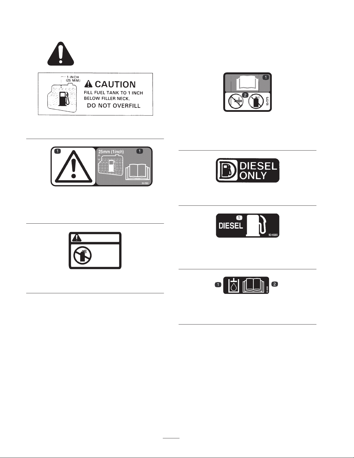
Safety and Instruction Decals
Safety decals and instructions are easily visible to the operator and are located near any area
of potential danger. Replace any decal that is damaged or lost.
27-7310
(Models 30626 & 30627)
93-7822
(Models 30630 & 30631)
1. Caution—fill fuel tank to 1 in. (25 mm) below filler neck. Read
the operator’s manual for further instructions.
CA UTION
DO NOT USE
STARTING
FLUID
83-9150
83-9150
(Models 30626 & 30627)
93-7275
(Models 30630 & 30631)
1. Read the operator’s manual for further instructions.
2. Do not use starting fluid.
52-1321
(Models 30626 & 30627)
93-6680
(Models 30630 & 30631)
1. Diesel fuel
93-6686
1. Hydraulic oil 2. Read the
8
Manual.
Operator’s
Page 9
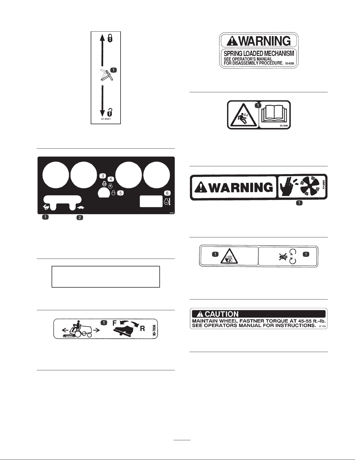
82-8940
1. Locks and unlocks the steering column
105-0056
1. Fast
2. Slow
3. Engine stop
4. Engine run
5. Engine start
6. Temperature
55-4300
(Models 30626 & 30627)
93-6696
(Models 30630 & 30631)
1. Warning—spring loaded mechanism. Read the operator’s
manual for further instructions.
77–3100
(Models 30626 & 30627)
1. Fan blades can cause injury—stay away from moving parts.
TRACTION PEDAL
27-7320
(Models 30626 & 30627)
93-7836
1. To move the traction unit forward or backward, depress the
traction pedal.
93-7272
(Model 30630 & 30631)
1. Fan blades can cause injury—stay away from moving parts.
67-1720
(Models 30626 & 30627)
9
Page 10
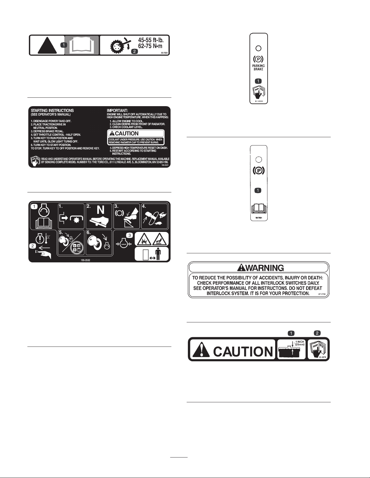
93-7830
(Models 30630 & 30631)
1. Caution—read the operator’s manual for further instructions.
2. Wheel torque specifications
105-2531
(Models 30626 & 30627)
82-8930
(Model 30626 & 30627)
1. Read the operator’s manual for further instructions.
93-7831
1. Parking brake—read the operator’s manual for further
instructions.
105-2532
(Models 30630 &30631)
1. To start the engine, disengage the Power Take Off, place the
traction drive in neutral, depress the brake pedal, set the
throttle control half open, turn the ignition key to the run
position. When the glow light turns off, turn the key to the start
position. Read the operator’s manual for further instructions.
2. Warning—when engine temperature is too high, engine will
shut off. Depress high temperature reset before restarting
engine.
3. Warning—coolant is under pressure and could cause burns.
Keep a safe distance away.
67–1710
(Model s 30626 & 30627)
82-8970
(Models 30626 & 30627)
1. Fill coolant to within 1 in. (25 mm) of the top of the tank.
2. Read the operator’s manual for further instructions.
10
Page 11
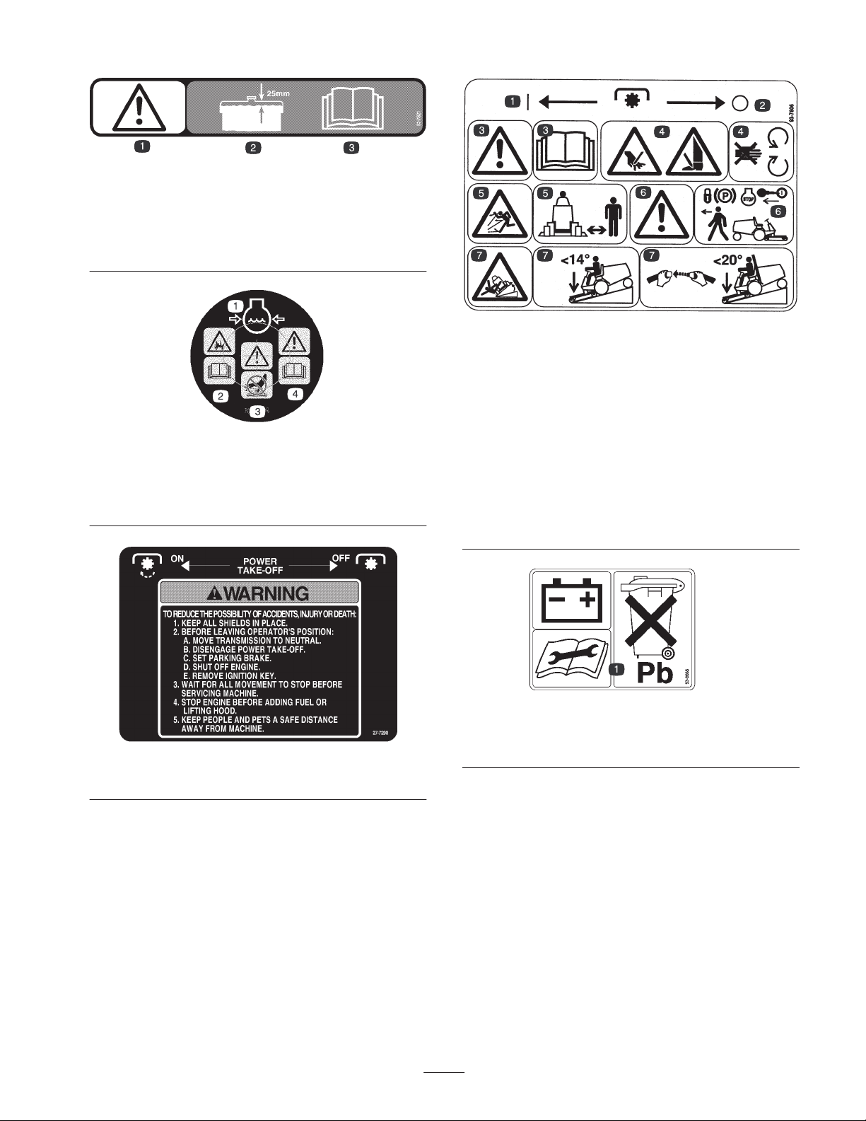
93–7821
(Models 30630 & 30631)
1. Caution
2. Fill coolant to within 1 in. (25 mm) of the top of the tank.
3. Read the operator’s manual for further instructions.
106-5976
1. Engine coolant under
pressure
2. Explosion hazard—read
Operator’s Manual.
the
3. Warning—do not touch
the hot surface.
4. Warning—read the
Operator’s Manual.
93-7806
(Models 30630 & 30631)
1. PTO on
2. PTO off
3. Warning—read the operator’s manual.
4. Cutting hazard to hands or feet—stay away from rotating
blades and moving parts.
5. Throw object hazard—keep bystanders away.
6. Warning—set the parking brake, stop the engine, and remove
the key before leaving the operator’s position.
7. Tipping hazard—when driving down slopes less that 14
degrees, lower the cutting unit to the ground. When driving
down slopes less than 20 degrees, use the ROPS, fasten the
seat belt, and lower the cutting unit to the ground.
27-7290
(Models 30626 & 30627)
93-6668
(Models 30630 & 30631)
1. The battery contains lead. Do not throw it in the garbage.
11
Page 12
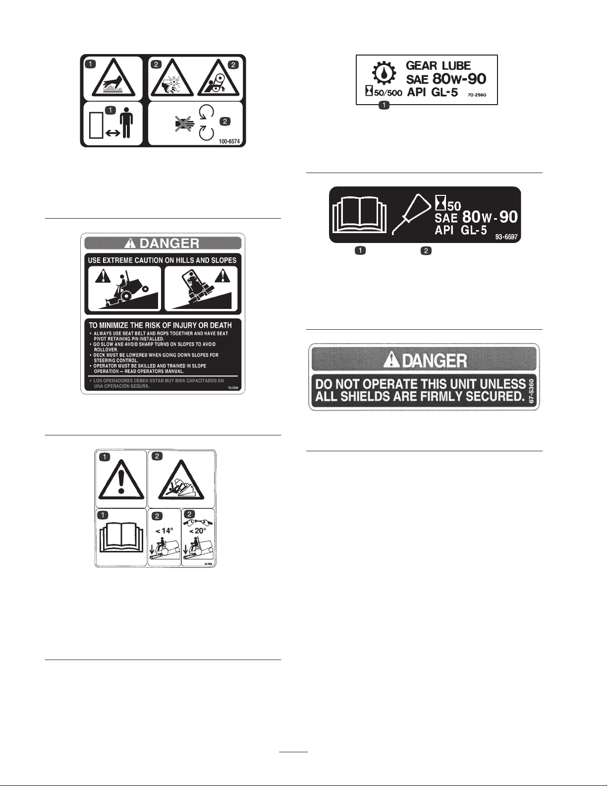
(Models 30630 & 30631)
1. Hot surface hazard—stay
away.
(Model 30627)
100-6574
2. Cutting/dismemberment
72-3700
70–2560
(Model 30627)
1. Change the rear axle lubricant initially after first 50 operating
hours, thereafter every 500 hours
hazard—stay away from
moving parts.
93–6697
(Model 30631)
1. Read operator manual
2. Change the rear axle lubricant initially after first 50 operating
hours, thereafter every 500 hours
67–5360
(Models 30626 & 30627)
93-7839
(Model 30631)
1. Danger—read the operator’s manual.
2. Tipping hazard—when driving down slopes less that 14
degrees, lower the cutting unit to the ground. When driving
down slopes less than 20 degrees, use the ROPS, fasten the
seat belt, and lower the cutting unit to the ground.
12
Page 13
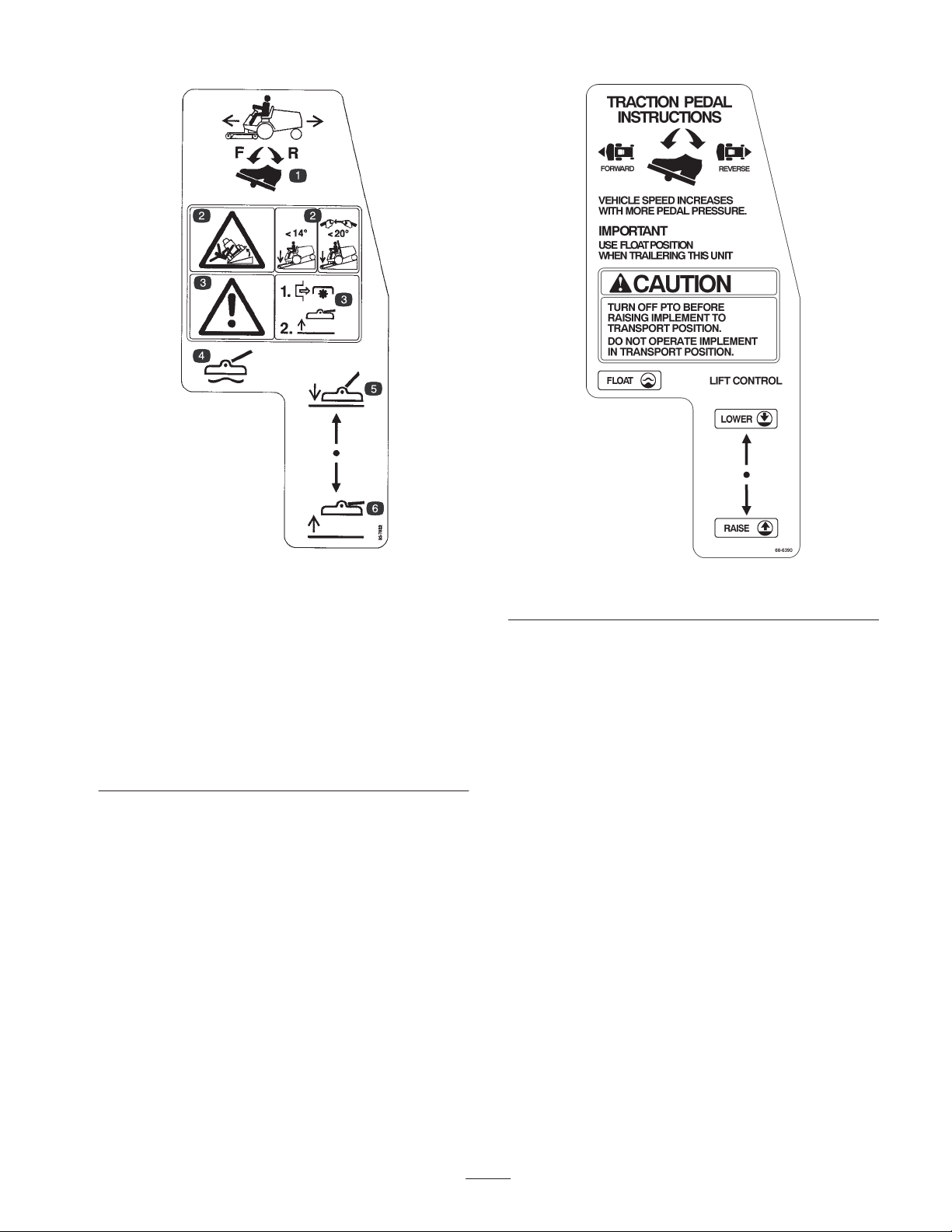
93-7832
(Models 30630 & 30631)
1. To move the traction unit forward or backward, depress the
traction pedal.
2. Tipping hazard—when driving down slopes less that 14
degrees, lower the cutting unit to the ground. When driving
down slopes less than 20 degrees, use the ROPS, fasten the
seat belt, and lower the cutting unit to the ground.
3. Warning—disengage the Power Take Off before raising the
cutting unit.
4. Float cutting unit
5. Lower cutting unit
6. Raise cutting unit
66-6390
(Models 30626 & 30627)
13
Page 14

Specifications
Note: Specifications and design subject to change without notice.
General Specifications
Engine
Air Cleaner Heavy duty, remote mounted
Muffler
Cooling System
Electrical
Fuel System
Front Axle
Rear Axle
(Models 30627 & 30631)
Transmission
Kubota, three cylinder, 4 cycle liquid cooled diesel engine. 26 hp @ 3000. Engine
governed to 3200–3250 rpm high idle, no load.
Volume equal to approximately five times engine displacement for excellent
silencing.
Radiator has tube and fin construction with hydraulic oil cooler in lower tank.
Capacity of cooling system is approximately 6 quarts (5.7 l) of a 50% mixture of
permanent, ethylene glycol anti-freeze and water.
12 volt battery has 630 amp., cold cranking performance at 0° F (–18° C). Fuse
block located under the control panel. Starter relay interlock circuit for maximum
current hold–in of starter solenoid in low voltage conditions
Fuel tank capacity is approximately 6-1/2 gal. (25 l). 12 volt, electric fuel pump .
Fuel filter/water separator with replaceable cartridge is mounted on frame.
The heavy duty Dana GT 20 axle has reduction of 20:9:1. Axle has automotive type
differential, bevel gear pinion and ring gear with spur gear reduction from
transmission. All axle components are mounted in tapered roller bearings.
The rear axle is mechanically driven from the front axle by a universal shaft. Axle
has a bidirectional – overrunning clutch in rear driveshaft. When lubricating rear
axle, use SAE 80W-90 gear lube, API GL-5. Lubricant capacity is approximately
2.2 qt. (2.1 L).
The in-line hydrostatic transmission is mounted directly to the front axle and is
driven by flexible drive couplings. Operating pressure is 500 to 3000 psi (3447 to
20685 kPa) and normal charge pressure is 70 to 150 psi (453 to 1034 kPa).
Implement relief valve setting is 700 to 900 psi (4826 to 6205 kPa). Displacement is
0.913 cubic inch (15 cm
foot-actuated pedal. Front axle is the hydraulic fluid reservoir, and its capacity is 5
quarts (4.7 l). The 25 micron hydraulic filter is a screw on replaceable type. For
replacement filters, order Toro Part No. 23-9740.
3
) per revolution, and transmission is controlled by
Ground Speed Speed is infinitely variable from 0 to 9.5 MPH (0 to 15 km/h) forward or reverse.
Two rear tires are 18 x 6.50-8, 4-ply, extra traction tread, on demountable, drop
Tires
Brakes
Steering
Main Frame
center wheels. The two from tires are 23 x 8.50-12, extra traction tread, 4-ply rating,
on demountable, drop center wheels. Recommended air pressure for both the front
and rear tires is 21 psi (145 kPa).
Brakes controlled by 3 pedals. Two are for steering assist. Are individually
controlled by left foot. Third pedal operates both brakes; is controlled by either foot.
Parking brake latch provided for third pedal. Pedals are connected to brakes by
multi-stranded cable and conduit.
The 13 inch (33 cm) steering wheel is mounted on a steering valve consisting of a
control valve and metering section which regulates pressure and meters flow to the
steering cylinder. Minimum turning radius is 18 in. from center of turn to closest side
of drive wheel; however, zero turning radius results when individual wheel brakes
are used. Steering wheel adjustable fore and aft for operator comfort.
Frame is welded, formed 11 ga. steel, reinforced with square and rectangular
tubing.
14
Page 15

General Specifications (continued)
PTO switch—shuts engine off when PTO is engaged with no operator in seat.
Traction switch—shuts engine off when traction pedal is engaged with no operator
Interlock Switches
Instrument Panel and
Control
PTO Drive
in seat. Seat switch—shuts engine off if operator leaves seat without disengaging
PTO and/or traction pedal. Engine will not start if PTO or traction pedal is engaged.
Brake switch–shuts engine off when PTO or traction pedal is engaged with parking
brake set.
Hour meter, fuel gauge, ignition switch, oil pressure warning light, charge indicator,
engine coolant temperature warning light, temperature gauge, temperature override
switch, glow plug indicator light and throttle control are on instrument panel. Hand
operated PTO lever is located to right of the seat. Traction pedal for traction
operation at right of steering column.
Shaft is driven by a tight-slack double “A” section, torque team V-belt directly from
output shaft of engine. Shaft is clutched by pivoting the shaft support with a spring
loaded, over center, hand operated lever. PTO speed 1810 RPM @ 3200 RPM
engine speed. Connection to implement is with high quality, needle bearing
universal joint with slip joint.
Implement Lift
Cutting unit or implement is lifted by hydraulic cylinder that has 2-1/2 in. (64 mm)
bore and 3-1/4 in. (82 mm) stroke.
Dimensions and Weights
(approx.)
Width (measured from
outside of front tires)
Length 91 in. (231 cm)
Height 50 in. (127 cm)
Height w/ROPS 78.5 in. (199 cm)
Dry Weight – 2 Wheel
Drive w cutter deck
Dry Weight – 4 Wheel
Drive
Wheel Base 49 in. (124 cm)
46 in. (117 cm)
1650 lb. (743 kg)
2065 lb. (929 kg)
15
Page 16

Optional Equipment
72” Side Discharge Cutting Unit Model No. 30722
Model No.
30722TE
72” Rear Discharge Cutting Unit Model No. 30710
Model No.
30710TE
72” Flex Deck Cutting Unit Model No. 30799
Guardian 72″ Recycler Cutting Unit Model No. 30716
Cushion Seat Model No. 30623
Deluxe Suspension Seat Kit (requires
Model No. 30628)
Seat Adapter Kit Model No. 30628
Armrest Kit
(for seat models 30623 & 30625)
Speed Control Kit Model No. 30677
48 in. V-Plow
(requires Model No. 30757)
V-Plow Mounting Kit
(w/o tire chains)
Debris Blower Model No. 30855
Spark Arrestor Screen Part No. 75–6880
Rotary Broom Model No. 30743
Quick Attach Receiver Kit
(for traction unit)
Model No. 30625
Model No. 30707
Model No. 30750
Model No. 30757
Model No. 30711
Quick Attach (for Guardian 72″
Recycler Cutting Unit, Model No.
30716)
Quick Attach (for 72” Side
Discharge Cutting Unit, Model No.
30722, 72” Rear Discharge Cutting
Unit, Model No. 30710 and Rotary
Broom, Model No. 30743)
Tire Chains (front) (set of 2) Part No. 11-0390
Tire Chains (rear) (set of 2)
(Models 30627 & 30631 only)
Wheel Weight Kit (set of 2) Part No. 11-0440
Rear Weight Kit (set of 2) Part No. 24-5780
Rear Weight Kit (set of 1) Part No. 24-5790
4-Ply Wide Tire w/Rim, 23 x 10.5 x
12 (2 required; will not fit with 72”
Rear Discharge Cutting Unit, Model
No. 30710)
6–Ply Wide Tire w/ Rim
23 x 10.5 x 12 (2 required; will not
fit with 72” Rear Discharge Cutting
Unit, Model No. 30710)
Jack Pad Kit Part No.
Model No. 30729
Model No. 30719
Part No. 76–1840
Part No. 62-7020
Part No. 69-9870
106–4386
16
Page 17

Setup
Note: Determine the left and right sides of the machine from the normal operating position.
Loose Parts
Note: Use the chart below to verify that all parts have been shipped.
Description Qty. Use
Screw, M10 x 30 mm
Washer
Tie rod 1
Bumper 1
Flange head screw, 5/16 x 1 in.
Locknut 5/16 in.
Rear wheel 2 Mounting rear steering wheels (Metric nuts)
Front wheel 2 Mounting front wheels (English nuts)
Steering wheel
Foam seal
Nut
Screw
Cap
Manual tube (shipped in tool box)
R-clamp
Seat belt
Bolt, 7/16 x 1 in.
Lock washer, 7/16 in.
4
4
1
1
1
1
1
1
1
1
2
1
2
2
Mounting steering cylinder to rear axle.
(Models 30627 & 30631 only)
Mount to steering arms.
(Models 30627 & 30631 only)
Mount to axle support.
(Models 30627 & 30631 only)
Secure steering hoses to bumper.
(Models 30627 & 30631 only)
Installing the steering wheel
Holding the operator’s manual. Install on right
underside of seat.
Installing the seat belts
(Models 30627 & 30631 only)
Roll Bar (ROPS)
Bolt, 3/4 x 3-1/2 in.
Lock washer, 3/4 in.
Nut, 3/4 in.
Right-hand ball joint (shipped in tool box) 1
Hydraulic oil filter 1 Change after 10 hours
Parts catalog 1
Operator’s Manual (traction unit) Model 30627 2 Read before operating the machine.
Operator’s Manual (traction unit) Model 30631 1 Read before operating the machine.
Operator Video 1 Watch before operating the machine.
Registration card 1 Fill out and return to Toro.
1
4
4
4
Installing the roll bar
(Models 30627 & 30631 only)
Install ball joint (implement installation) and
connect lift cylinder
17
Page 18

Note: Some models may have already been set–up at
factory.
Installing the Steering Cylinder
(Models 30627 & 30631 only)
1. Remove screw and R-clamp securing steering cylinder
to packaging. Retain R-clamp for future installation.
2. Mount cylinder support bracket to rear of axle with 4
screws (M10 x 30) screws and washers (Fig. 2). Apply
Loctite 242, or equivalent, and torque screws to 34-42
ft.-lb. (46–56 N⋅m).
2
1
Figure 2
1. Cylinder support bracket 2. Steering arm
3. Remove jam nuts from ball joint end of steering
cylinder. Insert ball joint end into center hole of axle
steering arm. Insert the ball joint from the top of the
steering arm.
4. Secure ball joint end to steering arm with a jam nut
(Fig. 2) and torque it to 70–90 ft.-lb. (94–122 N⋅m).
Install a second jam nut and torque it to 70–90 ft.-lb.
(94–122 N⋅m).
Installing the Tie Rod
(Models 30627 & 30631 only)
1. Remove jam nuts from ball joint ends of tie rod. Insert
ball joint ends into rear hole of each axle steering arm.
Insert ball joints from bottom of each steering arm
(Fig. 3).
2. Secure ball joint ends to steering arms with a jam nut
and torque it to 40–60 ft.-lb. (54–81 N⋅m). Install a
second jam nut and torque it to 40–60 ft.-lb.
(54–81 N⋅m).
1
Figure 3
1. Tie rod
Installing the Rear Bumper
(Models 30627 & 30631 only)
1. Remove 2 capscrews (1/2 x 3/4 in.), lock washers, and
flat washers securing rear weight to axle support
(Fig. 4).
3
1
Figure 4
1. Rear weight
2. Axle support
2. Using capscrews, lock washers and flat washers
previously removed, mount bumper and rear weight to
axle support.
3. Using R-clamp removed in step 1, secure steering hoses
to top of bumper with a flange head screw (5/16 x 1 in.)
and locknut supplied, in loose parts.
2
3. Bumper
4. R-clamp
4
Installing the Front and Rear
Wheels
1. Remove and discard fasteners securing wheels to
packaging.
2. Remove wheel nuts from studs on axles.
Note: Front wheel nuts are English and rear wheel nuts are
metric.
3. Mount wheels and torque mounting nuts to 45-55 ft.-lb.
(61-75 N⋅m).
18
Page 19

Installing the Steering Wheel
Installing the Seat
1. Move rear wheels so they point straight ahead.
2. Remove jam nut from steering shaft. Slide foam seal
and steering wheel onto steering shaft (Fig. 5).
4
3
2
1
5
Figure 5
1. Steering wheel
2. Jam nut
3. Cap
4. Screw
5. Foam seal
3. Secure steering wheel to shaft with jam nut and tighten
it to 10–15 ft.-lb.
4. Install cap to steering wheel with screw (Fig. 5).
Removing the Battery from the
Chassis
1. Release the two latches holding instrument cover in
place. Carefully remove instrument cover to expose the
battery.
The machine is shipped without the seat assembly. Either
optional Seat Kit, Model No. 30623 or 30625 must be
installed.
Seat Kit, Model No. 30623, Standard Seat
1. Loosely secure (2) R-clamps to right side of seat bottom
with 2 capscrews and flat washers supplied in kit
(Fig. 7). Install manual tube into R-clamps and tighten
capscrews (Fig. 7).
2
3
1
4
Figure 7
1. R-clamps
2. Seat support
2. Mount seat pivot bracket to frame with 2 flange screws
supplied in kit (Fig. 8)
3. Manual tube
4. Cap
2. Remove two wing nuts and hold down strap that secures
battery (Fig. 6). Lift battery out of chassis. Keep wing
nuts and hold down strap in safe place for later use.
1
2
1
4
3
Figure 6
1. Wing nuts
2. Hold down strap
3. Positive terminal
4. Negative terminal
1
Figure 8
1. Seat pivot bracket
3. Mount seat and seat support to seat pivot bracket with
pivot shaft and roll pin (Fig. 9).
19
Page 20

7. Slide seat completely forward and backward to ensure
proper operation and that seat switch wires and
connectors are not pinched or do no contact any moving
parts.
1
2
Figure 9
1. Pivot shaft 2. Roll pin
4. Hold seat up with seat support rod (Fig. 10).
5. Plug wire harness connector into seat switch connector
on bottom of seat.
1
Figure 10
1. Seat support rod
Seat Kit, Model No. 30625, Deluxe Seat
with Model No. 30628 Seat Adapter Kit
1. Mount seat suspension assembly to 4 capscrews on seat
bottom and secure with 4 lock washers, flat washers,
and nuts (Fig. 12).
6
1
4
2
3
5
Figure 12
1. Seat suspension
assembly
2. R-clamps
3. Lock washer, flat washer,
and nut
4. Manual tube
5. Cap
6. Seat support
6. Disengage seat support rod and pivot downward. Pivot
seat down and push lynch pin through seat latch stud.
Flip wire end of pin over latch stud (Fig. 11).
1
Figure 11
1. Lynch pin
2. Loosely secure 2 R-clamps to right side of seat bottom
with 2 capscrews and flat washers supplied in kit
(Fig. 12). Install manual tube into R-clamps and tighten
capscrews (Fig. 12).
3. Mount seat support over four threaded studs at the
bottom of seat suspension assembly and secure in place
with flangenuts (Fig. 12).
4. Mount seat pivot bracket to frame with (2) flange
screws supplied in kit (Fig. 8)
5. Mount seat and seat support to seat pivot bracket with
pivot shaft and roll pin (Fig. 9).
6. Hold seat up with seat support rod (Fig. 10).
7. Route seat switch harness through holes in seat support
and seat suspension (Fig. 13). Plug wire harness
connector into seat switch connector on bottom of seat.
20
Page 21

1
Figure 13
1. Seat switch wire harness
8. Disengage seat support rod and pivot downward. Pivot
seat down and push lynch pin through seat latch stud.
Flip wire end of pin over latch stud (Fig. 11).
9. Slide seat completely forward and backward to ensure
proper operation and that seat switch wires and
connectors are not pinched or do no contact any moving
parts.
Installing the Seat Belt
(
Models 30627 & 30631 only)
Install seat belt to holes in back of seat with 2 bolts
(7/16 x 1 in.) and lock washers (Fig. 14). Tighten securely.
1
1
Figure 15
1. Roll bar
Pushing the Traction Unit Off
of the Pallet
1. Reach in and rotate bypass valve on transmission
(Fig. 16) counterclockwise 1/2 to 1 turn. Opening the
valve opens an internal passage in the pump, thereby
bypassing transmission oil. Because fluid is bypassed,
the machine can be pushed without damaging the
transmission.
1
2
Figure 14
1. Seat belt 2. Bolt and lock washer
Installing the Roll Bar
(Models 30627 & 30631 only)
1. Lower roll bar onto frame, aligning mounting holes as
shown in Figure 15.
2. Secure roll bar to frame with 4 bolts (3/4 x 3-1/2 in.),
lock washers, and nuts (Fig. 15). Tighten securely.
Figure 16
1. Bypass valve
2. Lift machine over shipping braces and push machine off
pallet.
3. Close bypass valve by rotating it clockwise until it is
securely seated. Do not exceed 5 to 8 ft.-lb. (7 to
11 N⋅m). Do not start engine when valve is open.
21
Page 22

Activating and Charging the
Battery
2. Slide the red, positive battery cable (Fig. 6) onto
positive battery post and tighten nut securely.
1. If battery is not filled with electrolyte or charged, bulk
electrolyte with 1.280 specific gravity @ 77° F
(25°C) must be purchased from a local battery supply
outlet.
Danger
Battery electrolyte contains sulfuric acid which is a
deadly poison and causes severe burns.
• Do not drink electrolyte and avoid contact with
skin, eyes or clothing. Wear safety glasses to
shield your eyes and rubber gloves to protect
your hands.
• Fill the battery where clean water is always
available for flushing the skin.
2. Remove filler caps from battery and slowly fill each
cell until electrolyte is just above the plates. Install filler
caps.
3. Connect a 3 to 4 amp. battery charger to the battery
posts. Charge the battery at a rate of 3 to 4 amperes for
4 to 8 hours.
4. When battery is fully charged, disconnect charger from
electrical outlet and battery posts.
5. Remove filler caps and slowly add electrolyte to each
cell until level is up to fill ring. Install fill caps.
Warning
Incorrect battery cable routing could damage the
machine and cables causing sparks. Sparks can
cause the battery gasses to explode, resulting in
personal injury.
• Always disconnect the negative (black) battery
cable before disconnecting the positive (red)
cable.
• Always connect the positive (red) battery cable
before connecting the negative (black) cable.
3. Slide the black, negative battery cable (Fig. 6) onto
negative battery post and tighten nut securely.
4. Coat both battery connections with either Grafo 112X
(skin-over) grease, Toro Part No. 505-47, petroleum
jelly or light grease to prevent corrosion and slide
rubber boot over positive terminal
5. Install the instrument cover and lock the two latches.
(Fig. 6).
Installing the Ball Joint and
Connecting the Lift Cylinder
Note: Ball joints are not required for all implements; refer
to implement operator’s manual for requirements.
1. Thread jam nut fully onto right-hand ball joint.
Installing the Battery in the
Chassis
Warning
Battery terminals or metal tools could short
against metal machine components causing sparks.
Sparks can cause the battery gasses to explode,
resulting in personal injury.
• When removing or installing the battery, do not
allow the battery terminals to touch any metal
parts of the machine.
• Do not allow metal tools to short between the
battery terminals and metal parts of the
machine.
1. Install battery and secure with hold down strap and
wing nuts (Fig. 6). Remove tape over ends of each
cable.
2. Screw ball joint into right hand push arm until center of
ball joint is 2-3/8 in. (60 mm) away from front of push
arm (Fig. 17). Do not tighten jam nut.
2
1
4
4
Figure 17
1. Jam nut
2. Ball joint mount
3. 2-3/8 in. (60 mm)
4. Right-hand push arm
22
Page 23

Warning
5. Remove spring pin from cylinder pin and slide cylinder
pin out of cylinder.
Sudden release of the spring-loaded push arms
could cause injury.
Acquire the help of another person to help push
the arms down during installation of the ball joints
or other implements.
3. Have a helper push down on the left push arm. Then
insert a 2 x 4 in. (51 x 102 mm) block of wood between
the frame and top of the push arm (Fig. 18). Screw ball
joint into left hand push arm until center of ball joint is
2-3/8 in. (60 mm) away from front of push arm
(Fig. 18). Do not tighten jam nut.
1
5
3
2
6. Raise front of lift arm until hole in movable end of
cylinder lines up with holes in lift arm brackets. Use
caution as lift arm is spring-loaded. Hold parts together
with cylinder pin, spring pin, and cotter pin. Cotter pin
must be to the outside.
7. Install implement; refer to implement Operator’s
Manual for proper installation procedures.
Checking the Tire Pressure
The tires are over-inflated for shipping. Therefore, release
some of the air to reduce the pressure. Correct air pressure
in the front and rear tires is 21 psi (145 kPa).
Checking the Torque of the
Front Wheel Nuts
Warning
Failure to maintain proper torque of the front
wheel nuts could result in failure, loss of wheel, or
personal injury.
4
Figure 18
1. Jam nut
2. 2 x 4 in. (51 x 102 mm)
block
4. Carefully remove 2 x 4 in. (51 x 102 mm) block of
wood from between frame and push arm.
3. Left-hand push arm
4. Ball joint mount
5. 2-3/8 in. (60 mm)
Torque the front wheel nuts to 45–55 ft.-lb.
(61–75 Nm) after 1–4 hours of operation and
again after 10 hours of operation. Torque every
250 hours thereafter.
Greasing the Traction Unit
Before the machine is operated, it must be greased to assure
proper operating characteristics; refer to Lubrication
Maintenance. Failure to grease the machine will result in
premature failure of critical parts.
Note: After setup has been completed, remove protective
edging (used for shipping) from fenders.
23
Page 24

Install Rear Weight
To comply with CEN standard EN 836:1997, ISO standard 5395:1990 and ANSI/OPEI B71.4–1999 Standard, rear weight
must be added to rear of traction unit. Use chart below to determine weight requirements. Order parts from your local
Authorized Toro Distributor.
Note: A rear weight kit, part no. 24–5780 is supplied with Model No. 30630.
Two Wheel Drive
Cutting Unit
Description
72″ Side Discharge
(Model No. 30722)
72″ Rear Discharge
(Model No. 30710)
Guardian 72″
Recycler
(Model No. 30716)
72” Flex Deck
(Model 30799)
Four Wheel Drive
Cutting Unit
Description
72” Flex Deck
(Model 30799)
Rear Weight
Required
70 lb. 24–5780 Rear Weight Kit
70 lb. 24–5780 Rear Weight Kit
70 lb. 24–5780 Rear Weight Kit
210 lb. 24–5780 Rear Weight Kit
Rear Weight
Required
70 lb. 24–5780 Rear Weight Kit
Weight Part
Number
Weight Part
Number
Weight Description Qty.
(two 35 lb. weights and mounting hardware)
(two 35 lb. weights and mounting hardware)
(two 35 lb. weights and mounting hardware)
(two 35 lb. weights and mounting hardware)
Weight Description Qty.
(two 35 lb. weights and mounting hardware)
1
1
1
3
1
24
Page 25

Before Operating
Hood Prop
(Models 30626 & 30627 only)
1. Position the machine on a level surface.
2. Disengage hood latch and open the hood.
3. Slide bottom of hood prop (Fig. 19) out of retaining
bracket. Lower hood prop, pivot upward, then
downward to prop up hood.
1
Figure 19
1. Hood prop
1
Figure 20
1. Dipstick
3. If oil is below FULL mark, remove fill cap and add
SAE 10W–30 CD, CE, CF, CF–4 or CG–4
classification oil until level reaches FULL mark on
dipstick. DO NOT OVERFILL.
1
Check Engine Oil
The engine is shipped with 3.25 qt (3.1 l) of oil in the
crankcase; however, level of oil must be checked before
and after the engine is first started.
1. Park machine on a level surface, stop engine and
remove key from ignition switch. Open hood and install
hood prop.
2. Remove dipstick (Fig. 20), wipe clean and reinstall
dipstick. Remove dipstick and check oil level. Oil level
should be up to FULL mark on dipstick
Figure 21
1. Oil fill
4. Install oil fill cap and close hood.
25
Page 26

Filling the Fuel Tank
Danger
Under certain conditions, diesel fuel and fuel
vapors are highly flammable and explosive. A fire
or explosion from fuel can burn you and others
and can cause property damage.
• Use a funnel and fill the fuel tank outdoors, in
an open area, when the engine is off and is cold.
Wipe up any fuel that spills.
• Do not fill the fuel tank completely full. Add fuel
to the fuel tank until the level is 1 in. (25 mm)
below the bottom of the filler neck. This empty
space in the tank allows the fuel to expand.
• Never smoke when handling fuel, and stay away
from an open flame or where fuel fumes may be
ignited by a spark.
• Store fuel in a clean, safety-approved container
and keep the cap in place.
1. Tip seat forward and prop it with the support rod so it
cannot fall accidentally. Using a clean rag, clean area
around fuel tank cap (Fig. 22).
2. Remove cap from the fuel tank and fill the 6-1/2 gallon
(25 l) tank to within 1 in. (25 mm) from the top with
diesel fuel. Install fuel tank cap tightly after filling tank.
The cooling system is filled with a 50 / 50 solution of water
and permanent ethylene glycol anti–freeze. Check level of
coolant in expansion tank at beginning of each day before
starting the engine. Capacity of cooling system is 6 quarts
(5.6 l).
Caution
• If engine has been running, pressurized hot
coolant can escape when radiator cap is
removed and cause burns.
1. Check level of coolant in expansion tank. Coolant level
should be between the marks on side of tank.
1
Figure 23
1. Expansion tank
1
Figure 22
1. Fuel tank cap
Check Cooling System
Clean debris off screen and radiator/oil cooler daily, more
often if conditions are extremely dusty and dirty.
2. If coolant level is low, remove expansion tank cap and
replenish the system. DO NOT OVERFILL.
3. Install expansion tank cap.
Checking the Hydraulic System
Fluid
The front axle housing acts as the reservoir for the system.
The transmission and axle housing are shipped from the
factory with approximately 5 quarts (4.7 l) of high quality
hydraulic fluid. However, check fluid level before engine is
first started and daily thereafter.
Note: Fluid to operate the power steering is supplied by the
hydraulic system transmission charge pump. Cold weather
start-up may result in “stiff” operation of the steering until
the hydraulic system has warmed up.
The following list is not assumed to be all–inclusive.
Hydraulic fluids produced by other manufacturers may be
used if they can cross reference to find an equivalent to the
products listed. Toro will not assume responsibility for
26
Page 27

damage caused by improper substitutions, so use only
products from reputable manufacturers who will stand
behind their recommendation.
Universal Tractor Hydraulic Fluid
Mobil Mobil Fluid 424
Amoco 1000 Fluid
Chevron Tractor Hydraulic Fluid
Conoco Power–Tran 3
Exxon Torque Fluid
Pennzoil Hydra–Tranz
Shell Donax TD
T exaco TDH
Note: Many hydraulic fluids are almost colorless, making it
difficult to spot leaks. A red dye additive for the hydraulic
system oil is available in 2/3 oz. (20 ml) bottles. One bottle
is sufficient for 4–6 gal (15–22 1) of hydraulic oil. Order
part no.44–2500 from your authorized Toro distributor.
1. Position machine on a level surface, raise the
implement, and stop the engine.
2. Unscrew dipstick cap (Fig. 24) from the filler neck and
wipe it with a clean rag. Screw dipstick cap finger tight
onto filler neck. Unscrew the dipstick and check level
of fluid. If level is not within 1/2 in. (13 mm) from the
groove in the dipstick (Fig. 24), add enough fluid to
raise level to groove mark. Do not overfill by more
than 1/2 in. (13 mm) above groove.
Important When adding oil to the hydraulic system,
use a funnel with a fine wire screen—200 mesh—and
ensure funnel and oil are immaculately clean. This
procedure prevents accidental contamination of the
hydraulic system.
Checking the Rear Axle
The rear axle has three separate reservoirs which use SAE
80W-90 wt. gear lube. Although the axle is shipped with
lubricant from the factory, check the level before operating
the machine.
1. Position the machine on a level surface.
2. Remove check plugs from axle and make sure lubricant
is up to bottom of each hole. If level is low, remove fill
plugs and add enough lubricant to bring the level up to
the bottom of the check plug holes (Fig. 25).
3
1
1. Check plug
2. Fill/check plug (one on
each end of axle)
Figure 25
3. Fill plug
2
Check Bidirectional Clutch
Lubricant
(Models 30627 & 30631 only)
1. Position the machine on a level surface.
1
2
Figure 24
1. Dipstick cap 2. Groove
3. Screw dipstick filler cap finger–tight onto filler neck. It
is not necessary to tighten cap with a wrench.
4. Lower the implement.
2. Rotate clutch (Fig. 26) so check plug (shown in 12
o’clock position) is positioned at 4 o’clock.
2
1
Figure 26
1. Bidirectional clutch 2. Check plug
27
Page 28

3. Remove check plug. Fluid level should be up to hole in
clutch. If fluid level is low, add Mobil Fluid 424. Clutch
should be approximately 1/3 full.
4. Install check plug.
Note: Do not use engine oil (i.e. 10W30) in bidirectional
clutch. Anti-wear and extreme pressure additives will cause
undesirable clutch performance.
Operation
Tilt Steering Control
The tilt steering control is a lever on right side of steering
column (Fig. 27). Pull lever rearward to adjust steering
wheel to desired fore or aft operating position and push
lever forward to lock adjustment.
Caution
Do not leave lever in unlocked position.
Note: Determine the left and right sides of the machine
from the normal operating position.
Controls
Traction Pedal
The traction pedal (Fig. 27) has two functions; one is to
make the machine move forward, the other is to make it
move backward. Using the heel and toe of the right foot,
depress top of pedal to move forward and bottom of pedal
to move backward. Ground speed is proportionate to how
far pedal is depressed. For maximum ground speed with no
load, traction pedal must be fully depressed while throttle is
in FAST position. Maximum speed forward is
approximately 9.5 mph (15 km/h). To get maximum power
under heavy load or when ascending a hill, have throttle in
FAST position while depressing traction pedal slightly to
keep engine rpm high. When engine rpm begins to
decrease, release traction pedal slightly to allow engine rpm
to increase.
Caution
When foot is removed from the traction pedal,
machine should stop; it must not creep in either
direction. If machine does creep, do not operate
until neutral assembly has been repaired and
adjusted; refer to Adjusting Traction Drive for
Neutral.
Turn Pedals
Brake Pedal
Whenever the engine is shut off, the parking brake (Fig. 27)
must be engaged to prevent accidental movement of the
machine.
The hydrostatic transmission will not, at any time, act as a
parking brake for the machine. To engage parking brake,
push down fully on brake pedal and pull parking brake
knob out; then release the pedal. To release parking brake,
depress brake pedal until parking brake knob retracts. To
stop quickly, remove right foot from traction pedal and
depress the brake pedal. To permit straight stops, brake
cables must be evenly adjusted.
54
1
3
2
Figure 27
1. Traction pedal
2. Turn pedals
3. Brake pedal
4. Parking brake knob
5. Tilt steering control
The left and right turn pedals (Fig. 27) are connected to the
left and right front wheel brakes since both brakes work
independently of each other. The brakes can be used to turn
sharply or to increase traction if one wheel tends to slip
while operating on a hillside. However, wet grass or soft
turf could be damaged when brakes are used to turn.
Lift Lever
The hydraulic lift lever (Fig. 28) has three positions:
FLOAT, TRANSPORT, and RAISE. To lower implement to
the ground, move lift lever forward into detent, which is the
FLOAT position. The FLOAT position is used for operation
and also when machine is not in operation. To raise
implement, pull lift lever backward to the RAISE position.
After implement is raised, allow lift lever to move to the
28
Page 29

TRANSPORT position. Normally, implement should be
raised when driving from one work area to another, except
when descending steep slopes.
Charge Indicator
Illuminates when system charging circuit malfunctions
(Fig. 29).
Caution
The exposed, rotating blades of the cutting unit or
other implements are hazardous.
Never raise a cutting unit or implement while the
blades or other components are rotating.
1
Figure 28
1. Lift lever
PTO Lever
The PTO lever (Fig. 29) has two positions: ON (engage)
and OFF (disengage). Slowly push PTO lever fully forward
to ON position to start the implement or cutting unit blades.
Slowly, pull lever backward to OFF position to stop
implement operation. The only time PTO lever should be in
the ON position is when implement or cutting unit is down
in operating position.
Engine Coolant Temperature Warning
Light
The light illuminates and engine shuts down when coolant
reaches a excessively high temperature (Fig. 29).
2
1
3
11
12
4
10
5
7
6
8
9
Figure 29
1. PTO lever
2. Fuel gauge
3. Hour meter
4. Oil pressure indicator
5. Engine temperature
6. Glow plug indicator
7. Charge indicator
8. Temperature gauge
9. Temperature override
switch
10. Key switch
11. Throttle control
12. Battery cover
Temperature Gauge
Fuel Gauge
The fuel gauge (Fig. 29) indicates quantity of fuel
remaining in fuel tank.
Hour Meter
The hour meter (Fig. 29) registers accumulated hours of
engine operation.
Oil Pressure Warning Light
The oil pressure warning light (Fig. 29) glows when oil
pressure in engine drops below a safe level. If low oil
pressure ever occurs, stop engine and determine the cause.
Repair the damage before starting the engine again.
The temperature gauge (Fig. 29) registers the temperature
of the coolant in the cooling system. If temperature of
coolant gets too high the engine will shut off automatically.
Temperature Override Switch
Press and hold override switch to start engine after high
temperature shut down. Use only for emergency operation.
Glow Plug Indicator
When lit, indicates glow plugs are on (Fig. 29).
Key Switch
Three positions: OFF, ON / Preheat and START (Fig. 29).
29
Page 30

Throttle Control
The throttle (Fig. 29) is used to operate engine at various
speeds. Moving throttle forward increases engine
speed—FAST; backward decreases engine speed—SLOW.
The throttle regulates the speed of the cutter blades or other
implement components and, in conjunction with traction
pedal, controls ground speed of the traction unit.
Release key when engine starts. If additional preheat is
required, turn key to OFF position then to ON / preheat
position. Repeat process as required.
4. Run engine at idle speed or partial throttle until engine
warms up.
Note: Move throttle to 1/2 throttle position when restarting
a warm engine.
Seat Adjusting Lever
To adjust standard seat, push lever (Fig. 30) backward and
slide seat to the desired position. Release lever to lock seat
in place. The suspension seat may be adjusted forward or
rearward by pulling out the lever at the left side of the seat,
sliding the seat to the desired position, and releasing the
lever. The weight adjustment knob may be adjusted for any
operator’s comfort.
1
Figure 30
1. Seat adjusting lever
Starting/Stopping Engine
Important The fuel system must be bled if any of the
following situation have occurred.
A. Initial start up of a new machine.
5. When engine is started for the first time, or after engine
oil change, or overhaul of engine, transmission or axle,
operate the machine in forward and reverse for one to
two minutes. Also operate the lift lever and PTO lever
to assure proper operation of all parts. Turn power
steering wheel to the left and right to check steering
response. Then shut engine off and check fluid levels,
check for oil leaks, loose parts and any other noticeable
malfunctions.
Caution
• Shut engine off and wait for all moving parts to
stop before checking for oil leaks, loose parts or
other malfunctions.
6. To stop engine, move throttle control backward to
SLOW position, move PTO switch to OFF position and
rotate ignition key to OFF. Remove key from switch to
prevent accidental starting.
Bleeding Fuel System
1. Park the machine on a level surface. Make sure fuel
tank is at least half full.
2. Unlatch and raise hood.
Danger
B. Engine has ceased running due to lack of fuel.
C. Maintenance has been performed upon fuel system
components; i.e., filter replaced, separator serviced, etc.
Refer to Bleeding The Fuel System.
1. Ensure parking brake is set, PTO switch is in OFF
position and lift lever is in TRANSPORT or FLOAT
position. Remove foot from traction pedal and insure it
is in neutral.
2. Move throttle control to 1/2 throttle position.
3. Turn ignition switch to ON / Preheat position. An
automatic timer will control preheat for 10 seconds.
After preheat, turn key to START position. CRANK
ENGINE FOR NO LONGER THAN 15 SECONDS.
Under certain conditions, diesel fuel and fuel
vapors are highly flammable and explosive. A fire
or explosion from fuel can burn you and others
and can cause property damage.
• Use a funnel and fill the fuel tank outdoors, in
an open area, when the engine is off and is cold.
Wipe up any fuel that spills.
• Do not fill the fuel tank completely full. Add fuel
to the fuel tank until the level is 1 in. (25 mm)
below the bottom of the filler neck. This empty
space in the tank allows the fuel to expand.
• Never smoke when handling fuel, and stay away
from an open flame or where fuel fumes may be
ignited by a spark.
• Store fuel in a clean, safety-approved container
and keep the cap in place.
30
Page 31

3. Open the air bleed screw on the fuel injection pump
(Fig. 31).
1
Figure 31
1. Fuel injection pump bleed
screw
4. Turn key in ignition switch to the ON position. Electric
fuel pump will begin operation, thereby forcing air out
around air bleed screw. Leave key in ON position until
solid stream of fuel flows out around screw. Tighten
screw and turn key to OFF.
Note: Normally, engine should start after above bleeding
procedures are followed. However, if engine does not start,
air may be trapped between injection pump and injectors;
refer to Bleeding Air From Injectors.
Checking the Interlock
Switches
Caution
To check operation of interlock switches:
1. Drive the machine slowly to a large, relatively open
area. Lower cutting unit, stop the engine and apply
parking brake.
2. Sit on seat. Move PTO lever to ON position. With the
traction pedal in neutral position, try to start the engine.
The engine should not crank. If the engine cranks, there
is a malfunction in the interlock system that should be
corrected before beginning operation.
3. Sit on seat. Move PTO lever to OFF and depress the
traction pedal. Try to start the engine. The engine
should not crank. If the engine cranks, there is a
malfunction in the interlock system that should be
corrected before beginning operation.
Warning
Do not operate the machine without an implement
unless the PTO driveshaft is also removed.
4. Sit on seat and start the engine. Disengage the parking
brake. Raise off the seat and move the PTO lever to
ON. The engine should stop within 2–3 seconds. If the
engine does not stop, there is a malfunction in the
interlock system that should be corrected before
beginning operation.
5. Engage the parking brake. Depress the traction pedal
while engine is running and the PTO lever is
disengaged. The engine should stop within 2 seconds. If
engine stops, the switch is operating correctly; thus,
continue operation. If engine does not stop, there is a
malfunction in the interlock system that should be
corrected before beginning operation.
If safety interlock switches are disconnected or
damaged the machine could operate unexpectedly
causing personal injury.
• Do not tamper with the interlock switches.
• Check the operation of the interlock switches
daily and replace any damaged switches before
operating the machine.
• Replace switches every two years or 1000 hours,
whichever occurs first, regardless of whether
they are operating properly or not.
The machine has interlock switches in the electrical system.
These switches are designed to stop the engine when
operator gets off the seat while either the PTO lever is
engaged or traction pedal is depressed. However, operator
may get off the seat while engine is running. Although
engine will continue to run if PTO lever is disengaged and
traction pedal is released, it is strongly recommended that
the engine be stopped before dismounting from the seat.
Pushing or Towing the Traction
Unit
In an emergency, the traction unit can be pushed or towed
for a very short distance. However, Toro does not
recommend this as standard procedure.
Important Do no push or tow the traction unit faster
than 2 to 3 MPH (3 to 4.8 km/h) because transmission may
be damaged. If traction unit must be moved a considerable
distance, transport it on a truck or trailer. Whenever traction
unit is pushed or towed, bypass valve must be open.
1. Reach under traction unit and rotate bypass valve
(Fig. 32) 1/2 to 1 turn counterclockwise. Opening the
valve opens an internal passage in the transmission,
thereby bypassing transmission oil. Because fluid is
bypassed, traction unit can be moved without damaging
the transmission.
31
Page 32

1. Bypass valve
Another characteristic to consider is the operation of the
turning pedals that are connected to the brakes. The brakes
1
Figure 32
can be used to assist in turning the machine. However, use
them carefully, especially on soft or wet grass because the
turf may be torn accidentally. Another benefit of the turning
brakes is to maintain traction. For example: in some slope
conditions, the uphill wheel slips and loses traction. If this
situation occurs, depress uphill turn pedal gradually and
intermittently until the uphill wheel stops slipping, thus,
increasing traction on the downhill wheel.
Use extra care when operating machine on slopes. Always
have seat pivot retaining pin installed. Drive slowly and
avoid sharp turns on slopes to prevent roll overs. The
cutting deck must be lowered when going downhill for
steering control.
2. Before starting engine, close bypass valve by rotating it
clockwise until it is securely seated. Do not exceed 5 to
8 ft.-lb. (7 to 11 N⋅m). Do not start engine when valve is
open.
Important Running the machine with bypass valve
open will cause the transmission to overheat.
Operating Characteristics
Practice driving the machine because it has a hydrostatic
transmission and its characteristics are different than many
turf maintenance machines. Some points to consider when
operating the traction unit, cutting unit, or other implement
are the transmission, engine speed, load on the cutting
blades or other implement components, and the importance
of the brakes.
To maintain enough power for the traction unit and
implement while operating, regulate traction pedal to keep
engine rpm high and somewhat constant. A good rule to
follow is: decrease ground speed as the load on the
implement increases, and increase ground speed as the load
decreases.
Therefore, allow traction pedal to move backward as
engine rpm decrease, and depress pedal slowly as rpm
increase. By comparison, when driving from one work area
to another—with no load and cutting unit raised—have
throttle in FAST position and depress traction pedal slowly
but fully to attain maximum ground speed.
The grass deflector must always be installed and in lowest
position on the side discharge cutting unit.
Warning
Careless operation, combined with terrain angle,
ricochets, or improperly positioned safety guards
can lead to thrown object injuries.
A person or pet may suddenly appear in or near
the mowing area.
Stop mowing and do not resume mowing until the
area is cleared.
Before stopping the engine, disengage all controls and
move throttle to SLOW. Moving throttle to SLOW reduces
high engine rpm, noise, and vibration. Turn key to OFF to
stop engine.
32
Page 33

Maintenance
Note: Determine the left and right sides of the machine from the normal operating position.
Recommended Maintenance Schedule
Maintenance Service
Interval
After first 10 hours
After first 50 hours
Every 50 hours
Every 100 hours
Maintenance Procedure
• Check the PTO belt tension.
• Check the fan and alternator belt tension.
• Change the transmission filter.
• Torque the wheel lug nuts.
• Change the engine oil and filter.
• Check engine RPM.
• Check the PTO belt tension.
• Torque head, adjust valves and check engine RPM
• Check the battery electrolyte level.
• Check the battery cable connections.
• Lubricate all grease fittings.
• Lubricate the brake cables.
• Check the cutting unit gear box oil level.
• Clean under the cutting unit belt covers.
• Check the cutting unit drive belt adjustment.
• Inspect the air filter.
• Change the engine oil and filter.
• Check the PTO belt tension.
• Check the fan and alternator belt tension.
• Inspect the cooling system hoses.
• Service the air filter.
Every 200 hours
Every 400 hours
Every 1000 hours or 2
years, whichever occurs
first
Important Refer to your engine operator’s manual for additional maintenance procedures.
• Check rear wheel toe-in and steering linkage.
• Change the transmission filter.
• Torque the wheel lug nuts.
• Replace the cutting unit gear box oil.
• Change fuel filter.
• Change the fuel/water separator filter.
• Change rear axle lubricant (4 wheel drive only).
• Change bidirectional clutch lubricant (4 wheel drive only).
• Pack the rear wheel bearings (2 wheel drive only).
• Torque head, adjust valves and check engine RPM
• Replace moving hoses.
• Replace safety switches.
• Flush and replace the coolant system fluid.
• Replace the hydraulic fluid.
• Drain and clean the fuel tank.
33
Page 34

Daily Maintenance Checklist
Duplicate this page for routine use.
For the week of:
Maintenance Check Item
Check safety interlock operation.
Check that the grass deflector is in the
down position.
Check brake operation.
Check the engine oil level.
Check the cooling system fluid level.
Drain the water/fuel separator.
Check the air cleaner.
Check the radiator and screen for
debris.
Check unusual engine noises.
1
Check the transmission oil level.
Check the hydraulic hoses for damage.
Check for fluid leaks.
Check the tire pressure.
Check instrument operation.
Check the condition of the blades.
Lubricate all grease fittings.
2
Mon. Tues. Wed. Thurs. Fri. Sat. Sun.
Touch up damaged paint.
1
Check the glow plug and injector nozzles if hard starting, excess smoke, or rough running is noted.
2
Immediately after every washing, regardless of the interval listed.
Notation for Areas of Concern
Inspection performed by:
Item Date Information
1
2
3
4
5
6
7
8
9
10
34
Page 35

Lubricating the Machine
The traction unit must be lubricated regularly. If machine is
operated under normal conditions, lubricate all bearings
and bushings after every 50 hours of operation.
The traction unit bearings and bushings that must be
lubricated are:
All Models
PTO shaft and yokes (3) (Fig. 33)
Lift arm pivots (Fig. 33)
Right and left push arm ball joints (Fig. 33)
Push arm pivot bushings (Fig. 34)
PTO pivot housing blocks (Fig. 35)
Brake pivot bushings (Fig. 36);
Engine output shaft bearing (Fig. 37)
Four Wheel Drive Models
Axle tie rod (2) (Fig. 38)
Axle pivot pin (Fig. 38)
Axle steering pivots (2) (Fig. 38)
Cylinder rod ends (4) (Fig. 38)
Drive shaft (3) (Fig. 39)
Clutch housing (Fig. 39)
Two Wheel Drive Models
Rear wheel spindle bushings (Fig. 40)
Steering plate bushings (Fig. 40)
Axle pin bushing (Fig. 40)
Figure 34
Figure 35
Note: Apply grease to both brake cables at the drive wheel
and brake pedal ends.
(3)
Figure 33
Figure 36
35
Page 36

Figure 37
General Air Cleaner
Maintenance
• Check air cleaner body for damage which could
possibly cause an air leak. Replace a damaged air
cleaner body.
• Service the air cleaner filters when air cleaner indicator
(Fig. 41) shows red or every 400 hours (more frequently
in extreme dusty or dirty conditions). Do not over
service air filter.
1
(2)
(4)
Figure 41
1. Air cleaner indicator
(2)
Figure 38
Figure 39
• Be sure cover is sealing around air cleaner body.
Servicing Air Cleaner
1. Pull latch outward and rotate air cleaner cover
counter–clockwise. Remove cover from body (Fig. 42).
Clean inside of air cleaner cover.
1
2
Figure 42
2. Air cleaner latch 3. Air cleaner cover
Figure 40
2. Gently slide primary filter (Fig. 43) out of air cleaner
body to reduce the amount of dust dislodged. Avoid
knocking filter against air cleaner body.
36
Page 37

Note: This situation may be particularly prevalent if the
rear discharge cutting unit is being used. The front of the
radiator can be cleaned thoroughly by blowing with
compressed air from the fan side of the radiator. Make sure
to clean out any debris that settles to the bottom of the
screen. The screen in front of radiator can be removed—by
loosening wing nuts at top of screen—to make cleaning
easier.
Changing Engine Oil And Filter
1
Figure 43
1. Primary filter
3. Inspect primary filter and discard if damaged. Do not
wash or reuse a damaged filter.
Cleaning Air Filter
A. Blow compressed air from inside to the outside of
dry filter element. Do not exceed 100 psi to prevent
damage to the element.
B. Keep air hose nozzle at least 2” from filter and
move nozzle up and down while rotating the filter
element. Inspect for holes and tears by looking
through the filter toward a bright light.
4. Inspect new filter for shipping damage. Check sealing
end of filter. Do not install a damaged filter.
5. Insert new filter properly into air cleaner body. Make
sure filter is sealed properly by applying pressure to
outer rim of filter when installing. Do not press on
flexible center of filter.
6. Reinstall cover and secure latch. Make sure cover is
positioned with TOP side up.
Check oil level after each day’s operation or each time
machine is used. Change oil and filter initially after first 50
hours of operation; change oil and filter after every 100
hours of operation thereafter. If possible, run engine just
before changing oil because warm oil flows better and
carries more contaminants than cold oil.
1. Position machine on a level surface.
2. Open the hood. Set drain pan under the oil pan and in
line with drain plug (Fig. 44).
1
Figure 44
1. Drain plug
3. Clean area around drain plug.
4. Remove oil drain plug and allow oil to flow into drain
pan.
5. Remove and replace oil filter (Fig. 45).
7. Reset indicator (Fig. 41) if showing red.
Cleaning the Radiator and
Screen
The screen and front of the radiator must be kept clean to
prevent the engine from overheating. Normally, check the
screen and front of radiator daily and, if necessary, clean
any debris off these parts. However, it will be necessary to
check and to clean the screen each quarter hour and radiator
checked every hour in extremely dusty and dirty
conditions.
1
Figure 45
1. Oil filter
6. After oil is drained, reinstall drain plug and wipe up any
oil that is spilled.
7. Fill crankcase with oil; refer to Check Crankcase Oil.
37
Page 38

Servicing Fuel System
Note: Refer to Fill Fuel Tank With Diesel Fuel for proper
fuel recommendations.
Danger
Under certain conditions, diesel fuel and fuel
vapors are highly flammable and explosive. A fire
or explosion from fuel can burn you and others
and can cause property damage.
• Use a funnel and fill the fuel tank outdoors, in
an open area, when the engine is off and is cold.
Wipe up any fuel that spills.
• Do not fill the fuel tank completely full. Add fuel
to the fuel tank until the level is 1 in. (25 mm)
below the bottom of the filler neck. This empty
space in the tank allows the fuel to expand.
• Never smoke when handling fuel, and stay away
from an open flame or where fuel fumes may be
ignited by a spark.
• Store fuel in a clean, safety-approved container
and keep the cap in place.
Fuel Tank
Drain and clean fuel tank every 1000 hours operation or
every 2 years, whichever comes first. Also, drain and clean
tank if fuel system becomes contaminated or if machine is
to be stored for an extended period. Use clean diesel fuel to
flush out the tank.
1
2
Figure 46
1. Water separator 2. Drain plug
Replace filter canister after every 400 hours of operation.
1. Clean area where filter canister mounts.
2. Remove filter canister and clean mounting surface.
3. Lubricate gasket on filter canister with clean oil.
4. Install filter canister by hand until gasket contacts
mounting surface, then rotate an additional 1/2 turn.
Replacing Fuel Pre Filter
Replace the fuel pre filter (Fig. 47), located between fuel
tank and fuel pump after every 400 operating hours or
yearly, whichever occurs first.
1. Clamp both fuel lines that connect to the fuel filter so
fuel cannot drain when lines are removed.
Fuel Lines and Connections
Check lines and connections every 400 hours or yearly,
whichever comes first. Inspect for deterioration, damage or
loose connections.
Water Separator
Drain water or other contaminants from water separator
(Fig. 46) daily.
1. Place a clean container under water separator. Water
separator is mounted to inside of frame, next to left side
of engine.
2. Loosen drain plug on bottom of filter canister. Tighten
plug after draining.
2. Loosen the hose clamps at both ends of the filter and
pull fuel lines off filter.
1
Figure 47
1. Fuel pre filter
3. Slide hose clamps onto ends of fuel lines. Push fuel
lines onto fuel filter and secure them with hose clamps.
Be sure arrow on side of filter points toward the
injection pump.
38
Page 39

Bleeding Air From Injectors
Note: This procedure should be used only if fuel system
has been purged of air through normal priming procedures
and engine will not start; refer to Bleeding Fuel System.
3. After the radiator is thoroughly cleaned, clean out
debris that may have collected in the channel at the
radiator base.
4. Clean and install the screen.
1. Loosen the pipe connection to the No. 1 injector nozzle
and holder assembly at injection pump (Fig. 48).
1
Figure 48
1. No. 1 injector nozzle
2. Move throttle to FAST position.
3. Turn key in key switch to START position and watch
fuel flow around connector. Turn key to OFF position
when solid flow is observed.
4. Tighten pipe connector securely.
Changing Coolant In Cooling
System
Capacity of cooling system is approximately 6 quarts
(5.7 L). The cooling system must be filled with a 50/50
solution of water and permanent ethylene glycol
anti–freeze. Every two years, drain the coolant from the
radiator by opening the drain cock (Fig. 49). After coolant
is drained, flush the entire system and refill it with a 50/50
solution of water and anti–freeze.
1
Figure 49
1. Drain cock
5. Repeat steps on remaining nozzles.
Cleaning Radiator And Screen
To prevent the engine from overheating, the screen and
radiator must be kept clean. Normally, check the screen and
radiator daily and, if necessary, clean any debris off these
parts. However, it will be necessary to check and clean the
screen and radiator frequently in extremely dusty and dirty
conditions.
Note: If engine shuts off due to overheating, first check the
radiator and screen for excessive buildup of debris.
To thoroughly clean the radiator:
1. Remove the screen.
2. Working from the fan side of the radiator, either spray
the radiator with a water hose or blow with compressed
air.
When filling the radiator, level of coolant must be above
the core and 1 inch (25 mm) below bottom of filler neck.
DO NOT OVERFILL. Always install radiator cap (Fig. 50)
securely.
1
Figure 50
1. Radiator cap
39
Page 40

Level of coolant in expansion tank (Fig. 51) should be
between the marks on side of tank.
1
Cooling Fan Belt
1. Unlatch and open hood.
2. Remove capscrews (5) securing fan belt guard and
remove guard (Fig. 53).
Figure 51
1. Expansion tank
Servicing the Engine Belts
Check tension of all belts initially after the first day of
operation and every 100 hours thereafter.
Alternator Belt
1. Unlatch and open hood.
2. Proper tension will allow 3/8 in. (10 mm) deflection
when a force of 10 lbs. is applied on the belt (Fig. 52)
midway between the pulleys.
3. If deflection is not 3/8 in. (10 mm), loosen alternator
mounting bolts. Increase or decrease alternator belt
tension and tighten bolts. Check deflection of belt
again to assure tension is correct.
1
Figure 53
1. Fan belt guard
3. Belt should deflect 1/4 in. (6 mm) midway between the
pulleys with 5 lb. force (22 n) (Fig. 54). If deflection is
incorrect, proceed to step 4. If correct, proceed to
step 5.
1
2
1
Figure 52
1. Alternator 2. Mounting bolt
Figure 54
1. 1/4 in. (6 mm) deflection
here
2. Adjustable Idler pulley
locknut
4. Loosen locknut securing adjustable idler pulley
(Fig. 54). Push idler pulley against belt until proper
deflection is achieved and tighten idler pulley locknut
(Fig. 54).
40
2
Page 41

5. Install fan belt guard and secure with capscrews
(Fig. 53). Close and latch hood.
To replace belt:
1. Follow procedures in step 1 and 2 above.
Adjusting Traction Control Rod
1. Check traction drive neutral position to assure front
wheels do not creep; refer to Adjusting Traction Drive
for Neutral.
2. Loosen locknut securing adjustable idler pulley, slide
pulley away from belt, and remove belt from pulleys
(Fig. 54).
3. Install new belt and adjust for proper tension. Push idler
pulley against belt until belt deflects 1/4 inch (6 mm)
with 5 lb. force (22 N⋅m) midway between top pulley
and stationary idle pulley. Tighten idler pulley locknut
to secure adjustments (Fig. 54).
4. Install fan belt guard and secure with capscrews
(Fig. 53). Close and latch hood.
Note: Check fan belt tension after first day’s operation.
Readjust tension, if necessary. Follow regular maintenance
check procedure thereafter.
Adjusting Throttle
1. Adjust throttle cable (Fig. 55) so governor lever on
engine contacts low and high speed set bolts before
throttle lever contacts slot in control panel.
2. Press down on front of traction pedal and check travel.
There should be approximately 3.50” clearance between
end of pedal and floor plate when pedal in fully
depressed (Fig. 56). Adjust pump control rod (Fig. 57)
to attain dimension.
2
1
Figure 56
1. End of pedal 2. Floor plate
1. Throttle cable
1
1
Figure 55
2
Figure 57
1. Control rod 2. Friction wheel
41
Page 42

Adjusting Traction Pedal
Friction Wheel
wheel stops rotating, tighten capscrews holding pump
plate against side of transmission. Verify the adjustment
with throttle in SLOW and FAST position.
1. Loosen two nuts securing traction pedal shaft on right
side of pedal (Fig. 57).
2. Rotate shaft to relocate worn surface of friction wheel
away from underside of traction pedal.
3. Tighten nuts to secure shaft and wheel in position.
Adjusting the Traction Drive for
Neutral
1. Park vehicle on a level surface and turn engine off.
Apply the parking brake, tip seat forward, and actuate
pump lever (Fig. 58) to ensure assembly is properly
seated and operating freely. Correct any discrepancy.
7. Block right front tire and both rear tires so vehicle
cannot roll forward or backward.
8. Jack up frame so left front wheel is off the shop floor.
Use a jack stand to support the frame.
9. Start engine and allow it to idle for 5 minutes to heat oil
in transmission to operating temperature.
10.Release parking brake; then check left front wheel that
is off shop floor. Wheel must not be rotating. If wheel is
rotating, proceed to step 11 for an adjustment. If wheel
is not rotating, proceed to step 13. Verify the adjustment
with throttle in SLOW and FAST position.
11. Because the wheel is rotating, the pump plate must be
adjusted. But before adjusting the pump plate, move
throttle to SLOW. If wheel is rotating forward, loosen
capscrews, and lightly tap bottom of pump plate
counterclockwise (Fig. 58). By contrast, tap pump plate
clockwise if wheel is rotating backward (Fig. 58). When
wheel stops rotating, tighten capscrews holding pump
plate against side of transmission. Verify the adjustment
with throttle in SLOW and FAST position.
12.Should front wheel continue to rotate, check for the
following:
• Ball bearing is loose or worn out (Fig. 58).
Figure 58
2. Block right front tire and both rear tires so vehicle
cannot roll forward or backward.
3. Jack up frame so left front wheel is off the shop floor.
Use a jack stand to support the frame.
4. Start engine and allow it to idle for 5 minutes to heat oil
in transmission to operating temperature.
5. Release parking brake; then check left front wheel that
is off shop floor. Wheel must not be rotating. If wheel is
rotating, proceed to step 11 for an adjustment. If wheel
is not rotating, proceed to step 13. Verify the adjustment
with throttle in SLOW and FAST position.
6. Because the wheel is rotating, the pump plate must be
adjusted. But before adjusting the pump plate, move
throttle to SLOW. If wheel is rotating forward, loosen
capscrews, and lightly tap bottom of pump plate
counterclockwise (Fig. 58). By contrast, tap pump plate
clockwise if wheel is rotating backward (Fig. 58). When
• Plunger on interlock switch is sticking.
• Loose or missing fasteners
• Worn roll pin securing pump lever to transmission
• Pump lever loose on control shaft. (Correct by
applying Loc-tite 271 or 601 to shaft.)
• Weak or damaged leaf springs (Fig. 58). Replace.
• Internal transmission component malfunction.
Contact your local Toro distributor for assistance.
13.Shut engine off.
14.Adjust traction control rod; refer to Adjusting the
Traction Control Rod, page 37.
Adjusting the Traction Interlock
Switch
1. Adjust transmission for neutral; refer to Adjusting the
Traction Drive for Neutral, page 42.
2. Actuate the pump lever (Fig. 58) to ensure all parts are
operating freely and seated properly.
3. Loosen jam nut. Rotate switch adjusting screw (Fig. 58)
until there is a gap between head of screw and switch
button.
42
Page 43

4. Rotate adjusting screw until it contacts the switch
button. Continue to rotate the screw until the circuit is
completed (switch “clicks”). After the switch clicks,
rotate the adjusting screw an additional 1/2 turn.
Tighten jam nut.
Replacing the PTO Switch
1. Remove instrument cover and disconnect negative
battery cable from battery.
2. Move PTO lever forward to ON position.
3. Remove boot from button end of PTO switch (Fig. 59).
Retain boot for reinstallation. Separate switch wire
connectors.
Adjusting PTO Drive Belt
Tension
Important Check PTO belt tension initially after first
10 hours and 50 hours of operation and after every 100
hours of operation thereafter.
If belt begins to slip because it has stretched or because of
worn linkage adjust as follows:
1. Unlatch and remove instrument cover.
2. Move PTO control lever to ON position.
3. Measure length of PTO spring between flat–washers
(Fig. 60). There should be a spring length of 3-3/16 in.
(81 mm).
4. To adjust, hold head of adjusting screw with wrench
(under PTO actuating arm) and turn locknut (Fig. 60).
1
Figure 59
1. PTO switch
4. Remove front jam nut securing switch to mounting
bracket and remove switch.
5. Install new PTO switch to mounting bracket. Adjust
switch so it is depressed 1/2 in. (13 mm) when PTO
lever is moved to OFF position. Tighten jam nuts to
75 in.-lb. Install boot to switch.
Important Switch threads will be damaged if jam nuts
are over tightened.
6. Connect a continuity tester or ohm meter to switch
connector. With PTO lever in the ON position the
switch circuit should not have any continuity. If there
is continuity, recheck switch installation. If there is no
continuity, proceed to next step.
7. Move PTO lever to the OFF position. When PTO lever
is in its normal, released position, the PTO switch
should have continuity. If there is no continuity,
recheck switch installation. If there is no continuity,
proceed to next step.
5. Move PTO lever to OFF position and install instrument
cover.
3
2
Figure 60
1. 3-3/16 in. (81 mm)
2. PTO actuating arm
1
3. Locknut
8. Push switch connectors together.
9. Connect battery cable and install instrument cover.
43
Page 44

Adjusting the Parking Brake
Interlock Switch
1. Gap between parking brake shaft pivot paddle and
bottom of interlock switch (Fig. 61) should be
approximately 1/16” (Paddle must not contact switch).
1
2
Figure 61
1. Parking brake interlock
switch
2. Parking brake shaft pivot
paddle
3. Wire harness connector
2
1
3
Figure 62
1. Pivot plate
2. Small nut
3
2. Loosen small nut, rotate pivot bracket until it tightens
large nut below (Fig. 62). Retighten small nut.
3. Reinstall steering column cover and parking brake
knob.
3. Large nut
Adjusting Rear Wheel Toe–in
(Models 30627 & 30631 only)
2. To adjust gap, loosen switch mounting screws, adjust
gap and tighten screws.
3. Disconnect switch pigtail connector from wire harness.
4. Pull up on parking brake lever and depress brake pedal
to lock pedal into first click on latch.
5. Connect a continuity tester or ohm meter to switch
harness connector. With parking brake engaged, the
switch circuit should not have continuity. If there is
continuity, recheck switch or switch installation.
Adjusting the Tilt Steering
Control
If steering wheel tilt control lever must be adjusted,
proceed as follows:
1. Remove knob from parking brake and self tapping
screws from steering column cover. Slide cover up
steering shaft to expose pivot bracket (Fig. 62).
The rear wheels should not toe–in or toe–out when they are
adjusted correctly. To check the rear wheel toe–in, measure
the center–to–center distance at wheel hub height, in front
and in back of the rear tires. If the wheels toe–in or toe–out,
an adjustment is required.
1. Rotate the steering wheel so rear wheels are straight
ahead.
2. Remove cotter pin and nut securing one tie rod ball
joint to mounting bracket on axle and disconnect ball
joint from axle (Fig. 63).
1
Figure 63
1. Ball joint
2. Tie rod
2
3
3. Tie rod clamp
44
Page 45

3. Loosen screw on tie rod clamp (Fig. 63). Rotate ball
joint in or out to adjust length of tie rod.
4. Reinstall ball joint to mounting bracket and check
wheel toe-in.
5. After attaining desired adjustment, tighten screw on tie
rod clamp and re–secure ball joint to mounting bracket.
Adjusting Rear Wheel Toe–in
(Models 30626 & 30630 only)
The rear wheels should not toe–in or toe–out when they are
adjusted correctly. To check the rear wheel toe–in, measure
the center–to–center distance at wheel hub height, in front
and in back of the rear tires. If the wheels toe–in or toe–out,
an adjustment is required.
1. Rotate the steering wheel so rear wheels are straight
ahead.
2. Loosen the jam nuts on both tie rods Adjust both tie
rods until center-to-center distance at front and back of
rear wheels is the same (Fig. 64).
3. When rear wheels are adjusted correctly, tighten jam
nuts against tie rods.
1
Figure 64
1. Steering plate
5
4
3
1
Figure 65
1. Dust cup
2. Cotter pin
3. Nut retainer
3. Tighten the jam nut (Fig. 65) to approximately
75–100 in–lbs using a hand wrench.
4. Turn the wheel hub to seat the bearings.
5. Loosen the jam nut until it is away from the flatwasher
and the wheel hub has end play.
6. Tighten the jam nut to 15–20 in–lbs while rotating the
the wheel hub.
7. Place the nut retainer over the jam nut. If the cotter pin
hole is not aligned with the retainer slot, remove the
retainer nut and reorientate until alignment occurs.
4. Jam nut
5. Flatwasher
2
Adjusting the Rear Wheel
Bearings
(Models 30626 & 30630 only)
1. Jack up rear of machine until wheel is off shop floor.
Use jack stands or block the machine to prevent it from
accidentally falling.
2. Remove dust cap from end of wheel spindle. Also
remove cotter pin securing retainer (Fig. 65).
8. Insert cotter pin. The wheel hub must not have any free
play.
9. Install dust cap on end of wheel spindle.
10.Remove jack stands and lower machine to shop floor.
Adjusting the Brakes
Adjust the service brakes when there is more than 1 in.
(25 mm) of “free travel” of the turn pedals, or when the
brakes do not work effectively. Free travel is the distance
the brake pedal moves before braking resistance is felt.
The brakes should only need adjusting after considerable
use. These periodic adjustments can be performed where
the brake cables connect to the brake pedal mount. When
the cables are no longer adjustable, the star nut on the
inside of the brake drum must be adjusted to move the
brake shoes outward. However, the brake cables must be
adjusted again to compensate for this adjustment.
45
Page 46

1. To reduce free travel of turn pedals—tighten the
brakes—loosen front nut on threaded end of brake cable
(Fig. 66). Then tighten rear nut to move cable backward
until turn pedals have 1/2 to 1 in. (13 to 25 mm) of free
travel. Tighten front nut after brakes are adjusted
correctly.
1
Figure 67
1. Slot
1
Figure 66
1. Jam nuts
2. When adjustment of brake cable cannot get free travel
within 1/2 to 1 in. (13 to 25 mm), the star nut inside the
brake drum must be adjusted. However, before
adjusting the star nut, loosen brake cable nuts to prevent
unnecessary strain on the cables.
3. Loosen five wheel nuts holding wheel and tire assembly
on wheel studs.
4. Jack up machine until front wheel is off the shop floor.
Use jack stands or block the machine to prevent it from
falling accidentally.
5. Remove wheel nuts and slide wheel and tire assembly
off studs. Rotate brake drum until adjusting slot is at
bottom and centered over star nut that adjusts brake
shoes (Fig. 67).
6. Using a brake adjusting tool or screwdriver, rotate star
nut (Fig. 67) down until brake drum (Fig. 68) locks
because of outward pressure of brake shoes (Fig. 68).
2
1
2
Figure 68
1. Star nut 2. Brake shoes
7. Loosen star nut about 12 to 15 notches or until brake
drum rotates freely.
8. Install wheel and tire assembly on studs with five wheel
nuts. Tighten nuts to 45-55 ft–lb (61-75 Nm).
9. Remove jack stands or blocking and lower machine to
the shop floor.
10.Adjust the brake cables using step 1.
46
Page 47

Replacing the Hydraulic Fluid
Universal Tractor Hydraulic Fluid
Filter
The hydraulic fluid filter keeps the hydraulic system
relatively free of contaminants and must be serviced at
regular intervals. Initially, change filter after first ten
hours of engine operation, and thereafter, after every
200 hours of operation or yearly, whichever comes first.
Use Toro oil filter, Part No. 23-9740, as a replacement.
1. Clean area where hydraulic fluid filter mounts. Remove
filter from base (Fig. 69) and clean filter mounting
surface.
1
Figure 69
1. Hydraulic oil filter
Mobil Mobil Fluid 424
Amoco 1000 Fluid
Chevron Tractor Hydraulic Fluid
Conoco Power–Tran 3
Exxon Torque Fluid
Pennzoil Hydra–Tranz
Shell Donax TD
T exaco TDH
Note: Many hydraulic fluids are almost colorless, making it
difficult to spot leaks. A red dye additive for the hydraulic
system oil is available in 2/3 oz. (20 ml) bottles. One bottle
is sufficient for 4–6 gal (15–22 1) of hydraulic oil. Order
part no.44–2500 from your authorized Toro distributor.
1. Start engine, park machine on a level surface, lower
implement to the shop floor, set the parking brake, and
shut engine off. Block the two rear wheels.
2. Jack up both sides of front axle and support it with jack
stands.
3. Clean area around hydraulic fluid filter and remove
filter.
4. Remove drain plug from fitting between axle housing
and oil filter and allow fluid to flow into drain pan
(Fig. 70).
2. Lubricate filter gasket with proper type of hydraulic
fluid. Then fill filter using the same hydraulic fluid.
3. Install filter by hand until gasket contacts mounting
head. Then rotate an additional 1/2 turn.
4. Start engine and check for hydraulic fluid leaks. Allow
engine to run for about two minutes so any air in the
system is purged (removed).
5. Shut engine off and check level of hydraulic system;
refer to Checking the Hydraulic System Oil, page 26.
Changing the Hydraulic
System Fluid
The hydraulic system fluid must be changed after every
1000 hours of normal operation or every two years,
whichever comes first.
The following list is not assumed to be all–inclusive.
Hydraulic fluids produced by other manufacturers may be
used if they can cross reference to find an equivalent to the
products listed. Toro will not assume responsibility for
damage caused by improper substitutions, so use only
products from reputable manufacturers who will stand
behind their recommendation.
1
Figure 70
1. Drain plug
5. Install new filter; refer to steps 1–2 in Replacing
Hydraulic Oil Filter, for proper procedures.
6. Install drain plug in fitting between axle housing and
filter (Fig. 70).
7. Remove dipstick from axle filler tube (Fig. 71) and fill
axle to proper level with correct type of hydraulic fluid;
refer to table above.
47
Page 48

8. Start and run the engine at idle speed for about two
minutes and turn the steering wheel lock to lock to
purge air trapped in the system. Shut the engine off.
9. Leave machine set for two additional minutes, then
remove dipstick and check fluid level in axle (Fig. 71).
If level is low, add fluid until level matches groove in
dipstick (Fig. 71). If level is too high, remove drain
plug (Fig. 70) and drain fluid until level matches
groove in dipstick.
1
1
1
2
Figure 71
1. Dipstick 2. Groove
Changing Rear Axle Lubricant
After every 400 hours of operation, the oil in the rear axle
must be changed.
1. Position machine on a level surface.
2. Clean area around the drain plugs (Fig. 72).
3. Remove plug allowing oil to drain into drain pans.
Figure 72
1. Drain plugs
Changing Bidirectional Clutch
Lubricant
(Models 30627 & 30631 only)
After every 400 hours of operation, the oil in the
bidirectional clutch must be changed.
1. Position the machine on a level surface.
2. Clean area around check plug on bidirectional clutch.
3. Rotate clutch so check plug is positioned downward
(Fig. 73).
2
4. After oil is drained, apply thread locking compound
on drain plug threads and reinstall in axle.
5. Fill axle with lubricant; refer to Check Rear Axle.
1
Figure 73
1. Bidirectional clutch 2. Check plug
4. Remove check plug allowing all lubricant to flow into
drain pan.
5. Rotate clutch so check plug is positioned at 4 O’clock.
48
Page 49

6. Add Mobil Fluid 424 until lubricant level is up to hole
in clutch. Clutch should be approximately 1/3 full.
Servicing the Battery
7. Install check plug.
Note: Do not use engine oil (i.e. 10W30) in bidirectional
clutch. Anti–wear and extreme pressure additives will
cause undesirable clutch performance.
Fuses
The fuse block is located below control panel.
1
1. 15 Amp. Fuse
2. 7.5 Amp. Fuse
3. Open (Accessories)
Figure 74
4. 7.5 Amp. Fuse
5. Accessory connector
4
3
2
5
Warning
Battery posts, terminals, and related accessories
contain lead and lead compounds, chemicals
known to the State of California to cause cancer
and reproductive harm. Wash hands after
handling.
Important Before welding on the machine, disconnect
ground cable from the battery to prevent damage to the
electrical system.
Note: Check battery condition weekly or after every 50
hours of operation. Keep terminals and entire battery case
clean because a dirty battery will discharge slowly. To clean
the battery, wash the entire case with solution of baking
soda and water. Rinse with clear water. Coat the battery
posts and cable connectors with Grafo 112X (skin-over)
grease (Toro Part No. 505-47) or petroleum jelly to prevent
corrosion.
49
Page 50

Hydraulic Schematic
(Models 30627 & 30631 only)
NOT IN 2 WHEEL DRIVE MODELS
1/4
1/2
3/8
MAN.
LIFT CYLINDER
3.25 STROKE
2.50 BORE
T
P
1/4
AB
1/4
1/4
L
STEERING CYLINDER
1.50 DIA. BORE
7.15 STROKE
1/4
1/4
R
5200 PSI
CASE DRAIN THRU BEARING
AT OUTPUT SHAFT OF
TRANSMISSION
3/8
(FRONT
AXLE)
RES.
PSI
PSI
150
900
70-
700-
1/2
1/2
AUX.
OUT
IN
TRANSMISSION IMPLEMENT
CHARGE PUMP .33 IN /REV.
RELIEF: 700-900 PSI
3
STEERING VALVE
4.95 CU. IN. DISP.
50
Page 51

Hydraulic Schematic
(Models 30626 & 30630 only)
RES.
AXLE)
(FRONT
TRANSMISSION
3
RELIEF: 700-900 PSI
CHARGE PUMP .33 IN /REV.
TRANSMISSION IMPLEMENT
STEERING VALVE
4.95 CU. IN. DISP.
1/4
1/4
IN
OUT
R
L
1/4
1/4
1/2
AUX.
1/2
700-
70-
900
150
PSI
PSI
3/8
1/2
3/8
AT OUTPUT SHAFT OF
CASE DRAIN THRU BEARING
5200 PSI
NOT IN 2 WHEEL DRIVE MODELS
STEERING CYLINDER
1.50 DIA. BORE
7.15 STROKE
2.50 BORE
3.25 STROKE
LIFT CYLINDER
AB
1/4
P
T
1/4
MAN.
51
Page 52

Electrical Schematic
(Models 30627 & 30631 only)
KEY TO WIRE COLORS
BR = BROWN
BU = BLUE
R = RED
BK = BLACK
R = RED
Y = YELLOW
W = WHITE
T = TAN
GY = GRAY
OR = ORANGE
PK = PINK
VIO = VIOLET
GN = GREEN
30
GLOW RELAY
PK
R
8586
87
BN
OR
GLOW PLUGS (3)
OR
BI
RUN
START
A
Y
PK
PK
PK GN
30
85
878687a
(CONNECTED TO GROUND ON OVER TEMP CONDITION)
TO HIGHTEMP OVERRIDE SWITCH
IN CONTROL PANEL HARNESS
F 1 15 A
OFF
F 4
7.5 A
ALTERNATOR
CONNECTED TOGETHER AND TO
L
W
R
B
R
PK
PKORVIO
+ 12V
LAMP
3
6
GLOW
GND
BK
START
2
5
THERMO
BN
MARKED AS BLACK WIRE ARE
THE ENGINE GROUND
KUBOTA
GLOW PLUG
CONTROLER
1
4
N.C.
(+) (–)
R
BATTERY GROUNDGROUND
ALL MAIN HARNESS GROUND POINTS
NEGATIVE BATTERY CABLE
ENGINE
BB
FRAME
PK VIO
CONTROL PANEL HARNESS
TO OVERTEMP SHUT DOWN RELAY
OR
BK
SEAT DELAY
CAPACITOR
TIE POINT
ON STARTERPOSITIVE BATTERY CABLE
B+
SEAT SWITCH
(OFF)
R
R
R
BKGYGY OR
FL1
FL2
FL3
PK
F 3 15 A
FUSIBLE LINK HARNESS
BU
/ FUSE BLOCK
OPTIONAL LIGHT
OR
PTO SWITCH
(OFF)
F 2
7.5 A
GY
X
S
Y
VIO
PK
OVER TEMP SHUT DOWN
OR
ENGINE
ENGINE OVER TEMP.
(TEMPERATURE OK)
ENGINE BK
TEMPERATURE
SENDER
FUEL
SENDER
BK
ENGINE
(LOW PRESSURE)
OIL PRESSURE SWITCH
GY
W
BN BUY
GN
2
5
143
6
BN
HR
BK BK
(–)
YBU
S
TEMP
G
S
FUEL
G
BK
PK
CLUSTER GAUGE
PRES
GLOW
OIL
BC
F
OR
GY
PK
HIGHTEMP OVERRIDE
(MOMENTARY)
(OFF)
–7+8
BN
PK PK PK
(+)
I
L
I
PKPK
PK
DA
OVER
TEMP
ALTL
E
W
BN
GN
SEAT DELAY RELAY
(ON)
OR
30
RUN ENABLE
878687a
R/BK
R/BK
RUN SOLENOID
(HOLD)
BK
PK
PK
OR
30
85
878687a
BK
Y
PARKING BRAKE SWITCH
WW
W
DIODE
(D2)
85
BK
W
(START)
LOGIC
FUEL PUMP
BKR/BK
Y
GN
GN Y Y
NEUTRAL SWITCH
(NEUTRAL) START ENABLE
86
85
BK
STARTER
VIO
30
87a
87
BU
GY+BK
B+ TO FUSIBLE LINK HARNESS
BU
Start
G
PROTECTION
B+
DIODE
(D1)
W
BU BK
52
Page 53

Electrical Schematic
S
H
(Models 30626 & 30630 only)
W
G
(D1)
DIODE
Start
BU BK
PROTECTION
B+ TO FUSIBLE LINK HARNE
87a
B+
BU
GY+BK
BU
87
30
VIO
STARTER
BK
85
86
BKR/BK
FUEL PUMP
Y
LOGIC
DIODE
(D2)
W
BK
(HOLD)
(START)
RUN SOLENOID
W
R/BK
BK
R/BK
878687a
RUN ENABLE
30
85
OR
WW
GY
W
BN
E
OVER
TEMP
ALT
DA
PK
L
PKPK
I
L
I
OR
F
BC
OIL
PRES
GLOW
CLUSTER GAUGE
PK
BK
G
FUEL
S
G
TEMP
S
YBU
W
GY
(LOW PRESSURE)
OIL PRESSURE SWITC
BK
FUEL
SENDER
TEMPERATURE
SENDER
ENGINE
ENGINE BK
IN CONTROL PANEL HARNESS
TO HIGHTEMP OVERRIDE SWITCH
(CONNECTED TO GROUND ON OVER TEMP CONDITION)
OR
878687a
30
85
PK
PK GN
PK
7.5 A
F 4
Y
OFF
RUN
BI
OR
15 A
F 1
VIO
S
A
START
OVER TEMP SHUT DOWN
7.5 A
F 2
6
N.C.
4
1
VIO
HR
BN
5
BN
THERMO
GLOW
5
2
LAMP
START
OR
(–)
BK BK
143
2
GN
BK
GND
6
3
+ 12V
PK
RPKW
B
R
BN BUY
(TEMPERATURE OK)
ENGINE OVER TEMP.
ENGINE
GLOW PLUGS (3)
BN
OR
8586
87
GLOW RELAY
30
PK
R
L
ALTERNATOR
GN = GREEN
GY = GRAY
OR = ORANGE
PK = PINK
VIO = VIOLET
(NEUTRAL) START ENABLE
NEUTRAL SWITCH
GN Y Y
GN
(OFF)
PTO SWITCH
OR
PK
Y
OPTIONAL LIGHT
/ FUSE BLOCK
FL1
FL2
X
GY
BU
FUSIBLE LINK HARNESS
15 A
F 3
R
BKGYGY OR
R
(ON)
PARKING BRAKE SWITCH
Y
BK
878687a
30
85
OR
PK
PK
PK
BK
(OFF)
SEAT SWITCH
TIE POINTB+ON STARTERPOSITIVE BATTERY CABLE
FL3
R
SEAT DELAY RELAY
CAPACITOR
SEAT DELAY
OR
BB
NEGATIVE BATTERY CABLE
HIGHTEMP OVERRIDE
GN
TO OVERTEMP SHUT DOWN RELAY
CONTROL PANEL HARNESS
FRAME
ENGINE
BATTERY GROUNDGROUND
R
(+) (–)
(+)
PK PK PK
BN
–7+8
(OFF)
(MOMENTARY)
PK
KUBOTA
GLOW PLUG
CONTROLER
PK VIO
THE ENGINE GROUND
MARKED AS BLACK WIRE ARE
CONNECTED TOGETHER AND TO
ALL MAIN HARNESS GROUND POINTS
53
KEY TO WIRE COLORS
BR = BROWN
BU = BLUE
R = RED
BK = BLACK
R = RED
Y = YELLOW
W = WHITE
T = TAN
Page 54

Seasonal Storage
Traction Unit
Engine
1. Drain the engine oil from the oil pan and replace the
drain plug.
1. Thoroughly clean the traction unit, cutting unit and the
engine, paying special attention to these areas:
• radiator screen
• underneath the cutting unit
• under the cutting unit belt covers
• counterbalance springs
• P.T.O. Shaft Assembly
• all grease fittings and pivot points
2. Check the tire pressure. Inflate all traction unit tires to
21 psi (145 kPa).
3. Remove, sharpen, and balance the cutting unit’s blades.
Reinstall the blades and torque the blade fasteners to
specifications.
4. Check all fasteners for looseness; tighten as necessary.
5. Grease or oil all grease fittings and pivot points. Wipe
up any excess lubricant.
6. Ensure that the P.T.O. belt remains in the disengaged
position so that the P.T.O. belt does not take a “set.”
2. Remove and discard the oil filter. Install a new oil filter.
3. Remove fill cap and add 4 quarts (3.8 l) of SAE
10W–30 CD, CE, CF, CF–4 or CG–4 classification oil
until level reaches FULL mark on dipstick. DO NOT
OVERFILL.
4. Start the engine and run at idle speed for approximately
two minutes.
5. Stop the engine.
6. Thoroughly drain all fuel from the fuel tank, lines, fuel
pump filter, and the fuel filter/water separator assembly.
7. Flush the fuel tank with fresh, clean diesel fuel.
8. Secure all fuel system fittings.
9. Thoroughly clean and service the air cleaner assembly.
10.Seal the air cleaner inlet and the exhaust outlet with
weatherproof tape.
11. Check anti-freeze protection and add as needed for
expected minimum temperature in your area.
7. Lightly sand and use touch-up paint on painted areas
that are scratched, chipped, or rusted. Repair any dents
in the metal body.
8. Service the battery and cables as follows:
A. Remove the battery terminals from the battery posts.
B. Clean the battery, terminals, and posts with a wire
brush and baking soda solution.
C. Coat the cable terminals and battery posts with
Grafo 112X skin-over grease (Toro Part No. 505-47)
or petroleum jelly to prevent corrosion.
D. Slowly recharge the battery every 60 days for 24
hours to prevent lead sulfation of the battery.
54
Page 55

55
Page 56

The Toro General Commercial Products Warranty
A Two-Year Limited Warranty
Conditions and Products Covered
The Toro Company and its affiliate, Toro Warranty Company,
pursuant to an a g r eement between them, jointly warrant your 1996
or newer Toro Commercial Product (“Product”) purchased after
January 1, 1997, to be free from defects in materials or
workmanship for tw o years or 1500 operational hours*, whichever
occurs first. Where a warrantable condition exists, we will repair the
Product at no cost to you including diagnosis, labor, parts, and
transportation. This warranty begins on the date the Product is
delivered to the original retail purchaser.
* Product equipped with hour meter
Instructions for Obtaining Warranty Service
You are responsible for notifying the Commercial Products
Distributor or Authorized Commercial Products Dealer from whom
you purchased the Product as soon as you believe a warrantable
condition exists.
If you need help locating a Commercial Products Distributor or
Authorized Dealer, or if you have questions regarding your
warranty rights or responsibilities, you may contact us at:
Toro Commercial Products Service Department
Toro Warranty Company
8111 Lyndale Avenue South
Bloomington, MN 55420-1196
952-888-8801 or 800-982-2740
E-mail: commercial.service@toro.com
Owner Responsibilities
As the Product owner, you are responsible for required maintenance and adjustments stated in your operator’s manual. Failure
to perform required maintenance and adjustments can be grounds
for disallowing a warranty claim.
Items and Conditions Not Covered
Not all product failures or malfunctions that occur during the
warranty period are defects in materials or workmanship. This
express warranty does not cover the following:
• Product failures which result from the use of non-Toro
replacement parts, or from installation and use of add-on,
modified, or unapproved accessories
• Product failures which result from failure to perform required
maintenance and/or adjustments
• Product failures which result from operating the Product in an
abusive, negligent or reckless manner
• Parts subject to consumption through use unless found to be
defective. Examples of parts which are consumed, or used up,
during normal Product operation include, but are not limited to,
blades, reels, bedknives, tines, spark plugs, castor wheels,
tires, filters, belts, etc.
• Failures caused by outside influence. Items considered to be
outside influence include, but are not limited to, weather,
storage practices, contamination, use of unapproved coolants,
lubricants, additives, or chemicals, etc.
• Normal “wear and tear” items. Normal “wear and tear” includes,
but is not limited to, damage to seats due to wear or abrasion,
worn painted surfaces, scratched decals or windows, etc.
Parts
Parts scheduled for replacement as required maintenance are
warranted for the period of time up to the scheduled replacement
time for that part.
Parts replaced under this warranty become the property of Toro.
T oro will make the final decision whether to repair any existing part
or assembly or replace it. Toro may use factory remanufactured
parts rather than new parts for some warranty repairs.
General Conditions
Repair by an Authorized Toro Distributor or Dealer is your sole
remedy under this warranty.
Neither The Toro Company nor Toro Warranty Company is
liable for indirect, incidental or consequential damages in
connection with t h e use of the Toro Products covered by this
warranty, including any cost or expense of providing substitute equipment or service during reasonable periods of
malfunction or non-use pending completion of repairs under
this warranty. Except for the Emissions warranty referenced
below, if applicable, there is no other express warranty. All
implied warranties of merchantability and fitness for use are
limited to the duration of this express warranty.
Some states do not allow exclusions of incidental or consequential
damages, or limitations on how long an implied warranty lasts, so
the above exclusions and limitations may not apply to you.
This warranty gives you specific legal rights, and you may also
have other rights which vary from state to state.
Note regarding engine warranty: The Emissions Control System
on your Product may be covered by a separate warranty meeting
requirements established by the U.S. Environmental Protection
Agency (EPA) and/or the California Air Resources Board (CARB).
The hour limitations set forth above do not apply to the Emissions
Control System Warranty. Refer to the Engine Emission Control
Warranty Statement printed in your operator’s manual or contained in the engine manufacturer’s documentation for details.
Countries Other than the United States or Canada
Customers who have purchased Toro products exported from the United States or Canada should contact their Toro Distributor (Dealer)
to obtain guarantee policies for your country, province, or state. If for any reason you are dissatisfied with your Distributor’s service or
have difficulty obtaining guarantee information, contact the Toro importer. I f all other remedies fail, you may contact us at Toro Warranty
Company.
Part No. 374-0031 Rev. –
 Loading...