

Page 1

EATON MODEL 11 HYDROSTATIC TRANSMISSION REPAIR INFORMATION
Table of Contents – Page 1 of 1
PRODUCT IDENTIFICATION AND ORDERING INFORMATION
SPECIAL TOOLS TO AID IN DISASSEMBLY/REASSEMBLY
GENERAL PARTS LIST
DISASSEMBLY/REASSEMBLY
BODY/COVER--DISASSEMBLY
BODY ASSEMBLY-DISASSEMBLY
MOTOR ROTOR-DISASSEMBLY
PINTLE ASSEMBLY--REMOVAL
PINTLE ASSEMBLY--DISASSEMBLY/INSPECTION
RELIEF VALVE--REMOVAL/INSPECTION
RELIEF VALVE--INSTALLATION
DAMPENING PISTON--REMOVAL
DAMPENING PISTON--INSTALLATION
CHECK VALVE--REMOVAL
CHECK VALVE--INSTALLATION
ACCELERATION VALVES--REMOVAL
ACCELERATION VALVES--INSTALLATION
PUMP ROTOR ASSEMBLY-REMOVAL/INSPECTION
CAM RING--DISASSEMBLY/INSPECTION
CHARGE PUMP WITH BUSHING-- DIS ASS EM BL Y/INSPE CTION
CHARGE PUMP WITH BALL BEARI NG -- DISA S SEMBLY/INSPECT IO N
COVER ASSEMBLY--DISASSEMBLY/INSPECTION
COVER ASSEMBLY--REASSEMBLY
PUMP PLATE/PORT PLATE--INSTALLATION
CHARGE PUMP WITH BUSHING---INSTALLATION
CHARGE PUMP WITH BALL BEARI NG -- INST ALL ATION
CAM RING--INSTALLATION
PUMP ROTOR ASSEMBLY--INSTALLATION
PINTLE ASSEMBLY--INSTALLATION
MOTOR ROTOR ASSEMBLY--INSTALLATION
BODY ASSEMBL Y--REASSEMBLY
BODY/COVER--REASSEMBLY
START-UP PROCEDURE
TROUBLE SHOOTING INSTRUCTIONS
FLUID RECOMMENDATIONS
Page 2
Eaton
Hydraulics
Division
11
Model
Eaton Hydrostatic Transmissions
Page 3
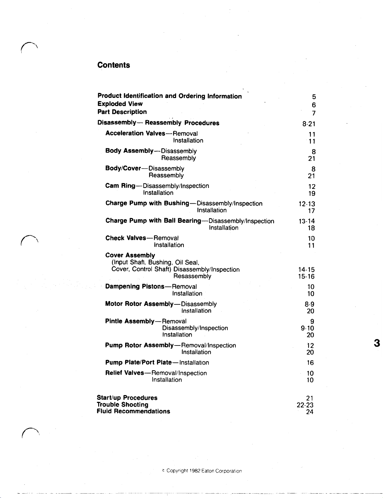
Contents
Product Identification and Ordering Information
Exploded View
Part Description
Disassembly- Reassembly Procedures
Acceleration Valves-Removal
Installation
Body
Assembly-Disassembly
Reassembly
Body/Cover-Disassembly
Reassembly
Cam
Ring-Disassembly/lnspection
Installation
Charge Pump with
Charge Pump with Ball
Check Valves-Removal
Cover Assembly
(Input Shaft, Bushing,
Cover, Control Shaft) Disassembly/lnspection
Dampening Pistons-Removal
Rotor
Motor
Pintle Assembly-Removal
Pump Rotor
Pump Plate/Port Plate-Installation
Relief
Valves-Removal/Inspection
Assembly-Disassembly
Assembly-Removal/lnspection
Bushing-Disassembly/lnspection
Installation
Bearing-Disassembly/lnspection
Installation
Installation
Oil
Seal,
Resassembly
Installation
Installation
Disassembly/lnspection
Installation
Installation
Installation
5
6
7
8-2 1
11
11
8
21
8
21
12
19
12-13
17
13-14
18
10
11
14-15
15-16
10
10
8-9
20
9
9- 10
20
12
20
16
10
10
3
Start/up Procedures
Trouble Shooting
Fluid Recommendations
Copyright
1982
Eaton Corporatlon
21
22-23
24
Page 4
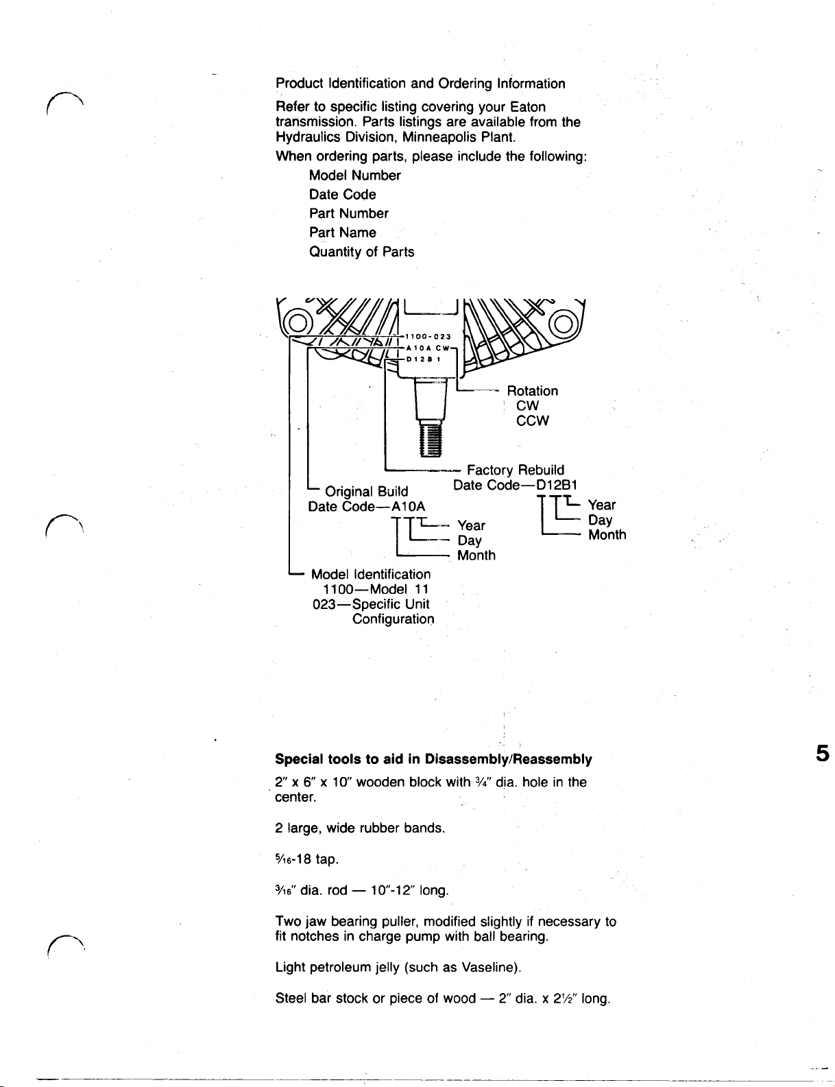
Product Identification and Ordering Information
Refer
to
specific listing covering your Eaton
transmission. Parts listings are available from the
Hydraulics Division, Minneapolis Plant.
When ordering parts, please include the following:
Model Number
Date Code
Part Number
Part Name
Quantity of Parts
Rotation
cw
ccw
Factory Rebuild
Original Build
Date Code-A1OA Year
Model Identification
1
1 00-Model 1 1
023-Specific Unit
Configuration
Date Code-Dl 2B1
Month
Day
Month
Special
2"
center.
2 large, wide rubber bands.
5/16-18 tap.
3/16"
Two jaw bearing puller, modified slightly if necessary
fit notches in charge pump with ball bearing.
Light petroleum jelly (such as Vaseline).
Steel bar stock or piece
tools
to
aid in Disassembly/Reassembly
x
6"
x
10"
wooden block with
dia. rod 10"-12" long.
3/4”
of
wood 2" dia.
dia. hole in the
x
2%"
long.
5
to
Page 5
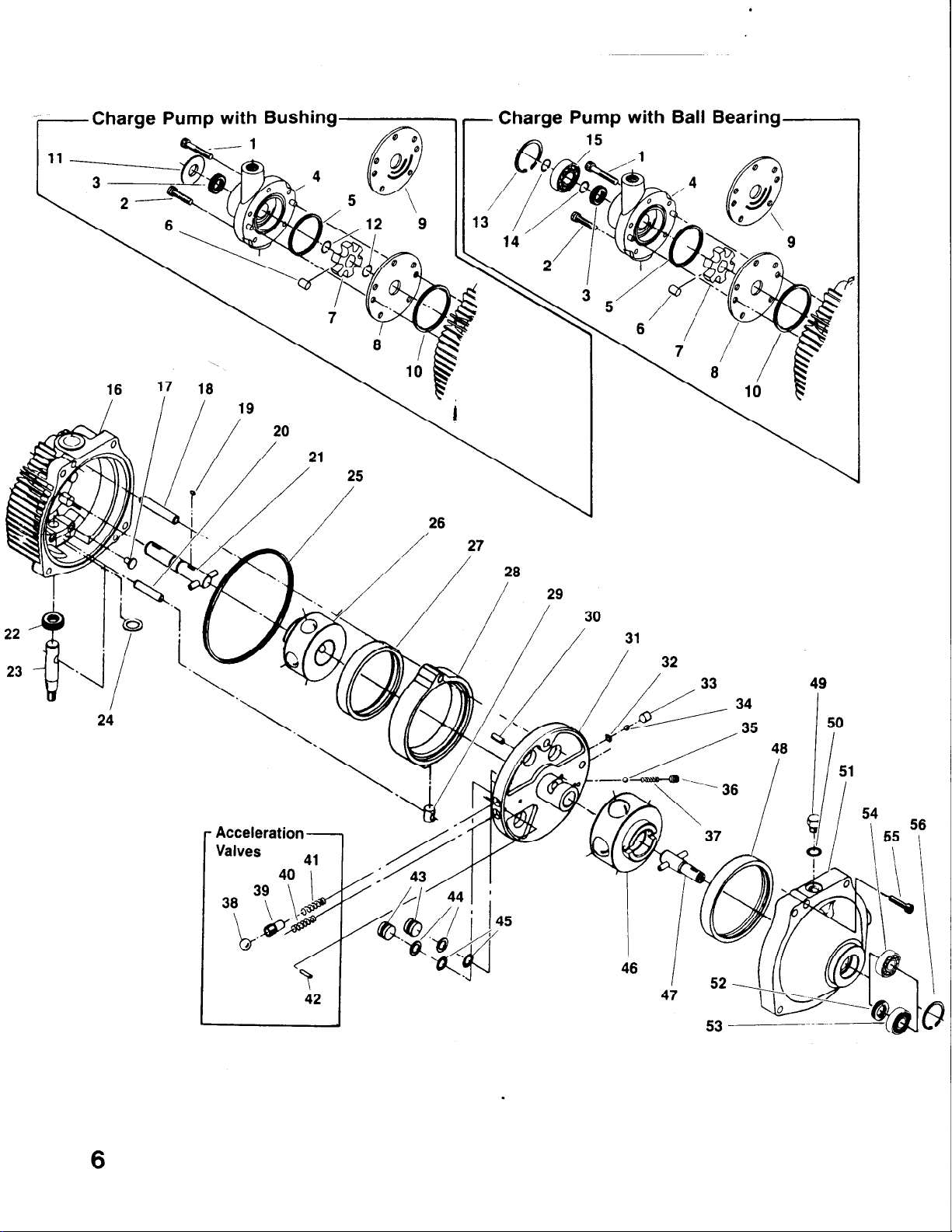
Charge Pump with Bushing
Charge Pump with Ball Bearing
24
I
Acceleration Valves
40 9’
39
38
\ l4
.&Tw
,
&
/
I
42
6
Page 6
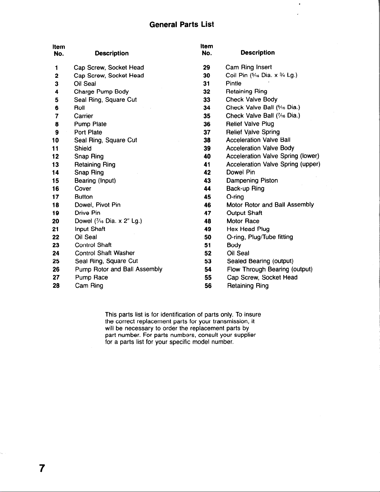
General Parts List
Item
No.
1
2
3
4
5
6
7
8
9
10
11
12
13
14
15
16
17
18
19
20
21
22
23
24
25
26
27
28
item
Description
No.
Cap Screw, Socket Head 29
Cap Screw, Socket Head 30
Oil Seal 31
Charge Pump Body
Seal Ring, Square Cut
Roll
Carrier
Pump Plate
Port Plate
32
33
34
35
36
37
Seal Ring, Square Cut 38
Shield 39
Snap Ring
Retaining Ring
40
41
Snap Ring 42
Bearing (Input)
Cover
Button
Dowel, Pivot Pin
Drive Pin
Dowel (36 Dia. x 2” Lg.)
Input Shaft
Oil Seal
Control Shaft
Control Shaft Washer
Seal Ring, Square Cut
Pump Rotor and Ball Assembly
Pump Race
Cam Ring
43
44
45
46
47
48
49
50
51
52
53
54
55
56
Description
Cam Ring Insert
Coil Pin
(%6
Dia. x % Lg.)
Pintle -
Retaining Ring
Check Valve Body
Check Valve Ball
(%6
Dia.)
Check Valve Ball (X6 Dia.)
Relief Valve Plug
Relief Valve Spring
Acceleration Valve Ball
Acceleration Valve Body
Acceleration Valve Spring (lower)
Acceleration Valve Spring (upper)
Dowel Pin
Dampening Piston
Back-up Ring
O-ring
Motor Rotor and Ball Assembly
Output Shaft
Motor Race
Hex Head Plug
O-ring, Plug/Tube fitting
Body
Oil Seal
Sealed Bearing (output)
Flow Through Bearing (output)
Cap Screw, Socket Head
Retaining Ring
7
This parts list is for identification of parts only. To insure
the correct replacement parts for your transmission, it
will be necessary to order the replacement parts by
part number. For parts numbers, consult your supplier
for a parts list for your specific model number.
Page 7
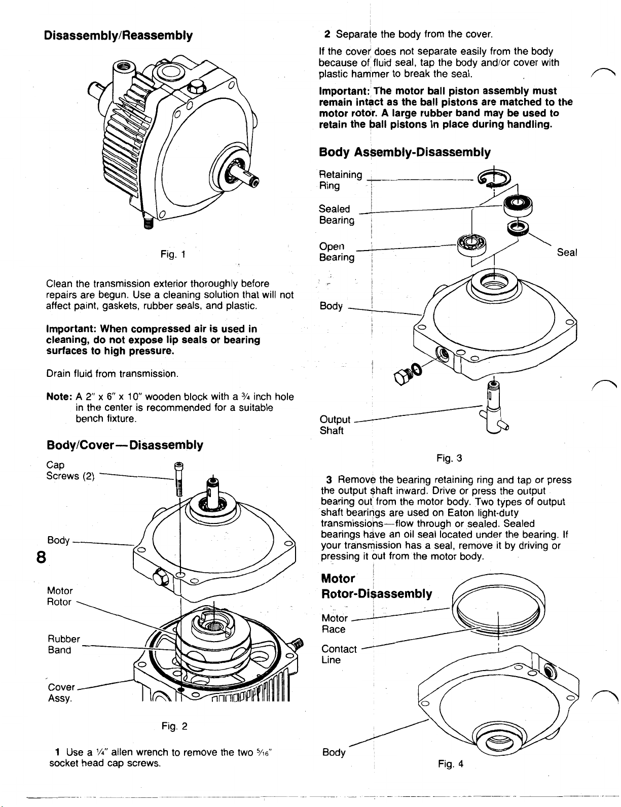
Disassembly/Reassembly
2
Separate the body from the cover.
If
the cover' does not separate easily from the body
because of' fluid seal, tap the body and/or cover with
plastic hammer to break the seal.
Important: The motor ball piston assembly must
remain intact as the ball pistons are matched to the
motor rotor.
retain the
A
large rubber band may be used to
ball
pistons in place during handling.
Body Assembly-Disassembly
Retaining
Ring
Sealed
Bearing
Fig.
1
Clean the transmission exterior thoroughly before
repairs are begun. Use a cleaning solution that will not
affect paint, gaskets, rubber seals, and plastic.
Important: When compressed air is used in
cleaning, do not expose lip seals or bearing
surfaces to high pressure.
Drain fluid from transmission.
Note:
A
2"
x
6"
x
10
wooden block with a
3/4
inch hole
in the center is recommended for a suitable
bench fixture.
Body/Cover- Disassembly
8
Open
Bearing Seal
Body
output
Shaft
Fig.
3
3
Remove the bearing retaining ring and tap or press
the output $haft inward. Drive or press the output
bearing out' from the motor body. Two types of output
shaft bearings are used on Eaton light-duty
transmissions-flow through or sealed. Sealed
bearings have an oil seal located under the bearing.
your transmission has a seal, remove it by driving or
pressing it out from the motor body.
If
1
Use a
l/4"
allen wrench to remove the two
socket head cap screws.
Fig.
2
5/16"
Fig.
4
Page 8

4
Inspect the contact line of the motor ball pistons-on Motor
in
be
damaged.
Fig.
body. This contact area must Rotor
If
it
is
7
Fig.
Pintle Assembly- Removal
5
the motor race located
be smooth and completely free of any irregularities.
any irregularities are noted, replace the motor race.
If
Note:
reasonable to assume that one or more ball pistons and
rotor bores will also
Motor
Rotor
Assy.
irregularities are noted in the motor race,
Assy.
Pintle
Assy.
Cover
Assy.
ubber
Band
5
Hold the pintle assembly in position against the
cover and remove the motor rotor assembly intact.
Rotor assembly out.
Bore
Piston ball
Fig.
6
6
Inspect the rotor assembly. Remove the piston balls
from the rotor, one at a time, by working clockwise from
the letter stamped in the face of the rotor and placing in
a prepared container.
Note: Each ball must be replaced in the same bore
from which it was removed. Use a suitable container for
piston ball storage such as an egg carton or ice cube
tray.
7
Inspect the piston balls. They must be smooth and
completely free of any irregularities.
Fig. 8
9
Hold the pump assembly in the bottom position and
tap lightly on the cover. Use a wood or plastic hammer
so
as not to damage aluminum cover. Lift the pintle
Important: The pump ball piston assembly must
as
remain intact
pump rotor. Use a wide rubber band
pistons
Pintle
Plugs
pintle
Assembly-Disassembly/lnspection
(2)
the ball pistons are matched to the
to
retain the
in
place
during
handling.
Bearing
8
Inspect rotor bores, rotor bushing and pintle journals Fig.
for irregularities or excessive clearance. The ball piston
fit
to rotor bore clearance is select
\.0002
to
.0006
of an inch. When irregularities or
excessive clearance are noted, replace the complete
rotor assembly.
Install motor ball pistons in their matching bores. Hold Note:
them in place with a rubber band.
electronically to
10
pintle assembly for cleaning. Normal flushing should
all that is required. However,
required, use the following procedures:
pintle journal.
we
do
not
Do
not remove the
9
complete
if
two
large plugs located on
disassembly
complete disassembly is
of
the
be
Page 9

Relief
Valve-Removal/lnspection
Dampening Piston-Installation
Relief Valve Plug
Ball position.
15
Install new back-up rings nearest to the smooth
piston face and O-rings in grove on a new piston.
16
Lubricate outer surface of the pistons. Press pistons
(smooth face up) in bores in pintle to the bottom
Check Valve-Removal
Note:
Removal of check valves is not necessary
check valve balls move freely and seat properly.
Fig. 10
11
Use a
1/4”
allen wrench to remove relief valve plug.
Then remove spring and ball.
12
Inspect all parts for irregularities. Replace any
defective part.
Relief Valve-Installation
13
Install ball, spring and plug in pintle. Screw plug in
Do
to just below surface of pintle.
not tighten
Check Valve
Body
Dampening Piston- Removal
if
Note:
Remove only
Dampening
Piston
Bolt Glued
To Piston
if
surface is scored.
lo
O-ring Seals (2)
Fig. 11
14
To remove pistons, firmly tap the outside edge of
pintle on a work surface. Remove back-up ring and
O-ring from pistons.
Important: When dislodging dampening pistons, do
not hit pintle journals or the pintle housing
ruined.
If
Note:
use adhesive to cement a bolt or similar object to the
pistons and pull them from the bore.
tapping of pintle does not dislodge the pistons,
will
be
Retaining'
(2)-
Rings
17
Press or drive out the coil pin that retains the
check valve bodies. Use a four blade 5/16-18 tap to tap
holes in check valve bodies. Insert a long bolt or a
puller, pull the check valve bodies from the pintle
housing and discard them.
18
Remove check balls and retaining ring.
Note:
On
23-25
for check valve removal.
19
Inspect check valve balls and retaining rings.
Replace any defective parts.
Coil Pin
Fig. 12
two
units with acceleration valves-see steps
Page 10

Check
20
of pintle. Press new check valve bodies in bores. Press
far enough in for coil pin clearance.
Valve-Installation
Install retaining rings and check valve balls
in
bores
Important:
do
not
21
Press coil pin into pintle until flush with or slightly
below surface.
To
prevent dislodging
drive check valve bodies into bores.
of
retaining rings
Acceleration Valves- Removal
Note:
Not all models have acceleration valves.
model has them-they are located directly opposite the
check valves.
See Figure 13,
If
your
3/16"
Dia.
Rod
Fig. 15
Check Replace Ball
Valve
Fig. 16
24
Insert the rod through the check valve body against
the acceleration valve body and drive both the valve
body and ball out of the bore. Repeat method for
second valve body and ball. Remove springs.
Note:
Some models use different springs for forward
and reverse. Be sure to identify the springs with the
so
acceleration valves
same bore from which they were removed.
they can be replaced in the
Acceleration
in
Check Valve
Valves
Body.
Fig. 13
22
Press solid pin from pintle housing. See Figure 13.
3/16"
Dia. Check Valve Body Check Valve
Rod Ball
\
Fig. 14
23
Insert
3/16
diameter rod through the check valve
(see
body. Tap the rod against the
ball to dislodge the retaining rings. Repeat for the
second check valve ball and ring. Shake dislodged
rings and balls out the large port area of pintle journal.
Fig. 14) check valve
25
Press or drive coil pin from pintle housing. Replace
the ball through the port into the check valve body.
3/16
Place the
valve bore against the check valve ball and drive the
check valve body and ball from the pintle housing.
Repeat this method for the second check valve body.
diameter rod through the acceleration
Acceleration Valves-Installation
26
Clean all parts thoroughly. Inspect parts for defects.
Replace all defective parts, including retaining rings,
which were damaged when driven out of their seats.
27
Install acceleration valve springs and acceleration
valves. Be sure that both acceleration valve bodies
slide freely in the bores and that the orifices are clean.
28
Press the two balls against the acceleration valve
bodies until the solid pin will clear. Press or drive the
dowel pin in
pintle surface.
29
Install new check valve retaining rings and balls in
pintle bores.
30
Press new check valve bodies into bores until coil
will
pin
clear.
so
it is flush with or slightly below the
11
Page 11

Important: Use a press to install check valve
bodies. Driving them into position
retaining rings.
31
Press or drive the coil pin in
below pintle surface.
may
dislodge the
to
flush or slightly
Pump Rotor AssemblyRemoval/lnspection
Rotor Assy.
Pump
Rubber
Band
33
Slide the cam ring from the pivot pin and control
shaft in the cover. Then lift ring from the cover.
34
Remove the control shaft insert.
35
Inspect area where the ball pistons contact the
race. This: area must be-smooth and completely free of
irregularities.
Note:
The pump race is press fit in the cam ring and
will require a press
pump race are available as an assembly.
If
it is not, replace the pump race.
19
Fig.
to
remove it. The cam ring and
Fig.
17
32
Remove seal from cover, lift pump rotor assembly
intact from the cover assembly.
Important:
pistons in place during handling. The pump ball
piston assembly must remain intact
pistons are matched to the pump rotor.
If
complete disassembly, inspection and reassembly of
pump rotor is necessary follow same procedures as for
motor rotor-see steps
Use
a wide rubber band to retain the ball
as
the ball
5
through
8.
Cam Ring-Disassembly/lnspection
12
Control Insert Shaft
36
Remove the two buttons from cover.
Charge' Pump with Bushing-Disassembly/
Inspection
Note:
Before removing the charge pump polish the
to
input shaft
Socket
Head
Cap
'Screws
Shield
Charge
Pump
remove paint, burrs, nicks, etc.
(5)
Fig.
18
Buttons
Control
Shaft
Fig.
37
Remove shield.
38
Use
a
1/4”
allen wrench
cap screws.
39
Carefully remove the charge pump.
to
20
remove the 5 socket head
Page 12

40
Remove the square cut seal from the charge pump
housing.
Fig.
21
41
Press or drive the oil seal from the charge pump
Important: Be careful not to damage the input
shaft bushing.
Top Snap
51
Use
1/4”
allen wrench to remove five cap screws.
Fig.
23
Use a modified two jaw bearing puller, pulling
52
two
against the
remove the charge pump assembly.
notches machined in the housing to
Ring
Carrier
Rolls
(6)
Fig.
22
42
Remove six carrier rolls.
43
Remove top snap ring from input shaft.
44
Mark top of carrier indicating which side is up.
Important:
manner that would damage the carrier surface.
Do
not mark the
roll
carrier in such a
Important:
removing the charge pump body. Apply a steady
pull only.
Important:
shaft during removal
Remove the square cut seal from the pump
53
assembly.
Pump
Do
not pound on the bearing puller while
Do
not damage the bore
of
charge pump.
for
the input
13
45
Remove carrier and drive pin. Fig.
46
Remove lower snap ring and pump or port plate. charge pump. Discard the
47
Inspect the input shaft bushing, carrier, rolls and
If
inner race contact areas in the charge pump.
irregularities are found, replace the complete pump
assembly.
48
Remove square cut seal from cover.
any
Charge Pump with Ball Bearing-
Disassembly/lnspection
49
Remove pump retaining ring. See Figure
50
Remove shaft retaining ring.
24.
24
54
Remove the bearing and the oil seal from the
Pump
Fig.
oil
seal.
25
Page 13

Snap
62
Reposition cover assembly as shown
Then remove input shaft.
in
Figure 27.
Carrier
Rolls
(6)
Fig. 26
55
Remove six carrier
56
Remove snap ring.
57
Mark top of carrier indicating which side is up.
Important:
would damage the carrier surface.
58
Remove carrier and carrier drive pin from input
shaft.
Do
not mark the roll carrier in a way that
rolls.
Important: Be careful not to damage the input shaft
bushing in the cover.
63
Inspect, input shaft for stripped keyways or other
irregularities.
64
Inspect, bushing located in face of cover for broken
bushing
cover.
65
Use a sharp narrow edged tool to pierce the top
metal part :of the oil seal and remove seal from the
cover.
Important:
distort the seal counter bore when removing seal.
If
found, replace the input shaft.
or
other irregularities.
Do
not scratch the control shaft or
Fig. 28
If
found, replace the
Oil Seal
Ass’y
n
59
Remove pump (or port) plate.
Remove square cut seal from cover and discard.
60
Inspect the ball bearing.
present, replace the bearing.
61
Inspect the carrier, rolls, inner race contact areas in
the charge pump housing and pump plate.
irregularities are found, replace the complete charge
pump assembly.
Cover
Assembly-Disassembly/lnspection
If
any irregularities are
If
any
Inspect cover assembly, especially around the
66
if
control shaft area. Replace the cover assembly
if
broken, cracked or
shaft and Cover exceeds .006".
67
In most cases, it
the control shaft from the cover.
broken in the control shaft, remove the shaft using the
following procedures.
Measure this Distance Control
side clearance between control
will
not be necessary to remove
If
the dowel is loose or
it is
Shaft
Fig. 27
Fig. 29
68
Measure the distance between center of dowel pin
and the end of the shaft as shown in Figure 29.
Page 14
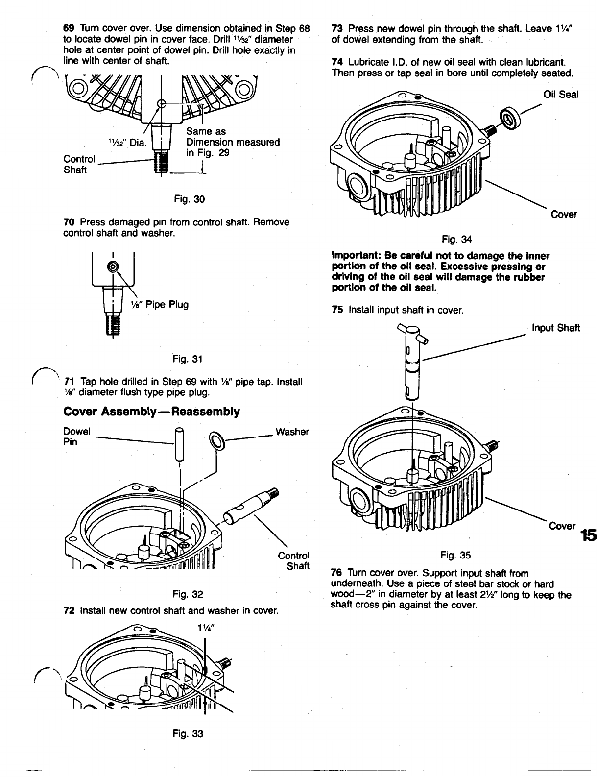
69
Turn cover over. Use dimension obtained in Step
to locate dowel pin in cover face. Drill
11/32”
diameter
hole at center point of dowel pin. Drill hole exactly in
of
line with center
shaft.
Same as
Dimension measured
Control
in Fig.
29
Shaft
Fig.
30
Press damaged pin from control shaft. Remove
70
control shaft and washer.
68
73
Press new dowel pin through the shaft. Leave
1
1/4”
of dowel extending from the shaft.
74
Lubricate I.D.
of
new oil seal with clean lubricant.
Then press or tap seal in bore until completely seated.
Cover
Fig.
34
important: Be careful not to damage the inner
portion of the oil seal. Excessive pressing or
of
driving
the oil
portion of the oil
seal
seal.
will
damage the rubber
Pipe Plug
31
Fig.
71
Tap hole drilled in Step
1/8”
diameter flush type pipe plug.
69
with
1/8”
pipe tap. Install
Cover Assembly-Reassembly
Dowel
Pin
32
Fig.
72
Install new control shaft and washer in cover.
Washer
75
Install input shaft in cover.
input Shaft
Fig.
35
Turn cover over. Support input shaft from
76
underneath. Use a piece of steel bar stock or hard
wood-2 in diameter by at least
2 1/2”
long to keep the
shaft cross pin against the cover.
15
Fig.
33
Page 15

Fig.
36
77
Lightly lubricate new square cut seal and install in
seal groove in cover.
Pump
Plate
(or Port
Plate)
Seal
Outlet
r
Outlet Outlet
Port (Inlet)
Plate
Identification
16
’
Cover
Fig.
37
Pump Plate/Port Plate-Installation
78 Install pump plate or port plate on cover. Either side
of
the pump plate may face.
input rotation. However, the port plate must be installed
per specific input rotation. See Figure
Important: Stamping on cover indicates
pump rotation is clockwise or counter clockwise.
the
cover regardless
38.
if
charge
of
Pump Plate
38
Fig.
Page 16

79
For counter clockwise (CCW) rotation, the letter
must be up, facing the charge pump. For clockwise shaft (against carrier).
(CW) rotation the letter
A
must face down toward the
A
82
Install snap ring in upper snap ring groove in input
Snap Ring
cover
Charge Pump with Bushing-Installation
For charge pumps with ball bearing, see Steps
through
Install snap ring in lower snap ring groove (against
plate) of input shaft.
Snap Carrier
Ring Drive
Lower
Snap
Ring Groove
80
a small amount
pin
Carrier rubber lip toward the bore. Make sure seal is
Rolls
94
for installation.
Fig.
39
Install carrier drive pin in keyway
of
petroleum jelly or equivalent to hold
in
place.
(6)
of
input shaft. Use in the carrier.
89
Fig.
42
Lightly lubricate the six carrier rolls and install them
83
84
Lubricate inner surface of new oil seal and install in
charge pump housing as shown in Figure
completely seated.
I
43
with the
Fig.
40
Install carrier over input shaft with side marked “up”
81
57).
(see step
drive pin in output shaft.
Important: For correct carrier rotation the leading
edge of carrier must rotate in the same direction as
the input shaft. Install as shown in Figure 41.
Be sure keyway in carrier fits over carrier
Toward Bore
New Oil Seal
Fig.
43
Important: Excessive pressing or force on oil seal
may cause damage to rubber sealing portion or
may distort counterbore of housing.
Square
cut
Seal
Charge
Pump
44
Fig.
Lightly lubricate new square cut seal with petroleum
85
of
jelly and, install in seal groove
pump housing.
17
Fig.
41
Important:
it
inlet,
pump.
Charge
must be installed before mounting charge
pump
If
an elbow fitting
wlth
Bearlng
see
page
is
used in the pump
18
Page 17

86
Align charge pump dowel pins with holes in cover.
Then guide pump over shaft, carrier and rolls until pins
engage holes.
Important: Protect oil seal lip from keyways, snap
ring grooves and shaft splines.
Screw (4)
5/16"
1' 1/4”
90
Install carrier over input shaft with side marked "up"
(see step
drive pin in input shaft.
Important: For correct carrier rotation the leading
edge of carrier must rotate in the same direction as
the input shaft. Install as shown
57).
Be sure keyway in carrier fits over carrier
in
Figure
48.
Screw
5/16"
Shield
Fig. 45
87
Install 4 screws
1 3/4”
in pump housing. Torque
Important: Install 1 3/4”
charge pump body. If installed and tightened in any
of the other four holes, internal damage could
occur.
88
Install protective shield on housing.
Important: Install protective shield
is
pointing away from oil
seal
oil
if installed improperly.
(5/16"
x
1 1/4”
screw
seal.
and one screw
to
15
foot pounds.
in
thicker section of
so
that flange
Shield may damage
(1)
13/4"
Charge
Pump
Housing
5/16”
x
\
Leading Edge
ccw
Fig. 48
91
Lightly lubricate and install the six carrier rolls in the
a
carrier. Use'
equivalent
Toward
to
small amount
hold the rolls in place.
of
petroleum jelly
or
Char
Installation
18
89
Lubricate carrier drive pin and install in keyway
input shaft.
e
Pump
with Ball Bearing-
Fig. 46
Fig.
47
Carrier
Drive
Carrier
Rolls
Carrier
of
49
Fig.
92
Lubricate inner surface
charge pump housing as shown in Figure 49 with the
rubber lip toward the bore. Make sure seal is
completely seated
Important: 'Excessive pressing or force on
may cause damage to rubber sealing portion or
may distort counterbore
Square
cut
Seal
(6)
Charge
Pump
I
93
Lightly lubricate new square. cut seal and install in
seal groove
Important: If an elbow fitting
inlet,
pump.
of
pump housing.
it
must be installed before mounting charge
of
new oil seal and install in
of
housing.
Fig.
50
is
used in the pump
oil
seal
Page 18

94
Align charge pump dowel pins with holes in cover.
Protect
shaft splines. Then guide pump over shaft, carrier and
rolls until pins engage holes.
Screw (4)
Charge
Pump
Housing
oil
seal lip from keyways, snap ring grooves and
Retaining
Ring
53
Fig.
Important: Input shaft should rotate freely by hand.
If
it does not, recheck installation.
Fig. 51
95
Install 4 screws
1 3/4”) in pump housing. Torque
Important: Install 1
charge pump body.
of the other four holes, internal damage could
Occur-
Upper Snap Ring
Snap Ring
(5/16”)
x
1 1/4”) and one screw
to
15 foot pounds.
3/4”
screw in thicker section of
If
installed and tightened in any
5/16"
x
Cam
100
Figure 54.
Ring-Installation
Install 2 buttons
in
the cover as shown in
Fig. 54
Cam
Control
Block
52
Fig.
96
Install snap ring in lower groove of input shaft.
97
With cover assembly separated from the body and
the input shaft properly supported (see Figure
input shaft bearing may be pressed into position.
to
Press
lousing against the retaining ring.
98
against inner bearing race.
99
housing.
the bottom position in the charge pump
Install snap ring in upper groove of input shaft
Install large snap ring used
to
retain bearing in
52)
the
101
Install the cam ring insert with the hole away from
the cam ring as shown in Figure 54.
102
Align the cam ring with the control shaft pin and
the cam ring pivot pin.
Install the cam ring with the flush side
race facing the cover. Press in firmly until the cam ring
has bottomed in the cover assembly.
Important: Cam ring must move freely from stop to
If
stop.
ring insert 180". Check the cam ring movement
again.
binding occurs at either stop rotate the cam
of
the bearing
19
Page 19

Pump Rotor Assembly-Installation
103
Align the
cross
pin. Install
Important: Keep rotor assembly intact with wide
rubber band. Remove rubber band after installing
rotor assembly
slot
in the pump
rotor
assembly on shaft.
in
cover assembly.
Fig.
55
rotor
with the input shaft
Do
Important:
It is a slip fit and the pintle must turn freely by
hand.
If
it
not force pintle over rotor assembly.
,does not, recheck the pintle installation.
Motor Rotor Assembly-Installation
106
Install the motor
Figure
Important:
pintle.
by hand.
Keep the
Remove rubber band after installing
Motor
Rotor
Assy
Rubber
Band
57.
Do
It
is a slip fit and
rotor
assembly intact with wide rubber band.
!
rotor
assembly on the pintle. See
not force the rotor assembly over the
the
rotor must rotate freely
rotor
assembly.
Pintle Assembly-Installation
Note:
To
determine pintle rotation, place a small
or
ruler
Figure
straight edge in the porting slot as shown in
56.
Pintle
Cam Ring
Pivot Pin
Fig.
Fig.
56
104
Align dowel pin hole in pintle assembly with cam
rotor
ring pivot pin and install over pump
105
Lightly grease a new square cut seal and install it
in the groove in the housing.
assembly.
Page 20

Body Assembly-Reassembly
Note:
Transmissions with sealed bearings incorporate
an oil seal under the output bearing.
“Retaining Sealed
Ring
Flow
Through
Bearing
Body/Cover-Reassembly
111
Install body. Align the output shaft with the bearing
1ocated: in pintle and shaft cross pin with the
5/16”
motor rotor assembly. Install two
15
cap screws Torque to
Important: Be sure the output shaft rotates freely
by hand. If it does not, recheck body installation.
5/16”
x
1
1/4”
(2)
foot pounds.
x
slot
1
1/4”
socket head
in the
Output Shaft
58
Fig.
107
When applicable, install oil seal in body with the
rubber lip toward the counter bore in the body. Press or
tap the seal into the bottom position in the counter
bore.
Important:
This may damage the rubber sealing portion
oil seal.
108
Install output bearing. Position bearing on the body
and press on the outer bearing race to the bottom
position in the body.
109
Install the bearing retaining ring.
110
Install output shaft. This is a press fit. Be sure to
support the inner race of the ball bearing while pressing
the shaft into the bearing.
Do
not over press or drive the oil seal.
of
the
Fig.
59
Start-up Procedure
112
Fill transmission with fluid. See page
recommendations. On transmission
flow through output bearing, fill through the axle
manufacturer’s specified fluid level.
On transmissions that incorporate sealed output shaft
bearing$, fill through the reservoir to the manufacturer’s
specified fluid level. Start the engine and run the
transmission in both directions at low engine speed for
a short time
Stop,
The transmission is now ready for use.
to
purge trapped air from the system.
shut off engine and recheck fluid level.
that
incorporates
24
for fluid
to
the
21
Page 21

Trouble Shooting Instructions
This fault-logic troubleshooting section is designed as a
diagnostic aid in locating transmission problems.
Match the transmission problem with the problem,
statements and follow the action steps shown in the
diagrams. This will give the user expedient aids in
correcting the problem and eliminating unnecessary
machine down time.
System Jerky/Noisy when Starting
22
Defective
Defective
I
Serviceable
Externally
System Operates in One Direction Only
Defective Defective Defective
Repair
I
or
Replace
I
Serviceable
Serviceable
Page 22

External
LOSS
Will
Not Operate in Either Direction
of
Power or System
Clogged
Replace
Defective
System Operating Hot
Defective Clogged
Replace
Defective
or
Replace
Transmission
Cooling Fins
Defective
I
Serviceable
Externally
23
Page 23
EATON
HYDROSTATIC TRANSMISSION
MODEL
"REPAIR
NO.
I.
11
MANUAL
7-402
Fluid
A
reputable supplier can help you make
Eaton light duty hydrostatic transmissions.
For satisfactory operation, the following fluid conditions apply:
1. Accurate level readings can be checked only when the fluid
2.
If
the natural color of the fluid has become black or milky,
contaminant problem exists.
3.
Proper viscosity is essential. At normal operating temperatures, the optimum range is between
80-180
4. The fluid should
Specific types of fluid meeting these requirements may be:
(1)
Premium hydraulic oil
(2)
Engine crankcase
(3)
Automatic transmission oil
(4)
Hydraulic transmission oil
Recommendations'-
the
best selection of hydraulic fluid for use in
SUS
(16-40
cSt
),
and it should never fall below 60
be
chemically stable, incorporating rust and oxidation inhibitors.
oil
I
is
cold.
it
is possible that an overheating or water
SUS
(10
cSt
).
Heprinted
with
permission
Part
#492-4310
 Loading...