

Page 1

Groundsmaster 580-D
Traction and Cutting Units
Model No. 30581—230000001 and Up
Form No. 3328–909
Operator’s Manual
English (EN, GB)
Page 2

Warning
CALIFORNIA
Proposition 65 Warning
Diesel engine exhaust and some of its constituents
are known to the State of California to cause
cancer, birth defects, and other reproductive harm.
Contents
Introduction 3. . . . . . . . . . . . . . . . . . . . . . . . . . . . . . . . .
Safety 3. . . . . . . . . . . . . . . . . . . . . . . . . . . . . . . . . . . . . .
Safe Operating Practices 3. . . . . . . . . . . . . . . . . . . .
Toro Riding Mower Safety 5. . . . . . . . . . . . . . . . . . .
Sound Pressure Level 6. . . . . . . . . . . . . . . . . . . . . . .
Sound Power Level 6. . . . . . . . . . . . . . . . . . . . . . . .
Vibration Level 6. . . . . . . . . . . . . . . . . . . . . . . . . . . .
Safety and Instruction Decals 7. . . . . . . . . . . . . . . . .
Specifications 12. . . . . . . . . . . . . . . . . . . . . . . . . . . . . . . .
Traction Unit 12. . . . . . . . . . . . . . . . . . . . . . . . . . . . .
All Cutting Units 13. . . . . . . . . . . . . . . . . . . . . . . . . .
Triflex Cutting Unit (Front) 13. . . . . . . . . . . . . . . . .
Outboard Cutting Units 14. . . . . . . . . . . . . . . . . . . . .
Dimensions 14. . . . . . . . . . . . . . . . . . . . . . . . . . . . . .
Optional Equipment 14. . . . . . . . . . . . . . . . . . . . . . . .
Setup 15. . . . . . . . . . . . . . . . . . . . . . . . . . . . . . . . . . . . . .
Checking the Batteries 15. . . . . . . . . . . . . . . . . . . . . .
Before Operating 16. . . . . . . . . . . . . . . . . . . . . . . . . . . . .
Checking the Engine Oil 16. . . . . . . . . . . . . . . . . . . .
Checking the Cooling System 17. . . . . . . . . . . . . . . .
Checking the Hydraulic System Fluid 17. . . . . . . . . .
Filling the Fuel Tank 17. . . . . . . . . . . . . . . . . . . . . . .
Checking the Tire Pressure 18. . . . . . . . . . . . . . . . . .
Checking Systems Operation 18. . . . . . . . . . . . . . . . .
Checking Cutting Unit Mismatch 18. . . . . . . . . . . . .
Adjusting the Height of Cut 18. . . . . . . . . . . . . . . . . .
Adjusting the Skids 19. . . . . . . . . . . . . . . . . . . . . . . .
Operation 20. . . . . . . . . . . . . . . . . . . . . . . . . . . . . . . . . . .
Controls 20. . . . . . . . . . . . . . . . . . . . . . . . . . . . . . . . .
Starting and Stopping the Engine 24. . . . . . . . . . . . . .
Bleeding the Fuel System 25. . . . . . . . . . . . . . . . . . . .
Page
Page
Diagnostic Light 25. . . . . . . . . . . . . . . . . . . . . . . . . . .
Diagnostic ACE Display 26. . . . . . . . . . . . . . . . . . . .
Checking the Interlock Switches 26. . . . . . . . . . . . . .
Checking the Warning Indicator Lights 30. . . . . . . . .
Pushing or Towing the Machine 30. . . . . . . . . . . . . .
Operating Characteristics 30. . . . . . . . . . . . . . . . . . . .
Maintenance 32. . . . . . . . . . . . . . . . . . . . . . . . . . . . . . . . .
Recommended Maintenance Schedule 32. . . . . . . . .
Daily Maintenance Checklist 34. . . . . . . . . . . . . . . . .
Lubrication 35. . . . . . . . . . . . . . . . . . . . . . . . . . . . . . .
Engine Oil and Filter 36. . . . . . . . . . . . . . . . . . . . . . .
Engine Fuel System 38. . . . . . . . . . . . . . . . . . . . . . . .
Engine Cooling System 38. . . . . . . . . . . . . . . . . . . . .
Servicing the Air Cleaner 40. . . . . . . . . . . . . . . . . . . .
Servicing the Hydraulic System 41. . . . . . . . . . . . . . .
Servicing the Planetary Gear Drive 43. . . . . . . . . . . .
Servicing the Battery 44. . . . . . . . . . . . . . . . . . . . . . .
Fuses and Circuit Breaker 45. . . . . . . . . . . . . . . . . . .
Servicing the Brake System 45. . . . . . . . . . . . . . . . . .
Wheels and Tires 45. . . . . . . . . . . . . . . . . . . . . . . . . .
Cutting Unit Lubrication 46. . . . . . . . . . . . . . . . . . . .
Blade Maintenance 46. . . . . . . . . . . . . . . . . . . . . . . . .
Blade Bolt Torque 47. . . . . . . . . . . . . . . . . . . . . . . . .
Removing the Cutting Unit Blade 47. . . . . . . . . . . . .
Inspecting and Sharpening the Blade 48. . . . . . . . . . .
Inspecting and Adjusting Cutting Unit Belt Tension 49.
Replacing the Blade Drive Belts 49. . . . . . . . . . . . . .
Separating Cutting Units from Traction Unit 51. . . . .
Checking and Correcting Cutting Blade Mismatch 51
Adjusting the Winglet Stabilizers 52. . . . . . . . . . . . .
Adjusting Traction Control Neutral 53. . . . . . . . . . . .
Adjusting the Traction (Neutral) Switch 53. . . . . . . .
Adjusting the Traction Control Rod 54. . . . . . . . . . . .
Cylinder Head Bolts 54. . . . . . . . . . . . . . . . . . . . . . . .
Engine Valve Clearance 54. . . . . . . . . . . . . . . . . . . . .
Electrical Schematic 55. . . . . . . . . . . . . . . . . . . . . . . .
Controller Electrical Schematic 56. . . . . . . . . . . . . . .
Hydraulic Schematic 57. . . . . . . . . . . . . . . . . . . . . . .
The Toro General Commercial Products Warranty 60. . .
2001 by The Toro Company
8111 Lyndale Avenue South
Bloomington, MN 55420-1196
All Rights Reserved
Printed in the USA
2
Page 3

Introduction
Read this manual carefully to learn how to operate and
maintain your product properly. The information in this
manual can help you and others avoid injury and product
damage. Although Toro designs and produces safe
products, you are responsible for operating the product
properly and safely.
Whenever you need service, genuine Toro parts, or
additional information, contact an Authorized Service
Dealer or Toro Customer Service and have the model and
serial numbers of your product ready. A plate with the
model and serial numbers is located on the left bulkhead
below the operator’s seat and on the rear channel of each
cutting unit.
Write the product model and serial numbers in the space
below:
Model No.
Improper use or maintenance by the operator or owner
can result in injury. To reduce the potential for injury,
comply with these safety instructions and always pay
attention to the safety alert
CAUTION, WARNING, or DANGER—“personal
safety instruction.” Failure to comply with the
instruction may result in personal injury or death.
symbol, which means
Safe Operating Practices
The following instructions are from the CEN standard EN
836:1997, ISO standard 5395:1990, and ANSI B71.4-1999.
Training
• Read the operator’s manual and other training material
carefully. Be familiar with the controls, safety signs,
and the proper use of the equipment.
• If the operator or mechanic can not read the language of
this manual, it is the owner’s responsibility to explain
this material to them.
Serial No.
This manual identifies potential hazards and has special
safety messages that help you and others avoid personal
injury and even death. Danger, Warning, and Caution are
signal words used to identify the level of hazard. However,
regardless of the hazard, be extremely careful.
Danger signals an extreme hazard that will cause serious
injury or death if you do not follow the recommended
precautions.
Warning signals a hazard that may cause serious injury or
death if you do not follow the recommended precautions.
Caution signals a hazard that may cause minor or moderate
injury if you do not follow the recommended precautions.
This manual uses two other words to highlight information.
Important calls attention to special mechanical
information and Note: emphasizes general information
worthy of special attention.
Safety
This machine meets or exceeds CEN standard EN
836:1997 (when appropriate decals applied), and ANSI
B71.4-1999 specifications in effect at the time of
production when equipped with required weights as
listed in the weight chart.
• Never allow children or people unfamiliar with these
instructions to use or service the mower. Local
regulations may restrict the age of the operator.
• Never mow while people, especially children, or pets
are nearby.
• Keep in mind that the operator or user is responsible for
accidents or hazards occurring to other people or their
property.
• Do not carry passengers.
• All drivers and mechanics should seek and obtain
professional and practical instruction. The owner is
responsible for training the users. Such instruction
should emphasize:
– the need for care and concentration when working
with ride-on machines;
– control of a ride-on machine sliding on a slope will
not be regained by the application of the brake. The
main reasons for loss of control are:
• insufficient wheel grip;
• being driven too fast;
• inadequate braking;
• the type of machine is unsuitable for the task;
• lack of awareness of the effect of ground
conditions, especially slopes;
3
Page 4

• The owner/user can prevent and is responsible for
accidents or injuries occurring to himself or herself,
other people, or property.
Preparation
• While mowing, always wear substantial footwear, long
trousers, hard hat, safety glasses, and hearing
protection. Long hair, loose clothing, or jewelry may
get tangled in moving parts. Do not operate the
equipment when barefoot or wearing open sandals.
• Thoroughly inspect the area where the equipment is to
be used and remove all objects which may be thrown by
the machine.
• Warning—Fuel is highly flammable. Take the
following precautions:
– Store fuel in containers specifically designed for this
purpose.
– Refuel outdoors only and do not smoke while
refueling.
– Add fuel before starting the engine. Never remove
the cap of the fuel tank or add fuel while the engine
is running or when the engine is hot.
– If fuel is spilled, do not attempt to start the engine
but move the machine away from the area of
spillage and avoid creating any source of ignition
until fuel vapors have dissipated.
– Replace all fuel tank and container caps securely.
• Replace faulty silencers/mufflers.
• Evaluate the terrain to determine what accessories and
attachments are needed to properly and safely perform
the job. Only use accessories and attachments approved
by the manufacturer.
• Check that operator’s presence controls, safety switches
and shields are attached and functioning properly. Do
not operate unless they are functioning properly.
• EU (European Union) standard EN836 requires a
maximum slope usage angle statement. This stated
angle is 50% of the smallest angle recorded during the
of stability test. For this product this statement is; Do
not use on slopes of more than 10°.
• Remember there is no such thing as a safe slope. Travel
on grass slopes requires particular care. To guard
against overturning:
– do not stop or start suddenly when going up or
downhill;
– machine speeds should be kept low on slopes and
during tight turns;
– stay alert for humps and hollows and other hidden
hazards;
– never mow across the face of the slope, unless the
mower is designed for this purpose.
– Use counterweight(s) or wheel weights when
suggested in the operator’s manual.
• Stay alert for holes in the terrain and other hidden
hazards.
• Watch out for traffic when crossing or near roadways.
• Stop the blades from rotating before crossing surfaces
other than grass.
• When using any attachments, never direct discharge of
material toward bystanders nor allow anyone near the
machine while in operation.
• Never operate the machine with damaged guards,
shields, or without safety protective devices in place. Be
sure all interlocks are attached, adjusted properly, and
functioning properly.
• Do not change the engine governor settings or
overspeed the engine. Operating the engine at excessive
speed may increase the hazard of personal injury.
• Before leaving the operator’s position:
– stop on level ground;
Operation
• Do not operate the engine in a confined space where
dangerous carbon monoxide fumes can collect.
• Mow only in daylight or in good artificial light.
• Before attempting to start the engine, disengage all
blade attachment clutches, shift into neutral, and engage
the parking brake.
• Do not put hands or feet near or under rotating parts.
Keep clear of the discharge opening at all times.
– disengage the power take-off and lower the
attachments;
– change into neutral and set the parking brake;
– stop the engine and remove the key.
• Disengage drive to attachments when transporting or
not in use.
• Stop the engine and disengage drive to attachment
– before refuelling;
– before removing the grass catcher/catchers;
– before making height adjustment unless adjustment
can be made from the operator’s position.
4
Page 5

– before clearing blockages;
– before checking, cleaning or working on the mower;
– after striking a foreign object or if an abnormal
vibration occurs. Inspect the mower for damage and
make repairs before restarting and operating the
equipment.
• Reduce the throttle setting during engine run-out and, if
the engine is provided with a shut-off valve, turn the
fuel off at the conclusion of mowing.
• Keep hands and feet away from the cutting units.
• Look behind and down before backing up to be sure of
a clear path.
• Slow down and use caution when making turns and
crossing roads and sidewalks. Stop blades from rotating.
• Be aware of the mower discharge direction and do not
point it at anyone.
• Do not operate the mower under the influence of
alcohol or drugs
• Use care when loading or unloading the machine into a
trailer or truck
• Use care when approaching blind corners, shrubs, trees,
or other objects that may obscure vision.
• Disengage drives, lower the cutting units, set parking
brake, stop engine and remove key and disconnect spark
plug wire (gas engine only). Wait for all movement to
stop before adjusting, cleaning or repairing.
• Clean grass and debris from cutting units, drives,
silencers/mufflers, and engine to help prevent fires.
Clean up oil or fuel spillage.
• Use jack stands to support components when required.
• Carefully release pressure from components with stored
energy.
• Disconnect battery and remove spark plug wire (gas
engine only) before making any repairs. Disconnect the
negative terminal first and the positive last. Reconnect
positive first and negative last.
• Use care when checking the blades. Wear gloves and
use caution when servicing them.
• Keep hands and feet away from moving parts. If
possible, do not make adjustments with the engine
running.
• Charge batteries in an open well ventilated area, away
from spark and flames. Unplug charger before
connecting or disconnecting from battery. Wear
protective clothing and use insulated tools.
Maintenance and Storage
• Keep all nuts, bolts and screws tight to be sure the
equipment is in safe working condition.
• Never store the equipment with fuel in the tank inside a
building where fumes may reach an open flame or
spark.
• Allow the engine to cool before storing in any
enclosure.
• To reduce the fire hazard, keep the engine,
silencer/muffler, battery compartment and fuel storage
area free of grass, leaves, or excessive grease.
• Check the grass catcher frequently for wear or
deterioration.
• Keep all parts in good working condition and all
hardware and hydraulic fittings tightened. Replace all
worn or damaged parts and decals.
• If the fuel tank has to be drained, do this outdoors.
• Be careful during adjustment of the machine to prevent
entrapment of the fingers between moving blades and
fixed parts of the machine.
• On multi-spindle mowers, take care as rotating one
blade can cause other blades to rotate.
Toro Riding Mower Safety
The following list contains safety information specific to
Toro products or other safety information that you must
know that is not included in the CEN, ISO, or ANSI
standard.
This product is capable of amputating hands and feet and
throwing objects. Always follow all safety instructions to
avoid serious injury or death.
Use of this product for purposes other than its intended use
could prove dangerous to user and bystanders.
Warning
Engine exhaust contains carbon monoxide, which
is an odorless, deadly poison that can kill you.
Do not run engine indoors or in an enclosed area.
• Know how to stop the engine quickly.
• Do not operate the machine while wearing tennis shoes
or sneakers.
• Wearing safety shoes and long pants is advisable and
required by some local ordinances and insurance
regulations.
• Handle fuel carefully. Wipe up any spills.
5
Page 6

• Check the safety interlock switches daily for proper
operation. If a switch should fail, replace the switch
before operating the machine. After every two years,
replace all interlock switches in the safety system,
whether they are working properly or not.
• Before starting the engine, sit on the seat.
• Using the machine demands attention. To prevent loss
of control:
– Do not drive close to sand traps, ditches, creeks,
embankments, or other hazards.
– Reduce speed when making sharp turns. A void
sudden stops and starts.
– When near or crossing roads, always yield the
right-of-way.
Maintenance and Storage
• Make sure all hydraulic line connectors are tight and all
hydraulic hoses and lines are in good condition before
applying pressure to the system.
• Keep your body and hands away from pin hole leaks or
nozzles that eject hydraulic fluid under high pressure.
Use paper or cardboard, not your hands, to search for
leaks. Hydraulic fluid escaping under pressure can have
sufficient force to penetrate the skin and cause serious
injury. Seek immediate medical attention if fluid is
injected into skin.
• Before disconnecting or performing any work on the
hydraulic system, all pressure in the system must be
relieved by stopping the engine and lowering the cutting
units and attachments to the ground.
– Apply the service brakes when going downhill to
keep forward speed slow and to maintain control of
the machine.
• When operating a machine on slopes, by banks, or drop
offs, always have ROPS (roll–over protection system)
installed.
• When operating a machine with ROPS (roll–over
protection system) always use the seat belt and make
sure seat pivot retainer pin is installed (GM only).
• Raise the cutting units when driving from one work
area to another.
• Do not touch the engine, silencer/muffler, or exhaust
pipe while the engine is running or soon after it has
stopped because these areas could be hot enough to
cause burns.
• On any hill, there is the possibility of tipping or rolling
over, but the risk increases as the slop angle increases.
Steep hills should be avoided.
– Cutting units must be lowered when going down
slopes to maintain steering control
• Engage traction drive slowly, always keep foot on
traction pedal, especially when traveling downhill.
– Use reverse on traction pedal for braking.
• If the machine stalls when climbing a slope, do not turn
the machine around. Always back slowly, straight down
the slope.
• Check all fuel lines for tightness and wear on a regular
basis. Tighten or repair them as needed.
• If the engine must be running to perform a maintenance
adjustment, keep hands, feet, clothing, and any parts of
the body away from the cutting units, attachments, and
any moving parts.
• To ensure safety and accuracy, have an Authorized Toro
Distributor check the maximum engine speed with a
tachometer.
• If major repairs are ever needed or if assistance is
desired, contact an Authorized Toro Distributor.
• Use only Toro-approved attachments and replacement
parts. The warranty may be voided if used with
unapproved attachments.
Sound Pressure Level
This unit has an equivalent continuous A-weighted sound
pressure level at the operator ear of: 91 dB(A), based on
measurements of identical machines per Directive
98/37/EC and amendments.
Sound Power Level
This unit has a guaranteed sound power level of:
105 dBA/1 pW, based on measurements of identical
machines per Directive 2000/14/EC and amendments.
• When a person or pet appears unexpectedly in or near
the mowing area, stop mowing. Careless operation,
combined with terrain angles, ricochets, or improperly
positioned guards can lead to thrown object injuries. Do
not resume mowing until the area is cleared.
Vibration Level
This unit does not exceed a vibration level of 2.5 m/s2 at
the hands based on measurements of identical machines per
ISO 5349 procedure.
This unit does not exceed vibration level of 0.5 m/s
posterior based on measurements of identical machines per
ISO 2631 procedures.
6
2
at the
Page 7
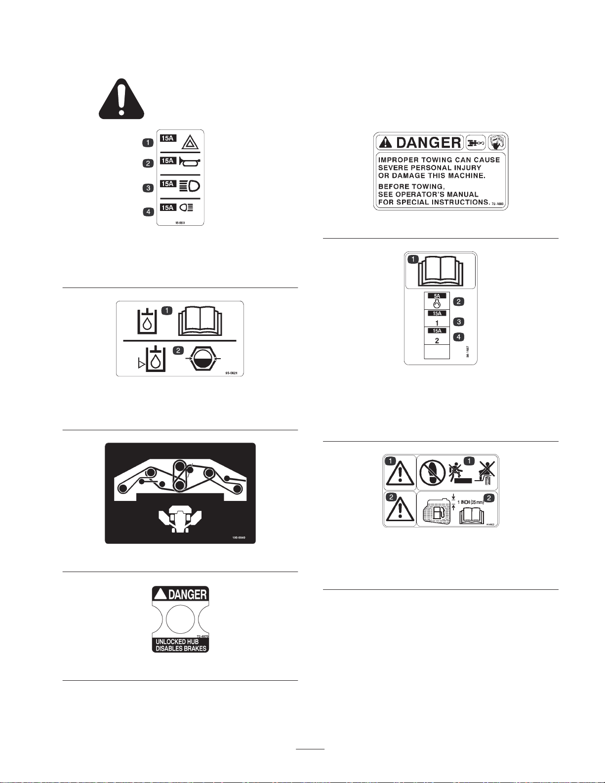
Safety and Instruction Decals
Safety decals and instructions are easily visible to the operator and are located near any area
of potential danger. Replace any decal that is damaged or lost.
95-0831
1. 15 amp. fuse for flasher
2. 15 amp. fuse for horn
3. 15 amp. fuse for
headlights
4. 15 amp. fuse for taillights
72-4080
95-0821
1. Read the operator’s manual for information on hydraulic oil.
2. View the hydraulic level oil through the sight glass.
106-0040
98-1487
1. Read the operator’s manual for further instructions.
2. 5 amp. fuse for controller power
3. 15 amp. fuse for supply one
4. 15 amp. fuse for supply two
95-0822
1. Warning—do not step or ride on fender .
2. Warning—do not fill the fuel tank more than 1 in. (25 mm)
below the bottom of the filler neck.
72-4070
7
Page 8
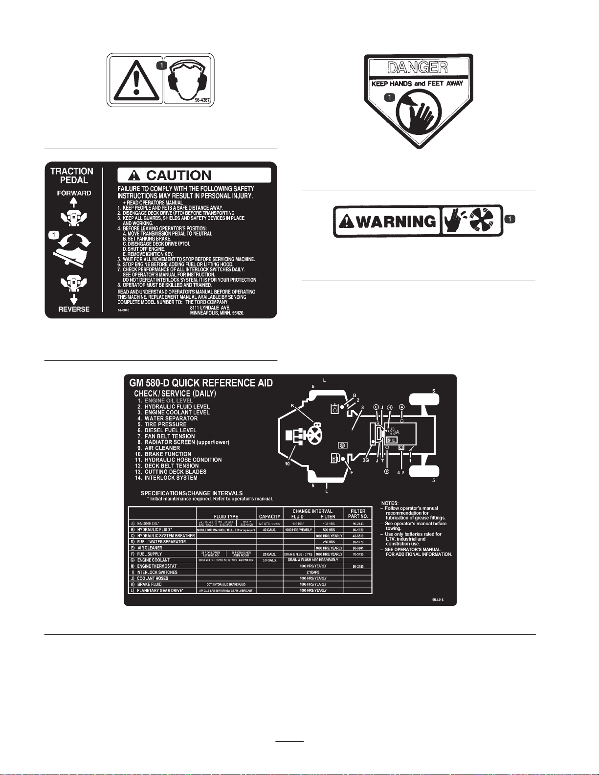
98-4387
1. Warning—wear hearing protection.
69-0940
1. Step on the traction pedal to operate forward or reverse.
43-8480
1. Cutting hazard of hands and fingers
76-8750
1. Cutting hazard of hands and fingers
99–4416
8
Page 9
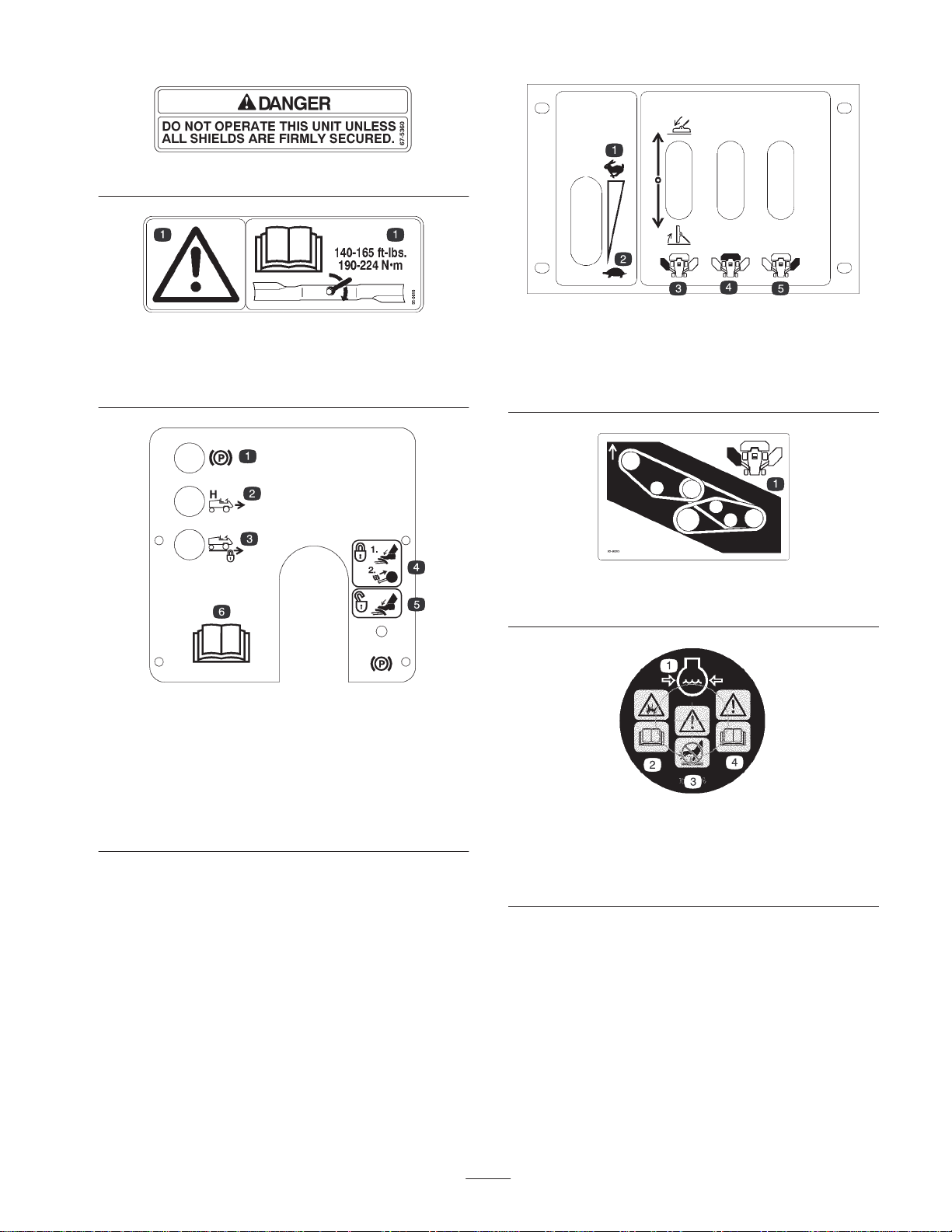
67-5360
95-0818
1. Warning—torque the blade bolt to 140–165 ft.-lb.
(190–224 N⋅m). Read the operator’s manual for further
instructions.
95-0815
1. Throttle fast
2. Throttle slow
3. Raises and lowers the
left-hand cutting unit
4. Raises and lowers the
5. Raises and lowers the
95-0819
1. Belt routing for left-hand cutting unit
front cutting unit
right-hand cutting unit
95-0825
1. Parking brake indictor light
2. High range speed mode indicator light
3. Cruise control indicator light
4. To lock the parking brake, step on the brake pedal while pulling
the parking brake knob out.
5. To unlock the parking brake, step on the brake pedal.
6. Read the operator’s manual for further instructions.
1. Engine coolant under
pressure
2. Explosion hazard—read
Operator’s Manual.
the
106-5976
3. Warning—do not touch
the hot surface.
4. Warning—read the
Operator’s Manual.
9
Page 10
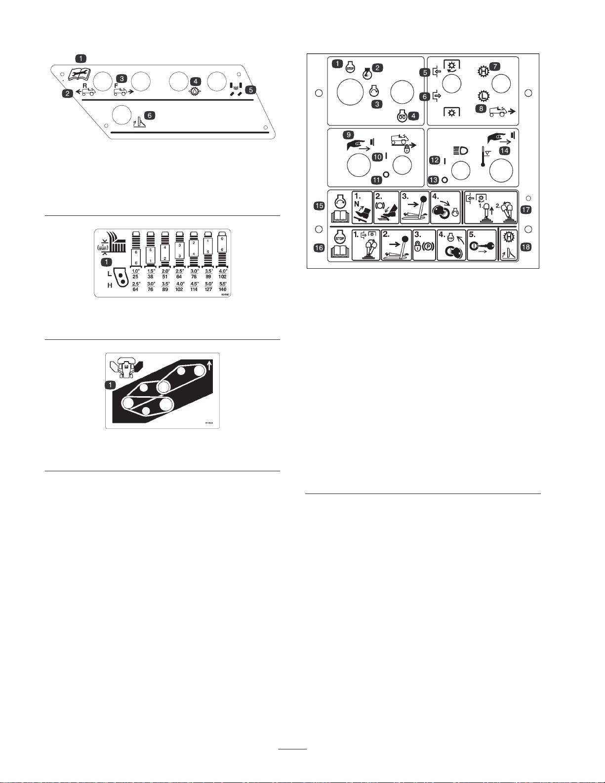
99-1900
1. Read the operator’s
manual for maintenance
procedures.
2. Traction reverse test port
3. Traction forward test port
4. Charge pump test port
5. Steering circuit test port
6. Deck lift test port
95-0845
1. Height-of-cut settings
95-0820
1. Belt routing for right-hand cutting unit
1. Engine stop
2. Engine run
3. Engine start
4. Preheat
5. Engage deck drive
6. Disengage deck drive
7. High range ground speed
8. Low range ground speed
9. Push the button to
engage the cruise control.
10. Cruise control on
11. Cruise control off
12. Headlights on
13. Headlights off
14. Push the button to
over-ride an overheated
engine shutdown.
98-3040
15. To start the engine, keep
your foot off of the traction
pedal, set the parking
brake, put the throttle
lever in Slow, and turn the
ignition switch.
16. To stop the engine,
disengage the deck drive,
put the throttle lever in
Slow, set the parking
brake, turn the ignition
key to Off, and remove
the key from the ignition.
17. To engage deck drive, pull
sleeve upward on switch
lever, push lever to
ENGAGE position and
release to actuate switch.
18. Fully raise cutting units
before operating in HIGH
RANGE ground speed.
10
Page 11
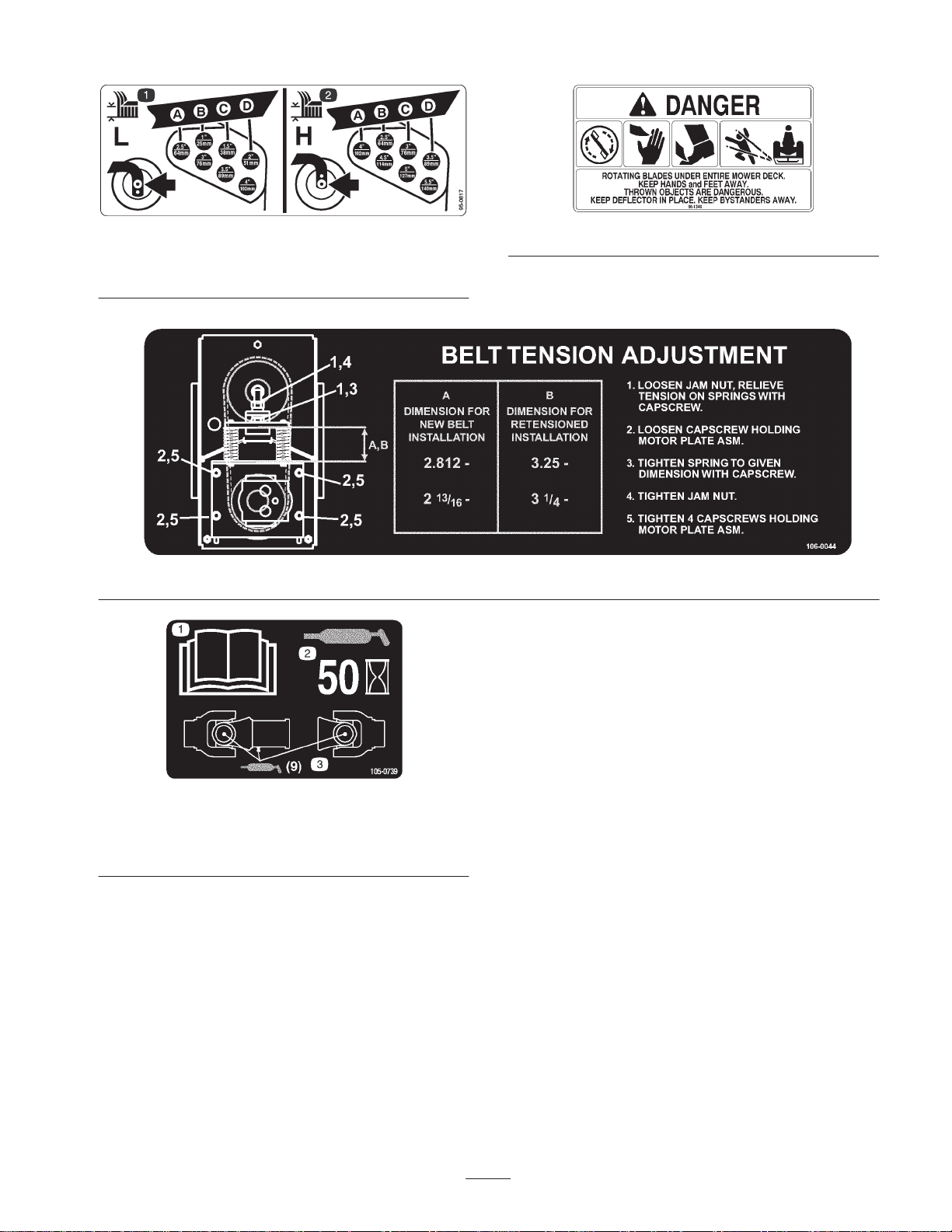
1. Low range height-of-cut
settings
95-0817
66-1340
2. High range height-of-cut
settings
106-0044
1. Read the
Manual.
2. Grease every 50 hours.
Operator’s
105-0739
3. Add grease (9 grease
points).
11
Page 12

Specifications
Note: Specifications and design subject to change without notice.
Traction Unit
Mitsubishi, Model s4s-DT 4 cycle, four cylinder, overhead valve, 203.3 cu. in.
Engine
Air Cleaner Heavy duty, centrifugal air type w/replaceable element
Cooling System
Fuel System Fuel tank capacity: 28 gal. (106 l) of No. 2 diesel fuel
(3331 cc) displacement, water cooled diesel. Rated 80 HP @2750 RPM. 17:1
compression ratio, direct injected and turbo-charged. Crankcase capacity: 8.5 qt.
(8 l).
Radiator w/wide-spaced fins (5 per in.). Variable speed fan controlled by engine
temperature. Full flow hydraulic oil cooler (7 fins/in.). Coolant capacity 3.9 gal.
(14.7 l) of 50/50 mixture of ethylene glycol and water.
Electrical
Controls
Warning Systems
Interlock System
Steering
Seat and Storage
Brakes
12 volt automotive type system. Dual maintenance free batteries w/1300 Amp. cold
cranking power at 0° F (18° C). 50 Amp. alternator with integral regulator.
Individual deck lift levers, High Range/Low Range ground speed selector, PTO and
ignition switches. Hand throttle, ON/OFF cruise control switch and cruise engage
button. Single implement shut-off, steering tower and wheel tilt lever and service
brake pedal. Foot operated traction pedal and steering brake pedals with parking
brake latch.
Indicator lights and audible signals warn of low engine oil pressure, high water
temperature, no charge, water in fuel, low hydraulic oil level, high hydraulic oil
temperature, air cleaner clogged, and hydraulic oil filter needs service.
Indicator lights alone indicate parking brake on, cruise control is engaged, machine
is in High Range ground speed mode.
Prevents engine starting if traction pedal is out of neutral. Stops engine if operator
either leaves seat or parking brake on with traction pedal out of neutral. Prevents
PTO engagement if operator is out of seat, engine is off, or all cutting units are
raised. Prevents engagement of High Range ground speed mode if a cutting unit is
lowered, front cutting unit is not fully raised, or if engine is shut off.
15-1/2 in. (39 cm) patented tilt steering wheel and tower, released and locked by
single control lever. Dual hydraulic cylinder power steering for extra sharp turning.
Deluxe seat w/armrests, backrest, and suspension. Adjustable fore and aft travel,
weight and height. Tool storage tray under hinged floor plate; storage and beverage
holder alongside control panel.
Enclosed, multiple front hydraulic disc brakes operated by right foot pedal.
Mechanical steering brakes via two pedals which lock together for parking brake
function. Dynamic braking through closes-loop hydrostatic drive.
Tires/Wheels
Ground Speed
Ground Clearance 8 in. (20.3 cm)
Hydraulic Oil System and
Reservoir
Front: two 31 x 12.50-15, 8-ply high floatation turf tires w/tubes
Rear: two 23 x 10.5-12, 6-ply tubeless turf tire
Infinitely variable
Forward speeds: Low—0 to 7.5 MPH (12.1 km/h); High—0 to 20 MPH (32.2 km/h)
Reverse speeds: Low—0 to 3 MPH (4.8 km/h); High—0 to 8 MPH (12.9 km/h)
40 gal. (151 l) total system capacity. Reservoir capacity: 32 gal. (121 l).
Replaceable spin-on 5 micron filter element.
12
Page 13

Traction Unit (continued)
Hydrostatic closed loop system driving gear reduction wheel drives. Has bypass
Traction System
valve for towing. Adjustable foot pedal with speed stop controls forward/reverse
ground speed. Switch engaged cruise control, disengaged by service brake or
ON/OFF switch. Cruise speed changeable without disengagement.
All Cutting Units
Cutting Unit Drive System
Automatic Weight Transfer
Cutting Unit Configuration
Mowing Rate/Width
Total Cutting Width 192 in. (488 cm)
Height-of-Cut Range
Blades
Anti-Scalp Devices
All hydraulic drive. Initial cutting drive engagement via electric switch. Drive shuts
off or engaged individually as cutting units are raised or lowered.
Patented automatic weight transfer from decks to traction unit under demanding
traction situations for improved traction and deck floatation
A 92 in. (234 cm) Triflex front center cutting unit and two 57 in. (145 cm) outboard
cutting units
Mows up to 14-1/2 acres/hr (5.9 hectares) at 7.5 MPH (12.1 km/h) using all cutting
units (assumes no overlap and stops)
Low: 1 to 4 in. (2.5 to 10.2 cm)
High: 2-1/2 to 5-1/2 in. (6.3 to 14 cm)
Interchangeable heat treated steel blades, 20 in. (50.8 cm) long, 1/4 in. (6.3 mm)
thick and 2-1/2 in. (6.3 cm) wide. 5 blades on Triflex and 3 each on outboard units.
Cutting units equipped with adjustable skids. Anti-scalp cup on each blade
assembly
Triflex Cutting Unit (Front)
Type
Trimming Ability
Height-of-Cut Adjustment
Cutter Drive
Triflex front mounted rotary cutting unit with 5 blade spindles and 92 in. (234 cm)
width of cut
Trims to either side. 8 in. (20.3 cm) cutting unit offset from outside of wheel to trim
side of front cutting unit on either side.
1/2 in. (12.7 mm) increments by spacers on front castor shafts and clevis pins on
rear wheel forks
Hydraulic gear motor. “BB” hex section belt to center cutting unit spindles, “B”
section belt to wings. Splined shafts, each in two greaseable, tapered roller
bearings in cast iron housings (greaseable from the top). Self tensioning and
permanently lubricated belt idlers.
Castor Wheels Two 10.50 x 3.50 and two 12 x 5.00 heavy duty, pneumatic castor wheels
13
Page 14

Outboard Cutting Units
Type
Trimming Ability
Height-of-Cut Adjustment 1/2 in. (12.7 mm) increments by spacers on all castor shafts
Cutter Drive Hydraulic gear motor. Three “B” section belts to spindles
Castor Wheels Four 10.50 x 3.50 heavy duty, interchangeable, pneumatic castor wheels
Cutting Unit Suspension
Two, three spindle, side mounted rotary cutting units each with a 57 in. (145 cm)
width of cut
Trims to either side. 58 in. (147 cm) cutting unit offset from outside of wheel to trim
side of side cutting unit on either side
Outboard cutting unit arms pivot from center, sweep cutting units forward in mow
and lift, and rotate cutting units down and back in transport. Arms have rubber
mount design for shock absorption and more cutting unit floatation (patented).
Adjustable, spring-loaded, breakaway arms release and rotate outboard cutting unit
upon accidental impact. Automatically reset when cutting unit is raised. Cam lock
links automatically secure outboard cutting units in transport position.
Dimensions
Machine Width (approx.)
Machine Height (approx.)
Machine Overall Length
(approx.)
Total Weight (with fluids)
(approx.)
Transport: 7 ft. 11 in. (241 cm)
Mow: 16 ft. 3 in. (495 cm)
Transport: 7 ft. 7 in. (231 cm) to top of raised cutting units
Mow: 4 ft. 11 in. (152 cm) to top of seat back
14 ft. (427 cm)
6540 lb. (2967 kg)
Optional Equipment
2–Post Roll Over Protection System
Canopy option
Canopy w/ windshield option
Cab with Roll Over Protection System
Road Light Package
8 ft (244 cm) Rotary Broom
Air Conditioning
7 Foot Snow blower
Leaf Mulcher
Cold Start Kit
Foam Filled Castor Tires
Extra Traction Drive Tire
4 Wheel Drive Assist Kit
14
Page 15

Setup
Note: Determine the left and right sides of the machine from the normal operating position.
Description Qty. Use
Deck tilt link
Klik pin
Diagnostic ACE with overlay 1 Troubleshooting aid
Parts Catalog 1 Ordering service parts.
Operator’s manual 2
Operator Video 1
Registration card 1 Fill out and return to Toro. (Shipped in tool box)
Checking the Batteries
1. Unlatch the hood and left hand engine side panel
(Fig. 1). Raise and prop hood open and remove the left
side panel. Make sure hood prop is secured in one of the
mounting brackets on hood.
1
2
Securing the front cutting unit in a vertical
position for service (shipped in the tool box)
Read and understand before operating the
machine.
View and understand before operating the
machine.
Warning
Battery terminals or metal tools could short
against metal tractor components, causing sparks.
Sparks can cause the battery gasses to explode,
resulting in personal injury.
• When removing or installing the battery, do not
allow the battery terminals to touch any metal
parts of the tractor.
• Do not allow metal tools to short between the
battery terminals and metal parts of the tractor.
Figure 1
1. Engine hood
2. Left side panel
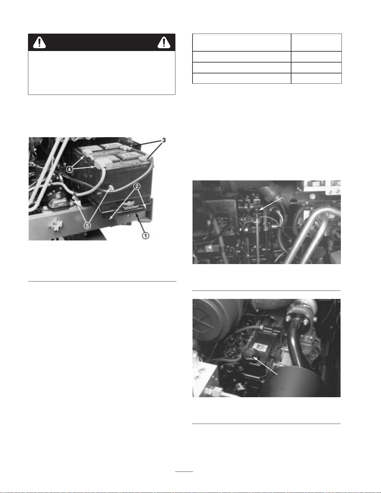
2. Remove the capscrews securing the battery tray and
slide the tray out (Fig. 2).
3. Hood latches
4. Side panel latch
3. Check both batteries for charge with a hydrometer. If
batteries check acceptably, slide tray back in place,
secure with capscrews and lockwashers and install side
panel. If batteries require charging, proceed to step 4.
Warning
Incorrect battery cable routing could damage the
tractor and cables, causing sparks. Sparks can
cause the battery gasses to explode, resulting in
personal injury.
• Always disconnect the negative (black) battery
cable before disconnecting the positive (red)
cable.
• Always reconnect the positive (red) battery cable
before reconnecting the negative (black) cable.
4. Remove negative (–) battery cables from batteries
(Fig. 2). Connect a 3 to 4 Amp battery charger to the
posts. Charge the batteries at a rate of 3 to 4 Amperes
for 4 to 8 hours.
15
Page 16
Warning
Charging the battery produces gasses that can
explode.
Never smoke near the battery and keep sparks and
flames away from the battery.
5. When batteries are fully charged, disconnect charger
from electrical outlet and battery posts.
6. Install negative (–) cable ends, slide tray back in place,
secure with capscrews and install side panel.
Ambient Temperature
–20° to 20° F (–28.9° to –6.7° C) SAE 10
20° to 105° F (–6.7° to 40.6° C) SAE 30
105° F (40.6° C) and higher SAE 40
Note: Do not use multi-viscosity oils.
1. Be sure machine is positioned on a level surface.
2. Unlatch hood and raise and prop it open (Fig. 1). Make
sure hood prop is secured in one of the mounting
brackets on hood.
3. Remove dipstick (Fig. 3), wipe with a clean rag, and
insert into tube until fully seated. Remove dipstick from
tube and check oil level. If oil level is low, remove filler
cap (Fig. 4). Add proper type of oil until level is to top
notch on dipstick. Do not overfill.
1
Proper
Viscosity
Figure 2
1. Battery tray
2. Tray mounting holes
3. Negative (–) connections
4. Positive (+) connections
5. Battery tray mounting
screws
Before Operating
Note: Determine the left and right sides of the machine
from the normal operating position.
Checking the Engine Oil
The engine is shipped with 8.5 qt. (8 l) of oil in the
crankcase. However, check level of oil before and after the
engine is first started.
The engine uses any high quality detergent oil having the
American Petroleum Institute (API) “service classification”
CD. Oil viscosity recommendations are:
Figure 3
1. Dipstick
1
Figure 4
1. Engine oil fill cap
16
Page 17
Important Check oil after every 5 hours operation or
daily. Change oil and filter after the first 50 hours, then
change both every 100 hours operation thereafter. Change
oil and filter more frequently when engine is operated in
extremely dusty or dirty conditions.
4. Insert dipstick into tube and close and latch hood.
Checking the Cooling System
The cooling system is filled with a 50/50 solution of water
and permanent ethylene glycol anti-freeze. Check coolant
level at beginning of each day before starting the engine.
Capacity of cooling system is approximately 3.9 gal.
(14.7 l).
Caution
If the engine has been running, the pressurized,
hot coolant can escape and cause burns.
• Do not open the radiator cap when the engine is
running.
• Use a rag when opening the radiator cap, and
open the cap slowly to allow steam to escape.
Checking the Hydraulic System
Fluid
1. Fluid level should be checked daily through sight glass
at rear of hydraulic reservoir (Fig. 6). When oil is cold,
level will be slightly below center, but should be in the
middle of the sight glass when the oil is warm.
Figure 6
1. Hydraulic oil level sight
glass
2. Reservoir fill cap
1. Unlatch, raise and prop hood open. Make sure hood
prop is secured in one of the mounting brackets on
hood.
2. Remove radiator cap (Fig. 5). Level of coolant must be
above the radiator core and about 1 in. (25 mm) below
bottom of filler neck.
1
Figure 5
1. Radiator cap
3. If coolant level is low, add a 50/50 mixture of water and
ethylene glycol anti–freeze. Do not use
alcohol/methanol base coolants or water only. Do not
overfill.
2. If oil level is low, add hydraulic oil to the reservoir
(Fig. 6); refer to Servicing the Hydraulic System,
page 41.
Filling the Fuel Tank
The engine runs on ASTM No. 2-D diesel fuel.
Danger
Under certain conditions, diesel fuel and fuel
vapors are highly flammable and explosive. A fire
or explosion from fuel can burn you and others
and can cause property damage.
• Use a funnel and fill the fuel tank outdoors, in
an open area, when the engine is off and is cold.
Wipe up any fuel that spills.
• Do not fill the fuel tank completely full. Add fuel
to the fuel tank until the level is 1 in. (25 mm)
below the bottom of the filler neck. This empty
space in the tank allows the fuel to expand.
• Never smoke when handling fuel, and stay away
from an open flame or where fuel fumes may be
ignited by a spark.
• Store fuel in a clean, safety-approved container
and keep the cap in place.
4. Install radiator cap, close and latch the hood.
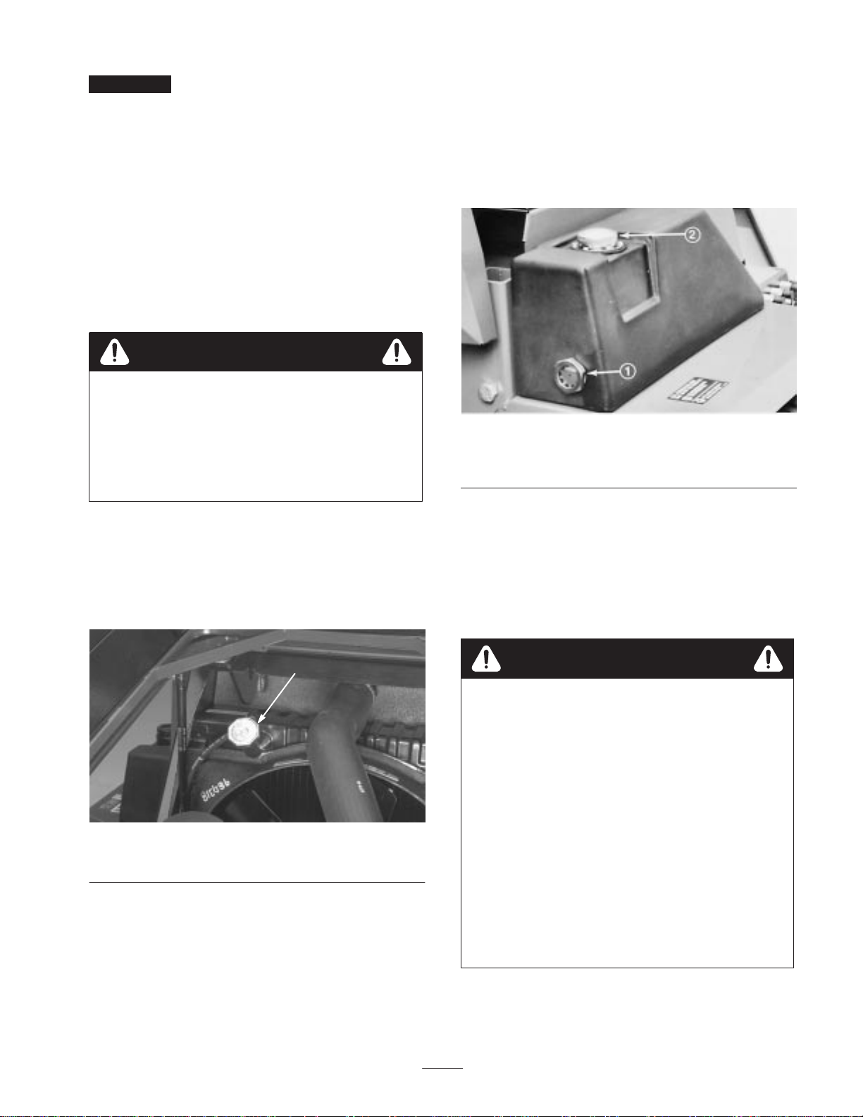
1. Remove fuel tank cap (Fig. 7).
17
Page 18

2. Fill tank to about 1 in. (25 mm) below bottom of filler
neck with No. 2 diesel fuel. Install cap.
Figure 7
1. Fuel tank cap
Checking the Tire Pressure
Since the machine can be operated under many different
types of turf conditions, proper tire pressure is very
important. Use the following as a guide:
• Under Normal mowing conditions and when used on a
wide variety of turf grasses: 15 psi (103.4 kPa) front; 13
psi (89.6 kPa) rear. 50 psi (344.7 kPa) castors.
• When turf is wet and softer than normal, use low
pressure: 12 psi (82.7 kPa) front and 9 psi (62 kPa) rear.
• When turf is dry and harder than normal, use higher tire
pressure: 18 psi (124 kPa) front and rear.
Important Do not operate in HIGH RANGE for
extended periods when tire pressure is less than 18 psi
because tires may be damaged. When tire pressure exceeds
18 psi, HIGH RANGE may be used.
Checking Systems Operation
Start engine. Move the machine, slowly, to an area where
the machine can be checked for proper function. Check
operation of controls, safety interlock system, engine,
hydraulic system, brakes and cutting units; refer to
Operation, page 20, for proper procedures.
Checking Cutting Unit
Mismatch
To ensure all cutting units are at the same height-of-cut:
1. Adjust all cutting units to the highest height–of–cut.
Position all castor arm height-of-cut spacers to on the
underside of the castor arms. Do not move washers.
Leave them in their original position.
Note: Unless all castor wheel axles are not in the same
location, axles do not have to be relocated. All, however
must be in the same holes (Fig. 8).
2. Place a flat 4’x8’ sheet of 3/4 in. plywood on a level
surface and lower a cutting unit onto the plywood.
3. Taking each cutting blade in turn, position blade so it
faces fore and aft. Measure from plywood to front tip of
cutter blade and record dimension. All blade heights on
same deck should be within 1/4 in. (6.3 mm) of one
another. If blade heights meet criteria, proceed to step 5.
If blade heights are not within 1/4 in. (6.3 mm), proceed
to step 4.
4. To match cutting blade height, transfer washers from
one side of a castor wheel arm to the other. If end is to
be lowered, transfer one or both washers from the
underside to the top. By contrast, if end is to be raised,
transfer washer(s) from the top to the underside. Each
washer is 1/8 in. (3 mm) thick. Repeat measurement of
blade tip height and record new dimensions.
5. Repeat steps 2–3 on remaining cutting units, and step 4,
if necessary. If washers are transferred on a outboard
cutting unit castor arm, be sure to transfer the same
number on both ends of the castor arm.
6. Compare blade height dimensions of all cutting units.
Blade heights must be within 3/8 in. (9.5 mm) of one
another. If they are not, determine which cutting unit
height can be changed to compensate for difference and
either transfer washers from bottom to top to lower unit,
or from top to bottom to raise. Transfer an equal
number of washers at all castor wheel locations to keep
cutting unit level—two on front unit, four on outboard
units.
Adjusting the Height of Cut
The height-of-cut is adjustable from 1 to 5-1/2 in. (25 to
140 mm) in 1/2 in. (13 mm) increments. Positioning the
castor wheel axles in the top holes of the castor forks
(Fig. 8) allows Low range height-of-cut settings from 1 to
4 in. (25 to 102 mm); positioning the castor wheel axles in
the lower holes of the castor forks (Fig. 8) allows High
range height-of-cut settings from 2-1/2 to 5-1/2 in. (63.5 to
140 mm).
18
Page 19

Figure 8
1. Start engine, position the machine on a level surface,
lower cutting units to a point where castor wheels can
be removed from arms, set lift levers in neutral, set
parking brake and shut engine off. Remove ignition key
to prevent accidental startup.
2. Position castor wheel axles on all cutting units in the
same hole in the castor forks.
3. On the front cutting unit, remove the hairpin cotter and
clevis pins from the rear castor pivot arms (Fig. 9).
Align the pivot arm holes with selected height–of–cut
bracket holes in the deck frames, insert clevis pins and
install the hairpin cotters (Fig. 9).
Figure 10
1. Lynch pin
2. Spacers
3. Washers
Adjusting the Skids
After initial set up or if height-of-cut is changed, deck skids
should also be adjusted. Adjust skids by loosening flange
lock nuts (Fig. 11), positioning skid at specified height (see
chart) and re-tightening flange lock nuts.
Front Cutting Unit
All H.O.C.—3/8 to 1/2 in. above level surface
Outboard Cutting Units
1 in. H.O.C.—Skid positioned all the way up
1-1/2 to 3 in. H.O.C.—Skid positioned 1/2 to 1 in.
above level surface
3 in. and above H.O.C.—Skid positioned all the way
down
Figure 9
1. Hairpin cotter
2. Clevis pin
3. Castor axle mount holes
4. Pivot arm
4. On all remaining castor wheel assemblies, remove
lynch pin from castor fork shafts (Fig. 10). Remove
castor fork shaft and spacer assembly from the castor
arm (Fig. 10). Place spacers onto castor spindle to
desired height-of-cut setting and install castor fork shaft
in arm (Fig. 9). Install remaining spacers onto shaft and
secure assemblies with the lynch pin (Fig. 10).
Figure 11
1. Skid
19
Page 20

Operation
Note: Determine the left and right sides of the machine
from the normal operating position.
Seat height adjusts vertically to three positions. To raise, lift
seat to first or second click stop; to lower, lift seat to
highest position, then lower to lowest position. Arm rests
pivot up and down.
The use of protective equipment, such as but not limited to,
for eyes, ears, feet, and head is recommended.
Caution
This machine produces sound levels in excess of
85dBA at the operator’s ear and can cause hearing
loss through extended periods of exposure.
Wear hearing protection when operating this
machine.
1
Figure 12
1. Caution 2. Wear hearing protection
2
Controls
Seat
Pull seat adjusting lever (right side) (Fig. 13) outward, slide
seat fore or aft to desired position, and release lever to lock
seat in position. Seat moves 5.9 in. (15 cm) fore and aft in
19/32 in. (15 mm) increments. Knob at lower center
provides infinitely variable weight adjustment from
110–285 lb. (49.9–129.3 kg).
Warning Light Check Switch
Before beginning operation, press the warning light switch
button (Fig. 14). All lights on control panel should light. If
a light fails to illuminate, there is an electrical malfunction
requiring immediate repair.
2 3
1
6
1. Coolant temperature
gauge
2. Fuel gauge
3. Hour meter
4. Coolant temperature
warning
5
4
8
7
Figure 14
5. Engine oil pressure
warning
6. No charge warning
7. Fuel system warning
8. Warning light check
switch
Engine Oil Pressure Warning
Dangerously low engine oil pressure is indicated by both a
warning indicator light (Fig. 14) and audible signal. When
this occurs, stop the engine immediately to keep possible
engine damage minimal.
1. Seat adjusting lever
2. Weight adjusting knob
No Charge Warning
No charge to the batteries is indicated by a warning
indicator light (Fig. 14) and audible signal.
Fuel System Warning
A warning indicator light (Fig. 14) and audible signal warn
of water in the fuel and need for service.
Figure 13
3. Weight indicator
20
Page 21

Coolant Temperature Warning
Hydraulic Oil Level Warning
If engine coolant temperature exceeds 215 F (101.7 C), a
warning indicator light illuminates (Fig. 14) and audible
signal sounds. If coolant temperature exceeds 230 F
(110C), the engine automatically shuts down. Switch
resets automatically when system and engine cools down.
Hour Meter
The hour meter (Fig. 14) registers accumulated hours of
engine operation. Useful for determining intervals for
service maintenance and lubrication.
Coolant Temperature Gauge
The coolant temperature gauge (Fig. 14) indicates
temperature of system coolant.
Fuel Gauge
The fuel gauge (Fig. 14) indicates quantity of fuel in fuel
tank.
Hydraulic Oil Temperature Warning
A warning indicator light (Fig. 15) and audible signal warn
of excessively high hydraulic oil temperature.
A warning indicator light (Fig. 15) and audible signal warn
of low hydraulic oil level. If oil level drops further, the
engine will automatically be stopped. Engine cannot be
restarted until oil supply is brought to a safe level.
Air Cleaner Warning
A warning indicator light (Fig. 15) and audible signal warn
of a clogged air cleaner requiring service. These warnings
alert that the engine has been operated in excess of when
normal filter maintenance should have occurred.
Alarm Silence Button
Pressing button (Fig. 15) silences alarm. Alarm system will
disengage and automatically reset when problem is
corrected.
Parking Brake Indicator
The parking brake indicator, on the steering column
(Fig. 16), alerts operator the parking brake is on.
5
1
2
4
3
Figure 15
1. Hydraulic oil level warning
2. Hydraulic oil temperature
warning
3. Hydraulic oil filter warning
4. Air cleaner warning
5. Alarm silence button
Hydraulic Oil Filter Warning
A warning indicator light (Fig. 15) and audible signal warn
the filter is clogged and in need of service.
Figure 16
1. Parking brake indicator
2. High range speed mode
indicator
3. Cruise control engaged
indicator
4. Parking brake knob
5. Tilt steering control lever
High Range Ground Speed Indicator
The high range ground speed indicator (Fig. 16), on
steering column, alerts operator that the machine is in high
range ground speed mode.
21
Page 22

Cruise Control Indicator
Cruise Control Switches
The cruise control indictor, on steering column (Fig. 16),
alerts operator the cruise control is engaged.
Tilt Steering Control
The tilt steering control is a single lever on right side of
steering column (Fig. 16). Pivot lever rearward to release
and move steering column and tower to desired angle. Pivot
lever forward to lock steering column and wheel in desired
position.
Key Switch
The key switch (Fig. 17) has three positions: OFF, ON, and
START. Rotate key to START and release when engine
begins running. To stop, rotate key to OFF position.
8
2
1
7
3
4
6
3
5
There are two cruise control switches on panel to right of
operator (Fig. 17)—one for ON/OFF control, the other for
cruise engagement. Cruise control operation, when in either
high range or low range mode, is disengaged either by
actuating the brake pedal or turning the switch to OFF
position.
High Range/Low Range Ground Speed
Switch
This single lever (Fig. 17) allows selection of either high or
low range ground speeds. Push switch forward for High
Range or pull back for Low Range. Switch returns to
neutral position. Switch automatically resets to Low Range
when a cutting unit is lowered, front cutting unit is not fully
raised or if engine is shut off.
Cutting Unit Lift Controls
The two outside levers raise and lower the outside cutting
units, the center lever raises and lowers the front unit
(Fig. 17). Engine must be running to lower and raise cutting
units. Cutting unit blades automatically stop whenever the
cutting units are raised. When lowering outside cutting
units, keep control levers actuated until cutting units pass
over center. Units will then “float” down to the turf.
Note: Holding the cutting unit levers in the actuated
position while the units are lowering could drive them
forcefully into the turf and cause cutting unit damage. After
lowering mowers, do not allow levers to snap back to
neutral. This could cause the levers to go past neutral, lock
the cutting units in a non-float mode and prevent them from
following turf contours.
Figure 17
1. Key switch
2. Throttle control
3. Cruise control switches
4. Deck drive/PTO switch
5. Engine override switch
6. High range/Low range
ground speed switch
7. Cutting unit lift controls
8. Glow plug indicator light
Throttle Control
The throttle control (Fig. 17) is used to operate engine at
various speeds. Moving throttle forward increases engine
speed—FAST; rearward decreases engine speed—SLOW.
Glow Plug Indicator
The glow plug indicator (Fig. 17) automatically actuates
proper glow period when ignition key is turned to ON
position. Illuminates when glow plugs are actuated. When
glow plugs are heated sufficiently, light goes off indicating
engine is ready to start.
Deck Drive/PTO Switch
Pull sleeve upward on switch lever (Fig. 17) and push lever
to ENGAGE position and release to actuate switch; lever
will move to neutral position when released. Move lever to
DISENGAGE position to stop. Switch automatically resets
to DISENGAGE when all three cutting units are raised or
engine is shut off.
22
Page 23

Engine Override Switch
If engine has overheated and been shut–down by the safety
switch, depressing button (Fig. 17 and 18) will allow
engine operation. Use button only for emergencies and only
at short intervals.
1
Figure 18
1. Engine override switch
Electrical System—Fuse Block
The electrical system is protected by one 5 Amp and two 15
Amp fuses located under the control panel to the operator’s
right (Fig. 19). A fusible link, located by starter, is
incorporated for the protection of the entire wiring circuit.
The link can be replaced if total loss of electrical function
results. However, the reason for the malfunction should
first be found and corrected.
upon high range/low range ground speed mode(slower in
low than high range) and proportionate to how far pedal is
depressed.
Steering/Parking Brake Pedals
The left and right turn pedals are connected to the front
wheel brakes (Fig. 20). Since both brakes work
independently, they can be used to turn machine more
sharply or to increase traction if one wheel tends to slip
while operating on a hillside. However, wet grass or soft
turf can be damaged when brakes are used for turning. A
brake latch lever locks the two pedals together for parking.
Whenever the engine is shut off, set parking brake to
prevent accidental machine movement. Latch pedals
together, depress them and pull the parking brake knob at
the top of the steering tower up (Fig. 16) Depress brake
pedals to release the parking brake.
2
1
Figure 19
1. Fuse block 2. Fusible link
Traction Pedal
The traction pedal (Fig. 20) controls forward and reverse
operation. Depress top of pedal to move forward and
bottom to move in reverse. Ground speed is dependent
Figure 20
1. Traction pedal
2. Brake pedal
3. Steering/Parking brake
pedals
4. Brake latch lever
Brake Pedal
Single pedal (Fig. 20) operated by the right foot actuates
fully enclosed, multiple disc front brakes.
Note: There is dynamic braking through the closed-loop
hydrostatic traction drive system.
Storage
A large removable tool storage tray is located under a
hinged floor plate (Fig. 21). A small storage and beverage
holder is to the operator’s right.
23
Page 24

7
5
6
4
Figure 21
1. Hinged floor plate 2. Removable tool tray
Important The fuel system must be bled if any of the
following have occurred:
• Initial start-up of a new machine.
• Engine has ceased running due to lack of fuel.
• Maintenance has been performed upon fuel system
components; i.e., filter replaced, separator serviced, etc.
Refer to Bleeding Fuel System.
Starting and Stopping the
Engine
1. Sit on seat, keep foot off traction pedal. Ensure parking
brake is engaged. Set seat and tilt steering wheel and
tower to comfortable position before starting engine.
2. Turn ignition switch to ON position. When glow plug
indicator light goes off, engine is ready to START.
3. Rotate ignition key switch to START position (Fig. 22).
Release key immediately when engine starts and allow
it to return to RUN position.
Note: Do not run starter motor more than 10 seconds at a
time or premature starter failure may result. If engine fails
to start after 10 seconds, turn key to OFF position. Recheck
controls and procedures, wait 10 additional seconds and
repeat starting operation.
2
1. PTO Switch
2. Cruise control switches
3. High/Low range switch
4. Cutting unit lift controls
4. When engine is first started, or after overhaul of the
engine, hydrostatic transmission, steering or wheel
drive, operate machine in forward and reverse for one to
two minutes. Turn steering wheel left and right to check
steering response and operate the lift levers to check for
proper operation. Then, shut engine off, set parking
brake and check for oil leaks, loose parts or other
malfunctions.
1
2
Figure 22
5. Throttle lever
6. Ignition key switch
7. Glow plug indicator light
Caution
Shut engine off and wait for all moving parts to
stop before checking for oil leaks, loose parts, or
other difficulties.
5. Before stopping engine, move HIGH/LOW RANGE
ground speed switch to LOW, disengage PTO and
cruise control switches and move lift levers and traction
pedal to neutral. Move throttle control to SLOW
position. Set parking brake and turn ignition key to OFF
position.
3
24
Page 25

Bleeding the Fuel System
1. Unlatch, raise and prop engine hood open and remove
left side panel (Fig. 23).
Figure 23
1. Engine hood
2. Left side panel
2. At lower left side of engine, loosen air bleed screw at
top of fuel filter/water separator (Fig. 24).
3. Hood latches
4. Side panel latch
1
Figure 25
1. Fuel filter air bleed plug
5. Loosen air vent plug on injection pump about 1-1/2
turns (Fig. 26). Operate priming pump until solid stream
of fuel flows from the vent hole (Fig. 26), then tighten
air vent plug.
6. Push priming pump down to compress spring and rotate
clockwise to lock closed.
7. Try to start engine. If engine starts, install left side
panel, lower hood and resume operation. If engine does
not start, repeat steps 2–7.
Figure 24
1. Fuel filter/water separator
Note: If fuel tank is over half full, gravity will fill the fuel
filter. If tank is less than half full, fill tank.
3. Loosen air vent plug on engine fuel filter assembly
about 1-1/2 turns (Fig. 25).
4. Rotate priming pump (Fig. 226) counterclockwise until
spring in pump assembly releases. Operate pump up and
down until a solid stream of fuel flows out around filter
plug and tighten plug.
2
1
Figure 26
1. Priming pump 2. Injection pump air bleed
plug
Diagnostic Light
The machine is equipped with a diagnostic light which
indicates if the electronic controller is functioning correctly.
The green diagnostic light is located under the control
panel (Fig. 27). When the electronic controller is
functioning correctly and the key switch is moved to the
ON position, the controller diagnostic light will be
illuminated. The light will blink if the controller detects a
malfunction in the electrical system. The light will stop
blinking and automatically reset when the key switch is
turned to the OFF position.
25
Page 26

For the electronic controller to control the machine as
desired, each of the input switches, output solenoids and
relays must be connected and functioning properly.
The Diagnostic ACE display is a tool to help the user verify
correct electrical functions of the machine.
Checking the Interlock
1
Figure 27
1. Electronic controller light
When the controller diagnostic light blinks, one of the
following outputs has been detected in the controller:
• One of the outputs has been shorted.
• One of the outputs is open circuited.
Using the diagnostic display, determine which output is
malfunctioning; refer to Checking the Interlock Switches,
page 26.
If the diagnostic light is not illuminated when the key
switch is in the ON position, this indicates that the
electronic controller is not operating. Possible causes are:
• Loopback is not connected.
• Fuses are blown.
• The light is burned out.
• Not functioning correctly.
• Fusible links are blown.
Check electrical connections, input fuses and diagnostic
light bulb to determine malfunction. Make sure loopback
connector is secured to wire harness connector.
Switches
Caution
If safety interlock switches are disconnected or
damaged the machine could operate unexpectedly,
causing personal injury.
• Do not tamper with the interlock switches.
• Check the operation of the interlock switches
daily and replace any damaged switches before
operating the machine.
• Replace switches every two years regardless of
whether they are operating properly or not.
The purpose of the interlock switches are to prevent the
engine from cranking or starting unless the traction pedal is
in NEUTRAL, to ensure cutting units disengage when
raised or when operator leaves the seat. In addition, the
engine will stop when the traction pedal is depressed with
operator off the seat.
Verifying Interlock Switch Function
1. Park machine on a level surface, lower the cutting units,
stop the engine and engage the parking brake.
2. Open control panel cover. Locate wire harness and
connectors near controller. Carefully unplug loop back
connector from harness connector (Fig. 28).
Note: If the diagnostic light flashes during normal
operation of the machine, do not turn off the machine,
toggle to the output and touch any switch. The LED will
flash indicating the source of the failure.
Diagnostic ACE Display
The machine is equipped with an electronic controller
which controls most machine functions. The controller
determines what function is required for various input
switches (i.e. seat switch, key switch, etc.) and turns on the
outputs to actuate solenoids or relays for the requested
machine function.
1
Figure 28
1. Wire harness and connectors
26
Page 27

3. Connect the Diagnostic ACE display connector
(Fig. 28) to the harness connector. Make sure correct
overlay decal is positioned on Diagnostic ACE display.
Verifying Output Function
1. Park machine on a level surface, lower the cutting units,
stop the engine and engage the parking brake.
2. Open control panel cover. Locate wire harness and
connectors near controller. Carefully unplug loopback
connector from harness connector.
3. Connect the Diagnostic ACE connector to the harness
connector. Make sure correct overlay decal is positioned
on Diagnostic ACE.
4. Turn the key switch to the ON position, but do not start
machine.
Note: The red text on the overlay decal refers to input
switches and the green text refers to outputs.
Figure 29
1. Diagnostic ACE
4. Turn the key switch to the ON position, but do not start
machine.
Note: The red text on the overlay decal refers to input
switches and the green text refers to outputs.
5. The “inputs displayed” LED, on lower right column of
the Diagnostic ACE, should be illuminated. If “outputs
displayed” LED is illuminated, press the toggle button,
on Diagnostic ACE, to change LED to “inputs
displayed”.
6. The Diagnostic ACE will illuminate the LED associated
with each of the inputs when that input switch is closed.
Individually, change each of the switches from open to
closed (i.e., sit on seat, engage traction pedal, etc.), and
note that the appropriate LED on Diagnostic ACE will
blink on and off when corresponding switch is closed
and opened. Repeat on each switch that it is possible to
be changed by hand.
7. If switch is closed and appropriate LED does not blink
on and off, check all wiring and connections to switch
and/or check switches with an ohm meter. Replace any
defective switches and repair any defective wiring.
8. Now start engine and raise and lower each cutting unit.
Note the appropriate LED on the Diagnostic ACE (i.e.
LED is illuminated when cutting unit is lowered and
LED is not illuminated when cutting unit is raised.
The Diagnostic ACE also has the ability to detect which
output solenoids or relays are turned on. This is a quick
way to determine if a machine malfunction is electrical or
hydraulic.
5. The “outputs displayed
Diagnostic ACE, should be illuminated. If “inputs
displayed” LED is illuminated, press the toggle button,
on Diagnostic ACE, to change LED to “outputs
displayed”.
Note: It may be necessary to toggle between “inputs
displayed” and “outputs displayed” several times to do the
following step. To toggle back and forth, press toggle
button once. This may be done as often as required. Do not
hold the button.
6. Sit on the seat and attempt to operate the desired
function of the machine. (If you need help verifying the
correct input settings for each function, refer to the
Logic Chart on page 22) The appropriate output LED’s
should illuminate to indicate that the ECU is turning on
that function. (Refer to the logic chart to be certain of
the specified output LED’s).
Note: If any output LED is blinking, this indicates an
electrical problem with that OUTPUT. Repair / replace
defective electrical parts immediately. To reset a blinking
LED, turn the key switch “OFF”, then back “ON”.
If no output LED’s are blinking, but the correct output
LED’s do not illuminate, verify that all the input switches
work by following the instructions on how to verify
interlock switches. Verify correct switch function.
If the output LED’s are on as specified, but the machine
does not function properly, this indicates a non–electrical
problem. Repair as necessary.
Note: Due to electrical system constraints, the output
LED’s for “START”, “MONITOR” and “ETR/ALT” may
not blink even though an electrical problem may exist for
those functions. If the machine problem appears to be with
one of these functions, be certain to check the electrical
circuit with a volt / ohm meter to verify that no electrical
problem exists to these functions.
If electronic controller experiences an output failure for
either the cruise control or one of the cutting units, the
controller will disable the machine function.
” LED, on lower right column of
27
Page 28

Indications that this is the cause of the problem include:
• Flashing green diagnostic light
• Diagnostic ACE will illuminate the “output fail” LED.
• Diagnostic ACE will flash which output failed.
• Machine will not respond to ignition key inputs.
The above indicates an ECU problem, contact your local
Authorized Toro Distributor for assistance.
If each output switch is in the correct position and
functioning correctly, but the output LED’s are not
correctly illuminated, this indicates an ECU problem. If this
occurs, contact your Toro Distributor for assistance.
Important The Diagnostic ACE display should not be
left connected to the machine. It is not designed to
withstand the environment of the machine’s every day use.
When done using Diagnostic ACE, disconnect it from the
machine and reconnect loopback connector to harness
connector. Machine will not operate without loopback
connector installed on harness. Store Diagnostic ACE in
dry, secure location in shop, not on machine.
28
Page 29

X=CLOSED, O=OPEN, P=OUTPUT ON,
KEY:
M=MOMENTARILY CLOSED,
B= MUST BE CLOSED ONLY IF HI TEMP SWITCH IS CLOSED.
29
LOGIC
GRID
ACTIONS
1) Start
2) Hi Range Engage
3) Run (no operator)
Run (with operator)
4) Cruise Engage
INPUTS
0 Hi Range Disengage
1 Parking Brake (X=OFF)
2 Key Run
X
X
X
X
O
X
3 Traction Neutral
4 Seat Switch
5 High Coolant Temp
6 High Temp Override
X
X
O
B
O
X
X
B
X
7 Cruise Control Enable
8 PTO Engage
9 PTO Disengage
10 Front Deck Down
11 Right Deck Down
O
O O
M
O
12 Left Deck Down
13 Hi Range Engage
14 Hyd. Oil Level (x=ok)
15 Cruise Control Engage
16 Service Brake (x=off)
X
X
M
X
X
/
17
AO Start Key
OUTPUTS
0
1
2 Right Deck Engage
3 Left Deck Engage
4 Gauge Power ON
5 Front Deck Engage
6 Cruise Control Clutch
7 ETR Hold / Alt8 9 Output Fail
P P
P
P
P
10 Harness
11
12 Start
P
13 Hi Range Engage
5) Front Deck Engage
6) Right Deck Engage
7) Left Deck Engage
8) Gauges ON
O
X
O
X
O
X
X
O
X
O
X
X
O
M
O
M
O
M
O
X
O
O
X
X
O
P
P
P
P
Page 30

Checking the Warning
Indicator Lights
Each day, before operating assure all warning lights are
functioning:
1. Sit on seat and apply parking brake. Turn ignition key
ON and push TEST button. All lights should illuminate.
2. If a light fails to illuminate, replace the bulb and test
again.
Pushing or Towing the Machine
In an emergency, the machine can be moved by the
following methods:
• Actuate the bypass valve in the variable displacement
hydraulic pump and push or tow the machine.
• Unlock the front hubs and tow the machine.
Danger
There is no effective braking on the machine when
the wheel hubs are disengaged. Unless it is on a
level surface or the wheels are blocked, the
machine will move freely.
Do not unlock the wheel hubs without either
blocking the wheels or connecting the machine to a
towing vehicle by means of a rigid towing device.
Pump Bypass Method
Use this method for short distances only.
Important Do not push or tow the machine faster than
2–3 mph (3–4.8 km/hr) because internal transmission
damage may occur. The bypass valve must be open
whenever the machine is pushed or towed by this method.
We do not recommend that this process be used as standard
procedure.
Figure 30
1. Bypass valve
Unlocked Hub Method
1. Either block the wheels or connect the machine to a
towing vehicle with a rigid towing device.
Danger
The vehicle will roll with the front wheel hubs
disengaged, and there will be no effective braking.
• Park the vehicle on a level surface or block the
wheels before unlocking the wheel hubs.
• Do not remove the wheel blocks or towing
devices until the wheel hubs are securely locked.
2. Remove bolts securing the disengage covers to both
front wheel hubs.
3. Face the dimpled portion of the disengaged covers
inward and reinstall the covers. Wheel hubs are now
unlocked.
4. Lock the wheel hubs immediately after towing
operations are completed. Remove disengage covers
and reinstall with the dimpled portion facing away from
the wheel hubs.
1. Bypass valve is located in left side of variable
displacement pump (Fig. 30). Rotate the valve 1/2 to 1
turn counterclockwise to open and allow oil to by–pass
internally . Because fluid is bypassed, the machine can
be slowly moved without damaging the transmission.
2. Rotate the valve clockwise until it is securely seated
before starting the engine. However, do not exceed
5–8 ft.-lb. (7–11 N m) torque to close the valve.
Important Running the engine with the bypass valve
open will cause the transmission to overheat.
Operating Characteristics
Familiarization
Before mowing for the first time, practice operating in a
large, open and relatively level area. Start and stop the
engine, operate in forward and reverse in LOW RANGE
ground speed. Practice using the cruise control. Lower and
raise cutting units individually and simultaneously. When
thoroughly familiar with machine functions, practice
operating around trees and obstacles while using the
individual wheel brakes. Also operate up and down slopes
(IN LOW RANGE).
30
Page 31

Note: We recommend HIGH RANGE ground speed be
used for road travel only (with cutting units up).
Points to consider while operating the traction unit, cutting
units or other implements are the hydrostatic transmission,
engine speed, load on the cutting blades or other implement
components and the importance of the brakes. To maintain
adequate power for the traction unit and implement
components while operating, regulate traction pedal
position to keep engine rpm high and relatively constant.
Good rules to follow are; decrease ground speed as the
implement load increases, and increase ground speed as the
load decreases.
Warning Systems
If a warning light and audible warning come on during
operation, stop immediately and correct the problem before
continuing. Serious damage could occur if the machine is
operated with an uncorrected problem. However, if the
engine stops because of overheating, the emergency
over–ride button can be used to operate the engine for short
intervals (Fig. 31).
1
normal configuration. Be sure to inspect the cutting unit for
damage and repair as necessary before resuming operation.
The individual wheel brakes can be used to assist in turning
the machine. However, use them carefully, especially on
soft or wet turf because it may be torn accidentally. The
brakes are also beneficial to maintain traction; for example,
in some slope conditions, the uphill wheel may slip and
lose traction. If this occurs, gradually depress the uphill
brake pedal until the uphill wheel stops slipping, thus
increasing traction on the downhill wheel.
To stop mowing, depress the brake pedal to stop and
disengage the cruise control (if used), move the PTO switch
to DISENGAGE and release (switch returns to neutral),
then fully raise the cutting units.
High Range Ground Speed Operation
We recommend HIGH RANGE ground speed operation be
performed only on roads with the cutting units in fully
raised position. Start the machine in LOW RANGE, then
shift to HIGH RANGE. The HIGH RANGE Indicator light
will turn ON, indicating the machine is in the HIGH
RANGE mode. To cease HIGH RANGE operation, take
foot off traction pedal and apply the brakes. Move throttle
lever to SLOW and position ground speed selector in LOW
RANGE. If the engine begins to labor while climbing an
incline, ease off on the traction pedal and shift to LOW
RANGE. This will prevent overload of the engine and
hydraulic system.
Figure 31
1. Engine override button
Mowing
When approaching area to mow, position the ground speed
selector in LOW RANGE and release. Switch lever will
return to neutral and High Range light will go out. Move
the throttle lever to FAST and lower the cutting units. Pull
the sleeve of the deck drive PTO switch up, position it in
ENGAGE position and release. Lever will return to neutral
position and PTO will be engaged automatically. Depress
traction pedal slowly to begin cutting operation.
Note: After lowering mowers, do not allow levers to snap
back to neutral. This could allow the levers to go past
neutral, lock the cutting units in a non-float mode and
prevent them from following turf contours.
Should either outboard cutting unit contact an immovable
object while mowing, the mower lift arm latch assembly
absorbs the impact and breaks away. This allows the cutting
unit to swing rearward. Should this occur, stop the machine.
Fully raise the cutting unit, then lower it to cutting position.
This will allow the lift arm latch assembly to return to
Caution
• Use extreme care while operating in HIGH
RANGE ground speed selection.
• Watch closely for bystanders, other vehicles and
possible hidden hazards and be prepared to stop
quickly.
Cruise Control Operation
While operating the machine at the desired ground speed,
turn the cruise control switch to ON and press the cruise
control actuating button. The traction pedal will be held in
its position and a constant ground speed will be maintained.
A light on the steering column indicates the cruise control
is in operation. Ground speed can be changed by
over–riding the traction pedal. The pedal will maintain its
new position when the over–riding force is released.
To stop cruise control operation, turn cruise control switch
to OFF position or depress the service brake.
Note: Hold the traction pedal in position when stopping
cruise control operation, otherwise the machine will stop
abruptly due to hydrostatic braking action.
31
Page 32

If it is an emergency and it becomes necessary to stop
suddenly while in cruise control, depress the service brake
pedal, this breaks the electrical circuit, returns the traction
pedal to neutral and stops the machine.
deck lift controls to neutral. Switch cruise control to OFF,
set the parking brake and turn ignition key to OFF. Remove
the key if the machine is to be left unattended.
Stopping the Machine
To stop the machine and cease operation, take foot off
traction pedal and apply the brakes. Move the throttle lever
to SLOW, ground speed selector to LOW RANGE and
Maintenance
Note: Determine the left and right sides of the machine from the normal operating position.
Recommended Maintenance Schedule
Maintenance Service
Interval
After first 10 hours
After first 50 hours
Every 50 hours
Every 100 hours
Every 200 hours
Maintenance Procedure
• Check the fan and alternator belt adjustment.
• Torque the wheel lug nuts.
• Check the cutting unit drive belt adjustment.
• Change the engine oil and replace the filter.
• Replace the hydraulic filter.
• Torque head and adjust valves.
• Check the engine RPM (at idle and full throttle).
• Change the planetary gear drive fluid.
• Lubricate all grease fittings.
• Inspect the air filter, dust cup, and baffle.
• Clean under the cutting unit belt covers.
• Check the cutting unit drive belt adjustment.
• Change the engine oil and replace the filter.
• Check the fan and alternator belt tension.
• Inspect the cooling system hoses.
• Service the air filter.
• Replace the fuel/water separator filter.
• Torque the wheel lug nuts.
Every 400 hours
• Check the battery level and cable connections.
• Replace the hydraulic filter.
• Torque head and adjust valves.
• Check the engine RPM (at idle and full throttle).
32
Page 33

Maintenance Service
Interval
Maintenance Procedure
Every 800 hours
Every 1000 hours or
every 2 years,
whichever occurs first
Important Refer to your engine operator’s manual for additional maintenance procedures.
• Change the planetary gear drive fluid.
• Check the rear wheel toe-in.
• Change the brake fluid.
• Change the fuel filter.
• Change the thermostat.
• Replace the safety switches.
• Flush the cooling system and replace the hoses.
• Drain/flush the fuel tank.
• Change the hydraulic oil.
Caution
If you leave the key in the ignition switch, someone could accidently start the engine and
seriously injure you or other bystanders.
Remove the key from the ignition and disconnect the wire(s) from the spark plug(s) before you
do any maintenance. Set the wire(s) aside so that it does not accidentally contact the spark
plug(s).
33
Page 34

Daily Maintenance Checklist
Duplicate this page for routine use.
For the week of:
Maintenance Check Item
Check safety interlock operation.
Check brake operation.
Check engine oil level.
Check cooling system fluid level.
Drain water/fuel separator.
Check air filter/pre-cleaner condition.
Check radiator and screen for debris.
Check unusual engine noises.
Check unusual operating noises.
Check height of cut.
Check hydraulic system oil level.
Check hydraulic hoses for damage.
Check fluid leaks.
Check tire pressure.
Check instrument operation.
Check condition of blades.
Lubricate all grease fittings.
1
Mon. Tues. Wed. Thurs. Fri. Sat. Sun.
Touch up damaged paint.
1
immediately after every washing, regardless of the interval listed.
Notation for Areas of Concern
Inspection performed by:
Item Date Information
1
2
3
4
5
6
7
8
9
10
11
12
34
Page 35

Lubrication
The following must be lubricated regularly with No. 2
general purpose lithium or molybdenum base grease. The
chart below lists service intervals based upon normal
Component No. of Fittings Service Interval
Center Cutting Unit
1
• Castor fork shaft bushings
2
• Spindle shaft bearings
• Idler pulley bushings
3
• Deck hinge pivot bushings
4
Right and Left-Hand Cutting Units
5
• Castor fork shaft bushings
• Spindle shaft bearings
6
Front Lift Arm Assemblies
7
• Left-hand and right-hand lift arm
• Hydraulic cylinder pivot bushings
8
• Lift arm ball joints
9
Outboard Cutting Unit Lift Assemblies
10
11
12
13
14
15
• Lift arm pivots
• Anti-sway arm bushings
• Lift arm elbow shaft bushings
• Latch ball joints
• Hydraulic cylinder pivot bushings
• Lift clevis pivot bushings
operating conditions. However, lubricate more frequently
under extreme conditions. The left column numbers
correspond with numbers in Fig. 31.
2
5
4
2
8
6
3
4
2
4
2
4
4
4
2
Every 8 hours or daily
Every 50 hours
Every 50 hours
Every 50 hours
Every 8 hours or daily
Every 50 hours
Every 50 hours
Every 50 hours
Every 50 hours
Every 50 hours
Every 50 hours
Every 50 hours
Every 50 hours
Every 50 hours
Every 50 hours
Traction Unit
16
17
18
19
20
21
22
23
24
25 • Rear wheel bearings 2 Repack every 1000 hours
Refer to chart, page 35 and Figure 32 for areas to lubricate and number of fittings involved.
• Steering brake pedal arms
• Engine water pump assembly
• Engine to pump drive yoke
• Rear wheel spindle bushings
• Rear axle pivot bushings
• Steering tie rod ball joint
• Service brake pivot bushings
• Hydraulic steering cylinder ball joints
• Drive shaft
2
1
3
2
1
2
1
2
9
Every 50 hours
Every 50 hours
Every 50 hours
Every 50 hours
Every 50 hours
Every 50 hours
Every 50 hours
Every 50 hours
Every 50 hours
35
Page 36

1
1
2
3
13
3
9
16
8
7
24
14
4
2
5
5
6
15
6
15
5
6
13
10
11
5
12
14
12
2
3
2
9
22
8
7
8
18
14
17
7
13
12
14
12
3
4
2
5
5
6
15
6
6
13
10
11
5
5
21
24
25
19
Engine Oil and Filter
The engine uses any high quality detergent oil having the
American Petroleum Institute – API – “service
classification” CD. Oil viscosity recommendations are:
20
Figure 32
Note: Do not use multi-viscosity oils.
21
23
25
19
Ambient Temperature
Proper
Viscosity
–20° to 20° F (–28.9° to –6.7° C) SAE 10
20° to 105° F (–6.7° to 40.6° C) SAE 30
105° F (40.6° C) and higher SAE 40
36
Page 37

Checking the Oil Level
Check engine oil level after every five hours operation.
1. Unlatch and raise hood and prop it open. Unlatch and
remove left side panel (Fig. 33). Make sure hood prop is
secured in one of the mounting brackets on hood.
1
Figure 35
1. Engine oil fill cap
Changing the Engine Oil and Filter
Figure 33
1. Engine hood
2. Left side panel
3. Hood latches
4. Side panel latch
2. Remove dipstick, wipe with clean rag (Fig. 34) and
fully insert in tube. Remove from tube and check oil
level. Level should be between the marks on the
dipstick. If level is low, remove filler cap (Fig. 35). Add
oil until level is to top mark on dipstick. Do not
overfill.
1
The engine holds approximately 8.5 qt (8 l) of oil. Change
oil and filter after the first 50 hours, then change both every
100 hours operation. However, change oil more frequently
when engine is operated in dusty or sandy conditions. If
possible, run engine just before changing oil because warm
oil flows better and carries more contaminants than cold
oil.
1. Unlatch and raise hood and prop it open (Fig. 33). Make
sure hood prop is secured in one of the mounting
brackets on hood. Unlatch and remove both side panels
(Fig. 33).
2. Place drain pan in line with the drain plug (Fig. 36).
Clean area around drain plug.
1. Dipstick
Figure 34
1
Figure 36
1. Engine oil drain plug
37
Page 38

3. Remove drain plug and allow oil to drain into pan.
Remove and replace oil filter (Fig. 37); refer to parts
catalog for replacement number. Apply a coating of oil
to the filter O-ring and tighten filter by hand.
1
Figure 37
1. Engine oil filter
4. If fuel system becomes contaminated or machine is to
be stored for an extended period, locate drain at bottom
of fuel tank and drain and clean tank. Flush tank with
clean fuel oil.
1
Figure 39
1. Engine fuel filter
Engine Fuel System
1. Locate fuel filter/water separator on lower left side of
engine and drain daily (Fig. 38).
2. Every 200 hours operation, replace filter element of the
fuel filter/water separator.
Figure 38
1. Fuel filter/water separator 2. Water drain plug
3. Every 1000 hours operation, or yearly, replace the
engine fuel filter (Fig. 39)—left front side of
engine—and drain water from the fuel tank. Apply
clean fuel oil to the filter O-ring. Use hands only to
install and tighten filter.
Important Following the maintenance steps listed
above will, under normal conditions, keep the system
trouble-free. However, if the indicator light on the control
panel and audible warning signal activate during operation,
the engine should be stopped and the fuel system serviced
before operation is resumed. This can prevent serious
engine damage from occurring.
Engine Cooling System
The cooling system holds approximately 3.9 gal (14.7 l) of
a 50/50 solution of ethylene glycol anti–freeze and water.
To properly maintain the system, use the following
procedures:
1. Check coolant level each day before starting the engine;
refer to Check Cooling System in Before Operating
section.
Caution
If the engine has been running, the pressurized,
hot coolant can escape and cause burns.
• Do not open the radiator cap when the engine is
running.
• Use a rag when opening the radiator cap, and
open the cap slowly to allow steam to escape.
38
Page 39

2. Each day after operation, clean debris from the radiator
grille. Clean more frequently in dusty and dirty
conditions.
A. Move seat forward as far as possible.
B. Remove upper and lower grille assemblies (Fig. 40).
C. Use compressed air to clean the grilles and remove
debris from grille mounting areas.
D. Install grilles after cleaning, lower and lock seat in
position.
Figure 41
1. Latch handles
2. Radiator cowl
3. Grille support
C. Remove wing nuts securing top of oil cooler to
upper radiator support and pivot top of oil cooler
away from radiator (Fig. 42).
D. Unlatch and raise hood and prop it open. Use
compressed air from the engine fan side to clean the
radiator and oil cooler fins.
Figure 40
1. Upper grille 2. Lower grille
3. Every 100 hours operation, clean the radiator and
hydraulic cooler fins. Clean more frequently in dusty
and dirty conditions.
A. Use procedures in step 2, items A–C.
B. Unlatch latch handles on both sides and remove
radiator cowl and grille support (Fig. 41).
E. Assemble components after cleaning is completed.
Figure 42
1. Oil cooler
2. Radiator
3. Wing nuts
39
Page 40

4. Every 100 hours operation, inspect fan belt for
condition and proper tension. Replace belt if condition
warrants. Check and adjust tension as follows:
A. Unlatch and raise hood and prop it open. Unlatch
and remove right side panel.
B. Proper tension will allow 1/2 in. (13 mm) deflection
when a force of 10 lb. is applied on the belt midway
between the pulleys. If deflection is incorrect,
proceed to step C; if deflection is correct, install
panel and close hood.
C. Loosen the 3 bolts securing alternator to plate and
mounting bracket (Fig. 43). Rotate alternator away
from engine to increase tension and tighten bolts.
Check belt tension after adjustment and re-adjust, if
necessary.
Removing the Filter
1. Release latches securing air cleaner cover to air cleaner
body (Fig. 44). Separate cover from body. Clean inside
of air cleaner cover.
1
2
Figure 44
1. Air cleaner latches 2. Cover
1
Figure 43
1. Alternator
D. Install panel and close hood.
5. Every 100 hours operation, check condition of cooling
system hoses and tightness of connections. Repair, as
needed.
6. Every 1000 hours, or yearly, drain and flush the cooling
system and replace the thermostat and hose assemblies.
Servicing the Air Cleaner
1. Check air cleaner body for damage which could
possibly cause an air leak. Replace a damaged air
cleaner body.
2. Service the air cleaner filter every 200 hours (more
frequently in extreme dusty or dirty conditions).
2. Gently slide filter out of air cleaner body to reduce the
amount of dust dislodged (Fig. 45). Avoid knocking
filter against air cleaner body.
1
Figure 45
1. Air cleaner filter
3. Inspect filter and discard if damaged. Do not wash or
reuse a damaged filter.
40
Page 41

Cleaning the Filter
Multigrade Hydraulic Fluid – ISO VG 68
1. Washing Method:
A. Prepare a solution of filter cleaner and water and
soak filter element about 15 minutes. Refer to
directions on filter cleaner carton for complete
information.
B. After soaking filter for 15 minutes, rinse it with
clear water. Maximum water pressure must not
exceed 40 psi to prevent damage to the filter
element. Rinse filter from clean side to dirty to side.
C. Dry filter element using warm, flowing air (160F
max), or allow element to air-dry. Do not use a light
bulb to dry the filter element because damage could
result.
2. Compressed air method:
A. Blow compressed air from inside to the outside of
dry filter element. Do not exceed 100 psi to prevent
damage to the element.
B. Keep air hose nozzle at least 2 in. from filter and
move nozzle up and down while rotating the filter
element. Inspect for holes and tears by looking
through the filter toward a bright light.
Mobil DTE 26
Amoco Rykon AW No. 68
Chevron Hydraulic Oil AW ISO 68
Conoco Hydroclear AW 68
Exxon Nuto H 68
Pennzoil AW Hydraulic Oil 68
Shell Tellus 68
Texaco Rando HDZ 68
Note: Many hydraulic fluids are almost colorless, making it
difficult to spot leaks. A red dye additive for the hydraulic
system oil is available in 2/3 oz. (20 ml) bottles. One bottle
is sufficient for 4–6 gal (15–22 1) of hydraulic oil. Order
part no. 44–2500 from your authorized Toro distributor.
Not recommended for biodegradable fluid (use food
coloring).
Checking the Oil Level
1. Visually check hydraulic oil level daily through sight
glass (Fig. 46). With machine on a level surface, oil
should be in the middle of the sight glass when warm
and slightly below level when cold.
Installing the Filter
1. Inspect new filter for shipping damage. Check sealing
end of filter. Do not install a damaged filter.
2. Insert new filter properly into air cleaner body. Make
sure filter is sealed properly by applying pressure to
outer rim of filter when installing. Do not press on
flexible center of filter.
3. Install cover and secure latches.
Servicing the Hydraulic System
The machines reservoir is filled at the factory with
approximately 40 gallons of high quality hydraulic fluid.
Check the level of hydraulic fluid before the engine is
first started and daily thereafter. Appropriate hydraulic
oils are listed below.
The following list is not assumed to be all–inclusive.
Hydraulic fluids produced by other manufacturers may be
used if they cross find a cross reference equivalent to the
products listed. Toro will not assume responsibility for
damage caused by improper substitutions, so use only
products from reputable manufacturers who will stand
behind their recommendation.
2. If oil needs to be added, clean area thoroughly around
the fill cap before removing cap (Fig. 46). Add oil until
proper level is indicated in sight glass.
Figure 46
1. Hydraulic oil level sight
glass
2. Reservoir fill cap
41
Page 42

Replacing the Hydraulic Filter
After 50 hours initial operation, replace the hydraulic filter
(Toro Part No. 69–1720). Replace the filter every 500 hours
of operation thereafter.
1. Place drain pan under filter and remove filter (Fig. 47).
Figure 47
1. Hydraulic oil filter
Draining Water from the Hydraulic
Reservoir
Every 500 hours operation, drain water from reservoir at
three (3) locations.
1. Place drain pan under reservoir.
2. Locate plugs at right rear behind front wheel, at rear
center and front center of reservoir (Fig. 48).
2
1
2. Coat O-ring of the replacement filter with clean
hydraulic oil before installing.
3. To tighten filter, hand turn filter element onto filter head
until element is firmly seated against the head.
4. Start engine and check for leaks. Check oil level after
engine has been stopped. Add oil, if necessary.
Inspecting the Lines and Fittings
Every 100 hours operation inspect all hoses, lines and
fittings for signs of leakage or damage (blisters, cut hoses,
etc.)
Warning
Hydraulic fluid escaping under pressure can
penetrate skin and cause injury.
• Make sure all hydraulic fluid hoses and lines are
in good condition and all hydraulic connections
and fittings are tight before applying pressure to
the hydraulic system.
• Keep your body and hands away from pin hole
leaks or nozzles that eject high pressure
hydraulic fluid.
• Use cardboard or paper to find hydraulic leaks.
• Safely relieve all pressure in the hydraulic
system before performing any work on the
hydraulic system.
• Get immediate medical help if fluid is injected
into skin.
Figure 48
1. Drain plug—front center 2. Hydraulic reservoir
3. Open each plug approximately one turn. Allow fluid to
drain until only hydraulic oil is draining and tighten
plug.
4. Check hydraulic oil level. Add oil, as necessary.
Draining the Hydraulic Reservoir
Every 1000 hours operation, or yearly, drain and replace
hydraulic fluid in reservoir. Total system capacity is
approximately 40 gal. (151 l); reservoir capacity is
approximately 32 gal. (121 l).
Note: If oil becomes contaminated (oil appears milky or
black), the system must be flushed. Contact your local Toro
distributor for assistance.
1. Place drain pan under reservoir. In turn, remove all 3
drain plugs and let oil drain into pan (Fig. 48).
2. Inspect O-rings on plugs and replace, if damaged.
Install drain plugs.
3. With machine on level surface, fill reservoir with
hydraulic oil until oil level is midway up in sight glass
(Fig. 46).
4. Install reservoir cap. Start engine and use all hydraulic
controls to distribute oil throughout the system. Check
for leaks. If repairs are needed, shut engine off before
beginning.
42
Page 43

5. Check oil level; add if necessary.
Servicing the Planetary Gear
Hydraulic System Breather
During normal operating conditions, replace the hydraulic
system oil breather every 1000 hours operation, or yearly.
Replace breather more frequently in extremely dusty, dirty
conditions.
1. Release latches, open hood and prop it open with rod.
2. Breather is located along right side of radiator (Fig. 49).
Clean area around it, unscrew it with a wrench and
install replacement.
1
Drive
Change oil initially after 50 hours operation and every 800
hours, or yearly. Use high quality SAE 80–90 wt. gear lube
as replacement. Check oil if leakage is noted.
Checking the Oil Level
1. With machine on level surface, position wheel so the
check/drain plug is at either three or nine o’clock
position (Fig. 51).
Figure 49
1. Hydraulic system breather
3. Close and latch hood.
Hydraulic System Test Ports
The test ports (Fig. 50) are used for testing the hydraulic
circuits. Contact your local Toro distributor for assistance
on use of these components.
1 2 3 4
5
Figure 50
1. Traction—reverse
2. Traction—forward
3. Charge pump
4. Steering control
5. Deck lift
Figure 51
1. Check/drain plug ( 3 or 9 o’clock position)
2. Remove plug. Oil should be to bottom of the hole.
3. Add gear oil, if necessary, to bring up to proper level
and install plug.
4. Repeat steps 1–3 on the opposite gear assembly.
Draining the Gear Oil
1. With machine on level surface, position wheel so the
check/drain plug is at lowest position.
2. Place drain pan under hub, remove plug and allow oil to
drain.
3. When oil has drained, position wheel so plug hole is at
three or nine o’clock position (Fig. 51).
4. Add approximately 32 oz. (1.24 l) high quality SAE
80–90 wt. gear lube to bring level up to bottom of hole
and install plug.
5. Repeat steps 1–4 on the opposite gear assembly.
43
Page 44

Servicing the Battery
Warning
Warning
Battery posts, terminals, and related accessories
contain lead and lead compounds, chemicals
known to the State of California to cause cancer
and reproductive harm. Wash hands after
handling.
Important Before welding on the machine or
performing service to the electrical system, disconnect
negative (–) battery cable from the batteries to prevent
damage to the electrical system.
Check battery cables and connections every 100 hours and
check batteries with a hydrometer every 500 hours
operation. Keep terminals and entire battery case clean.
Clean batteries with a solution of baking soda and water,
then rinse with clear water. To prevent corrosion, coat
battery posts and cable connectors with Grafo 112X
(Skin-over) grease, Toro Part No. 505–47.
1. Unlatch, raise, and prop hood open. Unlatch and
remove left engine side panel.
2. Remove capscrews securing battery tray to machine and
slide tray out (Fig. 52).
Incorrect battery cable routing could damage the
tractor and cables, causing sparks. Sparks can
cause the battery gasses to explode, resulting in
personal injury.
• Always disconnect the negative (black) battery
cable before disconnecting the positive (red)
cable.
• Always reconnect the positive (red) battery cable
before reconnecting the negative (black) cable.
4. Remove negative (–) battery cable connectors from
batteries (Fig. 52). Connect a 3 to 4 amp. battery
charger to the posts. Charge the batteries at a rate of 3 to
4 Amperes for 4 to 8 hours.
Warning
Charging the battery produces gasses that can
explode.
Never smoke near the battery and keep sparks and
flames away from the battery.
Warning
Battery terminals or metal tools could short
against metal tractor components, causing sparks.
Sparks can cause the battery gasses to explode,
resulting in personal injury.
• When removing or installing the battery, do not
allow the battery terminals to touch any metal
parts of the tractor.
• Do not allow metal tools to short between the
battery terminals and metal parts of the tractor.
3. Check both batteries for charge with a hydrometer. If
batteries check acceptably, slide tray back in place,
secure with capscrews and install side panel. If batteries
require charging, proceed to step 4.
Figure 52
1. Battery tray 2. Negative (–) cable
connectors
5. When batteries are fully charged, disconnect charger
from electrical outlet and battery posts.
6. Connect negative (–) cable ends, slide tray back in
place, and secure with capscrews. Install side panel,
close hood and secure both with latches.
44
Page 45

Fuses and Circuit Breaker
One 5 amp., two 15 amp. fuses, and a fusible link are
incorporated for the protection of the entire wiring circuit.
The link can be replaced if total loss of electrical function
results. They are located under the control panel to the right
of the seat (Fig. 53). If total loss of electrical function
occurs, find and correct the malfunction before replacing
the fusible link.
Figure 54
1. Floor plate 2. Tool tray
1
Figure 53
1. Fuse block
Important Do not install fuses in fuse block on left side
of instrument control panel. Fuses should be installed in
this fuse block only if machine is equipped with a road
light kit.
Servicing the Brake System
Check brake fluid level every 50 hours operation. Replace
fluid every 1000 hours operation, or yearly. Replenish
system with DOT 3 hydraulic brake fluid. To check fluid
level:
1. Raise floor panel in front of seat (Fig. 54). Remove tool
tray.
2. Snap cover bail off cover and remove cover from
master cylinder (Fig. 55).
Figure 55
1. Master cylinder
2. Cover bail
3. Reservoir cover
Wheels and Tires
Torque Wheel Nuts
After the first ten (10) hours operation, check torque on the
wheel nuts and every 200 hours thereafter.
1. Torque lug nuts for front wheels 60–70 ft.-lb.
(81–95 N⋅m).
2. Torque lug nuts for rear wheels to 30–35 ft.-lb.
(41–47 N⋅m).
45
Page 46

Checking the Tire Pressure
Since the machine can be operated under many different
types of turf conditions, proper tire pressure is very
important. Check tire condition and pressure daily and use
the following guide to maintain maximum turf conditions:
• Under Normal mowing conditions and when used on a
wide variety of turf grasses—15 psi (103.4 kPa) front;
13 psi (89.6 kPa) rear, 50 psi (344.7 kPa) Casters.
• When turf is wet and softer than normal, use low tire
pressure: 12 psi (82.7 kPa) front and 9 psi (62 kPa) rear.
• When turf is dry and harder than normal, use high
pressure: 18 psi (124 kPa) front and rear.
Important Do not operate in HIGH RANGE for
extended periods when tire pressure is less than 20 psi
(138 kPa) because tires may be damaged. When tire
pressure exceeds 20 psi (138 kPa), HIGH RANGE may be
used.
Cutting Unit Lubrication
Follow guidelines in the Lubrication Chart to properly
maintain the units. To gain access to the center and inner
spindle shaft fittings on each outboard unit, proceed as
follows:
Note: To grease spindle bearings, apply 2–3 pumps with a
hand grease gun for each spindle.
3. Use belt to rotate inner and center spindle pulleys until
grease fittings can be accessed with a grease gun.
4. Grease fittings and replace cover.
Blade Maintenance
Note: Although not needed for normal maintenance
procedures, the front cutting unit can be pivoted (tilted) to a
fully upright position (Fig. 57). Should you desire to tilt the
cutting unit, proceed as follows:
Figure 57
1. Position machine on level surface, lower cutting units to
shop floor, engage parking brake, shut engine off and
remove key from ignition switch.
2. Remove the inner deck pulley cover (Fig. 56).
Figure 56
1. Inner cover
Tilting the Cutting Unit Upright
1. Position front cutting unit so rear castor wheels just
clear the floor, set parking brake and shut engine off.
2. Remove deck tilt link from tool box under traction unit
floor (Fig. 54) and klik pins from weldments on traction
unit frame and cutting unit lift arm.
3. Remove hairpin cotters and clevis pins from the (2) rear
castor assemblies (Fig. 58). Set the left hand clevis pin
aside and insert the right hand clevis pin into the most
forward holes in the castor wheel arm on the right side
of the unit (Fig. 59). The castor arm and pin should be
resting on top of the unit.
46
Page 47

GRAPHIC #
Caution
Personal injury may occur if only one person tries
to pivot the cutting unit up or down.
• Use at least one other person to assist in lifting
or lowering the unit.
• Always use proper lifting techniques and hold
the unit securely when pivoting it up or down.
To Pivot the Cutting Unit Down into the
Operating Position
Figure 58
1. Rear castor wheel
assembly
4. Sit on seat, start the engine and raise the cutting unit to
the full up position so the spring latch on the left lift
arm disengages from the cutting unit. Stop the engine
and remove the key from the ignition switch.
5. Fit deck tilt link over weldment on the right side of
traction unit and secure with klik pin. Position link so it
clears when cutting unit is raised. Keep remaining klik
pin handy to secure opposite end of link to cutting unit
arm weldment (Fig. 59).
2. Hairpin cotter
3. Clevis pin
1. With the help of an assistant, hold the unit upright,
remove the klik pin securing the link end and remove
link end from the weldment.
2. Pivot (tilt) the cutting unit downward.
3. Sit on seat, start engine and lower the cutting unit so
castor wheels just clear the floor.
4. Remove the height-of-cut pin from the right castor
wheel arm. Insert it and the left height-of-cut pin in the
proper height-of-cut holes in the castor arms and cutting
unit.
Blade Bolt Torque
Check blade bolt torque daily or after blade strikes a solid
object. However, if solid object causes blade to be damaged
or bent to a degree it is unusable, replace it; refer to
Removing Cutting Unit Blade, below.
1. Raise cutting units to transport position, engage parking
brake, shut engine off and remove key from ignition
switch.
2. Using a torque wrench and rag or thickly padded glove
to hold blade, torque blade bolts on all cutting units to
140–165 ft.-lb. (190–224 N⋅m).
Figure 59
1. Right rear castor wheel
assembly
2. Clevis pin
3. Weldment
6. Use at least one other person to tilt the cutting unit.
Grasp the front of the unit and lift it to an upright
position (Fig. 57).
7. Hold the unit upright, fit link end over pin on cutting
unit lift arm weldment, and secure with klik pin.
4. Deck tilt link
5. Klik pin (2)
6. Cutting unit arm weldment
Removing the Cutting Unit
Blade
Replace the blade if a solid object is hit, the blade is out of
balance or bent. Always use genuine TORO replacement
blades to ensure safety and optimum performance. Never
use blades made by other manufacturers because they could
be dangerous.
1. Raise cutting unit to transport position, engage parking
brake, shut the engine off and remove key from
ignition.
2. Using a rag or thickly padded glove, grasp end of blade.
Remove blade bolt, lockwasher, anti–scalp cup and
blade from spindle assembly (Fig. 60).
47
Page 48

Danger
A worn or damaged blade can break, and a piece
of the blade could be thrown into the operator’s or
bystander’s area, resulting in serious personal
injury or death.
• Inspect the blade periodically for wear or
damage.
• Replace a worn or damaged blade.
Figure 60
1. Cutting blade
2. Blade bolt and lock
washer
3. Anti-scalp cup
4. Carriage bolt and flange
locknut (8)
Figure 61
3. Examine cutting edges of all blades. Sharpen cutting
edges that are dull or nicked. To assure sharpness,
sharpen only the top side of the cutting edge while
maintaining the original cutting angle (Fig. 62). If the
same amount of metal is removed from both cutting
edges, the blade will remain balanced.
SHARPEN AT THIS
ANGLE ONLY
3. When assembling, make sure blade sail is facing up.
Torque the blade bolt to 140–165 ft.-lb. (190–224 N⋅m).
Inspecting and Sharpening the
Blade
1. Raise cutting units to transport position, engage parking
brake, shut engine off and remove key from ignition
switch.
2. Carefully examine cutting ends of the blade, especially
where the flat and sail (curved part) meet (Fig. 61-A).
Since sand and abrasive material can wear the metal
connecting the flat and sail portions, check the blade
before using the machine. If any wear is noticed
(Fig. 61-B), replace the blade; refer to Removing the
Cutting Unit Blade, page 47.
Figure 62
End View
4. To check blade for being straight and parallel, remove
from cutting unit. Lay blade on level surface and check
its ends. Blade ends must be slightly lower than blade
center and cutting edge lower than heel of the blade. If
so, it will produce good quality–of–cut and require
minimal engine power to turn. By contrast, a blade with
ends higher than blade center, or with cutting edge
higher than the blade heel, is warped or bent and must
be replaced.
5. When assembling, make sure blade sail is facing up.
Torque the blade bolt to 140–165 ft.-lb.
48
Page 49

Inspecting and Adjusting the
Cutting Unit Belt Tension
Important After first ten hours of operation, check new
belts for proper tension; thereafter, check tension every 50
hours.
Front Cutting Unit
Note: Belts for wing unit spindles are tensioned by spring
loaded idlers and normally do not require tensioning.
1. Position machine on level surface, lower cutting unit to
shop floor, engage parking brake, stop the engine, and
remove the ignition key.
2. Remove deck covers.
3. Loosen jam nut and relieve tension on springs with
tensioner bolt (Fig. 63).
4
Outboard Cutting Units
1. Remove deck covers. To check belt tension, apply 8 lb.
(35.5 N) force at mid-span of belt and check deflection.
There should be approximately 5/16 in. (7.9 mm)
deflection. If deflection is incorrect, proceed to step 2.
If deflection is correct, proceed to step 3.
2. To tension belts, loosen flange locknut at top of idler
pulley (Fig. 64). Slide pulley against belt until proper
tension is reached. Hold pulley in position and tighten
locknut.
1
2
1
2
2–13/16”– New belt
3–1/4”– Old belt
3
Figure 63
1. Jam nut
2. Tensioner bolt
4. Loosen (4) capscrews securing slide plate to motor
mount (Fig. 63).
5. Tighten tensioner bolt until springs are compressed to
dimension shown in figure 63.
6. Tighten jam nut securing adjustment (Fig. 63).
7. Tighten (4) capscrews securing slide plate to motor
mount (Fig. 63).
3. Slide plate
4. Tensioner bolt
Figure 64
1. Idler pulley flange locknut 2. Drive belts
3. Replace deck covers.
Replacing the Blade Drive
Belts
Position machine on level surface, lower cutting unit to
shop floor, engage parking brake, shut engine off and
remove key from ignition switch.
Front Cutting Unit
Note: To remove center section belt, wing spindle drive
belts must first be removed.
1. Remove deck covers. Lift each wing to release idler
pulley tension and slip belt off pulleys.
2. Loosen jam nut and relieve tension on springs with
tensioner bolt (Fig. 65).
3. Loosen (4) capscrews securing slide plate to motor
mount (Fig. 65).
4. Remove (4) capscrews securing motor mount to deck
(Fig. 65).
Note: Do not loosen adjusting screws.
8. Replace deck covers.
49
Page 50

6. Position motor mount onto deck while routing belt
8
around drive pulley (Fig. 65). Be careful not to bend,
twist, kink or damage flexible hydraulic lines.
7. Tighten (4) capscrews securing motor mount to deck.
8. Check the drive pulley (Fig. 65) height as follows:
6
7
9
1
• Slide the height gauge (Fig. 65) under drive pulley (not
under hub).
• Equally tighten or loosen (3) adjusting screws (Fig. 65)
until bottom of pulley rests on height gauge
(approximately 1–1/2”).
• Tighten nuts to lock adjustment. Remove height gauge.
9
2
9. Tighten tensioner bolt until springs are compressed to
dimension shown in figure 63.
10.Tighten jam nut securing adjustment (Fig. 63).
10
12
4
9
11. Tighten (4) capscrews securing slide plate to motor
mount (Fig. 63).
12.Check idler arm stop screw (Fig. 67). If distance
between idler arm and stop screw is not approximately
.38”, adjust as follows:
• Loosen jam nuts on stop screw.
11
5
• Thread screw in or out until desired distance is attained.
• Tighten jam nuts.
Figure 65
1. Slide plate
2. Motor mount
3. Drive motor
4. Drive pulley
5. Taper lock bushing
6. Compression spring
7. Spring holder
8. Slide bar
9. Adjusting screw
10. Tensioner bolt
11. Height gauge
12. Center deck spindle
5. Replace belt(s) as required. Install on pulleys as shown
in figure 66.
1
2
3
4
Figure 66
1. Top and middle grooves
2. Bottom grooves
3. Top grooves
4. Top and middle grooves
2
1
.38”
Figure 67
1. Idler arm 2. Stop screw
13.Replace deck covers.
Outboard Cutting Units
Note: To remove lower belt, the other two belts must first
be removed.
1. Position machine on level surface, lower cutting unit to
shop floor, engage parking brake, shut engine off and
remove key from ignition switch.
50
Page 51

2. Remove deck covers. Loosen flange locknuts on idler
pulleys and slide pulleys away from belts.
2. Remove deck covers and relieve belt tension on all belts
(Fig. 64).
3. Remove flange head screws securing gearbox plate to
deck. To separate plate and drive motor assembly from
deck, rotate plate end toward traction unit (Fig. 64). Tip
plate, motor and pulley assembly on its side and remove
from deck. Be careful not to bend, twist, kink or
damage flexible hydraulic lines.
4. Remove belt(s). Position new belt(s) in pulleys and
assemble gear box and plate assembly to deck.
5. Adjust belt tension; refer to Inspecting and Adjusting
the Cutting Unit Belt Tension, page 49.
Separating the Cutting Units
from the Traction Unit
Front Cutting Unit
1. Position machine on level surface, lower cutting unit to
shop floor, engage parking brake, shut engine off and
remove key from ignition switch.
2. Remove deck covers.
3. Loosen jam nut and relieve tension on springs with
tensioner bolt (Fig. 63).
3. Remove flange head screws securing gearbox plate to
deck. To separate plate and drive motor assembly from
deck, rotate plate end toward traction unit (Fig. 68). Tip
plate, motor and pulley assembly on its side and remove
from deck. Be careful not to bend, twist, kink or
damage flexible hydraulic lines.
Figure 68
1. Deck cover
2. Gearbox plate
3. Deck pivot shaft
4. Deck clevis
5. Lift bar
4. Loosen (4) capscrews securing slide plate to motor
mount (Fig. 65).
5. Remove (4) capscrews securing motor mount to deck
(Fig. 65).
Note: Do not loosen adjusting screws.
6. Remove motor mount from deck. Be careful not to
bend, twist, kink or damage flexible hydraulic lines.
7. Remove hex head screws and flange locknuts securing
each lift arm to the castor arm and separate from the
arm.
8. Roll the cutting unit away from the traction unit.
9. To re–install cutting unit, assemble in reverse order.
Outboard Cutting Units
1. Position machine on level surface, lower cutting unit to
shop floor, engage parking brake, shut engine off and
remove key from ignition switch.
4. Remove locknut securing deck pivot shaft into deck
clevis and lift bar (Fig. 68).
5. Move the cutting unit away from the machine.
6. To install cutting unit, assemble in reverse order.
Checking and Correcting
Cutting Blade Mismatch
If there is mismatch between the blades, the grass will
appear streaked when it is cut. This can be corrected by
ensuring all blades are straight and cutting on the same
plane.
1. Adjust cutting unit to highest height–of–cut. Position
castor wheel axles in lower castor fork holes (Fig. 69
and 70). If checking front cutting unit, reposition two
rear castor’s clevis pins to highest height–of–cut setting
(Fig. 69). On the front castors, move all castor spacers
to the underside of the castor arms (Fig. 69). To check
51
Page 52

outboard units, move all castor shaft spacers to the
underside of the castor arms and castor wheel axles to
lower castor fork holes.
Figure 69
1. High range height-of-cut 2. Move to highest
height-of-cut setting
2. Place a flat 4 X 8 sheet of plywood at least 3/4 in.
(20 mm) thick down on a level surface and lower the
cutting unit onto the flat surface.
measurements. Maximum difference allowed between
any two adjacent blades is 1/4 in. (6 mm). Maximum
difference allowed between the highest and lowest
blade measurement is 3/8 in. (10 mm). If measurements
do not fit recommended standards, add shims between
the cutting deck and spindle housing; proceed to step 6.
If measurements meet standards, proceed to step 5.
5. Rotate blades so tips line up with one another. Tips of
adjacent blades must be within 1/8 in.(3 mm) of each
other. If tips are not within 1/8 in. (3 mm) of one
another, add shims between spindle housing and bottom
of cutter deck; proceed to step 6.
6. Remove locknuts securing spindle housing to deck in
area where shims are to be added. To lower a blade, add
a shim (Part No. 3256–24), to each mounting bolt,
between spindle housing and cutter deck. Repeat step 5.
Continue process until blade tips are within the required
dimensions.
Important Do not exceed three shims at any one hole
location. If more than one shim is added to any one hole
location, install decreased amounts of shims in adjacent
holes.
Figure 70
1. High range height-of-cut
2. Move to underside of
castor arm
3. Castor arm
3. Rotate blade so ends face fore and aft. Measure from
flat surface to front tip of cutting blade and record
dimension. Rotate same blade so opposite end faces
forward and repeat measurement. Difference between
the two measurements must not exceed 1/8 in. (3 mm).
If difference exceeds 1/8 in. (3 mm), the blade is bent.
Replace it. Use same procedures to measure all blades.
Adjusting the Winglet
Stabilizers
If front winglet decks bounce excessively when in
transport, an adjustment to the winglet stabilizers is
required.
1. Park machine on a level surface, engage parking brake,
lower front deck completely to the ground and turn the
engine OFF.
2. Loosen capscrews securing winglet stabilizer brackets
to deck and move brackets outward (Fig. 71).
Figure 71
1. Winglet stabilizer brackets
4. Rotate blade so ends face fore and aft. Measure from
flat surface to front of cutting blade and record
dimension. Repeat process with all blades and compare
3. Start engine and raise front deck completely, then stop
engine.
52
Page 53

4. Move stabilizer brackets inward until rollers contacts
skirt of machine, then tighten capscrews locking
adjustment.
Adjusting Traction Control
Neutral
If machine moves when traction pedal and pump lever are
in neutral position, adjustment is required.
1
3
2
1. Park machine on a level surface, engage parking brake,
raise wing decks completely, lower front deck to the
ground and turn the engine OFF.
2. Actuate pump lever (with foot pedal) to make sure that
foot pedal and linkage operate freely. Correct if
necessary.
3. Put blocks at front and rear of all four wheels.
Disengage the two (2) planetary wheel drives; refer to
Pushing or T owing the Machine, page 30.
Caution
Park the machine on a level surface, block the
wheels, and disengage the planetary wheel drives
before adjusting neutral.
4. With engine OFF, loosen nut on carriage bolt and allow
bearing to locate cam (Fig. 72). Carefully tighten nut on
carriage bolt.
5. Loosen screws to allow neutral device bracket to move;
but not freely (Fig. 72). Adjust neutral device bracket so
that 40+
rotate lever. Tighten screws.
6. Adjust neutral switch; refer to Adjusting the Traction
(Neutral) Switch, page 53.
in.-lb. of torque on control lever just starts to
4
5
Figure 72
1. Screws
2. Neutral device bracket
3. Cam
4. Carriage bolt
5. Bearing
Adjusting the Traction (Neutral)
Switch
1. Make sure traction pedal is in neutral position. Loosen
jam nut on switch adjusting screw (Fig. 73).
2. Rotate adjusting screw toward switch until circuit
through switch is made.
3. Rotate adjusting screw an additional 1 turn. Tighten jam
nut.
2
7. Adjust Traction Control Rod; refer to Adjusting the
Traction Control Rod, page 54.
8. If movement is still evident when traction pedal and
pump lever are in neutral contact your local authorized
Toro Distributor for assistance.
1
Figure 73
1. Traction (neutral) switch 2. Adjusting screw
4. Actuate traction pedal in both FORWARD and
REVERSE to assure that switch “clicks” in both
directions.
53
Page 54

Adjusting the Traction Control
Cylinder Head Bolts
Rod
1. Park machine on a level surface, engage parking brake,
raise wing decks completely, lower front deck to the
ground and turn the engine OFF.
2. Remove cotter pin and slotted nut from ball joint at
traction pedal (Fig. 74). Disconnect ball joint from
traction pedal.
Figure 74
1. Cotter pin and slotted nut
2. Ball joint
3. Jam nut
4. Traction pedal
5. Control rod
Torque initially after 50 operating hours and check every
1000 operating hours or annually thereafter.
Engine Valve Clearance
Adjust initially at 50 operating hours and check every 500
operating hours or annually thereafter.
3. Loosen jam nut and adjust ball joint so that when
control rod is all the way back, front of traction pedal
hits the floor. Tighten jam nut.
4. Connect ball joint to traction pedal. Tighten slotted nut
until ball joint it tight against traction pedal then loosen
nut until next slot aligns with hole in ball joint and
install cotter pin.
54
Page 55

Electrical Schematic
OIL PRESSURE SWITCH
PIN
NO.
1
2
BLUE
AUDIO
ALARM
12V +
AUDIO ALARM
INPUT POWER
FROM CONTROLLER
OIL TEMP. SWITCH
AIR CLEANER
HYD. OIL LOW
VOLTMETER
GROUND
ORANGE
3
YELLOW/RED
4
5
6
GREEN/WHITE
TAN
7
8
PINK
9
10
11
12
WHITE
13
BLACK
14
20
24
241314
19
18
17
21
16
21
16
15
9
4
4
8
3
7
2
6
1
5
10
AUDIO ALARM
ENG. COOLANT TEMP.
OIL FILTER PLUGGED
ENGINE TEMP.
FUEL SENDER
WATER IN FUEL
55
SWITCH
15
16
17
18
19
20
21
22
23
24
BROWN
BROWN/RED
RED/WHITE
GREEN/RED
YELLOW
PURPLE
Page 56

Controller Electrical Schematic
N.O.
C
3
3
1
1
2
1
3
32
2
1
3
C N.O.
N.O.
C
N.C.
G
”DIAGNOSTIC
LIGHT”
RS 232
PORT
CONTROLLER–SOLID STATE
KEY SWITCH
REF TORO P.N. 27–2360
S
S3
J3
B
ACE
P3
L3
K3
A
CAN
CONNECTOR
R
”PARKING
BRAKE ON”
”GLOW PLUGS”
CONNECTION DIAGRAM
B
START
RUN
NEUTRAL SWITCH
B3
B2
M3
LOGIC
L1
A1J1K1
START
X
I
B
M1
RUN
Y
A
HIGH ENGINE WATER TEMP.
SEAT SWITCH
HYDRAULIC OIL LOW
C3
H3
K2
L2
”GROUND SPEED/HI RANGE”
Y
SERVICE BRAKE
HIGH TEMP . OVERRIDE
J2
D3
C2
N1
H1
G1
2–SPEED/HI RANGE
CRUISE ENGAGE
PTO ENGAGE
PTO DISENGAGE
CRUISE CONTROL ON
D2
F1
CRUISE CONTROL SOL
RUN
SOLENOID
1A
E2
E3
E1
H2
LOGIC INPUTS
OUTPUTSPOWER
R2
”CRUISE ENGAGED”
Y
RIGHT DECK DOWN
FRONT DECK DOWN
F2
F3
N3
B1
FRONT DECK SOL
RUN
START
HI RANGE DISENGAGE
HI RANGE ENGAGE
LEFT DECK DOWN
A3
G3
G2
N2
M2
C1
LEFT DECK SOL
RIGHT DECK SOL
START RELAY
REF TORO P.N. 66–8800
PARKING BRAKE
A2
P2
P1
D1
GAUGES
”GLOW INDICATOR”
GLOW RELAY
66–8800
R3
R
B
S
I
TO LIGHTS
(OPTIONAL)
FIELD
A
15A
B+
ALTERNATOR
FUSIBLE LINK
START
G
B+
Y
5A
X
15A
STARTER
FUSIBLE
LINK
+
12 VOLTS
–
BATTERIES
56
Page 57

Hydraulic Schematic
100100
100
285
57
Page 58

58
Page 59

59
Page 60

The Toro General Commercial Products Warranty
A Two-Year Limited Warranty
Conditions and Products Covered
The Toro Company and its affiliate, Toro Warranty Company,
pursuant to an a g r eement between them, jointly warrant your 1996
or newer Toro Commercial Product (“Product”) purchased after
January 1, 1997, to be free from defects in materials or
workmanship for tw o years or 1500 operational hours*, whichever
occurs first. Where a warrantable condition exists, we will repair the
Product at no cost to you including diagnosis, labor, parts, and
transportation. This warranty begins on the date the Product is
delivered to the original retail purchaser.
* Product equipped with hour meter
Instructions for Obtaining Warranty Service
You are responsible for notifying the Commercial Products
Distributor or Authorized Commercial Products Dealer from whom
you purchased the Product as soon as you believe a warrantable
condition exists.
If you need help locating a Commercial Products Distributor or
Authorized Dealer, or if you have questions regarding your
warranty rights or responsibilities, you may contact us at:
Toro Commercial Products Service Department
Toro Warranty Company
8111 Lyndale Avenue South
Bloomington, MN 55420-1196
952-888-8801 or 800-982-2740
E-mail: commercial.service@toro.com
Owner Responsibilities
As the Product owner, you are responsible for required maintenance and adjustments stated in your operator’s manual. Failure
to perform required maintenance and adjustments can be grounds
for disallowing a warranty claim.
Items and Conditions Not Covered
Not all product failures or malfunctions that occur during the
warranty period are defects in materials or workmanship. This
express warranty does not cover the following:
• Product failures which result from the use of non-Toro
replacement parts, or from installation and use of add-on,
modified, or unapproved accessories
• Product failures which result from failure to perform required
maintenance and/or adjustments
• Product failures which result from operating the Product in an
abusive, negligent or reckless manner
• Parts subject to consumption through use unless found to be
defective. Examples of parts which are consumed, or used up,
during normal Product operation include, but are not limited to,
blades, reels, bedknives, tines, spark plugs, castor wheels,
tires, filters, belts, etc.
• Failures caused by outside influence. Items considered to be
outside influence include, but are not limited to, weather,
storage practices, contamination, use of unapproved coolants,
lubricants, additives, or chemicals, etc.
• Normal “wear and tear” items. Normal “wear and tear” includes,
but is not limited to, damage to seats due to wear or abrasion,
worn painted surfaces, scratched decals or windows, etc.
Parts
Parts scheduled for replacement as required maintenance are
warranted for the period of time up to the scheduled replacement
time for that part.
Parts replaced under this warranty become the property of Toro.
T oro will make the final decision whether to repair any existing part
or assembly or replace it. Toro may use factory remanufactured
parts rather than new parts for some warranty repairs.
General Conditions
Repair by an Authorized Toro Distributor or Dealer is your sole
remedy under this warranty.
Neither The Toro Company nor Toro Warranty Company is
liable for indirect, incidental or consequential damages in
connection with t h e use of the Toro Products covered by this
warranty, including any cost or expense of providing substitute equipment or service during reasonable periods of
malfunction or non-use pending completion of repairs under
this warranty. Except for the Emissions warranty referenced
below, if applicable, there is no other express warranty. All
implied warranties of merchantability and fitness for use are
limited to the duration of this express warranty.
Some states do not allow exclusions of incidental or consequential
damages, or limitations on how long an implied warranty lasts, so
the above exclusions and limitations may not apply to you.
This warranty gives you specific legal rights, and you may also
have other rights which vary from state to state.
Note regarding engine warranty: The Emissions Control System
on your Product may be covered by a separate warranty meeting
requirements established by the U.S. Environmental Protection
Agency (EPA) and/or the California Air Resources Board (CARB).
The hour limitations set forth above do not apply to the Emissions
Control System Warranty. Refer to the Engine Emission Control
Warranty Statement printed in your operator’s manual or contained in the engine manufacturer’s documentation for details.
Countries Other than the United States or Canada
Customers who have purchased Toro products exported from the United States or Canada should contact their Toro Distributor (Dealer)
to obtain guarantee policies for your country, province, or state. If for any reason you are dissatisfied with your Distributor’s service or
have difficulty obtaining guarantee information, contact the Toro importer. I f all other remedies fail, you may contact us at Toro Warranty
Company.
Part No. 374-0031 Rev. –
 Loading...