

Page 1
FORM NO. 3318-448 GB Rev A
®
MODEL NO. 30555—60001 & UP
MODEL NO. 30555TE—60001 & UP
OPERATOR’S
MANUAL
52” SIDE DISCHARGE CUTTING DECK
© The TORO Company 1995
Page 2

FOREWORD
FOREWORD
The 62” cutting deck has advanced concepts in engineering, design and safety; and if maintained properly, will give excellent service.
Certain information in this manual is emphasized. DANGER, WARNING and CAUTION identify personal safety related information. IMPORTANT identifies mechanical information demanding special
attention. Be sure to read this directive because it deals with the possibility of damaging a part or parts
of the machine. NOTE identifies general information worthy of special attention.
Table of Contents
Page
PECIFICATIONS 6
BEFORE OPERATING 11
Adjusting Height-of-Cut 11
Adjusting The rollers 11
Adjust Skid 11
Check Lubricant In The gear Box 11
OPERATING INSTRUCTIONS 12
Grass Deflector 12
Tension Spring Adjustment 12
LUBRICATION 13
Grease Bearings And Bushings 13
MAINTENANCE 14-21
Trouble Shooting 14
Separating Cutting Unit From The traction Unit 15
PTO Shaft Removal 15
Servicing Bushings in The castor Arms 15
Servicing The castor Wheel and Bearing 16
Checking for Bent Blade 16
Replacing Cutter Blade 17
Checking Sail and Sharpening Cutter Blade 17
Correcting Cutting Unit Mismatch 18
Replacing Grass Deflector 19
Adjusting Cover Latches 19
Adjusting Idler Pulley 19
Replacing Drive Belt 19
IDENTIFICATION AND ORDERING 22
MAINTENANCE CHART 22-23
2
Page 3

Safety
Training
1. Read the instructions carefully. Be familiar with the
controls and the proper use of the equipment.
2. Never allow children or people unfamiliar with these
instructions to use the lawnmower. Local regulations
may restrict the age of the operator.
3. Never mow while people, especially children, or pets
are nearby.
4. Keep in mind that the operator or user is responsible
for accidents or hazards occurring to other people or
their property.
5. Do not carry passengers.
6. All drivers should seek and obtain professional and
practical instruction. Such instruction should emphasize:
• the need for care and concentration when working with ride-on machines;
• control of a ride on machine sliding on a slope
will not be regained by the application of the
brake. The main reasons for loss of control are:
– insufficient wheel grip;
– being driven too fast;
3. WARNING—Petrol is highly flammable.
• Store fuel in containers specifically designed for
this purpose.
• Refuel outdoors only and do not smoke while
refueling.
• Add fuel before starting the engine. Never
remove the cap of the fuel tank or add petrol
while the engine is running or when the engine is
hot.
• If petrol is spilled, do not attempt to start the
engine but move the machine away from the are
of spillage and avoid creating any source of ignition until petrol vapors have dissipated.
• Replace all fuel tanks and container caps securely.
4. Replace faulty silencers.
5. Before using, always visually inspect to see that the
blades, blade bolts and cutter assembly are not worn
or damaged. Replace worn or damaged blades and
bolts in sets to preserve balance.
6. On multi-bladed machines, take care as rotating one
blade can cause other blades to rotate.
Operation
– inadequate braking;
– the type of machine is unsuitable for its task;
– lack of awareness of the effects of ground
conditions, especially slopes;
Preparation
1. While mowing, always wear substantial footwear
and long trousers. Do not operate the equipment
when barefoot or wearing open sandals.
2. Thoroughly inspect the area where the equipment is
to be used and remove all objects which may be
thrown by the machine.
1. Do not operate the engine in a confined space where
dangerous carbon monoxide fumes can collect.
2. Mow only in daylight or in good artificial light.
3. Before attempting to start the engine, disengage all
blade attachment clutches and shift into neutral.
4. Do not use on slopes of more than:
• Never mow side hills over 5°
• Never mow uphill over 10°
• Never mow downhill over 15°
5. Remember there is no such thing as a “safe” slope.
3
Page 4

Travel on grass slopes requires particular care. To
guard against overturning:
• do not stop or start suddenly when going up or
downhill;
13. Disengage drive to attachments, stop the engine, and
disconnect the spark plug wire(s)or remove the ignition key
• before cleaning blockages or unclogging chute;
• engage clutch slowly, always keep machine in
gear, especially when travailing downhill;
• machine speeds should be kept low on slopes and
during tight turns;
• stay alert for bumps and hollows and other hidden hazards;
• never mow across the face of the slope, unless
the lawnmower is designed for this purpose.
6. Use care when pulling loads or using heavy equip-
ment.
• Use only approved drawbar hitch points.
• Limit loads to those you can safely control.
• Do not turn sharply. Use care when reversing.
• Use counterweight(s) or wheel weights when
suggested in the instruction handbook .
7. Watch out for traffic when crossing or near road-
ways.
• before checking, cleaning or working on the
lawnmower;
• after striking a foreign object. Inspect the lawnmower for damage and make repairs before
restarting and operating the equipment;
• if the machine starts to vibrate abnormally (check
immediately).
14. Disengage drive to attachments when transporting or
not in use.
15. Stop the engine and disengage drive to attachment
• before refueling;
• before removing the grass catcher;
• before making height adjustment unless adjustment can be made from the operator's position.
16. Reduce the throttle setting during engine runout and,
if the engine is provided with a shutoff valve, turn
the fuel off at the conclusion of mowing.
8. Stop the blades rotating before crossing surfaces
other than grass.
9. When using any attachments, never direct discharge
of material toward bystanders nor allow anyone near
the machine while in operation .
10. Never operate the lawnmower with defective guards,
shields or without safety protective devices in place.
11. Do not change the engine governor settings or over-
speed the engine. Operating the engine at excessive
speeds may increase the hazard of personal injury.
12. Before leaving the operator's position:
• disengage the power take-off and lower the
attachments;
• change into neutral and set the parking brake;
• stop the engine and remove the key.
Maintenance and Storage
1. Keep all nuts, bolts and screws tight to be sure the
equipment is in safe working condition.
2. Never store the equipment with petrol in the tank
inside a building where fumes may reach an open
flame or spark.
3. Allow the engine to cool before storing in any enclo-
sure.
4. To reduce the fire hazard, keep the engine, silencer,
battery compartment and petrol storage area free of
grass, leaves, or excessive grease.
5. Check the grass catcher frequently for wear or dete-
rioration.
6. Replace worn or damaged parts for safety.
4
Page 5

7. If the fuel tank has to be drained, this should be
done outdoors
8. On multi-bladed machines, take care as rotating one
blade can cause other blades to rotate.
9. When machine is to be parked, stored or left unat-
tended, lower the cutting means unless a positive
mechanical lock is used.
5
Page 6
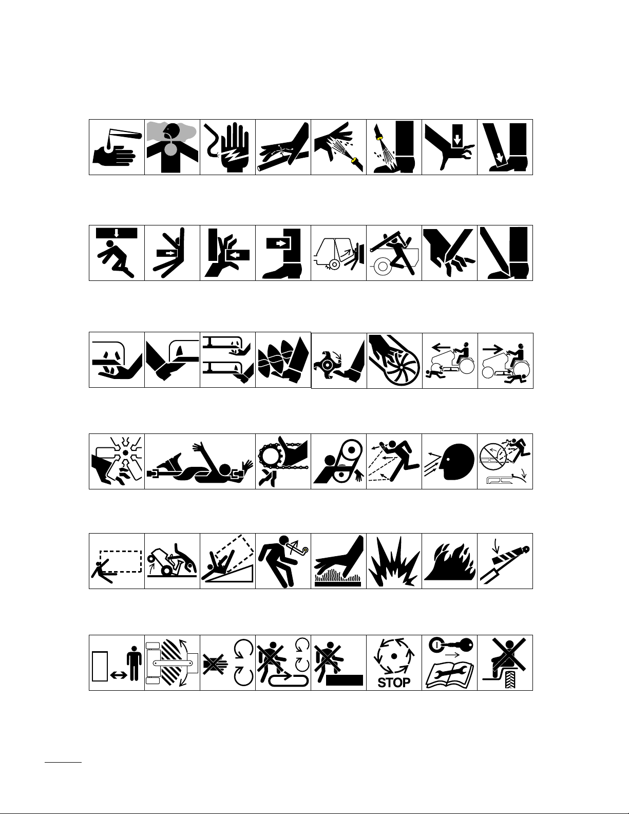
Symbol Glossary
Caustic liquids,
chemical burns to
fingers or hand
Crushing of
whole body,
applied from
above
Severing of
fingers or hand,
mower blade
Poisonous
fumes or toxic
gases, asphyxiation
Crushing of
torso, force
applied from side
Severing of
toes or foot,
mower blade
Electrical shock,
electrocution
Crushing of fingers
or hand/, force
applied from side
Severing of
toes or fingers,
rotary mower
blade
High pressure
fluid, injection
into body
force applied
from side
Cutting or
entanglement of
foot, rotating auger
High pressure
spray, erosion of
flesh
Crushing of
whole body
Severing of
foot, rotating
knives
Crushing of
head, torso and
arms
Severing of
fingers or hand,
impeller blade
High pressure
spray, erosion of
flesh
Crushing of
fingers
force
above
Dismemberment, front engine
mower in forward
motion
or hand,
applied from
Cutting of
fingers or hand
Crushing of
toes or foot, force
applied from above
Cutting of footCrushing of leg,
Dismemberment, front engine
mower in rearward
motion
Severing of
fingers or hand,
engine fan
Runover/backover, vehicle
Stay a safe
distance from
the machine
Whole body entanglement,
implement input drive line
Machine
tipping, riding
mower
Stay clear of
articulation area
while engine is
running
Machine rollover,
ROPS (rear
engine mower)
Do not open
or remove safety
shields while
engine is
running
Fingers or
hand entanglement, chain
drive
Stored energy
hazard, kickback
or upward motion
Do not step on
loading platform
if PTO is connected to tractor &
engine is running
Hand & arm
entanglement,
belt drive
Hot surfaces,
burns to fingers
or hands
Do not step Wait until all
Thrown or flying
objects, whole
body exposure
Explosion Fire or open
machine components have
completely
stopped before
touching them
Thrown or
flying objects,
face exposure
flame
Shut off engine
& remove key
before performing maintenance
or repair work
Thrown or flying
objects, rotary
mover
Secure lifting
cylinder with locking
device before getting
in hazardous area
Riding on this
machine is allowed
only on a passenger seat & only if the
driver’s view is not
hindered
6
Page 7

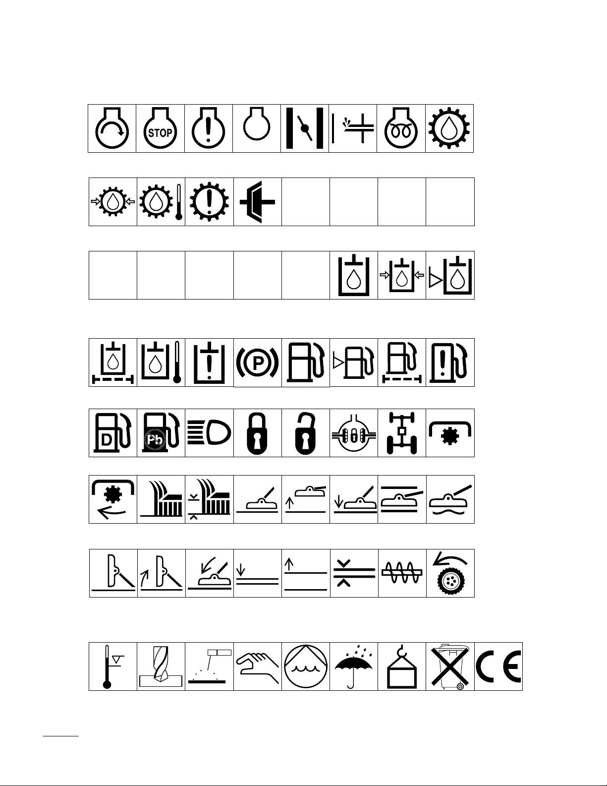
Consult technical
manual for proper
service
procedures
Fasten seat
belts
Safety alert
triangle
Outline safety
alert symbol
Read operator’s
manual
Fire, open light
and smoking
prohibited
Eye protection
must be worn
Head protection
must be worn
Brake system
Filter Temperature Failure/
Plus/increase/
positive polarity
Hearing
protection must
be worn
Oil Coolant (water) Intake air Exhaust gas Pressure Level indicator Liquid level
Minus/decrease/
negative polarity
Caution, toxic
risk
Malfunction
Horn
Flush with water Engine Transmission Hydraulic systemFirst aid
Start switch/
mechanism
Battery charging
condition
Hourmeter/
elapsed operating
hours
On/start Off/stop Engage
Fast Slow Continuous
Disengage
variable, linear
Volume empty Volume full Machine travel
Oil lubrication
point
Engine lubricating
oil temperature
Lift point Jack or
Engine coolant
direction,
forward/
rearward
support point
Engine coolant
pressure
Control lever
operating
direction, dual
direction
Draining/
emptying
Engine coolant
filter
Control lever
operating
direction, multiple
direction
Engine lubricating oil
Engine coolant
temperature
Clockwise
rotation
Engine
lubricating
oil pressure
Engine intake/
combustion air
Counter-clockwise rotation
Engine lubricating
oil level
Engine intake/combustion air pressure
Grease
lubrication
point
Engine lubricating
oil filter
Engine intake/air
filter
7
Page 8
Engine start Engine stop Engine failure/
Transmission
oil pressure
Transmission
oil temperature
malfunction
Transmission
failure/malfunction
RP 231
Reverse
Park First gear
n/min
Engine rotational
speed/frequency
Choke Primer (start aid) Electrical preheat
(low temperature
start aid)
Transmission
oil
NHLF
Clutch Neutral High Low Forward
Second gear
Third gear (other #'s
may be used until the
maximum # of forward
gears is reached.)
Hydraulic oil
Hydraulic oil
pressure
Hydraulic oil
level
Hydraulic oil
filter
Power Take-Off,
rotational speed
Cutting unit,
transport
position
Hydraulic oil
temperature
Blade cutting
element
Cutting unit,
raise to transport
position
Hydraulic oil
failure/malfunction
Blade cutting
element, height
adjustment
Parking brake Fuel
Lock Unlock Differential lock 4-Wheel drive Power Take-OffDiesel fuel Unleaded fuel Headlights
Cutting unit Cutting unit,
Cutting unit,
lower to transport
position
Attachment
lower
raise
Attachment
raise
Fuel level
Cutting unit,
lower
Spacing distance Snow thrower,
Fuel filter Fuel system
Cutting unit,
hold
collector auger
failure/malfunction
Cutting unit,
float
Traction
Above working
temperature
range
Drilling Manual metal
arc welding
Manual Water pump Keep dry Weight Do not dispose
in the garbage
CE logo
8
Page 9

Specifications
Height of Cut: Adjustable from 1” to 4” (25 to 102 mm) in 1/2”
(13 mm ) increments.
Blade Tip Speed: 15,525 ft/min. @ 3250 engine rpm.
Cutter Blades: Three heat-treated steel blades, each 3/16 in. (4.8
mm) thick and 18” (45 mm) long.
Pneumatic Wheels: 8 in. (203 mm) dia. with greaseable roller
bearings. (Inflation 20-30 P.S.I.)
Unit Drive System: PTO driven gear box transmits power through
a “AA” section belt to all blade spindles.
Before Operating
ADJUSTING HEIGHT-OF-CUT
The height-of-cut is adjustable from 25 to 102 mm in 13 mm increments by relocating four clevis pins in different hole locations to
prevent any operating of the cutting unit.
Note: All four pins should be in identical hole locations to prevent
any operating and cutting difficulties.
ADJUSTING THE ROLLERS
Note: If the cutting unit is to be used in 25 mm or 38 mm height-ofcut setting, the internal and external rear cutting unit rollers must be
repositioned in the top bracket holes.
1. Remove the cotter pins securing the roller shafts to the under-
side of the deck (Fig. 2).
2. Slide the shafts out of lower bracket holes, align the rollers
with top holes and install the shafts.
3. Install the cotter pins to secure the assemblies.
1. 25 mm 6 89 mm
Figure 1
2. 38 mm 7. 102 mm
3. 51 mm 8. Grass deflector
4. 64 mm 9. Spring hinges
5. 76 mm
9
Page 10

CHECK THE LUBRICANT IN THE GEAR
BOX
The gearbox is designed to operate on SAE 80-90 wt. gear lube.
Although the gear box is shipped with lubricant from the factory,
check the level before operating the cutting unit.
1. Position the machine and cutting unit on a level surface.
2. Remove the check plug from the side of the gear box and make
sure lubricant is up to bottom of the hole (Fig. 2). If the level
of lubricant is low, remove the fill plug on top of the gear case
and add enough lubricant to bring it up to bottom of the hole in
the side.
1. Filler plug
2. Check plug
3. Drain Plug
Figure 2
10
Page 11

Operating Instructions
GRASS DEFLECTOR
WARNING
The grass deflector is a safety device that diverts grass and other
foreign objects being discharged downward. WE STRONGLY
RECOMMEND THAT THE DEFLECTOR BE IN ITS NORMAL
OPERATING POSITION WHENEVER THE CUTTING UNIT IS
ENGAGED. NEVER OPERATE THE CUTTING UNIT WITH
THE DEFLECTOR REMOVED FROM THE CUTTING UNIT
OR WITH IT ITED/BLOCKED IN A RAISED POSITION. IF
YOU DO, THE BLADES COULD THEN THROW DEBRIS A
CONSIDERABLE DISTANCE WITH SUFFICIENT FORCE TO
CAUSE PERSONAL INJURY OR DAMAGE PROPERTY. If the
grass deflector is damaged, repair or replace the affected parts.
Note: The deflector is spring loaded into its downward normal
operating position but the operator can temporarily swing it out of
the way to facilitate loading in a trailer or other manuevers.
TENSION SPRING ADJUSTMENT
For best performance, adjust spring tension so cutting unit bounce
on uneven turf is minimal and the deck does not ride heavily over
flat terrain. If scalping occurs or the cut is uneven from side to side,
there may too much weight on the deck and weight may have to be
transferred to the traction unit: i.e., increased spring tension.
By contrast, if too much weight is transferred to the traction unit,
the deck will bounce excessively and the cut will be uneven. If the
cutting unit does not perform properly, adjust as follows:
1. Stop the machine on a level surface, set the parking brake,
fully raise the cutting unit, turn the ignition key to OFF and
remove the key from the switch.
2. Remove the hair pin cotter from clevis pin securing spring end
to spring cover and remove clevis pin. Align the top spring end
hole with the new hole selected in the spring cover, insert the
clevis pin and secure it with the hairpin cotter.
3. Resume operations. If further adjustments are required, repeat
the procedure.
11
Page 12

CAUTION
Counterbalance spring(s) are in tension when the deck is in the
lowered position. Always raise the deck before adjusting or
removing the springs.
Maintenance
Lubrication
GREASE BEARINGS AND BUSHINGS
The cutting unit must be lubricated regularly. If the machine is operated under normal conditions, lubricate the castor bearings and
bushings with No. 2 general purpose lithium base grease or molybdenum base grease, after every 8 hours of operation or daily,
whichever comes first. All other bearings, bushings and the gear
box must be lubricated after every 50 hours of operation.
1. The cutting unit lubrication points are: castor spindle bushings,
castor wheel bearings and blade spindle bearings.
2. Lower the cutting unit so the castor wheels are on a level sur-
face. Be sure all height-of-cut pins are in the same hole locations. Remove the check plug (Fig. 5) from the side of the gear
box and check the level of lubricant. If the level of lubricant is
low, remove the fill plug on the top of the gear box and add
SAE 80-90 wt. gear lube until the level is up to the bottom of
the check hole.
Figure 4
Figure 5
1. Filler plug
2. Check plug
3. Drain Plug
12
Figure 3
Page 13

TROUBLESHOO TING
OK
Box Shafts
Inspect Gear
Broken
OK
Box Pulley
Inspect Gear
Loose or
OK
Deck Belts
Inspect Cutter
Loose or
Broken
Broken
Replace
Replace
Tighten or
Replace
Tighten or
Inspect P.T.O.
OK
Inspect P.T.O.
Belt
Pulley
Broken
Loose or
Broken
Loose or
Replace
Tighten or
Replace
Tighten or
UNIT WILL NOT CUT OR CUTS POORLY
OK
Bolts
Loose
Inspect Spindle
OK
Blades
Inspect Cutter
Dull or Bent
Retorque
115–149 Nm
Replace
Sharpen or
OK
Shaft
Broken
Inspect P.T.O.
OK
on Engine
Inspect Pulley
Loose or
Output Shaft
Broken
Replace
Replace
13
Page 14

SEPARATING THE CUTTING UNIT FROM
THE TRACTION UNIT
1. Position the machine on a level surface, raise the cutting unit,
engage the parking brake, be sure the traction pedal is in neutral position, PTO lever in OFF position, shut engine OFF and
remove the key from the switch.
CAUTION
Counterbalance springs are in dension when the deck is in its
lowered position. Always raise the deck before adjusting or
removing the springs.
2. Disconnect the counterbalance from the traction unit, remove
the lockpins from the brackets, separate the spring tension
assemblies from the brackets and lay them down on the deck.
Loosely secure the lockpins to the brackets to prevent losing
them (Fig. 6).
3. Lower the cutting unit, remove (4) pins from the height-of-cut
brackets (Fig. 6).
4. Start the engine and raise the cutting unit frame.
5. Stop engine and slide the cutting unit away from the traction
unit and carrier frame, separating male and female sections of
the PTO shaft (Fig. 7).
CAUTION
Do not start the engine and engage the PTO lever when the
PTO shaft is not connected to the gear box on the cutting
unit. If the engine is started and the PTO shaft is allowed to
rotate, serious injury could result.
1. Lockpin
Figure 6
2. Bracket
3. Spring tension assembly
4. Height-of-cut clevis pin
Figure 7
1. Male PTO shaft
2. Female PTO shaft
2
6. The deck carrier frame must be removed if the traction unit
will be used with any other accessory.
PTO SHAFT REMOVAL
1. Jack the left wheel off the floor. Support the axle with a jack
stand to prevent the machine from falling accidentally.
2. Remove (5) wheel nuts and slide the wheel off the axle to
expose the access hole in the side of the chassis (Fig. 8).
14
1. PTO plug
Figure 8
2. Output shaft
Page 15

3. Rotate the PTO shaft to align the hole in the PTO shaft with
the hole in chassis (Fig. 8).
4. Through the access hole in the chassis, drive the roll out of the
PTO shaft and output shaft with pi punch and hammer
(Fig. 8).
5. Loosen or remove bolts and locknuts and remove the PTO
shaft.
6. Reinstall the wheel with (5) wheel nuts previously removed.
Tighten the nuts to 80–109 kPa.
7. Lower the machine and remove jack.
SERVICING BUSHINGS IN THE CASTOR
ARMS
The castor arms have bushings pressed into the top and bottom portion of the tube which, after many hours of operation, will wear. To
check the bushings, move the castor fork back and forth and from
side to-side. If the castor shaft is loose inside the bushings, bushings
are worn and must be replaced.
1. Raise the cutting unit so its wheels are off the floor and block
it so the cannot accidentally fall.
2. Remove the lynch pin and thrust washers from the top of the
castor spindle.
3. Pull the castor spindle out of the mounting tube. Allow the
thrust washers to remain on the bottom of the spindle.
4. Insert the pin punch into the top or bottom of the mounting
tube and drive the bushing out of the tube (Fig. 9). Also drive
the other bushing out of the tube. Clean the inside of the
mounting tube to remove any dirt.
5. Apply grease to the inside and outside of new bushings. Using
a hammer and flat plate, drive the bushings into the mounting
tube.
6. Inspect the castor shaft for wear and replace if damaged.
7. Push the castor shaft through the bushings and the mounting
tube. Slide the spacers onto the shaft and secure them with a
lynch pin.
1. Lynch pin
Figure 9
2. Thrust washers
15
Page 16

IMPORTANT: When bushings are installed, the inside diameter
may collapse slightly, and this may not allow the castor shaft to
be installed. If the castor spindle does not slide through new
bushings and mounting tube, ream both bushings to inside
diameter of 28.6 mm.
SERVICING THE CASTOR WHEEL AND
BEARING
The castor wheel rotates on a high-quality roller bearing and is supported by a spanner bushing. Even after many hours of use, provided that the bearing was kept well-lubricated, bearing wear will be
minimal. However, failure to keep the bearing lubricated will cause
rapid wear. A wobbly castor wheel usually indicates a worn bearing.
1. Remove the locknut from the capscrew holding the castor
wheel assembly between the castor fork. Grasp the castor
wheel and slide the capscrew out of the fork.
Note: Account for (2) thrust washers.
2. Tip the wheel to the side and allow the spanner bushing to fall
out.
1. Bearing retainer
Figure 10
2. Grease fitting
3. Roller bearing
4. Spanner busing
5. Locknut
6. Capscrew
7. Thrust washer
3. Remove one bushing from the wheel hub and allow the bearing
to fall out. Remove the bushing from opposite side of the
wheel hub.
4. Inspect the bearing, spanner bushing and the wheel for wear.
Replace worn, damaged parts.
5. To assemble parts, slide the spanner bushing through the hub
assembly.
6. Mount the castor wheel assembly and washers between the
fork, insert the capscrew and locknut. Tighten the capscrew and
locknut until the spanner bushing and washers bottom against
the inside of the castor fork.
7. Pump grease through the grease fitting on the wheel until the
bearing is greased thoroughly.
CHECKING FOR A BENT BLADE
1. Position the machine on a level surface, raise the cutting unit,
engage the parking brake, be sure the traction pedal is in the
neutral position, the PTO lever in the OFF position, shut off the
engine, remove the key from the switch and disconnect the
16
Page 17

wires from the spark plugs. Block the cutting unit to prevent it
from falling accidentally.
2. Rotate the blade until the ends face forward and backward.
Measure from inside of the cutting unit to the cutting edge at
front of blade (Fig. 11), and remember this dimension.
3. Rotate the opposite end of the blade forward. Measure
between the cutting unit and the cutting edge of blade at the
same position as in step 2. The difference between dimensions
obtained in steps 2 and 3 must not exceed 32 mm. If dimension exceeds 32 mm, replace the blade because it is bent: refer
to Removing Cutter Blade.
REPLACING THE CUTTER BLADE
The blade must be replaced if a solid object is hit, the blade is outof-balance or if the blade is bent. Always use genuine TORO
replacement blades to be sure of safety and optimum performance.
Never use replacement blades made by other manufacturers because
they could be dangerous.
Figure 11
WARNING
Do not try to starighten a blade that is bent, and never weld a broken or cracked blade. Always use a new blade to assure safety.
1. Position the machine on a level surface, raise the cutting unit,
engage the parking brake, be sure the traction pedal is in neutral position, the PTO lever in the OFF position, shut off the
engine, remove the key from the switch and disconnect wires
from spark plugs. Block the cutting unit to prevent it from
falling accidentally.
2. Grasp the end of blade using a cloth or thickly padded glove.
Remove the blade bolt, flatwasher, cup and blade from spindle
shaft.
3. Install the blade-sail facing toward the cutting unit- with the
cup, flatwasher and blade bolt. Tighten the blade bolt to
115–149 Nm
CHECKING THE SAIL AND SHARPENING
THE CUTTER BLADE
1. Blade bolt
Figure 12
2. Flatwasher
3. Cut
Two areas must be considered when checking and servicing the cut-
17
Page 18

ter blade: one area is the sail, the other is the cutting edge. Both
the cutting edges and the sail, which is the turned up portion opposite the cutting edge, contribute to a good quality-of-cut. The sail is
important because it pulls grass up straight, thereby producing an
even cut. However, the sail will gradually wear down during operation, and this condition is normal. As the sail wears down, the
quality-of-cut will degrade somewhat, although the cutting edges
are sharp. The cutting edge of the blade must be sharp so the grass
is cut rather than torn. A dull cutting edge is evident when tips of
the grass appear brown and shredded. Sharpen the cutting edges to
correct this condition.
1. Position the machine on a level surface, raise the cutting unit,
engage the parking brake, be sure the traction pedal is in neutral position, the PTO lever in the OFF position, shut engine
OFF, remove the key from the switch and disconnect wires
from spark plugs. Block the cutting unit to prevent it from
falling accidentally.
A
B
C
1
2
3
4
5
6
2. Examine the cutting ends of the blade carefully, especially
where the flat and curved parts of the blade meet (Fig. 13 A).
Since sand and abrasive material can wear away the metal that
connects the flat and curved parts of the blade, check the
blade before using the mower. If wear is noticed (Fig. 13 B),
replace the blade.
3. Examine the cutting edges of all blades. Sharpen the cutting
edges if they are dull or nicked. Sharpen only the top of the
cutting edge and maintain the original cutting angle to make
sure of sharpness (Fig. 14). The blade will remain balanced if
same amount of metal is removed from both cutting edges.
DANGER
If the blade is allowed to wear, a slot will form
between the sail and the flat part of the blade (Fig. 13
C). Eventually a piece of the blade may break off and
be thrown from under the housing, possibly resulting
in serious injury to yourself or to bystanders.
1. Flat part of blade
Figure 13
2. Sail
3. Sail
4. Wear
5. Wear
6. Slot formed
Figure 14
1. Sharpen at this angle only
Note: Remove the blades and sharpen them on a grinder: refer to
Removing Cutter Blades, steps 2 and 3. After sharpening the cutting edges, reinstall the blade with the cup, flatwasher and blade
bolt. Blade sails must be on top of blade. Tighten the blade bolt to
115–149 Nm.
18
Page 19

CORRECTING CUTTING UNIT MISMATCH
If one cutter blade cuts lower than the others, correct as follows:
1. Lower the cutting unit onto a level surface, engage the parking
brake, be sure the traction pedal is in neutral position, the PTO
lever in the OFF position, shut engine OFF, remove the key
from the switch and disconnect wires from spark plugs. Make
sure tire pressure is equal on all tires.
2. Raise the height-of-cut to the 4 in. position: refer to Adjusting
Height Of Cut.
3. Rotate blades so the tips line up with one another. Tips of the
adjacent blades must be within 3 mm If tips are not within 3
mm of each other, proceed to step 10 and add shims between
spindle housing and bottom of the cutting unit.
4. Check to make sure front height-of-cut pins are resting proper-
ly on frame cushions. If pins are not resting properly, place a
shim or shims under cushion to raise it for proper alignment.
Figure 15
5. Position all three blades in the “A” position (Fig. 15) and mea-
sure from level surface to the bottom of the tip end of each
blade (Fig. 16).
6. Note measurement attained at “A”, rotate blades to the“B”
position (Fig. 14), measure distance of all blades to level surface and note dimensions (Fig. 15).
7. Rotate blades to the “C” position, measure and note distance
measured (Fig. 14, 15).
8. Compare measurements at various positions. All dimensions
must be equal within 6 mm from any two adjacent blades. The
difference between dimensions of all three blades must not
exceed 9.5 mm. If difference exceeds specifications, go to
step 9.
9. Remove the capscrews, flatwashers and locknuts from outer
spindle in the area where shims must be added. To raise or
lower the blade, add a shim, Part No. 3256-24, between spindle
housing and bottom of the cutting unit. Continue checking
alignment of blades and adding shims until tips of blades are
within the required dimension.
1. Measure from blade tip to level surface
Figure 16
10. Equalize side-to-side measurements as follows:
19
Page 20

A. Cutting units usually operated at 25 mm to 50 mm height-
of-cut should have the low side of the cutting unit raised.
Remove the lynch pin securing castor wheel on low end
(Fig. 17) and remove the castor assembly.
B. Transfer one thrust washer from top side of the castor
shaft to lower side, install the castor assembly and compare blade height of all blades; refer to items 3 through 7.
Continue adding thrust washers if height still does not
meet requirements.
C. If the cutting unit is operated at 5–10 cm height-of-cut,
lower the high side of the cutting unit. Remove lynch pin
of the castor at high end of unit and remove the castor
assembly (Fig. 17).
D. Transfer one thrust washer from lower side of the castor
shaft to top side, install assembly and compare blade
height of all blades; refer to items 3 through 7. Repeat
procedure if height still does not meet requirements.
E. If height is within specified dimension, install thelynch
pin, set the height-of-cut and resume operation.
REPLACING THE GRASS DEFLECTOR
1. Highest height-of-cut setting
2. Thrust washers are required
Figure 17
1. Position the machine on a level surface, raise the cutting unit,
engage the parking brake, be sure the traction pedal is in neutral position, the PTO lever in OFF position, shut engine OFF
and remove the key from the switch. Block the cutting unit to
prevent it from falling accidentally.
2. Remove two capscrews, locknuts and springs securing deflec-
tor mounts to pivot brackets.
3. To remove the pivot brackets, remove carriage bolts and nuts.
4. Reinstall pivot brackets on top of discharge opening with car-
riage bolts and nuts. Head of carriage bolts must be on inside
of the cutting unit.
5. Position deflector mounts on pivot brackets and secure parts
together with capscrews, locknuts and springs. Both locknuts
must face each other. Tighten the locknuts until they are flush
against deflector pivots.
6. Lift deflector and allow it to drop to check spring tension.
Deflector must be held firmly in full downward position by
spring tension. Correct if necessary.
1. Capscrew
2. Locknut
3. Spring
4. Pivot brackets
Figure 18
20
Page 21

ADJUSTING THE IDLER PULLEY
The idler pulley applies force against the belt so power can be transmitted to the blade pulleys. If the idler is not tensioned against the
belt with sufficient force, maximum power will not be transmitted
to the pulleys. Tension on the belt requires 54 to 68 Nm of torque
on the large nut, which applies force against the belt If the idler is
not adjusted to these specifications, adjustment is necessary.
1. Position the machine on a level surface, lower the cutting unit,
engage the parking brake, be sure the traction pedal is in neutral position, the PTO lever in OFF position, shut engine OFF
and remove the key from the switch.
2. Release and unhook latches securing center cover to top of the
cutting unit. Remove cover from the cutting unit.
3. Loosen two nuts securing idler plate in place. Using a socket
and torque wrench, tighten the idler adjusting nut to 47 Nm.
4. Hold the torque against the belt and tighten the two nuts so
idler plate is held securely in place. Release the idler adjusting
nut. Install the cover and secure the latches.
REPLACING THE DRIVE BEL T
The blade drive belt, tensioned by the adjustable idler, is very
durable. However, after many hours of use, the belt will show signs
of wear. Signs of a worn belt are: squealing when the belt is rotating, blades slipping when cutting grass, frayed edges, burn marks
and cracks. Replace the belt if any of these conditions are evident.
1. Position the machine on a level surface, lower the cutting unit,
engage the parking brake, be sure the traction pedal is in neutral position, the PTO lever in the OFF position, shut off the
engine and remove the key from the switch.
2. Release and unhook the latches securing the covers to the top
of the cutting unit. Remove the covers.
3. Loosen the two nuts securing the idler plate in place and
remove the old belt fromthe pulleys.
4. To install a new belt, the gear box base must be removed. To
do this, remove the four carriage bolts and locknuts holding the
gear box base.
1. Idler adjusting nut
Figure 19
2. Nuts (2)
3. Idler plate
5. Install the new belt around the gear box pulley, spindle pulleys,
21
Page 22

stationary idler pulley and adjustable idler pulley.
6. Install the gear box base with carriage bolts and locknuts.
7. Using a torque wrench, adjust the tension of idler pulley
against the belt: refer to Adjusting The Idler Pulley.
8. Reinstall covers and secure latches.
MODEL AND SERIAL NUMBERS
The cutting deck has two identification numbers: a model number
and a serial number. The two numbers are stamped into a plate
which is located on carrier frame behind the right front castor
wheel. In any correspondence concerning the mower, supply the
model and serial numbers to assure that correct information and
replacement parts are obtained.
To order repIacement parts from an authorized TORO Distributor,
supply the foIlowing information:
1. Model and serial numbers of the machine.
2. Part number, description and quantity of parts desired.
Note: Do not order by reference number if a parts cataIog is being
used; use the part number.
Figure 20
Figure 21
1. Model and serial number
22
Page 23

Page 24

 Loading...