

Page 1

72 Side Discharge Mower
Groundsmaster 200 Series
Model No. 30553—Serial No. 240000001 and Up
Form No. 3350–815
Operator’s Manual
English (EN, GB)
Page 2

Contents
Introduction
Introduction 2. . . . . . . . . . . . . . . . . . . . . . . . . . . . . . . . .
Safety 2. . . . . . . . . . . . . . . . . . . . . . . . . . . . . . . . . . . . . .
Safe Operating Practices 3. . . . . . . . . . . . . . . . . . . .
Toro Mower Safety 4. . . . . . . . . . . . . . . . . . . . . . . .
Safety and Instruction Decals 5. . . . . . . . . . . . . . . . .
Specifications 7. . . . . . . . . . . . . . . . . . . . . . . . . . . . . . . .
General Specifications 7. . . . . . . . . . . . . . . . . . . . .
Optional Equipment 7. . . . . . . . . . . . . . . . . . . . . . . .
Setup 8. . . . . . . . . . . . . . . . . . . . . . . . . . . . . . . . . . . . . .
Loose Parts 8. . . . . . . . . . . . . . . . . . . . . . . . . . . . . . .
Installing the Castor Wheel Assemblies 9. . . . . . . .
Installing the Lift Arms to the Traction Unit 9. . . . .
Connecting the Lift Arms to the Cutting Unit 10. . . .
Connecting PTO Shaft to Cutting Unit Gear Box 11.
Installing the Weight Transfer Kit 11. . . . . . . . . . . . .
Installing Rear Weight 12. . . . . . . . . . . . . . . . . . . . . .
Before Operating 13. . . . . . . . . . . . . . . . . . . . . . . . . . . . .
Adjusting the Height-of-Cut 13. . . . . . . . . . . . . . . . .
Adjusting the Rollers and Gage Wheel 14. . . . . . . . .
Checking the Lubricant in the Gear Box 15. . . . . . . .
Greasing the Cutting Unit 15. . . . . . . . . . . . . . . . . . .
Operation 15. . . . . . . . . . . . . . . . . . . . . . . . . . . . . . . . . . .
Using the Grass Deflector 15. . . . . . . . . . . . . . . . . . .
Adjusting the Tension Spring 16. . . . . . . . . . . . . . . . .
Maintenance 17. . . . . . . . . . . . . . . . . . . . . . . . . . . . . . . . .
Recommended Maintenance Schedule 17. . . . . . . . .
Greasing the Bearings, Bushings, and Gear Box 17. .
Separating the Cutting Unit from the Traction Unit 18
Mounting the Cutting Unit to the Traction Unit 19. .
Servicing the Castor Arm Bushings 20. . . . . . . . . . . .
Servicing the Castor Wheels and Bearings 20. . . . . .
Checking for a Bent Blade 21. . . . . . . . . . . . . . . . . . .
Removing the Cutting Blade 21. . . . . . . . . . . . . . . . .
Inspecting and Sharpening the Blade 21. . . . . . . . . . .
Correcting Cutting Unit Mismatch 22. . . . . . . . . . . .
Replacing the Grass Deflector 23. . . . . . . . . . . . . . . .
Adjusting the Idler Pulley 23. . . . . . . . . . . . . . . . . . .
Adjusting the Cover Latches 24. . . . . . . . . . . . . . . . .
Replacing the Drive Belt 24. . . . . . . . . . . . . . . . . . . .
Troubleshooting 25. . . . . . . . . . . . . . . . . . . . . . . . . . . . . .
The Toro General Commercial Products Warranty 28. . .
Page
Read this manual carefully to learn how to operate and
maintain your product properly. The information in this
manual can help you and others avoid injury and product
damage. Although Toro designs and produces safe
products, you are responsible for operating the product
properly and safely.
Whenever you need service, genuine Toro parts, or
additional information, contact an Authorized Service
Dealer or Toro Customer Service and have the model and
serial numbers of your product ready. The numbers are
stamped into a plate which is located on the carrier frame
behind the right front castor wheel.
Write the product model and serial numbers in the space
below:
Model No.
Serial No.
This manual identifies potential hazards and has special
safety messages that help you and others avoid personal
injury and even death. Danger, Warning, and Caution are
signal words used to identify the level of hazard. However,
regardless of the hazard, be extremely careful.
Danger signals an extreme hazard that will cause serious
injury or death if you do not follow the recommended
precautions.
Warning signals a hazard that may cause serious injury or
death if you do not follow the recommended precautions.
Caution signals a hazard that may cause minor or moderate
injury if you do not follow the recommended precautions.
This manual uses two other words to highlight information.
Important calls attention to special mechanical
information and Note: emphasizes general information
worthy of special attention.
Safety
This machine meets or exceeds CEN standard EN
836:1997, ISO standard 5395:1990, and ANSI
B71.4-1999 specifications in effect at the time of
production.
Improper use or maintenance by the operator or owner
can result in injury. To reduce the potential for injury,
comply with these safety instructions and always pay
attention to the safety alert
CAUTION, WARNING, or DANGER—“personal
safety instruction.” Failure to comply with the
instruction may result in personal injury or death.
symbol, which means
2004 by The Toro Company
8111 Lyndale Avenue South
Bloomington, MN 55420-1196
All Rights Reserved
Printed in the USA
2
Page 3

Safe Operating Practices
The following instructions are from the CEN standard EN
836:1997, ISO standard 5395:1990, and ANSI B71.4-1999.
Training
• Read the Operator’s Manual and other training material.
If the operator(s) or mechanic(s) can not read English it
is the owner’s responsibility to explain this material to
them.
• Become familiar with the safe operation of the
equipment, operator controls, and safety signs.
• All operators and mechanics should be trained. The
owner is responsible for training the users.
• Never let children or untrained people operate or
service the equipment. Local regulations may restrict
the age of the operator.
• The owner/user can prevent and is responsible for
accidents or injuries occurring to himself or herself,
other people or property.
Preparation
• Evaluate the terrain to determine what accessories and
attachments are needed to properly and safely perform
the job. Only use accessories and attachments approved
by the manufacturer.
• Wear appropriate clothing including hard hat, safety
glasses and ear protection. Long hair, loose clothing or
jewelry may get tangled in moving parts.
• Inspect the area where the equipment is to be used and
remove all objects such as rocks, toys and wire which
can be thrown by the machine.
• Use extra care when handling gasoline and other fuels.
They are flammable and vapors are explosive.
– Use only an approved container.
– Never remove fuel cap or add fuel with engine
running. Allow engine to cool before refueling. Do
not smoke.
– Never refuel or drain the machine indoors.
• Check that operator’s presence controls, safety switches
and shields are attached and functioning properly. Do
not operate unless they are functioning properly.
Operation
• Never run an engine in an enclosed area.
• Only operate in good light, keeping away from holes
and hidden hazards.
• Be sure all drives are in neutral and parking brake is
engaged before starting engine. Only start engine from
the operator’s position. Use seat belts if provided.
• Slow down and use extra care on hillsides. Be sure to
travel in the recommended direction on hillsides. Turf
conditions can affect the machine’s stability. Use
caution while operating near drop-offs.
• Slow down and use caution when making turns and
when changing directions on slopes.
• Never raise deck with the blades running.
• Never operate with guards not securely in place. Be
sure all interlocks are attached, adjusted properly, and
functioning property.
• Do not change the engine governor setting or overspeed
the engine.
• Stop on level ground, lower the cutting units, disengage
drives, engage parking brake (if provided), shut off
engine before leaving the operator’s position for any
reason.
• Stop equipment and inspect the blades after striking
objects or if an abnormal vibration occurs. Make
necessary repairs before resuming operations.
• Keep hands and feet away from the cutting units.
• Look behind and down before backing up to be sure of
a clear path.
• Never carry passengers and keep pets and bystanders
away.
• Slow down and use caution when making turns and
crossing roads and sidewalks. Stop blades if not
mowing.
• Do not operate the mower under the influence of
alcohol or drugs.
• Use care when loading or unloading the machine into a
trailer or truck.
• Use care when approaching blind corners, shrubs, trees,
or other objects that may obscure vision.
• The operator shall turn on flashing warning lights, if
provided, whenever traveling on a public road, except
where such use is prohibited by law.
Maintenance and Storage
• Disengage drives, lower the cutting units, move traction
pedal to Neutral, set parking brake, stop engine and
remove key and disconnect spark plug wire. Wait for all
movement to stop before adjusting, cleaning or
repairing.
• Clean grass and debris from cutting units, drives,
mufflers, and engine to help prevent fires. Clean up oil
or fuel spillage.
3
Page 4

• Let engine cool before storing and do not store near
flame.
• Shut off fuel while storing or transporting. Do not store
fuel near flames or drain indoors.
• Park machine on level ground. Never allow untrained
personnel to service machine.
• Use jack stands to support components when required.
• Carefully release pressure from components with stored
energy.
• Disconnect battery or remove spark plug wire before
making any repairs. Disconnect the negative terminal
first and the positive last. Reconnect positive first and
negative last.
• Check the safety interlock switches daily for proper
operation. If a switch should fail, replace the switch
before operating the machine. After every two years,
replace all three interlock switches in the safety system,
regardless if they are working properly or not.
• Pay attention when using the machine. To prevent loss
of control:
– Do not drive close to sand traps, ditches, creeks, or
other hazards.
– Avoid sudden stops and starts.
– Watch for traffic when near or crossing roads.
Always yield the right-of-way.
– Lower the cutting unit when going down slopes.
• Use care when checking blades. Wrap the blades or
wear gloves, and use caution when servicing them.
Only replace blades. Never straighten or weld them.
• Keep hands and feet away from moving parts. If
possible, do not make adjustments with the engine
running.
• Charge batteries in an open well ventilated area, away
from spark and flames. Unplug charger before
connecting or disconnecting from battery. Wear
protective clothing and use insulated tools.
• Keep all parts in good working condition and all
hardware tightened. Replace all worn or damaged
decals.
Toro Mower Safety
The following list contains safety information specific to
Toro products or other safety information that you must
know that is not included in the ANSI standards.
This product is capable of amputating hands and feet and
throwing objects. Always follow all safety instructions to
avoid serious injury or death.
Use of this product for purposes other than its intended use
could prove dangerous to user and bystanders.
• The grass deflector must always be installed and in the
lowest position on the side discharge cutting unit. Never
operate the mower without the deflector or entire grass
collector.
• If the cutting unit discharge area ever plugs, shut the
engine off before removing the obstruction.
• Cut grass slopes carefully. Do not start, stop, or turn
suddenly.
• Do not touch the engine or muffler while the engine is
running or soon after it has stopped because these areas
could be hot enough to cause burns.
Maintenance and Storage
• Check the blade mounting bolts frequently to be sure
that they are tightened to specification.
• Make sure that all hydraulic line connectors are tight
and all hydraulic hoses and lines are in good condition
before applying pressure to the system.
• Keep your body and hands away from pin hole leaks or
nozzles that eject hydraulic fluid under high pressure.
Use paper or cardboard, not your hands, to search for
leaks. Hydraulic fluid escaping under pressure can have
sufficient force to penetrate the skin and cause serious
injury.
Operation
• Know how to stop the machine and engine quickly.
• Always wear substantial shoes. Do not operate the
machine while wearing sandals, tennis shoes, or
sneakers.
• Wearing safety shoes and long pants is advisable and
required by some local ordinances and insurance
regulations.
• Fill fuel tank until level is 1 in. (25 mm) below the
bottom of the filler neck. Do not overfill.
• Before disconnecting or performing any work on the
hydraulic system, all pressure in the system must be
relieved by stopping the engine and lowering the cutting
units to the ground.
• If the engine must be running to perform a maintenance
adjustment, keep hands, feet, clothing, and any parts of
the body away from the cutting units, attachments, and
any moving parts. Keep everyone away.
• Do not overspeed the engine by changing governor
settings. To ensure safety and accuracy, have an
Authorized Toro Distributor check the maximum engine
speed with a tachometer.
4
Page 5
• The engine must be shut off before checking the oil or
adding oil to the crankcase.
• Make sure that the mower fuel tank is empty if the
machine is to be stored in excess of 30 days. Do not
store the mower near any open flame or where gasoline
fumes may be ignited by a spark.
• Perform only those maintenance instructions described
in this manual. If major repairs are ever needed or if
assistance is desired, contact an Authorized Toro
Distributor.
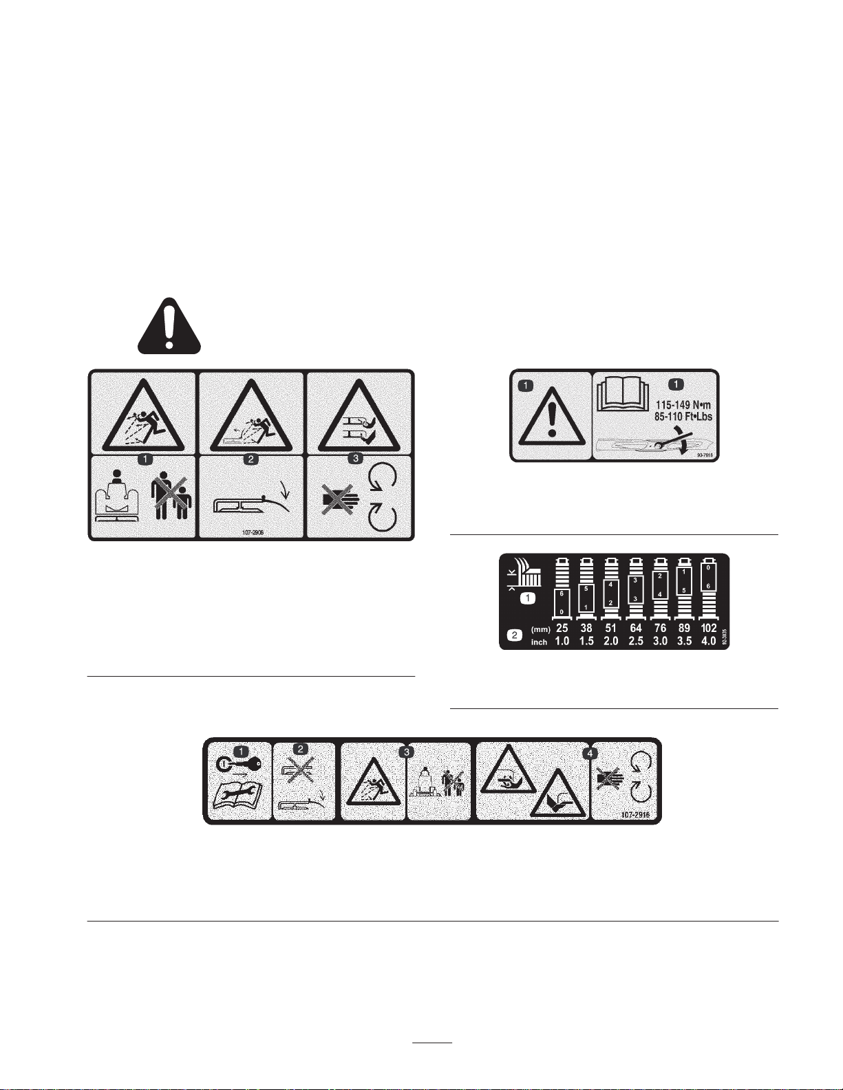
Safety and Instruction Decals
Safety decals and instructions are easily visible to the operator and are located near any area
of potential danger. Replace any decal that is damaged or lost.
• To make sure of optimum performance and continued
safety certification of the machine, use only genuine
Toro replacement parts and accessories. Replacement
parts and accessories made by other manufacturers
could be dangerous, and such use could void the
product warranty.
107-2908
1. Thrown object
hazard—keep bystanders
a safe distance from the
machine.
2. Thrown object hazard,
mower—keep the
deflector in place.
1. Remove the ignition key and
read the instructions before
servicing or performing
maintenance.
3. Cutting/dismemberment
hazard of hand or foot,
mower blade—stay away
from moving parts.
2. Do not operate the mower
with the deflector up or
removed; keep the deflector
in place.
1. Warning—read the
torquing the blade bolt/nut to 115–149 N⋅m (85–110 ft.-lb.).
1. Height of cut 2. Height settings
107-2916
3. Thrown object hazard—keep
bystanders a safe distance
from the machine.
93-7818
Operator’s Manual
92-3035
4. Cutting/dismemberment
hazard of hand or foot,
mower blade—stay away
from moving parts
for instructions on
5
Page 6
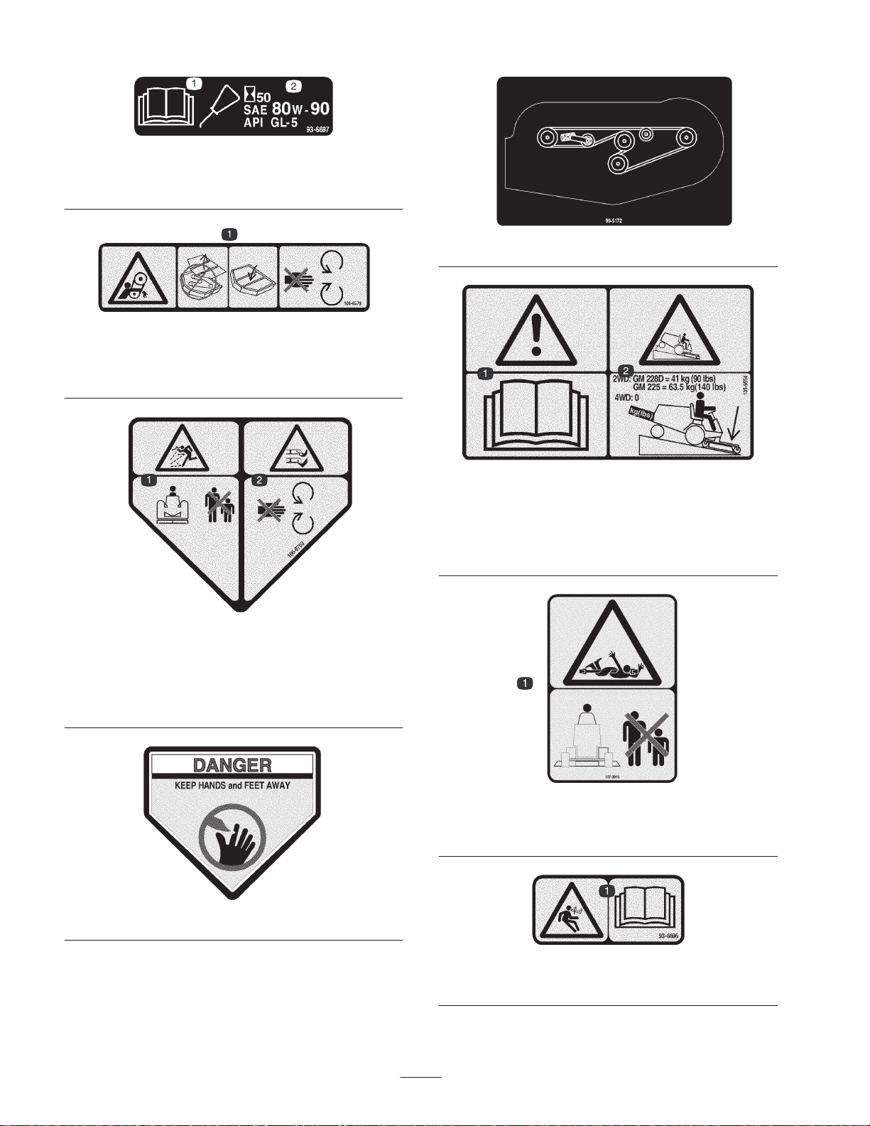
93-6697
1. Read the
Manual.
Operator’s
2. Add SAE 80w–90 (API
GL-5) oil every 50 hours.
100-6578
1. Entanglement hazard, belt—do not operate the machine with
the shields or guards removed; always keep the shields and
guards in place. Stay away from moving parts.
99-5172
105-9554
1. Warning—read the
2. Tipping hazard—lower the cutting unit when driving down
slopes. For 2 wheel drive units, add a 41 kg (90 lb) rear weight
to GM 228D units and a 63.5 kg (140 lb) rear weight to GM
225 units. For 4 wheel drive units, do not add weight.
Operator’s Manual.
Cover 43–8480 for CE
1. Thrown object
hazard—keep bystanders
a safe distance from the
machine.
106-6753
2. Cutting/dismemberment
43-8480
hazard of hand or foot,
mower blade—stay away
from moving parts.
107-2915
1. Entanglement hazard, shaft—keep bystanders a safe distance
from the machine.
93-6696
1. Stored energy hazard—read the
Operator’s Manual.
6
Page 7

Specifications
General Specifications
Width of Cut 71-5/8 in. (1.82 m)
Height of Cut Adjustable from 1 to 4 in. (25 to 102 mm) in 1/2 inch increments
Blade Tip Speed 16,270 ft./min. @ 3250 engine RPM
Cutting Blades 3 heat-treated steel blades, each 3/16 in. (4.8 mm) thick and 24-3/4 in. (55 cm) long
Unit Drive System
Castor Wheels
Note: Specifications and design subject to change without notice.
PTO driven gear box transmits power through a “AA” section belts to all blade
spindles.
Front: 8 in. (203 mm) diameter pneumatic wheels with greaseable roller bearings
(inflated to 35–50 psi [241–345 kPa])
Rear: 6 in. (152 mm) diameter hard rubber wheels with greaseable roller bearings
Optional Equipment
Leaf Mulcher Model No. 30779
Leaf Mulcher Discharge Plate Part No. 57-0700
Baffle Kit Part No. 99–5155
Atomic Blade Part No. 104–1304
Front Castor Wheel (Foam Filled) Part No. 93–5974
7
Page 8

Setup
Loose Parts
Note: Use this chart as a checklist to ensure that all parts have been received. Without these parts, total setup cannot be
completed.
Description Qty. Use
Front castor wheel assembly
Rear castor wheel assembly
Right-hand lift arm
Left-hand lift arm
Pivot pin assembly
Cotter pin, 5/32 in. x 1-3/4 in.
Capscrew, 7/16 x 3 in.
Flange nut, 7/16 in.
Mounting bracket
Lock pin assembly
Self-tapping screw
Spring cover assembly
Clevis pin
Hairpin cotter
Spring end—top
Heavy extension spring
Lower spring end
Knee link
Capscrew, 3/8 x 2-1/4 in.
Capscrew, 3/8 x 1 in.
Shoulder bolt
Flat washer
Locknut, 3/8 in.
2
2
1
1
2
2
4
4
2
4
4
2
2
2
2
2
2
2
4
4
4
4
12
Installing the castor wheel assemblies
Mount to traction unit pivot brackets
Connecting the lift arms to the cutting unit
Mounting the weight transfer kit
Decal 1 Apply for CE
Parts Catalog 1
Operator’s Manual 1 Read before operating the machine.
Note: Determine the left and right sides of the machine from the normal operating position.
8
Page 9
Danger
If the engine is started and the PTO shaft is
allowed to rotate, serious injury could result.
Do not start the engine and engage the PTO lever
when the PTO shaft is not connected to the gear
box on the cutting unit.
Install another thrust washer and the remaining spacers
onto the spindle and install the tensioning cap to secure
the assembly.
Important The thrust washers, not the spacers, must
contact the top and bottom of the castor arm.
3. Ensure that all four castor wheels are set at the same
height-of-cut and roll the cutting unit off of the pallet.
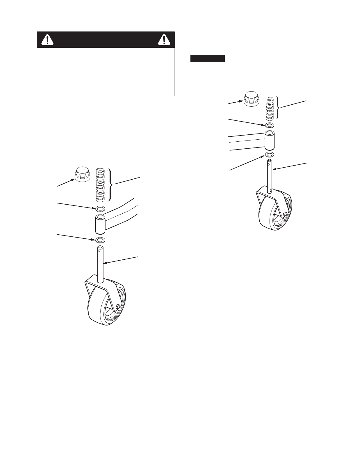
Installing the Castor Wheel
Assemblies
The thrust washers, spacers, and tensioning caps have been
installed on the castor wheel spindles for shipping.
1. Remove the tensioning caps from the spindle shafts and
slide off the spacers and thrust washers (Fig. 1 and 2).
3
1
2
2
4
1
2
2
1. Tensioning cap
2. Thrust washers
3
4
Figure 2
3. Spacers
4. Rear castor spindle
Figure 1
1. Tensioning cap
2. Thrust washers
2. Slide the spacers onto the castor spindle to get the
desired height-of-cut; refer to the Height-of-Cut Chart
on page 13. Slide a thrust washer onto the spindle, push
the round castor spindle through the front castor arm,
and the hex castor spindle through the rear castor arm.
3. Spacers
4. Front castor spindle
Installing the Lift Arms to the
Traction Unit
1. On one side of the traction unit, loosen (do not remove)
the wheel nuts securing the wheel and tire assembly to
the front wheel studs.
2. Jack up the machine until the front wheel is off of the
floor. Use jack stands or block the machine to prevent it
from accidentally falling.
3. Remove the wheel nuts and slide the wheel and tire
assembly off of the studs.
4. Mount a lift arm to the pivot bracket with a pivot pin
and cotter pin (5/32 x 1-3/4 in.) (Fig. 3). Mount the lift
arm with the ball joint end positioned outward.
5. Mount the rear of the lift arm to the lift cylinder with a
pivot pin and 2 cotter pins (supplied with the traction
unit).
9
Page 10

2
1
3
2-1/4 in.
(57 mm)
1
3
4
Figure 3
1. Pivot pin
2. Lift arm
3. Lift arm pivot bracket
4. Brake return spring
6. Hook the brake return spring to the hole in the lift arm
(Fig. 3).
7. Install the wheel and tire assembly. Torque the wheel
nuts to 45–55 ft.-lb. (62–72 N⋅m).
8. Repeat the procedure on the opposite side of the
machine.
Connecting the Lift Arms to the
Cutting Unit
1. Move the cutting unit into position in front of the
traction unit.
2. Measure the distance from the end of each lift arm to
the center of the ball joint (grease fitting). The distance
should be 2-1/4 in. (57 mm) (Fig. 4). If distance is not
2-1/4 in. (57 mm), loosen the jam nut securing the ball
joint to the lift arm and rotate the ball joint in or out
until the distance is attained. Do not tighten the jam nuts
at this time.
2
Figure 4
1. Lift arm
2. Ball joint
3. Jam nut
3. Move the lift lever to the Float position. Push the lift
arms down until the holes in the ball joint mounts line
up with the holes in the castor arms.
4. Secure the ball joint mounts to each castor arm with 2
capscrews (7/16 x 3 in.) and flange nuts (7/16 in.)
(Fig. 5).
Note: The ball joint mount should be above the castor arm
when it is assembled.
3
5
2
4
1
Figure 5
1. Castor arm
2. Ball joint mount
3. Ball joint
4. Capscrew
5. Flange nut
5. Tighten the large jam nut securing the ball joint to the
lift arm (Fig. 5). When tightening the jam nut, hold the
ball joint straight to permit proper oscillation during
raising and lowering of the cutting unit.
10
Page 11

Connecting the PTO Shaft to
the Cutting Unit Gear Box
1. Remove (2) capscrews and lockwashers securing PTO
guard mounting brackets to gearbox (Fig. 6). Retain
fasteners for re–installation.
2
1
3
Figure 6
1. Gearbox
2. PTO guard
2. Slide PTO shaft guard onto PTO shaft, positioning
guard as shown in figure 6.
3. Slide male PTO shaft into female PTO shaft. Align
mounting holes in gear case input shaft with holes in
PTO shaft and slide together.
4. Secure with roll pin.
5. Tighten capscrews and nuts.
3. PTO shaft
123 34
Figure 7
1. 52″ side discharge deck
2. 52″ deck w/bagger
3. To install the mounting brackets, insert 2 flange head
capscrews (3/8 x 1 in.) through the slotted bracket
holes. Thread the screws into the captivated frame nuts
and torque them to 45–50 ft.-lb. (61–68 N⋅m) (Fig. 8).
2
1
3. 62″ and 72″ decks
4. 52″ rear discharge deck
3
6. Re–install PTO shaft guard to gearbox with (2)
capscrews and lockwashers previously removed.
Installing the Weight Transfer
Kit
1. Fully raise the cutting deck, set the parking brake, stop
the engine, and remove the ignition key.
2. Place blocks under the cutting deck to prevent it from
falling during assembly.
Note: The mounting brackets for the weight transfer kit
must be installed in different locations depending on the
cutting deck. Refer to Figure 7 for mounting location.
Figure 8
1. Flange head capscrew
2. Slotted hole
4. Thread the top extension spring coil into the top spring
end holes and the bottom extension spring coil into the
bottom spring end holes (Fig. 9).
5. Mount the knee link to the lower spring end with the
wide part of the knee link pointing forward and the
spring end stop pointing forward. Secure the knee link
to the outer side of the spring end (Fig. 11) with a
shoulder bolt, washer, and locknut (Fig. 9 and 10).
Important The knee link must be assembled pointing
in the proper direction or the spring will not pivot correctly
when the deck is raised.
6. Mount the bottom of the knee link to the deck bracket
with a shoulder bolt and locknut.
3. Frame
11
Page 12

7. Align the slotted holes in the spring cover (slot toward
the bottom) with the mounting bracket holes. Insert the
lock pin assemblies into the bracket holes and secure
each to the bracket with the self-tapping screws (Fig. 9).
Torque the screws to 20 ft.-lb. (27 N⋅m).
4
3
2
1
2
8
11
12
10
1. Mounting bracket
2. Spring cover
3. Lock pin assembly
4. Self-tapping screw
5. Extension spring
6. Top spring end
7. Bottom spring end
Figure 9
9
6
5
7
13
8. Clevis pin
9. Hairpin cotter
10. Knee link
11. Shoulder bolt
12. Spring end stop
13. Locknut (2)
1
3
4
5
6
Figure 11
1. Weight transfer spring
2. Spring end plate
3. Knee link bracket
4. Deck bracket
5. Deck frame
6. Flotation frame
8. From the bottom, insert the spring and top spring end
into the spring cover. Select a hole that matches the
cutter deck height-of-cut setting; i.e., the top cover hole
matches the highest height setting, the bottom cover
hole the lowest, etc. Align the top spring end hole with
the selected spring cover holes and insert the clevis pin
to secure the spring inside the cover (Fig. 9). Secure the
clevis pin with a hairpin cotter.
1. Wide part of knee link
Figure 10
9. Remove the blocks from under the cutting unit. Make
the final counterbalance adjustments under actual
cutting conditions; refer to Adjusting the Tension
Spring, page 16.
1
Installing Rear Weight
Two Wheel Drive Groundsmaster 1000 and 200 Series
traction units comply with the ANSI B71.4-1999 Standard
when equipped with rear weight. Refer to the chart in the
traction unit Operator’s Manual to determine the
combinations of weight required. Order the parts from your
local Authorized Toro Distributor.
Four Wheel Drive Groundsmaster 200 Series traction units
do not need additional rear weight to comply with the
ANSI B71.4-1999 Standard.
12
Page 13

Before Operating
2
Adjusting the Height-of-Cut
The height-of-cut is adjustable from 1 to 4 inches (25 to
102 mm) in 1/2 inch (13 mm) increments, by adding or
removing an equal number of spacers on the front and rear
castor forks. The height-of-cut chart below gives the
combinations of spacers to use for all height-of-cut settings.
Height-of-Cut
Setting
(inches)
1 (25 mm) 0 0
1-1/2 (38 mm) 1 1
2 (51 mm) 2 2
2-1/2 (64 mm) 3 3
3 (76 mm) 4 4
3-1/2 (89 mm) 5 5
4 (102 mm) 6 6
Start the engine and raise the cutting unit so that the
height-of-cut can be changed. Stop the engine after the
cutting unit is raised.
Spacers Below Castor Arm
Front Rear
3
4
1
Figure 12
1. Front castor wheel
2. Tensioning cap
2. Push the castor spindle through the front castor arm,
install the other thrust washer and remaining spacers
onto the spindle, and install the tensioning cap to secure
the assembly.
3. Spacers
4. Thrust washers
Rear Castor Wheels
Front Castor Wheels
1. Remove the tensioning cap from the spindle shaft and
slide the spindle out of the front castor arm (Fig. 12).
Remove the washer from the spindle shaft. Slide the
spacers onto the spindle shaft to get the desired
height-of-cut, then slide the washer onto the shaft.
1. Remove the tensioning cap from the spindle shaft
(Fig. 13).
2
3
4
1
Figure 13
1. Rear castor wheel
2. Tensioning cap
3. Spacers
4. Thrust washers
Note: The rear castor fork assembly does not need to be
removed from the castor arm to change the height-of-cut.
13
Page 14

2. Remove or add ”C” shaped spacers at the narrow
portion of the spindle shaft, below the castor arm, to get
the desired height-of-cut. Make sure that the thrust
washers, not the spacers, contact the top and bottom of
the castor arm.
3. Install the tensioning cap to secure the assembly.
4. Ensure that all four castor wheels are set at the same
height-of-cut.
Adjusting the Rollers and Gage
Wheel
Note: If the cutting unit is to be used in the 1 in. (25 mm)
or 1-1/2 in. (38 mm) height-of-cut setting, the cutting unit
rollers must be repositioned in the top bracket holes.
Adjusting the Front Gage Wheel
1. Remove the capscrew and nut securing the gage wheel
to the cutting unit brackets (Fig. 15).
2. Align the roller and spacer with the top holes in the
brackets and secure them with the capscrew and nut.
Adjusting the Front Roller
1. Remove the capscrew and nut securing the roller shaft
to the cutting unit bracket (Fig. 14).
2. Slide the shaft out of the lower bracket holes, align the
roller with the top holes, and install the shaft.
3. Secure the roller shaft to the cutting unit bracket with
the capscrew and nut.
1
Figure 14
1. External roller 2. Roller shaft
2
1
Figure 15
1. Gage wheel
Adjusting the Rear (Internal) Rollers
1. Remove the cotter pins securing the roller shafts to the
brackets on the underside of the deck (Fig. 16).
2. Slide the shafts out of the lower bracket holes, align the
rollers with the top holes, and install the shafts.
3. Install the cotter pins to secure the assemblies.
1. Internal rollers
14
1
Figure 16
Page 15

Checking the Lubricant in the
Gear Box
The gear box in designed to operate on SAE 80–90 wt. gear
lube. Although the gear box is shipped with lubricant from
the factory, check the level before operating the cutting
unit.
1. Position the machine and cutting unit on a level surface.
2. Position the machine and cutting unit on a level surface
and lower the cutting unit. Remove the dipstick/fill plug
from the top of the gear box (Fig. 23) and make sure
that the lubricant is between the marks on the dipstick.
If the lubricant level is low, add SAE 80–90 wt. gear
lube until the level is between the marks.
Operation
Note: Determine the left and right sides of the machine
from the normal operating position.
Using the Grass Deflector
Danger
Without the grass deflector mounted in place, you
and others are exposed to blade contact and
thrown debris. Contact with the rotating mower
blade(s) and thrown debris will cause injury or
death.
1
Figure 17
1. Fill/check plug
Greasing the Cutting Unit
Before the cutting unit is operated, it must be greased to
ensure proper lubricating characteristics; refer to Greasing
the Bearings, Bushings, and Gear Box, page 17. Failure to
properly grease the cutting unit will result in premature
failure of critical parts.
• Never remove the grass deflector from the
mower because the grass deflector routes
material down toward the turf. If the grass
deflector is ever damaged, replace it
immediately.
• Never put your hands or feet under the mower.
• Never operate the mower with the deflector
removed from the cutting unit or tied/blocked in
a raised position.
Note: The deflector is spring loaded into its downward
normal operating position (Fig. 18), but the operator can
temporarily swing it out of the way to facilitate loading in a
trailer or when otherwise necessary.
2
Figure 18
1. Grass deflector 2. Springs
15
1
Page 16

Adjusting the Tension Spring
For best performance, the cutting unit bounce on uneven
turf is minimal and it does not ride heavily over flat terrain.
If scalping occurs or the cut is uneven from side to side,
there may too much weight on the deck and weight may
have to be transferred to the traction unit: i.e. increased
spring tension.
By contrast, if too much weight is transferred to the traction
unit, the deck will bounce excessively and the cut will be
uneven. If the cutting unit does not perform properly, adjust
the tension spring as follows:
1. Stop the machine on a level surface, set the parking
brake, fully raise the cutting unit, turn the ignition key
to Off, and remove the key.
2. Remove the hairpin cotter from the clevis pin securing
the spring end to the spring cover and remove the clevis
pin. Align the top spring end hole with the new hole
selected in the spring cover, insert the clevis pin, and
secure it with the hairpin cotter.
3. Resume operations. If further adjustments are required,
repeat the procedure.
Caution
The counterbalance spring is in tension when the
deck is in the lowered position.
Always raise the deck before adjusting or
removing the spring.
16
Page 17

Maintenance
Note: Determine the left and right sides of the machine
from the normal operating position.
Recommended Maintenance Schedule
Maintenance Service
Interval
After first 2 hours • Tighten the castor wheel nuts.
After first 10 hours
Daily
Every 50 hours
Every 400 hours • Change the gear box oil.
Maintenance Procedure
• Tighten the castor wheel nuts.
• Torque the blade bolts.
• Check the blades.
• Lubricate the castor arm bushings.
• Lubricate the castor wheel bearings.
• Tighten the castor wheel nuts.
• Torque the blade bolts.
• Lubricate the grease fittings.
• Clean under the cutting unit belt covers.
• Check the blade drive belt adjustment.
• Check the gear box oil level.
Greasing the Bearings,
Bushings, and Gear Box
The cutting unit must be lubricated regularly. If the
machine is operated under normal conditions, lubricate the
castor bearings and bushings with No. 2 general purpose
lithium base grease or molybdenum base grease after every
8 hours of operation or daily, whichever comes first.
1. Lubricate the following areas:
• front castor spindle bushings (Fig. 19)
• rear castor spindle shaft (remove the shaft from the
castor arm and coat the hexagonal shaft with
designated grease every 50 hours) (Fig. 20)
• castor wheel bearings (Fig. 19 and 20)
• right and left lift arm pivot pins (Fig. 21)
• blade spindle bearings (Fig. 22)
• right and left push arm ball joints (Fig. 22)
Figure 19
17
Page 18

Figure 20
2. Position the machine and cutting unit on a level surface
and lower the cutting unit. Remove the dipstick/fill plug
from the top of the gear box (Fig. 23) and make sure
that the lubricant is between the marks on the dipstick.
If the lubricant level is low, add SAE 80–90 wt. gear
lube until the level is between the marks.
1
Figure 23
1. Fill/check plug
Figure 21
Figure 22
Separating the Cutting Unit
from the Traction Unit
1. Position the machine on a level surface, raise the cutting
unit, engage the parking brake, put the traction pedal in
neutral, the PTO lever in the Off position, shut the
engine off, and remove the ignition key.
Caution
The counterbalance spring is in tension when the
deck is in the lowered position.
Always raise the deck before adjusting or
removing the spring.
2. Disconnect the counterbalance from the traction unit,
remove the lock pins from the brackets, separate the
spring tension assemblies from the brackets, and lay
them down on the deck. Loosely secure the lock pins to
the brackets to prevent losing them (Fig. 24).
18
Page 19

1. Lock pin
2. Bracket
23
1
Figure 26
1. PTO shaft
Figure 24
3. Spring tension assembly
Danger
1
3. Position the machine on a level surface, lower the
cutting unit to the floor, move the lift lever to the float
position, shut the engine off, and engage the parking
brake.
4. Remove the capscrews and locknuts securing the ball
joint mounts to the castor arms on the cutting unit
(Fig. 25).
2
1
Figure 25
1. Castor arm 2. Ball joint mount
If the engine is started and the PTO shaft is
allowed to rotate, serious injury could result.
Do not start the engine and engage the PTO lever
when the PTO shaft is not connected to the gear
box on the cutting unit.
Mounting the Cutting Unit to
the Traction Unit
1. Position the machine on a level surface and shut the
engine off.
2. Move the cutting unit into position in front of the
traction unit.
3. Slide the male PTO shaft into the female PTO shaft.
(Fig. 26)
4. Move the lift lever to the Float position. Push the lift
arms down until the holes in the ball joint mounts line
up with the holes in the castor arms (Fig. 25).
5. Secure the ball joint mounts to the castor arms with the
capscrews and flange nuts.
5. Roll the cutting unit away from the traction unit,
separating the male and female sections of the PTO
shaft (Fig. 26).
6. Raise the cutting unit and place blocks under it to
prevent it from falling during assembly.
7. Connect the counterbalance to the traction unit brackets
with lock pins (Fig. 24).
8. Remove the blocks from under the cutting unit. Make
the final counterbalance adjustments under actual
cutting conditions; refer to Adjusting the Tension
Spring, page 16.
19
Page 20
Servicing the Castor Arm
Bushings
lubricated, bearing wear will be minimal. However, failure
to keep the bearing lubricated will cause rapid wear. A
wobbly castor wheel usually indicates a worn bearing.
The castor arms have bushings pressed into the top and
bottom of the tube and after many hours of operation, the
bushings will wear. To check the bushings, move the castor
fork back and forth and from side to side. If the castor
spindle is loose inside the bushings, the bushings are worn
and must be replaced.
1. Raise the cutting unit so that the wheels are off of the
floor and block it so that it cannot accidentally fall.
2. Remove the tensioning cap, spacer(s), and thrust washer
from the top of the castor spindle.
3. Pull the castor spindle out of the mounting tube. Allow
the thrust washer and spacer(s) to remain on the bottom
of the spindle.
4. Insert a pin punch into the top or bottom of the
mounting tube and drive the bushing out of the tube.
Also drive the other bushing out of the tube (Fig. 27).
Clean the inside of the tubes to remove dirt.
2
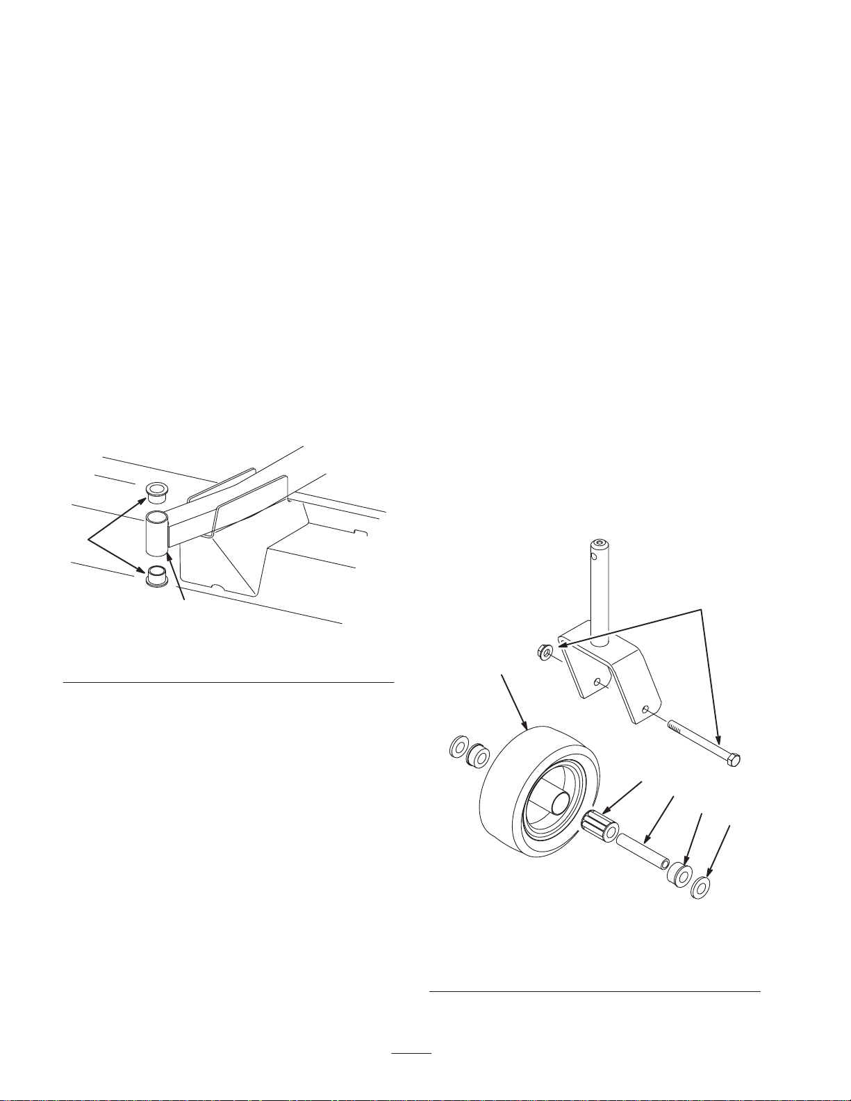
1. Remove the locknut from the capscrew holding the
castor wheel assembly between the castor fork
(Fig. 28). Grasp the castor wheel and slide the capscrew
out of the fork.
2. Pull the spanner bushing out of the wheel hub (Fig. 28).
3. Remove the bushing from the wheel hub and allow the
bearing to fall out. Remove the bushing from the
opposite side of the wheel hub.
4. Check the bearing, spanner, and inside of the wheel hub
for wear. Replace damaged parts.
5. To assemble the castor wheel, push the bushing into the
wheel hub. Slide the bearing into the wheel hub. Push
the other bushing into the open end of the wheel hub to
captivate the bearing inside the wheel hub (Fig. 28).
6. Carefully slide the spanner through the bushings and the
wheel hub.
7. Install the castor wheel assembly between the castor
fork and secure it in place with the capscrew, washers,
and locknut.
8. Lubricate the castor wheel bearing through the grease
fitting, using No. 2 general purpose lithium base grease.
1
Figure 27
1. Front castor arm tube 2. Bushings
5. Apply grease to the inside and outside of the new
bushings. Using a hammer and flat plate, drive the
bushings into the mounting tube.
6. Inspect the castor spindle for wear and replace it if it is
damaged.
7. Push the castor spindle through the bushings and
mounting tube. Slide the thrust washer and spacer(s)
onto the spindle. Install the tensioning cap on the castor
spindle to retain all of the parts in place.
Servicing the Castor Wheels
and Bearings
The castor wheel rotates on a high-quality roller bearing
and is supported by a spanner bushing. Even after many
hours of use, provided that the bearing was kept well
1
1. Castor wheel
2. Capscrew and locknut
3. Bushing (2)
2
5
4
3
6
Figure 28
4. Spanner bushing
5. Roller bearing
6. Washer (2)
20
Page 21

Checking for a Bent Blade
1. Position the machine on a level surface, raise the cutting
unit, engage the parking brake, put the traction pedal in
neutral, the PTO lever in the Off position, shut the
engine Off, remove the ignition key, and disconnect the
wires from the spark plugs. Block the cutting unit to
prevent it from accidentally falling.
2. Grasp the end of the blade using a rag or thickly padded
glove. Remove the blade bolt, anti-scalp cup, and blade
from the spindle shaft (Fig. 30).
2. Rotate the blade until the ends face forward and
backward. Measure from the inside of the cutting unit to
the cutting edge at the front of the blade (Fig. 29), and
remember this dimension.
Figure 29
3. Rotate the opposite end of the blade forward. Measure
between the cutting unit and cutting edge of the blade at
the same position as in step 2. The difference between
the dimensions obtained in steps 2 and 3 must not
exceed 1/8 in. (3 mm). If the dimension exceeds 1/8 in.
(3 mm), replace the blade because it is bent; refer to
Removing the Cutting Blade, page 21.
Removing the Cutting Blade
The blade must be replaced if a solid object is hit, or the
blade is out-of-balance, worn, or bent. Always use genuine
Toro replacement blades to ensure safety and optimum
performance. Never use blades made by other
manufacturers because they could be dangerous.
Danger
A worn or damaged blade can break, and a piece
of the blade could be thrown into the operator’s or
bystander’s area, resulting in serious personal
injury or death.
• Inspect the blade periodically for wear or
damage.
• Do not try to straighten a blade that is bent.
• Never weld a broken or cracked blade.
• Replace a worn or damaged blade with a new
Toro blade to ensure continued safety
certification of the product.
1. Position the machine on a level surface, raise the cutting
unit, engage the parking brake, put the traction pedal in
neutral, the PTO lever in the Off position, shut the
engine off, remove the ignition key, and disconnect the
wires from the spark plugs. Block the cutting unit to
prevent it from accidentally falling.
2
1
Figure 30
1. Blade bolt 2. Anti-scalp cup
3. Install the blade—sail facing toward the cutting
unit—with the anti-scalp cup and blade bolt. Tighten
the blade bolt to 85–110 ft.-lb. (115–149 N⋅m).
Inspecting and Sharpening the
Blade
Two areas must be considered when checking and servicing
the cutting blade: the sail and the cutting edge. Both cutting
edges and the sail, which is the turned up portion opposite
the cutting edge, contribute to a good quality-of-cut. The
sail is important because it pulls grass up straight, thereby
producing an even cut. However, the sail will gradually
wear down during operation, and this condition is normal.
As the sail wears down, the quality-of-cut will degrade
somewhat, although the cutting edges are sharp. The
cutting edge of the blade must be sharp so that the grass is
cut rather than torn. A dull cutting edge is evident when the
tips of the grass appear brown and shredded. Sharpen the
cutting edges to correct this condition.
1. Position the machine on a level surface, raise the cutting
unit, engage the parking brake, put the traction pedal in
neutral, the PTO lever in the Off position, shut the
engine off, remove the ignition key, and disconnect the
wires from the spark plugs. Block the cutting unit to
prevent it from accidentally falling.
2. Examine the cutting ends of the blade carefully,
especially where the flat and curved parts of the blade
meet (Fig. 31-A). Since sand and abrasive material can
wear away the metal that connects the flat and curved
parts of the blade, check the blade before using the
machine. If wear is noticed (Fig. 31-B), replace the
blade; refer to Removing the Cutting Blade, page 21.
21
Page 22

FLAT PART
OF BLADE
with the anti-scalp cup and blade bolt. The blade sails must
be on top of the blade. Tighten the blade bolt to
85–110 ft.-lb. (115–149 N⋅m).
A
SAIL
Correcting Cutting Unit
SAIL
B
WEAR
SAIL
C
SLOT
FORMED
Figure 31
3. Examine the cutting edges of all blades. Sharpen the
cutting edges if they are dull or nicked. Sharpen only
the top side of the cutting edge and maintain the
original cutting angle to ensure sharpness (Fig. 32). The
blade will remain balanced if the same amount of metal
is removed from both cutting edges.
Warning
If the blade is allowed to wear, a slot will form
between the sail and flat part of the blade
(Fig. 31-C). Eventually, a piece of the blade may
break off and be thrown from under the housing,
possibly resulting in serious injury to yourself or
bystanders.
Mismatch
If one cutting blade cuts lower than the others, correct them
as follows:
1. Lower the cutting unit onto a level surface, engage the
parking brake, put the traction pedal in neutral, the PTO
lever in the Off position, shut the engine off, remove the
ignition key, and disconnect the wires from the spark
plugs. Make sure that the tire pressure is equal on all
tires.
2. Raise the height-of-cut to the 4 in. (102 mm) position;
refer to Adjusting the Height-of-Cut, page 13.
3. Rotate the blades so that the tips line up with one
another. The tips of the adjacent blades must be within
1/8 in. (3 mm) of each other. If the tips are not within
1/8 in. (3 mm) of each other, proceed to step 9 and add
shims between the spindle housing and bottom of the
cutting unit.
4. Check to make sure that the front height-of-cut pins are
resting properly on the frame cushions. If the pins are
not resting properly, place a shim or shims under the
cushion to raise it for proper alignment.
5. Position all 3 blades in the “A” position (Fig. 33) and
measure from the level surface to the bottom of the tip
end of each blade (Fig. 34).
B
• Inspect the blade periodically for wear or
damage.
• Replace a worn or damaged blade with a new
Toro blade to ensure continued safety
certification of the product.
SHARPEN AT THIS
ANGLE ONLY
END VIEW
OF BLADE
Figure 32
Note: Remove the blades and sharpen them on a grinder;
refer to Removing the Cutting Blades, page 21, steps 1
and 2. After sharpening the cutting edges, install the blade
B
A
A
C
C
A
Figure 33
6. Note the measurement attained at “A”, rotate the blades
to the “B” position (Fig. 33), measure the distance of all
of the blades to the level surface, and note the
dimensions (Fig. 34).
22
B
C
Page 23

MEASURE FROM
BLADE TIP TO LEVEL
SURFACE
Figure 34
7. Rotate the blades to the “C” position, measure, and note
the distance measured (Fig. 33 and 34).
8. Compare the measurements at various positions. All
dimensions must be equal within 1/4 in. (6 mm) from
any 2 adjacent blades. The difference between the
dimensions of all 3 blades must not exceed 3/8 in.
(10 mm). If the difference exceeds specifications,
proceed to step 9.
9. Remove the capscrews, flat washers, and locknuts from
the outer spindle in the area where the shims must be
added. To raise or lower the blade, add a shim, Part No.
3256-24, between the spindle housing and bottom of the
cutting unit. Continue checking the alignment of the
blades and adding shims until the tips of the blades are
within the required dimension.
Replacing the Grass Deflector
1. Position the machine on a level surface, raise the cutting
unit, engage the parking brake, put the traction pedal in
neutral, the PTO lever in the Off position, shut the
engine off, and remove the ignition key. Block the
cutting unit to prevent it from accidentally falling.
2. Remove the 2 capscrews, locknuts, and springs securing
the deflector mounts to the pivot brackets (Fig. 35).
4. Install the pivot brackets on top of the discharge
opening with the carriage bolts and nuts. The head of
the carriage bolts must be on the inside of the cutting
unit.
5. Position the deflector mounts on the pivot brackets and
secure the parts together with the capscrews, locknuts,
and springs. Both locknuts must face each other.
Tighten the locknuts until they are flush against the
deflector pivots.
6. Lift the deflector and allow it to drop to check the
spring tension. The deflector must be held firmly in the
full downward position by the spring tension. Correct it
if necessary.
Adjusting the Idler Pulley
The idler pulley applies force against the belt so that power
can be transmitted to the blade pulleys. If the idler is not
tensioned against the belt with sufficient force, maximum
power will not be transmitted to the pulleys. Tension on the
belt requires 40 to 50 ft.-lb. (54 to 68 N⋅m) of torque on the
large nut, which applies force against the belt. If the idler is
not adjusted to these specifications, an adjustment is
necessary.
1. Position the machine on a level surface, lower the
cutting unit, engage the parking brake, put the traction
pedal in neutral, the PTO lever in the Off position, shut
the engine off, and remove the ignition key.
2. Release and unhook the latches securing the center
cover to the top of the cutting unit. Remove the cover
from the cutting unit.
3. Loosen the 2 nuts securing the idler plate in place.
Using a socket and torque wrench, tighten the idler
adjusting nut to 40–50 ft.-lb. (54 to 68 N⋅m) (Fig. 36).
1
2
3
Figure 35
1. Deflector mounts
2. Pivot brackets
3. Pivot springs
3. To remove the pivot brackets, remove the carriage bolts
and nuts (Fig. 35).
2
1
3
2
Figure 36
1. Idler plate
2. Nuts (2)
3. Idler adjusting nut
4. Hold the torque against the belt and tighten the 2 nuts so
that the idler plate is held securely in place. Release the
idler adjusting nut. Install the cover and secure the
latches.
23
Page 24

Adjusting the Cover Latches
If the cutting unit covers fit loose, the latch tension may be
adjusted by loosening the latch mounting screws and
sliding the latches (slotted mounting holes in the cutting
unit) to the proper position.
Replacing the Drive Belt
The blade drive belt, tensioned by the adjustable idler, is
very durable. However, after many hours of use, the belt
will show signs of wear. Signs of a worn belt are: squealing
when the belt is rotating, blades slipping when cutting
grass, frayed edges, burn marks, and cracks. Replace the
belt if any of these conditions are evident.
1. Position the machine on a level surface, lower the
cutting unit, engage the parking brake, put the traction
pedal in neutral, the PTO lever in the Off position, shut
the engine off, and remove the ignition key.
2. Release and unhook the latches securing the covers to
the top of the cutting unit. Remove the covers.
3. Loosen the 2 nuts securing the idler plate in place and
remove the old belt from the pulleys.
4. To install a new belt, the gear box base must be
removed. To do this, remove the 4 carriage bolts and
locknuts holding the gear box base.
5. Install the new belt around the gear box pulley, spindle
pulleys, stationary idler pulley, and adjustable idler
pulley (Fig. 37).
6. Install the gear box base with the carriage bolts and
locknuts.
7. Using a torque wrench, adjust the tension of the idler
pulley against the belt; refer to Adjusting the Idler
Pulley, page 23.
8. Install the covers and secure the latches.
2
3
1
Figure 37
1. Adjustable idler pulley
2. Stationary idler pulley
3. Gear box pulley
24
Page 25

UNIT WILL NOT CUT OR CUTS POORLY
Troubleshooting
25
INSPECT
CUTTER
BLADES
DULL OR
BENT
SHARPEN
OR
REPLACE
INSPECT PULLEY
ON ENGINE
OUTPUT SHAFT
LOOSE OR
BROKEN
REPLACE
OK OK
INSPECT
SPINDLE
BOLTS
LOOSE
RETORQUE
85 TO 110
FOOT POUNDS
INSPECT
P.T.O.
SHAFT
BROKEN
REPLACE
INSPECT
CUTTER DECK
BELTS
LOOSE OR
BROKEN
TIGHTEN
OR
REPLACE
INSPECT
P.T.O.
PULLEY
LOOSE OR
BROKEN
TIGHTEN
OR
REPLACE
INSPECT
GEAR BOX
PULLEY
LOOSE
TIGHTEN
OR
REPLACE
OKOK OK
OKOK
INSPECT
GEAR BOX
SHAFTS
BROKEN
REPLACE
INSPECT
P.T.O.
BELT
BROKEN
REPLACE
Page 26

26
Page 27

27
Page 28

The Toro General Commercial Products Warranty
A Two-Year Limited Warranty
Conditions and Products Covered
The Toro Company and its affiliate, Toro Warranty Company,
pursuant to an agreement between them, jointly warrant your Toro
Commercial Product (“Product”) to be free from defects in
materials or workmanship for two years or 1500 operational
hours*, whichever occurs first. Where a warrantable condition
exists, we will repair the Product at no cost to you including
diagnosis, labor, parts, and transportation. This warranty begins
on the date the Product is delivered to the original retail purchaser.
* Product equipped with hour meter
Instructions for Obtaining Warranty Service
You are responsible for notifying the Commercial Products
Distributor or Authorized Commercial Products Dealer from whom
you purchased the Product as soon as you believe a warrantable
condition exists.
If you need help locating a Commercial Products Distributor or
Authorized Dealer, or if you have questions regarding your
warranty rights or responsibilities, you may contact us at:
Toro Commercial Products Service Department
Toro Warranty Company
8111 Lyndale Avenue South
Bloomington, MN 55420-1196
952-888-8801 or 800-982-2740
E-mail: commercial.service@toro.com
Owner Responsibilities
As the Product owner, you are responsible for required maintenance and adjustments stated in your operator’s manual. Failure
to perform required maintenance and adjustments can be grounds
for disallowing a warranty claim.
Items and Conditions Not Covered
Not all product failures or malfunctions that occur during the
warranty period are defects in materials or workmanship. This
express warranty does not cover the following:
• Product failures which result from the use of non-Toro
replacement parts, or from installation and use of add-on,
modified, or unapproved accessories
• Product failures which result from failure to perform required
maintenance and/or adjustments
• Product failures which result from operating the Product in an
abusive, negligent or reckless manner
• Parts subject to consumption through use unless found to be
defective. Examples of parts which are consumed, or used up,
during normal Product operation include, but are not limited to,
blades, reels, bedknives, tines, spark plugs, castor wheels,
tires, filters, belts, etc.
• Failures caused by outside influence. Items considered to be
outside influence include, but are not limited to, weather,
storage practices, contamination, use of unapproved coolants,
lubricants, additives, or chemicals, etc.
• Normal “wear and tear” items. Normal “wear and tear”
includes, but is not limited to, damage to seats due to wear or
abrasion, worn painted surfaces, scratched decals or windows, etc.
Parts
Parts scheduled for replacement as required maintenance are
warranted for the period of time up to the scheduled replacement
time for that part.
Parts replaced under this warranty become the property of Toro.
Toro will make the final decision whether to repair any existing part
or assembly or replace it. Toro may use factory remanufactured
parts rather than new parts for some warranty repairs.
General Conditions
Repair by an Authorized Toro Distributor or Dealer is your sole
remedy under this warranty.
Neither The Toro Company nor Toro Warranty Company is
liable for indirect, incidental or consequential damages in
connection with the use of the Toro Products covered by this
warranty, including any cost or expense of providing substitute equipment or service during reasonable periods of
malfunction or non-use pending completion of repairs under
this warranty . Except for the Emissions warranty referenced
below, if applicable, there is no other express warranty. All
implied warranties of merchantability and fitness for use are
limited to the duration of this express warranty.
Some states d o n o t a l l o w exclusions of incidental or consequential
damages, or limitations on how long an implied warranty lasts, so
the above exclusions and limitations may not apply to you.
This warranty gives you specific legal rights, and you may also
have other rights which vary from state to state.
Note regarding engine warranty: The Emissions Control
System on your Product may be covered by a separate warranty
meeting requirements established by the U.S. Environmental
Protection Agency (EPA) and/or the California Air Resources
Board (CARB). The hour limitations set forth above do not apply to
the Emissions Control System Warranty. Refer to the Engine
Emission Control Warranty Statement printed in your operator’s
manual or contained in the engine manufacturer’s documentation
for details.
Countries Other than the United States or Canada
Customers who have purchased Toro products exported from the United States or Canada should contact their T oro Distributor (Dealer)
to obtain guarantee policies for your country , province, or state. If for any reason you are dissatisfied with your Distributor’s service or
have difficulty obtaining guarantee information, contact the Toro importer. If all other remedies fail, you may contact us at Toro Warranty
Company.
Part No. 374-0031 Rev. a
 Loading...