

Toro 30551, Groundsmaster 200 Series, Groundsmaster 3320 Series, Groundsmaster 3280-D Series Operator's Manual
Page 1
62inSideDischargeMower
FormNo.3383-259RevA
Groundsmaster
®
200,3320and3280-D
SeriesTractionUnit
ModelNo.30551—SerialNo.314000001andUp
Registeratwww.T oro.com.
OriginalInstructions(EN)
*3383-259*A
Page 2

Figure1
Introduction
ThisproductcomplieswithallrelevantEuropeandirectives,
fordetailspleaseseetheseparateproductspecicDeclaration
ofConformity(DOC)sheet.
WARNING
CALIFORNIA
Proposition65Warning
Thisproductcontainsachemicalorchemicals
knowntotheStateofCaliforniatocausecancer,
birthdefects,orreproductiveharm.
Thisrotary-bladelawncuttingdeckismountedtoaride-on
machineandisintendedtobeusedbyprofessional,hired
operatorsincommercialapplications.Itisprimarilydesigned
forcuttinggrassonwell-maintainedlawnsinparks,sports
elds,andoncommercialgrounds.Itisnotdesignedfor
cuttingbrush,mowinggrassandothergrowthalongside
highways,orforagriculturaluses.
Readthisinformationcarefullytolearnhowtooperateand
maintainyourproductproperlyandtoavoidinjuryand
productdamage.Youareresponsibleforoperatingthe
productproperlyandsafely.
1.Safetyalertsymbol
Thismanualuses2otherwordstohighlightinformation.
Importantcallsattentiontospecialmechanicalinformation
andNoteemphasizesgeneralinformationworthyofspecial
attention.
YoumaycontactTorodirectlyatwww.Toro.comforproduct
andaccessoryinformation,helpndingadealer,ortoregister
yourproduct.
Wheneveryouneedservice,genuineT oroparts,oradditional
information,contactanAuthorizedServiceDealerorToro
CustomerServiceandhavethemodelandserialnumbers
ofyourproductready .Themodelandserialnumbersare
stampedintoaplatelocatedonthecarrierframebehindthe
rightfrontcastorwheel.Writethenumbersinthespace
provided.
ModelNo.
SerialNo.
Thismanualidentiespotentialhazardsandhassafety
messagesidentiedbythesafetyalertsymbol(Figure1),
whichsignalsahazardthatmaycauseseriousinjuryordeath
ifyoudonotfollowtherecommendedprecautions.
©2014—TheToro®Company
8111LyndaleAvenueSouth
Bloomington,MN55420
Contactusatwww.Toro.com.
2
PrintedintheUSA
AllRightsReserved
Page 3

Contents
Introduction..................................................................2
Safety...........................................................................4
SafeOperatingPractices...........................................4
ToroMowerSafety..................................................5
SafetyandInstructionalDecals.................................7
Setup............................................................................9
1InstallingtheCastorWheelAssemblies....................9
2InstallingtheLiftArms.........................................10
3ConnectingtheLiftArmstotheCutting
Unit..................................................................11
4MountingthePTOShaftGuardandConnecting
thePTOShafttotheCuttingUnitGear
Box...................................................................11
5InstallingtheRearW eight......................................12
ProductOverview.........................................................13
Specications........................................................13
Attachments/Accessories........................................13
Operation....................................................................13
AdjustingtheHeight-of-Cut....................................13
AdjustingtheRollersandGageWheel.......................14
............................................................................15
CheckingtheGearBoxLubricant.............................15
GreasingtheCuttingUnit........................................15
AdjustingtheWeightTransfer..................................15
UsingtheGrassDeector.......................................15
Maintenance.................................................................16
Lubrication............................................................16
SeparatingtheCuttingUnitfromtheTraction
Unit..................................................................16
MountingtheCuttingUnittotheTraction
Unit..................................................................17
ServicingtheBushingsintheCastorArms.................17
ServicingtheCastorWheelsandBearings..................18
CheckingforaBentBlade........................................18
RemovingtheCuttingBlade.....................................18
InspectingandSharpeningtheBlade.........................19
CheckingandCorrectingMismatchof
Blades...............................................................20
ReplacingtheGrassDeector..................................20
AdjustingtheIdlerPulley........................................21
ReplacingtheDriveBelt..........................................21
Troubleshooting...........................................................23
3
Page 4

Safety
ThismachinemeetsorexceedsCENstandardEN836:1997,
ISOstandard5395:1990,andANSIB71.4-2012specications
ineffectatthetimeofproduction.
Improperuseormaintenancebytheoperatororownercan
resultininjury.Toreducethepotentialforinjury,comply
withthesesafetyinstructionsandalwayspayattentiontothe
safetyalertsymbol,whichmeansCAUTION,WARNING,or
DANGER-"personalsafetyinstruction."Failuretocomply
withtheinstructionmayresultinpersonalinjuryordeath.
SafeOperatingPractices
ThefollowinginstructionsareadaptedfromtheCEN
standardEN836:1997,ISOstandard5395:1990,andANSI
B71.4-2012.
Training
•Readtheoperator'smanualandothertrainingmaterial
carefully.Befamiliarwiththecontrols,safetysigns,and
theproperuseoftheequipment.Iftheoperatoror
mechaniccannotreadthelanguageofthismanual,itis
theowner'sresponsibilitytoexplainthismaterialtothem.
•Becomefamiliarwiththesafeoperationoftheequipment,
operatorcontrols,andsafetysigns.
•Alloperatorsandmechanicsshouldbetrained.The
ownerisresponsiblefortrainingtheusers.
•Neverletchildrenoruntrainedpeopleoperateorservice
theequipment.Localregulationsmayrestricttheageof
theoperator.
•Theowner/usercanpreventandisresponsiblefor
accidentsorinjuriesoccurringtohimselforherself,other
people,orproperty.
Preparation
•Evaluatetheterraintodeterminewhataccessoriesand
attachmentsareneededtoproperlyandsafelyperform
thejob.Onlyuseaccessoriesandattachmentsapproved
bythemanufacturer.
•Wearappropriateclothingincludinghardhat,safety
glassesandearprotection.Longhair,looseclothingor
jewelrymaygettangledinmovingparts.
•Inspecttheareawheretheequipmentistobeusedand
removeallobjectssuchasrocks,toysandwirewhichcan
bethrownbythemachine.
•Checkthatoperator'spresencecontrols,safetyswitches
andshieldsareattachedandfunctioningproperly.Donot
operateunlesstheyarefunctioningproperly.
SafeHandlingofFuels
•Toavoidpersonalinjuryorpropertydamage,use
extremecareinhandlinggasoline.Gasolineisextremely
ammableandthevaporsareexplosive.
•Extinguishallcigarettes,cigars,pipes,andothersources
ofignition.
•Useonlyanapprovedfuelcontainer.
•Neverremovefuelcaporaddfuelwiththeengine
running.
•Allowenginetocoolbeforerefueling.
•Neverrefuelthemachineindoors.
•Neverstorethemachineorfuelcontainerwherethereis
anopename,spark,orpilotlightsuchasonawater
heateroronotherappliances.
•Neverllcontainersinsideavehicleoronatruckor
trailerbedwithaplasticliner.Alwaysplacecontainerson
thegroundawayfromyourvehiclebeforelling.
•Removeequipmentfromthetruckortrailerandrefuelit
ontheground.Ifthisisnotpossible,thenrefuelsuch
equipmentwithaportablecontainer,ratherthanfroma
fueldispensernozzle.
•Keepthenozzleincontactwiththerimofthefueltank
orcontaineropeningatalltimesuntilfuelingiscomplete.
Donotuseanozzlelockopendevice.
•Iffuelisspilledonclothing,changeclothingimmediately.
•Neveroverllfueltank.Replacefuelcapandtighten
securely.
Operation
•Neverrunanengineinanenclosedarea.
•Onlyoperateingoodlight,keepingawayfromholesand
hiddenhazards.
•Besurealldrivesareinneutralandparkingbrakeis
engagedbeforestartingengine.Onlystartenginefrom
theoperator'sposition.Useseatbeltsifprovided.
•Slowdownanduseextracareonhillsides.Besureto
travelintherecommendeddirectiononhillsides.Turf
conditionscanaffectthemachine'sstability .Usecaution
whileoperatingneardrop-offs.
•Slowdownandusecautionwhenmakingturnsandwhen
changingdirectionsonslopes.
•Neverraisedeckwiththebladesrunning.
•Neveroperatewithguardsnotsecurelyinplace.Be
sureallinterlocksareattached,adjustedproperly ,and
functioningproperty.
•Donotchangetheenginegovernorsettingoroverspeed
theengine.
•Stoponlevelground,lowerthecuttingunits,disengage
drives,engageparkingbrake(ifprovided),shutoffengine
beforeleavingtheoperator'spositionforanyreason.
•Stopequipmentandinspectthebladesafterstriking
objectsorifanabnormalvibrationoccurs.Make
necessaryrepairsbeforeresumingoperations.
•Keephandsandfeetawayfromthecuttingunits.
4
Page 5

•Lookbehindanddownbeforebackinguptobesureof
aclearpath.
•Nevercarrypassengersandkeeppetsandbystanders
away.
•Slowdownandusecautionwhenmakingturnsand
crossingroadsandsidewalks.Stopbladesifnotmowing.
•Donotoperatethemowerundertheinuenceofalcohol
ordrugs.
•Lightningcancausesevereinjuryordeath.Iflightning
isseenorthunderisheardinthearea,donotoperate
themachine;seekshelter.
•Usecarewhenloadingorunloadingthemachineintoa
trailerortruck.
•Usecarewhenapproachingblindcorners,shrubs,trees,
orotherobjectsthatmayobscurevision.
•Theoperatorshallturnonashingwarninglights,if
provided,whenevertravelingonapublicroad,except
wheresuchuseisprohibitedbylaw .
MaintenanceandStorage
•Disengagedrives,lowerthecuttingunits,movetraction
pedaltoNeutral,setparkingbrake,stopengineand
removekey .Waitforallmovementtostopbefore
adjusting,cleaningorrepairing.
•Cleangrassanddebrisfromcuttingunits,drives,mufers,
andenginetohelppreventres.Letenginecoolbefore
storinganddonotstorenearame.Cleanupoilorfuel
spillage.
•Letenginecoolbeforestoringanddonotstorenear
ame.
•Shutofffuelwhilestoringortransporting.Donotstore
fuelnearamesordrainindoors.
•Parkmachineonlevelground.Neverallowuntrained
personneltoservicemachine.
•Usejackstandstosupportcomponentswhenrequired.
•Carefullyreleasepressurefromcomponentswithstored
energy.
•Disconnectbatterybeforemakinganyrepairs.Disconnect
thenegativeterminalrstandthepositivelast.Reconnect
positiverstandnegativelast.
•Usecarewhencheckingblades.Wrapthebladesor
weargloves,andusecautionwhenservicingthem.Only
replaceblades.Neverstraightenorweldthem.
•Keephandsandfeetawayfrommovingparts.Ifpossible,
donotmakeadjustmentswiththeenginerunning.
•Chargebatteriesinanopenwellventilatedarea,away
fromsparkandames.Unplugchargerbeforeconnecting
ordisconnectingfrombattery.W earprotectiveclothing
anduseinsulatedtools.
•Keepallpartsingoodworkingconditionandallhardware
tightened.Replaceallwornordamageddecals.
Hauling
•Usecarewhenloadingorunloadingthemachineintoa
trailerortruck.
•Usefullwidthrampsforloadingmachineintotraileror
truck.
•Tiethemachinedownsecurelyusingstraps,chains,cable,
orropes.Bothfrontandrearstrapsshouldbedirected
downandoutwardfromthemachine
ToroMowerSafety
ThefollowinglistcontainssafetyinformationspecictoToro
productsorothersafetyinformationthatyoumustknowthat
isnotincludedintheCEN,ISO ,orANSIstandard.
Thisproductiscapableofamputatinghandsandfeetand
throwingobjects.Alwaysfollowallsafetyinstructionsto
avoidseriousinjuryordeath.
Useofthisproductforpurposesotherthanitsintendeduse
couldprovedangeroustouserandbystanders.
•Knowhowtostoptheenginequickly.
•Donotoperatethemachinewhilewearingtennisshoes
orsneakers.
•Wearingsafetyshoesandlongpantsisadvisableand
requiredbysomelocalordinancesandinsurance
regulations.
•Handlefuelcarefully.Wipeupanyspills.
•Checkthesafetyinterlockswitchesdailyforproper
operation.Ifaswitchshouldfail,replacetheswitch
beforeoperatingthemachine.
•Usingthemachinedemandsattention.Topreventloss
ofcontrol:
–Donotdriveclosetosandtraps,ditches,creeks,
embankments,orotherhazards.
–Avoidsuddenstopsandstarts.
–Whennearorcrossingroads,alwaysyieldthe
right-of-way.
–Lowerthecuttingunitwhengoingdownslopes.
•Thegrassdeectormustalwaysbeinstalledandinthe
lowestpositiononthesidedischargecuttingunit.Never
operatethemowerwithoutthedeectororentiregrass
collector.
•Ifthecuttingunitdischargeareaeverplugs,shutthe
engineoffbeforeremovingtheobstruction.
•Cutgrassslopescarefully.Donotstart,stop,orturn
suddenly.
•Donottouchtheengineormuferwhiletheengineis
runningorsoonafterithasstoppedbecausetheseareas
couldbehotenoughtocauseburns.
MaintenanceandStorage
•Checktheblademountingboltsfrequentlytobesurethat
theyaretightenedtospecication.
5
Page 6

•Makesurethatallhydrauliclineconnectorsaretightand
allhydraulichosesandlinesareingoodconditionbefore
applyingpressuretothesystem.
•Keepyourbodyandhandsawayfrompinholeleaksor
nozzlesthatejecthydraulicuidunderhighpressure.
Usepaperorcardboard,notyourhands,tosearchfor
leaks.Hydraulicuidescapingunderpressurecanhave
sufcientforcetopenetratetheskinandcauseserious
injury.
•Beforedisconnectingorperforminganyworkonthe
hydraulicsystem,allpressureinthesystemmustbe
relievedbystoppingtheengineandloweringthecutting
unitstotheground.
•Iftheenginemustberunningtoperformamaintenance
adjustment,keephands,feet,clothing,andanypartsof
thebodyawayfromthecuttingunits,attachments,and
anymovingparts.Keepeveryoneaway.
•Donotoverspeedtheenginebychanginggovernor
settings.Toensuresafetyandaccuracy ,havean
AuthorizedToroDistributorcheckthemaximumengine
speedwithatachometer.
•Theenginemustbeshutoffbeforecheckingtheoilor
addingoiltothecrankcase.
•Makesurethatthemowerfueltankisemptyifthe
machineistobestoredinexcessof30days.Donotstore
themowernearanyopenameorwheregasolinefumes
maybeignitedbyaspark.
•Performonlythosemaintenanceinstructionsdescribed
inthismanual.Ifmajorrepairsareeverneededor
ifassistanceisdesired,contactanAuthorizedT oro
Distributor.
•Tomakesureofoptimumperformanceandcontinued
safetycerticationofthemachine,useonlygenuineToro
replacementpartsandaccessories.Replacementparts
andaccessoriesmadebyothermanufacturerscouldbe
dangerous,andsuchusecouldvoidtheproductwarranty.
6
Page 7
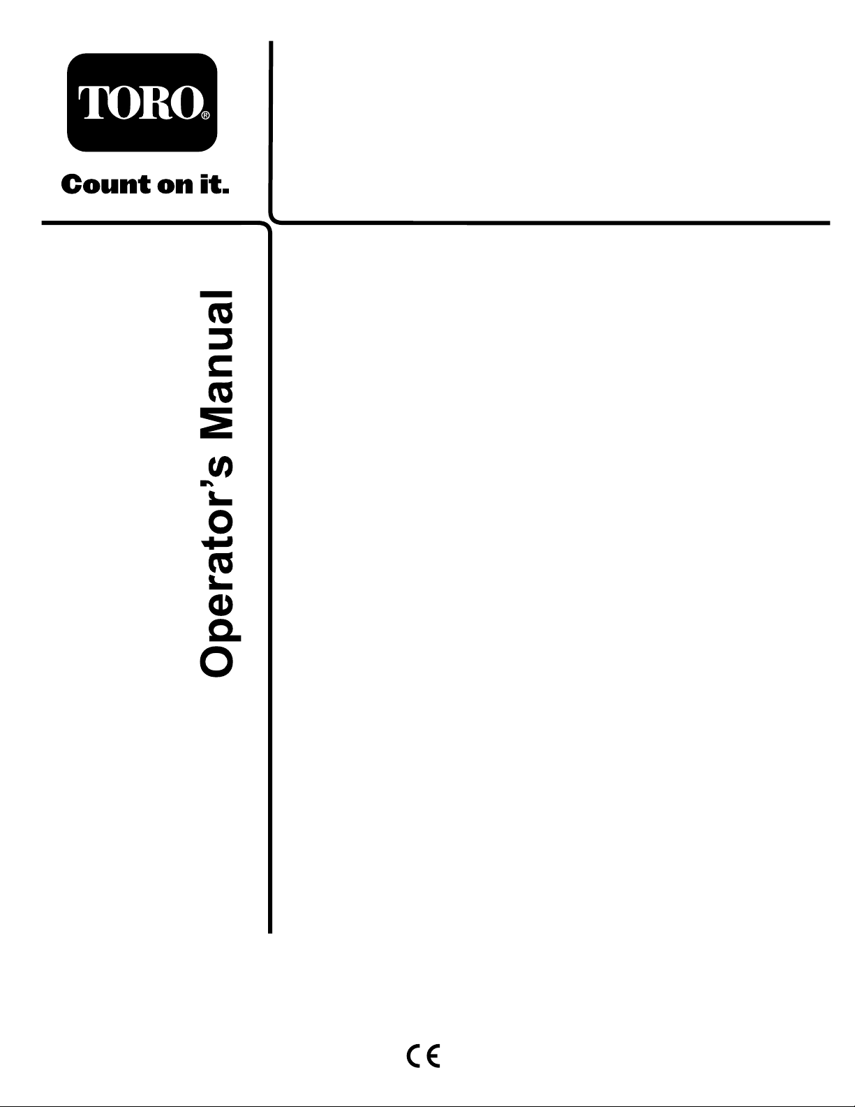
SafetyandInstructionalDecals.
Safetydecalsandinstructionsareeasilyvisibletotheoperatorandarelocatednearanyareaofpotential
danger.Replaceanydecalthatisdamagedorlost.
107-2916
1.Removetheignitionkeyandreadthe
Operator'sManualbeforeservicingor
performingmaintenance.
120-6604
2.Thrownobjecthazard—donotoperate
themowerwiththedeectorupor
removed,keepthedeectorinplace;
keepbystandersasafedistancefrom
themachine.
1.ReadtheOperator's
1.Warning—readtheOperator'sManualforinstructionson
3.Cutting/dismembermenthazardof
handorfoot,mowerblade—stayaway
frommovingparts.
93-6697
Manual.
2.Checktheoilevery50
hours.AddSAE80w-90
(APIGL-5)oilifneeded.
93-7818
torquingthebladebolt/nutto115-149N-m(85-110ft-lb).
1.Thrownobjecthazard—keepbystandersawayfromthe
machine.
2.Cutting/dismembermenthazardofhand,mower
blade—stayawayfrommovingparts,keepallguardsand
shieldsinplace.
3.Cutting/dismembermenthazardoffoot,mowerblade—stay
awayfrommovingparts,keepallguardsandshieldsin
place.
93-6696
1.Storedenergyhazard—readtheOperator'sManual.
92–3035
1.Height-of-cut
7
Page 8
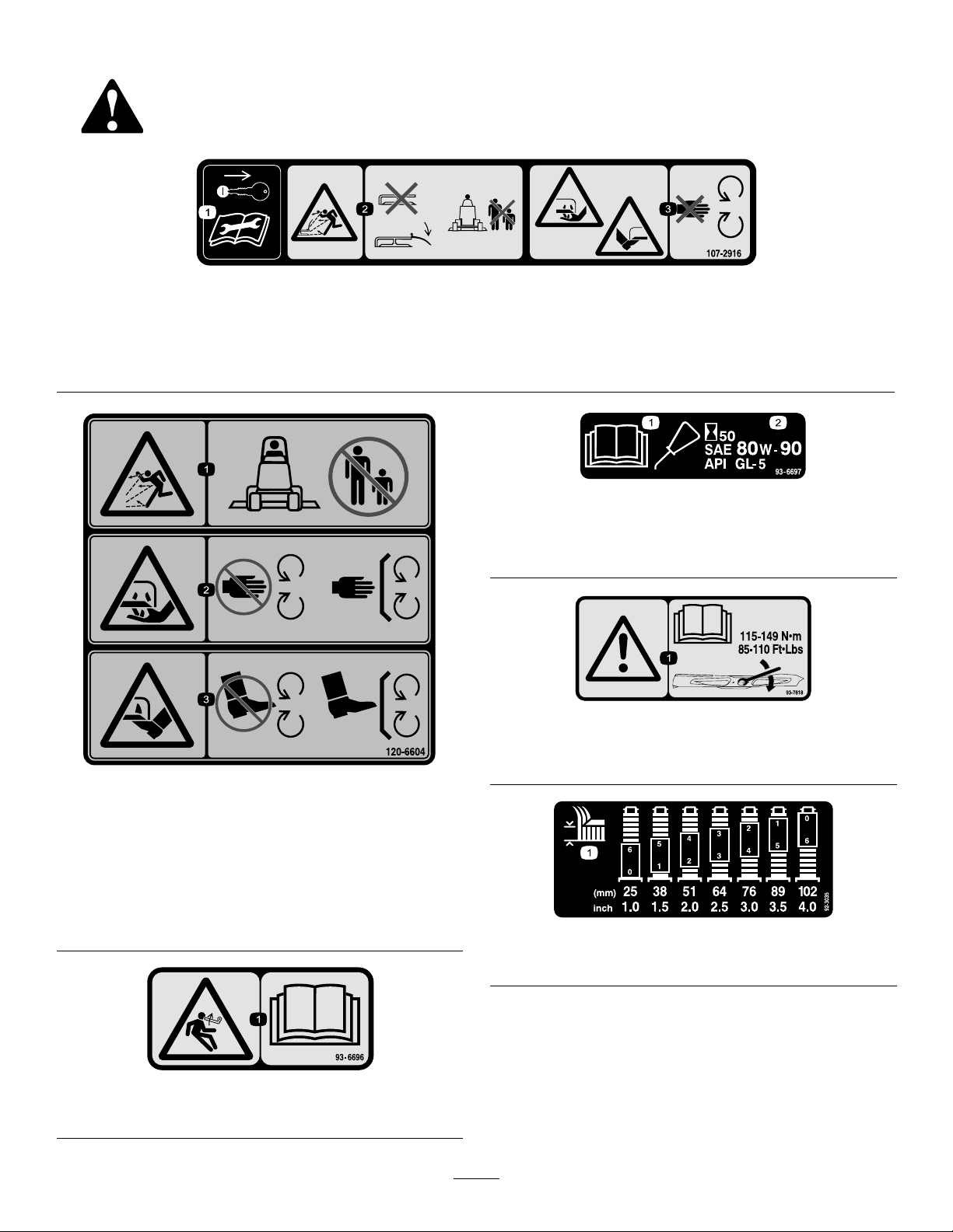
99–5172
117–4979
1.Entanglementhazard,belt—stayawayfrommovingparts,
keepallguardsandshieldsinplace.
107-2915
1.Entanglementhazard,shaft-keepbystandersasafe
distancefromthemachine.
107-2926
1.Cutting/dismembermenthazard,impeller—stayawayfrom
movingparts.
2.Thrownobjecthazard—keepbystandersasafedistance
fromthemachine.
105–9553
1.Warning—readtheOperator'sManual.
2.Tippinghazard—lowerthecuttingunitwhendrivingdown
slopes.For2wheeldriveunits,adda25kg(55lb.)rear
weighttoGM228Dunitsanda48kg(105lb.)rearweight
toGM225units.For4wheeldriveunits,donotaddweight.
107-2908
1.Thrownobjecthazard—keepbystandersasafedistance
fromthemachine.
2.Thrownobjecthazard—donotoperatethemowerwiththe
deectoruporremoved,keepthedeectorinplace.
3.Cutting/dismembermenthazardofhandorfoot,mower
blade—stayawayfrommovingparts.
93–7301
1.Warning-readtheOperator'sManual.
2.Thrownobjecthazard-stayawayfrommovingparts;keep
allguardsandshieldsinplace.
8
Page 9
Setup
LooseParts
Usethechartbelowtoverifythatallpartshavebeenshipped.
ProcedureDescription
1
2
3
4
5
MediaandAdditionalParts
Description
PartsCatalog
Operator'sManual
Frontcastorwheelassembly2
Rearcastorwheelassembly2
Right-handliftarm
Left-handliftarm
Pivotpin2
Cotterpin(5/32x1-3/4inches)
Nopartsrequired
Nopartsrequired
Nopartsrequired
Qty.
1
1
Reviewthematerialandsaveinanappropriateplace:
Qty.
Use
Installthecastorwheelassemblies.
1
1
2
–
–
–
Installtheliftarms.
Connecttheliftarmstothecuttingunit.
MountthePTOshaftguardandconnect
thePTOshafttothecuttingunitgear
box.
Installtherearweight.
Use
DANGER
IftheengineisstartedandthePTOshaftisallowed
torotate,seriousinjurycouldresult.
DonotstarttheengineandengagethePTOlever
whenthePTOshaftisnotconnectedtothegear
boxonthecuttingunit.
Note:Determinetheleftandrightsidesofthemachine
fromthenormaloperatingposition.
Note:Wheninstallingthe62inchdeckontoa
Groundsmaster200Seriestractionunit,theWeightTransfer
Kit,T oroPartNumber70-8100mustbeinstalled.
1
InstallingtheCastorWheel Assemblies
Partsneededforthisprocedure:
2Frontcastorwheelassembly
2Rearcastorwheelassembly
Procedure
Thethrustwashers,spacers,andtensioningcapshavebeen
installedonthecastorwheelspindlesforshipping.
1.Removethetensioningcapsfromthespindleshafts
andslideoffthespacersandthrustwashers(Figure
2andFigure3).
9
Page 10

Figure2
FrontCastorWheelAssembly
1.Tensioningcap
2.Thrustwashers4.Frontcastorspindle
3.Spacers
3.Slideathrustwasherontothespindle,pushtheround
castorspindlethroughthefrontcastorarm,andthe
hexcastorspindlethroughtherearcastorarm.
4.Installanotherthrustwasherandtheremainingspacers
ontothespindleandinstallthetensioningcaptosecure
theassembly.
Important:Thethrustwashers,notthespacers,
mustcontactthetopandbottomofthecastorarm.
5.Ensurethatallfourcastorwheelsaresetatthesame
height-of-cutandrollthecuttingunitoffofthepallet.
2
InstallingtheLiftArms
Partsneededforthisprocedure:
1
Right-handliftarm
1
Left-handliftarm
2Pivotpin
2
Cotterpin(5/32x1-3/4inches)
Procedure
1.Ononesideofthetractionunit,loosen(donot
remove)thewheelnutsthatsecurethewheelandtire
assemblytothefrontwheelstuds.
2.Jackupthemachineuntilthefrontwheelisoffthe
oor.
Figure3
RearCastorWheelAssembly
1.Tensioningcap
2.Thrustwashers4.Rearcastorspindle
2.Slidethespacersontothecastorspindletogetthe
desiredheight-of-cut;refertothechartinAdjusting
theHeight-of-CutintheOperationsection.
3.Spacers
Note:Usejackstandsorblockthemachinetoprevent
itfromaccidentallyfalling.
3.Removethewheelnutsandslidethewheelandtire
assemblyoffthestuds.
4.Mountaliftarm(withtheballjointendpositioned
outward)tothepivotbracketwithapivotpinanda
cotterpin(5/32x1-3/4inches)(Figure4).
Figure4
1.Pivotpin
2.Liftarm
3.Liftarmpivotbracket
4.Brakereturnspring
10
Page 11

5.Mounttherearoftheliftarmtotheliftcylinderwitha
pivotpinand2cotterpins(suppliedwiththetraction
unit).
6.Hookthebrakereturnspringtotheholeinthelift
arm(Figure4).
7.Repeattheprocedureontheoppositesideofthe
machine.
3
ConnectingtheLiftArmsto theCuttingUnit
4.Securetheballjointmountstoeachcastorarmwith
2capscrews(7/16x3inches)andangenuts(7/16
inches)(Figure6).
NoPartsRequired
Procedure
1.Movethecuttingunitintopositioninfrontofthe
tractionunit.
2.Measurethedistancefromtheendofeachliftarmto
thecenteroftheballjoint(greasetting).Thedistance
shouldbe2-1/4inches(57mm)(Figure5).
Note:Ifthedistanceisnot2-1/4inches(57mm),
loosenthejamnutthatsecurestheballjointtothelift
armandrotatetheballjointinoroutuntilthedistance
isattained.Donottightenthejamnutsatthistime.
Figure6
1.Castorarm4.Capscrew
2.Balljointmount5.Flangenut
3.Balljoint
Note:Theballjointmountshouldbeabovethecastor
armwhenitisassembled.
5.Tightenthelargejamnutthatsecurestheballjointto
theliftarm(Figure6).
Note:Whentighteningthejamnut,holdtheballjoint
straighttopermitproperoscillationduringraisingand
loweringofthecuttingunit.
4
MountingthePTOShaftGuard andConnectingthePTOShaft totheCuttingUnitGearBox
Figure5
1.Liftarm
2.Balljoint
3.MovetheliftlevertotheFloatposition.Pushthelift
armsdownuntiltheholesintheballjointmounts
lineupwiththeholesinthecastorarms.
Note:OntheGroundsmaster3280–Dand3320the
enginemustberunningtolowertheliftarms.
3.Jamnut
4.2–1/4inch(57mm)
NoPartsRequired
Procedure
1.Removethe2capscrewsandlockwashersthatsecure
thePTOguardmountingbracketstothegearbox
(Figure7).
11
Page 12

Figure7
1.PTOguard2.Gearbox
Note:Retainthefastenersforfutureinstallation.
2.SlidethePTOshaftguardontothePTOshaft,
positioningtheguardasshowninFigure7.
3.SlidethemalePTOshaftintothefemalePTOshaft.
Note:Alignthemountingholesinthegearcaseinput
shaftwiththeholesinthePTOshaftandslidethem
together.
4.Securethemwitharollpin.
TwoWheelDriveGroundsmaster3280-Dand
Groundsmaster3320tractionunitswithserialnumbers
260000101andupdonotneedadditionalrearweightto
complywithCENstandardEN836:1997,ISOstandard
5395:1990andtheANSIB71.4-2012Standard.
FourWheelDriveGroundsmaster3280-Dtractionunits
donotneedadditionalrearweighttocomplywithCEN
standardEN836:1997,ISOstandard5395:1990andthe
ANSIB71.4-2012Standard.
5.Tightenthecapscrewsandnuts.
6.AttachthePTOshaftguardtothegearboxwiththe2
capscrewsandlockwasherspreviouslyremoved.
5
InstallingtheRearWeight
NoPartsRequired
Procedure
TwoWheelDriveGroundsmaster1000and200Series
tractionunitscomplywithCENstandardEN836:1997,ISO
standard5395:1990andtheANSIB71.4-2012Standardwhen
equippedwithrearweight.Refertothechartinthetraction
unitOperator’sManualtodeterminethecombinationsof
weightrequired.OrderthepartsfromyourlocalAuthorized
ToroDistributor.
FourWheelDriveGroundsmaster200Seriestractionunits
donotneedadditionalrearweighttocomplywithCEN
standardEN836:1997,ISOstandard5395:1990andthe
ANSIB71.4-2012Standard.
TwoWheelDriveGroundsmaster3280-Dand
Groundsmaster3320tractionunitswithserialnumbers
250000101through259999999complywithCEN
standardEN836:1997,ISOstandard5395:1990andthe
ANSIB71.4-2012Standardwhenequippedwiththerear
weightkit,partnumber24-5780.
12
Page 13

ProductOverview
Operation
Specications.
Note:Specicationsanddesignaresubjecttochange
withoutnotice.
Width
ofCut
Height
ofCut
Blade
Tip
Speed
Cutting
Blades
Castor
Wheels
Drive
System
Net
Weight
Attachments/Accessories
AselectionofToroapprovedattachmentsandaccessoriesis
availableforusewiththemachinetoenhanceandexpand
itscapabilities.ContactyourAuthorizedServiceDealeror
Distributororgotowww .T oro.comforalistofallapproved
attachmentsandaccessories.
1.56m(61-5/8inches)
Adjustablefrom25to102mm(1to4inches)in13
mm(1/2inch)increments
15,480ft/minute@3250engineRPM
3heat-treatedsteelblades,each4.8mm(3/16inch)
thickand55cm(24-3/4inches)long
203mm(8inch)diametergreaseablerollerbearings
(inatedto241-345kPa[35-50psi])
PTOdrivengearboxtransmitspowerthrougha"AA"
sectionbelttoallbladespindles.
244kg(539lb)
Note:Determinetheleftandrightsidesofthemachine
fromthenormaloperatingposition.
AdjustingtheHeight-of-Cut
Theheight-of-cutisadjustablefrom25to102mm(1to
4inches)in13mm(1/2inch)increments,byaddingor
removinganequalnumberofspacersonthefrontand
rearcastorforks.Theheight-of-cutchartbelowgivesthe
combinationsofspacerstouseforallheight-of-cutsettings.
Setting
25mm(1inch)
38mm(1-1/2
inches)
51mm(2inches)
64mm(2-1/2
inches)
76mm(3inches)
89mm(3-1/2
inches)
102mm(4inches)
1.Starttheengineandraisethecuttingunitsothatthe
height-of-cutcanbechanged.
2.Stoptheengineafterthecuttingunitisraised.
SpacersBelowCastorArm Height-of-Cut
FrontRear
00
11
22
33
44
55
66
AdjustingtheFrontCastorWheels
1.Removethetensioningcapfromthespindleshaftand
slidethespindleoutofthefrontcastorarm(Figure8).
Figure8
1.Frontcastorwheel
2.Tensioningcap4.Thrustwashers
3.Spacers
13
Page 14

2.Removethewasherfromthespindleshaft.
3.Slidethespacersontothespindleshafttogetthe
desiredheight-of-cut,thenslidethewasherontothe
shaft.
4.Pushthecastorspindlethroughthefrontcastorarm.
5.Installtheotherthrustwasherandremainingspacers
ontothespindle.
6.Installthetensioningcaptosecuretheassembly.
AdjustingtheRearCastorWheels
1.Removethetensioningcapsecuringthegagewheelto
thecuttingunitbrackets(Figure9).
AdjustingtheRollersand GageWheel
Note:Ifthecuttingunitistobeusedinthe25mm(1inch)
or38mm(1-1/2inches)height-of-cutsetting,thecutting
unitrollersmustberepositionedinthetopbracketholes.
AdjustingtheFrontRoller
1.Removethecapscrewandnutsecuringtherollershaft
tothecuttingunitbracket(Figure10).
Figure9
1.Rearcastorwheel
2.Tensioningcap4.Thrustwashers
2.Removeoradd”C”shapedspacersatthenarrow
portionofthespindleshaft,belowthecastorarm,to
getthedesiredheight-of-cut.
Note:Ensurethatthethrustwashers,notthespacers,
contactthetopandbottomofthecastorarm.
3.Installthetensioningcaptosecuretheassembly.
Note:Ensurethatallfourcastorwheelsaresetatthe
sameheight-of-cut.
3.Spacers
Figure10
1.Externalroller
2.Slidetheshaftoutofthelowerbracketholes,alignthe
rollerwiththetopholes,andinstalltheshaft.
3.Securetherollershafttothecuttingunitbracketwith
thecapscrewandnut.
2.Rollershaft
AdjustingtheFrontGageWheel
1.Removethecapscrewandnutsecuringthegagewheel
tothecuttingunitbrackets(Figure11).
Figure11
1.Gagewheel
2.Aligntherollerandspacerwiththetopholesinthe
bracketsandsecurethemwiththecapscrewandnut.
14
Page 15

AdjustingtheRear(Internal)Rollers
1.Removethecotterpinssecuringtherollershaftstothe
bracketsontheundersideofthedeck(Figure12).
GreasingtheCuttingUnit
Beforethecuttingunitisoperated,itmustbegreasedto
ensureproperlubricatingcharacteristics;refertoLubrication
SectionofManual.Failuretoproperlygreasethecuttingunit
willresultinprematurefailureofcriticalparts.
AdjustingtheWeightTransfer
OnGroundsmaster3280-Dand3320modelsonly,referto
thetractionunitOperator'sManualfortheproceduretoadjust
thecounterbalancepressureforbestperformance.
UsingtheGrassDeector
Figure12
1.Internalrollers
2.Slidetheshaftsoutofthelowerbracketholes,alignthe
rollerswiththetopholes,andinstalltheshafts.
3.Installthecotterpinstosecuretheassemblies.
CheckingtheGearBox Lubricant
ThegearboxisdesignedtooperateonSAE80-90wt.gear
lube.Althoughthegearboxisshippedwithlubricantfrom
thefactory,checkthelevelbeforeoperatingthecuttingunit.
1.Positionthemachineandcuttingunitonalevelsurface.
2.Removethedipstick/llplugfromthetopofthegear
box(Figure13)andensurethatthelubricantisbetween
themarksonthedipstick.Ifthelubricantlevelislow ,
addenoughlubricantuntilthelevelisbetweenthe
marks.
DANGER
Withoutthegrassdeectormountedinplace,you
andothersareexposedtobladecontactandthrown
debris.Contactwiththerotatingmowerblade(s)
andthrowndebriswillcauseinjuryordeath.
•Neverremovethegrassdeectorfromthemower
becausethegrassdeectorroutesmaterialdown
towardtheturf.Ifthegrassdeectorisever
damaged,replaceitimmediately .
•Neverputyourhandsorfeetunderthemower.
•Neveroperatethemowerwiththedeector
removedfromthecuttingunitortied/blocked
inaraisedposition.
Note:Thedeectorisspringloadedintoitsdownward
normaloperatingposition(Figure14),buttheoperatorcan
temporarilyswingitoutofthewaytofacilitateloadingina
trailerorwhenotherwisenecessary.
1.Dipstick/llplug
Figure13
Figure14
1.Grassdeector2.Springhinges
15
Page 16

Maintenance
Lubrication
Thecuttingunitmustbelubricatedregularly.Ifthemachine
isoperatedundernormalconditions,lubricatethecastor
bearingsandbushingswithNo.2generalpurposelithium
basegreaseormolybdenumbasegreaseafterevery8hoursof
operationordaily,whichevercomesrst.Allotherbearings,
bushings,andthegearboxmustbelubricatedafterevery50
hoursofoperation.
1.Lubricatethefollowingareas:
•Bladespindlebearings(Figure17)
Figure17
•Frontcastorspindlebushings(Figure15)
•Frontandrearcastorwheelbearings(Figure15)
Figure15
•Rightandleftliftarmpivotpins(Figure16)
•Rightandleftpusharmballjoints(Figure17)
2.Positionthemachineandcuttingunitonalevelsurface
andlowerthecuttingunit.
3.Removethedipstick/llplugfromthetopofthegear
box(Figure18)andensurethatthelubricantisbetween
themarksonthedipstick.
Note:Ifthelubricantlevelislow,addSAE80-90wt.
gearlubeuntilthelevelisbetweenthemarks.
AlternativeSyntheticOil:MobilubeSHC75W -90
Figure16
Figure18
1.Fill/checkplug
SeparatingtheCuttingUnit fromtheTractionUnit
1.Positionthemachineonalevelsurface.
2.Raisethecuttingunit,engagetheparkingbrake,put
thetractionpedalinneutral,setthePTOleverinthe
Offposition,shuttheengineoff,andremovethe
ignitionkey .
3.Positionthemachineonalevelsurface,lowerthe
cuttingunittotheoor,movetheliftlevertotheoat
position,shuttheengineoff,andengagetheparking
brake.
16
Page 17

4.Removethecapscrewsandlocknutssecuringtheball
jointmountstothecastorarmsonthecuttingunit
(Figure19).
Figure19
1.Castorarm
5.Rollthecuttingunitawayfromthetractionunit,
separatingthemaleandfemalesectionsofthePTO
shaft(Figure20).
2.Balljointmount
DANGER
IftheengineisstartedandthePTOshaftis
allowedtorotate,seriousinjurycouldresult.
DonotstarttheengineandengagethePTO
leverwhenthePTOshaftisnotconnectedto
thegearboxonthecuttingunit.
4.MovetheliftlevertotheFloatposition.Pushthelift
armsdownuntiltheholesintheballjointmounts
lineupwiththeholesinthecastorarms(Figure19).
5.Securetheballjointmountstothecastorarmswiththe
capscrewsandangenuts.
ServicingtheBushingsinthe CastorArms
Thecastorarmshavebushingspressedintothetopand
bottomportionofthetubewhich,aftermanyhoursof
operation,willwear.Tocheckthebushings,movethecastor
forkbackandforthandfromsidetoside.Ifthecastorshaft
islooseinsidethebushings,thebushingsarewornandmust
bereplaced.
1.Raisethecuttingunitsothatthewheelsareoffthe
oorandblockitsothatitcannotaccidentallyfall.
2.Removethetensioningcap,spacer(s),andthrust
washerfromthetopofthecastorspindle.
3.Pullthecastorspindleoutofthemountingtube.
Allowthethrustwasherandspacer(s)toremainon
thebottomofthespindle.
4.Insertapinpunchintothetoporbottomofthe
mountingtube,anddrivethebushingoutofthetube
(Figure21).Also,drivetheotherbushingoutofthe
tube.
Figure20
1.PTOshaft
MountingtheCuttingUnitto theTractionUnit
1.Positionthemachineonalevelsurfaceandshutthe
engineoff.
2.Movethecuttingunitintopositioninfrontofthe
tractionunit.
3.SlidethemalePTOshaftintothefemalePTOshaft
(Figure20).
Figure21
1.Frontcastorarmtube2.Bushings
5.Cleantheinsideofthemountingtubestoremoveany
dirt.
6.Applygreasetotheinsideandoutsideofthenew
bushings.
7.Useahammerandatplatetodrivethebushingsinto
themountingtube.
8.Inspectthecastorspindleforwear,andreplaceitifit
isdamaged.
9.Pushthecastorshaftthroughthebushingsand
mountingtube.
10.Slidethethrustwasherandspacer(s)ontothespindle.
11.Installthetensioningcaponthecastorspindletoretain
allofthepartsinplace.
17
Page 18

ServicingtheCastorWheels
G010549
andBearings
9.Pushtheotherbushingintotheopenendofthewheel
hubtocaptivatethebearinginsidethewheelhub
(Figure22).
Thecastorwheelrotatesonahigh-qualityrollerbearingand
issupportedbyaspannerbushing.Evenaftermanyhours
ofuse,providedthatthebearingwaskeptwelllubricated,
bearingwearwillbeminimal.However,failingtokeepthe
bearinglubricatedwillcauserapidwear.Awobblycastor
wheelusuallyindicatesawornbearing.
1.Removethelocknutfromthecapscrewholdingthe
castorwheelassemblybetweenthecastorfork(Figure
22).
10.Carefullyslidethespannerthroughthebushingsand
thewheelhub.
11.Installthecastorwheelassemblybetweenthecastor
forkandsecureitinplacewiththecapscrew,washers,
andlocknut.
12.Lubricatethecastorwheelbearingthroughthegrease
tting,usingNo.2generalpurposelithiumbasegrease.
CheckingforaBentBlade
1.Positionthemachineonalevelsurface.
2.Raisethecuttingunit,engagetheparkingbrake,put
thetractionpedalinneutral,thePTOleverintheOff
position,shuttheengineoff,andremovetheignition
key.
3.Blockthecuttingunittopreventitfromaccidentally
falling.
4.Rotatethebladeuntiltheendsfaceforwardand
backward.Measurefromtheinsideofthecuttingunit
tothecuttingedgeatthefrontoftheblade(Figure23),
andrememberthisdimension.
Figure22
1.Castorwheel4.Spannerbushing
2.Capscrewandlocknut
3.Bushing(2)6.Washer(2)
2.Graspthecastorwheelandslidethecapscrewoutof
thefork.
3.Pullthespannerbushingoutofthewheelhub(Figure
22).
4.Removethebushingfromthewheelhubandallow
thebearingtofallout.
5.Removethebushingfromtheoppositesideofthe
wheelhub.
6.Checkthebearing,spanner,andinsideofthewheel
hubforwear,andreplaceanydamagedparts.
7.Toassemblethecastorwheel,pushthebushinginto
thewheelhub.
5.Rollerbearing
Figure23
5.Rotatetheoppositeendofthebladeforward.
6.Measurebetweenthecuttingunitandcuttingedgeof
thebladeatthesamepositionasinstep4
Note:Thedifferencebetweenthedimensions
obtainedinsteps4and5mustnotexceed3mm(1/8
inch).Ifthedimensionexceeds3mm(1/8inch),
replacethebladebecauseitisbent;refertoRemoving
theCuttingBlade.
RemovingtheCuttingBlade
Theblademustbereplacedifasolidobjectishit,the
bladeisout-of-balance,worn,orbent.Alwaysusegenuine
Tororeplacementbladestoensuresafetyandoptimum
performance.Neverusebladesmadebyothermanufacturers
becausetheycouldbedangerous.
8.Slidethebearingintothewheelhub.
18
Page 19

DANGER
G010555
1
2
Awornordamagedbladecanbreak,andapiece
ofthebladecouldbethrownintotheoperator's
orbystander'sarea,resultinginseriouspersonal
injuryordeath.
•Inspectthebladeperiodicallyforwearor
damage.
•Donottrytostraightenabladethatisbent.
•Neverweldabrokenorcrackedblade.
•Replaceawornordamagedbladewitha
newTorobladetoensurecontinuedsafety
certicationoftheproduct.
1.Positionthemachineonalevelsurface.
2.Raisethecuttingunit,engagetheparkingbrake,put
thetractionpedalinneutralandthePTOleverinthe
Offposition,shuttheengineoff,andremovethe
ignitionkey .
3.Blockthecuttingunittopreventitfromaccidentally
falling.
4.Grasptheendofthebladeusingaragorthickly
paddedglove.Removethebladebolt,anti-scalpcup,
andbladefromthespindleshaft(Figure24).
producinganevencut.However,thesailwillgraduallywear
downduringoperation,andthisconditionisnormal.Asthe
sailwearsdown,thequality-of-cutwilldegradesomewhat,
althoughthecuttingedgesaresharp.Thecuttingedgeof
theblademustbesharpsothatthegrassiscutratherthan
torn.Adullcuttingedgeisevidentwhenthetipsofthegrass
appearbrownandshredded.Sharpenthecuttingedgesto
correctthiscondition.
1.Positionthemachineonalevelsurface.
2.Raisethecuttingunit,engagetheparkingbrake,put
thetractionpedalinneutralandthePTOleverinthe
Offposition,shuttheengineoff,andremovethe
ignitionkey .
3.Blockthecuttingunittopreventitfromaccidentally
falling.
4.Examinethecuttingendsofthebladecarefully,
especiallywheretheatandcurvedpartsoftheblade
meet(Figure25).
Note:Sincesandandabrasivematerialcanwearaway
themetalthatconnectstheatandcurvedpartsofthe
blade,checkthebladebeforeusingthemachine.If
younoticewear(Figure25),replacetheblade;referto
RemovingtheCuttingBlade.
Figure24
1.Bladebolt2.Anti-scalpcup
5.Installtheblade(withthesailfacingtowardthecutting
unit),theanti-scalpcup,andthebladebolt.
Note:Tightenthebladeboltto115-149N-m(85-110
ft-lb).
InspectingandSharpeningthe Blade
Twoareasmustbeconsideredwhencheckingandservicing
thecuttingblade:thesailandthecuttingedge.Bothcutting
edgesandthesail,whichistheturnedupportionopposite
thecuttingedge,contributetoagoodquality-of-cut.The
sailisimportantbecauseitpullsgrassupstraight,thereby
Figure25
1.Cuttingedge3.Wear/slotforming
2.Curvedarea/sail4.Crack
WARNING
Ifthebladeisallowedtowear,aslotwillform
betweenthesailandatpartoftheblade
(Figure25).Eventually,apieceoftheblade
maybreakoffandbethrownfromunderthe
housing,possiblyresultinginseriousinjuryto
yourselforbystanders.
•Inspectthebladeperiodicallyforwearor
damage.
•Replaceawornordamagedbladewitha
newT orobladetoensurecontinuedsafety
certicationoftheproduct.
5.Examinethecuttingedgesofallblades,andsharpen
thecuttingedgesiftheyaredullornicked.
19
Page 20

Note:Sharpenonlythetopsideofthecuttingedge
G010556
A
B
C
A
B
C
A
B
C
G010557
1
andmaintaintheoriginalcuttingangletoensure
sharpness(Figure26).Thebladewillremainbalanced
ifthesameamountofmetalisremovedfromboth
cuttingedges.
Figure26
1.Sharpenatoriginalangle
Figure27
Note:Removethebladesandsharpenthemona
grinder;refertoRemovingtheCuttingBlades.
6.Installtheblade,theanti-scalpcup,andthebladebolt.
Note:Thebladesailsmustbeontopoftheblade.
Note:Tightenthebladeboltto115-149N-m(85-110
ft-lb).
CheckingandCorrecting MismatchofBlades
Ifonecuttingbladecutslowerthantheothers,correctthem
asfollows:
1.Lowerthecuttingunitontoalevelsurface,engagethe
parkingbrake,putthetractionpedalinneutralandthe
PTOleverintheOffposition,shuttheengineoff,and
removetheignitionkey.
2.Ensurethatthetirepressureisequalonalltires.
3.Raisetheheight-of-cuttothe102mm(4inches)
position;refertoAdjustingtheHeight-of-Cut.
4.Rotatethebladessothatthetipslineupwithone
another.
Note:Thetipsoftheadjacentbladesmustbewithin3
mm(1/8inch)ofeachother.Ifthetipsarenotwithin
3mm(1/8inch)ofeachother,proceedtostep10and
addshimsbetweenthespindlehousingandbottom
ofthecuttingunit.
5.Ensurethatthefrontheight-of-cutpinsareresting
properlyontheframecushions.Ifthepinsarenot
restingproperly,placeashimorshimsunderthe
cushiontoraiseitforproperalignment.
6.Positionall3bladesintheAposition(Figure27),
andmeasurefromthelevelsurfacetothebottomof
thetipendofeachblade(Figure28),andnotethe
measurement.
Figure28
1.Measurefromthebladetiptoalevelsurface.
7.RotatethebladestotheBposition(Figure27),measure
thedistanceofallofthebladestothelevelsurface,and
notethedimensions(Figure28).
8.RotatethebladestotheCposition,measure,andnote
thedistancemeasured(Figure27andFigure28).
9.Comparethemeasurementsatthevariouspositions.
Note:Alldimensionsmustbeequalwithin6mm
(1/4inch)fromany2adjacentblades.Thedifference
betweenthedimensionsofall3bladesmustnot
exceed10mm(3/8inch).Ifthedifferenceexceeds
specications,proceedtostep10.
10.Removethecapscrews,atwashers,andlocknutsfrom
theouterspindleintheareawheretheshimsmustbe
added.
Note:Toraiseorlowertheblade,addashim,Part
No.3256-24,betweenthespindlehousingandbottom
ofthecuttingunit.
11.Continuecheckingthealignmentofthebladesand
addingshimsuntilthetipsofthebladesarewithinthe
requireddimension.
ReplacingtheGrassDeector
1.Positionthemachineonalevelsurface.
2.Raisethecuttingunit,engagetheparkingbrake,put
thetractionpedalinneutralandthePTOleverinthe
Offposition,shuttheengineoff,andremovethe
ignitionkey .
3.Blockthecuttingunittopreventitfromaccidentally
falling.
4.Removethe2capscrews,locknuts,andspringsthat
securethedeectormountstothepivotbrackets
(Figure29).
20
Page 21

Figure29
1.Bolt3.Pivotbrackets
2.Locknuts
5.Toremovethepivotbrackets,removethecarriage
boltsandnuts(Figure29).
6.Installthepivotbracketsontopofthedischarge
openingwiththecarriageboltsandnuts.
Note:Theheadofthecarriageboltsmustbeonthe
insideofthecuttingunit.
4.Spring
position,shuttheengineoff,andremovetheignition
key.
3.Removethecoverfromthecentercuttingunit.
4.Loosenthe2nutsthatsecuretheidlerplateinplace.
5.Useasocketandtorquewrenchtotightentheidler
adjustingnutto47to54N-m(35to40ft-lb)(Figure
30).
Figure30
1.Idlerplate3.Idleradjustingnut
2.Nuts(2)
7.Positionthedeectormountsonthepivotbrackets
andsecurethepartstogetherwiththecapscrews,
locknuts,andsprings.
Note:Bothlocknutsmustfaceeachother.Tightenthe
locknutsuntiltheyareushagainstthedeectorpivots.
8.Liftthedeectorandallowittodroptocheckthe
springtension.
Note:Thedeectormustbeheldrmlyinthefull
downwardpositionbythespringtension.Correctit
ifnecessary.
AdjustingtheIdlerPulley
Theidlerpulleyappliesforceagainstthebeltsothatpower
canbetransmittedtothebladepulleys.Iftheidlerisnot
tensionedagainstthebeltwithsufcientforce,maximum
powerwillnotbetransmittedtothepulleys.Tensiononthe
beltrequires47to54N-m(35to40ft-lb)oftorqueonthe
largenut,whichappliesforceagainstthebelt.Iftheidleris
notadjustedtothesespecications,adjustit.
Important:Thefastenersonthecoversofthismachine
aredesignedtoremainonthecoverafterremoval.
Loosenallofthefastenersoneachcoverafewturnsso
thatthecoverisloosebutstillattached,thengoback
andloosenthemuntilthecovercomesfree.Thiswill
preventyoufromaccidentallystrippingtheboltsfree
oftheretainers.
1.Positionthemachineonalevelsurface.
6.Holdthetorqueagainstthebeltandtightenthe2nuts
sothattheidlerplateisheldsecurelyinplace.
7.Releasetheidleradjustingnut.
8.Installthecover.
ReplacingtheDriveBelt
Thebladedrivebelt,tensionedbytheadjustableidler,isvery
durable.However,aftermanyhoursofuse,thebeltwillshow
signsofwear.Signsofawornbeltare:squealingwhenbelt
isrotating,bladesslippingwhencuttinggrass,frayededges,
burnmarks,andcracks.Replacethebeltifanyofthese
conditionsareevident.
Important:Thefastenersonthecoversofthismachine
aredesignedtoremainonthecoverafterremoval.
Loosenallofthefastenersoneachcoverafewturnsso
thatthecoverisloosebutstillattached,thengoback
andloosenthemuntilthecovercomesfree.Thiswill
preventyoufromaccidentallystrippingtheboltsfree
oftheretainers.
1.Positionthemachineonalevelsurface.
2.Lowerthecuttingunit,engagetheparkingbrake,put
thetractionpedalinneutralandthePTOleverinthe
Offposition,shuttheengineoff,andremovethe
ignitionkey .
3.Removethecoversfromthetopofthecuttingunit.
2.Lowerthecuttingunit,engagetheparkingbrake,put
thetractionpedalinneutral,thePTOleverintheOff
4.Loosenthe2nutsthatsecuretheidlerplateinplace,
andremovetheoldbeltfromthepulleys.
21
Page 22

5.Toinstallanewbelt,youmustremovethegearboxby
G010560
1
2
removingthe4carriageboltsandlocknutsholdingthe
gearboxbase.
6.Installthenewbeltaroundthegearboxpulley,spindle
pulleys,stationaryidlerpulley,andadjustableidler
pulley(Figure31).
Figure31
1.Adjustableidlerpulley
2.Gearboxpulley
7.Installthegearboxbasewiththecarriageboltsand
locknuts.
8.Useatorquewrenchtoadjustthetensionoftheidler
pulleyagainstthebelt;refertoAdjustingtheIdler
Pulley.
9.Installthecovers.
22
Page 23

Troubleshooting
Problem
Thecuttingunitwillnotcutorcutspoorly.
PossibleCauseCorrectiveAction
1.Thebladesaredull.
2.Oneormorebladesarebentor
damaged.
3.Thespindleboltsareloose.3.Torquethespindleboltsto115to149
4.Thecuttingunitbeltsarelooseor
broken.
5.Thegearboxpulleyisloose.5.Tightenorreplacethepulley.
6.Agearboxshaftisbroken.6.Replaceanybrokenshafts.
7.ThePTObeltisbroken.7.ReplacethePTObelt.
8.ThePTOpulleyislooseorbroken.
9.ThePTOshaftisbroken.9.ReplacethePTOshaft.
10.Thepulleyontheengineoutputshaft
islooseorbroken.
1.Sharpentheblades.
2.Replacetheblades.
N-m(85to110ft-lb).
4.Tightenorreplacethebeltsas
necessary.
8.Tightenorreplacethepulley.
10.Tightenorreplacethepulley.
23
Page 24

Notes:
24
Page 25

Notes:
25
Page 26

Notes:
26
Page 27

DeclarationofIncorporation
TheT oroCompany,8111LyndaleAve.South,Bloomington,MN,USAdeclaresthatthefollowingunit(s)
conform(s)tothedirectiveslisted,wheninstalledinaccordancewiththeaccompanyinginstructionsontocertain
ToromodelsasindicatedontherelevantDeclarationsofConformity.
ModelNo.
30551314000001andUp
SerialNo.
ProductDescriptionInvoiceDescription
62inSideDischargeMower
GeneralDescription
62”SIDEDISCHARGE
MOWER
62inSideDischargeMower
Directive
2006/42/EC,
2000/14/EC
RelevanttechnicaldocumentationhasbeencompiledasrequiredperPartBofAnnexVIIof2006/42/EC.
Wewillundertaketotransmit,inresponsetorequestsbynationalauthorities,relevantinformationonthispartly
completedmachinery.Themethodoftransmissionshallbeelectronictransmittal.
ThismachineryshallnotbeputintoserviceuntilincorporatedintoapprovedToromodelsasindicatedonthe
associatedDeclarationofConformityandinaccordancewithallinstructions,wherebyitcanbedeclaredin
conformitywithallrelevantDirectives.
Certied:EUTechnicalContact:
PeterT etteroo
ToroEuropeNV
B-2260Oevel-Westerloo
Belgium
DavidKlisTel.003214562960
Sr.EngineeringManager
811 1LyndaleAve.South
Bloomington,MN55420,USA
September26,2013
Fax003214581911
27
Page 28

TheToroTotalCoverageGuarantee
ALimitedWarranty
ConditionsandProductsCovered
TheToroCompanyanditsafliate,ToroWarrantyCompany,pursuant
toanagreementbetweenthem,jointlywarrantyourT oroCommercial
product(“Product”)tobefreefromdefectsinmaterialsorworkmanship
fortwoyearsor1500operationalhours*,whicheveroccursrst.This
warrantyisapplicabletoallproductswiththeexceptionofAerators
(refertoseparatewarrantystatementsfortheseproducts).Wherea
warrantableconditionexists,wewillrepairtheProductatnocosttoyou
includingdiagnostics,labor,parts,andtransportation.Thiswarranty
beginsonthedatetheProductisdeliveredtotheoriginalretailpurchaser.
*Productequippedwithanhourmeter.
InstructionsforObtainingWarrantyService
YouareresponsiblefornotifyingtheCommercialProductsDistributoror
AuthorizedCommercialProductsDealerfromwhomyoupurchasedthe
Productassoonasyoubelieveawarrantableconditionexists.Ifyouneed
helplocatingaCommercialProductsDistributororAuthorizedDealer,or
ifyouhavequestionsregardingyourwarrantyrightsorresponsibilities,
youmaycontactusat:
ToroCommercialProductsServiceDepartment
ToroWarrantyCompany
811 1LyndaleAvenueSouth
Bloomington,MN55420-1196
952–888–8801or800–952–2740
E-mail:commercial.warranty@toro.com
OwnerResponsibilities
AstheProductowner,youareresponsibleforrequiredmaintenanceand
adjustmentsstatedinyourOperator'sManual.Failuretoperformrequired
maintenanceandadjustmentscanbegroundsfordisallowingawarranty
claim.
ItemsandConditionsNotCovered
Notallproductfailuresormalfunctionsthatoccurduringthewarranty
periodaredefectsinmaterialsorworkmanship.Thiswarrantydoesnot
coverthefollowing:
•Productfailureswhichresultfromtheuseofnon-T ororeplacement
parts,orfrominstallationanduseofadd-on,ormodiednon-Toro
brandedaccessoriesandproducts.Aseparatewarrantymaybe
providedbythemanufactureroftheseitems.
•Productfailureswhichresultfromfailuretoperformrecommended
maintenanceand/oradjustments.Failuretoproperlymaintainyour
ToroproductpertheRecommendedMaintenancelistedinthe
Operator’sManualcanresultinclaimsforwarrantybeingdenied.
•ProductfailureswhichresultfromoperatingtheProductinanabusive,
negligent,orrecklessmanner.
•Partssubjecttoconsumptionthroughuseunlessfoundtobedefective.
Examplesofpartswhichareconsumed,orusedup,duringnormal
Productoperationinclude,butarenotlimitedto,brakepadsand
linings,clutchlinings,blades,reels,rollersandbearings(sealedor
greasable),bedknives,sparkplugs,castorwheelsandbearings,tires,
lters,belts,andcertainsprayercomponentssuchasdiaphragms,
nozzles,andcheckvalves,etc.
•Failurescausedbyoutsideinuence.Conditionsconsideredtobe
outsideinuenceinclude,butarenotlimitedto,weather,storage
practices,contamination,useofunapprovedfuels,coolants,lubricants,
additives,fertilizers,water,orchemicals,etc.
•Failureorperformanceissuesduetotheuseoffuels(e.g.gasoline,
diesel,orbiodiesel)thatdonotconformtotheirrespectiveindustry
standards.
•Normalnoise,vibration,wearandtear ,anddeterioration.
•Normal“wearandtear”includes,butisnotlimitedto,damagetoseats
duetowearorabrasion,wornpaintedsurfaces,scratcheddecalsor
windows,etc.
Parts
Partsscheduledforreplacementasrequiredmaintenancearewarranted
fortheperiodoftimeuptothescheduledreplacementtimeforthatpart.
Partsreplacedunderthiswarrantyarecoveredforthedurationofthe
originalproductwarrantyandbecomethepropertyofT oro.T orowillmake
thenaldecisionwhethertorepairanyexistingpartorassemblyorreplace
it.T oromayuseremanufacturedpartsforwarrantyrepairs.
DeepCycleandLithium-IonBatteryWarranty:
DeepcycleandLithium-Ionbatterieshaveaspeciedtotalnumberof
kilowatt-hourstheycandeliverduringtheirlifetime.Operating,recharging,
andmaintenancetechniquescanextendorreducetotalbatterylife.Asthe
batteriesinthisproductareconsumed,theamountofusefulworkbetween
chargingintervalswillslowlydecreaseuntilthebatteryiscompletelyworn
out.Replacementofwornoutbatteries,duetonormalconsumption,
istheresponsibilityoftheproductowner.Batteryreplacementmaybe
requiredduringthenormalproductwarrantyperiodatowner’sexpense.
Note:(Lithium-Ionbatteryonly):ALithium-Ionbatteryhasapartonly
proratedwarrantybeginningyear3throughyear5basedonthetime
inserviceandkilowatthoursused.RefertotheOperator'sManualfor
additionalinformation.
MaintenanceisatOwner’sExpense
Enginetune-up,lubrication,cleaningandpolishing,replacementoflters,
coolant,andcompletingrecommendedmaintenancearesomeofthe
normalservicesT oroproductsrequirethatareattheowner’sexpense.
GeneralConditions
RepairbyanAuthorizedToroDistributororDealerisyoursoleremedy
underthiswarranty.
NeitherTheToroCompanynorToroWarrantyCompanyisliablefor
indirect,incidentalorconsequentialdamagesinconnectionwiththe
useoftheToroProductscoveredbythiswarranty,includingany
costorexpenseofprovidingsubstituteequipmentorserviceduring
reasonableperiodsofmalfunctionornon-usependingcompletion
ofrepairsunderthiswarranty.ExceptfortheEmissionswarranty
referencedbelow,ifapplicable,thereisnootherexpresswarranty.All
impliedwarrantiesofmerchantabilityandtnessforusearelimitedto
thedurationofthisexpresswarranty.
Somestatesdonotallowexclusionsofincidentalorconsequential
damages,orlimitationsonhowlonganimpliedwarrantylasts,sotheabove
exclusionsandlimitationsmaynotapplytoyou.Thiswarrantygivesyou
speciclegalrights,andyoumayalsohaveotherrightswhichvaryfrom
statetostate.
Noteregardingenginewarranty:
TheEmissionsControlSystemonyourProductmaybecoveredby
aseparatewarrantymeetingrequirementsestablishedbytheU.S.
EnvironmentalProtectionAgency(EPA)and/ortheCaliforniaAirResources
Board(CARB).Thehourlimitationssetforthabovedonotapplytothe
EmissionsControlSystemWarranty.RefertotheEngineEmissionControl
WarrantyStatementsuppliedwithyourproductorcontainedintheengine
manufacturer’sdocumentationfordetails
CountriesOtherthantheUnitedStatesorCanada
CustomerswhohavepurchasedT oroproductsexportedfromtheUnitedStatesorCanadashouldcontacttheirT oroDistributor(Dealer)toobtain
guaranteepoliciesforyourcountry ,province,orstate.IfforanyreasonyouaredissatisedwithyourDistributor'sserviceorhavedifcultyobtaining
guaranteeinformation,contacttheT oroimporter.
374-0253RevB
 Loading...