

Page 1

62inBlowerKit
Groundsmaster
ModelNo.30506—SerialNo.315000001andUp
®
200/3280-D/3320SeriesSideDischargeMowers
FormNo.3391-800RevA
Operator'sManual
Safety
WARNING
CALIFORNIA
Proposition65Warning
Thisproductcontainsachemicalorchemicals
knowntotheStateofCaliforniatocausecancer,
birthdefects,orreproductiveharm.
ThisproductcomplieswithallrelevantEuropeandirectives.
Fordetails,pleaseseetheDeclarationofIncorporation(DOI)
atthebackofthispublication.
Improperlyusingormaintainingthemachinecanresult
ininjury.Toreducethepotentialforinjury,complywith
thesesafetyinstructionsandalwayspayattentiontothe
safetyalertsymbols,whichmeansCaution,Warning,or
Danger—personalsafetyinstruction.Failuretocomply
withtheinstructionmayresultinpersonalinjuryor
death.
BeforeOperating
•Readandunderstandthecontentsofthismanualbefore
startingandoperatingthemachine.Becomefamiliarwith
allcontrolsandknowhowtostopquickly.
•Neverallowchildrentooperatethemachine.Donot
allowadultstooperatethemachinewithoutproper
instruction.Onlytrainedoperators,skilledinslope
operationandwhohavereadthismanualshouldoperate
thismachine.
•Neveroperatemachinewhenundertheinuenceof
drugsoralcohol.
•Lightningcancausesevereinjuryordeath.Iflightning
isseenorthunderisheardinthearea,donotoperate
themachine;seekshelter.
•Removealldebrisorotherobjectsthatmightbepicked
upandthrownbycutterblades.Keepallbystandersaway
fromtheoperatingarea.
•Keepallshieldsandsafetydevicesinplace.Ifashield,
safetydevice,ordecalisdefectiveordamaged,repairor
replaceitbeforeoperatingmachine.Also,tightenany
loosenuts,bolts,andscrewstoinsuremachineisinsafe
operatingcondition.
•Donotwearloosettingclothingbecauseitcouldget
caughtinmovingparts.Alwayswearlongpantsand
substantial,slip-resistantfootwear.W earingsafetyglasses,
safetyshoes,andahelmetisadvisableandrequiredby
somelocalordinancesandinsuranceregulations.
•Besureinterlockswitchesareadjustedcorrectlysothe
enginecannotbestartedunlessthetractionpedalis
inreleased-neutralposition-andPTOswitchisinthe
disengageposition.
•Fillfueltankbeforestartingtheengine.Avoidspillingany
fuel.Sincefuelisammable,handleitcarefully .
–Useanapprovedfuelcontainer.
–Donotllfueltankwhenengineishotorrunning.
–Donotsmokewhilehandlingfuel.
–Fillfueltankoutdoorsanduptoabout25mm(1
inch)fromthetopofthetank,notthellerneck.
–Wipeupanyspilledfuel.
WhileOperating
•Sitontheseatwhenstartingtheengineandoperating
themachine.
•Alwaysmakesureseatpivotretainingpinisinstalled.
•Beforestartingtheengine:
–Engageparkingbrake.
–MakesuretractionpedalisinneutralandPTOisin
disengageposition.
–Afterengineisstarted,releaseparkingbrakeandkeep
footofftractionpedal.Machinemustnotmove.If
movementisevident,theneutralreturnmechanism
isadjustedincorrectly.Shutengineoffandadjust
untilmachinedoesnotmovewhentractionpedalis
released.
•Donotruntheengineinaconnedareawithout
adequateventilation.Exhaustfumesarehazardousand
couldpossiblybedeadly .
•Maximumseatingcapacityisoneperson.Therefore,
nevercarrypassengers.
•Checkcarefullyforoverheadclearancesbeforedriving
underanyobjects.
•Thegrassdeectororcompleteblowerassemblymust
alwaysbeinstalledoncuttingunit.
•Operatormustbeskilledandtrainedinhowtodriveon
hillsides.Failuretousecautiononslopesorhillsmay
©2015—TheToro®Company
8111LyndaleAvenueSouth
Bloomington,MN55420
Registeratwww.T oro.com.
OriginalInstructions(EN)
PrintedintheUSA.
AllRightsReserved
*3391-800*A
Page 2

causelossofcontrolandvehicletotiporroll,possibly
resultinginpersonalinjuryordeath.
•Traverseslopescarefully.Donotstartorstopsuddenly
whentraversingslopesorwhentravelinguphillor
downhill.
•Ifenginestallsormachinelosesheadwayandcannot
makeittothetopofaslope,donotturnmachinearound.
Alwaysbackslowlystraightdowntheslope.
•Usingthemachinedemandstheoperator'scomplete
attention.Topreventlossofcontrol:
–Operateonlyindaylightorwhenthereisgood
articiallight.
–Driveslowly .
–Avoidsuddenstartsandstops.
–Lookbehindmachinebeforebackingup.
–Watchforholesorotherhiddenhazards.
–Donotdriveclosetoasandtrap,ditch,creek,or
hazard.
–Reducespeedwhenmakingsharpturnsandwhen
turningonahillside.
–Thecuttingdeckmustbeloweredwhengoingdown
slopesforsteeringcontrol.
•Thegrassdeectormustalwaysbeinstalledandinlowest
positiononthecuttingunitwhenblowerassemblyis
removed.Thisproductisdesignedtodriveobjectsinto
thegroundwheretheyloseenergyquicklyingrassyareas.
However,don'ttakeaninjuryrisk!Whenapersonor
petappearsunexpectedlyinornearthemowingarea,
stopmowing.Carelessoperation,combinedwithterrain
angles,ricochets,orimproperlypositionedguards,can
leadtothrownobjectinjuries.Donotresumemowing
untilareaiscleared.
•Neverraisethecuttingunitwhilethebladesorother
partsarerotating.
•Ifcuttingbladesstrikeasolidobjectorthemachine
vibratesabnormally,disengagePTO,movethrottleto
SLOW,setparkingbrake,andshutengineoff.Remove
keyfromswitchtopreventpossibilityofaccidental
starting.Checkcuttingunit,blowerassemblyandtraction
unitfordamageanddefectiveparts.Repairanydamage
beforerestartingtheengineandoperatingthecutting
unit.Assurecuttingunitbladesareingoodconditionand
bladeboltsaretightenedtopropertorquespecications
(SeeCuttingDeckOperator'sManual).
•Ifthecuttingunitdischargeareaorblowerassembly
everplugs,disengagePTOandshutengineoffbefore
removingtheobstruction.
•Tostopmachine,removefootfromthetractionpedal.
Graduallyreversingthetractionpedalcanprovide
additionalbraking.
•Donottouchengine,mufer,oritadjacentshroudwhile
engineisrunningorsoonafterithasstopped.These
areascouldbehotenoughtocauseaburn.
•Lowerthecuttingunittothegroundandremovekey
fromswitchwhenevermachineisleftunattended.
•Beforegettingoftheseat:
–Movetractionpedaltoneutralpositionandremove
footfrompedal.
–SettheparkingbrakeanddisengagethePTO .
–Shuttheengineoffandremovekeyfromignition
switch.Waitforallmovementtostopbeforegetting
offtheseat.
Maintenance
•Removekeyfromignitionswitchtopreventaccidental
startingoftheenginewhenservicing,adjusting,orstoring
themachine.
•Ifmajorrepairsareeverneededorassistanceisdesired,
contactanAuthorizedToroDistributor.
•Toreducepotentialrehazard,keeptheenginefreeof
excessivegrease,grass,leaves,andaccumulationsofdirt.
•Makesuremachineisinsafeoperatingconditionby
keepingnuts,bolts,andscrewstight.Checkallcutting
unitblademountingboltsfrequentlytoassuretheyare
tightenedtopropertorquespecications(SeetheCutting
DeckOperator'sManual).
•Makesureallhydrauliclineconnectorsaretight,andall
hydraulichosesandlinesareingoodconditionbefore
applyingpressuretothesystem.
•Keepbodyandhandsawayfrompinholeleaksornozzles
thatejecthydraulicuidunderhighpressure.Usepaper
orcardboard,nothands,tosearchforleaks.Hydraulic
uidescapingunderpressurecanhavesufcientforceto
penetrateskinandcauseseriousinjury.Ifuidisejected
intotheskin,itmustbesurgicallyremovedwithinafew
hoursbyadoctorfamiliarwiththisformofinjuryor
gangrenemayresult.
•Beforedisconnectingorperforminganyworkonthe
hydraulicsystem,allpressureinsystemmustberelieved
bystoppingengineandloweringimplementtothe
ground.
•Iftheenginemustberunningtoperformmaintenance
oranadjustment,keepclearofPTOshaft,cuttingunit
blades,andothermovingparts.
•Atthetimeofmanufacture,themachineconformedto
safetystandardsineffectforridingmowers.Toensure
optimumperformanceandcontinuedsafetycertication
ofthemachine,usegenuineTOROreplacementparts
andaccessories.Replacementpartsandaccessoriesmade
byothermanufacturersmayresultinnon-conformance
withthesafetystandards,andthewarrantymaybevoided.
2
Page 3
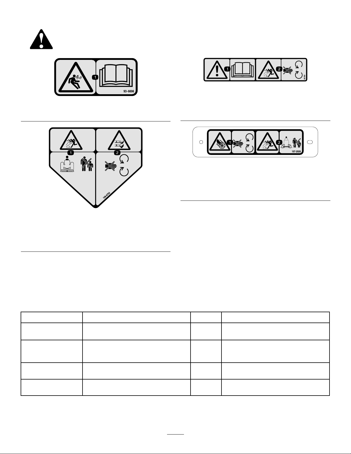
SafetyandInstructionalDecals
Safetydecalsandinstructionsareeasilyvisibletotheoperatorandarelocatednearanyareaofpotential
danger.Replaceanydecalthatisdamagedorlost.
93–7301
93–6696
1.Storedenergyhazard—readtheOperator'sManual.
106-6753
1.Thrownobjecthazard—keepbystandersasafedistance
fromthemachine.
2.Cutting/dismembermenthazardofhandorfoot,mower
blade—stayawayfrommovingparts.
1.Warning-readtheOperator'sManual.
2.Thrownobjecthazard-stayawayfrommovingparts;keep
allguardsandshieldsinplace.
107-2926
1.Cutting/dismembermenthazard,impeller—stayawayfrom
movingparts.
2.Thrownobjecthazard—keepbystandersasafedistance
fromthemachine.
Setup
LooseParts
Usethechartbelowtoverifythatallpartshavebeenshipped.
ProcedureDescription
1
2
3
4
Nopartsrequired
Doublepulley1
Pulleynut1
Nutcover1
Blade3Installthenewblades.
Pivotbrackets2
Qty.
–
3
Removethecuttingunitfromtraction
unit.
Installthenewspindlepulley .
Removeandmodifythegrassdeector.
Use
Page 4

ProcedureDescription
5
6
7
8
Blowerassemblywithmounting
brackets
Capscrew,5/16x1inch
Locknut,5/16
Carriagebolt,3/8inchx3/4inch
Flangenut,3/8inch
Frontdeector
Reardeector
Rearshelf
Leftshelf
Rightshelf
Capscrew,5/16x5/8inch
Locknut,5/16inch
Capscrew,3/8x1inch
Lockwasher,3/8inch
Capscrew,1/4x1inch
Capscrew,1/4x3/4inch
Locknut,1/4inch
Deectorstop
Capscrew,1/4x3/4inch
Locknut,1/4inch
Idlerarmassembly1
Pivotscrew1
Bushing1
Washer2
Locknut,3/8inch
Spring
Threadedrod1
Flangenut,5/16inch
Springbracket
Capscrew,1/4x1inch
Locknut,1/4inch
Qty.
Use
1
3
4
4
3
1
1
1
1
1
6
6
4
4
3
3
6
1
2
2
1
1
2
1
2
2
Installtheblowermountingbrackets.
Installthedeckdeectors.
Mountthenewdeectorstop.
Mounttheidlerassembly.
9
10
11
12
13
14
15
16
Belt1Mounttheblower.
Bumper1
Capscrew,5/16x3inch
Locknut,5/16inch
Trimmolding1
Deckcover1
Beltguard1
Pulleyguard1
Counterbalancespring
Nopartsrequired
Decal,danger1Installthenewdecal.
Chuteassembly
4
4
4
1Installthenewcounterbalancespring.
–
1Mounttheblowerhousingchute.
Installbumper
Installthenewdeckcover.
Installthenewsafetyguards.
Installthecuttingunittothetractionunit.
Page 5
MediaandAdditionalParts
Description
Installationinstructions1
Partscatalog1
Certicateofcompliance
1
RemovingtheCuttingUnit fromtheTractionUnit
NoPartsRequired
Procedure
1.Positionthemachineonalevelsurface,raisethe
cuttingunit,engagetheparkingbrake,ensurethatthe
tractionpedalisintheneutralpositionandthePTO
leverintheOffposition,stoptheengine,andremove
thekeyfromtheswitch.
Qty.
Use
Readbeforeinstallation
Usetoreferencepartnumbers
1
CEcertication
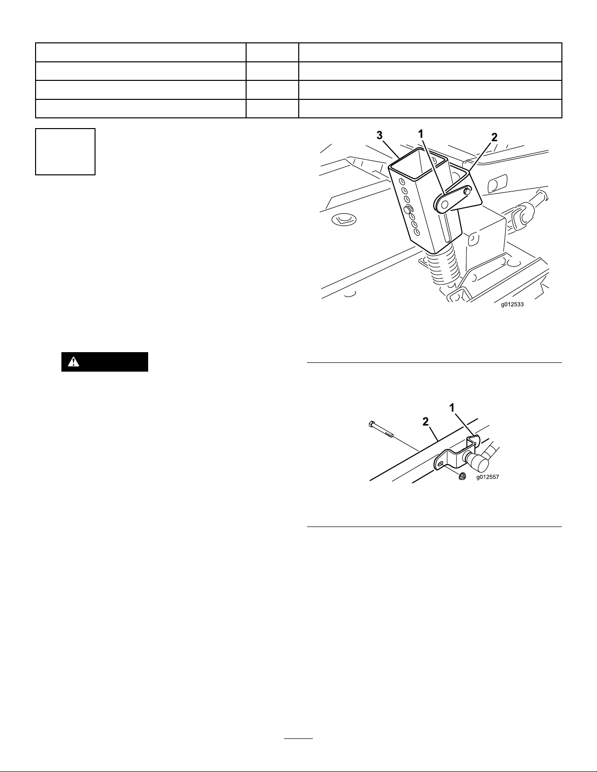
1.Lockpin
2.Bracket
Figure1
3.Springtensionassembly
CAUTION
Thecounterbalancespringisintensionwhen
thedeckisinthelowerposition(200series
tractionunitsonly).
Alwaysraisethedeckbeforeadjustingor
removingthespring.
2.On200seriestractionunitsonly,disconnectthe
counterbalancefromthetractionunit,removethelock
pinsfromthebrackets,separatethespringtension
assembliesfromthebrackets,andlaythemdownon
thedeck.Looselysecurethelockpinstothebrackets
topreventlosingthem(Figure1).
3.Lowerthecuttingunitandremovethe4boltsandnuts
securingliftarmbracketstocastorarms(Figure2).
Figure2
1.Liftarmbracket
4.Starttheengineandraisethetractionunitliftarms.
5.Stoptheengineandslidethecuttingunitawayfromthe
tractionunit,separatingthemaleandfemalesections
ofPTOshaft(Figure3).
2.Rightcastorarm
5
Page 6
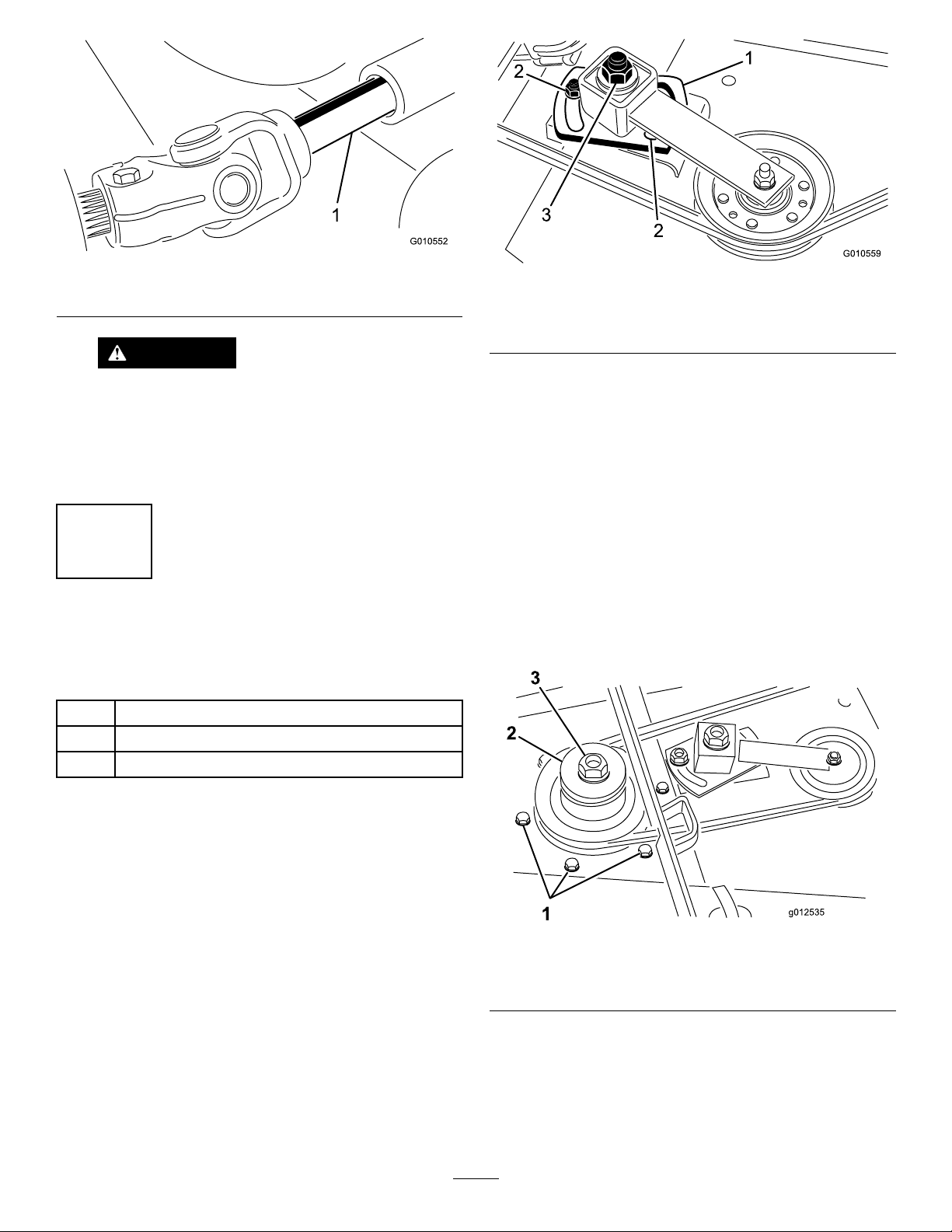
Figure3
1.PTOshaft
CAUTION
IftheengineisstartedandthePTOshaftis
allowedtorotate,seriousinjurycouldresult.
DonotstarttheengineandengagethePTO
leverwhenthePTOshaftisnotconnectedto
thegearboxonthecuttingunit.
2
Figure4
1.Idlerplate3.Idleradjustingnut
2.Nut(2)
3.Removethebeltfromtherightspindlepulley(Figure
4).
4.Removethesixcarriageboltsandangenutssecuring
thespindlehousingassemblytothecuttingunit(Figure
5).Slidethespindlehousingassemblyoutofthe
bottomofthecuttingunit.
5.Removethenutandwasherretainingthepulleyonthe
spindleshaft.Removethepulleyfromtheshaft.
6.Slidethenewdoublespindlepulleyontothespindle
shaft.Donotinstallthepulleynutatthistime.
InstallingtheNewSpindle Pulley
Partsneededforthisprocedure:
1Doublepulley
1Pulleynut
1Nutcover
Procedure
1.Unhookthelatchessecuringtherightcovertothetop
ofthecuttingunit.Removethecoverfromthecutting
unit.
2.Loosenthe2nutssecuringtheidlerplatesothetension
oftheidlerpulleyagainstthebeltisreleased(Figure4).
7.Slidethepulleyendofspindlehousingassembly
throughtheholeinthecuttingunit,andloopthe
beltaroundthepulleyandidler.Mountthespindle
assemblyinplacewith6carriageboltsandangenuts.
Figure5
1.Carriagebolts
2.Doublespindlepulley
8.Installtheoriginalwasherandnewpulleynutontothe
spindleshaftandtightenitto100ft-lb(135.5N-m).
Installthenutcover.
3.Pulleynut
9.Adjust(tighten)theidleradjustingnutto35to40ft-lb
(48to54N-m)toachievetheproperbelttension.
Tightentheidlerplatenuts.
6
Page 7

3
G010555
1
2
InstallingtheNewBlades
Partsneededforthisprocedure:
3Blade
Procedure
1.Grasptheendofbladeusingathicklypaddedglove.
Removethebladebolt,anti-scalpcup,andbladefrom
thespindleshaft(Figure6).
2.Removethecarriageboltsandangenutssecuringthe
pivotbracketstothehousing(Figure7).Removethe
pivotbrackets.Retainthefastenersforfutureuse.
3.Removethe2carriagebolts,atwashers,andlocknuts
securingthereinforcementplatetotheundersideof
thehousingandthestiffenerplatetothetopofthe
housing(Figure7).
Figure7
Figure6
1.Bladebolt2.Anti-scalpcup
2.Insequence,installanewblade(sailfacingtowardthe
cuttingunit)andanti-scalpcup.Securethepartsin
placewiththebladebolt.Tightenthebladeboltto85
to110ft-lb(115to149N-m).
3.Repeatthisprocedureonallblades.
4
RemovingandModifyingthe
GrassDeector
Partsneededforthisprocedure:
2Pivotbrackets
1.Grassdeector3.Reinforcementplate
2.Pivotbrackets
4.Usingthebolts,locknuts,andspringspreviously
removed,installthenewpivotbracketstothedeector
mounts(Figure8).Donotovertightenthenuts
becausethebracketsmustbeallowedtopivot.Save
thisassemblyforsidedischargeoperation.
1.Grassdeector
4.Stiffenerplate
Figure8
2.Pivotbrackets
Procedure
1.Removethebolts,locknuts,andspringssecuringthe
deectormountstothepivotbrackets(Figure7).
Removethedeector.
7
Page 8

5
InstallingtheBlowerMounting
Brackets
Partsneededforthisprocedure:
3.Positionthenewreinforcementplateunderthedeck
aligningthemountingholeswiththeholespreviously
usedformountingthegrassdeector(Figure9).
4.Mountthefrontandrearbracketsandreinforcement
platetothedeckwith2previouslyremovedcarriage
bolts(3/8-16x7/8inch)andangenutseach(Figure
9).Theboltheadsmustbeontopofthedeck.
5.Removethe2knobssecuringtheblowertothe
mountingbrackets.Removetheblower.
1Blowerassemblywithmountingbrackets
3
Capscrew,5/16x1inch
4
Locknut,5/16
4
Carriagebolt,3/8inchx3/4inch
3
Flangenut,3/8inch
Procedure
1.Removethefastenerssecuringtherighthanddeck
coverspringlatchtotherightsideofthecuttingdeck
(Figure9).Removeandretainthelatchforfutureuse
withtherighthandcover.
2.Positiontheblowerandmountingbracketsonthe
deck,aligningthemountingholeswiththeholes
previouslyusedformountingthegrassdeector.
Figure9isshownwiththeblowerremovedfromthe
brackets.Makesurethereisnogapbetweentheblower
andcuttingdeck.
6.Usingeachbracketasatemplate,markthelocationand
drill2additional11/32inchdiameterholes.(2holes
fortherearbracketand1forthefrontbracket.Usethe
reinforcementplateforatemplatetodrilloneofthe
11/32inchdiameterholesfortherearbracket.
Note:Usecautionwhendrillingtheholessothatthe
castorarmisnotdamaged.
7.Securethebracketsandreinforcementplatetothedeck
withbolts(5/16-18x3/4inch)andlocknuts(Figure
9).Theboltheadsmustbeontopofthedeck.
8.Mounttheblowerbracetotherearmountingbracket
with2bolts(3/8-16x1inch)andlocknuts(Figure9)
andtothecastorarmwithabolt(3/8-16x1inch).
9.Whenmountingtheliftarmbracketstothecastor
arms,mountothersideoftheblowerbracetothelift
armbracketandtherightcastorarmwiththeboltand
nutpreviouslyremoved.
Figure9
1.Springlatch4.Reinforcementplate
2.Rearmountingbracket5.Blowerbrace
3.Frontmountingbracket
Figure10
1.Liftarmbracket
8
2.Rightcastorarm
Page 9

6
InstallingtheDeckDeectors
Partsneededforthisprocedure:
1
Frontdeector
1
Reardeector
1
Rearshelf
1
Leftshelf
1
Rightshelf
6
Capscrew,5/16x5/8inch
6
Locknut,5/16inch
4
Capscrew,3/8x1inch
4
Lockwasher,3/8inch
3
Capscrew,1/4x1inch
3
Capscrew,1/4x3/4inch
6
Locknut,1/4inch
Figure12
1.Frontdeector4.Leftshelf
2.Reardeector5.Rightshelf
3.Rearshelf
Procedure
1.Insertthefrontdeectorintothedeck,aligningthe
endofthedeectorwiththeedgeofthedischarge
opening(Figure11andFigure12).
Figure11
1.Frontdeector
2.Usingthedeectorasatemplate,markanddrillthree
11/32inchdiameterholesthroughfrontandtopof
deck.
Figure13
1.Reardeector
5.Usingthedeectorasatemplate,markanddrillthree
11/32inchdiameterholesthroughthedeck.
6.Securethedeectortothedeckwith3bolts(5/16-18x
5/8inch)andlocknuts(5/16-18inch).
7.Beforemountingtheleftandrightshelvestothedeck,
youmustgrindtheweldsoffofthebottomedgeofthe
deck.Paintthedeckaftergrinding.
8.Usingtheexistingholes,mounttherearshelftothe
deckwith4bolts(3/8-16x1inch)andlockwashers
(3/8inch)(Figure14).
3.Securethe2frontmountingtabsofdeectortothe
deckwithbolts(5/16-18x5/8inch)andlocknuts
(5/16-18inch).
4.Securethefrontrightcornerofthefrontmounting
bracketandthetoptabofthedeectortothedeck
withabolt(5/16-18x1inch)andlocknut.
9
Page 10

Figure14
1.Rearshelf
9.Aligntheleftshelfwiththeleftendoftherearshelf
andtheedgeofthedeck(Figure12andFigure14).
10.Securetheleftshelftothedeckwith2bolts(1/4-20x1
inch),1bolt(1/4-20x3/4inch),and3locknuts(Figure
15).Positiontheboltheadstotheinsideofthedeck.
Figure15
Figure16
1.Rightshelf
12.Securetherightshelftothedeckwith1bolt(1/4-20
x1inch),2bolts(1/4-20x3/4inch),and3locknuts.
Positiontheboltheadstotheinsideofthedeck.
7
MountingtheNewDeector
Stop
Partsneededforthisprocedure:
1
Deectorstop
2
Capscrew,1/4x3/4inch
2
Locknut,1/4inch
1.Leftshelf
11.Aligntherightshelfwiththerightendoftherearshelf
andtheedgeofthedeck(Figure12andFigure16).
Usingtheleftshelfasatemplate,locate,mark,anddrill
three9/32inchdiameterholesinthedeck.
Procedure
1.Usingthenewdeectorstopasatemplate,setitonthe
originalatdeectorstop(Figure17).Ensurethatthe
newdeectorstopisushatthebottom,contacting
thesideofthedeck,andparallelwiththeoutsideedge
ofthedeectorsupport.
10
Page 11

Figure17
1.Newdeectorstop
2.Markanddrillholes
3.Boltsandlocknuts
2.Locate,markanddrilltwo9/32inchdiameterholes
throughtheolddeectorsupport.
3.Mountthenewdeectorsupporttotheolddeector
stopwith2bolts(1/4-20x3/4inch)andlocknuts
(1/4-20inch),asshowninFigure17.
8
MountingtheIdlerAssembly
Partsneededforthisprocedure:
1Idlerarmassembly
1Pivotscrew
1Bushing
2Washer
1
Locknut,3/8inch
1
Spring
1Threadedrod
2
Flangenut,5/16inch
1
Springbracket
2
Capscrew,1/4x1inch
2
Locknut,1/4inch
Figure18
1.6-13/16inches2.9-1/8inches
2.UsingthedimensionsshowninFigure19,locate,mark,
anddrilla13/16inchdiameterholeandtwo13/32
inchdiameterholesintherightbridgebar.
Figure19
1.5inches
2.1-1/16inches(2)5.13/16inchdiameter
3.1inch
4.13/32inchdiameter(2)
3.Threadaangenut(5/16-18inch)approximately2
inches(5cm)ontothethreadedrod(Figure20).
Procedure
1.UsingthedimensionsshowninFigure18,locate,mark,
anddrilla13/32inchdiameterholeinthedeck.The
dimensionsshownarefromtherightfrontcornerof
thedeckandfromtheedgeofthedischargeopening.
Theblowerbracketsareremovedforclarity.
Figure20
1.Idlerpulleyarm3.Threadedrod
2.Springbracket4.Spring
11
Page 12

4.Inserttheendofthethreadedrodthroughthelarge
holeinthespringbracketandlooselysecureitwith
anotherangenut(5/16-18inch)(Figure20).Donot
tightentheangenuts.
5.Inserttheotherendofthethreadedrodthroughthe
holeinthebridgebarandsecurethespringbracketto
thebridgewith2boltsandlocknuts(Figure20).
6.Hooktheshortloopofthespringintotheholeinthe
threadedrodandthelongloopintheholeintheidler
arm(Figure20).
7.Mounttheidlerpulleyarmtothedeckwiththe
followingparts,inthisorder:apivotscrew(3/8-16
inch),athrustwasher(1/2inch),theidlerarm,athrust
washer(3/8inch),thedeck,andalocknut(3/8-16
inch)(Figure20).(Donottightentheangenutson
thethreadedrodatthistime.Adjustthespringtension
aftertheblowerassemblyandbelthavebeeninstalled.)
Figure21
9
MountingtheBlower
Partsneededforthisprocedure:
1Belt
Procedure
1.Routethebeltaroundthesmalldeckspindlepulley.
2.Slidetheblowerontothemountingbracketalignment
studs(Figure21)whileroutingthebeltaroundthe
blowerpulley.
Note:Iftheblowerdoesnoteasilyslideontothe
mountingbrackets,loosenthealignmentboltsslightly .
3.Securetheblowertothebracketswith2knobs.
4.Adjustthespringlengthto4-7/8inches(12.4cm)for
properbelttensionbyadjustingtheangenutsonthe
threadedrod.
10
InstalltheBumper
Partsneededforthisprocedure:
1Bumper
4
Capscrew,5/16x3inch
4
Locknut,5/16inch
Procedure
1.UsingdimensionsshowninFigure22,locate,markand
drilla11/32inchdiameterholethroughbothwallsof
therightfrontcastorarmbracket.
12
Page 13

Figure22
g029097
1.2-1/2inches2.3/8inch
2.Securethetopmountingholeofthefrontmounting
plateofthebumpertothecastorarmbracketwitha
bolt(5/16-18x3inch)andlocknut(Figure23).
11
InstallingtheNewDeckCover
Partsneededforthisprocedure:
1Trimmolding
1Deckcover
Procedure
1.Insertatrimmoldingontotherightbridgebar,sothe
sideofthespringbracketis10cm(4inches)tothefar
edgeofthetrimmolding(Figure24).
Figure23
1.Bumper
3.Usingbothmountingplatesofthebumperas
templates,locate,mark,anddrill3additional11/32
inchdiameterholesthroughbothwallsofthefrontand
rearcastorarmbrackets.
Figure24
1.Trimmolding3.Bolt
2.Cover
2.Hooktherearofthedeckcover(Figure24)ontothe
rearchannelpinwhilealigningthecovermounting
boltwiththeholeintherightcastorarm.Thecover
istorestonthetrimmolding.Adjustthemoldingas
required.
3.Securethecovertotherightcastorarmwiththebolt.
12
InstallingtheNewSafety Guards
Partsneededforthisprocedure:
1Beltguard
1Pulleyguard
Procedure
1.Installthebeltguardontothemachine(Figure25).
Note:Useexistinghardwareonthemachineby
removingitandusingittoinstalltheguard.
13
Page 14

1
3
2
g029097
Figure25
1
3
22
g029099
1.Beltguard3.Bolt
2.Nut
13
InstallingtheNew CounterbalanceSpring (200seriestractionunitsonly)
Partsneededforthisprocedure:
1
Counterbalancespring
Procedure
Tocompensatefortheadditionalweightoftheblower
assembly,theoriginallightcounterbalancespringattheright
sideofthemachine,mustbereplacedwiththeheavierspring
included(Figure27).
2.Installthepulleyguardontothemachine(Figure26).
Figure26
1.Pulleyguard3.Bolt
2.Nut
Note:Useexistinghardwareonthemachineby
removingitandusingittoinstalltheguard.
1.Removethehairpincotterandclevispinandslidethe
springassemblyoutoftheretainingbracket.
2.Screwthespringoffofthetopandbottommounting
brackets.
3.Screwthenewheavyspringontobothmounting
brackets.Ensurethatthespringiscompletelythreaded
throughallholesanditcontactstheatsideofthe
bracket.
Figure27
1.Hairpincotter
2.Clevispin
3.Topbracket
4.Spring
5.Bottombracket
4.Installthespringassemblyintotheretainingbracket
withaclevispinandhairpincotter.
14
Page 15

14
16
InstallingtheCuttingUnitto
theTractionUnit
NoPartsRequired
Procedure
1.Engagetheparkingbrake,ensurethatthetractionpedal
isinneutralandthePTOleverisintheOffposition.
Starttheengineandraisetheliftarms.Stoptheengine.
2.Positionthecuttingunitinfrontofthetractionunit
aligningthegearcaseinputshaftwiththePTOshaft
andinstalltheshaft.
3.Carefullylowertheliftarmswhilealigningtheliftarm
bracketswiththecastorarms.AlignPTOshafthole
withgearcaseinputshaftholeandinstallrollpin.
4.Securetheliftarmbracketsandthesideoftheblower
bracetothecastorarmswith4boltsandnuts.
5.Starttheengineandraisethecuttingunit.Secure
thecounterbalancespringstothecuttingunitwith
shoulderboltsandlocknuts.
MountingtheBlowerHousing Chute
Partsneededforthisprocedure:
1
Chuteassembly
Procedure
Important:WhenthechuteintheBlowerKitisused
witha15cubicfootHopperKit,youmustcutoffa
sectionofthechutetoensurepropertbetweenthe
blowerandthehopper.Ifusedwithanotherkit,proceed
tostep3.
1.UsingthedimensionsshowninFigure28,useatape
measureandmarkthechute.
Note:Forconvenience,somechutesmayhavealight
scribemarkwherethechutemustbecutoff.
15
InstallingtheNewDecal
Partsneededforthisprocedure:
1Decal,danger
Procedure
InstalltheDangerDecal(PartNumber66-1340or93-7824
forCE)onthefrontedgeofthedeck,insidetherightcastor
arm.
Figure28
1.61.2cm(24.12inches)2.70.5cm(27.75inches)
2.Drawlinesaroundallsidesofthechuteandcutoff
withasaw .
3.Setthedecktothedesiredheight-of-cutsetting.
4.Slidethechuteoverthebloweropeningandontothe
mountingstuds(Figure29).
15
Page 16

Figure29
1.Chute2.Chutebrackets
5.Lowerthehopperhoodandalignthechutewith
thehoodsnout.Securethechuteinpositionwith4
locknuts(5/16inch)andchutebrackets.Positionthe
wideendofbracketstotherear.
Operation
OperatingCharacteristics
(Whenusedwitha9cu.ft.or15cu.ft.HopperKit)
baggerstrikingastationaryobject.Stayfarenough
awayfromobstructionstoavoidcollisions.Trimwith
theleftsideofthecuttingunitonly.
CAUTION
Usecaretoavoidcollisionbetweenthehopper
andanystationaryobjects.Alwaystrimwith
theleftsideofthecuttingunit.
4.Whileoperating,checkfrequentlyforexcessive
clippingsleftontheturforuncutgrass.Ifthose
conditionsoccur,theblowerorcuttingunitmaybe
plugged.Stoptheunit,disengagethePTO,setthe
brake,andstoptheengine.Checkforobstructionsin
thechute,blowerorcuttingunit.Clearanyobstruction
usingastickorsimilartool.Checktheblowerbelt
tension.Ifitisslipping,readjustthetension.
5.Cutgrassoften,especiallywhenitgrowsrapidly .If
shorterturfisdesired,cutthegrassagain.Overlapthe
swathstoproduceanevencuttingpattern.
Important:Whentransportingtheunit,tiedown
thegrasscollectorhoodorbackitontothetruck
ortrailertoavoidwindthrowingthehoodopen
anddamagingit.
CAUTION
Whenthegrasscollectorisremoved,neveroperate
withoutthedeectorinplace.
Forbestperformance,regulatethetractionpedaltokeep
theenginerpmhighandsomewhatconstant.Agoodrule
tofollowis:decreasegroundspeedastheloadonthe
cuttingbladeincreases;andincreasegroundspeedasthe
loadonthebladedecreases.Thisallowstheengine,working
withthetransmission,tosensethepropergroundspeed
whilemaintaininghighbladetipspeednecessaryforgood
quality-of-cut,vacuumingaction,andtothrowgrassinto
hopper.Ifblowerspeeddropstoolow ,pluggingmayresult.
RefertotheCuttingUnitandTractionUnitOperator'sManual
foroperationofeach.
DANGER
Neverplacehandsorfeetinthechute,blower,or
cuttingunit.
1.Thisgrasscollectorisdesignedforuseinwetordry
conditions.Donotcollectextremelylonggrassasthe
hopperwilllltooquickly.
2.Whenbaggingwet,heavygrass,someclippingsmay
notbethrowncompletelythroughthechute.The
holeinthebottomofthechuteallowstheseclippings
todropoutwithoutpluggingthechute.Whenthis
happens,reducethegroundspeed.
3.Thebumperwhichprotectstheblowerhousingdoes
notextendfarenoughtoeliminatethechanceofthe
RemovingtheBlower
1.Stoptheengineanddisengagetheidler.Securetheidler
tothefrontcastorarmbracketwiththeretaininghook.
2.Removethebeltcoverandliftthebeltoffofthe
spindlepulley.Installthecover.
3.Removethe2knobssecuringtheblowertothe
mountingbracketsandremovetheblower,belt,and
chute.
4.Reversetheproceduretoinstalltheblowerassembly.
UsingtheGrassDeector
Atsometimeyoumaywishtooperatethecuttingdeck
withouttheblower.Sinceanewpivotshouldhavealready
beeninstalledonthegrassdeector,youcanquicklymount
thedeectortotheblowermountingbrackets.
1.Removethebumperfromthedeck.
2.Slidetheslotsatbottomofthedeectorpivotbracket
ontotheboltsatsideofthedeckbrackets(Figure30).
16
Page 17

Figure30
1.Grassdeector
2.Pivotbracket4.Knob
3.Securethedeectorinplacewiththe2knobs.
3.Deckbracket
Maintenance
•Checktheblowergearboximpellerfortightnessevery50
hours.T orquetheimpellershaftboltto25to25.8N-m
(220to230in-lb).
•Cleangrassclippingsfromthehood,chute,blower,and
cuttingunitaftereachuse.Washtheundersideofthe
cuttingunitdailywithhose.Anexcessivebuildupof
clippingswillimpairthecollectionsystemperformance.
•Checkthebelttensionandwearevery50hours.Toadjust
thebelttension,loosentheidlermountingscrews,engage
theidlerlever,andpushtheidlerpulleyrmlyintothe
blowerbelt.Tightenthemountingscrews.
•Theblowergearboxshouldneedlittlemaintenance.
Checkforleakageevery50hours.Ifleakageshould
occur,replacethesealsandrellitwith2oz.ofhigh
qualitymolydisuldegrease.Repackthebearingswith
thisgreasebeforeassembling.
•RefertoCuttingUnitandTractionUnitOperator'sManuals
fortheservicerequirementsofeach.
•Keeptheunitclean.Ensurethattheengineisfreeof
dirtandchaff.Makesureallfastenersaretight.Check
thedeectors,bafes,andshieldsforwearandreplace
asneeded.
17
Page 18

DeclarationofIncorporation
ModelNo.
30506315000001andUp
SerialNo.
ProductDescriptionInvoiceDescription
62inBlowerKit,
Groundsmaster
200/3280-D/3320Series
SideDischargeMowers
GM20062"BLOWERKIT
GeneralDescription
62inBlowerKit
Directive
2006/42/EC,
2000/14/EC
RelevanttechnicaldocumentationhasbeencompiledasrequiredperPartBofAnnexVIIof2006/42/EC.
Wewillundertaketotransmit,inresponsetorequestsbynationalauthorities,relevantinformationonthispartly
completedmachinery.Themethodoftransmissionshallbeelectronictransmittal.
ThismachineryshallnotbeputintoserviceuntilincorporatedintoapprovedT oromodelsasindicatedonthe
associatedDeclarationofConformityandinaccordancewithallinstructions,wherebyitcanbedeclaredin
conformitywithallrelevantDirectives.
Certied:EUT echnicalContact:
PeterT etteroo
ToroEuropeNV
B-2260Oevel-Westerloo
Belgium
DavidKlisTel.003214562960
Sr.EngineeringManager
811 1LyndaleAve.South
Bloomington,MN55420,USA
September29,2014
Fax003214581911
18
Page 19

InternationalDistributorList
Distributor:
AgrolancKft
BalamaPrimaEngineeringEquip.HongKong85221552163
B-RayCorporation
CascoSalesCompany
CeresS.A.CostaRica
CSSCTurfEquipment(pvt)Ltd.SriLanka
CyrilJohnston&Co.
CyrilJohnston&Co.RepublicofIreland
EquiverMexico525553995444ParklandProductsLtd.NewZealand6433493760
FemcoS.A.Guatemala
ForGarderOU
G.Y .K.CompanyLtd.
GeomechanikiofAthensGreece
GolfinternationalTurizm
GuandongGoldenStarChina
HakoGroundandGardenSweden
HakoGroundandGarden
HayterLimited(U.K.)
HydroturfInt.CoDubai
HydroturfEgyptLLC
IrrimacPortugal351212388260T oroEuropeNVBelgium3214562960
IrrigationProductsInt'lPvtLtd.India0091442449
JeanHeybroekb.v.Netherlands3130639461 1VictusEmakPoland48618238369
Country:
Hungary3627539640
Korea82325512076
PuertoRico7877888383
NorthernIreland442890813121
Estonia3723846060
Japan81726325861
Turkey902163365993Riversa
Norway4722907760
UnitedKingdom441279723444
UnitedArabEmirates97143479479T-MarktLogisticsLtd.Hungary3626525500
Egypt2025194308ToroAustraliaAustralia61395807355
PhoneNumber:Distributor:
5062391138
94112746100
442890813121
5024423277
30109350054
862087651338
4635100000
4387
Country:
MaquiverS.A.Colombia
MaruyamaMfg.Co.Inc.
Mountelda.s.CzechRepublic
Mountelda.s.Slovakia
MunditolS.A.
NormaGarden
OslingerTurfEquipmentSA
OyHakoGroundandGarden
Ab
Perfetto
PratoverdeSRL.
Prochaska&Cie
RTCohen2004Ltd.
LelyTurfcare
SolvertS.A.S.
SpyprosStavrinidesLimitedCyprus
SurgeSystemsIndiaLimited
ValtechMorocco21253766
Japan81332522285
Argentina54114821
Russia749541 16120
Ecuador59342396970
Finland35898700733
Poland48618208416
Italy390499128
Austria4312785100
Israel97298617979
Spain
Denmark4566109200
France331308177
India911292299901
Phone
Number:
5712364079
420255704
220
420255704
220
9999
128
34952837500
00
35722434131
3636
EuropeanPrivacyNotice
TheInformationT oroCollects
ToroWarrantyCompany(T oro)respectsyourprivacy.Inordertoprocessyourwarrantyclaimandcontactyouintheeventofaproductrecall,weaskyou
tosharecertainpersonalinformationwithus,eitherdirectlyorthroughyourlocalT orocompanyordealer.
TheT orowarrantysystemishostedonserverslocatedwithintheUnitedStateswhereprivacylawmaynotprovidethesameprotectionasapplies
inyourcountry .
BYSHARINGYOURPERSONALINFORMATIONWITHUS,YOUARECONSENTINGTOTHEPROCESSINGOFYOURPERSONALINFORMATION
ASDESCRIBEDINTHISPRIV ACYNOTICE.
TheWayToroUsesInformation
Toromayuseyourpersonalinformationtoprocesswarrantyclaims,tocontactyouintheeventofaproductrecallandforanyotherpurposewhichwetell
youabout.T oromayshareyourinformationwithT oro'safliates,dealersorotherbusinesspartnersinconnectionwithanyoftheseactivities.Wewillnot
sellyourpersonalinformationtoanyothercompany .Wereservetherighttodisclosepersonalinformationinordertocomplywithapplicablelawsand
withrequestsbytheappropriateauthorities,tooperateoursystemsproperlyorforourownprotectionorthatofotherusers.
RetentionofyourPersonalInformation
Wewillkeepyourpersonalinformationaslongasweneeditforthepurposesforwhichitwasoriginallycollectedorforotherlegitimatepurposes
(suchasregulatorycompliance),orasrequiredbyapplicablelaw.
Toro'sCommitmenttoSecurityofY ourPersonalInformation
Wetakereasonableprecautionsinordertoprotectthesecurityofyourpersonalinformation.Wealsotakestepstomaintaintheaccuracyandcurrent
statusofpersonalinformation.
AccessandCorrectionofyourPersonalInformation
Ifyouwouldliketorevieworcorrectyourpersonalinformation,pleasecontactusbyemailatlegal@toro.com.
AustralianConsumerLaw
AustraliancustomerswillnddetailsrelatingtotheAustralianConsumerLaweitherinsidetheboxoratyourlocalT oroDealer .
374-0269RevH
Page 20

ToroGeneralCommercialProductWarranty
ATwo-YearLimitedWarranty
ConditionsandProductsCovered
TheToroCompanyanditsafliate,ToroWarrantyCompany,pursuant
toanagreementbetweenthem,jointlywarrantyourT oroCommercial
product(“Product”)tobefreefromdefectsinmaterialsorworkmanship
fortwoyearsor1500operationalhours*,whicheveroccursrst.This
warrantyisapplicabletoallproductswiththeexceptionofAerators
(refertoseparatewarrantystatementsfortheseproducts).Wherea
warrantableconditionexists,wewillrepairtheProductatnocosttoyou
includingdiagnostics,labor,parts,andtransportation.Thiswarranty
beginsonthedatetheProductisdeliveredtotheoriginalretailpurchaser .
*Productequippedwithanhourmeter.
InstructionsforObtainingWarrantyService
YouareresponsiblefornotifyingtheCommercialProductsDistributoror
AuthorizedCommercialProductsDealerfromwhomyoupurchasedthe
Productassoonasyoubelieveawarrantableconditionexists.Ifyouneed
helplocatingaCommercialProductsDistributororAuthorizedDealer,or
ifyouhavequestionsregardingyourwarrantyrightsorresponsibilities,
youmaycontactusat:
ToroCommercialProductsServiceDepartment
ToroWarrantyCompany
811 1LyndaleAvenueSouth
Bloomington,MN55420-1196
952–888–8801or800–952–2740
E-mail:commercial.warranty@toro.com
OwnerResponsibilities
AstheProductowner,youareresponsibleforrequiredmaintenanceand
adjustmentsstatedinyourOperator'sManual.Failuretoperformrequired
maintenanceandadjustmentscanbegroundsfordisallowingawarranty
claim.
ItemsandConditionsNotCovered
Notallproductfailuresormalfunctionsthatoccurduringthewarranty
periodaredefectsinmaterialsorworkmanship.Thiswarrantydoesnot
coverthefollowing:
•Productfailureswhichresultfromtheuseofnon-T ororeplacement
parts,orfrominstallationanduseofadd-on,ormodiednon-T oro
brandedaccessoriesandproducts.Aseparatewarrantymaybe
providedbythemanufactureroftheseitems.
•Productfailureswhichresultfromfailuretoperformrecommended
maintenanceand/oradjustments.Failuretoproperlymaintainyour
ToroproductpertheRecommendedMaintenancelistedinthe
Operator’sManualcanresultinclaimsforwarrantybeingdenied.
•ProductfailureswhichresultfromoperatingtheProductinanabusive,
negligent,orrecklessmanner .
•Partssubjecttoconsumptionthroughuseunlessfoundtobedefective.
Examplesofpartswhichareconsumed,orusedup,duringnormal
Productoperationinclude,butarenotlimitedto,brakepadsand
linings,clutchlinings,blades,reels,rollersandbearings(sealedor
greasable),bedknives,sparkplugs,castorwheelsandbearings,tires,
lters,belts,andcertainsprayercomponentssuchasdiaphragms,
nozzles,andcheckvalves,etc.
•Failurescausedbyoutsideinuence.Conditionsconsideredtobe
outsideinuenceinclude,butarenotlimitedto,weather,storage
practices,contamination,useofunapprovedfuels,coolants,lubricants,
additives,fertilizers,water,orchemicals,etc.
•Failureorperformanceissuesduetotheuseoffuels(e.g.gasoline,
diesel,orbiodiesel)thatdonotconformtotheirrespectiveindustry
standards.
•Normalnoise,vibration,wearandtear,anddeterioration.
•Normal“wearandtear”includes,butisnotlimitedto,damagetoseats
duetowearorabrasion,wornpaintedsurfaces,scratcheddecalsor
windows,etc.
Parts
Partsscheduledforreplacementasrequiredmaintenancearewarranted
fortheperiodoftimeuptothescheduledreplacementtimeforthatpart.
Partsreplacedunderthiswarrantyarecoveredforthedurationofthe
originalproductwarrantyandbecomethepropertyofToro.T orowillmake
thenaldecisionwhethertorepairanyexistingpartorassemblyorreplace
it.Toromayuseremanufacturedpartsforwarrantyrepairs.
DeepCycleandLithium-IonBatteryWarranty:
DeepcycleandLithium-Ionbatterieshaveaspeciedtotalnumberof
kilowatt-hourstheycandeliverduringtheirlifetime.Operating,recharging,
andmaintenancetechniquescanextendorreducetotalbatterylife.Asthe
batteriesinthisproductareconsumed,theamountofusefulworkbetween
chargingintervalswillslowlydecreaseuntilthebatteryiscompletelyworn
out.Replacementofwornoutbatteries,duetonormalconsumption,
istheresponsibilityoftheproductowner.Batteryreplacementmaybe
requiredduringthenormalproductwarrantyperiodatowner’sexpense.
Note:(Lithium-Ionbatteryonly):ALithium-Ionbatteryhasapartonly
proratedwarrantybeginningyear3throughyear5basedonthetime
inserviceandkilowatthoursused.RefertotheOperator'sManualfor
additionalinformation.
MaintenanceisatOwner’sExpense
Enginetune-up,lubrication,cleaningandpolishing,replacementoflters,
coolant,andcompletingrecommendedmaintenancearesomeofthe
normalservicesT oroproductsrequirethatareattheowner’sexpense.
GeneralConditions
RepairbyanAuthorizedToroDistributororDealerisyoursoleremedy
underthiswarranty .
NeitherTheToroCompanynorToroWarrantyCompanyisliablefor
indirect,incidentalorconsequentialdamagesinconnectionwiththe
useoftheToroProductscoveredbythiswarranty,includingany
costorexpenseofprovidingsubstituteequipmentorserviceduring
reasonableperiodsofmalfunctionornon-usependingcompletion
ofrepairsunderthiswarranty.ExceptfortheEmissionswarranty
referencedbelow,ifapplicable,thereisnootherexpresswarranty.All
impliedwarrantiesofmerchantabilityandtnessforusearelimitedto
thedurationofthisexpresswarranty.
Somestatesdonotallowexclusionsofincidentalorconsequential
damages,orlimitationsonhowlonganimpliedwarrantylasts,sotheabove
exclusionsandlimitationsmaynotapplytoyou.Thiswarrantygivesyou
speciclegalrights,andyoumayalsohaveotherrightswhichvaryfrom
statetostate.
Noteregardingenginewarranty:
TheEmissionsControlSystemonyourProductmaybecoveredby
aseparatewarrantymeetingrequirementsestablishedbytheU.S.
EnvironmentalProtectionAgency(EP A)and/ortheCaliforniaAirResources
Board(CARB).Thehourlimitationssetforthabovedonotapplytothe
EmissionsControlSystemWarranty.RefertotheEngineEmissionControl
WarrantyStatementsuppliedwithyourproductorcontainedintheengine
manufacturer’sdocumentationfordetails
CountriesOtherthantheUnitedStatesorCanada
CustomerswhohavepurchasedT oroproductsexportedfromtheUnitedStatesorCanadashouldcontacttheirToroDistributor(Dealer)toobtain
guaranteepoliciesforyourcountry ,province,orstate.IfforanyreasonyouaredissatisedwithyourDistributor'sserviceorhavedifcultyobtaining
guaranteeinformation,contacttheT oroimporter.
374-0253RevC
 Loading...