

Page 1
FormNo.3361-918RevA
CommercialWalk-BehindMower
withFloatingDeck,T-Bar,Hydrowith36in,
40in,48inor52inTURBOFORCE
Unit
ModelNo.30494—SerialNo.280001101andUp
®
Cutting
ModelNo.30496—SerialNo.280001101andUp
ModelNo.30498—SerialNo.280001101andUp
ModelNo.30499—SerialNo.280001101andUp
Registeratwww.T oro.com.OriginalInstructions(EN)
Page 2
Warning
CALIFORNIA
Proposition65Warning
Theengineexhaustfromthisproduct
containschemicalsknowntotheStateof
Californiatocausecancer,birthdefects,
orotherreproductiveharm.
ThissparkignitionsystemcomplieswithCanadian
ICES-002.
Important:Thisengineisnotequippedwitha
sparkarrestermufer.ItisaviolationofCalifornia
PublicResourceCodeSection4442touseoroperate
theengineonanyforest-covered,brush-covered,or
grass-coveredland.Otherstatesorfederalareas
mayhavesimilarlaws.
Theenclosed
Engine Owner’ s Man ual
issupplied
forinformationregardingtheUSEnvironmental
ProtectionAgency(EPA)andtheCalifornia
EmissionControlRegulationofemissionsystems,
maintenance,andwarranty.Replacementsmaybe
orderedthroughtheenginemanufacturer.
Introduction
Readthisinformationcarefullytolearnhowtooperate
andmaintainyourproductproperlyandtoavoidinjury
andproductdamage.Youareresponsibleforoperating
theproductproperlyandsafely.
YoumaycontactTorodirectlyatwww .Toro.comfor
productandaccessoryinformation,helpndinga
dealer,ortoregisteryourproduct.
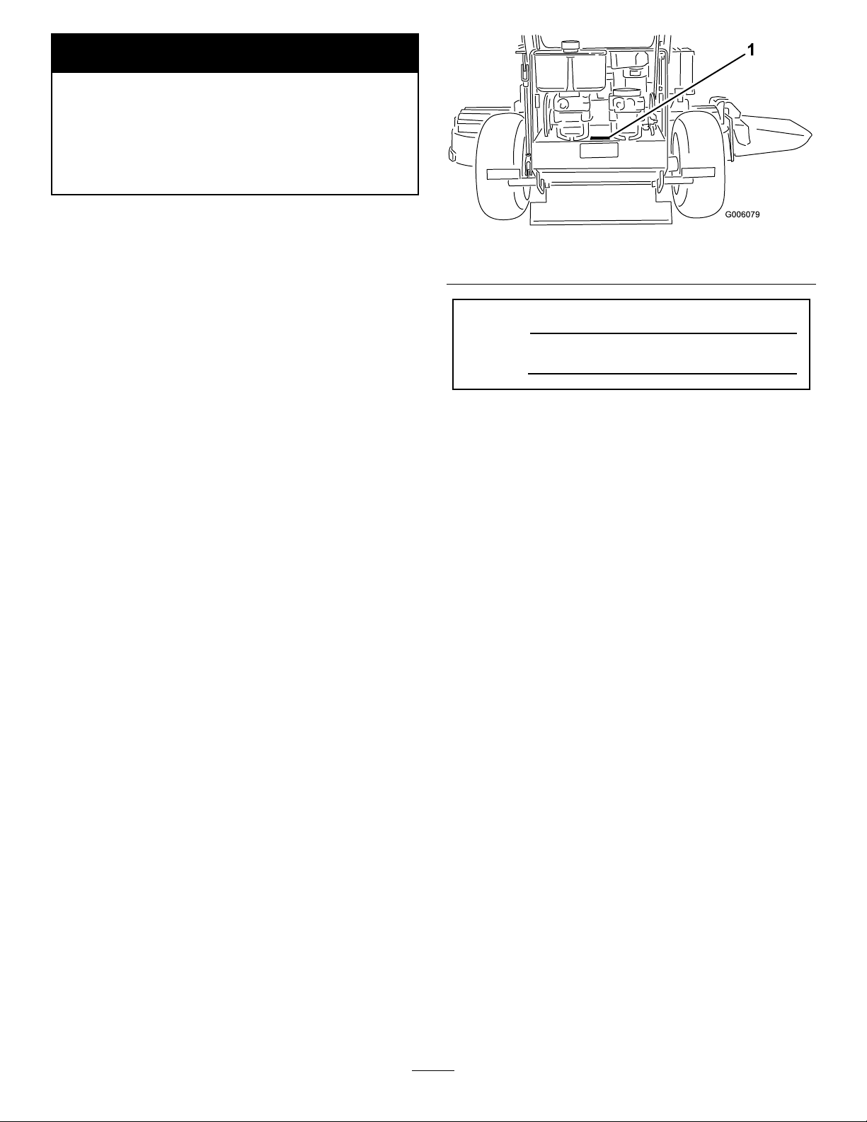
Figure1
1.Locationofthemodelandserialnumbers
ModelNo.
SerialNo.
Thismanualidentiespotentialhazardsandhassafety
messagesidentiedbythefollowingwords:
•Dangersignalsanextremehazardthatwillcause
seriousinjuryordeathifyoudonotfollowthe
recommendedprecautions.
•Warningsignalsahazardthatmaycauseserious
injuryordeathifyoudonotfollowtherecommended
precautions.
•Cautionsignalsahazardthatmaycauseminor
ormoderateinjuryifyoudonotfollowthe
recommendedprecautions.
Thismanualusestwootherwordstohighlight
information.Importantcallsattentiontospecial
mechanicalinformationandNoteemphasizesgeneral
informationworthyofspecialattention.
Wheneveryouneedservice,genuineToroparts,or
additionalinformation,contactanAuthorizedService
DealerorToroCustomerServiceandhavethemodel
andserialnumbersofyourproductready .Figure1
identiesthelocationofthemodelandserialnumbers
ontheproduct.Writethenumbersinthespace
provided.
©2008—TheToro®Company
8111LyndaleAvenueSouth
Bloomington,MN55420
Contents
Introduction.................................................................2
Safety...........................................................................4
SafeOperatingPractices.......................................4
ToroMowerSafety...............................................5
SlopeChart..........................................................7
SafetyandInstructionalDecals.............................8
ProductOverview......................................................11
Controls.............................................................11
Specications.....................................................12
Operation...................................................................13
AddingFuel.......................................................13
CheckingtheEngineOilLevel............................14
ThinkSafetyFirst...............................................14
OperatingtheParkingBrake...............................14
Contactusatwww.Toro.com.
2
PrintedintheUSA.
AllRightsReserved
Page 3

StartingandStoppingtheEngine........................14
OperatingtheMowerBladeControl
(PTO)............................................................15
TheSafetyInterlockSystem................................16
DrivingForwardorBackward.............................16
StoppingtheMachine.........................................17
PushingtheMachinebyHand.............................17
TransportingMachines.......................................18
SideDischargingorMulchingtheGrass..............18
AdjustingtheHeight-of-Cut...............................18
AdjustingtheAnti-ScalpRollers.........................19
AdjustingtheFlowBafe...................................20
PositioningtheFlowBafe.................................20
UsingtheMid-SizeWeight..................................22
Maintenance...............................................................23
RecommendedMaintenanceSchedule(s)................23
Lubrication.............................................................24
HowtoGrease...................................................24
LubricatingtheBearings.....................................24
GreasingthePTODriveBeltIdlerandMower
DeckBeltIdler...............................................24
EngineMaintenance...............................................25
ServicingtheAirCleaner....................................25
ServicingtheEngineOil.....................................26
ServicingtheSparkPlugs....................................27
FuelSystemMaintenance.......................................28
DrainingtheFuelTank.......................................28
ServicingtheFuelFilter......................................29
ElectricalSystemMaintenance................................30
ServicingtheBattery...........................................30
ServicingtheFuses.............................................32
DriveSystemMaintenance.....................................33
AdjustingtheTracking.......................................33
CheckingtheTirePressure.................................33
ReplacingtheCasterWheelFork
Bushings........................................................33
ServicingtheCasterWheelandBearings.............34
AdjustingtheElectricClutch..............................34
CoolingSystemMaintenance..................................35
CleaningtheAirIntakeScreen............................35
BrakeMaintenance.................................................36
ServicingtheBrake.............................................36
BeltMaintenance....................................................37
ReplacingtheMowerBelt...................................37
ReplacingthePTODriveBelt.............................37
AdjustingthePTODriveBeltIdlerSpring
Anchor...........................................................38
ReplacingthePumpDriveBelt...........................39
ControlsSystemMaintenance.................................40
AdjustingtheMotionControlHandle
Positions........................................................40
HydraulicSystemMaintenance...............................42
ServicingtheHydraulicSystem...........................42
MowerDeckMaintenance......................................44
ServicingtheCuttingBlades...............................44
CorrectingtheMowerQualityofCut..................47
FrameSetUp.....................................................47
CheckingtheMowerDeckFront-to-Rear
Pitch...............................................................49
ChangingtheMowerDeckFront-to-Rear
Pitch...............................................................49
CheckingtheMowerDeckSide-to-Side
Height............................................................50
ChangingtheMowerDeckSide-to-Side
Height............................................................50
MatchingHeightofCut......................................50
ReplacingtheGrassDeector.............................51
Cleaning.................................................................52
CleaningUndertheMower.................................52
WasteDisposal...................................................52
Storage.......................................................................52
CleaningandStorage..........................................52
Troubleshooting.........................................................54
Schematics.................................................................56
3
Page 4

Safety
Note:Theadditionofattachmentsmadeby
othermanufacturersthatdonotmeetAmerican
NationalStandardsInstitutecerticationwillcause
noncomplianceofthismachine.
Improperuseormaintenancebytheoperatororowner
canresultininjury.T oreducethepotentialforinjury,
complywiththesesafetyinstructionsandalwayspay
attentiontothesafetyalertsymbol
CAUTION,WARNING,orDANGER-“personalsafety
instruction."Failuretocomplywiththeinstructionmay
resultinpersonalinjuryordeath.
SafeOperatingPractices
ThefollowinginstructionsarefromANSIstandard
B71.4-2004.
Training
•ReadtheOperator’sManualandothertraining
material.Iftheoperator(s)ormechanic(s)cannot
readEnglishitistheowner’ sresponsibilitytoexplain
thismaterialtothem.
•Becomefamiliarwiththesafeoperationofthe
equipment,operatorcontrols,andsafetysigns.
•Alloperatorsandmechanicsshouldbetrained.The
ownerisresponsiblefortrainingtheusers.
•Neverletchildrenoruntrainedpeopleoperateor
servicetheequipment.Localregulationsmayrestrict
theageoftheoperator.
•Theowner/usercanpreventandisresponsiblefor
accidentsorinjuriesoccurringtohimselforherself,
otherpeopleorproperty.
Preparation
•Evaluatetheterraintodeterminewhataccessories
andattachmentsareneededtoproperlyand
safelyperformthejob.Onlyuseaccessoriesand
attachmentsapprovedbythemanufacturer.
•Wearappropriateclothingincludinghardhat,safety
glassesandhearingprotection.Longhair,loose
clothingorjewelrymaygettangledinmovingparts.
•Inspecttheareawheretheequipmentistobeused
andremoveallobjectssuchasrocks,toysandwire
whichcanbethrownbythemachine.
•Useextracarewhenhandlinggasolineandother
fuels.Theyareammableandvaporsareexplosive.
–Useonlyanapprovedcontainer
,whichmeans
–Neverremovegascaporaddfuelwithengine
running.Allowenginetocoolbeforerefueling.
Donotsmoke.
–Neverrefuelordrainthemachineindoors.
•Checkthatoperator’spresencecontrols,safety
switchesandshieldsareattachedandfunctioning
properly.Donotoperateunlesstheyarefunctioning
properly.
Operation
•Neverrunanengineinanenclosedarea.
•Onlyoperateingoodlight,keepingawayfromholes
andhiddenhazards.
•Besurealldrivesareinneutralandparkingbrakeis
engagedbeforestartingengine.Onlystartengine
fromtheoperator’sposition.
•Besureofyourfootingwhileusingthismachine,
especiallywhenbackingup.Walk,don’trun.Never
operateonwetgrass.Reducedfootingcouldcause
slipping.
•Slowdownanduseextracareonhillsides.Besure
totravelsidetosideonhillsides.Turfconditions
canaffectthemachine’ sstability.Usecautionwhile
operatingneardrop-offs.
•Slowdownandusecautionwhenmakingturnsand
whenchangingdirectionsonslopes.
•Neverraisedeckwiththebladesrunning.
•NeveroperatewiththePTOshield,orotherguards
notsecurelyinplace.Besureallinterlocksare
attached,adjustedproperly,andfunctioningproperly.
•Neveroperatewiththedischargedeectorraised,
removedoraltered,unlessusingagrasscatcher.
•Donotchangetheenginegovernorsettingor
overspeedtheengine.
•Stoponlevelground,disengagedrives,engage
parkingbrake(ifprovided),shutoffenginebefore
leavingtheoperator’spositionforanyreason
includingemptyingthecatchersoruncloggingthe
chute.
•Stopequipmentandinspectbladesafterstriking
objectsorifanabnormalvibrationoccurs.Make
necessaryrepairsbeforeresumingoperations.
•Keephandsandfeetawayfromthecuttingunit.
•Lookbehindanddownbeforebackinguptobesure
ofaclearpath.
•Keeppetsandbystandersaway.
•Slowdownandusecautionwhenmakingturnsand
crossingroadsandsidewalks.Stopbladesifnot
mowing.
4
Page 5

•Beawareofthemowerdischargedirectionanddo
notpointitatanyone.
•Donotoperatethemowerundertheinuenceof
alcoholordrugs.
Thisproductisdesignedforcuttingandrecyclinggrass
or,whenequippedwithagrassbagger,forcatching
cutgrass.Anyuseforpurposesotherthanthesecould
provedangeroustouserandbystanders.
•Usecarewhenloadingorunloadingthemachine
intoorfromatrailerortruck.
•Usecarewhenapproachingblindcorners,shrubs,
trees,orotherobjectsthatmayobscurevision.
Maintenanceandstorage
•Disengagedrives,setparkingbrake,stopengineand
removekeyordisconnectsparkplugwire.Waitfor
allmovementtostopbeforeadjusting,cleaningor
repairing.
•Cleangrassanddebrisfromcuttingunit,drives,
mufers,andenginetohelppreventres.Cleanup
oilorfuelspillage.
•Letenginecoolbeforestoringanddonotstorenear
ame.
•Shutofffuelwhilestoringortransporting.Donot
storefuelnearamesordrainindoors.
•Parkmachineonlevelground.Setparkingbrake.
Neverallowuntrainedpersonneltoservicemachine.
•Usejackstandstosupportcomponentswhen
required.
•Carefullyreleasepressurefromcomponentswith
storedenergy.
•Disconnectthebatteryorremovesparkplugwire
beforemakinganyrepairs.Disconnectthenegative
terminalrstandthepositivelast.Reconnectthe
positiverstandnegativelast.
•Usecarewhencheckingblades.Wraptheblade(s)or
weargloves,andusecautionwhenservicingthem.
Onlyreplaceblades.Neverstraightenorweldthem.
•Keephandsandfeetawayfrommovingparts.If
possible,donotmakeadjustmentswiththeengine
running.
•Keepallpartsingoodworkingconditionandall
hardwaretightened.Replaceallwornordamaged
decals.
GeneralOperation
•Besuretheareaisclearofotherpeoplebefore
mowing.Stopthemachineifanyoneentersthearea.
•Donottouchequipmentorattachmentpartswhich
maybehotfromoperation.Allowtocoolbefore
attemptingtomaintain,adjustorservice.
•UseonlyToroapprovedattachments.Warrantymay
bevoidedifusedwithunapprovedattachments.
•Checkcarefullyforoverheadclearances(i.e.
branches,doorways,electricalwires)before
operatingunderanyobjectsanddonotcontact
them.
SlopeOperation
Allslopesandrampsrequireextracaution.Ifyoufeel
uneasyonaslope,donotmowit.
•Removeobstaclessuchasrocks,treelimbs,etc.from
themowingarea.
•Watchforholes,rutsorbumps.Tallgrasscanhide
obstacles.
•Usecautionneardrop-offs,ditches,orembankments.
Themachinecouldsuddenlyturnoverifawheel
goesovertheedgeofaclifforditch,orifanedge
cavesin.
•Useextracarewithgrasscatchersorother
attachments.Thesecanchangethestabilityofthe
machine.
•Keepallmovementonslopesslowandgradual.Do
notmakesuddenchangesinspeedordirection.
•Mowslopessidetoside.
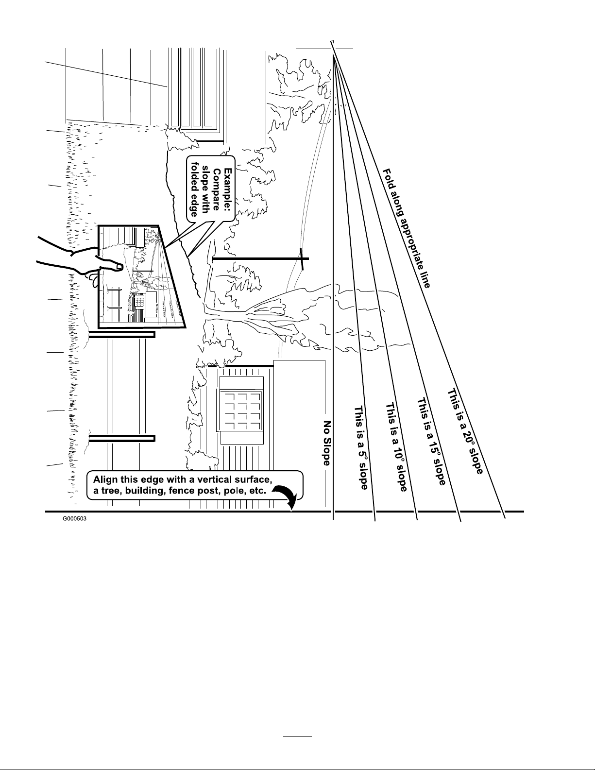
•Donotmowslopesgreaterthan20degrees.
Service
ToroMowerSafety
Thefollowinglistcontainssafetyinformationspecic
toToroproductsandothersafetyinformationyoumust
know .
Thisproductiscapableofamputatinghandsand
feetandthrowingobjects.Alwaysfollowallsafety
instructionstoavoidseriousinjuryordeath.
•Neverstorethemachineorfuelcontainerinside
wherethereisanopename,suchasnearawater
heaterorfurnace.
•Keepnutsandboltstight,especiallytheblade
attachmentbolts.Keepequipmentingood
condition.
•Nevertamperwithsafetydevices.Checksafety
systemsforproperoperationbeforeeachuse.
5
Page 6

•Useonlygenuinereplacementpartstoensurethat
originalstandardsaremaintained.
•Checkbrakeoperationfrequently.Adjustandservice
asrequired.
6
Page 7
SlopeChart7SafetyandInstructional
Decals
Page 8

Safetydecalsandinstructionsareeasilyvisibletotheoperatorandarelocatednearanyareaof
potentialdanger.Replaceanydecalthatisdamagedorlost.
98-0776
43-8480
98-5954
66-1340
BatterySymbols
Someorallofthesesymbolsareonyourbattery
1.Explosionhazard
2.Nore,opename,or
smoking.
3.Causticliquid/chemical
68-8340
burnhazard
4.Weareyeprotection9.Flusheyesimmediately
5.ReadtheOperator’s
Manual.
6.Keepbystandersasafe
distancefromthebattery.
7.Weareyeprotection;
explosivegasescan
causeblindnessandother
injuries
8.Batteryacidcancause
blindnessorsevereburns.
withwaterandgetmedical
helpfast.
10.Containslead;donot
discard.
95-2814
8
Page 9
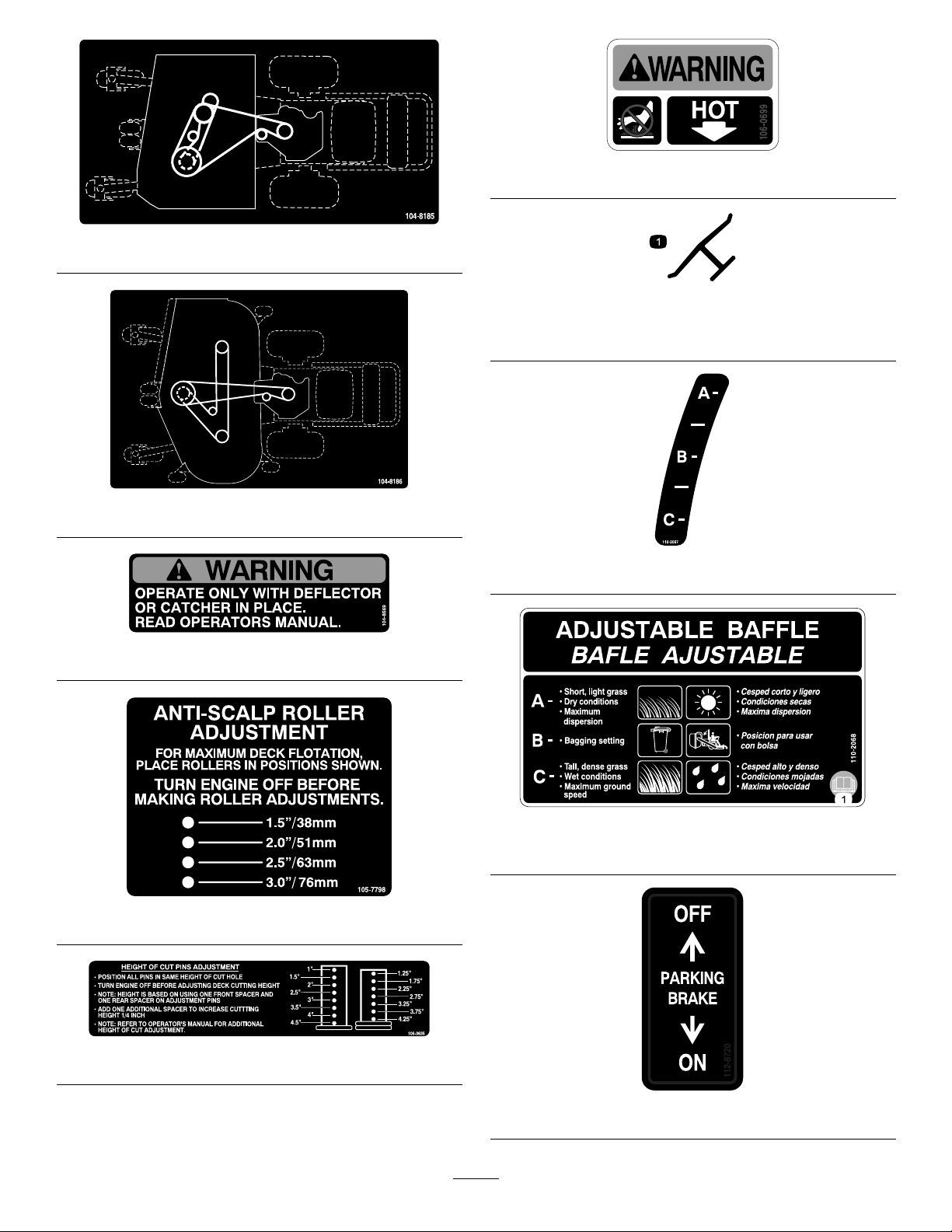
106-0699
104-8185
Manufacturer’sMark
1.Indicatesthebladeisidentiedasapartfromtheoriginal
machinemanufacturer.
104-8186
110-2067
104-8569
110-2068
1.ReadtheOperator’sManual.
105-7798
106-0635
112-8720
9
Page 10
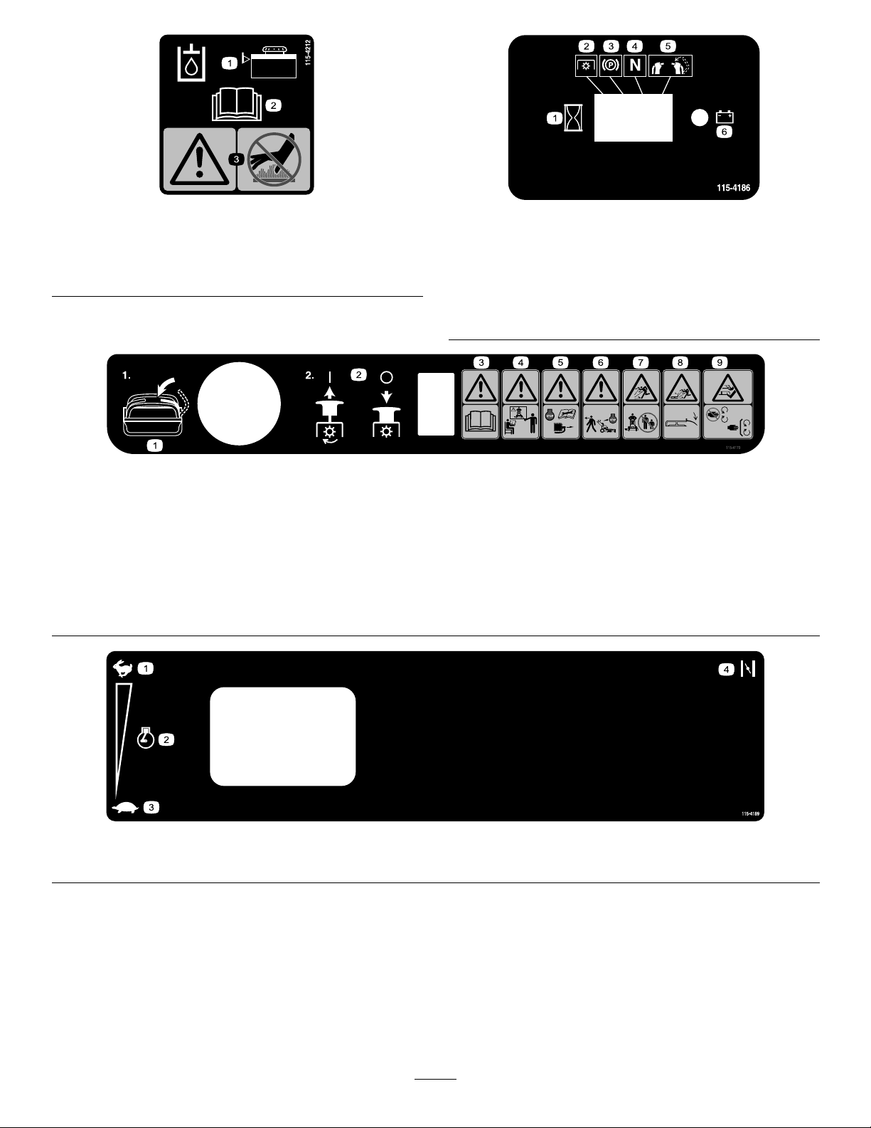
115-4212
1.Hydraulicoillevel3.Warning—donottouch
thehotsurface.
2.ReadtheOperator’s
Manual.
1.Interval
2.PowerT ake-off(PTO)
3.Parkingbrake
4.Neutral
5.Operatorpresenceswitch
6.Battery
115-4186
115–4179
1.Movethemotioncontrollevertotheneutralposition,thenpull
outonPTO(PowerT akeOff)switchtoengagetheblades.
2.PushinonthePTO(PowerT akeOff)todisengagetheblades.7.Thrownobjecthazard—keepbystandersasafedistancefrom
3.Warning—readtheOperator’sManual.8.Thrownobjecthazard—keepdeectorinplace.
4.Warning—donotoperatethismachineunlessyouaretrained.
5.Warning—stoptheengineandremovethesparkplugwire
beforeperforminganymaintenanceonthemachine.
6.Warning—stoptheenginebeforeleavingthemachine.
themachine.
9.Cutting,dismembermenthazardofhandorfoot—stayaway
frommovingparts;keepallguardsandshieldsinplace.
1.Fast2.Enginespeed
115–4189
3.Slow4.Choke
10
Page 11
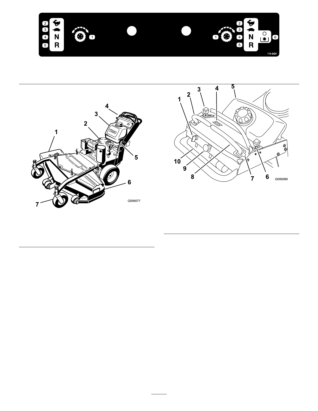
1.Tractioncontrol
2.Fast4.Neutral
ProductOverview
Figure2
1.Sidedischargechute
2.Engine6.Mowerdeck
3.Gastank
4.Controls
5.Parkingbrake
7.Frontcasterwheel
114-3424
3.Slow
1.Ignitionswitch
2.Leftmotioncontrollever7.Neutrallockpositionfor
3.Throttlecontrol8.Rightmotioncontrollever
4.Hourmeter
5.Fueltank
5.Reverse
6.DisengagethePTO(PowerT akeOff)
Figure3
6.Choke
rightmotioncontrollever
9.bladecontrolswitch(PTO)
10.Operatormanualtube
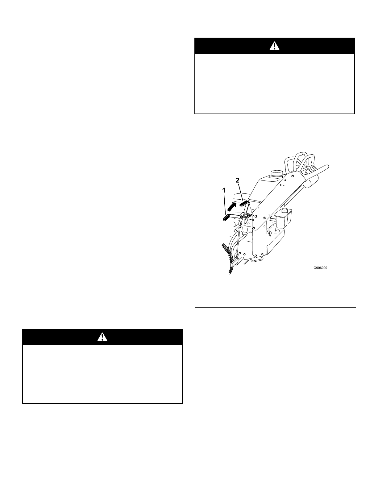
HourMeter
Controls
Becomefamiliarwithallthecontrols(Figure3)before
youstarttheengineandoperatethemachine.
Thehourmeterrecordsthenumberofhourstheengine
hasoperated.Itoperateswhentheengineisrunning.
Usethesetimesforschedulingregularmaintenance
(Figure4).
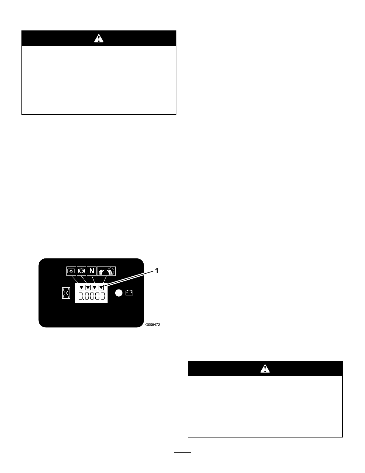
SafetyInterlockIndicators
Therearesymbolsonthehourmeterandindicatewith
ablacktrianglethattheinterlockcomponentisinthe
correctposition(Figure4).
BatteryIndicatorLight
WhentheignitionkeyisinitiallyturnedtotheOn
position,thebatteryvoltagewillbedisplayedinthearea
wherethehoursarenormallydisplayed.
Thebatterylightturnsonwhentheignitionisturned
onandwhenthechargeisbelowthecorrectoperating
level(Figure4).
11
Page 12
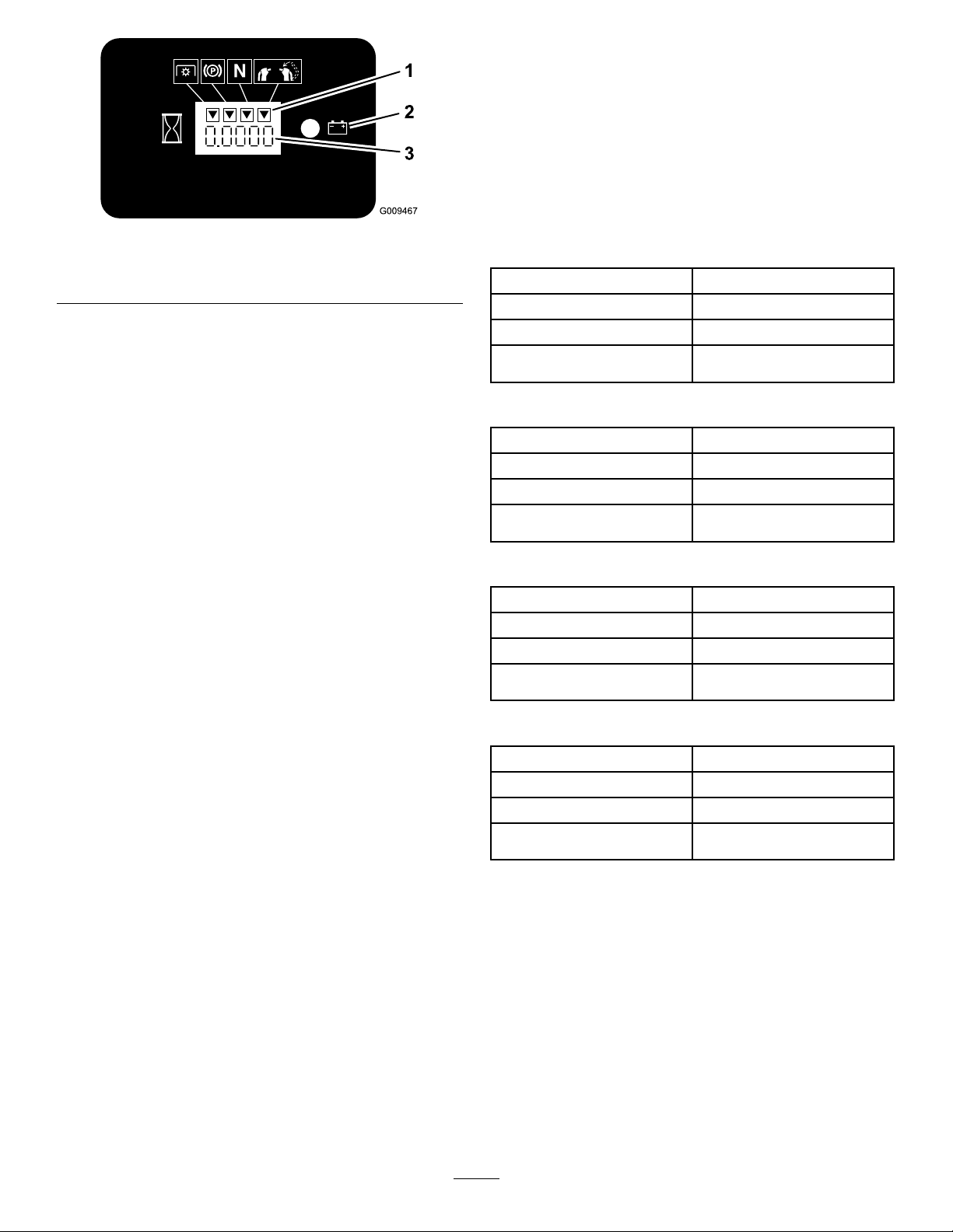
Figure4
1.Safetyinterlocksymbols
2.Batterylight
3.Hourmeter
ThrottleControl
Thethrottlecontrolhastwopositions:FastandSlow.
enhanceandexpanditscapabilities.Contactyour
AuthorizedServiceDealerorDistributororgoto
www.Toro.comforalistofallapprovedattachments
andaccessories.
Specications
Note:Specicationsanddesignaresubjecttochange
withoutnotice.
36inchmowers:
Widthwithdeectordown51–1/8inches(130cm)
Length
Height
Weight
78–1/2inches(199cm)
46inches(117cm)
667lb(303kg)
Choke
Usethechoketostartacoldengine.
BladeControlSwitch(PTO)
Thebladecontrolswitch(PTO)isusedtoengage
theelectricclutchtodrivethemowerbladeswiththe
rightsidemotioncontrolleverinthecenter,un-locked
position.Pulltheswitchuptoengagethebladesand
release.Todisengagetheblades,pushthebladecontrol
switch(PTO)downormoveorreleasetherightside
motioncontrolleverintotheneutrallockposition.
IgnitionSwitch
Thisswitchisusedtostartthemowerengineandhas
threepositions:Start,RunandOff.
MotionControlLevers
Themotioncontrolleversareusedtodrivethemachine
forward,reverse,andturneitherdirection.
40inchmowers:
Widthwithdeectordown55–1/2inches(141cm)
Length
Height
Weight
75–3/8inches(192cm)
46inches(117cm)
667lb(303kg)
48inchmowers:
Widthwithdeectordown63–1/2inches(161cm)
Length
Height
Weight
77–3/4inches(198cm)
46inches(117cm)
682lb(309kg)
52inchmowers:
Widthwithdeectordown67–5/8inches(171.7cm)
Length
Height
Weight
77–3/4inches(198cm)
46inches(117cm)
721lb(327kg)
NeutralLockPosition
Theneutrallockpositionisusedwiththesafetyinterlock
systemtoengageanddisengagethemowerbladesand
todetermineneutralposition.
FuelShut-offValve
Closethefuelshut-offvalve(underthefueltank)when
transportingorstoringthemower.
Attachments/Accessories
AselectionofToroapprovedattachmentsand
accessoriesareavailableforusewiththemachineto
12
Page 13

Operation
AddingFuel
UseUnleadedRegularGasolinesuitablefor
automotiveuse(85pumpoctaneminimum).Leaded
regulargasolinemaybeusedifunleadedregularisnot
available.
Important:Neverusemethanol,gasoline
containingmethanol,orgasoholcontainingmore
than10%ethanolbecausethefuelsystemcouldbe
damaged.Donotmixoilwithgasoline.
Incertainconditions,gasolineisextremely
ammableandhighlyexplosive.Areor
explosionfromgasolinecanburnyouand
othersandcandamageproperty.
•Fillthefueltankoutdoors,inanopenarea,
whentheengineiscold.Wipeupany
gasolinethatspills.
•Neverllthefueltankinsideanenclosed
trailer.
•Donotllthefueltankcompletelyfull.Add
gasolinetothefueltankuntilthelevelis1/4
to1/2inch(6to13mm)belowthebottomof
thellerneck.Thisemptyspaceinthetank
allowsgasolinetoexpand.
Incertainconditionsduringfueling,static
electricitycanbereleasedcausingaspark
whichcanignitethegasolinevapors.Are
orexplosionfromgasolinecanburnyouand
othersandcandamageproperty.
•Alwaysplacegasolinecontainersonthe
groundawayfromyourvehiclebeforelling.
•Donotllgasolinecontainersinsidea
vehicleoronatruckortrailerbedbecause
interiorcarpetsorplastictruckbedliners
mayinsulatethecontainerandslowtheloss
ofanystaticcharge.
•Whenpractical,removegas-powered
equipmentfromthetruckortrailerand
refueltheequipmentwithitswheelsonthe
ground.
•Ifthisisnotpossible,thenrefuelsuch
equipmentonatruckortrailerfroma
portablecontainer,ratherthanfroma
gasolinedispensernozzle.
•Ifagasolinedispensernozzlemustbeused,
keepthenozzleincontactwiththerimof
thefueltankorcontaineropeningatall
timesuntilfuelingiscomplete.
•Neversmokewhenhandlinggasoline,and
stayawayfromanopenameorwhere
gasolinefumesmaybeignitedbyaspark.
•Storegasolineinanapprovedcontainerand
keepitoutofthereachofchildren.Never
buymorethana30-daysupplyofgasoline.
•Donotoperatewithoutentireexhaust
systeminplaceandinproperworking
condition.
Gasolineisharmfulorfatalifswallowed.
Long-termexposuretovaporscancauseserious
injuryandillness.
•Avoidprolongedbreathingofvapors.
•Keepfaceawayfromnozzleandgastankor
conditioneropening.
•Keepgasawayfromeyesandskin.
UsingStabilizer/Conditioner
Useafuelstabilizer/conditionerinthemachineto
providethefollowingbenets:
•Keepsgasolinefreshduringstorageof90daysor
less.Forlongerstorageitisrecommendedthatthe
fueltankbedrained.
•Cleanstheenginewhileitruns
•Eliminatesgum-likevarnishbuildupinthefuel
system,whichcauseshardstarting
13
Page 14
Important:Donotusefueladditives
containingmethanolorethanol.
Addthecorrectamountofgas
stabilizer/conditionertothegas.
Iftheparkingbrakedoesnotholdsecurely,adjustit.
RefertoServicingtheParkingBrake.
Note:Afuelstabilizer/conditionerismost
effectivewhenmixedwithfreshgasoline.To
minimizethechanceofvarnishdepositsinthefuel
system,usefuelstabilizeratalltimes.
FillingtheFuelTank
1.Shuttheengineoffandsettheparkingbrake.
2.Cleanaroundfueltankcapandremovethecap.
Addunleadedregulargasolinetofueltank,untilthe
levelis1/4to1/2inch(6to13mm)belowthe
bottomofthellerneck.Thisspaceinthetank
allowsgasolinetoexpand.Donotllthefueltank
completelyfull.
3.Installfueltankcapsecurely.Wipeupanygasoline
thatmayhavespilled.
CheckingtheEngineOilLevel
Beforeyoustarttheengineandusethemachine,check
theoillevelintheenginecrankcase;refertoChecking
OilLevelinEngineMaintenance.
Childrenorbystandersmaybeinjuredifthey
moveorattempttooperatethemachinewhile
itisunattended.
Alwaysremovetheignitionkeyandsetthe
parkingbrakewhenleavingthemachine
unattended,evenifjustforafewminutes.
SettingtheParkingBrake
Pulltheparkingbrakeleverrearward(Figure5).
Note:Determinetheleftandrightsidesofthe
machinefromthenormaloperatingposition.
ThinkSafetyFirst
Carefullyreadallthesafetyinstructionsanddecalsin
thesafetysection.Knowingthisinformationcould
helpyouoranybystandersavoidinjury.
Theuseofprotectiveequipmentforeyes,hearing,feet
andheadisrecommended.
Thismachineproducessoundlevelsinexcess
of85dBAattheoperator’searandcancause
hearinglossthroughextendedperiodsof
exposure.
Wearhearingprotectionwhenoperatingthis
machine.
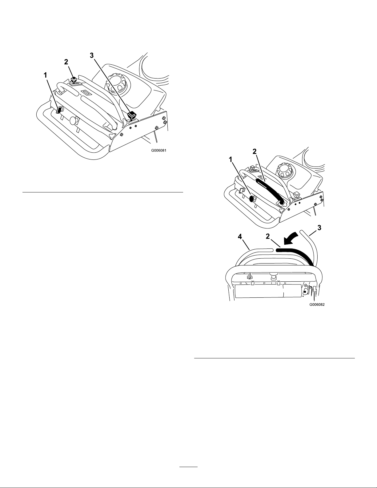
OperatingtheParkingBrake
Figure5
1.Parkingbrakelever(inthe
releasedposition)
2.Parkingbrakelever(inthe
engagedposition)
ReleasingtheParkingBrake
Pushtheparkingbrakeleverforward.
StartingandStoppingthe
Engine
StartingtheEngine
1.Connectthewirestothesparkplugs.
2.Openthefuelvalve.
3.Settheparkingbrake.
Alwayssettheparkingbrakewhenyoustopthe
machineorleaveitunattended.Beforeeachuse,check
theparkingbrakeforproperoperation.
4.Movethethrottlecontroltofastandmovethe
chokelevertotheonpositionbeforestartingacold
engine(Figure6).
14
Page 15
Note:Awarmorhotenginemaynotrequire
choking.Tostartawarmengine,movethrottle
controlmidwaybetweenthefastandslow
positions.
Figure6
1.Ignitionswitch
2.Throttlelever
3.Choke
OperatingtheMowerBlade
Control(PTO)
Thebladecontrolswitch(PTO)isusedinconjunction
withtherightsidemotioncontrollevertoengageand
disengagethemowerblades.
EngagingtheMowerBlades(PTO)
1.Toengagethemowerblades,movetherightside
motioncontrollevertothecenter,un-locked
position(Figure7).
2.Pullthebladecontrolswitch(PTO)upandrelease
itwhileholdingdowntherightsidemotioncontrol
leverinthecenter,un-lockedposition.
5.Turntheignitionkeytothestartpositionto
energizethestarter.Whentheenginestarts,release
thekey .
Note:Donotengagethestarterformorethan
5secondsatatime.Iftheenginefailstostart,
allowfora15secondcool-downperiodbetween
attempts.Failuretofollowtheseinstructionscan
burnoutthestartermotor.
6.Whenenginestarts,movethethrottlecontrol
betweenthefastandslowpositionandmovethe
chokelevertotheoffposition.Allowtheengine
towarmupandthenmovethethrottlecontrolto
thefastposition.
StoppingtheEngine
1.Movethemotioncontrolleverstoneutralandmove
therightsidemotioncontrolleverintotheneutral
lockposition.
2.Movethethrottlelevertoslow(Figure6).
3.Iftheenginehasbeenworkinghardorishot,let
theengineidlefor30to60secondsbeforeturning
theengineoff.
4.Tostoptheengine,turntheignitionkeytooff.
Important:Makesurefuelshutoffvalve
isclosedbeforetransportingorstoringthe
machine,asfuelleakagemayoccur.Before
storingthemachine,pullwireoffsparkplug(s)
topreventpossibilityofaccidentalstarting.
Figure7
1.Bladecontrolswitch(PTO)
2.Rightsidemotioncontrol
leverpusheddownintothe
center,un-lockedposition
3.Rightmotioncontrollever
inneutrallockposition
4.Leftmotioncontrollever
DisengagingtheMowerBlades(PTO)
Thefollowingaretwooptionsfordisengagingthe
mowerblades.
•Pushthebladecontrolswitch(PTO)downtothe
offposition.
•Movethemotioncontrolleverstoneutralandmove
therightsidemotioncontrolleverintotheneutral
lockposition.
15
Page 16
TheSafetyInterlockSystem
1.Starttheengine;refertoStartingandStoppingthe
Enginein,page.
2.Settheparkingbrake.
Ifsafetyinterlockswitchesaredisconnected
ordamagedthemachinecouldoperate
unexpectedlycausingpersonalinjury.
•Donottamperwiththeinterlockswitches.
•Checktheoperationoftheinterlock
switchesdailyandreplaceanydamaged
switchesbeforeoperatingthemachine.
UnderstandingtheSafetyInterlock
System
Thesafetyinterlocksystemisdesignedtopreventthe
mowerbladesfromrotatingunless:
•Therightsidemotioncontrolleverismovedtothe
center,un-lockedposition.
•Thebladecontrolswitch(PTO)ispulledon.
Thesafetyinterlocksystemisdesignedtostopthe
mowerbladesifyoumoveorreleasetherightside
motioncontrolleverintotheneutrallockposition.
Thehourmeterhassymbolstonotifytheuserwhen
theinterlockcomponentisinthecorrectposition.
Whenthecomponentisinthecorrectposition,a
trianglewilllightupinthecorrespondingsquare.
3.Movetherightsidemotioncontrollevertothe
center,un-lockedposition.Thebladesshould
notrotate.
4.Movethemotioncontrolleversforward.The
engineshouldkill.
5.Starttheengineandreleasetheparkingbrake.
6.Movetherightsidemotioncontrollevertothe
center,un-lockedposition.
7.Continueholdingtherightsidemotioncontrollever
inthecenter,un-lockedpositionandpulluponthe
bladecontrolswitch(PTO)andrelease.Theclutch
shouldengageandthemowerbladesbeginrotating.
8.Moveorreleasetherightsidemotioncontrollever
intotheneutrallockposition.Thebladesshould
stoprotating.
9.Movetherightsidemotioncontrollevertothe
center,un-lockedposition.
10.Continueholdingtherightsidemotioncontrollever
inthecenter,un-lockedpositionandpulluponthe
bladecontrolswitch(PTO)andrelease.Theclutch
shouldengageandthemowerbladesbeginrotating.
11.Pushthebladecontrolswitch(PTO)downtothe
offposition.Thebladesshouldstoprotating.
Figure8
1.Triangleslightupwhentheinterlockcomponentsareinthe
correctposition
TestingtheSafetyInterlockSystem
ServiceInterval:Beforeeachuseordaily
Testthesafetyinterlocksystembeforeyouusethe
machineeachtime.
Note:Ifthesafetysystemdoesnotoperateas
describedbelow,haveanAuthorizedServiceDealer
repairthesafetysystemimmediately.
12.Withtheenginerunning,pullupthebladecontrol
switch(PTO)andreleasewithoutholdingright
sidemotioncontrollevertothecenter,un-locked
position.Thebladesshouldnotrotate.
DrivingForwardorBackward
Thethrottlecontrolregulatestheenginespeedas
measuredinrpm(revolutionsperminute).Place
thethrottlecontrolinthefastpositionforbest
performance.Alwaysoperateinthefullthrottle
positionwhenmowing.
Machinecanspinveryrapidly .Operatormay
losecontrolofmachineandcausepersonal
injuryordamagetomachine.
•Usecautionwhenmakingturns.
•Slowthemachinedownbeforemaking
sharpturns.
16
Page 17
DrivingForward
1.Releasetheparkingbrake;refertoReleasingthe
ParkingBrakein,page.
2.Movetherightsidemotioncontrollevertothe
center,un-lockedposition.
StoppingtheMachine
Tostopthemachine,movethemotioncontrolleversto
neutral,movetherightsidemotioncontrolleverinto
theneutrallockposition,disengagethepowertakeoff
(PTO),andturntheignitionkeytooff.
3.Togoforward,slowlypushthemotioncontrol
leversforward(Figure9).
Note:Theenginewillkillifthetractioncontrol
leversaremovedwiththeparkingbrakeengaged.
Togostraight,applyequalpressuretobothmotion
controllevers(Figure9).
Toturn,movethemotioncontrollevertoward
neutralinthedirectionyouwanttoturn(Figure9).
Thefartheryoumovethetractioncontrolleversin
eitherdirection,thefasterthemachinewillmovein
thatdirection.
Tostop,pullthemotioncontrolleversbacktothe
neutralposition.
Settheparkingbrakewhenyouleavethemachine;refer
toSettingtheParkingBrakein,page.Rememberto
removethekeyfromtheignitionswitch.
Childrenorbystandersmaybeinjuredifthey
moveorattempttooperatethetractorwhileit
isunattended.
Alwaysremovetheignitionkeyandsetthe
parkingbrakewhenleavingthemachine
unattended,evenifjustforafewminutes.
PushingtheMachinebyHand
Theby-passvalvesallowthemachinetobepushedby
handwithouttheenginerunning.
Important:Alwayspushthemachinebyhand.
Nevertowthemachinebecausehydraulicdamage
mayoccur.
Figure9
1.Forward2.Backward
DrivingBackward
1.Movetherightsidemotioncontrollevertothe
center,un-lockedposition.
2.Togobackward,slowlypullthemotioncontrol
leversrearward(Figure9).
Togostraight,applyequalpressuretobothmotion
controllevers(Figure9).
Toturn,releasepressureonthemotioncontrollever
towardthedirectionyouwanttoturn(Figure9).
Tostop,pushthemotioncontrolleverstothe
neutralposition.
ToPushtheMachine
1.DisengagethePTO,movethemotioncontrol
leverstotheneutrallockedpositionandsetthe
parkingbrake.
2.Opentheby-passvalveonbothpumpsbyturning
themcounterclockwise1to2turns.Thisallows
hydraulicuidtoby-passthepumpsandthewheels
toturn(Figure10).
Note:Rotatetheby-passvalvesamaximumof2
turnssothevalvedoesnotcomeoutofthebody
causinguidtorunout.
17
Page 18
1.Pumpby-passvalve
Figure11
1.Tractionunittiedownloop
Figure10
SideDischargingorMulching
3.Releasetheparkingbrake.
4.Pushthemachinetothedesiredlocation.
5.Settheparkingbrake.
6.Closetheby-passvalves,butdonotovertighten
them.
Important:Donotstartoroperatethe
machinewiththeby-passvalvesopen.Damage
tosystemmayoccur.
TransportingMachines
Useaheavy-dutytrailerortrucktotransportthe
machine.Ensurethatthetrailerortruckhasall
necessarybrakes,lighting,andmarkingasrequiredby
law .Pleasecarefullyreadallthesafetyinstructions.
Knowingthisinformationcouldhelpyou,yourfamily ,
petsorbystandersavoidinjury.
Totransportthemachine:
1.Ifusingatrailer,connectittothetowingvehicle
andconnectthesafetychains.
2.Ifapplicable,connectthetrailerbrakes.
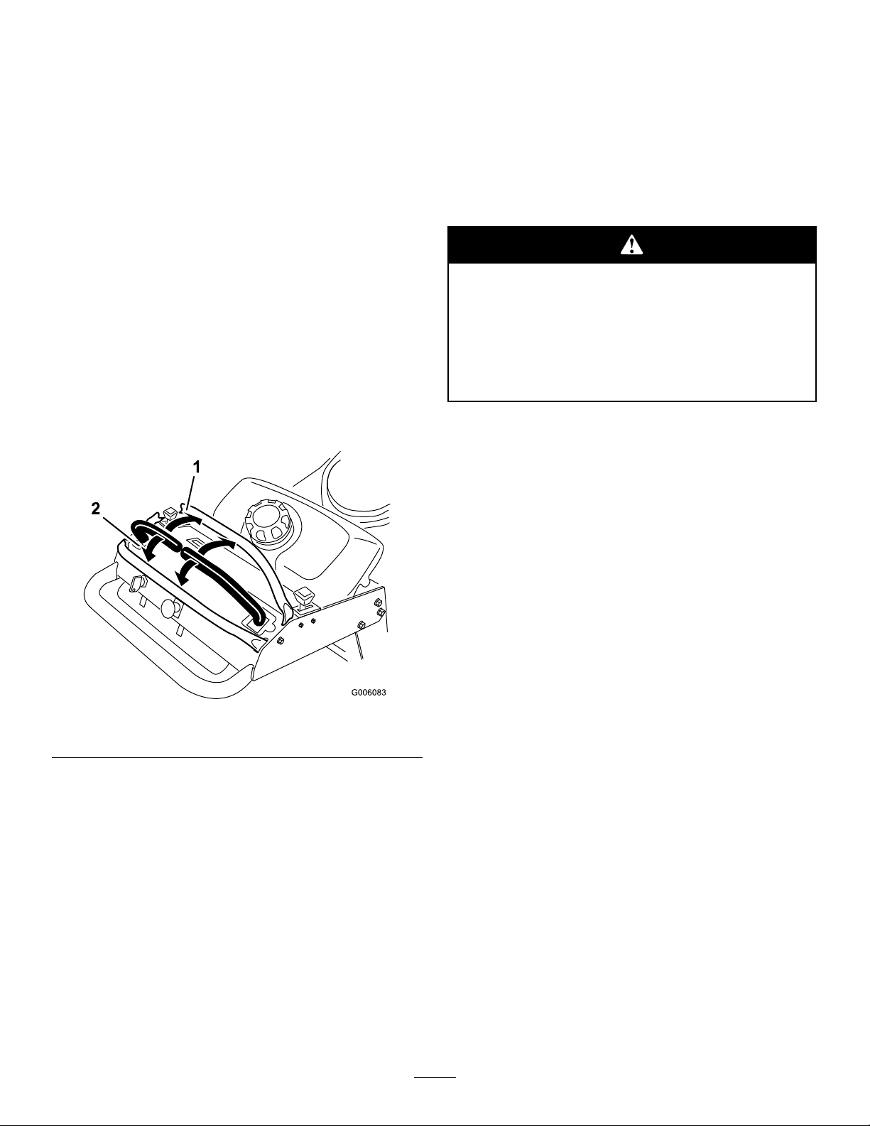
3.Loadthemachineontothetrailerortruck.
theGrass
Thismowerhasahingedgrassdeectorthatdisperses
clippingstothesideanddowntowardtheturf.
Withoutthegrassdeector,dischargecover,
orcompletegrasscatcherassemblymounted
inplace,youandothersareexposedtoblade
contactandthrowndebris.Contactwith
rotatingmowerblade(s)andthrowndebriswill
causeinjuryordeath.
•Neverremovethegrassdeectorfrom
themowerbecausethegrassdeector
routesmaterialdowntowardtheturf.Ifthe
grassdeectoriseverdamaged,replaceit
immediately.
•Neverputyourhandsorfeetunderthe
mower.
•Nevertrytocleardischargeareaormower
bladesunlessyoureleasethebailandthe
powertakeoff(PTO)isoff.Rotatethe
ignitionkeytoOff.Alsoremovethekeyand
pullthewire(s)offthesparkplug(s).
4.Stoptheengine,removethekey,setthebrake,and
closethefuelvalve.
5.Usethemetaltiedownloopsonthemachineto
securelyfastenthemachinetothetrailerortruck
withstraps,chains,cable,orropes(Figure11).
6.Fastenthefrontofthemachinetothetraileror
truckwithstraps,chains,cable,orropes.
AdjustingtheHeight-of-Cut
Theheight-of-cutcanbeadjustedfrom1to4-1/2
inch(25to114mm)in1/4inch(6mm)increments.
Adjustmentisdonebyrelocatingfourhairpincotter
pinsindifferentholelocationandbyaddingor
removingspacers.
Note:Allheight-of-cutpinsneedatleastonespacer
ordamagecanoccurtobushingifnoneareused.
18
Page 19

Note:Allheight-of-cutpinscanusetwospacers
maximum.
1.Selectholeinheight-of-cutpostandnumberof
spacerscorrespondingtotheheight-of-cutdesired
(Figure12).
2.Usingthelifthandle,raisesideofdeckandremove
hairpincotter(Figure12).
3.Addorremovespacersifneededandthenalign
holesandinserthairpincotter(Figure12).
Note:Spareheight-of-cutspacersmaybestored
onpostsandretainedbyahairpincotter.
Important:Allfourhairpincotterpinsmustbe
inthesameholelocationandwiththecorrect
numberofspacersforalevelcut.
1.Afteradjustingheight-of-cut,checktheanti-scalp
rollerssothatthereisaminimumof3/8inch
(10mm)clearanceabovetheground(Figure13,
Figure14,Figure15).
2.Ifadjustmentisneeded,removethebolt,washers
andnut(Figure13,Figure14,Figure15).
3.Selectaholepositionsotheanti-scalprollersare
aminimumof3/8inch(10mm)offtheground
(Figure13,Figure14,Figure15).
4.Installtheboltandnut(Figure13,Figure14,
Figure15).
Figure12
1.CarrierFrame4.Spacers
2.HairpinCotter5.Frontheight-of-cutpost
3.Backheight-of-cutpost
AdjustingtheAnti-Scalp
Rollers
Theanti-scalprollersneedtobeadjustedintheproper
holelocationforeachheight-of-cutposition.There
needstobe3/8inch(10mm)minimumclearance
abovetheground.
Figure13
40inch,48inch,and52inchMowerDecks
1.Mowerdeck
2.Bolt5.Nut
3.Spacer
4.Anti-ScalpRollers
Note:Iftheanti-scalprollersareadjustedtoolowit
cancauseexcesswearoftherollers.
19
Page 20

Figure14
40inch,48inch,and52inchMowerDecks
1.Mowerdeck4.Bushing
2.Bolt
3.Spacer
1.DisengagethePTO,movethemotioncontrol
leverstotheneutrallockedpositionandsetthe
parkingbrake.
2.Stoptheengine,removethekey ,andwaitforall
movingpartstostopbeforeleavingtheoperating
position.
3.Toadjustthecamlock,swingtheleveruptoloosen
thecamlock(Figure16).
4.Adjustthebafeandcamlockintheslottothe
desireddischargeow .
5.Swingtheleverbackovertotightenthebafeand
camlock(Figure16).
6.Ifthecamdoesnotlockthebafeintoplaceoritis
tootight,loosentheleverandthenrotatethecam
lock.Adjustthecamlockuntilthedesiredlocking
pressureisachieved.
5.Anti-ScalpRollers
6.Nut
Figure15
36inchMowerDeck
1.Mowerdeck
2.Bolt5.Nut
3.Spacer
4.Anti-ScalpRollers
5.Incertainmowingconditionsandterrain,a
mismatchofcuttingheightmaybeseen.Adjusting
theoutsideanti-scalprollerstotheminimumsetting
of3/8inch(10mm)willhelppreventthemower
deckcuttingtoolowontheoutsideandminimize
themismatch.
AdjustingtheFlowBafe
Themowerdischargeowcanbeadjustedfordifferent
typesofmowingconditions.Positionthecamlockand
bafetogivethebestqualityofcut.
Figure16
1.Camlock
2.Lever
3.Rotatecamtoincreaseor
decreaselockingpressure
4.Slot
PositioningtheFlowBafe
Thefollowingguresareonlyrecommendationsfor
use.Adjustmentswillvarybygrasstype,moisture
content,andheightofgrass.
Note:Iftheenginepowerdrawsdownandthemower
groundspeedisthesame,openupthebafe.
PositionA
Thisisthefullrearposition(seeFigure17).The
suggesteduseforthispositionisafollows.
•Useforshort,lightgrassmowingconditions.
•Useindryconditions.
•Forsmallergrassclippings.
•Propelsgrassclippingsfartherawayfromthe
mower.
20
Page 21

Figure17
PositionB
Usethispositionwhenbagging(Figure18).
Figure19
Figure18
PositionC
Thisisthefullopenposition.Thesuggestedusefor
thispositionisasfollows(Figure19).
•Useintall,densegrassmowingconditions.
•Useinwetconditions.
•Lowerstheenginepowerconsumption.
•Allowsincreasedgroundspeedinheavyconditions.
•ThispositionissimilartothebenetsoftheToro
SFSmower.
21
Page 22

UsingtheMid-SizeWeight
Weightsareinstalledoncertainmowerstoimprove
balanceandimproveperformance.Theweightscanbe
movedorremovedtocreateoptimizedperformance
underdifferentmowingconditionsandforoperator
preference(Figure20orFigure21).
Thefollowingtableindicatesthepositionoftheweight
asinstalledatthefactory.
MowerDeckSizeNumberofweights
36inches1Front
40inches1Front
48inches
52inches1Rear
install
nonenone
Positionofthe
•Anyrearweightmustberemovedwhena
Tru–Track
•WhenaTru–Track
®
Sulkyisinstalled.
®
Sulkyisinstalledfrontweights
areneeded.ContactanAuthorizedServiceDealer
forthecorrectquantityofweightsandplacement.
Thefrontendofthemachinecanrapidlyrise
upwhenthemowerisremoved.Thiscould
causeseriousinjurytoyouorbystanders.
Supporttherearofthemachinewhenremoving
themowerfromthecarrierframe.
weight
Figure20
Installingthefrontweight.
1.Bolt3.Weight
2.Washer4.Nut
Figure21
Installingtherearweight.
1.Nut3.Washer
2.Weight4.Bolt
22
Page 23

Maintenance
Note:Determinetheleftandrightsidesofthemachinefromthenormaloperatingposition.
RecommendedMaintenanceSchedule(s)
MaintenanceService
Interval
Aftertherst8hours
Beforeeachuseordaily
Every25hours
Every50hours
Every100hours
MaintenanceProcedure
•Changetheengineoil.
•Checkthehydraulicuidlevel.
•Changethehydrauliclter.
•Checkthesafetyinterlocksystem.
•Greasethefrontcasterpivotbearing.
•Checktheengineoillevel.
•Cleantheairintakescreen.
•Checkthebrakes.
•Inspecttheblades.
•Cleanthemowerdeck.
•Cleanfoamaircleanerelement.
•Checkthebatteryelectrolytelevel.
•Checkthehydraulicuidlevel.
•Greasethesidebearings.
•GreasethePTObeltidler.
•Greasethemowerdeckbeltidler.
•Checkthepaperaircleanerelement.
•Checkthetirepressure.
•Checkthemowerbelt.
•CheckthePTOdrivebelt.
•Checkthepumpdrivebelt.
•Checkthesparkplugs.
•Adjusttheelectricclutch.
•Checkthehydrauliclines.
•Replacethepaperaircleanerelement.
Every200hours
Every400hours
Beforestorage
Important:Refertoyour
•Changetheoillter.
•Replacethefuellter.
•Changethehydrauliclter.
•Greasethefrontwheelbearings(moreoftenindirtyordustyconditions).
•Paintchippedsurfaces.
•Performallmaintenanceprocedureslistedabovebeforestorage.
Engine Operator’ s Man ual
foradditionalmaintenanceprocedures.
Ifyouleavethekeyintheignitionswitch,someonecouldaccidentlystarttheengineandseriously
injureyouorotherbystanders.
Removethekeyfromtheignitionanddisconnectthesparkplugwiresfromthesparkplugsbeforeyou
doanymaintenance.Setthewiresasidesothattheydonotaccidentallycontactthesparkplugs.
23
Page 24

Lubrication
GreasingthePTODriveBelt
GreasewithNo.2generalpurposelithiumbaseor
molybdenumbasegrease.
HowtoGrease
1.DisengagethePTOandsettheparkingbrake.
2.Stoptheengine,removethekey,andwaitforall
movingpartstostopbeforeleavingtheoperating
position.
3.Cleanthegreasettingswitharag.Makesureto
scrapeanypaintoffthefrontofthetting(s).
4.Connectagreaseguntothetting.Pumpgrease
intothettingsuntilgreasebeginstooozeoutof
thebearings.
5.Wipeupanyexcessgrease.
LubricatingtheBearings
ServiceInterval:Beforeeachuseordaily
IdlerandMowerDeckBelt
Idler
ServiceInterval:Every50hours
Every50hours
Greasetheidlerpulleypivots(Figure23orFigure24).
Note:Youwillhavetoremovethecarriercoversto
accessthegreasettingforthemowerdeck.
Every400hours
Every50hours
Lubricatethefrontcasterwheelbearingsandfront
pivots(Figure22).
Note:Makesuretherearwheelgreasecapsare
removedbeforelubricatingrearwheels.
Figure23
40inch,48inch,and52inchMowerDeckshown
Figure22
Figure24
36inchMowerDeckshown
24
Page 25

EngineMaintenance
ServicingtheAirCleaner
ServiceInterval/Specication
Foamelement:Cleanitafterevery25operatinghours.
Paperelement:Checkitafterevery50operatinghours.
Replaceitafterevery200operatinghoursoryearly,
whichevercomesrst.
Inspectthefoamandpaperelementsandreplacethem
iftheyaredamagedorexcessivelydirty.
Note:Servicetheaircleanermorefrequently(every
fewoperatinghours)iftheoperatingconditionsare
extremelydustyorsandy .
Important:Donotoilthefoamorpaperelement.
RemovingtheFoamandPaper
Elements
1.DisengagethePTOandsettheparkingbrake.
2.Stoptheengine,removethekey,andwaitforall
movingpartstostopbeforeleavingtheoperating
position.
Figure25
1.Engine4.Foamelement
2.Cover
3.Wingnut
5.Paperelement
6.Coverknob
3.Cleanaroundtheaircleanertopreventdirt
fromgettingintotheengineandcausingdamage
(Figure25).
4.Unscrewthecoverknobandremovetheaircleaner
cover(Figure25).
5.Removethe2wingnutsandremovetheaircleaner
assembly(Figure25).
6.Carefullypullthefoamelementoffthepaper
element(Figure25).
CleaningtheFoamAirCleanerElement
ServiceInterval:Every25hours
1.Washthefoamelementinliquidsoapandwarm
water.Whentheelementisclean,rinseitthoroughly.
2.Drytheelementbysqueezingitinacleancloth.
Important:Replacethefoamelementifitis
tornorworn.
ServicingthePaperAirCleaner
Element
ServiceInterval:Every50hours
Every200hours
1.Donotcleanthepaperlter.Replaceitafter200
operatinghours(Figure25).
2.Inspecttheelementfortears,anoilylm,ordamage
totherubberseal.
3.Replacethepaperelementifitisdamaged.
25
Page 26
InstallingtheFoamandPaperElements
Important:Topreventenginedamage,always
operatetheenginewiththecompletefoamand
paperaircleanerassemblyinstalled.
1.Carefullyslidethefoamelementontothepaperair
cleanerelement(Figure25).
2.Placetheaircleanerassemblyontotheaircleaner
baseandsecureitwiththe2wingnuts(Figure25).
3.Placetheaircleanercoverintopositionandtighten
thecoverknob(Figure25).
ServicingtheEngineOil
3.Stoptheengine,removethekey,andwaitforall
movingpartstostopbeforeleavingtheoperating
position.
4.Cleanaroundtheoildipstick(Figure27)sothatdirt
cannotfallintothellerholeanddamagetheengine.
ServiceInterval/Specication
Checktheengineoilleveldaily.
Changetheengineoilasfollows:
•Aftertherst8operatinghours
•Afterevery100operatinghours
Note:Changetheoilmorefrequentlywhenthe
operatingconditionsareextremelydustyorsandy.
OilType:Detergentoil(APIserviceSF ,SG,SH,
orSJ)
CrankcaseCapacity:58ounces(1.7liter)withthe
lterremoved;51ounces(1.5liter)withoutthelter
removed
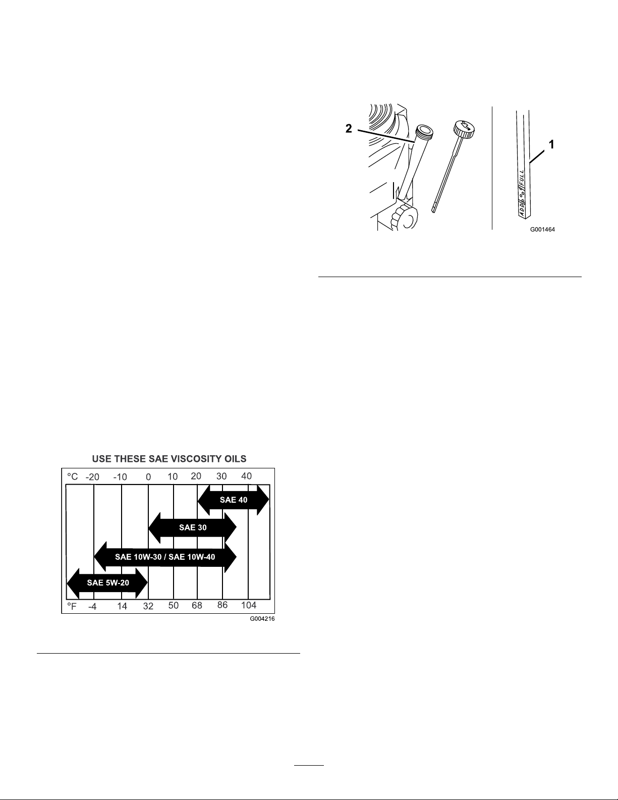
Viscosity:Refertothetable(Figure26).
Figure27
1.Oildipstick
5.Unscrewtheoildipstickandwipetheendclean
(Figure27).
6.Slidetheoildipstickfullyintothellertube,butdo
notthreadontotube(Figure27).
7.Pullthedipstickoutandlookattheend.Iftheoil
levelislow,slowlypouronlyenoughoilintotheller
tubetoraisetheleveltotheFullmark.
Important:Donotoverllthecrankcasewith
oilandruntheengine;enginedamagecan
result.
2.Fillertube
ChangingtheOil
ServiceInterval:Aftertherst8hours
1.Starttheengineandletitrunveminutes.This
warmstheoilsoitdrainsbetter.
2.Parkthemachinesothatthedrainsideisslightly
lowerthantheoppositesidetoassuretheoildrains
completely.
Figure26
CheckingtheEngineOilLevel
ServiceInterval:Beforeeachuseordaily
1.Parkthemachineonalevelsurface.
2.DisengagethePTOandsettheparkingbrake.
3.DisengagethePTOandsettheparkingbrake.
4.Stoptheengine,removethekey,andwaitforall
movingpartstostopbeforeleavingtheoperating
position.
5.Slidethedrainhoseovertheoildrainvalve.
6.Placeapanbelowthedrainhose.Rotateoildrain
valvetoallowoiltodrain(Figure28).
7.Whenoilhasdrainedcompletely,closethedrain
valve.
8.Removethedrainhose(Figure28).
Note:Disposeoftheusedoilatarecyclingcenter.
26
Page 27

Figure28
1
1.Oildrainvalve2.Oildrainhose
9.Slowlypourapproximately80%ofthespeciedoil
intothellertube(Figure27).
10.Checktheoillevel;refertoCheckingtheEngineOil
Level.
11.SlowlyaddtheadditionaloiltobringittotheFull
mark.
3.Applyathincoatofnewoiltotherubbergasketon
thereplacementlter(Figure29).
4.Installthereplacementoilltertothelteradapter,
turntheoillterclockwiseuntiltherubbergasket
contactsthelteradapter,thentightenthelteran
additional3/4turn(Figure29).
5.Fillthecrankcasewiththepropertypeofnewoil;
refertoServicingtheEngineOil.
6.Runtheengineforabout3minutes,stoptheengine,
andcheckforoilleaksaroundtheoillteranddrain
valve.
7.Checktheengineoillevelandaddoilifneeded.
8.Wipeupanyspilledoil.
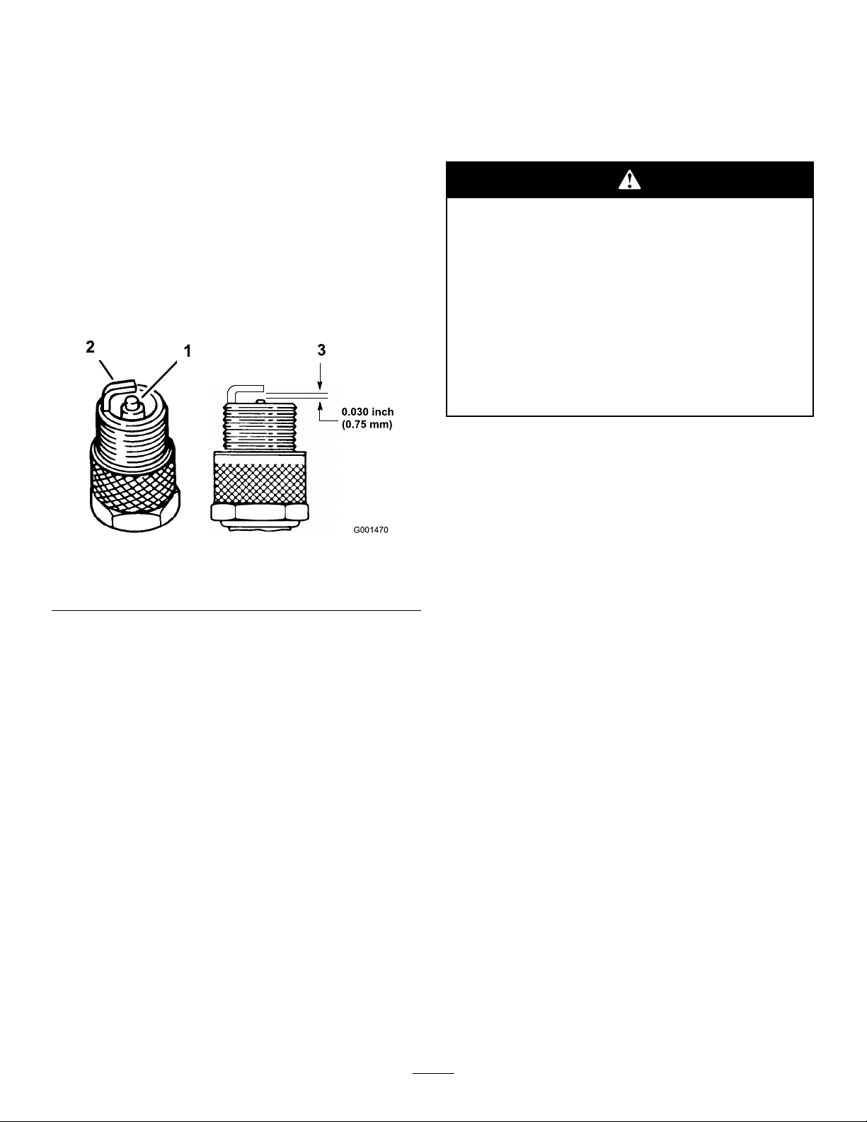
ServicingtheSparkPlugs
Checkthesparkplugsafterevery100operatinghours.
Ensurethattheairgapbetweenthecenterandside
electrodesiscorrectbeforeinstallingthesparkplug.
Useasparkplugwrenchforremovingandinstallingthe
sparkplugsandagappingtool/feelergaugetocheckand
adjusttheairgap.Installanewsparkplugsifnecessary.
Type:Champion®RCJ8YorequivalentAirGap:
0.030inch(0.75mm)
ChangingtheOilFilter
ServiceInterval:Every200hours
Replacetheoillterevery200operatinghoursorevery
otheroilchange.
Note:Changetheoilltermorefrequentlywhenthe
operatingconditionsareextremelydustyorsandy .
1.Draintheoilfromtheengine;refertoChangingthe
EngineOil.
2.Removetheoldlter(Figure29).
RemovingtheSparkPlugs
1.DisengagethePTOandsettheparkingbrake.
2.Stoptheengine,removethekey,andwaitforall
movingpartstostopbeforeleavingtheoperating
position.
3.Disconnectthewiresfromthesparkplugs
(Figure30).
1.Oillter
Figure29
Figure30
2.Adapter
1.Spark-plugwire/sparkplug
27
Page 28
4.Cleanaroundthesparkplugstopreventdirtfrom
fallingintotheengineandpotentiallycausing
damage.
5.Removethesparkplugsandthemetalwashers.
CheckingtheSparkPlugs
ServiceInterval:Every100hours
FuelSystem
Maintenance
DrainingtheFuelTank
1.Lookatthecenterofthesparkplugs(Figure31).
Ifyouseelightbrownorgrayontheinsulator,the
engineisoperatingproperly .Ablackcoatingonthe
insulatorusuallymeansthattheaircleanerisdirty.
2.Ifneeded,cleanthesparkplugwithawirebrushto
removecarbondeposits.
Figure31
1.Centerelectrodeinsulator3.Airgap(nottoscale)
2.Sideelectrode
Incertainconditions,gasolineisextremely
ammableandhighlyexplosive.Areor
explosionfromgasolinecanburnyouand
othersandcandamageproperty.
•Draingasolinefromthefueltankwhenthe
engineiscold.Dothisoutdoorsinanopen
area.Wipeupanygasolinethatspills.
•Neversmokewhendraininggasoline,and
stayawayfromanopenameorwherea
sparkmayignitethegasolinefumes.
1.Parkthemachineonalevelsurface,toassurefuel
tankdrainscompletely.Thendisengagethepower
takeoff(PTO),settheparkingbrake,andturnthe
ignitionkeytooff.Removethekey.
2.Closethefuelshut-offvalveatthefueltank
(Figure32).
3.Squeezetheendsofthehoseclamptogether
andslideitupthefuellineawayfromfuellter
(Figure32).
Important:Alwaysreplacethesparkplugs
whenithaswornelectrodes,anoilylmonit,
orhascracksintheporcelain.
3.Checkthegapbetweenthecenterandsideelectrodes
(Figure31).Bendthesideelectrode(Figure31)if
thegapisnotcorrect.
InstallingtheSparkPlugs
1.Installthesparkplugsandthemetalwasher.Ensure
thattheairgapissetcorrectly.
2.Tightenthesparkplugsto16ft-lb(22N-m).
3.Connectthewirestothesparkplugs(Figure31).
4.Pullthefuellineoffthefuellter(Figure32).Open
thefuelshut-offvalveandallowthegasolinetodrain
intoagascanordrainpan.
Note:Nowisthebesttimetoinstallanewfuellter
becausethefueltankisempty.RefertoReplacing
theFuelFilter.
5.Installthefuellineontothefuellter.Slidethehose
clampclosetothevalvetosecurethefuelline.
6.Wipeupanyspilledfuel.
28
Page 29

Figure32
1.Fuelshut-offvalve2.Clamp
ServicingtheFuelFilter
Figure33
1.Hoseclamp3.Filter
2.Fuelline
Replacethefuellterafterevery200operatinghoursor
yearly,whicheveroccursrst.
ReplacingtheFuelFilter
ServiceInterval:Every200hours
Neverinstalladirtylterifitisremovedfromthefuel
line.
Note:Notehowthefuellterisinstalledinorderto
installthenewltercorrectly.
Note:Wipeupanyspilledfuel.
1.DisengagethePTOandsettheparkingbrake.
2.Stoptheengine,removethekey,andwaitforall
movingpartstostopbeforeleavingtheoperating
position.
3.Closefuelshut-offvalveatthefueltank(Figure32).
4.Squeezetheendsofthehoseclampstogetherand
slidethemawayfromthelter(Figure33).
5.Removethelterfromthefuellines.
6.Installanewlterandmovethehoseclampsclose
tothelter.
7.Openfuelshut-offvalveatfueltank(Figure32).
8.Checkforfuelleaksandrepairifneeded.
9.Wipeupanyspilledfuel.
29
Page 30

ElectricalSystem
Maintenance
ServicingtheBattery
Checktheelectrolytelevelinthebatteryevery25hours.
Alwayskeepthebatterycleanandfullycharged.Use
apapertoweltocleanthebatterycase.Ifthebattery
terminalsarecorroded,cleanthemwithasolutionof
fourpartswaterandonepartbakingsoda.Applyalight
coatingofgreasetothebatteryterminalstoprevent
corrosion.
Voltage:12V
Warning
CALIFORNIA
Proposition65Warning
Batteryposts,terminals,andrelated
accessoriescontainleadandleadcompounds,
chemicalsknowntotheStateofCalifornia
tocausecancerandreproductiveharm.
Washhandsafterhandling.
Incorrectbatterycableroutingcoulddamage
themachineandcablescausingsparks.Sparks
cancausethebatterygassestoexplode,
resultinginpersonalinjury.
•AlwaysDisconnectthenegative(black)
batterycablebeforedisconnectingthe
positive(red)cable.
•AlwaysReconnectthepositive(red)battery
cablebeforereconnectingthenegative
(black)cable.
1.DisengagethePTOandsettheparkingbrake.
2.Stoptheengine,removethekey,andwaitforall
movingpartstostopbeforeleavingtheoperating
position.
3.Lifttheblackrubbercoveronthenegativecable.
Disconnectthenegativebatterycablefromthe
negative(-)batteryterminal(Figure34).
4.Slidetheredterminalbootoffthepositive(red)
batteryterminal.Thenremovethepositive(red)
batterycable(Figure34).
Batteryelectrolytecontainssulfuricacidwhich
isadeadlypoisonandcausessevereburns.
Donotdrinkelectrolyteandavoidcontactwith
skin,eyesorclothing.Wearsafetyglassesto
shieldyoureyesandrubberglovestoprotect
yourhands.
RemovingtheBattery
Batteryterminalsormetaltoolscouldshort
againstmetalmachinecomponentscausing
sparks.Sparkscancausethebatterygassesto
explode,resultinginpersonalinjury.
•Whenremovingorinstallingthebattery,do
notallowthebatteryterminalstotouchany
metalpartsofthemachine.
5.Removethebatteryholddownplate(Figure34)and
removethebattery.
InstallingtheBattery
1.Placethebatterontothemachine(Figure34).
2.Securethebatterywiththeholddownplate,j-bolts,
andlocknuts.
3.First,installthepositive(red)batterycableto
positive(+)batteryterminalwithanut,washerand
bolt(Figure34).Slidetherubbercoveroverthepost.
4.Theninstallthenegativebatterycableandground
wiretothenegative(-)batteryterminalwithanut,
washerandbolt(Figure34).Slidetherubbercover
overthepost.
•Donotallowmetaltoolstoshortbetween
thebatteryterminalsandmetalpartsofthe
machine.
30
Page 31

Figure35
1.Ventcaps3.Lowerline
2.Upperline
2.Iftheelectrolyteislow ,addtherequiredamountof
distilledwater;refertoAddingWatertotheBattery
in,page.
AddingWatertotheBattery
Thebesttimetoadddistilledwatertothebatteryisjust
beforeyouoperatethemachine.Thisletsthewatermix
thoroughlywiththeelectrolytesolution.
1.Removethebatteryfromthemachine;referto
RemovingtheBatteryin,page.
Figure34
1.Negativecable7.Positivecable
2.Nut(1/4in.)
3.Nut(5/16in.)
4.Bolt10.Batteryholddown
5.Rubbercover(red)
6.Rubbercover(black)
8.Batteryholddownplate
9.Washer
11.Battery
CheckingtheBatteryElectrolyteLevel
ServiceInterval:Every25hours
Batteryelectrolytecontainssulfuricacidwhich
isadeadlypoisonandcausessevereburns.
•Donotdrinkelectrolyteandavoidcontact
withskin,eyesorclothing.Wearsafety
glassestoshieldyoureyesandrubbergloves
toprotectyourhands.
Important:Neverllthebatterywithdistilled
waterwhilethebatteryisinstalledinthe
machine.Electrolytecouldbespilledonother
partsandcausecorrosion.
2.Cleanthetopofthebatterywithapapertowel.
3.Removetheventcapsfromthebattery(Figure35).
4.Slowlypourdistilledwaterintoeachbatterycell
untiltheelectrolytelevelisuptotheUpperline
(Figure35)onthebatterycase.
Important:Donotoverllthebatterybecause
electrolyte(sulfuricacid)cancausesevere
corrosionanddamagetothechassis.
5.Waitvetotenminutesafterllingthebatterycells.
Adddistilledwater,ifnecessary,untiltheelectrolyte
levelisuptotheUpperline(Figure35)onthe
batterycase.
6.Reinstallthebatteryventcaps.
ChargingtheBattery
•Fillthebatterywherecleanwaterisalways
availableforushingtheskin.
1.Lookatthesideofthebattery.Theelectrolytemust
beuptotheupperline(Figure35).Donotallowthe
electrolytetofallbelowtheLowerline(Figure35).
Chargingthebatteryproducesgassesthatcan
explode.
Neversmokenearthebatteryandkeepsparks
andamesawayfrombattery.
31
Page 32

Important:Alwayskeepthebatteryfullycharged
(1.265specicgravity).Thisisespeciallyimportant
topreventbatterydamagewhenthetemperatureis
below32°F(0°C).
1.Removethebatteryfromthechassis;referto
RemovingtheBattery.
2.Checktheelectrolytelevel;refertoCheckingthe
ElectrolyteLevel.
3.Makesurethellercapsareinstalledinbattery.
Chargebatteryfor1hourat25to30ampsor6
hoursat4to6amps.
4.Whenthebatteryisfullycharged,unplugthecharger
fromtheelectricaloutlet,thendisconnectthe
chargerleadsfromthebatteryposts(Figure36).
5.Installthebatteryontothemachineandconnectthe
batterycables,refertoInstallingtheBattery.
Note:Donotrunthemachinewiththebattery
disconnected,electricaldamagemayoccur.
Figure36
1.PositiveBatteryPost
2.NegativeBatteryPost
3.Red(+)ChargerLead
4.Black(-)ChargerLead
ServicingtheFuses
Figure37
1.Redwire3.Fuse,25amp,bladetype
2.Fuse,30amp,bladetype4.Violetwire
Theelectricalsystemisprotectedbyfuses.Itrequires
nomaintenance.Ifafuseblows,checkthecomponent
orcircuitforamalfunctionorshort.
1.Removethecoverunderthecontrolpanel.
2.Pulloutonthefusetoremoveorreplaceit
(Figure37).
3.Installthecoverunderthecontrolpanel.
Note:Ensurethecorrectsizefuseisinstallwiththe
correctwirecolorasshowninFigure37.
32
Page 33

DriveSystem
Maintenance
AdjustingtheTracking
1.Ifthemachinedoesnottrackstraight,adjustment
isrequired.
2.Checkthereartirepressure.RefertoCheckingthe
TirePressure.
3.Loosenthewingnutsontherightcontrolrodand
rotatetheturnbuckleinorouttoensuretheright
sidecontrolleveriscenteredintheneutrallock
position.Securetheturnbuckleinpositionwiththe
wingnuts(Figure38).
4.Loosenthewingnutsontheleftcontrolrodand
rotatetheturnbuckleinorouttochangethetracking.
Securetheturnbuckleinpositionwiththewingnuts
(Figure38).
5.Checkforpropertracking.Adjusttheleftcontrol
rodifachangeisneeded.
Figure39
ReplacingtheCasterWheel
ForkBushings
Thecasterwheelforksaremountedinbushingspressed
intothetopandbottomofthecarrierframemounting
pivottubes.Tocheckthebushings,movethecaster
forksbackandforthandside-to-side.Ifacasterforkis
loose,thebushingsarewornandmustbereplaced.
1.Raisethecuttingunitsothecasterwheelsareoff
theoor,thensupportthefrontofthemowerwith
jackstands.
2.Removethelockingpinandspacer(s)fromthetop
ofthecasterwheelfork(Figure40).
Figure38
1.Turnbuckle
2.Bottomwingnut
3.Topwingnut(lefthand
threaded)
CheckingtheTirePressure
ServiceInterval:Every50hours
Checkthepressureatthevalvestemafterevery
50operatinghoursormonthly,whicheveroccursrst
(Figure39).
Maintaintheairpressureinthereartiresat12-14psi
(83-97kPa).Uneventirepressurecancauseanuneven
cut.
Note:Thefronttiresaresemi-pneumatictiresanddo
notrequireairpressuremaintenance.
Figure40
1.LockingPin
2.Spacers4.Casterwheelfork
3.Pullthecasterwheelforkoutofthemountingtube,
leavingthespacer(s)onthebottomofthefork.
Rememberthelocationofthespacersoneachfork
33
3.Carrierframepivottube
Page 34

toensurecorrectinstallation,andtomaintainalevel
deck.
4.Insertapinpunchintothemountingtubeand
carefullydriveoutthebushings(Figure41).Clean
theinsideofthemountingtube.
Figure41
1.MountingTube2.Bushing
Figure42
1.Locknut
2.WheelBolt5.RollerBearing
3.Bushing
4.SpannerBushing
2.Removeonebushing,thenpullthespannerbushing
androllerbearingoutofthewheelhub(Figure42).
5.Greasetheinsideandoutsideofthenewbushings.
Useahammerandatplatetocarefullydrivethe
bushingsintothepivottubes.
6.Inspectthecasterwheelforkforwearandreplace
ifnecessary(Figure40).
7.Slidethecasterwheelforkthroughthebushingsin
themountingtube.Replacethespacer(s)ontothe
forkandsecurewiththeretainingring(Figure40).
Important:Theinsidediameterofthebushings
maycollapseslightlywheninstalled.Ifthe
casterwheelforkdoesnotslideintothenew
bushings,reambothbushingstoaninside
diameterof1.126inch(29mm).
8.Greasethettingonthecarrierframepivottubes
usingNo.2generalpurposelithiumbaseor
molybdenumbasegrease.
ServicingtheCasterWheel
andBearings
Thecasterwheelsrotateonarollerbearingsupportedby
aspannerbushing.Ifthebearingiskeptwelllubricated,
wearwillbeminimal.Failuretokeepthebearingwell
lubricatedwillcauserapidwear.Awobblycasterwheel
usuallyindicatesawornbearing.
1.Removethelocknutandwheelboltholdingthe
casterwheeltothecasterfork(Figure42).
3.Removetheotherbushingfromthewheelhub
andcleananygreaseanddirtfromthewheelhub
(Figure42).
4.Inspecttherollerbearing,bushings,spannerbushing
andinsideofthewheelhubforwear.Replaceany
defectiveorwornparts(Figure42).
5.Toassemble,placeonebushingintothewheelhub.
Greasetherollerbearingandspannerbushingand
slidethemintothewheelhub.Placethesecond
bushingintothewheelhub(Figure42).
6.Installthecasterwheelintothecasterforkand
securewiththewheelboltandlocknut.Tightenthe
locknutuntilthespannerbushingbottomsagainst
theinsideofthecasterforks(Figure42).
7.Greasethettingonthecasterwheel.
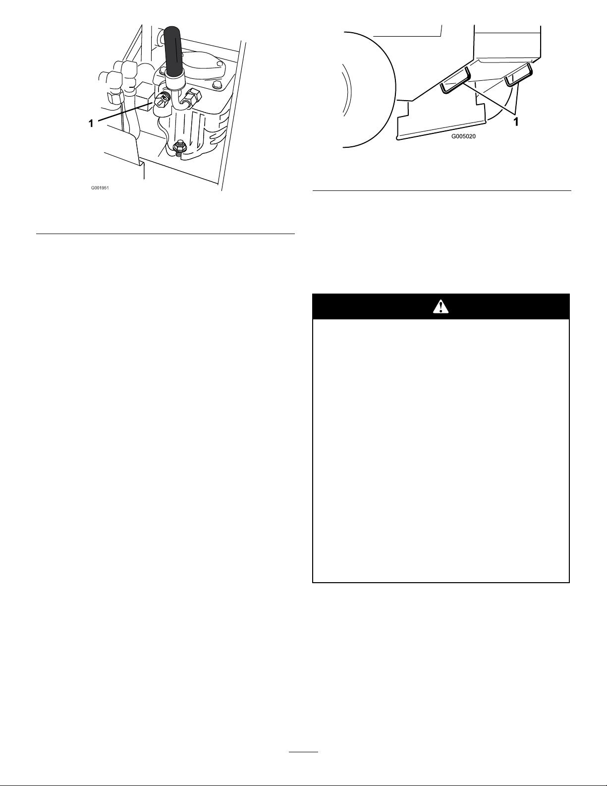
AdjustingtheElectricClutch
ServiceInterval:Every100hours
Theclutchisadjustabletoensureproperengagement
andproperbraking.Checkadjustmentafterevery100
hoursofoperation.
1.Inserta0.015–0.021inch(0.381–0.533mm)feeler
gaugethroughoneinspectionslotinthesideofthe
assembly.Makesureitisbetweenthearmatureand
therotorfrictionsurfaces.
34
Page 35

2.Tightenthelocknutsuntilthereisslightbindingon
thefeelergaugebutitcanbemovedeasilywithinthe
airgap(Figure43).
3.Repeatthisfortheremainingslots.
CoolingSystem
Maintenance
4.Checkeachslotagainandmakeslightadjustments
untilthefeelergaugebetweentherotorandarmature
withveryslightcontactbetweenthem.
Figure43
1.Adjustingnut3.Feelergauge
2.Slot
CleaningtheAirIntakeScreen
ServiceInterval:Beforeeachuseordaily
Beforeeachuseremoveanybuild-upofgrass,dirt
orotherdebrisfromthecylinderandcylinderhead
coolingns,airintakescreenonywheelend,and
carburetor-governorleversandlinkage.Thiswillhelp
insureadequatecoolingandcorrectenginespeedand
willreducethepossibilityofoverheatingandmechanical
damagetotheengine.
35
Page 36

BrakeMaintenance
ServicingtheBrake
Beforeeachuse,checkbrakesonbothalevelsurface
andslope.
Alwayssettheparkingbrakewhenyoustopthemachine
orleaveitunattended.Iftheparkingbrakedoesnot
holdsecurely,anadjustmentisrequired.
CheckingtheParkingBrake
ServiceInterval:Beforeeachuseordaily
1.Parkthemachineonalevelsurface,disengagethe
PTO.
2.Stoptheengine,removethekey,andwaitforall
movingpartstostopbeforeleavingtheoperating
position.
3.Applytheparkingbrake.Settingtheparkingbrake
shouldtakeareasonableamountofforce.Ifthe
parkingbrakedoesnotholdsecurely,anadjustment
isrequired.RefertoAdjustingtheParkingBrake.
Note:Whenthebrakeisengaged,thebrakehandle
shouldbeinthe1o’clockposition(Figure44).
9.Tightenthetopandbottomjamnuts(Figure44).
10.Checkthebrakeoperationagain;refertoChecking
theBrake.
Figure44
1.Parkingbrakelever
(releasedposition)
2.1o’clockposition6.Yoke
3.Haripincotter7.JamNut
4.Lowerbrakelever8.Brakerod
5.Clevispin
AdjustingtheBrakes
Iftheparkingbrakedoesnotholdsecurely,an
adjustmentisrequired.
1.Parkthemachineonalevelsurface,disengagethe
PTO,andsettheparkingbrake.
2.Stoptheengine,removethekey,andwaitforall
movingpartstostopbeforeleavingtheoperating
position.
3.Checkthebrakebeforeyouadjustit;referto
CheckingtheBrakes.
4.Releasetheparkingbrake;refertoReleasingthe
ParkingBrakein,page.
5.Loosenthetopandbottomjamnuts(Figure44).
6.Toadjustthebrake,removethehairpincotterand
clevispinfromthelowerbrakelever(Figure44).
7.Rotatethebrakerodintheyokes.Totightenthe
brake,lengthentherodbetweentheyokes.To
loosenthebrake,shortentherodbetweentheyokes
(Figure44).
Note:Thebrakerodshouldbethreadedintoboth
yokesthesamedistance.
8.Securetheyoketolowerbrakeleverwiththehairpin
cotterandclevispin(Figure44).
36
Page 37

BeltMaintenance
ReplacingtheMowerBelt
ServiceInterval:Every50hours
Squealingwhenthebeltisrotating,bladesslippingwhen
cuttinggrass,frayedbeltedges,burnmarksandcracks
aresignsofaworndeckbelt.Replacethedeckbeltif
anyoftheseconditionsareevident.
1.DisengagethePTOandsettheparkingbrake.
2.Stoptheengine,removethekey,andwaitforall
movingpartstostopbeforeleavingtheoperating
position.
3.Unlatchandremovethecarrierframecover.
4.Unlatchandremovethebeltcovers.
5.RemovethePTOdrivebelt.RefertoReplacingthe
PTODriveBelt.
6.Disconnecttheidlerarmspringtorelievetensionon
theidlerarmandidlerpulley,thenremovetheworn
mowerbelt(Figure45orFigure46).
7.Installthenewmowerbeltaroundthetwooutside
spindlepulleys,theidlerpulley,andinthelower
grooveofthedoublespindlepulley(Figure45or
Figure46).
8.Connecttheidlerarmspring(Figure45orFigure46).
9.InstallthePTOdrivebelt.RefertoReplacingthe
PTODriveBelt.
10.Adjustthebeltguidean1/8inch(3mm)fromthe
belt(Figure45orFigure46).
11.Installthebeltcoversontothecuttingunitand
securethelatches.
Figure45
40inch,48inch,and52inchMowerDeckshown
1.Outsidepulley
2.PTODriveBelt
3.Idlerarmspring
4.Mowerdeckbelt
5.Beltguide
6.Centerspindlepulley
12.Installthecarrierframecoverontothecuttingunit
andsecurethelatches.
Figure46
36inchMowerDeckshown
1.Mowerdeckbelt4.Idlerarmspring
2.PTODriveBelt
3.Drivebeltpulley
5.Drivebeltpulley
ReplacingthePTODriveBelt
ServiceInterval:Every50hours
Squealingwhenthebeltisrotating,bladesslippingwhen
cuttinggrass,frayedbeltedges,burnmarksandcracks
37
Page 38

aresignsofaworndrivebelt.Replacethedrivebeltif
anyoftheseconditionsareevident.
1.DisengagethePTOandsettheparkingbrake.
2.Stoptheengine,removethekey,andwaitforall
movingpartstostopbeforeleavingtheoperating
position.
3.Unlatchandremovethecarrierframecover.
4.Unlatchandremovethebeltcovers.
5.Removetheheatshieldfromtheenginedeckand
carrierframe.
6.Rollthebeltoffofthecenterpulleyonthemower
deck(Figure47).RefertoFigure48torollthebelt
offleftpulleyfora36inchmowerdeck.Usecaution
whenremovingthebeltastensionwillincrease
becauseofthespringloadedidlerpulley.
7.Removethebeltfromtheenginepulleyandthe
springloadedidlerpulley(Figure47).Referto
Figure48toremovethebeltfromthe36inchmower
deckpulleys.
Figure47
40inch,48inch,and52inchMowerDeckshown
1.PTOdrivebeltguide4.PTOengagementpulley
2.PTOdriveBelt5.PTOdrivebeltidlerpulley
3.Idlerspring
6.Centerspindlepulley
8.Installthenewbeltontotheenginepulleyandspring
loadedidlerpulley(Figure47).
9.Rollthebeltontothecenterpulleyonthemower
deck(Figure47).Usecautionwheninstallthebelt
astensionwillincreasebecauseofthespringloaded
idlerpulley.RefertoFigure48torollthenewbelt
ontotheleftpulleyfora36inchmowerdeck.
10.Installtheheatshieldtotheenginedeckandcarrier
frame.
11.Adjustthebeltguidean1/8inch(3mm)fromthe
beltfor40,48and52inchmowerdecks(Figure47).
12.Installthebeltcoversontothecuttingunitand
securethelatches.
13.Installthecarrierframecoverontothecarrierframe
andsecurethelatches.
1.Mowerdeckbelt
2.PTODriveBelt
3.Idlerarmandspring
Figure48
36inchMowerDeckshown
4.Clutchpulley
5.Idlerpulley
AdjustingthePTODriveBelt
IdlerSpringAnchor
ThepositionofthePTOidlercanbeadjustedto
increaseordecreasebelttension.
38
Page 39

UseFigure49fortheidlerpositionoptions.
Figure49
1.PTOdrivebeltidlerpulley4.Mosttensionforwornbelts
2.PTOdriveBelt5.Mediumtensionfornormal
3.Idlerspring
beltconditions
6.Leasttensionfornewbelts
Figure50
1.Hydraulicpumps
2.Idlerpulley6.Pivotbolt
3.Clutchretainer
4.Tensionspring8.Pumpdrivebelt
5.Clutchwireconnector
7.Drivepulley
7.Unhooktheidlerspringfromtheframe(Figure50).
ReplacingthePumpDriveBelt
ServiceInterval:Every50hours
1.DisengagethePTOandsettheparkingbrake.
2.Stoptheengine,removethekey,andwaitforall
movingpartstostopbeforeleavingtheoperating
position.
3.RemovePTOdrivebelt.RefertoReplacingthe
PTODriveBeltinthe,page.
4.Raisethemachineandsupportitwithjackstands.
5.Disconnecttheclutchwireconnectorfromthewire
harness.
6.Disconnecttheclutchretainerfromtheenginedeck
(Figure50).
8.Installthenewbeltaroundclutchandthetwodrive
pulleys.
9.Installtheidlerspringbetweenidlerarmandframe
bracket(Figure50).
10.Installtheclutchretainertotheenginedeck
(Figure50).
11.Connecttheclutchwireconnectortothewire
harness.
12.InstallthePTOdrivebelt.
39
Page 40

ControlsSystem
Maintenance
AdjustingtheMotionControl
HandlePositions
AdjustingtheRightSideMotionControl
Lever
Ifthemotioncontrolleversdonotalignhorizontally,
adjusttherightsidemotioncontrollever.
Note:Adjustthehorizontalalignmentbeforethefront
tobackalignment.
1.DisengagethePTO,movetherightsidemotion
controllevertotheneutralpositionandsetthe
parkingbrake.
2.Stoptheengine,removethekey,andwaitforall
movingpartstostopbeforeleavingtheoperating
position.
3.Pushtherightmotioncontrolleverdownoutof
lockedneutralposition(Figure51).
4.Checkifitalignshorizontallywiththeleftmotion
controllever(Figure51).
Figure51
1.Leftmotioncontrollever3.Checkthehorizontal
2.Rightmotioncontrollever
inneutrallockedposition
alignmenthere
4.Rightmotioncontrollever
Figure52
1.Cam
2.Nutandbolt
3.Wingnut
4.Turnbuckle
5.Switchscrews
9.Afterthecamisadjusted,theleverswitchneedsto
bechecked.
10.Checkthegapbetweenthecontrolleverandswitch
asshowninFigure53.Thegapneedstobean1/8
inch(3mm).
11.Ifneeded,loosenthescrewsholdingtheswitchand
adjusttheswitch.
12.Tightenthescrewsandinstallthecoverunderthe
controlpanel.
5.Toadjusttherightmotioncontrolleverhorizontally,
thecamneedstobeadjusted.
6.Removethecoverunderthecontrolpanel.
7.Loosenthenutandboltholdingthecam(Figure52).
8.Adjustthecamuntilitalignswiththeleftmotion
controlleverandtightenthenutandboltforthe
cam.
40
Page 41

1.Rightsidemotioncontrol
leverpivotshownunder
controls
2.Rightsidemotioncontrol
lever
Figure53
3.1/8inch(3mm)gap
4.Switch
neededbetweenswitch
andcontrollever
Figure54
1.Leftmotioncontrollever
2.Rightmotioncontrollever4.Alignthecontrollevers
3.Neutrallockedposition
fronttobackhere
AdjustingtheNeutralPostionforthe
MotionControlLevers
Important:Ensurethetrackingofthemoweris
correctafteradjustingthemotioncontrollevers.
Afteradjustingthetracking,themotioncontrol
leversmaynotaligntheexactlyfronttoback
(Figure54).
Ifthemotioncontrolleversdonotalignfronttoback,
ortherightsidecontrolleverdoesnotmoveeasilyinto
theneutrallockposition,adjustmentisrequired.Adjust
eachleverandcontrolrodseparately.
Note:Adjustthehorizontalalignmentbeforethefront
tobackalignment.
1.Afterthehorizontalalignmentisnished,checkthe
fronttobackalignment(Figure54).
2.Loosenthewingnutsontherightcontrolrodand
rotatetheturnbuckleinorouttoensuretheright
sidecontrolleveriscenteredintheneutrallock
position.Securetheturnbuckleinpositionwiththe
wingnuts(Figure55).
3.Loosenthewingnutsontheleftcontrolrodand
rotatetheturnbuckleinorouttochangethetracking.
Securetheturnbuckleinpositionwiththewingnuts
(Figure55).
Figure55
1.Turnbuckle
2.Bottomwingnut
3.Topwingnut(lefthand
4.Checkforpropertracking.Adjusttheleftcontrol
rodifachangeisneeded.RefertoAdjustingthe
TrackingintheOperationSection.
41
threaded)
Page 42

HydraulicSystem
Maintenance
5.Removecapfromllerneck.Lookinsidetocheck
theuidlevelinthereservoir.(Figure56).
6.Adduidtothereservoiruntilitreachesthecold
levelofthebafe.
ServicingtheHydraulic
System
CheckingtheHydraulicFluid
ServiceInterval:Aftertherst8hours
Every25hours
Checkthehydraulicuidlevelasfollows:
•Checkthehydraulicuidlevelbeforeengineisrst
started.
•Checkthehydraulicuidlevelafterrst8operating
hours.
•Checkthehydraulicuidlevelafterevery25
operatinghours.
FluidType:Mobil115W -50syntheticmotoroilor
equivalentsyntheticoil.
Important:Useoilspeciedorequivalent.Other
uidscouldcausesystemdamage.
HydraulicSystemOilCapacity:67oz.(2.0l)
Note:Therearetwowaysofcheckingthehydraulicoil.
Oneiswhentheoiliswarmandoneiswhentheoilis
cold.Thebafeinsidethetankhastwolevelsdepending
iftheoiliswarmorcold.
1.Positionmachineonalevelsurface.
2.Disengagethepowertakeoff(PTO)andshutoff
theengine.
3.Waitforallmovingpartstostopbeforeleavingthe
operatingpositionandthensettheparkingbrake.
4.Cleanareaaroundcapandllerneckofhydraulic
tank(Figure56).
7.Runthemachineatlowidlefor15minutestoallow
anyairtopurgeoutofthesystemandwarmuid.
RefertoStartingandStoppingtheEngine.
8.Rechecktheuidlevelwhiletheuidiswarm.If
required,adduidtothereservoiruntilitreaches
thehotlevelofthebafe.
Note:Theuidlevelshouldbetothetopofthehot
levelofthebafe,whentheuidiswarm(Figure56).
9.Installcaponllerneck.
Hydraulicuidescapingunderpressurecan
penetrateskinandcauseinjury.
•Ifhydraulicuidisinjectedintotheskin
itmustbesurgicallyremovedwithinafew
hoursbyadoctorfamiliarwiththistypeof
injury.Gangrenemayresultifthisisnot
done.
•Keepbodyandhandsawayfrompinhole
leaksornozzlesthatejecthighpressure
hydraulicuid.
•Usecardboardorpapertondhydraulic
leaks.
•Safelyrelieveallpressureinthehydraulic
systembeforeperforminganyworkonthe
hydraulicsystem.
•Makesureallhydraulicuidhosesand
linesareingoodconditionandallhydraulic
connectionsandttingsaretightbefore
applyingpressuretohydraulicsystem.
Figure56
1.Cap3.Colduidlevel-full
2.Bafe4.Hotuidlevel-full
ReplacingtheHydraulicFilter
ServiceInterval:Aftertherst8hours
Every200hours
Hothydraulicuidcancausesevereburns.
Allowthehydraulicuidtocoolbefore
performinganymaintenancetothehydraulic
system.
42
Page 43

Changethehydrauliclterasfollows:
•Aftertherst8operatinghours.
•Afterevery200operatinghoursoryearlybefore
storage.
1.DisengagethePTOandsettheparkingbrake.
2.Stoptheengineandwaitforallmovingpartstostop
beforeleavingtheoperatingposition.
Important:Donotsubstituteautomotiveoil
lterorseverehydraulicsystemdamagemay
result.
3.Removehydraulicreservoircapandtemporarily
coveropeningwithaplasticbagandrubberbandto
preventallhydraulicuidfromdrainingout.
4.Locatethelterunderthefueltankandplacedrain
panunderlter(Figure57).
Figure58
1.Hydrauliclter
2.Gasket
3.Adapter
10.Cleanupanyspilleduid.
11.Checktheuidinthereservoir,adduidtothetank
untilitreachesthecoldbafeofthetank.
Important:Useoilspeciedorequivalent.
Otheruidscouldcausesystemdamage.
12.Startengineandletrunforabouttwominutesto
purgeairfromthesystem.Stoptheengineand
checkforleaks.Ifoneorbothwheelswillnotdrive,
refertoBleedingHydraulicSystem.
13.Rechecklevelandadduid,ifrequired.Donot
overll.
Figure57
5.Removetheoldlterandwipethelteradapter
gasketsurfaceclean(Figure58).
6.Applyathincoathydraulicuidtotherubbergasket
onthereplacementlter.
7.Installreplacementhydrauliclterontothelter
adapter.Donottighten.
8.Removeplasticbagfromreservoiropeningand
allowltertollwithhydraulicuid.
9.Whenthehydrauliclterisfull,turntheoillter
clockwiseuntiltherubbergasketcontactsthelter
adapter,thentightenthelteranadditional1/2turn
(Figure58).
BleedingtheHydraulicSystem
Thetractionsystemisselfbleeding,however,itmaybe
necessarytobleedthesystemifuidischangedorafter
workisperformedonthesystem.
1.DisengagethePTOandsettheparkingbrake.
2.Stoptheengineandwaitforallmovingpartstostop
beforeleavingtheoperatingposition.
3.Raisetherearofthemachineupontojackstands
highenoughtoraisethedrivewheelsofftheground.
4.Starttheengineandmovethethrottlecontroltoidle
position.
Ifthedrivewheeldoesnotrotate,itispossibleto
assistthepurgingofthesystembycarefullyrotating
thetireintheforwarddirection.
5.Checkthehydraulicuidlevelasitdropsadduid
asrequiredtomaintaintheproperlevel.
6.Repeatthisprocedurefortheoppositewheel.
7.Thoroughlycleantheareaaroundeachofthecharge
pumphousings.
CheckingtheHydraulicLines
ServiceInterval:Every100hours
43
Page 44

Afterevery100operatinghours,checkhydraulic
linesandhosesforleaks,loosettings,kinkedlines,
loosemountingsupports,wear,weatherandchemical
deterioration.Makenecessaryrepairsbeforeoperating.
MowerDeck
Maintenance
Note:Keepareasaroundhydraulicsystemcleanfrom
grassanddebrisbuildup.
Hydraulicuidescapingunderpressurecan
penetrateskinandcauseinjury.
•Ifhydraulicuidisinjectedintotheskin
itmustbesurgicallyremovedwithinafew
hoursbyadoctorfamiliarwiththistypeof
injury.Gangrenemayresultifthisisnot
done.
•Keepbodyandhandsawayfrompinhole
leaksornozzlesthatejecthighpressure
hydraulicuid.
•Usecardboardorpapertondhydraulic
leaks.
•Safelyrelieveallpressureinthehydraulic
systembeforeperforminganyworkonthe
hydraulicsystem.
•Makesureallhydraulicuidhosesand
linesareingoodconditionandallhydraulic
connectionsandttingsaretightbefore
applyingpressuretohydraulicsystem.
ServicingtheCuttingBlades
Toensureasuperiorqualityofcut,keeptheblades
sharp.Forconvenientsharpeningandreplacement,you
maywanttokeepextrabladesonhand.
Awornordamagedbladecanbreak,anda
pieceofthebladecouldbethrownintothe
operator’sorbystander’sarea,resultingin
seriouspersonalinjuryordeath.
•Inspectthebladesperiodicallyforwearor
damage.
•Replaceawornordamagedblade.
BeforeInspectingorServicingthe
Blades
Parkthemachineonalevelsurface,disengagetheblades
andsettheparkingbrake.Turntheignitionkeytooff.
Removethekeyanddisconnectthesparkplugwires
fromthesparkplugs.
InspectingtheBlades
ServiceInterval:Beforeeachuseordaily
Inspectthebladesevery8hours.
1.Inspectthecuttingedges(Figure59).Iftheedges
arenotsharporhavenicks,removeandsharpenthe
blades.RefertoSharpeningtheBlades.
44
Page 45

Figure60
40inch,48inch,and52inchMowerDeckshown
Figure59
1.CuttingEdge3.Wear/slotformingin
curvedarea
2.Sail4.Crackinthecurvedarea
2.Inspecttheblades,especiallythecurvedarea
(Figure59).Ifyounoticeanycracks,wear,ora
slotforminginthisarea(item3inFigure59),
immediatelyinstallanewblade.
CheckingforBentBlades
1.DisengagethePTO,movethemotioncontrollevers
totheneutrallockedpositionandsettheparking
brake.
2.Stoptheengine,removethekey,andwaitforall
movingpartstostopbeforeleavingtheoperating
position.
3.Rotatethebladesuntiltheendsfaceforwardand
backward.Measurefromalevelsurfacetothe
cuttingedge,positionA,oftheblades(Figure60
).Notethisdimension.For36inchmowerdecks
useFigure61.
1.Measureherefromblade
tohardsurface
36inchMowerDeckshown
2.PositionA
Figure61
4.Rotatetheoppositeendsofthebladesforward.
5.Measurefromalevelsurfacetothecuttingedgeof
thebladesatthesamepositionasinstep3above.
Thedifferencebetweenthedimensionsobtainedin
steps3and4mustnotexceed1/8inch(3mm).If
thisdimensionexceeds1/8inch(3mm),theblade
isbentandmustbereplaced;refertoRemovingthe
BladesandInstallingtheBlades.
45
Page 46

Abladethatisbentordamagedcouldbreak
apartandcouldseriouslyinjureorkillyouor
bystanders.
•Alwaysreplacebentordamagedbladewith
anewblade.
•Neverleorcreatesharpnotchesinthe
edgesorsurfacesofblade.
RemovingtheBlades
Bladesmustbereplacedifasolidobjectishit,ifthe
bladeisoutofbalanceorisbent.T oensureoptimum
performanceandcontinuedsafetyconformanceof
themachine,usegenuineT ororeplacementblades.
Replacementbladesmadebyothermanufacturersmay
resultinnon-conformancewithsafetystandards.
1.Holdthebladeendusingaragorthickly-padded
glove.
2.For40and48inchmowerdecks,removetheblade
bolt,curvedwasher,andbladefromthespindle
shaft(Figure62).
Figure63
36inchand52inchMowerDecks
1.SailAreaofBlade4.Curvedwasher
2.Blade5.BladeBolt
3.Bladestiffener
Figure62
40inchand48inchMowerDecks
1.SailAreaofBlade3.Curvedwasher
2.Blade4.BladeBolt
3.For36and52inchmowerdecks,removetheblade
bolt,curvedwasher,bladestiffener,andbladefrom
thespindleshaft(Figure63).
SharpeningtheBlades
1.Usealetosharpenthecuttingedgeatbothends
oftheblade(Figure64).Maintaintheoriginalangle.
Thebladeretainsitsbalanceifthesameamountof
materialisremovedfrombothcuttingedges.
Figure64
1.Sharpenatoriginalangle
2.Checkthebalanceofthebladebyputtingitona
bladebalancer(Figure65).Ifthebladestaysina
horizontalposition,thebladeisbalancedandcanbe
used.Ifthebladeisnotbalanced,lesomemetaloff
theendofthesailareaonly(Figure62).Repeatthis
procedureuntilthebladeisbalanced.
46
Page 47

Figure65
1.Blade2.Balancer
InstallingtheBlades
1.Installthebladeontothespindleshaft(Figure62).
Important:Thesailpartoftheblademustbe
pointingupward,towardtheinsideofthemower
toensurepropercutting(Figure62).
2.For40inchand48inchmowerdecks,installthe
blade,curvedwasher,andbladebolt(Figure62).
3.For36inchand52inchmowerdecks,installthe
blade,stiffener,curvedwasher,andbladebolt
(Figure63).
4.Torquethebladeboltto85-110ft-lb(115-140N-m).
FrameSetUp
CheckingtheCarrierFrameandEngine
DeckAlignment
Note:MisalignmentcancauseexcesswearonthePTO
drivebelt.
1.DisengagethePTOandsettheparkingbrake.
2.Stoptheengine,removethekey,andwaitforall
movingpartstostopbeforeleavingtheoperating
position.
3.Placealongstraightedgeontopoftheenginedeck
asshowninFigure66.
4.Atthecarrierframecrosschannel,measurethe
heightatlocationA(Figure66).Thismeasurement
mustbe1-5/16inch(33mm),plusorminusa1/4
inch(6mm).
5.IftheheightatlocationAisnotcorrect,adjustment
isneeded.
6.Loosenthecarrierframemountingboltsonboth
sidesofthemachine(Figure66).
CorrectingtheMowerQuality
ofCut
Ifonedeckbladecutslowerthantheother,correctas
follows.
Note:Tireairpressureiscriticalintheseprocedures.
Makesurealltireshavecorrectpressure.
1.DisengagethePTOandsettheparkingbrake.
2.Stoptheengine,removethekey,andwaitforall
movingpartstostopbeforeleavingtheoperating
position.Disconnectthesparkplugwire(s)from
thesparkplug(s).
3.Adjustthetirepressureinthereartiresto
specications;referto,page.
4.Checkthatthebladesandspindleshaftsarenot
bent.RefertoCheckingforBentBlades.
5.Settheheight-of-cuttothe4inch(101.6mm)
position.RefertoAdjustingtheHeight-Of-Cutin,
page.
7.Alignthecarrierframeandenginedecktomatch
1-5/16inch(33mm),plusorminusa1/4inch(6
mm)atlocationA(Figure66).
8.Tightenthecarrierframemountingboltsonboth
sidesofthemachine.
6.PerformthestepsinthefollowingsectionsFrame
SetUp,CheckingFront-to-RearPitch,andChecking
Side-to-SideLeveling.
Figure66
1.CarrierFrame4.LocationA,1-5/16inch
2.Topofenginedeck5.Straightedge
3.Carrierframemounting
bolts
47
(33mm)±1/4inch(6mm)
6.Carrierframecross
channel
Page 48

CheckingtheEngineDeckHeight
1.DisengagethePTOandsettheparkingbrake.
2.Stoptheengine,removethekey,andwaitforall
movingpartstostopbeforeleavingtheoperating
position.
3.Adjustthetirepressureinthereartiresto
specications;referto,page.
4.MeasureenginedeckheightatlocationA(Figure67).
5.MeasureenginedeckheightatlocationB(Figure67).
6.IftheheightatlocationAandBarenotthesame,
changetirepressureslightlytomakethemthesame.
Figure67
1.Backviewofmachine
2.Topofenginedeck4.Sameheightatlocations
3.Tires
AandB
CheckingtheCarrierFrame
Front-to-RearPitch
Figure68
1.CarrierFrame
2.1/8inch-3/8inch(3-10
mm)pitchover24inch(61
cm)length
3.24inches(61cm)6.Casterspacers
4.HeightatlocationsAand
B
5.CasterWheel
2.MeasurecarrierframeheightatlocationA
(Figure68).
3.MeasurecarrierframeheightatlocationB
(Figure68).
4.TheheightatlocationAmustbean1/8-3/8inch(3
mm-10mm)lowerthanlocationB(Figure68).
5.Ifthecarrierframeisnotcorrect,movecaster
spacerstomakeitan1/8-3/8inch(3-10mm)pitch
(Figure68).Movespacersfromtoporbottomto
makethecorrectpitch.
6.Thetirepressuremayalsobeadjustedslightlyto
makean1/8-3/8inch(3-10mm)pitch.
Thecarrierframemusthaveapitchbetween1/8inch
(3mm)to3/8inch(9mm)overthelengthof24inches
(61cm)onthecarrierframe(Figure68).
1.Measureout24inches(61cm)onthecarrierframe
(Figure68).
CheckingtheCarrierFrame
Side-to-SideHeight
Thecarrierframeneedstobeparallelside-to-sidefrom
theground.
1.DisengagethePTOandsettheparkingbrake.
2.Stoptheengine,removethekey,andwaitforall
movingpartstostopbeforeleavingtheoperating
position.
3.Adjustthetirepressureinthereartiresto
specications;referto,page.
4.MeasurecarrierframeheightatlocationA
(Figure69).
5.MeasurecarrierframeheightatlocationB
(Figure69).
6.Ifthecarrierframeheightisnotthesamemove
spacersfromtoporbottomofcasterwheel,to
makeitlevel.Thetirepressuremayalsobeadjusted
slightlytomakeitlevel.
48
Page 49

Figure69
1.CasterWheel4.Sameheightatlocations
AandB
2.CarrierFrame5.Casterspacers
3.Frontheight-of-cutpins
Figure71
36inchMowerDeckshown
ChangingtheMowerDeck
Front-to-RearPitch
CheckingtheMowerDeck
Front-to-RearPitch
1.Adjustthetirepressureinthereartiresto
specications;referto,page.
2.Positiononebladefront-to-rear.MeasureatAand
Blocationsfromalevelsurfacetothecuttingedge
ofthebladetips(Figure70orFigure71).For36
inchmowerdecksuseFigure71.
3.Themowerbladeshouldbea1/4inch(6mm)lower
infrontatAthanintherearatB.Rotatebladesand
repeatforotherblades.Ifitisnotcorrect,proceed
toChangingtheDeckFront-to-RearPitch.
Changingthefront-to-rearpitchisdonebyadjustingthe
frontheight-of-cutposts.
1.Tochangethefront-to-rearpitch,thefront
height-of-cutpostscanbeadjusted(Figure72).
Figure72
1.CasterWheel
2.CarrierFrame
3.Frontheight-of-cutpins
4.Jamnut
5.Balljoint
Figure70
40inch,48inch,and52inchMowerDeckshown
1.MeasurebladeatpointsA
andB
2.Measurefromalevel
2.Toraisethefrontofthedeck,loosenjamnutand
rotatethefrontpinclockwise(Figure72).
3.Tolowerthefrontofthedeck,loosenjamnutand
rotatethefrontpincounterclockwise(Figure72).
4.Positionthebladesfront-to-rear.MeasureatCand
Dlocations(Figure70)fromalevelsurfacetothe
surface
cuttingedgeoftheblades.
5.Checktheside-to-sidelevelingofthecuttingunit.
6.Tightenthejamnuts(Figure72).
49
Page 50

CheckingtheMowerDeck
Side-to-SideHeight
1.Adjustthereartirepressuretospecications;refer
to,page.
2.Positionthebladesside-to-side.MeasureatCand
Dlocationsfromalevelsurfacetothecuttingedge
ofbladetips(Figure73).For36inchmowerdecks
useFigure74.
2.Adjustthecasterspacer.
3.Recheckthefront-to-rearpitchandsidetoside
levelingofthecuttingunit.
MatchingHeightofCut
1.Checkthereartirepressure.
2.Settheheight-of-cuttothe4inch(101.6mm)
positionfollowingtheheight-of-cutdecal.
3.Withthemachineonlevelsurface,positiononeblade
front-to-rear.MeasureatAandfromlevelsurfaceto
thecuttingedgeofthebladetips(Figure75).For36
inchmowerdecksuseFigure76.
Figure73
40inch,48inch,and52inchMowerDeckshown
1.Measurefromalevel
surface
36inchMowerDeckshown
2.MeasurebladeatpointsC
andD
Figure74
3.ThedifferencebetweenmeasurementsCandD
shouldbenomorethan1/4inch(6mm).
Figure75
40inch,48inch,and52inchMowerDeckshown
1.Measurefromalevel
surface
2.MeasurebladeatpointA
ChangingtheMowerDeck
Side-to-SideHeight
Changingtheside-to-sideheightisdonebyadjustingthe
reartirepressureandcasterspacers.
1.Changethereartirepressure.Dothistothe
correspondingsidethatneedsadjustment.
Figure76
36inchMowerDeckshown
4.Themeasurementshouldbe4inch(101.6mm).
5.Ifitdoesnotmeasurecorrectly:
A.Adjustthereartirepressure.
50
Page 51

B.Adjustthecasterforkspacers.
C.Adjustthefrontmowerdecksupportpins.
6.Checkthecarrierframefront-to-rearpitch.
ReplacingtheGrassDeector
Anuncovereddischargeopeningcouldallow
thelawnmowertothrowobjectsinthe
operator’sorbystander’sdirectionandresult
inseriousinjury.Also,contactwiththeblade
couldoccur.
Neveroperatethelawnmowerunlessyouinstall
acoverplate,amulchplate,grassdeectoror
bagger.
1.Removethelocknut,bolt,springandspacerholding
thedeectortothepivotbrackets(Figure77).
Removedamagedorworngrassdeector.
Note:MakesuretheLendofspringisinstalled
behinddeckedgebeforeinstallingtheboltasshown
inFigure77.
3.Installboltandnut.PlacetheJhookendofspring
aroundgrassdeector(Figure77).
Important:Thegrassdeectormustbeable
torotate.Liftthedeectoruptothefullopen
positionandensurethatitrotatesintothefull
downposition.
Figure77
1.Bolt
2.Spacer6.GrassDeector
3.Locknut
4.Spring8.Jhookendofspring
5.Springinstalled
7.Lendofspring,place
behinddeckedgebefore
installingbolt
2.Placespacerandspringontograssdeector.Place
theLendofspringbehinddeckedge.
51
Page 52

Cleaning
Storage
CleaningUndertheMower
ServiceInterval:Beforeeachuseordaily
Removethegrassbuildupunderthemowerdaily.
1.DisengagethePTO,movethemotioncontrollevers
totheneutrallockedpositionandsettheparking
brake.
2.Stoptheengine,removethekey,andwaitforall
movingpartstostopbeforeleavingtheoperating
position.
3.Raisethefrontofthemachineandusejackstandsto
supportthemower.
WasteDisposal
Engineoil,batteries,hydraulicoil,andenginecoolant
arepollutantstotheenvironment.Disposeofthese
accordingtoyourstateandlocalregulations.
CleaningandStorage
1.Disengagethepowertakeoff(PTO),settheparking
brake,andturntheignitionkeytooff.Removethe
key.
2.Removegrassclippings,dirt,andgrimefromthe
externalpartsoftheentiremachine,especiallythe
engine.Cleandirtandchafffromtheoutsideofthe
engine’scylinderheadnsandblowerhousing.
Important:Youcanwashthemachinewith
milddetergentandwater.Donotpressurewash
themachine.Avoidexcessiveuseofwater,
especiallynearthedrivesystemandengine.
Pressurewashingcanforcedirtandwaterinto
criticalparts,suchasspindlebearingsand
electricalswitches.
3.Checkthebrake;refertoServicingtheBrakein,
page.
4.Servicetheaircleaner;refertoServicingtheAir
Cleanerin,page.
5.Greasethemachine;refertoGreasingand
Lubricationin,page.
6.Changetheengineoil;refertoServicingtheEngine
in,page.
7.Checkthetirepressure;refertoCheckingtheTire
Pressurein,page.
8.Forlong-termstorage:
A.Addstabilizer/conditioneradditivetofuelinthe
tank.
B.Runenginetodistributeconditionedfuelthrough
thefuelsystem(5minutes).
C.Stopengine,allowtocoolanddrainthefuel
tank;refertoServicingtheFuelTankin,page,
oroperateengineuntilitstops.
D.Restartengineandrununtilitstops.Repeat,on
Chokeuntilenginewillnotrestart.
E.Disposeoffuelproperly .Recycleasperlocal
codes.
Note:Donotstorestabilizer/conditioned
gasolineover90days.
9.Removethesparkplug(s)andcheckitscondition;
refertoServicingtheSparkPlugin,page.With
thesparkplug(s)removedfromtheengine,pour
twotablespoonsofengineoilintothesparkplug
hole.Nowusethestartertocranktheengineand
distributetheoilinsidethecylinder.Installthespark
plug(s).Donotinstallthewireonthesparkplug(s).
52
Page 53

10.Checkandtightenallbolts,nuts,andscrews.Repair
orreplaceanypartthatisdamagedordefective.
11.Paintallscratchedorbaremetalsurfaces.Paintis
availablefromyourAuthorizedServiceDealer.
12.Storethemachineinaclean,drygarageorstorage
area.Removethekeyfromtheignitionswitchand
keepitinamemorableplace.Coverthemachineto
protectitandkeepitclean.
53
Page 54

Troubleshooting
Problem
Enginewillnotstart,startshard,orfails
tokeeprunning.
Enginelosespower.
PossibleCauseCorrectiveAction
1.Fueltankisempty.
2.Chokeisnoton.
3.Aircleanerisdirty.
4.Sparkplugwireislooseor
disconnected.
5.Sparkplugispitted,fouled,orthegap
isincorrect.
6.Dirtinthefuellter.6.Replacethefuellter.
7.Dirt,water,orstalefuelisinthefuel
system.
8.Thegapbetweentheneutralswitch
boltandtheswitchisnotcorrect.
1.Engineloadisexcessive.1.Reducethegroundspeed.
2.Aircleanerisdirty.
3.Oillevelinthecrankcaseislow .
4.Coolingnsandairpassagesunder
theengineblowerhousingareplugged.
5.Sparkplugispitted,fouled,orthegap
isincorrect.
6.Ventholeinthefuelcapisplugged.6.Cleanorreplacethefuelcap.
7.Dirtinthefuellter.7.Replacethefuellter.
8.Dirt,water,orstalefuelisinthefuel
system.
1.Fillfueltankwithgasoline.
2.Movethechokelevertochokeposition.
3.Servicetheaircleanerelement.
4.Installwireonsparkplug.
5.Installanew,correctlygappedspark
plug.
7.ContactanAuthorizedServiceDealer.
8.ContactanAuthorizedServiceDealer.
2.Servicetheaircleaner.
3.Addoiltothecrankcase.
4.Removetheobstructionfromthe
coolingnsandairpassages.
5.Installanew,correctlygappedspark
plug.
8.ContactanAuthorizedServiceDealer.
Engineoverheats.
Machinedoesnotdrive.
Abnormalvibration.
Unevencuttingheight.
1.Engineloadisexcessive.1.Reducethegroundspeed.
2.Oillevelinthecrankcaseislow .
3.Coolingnsandairpassagesunder
theengineblowerhousingareplugged.
1.Hydraulicoilreservoirlow.1.Addhydraulicoiltothereservoir.
2.Airinthehydraulicsystem.2.Bleedtheairoutthehydraulicsystem.
3.Pumpdrivebeltslipping.3.Replacethepumpdrivebelt.
4.Pumpdrivebeltidlerspringmissing.4.Replacethepumpdrivebeltidler
1.Cuttingblade(s)is/arebentor
unbalanced.
2.Blademountingboltisloose.2.Tightentheblademountingbolt.
3.Enginemountingboltsareloose.3.Tightentheenginemountingbolts.
4.Looseenginepulley,idlerpulley ,or
bladepulley .
5.Enginepulleyisdamaged.
6.Bladespindleisbent.
1.Blade(s)notsharp.1.Sharpentheblade(s).
2.Cuttingblade(s)is/arebent.2.Installnewcuttingblade(s).
3.Mowerisnotlevel.3.Levelthemowerside-to-sideposition.
4.Mowerpitchiswrong.
5.Undersideofmowerisdirty .5.Cleantheundersideofthemower.
6.Tirepressureisnotcorrect.6.Adjustthetirepressure.
7.Bladespindlebent.
2.Addoiltothecrankcase.
3.Removetheobstructionfromthe
coolingnsandairpassages.
spring.
1.Installnewcuttingblade(s).
4.Tightentheappropriatepulley.
5.ContactanAuthorizedServiceDealer.
6.ContactanAuthorizedServiceDealer.
4.Adjustthefront-to-rearpitch.
7.ContactanAuthorizedServiceDealer.
54
Page 55

Problem
PossibleCauseCorrectiveAction
Bladesdonotrotate.
1.Drivebeltisworn,looseorbroken.
2.Drivebeltisoffpulley.
3.Deckbeltisworn,looseorbroken.3.Installnewdeckbelt.
4.Deckbeltisoffpulley.
5.Brokenormissingidlerspring.5.Replacethespring.
6.Electricclutchoutofadjustment.
7.Clutchconnectororwiredamaged.7.ContactanAuthorizedServiceDealer.
8.Damagedelectricclutch.
9.Safetyinterlocksystempreventsblade
rotation.
10.PTOswitchisfaulty.10.ContactanAuthorizedServiceDealer .
1.Checkthebelttension.
2.Installdrivebeltandcheckadjusting
shaftsandbeltguidesforcorrect
position.
4.Installdeckpulleyandchecktheidler
pulley,idlerarmandspringforcorrect
positionandfunction.
6.Adjusttheclutchairgap.
8.ContactanAuthorizedServiceDealer.
9.ContactanAuthorizedServiceDealer.
55
Page 56

Schematics
HydraulicSchematic(Rev.A)
56
Page 57

ElectricalSchematic(Rev.A)
57
Page 58

Notes:
58
Page 59

Notes:
59
Page 60

The Toro Total Coverage Guarantee
A Limited Warranty (see warranty periods below)
Landscape
Contractor
Equipment (LCE)
The Toro Company and its affiliate, Toro Warranty Company, pursuant to an
Conditions and Products Covered
agreement between them, jointly promise to repair the listed Toro Products
if defective in materials or workmanship.
The following warranty time periods apply from the date of purchase by the
original owner:
Product Warranty Period
Mid-Size Walk-Behind Mowers 2 years**
GrandStand
•
•
Z Master
•
•
Z Master® G3 Mowers
•
•
Batteries (for above units)
TM
Mowers
Engine
Frame
®
Z300, Z400, Z500 Mowers
Engine
Frames
Engine
Frame
5 years or 1,200 hours*
2 years**
Lifetime (original owner only)***
4 years or 1,200 hours*
2 years**
Lifetime (original owner only)***
5 years or 1,200 hours*
2 years**
Lifetime (original owner only)***
1 year
Attachments (for above units) 1 year
*Whichever occurs fi rst.
**Some engines used on Toro LCE Products are warranted by the engine manufacturer.
***Lifetime Frame Warranty - If the main frame, consisting of the parts welded together to form
the tractor structure that other components such as the engine are secured to, cracks or breaks in
normal use, it will be repaired or replaced under warranty at no cost for parts and labor. Frame failure
due to misuse or abuse and failure or repair required due to rust or corrosion are not covered.
This warranty includes the cost of parts and labor, but you must pay
transportation costs.
Instructions for Obtaining Warranty Service
If you think that your Toro Product contains a defect in materials or
workmanship, follow this procedure:
1. Contact any Authorized Toro Service Dealer to arrange service at their
dealership. To locate a dealer convenient to you, refer to the Yellow
Pages of your telephone directory (look under “Lawn Mowers”) or access
our web site at www.Toro.com. You may also call the numbers listed in
item #3 to use the 24-hour Toro Dealer locator system.
2. Bring the product and your proof of purchase (sales receipt) to the
Service Dealer. The dealer will diagnose the problem and determine if it
is covered under warranty.
3. If for any reason you are dissatisfi ed with the Service Dealer’s analysis
or with the assistance provided, contact us at:
LCB Customer Service Department
Toro Warranty Company
8111 Lyndale Avenue South
Bloomington, MN 55420-1196
888-865-5676 (U.S. Customers)
888-865-5691 (Canada customers)
You must maintain your Toro Product by following the maintenance
Owner Responsibilities
procedures described in the Operator’s Manual. Such routine maintenance,
whether performed by a dealer or by you, is at your expense.
Items and Conditions Not Covered
There is no other express warranty except for special emission system and
engine warranty coverage on some products.
This express warranty does not cover:
Cost of regular maintenance service or parts, such as fi lters, fuel,
•
lubricants, tune-up parts, blade sharpening, brake and clutch
adjustments.
Any product or part which has been altered or misused or required
•
replacement or repair due to normal wear, accidents, or lack of proper
maintenance.
Repairs necessary due to improper fuel, contaminants in the fuel system,
•
or failure to properly prepare the fuel system prior to any period of nonuse over three months.
Pickup and delivery charges.
•
General Conditions
All repairs covered by this warranty must be performed by an Authorized
Toro Service Dealer using Toro approved replacement parts.
Neither The Toro Company nor Toro Warranty Company is liable for
indirect, incidental or consequential damages in connection with
the use of the Toro Products covered by this warranty, including any
cost or expense of providing substitute equipment or service during
reasonable periods of malfunction or non-use pending completion of
repairs under this warranty.
All implied warranties of merchantability (that the product is fit for
ordinary use) and fitness for use (that the product is fit for a particular
purpose) are limited to the duration of the express warranty.
Some states do not allow exclusions of incidental or consequential
damages, or limitations on how long an implied warranty lasts, so the
above exclusions and limitations may not apply to you.
This warranty gives you specifi c legal rights, and you may also have other
rights which vary from state to state.
Customers who have purchased Toro products outside the United States or Canada should contact their Toro Distributor (Dealer) to obtain guarantee
Countries Other than the United States or Canada
policies for your country, province, or state. If for any reason you are dissatisfi ed with your Distributor’s service or have diffi culty obtaining guarantee
information, contact the Toro importer. If all other remedies fail, you may contact us at Toro Warranty Company.
Part Number 374-0037 Rev. H
 Loading...