

Page 1

FormNo.3428-854RevA
Groundsmaster
®
7210Series
TractionUnit
ModelNo.30487TC—SerialNo.403440001andUp
ModelNo.30487TE—SerialNo.400000000andUp
ModelNo.30495—SerialNo.403440001andUp
ModelNo.30495TC—SerialNo.403440001andUp
Registeratwww.T oro.com.
OriginalInstructions(EN)
*3428-854*A
Page 2
ThisproductcomplieswithallrelevantEuropean
directives;fordetails,pleaseseetheseparate
product-specicDeclarationofConformity(DOC)
sheet.
ItisaviolationofCaliforniaPublicResourceCode
Section4442or4443touseoroperatetheengineon
anyforest-covered,brush-covered,orgrass-covered
landunlesstheengineisequippedwithaspark
arrester,asdenedinSection4442,maintainedin
effectiveworkingorderortheengineisconstructed,
equipped,andmaintainedforthepreventionofre.
Theenclosedengineowner'smanualissupplied
forinformationregardingtheUSEnvironmental
ProtectionAgency(EPA)andtheCaliforniaEmission
ControlRegulationofemissionsystems,maintenance,
andwarranty.Replacementsmaybeorderedthrough
theenginemanufacturer.
WARNING
CALIFORNIA
Proposition65Warning
Dieselengineexhaustandsomeofits
constituentsareknowntotheStateof
Californiatocausecancer,birthdefects,
andotherreproductiveharm.
Batteryposts,terminals,andrelated
accessoriescontainleadandlead
compounds,chemicalsknownto
theStateofCaliforniatocause
cancerandreproductiveharm.Wash
handsafterhandling.
Useofthisproductmaycauseexposure
tochemicalsknowntotheStateof
Californiatocausecancer,birthdefects,
orotherreproductiveharm.
injuryandproductdamage.Youareresponsiblefor
operatingtheproductproperlyandsafely.
Visitwww.Toro.comforproductsafetyandoperation
trainingmaterials,accessoryinformation,helpnding
adealer,ortoregisteryourproduct.
Wheneveryouneedservice,genuineT oroparts,or
additionalinformation,contactanAuthorizedService
DealerorToroCustomerServiceandhavethemodel
andserialnumbersofyourproductready.Figure1
identiesthelocationofthemodelandserialnumbers
ontheproduct.Writethenumbersinthespace
provided.
Important:Withyourmobiledevice,youcan
scantheQRcodeontheserialnumberdecal(if
equipped)toaccesswarranty,parts,andother
productinformation.
g241316
Figure1
1.Modelandserialnumberlocation
Introduction
Thismachineisaride-on,rotary-bladelawnmower
intendedtobeusedbyprofessional,hiredoperators
incommercialapplications.Itisprimarilydesigned
forcuttinggrassonwell-maintainedlawnsinparks,
sportselds,andoncommercialgrounds.Itisnot
designedforcuttingbrush,mowinggrassandother
growthalongsidehighways,orforagriculturaluses.
Usingthisproductforpurposesotherthanitsintended
usecouldprovedangeroustoyouandbystanders.
Readthisinformationcarefullytolearnhowtooperate
andmaintainyourproductproperlyandtoavoid
©2018—TheToro®Company
8111LyndaleAvenueSouth
Bloomington,MN55420
ModelNo.
SerialNo.
Thismanualidentiespotentialhazardsandhas
safetymessagesidentiedbythesafety-alertsymbol
(Figure2),whichsignalsahazardthatmaycause
seriousinjuryordeathifyoudonotfollowthe
recommendedprecautions.
Figure2
1.Safety-alertsymbol
Contactusatwww.Toro.com.
2
g000502
PrintedintheUSA
AllRightsReserved
Page 3

Thismanualalsouses2wordstohighlightinformation.
Importantcallsattentiontospecialmechanical
informationandNoteemphasizesgeneralinformation
worthyofspecialattention.
3
Page 4

Contents
Safety.......................................................................5
GeneralSafety...................................................5
SafetyandInstructionalDecals..........................5
Setup......................................................................12
1RaisingtheRollBar.......................................12
2InstallingtheCuttingUnit...............................12
3AdjustingtheLeft,FrontCaster
Wheel............................................................12
4CheckingtheTirePressure............................13
5InstallingWeights(forCE
Compliance)..................................................14
6CheckingtheFluidLevels..............................15
7InstallingtheDecal(CEMachines
Only).............................................................15
ProductOverview...................................................15
Controls...........................................................15
Specications..................................................18
Attachments/Accessories.................................19
BeforeOperation.................................................19
BeforeOperationSafety...................................19
AddingFuel......................................................20
CheckingtheEngine-OilLevel..........................21
CheckingtheCoolingSystem...........................21
CheckingtheHydraulicSystem........................21
AdjustingtheRollBar.......................................21
UsingtheSafety-InterlockSystem....................22
PositioningtheSeat..........................................23
ChangingtheSeatSuspension.........................24
UnlatchingtheSeat..........................................24
DuringOperation.................................................24
DuringOperationSafety...................................24
OperatingtheParkingBrake.............................26
StartingtheEngine...........................................26
DrivingtheMachine..........................................27
ShuttingOfftheEngine.....................................28
OperatingtheMower........................................28
AdjustingtheHeightofCut...............................29
OperatingTips.................................................29
AfterOperation....................................................30
GeneralSafety.................................................30
PushingtheMachine........................................30
HaulingtheMachine.........................................31
LoadingtheMachine........................................32
Maintenance...........................................................33
MaintenanceSafety..........................................33
RecommendedMaintenanceSchedule(s)...........33
DailyMaintenanceChecklist.............................35
Lubrication..........................................................36
GreasingtheBearingsandBushings................36
ServicingtheCutting-UnitGearbox
Lubricant.......................................................36
EngineMaintenance...........................................37
EngineSafety...................................................37
CheckingtheAirCleaner..................................37
ServicingtheAirCleaner..................................38
ServicingtheEngine-Oil...................................38
FuelSystemMaintenance...................................40
ServicingtheWaterSeparator.........................40
DrainingtheFuelT ank......................................40
InspectingtheFuelLinesand
Connections..................................................41
BleedingtheFuelSystem.................................41
BleedingAirfromtheInjectors..........................41
ElectricalSystemMaintenance...........................42
ElectricalSystemSafety...................................42
ServicingtheBattery.........................................42
StoringtheBattery............................................42
CheckingtheFuses..........................................42
DriveSystemMaintenance..................................43
CheckingtheTirePressure...............................43
ReplacingtheCasterWheelsand
Bearings........................................................44
CoolingSystemMaintenance..............................44
CoolingSystemSafety.....................................44
CheckingtheCoolingSystem..........................44
CleaningtheRadiator.......................................45
BrakeMaintenance.............................................45
AdjustingtheParking-BrakeInterlock
Switch...........................................................45
BeltMaintenance................................................46
CheckingtheAlternator-BeltT ension................46
ControlsSystemMaintenance.............................47
AdjustingtheControl-LeverNeutral-Interlock
Switch...........................................................47
AdjustingtheControl-LeverNeutral
Return...........................................................47
AdjustingtheTractionDriveforNeutral.............48
AdjustingtheMaximumGroundSpeed.............50
AdjustingtheTracking......................................51
HydraulicSystemMaintenance...........................52
HydraulicSystemSafety...................................52
HydraulicFluidCapacity...................................52
HydraulicFluidSpecication.............................52
CheckingtheHydraulicSystem........................52
ChangingtheHydraulicFluidAnd
Filter..............................................................53
Cleaning..............................................................53
CleaningUndertheCuttingUnit........................53
WasteDisposal.................................................53
Storage...................................................................54
StorageSafety..................................................54
PreparingtheMachineforStorage...................54
PreparingtheEngine........................................54
4
Page 5

Safety
Thismachinehasbeendesignedinaccordancewith
CENstandardANSIB71.4-2017andISOEN5395
whenyouinstalltheproperCEKitsandcompletethe
setupprocedures.
•Donotoperatethemachinewithoutallguards
andothersafetyprotectivedevicesinplaceand
functioningproperlyonthemachine.
•Keepyourhandsandfeetawayfromrotating
parts.Keepclearofthedischargeopening.
•Keepbystandersandchildrenoutoftheoperating
area.Neverallowchildrentooperatethemachine.
GeneralSafety
Thisproductiscapableofamputatinghandsand
feetandofthrowingobjects.Alwaysfollowallsafety
instructionstoavoidseriouspersonalinjury .
•Readandunderstandthecontentsofthis
Operator’sManualbeforestartingtheengine.
•Useyourfullattentionwhileoperatingthe
machine.Donotengageinanyactivitythat
causesdistractions;otherwise,injuryorproperty
damagemayoccur.
SafetyandInstructionalDecals
Safetydecalsandinstructionsareeasilyvisibletotheoperatorandarelocatednearanyarea
ofpotentialdanger.Replaceanydecalthatisdamagedormissing.
Manufacturer'sMark
•Shutofftheengine,removethekey(ifequipped),
andwaitforallmovementtostopbeforeyouleave
theoperator’sposition,Allowthemachinetocool
beforeadjusting,servicing,cleaning,orstoringit.
Improperlyusingormaintainingthismachinecan
resultininjury .T oreducethepotentialforinjury ,
complywiththesesafetyinstructionsandalways
payattentiontothesafety-alertsymbol
meansCaution,Warning,orDanger—personalsafety
instruction.Failuretocomplywiththeseinstructions
mayresultinpersonalinjuryordeath.
decaloemmarkt
,which
1.Indicatesthebladeisidentiedasapartfromtheoriginal
machinemanufacturer.
BatterySymbols
Someorallofthesesymbolsareonyourbattery.
1.Explosionhazard6.Keepbystandersaway
2.Nore,opename,or
smoking
3.Causticliquid/chemical
burnhazard
4.Weareyeprotection.9.Flusheyesimmediately
5.ReadtheOperator's
Manual.
fromthebattery .
7.Weareyeprotection;
explosivegasescan
causeblindnessandother
injuries.
8.Batteryacidcancause
blindnessorsevereburns.
withwaterandgetmedical
helpfast.
10.Containslead;donot
discard
decalbatterysymbols
5
Page 6

93-6696
1.Storedenergyhazard—readtheOperator'sManual.
decal93-6696
decal106-6755
106-6755
93-6697
1.ReadtheOperator's
Manual.
106-6754
1.Warning—donottouchthehotsurface.
2.Cutting/dismembermenthazard,fanandentanglement
hazard,belt—stayawayfrommovingparts.
2.AddSAE80w-90(API
GL-5)oilevery50hours.
1.Enginecoolantunder
pressure.
decal93-6697
2.Explosionhazard—read
theOperator'sManual.
3.Warning—donottouchthe
hotsurface.
4.Warning—readthe
Operator'sManual.
decal106-9206
106-9206
1.Wheeltorquespecications
decal106-6754
2.ReadtheOperator'sManual.
1.Inputs5.Inseat
2.Notactive
3.Hightemperatureshutdown
6.Powertakeoff(PTO)10.Powertakeoff(PTO)
7.Parkingbrakeoff11.Start
4.Hightemperaturewarning8.Neutral
decal106-9290
106-9290
9.Outputs13.Start
14.Power
12.Energizetorun(ETR)
6
Page 7
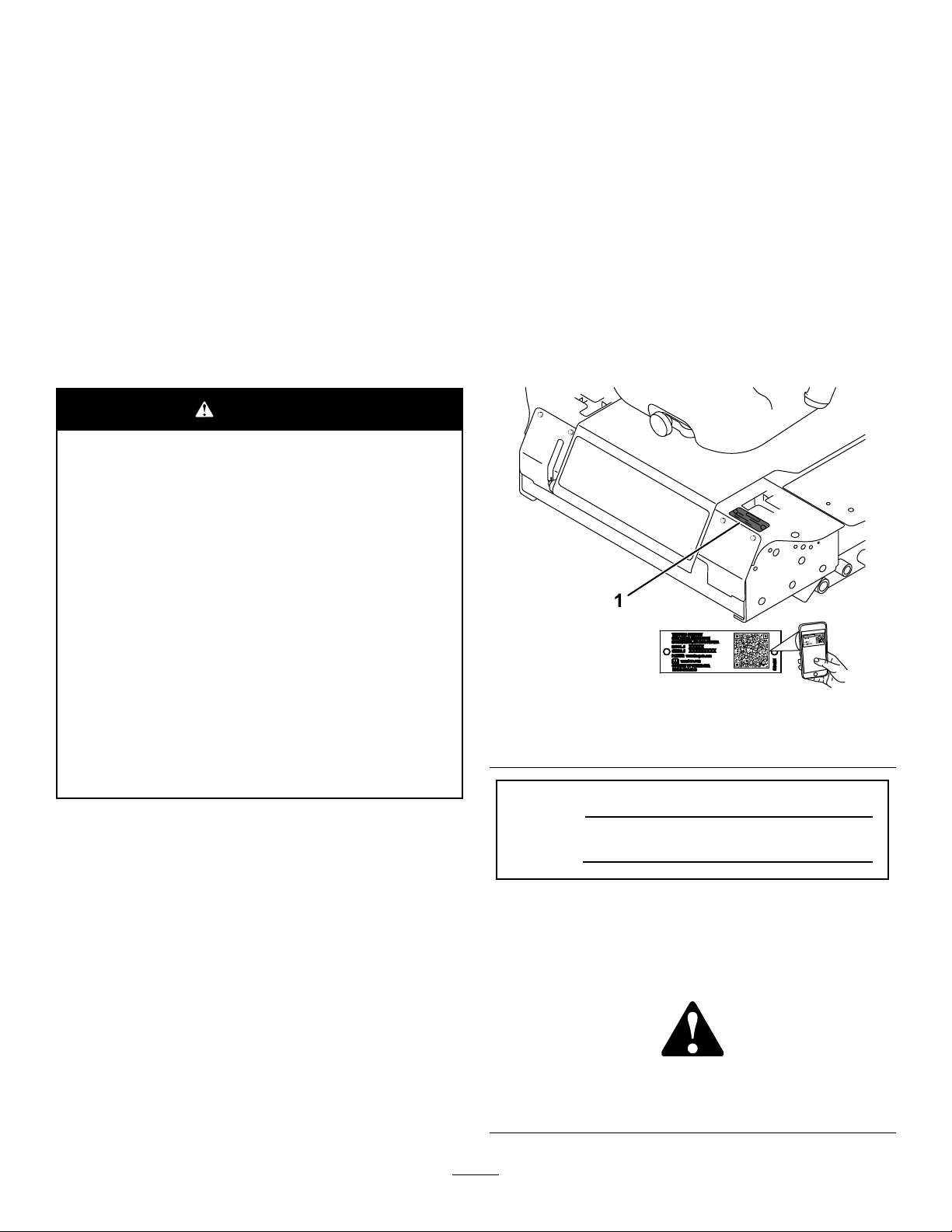
decal107-1866
107-1866
Note:Thismachinecomplieswiththeindustrystandard
stabilitytestinthestaticlateralandlongitudinaltestswiththe
maximumrecommendedslopeindicatedonthedecal.Reviewthe
instructionsforoperatingthemachineonslopesintheOperator’s
Manualaswellastheconditionsinwhichyouwouldoperatethe
machinetodeterminewhetheryoucanoperatethemachineinthe
conditionsonthatdayandatthatsite.Changesintheterraincan
resultinachangeinslopeoperationforthemachine.Ifpossible,
keepthecuttingunitsloweredtothegroundwhileoperatingthe
machineonslopes.Raisingthecuttingunitswhileoperatingon
slopescancausethemachinetobecomeunstable.
1.Sliding/lossofcontrolhazard;tippinghazard,drop-offs—do
notturnathighspeeds;turnatlowspeeds;donotuseon
slopesnearopenwater;donotuseonslopesgreaterthan
15°;stayawayfromdrop-offs.
2.Warning—iftherollbarislowered,donotweartheseatbelt;
iftherollbarisraised,weartheseatbelt.
3.Warning—donotusedualrampswhenloadingontoa
trailer;use1rampwideenoughforthemachine;usea
rampwithaslopelessthan15°.
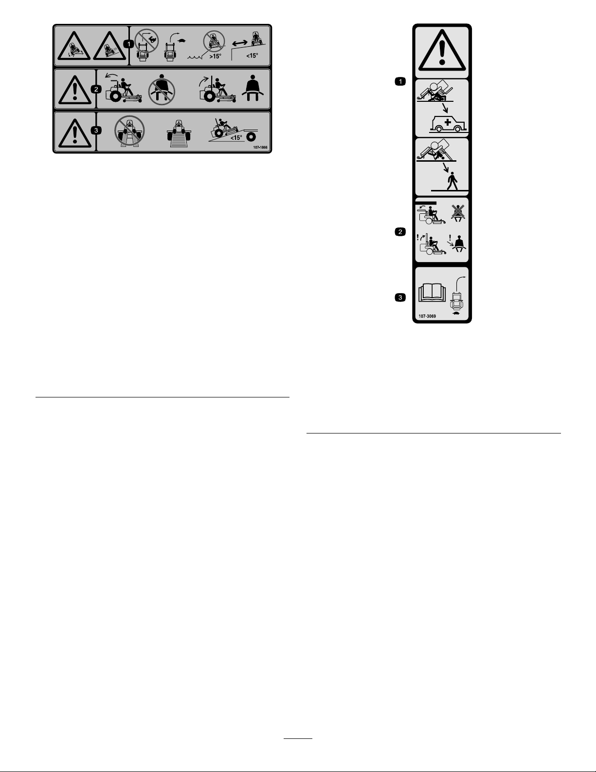
decal107-3069
107-3069
1.Warning–thereisnorolloverprotectionwhentherollbaris
down.
2.T oavoidinjuryordeathfromarolloveraccident,keepthe
rollbarintheraisedandlockedpositionandweartheseat
belt.Lowertherollbaronlywhenabsolutelynecessary;do
notweartheseatbeltwhentherollbarisdown.
3.ReadtheOperator'sManual;driveslowlyandcarefully.
7
Page 8

110-9796
1.ReadtheOperator'sManualforinformationonfuses.
decal110-9796
110-8253
1.PTO–Off4.Continuous-variable
2.PTO—On5.Slow
3.Fast
110-8254
1.Engine–Stop3.Engine—Start
2.Engine—Run
decal110-8253
decal133-5618
133-5618
setting
decal110-8254
8
Page 9

decal110-8252
110-8252
1.ReadtheOperator'sManual.
3.Hydraulicoil5.Enginecoolant
2.Parkingbrake4.Fuel6.Engineoil
110-9781
1.Warning—readtheOperator'sManual.
2.Poisonhazard;causticliquid/chemicalburnhazard—keepchildrenawayfromthebattery.
3.Warning—donottouchthehotsurface.
4.Cutting/dismembermenthazard,fan;entanglementhazard,belt—stayawayfrommovingparts.
5.Hydraulicuidunderpressurehazard;highpressuresprayhazard;highpressureuidhazard,injectionintothebody—wear
handandskinprotection.
decal110-9781
9
Page 10
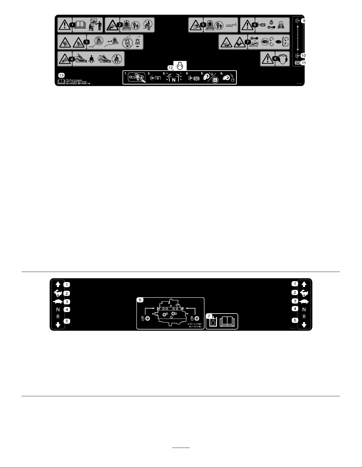
120-9195
Note:Thismachinecomplieswiththeindustrystandardstabilitytestinthestaticlateralandlongitudinaltestswiththemaximum
recommendedslopeindicatedonthedecal.ReviewtheinstructionsforoperatingthemachineonslopesintheOperator’sManualas
wellastheconditionsinwhichyouwouldoperatethemachinetodeterminewhetheryoucanoperatethemachineintheconditions
onthatdayandatthatsite.Changesintheterraincanresultinachangeinslopeoperationforthemachine.Ifpossible,keepthe
cuttingunitsloweredtothegroundwhileoperatingthemachineonslopes.Raisingthecuttingunitswhileoperatingonslopescan
causethemachinetobecomeunstable.
decal120-9195
1.Warning—readtheOperator’sManual;donotoperatethe
machineunlessyouaretrained.
2.Cutting/dismembermenthazard,mowerblade—keep
bystandersaway;donotcarrypassengersonthemachine.
3.Sliding/lossofcontrolhazard;tippinghazard,drop-offs—do
notmowneardrop-offs;keepawayfromdrop-offs;donotturn
athighspeeds;turnatlowspeeds.
4.Tippinghazard—weartheseatbeltwhenarollbarisinplace;
donotweartheseatbeltwhentherollbarislowered.
5.Thrownobjecthazard—keepbystandersaway;lowerthe
deectorbeforeusingthemachine.
6.Warning—engagetheparkingbrake,shutofftheengine,and
removethekeybeforeleavingthemachine.
7.Cutting/dismembermenthazardofhandsorfeet,mower
blade—removethekeyandreadtheOperator’sManual
beforeperformingmaintenance;stayawayfrommovingparts;
keepallguardsandshieldsinplace.
8.Warning—wearhearingprotection.
9.Disengage
10.Engage
11.Parkingbrake
12.Starttheengine—Cleangrassanddebrisfromthemower
beltandpulleys,disengagethePTO,setthedriveinneutral,
engagetheparkingbrake,turnthekeytopoweronthe
mower,andturnthekeyfullytostarttheengine.
13.ReadtheOperator’sManual.
120-9196
1.Forward
3.Slow
2.Fast4.Neutral6.T owvalvelocation;torque
5.Reverse
thetowvalvesto5.65to
7.91N∙m(50to70in-lb).
10
decal120-9196
7.ReadtheOperator's
Manualformore
informationonthehydraulic
uid.
Page 11
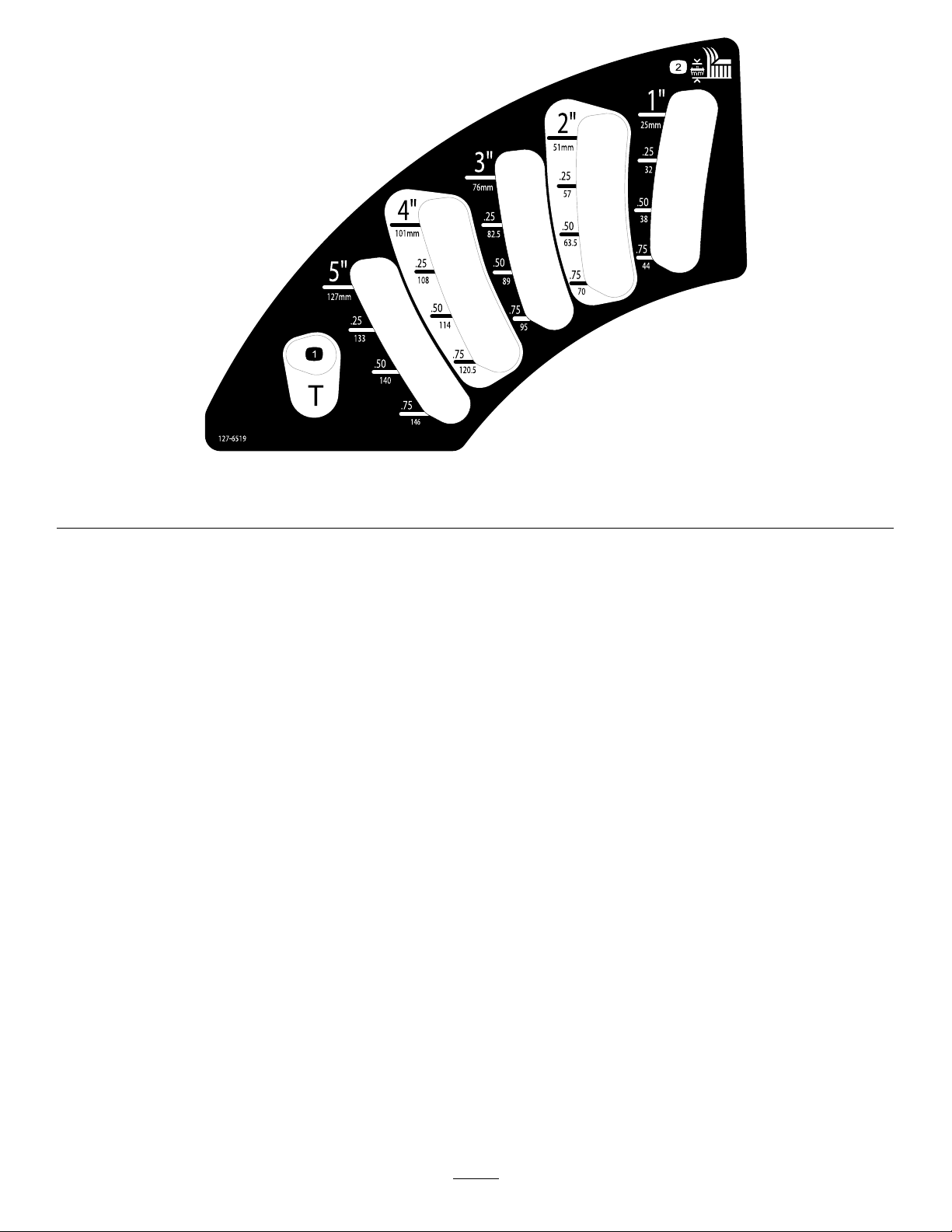
decal127-6519
127-6519
1.Transportposition
2.Heightofcut
11
Page 12

Setup
LooseParts
Usethechartbelowtoverifythatallpartshavebeenshipped.
ProcedureDescription
1
2
3
4
5
6
7
MediaandAdditionalParts
Description
Operator'sManual
Nopartsrequired
CuttingunitInstallationInstructions
Nopartsrequired
Nopartsrequired
Nopartsrequired
Nopartsrequired
Production-yeardecal1
Qty.
1
Reviewitbeforeoperatingthemachine.
Qty.
–
1Installthecuttingunit.
–
–
–
–
RaisetheROPS.
Adjusttheleft,frontcasterwheel.
Checkthetirepressure.
Installweights.
Checkthehydraulicuid,engineoil,
andcoolantlevels.
Installthedecal(CEMachinesOnly).
Use
Use
Engineowner'smanual1
Ignitionkeys2
1
RaisingtheRollBar
NoPartsRequired
Procedure
Raisetherollbar;refertoAdjustingtheRollBar(page
21).
Useittoreferenceengineinformation.
Starttheengine.
2
InstallingtheCuttingUnit
Partsneededforthisprocedure:
1
CuttingunitInstallationInstructions
Procedure
InstallthecuttingunitusingtheInstallationInstructions
forthatcuttingunit.
12
Page 13

3
AdjustingtheLeft,Front
CasterWheel
NoPartsRequired
Procedure
Adjusttheleft,frontcasterwheeltotheoutside
positionfor72-inchcuttingunitsandtotheinside
positionfor60-inchand62-inchcuttingunits.
4
CheckingtheTirePressure
NoPartsRequired
Procedure
Checkthetirepressure;refertoCheckingtheTire
Pressure(page43).
Important:Maintainpressureinalltiresto
ensureagoodquality-of-cutandpropermachine
performance.Donotunderinatethetires.
13
Page 14

5
InstallingWeights(forCECompliance)
NoPartsRequired
Procedure
Machineswith183cm(72inch)decksinstalledandnootherattachmentsdonotneedaddedweighttomeet
CEstandards.However,youmayneedtopurchaseandinstalladditionalweightdependingonthemowerdeck
size/typeandtheattachmentsthatyouinstallonthemachine.Thefollowingtableliststhevariousattachment
congurationsandtheadditionalfrontweightneededforeachmodel:
AttachmentConguration
Groundsmaster7200/7210
TractionUnitwithnoAdded
Attachments
Groundsmaster7200/7210
TractionUnitandHardCanopy
Groundsmaster7200/7210
TractionUnit,HardCanopy,
andRoadLightKit
Groundsmaster7200/7210
TractionUnit,HardCanopy,
RoadLightKit,andJackStand
Groundsmaster7200/7210
TractionUnit,HardCanopy,
andJackStand
Groundsmaster7200/7210
TractionUnit,RoadLightKit,
andJackStand
Groundsmaster7200/7210
TractionUnitandRoadLight
Kit
Groundsmaster7200/7210
TractionUnitandJackStand
WeightRequiredwitha
157.5cm(62inch)Base
Deck(30457)
10kg(22lb)0kg(0lb)0kg(0lb)
34kg(75lb)9.5kg(21lb)15kg(33lb)
32.2kg(71lb)28.5kg(63lb)10kg(22lb)
18kg(40lb)17kg(37lb)10kg(22lb)
14kg(31lb)10kg(22lb)10kg(22lb)
0kg(0lb)0kg(0lb)0kg(0lb)
11.3kg(25lb)0kg(0lb)0kg(0lb)
0kg(0lb)0kg(0lb)0kg(0lb)
WeightRequiredwitha
183cm(72inch)Base
Deck(30353)
WeightRequiredwitha183
cm(72inch)Side-discharge
(30481)
ContactyourauthorizedT orodistributortoobtaintheappropriatekitsandweightsforyourmachine.
14
Page 15
6
CheckingtheFluidLevels
NoPartsRequired
Procedure
1.Checkthehydraulic-uidlevelbeforestarting
theengine,refertoCheckingtheHydraulic
System(page52).
2.Checktheengine-oillevelbeforestartingthe
engine,refertoCheckingtheEngine-OilLevel
(page38).
3.Checkthecoolingsystembeforestartingthe
engine;refertoCheckingtheCoolingSystem
(page44).
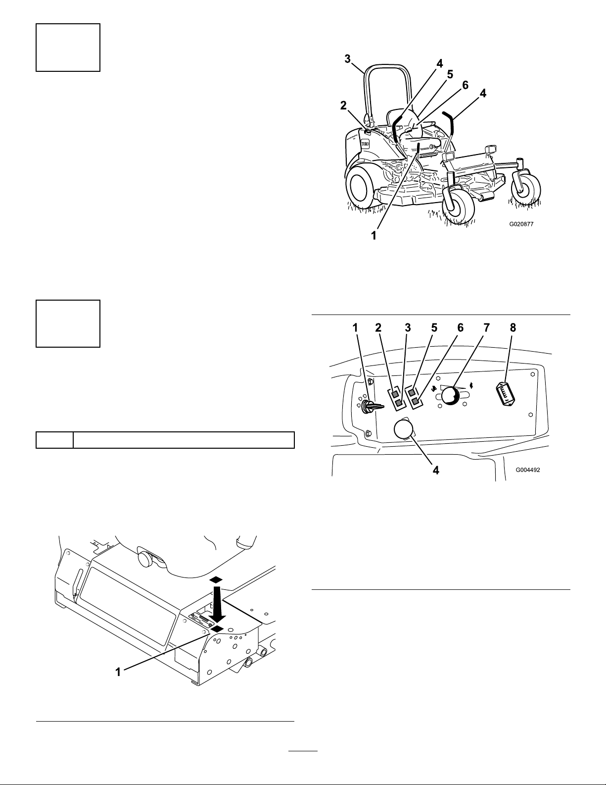
ProductOverview
Figure4
1.Parking-brakelever4.Motion-controllever
2.Fuelcap(bothsides)5.Seat
3.Rollbar
6.Seatbelt
g020877
7
InstallingtheDecal(CE
MachinesOnly)
Partsneededforthisprocedure:
1Production-yeardecal
Procedure
OnmachinesrequiringCEcompliance,installthe
production-yeardecalincludedinthelooseparts
(Figure3).
1.Ignitionswitch
2.Engine-coolant-temperature
warninglight
3.Glow-pluglight
4.Power-takeoff(PTO)
switch
Controls
g004492
Figure5
5.Oil-pressurewarninglight
6.Charge-indicatorlight
7.Throttlelever
8.Hourmeter
Figure3
Becomefamiliarwithallthecontrolsbeforeyoustart
theengineandoperatethemachine(Figure4and
Figure5).
g278244
15
Page 16
Motion-ControlLevers
Glow-Plug-IndicatorLight(Orange
Themotion-controlleverscontroltheforwardand
rearwardmotionsaswellastheturningofthe
machine.RefertoDrivingtheMachine(page27).
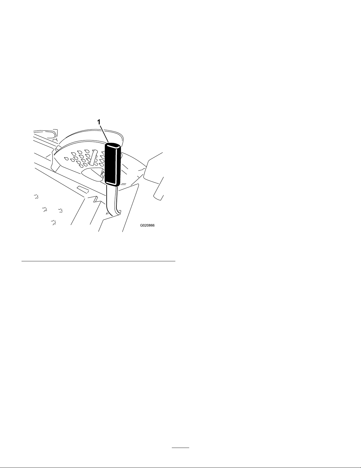
Parking-BrakeLever
Wheneveryoushutofftheengine,engagetheparking
braketopreventaccidentalmovementofthemachine.
Toengagetheparkingbrake,pulltheparking-brake
leverrearwardandup(Figure6).Toreleasethe
parkingbrake,pushtheparking-brakeleverforward
anddown.
Figure6
1.Parking-brakelever
Light)
Theglow-plug-indicatorlight(Figure5)turnsonwhen
youturntheignitionswitchtotheONposition.It
remainsonfor6seconds.Whenthelightturnsoff,
youcanstarttheengine.
HourMeter
Thehourmeterrecordsthenumberofhoursthat
youoperatethemachinewiththekeyswitchinthe
RUNposition.Usethesetimesforschedulingregular
maintenance.
Engine-Coolant-Temperature
WarningLight
Thislightilluminatesandthecuttingbladesstopif
theengine-coolanttemperatureishigh.Ifyoudonot
stopthemachineandthecoolanttemperaturerises
another11°C(20°F),theengineshutsoff.
Important:Ifthemowerdeckshutsdownand
thetemperaturewarninglightison,pushthe
PTOknobdown,drivetoasafe,atarea,move
thethrottlelevertotheSLOWposition,move
themotion-controlleversintotheNEUTRAL-LOCK
position,andengagetheparkingbrake.Idlethe
g020866
engineforseveralminuteswhileitcoolstoasafe
level.Shutofftheengineandcheckthecooling
system;refertoCheckingtheCoolingSystem
(page44).
IgnitionSwitch
Theignitionswitchhas3positions:OFF,ON/PREHEAT,
andST ART.
ThrottleLever
Thethrottlelevercontrolsthespeedoftheengine,
thespeedoftheblades,and,inconjunctionwith
motion-controllevers,thegroundspeedofthe
machine.Movingthethrottleleverforwardtowardthe
FASTpositionincreasestheenginespeed.Moving
itrearwardtowardtheSLOWpositiondecreasesthe
enginespeed.Alwaysrunthemachinewiththe
throttleintheFASTpositionwhencuttinggrass.
Power-Takeoff(PTO)Switch
Thepower-takeoff(PTO)switchstartsandstopsthe
mowerblades.
ChargeIndicator
Thechargeindicatorilluminatesifelectricalcharging
systemisoperatingaboveorbelowthenormal
operatingrange(Figure5).Checkand/orrepairthe
electricalchargingsystem.
Oil-PressureWarningLight
Theoil-pressurewarninglightglowsiftheengine-oil
pressuredropsbelowasafelevel(Figure5).Ifthe
oilpressureislow,shutofftheengineanddetermine
thecause.Repairtheengine-oilsystembeforeyou
starttheengineagain.
16
Page 17
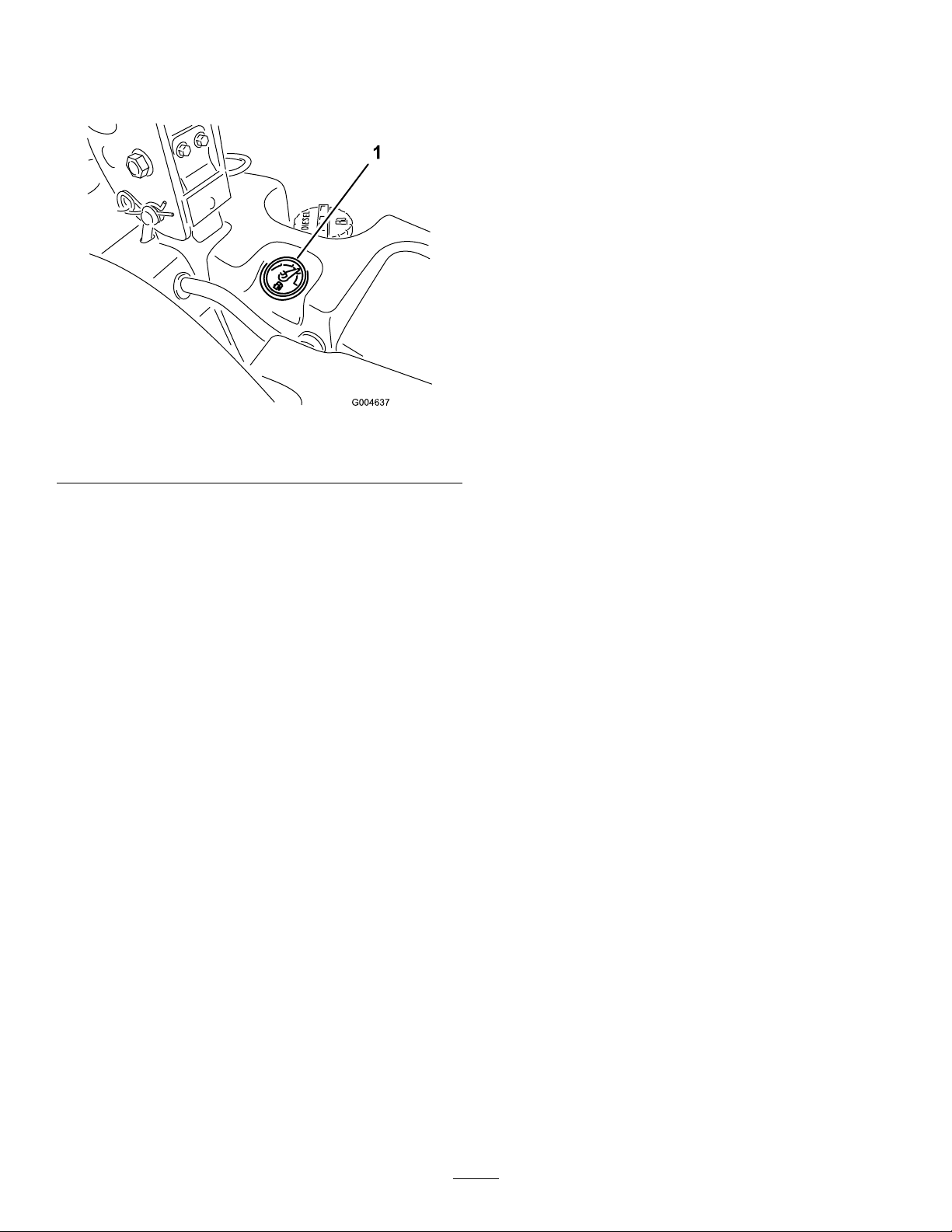
FuelGauge
Thefuelgauge(Figure7)indicatesthequantityoffuel
remaininginthefueltanks.
Figure7
1.Fuelgauge
g004637
17
Page 18

Specications
Figure8
DescriptionFigure8
Heightwithrollbarup
Heightwithrollbardown
Overalllength
Overallwidth
Wheelbase
Wheeltread(tirecentertocenter)rear
reference
C183cm(72inches)
D
F
B
E
A
18
g242892
DimensionorWeight
125cm(49inches)
246cm(97inches)
145cm(57inches)
145cm(57-1/4inches)
114cm(45inches)
Page 19

Groundclearance15cm(6inches)
Weight,with72-inchSide-DischargeCuttingunit(30354or30481)934kg(2,060lb)
Weight,with60-inchSide-DischargeCuttingunit(30456)900kg(1,985lb)
Weight,with72-inchBaseCuttingunit(30353)876kg(1,932lb)
Weight,with62-inchBaseCuttingunit(30457)855kg(1,884lb)
Note:Specicationsanddesignaresubjectto
changewithoutnotice.
Attachments/Accessories
AselectionofToroapprovedattachmentsandaccessoriesisavailableforusewiththemachinetoenhance
andexpanditscapabilities.ContactyourAuthorizedServiceDealerorauthorizedTorodistributororgoto
www.T oro.comforalistofallapprovedattachmentsandaccessories.
Toensureoptimumperformanceandcontinuedsafetycerticationofthemachine,useonlygenuineT oro
replacementpartsandaccessories.Replacementpartsandaccessoriesmadebyothermanufacturerscouldbe
dangerous,andsuchusecouldvoidtheproductwarranty .
Operation
Note:Determinetheleftandrightsidesofthe
machinefromthenormaloperatingposition.
BeforeOperation
BeforeOperationSafety
GeneralSafety
•Neverallowchildrenoruntrainedpeopleto
operateorservicethemachine.Localregulations
mayrestricttheageoftheoperator.Theowner
isresponsiblefortrainingalloperatorsand
mechanics.
•Becomefamiliarwiththesafeoperationofthe
equipment,operatorcontrols,andsafetysigns.
•Shutofftheengine,removethekey(ifequipped),
andwaitforallmovementtostopbeforeyouleave
theoperator’sposition,Allowthemachinetocool
beforeadjusting,servicing,cleaning,orstoringit.
•Knowhowtostopthemachineandshutoffthe
enginequickly.
Replacewornordamagedbladesandboltsinsets
topreservebalance.
•Inspecttheareawhereyouwillusethemachine
andremoveallobjectsthatthemachinecould
throw.
FuelSafety
•Useextremecareinhandlingfuel.Itisammable
anditsvaporsareexplosive.
•Extinguishallcigarettes,cigars,pipes,andother
sourcesofignition.
•Useonlyanapprovedfuelcontainer.
•Donotremovethefuelcaporllthefueltank
whiletheengineisrunningorhot.
•Donotaddordrainfuelinanenclosedspace.
•Donotstorethemachineorfuelcontainerwhere
thereisanopename,spark,orpilotlight,such
asonawaterheaterorotherappliance.
•Ifyouspillfuel,donotattempttostarttheengine;
avoidcreatinganysourceofignitionuntilthefuel
vaporshavedissipated.
•Checkthatoperator-presencecontrols,safety
switches,andguardsareattachedandfunctioning
properly.Donotoperatethemachineunlessthey
arefunctioningproperly.
•Beforemowing,alwaysinspectthemachineto
ensurethattheblades,bladebolts,andcutting
assembliesareingoodworkingcondition.
19
Page 20

AddingFuel
Important:Thepetroleumdieselportionmust
beultra-lowsulfur.
FuelSpecication
•Neverusekeroseneorgasolineinsteadofdiesel
fuel.
•Nevermixkeroseneorusedengineoilwiththe
dieselfuel.
•Neverkeepfuelincontainerswithzincplatingon
theinside.
•Donotusefueladditives.
PetroleumDiesel
Cetanerating:40orhigher
Sulfurcontent:Lowsulfur(<500ppm)orultra-low
sulfur(<15ppm)
FuelTable
Dieselfuelspecication
ASTMD975
No.1-DS15
No.2-DS15
EN590EuropeanUnion
ISO8217DMX
JISK2204GradeNo.2
KSM-2610
Location
USA
International
Japan
Korea
Observethefollowingprecautions:
•Biodieselblendsmaydamagepaintedsurfaces.
•UseB5(biodieselcontentof5%)orlesserblends
incoldweather.
•Monitorseals,hoses,gasketsincontactwithfuel
astheymaydegradeovertime.
•Fuellterpluggingmayoccurforatimeafteryou
converttobiodieselblends.
•Formoreinformationonbiodiesel,contactyour
authorizedT orodistributor.
FuelTankCapacity
43.5L(11.5USgallons)
FillingtheFuelTank
Important:Thefueltanksareconnected,butthe
fueldoesnottransferquicklyfromonetanktothe
other.Itisimportantwhenllingthatyoupark
onalevelsurface.Ifyouparkonahill,youmay
inadvertentlyoverllthetanks.
Important:Donotoverllthefueltanks.
Important:Donotopenthefueltankswhen
parkedonahill.Thefuelcouldspillout.
•Useonlyclean,freshdieselfuelorbiodieselfuels.
•Purchasefuelinquantitiesthatcanbeusedwithin
180daystoensurefuelfreshness.
Usesummer-gradedieselfuel(No.2-D)at
temperaturesabove-7°C(20°F)andwinter-grade
fuel(No.1-DorNo.1-D/2-Dblend)belowthat
temperature.
Note:Useofwinter-gradefuelatlowertemperatures
provideslowerashpointandcoldowcharacteristics
whicheasesstartingandreducesfuellterplugging.
Usingsummer-gradefuelabove-7°C(20°F)
contributestowardlongerfuelpumplifeandincreased
powercomparedtowinter-gradefuel.
UsingBiodiesel
Thismachinecanalsouseabiodiesel-blendedfuelof
uptoB20(20%biodiesel,80%petrodiesel).
Sulfurcontent:Ultra-lowsulfur(<15ppm)
Biodieselfuelspecication:ASTMD6751or
EN14214
Blendedfuelspecication:ASTMD975,EN590,
orJISK2204
g031802
Figure9
Note:Ifpossible,llthefueltanksaftereachuse.
Thisminimizesbuildupofcondensationinsidethe
fueltank.
20
Page 21

CheckingtheEngine-Oil
Level
Beforeyoustarttheengineandusethemachine,
checktheoillevelintheenginecrankcase;referto
CheckingtheEngine-OilLevel(page38).
CheckingtheCooling
System
Beforeyoustarttheengineandusethemachine,
checkthecoolingsystem;refertoCheckingthe
CoolingSystem(page21).
CheckingtheHydraulic
Important:Alwaysusetheseatbeltwhenthe
rollbarisintheraisedandlockedposition.Do
notusetheseatbeltwhentherollbarisinthe
loweredposition.
LoweringtheRollBar
LowertherollbarasshowninFigure11.
Note:Pushthebarforwardtorelievepressureon
thepins.
System
Beforeyoustarttheengineandusethemachine,
checkthehydraulicsystem;refertoCheckingthe
HydraulicSystem(page52).
AdjustingtheRollBar
WARNING
Toavoidinjuryordeathfromrollover,keep
therollbarintheraisedlockedpositionand
usetheseatbelt.
Ensurethattheseatissecuredwiththeseat
latch.
WARNING
Thereisnorolloverprotectionwhentheroll
barisinthedownposition.
•Donotoperatethemachineonuneven
groundoronahillsidewiththerollbarin
thedownposition.
g031636
•Lowertherollbaronlywhenabsolutely
necessary.
•Donotweartheseatbeltwhentherollbar
isinthedownposition.
•Driveslowlyandcarefully .
•Raisetherollbarassoonasclearance
permits.
•Checkcarefullyforoverheadclearances
(i.e.,branches,doorways,electricalwires)
beforedrivingunderanyobjectsanddo
notcontactthem.
g031635
Figure10
Note:Securetherollbarsothatitdoesnotdamage
thehood.
21
Page 22

RaisingtheRollBar
RaisetherollbarasshowninFigure10.
UsingtheSafety-Interlock
System
CAUTION
Ifthesafety-interlockswitchesare
disconnectedordamaged,themachinecould
operateunexpectedly,causingpersonal
g031624
injury.
•Donottamperwiththeinterlockswitches.
•Checktheoperationoftheinterlock
switchesdailyandreplaceanydamaged
switchesbeforeoperatingthemachine.
Understandingthe
Safety-InterlockSystem
Thesafety-interlocksystempreventstheenginefrom
startingunless:
•Youaresittingontheseatortheparkingbrake
isengaged.
•Thepowertakeoff(PTO)isdisengaged.
•Themotion-controlleversareintheNEUTRAL-LOCK
position.
•Theenginetemperatureisbelowthemaximum
operatingtemperature.
Figure11
Important:Alwaysusetheseatbeltwhenthe
rollbarisintheraisedandlockedposition.Do
notusetheseatbeltwhentherollbarisinthe
loweredposition.
Thesafety-interlocksystemalsoshutsoffthe
enginewhenyoumovethetractioncontrolsfrom
theNEUTRAL-LOCKpositionwiththeparkingbrake
engaged.IfyourisefromtheseatwhenthePTO
isengaged,thereisa1-seconddelayandthenthe
engineshutsoff.
g031631
TestingtheSafety-Interlock
System
ServiceInterval:Beforeeachuseordaily
Testthesafety-interlocksystembeforeyouusethe
machineeachtime.Ifthesafetysystemdoesnot
operateasdescribedbelow,haveanAuthorized
ServiceDealerrepairthesafetysystemimmediately .
1.Sitontheseat,engagetheparkingbrake,and
movethePTOtotheONposition.Trystarting
theengine;theengineshouldnotcrank.
2.Sitontheseat,engagetheparkingbrake,
andmovethePTOtotheOFFposition.
Moveeithermotion-controlleveroutofthe
NEUTRAL-LOCKposition.Trystartingtheengine;
theengineshouldnotcrank.Repeatforother
motion-controllever.
3.Sitontheseat,engagetheparkingbrake,move
thePTOswitchtotheOFFposition,andmove
themotion-controlleverstotheNEUTRAL-LOCK
22
Page 23

position.Starttheengine.Whiletheengineis
running,releasetheparkingbrake,engagethe
PTO,andriseslightlyfromtheseat;theengine
shouldshutoffwithin2seconds.
4.Withoutanoperatorontheseat,engagethe
parkingbrake,movethePTOswitchtotheOFF
position,andmovethemotion-controlleversto
theNEUTRAL-LOCKposition.Starttheengine.
Whiletheengineisrunning,centereithermotion
control;theengineshouldshutoffwithin2
seconds.Repeatfortheothermotion-control
lever.
5.Withoutanoperatorontheseat,disengagethe
parkingbrake,movethePTOswitchtotheOFF
position,andmovethemotion-controllevers
totheNEUTRAL-LOCKposition.Trystartingthe
engine;theengineshouldnotcrank.
UsingtheSCMtoDiagnose
SystemProblems
Themachineisequippedwithastandardcontrol
module(SCM)monitoringsystemthattracksthe
functionofvariouskeysystems.TheSCMislocated
undertherightcontrolpanel.Accessitthroughthe
sidepanelcover(Figure12).Toopenthesidepanel
cover,releasethe2latchesandpulloutonit.
g004927
Figure13
1.Hightemperatureshutdown—theenginetemperaturehas
exceededsafelevelsandtheenginehasbeenshutdown.
Checkthecoolingsystem.
2.Hightemperaturewarning—theenginetemperatureis
approachingunsafelevelsandthecuttingunithasbeen
shutdown.Checkthecoolingsystem.
3.Operatorisintheseat.
4.ThePTOison.
5.Theparkingbrakeisnotengaged.
6.Controlsareinneutral.
7.TheSCMisreceivingpowerandisoperational.
PositioningtheSeat
Figure12
1.Sidepanelcover
2.Latches
OnthefaceoftheSCMare11LEDsthatilluminate
toindicatevarioussystemconditions.Youcanuse7
oftheselightsforsystemdiagnosis.RefertoFigure
13foradescriptionofwhateachlightmeans.For
detailsonusingtherestoftheSCMfunctions,referto
theServiceManual,availablethroughyourauthorized
Torodistributor.
Theseatmovesforwardandbackward.Positionthe
seatwhereyouhavethebestcontrolofthemachine
andaremostcomfortable.
Toadjust,movetheleversidewaystounlocktheseat
(Figure14).
g004495
Figure14
g008962
23
Page 24

ChangingtheSeat
Suspension
DuringOperation
Theseatisadjustabletoprovideasmoothand
comfortableride.Positiontheseatwhereyouare
mostcomfortable.
Toadjustit,turntheknobinfronteitherdirectionto
providethebestcomfort(Figure15).
Figure15
1.Seat-suspensionknob
UnlatchingtheSeat
Toaccessthehydraulicandothersystemsunderthe
seat,unlatchtheseatandswingitforward.
1.Usetheseatpositionadjustmentlevertoslide
theseatallthewayforward.
2.Pulltheseatlatchforwardandliftuptounlatch
theseat(Figure16).
DuringOperationSafety
GeneralSafety
•Theowner/operatorcanpreventandisresponsible
foraccidentsthatmaycausepersonalinjuryor
propertydamage.
•Wearappropriateclothing,includingeye
protection;longpants;substantial,slip-resistant
footwear;andhearingprotection.Tiebacklong
hairanddonotwearlooseclothingorloose
jewelry.
•Donotoperatethemachinewhileill,tired,or
undertheinuenceofalcoholordrugs.
•Useyourfullattentionwhileoperatingthe
machine.Donotengageinanyactivitythat
causesdistractions;otherwise,injuryorproperty
g019768
damagemayoccur.
•Beforeyoustarttheengine,ensurethatalldrives
areinneutral,theparkingbrakeisengaged,and
youareintheoperatingposition.
•Donotcarrypassengersonthemachineandkeep
bystandersandchildrenoutoftheoperatingarea.
•Operatethemachineonlyingoodvisibilitytoavoid
holesorhiddenhazards.
•Avoidmowingonwetgrass.Reducedtraction
couldcausethemachinetoslide.
•Keepyourhandsandfeetawayfromrotating
parts.Keepclearofthedischargeopening.
•Lookbehindanddownbeforebackinguptobe
sureofaclearpath.
1.Seatlatch
Figure16
•Usecarewhenapproachingblindcorners,shrubs,
trees,orotherobjectsthatmayobscureyour
vision.
•Stopthebladeswheneveryouarenotmowing.
•Stopthemachine,removethekey,andwaitfor
allmovingpartstostopbeforeinspectingthe
attachmentafterstrikinganobjectorifthereis
anabnormalvibrationinthemachine.Makeall
necessaryrepairsbeforeresumingoperation.
•Slowdownandusecautionwhenmakingturns
andcrossingroadsandsidewalkswiththe
machine.Alwaysyieldtheright-of-way.
g020871
•Disengagethedrivetothecuttingunit,shut
offtheengine,removethekey,andwaitforall
movingpartstostopbeforeadjustingtheheightof
cut(unlessyoucanadjustitfromtheoperating
position).
24
Page 25

•Operatetheengineonlyinwell-ventilatedareas.
Exhaustgasescontaincarbonmonoxide,which
islethalifinhaled.
•Neverleavearunningmachineunattended.
•Beforeyouleavetheoperator’sposition,dothe
following:
–Parkthemachineonalevelsurface.
–Disengagethepowertakeoffandlowerthe
attachments.
–Engagetheparkingbrake.
–Shutofftheengineandremovethekey(if
equipped).
–Waitforallmovementtostop.
•Operatethemachineonlyingoodvisibilityand
appropriateweatherconditions.Donotoperate
themachinewhenthereistheriskoflightning.
•Donotusethemachineasatowingvehicle.
•Useaccessories,attachments,andreplacement
partsapprovedbyT oroonly .
RolloverProtectionSystem
(ROPS)Safety
SlopeSafety
•Slopesareamajorfactorrelatedtolossofcontrol
androlloveraccidents,whichcanresultinsevere
injuryordeath.Y ouareresponsibleforsafeslope
operation.Operatingthemachineonanyslope
requiresextracaution.
•Evaluatethesiteconditionstodetermineifthe
slopeissafeformachineoperation,including
surveyingthesite.Alwaysusecommonsense
andgoodjudgmentwhenperformingthissurvey .
•Reviewtheslopeinstructionslistedbelowfor
operatingthemachineonslopesandtodetermine
whetheryoucanoperatethemachineinthe
conditionsonthatdayandatthatsite.Changes
intheterraincanresultinachangeinslope
operationforthemachine.
•Avoidstarting,stopping,orturningthemachineon
slopes.Avoidmakingsuddenchangesinspeedor
direction.Maketurnsslowlyandgradually.
•Donotoperateamachineunderanyconditions
wheretraction,steering,orstabilityisinquestion.
•Removeormarkobstructionssuchasditches,
holes,ruts,bumps,rocks,orotherhiddenhazards.
Tallgrasscanhideobstructions.Uneventerrain
couldoverturnthemachine.
•DonotremoveanyoftheROPScomponentsfrom
themachine.
•Ensurethattheseatbeltisattachedandthatyou
canreleaseitquicklyinanemergency.
•Checkcarefullyforoverheadobstructionsanddo
notcontactthem.
•KeeptheROPSinsafeoperatingconditionby
thoroughlyinspectingitperiodicallyfordamage
andkeepingallthemountingfastenerstight.
•ReplacedamagedROPScomponents.Donot
repairoralterthem.
•Alwaysusetheseatbeltwiththerollbarinthe
raisedposition.
•TheROPSisanintegralsafetydevice.Keepa
foldingrollbarintheraisedandlockedposition,
andusetheseatbeltwhenoperatingthemachine
withtherollbarintheraisedposition.
•Lowerafoldingrollbartemporarilyonlywhen
necessary.Donotweartheseatbeltwhenthe
rollbarisfoldeddown.
•Beawarethatthereisnorolloverprotectionwhen
afoldedrollbarisinthedownposition.
•Beawarethatoperatingthemachineonwet
grass,acrossslopes,ordownhillmaycausethe
machinetolosetraction.Lossoftractiontothe
drivewheelsmayresultinslidingandalossof
brakingandsteering.
•Useextremecautionwhenoperatingthemachine
neardrop-offs,ditches,embankments,water
hazards,orotherhazards.Themachinecould
suddenlyrolloverifawheelgoesovertheedge
ortheedgecavesin.Establishasafetyarea
betweenthemachineandanyhazard.
•Identifyhazardsatthebaseoftheslope.
Iftherearehazards,mowtheslopewitha
pedestrian-controlledmachine.
•Ifpossible,keepthecuttingunit(s)loweredtothe
groundwhileoperatingonslopes.Raisingthe
cuttingunit(s)whileoperatingonslopescancause
themachinetobecomeunstable.
•Useextremecautionwithgrass-collectionsystems
orotherattachments.Thesecanchangethe
stabilityofthemachineandcausealossofcontrol.
•Checktheareathatyouwillbemowingandnever
folddownafoldingrollbarinareaswherethere
areslopes,drop-offs,orwater.
25
Page 26

OperatingtheParking
StartingtheEngine
Brake
Alwaysengagetheparkingbrakewhenyoustopthe
machineorleaveitunattended.
EngagingtheParkingBrake
WARNING
Theparkingbrakemaynotholdthemachine
parkedonaslopeandcouldcausepersonal
injuryorpropertydamage.
Donotparkthemachineonslopesunlessthe
wheelsarechockedorblocked.
Note:Theglowpluglightilluminatesfor6seconds
whenyouturntheignitionkeytotheRUNposition.
TurntheignitiontotheST ARTpositionafterthelight
goesout.
Important:Usestartingcyclesofnomorethan
15secondsperminutetoavoidoverheatingthe
startermotor.
Important:Operatethemachinewiththethrottle
leverintheSLOWpositioninboththeforward
andreversedirectionsfor1to2minutesafter
changingtheengineoil,overhaulingeitherthe
engine,transmission,orwheelmotor,andwhen
youstarttheengineforthersttime.Operatethe
liftleverandPTOlevertoensurethattheyoperate
properly.Shuttheengineoff,checkuidlevels,
andcheckforoilleaks,looseparts,andanyother
noticeablemalfunctions.
Figure17
ReleasingtheParkingBrake
Figure18
g027914
g027915
g191137
Figure19
Note:LeavethethrottlemidwaybetweentheSLOW
andFASTpositionsuntiltheengineandhydraulic
systemwarmup.
26
Page 27

DrivingtheMachine
Thethrottlecontrolregulatestheenginespeedas
measuredinrpm(revolutionsperminute).Place
thethrottlecontrolintheFASTpositionforbest
performance.AlwaysoperateintheFASTthrottle
positionwhenrunningpoweredattachments.
CAUTION
Themachinecanturnveryrapidly.Youmay
losecontrolofitandcausepersonalinjuryor
damagethemachine.
•Usecautionwhenmakingturns.
•Slowthemachinedownbeforemaking
sharpturns.
1.Releasetheparkingbrake.
Note:Theengineshutsoffifyoumovethe
motion-controlleversoutoftheNEUTRAL-LOCK
positionwiththeparkingbrakeengaged.
2.Movetheleverstothecenter,unlockedposition.
3.Drivethemachineasfollows:
•Tomovestraightforward,slowlypushthe
motion-controlleversforward(Figure20).
•Tomovestraightrearward,slowlypullthe
motion-controlleversrearward(Figure20).
•Toturn,slowthemachinebypullingbackon
bothleversandthenpushforwardonthe
leverontheoppositesidefromwhichyou
wanttoturn(Figure20).
•Tostop,pullthemotion-controlleverstothe
NEUTRALposition.
Note:Thefartheryoumovethemotion-control
leversineitherdirection,thefasterthemachine
movesinthatdirection.
Figure20
1.Motion-control
lever—NEUTRAL-LOCK
position
2.Center,unlockedposition5.Frontofthemachine
3.Forward
4.Backward
g004532
27
Page 28

ShuttingOfftheEngine
OperatingtheMower
CAUTION
Childrenorbystandersmaybeinjuredifthey
attempttomoveoroperatethetractorwhile
itisunattended.
Alwaysremovetheignitionkeyandengage
theparkingbrakewhenleavingthemachine
unattended,evenifjustforafewminutes.
UsingtheDeck-LiftSwitch
Thedeck-liftswitchraisesandlowersthecuttingunit
(Figure22).Theenginemustberunningforyouto
usethislever.
Figure21
g244208
g020873
Figure22
1.Deck-liftswitch
•Tolowerthecuttingunit,pushthedeck-liftswitch
down(Figure22).
Important:Whenyoulowerthecuttingunit,
itsetsinaoat/idleposition.
•Toraisethemoverdeck,pushthedeck-liftswitch
up(Figure22).
Important:Donotcontinuetoholdtheswitch
upordownafterthemowerhasfullyraisedor
lowered.Doingsodamagesthehydraulicsystem.
28
Page 29

EngagingthePowerTakeoff(PTO)
Thepower-takeoff(PTO)switchstartsandstopsthe
mowerbladesandsomepoweredattachments.
Note:Iftheengineiscold,allowtheenginetowarm
up5to10minutesbeforeengagingthePTO.
Figure23
DisengagingthePTO
locatedinthesecondrow.Thisdoesnotadd
6mm(1/4inch)tothe15.8cm(6inch)position.
g243799
Figure24
AdjustingtheHeightofCut
Youcanadjusttheheightofcutfrom2.5to15.8cm
(1to6inches)in6mm(1/4inch)incrementsby
relocatingthestoppinintodifferentholelocations.
1.Withtheenginerunning,pushthedeck-lift
switchupuntilthecuttingunitisfullyraisedand
releasetheswitchimmediately(Figure22).
2.Rotatethestoppinuntiltherollpininitlinesup
withtheslotsintheholesintheheight-of-cut
bracketandremoveit(Figure25).
3.Selectaholeintheheight-of-cutbracket
correspondingtotheheightofcutdesired,insert
thepin,androtateitdowntolockitinplace
(Figure25).
Note:Thereare4rowsofholepositions
(Figure25).Thetoprowgivesyoutheheightof
cutlistedabovethepin.Thesecondrowdown
givesyoutheheightlistedplus6mm(1/4inch).
Thethirdrowdowngivesyoutheheightlisted
plus12mm(1/2inch).Thebottomrowgivesyou
theheightlistedplus18mm(3/4inch).Forthe
15.8cm(6inch)position,thereisonly1hole,
g020870
Figure25
1.Stoppin2.Height-of-cutstop
g009174
4.Adjusttheanti-scalprollersandskidsas
required.
OperatingTips
FastThrottleSetting/Ground
Speed
Tomaintainenoughpowerforthemachineanddeck
whilemowing,operatetheengineattheFASTthrottle
positionandadjustyourgroundspeedforconditions.
Decreasethegroundspeedastheloadonthecutting
bladesincrease;increasethegroundspeedasthe
loadonthebladesdecrease.
AlternatingtheMowingDirection
Alternateyourmowingdirectiontoavoidmaking
rutsintheturf,whichcanappearovertime.This
alsohelpstodisperseclippings,whichenhances
decompositionandfertilization.
CuttingSpeed
Toimprovecutquality,useaslowergroundspeed
incertainconditions.
29
Page 30

AvoidingaLowCut
Ifthemachinecuttingwidthiswiderthanthemachine
thatyoupreviouslyused,raisethecuttingheightto
ensurethatuneventurfisnotcuttooshort.
SelecttheProperHeight-of-Cut
SettingtoSuitConditions
AfterOperation
GeneralSafety
•Shutofftheengine,removethekey(ifequipped),
andwaitforallmovementtostopbeforeyouleave
theoperator’sposition,Allowthemachinetocool
beforeadjusting,servicing,cleaning,orstoringit.
Removeapproximately25mm(1inch)orno
morethan1/3ofthegrassbladewhencutting.In
exceptionallylushanddensegrass,youmayneed
toslowdowntheforwardspeedand/orraisethe
height-of-cuttothenexthighersetting.
Important:Ifyouarecuttingmorethan1/3ofthe
grassblade,oraremowinginsparselonggrass
ordryconditions,usetheatsailofthebladesto
reduceair-bornechaff,debris,andstrainonthe
deck-drivecomponents.
CuttingLongGrass
Ifyouallowthegrasstogrowslightlylongerthan
normal,orifthegrasscontainsahighdegreeof
moisture,raisethecuttingheighttoahighersetting
andcutthegrassatthissetting.Thencutthegrass
againusingthelower,normalsetting.
KeepingtheMowerClean
Cleanclippingsanddirtfromtheundersideofthe
moweraftereachuse.Ifgrassanddirtbuildup
insidethemower,cuttingqualityeventuallybecomes
unsatisfactory.
Toreducetheriskofrehazard,keeptheengine,
mufer,batterycompartment,parkingbrake,cutting
units,andfuelstoragecompartmentfreeofgrass,
leaves,orexcessivegrease.Cleanupanyspilledoil
orfuel.
•Cleangrassanddebrisfromthecuttingunits,
mufers,andenginecompartmenttohelpprevent
res.Cleanupoilorfuelspills.
•Ifthecuttingunitsareinthetransportposition,use
thepositivemechanicallock(ifavailable)before
youleavethemachineunattended.
•Allowtheenginetocoolbeforestoringthemachine
inanyenclosure.
•Removethekeyandshutoffthefuel(ifequipped)
beforestoringorhaulingthemachine.
•Neverstorethemachineorfuelcontainerwhere
thereisanopename,spark,orpilotlight,such
asonawaterheateroronotherappliances.
•Maintainandcleantheseatbelt(s)asnecessary
PushingtheMachine
Inanemergency ,youcanmovethemachineavery
shortdistancebyactuatingthebypassvalvesinthe
hydraulicpumpandpushingthemachine.
Important:Alwayspushthemachinebyhand
andneveralongdistance.Nevertowthemachine,
becausedamagetothehydraulicsystemmay
occur.
Important:Thebypassvalvesmustbeopen
wheneveryoupushortowthemachine.Close
thevalvesonceyouhavepushedortowedthe
machinetothedesiredlocation.
MaintainingtheBlades
•Maintainsharpbladesthroughoutthecutting
season.Sharpbladescreateacleancutwithout
tearingorshreddingthegrassblades.Tearing
andshreddingcausesgrasstoturnbrownatthe
edges,whichslowsgrowthandincreasesthe
chanceofdisease.
•Checkthebladesdailyforsharpnessandfor
anywearordamage.Sharpenthebladesas
necessary.
•Ifabladeisdamagedorworn,replaceit
immediatelywithagenuineT ororeplacement
blade.RefertothecuttingunitOperator’sManual
forinstructionstoreplacetheblade.
1.Lifttheseat;refertoUnlatchingtheSeat(page
24)
2.Locatethebypassvalves(Figure26)androtate
eachbypassvalvecounterclockwise1turn.
Note:Thisallowshydraulicuidtobypassthe
pump,enablingthewheelstoturn.
Important:Donotrotatethebypassvalves
morethan1turn.Thispreventsvalvesfrom
comingoutofthebodyandcausinguidto
runout.
30
Page 31

Figure26
HaulingtheMachine
Useaheavy-dutytrailerortrucktohaulthemachine.
Ensurethatthetrailerortruckhasallthenecessary
brakes,lighting,andmarkingasrequiredbylaw.
Pleasecarefullyreadallthesafetyinstructions.
Knowingthisinformationcouldhelpyou,yourfamily,
pets,orbystandersavoidinjury .
WARNING
Drivingonthestreetorroadwaywithout
turnsignals,lights,reectivemarkings,ora
slow-moving-vehicleemblemisdangerous
andcanleadtoaccidentscausingpersonal
injury.
Donotdrivethemachineonapublicstreet
g004644
orroadway.
1.Rightbypassvalve
3.Ensurethattheparkingbrakeisdisengagedand
pushthemachinetothedesiredlocation.
4.Closethevalvesbyrotatingeachvalve1
clockwiseturn(Figure26).
2.Leftbypassvalve
Note:Donotovertightenthevalves.
5.Torquethevalvestoapproximately8N∙m(71
in-lb).
Important:Ensurethatthebypassvalves
areclosedbeforeyoustarttheengine.
Runningtheenginewithopenbypassvalves
causesthetransmissiontooverheat.
1.Ifyouareusingatrailer,connectittothetowing
vehicle,andconnectthesafetychains.
2.Ifapplicable,connectthetrailerbrakes.
3.Loadthemachineontothetrailerortruck;refer
toLoadingtheMachine(page32).
4.Shutofftheengine,removethekey,engagethe
parkingbrake,andclosethefuelvalve.
5.Usethetie-downloopsonthemachineto
securelyfastenittothetrailerortruckwith
straps,chains,cable,orropes(Figure27).
1.Tractionunittie-downloops
31
g191318
Figure27
Page 32

LoadingtheMachine
Useextremecautionwhenloadingorunloading
machinesontoatraileroratruck.Useafull-width
rampthatiswiderthanthemachineforthisprocedure.
Drivethemachineuprampsinreverseanddriveit
downrampsinaforwarddirection(Figure28).
Figure28
g027995
1.Drivethemachineupthe
rampinreverse.
2.Drivethemachineforward
downtheramp.
Important:Donotusenarrowindividualramps
foreachsideofthemachine.
WARNING
Loadingthemachineontoatrailerortruck
increasesthepossibilityoftipoverandcould
causeseriousinjuryordeath.
•Useextremecautionwhenoperatinga
machineonaramp.
•Whenloadingorunloadingthemachine,
usetheseatbeltandensurethattheroll
barisintheraisedposition.Ensurethat
therollbarcanclearthetopofanenclosed
trailer.
•Useonlyafull-widthramp;donotuse
individualrampsforeachsideofthe
machine.
1.Full-widthrampinstowed
position
2.Sideviewoffull-width
rampinloadingposition
3.Notgreaterthan15°
g027996
Figure29
4.Rampisatleast4times
aslongastheheightof
thetrailerortruckbedto
theground
5.“H”indicatestheheightof
thetrailerortruckbedto
theground.
6.Trailer
•Donotexceeda15°anglebetweenthe
rampandtheground,orbetweentheramp
andthetrailerortruck.
•Ensurethattheramplengthisatleast4
timesaslongastheheightofthetraileror
truckbedtotheground.Thisensuresthat
therampangledoesnotexceed15°onat
ground.
•Drivethemachineuprampsinreverseand
driveitdownrampsinaforwarddirection.
•Whiledrivingthemachineonaramp,avoid
suddenaccelerationordeceleration,as
thiscouldcausealossofcontrolora
tipoversituation.
32
Page 33

Maintenance
Note:Determinetheleftandrightsidesofthemachinefromthenormaloperatingposition.
MaintenanceSafety
•Beforeyouleavetheoperator’sposition,dothe
following:
–Parkthemachineonalevelsurface.
–Disengagethepowertakeoffandlowerthe
attachments.
–Engagetheparkingbrake.
–Shutofftheengineandremovethekey(if
equipped).
–Waitforallmovementtostop.
•Allowmachinecomponentstocoolbefore
performingmaintenance.
•Ifthecuttingunitsareinthetransportposition,use
thepositivemechanicallock(ifequipped)before
youleavethemachineunattended.
RecommendedMaintenanceSchedule(s)
MaintenanceService
Interval
MaintenanceProcedure
•Ifpossible,donotperformmaintenancewhilethe
engineisrunning.Keepawayfrommovingparts.
•Supportthemachinewithjackstandswhenever
youworkunderthemachine.
•Carefullyreleasepressurefromcomponentswith
storedenergy.
•Keepallpartsofthemachineingoodworking
conditionandallhardwaretightened,especially
blade-attachmenthardware.
•Replaceallwornordamageddecals.
•Toensuresafe,optimalperformanceofthe
machine,useonlygenuineTororeplacement
parts.Replacementpartsmadebyother
manufacturerscouldbedangerous,andsuchuse
couldvoidtheproductwarranty.
Aftertherst10hours
Aftertherst50hours
Aftertherst200hours
Beforeeachuseordaily
Every50hours
Every100hours
Every150hours
Every200hours
•Torquetheframe-mountingbolts.
•Torquethewheellugnuts.
•Changethecutting-unitgearboxlubricant.
•Changetheengineoilandlter.
•Changethehydraulicuidandlter.
•Testthesafety-interlocksystem.
•Checktheengineoillevel.
•Checktheenginecoolantlevel.
•Cleantheradiatorwithcompressedair(moreoftenindirtyanddustyconditions).
•Checkthehydraulicuidlevel.
•Cleanthecuttingunitandmachine.
•Cleanthemachine.
•Cleanandmaintaintheseatbelt.
•Greasethebearingandbushinggreasettings(moreoftenindirtyordusty
conditionsandaftereverywashing).
•Checkbatterycableconnections.
•Checkthetirepressure.
•Checkthealternator-belttension.
•Checkthelubricantinthecutting-unitgearbox.
•Changetheengineoilandlter.
•Inspectthecooling-systemhosesandseals.Replacethemifcrackedortorn.
•Torquethewheellugnuts.
33
Page 34

MaintenanceService
Every400hours
Every800hours
Interval
MaintenanceProcedure
•Changethecutting-unitgearboxlubricant.
•Servicetheair-cleanerlter.—servicethelteralsowhentheair-cleanerindicator
showsred;servicetheair-cleanerltermorefrequentlyinextremelydustyordirty
conditions.
•Servicetheaircleaner.
•Replacethefuel-ltercanisterforthewaterseparator.
•Drainwaterorothercontaminantsfromthewaterseparator.
•Inspectthefuellinesandconnections.
•Drainandcleanthefueltank.
•Changethehydraulicuidandlter.
•Inspecttheengine-valveclearance.Refertoyourengineowner’smanual.
Every1,500hours
Beforestorage
Every2years
•Replacemovinghoses.
•Drainandcleanthefueltank.
•Flushandreplacethecooling-systemuid.
Important:Refertoyourengineowner’smanualforadditionalmaintenanceprocedures.
Note:Downloadafreecopyoftheelectricalorhydraulicschematicbyvisitingwww.T oro.comandsearching
foryourmachinefromtheManualslinkonthehomepage.
Important:Thefastenersonthecoversofthismachinearedesignedtoremainonthecoverafter
removal.Loosenallthefastenersoneachcoverafewturnssothatthecoverisloosebutstillattached,
thengobackandloosenthemuntilthecovercomesfree.Thispreventsyoufromaccidentallystripping
theboltsfreeoftheretainers.
34
Page 35

DailyMaintenanceChecklist
Duplicatethispageforroutineuse.
Checkthesafety-interlock
operation.
Checkthegrassdeector
inthedownposition(if
applicable).
Checktheparking-brake
operation.
Checkthefuellevel.
Checkthehydraulicuid
level.
Checktheengine-oillevel.
Checkthecooling-system
uidlevel.
Checkthedrainwater/fuel
separator.
Checktheair-lterrestriction
indicator.
Checktheradiatorand
screenfordebris
Checkforunusualengine
noises.
Checkforunusualoperating
noises.
Checkthehydraulichoses
fordamage
Checkforuidleaks.
Checkthetirepressure.
Checktheinstrument
operation.
Checktheconditionofthe
blades.
Lubricateallgreasettings.
Cleanthemachine
Touchupdamagedpaint.
1.Iftheindicatorshowsred
1
2
3
Fortheweekof: MaintenanceCheckItem
Mon.Tues.Wed.Thurs.Fri.
Sat.Sun.
2.Checkglowplugandinjectornozzlesifyounoticehardstarting,excesssmoke,orroughrunning.
3.Immediatelyaftereverywashing,regardlessoftheintervallisted.
Notationforareasofconcern
Inspectionperformedby:
ItemDate
35
Information
Page 36

CAUTION
Ifyouleavethekeyintheignitionswitch,someonecouldaccidentlystarttheengineand
seriouslyinjureyouorotherbystanders.
Removethekeyfromtheignitionbeforeyoudoanymaintenance.
Lubrication
GreasingtheBearingsand
Bushings
ServiceInterval:Every50hours(moreoftenindirty
ordustyconditionsandafterevery
washing).
Themachinehasgreasettingsthatyoumust
lubricateregularlywithNo.2lithiumgrease.Lubricate
moreoftenindirtyordustyconditionsbecausedirt
cangetintothebearingsandbushingsandcause
acceleratedwear.
1.Wipethegreasettingscleansothatforeign
mattercannotbeforcedintothebearingor
bushing.
2.Pumpgreaseintothettings.
3.Wipeoffexcessgrease.
Note:Improperwash-downprocedurescan
negativelyaffectbearinglife.Donotwashdown
themachinewhenitisstillhotandavoiddirecting
high-pressureorhigh-volumesprayatthebearings
orseals.
3.DisengagethePTO,movethemotion-control
leverstotheNEUTRAL-LOCKposition,and
engagetheparkingbrake.
4.MovethethrottlelevertotheSLOWposition,
shutofftheengine,removethekey ,andwait
forallmovingpartstostopbeforeleavingthe
operatingposition.
5.Liftthefootrest,exposingthetopofthecutting
unit.
6.Removethedipstick/llplugfromthetopofthe
gearboxandmakesurethatthelubricantis
betweenthemarksonthedipstick(Figure30).
ServicingtheCutting-Unit
GearboxLubricant
ThegearboxisdesignedtooperatewithSAE
EP90Wgearlube.Althoughthegearboxcomes
fromthefactorywithlubricant,checkthelevelofthe
lubricantinthecuttingunitbeforeoperatingitandas
recommendedintheDailyMaintenanceChecklist
(page35).
CheckingtheCutting-Unit
GearboxLubricant
ServiceInterval:Every150hours
1.Positionthemachineandcuttingunitonalevel
surface.
2.Lowerthecuttingunittothe2.5cm(1inch)
heightofcut.
g004502
Figure30
1.Fillpluganddipstick
7.Ifthelubricantlevelislow,addenoughlubricant
untilthelevelisbetweenthemarksonthe
dipstick.
Important:Donotoverllthegearbox;
overllingthegearboxmaydamageit.
36
Page 37

ChangingtheCutting-Unit
GearboxLubricant
EngineMaintenance
ServiceInterval:Aftertherst50hours
Every400hours
1.Positionthemachineandcuttingunitonalevel
surface.
2.Lowerthecuttingunittothe2.5cm(1inch)
heightofcut.
3.DisengagethePTO,movethemotion-control
leverstotheNEUTRAL-LOCKposition,and
engagetheparkingbrake.
4.MovethethrottlelevertotheSLOWposition,
shutofftheengine,removethekey ,andwait
forallmovingpartstostopbeforeleavingthe
operatingposition.
5.Liftthefootrest,exposingthetopofthecutting
unit.
6.Removethedipstick/llplugfromthetopofthe
gearbox(Figure30).
7.Placeafunnelanddrainpanunderthedrain
pluglocatedunderthefrontofthegearboxand
removetheplug,drainingthelubricantintothe
pan.
EngineSafety
•Shutofftheengineandremovethekeybefore
checkingtheoiloraddingoiltothecrankcase.
•Donotchangethegovernorspeedoroverspeed
theengine.
CheckingtheAirCleaner
ServiceInterval:Every400hours—servicethelter
alsowhentheair-cleanerindicator
showsred;servicetheair-cleaner
ltermorefrequentlyinextremely
dustyordirtyconditions.
1.Checktheair-cleanerbodyfordamage,which
couldpossiblycauseanairleak.Replacea
damagedair-cleanerbody.
2.Checktheair-intakesystemforleaks,damage,
orloosehoseclamps.
3.Servicetheair-cleanerlter(Figure31).
Important:Donotover-servicetheairlter.
8.Replacethedrainplug.
9.Addenoughlubricant,approximately283ml(12
oz),untilthelevelisbetweenthemarksonthe
dipstick.
Important:Donotoverllthegearbox;
overllingthegearboxmaydamageit.
Figure31
1.Air-cleanercover5.Air-cleanerindicator
2.Gasket
3.Filter7.Rubberoutletvalve
4.Air-cleanerbody
6.Air-cleanerlatch
g243914
4.Ensurethatthecoverisseatedcorrectlyand
sealswiththeair-cleanerbody.
37
Page 38

ServicingtheAirCleaner
ServiceInterval:Every400hours
Note:Ifthefoamgasketinthecoverisdamaged,
replaceit.
ServicingtheEngine-Oil
CheckingtheEngine-OilLevel
ServiceInterval:Beforeeachuseordaily
Important:Avoidusinghigh-pressureair,which
couldforcedirtthroughthelterintotheintake
tract.
Important:Donotcleantheusedltertoavoid
damagetotheltermedia.
Important:Donotuseadamagedlter.
Important:Donotapplypressuretotheexible
centerofthelter.
Theengineisshippedwithoilinthecrankcase;
however,checktheoillevelbeforeandafteryourst
starttheengine.Checktheoillevelbeforeoperating
themachineeachdayoreachtimeyouusethe
machine.
Thecrankcasecapacityisapproximately3.8
L(4quarts)withthelter.Usehigh-qualityengineoil
thatmeetsthefollowingspecications:
•APIClassicationLevelRequired:CH-4,CI-4or
higher.
•Preferredoil:SAE15W-40(above0°F(-17°C)
•Alternateoil:SAE10W-30or5W-30(all
temperatures)
Note:T oroPremiumEngineoilisavailablefromyour
distributorineither15W-40or10W-30viscosity.See
thepartscatalogforpartnumbers.
1.Parkthemachineonalevelsurface,lowerthe
cuttingunit,movethethrottlelevertotheSLOW
position,shutofftheengine,andremovethekey
fromtheignitionswitch.
2.Openthehood.
Figure32
3.Removethedipstick,wipeitclean,installthe
dipstickintothetube,andpullitoutagain.
4.Checktheengine-oillevel.
Iftheoilisbetweenthemarksonthedipstick
(FofFigure33),theengineoilisatasufcient
level.Iftheoilisbelowthelowermarkonthe
dipstick(BofFigure33),addmoreoiluntilthe
oillevelisbetweenthemarksonthedipstick.
g243913
38
Page 39

Figure33
g029301
ChangingtheEngineOilAndFilter
ServiceInterval:Aftertherst50hours
Every150hours
Ifpossible,runtheenginejustbeforechangingthe
oilbecausewarmoilowsbetterandcarriesmore
contaminantsthancoldoil.
1.Positionthemachineonalevelsurface.
2.Openthehood.
3.Changetheoil(Figure34).
g027477
Figure35
5.Fillthecrankcasewithoil;refertoCheckingthe
Engine-OilLevel(page38).
Figure34
4.Replacetheoillter(Figure35).
g031623
39
Page 40

FuelSystem
ServicingtheWater
Maintenance
DANGER
Undercertainconditions,dieselfuelandfuel
vaporsarehighlyammableandexplosive.A
reorexplosionfromfuelcanburnyouand
othersandcancausepropertydamage.
•Useafunnelandllthefueltankoutdoors,
inanopenarea,whentheengineisoffand
iscold.Wipeupanyfuelthatspills.
•Donotllthefueltankcompletelyfull.Add
fueltothefueltankuntilthelevelistothe
bottomofthellerneck.
•Neversmokewhenhandlingfuel,andstay
awayfromanopenameorwherefuel
fumesmaybeignitedbyaspark.
•Storefuelinaclean,safety-approved
containerandkeepthecapinplace.
Separator
ServiceInterval:Every400hours
Every400hours
Figure36
DrainingtheFuelTank
ServiceInterval:Every800hours—Drainandclean
thefueltank.
Beforestorage—Drainandcleanthefueltank.
Inadditiontothelistedserviceinterval,drainandclean
thetankifthefuelsystembecomescontaminatedorif
youarestoringthemachineforanextendedperiod.
Usecleanfueltoushoutthetank.
40
g031412
Page 41

InspectingtheFuelLines
andConnections
ServiceInterval:Every400hours/Yearly(whichever
comesrst)
Inspectthefuellinesfordeterioration,damage,or
looseconnections.
BleedingtheFuelSystem
1.Parkthemachineonalevelsurface.Ensure
thatthefueltankisatleasthalffull.
2.Unlatchandraisethehood.
3.Placearagundertheair-bleedscrewonthe
fuel-injectionpumpandopenit(Figure37).
enginedoesnotstart,airmaybetrapped
betweeninjectionpumpandinjectors;referto
BleedingAirfromtheInjectors(page41).
BleedingAirfromthe
Injectors
Note:Usethisprocedureonlyifyoupurgedthe
fuelsystemthroughnormalprimingproceduresand
theenginedoesnotstart;refertoBleedingtheFuel
System(page41).
1.Placearagunderthepipeconnectioncoming
fromtheinjectionpumptotheNo.1injector
nozzleasillustratedinFigure38.
Figure37
1.Fuel-injection-pumpbleedscrew
4.TurntheignitionkeytotheONposition.
Note:Theelectricfuelpumpbeginsoperation,
therebyforcingairoutattheair-bleedscrew.
CAUTION
Theenginemaystartduringthis
procedure.Movingfansandbeltsina
runningenginecanseverelyinjureyou
orbystanders.
Keephands,ngers,loose
clothing/jewelry,andhairaway
fromtheenginefanandbeltduringthis
procedure.
5.LeavethekeyintheONpositionuntilasolid
streamoffuelowsoutaroundthescrew.
6.TightenthescrewandturnthekeytotheOFF
position.
g007881
Figure38
g007882
1.PipeconnectionfromtheinjectionpumptotheNo.1
injectornozzle
2.MovethethrottletotheFASTposition.
3.TurntheignitionkeytotheSTARTpositionand
watchthefuelowaroundtheconnector.
CAUTION
Theenginemaystartduringthis
procedure.Movingfansandbeltsina
runningenginecanseverelyinjureyou
orbystanders.
Keephands,ngers,loose
clothing/jewelry,andhairaway
fromtheenginefanandbeltduringthis
procedure.
4.Tightenthepipeconnectorsecurelywhenit
attainsasolidow.
5.TurnthekeytotheOFFposition.
6.Repeatthisprocedurefortheremainingnozzles.
Note:Normally,theengineshouldstartafter
youbleedthefuelsystem.However,ifthe
41
Page 42

ElectricalSystem
Maintenance
ElectricalSystemSafety
•Disconnectthebatterybeforerepairingthe
machine.Disconnectthenegativeterminalrst
andthepositivelast.Connectthepositiveterminal
rstandthenegativelast.
•Chargethebatteryinanopen,well-ventilated
area,awayfromsparksandames.Unplugthe
chargerbeforeconnectingordisconnectingthe
battery.Wearprotectiveclothinganduseinsulated
tools.
ServicingtheBattery
ServiceInterval:Every50hours
Keepthetopofthebatteryclean.Ifyoustore
themachineinalocationwheretemperaturesare
extremelyhigh,thebatterywillrundownmorerapidly
thanifthemachineisstoredinalocationwherethe
temperatureiscool.
Keepthetopofthebatterycleanbywashingit
periodicallywithabrushdippedinammoniaor
bicarbonateofsodasolution.Flushthetopsurface
withwateraftercleaningit.Donotremovethellcaps
whilecleaningthebattery.
Thebatterycablesmustbetightontheterminalsto
providegoodelectricalcontact.
Ifcorrosionoccursattheterminals,disconnectthe
cables,negative(-)cablerst,andscrapetheclamps
andterminalsseparately.Connectthecables,positive
(+)cablerst,andcoattheterminalswithpetroleum
jelly.
WARNING
WARNING
Incorrectbatterycableroutingcoulddamage
themachineandcablescausingsparks.
Sparkscancausethebatterygassesto
explode,resultinginpersonalinjury.
•Alwaysdisconnectthenegative(black)
batterycablebeforedisconnectingthe
positive(red)cable.
•Alwaysconnectthepositive(red)battery
cablebeforeconnectingthenegative
(black)cable.
StoringtheBattery
Ifyouarestoringthemachinemorethan30days,
removethebatteryandchargeitfully .Eitherstore
itonashelforonthemachine.Donotconnect
thecablesifyoustoreitonthemachine.Storethe
batteryinacoolenvironmenttopreventthebattery
fromdischargingrapidly .T opreventthebatteryfrom
freezing,makesureitisfullycharged.Thespecic
gravityofafullychargedbatteryis1.265to1.299.
CheckingtheFuses
Thefusesarelocatedunderthecontrolpanel.Access
themthroughthesidepanelcover(Figure39).T o
openthesidepanelcover,releasethe2latchesand
pulloutonit.
Ifthemachinestopsorhasotherelectricalsystem
issues,checkthefuses.Graspeachfuseinturnand
removethem1atatime,checkingifanyareblown.
Important:Ifyouneedtoreplaceafuse,always
usethesametypeandamperage-ratedfuseas
theoneyouarereplacing,otherwiseyoucould
damagetheelectricalsystem.Refertothedecal
nexttothefusesforadiagramofeachfuseand
itsamperage(Figure40).
Batteryterminalsormetaltoolscouldshort
againstmetalmachinecomponentscausing
sparks.Sparkscancausethebatterygasses
toexplode,resultinginpersonalinjury.
•Whenremovingorinstallingthebattery ,
donotallowthebatteryterminalstotouch
anymetalpartsofthemachine.
•Donotallowmetaltoolstoshortbetween
thebatteryterminalsandmetalpartsofthe
machine.
Note:Ifafuseblowsfrequently,youmayhavea
shortintheelectricalsystemandshouldhaveit
servicedbyaqualiedservicetechnician.
42
Page 43

Figure39
DriveSystem
Maintenance
CheckingtheTirePressure
ServiceInterval:Every50hours
Checkthepressureafterevery50operatinghoursor
monthly,whicheveroccursrst(Figure41).
Maintaintheairpressureinthefrontandreartires.
Thecorrectairpressureis124kPa(15psi)inthe
reartiresand103kPa(25psi)inthecasterwheels.
Uneventirepressurecancauseanunevencut.
Checkthetireswhentheyarecoldtogetthemost
accuratepressurereading.
g004495
1.Sidepanelcover
2.Latch
g001055
Figure41
decal110-9796nc
Figure40
43
Page 44

ReplacingtheCaster
CoolingSystem
WheelsandBearings
1.Obtainanewcaster-wheelassembly,cone
bearings,andbearingsealsfromyour
AuthorizedT oroDistributor.
2.Removethelocknutfromthebolt(Figure42).
Figure42
1.Locknut
2.Bearingspacer
3.Outerbearingseal
4.Conebearing
5.Innerbearingseal
6.Spacer
7.Casterwheel
8.Axlebolt
9.Casterfork
Maintenance
CoolingSystemSafety
•Swallowingenginecoolantcancausepoisoning;
keepoutofreachfromchildrenandpets.
•Dischargeofhot,pressurizedcoolantortouching
ahotradiatorandsurroundingpartscancause
severeburns.
–Alwaysallowtheenginetocoolatleast15
minutesbeforeremovingtheradiatorcap.
–Usearagwhenopeningtheradiatorcap,and
openthecapslowlytoallowsteamtoescape.
•Donotoperatethemachinewithoutthecovers
inplace.
•Keepyourngers,handsandclothingclearof
rotatingfananddrivebelt.
CheckingtheCooling
g004760
System
ServiceInterval:Beforeeachuseordaily
Thecoolingsystemislledwitha50/50solutionof
waterandpermanentethyleneglycolantifreeze.The
capacityofthecoolingsystemis7.5L(6USqt).
1.Checkthelevelofthecoolantintheexpansion
tank(Figure43).
3.Graspthecasterwheelandslidetheboltout
oftheforkorpivotarm.
4.Discardtheoldcasterwheelandbearings.
5.Assemblethecasterwheelbypushingthecone
bearingsandseals,packedwithgrease,intothe
wheelhub,positionedasshowninFigure42.
6.Slidethespacerintothewheelhubthrough
thebearings,captivatingthespacerinsidethe
wheelhubwith2bearingspacers.
Important:Ensurethattheseallipsarenot
foldedinward.
7.Installthecaster-wheelassemblybetweenthe
castorforkandsecureitinplacewiththebolt
andlocknut.
8.Tightenthelocknutuntilthewheelnolonger
spinsfreely,thenbackitoffjustuntilthewheel
spinsfreely .
9.Attachagreaseguntothegreasettingonthe
casterwheelandllitwithNo.2lithiumgrease.
Note:Thecoolantlevelshouldbebetweenthe
marksonthesideofthetank.
g004649
Figure43
1.Expansiontank
44
Page 45

2.Ifcoolantlevelislow,removetheexpansion-tank
capandreplenishthesystem.
BrakeMaintenance
Important:Donotoverll.
3.Installtheexpansion-tankcap.
CleaningtheRadiator
ServiceInterval:Beforeeachuseordaily
Every1,500hours—Replacemovinghoses.
Every200hours—Inspectthecooling-system
hosesandseals.Replacethemifcrackedor
torn.
Every2years—Flushandreplacethe
cooling-systemuid.
Cleantheradiatortopreventtheenginefrom
overheating.
Note:Ifthecuttingunitorengineshutsoffdueto
overheating,checktheradiatorforexcessivebuildup
ofdebris.
Cleantheradiatorasfollows:
1.Openthehood.
Adjustingthe
Parking-BrakeInterlock
Switch
1.Stopthemachine,movethemotion-control
leverstotheNEUTRAL-LOCKposition,engagethe
parkingbrake,andremovetheignitionkey.
2.Removetheboltssecuringthefrontpaneland
removethepanel(Figure44).
2.Workingfromthefansideoftheradiator,blow
outdebriswithlowpressure(345kPaor50psi),
compressedair.Repeatfromthefrontofthe
radiatorandtheotherfanside.
Important:Donotusewater.
3.Afteryouthoroughlycleantheradiator,cleanout
debristhatmayhavecollectedinthechannelat
theradiatorbase.
4.Closethehood.
g020875
Figure44
1.Bolt
2.Controlpanel
3.Loosenthe2jamnutssecuringtheparking-brake
interlockswitchtothemountingbracket.
45
1.Brake-shaftsensor
2.4mm(5/32inch)
g031811
Figure45
3.Jamnut
4.Parking-brakeinterlock
switch
Page 46

4.Movetheswitchupordownonthebracketuntil
thedistancebetweenthebrake-shaftsensor
andtheswitchplungeris4mm(5/32inch)as
showninFigure45.
Note:Makesurethatthebrake-shaftsensor
doesnotcontacttheswitchplunger.
BeltMaintenance
Checkingthe
Alternator-BeltTension
5.Securetheswitchjamnuts.
6.Testtheadjustmentasfollows:
A.Ensurethattheparkingbrakeisengaged
andyouarenotsittingontheseat,then
starttheengine.
B.Movethecontrolleversoutofthe
NEUTRAL-LOCKposition.
Note:Theengineshouldshutoff.Ifnot,
checktheadjustmentthatyoumadetothe
switch.
7.Installthefrontpanel.
ServiceInterval:Every100hours
1.Apply44N(10lb)offorcetothealternatorbelt,
midwaybetweenthepulleys.
2.Ifthedeectionisnot10mm(3/8inch),loosen
thealternatormountingbolts(Figure46).
g008932
Figure46
1.Mountingbolt2.Alternator
3.Increaseordecreasethealternator-belttension.
4.Tightenthemountingbolts.
5.Checkthedeectionofthebeltagaintoensure
thatthetensioniscorrect.
46
Page 47

ControlsSystem
Maintenance
AdjustingtheControl-Lever
Neutral-InterlockSwitch
1.Stopthemachine,movethemotion-control
leverstotheNEUTRAL-LOCKposition,engagethe
parkingbrake,andremovetheignitionkey.
2.Removetheboltssecuringthefrontpaneland
removethepanel(Figure47).
Figure48
1.Controllever3.Screw
2.Neutral-interlockswitch
4.Holdingthecontrolleveragainsttheframe,
movetheswitchtowardtheleveruntilthe
distancebetweentheleverandswitchbodyis
0.4to1mm(0.015to0.045inch)asshownin
Figure48.
4.0.4to1mm(0.015to
0.045inch)
g004763
Figure47
1.Bolt
2.Controlpanel
3.Loosenthe2screwssecuringtheinterlock
switch(Figure48).
g020875
5.Securetheswitch.
6.Repeatsteps3to5fortheotherlever.
7.Installthefrontpanel.
AdjustingtheControl-Lever
NeutralReturn
Ifthemotion-controlleversdonotalignwiththe
neutralslotswhenreleasedfromtheREVERSE
position,adjustmentisrequired.Adjusteachlever,
spring,androdseparately.
1.DisengagethePTO,movethecontrolleverto
theNEUTRAL-LOCKposition,andengagethe
parkingbrake.
2.MovethethrottlelevertotheSLOWposition,
shutofftheengine,removethekey ,andwait
forallmovingpartstostopbeforeleavingthe
operatingposition.
3.Removetheboltssecuringthefrontpaneland
removethepanel(Figure49).
47
Page 48

1.Bolt
2.Controlpanel
Figure49
g020875
Figure51
1.NEUTRALposition2.NEUTRAL-LOCKposition
g004918
4.MovethecontrollevertotheNEUTRALposition
butnotlocked(Figure51).
5.Pulltheleverbackuntiltheclevispin(onan
armabovethepivotshaft)contactstheendof
theslot(justbeginningtoputpressureonthe
spring)asshowninFigure50.
Figure50
1.Clevispin
2.Slot
3.Jamnut
4.Adjustmentbolt
5.Y oke
7.Ifadjustmentisneeded,loosenthenutandjam
nutagainsttheyoke(Figure50).
8.Applyingslightrearwardpressureonthe
motion-controllever,turntheheadofthe
adjustmentboltintheappropriatedirectionuntil
thecontrolleveriscenteredintheNEUTRAL-LOCK
position(Figure50).
Note:Rearwardpressureontheleverkeeps
thepinattheendoftheslotandallowthe
adjustmentbolttomovethelevertothe
appropriateposition.
9.Tightenthenutandjamnut(Figure50).
10.Repeatsteps4through9fortheothercontrol
lever.
11.Installthefrontpanel.
g004651
AdjustingtheTraction
DriveforNeutral
Makethisadjustmentwiththedrivewheelsturning.
6.Checkwherethecontrolleverisrelativetonotch
intheconsole(Figure51).
Note:Thecontrollevershouldbecentered,
allowinglevertopivotoutwardtothe
NEUTRAL-LOCKposition.
DANGER
Mechanicalorhydraulicjacksmayfailto
supportthemachineandcauseaserious
injury.
•Usejackstandswhensupportingthe
machine.
•Donotusehydraulicjacks.
48
Page 49

WARNING
Theenginemustberunningtoperformthis
adjustment.Contactwithmovingpartsorhot
surfacesmaycausepersonalinjury.
Keephands,feet,face,clothing,andother
bodypartsawayfromrotatingparts,mufer,
andotherhotsurfaces.
1.Raisetheframeontostablejackstandssothat
thedrivewheelscanrotatefreely.
2.Slidetheseatforward,unlatchit,andswingitup
andforward.
3.Disconnecttheelectricalconnectorfromthe
seatsafetyswitch.
4.Temporarilyinstallajumperwireacrossthe
terminalsinthewireharnessconnector.
5.Starttheengine,ensurethatthethrottleleveris
midwaybetweentheFASTandSLOWpositions,
andreleasetheparkingbrake.
Note:Themotion-controlleversmustbein
theNEUTRAL-LOCKpositionwhileyoumakeany
adjustments.
g004488
Figure52
6.Adjustthepumprodlengthononesideby
rotatingthehexshaft,intheappropriate
direction,untilthecorrespondingwheelisstillor
slightlycreepinginreverse(Figure52).
1.Rightpumprod5.Jamnut
2.Leftpumprod6.Hexshaft
3.Balljoint7.Balljoint
4.Bolt
7.Movethemotion-controlleverforwardand
reverse,thenbacktoneutral.
Note:Thewheelmuststopturningorslightly
creepinreverse.
8.MovethethrottlelevertotheFASTposition.
Note:Makesurethatthewheelremains
stoppedorslightlycreepsinreverse;adjustit
ifnecessary .
9.Repeatsteps6through8fortheothersideof
themachine.
10.Tightenthejamnutsattheballjoints(Figure50).
11.MovethethrottlelevertotheSLOWpositionand
shutofftheengine.
12.Removethejumperwirefromthewireharness
connectorandplugtheconnectorintotheseat
switch.
49
Page 50

WARNING
Theelectricalsystemdoesnotperform
propersafetyshutoffwiththejumper
wireinstalled.
•Removethejumperwirefromthe
wireharnessconnectorandplugthe
connectorintotheseatswitchwhen
youcompleteadjustment.
•Neveroperatethemachinewiththe
jumperinstalledandtheseatswitch
bypassed.
13.Lowertheseatintoposition.
14.Removethejackstands.
AdjustingtheMaximum
GroundSpeed
1.DisengagethePTO,movethemotion-control
leverstotheNEUTRAL-LOCKposition,and
engagetheparkingbrake.
2.MovethethrottlelevertotheSLOWposition,
shutofftheengine,removethekey ,andwait
forallmovingpartstostopbeforeleavingthe
operatingposition.
3.Removetheboltssecuringthefrontpaneland
removethepanel(Figure53).
Figure54
1.Stopbolt
2.Controllever4.1.5mm(0.060inch)
5.Threadthestopboltallthewayin(awayfrom
thecontrollever).
6.Pushthecontrolleverallthewayforwarduntilit
stopsandholditthere.
7.Threadthestopboltout(towardthecontrol
lever)untilthereisagapof1.5mm(0.060
inch)betweentheheadofthestopboltandthe
controllever.
3.Jamnut
Note:Ifyouwanttoreducethemaximum
machinespeed,backeachstopboltoutan
equalamounttowardthecontrolleveruntilyou
reachthedesiredmaximumspeed.Youmay
needtotestyouradjustmentseveraltimes.
8.Tightenthejamnuttosecurethestopboltin
place.
g004766
Figure53
1.Bolt
2.Controlpanel
4.Loosenthejamnutonthestopboltforacontrol
lever(Figure54).
9.Repeatsteps4through8fortheothercontrol
lever.
10.Installthefrontpanel.
11.Ensurethatthemachinedrivesstraightand
doesnotturnwhenbothcontrolleversare
pushedallthewayforward.
Note:Ifthemachineturns,thestopboltsare
g020875
50
notevenlysetandyouneedtoadjustthem
further.
Page 51

AdjustingtheTracking
1.DisengagethePTO,movethemotion-control
leverstotheNEUTRAL-LOCKposition,and
engagetheparkingbrake.
2.MovethethrottlelevertotheSLOWposition,
shutofftheengine,removethekey ,andwait
forallmovingpartstostopbeforeleavingthe
operatingposition.
3.Loosentheboltssecuringthecontrollevers
(Figure55).
Figure55
1.Controllever
2.Control-leverpost
3.Bolts
4.Havesomeonepushthecontrol-leverposts(not
thecontrollevers)allthewayforwardintothe
maximum-speedpositionandholdthemthere.
5.Adjustthecontrolleverssothattheylineupand
tightenthebolts,securingtheleverstotheposts
(Figure56).
g004919
g001656
Figure56
51
Page 52

HydraulicSystem
Checkthelevelofthehydraulicuidbeforeyourst
starttheengineanddailythereafter.
Maintenance
HydraulicSystemSafety
•Seekimmediatemedicalattentionifuidisinjected
intoskin.Injecteduidmustbesurgicallyremoved
withinafewhoursbyadoctor.
•Ensurethatallhydraulic-uidhosesandlinesare
ingoodconditionandallhydraulicconnections
andttingsaretightbeforeapplyingpressureto
thehydraulicsystem.
•Keepyourbodyandhandsawayfrompinhole
leaksornozzlesthatejecthigh-pressurehydraulic
uid.
•Usecardboardorpapertondhydraulicleaks.
•Safelyrelieveallpressureinthehydraulicsystem
beforeperforminganyworkonthehydraulic
system.
HydraulicFluidCapacity
Thereservoirisapproximately4.7liters(5quarts).
1.Positionthemachineonalevelsurface.
2.Movethemotion-controlleverstothe
NEUTRAL-LOCKpositionandstarttheengine.
Note:Runtheengineatthelowestpossible
rpmtopurgethesystemofair.
Important:DonotengagethePTO.
3.Raisethedecktoextendtheliftcylinders,shut
offtheengine,andremovethekey.
4.Raisetheseattoaccessthehydraulicuidtank.
5.Removethehydraulicllcapfromthellerneck
(Figure57).
HydraulicFluid
Specication
Thereservoirislledatthefactorywith
high-qualitytractortransmission/hydraulicuid.The
recommendedreplacementuidisasfollows:
ToroPremiumTransmission/HydraulicTractor
Fluid(Availablein19L(5gallon)pailsor208L(55
gallon)drums.SeethePartsCatalogoryourT oro
Distributorforpartnumbers).
Alternateuids:IftheT orouidisnotavailable,
Mobil®424hydraulicuidmaybeused.
Note:T orowillnotassumeresponsibilityfordamage
causedbyimpropersubstitutions.
Manyhydraulicuidsarealmostcolorless,making
itdifculttospotleaks.Areddyeadditiveforthe
hydraulicsystemoilisavailablein20ml(2/3oz)
bottles.Onebottleissufcientfor15to22L(4to6
USgallons)ofhydraulicuid.OrderPartNo.44-2500
fromyourauthorizedTorodistributor.
g004494
Figure57
1.Dipstick2.Fillcap
6.Removethedipstickandwipeitwithacleanrag
(Figure57).
7.Placethedipstickintothellerneck;then
removeitandcheckthelevelofuid(Figure57).
Note:Ifthelevelisnotwithinthenotchedarea
ofthedipstick,addenoughhigh-qualityhydraulic
uidtoraisetheleveltowithinthenotchedarea.
Important:Donotoverll.
8.Replacethedipstickandthreadthellcap
nger-tightontothellerneck.
CheckingtheHydraulic
System
ServiceInterval:Beforeeachuseordaily
9.Checkallhosesandttingsforleaks.
52
Page 53

ChangingtheHydraulic
FluidAndFilter
Cleaning
ServiceInterval:Aftertherst200hours
Every800hours
1.DisengagethePTO,movethemotion-control
leverstotheNEUTRAL-LOCKposition,and
engagetheparkingbrake.
2.MovethethrottlelevertotheSLOWposition,
shutofftheengine,removethekey ,andwait
forallmovingpartstostopbeforeleavingthe
operatingposition.
3.Placealargepanunderthehydraulicreservoir
andtransmissioncaseandremovetheplugs,
drainingallofthehydraulicuid(Figure58).
CleaningUndertheCutting
Unit
ServiceInterval:Beforeeachuseordaily
1.DisengagethePTO,movethemotion-control
leverstotheNEUTRAL-LOCKposition,and
engagetheparkingbrake.
2.MovethethrottlelevertotheSLOWposition,
shutofftheengine,removethekey ,andwait
forallmovingpartstostopbeforeleavingthe
operatingposition.
3.Raisethecuttingunittothetransportposition.
4.Raisethefrontofthemachineusingjackstands.
5.Thoroughlycleantheundersideofthecutting
unitwithwater.
WasteDisposal
Engineoil,batteries,hydraulicuid,andengine
coolantarepollutants.Disposeoftheseaccordingto
yourstateandlocalregulations.
Figure58
1.Hydraulic-reservoirdrain
plug
2.Filter
4.Cleantheareaaroundthehydraulicuidlter
andremovethelter(Figure58).
5.Immediatelyinstallanewhydraulicuidlter.
6.Installthehydraulic-reservoirand
transmission-casedrainplugs.
7.Fillthereservoirtotheproperlevel
(approximately5.7Lor6USqt);referto
CheckingtheHydraulicSystem(page52).
8.Starttheengineandcheckforoilleaks.Allow
theenginetorunforabout5minutes,thenshut
itoff.
9.After2minutes,checkthelevelofthehydraulic
uid;refertoCheckingtheHydraulicSystem
(page52).
3.Transmission-casedrain
plug
g004652
53
Page 54

Storage
StorageSafety
•Shutofftheengine,removethekey(ifequipped),
andwaitforallmovementtostopbeforeyouleave
theoperator’sposition.Allowthemachinetocool
beforeadjusting,servicing,cleaning,orstoringit.
•Donotstorethemachineorfuelcontainerwhere
thereisanopename,spark,orpilotlight,such
asonawaterheaterorotherappliance.
PreparingtheMachinefor
Storage
Important:Donotusebrackishorreclaimed
watertocleanthemachine.
1.Removethekeyfromtheignitionswitchand
storeitinamemorableplace.
2.Thoroughlycleanthemachine,deck,and
engine,payingspecialattentiontotheseareas:
•Radiatorandradiatorscreen
•Underneaththedeck
•Underthedeckbeltcovers
•Counterbalancesprings
•PTO-shaftassembly
•Allgreasettingsandpivotpoints
•Insidethecontrolbox
•Beneaththeseatplateandtopofthe
transmission
3.Checkandadjustfrontandreartirepressure;
refertoCheckingtheTirePressure(page43).
4.Remove,sharpen,andbalancethemower
blades.Installthebladesandtorquetheblade
fastenersto115to149N∙m(85to110ft-lb).
5.Checkallfastenersforloosenessandtighten
themasnecessary.T orquethe6boltssecuring
themowerdeckframetothetractionunit(Figure
59)to359N∙m(265ft-lb).
g004905
Figure59
Rightsidenotshown.
1.Bolts
6.Greaseoroilallgreasettings,pivotpoints,and
transmission-bypass-valvepins.Wipeoffany
excesslubricant.
7.Lightlysandandusetouchuppaintonpainted
areasthatarescratched,chippedorrusted.
Repairanydentsinthemetalbody .
8.Servicethebatteryandcablesasfollows:
A.Removethebatteryterminalsfromthe
batteryposts.
B.Cleanthebattery,terminals,andpostswith
awirebrushandbakingsodasolution.
C.Coatthecableterminalsandbatteryposts
withGrafo112Xskin-overgrease(T oroPart
No.505-47)orpetroleumjellytoprevent
corrosion.
D.Slowlyrechargethebatteryfor24hours
every60daystopreventleadsulfationof
thebattery .
PreparingtheEngine
1.Draintheengineoilfromtheoilpanandinstall
thedrainplug.
2.Changetheengineoilandlter;referto
ChangingtheEngineOilAndFilter(page39).
3.Filltheenginewiththedesignatedquantityof
engineoil;refertoCheckingtheEngine-Oil
Level(page38).
4.Starttheengineandrunitatidlespeedfor2
minutes.
5.Drainthefuelfromthefueltank,fuellines,
pump,lter,andseparator.Flushthefueltank
withcleandieselfuelandconnectallfuellines.
54
Page 55

6.Thoroughlycleanandservicetheair-cleaner
assembly.
7.Sealtheair-cleanerinletandtheexhaustoutlet
withweatherproofmaskingtape.
8.Checktheoil-llercapandfuel-tankcapto
ensurethattheyaresecurelyinplace.
55
Page 56

Notes:
Page 57

Notes:
Page 58

EEA/UKPrivacyNotice
Toro’sUseofYourPersonalInformation
TheT oroCompany(“T oro”)respectsyourprivacy .Whenyoupurchaseourproducts,wemaycollectcertainpersonalinformationaboutyou,eitherdirectly
fromyouorthroughyourlocalT orocompanyordealer.T orousesthisinformationtofullcontractualobligations-suchastoregisteryourwarranty ,
processyourwarrantyclaimortocontactyouintheeventofaproductrecall-andforlegitimatebusinesspurposes-suchastogaugecustomer
satisfaction,improveourproductsorprovideyouwithproductinformationwhichmaybeofinterest.T oromayshareyourinformationwithoursubsidiaries,
afliates,dealersorotherbusinesspartnersinconnectiontheseactivities.Wemayalsodisclosepersonalinformationwhenrequiredbylaworin
connectionwiththesale,purchaseormergerofabusiness.Wewillneversellyourpersonalinformationtoanyothercompanyformarketingpurposes.
RetentionofyourPersonalInformation
Torowillkeepyourpersonalinformationaslongasitisrelevantfortheabovepurposesandinaccordancewithlegalrequirements.Formoreinformation
aboutapplicableretentionperiodspleasecontactlegal@toro.com.
Toro’sCommitmenttoSecurity
YourpersonalinformationmaybeprocessedintheUSoranothercountrywhichmayhavelessstrictdataprotectionlawsthanyourcountryofresidence.
Wheneverwetransferyourinformationoutsideofyourcountryofresidence,wewilltakelegallyrequiredstepstoensurethatappropriatesafeguardsare
inplacetoprotectyourinformationandtomakesureitistreatedsecurely.
AccessandCorrection
Youmayhavetherighttocorrectorreviewyourpersonaldata,orobjecttoorrestricttheprocessingofyourdata.T odoso,pleasecontactusbyemail
atlegal@toro.com.IfyouhaveconcernsaboutthewayinwhichT orohashandledyourinformation,weencourageyoutoraisethisdirectlywithus.
PleasenotethatEuropeanresidentshavetherighttocomplaintoyourDataProtectionAuthority.
374-0282RevC
Page 59

CaliforniaProposition65WarningInformation
Whatisthiswarning?
Youmayseeaproductforsalethathasawarninglabellikethefollowing:
WARNING:CancerandReproductiveHarm—www.p65Warnings.ca.gov.
WhatisProp65?
Prop65appliestoanycompanyoperatinginCalifornia,sellingproductsinCalifornia,ormanufacturingproductsthatmaybesoldinorbroughtinto
California.ItmandatesthattheGovernorofCaliforniamaintainandpublishalistofchemicalsknowntocausecancer,birthdefects,and/orother
reproductiveharm.Thelist,whichisupdatedannually,includeshundredsofchemicalsfoundinmanyeverydayitems.ThepurposeofProp65isto
informthepublicaboutexposuretothesechemicals.
Prop65doesnotbanthesaleofproductscontainingthesechemicalsbutinsteadrequireswarningsonanyproduct,productpackaging,orliteraturewith
theproduct.Moreover,aProp65warningdoesnotmeanthataproductisinviolationofanyproductsafetystandardsorrequirements.Infact,the
CaliforniagovernmenthasclariedthataProp65warning“isnotthesameasaregulatorydecisionthataproductis‘safe’or‘unsafe.’”Manyofthese
chemicalshavebeenusedineverydayproductsforyearswithoutdocumentedharm.Formoreinformation,gotohttps://oag.ca.gov/prop65/faqs-view-all
AProp65warningmeansthatacompanyhaseither(1)evaluatedtheexposureandhasconcludedthatitexceedsthe“nosignicantrisklevel”;or(2)
haschosentoprovideawarningbasedonitsunderstandingaboutthepresenceofalistedchemicalwithoutattemptingtoevaluatetheexposure.
Doesthislawapplyeverywhere?
Prop65warningsarerequiredunderCalifornialawonly .ThesewarningsareseenthroughoutCaliforniainawiderangeofsettings,includingbutnot
limitedtorestaurants,grocerystores,hotels,schools,andhospitals,andonawidevarietyofproducts.Additionally,someonlineandmailorder
retailersprovideProp65warningsontheirwebsitesorincatalogs.
.
HowdotheCaliforniawarningscomparetofederallimits?
Prop65standardsareoftenmorestringentthanfederalandinternationalstandards.TherearevarioussubstancesthatrequireaProp65warning
atlevelsthatarefarlowerthanfederalactionlimits.Forexample,theProp65standardforwarningsforleadis0.5μg/day,whichiswellbelow
thefederalandinternationalstandards.
Whydon’tallsimilarproductscarrythewarning?
•ProductssoldinCaliforniarequireProp65labellingwhilesimilarproductssoldelsewheredonot.
•AcompanyinvolvedinaProp65lawsuitreachingasettlementmayberequiredtouseProp65warningsforitsproducts,butothercompanies
makingsimilarproductsmayhavenosuchrequirement.
•TheenforcementofProp65isinconsistent.
•CompaniesmayelectnottoprovidewarningsbecausetheyconcludethattheyarenotrequiredtodosounderProp65;alackofwarningsfora
productdoesnotmeanthattheproductisfreeoflistedchemicalsatsimilarlevels.
WhydoesT oroincludethiswarning?
Torohaschosentoprovideconsumerswithasmuchinformationaspossiblesothattheycanmakeinformeddecisionsabouttheproductstheybuyand
use.T oroprovideswarningsincertaincasesbasedonitsknowledgeofthepresenceofoneormorelistedchemicalswithoutevaluatingthelevelof
exposure,asnotallthelistedchemicalsprovideexposurelimitrequirements.WhiletheexposurefromT oroproductsmaybenegligibleorwellwithinthe
“nosignicantrisk”range,outofanabundanceofcaution,T orohaselectedtoprovidetheProp65warnings.Moreover,ifT orodoesnotprovidethese
warnings,itcouldbesuedbytheStateofCaliforniaorbyprivatepartiesseekingtoenforceProp65andsubjecttosubstantialpenalties.
RevA
Page 60

TheToroWarranty
Two-Y earor1,500HoursLimitedWarranty
ConditionsandProductsCovered
TheToroCompanyanditsafliate,T oroWarrantyCompany,pursuant
toanagreementbetweenthem,jointlywarrantyourT oroCommercial
product(“Product”)tobefreefromdefectsinmaterialsorworkmanship
for2yearsor1,500operationalhours*,whicheveroccursrst.This
warrantyisapplicabletoallproductswiththeexceptionofAerators
(refertoseparatewarrantystatementsfortheseproducts).Wherea
warrantableconditionexists,wewillrepairtheProductatnocosttoyou
includingdiagnostics,labor,parts,andtransportation.Thiswarranty
beginsonthedatetheProductisdeliveredtotheoriginalretailpurchaser .
*Productequippedwithanhourmeter.
InstructionsforObtainingWarrantyService
YouareresponsiblefornotifyingtheCommercialProductsDistributoror
AuthorizedCommercialProductsDealerfromwhomyoupurchasedthe
Productassoonasyoubelieveawarrantableconditionexists.Ifyouneed
helplocatingaCommercialProductsDistributororAuthorizedDealer,or
ifyouhavequestionsregardingyourwarrantyrightsorresponsibilities,
youmaycontactusat:
ToroCommercialProductsServiceDepartment
ToroWarrantyCompany
811 1LyndaleAvenueSouth
Bloomington,MN55420-1196
952–888–8801or800–952–2740
E-mail:commercial.warranty@toro.com
OwnerResponsibilities
Astheproductowner,youareresponsibleforrequiredmaintenanceand
adjustmentsstatedinyourOperator'sManual.Repairsforproductissues
causedbyfailuretoperformrequiredmaintenanceandadjustmentsarenot
coveredunderthiswarranty.
ItemsandConditionsNotCovered
Notallproductfailuresormalfunctionsthatoccurduringthewarranty
periodaredefectsinmaterialsorworkmanship.Thiswarrantydoesnot
coverthefollowing:
•Productfailureswhichresultfromtheuseofnon-T ororeplacement
parts,orfrominstallationanduseofadd-on,ormodiednon-Toro
brandedaccessoriesandproducts.
•Productfailureswhichresultfromfailuretoperformrecommended
maintenanceand/oradjustments.
•ProductfailureswhichresultfromoperatingtheProductinanabusive,
negligent,orrecklessmanner.
•Partsconsumedthroughusethatarenotdefective.Examplesofparts
whichareconsumed,orusedup,duringnormalProductoperation
include,butarenotlimitedto,brakepadsandlinings,clutchlinings,
blades,reels,rollersandbearings(sealedorgreasable),bedknives,
sparkplugs,castorwheelsandbearings,tires,lters,belts,andcertain
sprayercomponentssuchasdiaphragms,nozzles,andcheckvalves.
•Failurescausedbyoutsideinuence,including,butnotlimitedto,
weather,storagepractices,contamination,useofunapprovedfuels,
coolants,lubricants,additives,fertilizers,water ,orchemicals.
•Failureorperformanceissuesduetotheuseoffuels(e.g.gasoline,
diesel,orbiodiesel)thatdonotconformtotheirrespectiveindustry
standards.
•Normalnoise,vibration,wearandtear,anddeterioration.Normal
“wearandtear”includes,butisnotlimitedto,damagetoseatsdueto
wearorabrasion,wornpaintedsurfaces,scratcheddecalsorwindows.
Parts
Partsscheduledforreplacementasrequiredmaintenancearewarranted
fortheperiodoftimeuptothescheduledreplacementtimeforthatpart.
Partsreplacedunderthiswarrantyarecoveredforthedurationofthe
originalproductwarrantyandbecomethepropertyofToro.T orowillmake
thenaldecisionwhethertorepairanyexistingpartorassemblyorreplace
it.T oromayuseremanufacturedpartsforwarrantyrepairs.
DeepCycleandLithium-IonBatteryWarranty
DeepcycleandLithium-Ionbatterieshaveaspeciedtotalnumber
ofkilowatt-hourstheycandeliverduringtheirlifetime.Operating,
recharging,andmaintenancetechniquescanextendorreducetotal
batterylife.Asthebatteriesinthisproductareconsumed,theamount
ofusefulworkbetweenchargingintervalswillslowlydecreaseuntilthe
batteryiscompletelywornout.Replacementofwornoutbatteries,
duetonormalconsumption,istheresponsibilityoftheproductowner.
Note:(Lithium-Ionbatteryonly):Pro-ratedafter2years.Refertothe
batterywarrantyforadditionalinformation.
LifetimeCrankshaftWarranty(ProStripe02657Model
Only)
TheProstripewhichisttedwithagenuineT oroFrictionDiscand
Crank-SafeBladeBrakeClutch(integratedBladeBrakeClutch(BBC)+
FrictionDiscassembly)asoriginalequipmentandusedbytheoriginal
purchaserinaccordancewithrecommendedoperatingandmaintenance
procedures,arecoveredbyaLifetimeWarrantyagainstenginecrankshaft
bending.Machinesttedwithfrictionwashers,BladeBrakeClutch(BBC)
unitsandothersuchdevicesarenotcoveredbytheLifetimeCrankshaft
Warranty.
MaintenanceisatOwner’sExpense
Enginetune-up,lubrication,cleaningandpolishing,replacementoflters,
coolant,andcompletingrecommendedmaintenancearesomeofthe
normalservicesT oroproductsrequirethatareattheowner’sexpense.
GeneralConditions
RepairbyanAuthorizedToroDistributororDealerisyoursoleremedy
underthiswarranty.
NeitherTheToroCompanynorToroWarrantyCompanyisliablefor
indirect,incidentalorconsequentialdamagesinconnectionwiththe
useoftheToroProductscoveredbythiswarranty,includingany
costorexpenseofprovidingsubstituteequipmentorserviceduring
reasonableperiodsofmalfunctionornon-usependingcompletion
ofrepairsunderthiswarranty.ExceptfortheEmissionswarranty
referencedbelow,ifapplicable,thereisnootherexpresswarranty .All
impliedwarrantiesofmerchantabilityandtnessforusearelimitedto
thedurationofthisexpresswarranty.
Somestatesdonotallowexclusionsofincidentalorconsequential
damages,orlimitationsonhowlonganimpliedwarrantylasts,sotheabove
exclusionsandlimitationsmaynotapplytoyou.Thiswarrantygivesyou
speciclegalrights,andyoumayalsohaveotherrightswhichvaryfrom
statetostate.
NoteRegardingEmissionsWarranty
TheEmissionsControlSystemonyourProductmaybecoveredby
aseparatewarrantymeetingrequirementsestablishedbytheU.S.
EnvironmentalProtectionAgency(EP A)and/ortheCaliforniaAirResources
Board(CARB).Thehourlimitationssetforthabovedonotapplytothe
EmissionsControlSystemWarranty.RefertotheEngineEmissionControl
WarrantyStatementsuppliedwithyourproductorcontainedintheengine
manufacturer’sdocumentation.
CountriesOtherthantheUnitedStatesorCanada
CustomerswhohavepurchasedT oroproductsexportedfromtheUnitedStatesorCanadashouldcontacttheirT oroDistributor(Dealer)toobtain
guaranteepoliciesforyourcountry ,province,orstate.IfforanyreasonyouaredissatisedwithyourDistributor'sserviceorhavedifcultyobtaining
guaranteeinformation,contactyourAuthorizedToroServiceCenter .
374-0253RevF
 Loading...