

Page 1

FormNo.3398-359RevA
Groundsmaster
®
7200Series
TractionUnit
ModelNo.30473—SerialNo.315000501andUp
Registeratwww.T oro.com.
OriginalInstructions(EN)
*3398-359*A
Page 2
ThisproductcomplieswithallrelevantEuropeandirectives;
fordetails,pleaseseetheseparateproduct-specic
DeclarationofConformity(DOC)sheet.
WARNING
CALIFORNIA
Proposition65Warning
Thisproductcontainsachemicalorchemicals
knowntotheStateofCaliforniatocausecancer,
birthdefects,orreproductiveharm.
Dieselengineexhaustandsomeofits
constituentsareknowntotheStateof
Californiatocausecancer,birthdefects,
andotherreproductiveharm.
ItisaviolationofCaliforniaPublicResourceCode
Section4442or4443touseoroperatetheengineonany
forest-covered,brush-covered,orgrass-coveredlandunless
theengineisequippedwithasparkarrester,asdenedin
Section4442,maintainedineffectiveworkingorderorthe
engineisconstructed,equipped,andmaintainedforthe
preventionofre.
ThissparkignitionsystemcomplieswithCanadianICES-002.
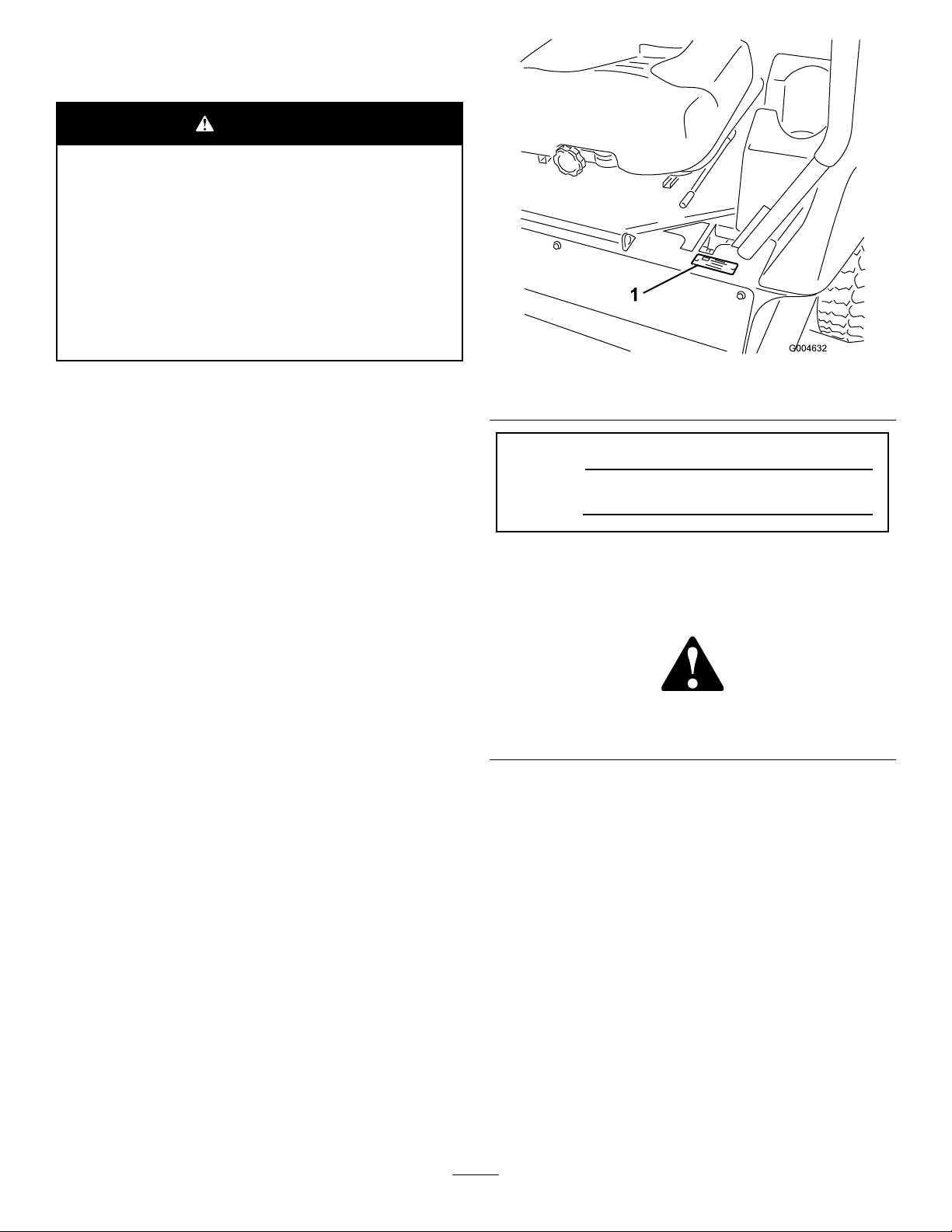
Figure1
1.Modelandserialnumberlocation
ModelNo.
SerialNo.
Introduction
Thismachineisaride-on,rotary-bladelawnmowerintended
tobeusedbyprofessional,hiredoperatorsincommercial
applications.Itisprimarilydesignedforcuttinggrass
onwell-maintainedlawnsinparks,sportselds,andon
commercialgrounds.Itisnotdesignedforcuttingbrush,
mowinggrassandothergrowthalongsidehighways,orfor
agriculturaluses.
Readthisinformationcarefullytolearnhowtooperateand
maintainyourproductproperlyandtoavoidinjuryand
productdamage.Youareresponsibleforoperatingthe
productproperlyandsafely.
YoumaycontactTorodirectlyatwww .Toro.comforproduct
safetyandoperationtrainingmaterials,accessoryinformation,
helpndingadealer,ortoregisteryourproduct.
Wheneveryouneedservice,genuineT oroparts,oradditional
information,contactanAuthorizedServiceDealerorToro
CustomerServiceandhavethemodelandserialnumbersof
yourproductready.Figure1identiesthelocationofthe
modelandserialnumbersontheproduct.Writethenumbers
inthespaceprovided.
Thismanualidentiespotentialhazardsandhassafety
messagesidentiedbythesafety-alertsymbol(Figure2),
whichsignalsahazardthatmaycauseseriousinjuryordeath
ifyoudonotfollowtherecommendedprecautions.
Figure2
1.Safety-alertsymbol
Thismanualuses2wordstohighlightinformation.
Importantcallsattentiontospecialmechanicalinformation
andNoteemphasizesgeneralinformationworthyofspecial
attention.
©2015—TheToro®Company
8111LyndaleAvenueSouth
Bloomington,MN55420
Contactusatwww.Toro.com.
2
PrintedintheUSA
AllRightsReserved
Page 3

Contents
Safety...........................................................................4
GeneralSafety.........................................................4
SafetyandInstructionalDecals.................................4
Setup............................................................................7
1CheckingFluidLevels............................................8
2ActivatingandChargingtheBattery.........................8
ProductOverview..........................................................9
Controls................................................................9
BeforeOperation......................................................11
BeforeOperationSafety..........................................11
AddingFuel...........................................................12
CheckingtheEngine-OilLevel.................................12
CheckingtheCoolingSystem...................................12
CheckingtheHydraulicSystem................................12
ThinkSafetyFirst...................................................13
UsingtheSafety-InterlockSystem.............................13
PositioningtheSeat................................................14
DuringOperation.....................................................15
DuringOperationSafety.........................................15
OperatingtheParkingBrake....................................16
StartingandShuttingofftheEngine..........................16
DrivingtheMachine...............................................17
EngagingthePowerTakeoff(PTO)..........................18
DisengagingthePTO.............................................18
AfterOperation........................................................18
AfterOperationSafety............................................18
PushingtheMachinebyHand..................................18
HaulingtheMachine...............................................19
Maintenance.................................................................20
RecommendedMaintenanceSchedule(s)......................20
DailyMaintenanceChecklist....................................21
PremaintenanceProcedures........................................22
Pre-MaintenanceSafety...........................................22
UnlatchingtheSeat.................................................22
Lubrication...............................................................23
GreasingtheBearingsandBushings..........................23
EngineMaintenance..................................................23
EngineSafety.........................................................23
CheckingtheAirCleaner.........................................23
ServicingtheEngineOil..........................................24
FuelSystemMaintenance...........................................25
ServicingtheWaterSeparator..................................25
CleaningtheFuelTank............................................26
CheckingtheFueltheLinesandConnections.............26
BleedingtheFuelSystem.........................................26
BleedingAirfromtheInjectors................................26
ElectricalSystemMaintenance....................................27
ElectricalSystemSafety...........................................27
ServicingtheBattery...............................................27
StoringtheBattery..................................................28
CheckingtheFuses.................................................28
CoolingSystemMaintenance......................................29
CheckingtheCoolingSystem..................................29
CleaningtheRadiator..............................................29
BrakeMaintenance....................................................30
AdjustingtheParking-BrakeInterlockSwitch.............30
BeltMaintenance......................................................30
CheckingtheAlternator-BeltTension........................30
ControlsSystemMaintenance.....................................31
AdjustingtheControl-Lever-NeutralInterlock
Switch...............................................................31
AdjustingtheControl-Lever-NeutralReturn..............31
AdjustingtheTractionDriveforNeutral....................32
AdjustingtheMaximumGroundSpeed.....................33
AdjustingtheTracking............................................33
HydraulicSystemMaintenance....................................34
HydraulicSystemSafety..........................................34
CheckingtheHydraulicSystem................................34
ChangingtheHydraulicFluidAndFilter....................35
Storage........................................................................36
Machine................................................................36
Engine..................................................................36
3
Page 4
Safety
ThismachinehasbeendesignedinaccordancewithCEN
standardISOEN5395:2013andANSIB71.4-2012whenthe
properCEKitshavebeeninstalledpertheDeclarationof
Conformity.
•Donotoperatethemachinewithoutallguardsandother
safetyprotectivedevicesinplaceandworkingonthe
machine.
•Keepclearofanydischargeopening.Keepbystandersa
safedistancefromthemachine.
•Keepchildrenoutoftheoperatingarea.Neverallow
childrentooperatethemachine.
GeneralSafety
Thisproductiscapableofamputatinghandsandfeetand
ofthrowingobjects.Alwaysfollowallsafetyinstructionsto
avoidseriouspersonalinjury.
Usingthisproductforpurposesotherthanitsintendeduse
couldprovedangeroustoyouandbystanders.
•ReadandunderstandthecontentsofthisOperator’ sManual
beforeyoustarttheengine.Ensurethateveryoneusing
thisproductknowshowtouseitandunderstandsthe
warnings.
•Donotputyourhandsorfeetnearmovingcomponents
ofthemachine.
SafetyandInstructionalDecals
Safetydecalsandinstructionsareeasilyvisibletotheoperatorandarelocatednearanyareaofpotential
danger.Replaceanydecalthatisdamagedorlost.
•Stopthemachineandshutofftheenginebeforeservicing,
fueling,oruncloggingthemachine.
Improperlyusingormaintainingthismachinecanresult
ininjury.T oreducethepotentialforinjury,complywith
thesesafetyinstructionsandalwayspayattentiontothe
safety-alertsymbol,whichmeansCaution,Warning,or
Danger—personalsafetyinstruction.Failuretocomplywith
theseinstructionsmayresultinpersonalinjuryordeath.
Youcanndadditionalitemsofsafetyinformationintheir
respectivesectionsthroughoutthismanual.
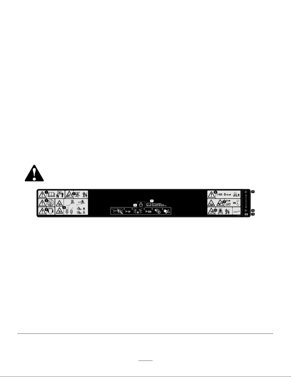
1.Warning—readtheOperator'sManualbeforeoperatingand
donotoperatethismachineunlessyouaretrained.
2.Crushing/dismembermenthazardofbystanders—donot
carrypassengers,keepbystandersasafedistancefromthe
machine.
3.Warning—donotusedrugsoralcohol.
4.Warning—wearhearingprotection.11.Disengage
5.Tipping,dropoffhazard—donotoperatenearwaterdrop-offs,
stayasafedistancefromdrop-offs,slowmachinebefore
turning,donotturnathighspeeds,wearaseatbeltwhen
aROPSisinplace,donotwearaseatbeltwhenROPSis
lowered.
6.Tostarttheengine:clearanydebrisfromtheattachment,
disengagethePTO,movethemotion-controlleverstothe
neutralposition,engagetheparkingbrake,turntheignitionto
Runandwaitfortheglowpluglighttoturnoff,turntheignition
keytoStart.
7.ReadtheOperator'sManual.
110-9772
8.Warning—engagetheparkingbrake,stoptheengineand
removetheignitionkeybeforeleavingthemachine.
9.Cuttinghazardofhandorfoot—removetheignitionkey
andreadtheinstructionsbeforeservicingorperforming
maintenance,keepawayfrommovingparts.
10.Thrownobjecthazard—keepbystandersasafedistancefrom
themachine;keepalldeectorsandshieldsinplace.
12.Engage
13.Parkingbrake
4
Page 5

110-9774
1.Forward
2.Fast4.Neutral6.Backward
3.Slow
5.Reverse7.Towvalvelocation;torque
thetowvalvesto6.78±
1.13N⋅m(60±10in-lb).
8.ReadtheOperator's
Manualformore
informationonthehydraulic
oil.
110-8254
1.Engine–Stop3.Engine—Start
2.Engine—Run
110-8253
1.PTO–Off4.Continuousvariable
setting
2.PTO—On5.Slow
3.Fast
110-9796
1.ReadtheOperator'sManualforinformationonfuses.
5
Page 6
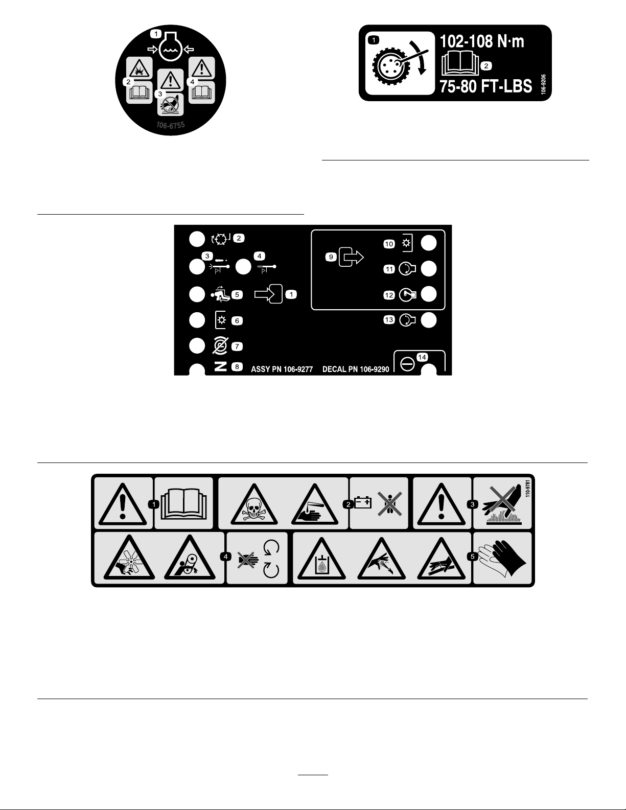
106-9206
1.Wheeltorquespecications
106-6755
2.ReadtheOperator'sManual.
1.Enginecoolantunder
pressure.
2.Explosionhazard—read
theOperator'sManual.
1.Inputs5.Inseat
2.Notactive
3.Hightemperatureshutdown
4.Hightemperaturewarning8.Neutral
3.Warning—donottouchthe
4.Warning—readthe
6.PowerT akeoff(PTO)10.PowerT akeoff(PTO)
7.Parkingbrakeoff11.Start
hotsurface.
Operator'sManual.
106-9290
9.Outputs13.Start
14.Power
12.EnergizetoRun(ETR)
110-9781
1.Warning—readtheOperator'sManual.
2.Poisonandcausticliquid/chemicalburnhazard—keepchildrenasafedistancefromthebattery.
3.Warning—donottouchthehotsurface.
4.Cutting/dismembermenthazard,fanandentanglementhazard,belt—stayawayfrommovingparts.
5.Hydraulicoilinsystemunderpressure,escapinghydraulicoilpenetratingskinhazard,brokenhydrauliclineshazard—wear
protectivehandprotectionwhenhandlinghydraulicsystemcomponents.
6
Page 7

Setup
LooseParts
Usethechartbelowtoverifythatallpartshavebeenshipped.
ProcedureDescription
1
2
Nopartsrequired
Nopartsrequired
MediaandAdditionalParts
Description
Operator'sManual
Engineowner’smanual1
PartsCatalog
Operatortrainingmaterials
Enginewarranty1
Qty.
–
–
Qty.
1
1Usetolookupandorderparts.
1
Readbeforeoperatingthemachine.
Readbeforeoperatingthemachine.
Viewbeforeoperatingthemachine.
Saveforfutureuse.
Use
Checkthehydraulicuid,engineoil,
andcoolantlevels.
Activateandchargethebattery.
Use
7
Page 8
1
CheckingFluidLevels
NoPartsRequired
Procedure
1.Checkthehydraulicuidlevelbeforestartingthe
engine;refertoCheckingtheHydraulicSystem(page
34).
2.Checktheengine-oillevelbeforeandafterstartingthe
engine;refertoCheckingtheEngine-OilLevel(page
24).
3.Checkthecoolingsystembeforestartingtheengine;
refertoCheckingtheCoolingSystem(page29).
3.Carefullylleachcellwithelectrolyteuntiltheplates
arecoveredwithabout6mm(1/4inch)ofuid(Figure
4).
Figure4
4.Waitapproximately20to30minutesfortheelectrolyte
tosoakintotheplates.
2
ActivatingandChargingthe Battery
NoPartsRequired
Procedure
Useonlyelectrolyte(1.265SpecicGravity)tollthebattery
initially.
1.Removethebatteryfromthemachine.
Important:Donotaddelectrolytewhilethe
batteryisinthemachine.Y oucouldspillit,
causingcorrosion.
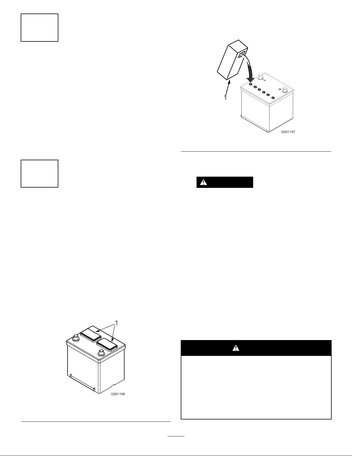
2.Cleanthetopofthebatteryandremovetheventcaps
(Figure3).
WARNING
Chargingthebatteryproducesgassesthatcan
explodeandcauseseriousinjuryordeath.
Neversmokenearthebatteryandkeepsparks
andamesawayfrombattery.
5.Fillthecellsasnecessarytobringtheelectrolyteto
withinabout6mm(1/4inch)ofthebottomofthell
well(Figure4).
6.Connecta3to4Abatterychargertothebatteryposts.
7.Chargethebatteryatarateof3to4Auntilthespecic
gravityis1.25orhigherandthetemperatureisatleast
16°C(60°F),withallcellsgassingfreely.
8.Whenthebatteryischarged,disconnectthecharger
fromtheelectricaloutletandbatteryposts.
Note:Afteryouactivatethebattery,addonly
distilledwatertoreplacenormalloss,although
maintenance-freebatteriesshouldnotrequirewater
undernormaloperatingconditions.
WARNING
1.Ventcaps
Figure3
CALIFORNIA
Proposition65Warning
Batteryposts,terminals,andrelated
accessoriescontainleadandleadcompounds,
chemicalsknowntotheStateofCalifornia
tocausecancerandreproductiveharm.
Washhandsafterhandling.
8
Page 9
WARNING
Batteryterminalsormetaltoolscouldshort
againstmetalcomponents,causingsparks.
Sparkscancausethebatterygassesto
explode,resultinginpersonalinjury.
•Whenremovingorinstallingthebattery,
donotallowthebatteryterminalstotouch
anymetalpartsofthemachine.
•Donotallowmetaltoolstoshortbetween
thebatteryterminalsandmetalpartsof
themachine.
9.Installthebatteryintothemachineandsecureit.
Note:Thebatteryshouldnotmoveorwigglewhen
pushed.
10.Installthepositivecable(red)tothepositive(+)
terminalandtheninstallthenegativecable(black)to
thenegative(-)terminalofthebattery.
ProductOverview
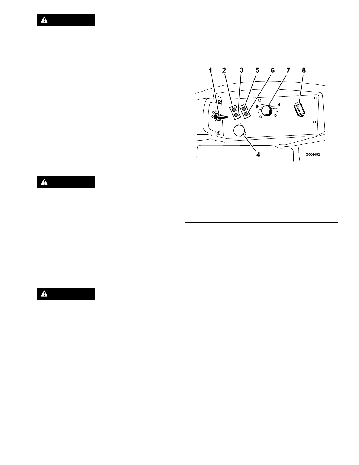
Controls
Becomefamiliarwithallthecontrolsbeforeyoustartthe
engineandoperatethemachine(Figure5).
Figure5
WARNING
Incorrectbatterycableroutingcoulddamage
themachineandcables,causingsparks.
Sparkscancausethebatterygassesto
explode,resultinginpersonalinjury.
•Alwaysdisconnectthenegative(black)
batterycablebeforedisconnectingthe
positive(red)cable.
•Alwaysconnectthepositive(red)battery
cablebeforeconnectingthenegative
(black)cable.
WARNING
Connectingcablestothewrongpostcould
damagetheelectricalsystemandresultin
personalinjury.
Important:Routethebatterycablesawayfrom
anysharpedgesormovingparts.
11.Slidetherubberbootoverthepositiveterminalto
preventapossibleshortfromoccurring.
1.Ignitionswitch
2.Engine-coolant-temperature
warninglight
3.Glow-pluglight
4.Power-takeoff(PTO)
switch
5.Oil-pressurewarninglight
6.Charge-indicatorlight
7.Throttlelever
8.Hourmeter
Motion-ControlLevers
Themotion-controlleverscontroltheforwardandrearward
motionsaswellastheturningofthemachine.Referto
DrivingtheMachine(page17).
IgnitionSwitch
Theignitionswitchhas3positions:OFF,ON/PREHEAT,and
START.
ThrottleLever
Thethrottlelevercontrolsthespeedoftheengine,thespeed
oftheblades,and,inconjunctionwithmotion-controllevers,
thegroundspeedofthemachine..Movingthethrottlelever
forwardtowardtheFASTpositionincreasestheenginespeed.
MovingitrearwardtowardtheSLOWpositiondecreasesthe
enginespeed.Alwaysrunthemachinewiththethrottleinthe
FASTpositionwhencuttinggrass.
Power-Takeoff(PTO)Switch
Thepower-takeoff(PTO)switchstartsandstopsthemower
blades.
9
Page 10
HourMeter
Thehourmeterrecordsthenumberofhoursthatyouoperate
themachinewiththekeyswitchintheRUNposition.Use
thesetimesforschedulingregularmaintenance.
Glow-PlugLight(OrangeLight)
Theglow-plugindicatorlightilluminateswhenyouturn
theignitionswitchtotheONposition.Itremainslitfor6
seconds.Whenthelightturnsoff,theengineisreadytostart.
Engine-Coolant-TemperatureWarning
Light
Thislightilluminatesandthecuttingbladesstopifthe
engine-coolanttemperatureishigh.Ifyoudonotstopthe
machineandthecoolanttemperaturerisesanother11°C
(20°F),theenginestops.
Important:Ifthemowerdeckshutsdownandthe
temperaturewarninglightison,pushthePTOknob
down,drivetoasafe,atarea,movethethrottleleverto
theSLOWposition,movethemotion-controlleversinto
theNEUTRAL-LOCKposition,andengagetheparking
brake.Idletheengineforseveralminuteswhileitcools
toasafelevel.Stoptheengineandcheckthecooling
system;refertoCheckingtheHydraulicSystem(page
34).
Charge-IndicatorLight
Thecharge-indicatorlightilluminateswhenthesystem
chargingcircuitmalfunctions.
Oil-Pressure-WarningLight
Figure6
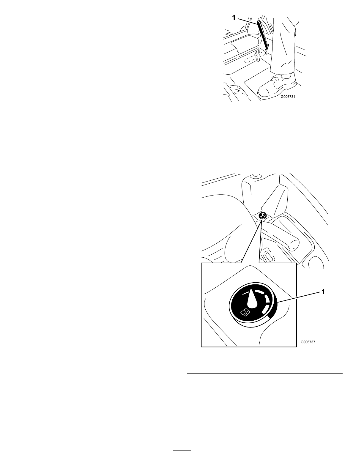
1.Parking-brakelever
FuelGauge
Thefuelgaugeindicatesthequantityoffuelremainingin
thefueltanks(Figure7).
Theoil-pressure-warninglightilluminateswhentheoil
pressureinenginedropsbelowasafelevel.Iftheoilpressure
islow,stoptheengineanddeterminethecause.Repairthe
damagebeforestartingtheengineagain.
Parking-BrakeLever
Wheneveryoushutofftheengine,engagetheparkingbrake
topreventaccidentalmovementofthemachine.Toengage
theparkingbrake,pulltheparking-brakeleverrearward
andup(Figure6).Toreleasetheparkingbrake,pushthe
parking-brakeleverforwardanddown.
Figure7
1.Fuelgauge
10
Page 11

Operation
FuelSafety
Note:Determinetheleftandrightsidesofthemachine
fromthenormaloperatingposition.
BeforeOperation
BeforeOperationSafety
GeneralSafety
•Read,understand,andfollowallinstructionsonthe
machineandinthemanual(s)beforestartingthemachine.
•Neverallowchildrenoruntrainedpeopletooperateor
servicethemachine.Localregulationsmayrestrictthe
ageoftheoperator.Theownerisresponsiblefortraining
alloperatorsandmechanics.
•Becomefamiliarwiththesafeoperationoftheequipment,
operatorcontrols,andsafetysigns.Knowhowtostop
themachineandenginequickly.
•Checkthatallsafetydevicesareattachedand
functioningproperly.Thisincludes,butisnotlimitedto,
operator-presencecontrols;safetyswitchesandshields;
therolloverprotectionsystem(ROPS);attachments;and
brakes.Donotoperatethemachineunlessallsafety
devicesareinpositionandfunctioningasintendedby
themanufacturer.
DANGER
Incertainconditions,fuelisextremelyammable
andhighlyexplosive.Areorexplosionfromfuel
canburnyouandothersandcandamageproperty.
•Fillthefueltankoutdoors,inanopenarea,when
theengineiscold.Wipeupanyfuelthatspills.
•Neverllthefueltankinsideanenclosedtrailer.
•Neversmokewhenhandlingfuel,andstayaway
fromanopenameorwherefuelfumesmaybe
ignitedbyaspark.
•Storefuelinanapprovedcontainerandkeepit
outofthereachofchildren.Neverbuymore
thana180-daysupplyoffuel.
•Donotoperatethemachinewithouttheentire
exhaustsysteminplaceandinproperworking
condition.
WARNING
Fuelisharmfulorfatalifswallowed.Long-term
exposuretovaporscancauseseriousinjuryand
illness.
•Avoidprolongedbreathingofvapors.
•Alwaysinspectthemachinetoensurethattheblades,
bladebolts,andcuttingassemblyarenotwornor
damaged.Replacewornordamagedbladesandboltsin
setstopreservebalance.
•Inspecttheareawhereyouwillusethemachineand
removeallobjectsthatthemachinecouldpotentially
throw .
•EnsurethatallthedrivesareintheNEUTRALposition,
theparkingbrakeisengaged,andthatyouareinthe
operatingpositionbeforeyoustarttheengine.
•Keepyourhandsandfaceawayfromthenozzle
andthefuel-tankopening.
•Keepfuelawayfromyoureyesandskin.
•Useonlyanapprovedfuelcontainer.
•Neverremovethefuelcaporaddfueltothefueltank
whiletheengineisrunning.
•Neverllcontainersinsideavehicleoronatruckor
trailerbedwithaplasticliner.Alwaysplacecontainerson
thegroundandawayfromyourvehiclebeforelling.
•Removetheequipmentfromthetruckortrailerandadd
fueltoitwhileitisontheground.Ifthisisnotpossible,
thenaddfuelusingaportablecontainerratherthanfrom
afuel-dispensernozzle.
•Keepthefuel-dispensernozzleincontactwiththerimof
thefueltankorcontaineropeningatalltimesuntilfueling
iscomplete.Donotuseanozzlelock-opendevice.
•Ifyouspillfuelonyourclothing,changeyourclothing
immediately.
•Fillthefueltankuntilthefuellevelis25mm(1inch)
belowthebottomofthellerneck.Donotoverllthe
fueltank.Replacethefuel-tankcapandtightenitsecurely .
11
Page 12
AddingFuel
RecommendedFuel
Useonlyclean,freshdieselfuelwithultralow(<15
ppm)sulfurcontentmeetingASTMD975orEN590
specications.Theminimumcetaneratingshouldbe40.
Purchasefuelinquantitiesthatcanbeusedwithin180days
toensurefuelfreshness.
Important:Useofnon-ultralowsulfurfuelcauses
damagetotheengineemissionsystem.
Fueltankcapacity:43.5L(11.5USgallons)
Usesummer-gradedieselfuel(No.2-D)attemperatures
above-7°C(20°F)andwintergrade(No.1-DorNo.
1-D/2-Dblend)belowthattemperature.Usingwinter-grade
fuelatlowertemperaturesprovideslowerashpointand
cold-owcharacteristics,whicheasesstartingandreduces
fuellterplugging.
Usingsummer-gradefuelabove-7°C(20°F)contributes
towardlongerfuel-pumplifeandincreasedpowercompared
towinter-gradefuel.
FillingtheFuelTank
Important:Thefueltanksareconnected,butthefuel
doesnottransferquicklyfromonetanktotheother.Itis
importantwhenllingthatyouparkonalevelsurface.
Ifyouparkonahill,youmayinadvertentlyoverllthe
tanks.
Important:Donotoverllthefueltanks.
Important:Donotopenthefueltankswhenparkedon
ahill.Thefuelcouldspillout.
Important:Donotusekeroseneorgasolineinstead
ofdieselfuel.Failuretoobservethiscautiondamages
theengine.
BiodieselReady
Thismachinecanalsouseabiodieselblendedfuelofup
toB20(20%biodiesel,80%petrodiesel).Thepetrodiesel
portionmustbeultralowsulfur.Observethefollowing
precautions:
•Thebiodieselportionofthefuelmustmeetspecication
ASTMD6751orEN14214.
•TheblendedfuelcompositionshouldmeetASTMD975
orEN590.
•Paintedsurfacesmaybedamagedbybiodieselblends.
•Monitorseals,hoses,gasketsincontactwithfuelasthey
maybedegradedovertime.
•Fuellterpluggingmaybeexpectedforatimeafter
convertingtobiodieselblendedfuel.
•Contactyourdistributorifyouwishmoreinformation
onbiodiesel.
Figure8
Note:Ifpossible,llthefueltanksaftereachuse.This
minimizesbuildupofcondensationinsidethefueltank.
CheckingtheEngine-OilLevel
Beforeyoustarttheengineandusethemachine,check
theoillevelintheenginecrankcase;refertoCheckingthe
Engine-OilLevel(page24).
CheckingtheCoolingSystem
Beforeyoustarttheengineandusethemachine,checkthe
coolingsystem;refertoCheckingtheCoolingSystem(page
29).
CheckingtheHydraulic System
Beforeyoustarttheengineandusethemachine,checkthe
hydraulicsystem;refertoCheckingtheHydraulicSystem
(page34).
12
Page 13

ThinkSafetyFirst
G009027
1
2
Pleasereadallsafetyinstructionsandsymbolsinthesafety
section.Knowingthisinformationcouldhelpyouor
bystandersavoidinjury.
DANGER
Operatingonicyorsteepslopescancausesliding
andlossofcontrol.
Atrackdroppingoveranedgecancausearollover,
whichmayresultinseriousinjury,death,or
drowning.
Alwaysusetheseatbeltwhentherollbarisup.
Readandfollowtherollover-protectioninstructions
andwarnings.
Toavoidlossofcontrolandpossibilityofrollover:
•Donotoperateneardrop-offsornearwater.
•Reducespeedanduseextremecautionon
slopes.
•Avoidsuddenturnsorrapidspeedchanges.
Figure10
1.Weareyeprotection.2.Wearhearingprotection.
UsingtheSafety-Interlock System
CAUTION
Ifthesafety-interlockswitchesaredisconnectedor
damaged,themachinecouldoperateunexpectedly,
causingpersonalinjury.
•Donottamperwiththeinterlockswitches.
•Checktheoperationoftheinterlockswitches
dailyandreplaceanydamagedswitchesbefore
operatingthemachine.
UnderstandingtheSafety-Interlock
System
Thesafety-interlocksystempreventstheenginefromstarting
unless:
•Youaresittingontheseatortheparkingbrakeisengaged.
•Thepowertakeoff(PTO)isdisengaged.
•Themotion-controlleversareintheNEUTRAL-LOCK
position.
•Theenginetemperatureisbelowthemaximumoperating
temperature.
Figure9
1.SafeZone3.Water/unsafeice
2.Usewalk-behind
equipmentneardrop-offs
andwater.
Thesafety-interlocksystemalsostopstheenginewhenyou
movethetractioncontrolsfromtheNEUTRAL-LOCKposition
withtheparkingbrakeengaged.Ifyourisefromtheseat
whenthePTOisengaged,thereisa1-seconddelayandthen
theenginestops.
TestingtheSafety-InterlockSystem
CAUTION
Thismachineproducessoundlevelsinexcessof
85dBAattheoperator’searandcancausehearing
lossthroughextendedperiodsofexposure.
Wearhearingprotectionwhenoperatingthis
machine.
Theuseofprotectiveequipmentforeyes,ears,hands,feet,
andheadisrecommended.
ServiceInterval:Beforeeachuseordaily
Testthesafety-interlocksystembeforeyouusethemachine
eachtime.Ifthesafetysystemdoesnotoperateasdescribed
below,haveanAuthorizedServiceDealerrepairthesafety
systemimmediately.
1.Sitontheseat,engagetheparkingbrake,andmovethe
PTOtotheONposition.Trystartingtheengine;the
engineshouldnotcrank.
13
Page 14

2.Sitontheseat,engagetheparkingbrake,andmovethe
PTOtotheOFFposition.Moveeithermotion-control
leveroutoftheNEUTRAL-LOCKposition.Trystarting
theengine;theengineshouldnotcrank.Repeatfor
othermotion-controllever.
3.Sitontheseat,engagetheparkingbrake,movethe
PTOswitchtotheOFFposition,andmovethe
motion-controlleverstotheNEUTRAL-LOCKposition.
Starttheengine.Whiletheengineisrunning,release
theparkingbrake,engagethePTO,andriseslightly
fromtheseat;theengineshouldstopwithin2seconds.
4.Withoutanoperatorontheseat,engagetheparking
brake,movethePTOswitchtotheOFFposition,and
movethemotion-controlleverstotheNEUTRAL-LOCK
position.Starttheengine.Whiletheengineisrunning,
centereithermotioncontrol;theengineshouldstop
within2seconds.Repeatfortheothermotion-control
lever.
5.Withoutanoperatorontheseat,disengagetheparking
brake,movethePTOswitchtotheOFFposition,and
movethemotion-controlleverstotheNEUTRAL-LOCK
position.Trystartingtheengine;theengineshould
notcrank.
UsingtheSCMtoDiagnoseSystem
Problems
Themachineisequippedwithastandardcontrolmodule
(SCM)monitoringsystemthattracksthefunctionofvarious
keysystems.TheSCMislocatedundertherightcontrol
panel.Accessitthroughthesidepanelcover(Figure11).
Toopenthesidepanelcover,releasethe2latchesandpull
outonit.
theselightsforsystemdiagnosis.RefertoFigure12fora
descriptionofwhateachlightmeans.Fordetailsonusingthe
restoftheSCMfunctions,refertotheServiceManual,available
throughyourAuthorizedToroDistributor.
Figure12
1.Hightemperatureshutdown—theenginetemperaturehas
exceededsafelevelsandtheenginehasbeenshutdown.
Checkthecoolingsystem.
2.Hightemperaturewarning—theenginetemperatureis
approachingunsafelevelsandthemowerdeckhasbeen
shutdown.Checkthecoolingsystem.
3.Operatorisintheseat.
4.ThePTOison.
5.Theparkingbrakeisnotengaged.
6.Controlsareinneutral.
7.TheSCMisreceivingpowerandisoperational.
PositioningtheSeat
Figure11
1.Sidepanelcover
2.Latches
OnthefaceoftheSCMare11LEDsthatilluminate
toindicatevarioussystemconditions.Youcanuse7of
Figure13
1.Back-restknob3.Lumbar-support-adjustment
knob
2.Seat-suspensionknob4.Seat-position-adjustment
lever
14
Page 15

ChangingtheSeatPosition
Youcanmovetheseatforwardandbackward.Positionthe
seatwhereyouhavethebestcontrolofthemachineandare
mostcomfortable.
Figure14
ChangingtheSeatSuspension
Youcanadjusttheseatforasmoothandcomfortableride.
Positiontheseatwhereyouaremostcomfortable.
Withoutsittingontheseat,turntheknobinfronteither
direction(Figure13).
Figure15
1.Seat-suspensionknob2.Operator-weightsetting
ChangingtheBackPosition
Youcanadjustthebackoftheseatforacomfortableride.
Positionthebackoftheseatwhereyouaremostcomfortable.
Toadjustit,turntheknob,undertherightarmrest,ineither
direction(Figure13).
ChangingtheLumbarSupport
Youcanadjustthelumbarsupportforyourlowerback.
Toadjustit,turntheknob,undertheleftarmrest,ineither
direction(Figure13).
DuringOperation
DuringOperationSafety
GeneralSafety
•Theowner/usercanpreventandisresponsiblefor
accidentsthatmaycauseinjuriestohimself/herselfand
othersandfordamagetoproperty.
•Wearappropriateclothing,includingeyeprotection;
slip-resistant,substantialfootwear;andhearing
protection.Wearingsafetyshoesandlongpantsis
advisableandrequiredbysomelocalordinancesand
insuranceregulations.Tiebacklonghair,secureloose
clothing,anddonotwearjewelry.
•EnsurethatalldrivesareintheNEUTRALposition,the
parkingbrakeisengaged,andyouareintheoperating
positionbeforeyoustarttheengine.
•Keepallbodyparts,includinghandsandfeet,awayfrom
allmovingparts.
•Donotoperatethemachinewhileill,tired,orunderthe
inuenceofalcoholordrugs.
•Keepthedirectionofthemowerdischargeawayfrom
peopleandpets.
•Donotmowinreverseunlessitisabsolutelynecessary.If
youmustmowinreverse,lookbehindanddownforsmall
childrenbeforeandwhilemovingthemachineinreverse.
Stayalertandstopthemachineifachildentersthearea.
•Useextremecarewhenapproachingblindcorners,
shrubs,trees,orotherobjectsthatmayblockyourview.
•Donotmowneardrop-offs,ditches,orembankments.
Themachinecouldsuddenlyrolloverifawheelgoes
overtheedgeoriftheedgecavesin.
•Nevercarrypassengersonthemachine.
•Operatethemachineonlyingoodvisibilityand
appropriateweatherconditions.Donotoperatethe
machinewhenthereistheriskoflighting.
•Donotmowonwetgrass.Reducedtractioncouldcause
themachinetoslide.
•Neverraisethemowerdeckwiththebladesrunning.
•Stopthemachineandinspectthebladesafterstrikingan
objectorifthereisanabnormalvibrationinthemachine.
Makeallnecessaryrepairsbeforeresumingoperation.
•Stopthebladeswheneveryouarenotmowing,especially
whilecrossinglooseterrainsuchasgravel.
•Slowdownandusecautionwhenmakingturnsand
crossingroadsandsidewalkswiththemachine.Always
yieldtheright-of-way.
•Turnontheashingwarninglightsonthemachine
wheneveryoutravelonapublicroad,exceptwheresuch
useisprohibitedbylaw.
•Disengagethedrivetotheattachmentandshutoffthe
enginebeforeaddingfuelandadjustingtheheightofcut.
15
Page 16

•Reducethethrottlesettingbeforestoppingtheengine
and,iftheenginehasafuel-shutoffvalve,shutoffthe
fuelwhenyouhavenishedoperatingthemachine.
•Neverrunanengineinanareawhereexhaustgasesare
enclosed.
•Neverleavearunningengineunattended.
•Beforeleavingtheoperatingposition,dothefollowing:
–Stopthemachineonlevelground.
–Disengagethepowertake-offandlowerthe
attachments.
–Settheparkingbrake.
–Shutofftheengineandremovethekey .
–Waitforallmovingpartstostop.
•Donotchangethegovernorsettingsonoroverspeed
theengine.Operatingtheengineatexcessivespeedmay
increasethepotentialforpersonalinjury.
•Donotusethemachineasatowingvehicle.
•UseaccessoriesandattachmentsapprovedbyTheToro®
Companyonly.
RolloverProtectionSystem(ROPS)
Safety
•DonotremovetheROPSfromthemachine.
•Ensurethattheseatbeltisattachedandthatyoucan
releaseitquicklyintheeventofanemergency.
•AlwayswearyourseatbeltwhentheROPSisup.
•Checkcarefullyforoverheadclearances,suchasbranches,
doorways,andelectricalwires,beforedrivingthemachine
underthem.Donotcontactthem.
•KeeptheROPSinsafeoperatingconditionbythoroughly
inspectingitperiodicallyfordamageandkeepingallthe
mountingfastenerstight.
•ReplaceadamagedROPS.Donotrepairorreviseit.
•AnyalterationstoaROPSmustbeapprovedbyThe
Toro®Company.
OperatingtheParkingBrake
Alwayssettheparkingbrakewhenyoustopthemachineor
leaveitunattended.
SettingtheParkingBrake
WARNING
Theparkingbrakemaynotholdthemachine
parkedonaslopeandcouldcausepersonalinjury
orpropertydamage.
Donotparkthemachineonslopesunlessthe
wheelsarechockedorblocked.
Figure16
ReleasingtheParkingBrake
Figure17
SlopeSafety
•Slowdownthemachineanduseextracareonhillsides.
Travelintherecommendeddirectiononhillsides.Turf
conditionscanaffectthestabilityofthemachine.
•Avoidstarting,stopping,orturningthemachineona
slope.Ifthetireslosetraction,disengagetheblade(s)and
proceedslowlystraightdowntheslope.
•Donotturnthemachinesharply .Usecarewhenreversing
themachine.
•Whenoperatingthemachineonaslope,alwayskeepall
cuttingunitslowered.
•Avoidturningthemachineonslopes.Ifyoumustturn,
turnslowlyandgraduallydownhill,ifpossible.
•Useextracarewhileoperatingthemachinewith
attachments;theycanaffectthestabilityofthemachine.
StartingandShuttingoffthe Engine
StartingtheEngine
Note:Theglowpluglightilluminatesfor6secondswhen
youturntheignitionkeytotheRUNposition.Turnthe
ignitiontotheSTARTpositionafterthelightgoesout.
Important:Usestartingcyclesofnomorethan
15secondsperminutetoavoidoverheatingthestarter
motor.
Important:Whenyoustarttheenginefortherst
time,changetheengineoiloroverhaultheengine,
transmission,orwheelmotorandoperatethemachine
16
Page 17

withthethrottleleverintheSLOWpositioninboth
theforwardandreversedirectionsfor1to2minutes.
OperatetheliftleverandPTOlevertoensurethat
theyoperateproperly.Shuttheengineoff,checkuid
levels,andcheckforoilleaks,looseparts,andanyother
noticeablemalfunctions.
Figure19
DrivingtheMachine
Thethrottlecontrolregulatestheenginespeedasmeasuredin
rpm(revolutionsperminute).Placethethrottlecontrolinthe
FASTpositionforbestperformance.Alwaysoperateinthe
FASTthrottlepositionwhenrunningpoweredattachments.
Figure18
Note:LeavethethrottlemidwaybetweentheSLOWand
FASTpositionsuntiltheengineandhydraulicsystemwarmup.
ShuttingofftheEngine
CAUTION
Childrenorbystandersmaybeinjuredifthey
attempttomoveoroperatethetractorwhileitis
unattended.
Alwaysremovetheignitionkeyandsettheparking
brakewhenleavingthemachineunattended,even
ifjustforafewminutes.
CAUTION
Themachinecanturnveryrapidly.Youmaylose
controlofitandcausepersonalinjuryordamage
themachine.
•Usecautionwhenmakingturns.
•Slowthemachinedownbeforemakingsharp
turns.
1.Releasetheparkingbrake.
Note:Theengineshutsoffifyoumovethe
motion-controlleversoutoftheNEUTRAL-LOCK
positionwiththeparkingbrakeengaged.
2.Movetheleverstothecenter,unlockedposition.
3.Drivethemachineasfollows:
•Tomovestraightforward,slowlypushthe
motion-controlleversforward(Figure20).
•Tomovestraightrearward,slowlypullthe
motion-controlleversrearward(Figure20).
•Toturn,slowthemachinebypullingbackonboth
leversandthenpushforwardontheleveronthe
oppositesidefromwhichyouwanttoturn(Figure
20).
•Tostop,pullthemotion-controlleverstothe
NEUTRALposition.
Note:Thefartheryoumovethemotion-controllevers
ineitherdirection,thefasterthemachinemovesinthat
direction.
17
Page 18

Figure20
G008945
G009174
1.Motion-control
lever—NEUTRAL-LOCK
position
2.Center,unlockedposition
3.Forward
4.Backward
EngagingthePowerTakeoff (PTO)
Thepower-takeoff(PTO)switchstartsandstopspowered
attachments.
Note:Iftheengineiscold,allowtheenginetowarmup5
to10minutesbeforeengagingthePTO.
DisengagingthePTO
Figure22
AfterOperation
AfterOperationSafety
GeneralSafety
•Cleangrassanddebrisfromthecuttingunits,drives,
mufers,andenginetohelppreventres.Cleanupoil
orfuelspills.
•Shutoffthefuelwhilestoringortransportingthe
machine,ifapplicable.
•Disengagethedrivetotheattachmentwheneveryouare
transportingornotusingthemachine.
•Usefull-widthrampsforloadingthemachineintoa
trailerortruck.Donotexceeda15°anglebetweenthe
rampandthetrailerortruck.
•Tiethemachinedownsecurelyusingstraps,chains,cable,
orropes.Bothfrontandrearstrapsshouldbedirected
downandoutwardfromthemachine.
•Allowtheenginetocoolbeforestoringthemachinein
anyenclosure.
•Neverstorethemachineorfuelcontainerwherethereis
anopename,spark,orpilotlight,suchasonawater
heateroronotherappliances.
Figure21
PushingtheMachinebyHand
Ifthemachinebreaksdown,runsoutoffuel,etc.,youmay
needtopullitwithawinchtoloaditontoatrailer.Todoso,
yourstneedtoopenthehydraulicbypassvalves.
Important:Nevertowthemachine,becausehydraulic
damagemayoccur.
ChangingtoMachineOperation
Rotateeachbypassvalveclockwise1turnandhand-tighten
them(Figure23).
Note:Thetorqueshouldbeapproximately8N∙m(71in-lb).
Donotovertightenthebypassvalves.
Youcannotdrivethemachineunlessthebypassvalvesare
turnedinward.
18
Page 19

Figure23
1.By-passvalves
HaulingtheMachine
•Usecarewhenloadingorunloadingthemachineintoa
traileroratruck.
•Usefull-widthrampsforloadingthemachineintoa
traileroratruck.
•Tiethemachinedownsecurelyusingstraps,chains,cable,
orropes.Bothfrontandrearstrapsshouldbedirected
downandoutwardfromthemachine.
Figure24
1.Fronttie-downs
2.Reartie-down(leftside
shown)
19
Page 20

Maintenance
Note:Determinetheleftandrightsidesofthemachinefromthenormaloperatingposition.
RecommendedMaintenanceSchedule(s)
MaintenanceService
Interval
Aftertherst10hours
Aftertherst50hours
Aftertherst200hours
Beforeeachuseordaily
Every50hours
Every100hours
Every150hours
Every200hours
Every400hours
MaintenanceProcedure
•Checkthealternator-belttension.
•Torquethewheellugnuts.
•Changetheengineoilandlter.
•Changethehydraulicuidandlter.
•Testthesafety-interlocksystem.
•Checktheengine-oillevel.
•Drainwaterorothercontaminantsfromthewaterseparator.
•Checktheengine-coolantlevel.
•Cleantheradiatorwithcompressedair(moreoftenindirtyanddustyconditions).
•Checkthehydraulicuidlevel.
•Greasethebearingandbushinggreasettings(moreoftenindirtyordusty
conditionsandaftereverywashing).
•Checkthebatterycableconnections.
•Checkthealternator-belttension.
•Changetheengineoilandlter.
•Inspectthecooling-systemhosesandseals.Replacethemifcrackedortorn.
•Torquethewheellugnuts.
•Servicetheaircleaner.
•Replacethefuel-ltercanisterforthewaterseparator.
•Checkthefuellinesandconnections.
Every800hours
Every1,500hours
Every2years
•Changethehydraulicuidandlter.
•Inspecttheengine-valveclearance.Refertoyourengineownersmanual.
•Replacemovinghoses.
•Drainandcleanthefueltank.
•Flushandreplacethecooling-systemuid.
Important:Refertoyourengineowner'smanualforadditionalmaintenanceprocedures.AdetailedServiceManual
isalsoavailableforpurchasefromyourAuthorizedToroDistributor.
20
Page 21

DailyMaintenanceChecklist
Duplicatethispageforroutineuse.
Fortheweekof: MaintenanceCheckItem
Checkthesafety-interlock
operation.
Checktheparking-brake
operation.
Checkthefuellevel.
Checkthehydraulicoillevel.
Checktheengine-oillevel.
Checkthecooling-system
uidlevel.
Checkthedrainwater/fuel
separator.
Checktheair-lterrestriction
indicator.
Checktheradiatorand
screenfordebris
Checkforunusualengine
noises.
Checkforunusualoperating
noises.
Checkthehydraulichoses
fordamage
Checkforuidleaks.
Checkthetirepressure.
Checktheinstrument
operation.
Lubricateallgreasettings.
Touchupdamagedpaint.
1.Iftheindicatorshowsred
1
2
3
Mon.Tues.Wed.Thurs.Fri.
Sat.Sun.
2.Checktheglowplugandinjectornozzlesifyounoticehardstarting,excesssmoke,orroughrunning.
3.Immediatelyaftereverywashing,regardlessoftheintervallisted.
NotationforAreasofConcern
Inspectionperformedby:
ItemDate
21
Information
Page 22

CAUTION
G020871
1
Ifyouleavethekeyintheignitionswitch,someonecouldaccidentlystarttheengineandseriouslyinjure
youorotherbystanders.
Removethekeyfromtheignitionbeforeyoudoanymaintenance.
Premaintenance
Procedures
Important:Thefastenersonthecoversofthismachine
aredesignedtoremainonthecoverafterremoval.
Loosenallofthefastenersoneachcoverafewturns
sothatthecoverisloosebutstillattached,thengo
backandloosenthemuntilthecovercomesfree.This
preventsyoufromaccidentallystrippingtheboltsfree
oftheretainers.
Pre-MaintenanceSafety
•Keepallpartsofthemachineingoodworkingcondition
andallhardwaretightened,especiallyblade-attachment
hardware.Replaceallwornordamageddecals.
•Neverallowuntrainedpersonneltoservicethemachine.
•Beforeadjusting,cleaning,orrepairingthemachine,do
thefollowing:
1.Movethemachinetolevelground.
2.Disengagethedrives.
•Ifyourmachinerequiresmajorrepairsorifyoudesire
assistance,contactanAuthorizedToroDistributor.
•UseonlygenuineTororeplacementpartsandaccessories.
Replacementpartsandaccessoriesmadebyother
manufacturerscouldbedangerous,andsuchusecould
voidtheproductwarranty.
UnlatchingtheSeat
Toaccessthehydraulicandothersystemsundertheseat,
unlatchtheseatandswingitforward.
1.Usetheseat-positionadjustmentlevertoslidetheseat
allthewayforward.
2.Pulltheseatlatchleverforwardandliftuptounlatch
theseat(Figure25).
3.Lowerthecuttingunits.
4.MovethetractionpedaltotheNEUTRALposition.
5.Engagetheparkingbrake.
6.MovethethrottleswitchtotheLOW-IDLEposition.
7.Shutofftheengineandremovethekey.
8.Waitforallmovingpartstostop.
•Wheneveryouparkorstorethemachine,orleaveit
unattended,lowerthecuttingunitsunlessyouusea
positivemechanicallock.
•Ifpossible,donotperformmaintenanceonthemachine
whiletheengineisrunning.Ifyoumustruntheengineto
performmaintenanceonthemachine,keepyourhands,
feet,otherbodyparts,andclothingawayfromallmoving
parts,themower-dischargearea,andtheundersideof
themowers.
•Donottouchpartsofthemachineoranattachment
thatmaybehotfromoperation.Allowthepartstocool
beforeattemptingtomaintain,adjust,orservicethem.
•Usejackstandstosupportthemachineand/orits
componentswhenrequired.
Figure25
1.Seatlatch
•Carefullyreleasepressurefromcomponentswithstored
energy.
22
Page 23

Lubrication
G004501
123456
7
EngineMaintenance
GreasingtheBearingsand Bushings
ServiceInterval:Every50hours(moreoftenindirty
ordustyconditionsandafterevery
washing).
GreaseType:No.2lithiumgrease.
Important:Lubricatethegreasettingsimmediately
aftereverywashing,regardlessofintervalspecied.
Bearinglifecanbenegativelyaffectedbyimproperwash
downprocedures.Donotwashdowntheunitwhenit
isstillhotandavoiddirectinghigh-pressureorhigh
volumesprayatthebearingsorseals.
1.Wipethegreasettingscleansothatforeignmatter
cannotbeforcedintothebearingorbushing.
2.Pumpgreaseintothettings.
3.Wipeoffexcessgrease.
EngineSafety
Shutofftheenginebeforecheckingtheoiloraddingoilto
thecrankcase.
CheckingtheAirCleaner
1.Checktheair-cleanerbodyfordamage,which
couldpossiblycauseanairleak.Replaceadamaged
air-cleanerbody .
2.Checktheair-intakesystemforleaks,damage,orloose
hoseclamps(Figure26).
Important:Donotover-servicetheairlter.
Figure26
1.Air-cleanercover5.Air-cleanerbody
2.Air-cleanerlatch6.Air-cleanerindicator
3.Gasket
4.Filter
3.Besurethatthecoverisseatedcorrectlyandsealswith
theair-cleanerbody.
7.Rubberoutletvalve
ServicingtheAirCleaner
ServiceInterval:Every400hours
Note:Ifthefoamgasketinthecoverisdamaged,replaceit.
Important:Avoidusinghigh-pressureair,whichcould
forcedirtthroughthelterintotheintaketract.
Important:Donotcleantheusedltertoavoid
damagingtheltermedia.
Important:Donotuseadamagedlter.
Important:Donotapplypressuretotheexiblecenter
ofthelter.
23
Page 24

Note:T oroPremiumEngineoilisavailablefromyour
distributorineither15W-40or10W-30viscosity.Seethe
partscatalogforpartnumbers.
1.Parkthemachineonalevelsurface,lowerthemower
deck,movethethrottlelevertotheSLOWposition,
stoptheengine,andremovethekeyfromtheignition
switch.
2.Openthehood.
3.Checktheengineoil
Figure27
ServicingtheEngineOil
CheckingtheEngine-OilLevel
ServiceInterval:Beforeeachuseordaily
Theengineisshippedwithoilinthecrankcase;however,
checktheoillevelbeforeandafteryourststarttheengine.
Checktheoillevelbeforeoperatingthemachineeachdayor
eachtimeyouusethemachine.
Thecrankcasecapacityisapproximately3.8L(4.0qt)with
thelter.Usehigh-qualityengineoilthatmeetsthefollowing
specications:
•APIClassicationLevelRequired:CH-4,CI-4orhigher.
•Preferredoil:SAE15W-40(above-17°C(0°F)
•Alternateoil:SAE10W-30or5W-30(alltemperatures)
Figure28
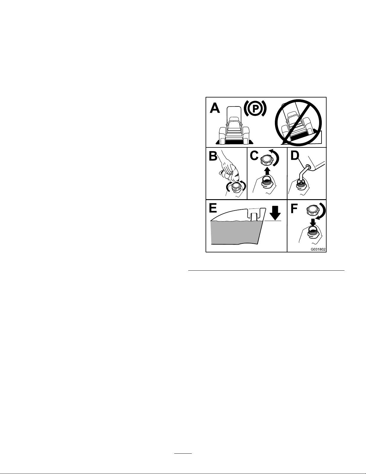
ChangingtheEngineOilandFilter
ServiceInterval:Aftertherst50hours
Every150hours
Ifpossible,runtheenginejustbeforechangingtheoil,
becausewarmoilowsbetterandcarriesmorecontaminants
thancoldoil.
1.Positionthemachineonalevelsurface.
2.Openthehood.
3.Changetheoil(Figure29).
24
Page 25

Figure29
B
A
C D
E
F
3/4
g027477
4.Replacetheoillter(Figure30).
FuelSystem
Maintenance
DANGER
Undercertainconditions,dieselfuelandfuel
vaporsarehighlyammableandexplosive.Are
orexplosionfromfuelcanburnyouandothersand
cancausepropertydamage.
•Useafunnelandllthefueltankoutdoors,in
anopenarea,whentheengineisoffandiscold.
Wipeupanyfuelthatspills.
•Donotllthefueltankcompletelyfull.Addfuel
tothefueltankuntilthelevelistothebottom
ofthellerneck.
•Neversmokewhenhandlingfuel,andstayaway
fromanopenameorwherefuelfumesmaybe
ignitedbyaspark.
•Storefuelinaclean,safety-approvedcontainer
andkeepthecapinplace.
5.Fillthecrankcasewithoil;refertoCheckingthe
Engine-OilLevel(page24).
ServicingtheWaterSeparator
ServiceInterval:Every400hours
Beforeeachuseordaily
Figure30
25
Page 26

BleedingtheFuelSystem
CAUTION
Theenginemaystartduringthisprocedure.
Movingfansandbeltsinarunningenginecan
severelyinjureyouorbystanders.
Keephands,ngers,looseclothing/jewelry,and
hairawayfromtheenginefanandbeltduringthis
procedure.
1.Parkthemachineonalevelsurface.Ensurethatthe
fueltankisatleasthalffull.
2.Unlatchandraisethehood.
3.Placearagundertheair-bleedscrewonthe
fuel-injectionpumpandopenit(Figure32).
Figure31
CleaningtheFuelTank
ServiceInterval:Every2years
Removeandcleanthein-linestrainersafterdrainingthetank.
Usecleandieselfueltoushoutthetank.
Important:Drainandcleanthetankifthefuelsystem
becomescontaminatedorifyouarestoringthemachine
foranextendedperiod.
CheckingtheFueltheLines andConnections
ServiceInterval:Every400hours/Yearly(whichevercomes
rst)
Inspectthefuellinesfordeterioration,damage,chafng,or
looseconnections.
Figure32
1.Fuel-injection-pumpbleedscrew
4.TurntheignitionkeytotheONposition.
Note:Theelectricfuelpumpbeginsoperation,
therebyforcingairoutattheair-bleedscrew.
5.LeavethekeyintheONpositionuntilasolidstream
offuelowsoutaroundthescrew .
6.TightenthescrewandturnkeytotheOFFposition.
Note:Normally,theengineshouldstartafteryou
bleedthefuelsystem.However,ifenginedoesnot
start,airmaybetrappedbetweeninjectionpumpand
injectors;refertoBleedingAirfromtheInjectors(page
26).
BleedingAirfromtheInjectors
Note:Usethisprocedureonlyifyoupurgedthefuelsystem
throughnormalprimingproceduresandtheenginedoesnot
start;refertoBleedingtheFuelSystem(page26).
1.Placearagunderthepipeconnectioncomingfrom
theinjectionpumptotheNo.1injectornozzleas
illustratedinFigure33.
26
Page 27

Figure33
1.PipeconnectionfromtheinjectionpumptotheNo.1
injectornozzle
2.MovethethrottletotheFASTposition.
3.TurntheignitionkeytheSTARTpositionandwatchthe
fuelowaroundtheconnector.
CAUTION
Theenginemaystartduringthisprocedure.
Movingfansandbeltsinarunningenginecan
severelyinjureyouorbystanders.
Keephands,ngers,looseclothing/jewelry,
andhairawayfromtheenginefanandbelt
duringthisprocedure.
ElectricalSystem
Maintenance
Important:Wheneverworkingwiththeelectrical
system,alwaysdisconnectthebatterycables,negative
(-)cablerst,topreventpossiblewiringdamagefrom
short-outs.
ElectricalSystemSafety
•Disconnectthebatterybeforerepairingthemachine.
Disconnectthenegativeterminalrstandthepositive
last.Connectthepositiveterminalrstandthenegative
last.
•Batteryacidispoisonousandcancauseburns.Avoid
contactwithyourskin,eyes,andclothing.Protectyour
face,eyes,andclothingwhenworkingwithabattery.
•Batterygasescanexplode.Keepcigarettes,sparks,and
amesawayfromthebattery.
•Chargethebatteriesinanopen,well-ventilatedarea,
awayfromsparksandames.Unplugthechargerbefore
connectingordisconnectingthebattery.Wearprotective
clothinganduseinsulatedtools.
•Donotuseapressurewashernearanyelectronic
components.
WARNING
4.Tightenthepipeconnectorsecurelywhenitattainsa
solidow .
5.TurnthekeytotheOFFposition.
6.Repeatthisprocedurefortheremainingnozzles.
CALIFORNIA
Proposition65Warning
Batteryposts,terminals,andrelated
accessoriescontainleadandleadcompounds,
chemicalsknowntotheStateofCalifornia
tocausecancerandreproductiveharm.
Washhandsafterhandling.
ServicingtheBattery
ServiceInterval:Every50hours
Ifyoustorethemachineinalocationwheretemperaturesare
extremelyhigh,thebatteryrunsdownmorerapidlythanifthe
machineisstoredinalocationwherethetemperatureiscool.
Keepthetopofthebatterycleanbywashingitperiodically
withabrushdippedinammoniaorbicarbonatesodasolution.
Flushthetopsurfacewithwateraftercleaningit.
Important:Donotremovethellcapswhilecleaning
thebattery.
Thebatterycablesmustbetightontheterminalstoprovide
goodelectricalcontact.
Ifcorrosionoccursattheterminals,disconnectthecables,
negative(-)cablerst,andscrapetheclampsandterminals
27
Page 28

separately.Connectthecables,positive(+)cablerst,and
coattheterminalswithpetroleumjelly.
WARNING
Batteryterminalsormetaltoolscouldshortagainst
metalmachinecomponents,causingsparks.Sparks
cancausethebatterygassestoexplode,resulting
inpersonalinjury.
•Whenremovingorinstallingthebattery,donot
allowthebatteryterminalstotouchanymetal
partsofthemachine.
•Donotallowmetaltoolstoshortbetween
thebatteryterminalsandmetalpartsofthe
machine.
Figure34
WARNING
Incorrectbatterycableroutingcoulddamagethe
machineandcables,causingsparks.Sparkscan
causethebatterygassestoexplode,resultingin
personalinjury.
•Alwaysdisconnectthenegative(black)battery
cablebeforedisconnectingthepositive(red)
cable.
•Alwaysconnectthepositive(red)batterycable
beforeconnectingthenegative(black)cable.
StoringtheBattery
Ifyouarestoringthemachinemorethan30days,removethe
batteryandchargeitfully .Eitherstoreitonashelforonthe
machine.Donotconnectthecablesifyoustoreitonthe
machine.Storethebatteryinacoolenvironmenttoprevent
thebatteryfromdischargingrapidly.Topreventthebattery
fromfreezing,makesurethatitisfullycharged.Thespecic
gravityofafullychargedbatteryis1.265to1.299.
1.Sidepanelcover
2.Latches
Figure35
CheckingtheFuses
Themachinefusesarelocatedunderthecontrolpanel.
Accessthemthroughthesidepanelcover(Figure34).To
openthesidepanelcover,releasethe2latchesandpullout
onit.
Ifthemachinestopsorhasotherelectricalsystemissues,
checkthefuses.Graspeachfuseinturnandremovethem1
atatime,checkingifanyareblown.
Important:Ifyouneedtoreplaceafuse,alwaysusethe
sametypeandamperage-ratedfuseastheoneyouare
replacing,otherwiseyoucoulddamagetheelectrical
system.Refertothedecalnexttothefusesforadiagram
ofeachfuseanditsamperage(Figure35).
Note:Ifafuseblowsfrequently,youprobablyhaveashort
intheelectricalsystemandshouldhaveitservicedbya
qualiedservicetechnician.
28
Page 29

CoolingSystem
Maintenance
DANGER
Dischargeofhotpressurizedcoolantortouching
hotradiatorandsurroundingpartscancausesevere
burns.
•Donotremovetheradiatorcapwhentheengine
ishot.Alwaysallowtheenginetocoolatleast
15minutesoruntiltheradiatorcapiscool
enoughtotouchwithoutburningyourhand
beforeremovingtheradiatorcap.
•Donottouchradiatorandsurroundingparts
thatarehot.
Note:Thecoolantlevelshouldbebetweenthemarks
onthesideofthetank.
DANGER
Therotatingfananddrivebeltcancausepersonal
injury.
•Donotoperatethemachinewithoutthecovers
inplace.
•Keepngers,handsandclothingclearof
rotatingfananddrivebelt.
•Shutofftheengineandremovetheignitionkey
beforeperformingmaintenance.
CheckingtheCoolingSystem
ServiceInterval:Beforeeachuseordaily—Checkthe
engine-coolantlevel.
Thecoolingsystemislledwitha50/50solutionofwater
andpermanentethylene-glycolantifreeze.Thecapacityofthe
coolingsystemis7.5L(6quarts).
1.Checkthelevelofthecoolantintheexpansiontank
(Figure36).
Figure36
1.Expansiontank
2.Ifcoolantlevelislow ,removetheexpansion-tankcap
andreplenishthesystem.
Important:Donotoverll
3.Installtheexpansion-tankcap.
CleaningtheRadiator
ServiceInterval:Beforeeachuseordaily
Cleantheradiatortopreventtheenginefromoverheating.
Note:Ifthemowerdeckorengineshutsoffdueto
overheating,checktheradiatorforexcessivebuildupofdebris.
Cleantheradiatorasfollows:
1.Openthehood.
2.Workingfromthefansideoftheradiator,blow
outdebriswithlowpressure(345kPaor50psi),
compressedair.Repeatfromthefrontoftheradiator
andtheotherfanside.
Important:Donotusewater.
3.Afteryouthoroughlycleantheradiator,cleanout
debristhatmayhavecollectedinthechannelatthe
radiatorbase.
4.Closethehood.
29
Page 30

BrakeMaintenance
BeltMaintenance
AdjustingtheParking-Brake InterlockSwitch
1.Stopthemachine,movethemotion-controlleversto
theNEUTRAL-LOCKposition,settheparkingbrake,
andremovetheignitionkey.
2.Unlatchtheseatandpivotitforward.
Note:Ifyouneedadditionalaccessundertheseat,
youcanremovethesidepanels.
3.Loosenthe2jamnutssecuringtheparking-brake
interlockswitchtothemountingbracket.
CheckingtheAlternator-Belt Tension
ServiceInterval:Aftertherst10hours
Every100hours
1.Apply44N(10lb)offorcetothealternatorbelt,
midwaybetweenthepulleys.
2.Ifthedeectionisnot10mm(3/8inch),loosenthe
alternatormountingbolts(Figure38).
Figure37
1.Brake-shaftsensor
2.4mm(5/32inch)
4.Movetheswitchupordownonthebracketuntilthe
distancebetweenthebrake-shaftsensorandtheswitch
plungeris4mm(5/32inch)asshowninFigure37.
Note:Makesurethatthebrake-shaftsensordoesnot
contacttheswitchplunger.
5.Securetheswitchjamnuts.
6.Testtheadjustmentasfollows:
A.Ensurethattheparkingbrakeisengagedandyou
arenotsittingontheseat,thenstarttheengine.
B.MovethecontrolleversoutoftheNEUTRAL-LOCK
position.
Note:Theengineshouldstop.Ifnot,checkthe
adjustmentthatyoumadetotheswitch.
7.Lowertheseat.
3.Jamnut
4.Parking-brakeinterlock
switch
Figure38
1.Mountingbolt2.Alternator
3.Increaseordecreasethealternator-belttension.
4.Tightenthemountingbolts.
5.Checkthedeectionofthebeltagaintoensurethat
thetensioniscorrect.
30
Page 31

ControlsSystem
Maintenance
Adjustingthe Control-Lever-Neutral InterlockSwitch
1.Stopthemachine,movethemotion-controlleversto
theNEUTRAL-LOCKposition,settheparkingbrake,
andremovetheignitionkey.
2.Unlatchtheseatandpivotitforward.
Note:Ifadditionalaccessisrequiredundertheseat,
thesidepanelsmayberemoved.
3.Loosenthe2screwssecuringtheinterlockswitch
(Figure39).
1.DisengagethePTO ,movethecontrollevertothe
NEUTRAL-LOCKposition,andsettheparkingbrake.
2.MovethethrottlelevertotheSLOWposition,stopthe
engine,removethekey,andwaitforallmovingpartsto
stopbeforeleavingtheoperatingposition.
3.Unlatchtheseatandpivotitforward.
Note:Ifyouneedadditionalaccessundertheseat,
youcanremovethesidepanels.
4.MovethecontrollevertotheNEUTRALpositionbut
notlocked(Figure41).
5.Pulltheleverbackuntiltheclevispin(onanarm
abovethepivotshaft)contactstheendoftheslot(just
beginningtoputpressureonthespring)asshownin
Figure40.
Figure39
1.Controllever3.Screw
2.Neutral-interlockswitch
4.Holdingthecontrolleveragainsttheframe,movethe
switchtowardtheleveruntilthedistancebetweenthe
leverandswitchbodyis0.4to1mm(0.015to0.045
inch)asshowninFigure39.
5.Securetheswitch.
6.Repeatsteps3to5fortheotherlever.
7.Lowertheseat.
4.0.4to1mm(0.015to
0.045inch)
Figure40
1.Clevispin
2.Slot
3.Jamnut
6.Checkwherethecontrolleverisrelativetonotchinthe
console(Figure41).
Note:Thecontrollevershouldbecentered,allowing
levertopivotoutwardtotheNEUTRAL-LOCKposition.
4.Adjustmentbolt
5.Yoke
Adjustingthe Control-Lever-NeutralReturn
Ifthemotion-controlleversdonotalignwiththeneutral
slotswhenreleasedfromtheREVERSEposition,adjustment
isrequired.Adjusteachlever,spring,androdseparately.
Figure41
1.NEUTRALposition2.NEUTRAL-LOCKposition
31
Page 32

7.Ifadjustmentisneeded,loosenthenutandjamnut
againsttheyoke(Figure40).
8.Applyingslightrearwardpressureonthe
motion-controllever,turntheheadoftheadjustment
boltintheappropriatedirectionuntilthecontrollever
iscenteredintheNEUTRAL-LOCKposition(Figure40).
Note:Rearwardpressureontheleverkeepsthepin
attheendoftheslotandallowtheadjustmentboltto
movethelevertotheappropriateposition.
9.Tightenthenutandjamnut(Figure40).
10.Repeatsteps4through9fortheothercontrollever.
11.Installthefrontpanel.
AdjustingtheTractionDrive forNeutral
Makethisadjustmentwiththedrivewheelsturning.
DANGER
Mechanicalorhydraulicjacksmayfailtosupport
themachineandcauseaseriousinjury.
correspondingwheelisstillorslightlycreepingin
reverse(Figure42).
•Usejackstandswhensupportingthemachine.
•Donotusehydraulicjacks.
WARNING
Theenginemustberunningtoperformthis
adjustment.Contactwithmovingpartsorhot
surfacesmaycausepersonalinjury.
Keephands,feet,face,clothing,andotherbody
partsawayfromrotatingparts,mufer,andother
hotsurfaces.
1.Raisetheframeontostablejackstandssothatthedrive
wheelscanrotatefreely.
2.Slidetheseatforward,unlatchit,andswingitupand
forward.
3.Disconnecttheelectricalconnectorfromtheseat
safetyswitch.
4.Temporarilyinstallajumperwireacrosstheterminals
inthewireharnessconnector.
5.Starttheengine,ensurethatthethrottleleverismidway
betweentheFASTandSLOWpositions,andreleasethe
parkingbrake.
Note:Themotion-controlleversmustbein
theNEUTRAL-LOCKpositionwhileyoumakeany
adjustments.
Figure42
1.Rightpumprod5.Jamnut
2.Leftpumprod6.Hexshaft
3.Balljoint7.Balljoint
4.Bolt
7.Movethemotion-controlleverforwardandreverse,
thenbacktoneutral.
Note:Thewheelmuststopturningorslightlycreep
inreverse.
8.MovethethrottlelevertotheFASTposition.
Note:Makesurethatthewheelremainsstoppedor
slightlycreepsinreverse;adjustitifnecessary.
9.Repeatsteps6through8fortheothersideofthe
machine.
10.Tightenthejamnutsattheballjoints(Figure40).
11.MovethethrottlelevertotheSLOWpositionandshut
offtheengine.
12.Removethejumperwirefromthewireharness
connectorandplugtheconnectorintotheseatswitch.
6.Adjustthepumprodlengthononesidebyrotating
thehexshaft,intheappropriatedirection,untilthe
32
Page 33

WARNING
Theelectricalsystemdoesnotperformproper
safetyshutoffwiththejumperwireinstalled.
•Removethejumperwirefromthewire
harnessconnectorandplugtheconnector
intotheseatswitchwhenyoucomplete
adjustment.
•Neveroperatethemachinewiththejumper
installedandtheseatswitchbypassed.
7.Threadthestopboltout(towardthecontrollever)
untilthereisagapof1.5mm(0.060inch)betweenthe
headofthestopboltandthecontrollever.
Note:Ifyouwanttoreducethemaximummachine
speed,backeachstopboltoutanequalamounttoward
thecontrolleveruntilyoureachthedesiredmaximum
speed.Youmayneedtotestyouradjustmentseveral
times.
8.Tightenthejamnuttosecurethestopboltinplace.
9.Repeatsteps4through8fortheothercontrollever.
13.Lowertheseatintoposition.
14.Removethejackstands.
AdjustingtheMaximum GroundSpeed
1.DisengagethePTO ,movethemotion-controlleversto
theNEUTRAL-LOCKposition,andsettheparkingbrake.
2.MovethethrottlelevertotheSLOWposition,stopthe
engine,removethekey,andwaitforallmovingpartsto
stopbeforeleavingtheoperatingposition.
3.Unlatchtheseatandpivotitforward.
Note:Ifyouneedadditionalaccessundertheseat,
youcanremovethesidepanels.
4.Loosenthejamnutonthestopboltforacontrollever
(Figure43).
10.Lowertheseat.
AdjustingtheTracking
1.DisengagethePTO ,movethemotion-controlleversto
theNEUTRAL-LOCKposition,andsettheparkingbrake.
2.MovethethrottlelevertotheSLOWposition,stopthe
engine,removethekey,andwaitforallmovingpartsto
stopbeforeleavingtheoperatingposition.
3.Loosentheboltssecuringthecontrollevers(Figure44)
Figure43
1.Stopbolt
2.Controllever4.1.5mm(0.060inch)
5.Threadthestopboltallthewayin(awayfromthe
controllever).
6.Pushthecontrolleverallthewayforwarduntilitstops
andholditthere.
3.Jamnut
Figure44
1.Controllever
2.Control-leverpost
4.Havesomeonepushthecontrol-leverposts(not
thecontrollevers)allthewayforwardintothe
maximum-speedpositionandholdthemthere.
5.Adjustthecontrolleverssothattheylineupandtighten
thebolts,securingtheleverstotheposts(Figure45).
33
3.Bolts
Page 34

HydraulicSystem
Maintenance
Thereservoirislledatthefactorywithapproximately4.7L
(5.0USqt)ofhigh-qualitytractor-transmission/hydraulic
uid.Therecommendedreplacementuidisasfollows:
ToroPremiumTransmission/HydraulicTractorFluid
(Availablein5gallonpailsor55gallondrums.Seeparts
catalogorTorodistributorforpartnumbers.)
Alternateuids:IftheTorouidisnotavailable,Mobil®424
hydraulicuidmaybeused.
Note:Torowillnotassumeresponsibilityfordamagecaused
byimpropersubstitutions.
Note:Manyhydraulicuidsarealmostcolorless,makingit
difculttospotleaks.Areddyeadditiveforthehydraulic
systemoilisavailablein20ml(2/3oz)bottles.Onebottle
issufcientfor15to22L(4to6USgallons)ofhydraulic
oil.OrderPartNo.44-2500fromyourauthorizedToro
distributor.
HydraulicSystemSafety
Figure45
WARNING
Hydraulicuidescapingunderpressurecan
penetrateskinandcauseinjury.
•Ensurethatallhydraulic-uidhosesand
linesareingoodconditionandallhydraulic
connectionsandttingsaretightbefore
applyingpressuretothehydraulicsystem.
•Keepyourbodyandhandsawayfrompinhole
leaksornozzlesthatejecthigh-pressure
hydraulicuid.
•Usecardboardorpapertondhydraulicleaks.
•Safelyrelieveallpressureinthehydraulicsystem
beforeperforminganyworkonthehydraulic
system.
•Seekimmediatemedicalattentionifuidis
injectedintoskin.
CheckingtheHydraulic System
ServiceInterval:Beforeeachuseordaily
Checkthelevelofthehydraulicuidbeforeyourststartthe
engineanddailythereafter.
1.Positionthemachineonalevelsurface.
2.Movethemotion-controlleverstotheNEUTRAL-LOCK
positionandstarttheengine.
34
Page 35

Note:Runtheengineatthelowestpossiblerpmto
purgethesystemofair.
Important:DonotengagethePTO.
3.Raisethedecktoextendtheliftcylinders,shutoffthe
engine,andremovethekey.
4.Raisetheseattoaccessthehydraulicuidtank.
5.Removethehydraulicllcapfromthellerneck
(Figure46).
2.MovethethrottlelevertotheSLOWposition,shutoff
theengine,removethekey,andwaitforallmoving
partstostopbeforeleavingtheoperatingposition.
3.Placealargepanunderthehydraulicreservoirand
transmissioncaseandremovetheplugs,drainingallof
thehydraulicuid(Figure47).
Figure47
Figure46
1.Dipstick2.Fillcap
6.Removethedipstickandwipeitwithacleanrag
(Figure46).
7.Placethedipstickintothellerneck;thenremoveit
andcheckthelevelofuid(Figure46).
Note:Ifthelevelisnotwithinthenotchedareaof
thedipstick,addenoughhigh-qualityhydraulicuidto
raisetheleveltowithinthenotchedarea.
Important:Donotoverll.
8.Replacethedipstickandthreadthellcapnger-tight
ontothellerneck.
9.Checkallhosesandttingsforleaks.
1.Hydraulic-reservoirdrain
plug
2.Filter
3.Transmission-casedrain
plug
4.Cleantheareaaroundthehydraulicuidlterand
removethelter(Figure47).
5.Immediatelyinstallanewhydraulicuidlter.
6.Installthehydraulic-reservoirandtransmission-case
drainplugs.
7.Fillthereservoirtotheproperlevel(approximately
5.7Lor6.0USqt);refertoCheckingtheHydraulic
System(page34).
8.Starttheengineandcheckforoilleaks.Allowthe
enginetorunforabout5minutes,thenshutitoff.
9.After2minutes,checkthelevelofthehydraulicuid;
refertoCheckingtheHydraulicSystem(page34).
ChangingtheHydraulicFluid AndFilter
ServiceInterval:Aftertherst200hours
Every800hours
1.DisengagethePTO ,movethemotion-controlleversto
theNEUTRAL-LOCKposition,andsettheparkingbrake.
35
Page 36

Storage
Machine
1.Thoroughlycleanthemachine,deck,andengine,
payingspecialattentiontotheseareas:
•Radiatorandradiatorscreen
•Underneaththedeck
•Underthedeckbeltcovers
•Counterbalancesprings
•PTO-shaftassembly
•Allgreasettingsandpivotpoints
•Insidethecontrolbox
•Beneaththeseatplateandtopofthetransmission
2.Checkallfastenersforloosenessandtightenthemas
necessary.
3.Greaseoroilallgreasettings,pivotpoints,and
transmission-bypass-valvepins.Wipeoffanyexcess
lubricant.
4.Lightlysandandusetouchuppaintonpaintedareas
thatarescratched,chippedorrusted.Repairanydents
inthemetalbody.
5.Servicethebatteryandcablesasfollows:
A.Removethebatteryterminalsfromthebattery
posts.
B.Cleanthebattery,terminals,andpostswithawire
brushandbakingsodasolution.
C.Coatthecableterminalsandbatterypostswith
Grafo112Xskin-overgrease(ToroPartNo.
505-47)orpetroleumjellytopreventcorrosion.
D.Slowlyrechargethebatteryfor24hoursevery60
daystopreventleadsulfationofthebattery.
Engine
1.Draintheengineoilfromtheoilpanandreplacethe
drainplug.
2.Removeanddiscardtheoillter.Installanewlter.
3.Filltheenginewith3.8L(4.0USqt)ofrecommended
motoroil.RefertoCheckingtheEngine-OilLevel
(page24).
4.Starttheengineandrunitatidlespeedfor2minutes.
5.Drainthefuelfromthefueltank,fuellines,pump,
lter,andseparator.Flushthefueltankwithclean
dieselfuelandconnectallfuellines.
6.Thoroughlycleanandservicetheair-cleanerassembly.
7.Sealtheaircleanerinletandtheexhaustoutletwith
weatherproofmaskingtape.
8.Checktheoil-llercapandfuel-tankcaptoensurethey
aresecurelyinplace.
36
Page 37

Notes:
37
Page 38

Notes:
38
Page 39

InternationalDistributorList
Distributor:
AgrolancKft
AsianAmericanIndustrial(AAI)
B-RayCorporation
BrisaGoodsLLC
CascoSalesCompany
CeresS.A.CostaRica
CSSCTurfEquipment(pvt)Ltd.SriLanka
CyrilJohnston&Co.
CyrilJohnston&Co.RepublicofIreland
FatDragon
FemcoS.A.Guatemala
FIVEMANSNew-T echCo.,LtdChina
ForGarderOU
G.Y .K.CompanyLtd.
GeomechanikiofAthensGreece
GolfinternationalTurizm
HakoGroundandGardenSweden
HakoGroundandGarden
HayterLimited(U.K.)
HydroturfInt.CoDubai
HydroturfEgyptLLC
IrrimacPortugal351212388260ToroEuropeNVBelgium3214562960
IrrigationProductsInt'lPvtLtd.India00914424494387ValtechMorocco212537663636
JeanHeybroekb.v.Netherlands31306394611VictusEmakPoland48618238369
Country:
Hungary3627539640
HongKong85224977804
Korea82325512076
Mexico12104952417
PuertoRico7877888383
NorthernIreland442890813121
China
Estonia3723846060
Japan81726325861Riversa
Turkey902163365993
Norway4722907760
UnitedKingdom441279723444
UnitedArabEmirates97143479479T-MarktLogisticsLtd.Hungary3626525500
Egypt2025194308T oroAustraliaAustralia61395807355
PhoneNumber:Distributor:
MaquiverS.A.Colombia
MaruyamaMfg.Co.Inc.
Mountelda.s.CzechRepublic
Mountelda.s.Slovakia
5062391138
94112746100
442890813121ParklandProductsLtd.NewZealand6433493760
8861080841322
5024423277
86-10-63816136
30109350054
4635100000
MunditolS.A.
NormaGarden
OslingerTurfEquipmentSA
OyHakoGroundandGardenAb
Perfetto
PratoverdeSRL.
Prochaska&Cie
RTCohen2004Ltd.
LelyTurfcare
Lely(U.K.)Limited
SolvertS.A.S.
SpyprosStavrinidesLimitedCyprus
SurgeSystemsIndiaLimited
Country:
Japan81332522285
Argentina541 148219999
Russia749541 16120
Ecuador59342396970
Finland35898700733
Poland48618208416
Italy390499128128
Austria4312785100
Israel97298617979
Spain
Denmark4566109200
UnitedKingdom441480226800
France33130817700
India911292299901
PhoneNumber:
5712364079
420255704220
420255704220
34952837500
35722434131
EuropeanPrivacyNotice
TheInformationToroCollects
ToroWarrantyCompany(Toro)respectsyourprivacy.Inordertoprocessyourwarrantyclaimandcontactyouintheeventofaproductrecall,weaskyou
tosharecertainpersonalinformationwithus,eitherdirectlyorthroughyourlocalT orocompanyordealer.
TheT orowarrantysystemishostedonserverslocatedwithintheUnitedStateswhereprivacylawmaynotprovidethesameprotectionasapplies
inyourcountry.
BYSHARINGYOURPERSONALINFORMATIONWITHUS,YOUARECONSENTINGTOTHEPROCESSINGOFYOURPERSONALINFORMATION
ASDESCRIBEDINTHISPRIV ACYNOTICE.
TheWayT oroUsesInformation
Toromayuseyourpersonalinformationtoprocesswarrantyclaims,tocontactyouintheeventofaproductrecallandforanyotherpurposewhichwetell
youabout.ToromayshareyourinformationwithT oro'safliates,dealersorotherbusinesspartnersinconnectionwithanyoftheseactivities.Wewillnot
sellyourpersonalinformationtoanyothercompany.Wereservetherighttodisclosepersonalinformationinordertocomplywithapplicablelawsand
withrequestsbytheappropriateauthorities,tooperateoursystemsproperlyorforourownprotectionorthatofotherusers.
RetentionofyourPersonalInformation
Wewillkeepyourpersonalinformationaslongasweneeditforthepurposesforwhichitwasoriginallycollectedorforotherlegitimatepurposes
(suchasregulatorycompliance),orasrequiredbyapplicablelaw .
Toro'sCommitmenttoSecurityofYourPersonalInformation
Wetakereasonableprecautionsinordertoprotectthesecurityofyourpersonalinformation.Wealsotakestepstomaintaintheaccuracyandcurrent
statusofpersonalinformation.
AccessandCorrectionofyourPersonalInformation
Ifyouwouldliketorevieworcorrectyourpersonalinformation,pleasecontactusbyemailatlegal@toro.com.
AustralianConsumerLaw
AustraliancustomerswillnddetailsrelatingtotheAustralianConsumerLaweitherinsidetheboxoratyourlocalToroDealer.
374-0269RevK
Page 40

TheT oroWarranty
ATwo-YearLimitedWarranty
ConditionsandProductsCovered
TheToroCompanyanditsafliate,T oroWarrantyCompany,pursuant
toanagreementbetweenthem,jointlywarrantyourT oroCommercial
product(“Product”)tobefreefromdefectsinmaterialsorworkmanship
fortwoyearsor1500operationalhours*,whicheveroccursrst.This
warrantyisapplicabletoallproductswiththeexceptionofAerators
(refertoseparatewarrantystatementsfortheseproducts).Wherea
warrantableconditionexists,wewillrepairtheProductatnocosttoyou
includingdiagnostics,labor,parts,andtransportation.Thiswarranty
beginsonthedatetheProductisdeliveredtotheoriginalretailpurchaser .
*Productequippedwithanhourmeter.
InstructionsforObtainingWarrantyService
YouareresponsiblefornotifyingtheCommercialProductsDistributoror
AuthorizedCommercialProductsDealerfromwhomyoupurchasedthe
Productassoonasyoubelieveawarrantableconditionexists.Ifyouneed
helplocatingaCommercialProductsDistributororAuthorizedDealer,or
ifyouhavequestionsregardingyourwarrantyrightsorresponsibilities,
youmaycontactusat:
ToroCommercialProductsServiceDepartment
ToroWarrantyCompany
811 1LyndaleAvenueSouth
Bloomington,MN55420-1196
952–888–8801or800–952–2740
E-mail:commercial.warranty@toro.com
OwnerResponsibilities
AstheProductowner,youareresponsibleforrequiredmaintenanceand
adjustmentsstatedinyourOperator'sManual.Failuretoperformrequired
maintenanceandadjustmentscanbegroundsfordisallowingawarranty
claim.
ItemsandConditionsNotCovered
Notallproductfailuresormalfunctionsthatoccurduringthewarranty
periodaredefectsinmaterialsorworkmanship.Thiswarrantydoesnot
coverthefollowing:
•Productfailureswhichresultfromtheuseofnon-T ororeplacement
parts,orfrominstallationanduseofadd-on,ormodiednon-Toro
brandedaccessoriesandproducts.Aseparatewarrantymaybe
providedbythemanufactureroftheseitems.
•Productfailureswhichresultfromfailuretoperformrecommended
maintenanceand/oradjustments.Failuretoproperlymaintainyour
ToroproductpertheRecommendedMaintenancelistedinthe
Operator’sManualcanresultinclaimsforwarrantybeingdenied.
•ProductfailureswhichresultfromoperatingtheProductinanabusive,
negligent,orrecklessmanner.
•Partssubjecttoconsumptionthroughuseunlessfoundtobedefective.
Examplesofpartswhichareconsumed,orusedup,duringnormal
Productoperationinclude,butarenotlimitedto,brakepadsand
linings,clutchlinings,blades,reels,rollersandbearings(sealedor
greasable),bedknives,sparkplugs,castorwheelsandbearings,tires,
lters,belts,andcertainsprayercomponentssuchasdiaphragms,
nozzles,andcheckvalves,etc.
•Failurescausedbyoutsideinuence.Conditionsconsideredtobe
outsideinuenceinclude,butarenotlimitedto,weather,storage
practices,contamination,useofunapprovedfuels,coolants,lubricants,
additives,fertilizers,water,orchemicals,etc.
•Failureorperformanceissuesduetotheuseoffuels(e.g.gasoline,
diesel,orbiodiesel)thatdonotconformtotheirrespectiveindustry
standards.
•Normalnoise,vibration,wearandtear ,anddeterioration.
•Normal“wearandtear”includes,butisnotlimitedto,damagetoseats
duetowearorabrasion,wornpaintedsurfaces,scratcheddecalsor
windows,etc.
Parts
Partsscheduledforreplacementasrequiredmaintenancearewarranted
fortheperiodoftimeuptothescheduledreplacementtimeforthatpart.
Partsreplacedunderthiswarrantyarecoveredforthedurationofthe
originalproductwarrantyandbecomethepropertyofT oro.T orowillmake
thenaldecisionwhethertorepairanyexistingpartorassemblyorreplace
it.T oromayuseremanufacturedpartsforwarrantyrepairs.
DeepCycleandLithium-IonBatteryWarranty:
DeepcycleandLithium-Ionbatterieshaveaspeciedtotalnumberof
kilowatt-hourstheycandeliverduringtheirlifetime.Operating,recharging,
andmaintenancetechniquescanextendorreducetotalbatterylife.Asthe
batteriesinthisproductareconsumed,theamountofusefulworkbetween
chargingintervalswillslowlydecreaseuntilthebatteryiscompletelyworn
out.Replacementofwornoutbatteries,duetonormalconsumption,
istheresponsibilityoftheproductowner.Batteryreplacementmaybe
requiredduringthenormalproductwarrantyperiodatowner’sexpense.
Note:(Lithium-Ionbatteryonly):ALithium-Ionbatteryhasapartonly
proratedwarrantybeginningyear3throughyear5basedonthetime
inserviceandkilowatthoursused.RefertotheOperator'sManualfor
additionalinformation.
MaintenanceisatOwner’sExpense
Enginetune-up,lubrication,cleaningandpolishing,replacementoflters,
coolant,andcompletingrecommendedmaintenancearesomeofthe
normalservicesT oroproductsrequirethatareattheowner’sexpense.
GeneralConditions
RepairbyanAuthorizedToroDistributororDealerisyoursoleremedy
underthiswarranty.
NeitherTheToroCompanynorToroWarrantyCompanyisliablefor
indirect,incidentalorconsequentialdamagesinconnectionwiththe
useoftheToroProductscoveredbythiswarranty,includingany
costorexpenseofprovidingsubstituteequipmentorserviceduring
reasonableperiodsofmalfunctionornon-usependingcompletion
ofrepairsunderthiswarranty.ExceptfortheEmissionswarranty
referencedbelow,ifapplicable,thereisnootherexpresswarranty.All
impliedwarrantiesofmerchantabilityandtnessforusearelimitedto
thedurationofthisexpresswarranty.
Somestatesdonotallowexclusionsofincidentalorconsequential
damages,orlimitationsonhowlonganimpliedwarrantylasts,sotheabove
exclusionsandlimitationsmaynotapplytoyou.Thiswarrantygivesyou
speciclegalrights,andyoumayalsohaveotherrightswhichvaryfrom
statetostate.
Noteregardingenginewarranty:
TheEmissionsControlSystemonyourProductmaybecoveredby
aseparatewarrantymeetingrequirementsestablishedbytheU.S.
EnvironmentalProtectionAgency(EP A)and/ortheCaliforniaAirResources
Board(CARB).Thehourlimitationssetforthabovedonotapplytothe
EmissionsControlSystemWarranty.RefertotheEngineEmissionControl
WarrantyStatementsuppliedwithyourproductorcontainedintheengine
manufacturer’sdocumentationfordetails
CountriesOtherthantheUnitedStatesorCanada
CustomerswhohavepurchasedT oroproductsexportedfromtheUnitedStatesorCanadashouldcontacttheirT oroDistributor(Dealer)toobtain
guaranteepoliciesforyourcountry ,province,orstate.IfforanyreasonyouaredissatisedwithyourDistributor'sserviceorhavedifcultyobtaining
guaranteeinformation,contacttheT oroimporter.
374-0253RevD
 Loading...