

Page 1

FormNo.3358-640RevB
Groundsmaster
®
7200and7210
Mower
ModelNo.30360—SerialNo.280000001andUp
ModelNo.30360TE—SerialNo.280000001andUp
ModelNo.30363—SerialNo.280000001andUp
ModelNo.30363TC—SerialNo.280000001andUp
ModelNo.30363TE—SerialNo.280000001andUp
ModelNo.30461—SerialNo.280000001andUp
ModelNo.30462—SerialNo.280000001andUp
ModelNo.30464—SerialNo.280000001andUp
ModelNo.30465—SerialNo.280000001andUp
ModelNo.30464TC—SerialNo.280000001andUp
ToregisteryourproductordownloadanOperator'sManualorPartsCatalogatnocharge,gotowww.T oro.com.OriginalInstructions(EN)
Page 2
Warning
CALIFORNIA
Proposition65Warning
Dieselengineexhaustandsomeofits
constituentsareknowntotheStateof
Californiatocausecancer,birthdefects,
andotherreproductiveharm.
Becauseinsomeareastherearelocal,state,orfederal
regulationsrequiringthatasparkarresterbeusedonthe
engineofthismachine,asparkarresterisavailableas
anoption.Ifyourequireasparkarrestor,contactyour
AuthorizedServiceDealer.
GenuineTorosparkarrestersareapprovedbytheUSDA
ForestryService.
Important:ItisaviolationofCaliforniaPublic
ResourceCodeSection4442touseoroperate
theengineonanyforest-covered,brush-covered,
orgrass-coveredlandwithoutasparkarrester
mufermaintainedinworkingorder,ortheengine
constricted,equipped,andmaintainedforthe
preventionofre.Otherstatesorfederalareasmay
havesimilarlaws.
Introduction
Readthisinformationcarefullytolearnhowtooperate
andmaintainyourproductproperlyandtoavoidinjury
andproductdamage.Youareresponsibleforoperating
theproductproperlyandsafely.
YoumaycontactTorodirectlyatwww .T oro.comfor
productandaccessoryinformation,helpndinga
dealer,ortoregisteryourproduct.
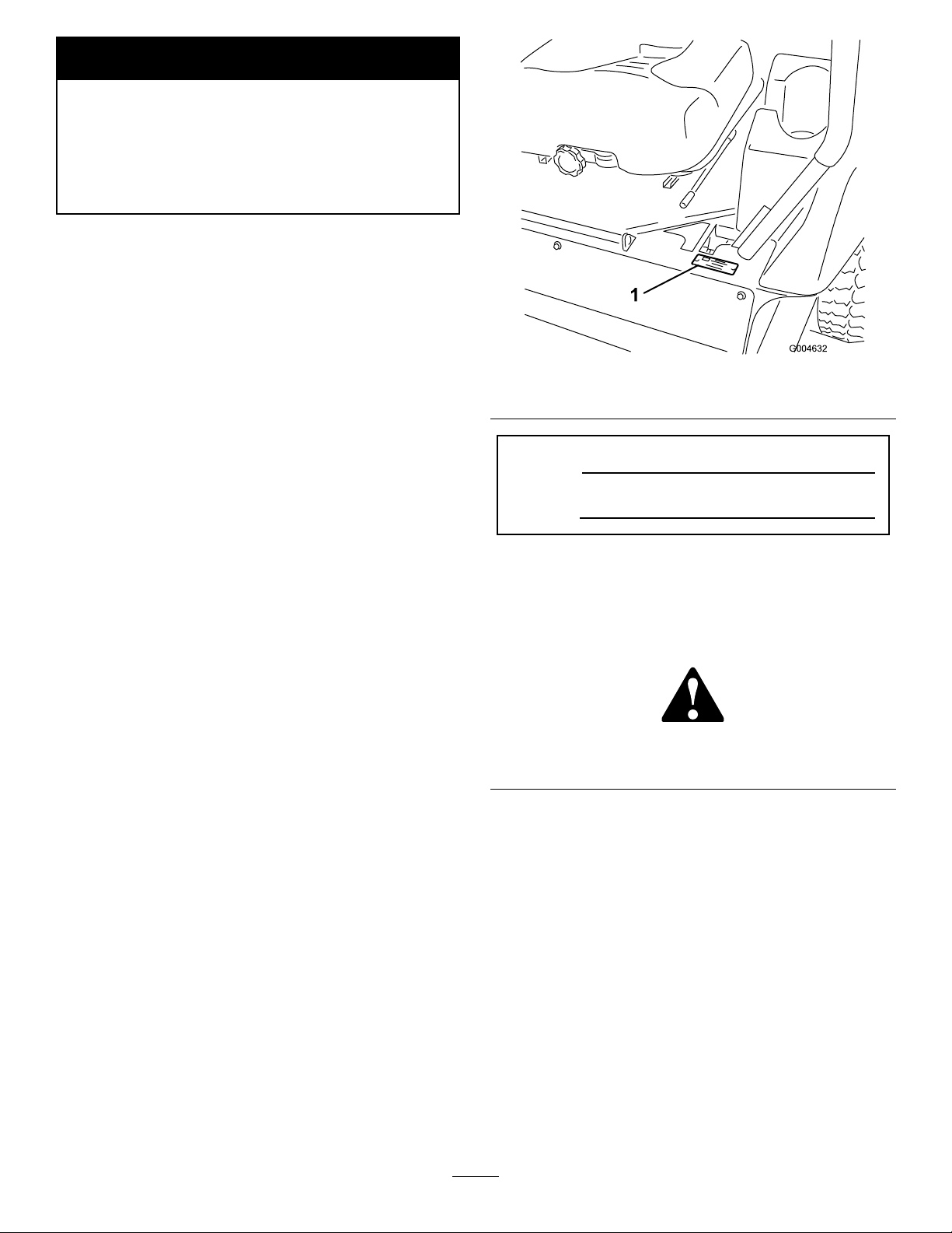
Figure1
1.Modelandserialnumberlocation
ModelNo.
SerialNo.
Thismanualidentiespotentialhazardsandhas
safetymessagesidentiedbythesafetyalertsymbol
(Figure2),whichsignalsahazardthatmaycauseserious
injuryordeathifyoudonotfollowtherecommended
precautions.
Figure2
1.Safetyalertsymbol
Wheneveryouneedservice,genuineToroparts,or
additionalinformation,contactanAuthorizedService
DealerorToroCustomerServiceandhavethemodel
andserialnumbersofyourproductready .Figure1
identiesthelocationofthemodelandserialnumbers
ontheproduct.Writethenumbersinthespace
provided.
©2008—TheT oro®Company
8111LyndaleAvenueSouth
Bloomington,MN55420
Thismanualalsouses2wordstohighlightinformation.
Importantcallsattentiontospecialmechanical
informationandNoteemphasizesgeneralinformation
worthyofspecialattention.
Contactusatwww.T oro.com.
2
PrintedintheUSA.
AllRightsReserved
Page 3

Contents
Introduction.................................................................2
Safety...........................................................................4
SafeOperatingPractices.......................................4
ToroRidingMowerSafety....................................5
SoundPressureLevel...........................................6
SoundPowerLevel...............................................6
VibrationLevel.....................................................6
SlopeChart..........................................................7
SafetyandInstructionalDecals.............................8
Setup..........................................................................14
1InstallingtheLeftRearTire(Model30464TC
and30363TCOnly)........................................14
2ActivatingandChargingtheBattery(Model
30464TCand30363TCOnly).........................14
3AdjustingtheROPS.........................................16
4CheckingtheTirePressure...............................16
5InstallingW eights(ForCECompliance)...........17
6CheckingFluidLevels......................................17
7ReadingtheManualsandViewingthe
TrainingMaterials...........................................17
ProductOverview......................................................18
Controls.............................................................18
Specications.....................................................20
Attachments/Accessories...................................20
Operation...................................................................21
AddingFuel.......................................................21
FillingtheFuelTank...........................................22
CheckingtheEngineOilLevel............................22
CheckingtheCoolingSystem..............................22
CheckingtheHydraulicSystem...........................22
UsingtheRolloverProtectionSystem
(ROPS)..........................................................22
ThinkSafetyFirst...............................................23
OperatingtheParkingBrake...............................24
StartingandStoppingtheEngine........................25
DrivingtheMachine...........................................26
StoppingtheMachine.........................................26
OperatingtheMower.........................................27
AdjustingtheHeight-of-Cut...............................28
AdjustingtheSkids.............................................28
AdjustingtheRearAnti-ScalpRollers..................29
AdjustingtheRollers..........................................29
TheSafetyInterlockSystem................................31
PositioningtheSeat............................................32
UnlatchingtheSeat.............................................33
PushingtheMachinebyHand.............................33
LoadingMachines..............................................34
TransportingMachines.......................................35
OperatingTips...................................................35
Maintenance...............................................................37
RecommendedMaintenanceSchedule(s)................37
DailyMaintenanceChecklist...............................38
Lubrication.............................................................39
GreasingtheBearingsandBushings....................39
ServicingtheMowerDeckGearBox
Lubricant.......................................................41
EngineMaintenance...............................................43
AirCleanerMaintenance....................................43
ServicingtheEngineOil.....................................43
FuelSystemMaintenance.......................................45
ServicingtheW aterSeparator.............................45
CleaningtheFuelTank.......................................45
FuelLinesandConnections................................45
BleedingtheFuelSystem....................................45
BleedingAirFromtheInjectors..........................46
ElectricalSystemMaintenance................................47
ServicingtheBattery...........................................47
StoringtheBattery..............................................47
CheckingtheFuses.............................................47
DriveSystemMaintenance.....................................48
CheckingtheTirePressure.................................48
ReplacingtheCastorWheelsand
Bearings.........................................................48
CoolingSystemMaintenance..................................49
CheckingtheCoolingSystem.............................49
CleaningtheRadiator.........................................50
BrakeMaintenance.................................................51
AdjustingtheParkingBrakeInterlock
Switch............................................................51
BeltMaintenance....................................................52
CheckingtheAlternatorBelt..............................52
ReplacingtheBladeDriveBelts..........................52
ControlsSystemMaintenance.................................53
AdjustingtheControlLeverNeutralInterlock
Switch............................................................53
AdjustingtheControlLeverNeutral
Return............................................................53
AdjustingtheTractionDriveforNeutral.............54
AdjustingtheMaximumGroundSpeed..............55
AdjustingtheTracking........................................56
HydraulicSystemMaintenance...............................57
CheckingtheHydraulicSystem...........................57
ChangingtheHydraulicOilAndFilter................58
MowerDeckMaintenance......................................59
ServicingtheCuttingBlades...............................59
CorrectingMowerDeckMismatch.....................61
AdjustingtheMowerDeckPitch.........................62
ReplacingtheGrassDeector.............................62
Cleaning.................................................................63
CleaningUndertheMower.................................63
WasteDisposal...................................................63
Storage.......................................................................64
Machine.............................................................64
Engine...............................................................64
Schematics.................................................................65
3
Page 4

Safety
Machineswithmodelnumbers30360TE,30461,30462,
30363TC,30363TE,30464,30465,or30464TCmeet
orexceedCENstandardEN836:1997andANSI
B71.4-2004specicationsineffectatthetimeof
production.Machineswithmodelnumbers30360and
30363meetorexceedANSIB71.4–2004specications
ineffectatthetimeofproduction
Improperuseormaintenancebytheoperatoror
ownercanresultininjury.Toreducethepotential
forinjury,complywiththesesafetyinstructionsand
alwayspayattentiontothesafetyalertsymbol,which
meansCaution,Warning,orDanger—personalsafety
instruction.Failuretocomplywiththeinstructionmay
resultinpersonalinjuryordeath.
SafeOperatingPractices
ThefollowinginstructionsarefromtheCENstandard
EN836:1997andANSIB71.4-2004.
Thisproductiscapableofamputatinghandsand
feetandthrowingobjects.Alwaysfollowallsafety
instructionstoavoidseriousinjuryordeath.
Training
•ReadtheOperator’sManualandothertrainingmaterial
carefully.Befamiliarwiththecontrols,safetysigns,
andtheproperuseoftheequipment.
•Neverallowchildrenorpeopleunfamiliarwith
theseinstructionstousethelawnmower.Local
regulationscanrestricttheageoftheoperator.
•Nevermowwhilepeople,especiallychildren,orpets
arenearby .
•Keepinmindthattheoperatororuserisresponsible
foraccidentsorhazardsoccurringtootherpeopleor
theirproperty.
•Donotcarrypassengers.
•Alldriversshouldseekandobtainprofessional
andpracticalinstruction.Suchinstructionshould
emphasize:
–theneedforcareandconcentrationwhen
workingwithride-onmachines;
–controlofaride-onmachineslidingonaslope
willnotberegainedbytheapplicationofthe
controllevers.Themainreasonsforlossof
controlare:
◊insufcientwheelgrip,especiallyonwet
grass;
◊beingdriventoofast;
◊inadequatebraking;
◊thetypeofmachineisunsuitableforitstask;
◊lackofawarenessoftheeffectofground
conditions,especiallyslopes;
◊incorrectloaddistribution.
Preparation
•Whilemowing,alwayswearsubstantialfootwearand
longtrousers.Donotoperatetheequipmentwhen
barefootorwearingopensandals.
•Thoroughlyinspecttheareawheretheequipment
istobeusedandremoveallobjectswhichmaybe
thrownbythemachine.
•Warning—fuelishighlyammable.
–Storefuelincontainersspecicallydesignedfor
thispurpose.
–Refueloutdoorsonlyanddonotsmokewhile
refueling.
–Addfuelbeforestartingtheengine.Never
removethecapofthefueltankoraddfuelwhile
theengineisrunningorwhentheengineishot.
–Iffuelisspilled,donotattempttostartthe
enginebutmovethemachineawayfromthe
areaofspillageandavoidcreatinganysourceof
ignitionuntilfuelvaporshavedissipated.
–Replaceallfueltankandcontainercapssecurely.
•Replacefaultysilencers/mufers.
•Beforeusing,alwaysvisuallyinspecttoseethatthe
blades,bladeboltsandcutterassemblyarenotworn
ordamaged.Replacewornordamagedbladesand
boltsinsetstopreservebalance.
•Onmulti-bladedmachines,takecareasrotatingone
bladecancauseotherbladestorotate.
Operation
•Bealert,slowdownandusecautionwhenmaking
turns.Lookbehindandtothesidebeforechanging
directions.
•Donotoperatetheengineinaconnedspacewhere
dangerouscarbonmonoxidefumescancollect.
•Mowonlyindaylightoringoodarticiallight.
•Beforeattemptingtostarttheengine,disengageall
bladeattachmentclutchesandshiftintoneutral.
•Rememberthereisnosuchthingasasafeslope.
Travelongrassslopesrequiresparticularcare.To
guardagainstoverturning:
4
Page 5

–donotstoporstartsuddenlywhenonaslope;
•Replacewornordamagedpartsforsafety .
–useslowspeedsonslopesandduringtightturns;
–stayalertforhumpsandhollowsandother
hiddenhazards;
•Watchoutfortrafcwhencrossingornearroadways.
•Stopthebladesfromrotatingbeforecrossing
surfacesotherthangrass.
•Whenusinganyattachments,neverdirectdischarge
ofmaterialtowardbystandersnorallowanyonenear
themachinewhileinoperation.
•Neveroperatethemachinewithdamagedguards,
shields,orwithoutsafetyprotectivedevicesinplace.
•Donotchangetheenginegovernorsettingsor
overspeedtheengine.Operatingtheengineat
excessivespeedmayincreasethehazardofpersonal
injury.
•Beforeleavingtheoperator’sposition:
–disengagethepowertake-offandlowerthe
attachments;
–changeintoneutralandsettheparkingbrake;
–stoptheengineandremovethekey.
•Disengagedrivetoattachments,stoptheengine,and
removetheignitionkey:
–beforeclearingblockagesoruncloggingchute;
–beforechecking,cleaningorworkingonthelawn
mower;
–afterstrikingaforeignobject.Inspectthelawn
mowerfordamageandmakerepairsbefore
restartingandoperatingtheequipment;
–ifthemachinestartstovibrateabnormally(check
immediately).
•Disengagedrivetoattachmentswhentransporting
ornotinuse.
•Stoptheengineanddisengagedrivetoattachment
beforerefuelling.
MaintenanceandStorage
•Keepallnuts,boltsandscrewstighttobesurethe
equipmentisinsafeworkingcondition.
•Neverstoretheequipmentwithfuelinthetank
insideabuildingwherefumesmayreachanopen
ameorspark.
•Allowtheenginetocoolbeforestoringinany
enclosure.
•Toreducetherehazard,keeptheengine,
silencer/mufer,batterycompartmentandfuel
storageareafreeofgrass,leaves,orexcessivegrease.
•Ifthefueltankhastobedrained,dothisoutdoors.
•Onmulti-bladedmowers,takecareasmanually
rotatingonebladecancauseotherbladestorotate.
•Whenmachineistobeparked,storedorleft
unattended,lowerthemowerdeck.
ToroRidingMowerSafety
Thefollowinglistcontainssafetyinformationspecicto
Toroproductsorothersafetyinformationthatyoumust
knowthatisnotincludedintheCENstandard.
•Engineexhaustcontainscarbonmonoxide,whichis
anodorless,deadlypoisonthatcankillyou.Donot
runengineindoorsorinanenclosedarea.
•Keephands,feet,hairandlooseclothingawayfrom
attachmentdischargearea,undersideofmowerand
anymovingpartswhileengineisrunning.
•Donottouchequipmentorattachmentpartswhich
maybehotfromoperation.Allowtocoolbefore
attemptingtomaintain,adjust,orservice.
•Batteryacidispoisonousandcancauseburns.Avoid
contactwithskin,eyesandclothing.Protectyour
face,eyes,andclothingwhenworkingwithabattery.
•Thismachineisnotdesignedorequippedfor
on-roaduseandisa“slow-movingvehicle.”Ifyou
mustcrossortravelonapublicroad,youshould
beawareofandcomplywithlocalregulations,such
asrequiredlights,slowmovingvehiclesigns,and
reectors.
•Batterygasescanexplode.Keepcigarettes,sparks
andamesawayfrombattery.
•UseonlygenuineTororeplacementpartstoensure
thatoriginalstandardsaremaintained.
•UseonlyToroapprovedattachments.Warrantymay
bevoidedifusedwithunapprovedattachments.
SlopeOperation
•Donotmowneardrop-offs,ditches,steepbanks
orwater.Wheelsdroppingoveredgescancause
rollovers,whichmayresultinseriousinjury,death,
ordrowning.
•Donotmowslopeswhengrassiswet.Slippery
conditionsreducetractionandcouldcausesliding
andlossofcontrol.
•Donotmakesuddenturnsorrapidspeedchanges.
•Useawalkbehindmowerand/orahandtrimmer
neardrop-offs,ditches,steepbanksorwater.
•Reducespeedanduseextremecautiononslopes.
5
Page 6

•Removeormarkobstaclessuchasrocks,treelimbs,
etc.fromthemowingarea.Tallgrasscanhide
obstacles.
•Watchforditches,holes,rocks,dips,andrisesthat
changetheoperatingangle,asroughterraincould
overturnthemachine.
•Avoidsuddenstartswhenmowinguphillbecause
themowermaytipbackwards.
•Beawarethatlossoftractionmayoccurgoing
downhill.Weighttransfertothefrontwheelsmay
causedrivewheelstoslipandcauselossofbraking
andsteering.
•Alwaysavoidsuddenstartingorstoppingona
slope.Iftireslosetraction,disengagethebladesand
proceedslowlyofftheslope.
•Followthemanufacturer’srecommendationsfor
wheelweightsorcounterweightstoimprovestability.
SoundPressureLevel
Note:Thedatacontainedinthissectiononlypertains
tounitsmarkedwiththeCElogo().
ThisunithasanequivalentcontinuousA-weighted
soundpressurelevelattheoperatorearof90dBA,based
onmeasurementsofidenticalmachinesperEN11201.
SoundPowerLevel
Note:Thedatacontainedinthissectiononlypertains
tounitsmarkedwiththeCElogo().
Thisunithasaguaranteedsoundpowerlevelof105
dBA,basedonmeasurementsofidenticalmachinesper
EN11094.
VibrationLevel
•Useextremecarewithattachments.Thesecan
changethestabilityofthemachineandcauseloss
ofcontrol.
UsingtheRolloverProtectionSystem
(ROPS)
•Keeptherollbarintheraisedandlockedposition
andusetheseatbeltwhenoperatingthemachine.
•Becertainthattheseatbeltcanbereleasedquickly
intheeventofanemergency.
•Beawarethereisnorolloverprotectionwhenthe
rollbarisdown.
•Checktheareatobemowedandneverfoldthe
ROPSinareaswherethereareslopes,dropoffsor
water.
•Lowertherollbaronlywhenabsolutelynecessary.
Donotweartheseatbeltwiththerollbarfolded
down.
•Checkcarefullyforoverheadclearances(i.e.
branches,doorways,electricalwires)beforedriving
underanyobjectsanddonotcontactthem.
Hand-Arm
Thisunitdoesnotexceedahand/armvibrationlevelof
2.5m/s
perEN1033.
2
,basedonmeasurementsofidenticalmachines
WholeBody
Thisunitdoesnotexceedawholebodyvibration
levelof0.5m/s
machinesperEN1032.
2
,basedonmeasurementsofidentical
6
Page 7
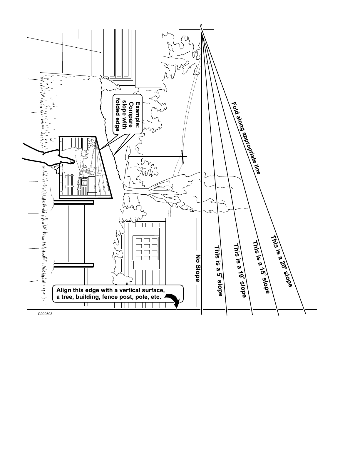
SlopeChart7SafetyandInstructional
Decals
Page 8
Safetydecalsandinstructionsareeasilyvisibletotheoperatorandarelocatednearanyareaof
potentialdanger.Replaceanydecalthatisdamagedorlost.
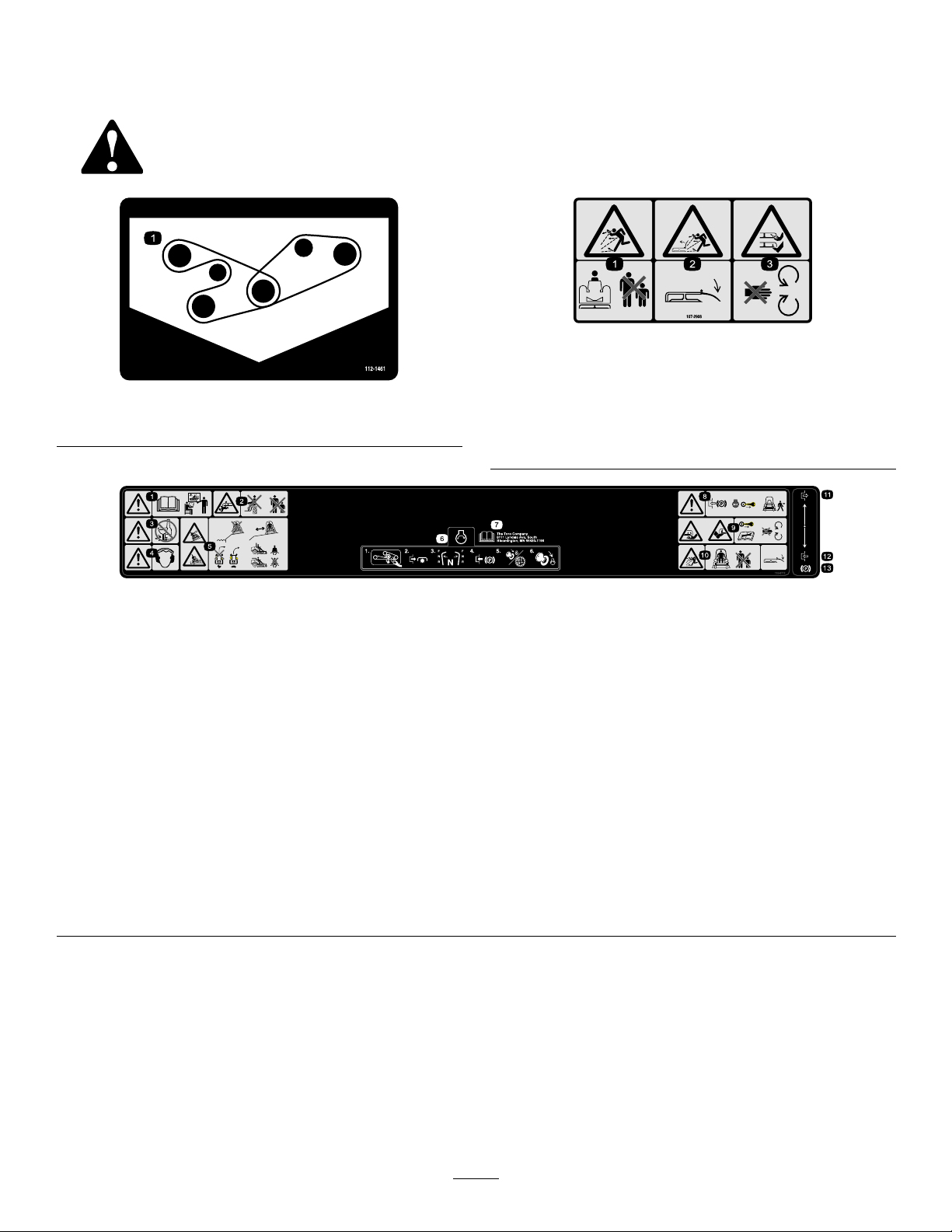
107-2908
1.Thrownobjecthazard—keepbystandersasafedistance
fromthemachine.
112-1461
1.Beltrouting
2.Thrownobjecthazard—donotoperatethemowerwiththe
deectoruporremoved,keepthedeectorinplace.
3.Cutting/dismembermenthazardofhandorfoot,mower
blade—stayawayfrommovingparts.
1.Warning—readtheOperator’sManualandreceivetraining.
2.Crushing/dismembermenthazardofbystanders—donot
carrypassengers,keepbystandersasafedistancefromthe
machine.
3.Warning—donotusedrugsoralcohol.
4.Warning—wearhearingprotection.11.Disengage
5.Tipping,dropoffhazard—donotoperatenearwaterdrop-offs,
stayasafedistancefromdrop-offs,slowmachinebefore
turning,donotturnathighspeeds,wearaseatbeltwhen
aROPSisinplace,donotwearaseatbeltwhenROPSis
lowered.
6.Tostarttheengine:clearanydebrisfrommowerbelt,
disengagethePTO,movethemotioncontrolleverstothe
neutralposition,engagetheparkingbrake,turntheignitionto
Runandwaitfortheglowpluglighttoturnoff,turntheignition
keytoStart.
7.ReadtheOperator’sManual.
110-9772
8.Warning—engagetheparkingbrake,stoptheengineand
removetheignitionkeybeforeleavingthemachine.
9.Cuttinghazardofhandorfoot—removetheignitionkey
andreadtheinstructionsbeforeservicingorperforming
maintenance,keepawayfrommovingparts.
10.Thrownobjecthazard—keepbystandersasafedistancefrom
themachine;keepalldeectorsandshieldsinplace.
12.Engage
13.Parkingbrake
8
Page 9
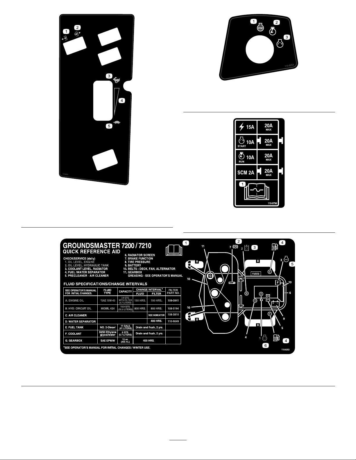
110-8253
1.PTO–Off4.Continuousvariable
setting
2.PTO—On5.Slow
3.Fast
110-8254
1.Engine–Stop3.Engine—Start
2.Engine—Run
110-9796
1.ReadtheOperator’sManualforinformationonfuses.
110-8252
1.ReadtheOperator’sManual.
2.Parkingbrake4.Fuel6.Engineoil
3.Hydraulicoil5.Enginecoolant
9
Page 10
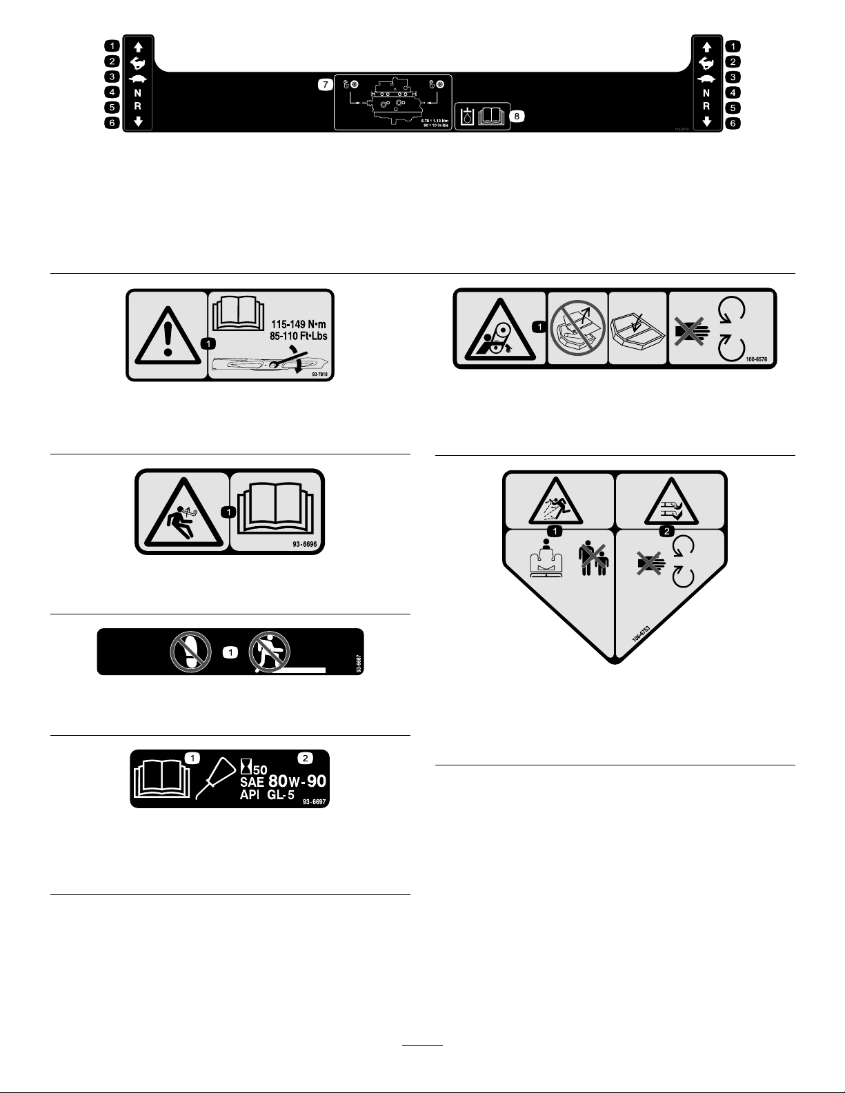
1.Forward
2.Fast4.Neutral6.Backward
3.Slow
110-9774
5.Reverse7.Towvalvelocation;torque
thetowvalvesto6.78±
1.13N⋅m(60±10in-lbs).
8.ReadtheOperator’s
Manualformore
informationonthehydraulic
oil.
93-7818
1.Warning—readtheOperator’sManualforinstructionson
torquingthebladebolt/nutto1 15-149N•m(85-110ft-lb).
93-6696
1.Storedenergyhazard—readtheOperator’sManual.
93-6687
1.Donotstephere.
100-6578
1.Entanglementhazard,belt—donotoperatethemachine
withtheshieldsorguardsremoved;alwayskeepthe
shieldsandguardsinplace;stayawayfrommovingparts.
106-6753
1.Thrownobjecthazard—keepbystandersasafedistance
fromthemachine.
2.Cutting/dismembermenthazardofhandorfoot,mower
blade—stayawayfrommovingparts.
1.ReadtheOperator’s
Manual.
93-6697
2.Checktheoilevery50
hours.AddSAE80w-90
(APIGL-5)oilifneeded.
10
Page 11

106-6755
1.Enginecoolantunder
pressure.
2.Explosionhazard—read
theOperator’sManual.
106-9206
1.Wheeltorquespecications
2.ReadtheOperator’sManual.
3.Warning—donottouch
thehotsurface.
4.Warning—readthe
Operator’sManual.
107-3069
1.Warning—thereisnorolloverprotectionwhentherollbaris
down.
2.Toavoidinjuryordeathfromarolloveraccident,keepthe
rollbarintheraisedandlockedpositionandweartheseat
belt.Lowertherollbaronlywhenabsolutelynecessary;do
notweartheseatbeltwhentherollbarisdown.
3.ReadtheOperator’sManual;driveslowlyandcarefully.
1.Removetheignitionkeyandreadthe
Operator’sManualbeforeservicingor
performingmaintenance.
107-2916
SideDischargeModelsOnly
2.Thrownobjecthazard—donotoperate
themowerwiththedeectorupor
removed,keepthedeectorinplace;
keepbystandersasafedistancefrom
themachine.
11
3.Cutting/dismembermenthazardof
handorfoot,mowerblade—stayaway
frommovingparts.
Page 12
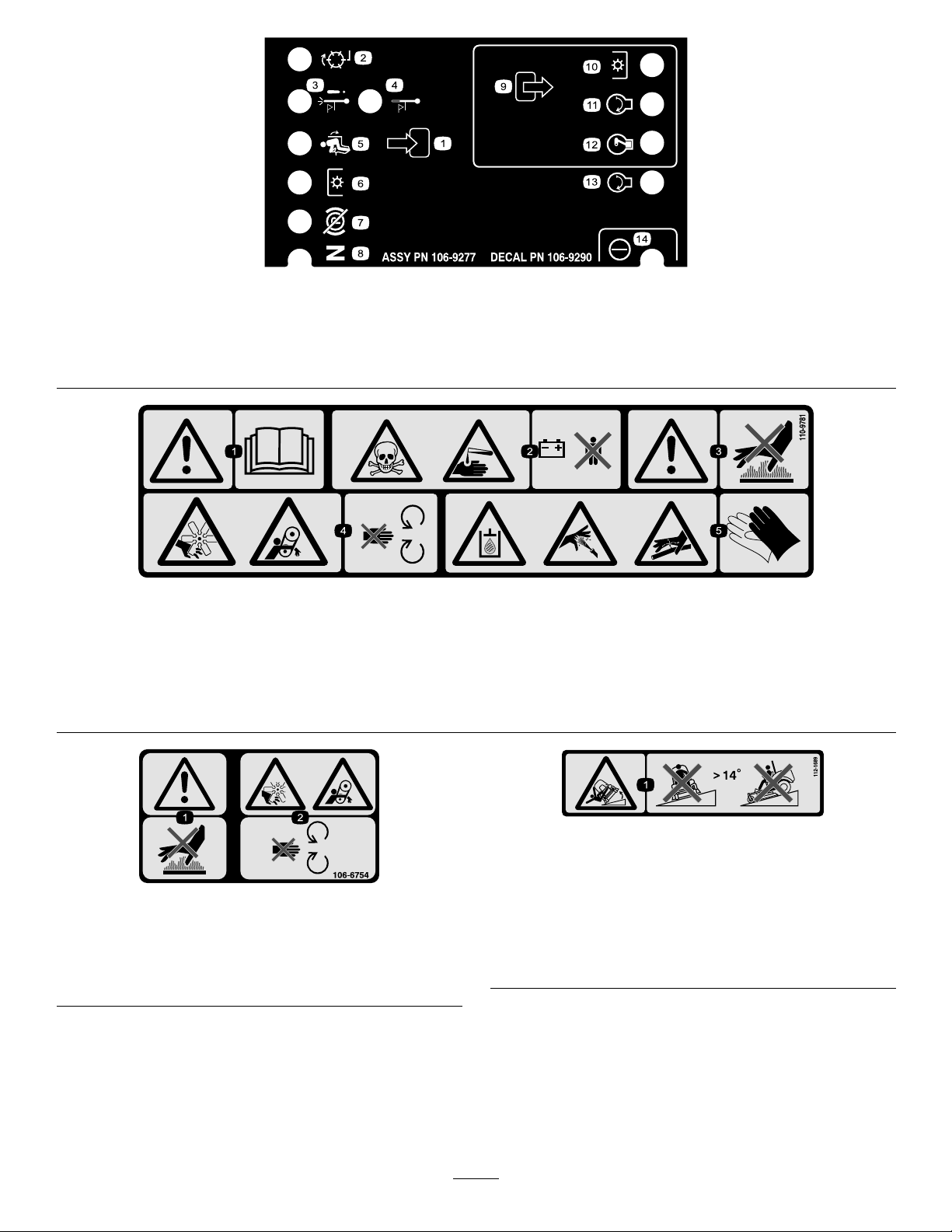
106-9290
1.Inputs5.Inseat
2.(notactiveonthismachine)6.PowerTake-off(PTO)10.PowerT ake-off(PTO)
3.Hightemperatureshutdown
7.ParkingbrakeOff11.Start
4.Hightemperaturewarning8.Neutral
9.Outputs13.Start
12.EnergizetoRun(ETR)
110-9781
1.Warning—readtheOperator’sManual.
2.Poisonandcausticliquid/chemicalburnhazard—keepchildrenasafedistancefromthebattery.
3.Warning—donottouchthehotsurface.
4.Cutting/dismembermenthazard,fanandentanglementhazard,belt—stayawayfrommovingparts.
5.Hydraulicoilinsystemunderpressure,escapinghydraulicoilpenetratingskinhazard,brokenhydrauliclineshazard—wear
protectivehandprotectionwhenhandlinghydraulicsystemcomponents.
14.Power
106-6754
CEMarkedModelsOnly(WiththeCEKitInstalled)
1.Warning—donottouchthehotsurface.
2.Cutting/dismembermenthazard,fanandentanglement
hazard,belt—stayawayfrommovingparts.
112-1689
CEMarkedModelsOnly(WiththeCEKitInstalled)
*Thissafetydecalincludesaslopewarningrequiredonthemachineforcompliance
totheEuropeanLawnMowerSafetyStandardEN836:1997.Theconservative
maximumslopeanglesindicatedforoperationofthismachineareprescribedby
andrequiredbythisstandard.
1.Tippinghazard—donotoperateonslopesgreaterthan14
degrees.
12
Page 13
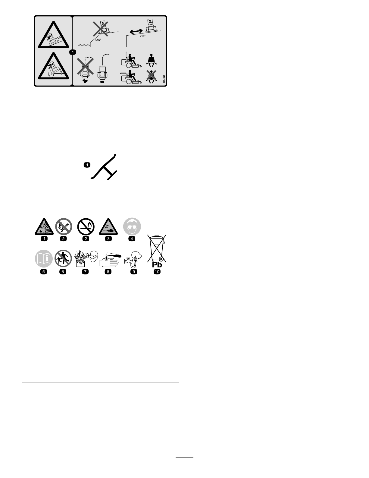
107-1866
1.Slidingandlossofcontrolhazardandtippinghazard,
drop-offs—donotoperatethemachineneardrop-offs,
slopesgreaterthan15degrees,orwater;keepasafe
distancefromdrop-offs;donotturnsharplywhiletraveling
fast,instead,slowdownandturngradually;iftherollbar
israised,weartheseatbelt;iftherollbarislowered,do
notweartheseatbelt.
Manufacturer’sMark
1.Indicatesthebladeisidentiedasapartfromtheoriginal
machinemanufacturer.
BatterySymbols
Someorallofthesesymbolsareonyourbattery
1.Explosionhazard
2.Nore,opename,or
smoking.
3.Causticliquid/chemical
burnhazard
4.Weareyeprotection9.Flusheyesimmediately
5.ReadtheOperator’s
Manual.
6.Keepbystandersasafe
7.Weareyeprotection;
8.Batteryacidcancause
10.Containslead;donot
distancefromthebattery.
explosivegasescan
causeblindnessandother
injuries
blindnessorsevereburns.
withwaterandgetmedical
helpfast.
discard.
13
Page 14

Setup
LooseParts
Usethechartbelowtoverifythatallpartshavebeenshipped.
ProcedureDescription
1
2
3
4
5
6
7
Tire1
Nopartsrequired
Nopartsrequired
Nopartsrequired
Nopartsrequired
Nopartsrequired
Operator’sManual
EngineOperator’sManual
PartsCatalog
OperatorTrainingMaterial
Pre-deliveryInspectionSheet
Enginewarranty1
CEcerticate
Qty.
Use
Installtheleftreartire(model30464TC
and30363TConly).
–
–
–
–
–
1
1
1
1
1
1
Activateandchargethebattery(model
30464TCand30363TConly).
AdjusttheROPS.
Checkthetirepressure.
Installweights.
Checkthehydraulicuid,engineoil,
andcoolantlevels.
Readthemanualsandviewthe
trainingmaterialsbeforeoperatingthe
machine.Usetheremainingpartsfor
theinstallationofattachments.
1
InstallingtheLeftRearTire
(Model30464TCand30363TC
Only)
Partsneededforthisprocedure:
1Tire
Procedure
1.Supporttheleftrearofthemachinewithjackstands.
2.Removethelugnutsfromthetiremountingstuds.
3.Pullthecrateandbracketoffofthewheelhub.
4.Installthereartireontothehubandsecureitusing
thelugnutspreviouslyremoved.
5.Torquethelugnutsto75to80ft-lb(102to108
N⋅m).
2
ActivatingandChargingthe
Battery(Model30464TCand
30363TCOnly)
NoPartsRequired
Procedure
Useonlyelectrolyte(1.265SpecicGravity)toll
batteryinitially.
1.Removethebatteryfromthemachine.
Important:Donotaddelectrolytewhilethe
batteryisinthemachine.Youcouldspillit,
causingcorrosion.
2.Cleanthetopofthebatteryandremovethevent
caps(Figure3).
14
Page 15
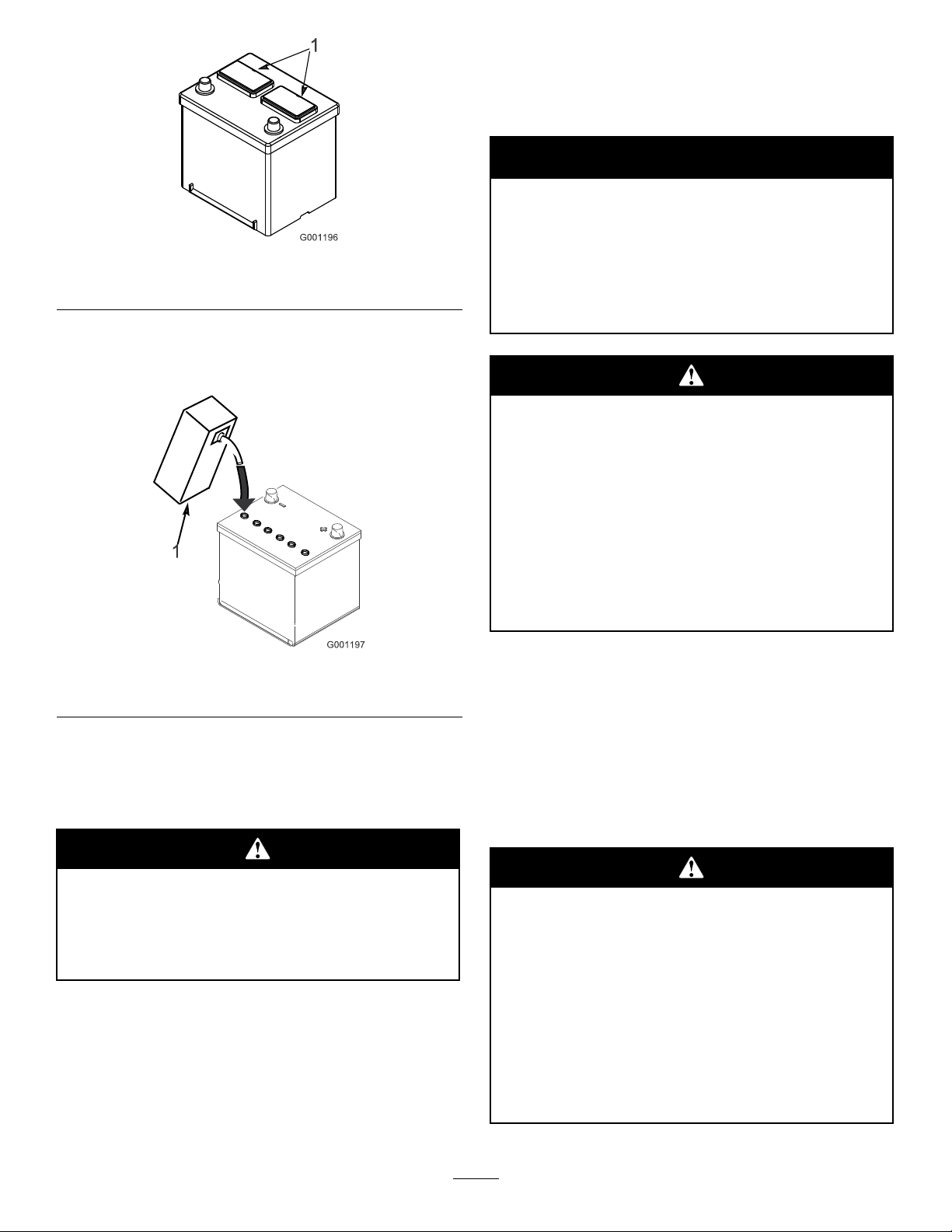
Figure3
1.Ventcaps
3.Carefullylleachcellwithelectrolyteuntiltheplates
arecoveredwithabout1/4inch(6mm)ofuid
(Figure4).
Note:Afterthebatteryhasbeenactivated,add
onlydistilledwatertoreplacenormalloss,although
maintenance-freebatteriesshouldnotrequirewater
undernormaloperatingconditions.
Warning
CALIFORNIA
Proposition65Warning
Batteryposts,terminals,andrelated
accessoriescontainleadandleadcompounds,
chemicalsknowntotheStateofCalifornia
tocausecancerandreproductiveharm.
Washhandsafterhandling.
Batteryterminalsormetaltoolscouldshort
againstmetaltractorcomponentscausing
sparks.Sparkscancausethebatterygassesto
explode,resultinginpersonalinjury.
Figure4
1.Electrolyte
4.Allowapproximately20to30minutesforthe
electrolytetosoakintotheplates.Rellasnecessary
tobringtheelectrolytetowithinabout1/4inch(6
mm)ofthebottomofthellwell(Figure4).
Chargingthebatteryproducesgassesthatcan
explode.
Neversmokenearthebatteryandkeepsparks
andamesawayfrombattery.
•Whenremovingorinstallingthebattery,do
notallowthebatteryterminalstotouchany
metalpartsofthetractor.
•Donotallowmetaltoolstoshortbetween
thebatteryterminalsandmetalpartsofthe
tractor.
7.Installthebatteryintothemachineandsecureit.
Important:Thebatterymustnotbeableto
moveorwigglewhenpushed.
8.First,installthepositivecable(red)tothepositive
(+)terminalandthenthenegativecable(black)to
thenegative(-)terminalofthebattery.Slidethe
rubberbootoverthepositiveterminaltopreventa
possibleshortfromoccurring.
Incorrectbatterycableroutingcoulddamage
themachineandcablescausingsparks.Sparks
cancausethebatterygassestoexplode,
resultinginpersonalinjury.
5.Connecta3to4ampbatterychargertothebattery
posts.Chargethebatteryatarateof3to4amps
untilthespecicgravityis1.250orhigherandthe
temperatureisatleast60°F.(16°C)withallcells
gasingfreely.
6.Whenthebatteryischarged,disconnectthecharger
fromtheelectricaloutletandbatteryposts.
•Alwaysdisconnectthenegative(black)
batterycablebeforedisconnectingthe
positive(red)cable.
•Alwaysconnectthepositive(red)battery
cablebeforeconnectingthenegative(black)
cable.
15
Page 16
Connectingcablestothewrongpostcould
damagetheelectricalsystemandresultin
personalinjury.
4
CheckingtheTirePressure
Note:Ensurethatthebatterycablesarerouted
awayfromanysharpedgesormovingparts.
3
AdjustingtheROPS
NoPartsRequired
Procedure
1.Removethehairpincotterpinsandremovethetwo
pinsfromtherollbar(Figure5).
NoPartsRequired
Procedure
Thetiresareoverinatedforshipping.Therefore,
releasesomeoftheairtoreducethepressure.The
correctairpressureis15psi(103kPa)inthereartires
and25psi(172kPa)inthecasterwheels.
Figure5
RightSideShown
1.Rollbar3.Hairpincotterpin
2.Pin
2.Raisetherollbartotheuprightpositionandinstall
thetwopinsandsecurethemwiththehairpincotter
pins(Figure5).
Note:Ifyoumustlowertherollbar,pushthebar
forwardtorelievepressureonthepins,removethe
pins,lowerthebarslowly,andsecureitwiththepins
sothatitdoesnotdamagethehood.
16
Page 17

5
InstallingWeights(ForCECompliance)
NoPartsRequired
Procedure
Machineswith72inchdecksinstalledandnootherattachments,donotneedaddedweighttomeetCEstandards.
However,youmayneedtopurchaseandinstalladditionalweightdependingonmowerdecksize/typeandthe
attachmentsyouinstallonthemachine.Thefollowingtableliststhevariousattachmentcongurationsandthe
additionalfrontweightneededforeachmodel:
AttachmentConguration
Groundsmaster7200/7210
TractionUnitwithnoAdded
Attachments
Groundsmaster7200/7210
TractionUnitandHardCanopy
Groundsmaster7200/7210
TractionUnit,HardCanopy,and
RoadLightKit
Groundsmaster7200/7210
TractionUnit,HardCanopy,
RoadLightKit,andJackStand
Groundsmaster7200/7210
TractionUnit,HardCanopy,and
JackStand
Groundsmaster7200/7210
TractionUnit,RoadLightKit,
andJackStand
Groundsmaster7200/7210
TractionUnitandRoadLightKit
Groundsmaster7200/7210
TractionUnitandJackStand
WeightRequiredwitha62
inch(157.5cm)Guardian
Mower
22lb(10kg)0lb(0kg)0lb(0kg)
75lb(34kg)21lb(9.5kg)33lb(15kg)
71lb(32.2kg)63lb(28.5kg)22lb(10kg)
40lb(18kg)37lb(17kg)22lb(10kg)
31lb(14kg)22lb(10kg)22lb(10kg)
0lb(0kg)0lb(0kg)0lb(0kg)
25lb(11.3kg)0lb(0kg)0lb(0kg)
0lb(0kg)0lb(0kg)0lb(0kg)
WeightRequiredwitha72
inch(183cm)Guardian
Mower
inch(183cm)Side-discharge
WeightRequiredwitha72
Mower
ContactyourAuthorizedToroDistributortoobtaintheappropriatekitsandweightsforyourmachine.
2.Checktheengineoillevelbeforeandafterstarting
theengine,refertoCheckingtheEngineOilLevel
6
in,page.
3.Checkthecoolingsystembeforestartingtheengine;
CheckingFluidLevels
refertoCheckingtheCoolingSystemin,page
NoPartsRequired
Procedure
1.Checkthehydraulicuidlevelbeforestartingthe
engine,refertoCheckingtheHydraulicFluidLevel
in,page.
17
Page 18
7
ReadingtheManualsand
ViewingtheTrainingMaterials
Partsneededforthisprocedure:
1
Operator’sManual
1
EngineOperator’sManual
1
PartsCatalog
1
OperatorTrainingMaterial
1
Pre-deliveryInspectionSheet
1Enginewarranty
1
CEcerticate
Procedure
1.Readthemanuals.
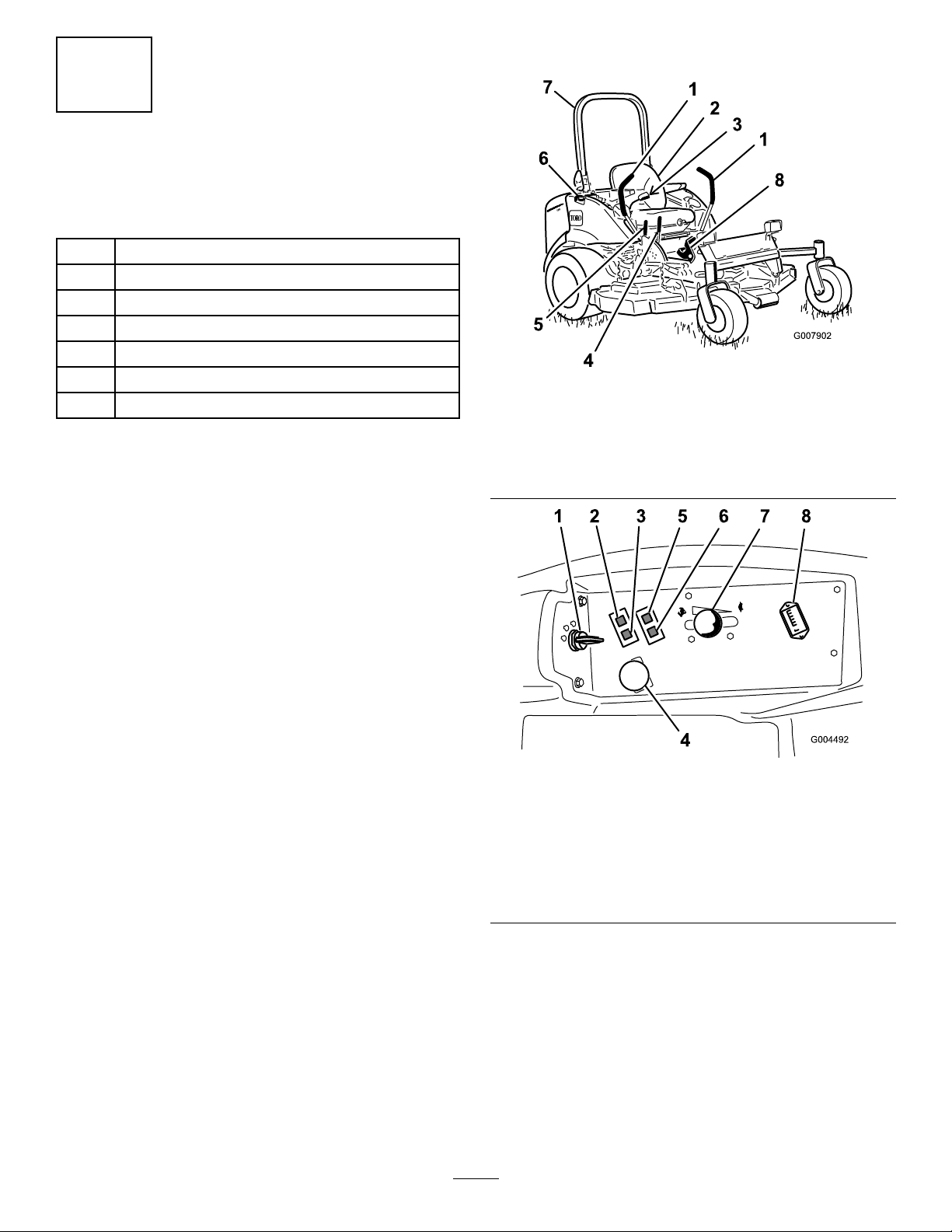
ProductOverview
Figure6
1.Motioncontrollever
2.Seat6.Fuelcap(bothsides)
3.Seatbelt
4.Parkingbrakelever
5.Mowerdeckliftlever
7.Rollbar
8.Footoperatedmowerlift
pedal
2.Viewtheoperatortrainingmaterials.
1.Ignitionswitch
2.Enginecoolant
temperaturewarning
light
3.Glowpluglight
4.Powertakeoff(PTO)
Switch
Controls
Figure7
5.Oilpressurewarninglight
6.Chargeindicatorlight
7.Throttlelever
8.Hourmeter
Becomefamiliarwithallthecontrolsbeforeyoustartthe
engineandoperatethemachine(Figure6andFigure7).
MotionControlLevers
Themotioncontrolleverscontroltheforwardand
rearwardmotionsaswellastheturningofthemachine.
RefertoDrivingForwardorBackwardin,page.
18
Page 19
ParkingBrakeLever
Whenevertheengineisshutoff,engagetheparking
braketopreventaccidentalmovementofthemachine.
Toengagetheparkingbrake,pulltheparkingbrakelever
rearwardandup(Figure8).Toreleasetheparkingbrake,
pushtheparkingbrakeleverforwardanddown.
Figure9
1.Footoperateddeckliftlever
IgnitionSwitch
Figure8
1.Parkingbrakelever
Donotparkthetractionunitonaslope.
2.Mowerdeckliftlever
HandOperatedDeckLiftLever
Thedeckliftlever(Figure8)activatesthehydraulic
circuitthatraisesandlowersthemowerdeck.Pullback
onthelevertoraisethemowerdeckandpushforward
onittolowerit.
FootOperatedDeckLiftPedal
Thedeckliftpedal(Figure9)raisesandlowersthe
mowerdeck.Theenginemustberunningforyoutouse
thispedal.Pressdownonthetopoftheliftpedalto
raisethemowerdeckandonthebottomoftheliftpedal
tolowerthemowerdeck.
Theignitionswitchhasthreepositions:Off,
On/Preheat,andStart.
ThrottleLever
Thethrottlelevercontrolsthespeedoftheengine.
MovingthethrottleleverforwardtowardtheFast
positionincreasestheenginespeed.Movingitrearward
towardtheSlowpositiondecreasestheenginespeed.
Thethrottlecontrolsthespeedofthebladesand,in
conjunctionwithmotioncontrollevers,controlsground
speedofthemachine.Alwaysrunthemachinewiththe
throttleintheFastpositionwhencuttinggrass.
PowerTakeOff(PTO)Switch
Thepowertakeoff(PTO)switchstartsandstopsthe
mowerblades.
HourMeter
Thehourmeterrecordsthenumberofhourstheengine
hasoperated.Itoperateswhenthekeyswitchisinthe
Runposition.Usethesetimesforschedulingregular
maintenance.
GlowPlugLight(OrangeLight)
Theglowplugindicatorlightturnsonwhentheignition
switchisturnedtotheOnposition.Itremainslitfor6
seconds.Whenthelightturnsoff,theengineisready
tobestarted.
19
Page 20

EngineCoolantTemperatureWarning
Light
Thislightglowsandthecuttingbladesstopiftheengine
coolanttemperatureishigh.Ifthemachineisnot
stoppedandthecoolanttemperaturerisesanother20°
F,theenginewillstop.
Specications
Note:Specicationsanddesignaresubjecttochange
withoutnotice.
Length
Width(RearWheels)57inches(144.8cm)
97inches(246.4cm)
Important:Ifthemowerdeckshutsdownandthe
temperaturewarninglightison,pushPTOknob
down,drivetoasafeatarea,movethethrottle
levertotheSlowposition,movethemotioncontrol
leversintotheneutrallockedposition,andengage
theparkingbrake.Allowtheenginetoidlefor
severalminuteswhileitcoolstoasafelevel.Stop
theengineandcheckthecoolingsystem;referto
CheckingtheCoolingSystemin,page.
ChargeIndicator
Illuminateswhenthesystemchargingcircuit
malfunctions.
OilPressureWarningLight
Theoilpressurewarninglightglowswhentheoil
pressureinenginedropsbelowasafelevel.Iflowoil
pressureeveroccurs,stoptheengineanddeterminethe
cause.Repairthedamagebeforestartingtheengine
again.
Height(RollBarUp)72inches(182.9cm)
Height(RollBarDown)48inches(121.9cm)
Weight,Model30360,
30360TE,30363,30363TE,
30363TC
Weight,Model30461and
30464
Weight,Model30462and
30465
2230lb(101 1kg)
2206lb(1000kg)
2151lb(975kg)
Attachments/Accessories
AselectionofToroapprovedattachmentsand
accessoriesareavailableforusewiththemachineto
enhanceandexpanditscapabilities.Contactyour
AuthorizedServiceDealerorDistributororgoto
www.Toro.comforalistofallapprovedattachments
andaccessories.
FuelGauge
Thefuelgauge(Figure10)indicatesthequantityoffuel
remaininginthefueltanks.
Figure10
1.Fuelgauge
20
Page 21

Operation
petrodieselportionshouldbeloworultralowsulfur.
Observethefollowingprecautions:
Note:Determinetheleftandrightsidesofthe
machinefromthenormaloperatingposition.
Thismachineproducessoundlevelsinexcess
of85dBAattheoperatorsearandcancause
hearinglossthroughextendedperiodsof
exposure.
Wearhearingprotectionwhenoperatingthis
machine.
AddingFuel
Useonlyclean,freshdieselfuelorbiodieselfuelswith
low(<500ppm)orultralow(<15ppm)sulfurcontent.
Theminimumcetaneratingshouldbe40.Purchase
fuelinquantitiesthatcanbeusedwithin180daysto
ensurefuelfreshness.
Fueltankcapacity:11.5USgallons(43.5l)
Usesummergradedieselfuel(No.2-D)attemperatures
above20°F(-7°C)andwintergrade(No.1-Dor
No.1-D/2-Dblend)belowthattemperature.Useof
wintergradefuelatlowertemperaturesprovideslower
ashpointandcoldowcharacteristicswhichwillease
startingandreducefuellterplugging.
Useofsummergradefuelabove20°F(-7°C)will
contributetowardlongerfuelpumplifeandincreased
powercomparedtowintergradefuel.
Important:Donotusekeroseneorgasoline
insteadofdieselfuel.Failuretoobservethis
cautionwilldamagetheengine.
•Thebiodieselportionofthefuelmustmeet
specicationASTMD6751orEN14214.
•TheblendedfuelcompositionshouldmeetASTM
D975orEN590.
•Paintedsurfacesmaybedamagedbybiodiesel
blends.
•UseB5(biodieselcontentof5%)orlesserblends
incoldweather.
•Monitorseals,hoses,gasketsincontactwithfuelas
theymaybedegradedovertime.
•Fuellterpluggingmaybeexpectedforatimeafter
convertingtobiodieselblended.
•Contactyourdistributorifyouwishformore
informationonbiodiesel.
Incertainconditions,fuelisextremely
ammableandhighlyexplosive.Areor
explosionfromfuelcanburnyouandothers
andcandamageproperty.
•Fillthefueltankoutdoors,inanopenarea,
whentheengineiscold.Wipeupanyfuel
thatspills.
•Neverllthefueltankinsideanenclosed
trailer.
•Neversmokewhenhandlingfuel,andstay
awayfromanopenameorwherefuel
fumesmaybeignitedbyaspark.
•Storefuelinanapprovedcontainerandkeep
itoutofthereachofchildren.Neverbuy
morethana30-daysupplyoffuel.
Fuelisharmfulorfatalifswallowed.Long-term
exposuretovaporscancauseseriousinjuryand
illness.
•Avoidprolongedbreathingofvapors.
•Keepfaceawayfromnozzleandgastankor
conditioneropening.
•Keepfuelawayfromeyesandskin.
BiodieselReady
Thismachinecanalsouseabiodieselblendedfuel
ofuptoB20(20%biodiesel,80%petrodiesel).The
•Donotoperatewithoutentireexhaust
systeminplaceandinproperworking
condition.
21
Page 22

Incertainconditionsduringfueling,static
electricitycanbereleasedcausingaspark
whichcanignitethefuelvapors.Areor
explosionfromfuelcanburnyouandothers
andcandamageproperty.
•Alwaysplacefuelcontainersontheground
awayfromyourvehiclebeforelling.
•Donotllfuelcontainersinsideavehicle
oronatruckortrailerbedbecauseinterior
carpetsorplastictruckbedlinersmay
insulatethecontainerandslowthelossof
anystaticcharge.
•Whenpractical,removeequipmentfromthe
truckortrailerandrefueltheequipment
withitswheelsontheground.
•Ifthisisnotpossible,thenrefuelsuch
equipmentonatruckortrailerfroma
portablecontainer,ratherthanfromafuel
dispensernozzle.
•Ifafueldispensernozzlemustbeused,keep
thenozzleincontactwiththerimofthefuel
tankorcontaineropeningatalltimesuntil
fuelingiscomplete.
FillingtheFuelTank
Figure11
1.Bottomofthellerneck
5.Installthefueltankcapssecurely.Wipeupanyfuel
thatmayhavespilled.
Note:Ifpossible,llthefueltanksaftereachuse.
Thiswillminimizepossiblebuildupofcondensation
insidethefueltank.
CheckingtheEngineOilLevel
Beforeyoustarttheengineandusethemachine,check
theoillevelintheenginecrankcase;refertoChecking
OilLevelin,page
CheckingtheCoolingSystem
Beforeyoustarttheengineandusethemachine,check
thecoolingsystem;refertoCheckingtheCooling
Systemin,page
1.Parkthemachineonalevelsurface.
Important:Thefueltanksareconnected,but
thefueldoesnottransferquicklyfromonetank
totheother.Itisimportantwhenllingthat
youparkonalevelsurface.Ifyouparkonahill,
youmayinadvertentlyoverllthetanks.
2.Shuttheengineoffandsettheparkingbrake.
3.Cleanaroundeachfueltankcapandremovethecap.
Important:Donotopenthefueltankswhen
parkedonahill.Thefuelcouldspillout.
4.Addfueltobothfueltanks,untiltheleveliseven
withthebottomofthellerneck(Figure11).Do
notoverllthefueltanks.
CheckingtheHydraulic
System
Beforeyoustarttheengineandusethemachine,check
thehydraulicsystem;refertoCheckingtheHydraulic
Systemin,page
UsingtheRolloverProtection
System(ROPS)
Toavoidinjuryordeathfromrollover:keepthe
rollbarintheraisedlockedpositionanduse
theseatbelt.
Ensurethattherearpartoftheseatissecured
withtheseatlatch.
22
Page 23

Thereisnorolloverprotectionwhentherollbar
isinthedownposition.
•Lowertherollbaronlywhenabsolutely
necessary.
•Donotweartheseatbeltwhentherollbaris
inthedownposition.
•Driveslowlyandcarefully.
•Raisetherollbarassoonasclearance
permits.
•Checkcarefullyforoverheadclearances(i.e.
branches,doorways,electricalwires)before
drivingunderanyobjectsanddonotcontact
them.
Important:Lowertherollbaronlywhen
absolutelynecessary.
1.Tolowertherollbar,removethehairpincotters,
pushtherollbarforwardagainstthesprings,and
removethetwopins(Figure12).
Figure13
3.Installthetwopinsandsecurethemwiththehairpin
cotterpins(Figure12).
Important:Ensurethattherearpartofthe
seatissecuredwiththeseatlatch.
4.Toraisetherollbar,removethehairpincotterpins
andremovethetwopins(Figure12).
5.Raisetherollbartotheuprightpositionandinstall
thetwopinsandsecurethemwiththehairpincotter
pins(Figure12).
Important:Alwaysusetheseatbeltwhentheroll
barisintheraisedandlockedposition.Donot
usetheseatbeltwhentherollbarisinthelowered
position.
ThinkSafetyFirst
Pleasereadallsafetyinstructionsandsymbolsinthe
safetysection.Knowingthisinformationcouldhelp
youorbystandersavoidinjury.
Figure12
1.Rollbar3.Pin
2.Raisedposition4.Hairpincotter
2.Lowertherollbartothedownposition(Figure13).
23
Page 24

Operatingonwetgrassorsteepslopescan
causeslidingandlossofcontrol.
Wheelsdroppingoveredgescancauserollovers,
whichmayresultinseriousinjury,deathor
drowning.
Thereisnorolloverprotectionwhentheroll
barisdown.
Alwayskeeptherollbarintheraisedandlocked
positionandusetheseatbelt.
Thismachineproducessoundlevelsinexcess
of85dBAattheoperatorsearandcancause
hearinglossthroughextendedperiodsof
exposure.
Wearhearingprotectionwhenoperatingthis
machine.
Theuseofprotectiveequipmentforeyes,ears,feetand
headisrecommended.
Readandfollowtherolloverprotection
instructionsandwarnings.
Toavoidlossofcontrolandpossibilityof
rollover:
•Donotoperateneardrop-offsornearwater.
•Reducespeedanduseextremecautionon
slopes.
•Avoidsuddenturnsorrapidspeedchanges.
OperatingtheParkingBrake
Alwayssettheparkingbrakewhenyoustopthe
machineorleaveitunattended.
SettingtheParkingBrake
1.Movethemotioncontrollevers(Figure19)outto
theneutrallockedposition.
2.Pullupandbackontheparkingbrakelevertoset
theparkingbrake(Figure15).Theparkingbrake
levershouldstayrmlyintheengagedposition.
1.SafeZone
2.Usewalkbehindmower
and/orhandtrimmernear
drop-offsandwater.
Figure14
3.Water
Figure15
Theparkingbrakemaynotholdthemachine
parkedonaslopeandcouldcausepersonal
injuryorpropertydamage.
Donotparkonslopesunlessthewheelsare
chockedorblocked
24
Page 25

ReleasingtheParkingBrake
Pushforwardanddownontheparkingbrakeleverto
releasetheparkingbrake(Figure15).
5.MovethethrottlelevermidwaybetweentheFast
andSlowpositions(Figure17).
6.TurntheignitionkeyclockwisetotheRunposition
(Figure18).
Theglowpluglightwillturnonfor6seconds.
Figure18
1.Ignitionswitch
2.Off4.Start
3.Run/glowpug
Figure16
StartingandStoppingthe
Engine
StartingtheEngine
1.Raisetherollbarupandlockitintoplace,sitonthe
seat,andfastentheseatbelt.
2.Ensurethatthemotioncontrolsareintheneutral
lockedposition.
3.Settheparkingbrake;refertoSettingtheParking
Brake.
4.MovethePTO(powertakeoff)switchtotheoff
position(Figure17).
7.Aftertheglowplugindicatorlightgoesout,turn
thekeytotheStartposition.Whentheengines
startsreleasethekey.
Important:Usestartingcyclesofnomorethan
15secondsperminutetoavoidoverheatingthe
startermotor.
Note:Additionalstartingcyclesmayberequired
whenstartingtheengineforthersttimeafterthe
fuelsystemhasbeencompletelydrained.
8.LeavethethrottlemidwaybetweentheSlowand
Fastpositionsuntiltheengineandhydraulicsystem
warmup.
Important:Whenengineisstartedforthe
rsttime,orafteranengineoilchange,oran
overhauloftheengine,transmission,orwheel
motor,operatethemachinewiththethrottle
leverintheSlowpositioninboththeforward
andreversedirectionsforonetotwominutes.
AlsooperatetheliftleverandPTOleverto
ensureproperoperationofallparts.Thenshut
theengineoffandcheckuidlevels,checkfor
oilleaks,looseparts,andanyothernoticeable
malfunctions.
1.Ignitionswitch
2.Throttlecontrol
Figure17
Shuttheengineoffandwaitforallmoving
partstostopbeforecheckingforoilleaks,loose
parts,orothermalfunctions.
3.Glowpluglight
4.Powertakeoffswitch
(PTO)
25
Page 26

StoppingtheEngine
1.DisengagethePTO,movethemotioncontrollevers
totheneutrallockedposition,settheparkingbrake,
andmovethethrottlelevertotheSlowposition.
2.Lettheengineidlefor60seconds.
3.TurntheignitionkeytotheOffposition(Figure18).
Waitforallmovingpartstostopbeforeleavingthe
operatingposition.
•TogoStraightbackward,slowlypullthemotion
controlleversrearward(Figure19).
•Toturn,slowthemachinebypullingbackon
bothleversandthenpushforwardonthelever
ontheoppositesidefromwhichyouwantto
turn(Figure19).
•Tostop,pullthemotioncontrolleverstothe
neutralposition.
4.Removethekeybeforetransportingorstoring
machine.
Important:Makesuretoremovethekeyasthe
fuelpumporaccessoriesmayrunandcause
thebatterytolosecharge.
Childrenorbystandersmaybeinjuredifthey
moveorattempttooperatethetractorwhileit
isunattended.
Alwaysremovetheignitionkeyandsetthe
parkingbrakewhenleavingthemachine
unattended,evenifjustforafewminutes.
DrivingtheMachine
Thethrottlecontrolregulatestheenginespeedas
measuredinrpm(revolutionsperminute).Place
thethrottlecontrolintheFastpositionforbest
performance.AlwaysoperateintheFastthrottle
positionwhenmowing.
Note:Thefartheryoumovethetractioncontrol
leversineitherdirection,thefasterthemachinewill
moveinthatdirection.
Themachinecanturnveryrapidly.Youmay
losecontrolofitandcausepersonalinjuryor
damagetomachine.
•Usecautionwhenmakingturns.
•Slowthemachinedownbeforemaking
sharpturns.
1.Releasetheparkingbrake;refertoReleasingthe
ParkingBrakein,page.
Note:Theenginewillkillifthetractioncontrol
leversaremovedwiththeparkingbrakeengaged.
2.Movetheleverstothecenter,unlockedposition.
3.Drivethemachineasfollows:
•Togostraightforward,slowlypushthemotion
controlleversforward(Figure19).
Figure19
1.Motioncontrol
lever-neutrallocked
position
2.Centerunlockposition
3.Forward
4.Backward
StoppingtheMachine
Tostopthemachine,movethetractioncontrollevers
toneutralandtothelockedposition,disengagethe
powertakeoff(PTO),movethethrottletotheSlow
position,andstoptheengine.
Settheparkingbrakewhenyouleavethemachine;refer
toSettingtheParkingBrakein,page.Rememberto
removethekeyfromtheignitionswitch.
26
Page 27

Childrenorbystandersmaybeinjuredifthey
attempttomoveoroperatethetractorwhileit
isunattended.
Alwaysremovetheignitionkeyandsetthe
parkingbrakewhenleavingthemachine
unattended,evenifjustforafewminutes.
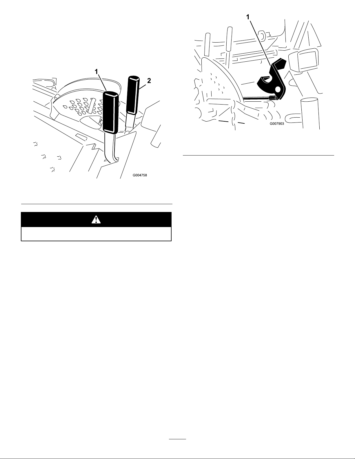
OperatingtheMower
RaisingandLoweringtheMowerwith
theDeckLiftLever
Thedeckliftleverraisesandlowersthemowerdeck
(Figure20).Theenginemustberunningforyouto
usethislever.
RaisingandLoweringtheMowerwith
theDeckLiftPedal
Thefootoperatedliftpedalraisesandlowersthe
mowerdeck(Figure21).Theenginemustberunning
foryoutousethispedal.
Figure21
1.Footoperateddeckliftpedal
Figure20
1.Deckliftlever
•Tolowerthemowerdeck,pushtheleverforward.
•Toraisethemoverdeck,pulltheleverrearward.
Important:Donotcontinuetoholdthelever
backorforwardafterthemowerhasfullyraised
orlowered.Doingsowilldamagethehydraulic
system.
Note:Tolockthemowerdeckinaraisedposition,
raisethedeckpastthe6inch(15cm)position,remove
theheightofcutstoppin(refertoAdjustingthe
Height-of-Cut),andplacethepininthe6inch(15cm)
height-of-cutposition(Figure23).
•Pressdownonthetopofliftpedaltoraisethe
mowerdeck.
•Pressdownonthebottomofliftpedaltolowerthe
mowerdeck.
Important:Donotcontinuetoholdthepedal
downafterthemowerdeckhasbeenfullyraised
orlowered.Doingsowilldamagethehydraulic
system.
Note:Tolockthemowerdeckinaraisedposition,
raisethedeckpastthe6inch(15cm)position,remove
theheightofcutstoppin(refertoAdjustingthe
Height-of-Cut),andplacethepininthe6inch(15cm)
height-of-cutposition(Figure23).
EngagingthePowerTakeOff(PTO)
Thepowertakeoff(PTO)switchstartsandstopsthe
mowerbladesandsomepoweredattachments.
1.Iftheengineiscold,allowtheenginetowarmup5
to10minutesbeforeengagingthePTO.
2.Whileseatedintheseat,releasethepressureonthe
tractioncontrolleversandplacetheminneutral.
3.PulluponthePTOswitchtoengageit(Figure22).
27
Page 28

Figure22
1.PTOswitch
DisengagingthePTO
Todisengage,pushthePTOswitchtotheoffposition.
AdjustingtheHeight-of-Cut
Theheight-of-cutisadjustedfrom1to6inches
(2.5to15.8cm)in1/4inch(6mm)incrementsby
relocatingthestoppinintodifferentholelocations.
1.Withtheenginerunning,pullbackonthedeck
liftleveruntilthemowerdeckisfullyraisedand
releasetheleverimmediately(Figure23).
2.Toadjust,rotatethestoppinuntiltherollpin
initlinesupwiththeslotsintheholesinthe
height-of-cutbracketandremoveit(Figure23).
Figure23
1.Deckliftlever3.Heightofcutstop
2.Stoppin
4.Adjusttheanti-scalprollersandskidsasrequired.
3.Selectaholeintheheight-of-cutbracket
correspondingtotheheight-of-cutdesired,insert
thepin,androtateitdowntolockitinplace
(Figure23).
Note:Therearefourrowsofholepositions
(Figure23).Thetoprowgivesyoutheheightofcut
listedabovethepin.Thesecondrowdowngives
youtheheightlistedplus1/4inch(6mm).The
thirdrowdowngivesyoutheheightlistedplus1/2
inch(12mm).Thebottomrowgivesyoutheheight
listedplus3/4inch(18mm).Forthe6inch(15.8
cm)positionthereisonlyonehole,locatedinthe
secondrow .Thisdoesnotadd1/4inch(6mm)to
the6inch(15.8cm)position.
AdjustingtheSkids
Mounttheskidsinthelowerpositionwhenoperating
inheightofcutshigherthan2-1/2inches(64mm)and
inthehigherpositionwhenoperatinginheightofcuts
lowerthan2-1/2inches(64mm).
Note:OnGuardian
worn,youcanswitchtheskidtotheoppositesidesof
themower,ippingthemover.Thiswillallowyouto
usetheskidslongerbeforereplacingthem.
1.DisengagethePTO,movethemotioncontrol
leverstotheneutrallockedposition,andsetthe
parkingbrake.
2.MovethethrottlelevertotheSlowposition,stop
theengine,removethekey ,andwaitforallmoving
partstostopbeforeleavingtheoperatingposition.
3.Loosenthescrewatthefrontofeachskid(2skids
onGuardiandecksand1skidonside-discharge
decks).
®
mowers,whentheskidsbecome
28
Page 29

Figure24
1.Screw3.Skid
2.Flange-headbolt4.Nut
4.Removetheange-headboltsandnutsfromeach
skid.
5.Moveeachskidtothedesiredpositionandsecure
themwiththeange-headboltsandnuts.
Note:Onlyusethetoporcentersetsofholesto
adjusttheskids.Thebottomholesareusedwhen
switchingsidesonaGuardianmowerdeck,atwhich
timetheybecomethetopholesontheotherside
ofthemower.
6.Torquethescrewatthefrontofeachskidto80to
100in-lb(9to11N⋅m).
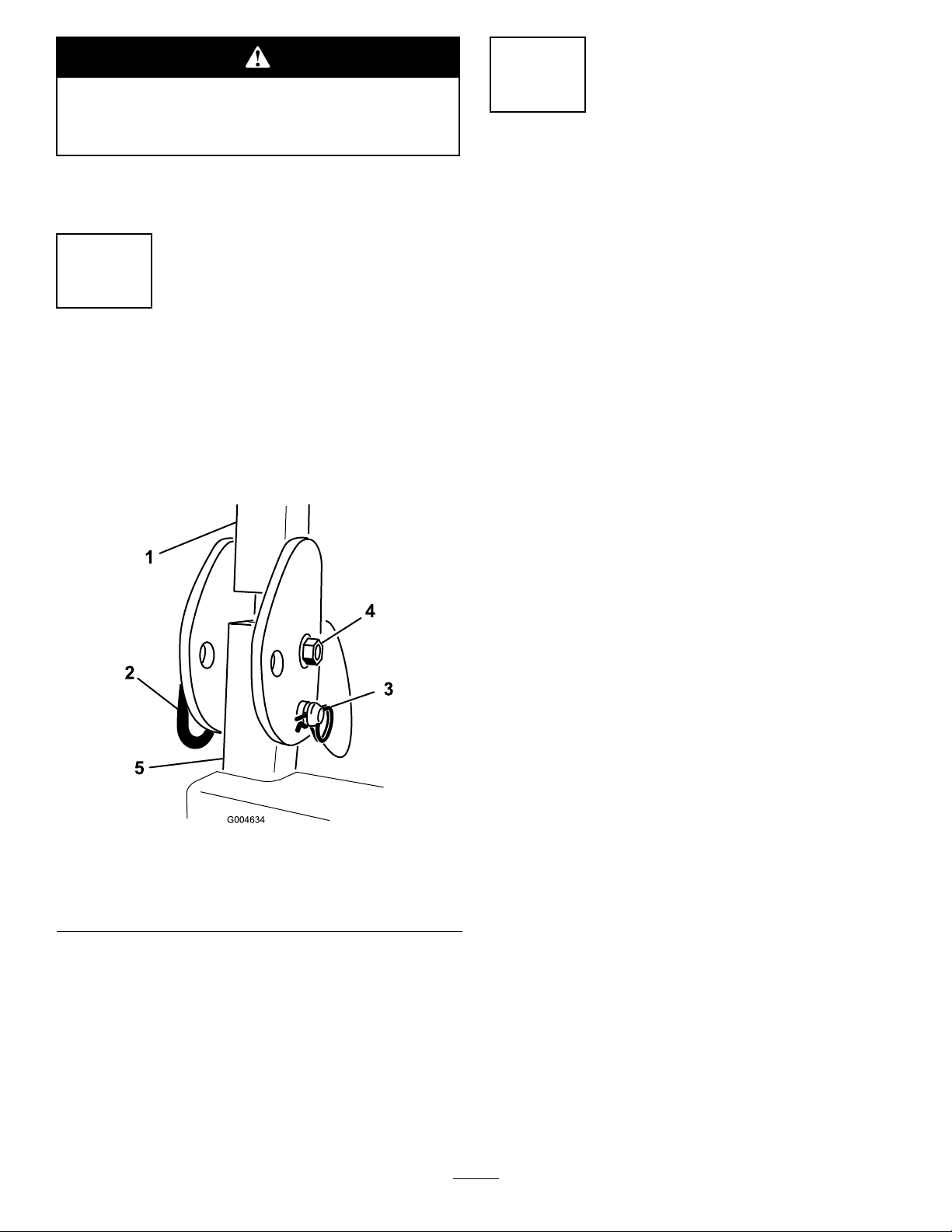
AdjustingtheRearAnti-Scalp
Rollers
Wheneveryouchangetheheight-of-cut,adjustthe
heightoftherearanti-scalprollers.
1.DisengagethePTO,movethemotioncontrol
leverstotheneutrallockedposition,andsetthe
parkingbrake.
Figure25
1.Flangenut
2.Bushing5.Bolt
3.Anti-scalproller
4.Spacer
4.Selectaholesotheanti-scalprollerispositioned
tothenearestcorrespondingheight-of-cutdesired
(Figure26).
Figure26
1.1-1/2inches(38mm)3.2-1/2inches(63mm)
2.2inches(51mm)4.3inches(76mm)and
higher
2.MovethethrottlelevertotheSlowposition,stop
theengine,removethekey ,andwaitforallmoving
partstostopbeforeleavingtheoperatingposition.
3.Afteradjustingtheheight-of-cut,adjusttherollers
byremovingtheangenut,bushing,spacer,and
bolt(Figure25).
5.Installtheangenutbushing,spacer,andbolt.
Torqueto40-45ft-lb(54-61N⋅m)(Figure25).
AdjustingtheRollers
Mounttherollersinthelowerpositionwhenoperating
inheightofcutshigherthan2-1/2inches(64mm)and
inthehigherpositionwhenoperatinginheightofcuts
lowerthan2-1/2inches(64mm).
1.DisengagethePTO,movethemotioncontrol
leverstotheneutrallockedpositionandsetthe
parkingbrake.
29
Page 30

2.MovethethrottlelevertotheSlowposition,stop
theengine,removethekey ,andwaitforallmoving
partstostopbeforeleavingtheoperatingposition.
3.Raisethefrontofthemachineandsupportiton
jackstands.
4.Removethefastenerssecuringeachrolleronyour
mowerdeckandmovetherollersupordownas
desired;refertoFigure27throughFigure31as
applicableforyourmower.
Figure29
GuardianMowerDecksOnly
1.Bolt3.Nut
2.Frontunder-deckroller4.Bracket
Figure27
AllMowerDecks
1.Frontroller
Figure28
GuardianMowerDecksOnly
1.Bolt4.Nut
2.Rearunder-deckroller5.Bracket
3.Spacer
2.Rollershaft
Figure30
Side-dischargeMowerDecksOnly
1.Bolt4.Nut
2.Chute-sideroller
3.Spacer
5.Bracket
30
Page 31

IfyourisefromtheseatwhenthePTOisengaged
thereisa1seconddelayandthentheenginestops.
TestingtheSafetyInterlockSystem
ServiceInterval:Beforeeachuseordaily
Testthesafetyinterlocksystembeforeyouusethe
machineeachtime.Ifthesafetysystemdoesnot
operateasdescribedbelow,haveanAuthorizedService
Dealerrepairthesafetysystemimmediately .
1.Sittingontheseat,engagetheparkingbrakeand
movethePTOtoon.Trystartingtheengine;the
engineshouldnotcrank.
Figure31
Side-dischargeMowerDecksOnly
1.Bolt
2.Rollershaft
3.Under-deckroller(2)
4.Bracket
5.Installthefastenersasillustrated.
TheSafetyInterlockSystem
Ifthesafetyinterlockswitchesaredisconnected
ordamagedthemachinecouldoperate
unexpectedlycausingpersonalinjury.
•Donottamperwiththeinterlockswitches.
•Checktheoperationoftheinterlock
switchesdailyandreplaceanydamaged
switchesbeforeoperatingthemachine.
UnderstandingtheSafetyInterlock
System
Thesafetyinterlocksystemisdesignedtopreventthe
enginefromstartingunless:
•Youaresittingontheseatortheparkingbrakeis
engaged.
•Thepowertakeoff(PTO)isdisengaged.
•Themotioncontrolleversareintheneutrallocked
position
•Theenginetemperatureisbelowthemaximum
operatingtemperature.
2.Sittingontheseat,engagetheparkingbrakeand
movethePTOtooff.Moveeithermotioncontrol
lever(outofneutrallockedposition).Trystarting
theengine;theengineshouldnotcrank.Repeatfor
othercontrollever.
3.Sittingontheseat,engagetheparkingbrake,move
thePTOswitchtooffandmovethemotioncontrol
leverstotheneutrallockedposition.Nowstartthe
engine.Whiletheengineisrunning,releasethe
parkingbrake,engagethePTOandriseslightly
fromtheseat;theengineshouldstopwithin2
seconds.
4.Withoutanoperatorontheseat,engagetheparking
brake,movethePTOswitchtooffandmovethe
motioncontrolleverstotheneutrallockedposition.
Nowstarttheengine.Whiletheengineisrunning,
centereithermotioncontrol;theengineshould
stopwithin2seconds.Repeatfortheothermotion
control.
5.Withoutanoperatorontheseat,disengagethe
parkingbrake,movethePTOswitchtooff,and
movethemotioncontrolleverstotheneutral
lockedposition.Trystartingtheengine;theengine
shouldnotcrank.
UsingtheSCMtoDiagnoseSystem
Problems
Themachineisequippedwithastandardcontrol
module(SCM)monitoringsystemthattracksthe
functionofvariouskeysystems.TheSCMislocated
undertherightcontrolpanel.Accessitthroughthe
sidepanelcover(Figure32).T oopenthesidepanel
cover,releasethe2latchesandpulloutonit.
Thesafetyinterlocksystemalsoisdesignedtostopthe
enginewhenthetractioncontrolsaremovedfromthe
neutrallockedpositionwiththeparkingbrakeengaged.
31
Page 32

Figure32
1.Sidepanelcover
2.Latches
OnthefaceoftheSCMare11LEDsthatilluminate
toindicatevarioussystemconditions.Sevenofthese
lightscanbeusedbytheoperatorforsystemdiagnosis.
RefertoFigure33foradescriptionofwhateach
lightmeans.FordetailsonusingtherestoftheSCM
functions,refertotheServiceManual,availablethrough
yourAuthorizedToroDistributor.
PositioningtheSeat
ChangingtheSeatPosition
Theseatcanmoveforwardandbackward.Positionthe
seatwhereyouhavethebestcontrolofthemachine
andaremostcomfortable.
1.Toadjust,movetheleversidewaystounlockthe
seat(Figure34).
Figure34
1.Backrestknob3.Lumbarsupport
adjustmentknob
2.Seatsuspensionknob4.Seatpositionadjustment
lever
Figure33
1.Hightemperatureshutdown—theenginetemperaturehas
exceededsafelevelsandtheenginehasbeenshutdown.
Checkthecoolingsystem.
2.Hightemperaturewarning—theenginetemperatureis
approachingunsafelevelsandthemowerdeckhasbeen
shutdown.Checkthecoolingsystem.
3.Operatorisintheseat
4.ThePTOisOn
5.Theparkingbrakeisnotengaged
6.ControlsareinNeutral
7.TheSCMisreceivingpowerandisoperational
2.Slidetheseattothedesiredpositionandrelease
levertolockinposition.
3.Verifythattheseathaslockedintoplaceby
attemptingtomoveitbackandforth.
ChangingtheSeatSuspension
Theseatcanbeadjustedtoprovideasmoothand
comfortableride.Positiontheseatwhereyouaremost
comfortable.
Withoutsittingontheseat,turntheknobinfronteither
directiontoprovidethebestcomfort(Figure34).
32
Page 33

Figure35
1.Seatsuspensionknob2.Operatorweightsetting
ChangingtheBackPosition
Thebackoftheseatcanbeadjustedtoprovidea
comfortableride.Positionthebackoftheseatwhereit
ismostcomfortable.
Toadjustit,turntheknob,undertheright-sidearm
rest,ineitherdirectiontoprovidethebestcomfort
(Figure34).
ChangingtheLumbarSupport
Thebackoftheseatcanbeadjustedtoprovidea
customizedlumbarsupportforyourlowerback.
Figure36
1.Seatlatch
PushingtheMachinebyHand
Ifthemachinebreaks,runsoutoffuel,etc.youmay
needtopushit.T odoso,yourstneedtoopenthe
hydraulicby-passvalves.
Toadjustit,turntheknob,undertheleft-sidearm
rest,ineitherdirectiontoprovidethebestcomfort
(Figure34).
UnlatchingtheSeat
Toaccessthehydraulicandothersystemsunderthe
seat,youneedtounlatchtheseatandswingitforward.
1.Usetheseatpositionadjustmentlevertoslidethe
seatallthewayforward.
2.Pushoneoftheseatlatches,locatedbehindandto
thesidesoftheseat,rearwardtounlatchtheseat
andpullforwardonthetopoftheseat(Figure36).
Important:Alwayspushthemachinebyhand.
Nevertowthemachinebecausehydraulicdamage
mayoccur.
PushingtheMachine
1.Disengagethepowertakeoff(PTO)andturn
theignitionkeytooff.Movetheleverstothe
neutrallockedpositionandapplytheparkingbrake.
Removethekey.
2.Lifttheseat.
3.Rotateeachby-passvalvecounterclockwise1turn
(Figure37).
Thisallowshydraulicuidtoby-passthepump
enablingthewheelstoturn.
Important:Donotrotatetheby-passvalves
morethan1turn.Thispreventsvalvesfrom
comingoutofthebodyandcausinguidto
runout.
33
Page 34

Figure37
1.Rightby-passvalve
2.Leftby-passvalve
4.Disengagetheparkingbrakebeforepushing.
ChangingtoMachineOperation
Rotateeachby-passvalveclockwise1turnandhand
tightenthem(torqueofapproximately71in-lb(8
N⋅m))(Figure37).
Note:Donotovertightentheby-passvalves.
Themachinewillnotdriveunlessby-passvalvesare
turnedin.
slope.Thiswillminimizetherampangle.Thetraileror
truckshouldbeaslevelaspossible.
Important:Donotattempttoturntheunitwhile
ontheramp;youmaylosecontrolanddriveoff
theside.
Avoidsuddenaccelerationwhendrivinguparampand
suddendecelerationwhenbackingdownaramp.Both
maneuverscancausetheunittotipbackward.
Loadingaunitontoatrailerortruckincreases
thepossibilityofbackwardtip-overandcould
causeseriousinjuryordeath.
•Useextremecautionwhenoperatingaunit
onaramp.
•Useonlyasingle,fullwidthramp;Donot
useindividualrampsforeachsideofthe
unit.
•Ifindividualrampsmustbeused,use
enoughrampstocreateanunbrokenramp
surfacewiderthantheunit.
•Donotexceeda15degreeanglebetween
rampandgroundorbetweenrampand
trailerortruck.
•Avoidsuddenaccelerationwhiledrivingunit
uparamptoavoidtippingbackward.
•Avoidsuddendecelerationwhilebacking
unitdownaramptoavoidtippingbackward.
LoadingMachines
Useextremecautionwhenloadingunitsontrailersor
trucks.Onefullwidthrampthatiswideenoughto
extendbeyondthereartiresisrecommendedinsteadof
individualrampsforeachsideoftheunit(Figure38).
Thelowerrearsectionofthetractorframeextends
backbetweentherearwheelsandservesasastopfor
tippingbackward.Havingafullwidthrampprovides
asurfacefortheframememberstocontactifthe
unitstartstotipbackward.Ifitisnotpossibletouse
onefullwidthramp,useenoughindividualrampsto
simulateafullwidthcontinuousramp.
Therampshouldbelongenoughsothattheangles
donotexceed15degrees(Figure38).Asteeperangle
maycausemowercomponentstogetcaughtastheunit
movesfromramptotrailerortruck.Steeperangles
mayalsocausetheunittotipbackward.Ifloadingon
ornearaslope,positionthetrailerortrucksoitison
thedownsideoftheslopeandtherampextendsupthe
34
Page 35

Figure38
1.Trailer3.Notgreaterthan
15degrees
2.Fullwidthramp4.Fullwidthramp—sideview
TransportingMachines
1.Fronttie-down(leftside
shown)
OperatingTips
Figure39
2.Reartie-downs
Drivingonthestreetorroadwaywithoutturn
signals,lights,reectivemarkings,oraslow
movingvehicleemblemisdangerousandcan
leadtoaccidentscausingpersonalinjury.
Donotdrivemachineonapublicstreetor
roadwaywithoutsigns,lights,and/ormarkings
requiredbylocalregulations.
Useaheavy-dutytrailerortrucktotransportthe
machine.Ensurethatthetrailerortruckhasall
necessarylightingandmarkingasrequiredbylaw .
Pleasecarefullyreadallthesafetyinstructions.
Knowingthisinformationcouldhelpyouorbystanders
avoidinjury.
Totransportthemachine:
•Ensurethatyourvehicle,hitch,safetychains,and
trailerareadequatefortheloadyouarepullingand
thattheymeetalllocaltrafcregulationsforyour
area.
•Lockthebrakeandblockthewheels.
•Securelyfastenthemachinetothetrailerortruck
withstraps,chains,cable,orropesasrequiredby
localtrafcregulationsinyourarea(Figure39).
FastThrottleSetting/GroundSpeed
Tomaintainenoughpowerforthemachineanddeck
whilemowing,operatetheengineatthefastthrottle
positionandadjustyourgroundspeedforconditions.
Agoodruletofollowis:decreasegroundspeedas
theloadonthecuttingbladesincreases;andincrease
groundspeedasloadonthebladesdecreases.
MowingDirection
Alternatemowingdirectiontoavoidmakingrutsinthe
turfovertime.Thisalsohelpsdisperseclippingswhich
enhancesdecompositionandfertilization.
CuttingSpeed
Toimprovecutquality,useaslowergroundspeedin
certainconditions.
AvoidCuttingTooLow
Ifthecuttingwidthofthemoweriswiderthanthe
moweryoupreviouslyused,raisethecuttingheightto
ensurethatuneventurfisnotcuttooshort.
35
Page 36

SelecttheProperHeight-of-CutSetting
toSuitConditions
Removeapproximately1inch(25mm)ornomorethan
1/3ofthegrassbladewhencutting.Inexceptionally
lushanddensegrass,youmayhavetoslowdownthe
forwardspeedand/orraisetheheight-of-cuttothe
nexthighersetting.
Important:Ifcuttingmorethat1/3ofthegrass
bladeoff,orinsparselonggrassordryconditions,
theuseofatsailbladesisrecommendedto
reduceair-bornechaff,debris,anddeckdrive
componentstrain.
LongGrass
Ifthegrassiseverallowedtogrowslightlylongerthan
normal,orifitcontainsahighdegreeofmoisture,raise
thecuttingheighthigherthanusualandcutthegrassat
thissetting.Thencutthegrassagainusingthelower,
normalsetting.
KeeptheMowerClean
Cleanclippingsanddirtfromtheundersideofthe
moweraftereachuse.Ifgrassanddirtbuildupinside
themower,cuttingqualitywilleventuallybecome
unsatisfactory.
Toreducetheriskofrehazard,keeptheengine,
mufer,batterycompartment,parkingbrake,cutting
units,andfuelstoragecompartmentfreeofgrass,
leaves,orexcessivegrease.Cleanupanyspilledoilor
fuel.
BladeMaintenance
Maintainasharpbladethroughoutthecuttingseason
becauseasharpbladecutscleanlywithouttearingor
shreddingthegrassblades.Tearingandshredding
turnsgrassbrownattheedges,whichslowsgrowth
andincreasesthechanceofdisease.Checktheblades
dailyforsharpness,andforanywearordamage.
Sharpenthebladesasnecessary.Ifabladeisdamaged
orworn,replaceitimmediatelywithagenuineToro
replacementblade.RefertoServicingtheCutting
Bladesin,pageformoreinformationoridentifying
bladeproblemsandsharpeningtheblades.
36
Page 37

Maintenance
Note:Determinetheleftandrightsidesofthemachinefromthenormaloperatingposition.
RecommendedMaintenanceSchedule(s)
MaintenanceService
Interval
Aftertherst10hours
Aftertherst50hours
Aftertherst200hours
Beforeeachuseordaily
Every50hours
Every150hours
Every200hours
MaintenanceProcedure
•Checkthealternatorbelttension.
•T orquetheframemountingbolts.
•T orquewheellugnuts.
•Changethemowerdeckgearboxlubricant
•Changetheengineoilandlter.
•Changethehydraulicoilandlter.
•T estthesafetysystem.
•Checktheengineoillevel.
•Checktheenginecoolantlevel.
•Cleantheradiatorwithcompressedair(donotusewater)
•Checkthehydraulicuidlevel.
•Checkthemowerblades.
•Cleanthemowerdeck.
•Greasethebearingandbushinggreasettings.
•Checkbatterycableconnections.
•Checkthetirepressure.
•Checktheconditionofthebladedrivebeltsonthemowerdeck.
•Checkthelubricantinthemowerdeckgearbox.
•Changetheengineoilandlter.
•Inspectcoolingsystemhosesandseals.Replacethemifcrackedortorn.
•Checkthealternatorbelttension.
•T orquewheellugnuts.
•Changethemowerdeckgearboxlubricant
Every400hours
Every800hours
Every1,500hours
Every2years
Important:Refertoyour
•Servicetheaircleaner.
•Replacethefuelltercanister.
•Checkthefuellinesandconnections.
•Changethehydraulicoilandlter.
•Inspectenginevalveclearance.RefertoyourEngineOperator’sManual.
•Replacemovinghoses
•Drainandcleanthefueltank.
•Flushandreplacecoolingsystemuid.
Engine Operator’ s Man ual
foradditionalmaintenanceprocedures.Adetailed
ServiceManualisalsoavailableforpurchasefromyourAuthorizedT oroDistributor.
37
Page 38

DailyMaintenanceChecklist
Duplicatethispageforroutineuse.
Fortheweekof: MaintenanceCheckItem
Mon.Tues.Wed.Thurs.Fri.
CheckSafetyInterlock
Operation
CheckGrassDeectorin
DownPosition(ifapplicable)
CheckParkingBrake
Operation
CheckFuelLevel
CheckHydraulicOilLevel
CheckEngineOilLevel
CheckCoolingSystemFluid
Level
CheckDrainWater/Fuel
Separator
CheckAirFilterRestriction
Indicator
CheckRadiator&Screenfor
Debris
CheckUnusualEngine
Noises
CheckUnusualOperating
Noises
CheckHydraulicHosesfor
Damage
CheckFluidLeaks
CheckTirePressure
CheckInstrumentOperation
CheckConditionofBlades
LubricateAllGreaseFittings
Touch-upDamagedPaint
1.Checkglowplugandinjectornozzles,ifhardstarting,excesssmokeorroughrunningisnoted.
3
1
2
Sat.Sun.
2.Immediatelyaftereverywashing,regardlessoftheintervallisted.
3.Ifindicatorshowsred
NotationforAreasofConcern
Inspectionperformedby:
ItemDate
Information
38
Page 39

Ifyouleavethekeyintheignitionswitch,someonecouldaccidentlystarttheengineandseriously
injureyouorotherbystanders.
Removethekeyfromtheignitionbeforeyoudoanymaintenance.
Figure40
ServiceIntervalChart
Lubrication
GreasingtheBearingsand
Bushings
ServiceInterval:Every50hours
Themachinehasgreasettingsthatmustbelubricated
regularlywithNo.2GeneralPurposeLithiumBase
Grease.Ifthemachineisoperatedundernormal
conditions,lubricateallbearingsandbushingsafter
every50hoursofoperation.Bearingsandbushings
mustbelubricateddailywhenoperatingconditionsare
extremelydustyanddirty.Dustyanddirtyoperating
conditionscouldcausedirttogetintothebearings
andbushings,resultinginacceleratedwear.Lubricate
thegreasettingsimmediatelyaftereverywashing,
regardlessofintervalspecied.
1.Wipethegreasettingscleansoforeignmatter
cannotbeforcedintothebearingorbushing.
2.Pumpgreaseintothettings.
Important:Thettingsontheaxlesofthecaster
wheelsarenotillustrated.Ensurethatyougrease
thesettingsaswell.
3.Wipeoffexcessgrease.
Figure41andFigure42illustratethelocationsofthe
greasettings.
39
Page 40

Figure41
40
Page 41

Figure42
Note:Bearinglifecanbenegativelyaffectedby
improperwashdownprocedures.Donotwashdownthe
unitwhenitisstillhotandavoiddirectinghigh-pressure
orhighvolumesprayatthebearingsorseals.
ServicingtheMowerDeck
GearBoxLubricant
ThegearboxisdesignedtooperatewithSAE80-90gear
lube.Althoughthegearboxisshippedwithlubricant
fromthefactory,checkthelevelbeforeoperatingthe
cuttingunitforthersttimeandevery150operating
hoursthereafter.Changethelubricantinthegearbox
every400operatinghours.
CheckingtheMowerDeckGearBox
Lubricant
ServiceInterval:Every150hours
1.Positionthemachineandcuttingunitonalevel
surface.
2.Lowerthemowerdecktothe1inch(2.5cm)
height-of-cut.
3.DisengagethePTO,movethemotioncontrollevers
totheneutrallockedpositionandsettheparking
brake.
4.MovethethrottlelevertotheSlowposition,stopthe
engine,removethekey ,andwaitforallmovingparts
tostopbeforeleavingtheoperatingposition.
41
Page 42

5.Liftthefootrest,exposingthetopofthemower
deck.
6.Removethedipstick/llplugfromthetopofthe
gearbox(Figure43)andmakesurethatthelubricant
isbetweenthemarksonthedipstick.
Figure43
1.Fillpluganddipstick
8.Replacethedrainplug.
9.Addenoughlubricant,approximately12oz.(283
ml),untilthelevelisbetweenthemarksonthe
dipstick.
Note:Donotoverllorthegearboxmaybe
damaged.
7.Ifthelubricantlevelislow,addenoughlubricant
untilthelevelisbetweenthemarksonthedipstick.
Note:Donotoverllorthegearboxmaybe
damaged.
ChangingtheMowerDeckGearBox
Lubricant
ServiceInterval:Aftertherst50hours
Every400hours
1.Positionthemachineandcuttingunitonalevel
surface.
2.Lowerthemowerdecktothe1inch(2.5cm)
height-of-cut.
3.DisengagethePTO,movethemotioncontrollevers
totheneutrallockedpositionandsettheparking
brake.
4.MovethethrottlelevertotheSlowposition,stopthe
engine,removethekey ,andwaitforallmovingparts
tostopbeforeleavingtheoperatingposition.
5.Liftthefootrest,exposingthetopofthemower
deck.
6.Removethedipstick/llplugfromthetopofthe
gearbox(Figure43).
7.Placeafunnelanddrainpanunderthedrainplug
locatedunderthefrontofthegearboxandremove
theplug,drainingthelubricantintothepan.
42
Page 43

EngineMaintenance
G004501
123456
7
AirCleanerMaintenance
Important:Avoidusinghighpressureairwhich
couldforcedirtthroughthelterintotheintake
tract.
4.Removeandreplacetheprimarylter(Figure44).
•Checktheaircleanerbodyfordamagewhichcould
possiblycauseanairleak.Replaceadamagedair
cleanerbody.Checkthewholecleanairintake
systemforleaks,damage,orloosehoseclamps.
•Servicetheaircleanerlterwhentheaircleaner
indicator(Figure44)showsredorevery400
hours(morefrequentlyinextremelydustyordirty
conditions).Donotoverservicetheairlter.
Figure44
1.Aircleanercover5.Aircleanerindicator
2.Gasket
3.Filter7.Rubberoutletvalve
4.Aircleanerbody
6.Aircleanerlatch
Important:Donotcleantheusedelementto
avoiddamagetotheltermedia.
5.Inspectthenewlterforshippingdamage,checking
thesealingendofthelterandthebody.
Important:Donotuseadamagedelement.
6.Ensurethatthefoamgasketisinplaceinthecover
andthatitisnottornordamaged(Figure44).If
itisdamaged,replaceit.
7.Insertthenewlterbyapplyingpressuretotheouter
rimoftheelementtoseatitinthecanister.
Important:Donotapplypressuretotheexible
centerofthelter.
8.Cleanthedirtejectionportlocatedintheremovable
cover,asfollows:
A.Removetherubberoutletvalvefromthecover
(Figure44).
B.Cleanthecavity.
C.Replacetheoutletvalve.
9.Installthecoverorientingtherubberoutletvalvein
adownwardposition—betweenapproximately5:00
to7:00whenviewedfromtheend.
10.Resettheindicator(Figure44)ifshowingred.
ServicingtheEngineOil
•Besurethecoverisseatedcorrectlyandsealswith
theaircleanerbody.
ServicingtheAirCleaner
ServiceInterval:Every400hours
1.Pullthelatchoutwardandrotatetheaircleaner
covercounter-clockwise(Figure44).
2.Removethecoverfromtheaircleanerbody
(Figure44).
3.Beforeremovingthelter,uselowpressure
air(40psi,cleananddry)tohelpremovelarge
accumulationsofdebrispackedbetweenoutsideof
primarylterandthecanister.
Thiscleaningprocesspreventsdebrisfrommigrating
intotheintakewhentheprimarylterisremoved.
CheckingtheEngineOilLevel
ServiceInterval:Beforeeachuseordaily
Theengineisshippedwithoilinthecrankcase;however,
theoillevelmustbecheckedbeforeandafterthe
engineisrststarted.Checkoillevelbeforeeachday’ s
operationoreachtimemachineisused.
Thecrankcasecapacityisapproximately4qt.(3.8l)
withthelter.Usehigh-qualityengineoilthatmeets
thefollowingspecications:
•APIClassicationLevelRequired:CH-4,CI-4or
higher.
•Preferredoil:SAE15W-40(above0°F(-17°C)
•Alternateoil:SAE10W -30or5W-30(all
temperatures)
Note:ToroPremiumEngineoilisavailablefromyour
distributorineither15W-40or10W-30viscosity .Seethe
partscatalogforpartnumbers.
43
Page 44

1.Parkthemachineonalevelsurface,lowerthe
mowerdeck,movethethrottlelevertotheSlow
position,stoptheengine,andremovethekeyfrom
theignitionswitch.Openthehood.
2.Removethedipstick(Figure45),wipeitclean,and
installthedipstick.Removethedipstickandcheck
theoillevel.
TheoillevelshouldbeuptotheFullmarkonthe
dipstick.
Figure46
1.Oillter
2.Drainplug
4.Cleantheareaaroundthedrainplug.
5.Removethedrainplugandallowtheoiltoowinto
drainpan.
6.Removeandreplacetheoillter(Figure46).
Figure45
1.Dipstick
2.Oilll
3.IftheoillevelisbelowtheFullmark,removethell
cap(Figure45)andaddoiluntilthelevelreachesthe
Fullmarkonthedipstick.
Important:Donotoverll.
Note:Useacleanfunneltopreventspills.
4.Installtheoilllcapandclosethehood.
ChangingtheEngineOilAndFilter
ServiceInterval:Aftertherst50hours
Every150hours
Changetheoilandlterinitiallyafterrst50hours
ofoperationandthenevery150hoursofoperation
thereafter.Ifpossible,runtheenginejustbefore
changingtheoilbecausewarmoilowsbetterand
carriesmorecontaminantsthancoldoil.
7.Aftertheoilisdrained,installthedrainplugand
wipeupanyoilthatisspilled.
8.Fillthecrankcasewithoil;refertoCheckingthe
EngineOilLevel.
1.Positionthemachineonalevelsurface.
2.Openthehood.
3.Setadrainpanundertheoilpanandinlinewith
thedrainplug(Figure46).
44
Page 45

FuelSystem
Maintenance
Note:RefertoAddingFuelforproperfuel
recommendations.
Undercertainconditions,dieselfuelandfuel
vaporsarehighlyammableandexplosive.A
reorexplosionfromfuelcanburnyouand
othersandcancausepropertydamage.
•Useafunnelandllthefueltankoutdoors,
inanopenarea,whentheengineisoffand
iscold.Wipeupanyfuelthatspills.
•Donotllthefueltankcompletelyfull.Add
fueltothefueltankuntilthelevelistothe
bottomofthellerneck.
•Neversmokewhenhandlingfuel,andstay
awayfromanopenameorwherefuel
fumesmaybeignitedbyaspark.
4.Removetheltercanisterandcleanthemounting
surface.
5.Lubricatethegasketontheltercanisterwithclean
oil.
6.Installtheltercanisterbyhanduntilthegasket
contactsmountingsurface,thenrotateitan
additional1/2turn.
7.Tightenthedrainplugonthebottomofthelter
canister.
CleaningtheFuelTank
ServiceInterval:Every2years
Drainandcleanfueltankevery2years.Also,remove
andcleanthein-linestrainersafterdrainingthetank.
Usecleandieselfueltoushoutthetank.
Important:Drainandcleanthetankifthefuel
systembecomescontaminatedorifthemachineis
tobestoredforanextendedperiod.
FuelLinesandConnections
•Storefuelinaclean,safety-approved
containerandkeepthecapinplace.
ServicingtheWaterSeparator
ServiceInterval:Every400hours
Drainwaterorothercontaminantsfromwaterseparator
(Figure47)daily.Replaceltercanisterafterevery400
hoursofoperation.
1.Placeacleancontainerunderthefuellter.
2.Loosenthedrainplugonthebottomofthelter
canister.
ServiceInterval:Every400hours
Checkthefuellinesandconnectionsevery400hours
oryearly,whichevercomesrst.Inspectthemfor
deterioration,damage,chafng,orlooseconnections.
BleedingtheFuelSystem
1.Parkthemachineonalevelsurface.Ensurethatthe
fueltankisatleasthalffull.
2.Unlatchandraisethehood.
3.Placearagundertheairbleedscrewonthefuel
injectionpumpandopenit(Figure48).
Figure47
1.Waterseparatorltercanister
3.Cleantheareawheretheltercanistermounts.
Figure48
1.Fuelinjectionpumpbleedscrew
4.TurnthekeyintheignitionswitchtotheOn
position.
45
Page 46

Theelectricfuelpumpwillbeginoperation,thereby
forcingairoutaroundtheairbleedscrew.
Theenginemaystartduringthisprocedure.
Movingfansandbeltsinarunningenginecan
severelyinjureyouorbystanders.
Keephands,ngers,looseclothing/jewelry,
andhairawayfromtheenginefanandbelt
duringthisprocedure.
5.LeavethekeyintheOnpositionuntilasolidstream
offuelowsoutaroundthescrew .
6.TightenthescrewandturnkeytotheOffposition.
Note:Normally,theengineshouldstartafterabove
bleedingproceduresarefollowed.However,if
enginedoesnotstart,airmaybetrappedbetween
injectionpumpandinjectors;refertoBleedingAir
FromtheInjectors.
Theenginemaystartduringthisprocedure.
Movingfansandbeltsinarunningenginecan
severelyinjureyouorbystanders.
Keephands,ngers,looseclothing/jewelry,
andhairawayfromtheenginefanandbelt
duringthisprocedure.
4.Tightenthepipeconnectorsecurelywhenitattains
asolidow .
5.TurnthekeytotheOffposition.
6.Repeatthisprocedurefortheremainingnozzles.
BleedingAirFromtheInjectors
Note:Thisprocedureshouldbeusedonlyifthefuel
systemhasbeenpurgedofairthroughnormalpriming
proceduresandenginewillnotstart;refertoBleeding
theFuelSystem.
1.Placearagunderthepipeconnectioncomingfrom
theinjectionpumptotheNo.1injectornozzleas
illustratedinFigure49.
Figure49
1.PipeconnectionfromtheinjectionpumptotheNo.1
injectornozzle
2.MovethethrottletotheFastposition.
3.TurntheignitionkeytheStartpositionandwatch
thefuelowaroundtheconnector.
46
Page 47

ElectricalSystem
Maintenance
Important:Wheneverworkingwiththeelectrical
system,alwaysdisconnectthebatterycables,
negative(-)cablerst,topreventpossiblewiring
damagefromshort-outs.
ServicingtheBattery
ServiceInterval:Every50hours
Warning
CALIFORNIA
Proposition65Warning
Batteryposts,terminals,andrelated
accessoriescontainleadandleadcompounds,
chemicalsknowntotheStateofCalifornia
tocausecancerandreproductiveharm.
Washhandsafterhandling .
Keepthetopofthebatteryclean.Ifyoustorethe
machineinalocationwheretemperaturesareextremely
high,thebatterywillrundownmorerapidlythanif
themachineisstoredinalocationwheretemperatures
arecool.
Batteryterminalsormetaltoolscouldshort
againstmetalmachinecomponentscausing
sparks.Sparkscancausethebatterygassesto
explode,resultinginpersonalinjury.
•Whenremovingorinstallingthebattery,do
notallowthebatteryterminalstotouchany
metalpartsofthemachine.
•Donotallowmetaltoolstoshortbetween
thebatteryterminalsandmetalpartsofthe
machine.
Incorrectbatterycableroutingcoulddamage
themachineandcablescausingsparks.Sparks
cancausethebatterygassestoexplode,
resultinginpersonalinjury.
•Alwaysdisconnectthenegative(black)
batterycablebeforedisconnectingthe
positive(red)cable.
•Alwaysconnectthepositive(red)battery
cablebeforeconnectingthenegative(black)
cable.
Keepthetopofthebatterycleanbywashingit
periodicallywithabrushdippedinammoniaor
bicarbonateofsodasolution.Flushthetopsurfacewith
wateraftercleaningit.Donotremovethellcapswhile
cleaningthebattery.
Thebatterycablesmustbetightontheterminalsto
providegoodelectricalcontact.
Ifcorrosionoccursattheterminals,disconnectthe
cables,negative(-)cablerst,andscrapetheclampsand
terminalsseparately.Reconnectthecables,positive(+)
cablerst,andcoattheterminalswithpetroleumjelly .
StoringtheBattery
Ifthemachinewillbestoredmorethan30days,remove
thebatteryandchargeitfully.Eitherstoreitonashelf
oronthemachine.Leavethecablesdisconnectedifit
isstoredonthemachine.Storethebatteryinacool
atmospheretoavoidquickdeteriorationofthechargein
thebattery.Topreventthebatteryfromfreezing,make
sureitisfullycharged.Thespecicgravityofafully
chargedbatteryis1.265-1.299.
CheckingtheFuses
Thefusesarelocatedunderthecontrolpanel.Access
themthroughthesidepanelcover(Figure50).Toopen
thesidepanelcover,releasethe2latchesandpullout
onit.
Ifthemachinestopsorhasotherelectricalsystemissues,
checkthefuses.Graspeachfuseinturnandremove
themoneatatime,checkingtoseeifanyareblown.If
youneedtoreplaceafuse,alwaysusethesametype
andamperageratedfuseastheoneyouarereplacing,
otherwiseyoucoulddamagetheelectricalsystem
47
Page 48

(refertothedecalnexttothefuses(Figure51)fora
diagramofeachfuseanditsamperage).
Note:Ifafuseblowsfrequently,youprobablyhavea
shortintheelectricalsystemandshouldhaveitserviced
byaqualiedservicetechnician.
DriveSystem
Maintenance
CheckingtheTirePressure
ServiceInterval:Every50hours
Checkthepressureafterevery50operatinghoursor
monthly,whicheveroccursrst(Figure52).
Maintaintheairpressureinthefrontandreartires.The
correctairpressureis15psi(103kPa)inthereartires
and25psi(172kPa)inthecasterwheels.Uneventire
pressurecancauseunevencut.Checkthetireswhen
theyarecoldtogetthemostaccuratepressurereading.
1.Sidepanelcover
Figure50
Figure51
2.Latches
Figure52
ReplacingtheCastorWheels
andBearings
1.Obtainanewcasterwheelassembly ,conebearings,
andbearingsealsforyourAuthorizedToro
Distributor.
2.Removethelocknutfromtheboltholdingthecastor
wheelassemblybetweenthecastorfork(Figure53).
48
Page 49

Figure53
1.Nut
2.Bearingspacer
3.Outerbearingseal
4.Conebearing9.Casterfork
5.Innerbearingseal
6.Spacer
7.Casterwheel
8.Axlebolt
3.Graspthecastorwheelandslidetheboltoutofthe
forkorpivotarm.
4.Discardtheoldcasterwheelandbearings.
5.Assemblethecastorwheelbypushingthecone
bearingsandseals,packedwithgrease,intothewheel
hub,positionedasshowninFigure53.
6.Slidethespacerintothewheelhubthroughthe
bearings,captivatingthespacerinsidethewheelhub
with2bearingspacers.
CoolingSystem
Maintenance
Dischargeofhotpressurizedcoolantor
touchinghotradiatorandsurroundingparts
cancausesevereburns.
•Donotremovetheradiatorcapwhenthe
engineishot.Alwaysallowtheengineto
coolatleast15minutesoruntiltheradiator
capiscoolenoughtotouchwithoutburning
yourhandbeforeremovingtheradiatorcap.
•Donottouchradiatorandsurroundingparts
thatarehot.
Therotatingfananddrivebeltcancause
personalinjury.
•Donotoperatethemachinewithoutthe
coversinplace.
•Keepngers,handsandclothingclearof
rotatingfananddrivebelt.
•Shutofftheengineandremovetheignition
keybeforeperformingmaintenance.
Important:Ensurethattheseallipsarenot
foldedin.
7.Installthecastorwheelassemblybetweenthecastor
forkandsecureitinplacewiththeboltandlocknut.
8.Tightenthenutuntilthewheelnolongerspinsfreely,
thenbackitoffjustuntilthewheelspinsfreely.
9.Attachagreaseguntothegreasettingonthecaster
wheelandllitwithNo.2GeneralPurposeLithium
BaseGrease.
Swallowingenginecoolantcancausepoisoning.
•Donotswallowenginecoolant.
•Keepoutofreachfromchildrenandpets.
CheckingtheCoolingSystem
ServiceInterval:Beforeeachuseordaily
Thecoolingsystemislledwitha50/50solutionof
waterandpermanentethyleneglycolantifreeze.Check
thelevelofthecoolantintheexpansiontankatthe
beginningofeachdaybeforestartingtheengine.The
capacityofthecoolingsystemis6quarts(7.5l).
49
Page 50

1.Checkthelevelofthecoolantintheexpansiontank
(Figure54).Thecoolantlevelshouldbebetweenthe
marksonthesideofthetank.
Figure54
1.Expansiontank
3.Aftertheradiatoristhoroughlycleaned,cleanout
debristhatmayhavecollectedinthechannelatthe
radiatorbase.
4.Closethehood.
2.Ifcoolantlevelislow ,removetheexpansiontank
capandreplenishthesystem.Donotoverll.
3.Installtheexpansiontankcap.
CleaningtheRadiator
ServiceInterval:Beforeeachuseordaily
Every1,500hours
Every200hours
Every2years
Topreventtheenginefromoverheating,theradiator
mustbekeptclean.Normally,checktheradiatordaily
and,ifnecessary,cleananydebrisofftheseparts.
However,itwillbenecessarytocheckandclean
theradiatorfrequentlyinextremelydustyanddirty
conditions.
Note:Ifthemowerdeckorengineshutsoffdue
tooverheating,rstchecktheradiatorforexcessive
buildupofdebris.
Cleantheradiatorasfollows:
1.Openthehood.
2.Workingfromthefansideoftheradiator,blowout
debriswithlowpressure(50psi)compressedair(do
notusewater).Repeatthestepfromthefrontof
theradiatorandagainfromthefanside.
50
Page 51

BrakeMaintenance
AdjustingtheParkingBrake
InterlockSwitch
1.Stopthemachine,movethecontrolleversfullyinto
theneutral-lockedposition,settheparkingbrake,
andremovetheignitionkey.
2.Removetheboltssecuringthefrontpaneland
removethepanel(Figure55).
4.Movetheswitchtowardthetabonthebrakeshaft
untilthedistancebetweenthetabandswitchbodyis
0.015to0.045inch(0.4to1mm)(Figure56).
5.Securetheswitch.
6.Testtheadjustmentasfollows:
A.Ensurethattheparkingbrakeisengagedandyou
arenotsittingontheseat,thenstarttheengine.
B.Movethecontrolleversoutoftheneutrallocked
position.
Theengineshouldstop.Ifnot,recheckthe
adjustmentyoumadetotheswitch.
7.Installthefrontpanel.
Figure55
1.Frontpanelbolts
3.Loosenthe2screwssecuringtheinterlockswitch.
Figure56
1.Tabonthebrakeshaft3.Screws
2.Parkingbrakeinterlock
switch
4.0.015to0.045inch(0.4to
1mm)
51
Page 52

BeltMaintenance
stoptheengine,settheparkingbrake,andremove
theignitionkey .
CheckingtheAlternatorBelt
ServiceInterval:Every200hours
Aftertherst10hours
Checktensionofalternatorbelt(Figure57)afterevery
200operatinghours.
1.Apply10lbofforcetothealternatorbelt,midway
betweenthepulleys.
2.Ifthedeectionisnot3/8in.(10mm),loosenthe
alternatormountingbolts.
2.Removethebeltcoversfromthetopofthecutting
unitandsetthecoversaside.
3.Usingabreakerbarorsimilartool,movetheidler
pulleyforthetopbelt(Figure58)awayfromthetop
drivebelttoreleasethebelttensionandallowthe
belttobeslippedoffthepulleys.
Figure58
1.Topbelt3.Bottombelt
2.Topidlerpulley4.Bottomidlerpulley
4.Usingabreakerbarorsimilartool,movetheidler
pulleyforthebottombelt(Figure58)awayfrom
thebottomdrivebelttoreleasethebelttensionand
allowthebelttobeslippedoffthepulleys.
Figure57
1.Mountingbolt2.Alternator
3.Increaseordecreasethealternatorbelttensionand
tightenthebolts.
4.Checkthedeectionofthebeltagaintoensurethat
thetensioniscorrect.
ReplacingtheBladeDrive
Belts
ServiceInterval:Every50hours
Thebladedrivebelts,tensionedbythespringloaded
idlerpulleys,areverydurable.However,aftermany
hoursofuse,thebeltswillshowsignsofwear.Signsof
awornbeltare:squealingwhenbeltisrotating,blades
slippingwhencuttinggrass,frayededges,burnmarks
andcracks.Replacethebeltsifanyoftheseconditions
areevident.
5.Routeanewbeltaroundthegearboxpulley,bottom
spindlepulleys,andidlerpulleyassemblyasshown
inFigure58.
6.Routeanewbeltaroundthetopspindlepulleysand
idlerpulleyassemblyasshowninFigure58.
7.Installthebeltcovers.
1.Lowerthecuttingunittothe1inchheightofcut
setting,movethethrottlelevertotheSlowposition,
52
Page 53

ControlsSystem
Maintenance
4.Holdingthecontrolleveragainsttheframe,move
theswitchtowardtheleveruntilthedistance
betweenleverandswitchbodyis0.015to0.045inch
(0.4to1mm)(Figure60).
AdjustingtheControlLever
NeutralInterlockSwitch
1.Stopthemachine,movethecontrolleversfullyinto
theneutral-lockedposition,settheparkingbrake,
andremovetheignitionkey.
2.Removetheboltssecuringthefrontpaneland
removethepanel(Figure59).
Figure59
1.Frontpanelbolts
5.Securetheswitch.
6.Repeatsteps3to5fortheotherlever.
7.Installthefrontpanel.
AdjustingtheControlLever
NeutralReturn
Ifthemotioncontrolleversdonotalignwiththeneutral
slotswhenreleasedfromthereversedriveposition,
adjustmentisrequired.Adjusteachlever,spring,and
rodseparately.
1.DisengagethePTO,movethemotioncontrollevers
totheneutrallockedpositionandsettheparking
brake.
2.MovethethrottlelevertotheSlowposition,stopthe
engine,removethekey ,andwaitforallmovingparts
tostopbeforeleavingtheoperatingposition.
3.Removetheboltssecuringthefrontpaneland
removethepanel(Figure61).
3.Loosenthe2screwssecuringtheinterlockswitch
(Figure60).
Figure60
1.Controllever3.Screws
2.Neutralinterlockswitch
4.0.015to0.045inch(0.4to
1mm)
Figure61
1.Frontpanelbolts
4.Moveoneoftheleverstotheneutralpositionbut
notlocked(Figure63).
5.Pulltheleverbackuntiltheclevispin(onanarm
abovethepivotshaft)contactstheendofthe
slot(justbeginningtoputpressureonthespring)
(Figure62).
53
Page 54

1.Clevispin
2.Slot
3.Jamnuts
Figure62
AdjustingtheTractionDrive
forNeutral
Thisadjustmentmustbemadewithdrivewheelsturning.
Mechanicalorhydraulicjacksmayfailto
supportmachineandcauseaseriousinjury .
•Usejackstandswhensupportingmachine.
•Donotusehydraulicjacks.
4.Adjustmentbolt
5.Yoke
6.Checkwherethecontrolleverisrelativetonotchin
console(Figure63).Itshouldbecenteredallowing
levertopivotoutwardtotheneutrallockposition.
Figure63
1.Neutralposition2.Neutrallockedposition
7.Ifadjustmentisneeded,loosenthenutandjamnut
againsttheyoke(Figure62).
8.Applyingslightrearwardpressureonthemotion
controllever,turntheheadoftheadjustmentbolt
intheappropriatedirectionuntilthecontrolleveris
centeredintheneutrallockposition(Figure62).
Theenginemustberunningtoperformthis
adjustment.Contactwithmovingpartsorhot
surfacesmaycausepersonalinjury.
Keephands,feet,face,clothing,andotherbody
partsawayfromrotatingparts,mufer,and
otherhotsurfaces.
1.Raisetheframeontostablejackstandssothatthe
drivewheelscanrotatefreely.
2.Slideseatforward,unlatchit,andswingitupand
forward.
3.Disconnecttheelectricalconnectorfromtheseat
safetyswitch.Temporarilyinstallajumperwire
acrossterminalsinthewiringharnessconnector.
4.Starttheengine,ensurethatthethrottleleveris
midwaybetweentheFastandSlowpositions,and
releasetheparkingbrake
Note:Themotioncontrolleversmustbein
theneutrallockedpositionwhilemakingany
adjustments.
5.Adjustthepumprodlengthononesidebyrotating
thehexshaft,intheappropriatedirection,untilthe
correspondingwheelisstillorslightlycreepingin
reverse(Figure64).
Note:Keepingrearwardpressureontheleverwill
keepthepinattheendoftheslotandallowthe
adjustmentbolttomovethelevertotheappropriate
position.
9.Tightenthenutandjamnut(Figure62).
10.Repeatsteps4through9fortheothercontrollever.
11.Installthefrontpanel.
54
Page 55

Figure64
1.Rightpumprod5.JamNut
2.Leftpumprod6.Hexshaft
3.Balljoint7.Balljoint
4.Bolt
Electricalsystemwillnotperformpropersafety
shutoffwithjumperwireinstalled.
•Removejumperwirefromwireharness
connectorandplugconnectorintoseat
switchwhenadjustmentiscompleted.
•Neveroperatethisunitwithjumperinstalled
andseatswitchbypassed.
12.Lowertheseatintoposition.
13.Removethejackstands.
AdjustingtheMaximum
GroundSpeed
1.DisengagethePTO,movethemotioncontrollevers
totheneutrallockedpositionandsettheparking
brake.
2.MovethethrottlelevertotheSlowposition,stopthe
engine,removethekey ,andwaitforallmovingparts
tostopbeforeleavingtheoperatingposition.
3.Removetheboltssecuringthefrontpaneland
removethepanel(Figure65).
6.Movethemotioncontrolleverforwardandreverse,
thenbacktoneutral.Thewheelmuststopturning
orslightlycreepinreverse.
7.MovethethrottlelevertotheFastposition.Make
surewheelremainsstoppedorslightlycreepsin
reverse,adjustifnecessary.
8.Repeatsteps5through7fortheotherside.
9.Tightenthejamnutsattheballjoints(Figure62).
10.MovethethrottlelevertotheSlowpositionandstop
theengine.
11.Removethejumperwirefromthewireharness
connectorandplugtheconnectorintotheseat
switch.
Figure65
1.Frontpanelbolts
4.Loosenthejamnutonthestopboltforoneofthe
controllevers(Figure66).
55
Page 56

Figure66
1.Stopbolt
2.Controllever4.0.060inch(1.5mm)
3.Jamnut
1.Controllever
2.Controlleverpost
Figure67
3.Bolts
5.Threadthestopboltallthewayin(awayfromthe
controllever).
6.Pushthecontrolleverallthewayforwarduntilit
stopsandholditthere.
7.Threadthestopboltout(towardsthecontrollever)
untilthereisagapof0.060inch(1.5mm)between
theheadofthestopboltandthecontrollever.
8.Tightenthejamnuttosecurethestopboltinplace.
9.Repeatsteps4through8fortheothercontrollever.
10.Installthefrontpanel.
Note:Ifyouwishtoreducethemaximummachine
speed,setthespeedforbothcontrolleversasdirected
above,thenbackeachstopboltoutanequalamount
towardthecontrolleveruntilyoureachthemaximum
speedyoudesire(youwilllikelyhavetotestyour
adjustmentseveraltimes).Ensurethatthemachine
drivesstraightanddoesnotturnwhenbothcontrol
leversarepushedallthewayforward.Ifthemachine
turns,youdonothavethestopboltsevenlysetandwill
needtoadjustthemfurther.
4.Havesomeonepushthecontrolleverposts(notthe
controllevers)allthewayforwardintothemaximum
speedpositionandholdthemthere.
5.Adjustthecontrolleverssothattheylineup
(Figure68)andtightenthebolts,securingthelevers
totheposts.
AdjustingtheTracking
1.DisengagethePTO,movethemotioncontrollevers
totheneutrallockedpositionandsettheparking
brake.
2.MovethethrottlelevertotheSlowposition,stopthe
engine,removethekey ,andwaitforallmovingparts
tostopbeforeleavingtheoperatingposition.
3.Loosentheboltssecuringthecontrollevers
(Figure67)
56
Page 57

HydraulicSystem
Maintenance
Thereservoirislledatthefactorywith
approximately5quarts(4.7l)ofhighqualitytractor
transmission/hydraulicuid.Therecommended
replacementuidisasfollows:
ToroPremiumTransmission/HydraulicTractorFluid
(Availablein5gallonpailsor55gallondrums.Seeparts
catalogorT orodistributorforpartnumbers.)
Alternateuids:IftheTorouidisnotavailable,
Mobil®424hydraulicuidmaybeused.
Note:T orowillnotassumeresponsibilityfordamage
causedbyimpropersubstitutions.
Note:Manyhydraulicuidsarealmostcolorless,
makingitdifculttospotleaks.Areddyeadditivefor
thehydraulicsystemoilisavailablein2/3oz.(20ml)
bottles.Onebottleissufcientfor4-6gal(15-221)of
hydraulicoil.Orderpartnumber44-2500fromyour
authorizedTorodistributor.
Figure68
CheckingtheHydraulic
System
ServiceInterval:Beforeeachuseordaily
Checkthelevelofthehydraulicuidbeforetheengine
isrststartedanddailythereafter.
1.Positionthemachineonalevelsurface.Placethe
controlsintheneutrallockedpositionandstartthe
engine.RunengineatlowestpossibleRPMtopurge
thesystemofair.DonotengagethePTO.Raise
thedecktoextendliftcylinders,stoptheengine,and
removethekey.
2.Raisetheseattoaccessthehydraulicuidtank.
3.Removethehydraulicllcap(Figure69)fromller
neck.
57
Page 58

Figure69
1.Dipstick2.Fillcap
Figure70
1.Hydraulicreservoirdrain
plug
2.Filter
3.Transmissioncasedrain
plug
4.Cleantheareaaroundthehydraulicoillterand
removeit(Figure70).
4.Removethedipstickandwipeitwithacleanrag
(Figure69).
5.Placethedipstickintothellerneck;thenremoveit
andchecklevelofuid(Figure69).
Iflevelisnotwithinnotchedareaofthedipstick,
addenoughhighqualityhydraulicuidtoraiselevel
towithinthenotchedarea.Donotoverll.
6.Replacethedipstickandthreadthellcap
nger-tightontollerneck.
7.Checkallhosesandttingsforleaks.
ChangingtheHydraulicOil
AndFilter
ServiceInterval:Aftertherst200hours
Every800hours
Initially,replacethehydraulicoillteraftertherst200
hoursofoperation.
Replacethelterandoilafterevery800hoursof
operation.
1.DisengagethePTO,movethemotioncontrollevers
totheneutrallockedpositionandsettheparking
brake.
2.MovethethrottlelevertotheSlowposition,stopthe
engine,removethekey ,andwaitforallmovingparts
tostopbeforeleavingtheoperatingposition.
3.Placealargepanunderthehydraulicreservoirand
transmissioncaseandremovetheplugs,drainingall
ofthehydraulicuid(Figure70).
5.Immediatelyinstallanewhydraulicoillter.
6.Installthehydraulicreservoirandtransmissioncase
drainplugs.
7.Fillthereservoirtotheproperlevel(approximately6
quarts);refertoCheckingtheHydraulicFluid.
8.Starttheengineandcheckforoilleaks.Allowthe
enginetorunforaboutveminutes,thenshutitoff.
9.Aftertwominutes,checkthelevelofthehydraulic
uid;refertoCheckingtheHydraulicFluid.
58
Page 59

MowerDeck
Maintenance
Checkthebladesdailyforsharpness,andforanywear
ordamage.Sharpenthebladesasnecessary.Ifabladeis
damagedorworn,replaceitimmediatelywithagenuine
Tororeplacementblade.
Ifyouraisethemachineusingonlyajackto
supportitwhileyouworkunderthemower
deck,thejackcouldtip,causingthemower
decktofall,crushingyouorbystanders.
Alwayssecurethemachinewithatleast2jack
standswhenyouhavethemowerdeckraised.
Onthetopofthemowerdeckaretwolinks
thatconnectthemtotheframe.Connectedto
theselinksaretorsionspringthatareunder
tension(Figure71).Ifyoudisconnectthelink
thestoredenergyinthetorsionspringwillbe
releasedandcouldcausethelinkstomove,
damagingyourhandsorngers.
Becarefulwhenremovingthemowerdeck
fromtheframeandsecurethelinksbefore
disconnectingthemfromtheframe.
Awornordamagedbladecanbreak,anda
pieceofthebladecouldbethrownintothe
operator’sorbystander’sarea,resultingin
seriouspersonalinjuryordeath.
•Inspectthebladeperiodicallyforwearor
damage.
•Replaceawornordamagedblade.
Inspectandcheckthebladesevery8hours.
BeforeInspectingorServicingthe
Blades
1.DisengagethePTO,movethemotioncontrollevers
totheneutrallockedpositionandsettheparking
brake.
2.MovethethrottlelevertotheSlowposition,stopthe
engine,removethekey ,andwaitforallmovingparts
tostopbeforeleavingtheoperatingposition.
Figure71
1.Link2.Torsionspring
ServicingtheCuttingBlades
Maintainsharpbladesthroughoutthecuttingseason
becausesharpbladescutcleanlywithouttearingor
shreddingthegrassblades.Tearingandshreddingturns
grassbrownattheedges,whichslowsgrowthand
increasesthechanceofdisease.
InspectingtheBlades
ServiceInterval:Beforeeachuseordaily
1.Inspectthecuttingedges(Figure72).Iftheedges
arenotsharporhavenicks,removeandsharpenthe
blades.RefertoSharpeningtheBlades.
2.Inspecttheblades,especiallythecurvedarea
(Figure72).Ifyounoticeanydamage,wear,oraslot
forminginthisarea(Figure72),immediatelyinstalla
newblade.
59
Page 60

CheckingforBentBlades
1.DisengagethePTO,movethemotioncontrollevers
totheneutrallockedpositionandsettheparking
brake.
2.MovethethrottlelevertotheSlowposition,stopthe
engine,removethekey ,andwaitforallmovingparts
tostopbeforeleavingtheoperatingposition.
3.Rotatethebladesuntiltheendsfaceforwardand
backward(Figure73).Measurefromalevelsurface
tothecuttingedge,positionA,oftheblades
(Figure73).Notethisdimension.
Figure72
1.CuttingEdge3.Wear/slotForming
2.CurvedArea4.Crack
Ifyouallowthebladetowear,aslotwillform
betweenthesailandatpartoftheblade.
Eventuallyapieceoftheblademaybreakoff
andbethrownfromunderthehousing,possibly
resultinginseriousinjurytoyouorbystanders.
•Inspectthebladeperiodicallyforwearor
damage.
•Nevertrytostraightenabladethatisbent
orweldabrokenorcrackedblade.
•Replaceawornordamagedblade.
Figure73
1.Measureherefromblade
tohardsurface
2.PositionA
4.Rotatetheoppositeendsofthebladesforward.
5.Measurefromalevelsurfacetothecuttingedgeof
thebladesatthesamepositionasinstep3above.
Thedifferencebetweenthedimensionsobtainedin
steps3and4mustnotexceed1/8inch(3mm).If
thisdimensionexceeds1/8inch(3mm),theblade
isbentandmustbereplaced;refertoRemovingthe
BladesandInstallingtheBlades.
Abladethatisbentordamagedcouldbreak
apartandcouldseriouslyinjureorkillyouor
bystanders.
•Alwaysreplacebentordamagedbladewith
anewblade.
•Neverleorcreatesharpnotchesinthe
edgesorsurfacesofblade.
60
Page 61

RemovingtheBlades
Bladesmustbereplacedifasolidobjectishit,ifthe
bladeisoutofbalanceorisbent.Toensureoptimum
performanceandcontinuedsafetyconformanceof
themachine,usegenuineT ororeplacementblades.
Replacementbladesmadebyothermanufacturersmay
resultinnon-conformancewithsafetystandards.
Contactwithasharpbladecancauseserious
injury.
Wearglovesorwrapsharpedgesoftheblade
witharag.
1.Holdthebladeendusingaragorthickly-padded
glove.
2.Removethebladebolt,anti-scalpplate,andblade
fromthespindleshaft(Figure76).
Figure75
1.Blade2.Balancer
InstallingtheBlades
1.Installthebladeontothespindleshaft(Figure76).
Important:Thecurvedpartoftheblademust
bepointingupwardtowardtheinsideofthe
mowertoensurepropercutting.
2.Installtheanti-scalpplateandbladebolt(Figure76).
SharpeningtheBlades
Whensharpeningblade,piecesofbladecould
bethrownandcauseseriousinjury.
Wearpropereyeprotectionwhensharpening
blades.
1.Sharpenthecuttingedgeatbothendsoftheblade
(Figure74).Maintaintheoriginalangle.Theblade
retainsitsbalanceifthesameamountofmaterialis
removedfrombothcuttingedges.
Figure74
1.Sharpenatoriginalangle
Figure76
1.Spindle
2.SailAreaofBlade
3.Anti-scalpplate
4.BladeBolt
3.Torquethebladeboltto85-110ft-lb(115-150N⋅m).
2.Checkthebalanceofthebladebyputtingitona
bladebalancer(Figure75).Ifthebladestaysina
horizontalposition,thebladeisbalancedandcanbe
used.Ifthebladeisnotbalanced,lesomemetaloff
theendofthesailareaonly(Figure76).Repeatthis
procedureuntilthebladeisbalanced.
CorrectingMowerDeck
Mismatch
Ifthecutisunevenacrossthemowerswath,correct
itasfollows:
1.Positionthemachineonalevelsurfaceontheshop
oor.
61
Page 62

2.Setthecuttingunittothedesiredheightofcut,
movethethrottlelevertotheSlowposition,stop
theengine,settheparkingbrake,andremovethe
ignitionkey .
3.Checkandadjustfrontandreartractortirepressure;
refertoCheckingTirePressurein,page.
4.Checkforbentblades.
5.Removethecoversfromthetopofthecuttingunits.
6.Rotatethebladeoneachspindleuntiltheendsface
forwardandbackward.
7.Measurefromtheoortothefronttipofthecutting
edge.
8.Adjustthejamnutssecuringthedeckyokes/chains
tothemowerdeckuntilthemowerdeckislevel.
4.Usingashortruler,measurefromtheoortothe
fronttipoftheblade.
5.Rotatethesamebladetiptotherearandmeasure
fromtheoortothetipofthebladeattherearof
thedeck.
6.Subtractthefrontdimensionfromtherear
dimensiontocalculatethebladepitch.
7.Adjustthejamnutssecuringthereardeck
yokes/chainstoraisetherearofthedecksothatthe
bladepitchissetto5/16inch(8mm)(Figure78).
Figure77
1.Chain
2.Yoke4.Mowerdeck
3.Jamnut
AdjustingtheMowerDeck
Pitch
Cuttingunitpitchisthedifferenceinheight-of-cutfrom
thefrontofthebladeplanetothebackoftheblade
plane.Tororecommendsabladepitchofapproximately
5/16inch(8mm).Thatisthebackofthebladeplaneis
5/16inch(8mm)higherthanthefront.
1.Positionthemachineonalevelsurfaceontheshop
oor.
2.Setthecuttingunittothedesiredheight-of-cut,
movethethrottlelevertotheSlowposition,stop
theengine,settheparkingbrake,andremovethe
ignitionkey .
3.Rotatethecenterbladesothatitpointsstraight
forward.
Figure78
1.Chain
2.Yoke4.Mowerdeck
3.Jamnut
ReplacingtheGrassDeector
Anuncovereddischargeopeningcouldallow
thelawnmowertothrowobjectsinthe
operator’sorbystander’sdirectionandresult
inseriousinjury.Also,contactwiththeblade
couldoccur.
•Neveroperatethelawnmowerwithouta
mulchkitorgrassdeectorinstalled.
•Makesurethegrassdeectorisinthedown
position.
1.Lowerthecuttingunittotheshopoor,movethe
throttlelevertotheSlowposition,stoptheengine,
settheparkingbrake,andremovetheignitionkey.
2.Removethelocknut,bolt,springandspacerholding
thedeectortothepivotbrackets(Figure79).
Removedamagedorworngrassdeector.
62
Page 63

Figure79
1.Bolt
2.Spacer6.GrassDeector
3.Locknut
4.Spring8.Righthandhookendof
5.Springinstalled
7.Lefthandhookendof
spring,placebehinddeck
edgebeforeinstallingbolt
spring
Cleaning
CleaningUndertheMower
ServiceInterval:Beforeeachuseordaily
Removethegrassbuildupunderthemowerdaily.
1.DisengagethePTO,movethemotioncontrollevers
totheneutrallockedpositionandsettheparking
brake.
2.MovethethrottlelevertotheSlowposition,stopthe
engine,removethekey ,andwaitforallmovingparts
tostopbeforeleavingtheoperatingposition.
3.Raisethemowertothetransportposition.
4.Raisethefrontofthemachinebyusingjackstands.
5.Thoroughlycleantheundersideofthemowerwith
water.
3.Placethespacerandspringbetweenthereplacement
grassdeectorbrackets(Figure79).Placetheleft
handJhookendofthespringbehindthedeckedge.
Note:MakesurethelefthandJhookendofthe
springisinstalledbehindthedeckedgebefore
installingtheboltasshowninFigure79.
4.Installtheboltandnut.PlacetherighthandJ
hookendofthespringaroundthegrassdeector
(Figure79).
Important:Thegrassdeectormustbeableto
lowerdownintoposition.Liftthedeectorup
totestthatitlowersintothefulldownposition.
WasteDisposal
Engineoil,batteries,hydraulicoil,andenginecoolant
arepollutantstotheenvironment.Disposeofthese
accordingtoyourstateandlocalregulations.
63
Page 64

Storage
A.Removethebatteryterminalsfromthebattery
posts.
Machine
1.Thoroughlycleanthemachine,deckandtheengine,
payingspecialattentiontotheseareas:
•Radiatorandradiatorscreen
•Underneaththedeck
•Underthedeckbeltcovers
•Counterbalancesprings
•PTOshaftassembly
•Allgreasettingsandpivotpoints
•Removethecontrolpanelandcleanoutinside
ofthecontrolbox
•Beneaththeseatplateandtopofthetransmission
2.Checkandadjustfrontandreartractortirepressure;
refertoCheckingTirePressurein,page.
3.Remove,sharpen,andbalancethemowerblades.
Installthebladesandtorquethebladefastenersto
85-110ft-lb(115-149N⋅m).
4.Checkallfastenersforloosenessandtightenthemas
necessary.Especiallytorquethe6boltssecuringthe
mowerdeckframetothetractionunit(Figure80)
to265ft-lb(359N⋅m).
B.Cleanthebattery,terminals,andpostswitha
wirebrushandbakingsodasolution.
C.Coatthecableterminalsandbatterypostswith
Grafo112Xskin-overgrease(T oroPartNo.
505-47)orpetroleumjellytopreventcorrosion.
D.Slowlyrechargethebatteryfor24hoursevery60
daystopreventleadsulfationofthebattery.
Engine
1.Draintheengineoilfromtheoilpanandreplace
thedrainplug.
2.Removeanddiscardtheoillter.Installanewlter.
3.Relltheenginewith4quarts(3.8l)ofrecommended
motoroil.RefertoChangingtheEngineOilin,
page.
4.Starttheengineandrunitatidlespeedfortwo
minutes.
5.Drainthefuelfromthefueltank,fuellines,pump,
lter,andseparator.Flushthefueltankwithclean
dieselfuelandconnectallfuellines.
6.Thoroughlycleanandservicetheaircleaner
assembly.
Figure80
Rightsidenotshown.
1.Bolts
5.Greaseoroilallgreasettings,pivotpoints,and
transmissionby-passvalvepins.Wipeoffanyexcess
lubricant.
6.Lightlysandandusetouchuppaintonpaintedareas
thatarescratched,chippedorrusted.Repairany
dentsinthemetalbody.
7.Servicethebatteryandcablesasfollows:
7.Sealtheaircleanerinletandtheexhaustoutletwith
weatherproofmaskingtape.
8.Checktheoilllercapandfueltankcaptoensure
theyaresecurelyinplace.
64
Page 65

Schematics
ElectricalSchematic(Rev.A)
65
Page 66

(Rev.A)
66
Page 67

Notes:
67
Page 68

Toro General Commercial Products Warranty
A Two-Year Limited Warranty
Conditions and Products Covered
The Toro Company and its affi liate, Toro Warranty Company,
pursuant to an agreement between them, jointly warrant your Toro
Commercial Product (“Product”) to be free from defects in materials or workmanship for two years or 1500 operational hours*,
whichever occurs fi rst. This warranty is applicable to all products
with the exception of Aerators (refer to separate warranty statements for these products). Where a warrantable condition exists,
we will repair the Product at no cost to you including diagnosis,
labor, parts, and transportation. This warranty begins on the date
the Product is delivered to the original retail purchaser.
* Product equipped with hour meter
Instructions for Obtaining Warranty Service
You are responsible for notifying the Commercial Products Distributor or Authorized Commercial Products Dealer from whom
you purchased the Product as soon as you believe a warrantable
condition exists. If you need help locating a Commercial Products
Distributor or Authorized Dealer, or if you have questions regarding your warranty rights or responsibilities, you may contact us at:
Toro Commercial Products Service Department
Toro Warranty Company
8111 Lyndale Avenue South
Bloomington, MN 55420-1196
952-888-8801
E-mail: commercial.warrnty@toro.com
Owner Responsibilities
As the Product owner, you are responsible for required maintenance and adjustments stated in your Operator’s Manual.
Failure to perform required maintenance and adjustments can be
grounds for disallowing a warranty claim.
Items and Conditions Not Covered
Not all product failures or malfunctions that occur during the
warranty period are defects in materials or workmanship. This
warranty does not cover the following:
Product failures which result from the use of non-Toro
•
replacement parts, or from installation and use of add-on,
or modifi ed non-Toro branded accessories and products. A
separate warranty may be provided by the manufacturer of
these items.
Product failures which result from failure to perform recom-
•
mended maintenance and/or adjustments. Failure to properly
maintain your Toro product per the Recommended Maintenance listed in the Operator’s Manual can result in claims for
warranty being denied.
Product failures which result from operating the Product in an
•
abusive, negligent or reckless manner.
Parts subject to consumption through use unless found to be
•
defective. Examples of parts which are consumed, or used
up, during normal Product operation include, but are not limited to, brakes pads and linings, clutch linings, blades, reels,
bed knives, tines, spark plugs, castor wheels, tires, fi lters,
belts, and certain sprayer components such as diaphragms,
nozzles, and check valves, etc.
Failures caused by outside infl uence. Items considered to be
•
outside infl uence include, but are not limited to, weather, stor-
age practices, contamination, use of unapproved coolants,
Countries Other than the United States or Canada
Customers who have purchased Toro products exported from the United States or Canada should contact their Toro Distributor (Dealer)
to obtain guarantee policies for your country, province, or state. If for any reason you are dissatisfi ed with your Distributor’s service or
have diffi culty obtaining guarantee information, contact the Toro importer.
lubricants, additives, fertilizers, water, or chemicals, etc.
Normal noise, vibration, wear and tear, and deterioration.
•
Normal “wear and tear” includes, but is not limited to, dam-
•
age to seats due to wear or abrasion, worn painted surfaces,
scratched decals or windows, etc.
Parts
Parts scheduled for replacement as required maintenance are warranted for the period of time up to the scheduled replacement time
for that part. Parts replaced under this warranty are covered for the
duration of the original product warranty and become the property
of Toro. Toro will make the fi nal decision whether to repair any ex-
isting part or assembly or replace it. Toro may use remanufactured
parts for warranty repairs.
Note Regarding Deep Cycle Battery Warranty:
Deep cycle batteries have a specifi ed total number of kilowatt-
hours they can deliver during their lifetime. Operating, recharging,
and maintenance techniques can extend or reduce total battery
life. As the batteries in this product are consumed, the amount
of useful work between charging intervals will slowly decrease
until the battery is completely worn out. Replacement of worn out
batteries, due to normal consumption, is the responsibility of the
product owner. Battery replacement may be required during the
normal product warranty period at owner’s expense.
Maintenance is at Owner’s Expense
Engine tune-up, lubrication cleaning and polishing, replacement of
fi lters, coolant, and completing Recommended Maintenance are
some of the normal services Toro products require that are at the
owner’s expense.
General Conditions
Repair by an Authorized Toro Distributor or Dealer is your sole
remedy under this warranty.
Neither The Toro Company nor Toro Warranty Company is
liable for indirect, incidental or consequential damages in
connection with the use of the Toro Products covered by this
warranty, including any cost or expense of providing substitute equipment or service during reasonable periods of
malfunction or non-use pending completion of repairs under
this warranty. Except for the Emissions warranty referenced
below, if applicable, there is no other express warranty. All
implied warranties of merchantability and fi tness for use are
limited to the duration of this express warranty.
Some states do not allow exclusions of incidental or consequential
damages, or limitations on how long an implied warranty lasts, so
the above exclusions and limitations may not apply to you. This
warranty gives you specifi c legal rights, and you may also have
other rights which vary from state to state.
Note regarding engine warranty:
The Emissions Control System on your Product may be covered
by a separate warranty meeting requirements established by the
U.S. Environmental Protection Agency (EPA) and/or the California
Air Resources Board (CARB). The hour limitations set forth above
do not apply to the Emissions Control System Warranty. Refer to
the Engine Emission Control Warranty Statement printed in your
Operator’s Manual or contained in the engine manufacturer’s
documentation for details.
Part No. 374-0031 Rev. D
 Loading...