

Toro Groundsmaster 360 Series, 30456, 330457, Groundsmaster 7200 Series, 30481 Operator's Manual
Page 1
FormNo.3424-939RevA
60in,62in,or72inRotaryMower
Groundsmaster
®
360Seriesand7200Series
TractionUnit
ModelNo.30353—SerialNo.403373001andUp
ModelNo.30456—SerialNo.403373001andUp
ModelNo.30457—SerialNo.403373001andUp
ModelNo.30481—SerialNo.403373001andUp
Registeratwww.T oro.com.
OriginalInstructions(EN)
*3424-939*A
Page 2
Model30456complieswithallrelevantEuropean
directiveswhentheCEKit(ModelNo.30658)is
installedonthecuttingunit.Modelnumber30353
requiresCEKitmodelnumber30685;30457requires
CEKit30683;30481requiresCEKit30679.For
additionaldetails,seetheseparateproductspecic
DeclarationofConformity(DOC)sheet.
g000502
Figure1
1.Safety-alertsymbol
WARNING
CALIFORNIA
Proposition65Warning
Useofthisproductmaycauseexposure
tochemicalsknowntotheStateof
Californiatocausecancer,birthdefects,
orotherreproductiveharm.
Introduction
Thisrotary-bladelawncuttingdeckismounted
toaride-onmachineandisintendedtobeused
byprofessional,hiredoperatorsincommercial
applications.Itisprimarilydesignedforcuttinggrass
onwell-maintainedlawnsinparks,sportselds,and
oncommercialgrounds.
Readthisinformationcarefullytolearnhowtooperate
andmaintainyourproductproperlyandtoavoid
injuryandproductdamage.Youareresponsiblefor
operatingtheproductproperlyandsafely
Visitwww.T oro.comforproductsafetyandoperation
trainingmaterials,accessoryinformation,helpnding
adealer,ortoregisteryourproduct.
Thismanualuses2wordstohighlightinformation.
Importantcallsattentiontospecialmechanical
informationandNoteemphasizesgeneralinformation
worthyofspecialattention.
Contents
Safety.......................................................................3
GeneralSafety...................................................3
SafeOperatingPractices....................................3
SafetyandInstructionalDecals..........................4
Setup........................................................................6
RemovingtheExistingCuttingUnit(If
Equipped).......................................................6
InstallingtheNewCuttingUnit............................7
LevelingtheCuttingUnit.....................................7
Operation..................................................................8
Adjustments........................................................8
OperatingTips.................................................12
Maintenance...........................................................13
RecommendedMaintenanceSchedule(s)...........14
DailyMaintenanceChecklist.............................14
Lubrication........................................................15
ReplacingtheBladeDriveBelts........................17
ServicingtheCuttingBlades.............................17
CleaningUndertheCuttingUnit........................20
Storage...................................................................21
Wheneveryouneedservice,genuineToroparts,or
additionalinformation,contactanAuthorizedService
DealerorToroCustomerServiceandhavethemodel
andserialnumbersofyourproductready.Themodel
andserialnumbersarestampedintoaplatethat
ismountedonthecuttingunithousing.Writethe
numbersinthespaceprovided.
ModelNo.
SerialNo.
Thismanualidentiespotentialhazardsandhas
safetymessagesidentiedbythesafety-alertsymbol
(Figure1),whichsignalsahazardthatmaycause
seriousinjuryordeathifyoudonotfollowthe
recommendedprecautions.
©2018—TheToro®Company
8111LyndaleAvenueSouth
Bloomington,MN55420
Contactusatwww.Toro.com.
2
PrintedintheUSA.
AllRightsReserved
Page 3

Safety
Thismachinehasbeendesignedinaccordancewith
ANSIB71.4-2017andENISO5395:2013.
GeneralSafety
Thisproductiscapableofamputatinghandsand
feetandofthrowingobjects.Alwaysfollowallsafety
instructionstoavoidseriouspersonalinjury.
Usingthisproductforpurposesotherthanitsintended
usecouldprovedangeroustoyouandbystanders.
•Readandunderstandthecontentsofthis
Operator’sManualbeforestartingtheengine.
•Donotputyourhandsorfeetnearmoving
componentsofthemachine.
•Donotoperatethemachinewithoutallguards
andothersafetyprotectivedevicesinplaceand
workingonthemachine.
•Keepclearofanydischargeopening.Keep
bystandersandpetsasafedistanceawayfrom
themachine.
•Keepchildrenoutoftheoperatingarea.Never
allowchildrentooperatethemachine.
•Parkthemachineonalevelsurface,lowerthe
cuttingunits,disengagethedrives,engagethe
parkingbrake(ifprovided),shutofftheengine,
andremovethekeybeforeleavingtheoperator's
positionforanyreason.
Improperlyusingormaintainingthismachinecan
resultininjury.Toreducethepotentialforinjury,
complywiththesesafetyinstructionsandalways
payattentiontothesafety-alertsymbol
meansCaution,Warning,orDanger—personalsafety
instruction.Failuretocomplywiththeseinstructions
mayresultinpersonalinjuryordeath.
,which
•Wearappropriateclothing,includingeye
protection;substantial,slip-resistantfootwear;
longpants,andhearingprotection.Tiebacklong
hairanddonotwearloosejewelry .
•Inspecttheareawheretheequipmentistobe
usedandremoveallobjects,suchasrocks,toys,
andwire,thatthemachinecanthrow.
•Checkthatoperator'spresencecontrols,safety
switches,andshieldsareattachedandfunctioning
properly.Donotoperatethemachineunlessthey
arefunctioningproperly.
•Stopthemachine,removethekey ,andwaitfor
allmovingpartstostopbeforeinspectingthe
attachmentafterstrikinganobjectorifthereis
anabnormalvibrationinthemachine.Makeall
necessaryrepairsbeforeresumingoperation.
•Keepyourhandsandfeetawayfromthecutting
units.
•Keepallpartsingoodworkingconditionandall
hardwaretightened.Replaceallwornordamaged
decals.
•Awornordamagedbladecanbreak,anda
pieceofthebladecouldbethrowntowardyouor
bystanders,resultinginseriouspersonalinjuryor
death.
•Inspectthebladeperiodicallyforwearordamage.
•Usecarewhencheckingtheblades.Wrapthe
bladesorweargloves,andusecautionwhen
servicingtheblades.Onlyreplaceorsharpenthe
blades;neverstraightenorweldthem.
•Onmulti-bladedmachines,takecareasrotating1
bladecancauseotherbladestorotate.
•Checktheblademountingboltsfrequentlytobe
surethattheyaretightenedtospecication.
Youcanndadditionalsafetyinformationwhere
neededthroughoutthisOperator’sManual.
SafeOperatingPractices
•Neverallowchildrenoruntrainedpeopleto
operateorservicethemachine.Localregulations
mayrestricttheageoftheoperator.Theowner
isresponsiblefortrainingalloperatorsand
mechanics.
•Becomefamiliarwiththesafeoperationofthe
equipment,operatorcontrols,andsafetysigns.
•Theowner/operatorcanpreventandisresponsible
foraccidentsthatmaycausepersonalinjuryor
propertydamage.
3
Page 4
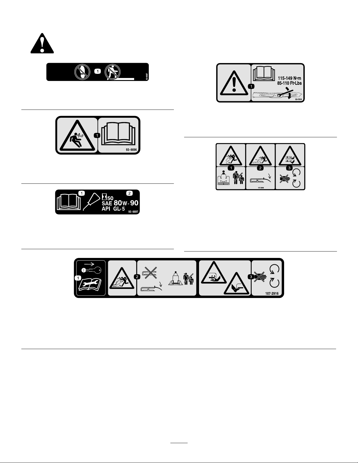
SafetyandInstructionalDecals
Safetydecalsandinstructionsareeasilyvisibletotheoperatorandarelocatednearanyarea
ofpotentialdanger.Replaceanydecalthatisdamagedormissing.
93-6687
decal93-6687
1.Donotstephere.
93–6696
1.Storedenergyhazard—readtheOperator'sManual.
93-6697
1.ReadtheOperator's
Manual.
2.AddSAE80w-90(API
GL-5)oilevery50hours.
decal93-7818
93-7818
1.Warning—readtheOperator'sManualforinstructionson
torquingthebladebolt/nutto115-149N-m(85-110ft-lb).
decal93-6696
decal107-2908
107-2908
1.Thrownobjecthazard—keepbystandersasafedistance
decal93-6697
fromthemachine.
2.Thrownobjecthazard—donotoperatethemowerwiththe
deectoruporremoved,keepthedeectorinplace.
3.Cutting/dismembermenthazardofhandorfoot,mower
blade—stayawayfrommovingparts.
1.Removethekeyandreadthe
Operator'sManualbeforeservicingor
performingmaintenance.
107-2916
2.Thrownobjecthazard—donotoperate
themowerwiththedeectorupor
removed;keepthedeectorinplace;
keepbystandersasafedistanceaway
fromthemachine.
4
decal107-2916
3.Cutting/dismembermenthazardof
handorfoot,mowerblade—stayaway
frommovingparts.
Page 5

112-1461
1.Beltrouting
117–4979
1.Entanglementhazard,belt—stayawayfrommovingparts,
keepallguardsandshieldsinplace.
decal133-8061
133-8061
decal112-1461
decal117-4979
120-6604
1.Thrownobjecthazard—keepbystandersawayfromthe
machine.
2.Cutting/dismembermenthazardofhand,mower
blade—stayawayfrommovingparts,keepallguardsand
shieldsinplace.
3.Cutting/dismembermenthazardoffoot,mowerblade—stay
awayfrommovingparts,keepallguardsandshieldsin
place.
decal120-6604
5
Page 6
Setup
B.Carefullyslidetheretainerpinfromthe
carrierframeandthepulllink(Figure2).
Note:Determinetheleftandrightsidesofthe
machinefromthenormaloperatingposition.
RemovingtheExisting
CuttingUnit(IfEquipped)
1.Parkthemachineonalevelsurfacewiththe
cuttingunitinthefullyraisedposition.Shut
offtheengine,engagetheparkingbrake,and
removethekey.
Note:Whenthecuttingunitisintheraised
position,thepull-linktorsionspringtension
(Figure2)isreduced,makingitmucheasierto
disconnectthepulllinksfromthemachine.
3.NotethelocationoftheHOCpinintheHOC
bracketforassemblypurposes(Figure3).
RemovetheHOCpinfromtheHOCbracket.
g017278
Figure3
1.HOCpin2.HOCbracket
Figure2
1.Pulllink(cuttingunit
raised)
2.Shoulderscrew6.Clevispin
3.Retainerpin7.Adjustmentclevis
4.Torsionspring
2.Disconnectthepulllinkfromeachsideofthe
machine(Figure2).
5.Cuttingunitliftchain
CAUTION
Thepulllinktorsionspringsmaycause
somerotationofthepulllinksduringthe
removalprocess.
Usecautionwhendisconnectingthepull
links.
4.Starttheengine,lowerthecuttingunittothe
ground,shutofftheengine,andremovethekey .
Note:Loweringthecuttingunitontofurniture
dolliesaidsinremovingthecuttingunit.
g017279
WARNING
IftheengineisstartedandthePTO
driveshaftisallowedtorotate,serious
personalinjuryandmachinedamage
couldresult.
•Whenthedriveshaftisdisconnected
fromthecuttingunit,donotstartthe
engineandengagethePTOswitch.
•Ifthedriveshaftisdisconnectedfrom
themower,removefuseF1(15A)from
thefuseblocktopreventunintentional
engagementofthePTOclutch.
5.DisconnecttheendyokeofthePTOdriveshaft
fromthecuttingunitgearboxshaft:
A.Removetherollpinfromtheendyokeand
thegearboxshaft(Figure4).
A.Removetheshoulderscrewthatsecures
theretainerpintothecarrierframe(Figure
2).
6
Page 7
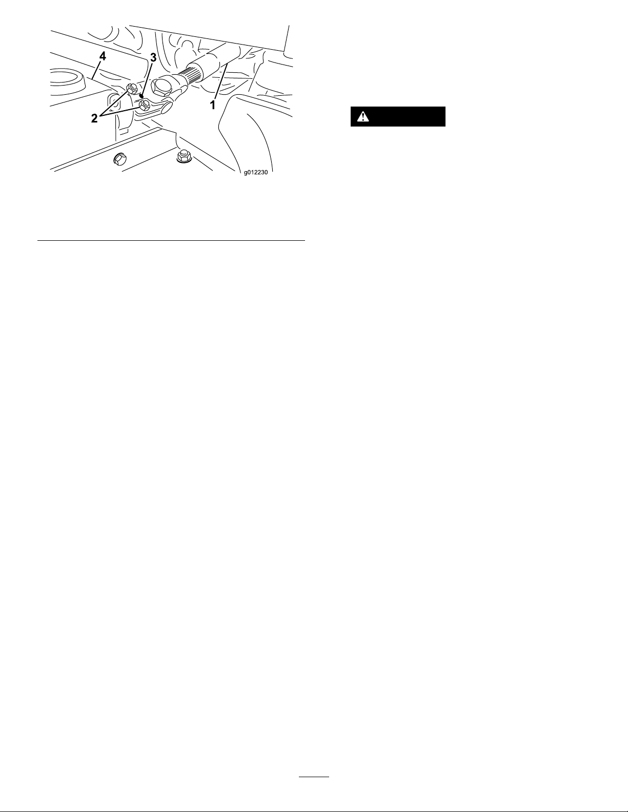
Figure4
1.Driveshaft
2.Capscrewsandlocknuts4.Gearbox
B.Loosenthe2capscrewsandlocknuts
(Figure4).
C.Slidethedriveshaftendyokefromthe
gearboxshaft.
3.Rollpin
Note:Raiseandtiethedriveshafttothe
frame.
6.Removethe4ringpinsandclevispinsthat
securetheliftchainstotheadjustmentclevises
onthemower(Figure2).
7.Slidethecuttingunitawayfromthemachine.
Note:Y oumayhavetoelevatethefrontofthe
tractionunittomovethecuttingunitawayfrom
themachine.
4.Starttheengineandfullyraisethecuttingunit.
Shutofftheengineandremovethekeyfromthe
ignitionswitch.
Note:Placeawoodblockorsimilarshimunder
eachlinktoholditintheraisedposition.
CAUTION
Thepulllinktorsionspringsmaycause
somerotationofthepulllinksduring
installation.
g012230
Usecautionwhenconnectingthepull
linkstothemachine.
5.Alignthepulllinktothecarrierframeandattach
thelinkwiththeretainerpin(Figure2).Secure
theretainerpintotheframewiththeshoulder
screw(Figure2).
6.InstalltheHOCpinintotheHOCbracketatthe
desiredheightofcut(Figure3).
7.LubricatethePTOdriveshaftgreasettings.
8.InstalltheF1fuse(15A)intothefuseblock.
LevelingtheCuttingUnit
LevelingSide-to-Side
1.Positionthemachineonalevelsurfaceonthe
shopoorandlowerthecuttingunit.
InstallingtheNewCutting
Unit
1.Slidethenewcuttingunitunderthecarrierframe
ofthemachine.
2.Installthe4clevispinsandringpinstosecure
thecuttingunitliftchainstotheadjustment
clevisesonthemower(Figure2).
3.ConnecttheendyokeofthePTOdriveshaftto
thecuttingunitgearbox;refertothefollowing
steps:
A.Alignthesplineandrollpinholesofthe
driveshaftyokewiththegearboxshaft.
B.SlidethePTOdriveshaftendyokeontothe
gearboxshaft.
C.SecuretheendyokeofthePTOdriveshaft
tothegearboxshaftwiththerollpin(Figure
4).
D.Tightenthelocknutstosecuretheendyoke
tothegearboxshaft(Figure4).T orquethe
locknutsto20to25N∙m(175to225in-lb).
2.MovethethrottlelevertotheSLOWposition,
shutofftheengine,engagetheparkingbrake,
andremovethekey.
3.Setthecuttingunittoa127mm(5inch)height
ofcut.
4.Checkandadjustthefrontandreartraction-unit
tirepressure;refertoOperator’sManualfor
pressurespecications.
5.Checkforbentblades;refertoCheckingfor
BentBlades(page18).
6.Rotatethebladeoneachspindleuntiltheends
faceforwardandbackward.
7.Measurefromtheoortothefronttipofthe
cuttingedge.
8.Adjustthejamnutssecuringthemower
yokes/chainstothemoweruntilthecuttingunit
islevel(Figure5).
7
Page 8
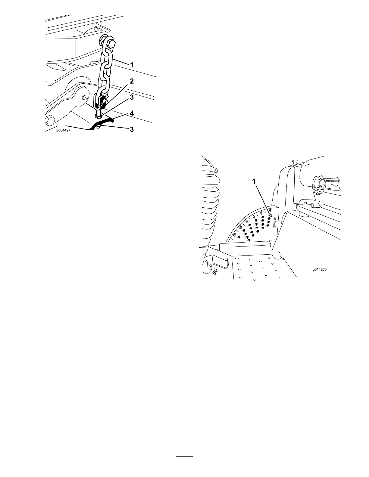
Figure5
1.Chain
2.Yoke4.Mower
3.Jamnut
LevelingFront-to-Back
Cuttingunitpitchisthedifferenceinheightofcutfrom
thefront-to-backofthebladeplane.Abladepitch
ofapproximately8to11mm(5/16to7/16inch)is
recommended(i.e.,thebackofthebladeplaneis8to
11mm(5/16to7/16inch)higherthanthefront).
Operation
Note:Determinetheleftandrightsidesofthe
machinefromthenormaloperatingposition.
Adjustments
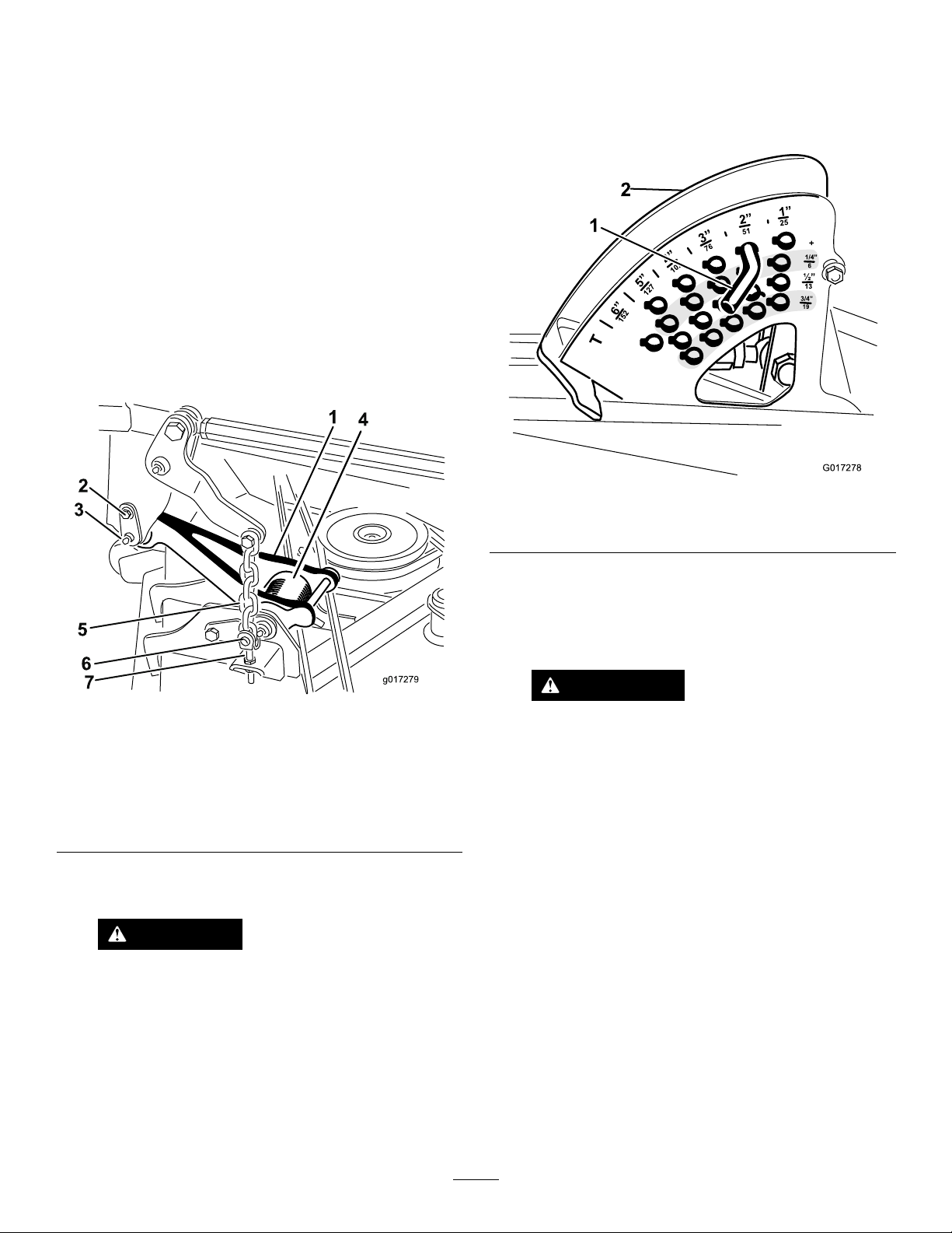
AdjustingtheHeight-of-Cut
Theheight-of-cutisadjustedfrom2.5to15.8cm(1to
6inches)in6mm(1/4inch)incrementsbyrelocating
thestoppinintodifferentholelocations.
1.Withtheenginerunning,pushbackonthe
g004497
cuttingunitliftswitchuntilthecuttingunitisfully
raisedandreleasetheswitchimmediately
(Figure6).
1.Setthecuttingunittothedesiredheight-of-cut,
movethethrottlelevertotheSLOWposition,
shutofftheengine,engagetheparkingbrake,
andremovethekey.
2.Rotatethecenterbladesothatitpointsstraight
forward.
3.Usingashortruler,measurefromtheoorto
thefronttipoftheblade.
4.Rotatethesamebladetiptotherearand
measurefromtheoortothetipofthebladeat
therearofthecuttingunit.
5.Subtractthefrontdimensionfromtherear
dimensiontocalculatethebladepitch.
6.Adjustthejamnutssecuringtherearmower
yokes/chains(Figure5)toraisetherearofthe
cuttingunitsothatthebladepitchissetto8to
11mm(5/16to7/16inch).
g014263
Figure6
1.Stoppin
2.Toadjusttheheightofcut,rotatethestoppin
untilthenubonitlinesupwiththeslotsinthe
holesintheheight-of-cutbracketandremoveit
(Figure6).
3.Selectaholeintheheight-of-cutbracket
correspondingtotheheight-of-cutdesired,insert
thepin,androtateitdowntolockitinplace
(Figure6).
Note:Thereare4rowsofholepositions
(Figure6).Thetoprowgivesyoutheheightof
cutlistedabovethepin.Thesecondrowdown
givesyoutheheightlistedplus6mm(1/4inch).
Thethirdrowdowngivesyoutheheightlisted
plus12mm(1/2inch).Thebottomrowgives
youtheheightlistedplus18mm(3/4inch).For
the15.8cm(6inch)positionthereisonly1hole,
8
Page 9

locatedinthesecondrow.Thisdoesnotadd6
mm(1/4inch)tothe15.8cm(6inch)position.
4.Adjusttheanti-scalprollersandskidsas
required.
AdjustingtheRearAnti-Scalp Rollers
Wheneveryouchangetheheight-of-cut,adjustthe
heightoftherearanti-scalprollers.
AdjustingtheSkid(s)
Mounttheskidsinthelowerpositionwhenoperating
inheightofcutshigherthan64mm(2-1/2inches)and
inthehigherpositionwhenoperatinginheightofcuts
lowerthan64mm(2-1/2inches).
Note:OnGuardian
worn,youcanswitchtheskidtotheoppositesidesof
thecuttingunit,ippingthemover.Thiswillallowyou
tousetheskidslongerbeforereplacingthem.
1.DisengagethePTOandengagetheparking
brake.
2.MovethethrottlelevertotheSLOWposition,
shutofftheengine,removethekey ,andwait
forallmovingpartstostopbeforeleavingthe
operatingposition.
3.Loosenthescrewatthefrontofeachskid.
Thereare2skidsonGuardianmowersand1
skidonside-dischargecuttingunits(Figure7).
®
mowers,whentheskidsbecome
1.DisengagethePTO,releasethetractionpedal,
andengagetheparkingbrake.
2.MovethethrottlelevertotheSLOWposition,
shutofftheengine,removethekey ,andwait
forallmovingpartstostopbeforeleavingthe
operatingposition.
3.Afteradjustingtheheight-of-cut,adjustthe
rollersbyremovingtheangenut,bushing,
spacer,andbolt(Figure8).
Figure7
1.Screw3.Skid
2.Flange-headbolt4.Nut
4.Removetheange-headboltsandnutsfrom
eachskid.
5.Moveeachskidtothedesiredpositionand
securethemwiththeange-headboltsandnuts.
Note:Onlyusethetoporcentersetsofholes
toadjusttheskids.Thebottomholesareused
whenswitchingsidesonaGuardianmower,at
whichtimetheybecomethetopholesonthe
othersideofthecuttingunit.
6.Torquethescrewatthefrontofeachskidto9to
11N-m(80to100in-lb).
g004483
Figure8
1.Flangenut
2.Bushing5.Bolt
3.Anti-scalproller
g004479
4.Selectaholesotheanti-scalprollerispositioned
4.Spacer
tothenearestcorrespondingheight-of-cut
desired(Figure9).
9
Page 10

Figure9
1.38mm(1-1/2inches)3.63mm(2-1/2inches)
2.51mm(2inches)4.76mm(3inches)and
higher
5.Installtheangenutbushing,spacer,andbolt.
Torqueto54to61N∙m(40to45ft-lb)(Figure8).
AdjustingtheRollers
Mounttherollersinthelowerpositionwhenoperating
inheightofcutshigherthan64mm(2-1/2inches)and
inthehigherpositionwhenoperatinginheightofcuts
lowerthan64mm(2-1/2inches).
1.DisengagethePTO,releasethetractionpedal,
andengagetheparkingbrake.
2.MovethethrottlelevertotheSLOWposition,
shutofftheengine,removethekey ,andwait
forallmovingpartstostopbeforeleavingthe
operatingposition.
3.Raisethefrontofthemachineandsupportiton
jackstands.
g004658
g004487
Figure10
AllCuttingUnits
1.Frontroller
2.Rollershaft
g004926
Figure11
Guardianmowersonly
1.Bolt4.Nut
2.Rearunder-cuttingunit
roller
3.Spacer
5.Bracket
4.Removethefastenerssecuringeachrolleron
yourcuttingunitandmovetherollersupordown
asdesired;refertoFigure10throughFigure14
asapplicableforyourcuttingunit.
Note:Youmayneedtoremovethefrontroller
forcertainGroundsmaster7200and7210
models.
Guardianmoweronly
1.Bolt3.Nut
2.Frontunder-cuttingunit
roller
10
g004923
Figure12
4.Bracket
Page 11

Figure13
Side-dischargecuttingunitsonly
1.Bolt4.Nut
2.Chute-sideroller
3.Spacer
Figure14
Side-dischargecuttingunitsonly
g004925
5.Bracket
g004924
1.Bolt
2.Rollershaft
5.Installthefastenersasillustrated.
3.Under-cuttingunitroller(2)
4.Bracket
11
Page 12

OperatingTips
insidethecuttingunit,cuttingqualitywilleventually
becomeunsatisfactory.
FastThrottleSetting/Ground
Speed
Tomaintainenoughpowerforthemachineanddeck
whilemowing,operatetheengineatthefastthrottle
positionandadjustyourgroundspeedforconditions.
Decreasethegroundspeedastheloadonthecutting
bladesincreases.Increasethegroundspeedasthe
loadonthebladesdecreases.
MowingDirection
Alternatemowingdirectiontoavoidmakingrutsin
theturfovertime.Thisalsohelpsdisperseclippings
whichenhancesdecompositionandfertilization.
CuttingSpeed
Toimprovecutquality ,useaslowergroundspeed.
AvoidCuttingTooLow
Ifthecuttingwidthofthecuttingunitiswiderthanthe
moweryoupreviouslyused,raisethecuttingheightto
ensurethatuneventurfisnotcuttooshort.
Toreducetheriskofrehazard,keeptheengine,
mufer,batterycompartment,parkingbrake,cutting
units,andfuelstoragecompartmentfreeofgrass,
leaves,orexcessivegrease.Cleanupanyspilledoil
orfuel.
BladeMaintenance
Maintainasharpbladethroughoutthecuttingseason
becauseasharpbladecutscleanlywithouttearingor
shreddingthegrassblades.Tearingandshredding
turnsgrassbrownattheedges,whichslowsgrowth
andincreasesthechanceofdisease.Checkthe
bladesdailyforsharpness,andforanywearor
damage.Sharpenthebladesasnecessary.Ifablade
isdamagedorworn,replaceitimmediatelywitha
genuineT ororeplacementblade.RefertoServicing
theCuttingBlades(page17).
SelecttheProperHeight-of-Cut
SettingtoSuitConditions
Removeapproximately1inch(25mm)orno
morethan1/3ofthegrassbladewhencutting.In
exceptionallylushanddensegrass,youmayhave
toslowdowntheforwardspeedand/orraisethe
height-of-cuttothenexthighersetting.
Important:Ifcuttingmorethan1/3ofthe
grassbladeoff,orinsparselonggrassor
dryconditions,theuseofatsailbladesis
recommendedtoreduceair-bornechaff,debris,
anddeckdrivecomponentstrain.
LongGrass
Ifthegrassiseverallowedtogrowslightlylongerthan
normal,orifitcontainsahighdegreeofmoisture,
raisethecuttingheighthigherthanusualandcutthe
grassatthissetting.Thencutthegrassagainusing
thelower,normalsetting.
KeeptheCuttingUnitClean
Cleanclippingsanddirtfromtheundersideofthe
cuttingunitaftereachuse.Ifgrassanddirtbuildup
12
Page 13

Maintenance
Note:Determinetheleftandrightsidesofthe
machinefromthenormaloperatingposition.
WARNING
Ifyouraisethemachineusingonlyajackto
supportitwhileyouworkunderthecutting
unit,thejackcouldtip,causingthemower
decktofall,crushingyouorbystanders.
Alwayssecurethemachinewithatleast2jack
standswhenyouhavethemowerdeckraised.
CAUTION
Onthetopofthecuttingunitare2linksthat
connectthemtotheframe.Connectedto
theselinksaretorsionspringthatareunder
tension(Figure15).Ifyoudisconnectthelink,
thestoredenergyinthetorsionspringwillbe
releasedandcouldcausethelinkstomove,
damagingyourhandsorngers.
Becarefulwhenremovingthecuttingunit
fromtheframeandsecurethelinksbefore
disconnectingthemfromtheframe.
Figure15
1.Link2.Torsionspring
g004920
13
Page 14

RecommendedMaintenanceSchedule(s)
MaintenanceService
Interval
Aftertherst50hours
Beforeeachuseordaily
Every50hours
MaintenanceProcedure
•Checktheconditionofthebladedrivebeltsonthecuttingunit.
•Checkthecuttingunitblades.
•Cleanthecuttingunit.
•Greasethebearingandbushinggreasettings.
DailyMaintenanceChecklist
Duplicatethispageforroutineuse.
Fortheweekof: MaintenanceCheckItem
Mon.Tues.Wed.Thurs.Fri.
CheckSafetyInterlock
Operation
CheckGrassDeectorin
DownPosition(ifapplicable)
CheckParkingBrake
Operation
CheckFuelLevel
CheckTirePressure
CheckInstrumentOperation
CheckConditionofBlades
LubricateAllGreaseFittings
Touch-upDamagedPaint
1.Immediatelyaftereverywashing,regardlessoftheintervallisted.
1
Sat.Sun.
NotationforAreasofConcern
Inspectionperformedby:
ItemDate
Information
CAUTION
Ifyouleavethekeyintheignitionswitch,someonecouldaccidentlystarttheengineand
seriouslyinjureyouorotherbystanders.
Removethekeyfromtheignitionbeforeyoudoanymaintenance.
14
Page 15

Lubrication
GreasingtheBearingsand Bushings
ServiceInterval:Every50hours
Dustyanddirtyoperatingconditionscouldcause
dirttogetintothebearingsandbushings,resulting
inacceleratedwear.Lubricatethegreasettings
immediatelyaftereverywashing,regardlessof
intervalspecied.
1.Wipethegreasettingscleansoforeignmatter
cannotbeforcedintothebearingorbushing.
Themachinehasgreasettingsthatmustbe
lubricatedregularlywithNo.2lithiumgrease.
Bearingsandbushingsmustbelubricateddailywhen
operatingconditionsareextremelydustyanddirty.
2.Pumpgreaseintothettings.
3.Wipeoffexcessgrease.
Figure16
g004645
15
Page 16

g004646
Figure17
Note:Bearinglifecanbenegativelyaffectedbyimproperwashdownprocedures.Donotwashtheunitwhenit
isstillhotandavoiddirectinghigh-pressureorhighvolumesprayatthebearingsorseals.
16
Page 17

ReplacingtheBladeDrive Belts
shreddingthegrassblades.Tearingandshredding
turnsgrassbrownattheedges,whichslowsgrowth
andincreasesthechanceofdisease.
ServiceInterval:Aftertherst50hours
Thebladedrivebelts,tensionedbythespringloaded
idlerpulleys,areverydurable.However,aftermany
hoursofuse,thebeltswillshowsignsofwear.Signs
ofawornbeltincludesquealingwhenthebeltis
rotating,bladesslippingwhencuttinggrass,poor
qualityofcut,frayededges,andburnmarksand
cracks.Replacethebeltsifanyoftheseconditions
areevident.
1.Lowerthecuttingunittothe1inchheightof
cutsetting,movethethrottlelevertotheSLOW
position,shutofftheengine,engagetheparking
brake,andremovethekey.
2.Removethebeltcoversfromthetopofthe
cuttingunitandsetthecoversaside.
3.Usingabreakerbarorsimilartool,movethe
idlerpulleyforthetopbelt(Figure18)awayfrom
thetopdrivebelttoreleasethebelttensionand
allowthebelttobeslippedoffthepulleys.
Checkthebladesdailyforsharpness,andforany
wearordamage.Sharpenthebladesasnecessary.
Ifabladeisdamagedorworn,replaceitimmediately
withagenuineTororeplacementblade.
DANGER
Awornordamagedbladecanbreak,anda
pieceofthebladecouldbethrowntowardyou
orbystanders,resultinginseriouspersonal
injuryordeath.
•Inspectthebladeperiodicallyforwearor
damage.
•Replaceawornordamagedblade.
Inspectandcheckthebladesevery8hours.
InspectingtheBlades
ServiceInterval:Beforeeachuseordaily
1.DisengagethePTO,releasethetractionpedal,
andengagetheparkingbrake.
Figure18
1.Topbelt3.Bottombelt
2.Topidlerpulley4.Bottomidlerpulley
4.Routeanewbeltaroundthegearboxpulley ,
bottomspindlepulleys,andidlerpulleyassembly
asshowninFigure18.
5.Routeanewbeltaroundthetopspindlepulleys
andidlerpulleyassemblyasshowninFigure18.
6.Greaseallmowerandcuttingunitdrivegrease
points.
7.Installthebeltcovers.
ServicingtheCutting Blades
Maintainsharpbladesthroughoutthecuttingseason
becausesharpbladescutcleanlywithouttearingor
2.MovethethrottlelevertotheSLOWposition,
shutofftheengine,removethekey ,andwait
forallmovingpartstostopbeforeleavingthe
operatingposition.
3.Inspectthecuttingedges(Figure19).Ifthe
edgesarenotsharporhavenicks,removeand
g004486
sharpentheblades.RefertoSharpeningthe
Blades(SharpeningtheBlades(page19)).
4.Inspecttheblades,especiallythesailarea
(Figure19).Ifyounoticeanydamage,wear,ora
slotforminginthisarea(Figure19),immediately
installanewblade.
DANGER
Ifyouallowthebladetowear,aslot
willformbetweenthesailandatpart
oftheblade.Eventuallyapieceofthe
blademaybreakoffandbethrownfrom
underthehousing,possiblyresultingin
seriousinjurytoyouorbystanders.
•Inspectthebladeperiodicallyforwear
ordamage.
•Nevertrytostraightenabladethat
isbentorweldabrokenorcracked
blade.
•Replaceawornordamagedblade.
17
Page 18

Figure20
g004633
Figure19
1.Cuttingedge3.Wear/slotforming
2.Sailarea4.Crack
CheckingforBentBlades
1.DisengagethePTO,releasethetractionpedal,
andengagetheparkingbrake.
1.Measureherefromblade
tohardsurface
4.Rotatetheoppositeendsofthebladesforward.
5.Measurefromalevelsurfacetothecuttingedge
ofthebladesatthesamepositionasinstep3
above.Thedifferencebetweenthedimensions
obtainedinsteps3and4mustnotexceed
3mm(1/8inch).Ifthisdimensionexceeds
3mm(1/8inch),thebladeisbentandmustbe
replaced;refertoRemovingtheBlades(page
18)andInstallingtheBlades(page19).
g004653
2.PositionA
WARNING
Abladethatisbentordamagedcould
breakapartandcouldseriouslyinjureor
killyouorbystanders.
•Alwaysreplacebentordamaged
bladewithanewblade.
•Neverleorcreatesharpnotchesin
theedgesorsurfacesofblade.
2.MovethethrottlelevertotheSLOWposition,
shutofftheengine,removethekey ,andwait
forallmovingpartstostopbeforeleavingthe
operatingposition.
3.Rotatethebladesuntiltheendsfaceforward
andbackward(Figure20).Measurefromalevel
surfacetothecuttingedge,positionA,ofthe
blades(Figure20).Notethisdimension.
RemovingtheBlades
Bladesmustbereplacedifasolidobjectishit,ifthe
bladeisoutofbalanceorisbent.T oensureoptimum
performanceandcontinuedsafetyconformanceof
themachine,usegenuineTororeplacementblades.
Replacementbladesmadebyothermanufacturers
mayresultinnon-conformancewithsafetystandards.
WARNING
Contactwithasharpbladecancauseserious
injury.
Wearglovesorwrapsharpedgesoftheblade
witharag.
18
Page 19

1.DisengagethePTO,releasethetractionpedal,
andengagetheparkingbrake.
2.MovethethrottlelevertotheSLOWposition,
shutofftheengine,removethekey ,andwait
forallmovingpartstostopbeforeleavingthe
operatingposition.
3.Holdthebladeendusingaragorthickly-padded
glove.
4.Removethebladebolt,anti-scalpplate,and
bladefromthespindleshaft;refertoFigure23
inInstallingtheBlades(page19).
SharpeningtheBlades
WARNING
Whensharpeningblade,piecesofbladecould
bethrownandcauseseriousinjury.
Wearpropereyeprotectionwhensharpening
blades.
InstallingtheBlades
1.Installthebladeontothespindleshaft(Figure
23).
Important:Thecurvedpartoftheblade
mustpointupwardtowardtheinsideofthe
cuttingunittoensurepropercutting.
2.Installtheanti-scalpplateandbladebolt(Figure
23).
1.Sharpenthecuttingedgeatbothendsofthe
blade(Figure21).Maintaintheoriginalangle.
Thebladeretainsitsbalanceifthesameamount
ofmaterialisremovedfrombothcuttingedges.
Figure21
1.Sharpenatoriginalangle
2.Checkthebalanceofthebladebyputtingiton
abladebalancer(Figure22).Ifthebladestays
inahorizontalposition,thebladeisbalanced
andcanbeused.Ifthebladeisnotbalanced,
lesomemetalofftheendofthesailareaonly
(Figure23).Repeatthisprocedureuntilthe
bladeisbalanced.
Figure22
1.Blade2.Balancer
g000276
Figure23
1.Spindle
2.Sailareaofblade
3.Anti-scalpplate
4.Bladebolt
g004480
3.Torquethebladeboltto115-150N⋅m
(85-110ft-lb).
CorrectingCuttingUnitMismatch
Ifthecutisunevenacrossthecuttingunitswath,
correctitasfollows:
1.Positionthemachineonalevelsurface.
2.Setthecuttingunittothedesiredheightofcut,
g000277
movethethrottlelevertotheSLOWposition,
shutofftheengine,engagetheparkingbrake,
andremovethekey.
3.Checkandadjustfrontandreartraction-unittire
pressure;refertothetractionunitOperator’s
Manual.
4.Checkforbentblades.
19
Page 20

5.Removethecoversfromthetopofthecutting
units.
6.Rotatethebladeoneachspindleuntiltheends
faceforwardandbackward.
7.Measurefromtheoortothefronttipofthe
cuttingedge.
8.Adjustthejamnutssecuringthecuttingunit
yokes/chainstothemoweruntilthecuttingunit
islevel(Figure24).
g004485
Figure25
g004497
Figure24
1.Front-moweryokechain4.Yoke
2.Rear-moweryokechain5.Jamnut
3.Chain
6.Mower
ReplacingtheGrassDeector
WARNING
Anuncovereddischargeopeningallows
themachinetothrowobjectstowardyouor
bystanders,whichcanresultinseriousinjury.
Contactwiththebladecanalsooccur.
•Neveroperatethemachinewithoutamulch
kitorgrassdeectorinstalled.
•Ensurethatthegrassdeectorislowered.
1.Lowerthecuttingunittotheground,movethe
throttlelevertotheSLOWposition,shutoffthe
engine,engagetheparkingbrake,andremove
thekey.
2.Removethelocknut,bolt,springandspacer
holdingthedeectortothepivotbrackets(Figure
25).Removedamagedorworngrassdeector.
1.Bolt
2.Spacer6.Grassdeector
3.Locknut
4.Spring8.Right-handhookendof
5.Springinstalled
7.Left-handhookendof
spring,placebehindthe
cuttingunitedgebefore
installingbolt
spring
3.Placethespacerandspringbetweenthe
replacementgrassdeectorbrackets(Figure
25).PlacethelefthandJhookendofthespring
behindthecuttingunitedge.
Note:Ensurethattheleft-handhookendofthe
springisinstalledbehindthecuttingunitedge
beforeinstallingtheboltasshowninFigure25.
4.Installtheboltandnut.Placetheright-hand
hookendofthespringaroundthegrass
deector(Figure25).
Important:Thegrassdeectormustbeable
tolowerdownintoposition.Liftthedeector
uptotestthatitlowersintothefulldown
position.
CleaningUndertheCutting Unit
ServiceInterval:Beforeeachuseordaily
Removethegrassbuildupunderthecuttingunitdaily .
1.DisengagethePTO,releasethetractionpedal
totheneutralposition,andengagetheparking
brake.
2.MovethethrottlelevertotheSLOWposition,
shutofftheengine,removethekey ,andwait
forallmovingpartstostopbeforeleavingthe
operator’sposition.
3.RaisethecuttingunittotheTRANSPORTposition.
20
Page 21

4.Useajacktoraisethefrontofthemachineand
supportitwithjackstands.
Storage
5.Thoroughlycleantheundersideofthecutting
unitwithwater.
1.DisengagethePTO,releasethetractionpedal
totheneutralposition,andengagetheparking
brake.
2.MovethethrottlelevertotheSLOWposition,
shutofftheengine,removethekey ,andwait
forallmovingpartstostopbeforeleavingthe
operator’sposition.
3.Allowtheenginetocoolbeforeadjusting,
cleaning,storing,orrepairingthemachine.
4.Thoroughlycleanthecuttingunit,payingspecial
attentiontotheseareas:
•Underneaththecuttingunit
•Underthecuttingunitbeltcovers
•PTOshaftassembly
•Allgreasettingsandpivotpoints
5.Checkandadjustthetraction-unitfrontandrear
tirepressure;refertothetraction-unitOperator’s
Manual.
6.Remove,sharpen,andbalancethecuttingunit
blades.Installthebladesandtorquetheblade
fastenersto85to1 10ft-lb(115to149N∙m).
7.Checkallfastenersforloosenessandtighten
themasnecessary.
8.Greaseoroilallgreasettingsandpivotpoints.
Wipeoffanyexcesslubricant.
9.Lightlysandandusetouchuppaintonpainted
areasthatarescratched,chippedorrusted.
Repairanydents.
21
Page 22

DeclarationofIncorporation
TheT oroCompany,8111LyndaleAve.South,Bloomington,MN,USAdeclaresthatthefollowingunit(s)
conform(s)tothedirectiveslisted,wheninstalledinaccordancewiththeaccompanyinginstructionsontocertain
ToromodelsasindicatedontherelevantDeclarationsofConformity.
ModelNo.
30353403373001andUp72inRotaryMower
30456403373001andUp
30457403373001andUp62inRotaryMower
30481403373001andUp
SerialNo.
ProductDescriptionInvoiceDescription
GM7200/GM36072in
BASEDECK
60inSideDischargeMowerGM720060inSDDECK
GM720062inBASEDECK
72inSideDischargeMower72inS.D.DECK(NON)C.E.
GeneralDescription
72inRotaryMower
60inRotaryMower
62inRotaryMower
72inRotaryMower
Directive
2006/42/EC,
2000/14/EC
2006/42/EC,
2000/14/EC
2006/42/EC,
2000/14/EC
2006/42/EC,
2000/14/EC
RelevanttechnicaldocumentationhasbeencompiledasrequiredperPartBofAnnexVIIof2006/42/EC.
Wewillundertaketotransmit,inresponsetorequestsbynationalauthorities,relevantinformationonthispartly
completedmachinery.Themethodoftransmissionshallbeelectronictransmittal.
ThismachineryshallnotbeputintoserviceuntilincorporatedintoapprovedToromodelsasindicatedonthe
associatedDeclarationofConformityandinaccordancewithallinstructions,wherebyitcanbedeclaredin
conformitywithallrelevantDirectives.
Certied:
AuthorizedRepresentative:
MarcelDutrieux
ManagerEuropeanProductIntegrity
ToroEuropeNV
Nijverheidsstraat5
2260Oevel
Belgium
JohnHeckel
Sr.EngineeringManager
811 1LyndaleAve.South
Bloomington,MN55420,USA
August22,2018
Tel.+3216386659
Page 23

CaliforniaProposition65WarningInformation
Whatisthiswarning?
Youmayseeaproductforsalethathasawarninglabellikethefollowing:
WARNING:CancerandReproductiveHarm—www.p65Warnings.ca.gov.
WhatisProp65?
Prop65appliestoanycompanyoperatinginCalifornia,sellingproductsinCalifornia,ormanufacturingproductsthatmaybesoldinorbroughtinto
California.ItmandatesthattheGovernorofCaliforniamaintainandpublishalistofchemicalsknowntocausecancer,birthdefects,and/orother
reproductiveharm.Thelist,whichisupdatedannually,includeshundredsofchemicalsfoundinmanyeverydayitems.ThepurposeofProp65isto
informthepublicaboutexposuretothesechemicals.
Prop65doesnotbanthesaleofproductscontainingthesechemicalsbutinsteadrequireswarningsonanyproduct,productpackaging,orliteraturewith
theproduct.Moreover,aProp65warningdoesnotmeanthataproductisinviolationofanyproductsafetystandardsorrequirements.Infact,the
CaliforniagovernmenthasclariedthataProp65warning“isnotthesameasaregulatorydecisionthataproductis‘safe’or‘unsafe.’”Manyofthese
chemicalshavebeenusedineverydayproductsforyearswithoutdocumentedharm.Formoreinformation,gotohttps://oag.ca.gov/prop65/faqs-view-all
AProp65warningmeansthatacompanyhaseither(1)evaluatedtheexposureandhasconcludedthatitexceedsthe“nosignicantrisklevel”;or(2)
haschosentoprovideawarningbasedonitsunderstandingaboutthepresenceofalistedchemicalwithoutattemptingtoevaluatetheexposure.
Doesthislawapplyeverywhere?
Prop65warningsarerequiredunderCalifornialawonly.ThesewarningsareseenthroughoutCaliforniainawiderangeofsettings,includingbutnot
limitedtorestaurants,grocerystores,hotels,schools,andhospitals,andonawidevarietyofproducts.Additionally ,someonlineandmailorder
retailersprovideProp65warningsontheirwebsitesorincatalogs.
.
HowdotheCaliforniawarningscomparetofederallimits?
Prop65standardsareoftenmorestringentthanfederalandinternationalstandards.TherearevarioussubstancesthatrequireaProp65warning
atlevelsthatarefarlowerthanfederalactionlimits.Forexample,theProp65standardforwarningsforleadis0.5μg/day,whichiswellbelow
thefederalandinternationalstandards.
Whydon’tallsimilarproductscarrythewarning?
•ProductssoldinCaliforniarequireProp65labellingwhilesimilarproductssoldelsewheredonot.
•AcompanyinvolvedinaProp65lawsuitreachingasettlementmayberequiredtouseProp65warningsforitsproducts,butothercompanies
makingsimilarproductsmayhavenosuchrequirement.
•TheenforcementofProp65isinconsistent.
•CompaniesmayelectnottoprovidewarningsbecausetheyconcludethattheyarenotrequiredtodosounderProp65;alackofwarningsfora
productdoesnotmeanthattheproductisfreeoflistedchemicalsatsimilarlevels.
WhydoesToroincludethiswarning?
Torohaschosentoprovideconsumerswithasmuchinformationaspossiblesothattheycanmakeinformeddecisionsabouttheproductstheybuyand
use.T oroprovideswarningsincertaincasesbasedonitsknowledgeofthepresenceofoneormorelistedchemicalswithoutevaluatingthelevelof
exposure,asnotallthelistedchemicalsprovideexposurelimitrequirements.WhiletheexposurefromT oroproductsmaybenegligibleorwellwithinthe
“nosignicantrisk”range,outofanabundanceofcaution,T orohaselectedtoprovidetheProp65warnings.Moreover,ifT orodoesnotprovidethese
warnings,itcouldbesuedbytheStateofCaliforniaorbyprivatepartiesseekingtoenforceProp65andsubjecttosubstantialpenalties.
RevA
Page 24

TheToroWarranty
ATwo-YearLimitedWarranty
ConditionsandProductsCovered
TheToroCompanyanditsafliate,ToroWarrantyCompany,pursuant
toanagreementbetweenthem,jointlywarrantyourT oroCommercial
product(“Product”)tobefreefromdefectsinmaterialsorworkmanship
fortwoyearsor1500operationalhours*,whicheveroccursrst.This
warrantyisapplicabletoallproductswiththeexceptionofAerators
(refertoseparatewarrantystatementsfortheseproducts).Wherea
warrantableconditionexists,wewillrepairtheProductatnocosttoyou
includingdiagnostics,labor,parts,andtransportation.Thiswarranty
beginsonthedatetheProductisdeliveredtotheoriginalretailpurchaser .
*Productequippedwithanhourmeter.
InstructionsforObtainingWarrantyService
YouareresponsiblefornotifyingtheCommercialProductsDistributoror
AuthorizedCommercialProductsDealerfromwhomyoupurchasedthe
Productassoonasyoubelieveawarrantableconditionexists.Ifyouneed
helplocatingaCommercialProductsDistributororAuthorizedDealer,or
ifyouhavequestionsregardingyourwarrantyrightsorresponsibilities,
youmaycontactusat:
ToroCommercialProductsServiceDepartment
ToroWarrantyCompany
811 1LyndaleAvenueSouth
Bloomington,MN55420-1196
952–888–8801or800–952–2740
E-mail:commercial.warranty@toro.com
OwnerResponsibilities
AstheProductowner,youareresponsibleforrequiredmaintenanceand
adjustmentsstatedinyourOperator'sManual.Failuretoperformrequired
maintenanceandadjustmentscanbegroundsfordisallowingawarranty
claim.
ItemsandConditionsNotCovered
Notallproductfailuresormalfunctionsthatoccurduringthewarranty
periodaredefectsinmaterialsorworkmanship.Thiswarrantydoesnot
coverthefollowing:
•Productfailureswhichresultfromtheuseofnon-Tororeplacement
parts,orfrominstallationanduseofadd-on,ormodiednon-Toro
brandedaccessoriesandproducts.Aseparatewarrantymaybe
providedbythemanufactureroftheseitems.
•Productfailureswhichresultfromfailuretoperformrecommended
maintenanceand/oradjustments.Failuretoproperlymaintainyour
ToroproductpertheRecommendedMaintenancelistedinthe
Operator’sManualcanresultinclaimsforwarrantybeingdenied.
•ProductfailureswhichresultfromoperatingtheProductinanabusive,
negligent,orrecklessmanner.
•Partssubjecttoconsumptionthroughuseunlessfoundtobedefective.
Examplesofpartswhichareconsumed,orusedup,duringnormal
Productoperationinclude,butarenotlimitedto,brakepadsand
linings,clutchlinings,blades,reels,rollersandbearings(sealedor
greasable),bedknives,sparkplugs,castorwheelsandbearings,tires,
lters,belts,andcertainsprayercomponentssuchasdiaphragms,
nozzles,andcheckvalves,etc.
•Failurescausedbyoutsideinuence.Conditionsconsideredtobe
outsideinuenceinclude,butarenotlimitedto,weather,storage
practices,contamination,useofunapprovedfuels,coolants,lubricants,
additives,fertilizers,water,orchemicals,etc.
•Failureorperformanceissuesduetotheuseoffuels(e.g.gasoline,
diesel,orbiodiesel)thatdonotconformtotheirrespectiveindustry
standards.
•Normalnoise,vibration,wearandtear,anddeterioration.
•Normal“wearandtear”includes,butisnotlimitedto,damagetoseats
duetowearorabrasion,wornpaintedsurfaces,scratcheddecalsor
windows,etc.
Parts
Partsscheduledforreplacementasrequiredmaintenancearewarranted
fortheperiodoftimeuptothescheduledreplacementtimeforthatpart.
Partsreplacedunderthiswarrantyarecoveredforthedurationofthe
originalproductwarrantyandbecomethepropertyofT oro.Torowillmake
thenaldecisionwhethertorepairanyexistingpartorassemblyorreplace
it.T oromayuseremanufacturedpartsforwarrantyrepairs.
DeepCycleandLithium-IonBatteryWarranty:
DeepcycleandLithium-Ionbatterieshaveaspeciedtotalnumberof
kilowatt-hourstheycandeliverduringtheirlifetime.Operating,recharging,
andmaintenancetechniquescanextendorreducetotalbatterylife.Asthe
batteriesinthisproductareconsumed,theamountofusefulworkbetween
chargingintervalswillslowlydecreaseuntilthebatteryiscompletelyworn
out.Replacementofwornoutbatteries,duetonormalconsumption,
istheresponsibilityoftheproductowner.Batteryreplacementmaybe
requiredduringthenormalproductwarrantyperiodatowner’sexpense.
Note:(Lithium-Ionbatteryonly):ALithium-Ionbatteryhasapartonly
proratedwarrantybeginningyear3throughyear5basedonthetime
inserviceandkilowatthoursused.RefertotheOperator'sManualfor
additionalinformation.
MaintenanceisatOwner’sExpense
Enginetune-up,lubrication,cleaningandpolishing,replacementoflters,
coolant,andcompletingrecommendedmaintenancearesomeofthe
normalservicesT oroproductsrequirethatareattheowner’sexpense.
GeneralConditions
RepairbyanAuthorizedToroDistributororDealerisyoursoleremedy
underthiswarranty.
NeitherTheToroCompanynorToroWarrantyCompanyisliablefor
indirect,incidentalorconsequentialdamagesinconnectionwiththe
useoftheToroProductscoveredbythiswarranty,includingany
costorexpenseofprovidingsubstituteequipmentorserviceduring
reasonableperiodsofmalfunctionornon-usependingcompletion
ofrepairsunderthiswarranty.ExceptfortheEmissionswarranty
referencedbelow,ifapplicable,thereisnootherexpresswarranty.All
impliedwarrantiesofmerchantabilityandtnessforusearelimitedto
thedurationofthisexpresswarranty.
Somestatesdonotallowexclusionsofincidentalorconsequential
damages,orlimitationsonhowlonganimpliedwarrantylasts,sotheabove
exclusionsandlimitationsmaynotapplytoyou.Thiswarrantygivesyou
speciclegalrights,andyoumayalsohaveotherrightswhichvaryfrom
statetostate.
Noteregardingenginewarranty:
TheEmissionsControlSystemonyourProductmaybecoveredby
aseparatewarrantymeetingrequirementsestablishedbytheU.S.
EnvironmentalProtectionAgency(EP A)and/ortheCaliforniaAirResources
Board(CARB).Thehourlimitationssetforthabovedonotapplytothe
EmissionsControlSystemWarranty.RefertotheEngineEmissionControl
WarrantyStatementsuppliedwithyourproductorcontainedintheengine
manufacturer’sdocumentationfordetails
CountriesOtherthantheUnitedStatesorCanada
CustomerswhohavepurchasedT oroproductsexportedfromtheUnitedStatesorCanadashouldcontacttheirT oroDistributor(Dealer)toobtain
guaranteepoliciesforyourcountry ,province,orstate.IfforanyreasonyouaredissatisedwithyourDistributor'sserviceorhavedifcultyobtaining
guaranteeinformation,contacttheT oroimporter.
374-0253RevD
 Loading...