

Page 1

Form No. 3327-466
Operator’s Manual
®
Groundsmaster®455-D
Traction Unit
Model No. 30455TS—Serial No. 220000201 and Up
English (GB)
Page 2

1
Table of Contents
Table of Contents 1
Introduction 2
Safety 3
Sound & Vibration Levels 5
Symbol Glossary 6
Specifications 9
Before Operating 11
Check the Engine Oil 11
Check the Cooling System 11
Fill the Fuel Tank 11
Check Hydraulic Circuit Oil 12
Check the Front Axle Oil Level 13
Check the Rear Axle Lubricant 13
Check Bi-Directional Clutch Lubricant 14
Check Tire Pressure 14
Check the Torque of Wheel Nuts Or Bolts 14
Controls 15
Operation 17
Starting and Stopping 17
Priming the Fuel System 17
Checking the Interlock System 17
Operating Characteristics 18
Operating Tips 19
Maintenance 21
Greasing (Fig. 18–26) 21
Minimum Recommended Maintenance Intervals 23
General Air Cleaner Maintenance 24
Servicing the Air Cleaner 24
Engine Oil and Filter 25
Fuel System 25
Engine Fan Belt 27
Engine Timing Belt 27
Changing Hydraulic Oil 27
Replacing the Hydraulic Filter 28
Checking Hydraulic Lines and Hoses 28
Hydraulic System Test Ports 29
Adjusting the Traction Drive for Neutral 29
Changing Front Axle Lubricant 30
Changing Rear Axle Lubricant 30
Changing Bi-Directional Clutch Lubricant 31
Rear Wheel Toe In 31
Adjusting Service Brakes 31
Adjusting the PTO Belt 32
Adjusting the Clutch 32
Battery Care 33
Fuses 33
Preparation for Seasonal Storage 33
Page 3

2
Introduction
Read this manual carefully to learn how to operate and
maintain your product correctly. The information in this
manual can help you and others avoid injury and
product damage. Although Toro designs and produces
safe products, you are responsible for operating the
product properly and safely.
Whenever you need service, genuine Toro parts, or
additional information, contact an Authorized Service
Dealer or Toro Customer Service and have the model
and serial numbers of your product ready.
Write the product model and serial numbers in the space
below.
This manual identifies potential hazards and has special
safety messages that help you and others avoid personal
injury, even death. Danger, Warning and Caution are
signal words used to identify the level of hazard.
However, regardless of the hazard, be extremely careful.
Danger signals an extreme hazard that will cause
serious injury or death if you do not follow the
recommended precautions.
Warning signals a hazard that may cause serious injury
or death if the recommended precautions are not
followed.
Caution signals a hazard that may cause minor or
moderate injury if the recommended precautions are not
followed.
The manual uses two other words to highlight
information. calls attention to special
mechanical information and Note: emphasizes general
information worthy of special attention.
Important
Model No: __________________________
Serial No.: __________________________
Page 4

3
Safety
Improper use or maintenance by the operator or owner
can result in injury. To reduce the potential for injury,
comply with these safety instructions and always pay
attention to the safety alert symbol, which means
CAUTION, WARNING, or DANGER—“personal
safety instruction.” Failure to comply with the
instruction may result in personal injury or death.
Before Operating
1. Read and understand the contents of this manual
before starting and operating the machine. Become
familiar with the controls and know how to stop the
machine and engine quickly.
A free replacement manual is available by sending
the complete model and serial number to:
The Toro Company
8111 Lyndale Avenue South
Minneapolis, Minnesota 55420.
2. Never allow children to operate the machine. Do
not allow adults to operate machine without proper
instruction. Only trained operators who have read
this manual should operate this machine.
3. Never operate the machine when under the
influence of drugs or alcohol.
4. Keep all shields, safety devices and decals in place.
If a shield, safety device or decal is defective,
illegible or damaged, repair or replace it before
operating the machine. Also tighten any loose nuts,
bolts or screws to ensure machine is in safe
operating condition.
5. Always wear substantial shoes. Do not operate
machine while wearing sandals, tennis shoes,
sneakers or when barefoot. Do not wear loose
fitting clothing that could get caught in moving
parts and possibly cause personal injury. Wearing
safety glasses, safety shoes, long pants and a
helmet is advisable and required by some local
ordinances and insurance regulations.
6. Assure interlock switches are adjusted correctly so
engine cannot be started unless traction pedal is in
NEUTRAL and cutting unit is DISENGAGED.
7. Remove all debris or other objects that might be
picked up and thrown by the blades or fast moving
components from other attached implements. Keep
all bystanders away from operating area.
8. Since diesel fuel is highly flammable, handle it
carefully:
A. Use an approved fuel container.
B. Do not remove fuel tank cap while engine is
hot or running.
C. Do not smoke while handling fuel.
D. Fill fuel tank outdoors and only to within an
inch from the top of the tank, not the filler
neck. Do not overfill.
E. Wipe up any spilled fuel.
While Operaing
9. Sit on the seat when starting and operating the
machine.
10. Before starting the engine:
A. Engage the parking brake.
B. Make sure traction pedal is in NEUTRAL and
cutting decks are DISENGAGED. Move axle
shift to HI or LO position.
C. After engine is started, release parking brake
and keep foot off traction pedal. Machine must
not move. If movement is evident, the neutral
return mechanism is adjusted incorrectly;
therefore, shut engine off and adjust until
machine does not move when traction pedal is
released. Refer to Adjusting Traction Drive for
Neutral, page 29.
11. Seating capacity is one person. Therefore, never
carry passengers.
12. Do not run engine in a confined area without
adequate ventilation. Exhaust fumes are hazardous
and could possibly be deadly.
13. Check interlock switches daily for proper
operation. Do not rely entirely on safety switches—
use common sense. If a switch fails, replace it
before operating the machine. The interlock system
is for your protection, so do not bypass it. Replace
all interlock switches every two years.
Page 5

4
14. Using the machine demands attention and to
prevent loss of control:
A. Operate only in daylight or when there is good
artificial light.
B. Drive slowly. Avoid sudden stops and starts.
C. Watch for holes or other hidden hazards.
D. Look behind machine before backing up.
E. Do not drive close to a sand trap, ditch, creek
or other hazard.
F. Reduce speed when making sharp turns and
turning on a hillside.
15. Traverse slopes carefully. Do not start or stop
suddenly when traveling uphill or downhill. Never
shift axle when moving. Machine must be on a flat
surface and/or brakes must be engaged to prevent
freewheeling.
16. Operator must be skilled and trained in how to
drive on hillsides. Failure to use caution on slopes
or hills may cause loss of control and vehicle to tip
or roll possibly resulting in personal injury or
death.
17. This product may exceed noise levels of 85 dB(A)
at the operator position. Ear protectors are
recommended, for prolonged exposure, to reduce
the potential of permanent hearing damage.
18. When operating 4-wheel drive machine, always use
the seat belt and roll-over protection system
together and have seat pivot retaining pin installed.
19. If engine stalls or loses headway and cannot make
it to the top of a slope, do not turn machine around.
Always back slowly straight down the slope.
20. Raise cutting decks and latch securely in transport
position before driving from one work area to
another.
21. DON' T TAKE AN INJURY RISK! When a
person or pet appears unexpectedly in or near the
mowing area, STOP MOWING. Careless
operation, combined with terrain angles, ricochets,
or improperly positioned guards can lead to thrown
object injuries. Do not resume mowing until area is
cleared.
22. Do not touch engine, muffler or exhaust pipe while
engine is running or soon after it is stopped. These
areas could be hot enough to cause burns.
23. If cutting deck strikes a solid object or vibrates
abnormally, stop immediately, turn engine off, set
parking brake and wait for all motion to stop.
Inspect for damage. If damaged, repair or replace
any components before operating.
24. Before getting off the seat:
A. Set parking brake.
B. Move traction pedal to neutral and axle shift to
HI or LO position.
C. Disengage cutting decks and wait for blades to
stop.
D. Stop engine and remove key from switch.
E. Do not park on slopes unless wheels are
chocked or blocked.
25. Use only a rigid tow bar if it becomes necessary to
tow machine. Use trailer for normal transport.
Maintenance
26. Before servicing or making adjustments, stop
engine and remove key from the switch.
27. Make sure machine is in safe operating condition
by keeping all nuts, bolts and screws tight.
28. Make sure all hydraulic line connectors are tight,
and all hydraulic hoses and lines are in good
condition before applying pressure to the system.
29. Keep body and hands away from pin hole leaks or
nozzles that eject high pressure hydraulic fluid. Use
cardboard or paper to find hydraulic leaks.
Hydraulic fluid escaping under pressure can
penetrate skin and cause injury. Fluid accidentally
injected into the skin must be surgically removed
within a few hours by a doctor familiar with this
form of injury or gangrene may result.
30. Before disconnecting or performing any work on
the hydraulic system, all pressure in system must
be relieved by lowering cutting units to the ground
and stopping engine.
31. If major repairs are ever needed or assistance is
desired, contact an authorized Toro distributor.
Page 6

5
32. To reduce potential fire hazard, keep engine area
free of excessive grease, grass, leaves and dirt.
Clean protective screen on back of machine
frequently. Never wash a warm engine or electrical
connections with water.
33. If engine must be running to perform maintenance
or an adjustment, keep hands, feet, clothing and
other parts of the body away from cutting units and
other moving parts. Keep all bystanders away.
34. Do not overspeed the engine by changing governor
setting. To assure safety and accuracy, have an
Authorized Toro Distributor check maximum
engine speed.
35. Shut engine off before checking or adding oil to the
crankcase.
36. Disconnect battery before servicing the machine. If
battery voltage is required for troubleshooting or
test procedures, temporarily connect the battery.
37. At the time of manufacture, the machine
conformed to the safety standards for riding
mower. Ballast weight, mounted to rear of traction
unit, is required for machine to conform to safety
standard. DO NOT remove ballast weight at any
time. To assure optimum performance and
continued safety certification of the machine, use
genuine Toro replacement parts and accessories.
Replacement parts and accessories made by other
manufacturers may result in non-conformance with
the safety standards, and the warranty may be
voided.
Sound Pressure Level
This unit has an equivalent continuous A-weighted
sound pressure at the operator ear of: 89 dB(A), based
on measurements of identical machines per Directive
98/37/EC and amendments.
Sound Power Level
This unit has a guaranteed sound power level of: 105
dB(A)/1pW, based on measurements of identical
machines per Directive 2000/14/EC and amendments.
Vibration level
Hand-Arm
This unit does not exceed a vibration level of 2.5 m/s2at
the hands based on measurements of identical machines
per ISO 5349 procedures.
Page 7
6
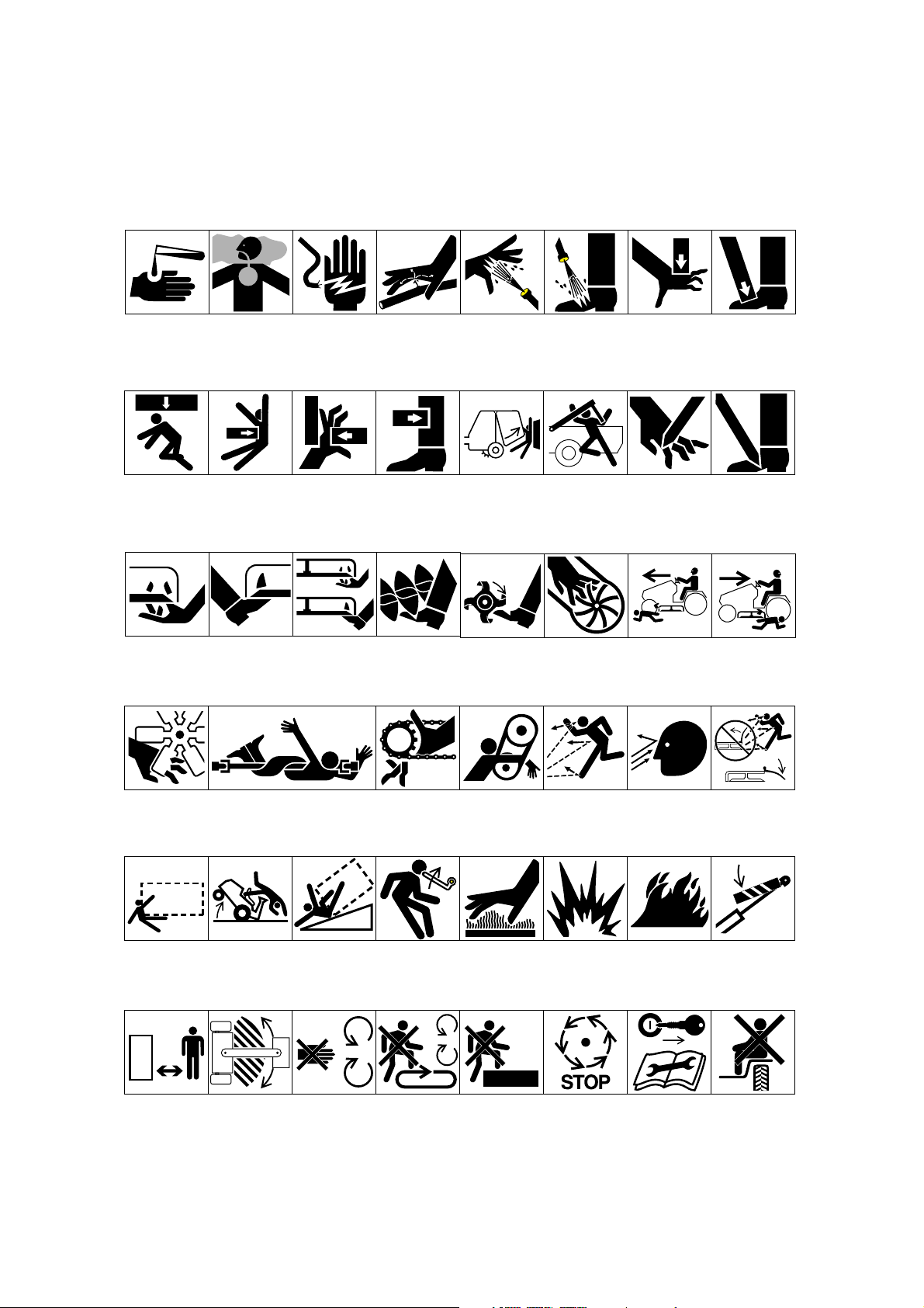
Symbol Glossary
Caustic liquids,
chemical burns to
fingers or hand
Poisonous
fumes or toxic
gases, asphyxiation
Electrical shock,
electrocution
High pressure
fluid, injection
into body
High pressure
spray, erosion of
flesh
High pressure
spray, erosion of
flesh
Crushing of
fingers
or hand,
force
applied from
above
Crushing of
toes or foot, force
applied from above
Crushing of
whole body,
applied from
above
Crushing of
torso, force
applied from side
Crushing of fingers
or hand/, force
applied from side
Crushing of
whole body
Crushing of
head, torso and
arms
Cutting of
fingers or hand
Cutting of footCrushing of leg,
force applied
from side
Severing of
fingers or hand,
mower blade
Severing of
toes or foot,
mower blade
Severing of
toes or fingers,
rotary mower
blade
Cutting or
entanglement of
foot, rotating auger
Severing of
foot, rotating
knives
Severing of
fingers or hand,
impeller blade
Dismemberment, front engine
mower in forward
motion
Dismemberment, front engine
mower in rearward
motion
Severing of
fingers or hand,
engine fan
Whole body entanglement,
implement input drive line
Fingers or
hand entanglement, chain
drive
Hand & arm
entanglement,
belt drive
Thrown or flying
objects, whole
body exposure
Thrown or
flying objects,
face exposure
Thrown or flying
objects, rotary
mover
Runover/backover, vehicle
Machine
tipping, riding
mower
Machine rollover,
ROPS (rear
engine mower)
Stored energy
hazard, kickback
or upward motion
Hot surfaces,
burns to fingers
or hands
Explosion Fire or open
flame
Secure lifting
cylinder with locking
device before getting
in hazardous area
Do not step on
loading platform
if PTO is connected to tractor &
engine is running
Do not step Wait until all
machine components have
completely
stopped before
touching them
Shut off engine
& remove key
before performing maintenance
or repair work
Stay a safe
distance from
the machine
Stay clear of
articulation area
while engine is
running
Do not open
or remove safety
shields while
engine is
running
Riding on this
machine is allowed
only on a passenger seat & only if the
driver’s view is not
hindered
Page 8
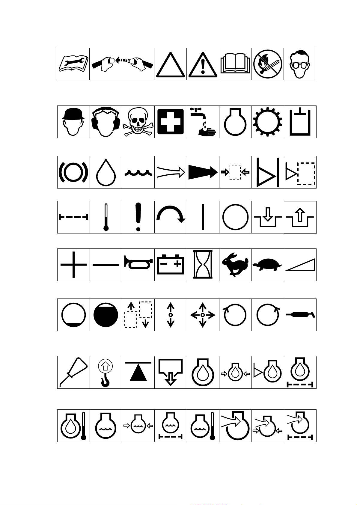
7
Consult technical
manual for proper
service
procedures
Fasten seat
belts
Safety alert
triangle
Outline safety
alert symbol
Read operator’s
manual
Fire, open light
and smoking
prohibited
Eye protection
must be worn
Head protection
must be worn
Brake system
Filter Temperature Failure/
Plus/increase/
positive polarity
Hearing
protection must
be worn
Oil Coolant (water) Intake air Exhaust gas Pressure Level indicator Liquid level
Minus/decrease/
negative polarity
Caution, toxic
risk
Malfunction
Horn
Flush with water Engine Transmission Hydraulic systemFirst aid
Start switch/
mechanism
Battery charging
condition
Hourmeter/
elapsed operating
hours
On/start Off/stop Engage
Fast Slow Continuous
Disengage
variable, linear
Volume empty Volume full Machine travel
Oil lubrication
point
Engine lubricating
oil temperature
Lift point Jack or
Engine coolant
direction,
forward/
rearward
support point
Engine coolant
pressure
Control lever
operating
direction, dual
direction
Draining/
emptying
Engine coolant
filter
Control lever
operating
direction, multiple
direction
Engine lubricating oil
Engine coolant
temperature
Clockwise
rotation
Engine
lubricating
oil pressure
Engine intake/
combustion air
Counter-clockwise rotation
Engine lubricating
oil level
Engine intake/combustion air pressure
Grease
lubrication
point
Engine lubricating
oil filter
Engine intake/air
filter
Page 9
8
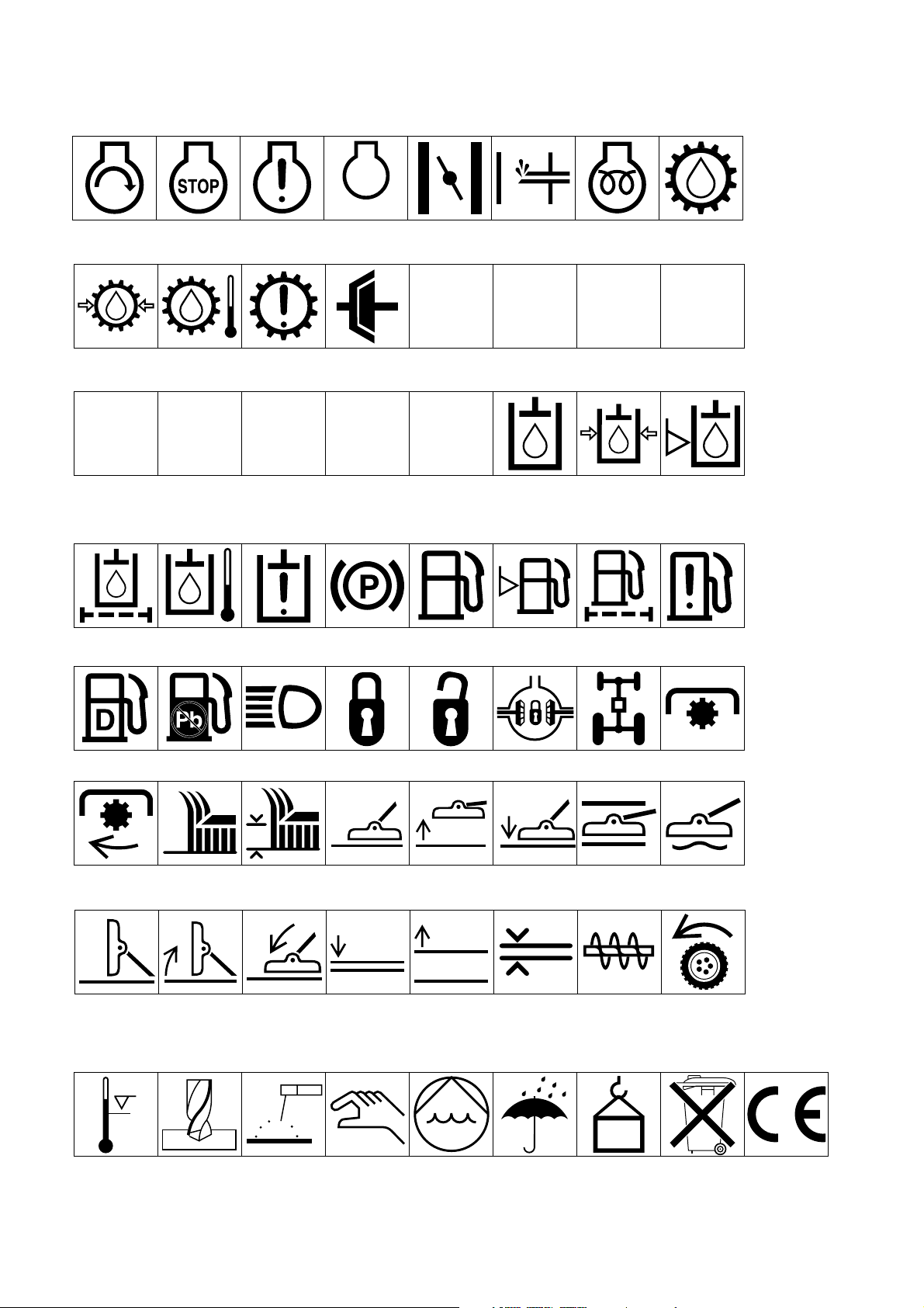
Engine start Engine stop Engine failure/
Transmission
oil pressure
Transmission
oil temperature
malfunction
Transmission
failure/malfunction
RP 2 31
Reverse
Park First gear
n/min
Engine rotational
speed/frequency
Choke Primer (start aid) Electrical preheat
(low temperature
start aid)
Transmission
oil
NHLF
Clutch Neutral High Low Forward
Second gear
Third gear (other #'s
may be used until the
maximum # of forward
gears is reached.)
Hydraulic oil
Hydraulic oil
pressure
Hydraulic oil
level
Hydraulic oil
filter
Power Take-Off,
rotational speed
Cutting unit,
transport
position
Hydraulic oil
temperature
Blade cutting
element
Cutting unit,
raise to transport
position
Hydraulic oil
failure/malfunction
Blade cutting
element, height
adjustment
Cutting unit,
lower to transport
position
Parking brake Fuel
Lock Unlock Differential lock 4-Wheel drive Power Take-OffDiesel fuel Unleaded fuel Headlights
Attachment
lower
Cutting unit Cutting unit,
raise
Attachment
raise
Fuel level
Cutting unit,
lower
Spacing distance Snow thrower,
Fuel filter Fuel system
Cutting unit,
hold
collector auger
failure/malfunction
Cutting unit,
float
Traction
Above working
temperature
range
Drilling Manual metal
arc welding
Manual Water pump Keep dry Weight Do not dispose
in the garbage
CE logo
Page 10

9
Specifications
Traction Unit
Engine: Peugeot, four-cycle, four-cylinder, 1.9 liter
(1,900 cc) displacement, liquid-cooled diesel engine.
23.5:1 compression ratio. Low idle—1,600 rpm, high
idle—2,800±30 rpm. Oil capacity is 5 l (5.3 quarts) with
filter.
Cooling System: Capacity is 13.2 l (3.5 gal) of 50/50
mixture of Peugeot recommended anti-freeze.
Fuel System: Capacity is 45.2 liter (12 gallon) of #1 or
#2 diesel fuel.
Hydraulic System: Reservoir capacity is 24.6 liters
(6.5 gallon). Replaceable spin-on filter element.
Traction System: Ground speed: Low Range; 0–10.5
kmh, 0–6.5 mph (0–5.5 mph. with mechanical speed
limiter interlock) forward and 0–4.8 kmh, 0–3 mph
reverse. High Range: 0–24.1 kmh, 0–15 mph (0–20
kmh, 0–12.4 m.p.h. with mechanical speed limiter
interlock) forward and 0–8 kmh, (0–5 mph) reverse.
Front Axle: Two-speed axle is designed to withstand
heavy-duty slope operation and side loading. Separate
mowing and transport selections for faster and more
efficient machine operation. Neutral position allows
easy towing.
Rear Axles: Two-Wheel Drive—The large diameter
wheel spindles are designed for durability and long
wear, yet provide superior stability and maneuverability.
Four-Wheel Drive—Heavy-duty, agricultural type.
Hydraulic drive with “on demand” bi-directional clutch
and balanced weight distribution provides superior
traction on hillsides.
Tires/Wheels: High flotation turf tread tires on demountable rims. Front tires: (2) 26 x 12.0-12, 8 ply.
Rear tires: (2) 20 x 10.0-10, 6 ply. Tire pressure 138 kPa
(20 psi).
Seat: Adjustable fore and aft travel and weight.
Diagnostic System: Test ports for: forward and reverse
traction (2-wheel drive), front and rear axle motors (4
wheel drive), lift and counterbalance circuit, steering
circuit and charge circuit.
Steering System: Automotive type, full power.
Brakes: Totally enclosed, non asbestos, dry multi-disc
14.3 cm individual wheel and parking brakes on front
traction wheels. Brakes controlled by individual pedals
operated by the left foot. Dynamic braking through
closed-loop hydrostatic drive.
Electrical System: 12-volt battery with 650 cold
cranking Amps @ –18°C (0° F). 55-amp alternator,
ammeter, starter, key switch and automatic temperature
controlled glow plug controller. Separately-fused run,
deck and instrument/accessory circuits.
Interlock System: Stops the engine if operator gets off
the seat while the cutting deck drive switch is engaged
or the traction pedal is forward or reverse. Prevents the
engine from starting unless the traction pedal is in
neutral and the cutting deck is disengaged. Prevents the
cutting deck from operating unless the axle shift is in
LO range. The engine will stop if the machine comes
out of neutral with the parking brake set.
Warning Lights:
Glow plug indicator
Engine oil pressure warning
Engine coolant temperature warning
Charge indicator
Water in fuel
Low-water indicator
Indicators:
Engine coolant temperature gauge
Fuel gauge
Hour meter
General Specifications (approx.):
Overall Length:
With the deck installed 340 cm (134 in.)
Overall Width:
Transport 190.5 cm (75 in.)
Mowing 323 cm (127 in.)
Height:147 cm (58 in.)
With rollover protection
system installed 208 cm (82 in.)
Wheel Tread:
(Front) 129.5 cm (51 in.)
(Rear) 104 cm (41 in.)
Page 11

10
Wheel Base: 132 cm (52 in.)
Dry Weight:
2-Wheel Drive 1,418 kg (3,800 lb)
4-Wheel Drive 1,455 kg (3,900 lb)
Optional Equipment
Broom Kit Contact Your Local Toro Distributor
Snowthrower Contact Your Local Toro Distributor
Roll-Over Protection Kit, Contact Your Local Toro
Distributor (Standard on Model 30455)
4-Post Canopy KitContact Your Local Toro Distributor
Spark Arrestor Muffler Part No. 94-5637
Segmented Wheel Kit, Part No. 76-1880
Brake Light Kit, Part No. 92-7763
Windshield Kit Contact Your Local Toro Distributor
Cruise Control Kit Model No. 30485
Road Light Kit Model No. 30471
Mulcher Kit Model No. 30475
Cab Contact your local Toro distributor
Additional Weights Contact your local Toro distributor
Low Seat Option Contact your local Toro distributor
Specifications and design subject to change without
notice.
Page 12

11
Before Operating
Check the Engine Oil
Crankcase capacity is 5 liters (5.3 qt) with filter.
1. Park the machine on a level surface. Release the
hood latch and open the hood.
Figure 1
1. Hood latch
2. Remove the dipstick from the tube cap, wipe it
clean and reinstall the dipstick into the tube cap.
Pull it out again and check the oil level on the
dipstick: The oil level must always be in the notch
area on the dipstick.
Figure 2
1. Dipstick/tube cap
3. If the oil level is low, remove the tube cap and add
SAE 10W–30 CD oil until the level reaches the top
of notch on the dipstick. DO NOT OVERFILL.
4. Install the oil tube cap.
5. Close the hood and secure the latch.
Check the Cooling System
Capacity of the system is 13.2 liters (3.5 gal).
1. Park the machine on a level surface. Release the
hood latch and open the hood.
2. Check the coolant level. The coolant level should
be up to or above the mounting tabs on the
degasser tank, when the engine is cold.
Figure 3
1. Degasser tank
3. If the coolant is low, remove the degasser tank cap
and add a 50/50 mixture of water and Peugeot
recommended anti-freeze (Toro Part No. 93-7213).
Do not use water only or alcohol/ methanolbased coolants.
Do not remove the black plastic cap
on the degasser tank.
4. Install the degasser tank cap.
5. Close the hood and secure the latch.
Fill the Fuel Tank
1. Park the machine on a level surface. Release the
hood latch and open the hood.
2. Remove the fuel tank cap.
Important
1
1
1
Before servicing or making adjustments to the
machine, stop the engine and remove the key from the
switch
CAUTION
Page 13

12
Figure 4
1. Fuel tank cap
3. Fill the tank to no more than one inch below the
bottom of the filler neck with No. 2 diesel fuel. DO
NOT OVER FILL. Then install the cap.
Note: For temperatures below 0° C (32° F), No. 1
diesel fuel or a blend should be used.
4. Close the hood and secure the latch.
Check Hydraulic Circuit Oil
The machine’s reservoir is filled at the factory with
approximately 24.6 l (6.5 gallons) of high-quality
hydraulic fluid. Check the level of hydraulic fluid before
the engine is first started and daily thereafter.
Appropriate hydraulic oils are listed below.
The following list is not all-inclusive. Hydraulic fluids
produced by other manufacturers may be used if they
can be cross referenced to find an equivalent to the
products listed. Toro will not assume responsibility for
damage caused by improper substitutions, so use only
products from reputable manufacturers who will stand
behind their recommendation.
Multigrade Hydraulic Fluid—ISO VG 46
Normal Climate: 0 (–18° C) to 110° F (43° C)
Mobil DTE 15M
Amoco Rykon Premium ISO 46
Chevron Rykon Premium Oil ISO 46
Conoco Hydroclear AW MV46
Exxon Univis N46
Pennzoil AWX MV46
Shell Tellus T 46
Texaco Rando HDZ 46
: The ISO VG 46 Multi-grade fluid has
been found to offer optimal performance in a wide range
of temperature conditions. For operation in consistently
high ambient temperatures, 65° F (18° C) to 120° F (49°
C), ISO VG 68 hydraulic fluid may offer improved
performance.
Hydraulic Fluids—ISO VG 68
Mobil DTE 26
Amoco Rykon AW No. 68
Chevron Hydraulic Oil AW ISO 68
Conoco Hydroclear AW 68
Exxon Nuto H 68
Pennzoil AW Hydraulic Oil 68
Shell Tellus 68
Texaco Rando HD 68
Note: Many hydraulic fluids are almost colorless,
making it difficult to spot leaks. A red dye additive for
the hydraulic system oil is available in 2/3 oz. (20 ml)
bottles. One bottle is sufficient for 4–6 gal (15–22 1) of
hydraulic oil. Order part no. 44-2500 from your
authorized Toro distributor. Not recommended for
biodegradable fluid (use food coloring).
1. Park the machine on a level surface and stop the
engine. Make sure the machine has been operated
so the oil is warm. Release the hood latch and open
the hood. Check the oil level by viewing the sight
gauge. If oil is visible in the gauge, the oil level is
sufficient.
2. If the oil level is not visible in the gauge, remove
the cap from the hydraulic oil reservoir and slowly
add a high-quality hydraulic oil until the level
reaches the middle (maximum) of the sight gauge.
DO NOT OVER FILL.
: To prevent system contamination,
Important
Important
1
Because diesel fuel is highly flammable, use
caution when storing or handling it. Do not
smoke while filling the fuel tank. Do not fill the
fuel tank while the engine is running, hot, or
when the machine is in an enclosed area. Always
fill the fuel tank outside and wipe up any spilled
diesel fuel before starting the engine. Store the
fuel in a clean, safety-approved container and
keep the cap in place. Use diesel fuel for the
engine only; not for any other purpose.
DANGER
Page 14

13
clean the tops of hydraulic oil containers before
puncturing. Make sure the pour spout and funnel
are clean.
3. Install the reservoir cap, close the hood and secure
the latch.
Figure 5
1. Sight gauge
2. Hydraulic reservoir cap
Check the Front Axle Oil Level
The front axle is shipped from the factory filled with
SAE 80–90 weight gear lubrication. However, check the
level before the engine is first started and every 50 hours
thereafter. Capacity is 378cl (128 oz.). Check daily for
signs of oil loss.
1. Park the machine on a level surface.
2. Remove the access panel (Fig. 6), in the front of
the seat, to expose the front axle/dipstick.
3. Unscrew the dipstick cap (Fig. 7) from the filler
neck and wipe it with a clean cloth. Screw the
dipstick cap finger tight onto the filler neck.
Unscrew the dipstick and check the level of
lubricant. If the level is not within 12mm (
1
⁄2 in.)
from the groove in the dipstick, add enough to raise
the level to the groove mark. DO NOT OVERFILL
by more than 12mm (
1
⁄2 inch) above the groove.
Figure 6
1. Access panel
4. Screw the dipstick filler cap finger-tight onto the
filler neck. It is not necessary to tighten the cap
with a wrench.
Figure 7
1. Dipstick cap
Check the Rear Axle Lubricant
The rear axle is shipped from the factory filled with
SAE 80–90 weight gear lubrication. However, check the
level before the engine is first started and every 50 hours
thereafter. Capacity is 237cl (80 oz).
1. Position the machine on a level surface.
2. Clean area around the (3) check plugs, (1) on each
end and (1) in the center (Fig. 8).
3. Remove the check plugs and make sure lubricant is
up to bottom of hole. If level is low, add enough
lubricant to bring the level up to the bottom of the
check plug holes.
1
2
1
1
Page 15

14
Figure 8
1. Vent/fill plug
2. Check plug (3)
Figure 9
1. Check/fill plug
Check Bi-Directional Clutch
Lubricant
The Bi-directional Clutch is shipped from the factory
filled with Mobil DTE 15 M anti-wear hydraulic fluid.
However, check the level before the engine is first
started and every 50 hours thereafter. Capacity is 8 oz.
Check daily for signs of oil loss.
1. Position the machine on a level surface.
2. Remove the check/fill plug from the clutch housing
and make sure lubricant is up to bottom of the hole.
If the level is low, add enough lubricant to bring the
level up to the bottom of the check/fill plug hole.
Note: Do not use gear lube in the clutch housing.
Figure 10
1. Clutch housing
2. Check/fill plug
3. Drain plug
Check Tire Pressure
The tires are over-inflated for shipping. Therefore,
release some of the air to reduce the pressure. Correct
air pressure in the front and rear tires is 138 kPa (20
psi).
: Maintain even pressure in all tires to
assure a good quality-of-cut and proper machine
performance. DO NOT UNDER INFLATE.
Check the Torque of Wheel Nuts
Or Bolts
Important
1
1
3
2
1
2
Torque the front wheel nuts to 45–55 ft-lb and the rear
wheel nuts or bolts to 85–100 ft lb after 1–4 hours of
operation and again after 10 hours of operation and
every 200 hours thereafter. Failure to maintain correct
torque could result in failure or loss of the wheel and
may result in personal injury.
WARNING
Page 16

15
Controls
Cutting Unit Engagement Switch (Fig. 11)—Used to
start and stop cutting unit operation. Lift switch and
move forward to actuate the cutting unit. Center deck
will engage first followed by wing decks engaging
approximately one second later.
Figure 11
1. Cutting unit engagement switch
2. Glow plug indicator
3. Charge indicator
4. Key switch
5. Throttle control
6. Cutting unit lift control
7. Coolant temperature gauge
8. Fuel gauge
9. Low-water indicator
10. Engine oil pressure warning light
11. Engine coolant temperature warning light
12. Water-in-fuel warning light
Glow Plug Indicator (Fig. 11)—Automatically actuates
proper glow period when the ignition key is turned to
ON. Illuminates when the glow plugs are actuated.
When the glow plugs are heated sufficiently, light goes
off indicating the engine is ready to start.
Charge Indicator (Fig. 11)—Illuminates when the
system charging circuit malfunctions.
Key Switch (Fig. 11)—Three positions: OFF, ON and
START. Turn the key to START and release it when the
engine begins running. To stop the engine, turn the key
to OFF.
Throttle Control (Fig. 11)—Move control forward to
increase the engine speed, backward to decrease speed.
Cutting Unit Lift Controls (Fig. 11)—The two outside
levers raise and lower the wing cutting units. The center
lever raises and lowers the whole cutting unit. The
engine must be running to lower the cutting unit. When
wing cutting units are raised higher than 15°, their
blades automatically disengage. To lower the cutting
unit, just touch the levers momentarily.
Coolant Temperature Gauge (Fig. 11)—Shows the
temperature of engine coolant.
Fuel Gauge (Fig. 11)—Shows the amount of fuel in the
tank.
Low-Water Indicator (Fig. 11)—Indicates low water
level in the cooling system.
Engine Oil Pressure Warning Light (Fig. 11)—
Indicates dangerously low engine oil pressure.
Engine Coolant Temperature Warning Light (Fig.
11)—The red light illuminates and the engine stops
when temperature of the coolant exceeds 110° C
(230° F).
Water-In-Fuel Indicator (Fig. 11)—Indicates when
there is water in the fuel.
Seat (Fig. 12)—Seat adjusting lever on the left side of
the seat allows 10cm (4-inch) fore and aft adjustment.
The seat adjusting knob on the front of the seat, adjusts
the seat for operator’s weight.
Figure 12
1. Seat adjusting lever
2. Seat adjusting knob
Traction Pedal (Fig. 13)—Controls forward and
reverse operation. Depress the top of the pedal to move
forward and the bottom to move backward. Ground
speed depends on how far the pedal is depressed. For
no load, maximum ground speed, fully depress the pedal
while the throttle is in FAST. For maximum power
under load or when going uphill, keep the engine rpm
high by having the throttle in FAST and the traction
pedal partially engaged. If engine rpm begins to
decrease due to load, gradually reduce the traction pedal
pressure until engine speed is increased.
6
4
1
3
2
10
5
11
7
8
12
9
2
1
Page 17

16
To stop, reduce foot pressure on the traction pedal and
allow it to return to the center position. On extreme
downhill slopes, apply pressure to REVERSE side of
the pedal, or operate with heel on REVERSE and toe on
FORWARD portion of the pedal.
Figure 13
1. Traction pedal
2. Axle shift lever
3. Lockout knob
Axle Shift Lever (Fig. 13)—Located on the right side
of console, the lever selects the front drive mode. Pull
out the lock-out knob, move the lever rearward for
mowing operation and forward for transport operation,
then release the knob to lock the selection. The lever
must be in LO position to mow. Middle position (N) is
for towing.
IMPORTANT: Lever must be in LO to operate in 4wheel drive.
CAUTION: The machine must be on a flat surface
and the brakes engaged when shifting the axle from
HI to LO.
Brake Pedals (Fig. 14)—Two foot pedals at the lower
left operate individual wheel brakes for turning
assistance, parking and for better side hill traction. The
locking pin is for parking.
Figure 14
1. Brake pedals
2. Parking brake latch
3. Steering wheel tilt lever
Parking Brake Latch (Fig. 14)—A knob on the left
side of console actuates the parking brake lock. To
engage the parking brake, connect the pedals with the
locking pin, push down on both pedals and pull the
parking brake latch out. To release the parking brake,
depress both pedals until the parking brake latch
retracts.
Steering Wheel Tilt Lever (Fig. 14)—The lever on the
left side of console lets the steering wheel to be adjusted
for operator comfort.
Transport Latches (Fig. 15)—Four latches secure the
cutting unit and wings in upright position for transport.
Figure 15
1. Transport latch (4)
Hour Meter (Under Hood)—Shows total hours that the
machine has been operated.
1
1
3
2
1
3
2
Page 18

17
Operation
Starting and Stopping
1. Sit on the seat and keep your foot off the traction
pedal. Assure the parking brake is engaged, the
traction pedal is in NEUTRAL and the cutting unit
engagement switch is in the DISENGAGED
position.
2. Turn the ignition switch to ON. When the glow
plug indicator light goes off, the engine is ready to
START.
3. Turn the ignition key to START. Release the key
when the engine starts.
4. To stop, disengage and move all controls to
NEUTRAL and set the parking brake. Turn the key
to OFF and remove it from switch. Raise and latch
all the cutting units in transport position.
Priming the Fuel System
: The fuel system may need to be primed
when a new engine is started for the first time, if it runs
out of fuel or if maintenance is performed on the fuel
system.
1. Unlatch and raise the hood.
2. Insert a 48 mm (
3
⁄16) hose over bleed screw and run
other end into a container to catch fuel.
3. Loosen the fuel filter/water separator bleed screw
(Fig. 16) a few turns. Pump the priming plunger
until a steady stream of fuel comes out of the hole
in the bleed screw. When fuel stops foaming,
tighten the bleed screw during the down stroke of
the priming plunger. Wipe up any spilled fuel.
Note: Priming the fuel filter without opening the
bleed screw may damage the priming plunger.
4. Pump the priming plunger until resistance is felt.
Try to start the engine. If the engine does not start
repeat step 3.
Figure 16
1. Hood plunger
2. Bleed screw
Note: It may be necessary to bleed the air out of
the fuel line between the fuel filter/water separator
and the injection pump. To do this, loosen the
fitting on the injection pump (Fig. 17) and repeat
bleeding procedure.
Figure 17
1. Injection pump fitting
Checking the Interlock System
The purpose of the interlock system is to prevent the
engine from cranking or starting unless the traction
pedal is in NEUTRAL and the cutting unit engagement
switch is DISENGAGED. Also, the engine will stop
when the cutting unit engagement switch is engaged or
the traction pedal is depressed with the operator off the
seat.
Important
1
2
1
Page 19

18
1. In a wide open area free of debris and bystanders,
lower the cutting unit to the ground. Stop the
engine.
2. Move the cutting unit engagement switch to
DISENGAGED and remove your foot from the
traction pedal so it is fully released.
3. Turn the ignition key to START. The engine should
start. If the engine starts, go to step 4. If the engine
does not start, there may be a malfunction in the
interlock system.
4. Rise from the seat and engage the cutting unit
engagement switch while the engine is running.
The engine should stop within 2 seconds. If the
engine stops, the switch is operating correctly; go
to step 5. If the engine does not stop, there is a
malfunction in the interlock system.
5. Rise from the seat and depress the traction pedal
while the engine is running and the cutting unit
engagement switch is DISENGAGED. The engine
should stop within 2 seconds. If the engine stops,
the switch is operating correctly; continue
operation. If the engine does not stop, there is a
malfunction in the interlock system.
Operating Characteristics
Familiarization—Before mowing grass, practice
operating the machine in an open area. Start and stop
the engine. Operate in forward and reverse. When you
feel familiar with the machine, practice operating
around trees and obstacles. Also drive up and down
slopes at different speeds.
Warning: When operating a 4-wheel drive machine,
always use the seat belt and roll-over protection system
together and have the seat pivot retaining pin installed.
Another characteristic to consider is the operation of the
brake pedals. The brakes can be used to help turn the
machine. However, use them carefully, especially on
soft or wet grass because the turf may be torn
accidentally. Another benefit of the brakes is to maintain
traction. For example: When operating on a side hill, the
uphill wheel slips and loses traction. If this situation
occurs, depress the uphill brake pedal gradually and
intermittently until the uphill wheel stops slipping, thus,
increasing traction on the downhill wheel.
Warning System—If a warning light comes on during
operation, stop the machine immediately and correct the
problem before continuing operation. Serious damage
could occur if the machine is operated with a
malfunction.
Mowing—When you are at the area to be mowed,
release the cutting unit transport latches. Move the axle
shift lever rearward to Mow and the throttle to FAST so
the engine is running at maximum speed. Lift the
engagement switch and move forward to engage the
cutting units.
Curbside Mowing—To reduce the possibility of
foreign debris escaping from under the cutter deck while
mowing at or near a road or walkway curb, always keep
the outside edge of the cutter deck inside the curb. The
cutter deck caster wheels should not be guided along the
top of the curb; this could cause the cutter deck to hang
over the edge of the curb. Never allow the edge of the
cutter deck to extend over the edge of the curb while the
blades are turning. Always stop mowing and disengage
the mower blades when encountering pedestrians or
other bystanders/ passers-by.
Note: The cutting deck is equipped with a breakaway
system to prevent wing decks from being damaged if a
solid object is struck. If a wing deck strikes a solid
object and unlatches from the center cutting deck, raise
and lower the wing deck to reset in operating position.
Transport—When mowing is complete, disengage the
cutting unit and raise it by pulling back on the cutting
unit lift control levers. Hold the levers back until the
cutting unit is fully raised. Never raise the cutting
deck when it is engaged. Lock the cutting unit in place
with transport latches. Move the axle shift lever forward
to HI. When driving from one area to another, always
shift the axle to LO before encountering a slope. Never
shift from HI to LO while on a slope. Stop the machine
on a flat surface, engage the brakes and shift before
climbing the slope. Be careful when driving between
objects so you do not accidentally damage the machine
The interlock switches are for the operator’s
protection, so do not disconnect them. Check switch
operation daily to assure the interlock system is
operating. If a switch is defective, replace it before
operating. Regardless of whether the switches operate
correctly or not, replace them every two years to
assure maximum safety. Do not rely entirely on safety
switches—use common sense!
CAUTION
Page 20

19
or the cutting unit.
Use extra care when operating the machine on
slopes. Drive slowly and avoid sharp turns on slopes
to prevent rollovers. The cutting unit must be
lowered when going downhill for steering control.
We recommend you use protective equipment, such as
protective equipment for eyes, ears, feet and head.
1. Caution
2. Wear hearing protection
Pushing Or Towing The Traction Unit—Use only a
rigid tow bar if it becomes necessary to tow the
machine. Make sure the axle shift lever is in NEUTRAL
position and only tow the machine forward. Use trailer
for normal transport. Move the axle shift lever to LO
position before loading the machine on a trailer.
Operating Tips
Mow When Grass Is Dry—Mow either in the late
morning to avoid the dew, which causes grass clumping
or in late afternoon to avoid the damage that can be
caused by direct sunlight on the sensitive, freshly
mowed grass.
Select the Proper Height-of-cut Setting To Suit
Conditions—Remove approximately 2.5 cm (one inch)
or no more than 1/3 of the grass blade when cutting. In
exceptionally lush and dense grass you may have to
raise your height-of-cut setting another notch.
Mowing In Extreme Conditions—Air is required to
cut and re-cut grass clippings in the mower housing, so
do not set the height-of-cut too low or totally surround
the housing by uncut grass. Try to have one side of the
mower housing free from uncut grass, allowing air to be
drawn into housing. When making an initial cut through
the center of an uncut area, operate the machine slower
and back up if the mower starts to clog.
Clippings Discharge—Although the deck has rear
discharge, some clippings are discharged toward the left
side. To avoid discharging undesirable clippings onto
pathways, roads, or other non-turf surfaces, mow with
the right side of the deck next to the pathway, road, or
other non-turf surface
Mow At Proper Intervals—Under most normal
conditions you’ll need to mow every 4–5 days. But
remember, grass grows at different rates at different
times. This means that to maintain the same height of
cut—which is a good practice—you’ll need to cut more
often in early spring; as the grass growth rate slows in
mid summer, cut it only every 8–10 days. If you’re
unable to mow for an extended period, mow first with
the height-of-cut at a high level; then mow again 2–3
days later with a lower height setting.
Always Mow With Sharp Blades—A sharp blade cuts
cleanly and without tearing or shredding the grass
blades. Tearing and shredding causes the grass to turn
brown at the edges which impairs growth and increases
susceptibility to diseases.
After Operating—To assure optimum performance,
clean the underside of the mower housings and under
the belt covers after each use. Use low pressure
compressed air only. Do not use water. If residue is
allowed to build up in the mower housings, cutting
performance will decrease.
This machine produces sound levels in excess of 85
dBA at the operator’s ear and can cause hearing loss
through long periods of exposure.
Wear hearing protection when operating this machine.
CAUTION
Page 21

20
Maintenance
Service Interval
Chart
1. Engine oil level/fill
2. Hydraulic oil level/fill
3. Front axle oil level/fill
4. Rear axle oil level
A. Fill
B. Check (2)
5. Coolant level/fill
6. Fuel diesel only
7. Grease points (23)
8. Radiator screen
9. Air filter service indicator
10. Water separator/fuel filter
11. Battery
12. Fan belt
13. Tire pressure
CHECK/FILL
Engine oil
Hydraulic circuit oil
Axle oil
Fuel filter
Primary air filter
Safety air filter
Fuel >0° C
Coolant
Fluid Type Capacity
Change Interval
Fluid Filter
SAE 15W-40 CD
Mobil DTE 15 M
SAE 80-90 E.P.
No. 2-D
No. 1-D
93-7213 50/50
Peugeot Anti-Freeze
5 L
24.6 L
53 L
13.25 L
100 hours
800 hours
800 hours
100 hours
800 hours
See service indicator
Drain and flush, 800 hours
Drain and flush, 1500 hours or two years, whichever
occurs first
400 hours
See operator’s manual
<0° C
Filter Part.
No.
74-7970 (A)
86-3010 (B)
76-5220 (C)
93-9162 (D)
93-9163 (E)
Page 22

21
Greasing (Fig. 18–26)
The traction and cutting units have grease fittings that
must be lubricated regularly with No. 2 General Purpose
Lithium Base Grease. If the machine is operated under
normal conditions, lubricate all grease fittings after
every 25 hours of operation. Lubricate all grease
fittings immediately after every washing, regardless of
interval listed.
The grease fittings that must be lubricated are: Lift arm
pivot (2), lift cylinder (4), brake arm pivots (2) (Fig.
18); brake pivot (1), brake pivots (2) (Fig. 19); traction
pedal pivot (1) (Fig. 20); engine to pump drive shaft (2)
(Fig. 21 & 22); traction adjuster (1) (Fig. 23); P.T.O.
Bearing (Fig. 24); center pivot (1) (Fig. 25); tie rod
assembly (2), axle knuckles (2) cylinder ends (2) (Fig.
26).
1. Wipe grease fittings clean before lubricating.
2. Pump grease into fitting.
3. Wipe up excess grease.
Fig. 18
Fig. 19
Fig. 20
Fig. 21
Fig. 22
Page 23

22
Fig. 23
Fig. 24
Fig. 25
Fig. 26
Page 24

23
Maintenance Procedure Maintenance Interval & Service
✝ Initial break in at 10 hours
‡ Initial break in at 50 hours
■ If the indicator shows red
✝Inspect engine fan belt
Inspect engine timing belt (see note below)
Drain and clean the fuel tank
Change hydraulic oil
‡Change hydraulic oil filter
Change front transaxle oil
Pack the rear axle bearings (2-wheel drive)
Change rear axle oil (4-wheel drive)
Change bi-directional clutch fluid (4-wheel drive)
Check rear wheel toe-in
Replace moving hydraulic hoses
Replace safety switches
Flush the cooling system and replace fluid
Replace PTO belts/cutter deck belts
■Service the air cleaner if the indicator shows red
Replace the fuel filter
Check front transaxle oil level
Check rear axle oil level (4-wheel drive)
Inspect fuel lines and connections
‡Check engine rpm (idle and full throttle)
✝Inspect PTO and cutting unit belts
‡ Check electric deck clutches adjustment
‡ Check electric PTO clutch adjustment
✝Torque wheel lug nuts
‡ Change engine oil and filter
Check battery level/cable connections
Inspect cooling system hoses
Inspect the air filter, dust cup and baffle
Lubricate all grease fittings
Check cutting unit gear box oil level
Every
400
hours
Every
800 hours
Every
200
hours
Every
100
hours
Every
50
hours
Minimum Recommended Maintenance Intervals
Recommendations:
Items are recommended every 1500 hours or
two years, whichever occurs first.
NOTE: Replace the timing belt, if worn, cracked or oil soaked. A new timing belt should be installed any
time the belt is removed or loosened.
Page 25

24
General Air Cleaner Maintenance
1. Check air cleaner body for damage that could
possibly cause an air leak. Replace a damaged air
cleaner body.
2. Service the air cleaner filters whenever air cleaner
indicator (Fig. 27) shows red or every 400 hours
(more frequently in extreme dusty or dirty
conditions). Do not over-service the air filter.
Figure 27
1. Air cleaner indicator
3. Be sure the cover is sealing around the air cleaner
body.
Servicing the Air Cleaner
1. Release the latches securing the air cleaner cover to
the air cleaner body. Separate the cover from the
body. Clean inside of the air cleaner cover.
2. Gently slide the primary filter (Fig. 28) out of the
air cleaner body to reduce the amount of dust
dislodged. Avoid knocking the filter against the air
cleaner body. Do not remove the safety filter.
Figure 28
1. Air cleaner latches
2. Dust cup
Figure 29
1. Air cleaner primary filter
3. Inspect the primary filter and discard if damaged
Do not wash or reuse a damaged filter.
: Never attempt to clean a safety filter
(located inside the primary filter). Replace the
safety filter with a new one after every three
primary filter services.
Washing Method
A. Prepare a solution of filter cleaner and water
and soak the filter element for about 15
minutes. Refer to directions on the filter
cleaner carton for complete information.
B. After soaking filter for 15 minutes, rinse it
with clear water. Maximum water pressure
must not exceed 276kPa (40 psi) to prevent
damage to the filter element. Rinse the filter
from the clean side to the dirty side.
C. Dry the filter element using warm, flowing air
71° C (160°F) max), or allow the element to
air dry. Do not use a light bulb to dry the filter
element because damage could result.
Important
Before servicing or making adjustments to the
machine, stop the engine and remove the key from the
switch.
WARNING
1
1
2
1
Page 26

25
Compressed Air Method
A. Blow compressed air from inside to the
outside of dry filter element. Do not exceed
689 kPa (100 psi) to prevent damage to the
element.
B. Keep the air hose nozzle at least 5cm from the
filter and move the nozzle up and down while
rotating the filter element. Inspect for holes
and tears by looking through the filter toward
a bright light.
5. Inspect the new filter for shipping damage. Check
the sealing end of the filter. Do not install a
damaged filter.
6. Insert the new filter properly into the air cleaner
body. Make sure the filter is sealed proper by
applying pressure to the outer rim of the filter when
installing it. Do not press on the flexible center of
the filter.
7. Reinstall the cover and secure the latches. Make
sure the cover is positioned with the TOP side up.
8. Reset the indicator (Fig. 27) if it is still showing
red.
Engine Oil and Filter
Change the oil and filter initially after the first 50 hours
of operation, thereafter change the oil and filter every
100 hours.
1. Remove the drain plug (Fig. 30) and let oil flow
into drain the pan. When oil stops flowing, install
the drain plug and a new plug seal.
2. Remove the oil filter (Fig. 31). Apply a light coat
of clean oil to the new filter seal before screwing it
on. DO NOT OVER-TIGHTEN.
Figure 30
1. Drain plug
Figure 31
1. Oil filter
3. Add 15W-40 CD oil to the crankcase. Capacity is
5.0 l (5.3 quarts) with filter.
Fuel System
Fuel Tank
Drain and clean the fuel tank every 800 hours of
operation or yearly, whichever comes first. Also, drain
and clean the tank if the fuel system becomes
contaminated or if the machine is to be stored for an
extended period. Use clean fuel to flush out the tank.
1
Page 27

26
Fuel Lines and Connections
Check lines and connections every 400 hours or yearly,
whichever comes first. Inspect for deterioration,
damage, or loose connections.
Draining Fuel Filter/Water Separator
Drain water or other contaminants from the fuel filter
water separator daily.
1. Place a clean container under the fuel filter.
Figure 32
1. Fuel filter/water separator
2. Drain screw
3. Primer plunger
2. Loosen the drain thumb screw on the side of the
fuel filter and press the primer plunger until only
fuel is evident draining into container.
3. Tighten the drain screw.
Changing Fuel Filter
Replace fuel filter if fuel flow becomes restricted, after
every 400 hours of operation or annually, whichever
comes first.
1. Unscrew the bottom filter cap from the filter
assembly. Remove the cap, gaskets, O-ring and
filter from the assembly. Note the position of the
gaskets and O-ring when disassembling from them
the filter.
2. Install new filter, gaskets, O-ring with the filter
assembly cap.
3. Prime the fuel system, refer to Priming the Fuel
System, p 17.
Engine Cooling System
1. Removing Debris—Remove debris from the rear
screen, oil cooler and radiator daily, clean more
frequently in dirty conditions. Use low-pressure
compressed air.
: Never spray water onto a hot engine
or onto electrical connections as damage may
occur.
A. Turn the engine off, release the hood latch and
raise the hood. Clean the engine area
thoroughly of all debris. Close the hood.
B. Unscrew the knobs and remove the rear screen
(Fig. 33). Clean the screen thoroughly.
Figure 33
1. Rear screen
C. Unscrew the knobs and pivot the oil cooler
rearward.
Clean both sides of the oil cooler and radiator
area thoroughly with low-pressure compressed
air. Open the hood and blow debris out
toward the back of the machine. Pivot the oil
cooler back into position and tighten the
Important
Because diesel fuel is highly flammable, use
caution when storing or handling it. Do not
smoke while filling the fuel tank. Do not fill the
fuel tank while the engine is running, hot, or
when the machine is in an enclosed area. Always
fill the fuel tank outside and wipe up any spilled
diesel fuel before starting the engine. Store the
fuel in a clean, safety-approved container and
keep the cap in place. Use diesel fuel for the
engine only; not for any other purpose.
DANGER
2
1
3
Page 28

27
knobs.
Note: The upper portion of the fan shroud may
be easily unbolted from the machine to
simplify cleaning.
D. Install the rear screen and tighten the knobs.
: Do not use water to clean the
engine, as damage may occur.
Figure 34
1. Oil cooler
2. Maintaining Cooling System—Capacity of the
system is 13 l (3.5 gal). Always protect the cooling
system with a 50/50 solution of water and Peugeot
recommended anti-freeze. DO NOT USE WATER
ONLY IN COOLING SYSTEM.
A. After every 100 operating hours, tighten the
hose connections. Replace any deteriorated
hoses.
B. After every 2 years or 1500 hours, drain and
flush the cooling system. Add anti-freeze
(refer to Check the Cooling System, p 11).
Engine Fan Belt
Check the condition and tension of fan the belt (Fig. 46)
frequently. Inspect the belt every 800 hours of
operation.
1. Proper tension will allow 6mm deflection on the
belt midway between the pulleys, when pressed
firmly with your thumb.
2. If deflection exceeds 6mm, loosen the alternator
mounting bolts. Adjust alternator belt tension by
adjusting the tension screw. Check deflection of
the belt again to assure tension is correct.
Figure 35
1. Fan belt
2. Adjusting screw
Engine Timing Belt
Inspect the engine timing belt every 800 hours of
operation or yearly.
1. Remove covers and check for a worn, cracked or
oil-soaked belt.
Note: A new belt should be installed any time a
belt is removed or loosened.
Changing Hydraulic Oil
Change the hydraulic oil filter initially after the first 50
hours of operation; thereafter change the hydraulic oil
and filter after every 800 operating hours. If oil
becomes contaminated, contact your local TORO
distributor because the system must be flushed.
Contaminated oil looks milky or black when compared
to clean oil.
1. Turn the engine off, release the hood latch and raise
the hood.
2. Remove the drain plug from the rear of the
reservoir and hydraulic line from front of reservoir
(Fig. 36) and let hydraulic oil flow into the drain
pan. Reinstall and tighten the plug and line when
hydraulic oil stops draining.
3. Fill the reservoir with approximately 24.6 l of
hydraulic oil. Refer to Check Hydraulic Circuit
Oil, p 12.
: Use only hydraulic oils specified.
Other fluids could cause system damage.
Important
Important
2
1
Page 29

28
Figure 36
1. Hydraulic Reservoir Drain
4. Install the reservoir cap, lower the hood and latch.
Start the engine and use all hydraulic controls to
distribute hydraulic oil throughout the system.
Also check for leaks. Then stop the engine.
5. With the wing decks raised, the center of the deck
down and the oil warm, look into the sight gauge
(Fig. 37). If hydraulic oil is not visible, add enough
oil to raise the level to the middle (maximum) of
the sight gauge. To prevent over filling, do not fill
if oil is cold. DO NOT OVER FILL.
Figure 37
1. Sight gauge
Replacing the Hydraulic Filter
Initially, change the filter after the first 50 operating
hours, thereafter, every 800 operating hours or annually,
whichever comes first.
Only the Toro replacement filter (Part No. 86-3010) can
be used in the hydraulic system.
: Use of any other filter may void the
warranty on some components.
1. Turn the engine off, release the hood latch and raise
the hood.
2. Clean the area around the filter mounting area
(Fig. 38). Place a drain pan under the filter and
remove the filter.
Figure 38
1. Hydraulic Filter
3. Lubricate the new filter gasket and fill the filter
with hydraulic oil.
4. Assure the filter mounting area is clean. Screw the
filter on until the gasket contacts the mounting
plate. Then tighten the filter one-half turn.
5. Start the engine and let it run for about two minutes
to purge air from the system. Stop the engine and
check the oil level. Also check for any leaks.
Checking Hydraulic Lines and
Hoses
Check hydraulic lines and hoses daily for leaks, kinked
lines, loose mounting supports, wear, loose fittings,
weather deterioration and chemical deterioration. Make
all necessary repairs before operating.
Important
2
1
Keep body and hands away from pin-hole leaks or
nozzles that eject high pressure hydraulic fluid. Use
cardboard or paper to find hydraulic leaks. Hydraulic
fluid escaping under pressure can penetrate skin and
cause injury. Fluid accidentally injected into the skin
must be surgically removed within a few hours by a
doctor familiar with this form of injury or gangrene
may result.
WARNING
1
1
Page 30

29
Hydraulic System Test Ports
The test ports are used to test the hydraulic circuits.
Check all pressures when engine is at full speed and
hydraulic oil is at normal operating temperature.
Contact your local Toro distributor for assistance.
1. Traction forward and reverse have a normal relief
setting of approximately 41,000 kPa (6000 psi).
2. Normal charge pressure is 689–965 kPa (100–140
psi).
Figure 39
1. Traction forward circuit
2. Traction reverse circuit
3. Cutting unit counterbalance normal setting is
approximately 4,100–4,400 kPa (600–650 psi) @
high idle and when oil is warm.
4. Lift circuit relief pressure is approximately
17,900–19,300 kPa (2600–2800 psi) when oil is
warm.
5. The steering circuit has a normal relief setting of
approximately 8,274 kPa (1200 psi) @ high idle
and warm oil.
6. Wing deck cutting unit Counterbalance normal
setting is approximately 2400–2700 (350–400 psi )
@ high idle and when oil is warm.
Figure 40
1. Charge pressure
Figure 41
1. Counterbalance/Lift circuit
2. Steering circuit
Figure 42
1. Counterbalance (wing decks)
Adjusting the Traction Drive for
Neutral
The machine must not creep when the traction pedal is
released. If it does creep, an adjustment is required.
1
Page 31

30
1. Park the machine on a level surface, shut the
engine off and move shift lever to HI. Depress
only the left brake pedal and engage the parking
brake.
2. Jack up the right side of the machine until the front
tire is off the shop floor. Support -the machine
with jack stands to prevent it from falling
accidentally.
3. Under the left side of the machine, loosen the
locknut on the traction adjustment cam.
Figure 43
1. Traction adjustment cam
2. Locknut
4. Start the engine and rotate the cam hex in either
direction until the wheel stops turning.
5. Tighten the locknut locking adjustment.
6. Stop the engine and release the right brake.
Remove the jack stands and lower the machine to
the shop floor. Test drive the machine to make sure
it does not creep.
Changing Front Axle Lubricant
After every 800 hours of operation the oil in the front
axle must be changed.
1. Position the machine on a level surface.
2. Clean the area around the drain plug (Fig. 44).
Figure 44
1. Front axle drain plug
3. Remove the plug, allowing oil to drain into a drain
pan.
4. After oil is drained, reinstall the drain plug into the
axle.
5. Fill the axle with lubricant; refer to Check Front
Axle Oil Level.
Changing Rear Axle Lubricant
After every 800 hours of operation the oil in the rear
axle must be changed.
1. Position the machine on a level surface.
2. Clean the area around the (3) drain plugs, (1) on
each end and (1) in the center (Fig. 45).
3. Remove the plugs, allowing oil to drain into a drain
pans.
4. After the oil has drained, apply some threadsealing compound on the drain plug threads and
reinstall it into the axle.
5. Fill the axle with lubricant; refer to Check Rear
Axle Lubricant, p .13.
The engine must be running so that final
adjustment of the traction adjustment cam can be
performed. To guard against possible personal
injury, keep hands, feet, face and other parts of
the body away from the muffler, other hot parts
of the engine, and other rotating parts.
WARNING
1
1
2
Page 32

31
Figure 45
1. Drain plugs (3)
Changing Bi-Directional Clutch
Lubricant
After every 800 hours of operation, the oil in the clutch
housing must be changed.
1. Position the machine on a level surface.
2. Remove the drain plug from the clutch housing
allowing fluid to drain into a drain pan.
Figure 46
1. Clutch housing
2. Check/fill plug
3. Drain plug
3. After fluid has drained, reinstall the drain plug.
4. Remove check/fill plug and add 237 cl (8 oz.) of
Mobil DTE 15 M anti-wear hydraulic fluid. Note:
Do not use gear lube in the clutch housing.
5. Install the check/fill plug.
Rear Wheel Toe In
After every 800 operating hours or annually, check rear
wheel toe-in.
1. Measure center-to-center distance (at axle height)
at the front and rear of the steering tires. Front
measurements must be within 3 mm of each other.
2. To adjust 4-wheel drive models (Fig. 48):
A. Remove the cotter pin and nut securing one of
the tie rod ball joints to the steering arm.
Remove the ball joint from the steering arm.
B. Loosen the clamp securing the ball joint to the
tie rod.
C. rotate the ball joint one revolution and re-
install it to the steering arm.
D. Inspect the toe-in and repeat adjustment if
required.
E. Tighten the clamp securing the ball joint to the
tie rod.
F. Torque the ball joint nut to 40 ft. lbs. and
install the cotter pin.
Figure 47
1. Tie rod clamps
Adjusting Service Brakes
Adjust the service brakes when there is more than
38mm of "free travel" of the brake pedal, or when the
brakes do not work effectively. Free travel is the
distance the brake pedal moves before braking
resistance is felt.
1. To reduce free travel of the brake pedals, tighten
the nut on the brake rod adjuster,
1
⁄2 turn at a time,
until you achieve the desired "free play" in the
1
3
2
1
1
Page 33

32
pedal.
Figure 48
1. Brake rod adjuster
Adjusting the PTO Belt
Re-tension the PTO belt (Fig. 49) initially after the first
10 hours of operation; thereafter, check condition and
tension of belt every 100 hours. Replace the belt after
every 1500 hours of operation.
1. Remove (2) screws securing the belt cover to the
adapter plate and the screw the securing belt cover
to the tab on the spring anchor. Remove the cover.
Figure 49
1. Belt cover
2. Adapter plate
2. Loosen the (3) flange screws and flange nuts
securing the adapter plate to the clutch plate.
3. Insert the end of a
1
⁄2-inch drive, 51cm long, torque
wrench into square hole in clutch plate. With the
wrench handle parallel to the ground, pull the
wrench upward until 244Nm (180ft-lbs.) of torque
is applied to the tension belt.
4. Tighten the flange screws and flange nuts.
5. Reinstall the belt cover with screws previously
removed.
Figure 50
1. PTO belt
2. Adapter plate
3. Square hole
Adjusting the Clutch
The PTO clutch is adjustable to ensure proper
engagement and blade braking. Check clutch
adjustment initially after the first 10 hours of operation,
thereafter, check every 200 hours.
1. To adjust the clutch, tighten or loosen the locknuts
on the flange studs.
2. Check adjustment by inserting a feeler gauge
through the slots next to the flange studs.
Figure 51
1. Clutch
2. Flange studs
1
1
2
1
2
3
1
2
Page 34

33
3. The proper disengaged clearance between the
clutch plates is 0.2–0.5mm. It will be necessary to
check this clearance at each of the three slots to
ensure the plates are parallel to each other.
Battery Care
: Before welding on the machine,
disconnect the ground cable from the battery to prevent
damage to the electrical system.
Note: Check battery condition weekly or after every 100
hours of operation. Keep the terminals and battery case
clean because a dirty battery will discharge slowly. To
clean the battery, wash the entire case with solution of
baking soda and water. Rinse with clear water. Coat the
battery posts and cable connectors with Grafo 11 2X
(skin-over) grease (Toro Part No. 505-47) or petroleum
jelly to prevent corrosion.
Fuses
There are four fuses in the machine’s electrical system.
They are located inside control panel.
Figure 52
1. ACC fuse (5 amp)
2. Relay fuse (5 amp)
3. Deck fuse (30 amp)
4. Run fuse (15 amp)
Preparation for Seasonal Storage
Traction Unit
1. Thoroughly clean the traction unit, cutting units
and the engine.
2. Check the tire pressure. Inflate all tires to 138 kPa
(20 psi).
3. Check all fasteners for looseness; tighten as
necessary.
4. Grease or oil all grease fittings and pivot points.
Wipe up any excess lubricant.
5. Lightly sand and use touch-up paint on painted
areas that are scratched, chipped, or rusted. Repair
any dents in the metal body.
6. Service the battery and cables as follows:
a. Remove the battery terminals from the battery
posts.
b. Clean the battery, terminals, and posts with a
wire brush and baking soda solution.
c. Coat the cable terminals and battery posts with
Grafo 112X skin-over grease (Toro Part No.
505-47) or petroleum jelly to prevent
corrosion.
d. Slowly recharge the battery every 60 days for
24 hours to prevent lead sulfation of the
battery.
Engine
1. Drain the engine oil from the oil pan and replace
the drain plug.
2. Remove and discard the oil filter. Install a new oil
filter.
3. Refill the oil pan with 5 l of SAE15W-40 CD
motor oil.
4. Start the engine and run at idle speed for
approximately two minutes.
5. Stop the engine.
6. Flush the fuel tank with fresh, clean diesel fuel.
Important
Page 35

34
7. Resecure all fuel system fittings.
8. Thoroughly clean and service the air cleaner
assembly.
9. Seal the air cleaner inlet and the exhaust outlet with
weatherproof tape.
10. Check anti-freeze protection and add a 50/50
solution of water and Peugeot recommended antifreeze (Toro part No. 93-7213) as needed for
expected minimum temperature in your area.
Cutting Unit
1. Check blades and tighten blade bolts to
115–149Nm (85-110 ft-lb.).
2. Check and lubricate caster arm bushings.
3. Check and lubricate caster wheel bearings (if so
equipped). Tighten caster wheel nuts to 190–224
kPa (140–165 ft-lb.).
4. Check all fasteners for looseness; tighten as
necessary.
5. Grease or oil all grease fittings and pivot points.
Wipe up any excess lubricant.
6. Lightly sand and use touch-up paint on painted
areas that are scratched, chipped, or rusted.
7. Check and relieve tension on the drive belts.
8. Clean thoroughly the top and underside.
9. Store the machine with its wing decks lowered.
 Loading...