

Page 1

Groundsmaster 455-D
Traction Unit and Cutting Unit
Model No. 30450—Serial No. 220000201 and Up
Model No. 30455—Serial No. 220000201 and Up
Form No. 3328-186
Operator ’s Manual
English (EN)
Page 2

Warning
Page
The engine exhaust from this product contains
chemicals known to the State of California to cause
cancer, birth defects, or other reproductive harm.
Important The engine in this product is not equipped
with a spark arrester muffler. It is a violation of California
Public Resource Code Section 4442 to use or operate this
engine on any forest-covered, brush-covered, or
grass-covered land as defined in CPRC 4126. Other states
or federal areas may have similar laws.
This spark ignition system complies with Canadian
ICES-002.
Ce système d’allumage par étincelle de véhicule est
conforme à la norme NMB-002 du Canada.
Contents
Page
Introduction
Read this manual carefully to learn how to operate and
maintain your product properly. The information in this
manual can help you and others avoid injury and product
damage. Although Toro designs and produces safe
products, you are responsible for operating the product
properly and safely.
Whenever you need service, genuine Toro parts, or
additional information, contact an Authorized Service
Dealer or Toro Customer Service and have the model and
serial numbers of your product ready. The model and serial
number for the traction unit is on a plate that is mounted on
the left front frame member. The model and serial number
for the cutting unit is mounted on the top front of the center
cutting unit.
Write the product model and serial numbers in the space
below:
Model No.
Serial No.
This manual identifies potential hazards and has special
safety messages that help you and others avoid personal
injury and even death. Danger, Warning, and Caution are
signal words used to identify the level of hazard. However,
regardless of the hazard, be extremely careful.
Danger signals an extreme hazard that will cause serious
injury or death if you do not follow the recommended
precautions.
Warning signals a hazard that may cause serious injury or
death if you do not follow the recommended precautions.
Caution signals a hazard that may cause minor or moderate
injury if you do not follow the recommended precautions.
This manual uses two other words to highlight information.
Important calls attention to special mechanical
information and Note: emphasizes general information
worthy of special attention.
2002 by The Toro Company
8111 Lyndale Avenue South
Bloomington, MN 55420-1196
All Rights Reserved
Printed in the USA
2
Page 3

Safety
The GROUNDSMASTER 455-D was tested and
certified by TORO for compliance with the B71.4-1990
specifications of the American National Standards
Institute. Although hazard control and accident
prevention partially are dependent upon the design and
configuration of the machine, these factors are also
dependent upon the awareness, concern, and proper
training of the personnel involved in the operation,
transport, maintenance, and storage of the machine.
Improper use or maintenance of the machine can result
in injury or death. To reduce the potential for injury or
death, comply with the following safety instructions.
Before Operating
– Do not smoke while handling fuel.
– Fill fuel tank outdoors and only to within an inch
from the top of the tank, not the filler neck. Do not
overfill.
– Wipe up any spilled fuel.
While Operating
• Sit on the seat when starting and operating the machine.
• Before starting the engine:
A. Engage the parking brake.
B. Make sure traction pedal is in NEUTRAL and
cutting decks are DISENGAGED. Move axle shift
to HI or LO position.
• Read and understand the contents of this manual before
starting and operating the machine. Become familiar
with the controls and know how to stop the machine
and engine quickly.
• Never allow children to operate the machine. Do not
allow adults to operate machine without proper
instruction. Only trained operators who have read this
manual should operate this machine.
• Never operate the machine when under the influence of
drugs or alcohol.
• Keep all shields, safety devices and decals in place. If a
shield, safety device or decal is defective, illegible or
damaged, repair or replace it before operating the
machine. Also tighten any loose nuts, bolts or screws to
ensure machine is in safe operating condition.
• Always wear substantial shoes. Do not operate machine
while wearing sandals, tennis shoes, sneakers or when
barefoot. Do not wear loose fitting clothing that could
get caught in moving parts and possibly cause personal
injury. Wearing safety glasses, safety shoes, long pants
and a helmet is advisable and required by some local
ordinances and insurance regulations.
• Assure interlock switches are adjusted correctly so
engine cannot be started unless traction pedal is in
Neutral and cutting unit is Disengaged.
• Remove all debris or other objects that might be picked
up and thrown by the blades or fast moving components
from other attached implements. Keep all bystanders
away from operating area.
C. After engine is started, release parking brake and
keep foot off traction pedal. Machine must not
move. If movement is evident, the neutral return
mechanism is adjusted incorrectly; therefore, shut
engine off and adjust until machine does not move
when traction pedal is released. Refer to Adjusting
Traction Drive for Neutral.
• Seating capacity is one person. Therefore, never carry
passengers.
• Do not run engine in a confined area without adequate
ventilation. Exhaust fumes are hazardous and could
possibly be deadly.
• Check interlock switches daily for proper operation. Do
not rely entirely on safety switches - use common sense.
If a switch fails, replace it before operating the
machine. The interlock system is for your protection, so
do not bypass it. Replace all interlock switches every
two years.
• Using the machine demands attention and to prevent
loss of control:
– Operate only in daylight or when there is good
artificial light.
– Drive slowly. Avoid sudden stops and starts.
– Watch for holes or other hidden hazards.
– Look behind machine before backing up.
– Do not drive close to a sand trap, ditch, creek or
other hazard.
• Since diesel fuel is highly flammable, handle it
carefully:
– Use an approved fuel container.
– Do not remove fuel tank cap while engine is hot or
running.
– Reduce speed when making sharp turns and turning
on a hillside.
• Traverse slopes carefully. Do not start or stop suddenly
when traveling uphill or downhill. Never shift axle
when moving. Machine must be on a flat surface and/or
brakes must be engaged to prevent freewheeling.
3
Page 4

• Operator must be skilled and trained in how to drive on
hillsides. Failure to use caution on slopes or hills may
cause loss of control and vehicle to tip or roll possibly
resulting in personal injury or death.
• This product may exceed noise levels of 85 dB(A) at
the operator position. Ear protectors are recommended,
for prolonged exposure, to reduce the potential of
permanent hearing damage.
• When operating 4 wheel drive machine, always use the
seat belt and ROPS together and have seat pivot
retaining pin installed.
• If engine stalls or loses headway and cannot make it to
the top of a slope, do not turn machine around. Always
back slowly straight down the slope.
• Raise cutting decks and latch securely in transport
position before driving from one work area to another.
• Don’t take an injury risk! When a person or pet
appears unexpectedly in or near the mowing area, stop
mowing. Careless operation, combined with terrain
angles, ricochets, or improperly positioned guards can
lead to thrown object injuries. Do not resume mowing
until area is cleared.
• Do not touch engine, muffler or exhaust pipe while
engine is running or soon after it is stopped. These areas
could be hot enough to cause burns.
• If cutting deck strikes a solid object or vibrates
abnormally, stop immediately, turn engine off, set
parking brake and wait for all motion to stop. Inspect
for damage. If damaged, repair or replace any
components before operating.
• Before getting off the seat:
D. Set parking brake.
E. Move traction pedal to neutral and axle shift to HI
or LO position.
F. Disengage cutting decks and wait for blades to stop.
G. Stop engine and remove key from switch.
H. Do not park on slopes unless wheels are chocked or
blocked.
• Use only a rigid tow bar if it becomes necessary to tow
machine. Use trailer for normal transport.
• Keep body and hands away from pin hole leaks or
nozzles that eject high pressure hydraulic fluid. Use
cardboard or paper to find hydraulic leaks. Hydraulic
fluid escaping under pressure can penetrate skin and
cause injury. Fluid accidentally injected into the skin
must be surgically removed within a few hours by a
doctor familiar with this form of injury or gangrene
may result.
• Before disconnecting or performing any work on the
hydraulic system, all pressure in system must be
relieved by lowering cutting units to the ground and
stopping engine.
• If major repairs are ever needed or assistance is desired,
contact an Authorized Toro Distributor.
• To reduce potential fire hazard, keep engine area free of
excessive grease, grass, leaves and dirt. Clean
protective screen on back of machine frequently. Never
wash a warm engine or electrical connections with
water.
• If engine must be running to perform maintenance or an
adjustment, keep hands, feet, clothing and other parts of
the body away from cutting units and other moving
parts. Keep all bystanders away.
• Do not overspeed the engine by changing governor
setting. To assure safety and accuracy, have an
Authorized Toro Distributor check maximum engine
speed.
• Shut engine off before checking or adding oil to the
crankcase.
• Disconnect battery before servicing the machine. If
battery voltage is required for troubleshooting or test
procedures, temporarily connect the battery.
• At the time of manufacture, the machine conformed to
the safety standards for riding mower. Ballast weight,
mounted to rear of traction unit, is required for machine
to conform to safety standard. Do not remove ballast
weight at any time. To ensure optimum performance
and continued safety certification of the machine, use
genuine Toro replacement parts and accessories.
Replacement parts and accessories made by other
manufacturers may result in non-conformance with the
safety standards, and the warranty may be voided.
Maintenance
• Before servicing or making adjustments, stop engine
and remove key from the switch.
• Make sure machine is in safe operating condition by
keeping all nuts, bolts and screws tight.
• Make sure all hydraulic line connectors are tight, and all
hydraulic hoses and lines are in good condition before
applying pressure to the system.
4
Page 5
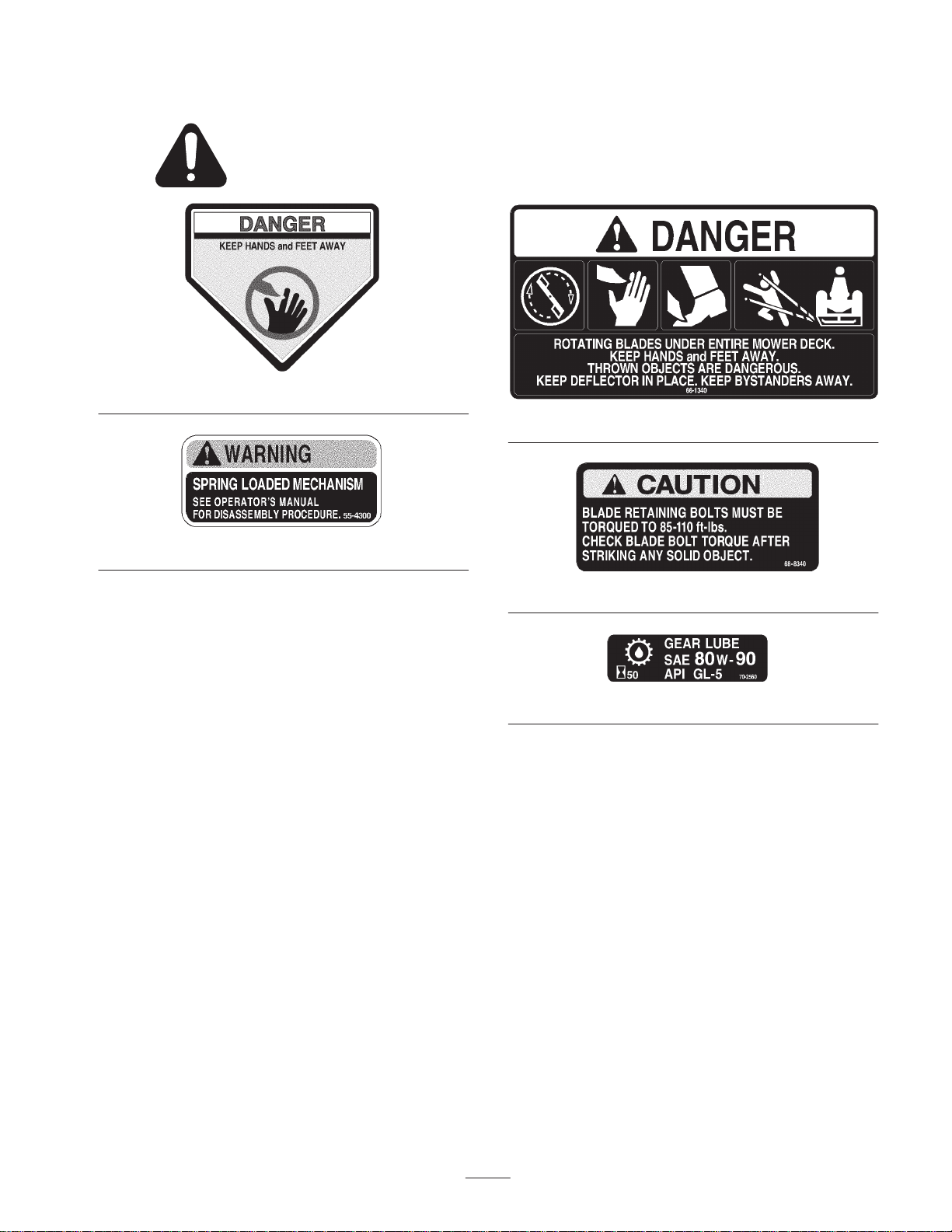
Safety and Instruction Decals
Safety decals and instructions are easily visible to the operator and are located near any area
of potential danger. Replace any decal that is damaged or lost.
43-8480
55-4300
66-1340
68-8340
70-2560
5
Page 6
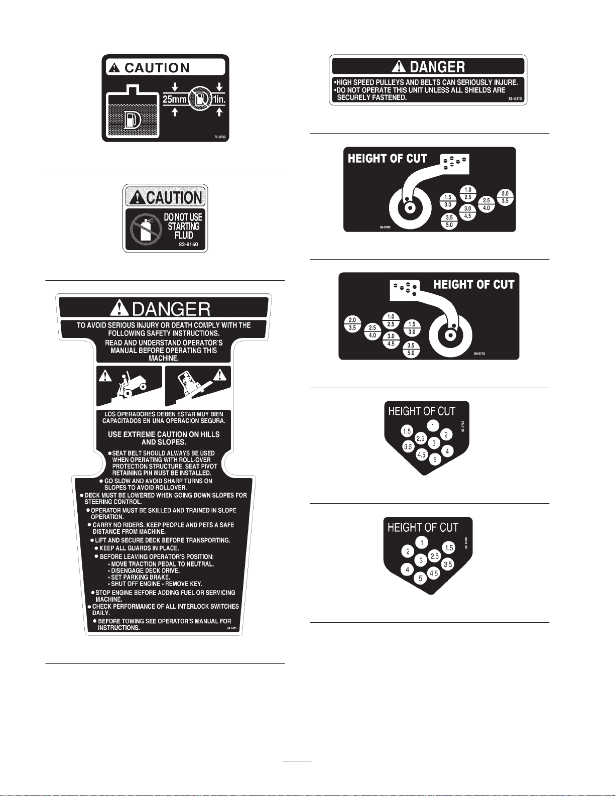
76-8780
83-9150
85-6410
86-0700
86-0710
84-1470
86-0720
86-0730
6
Page 7
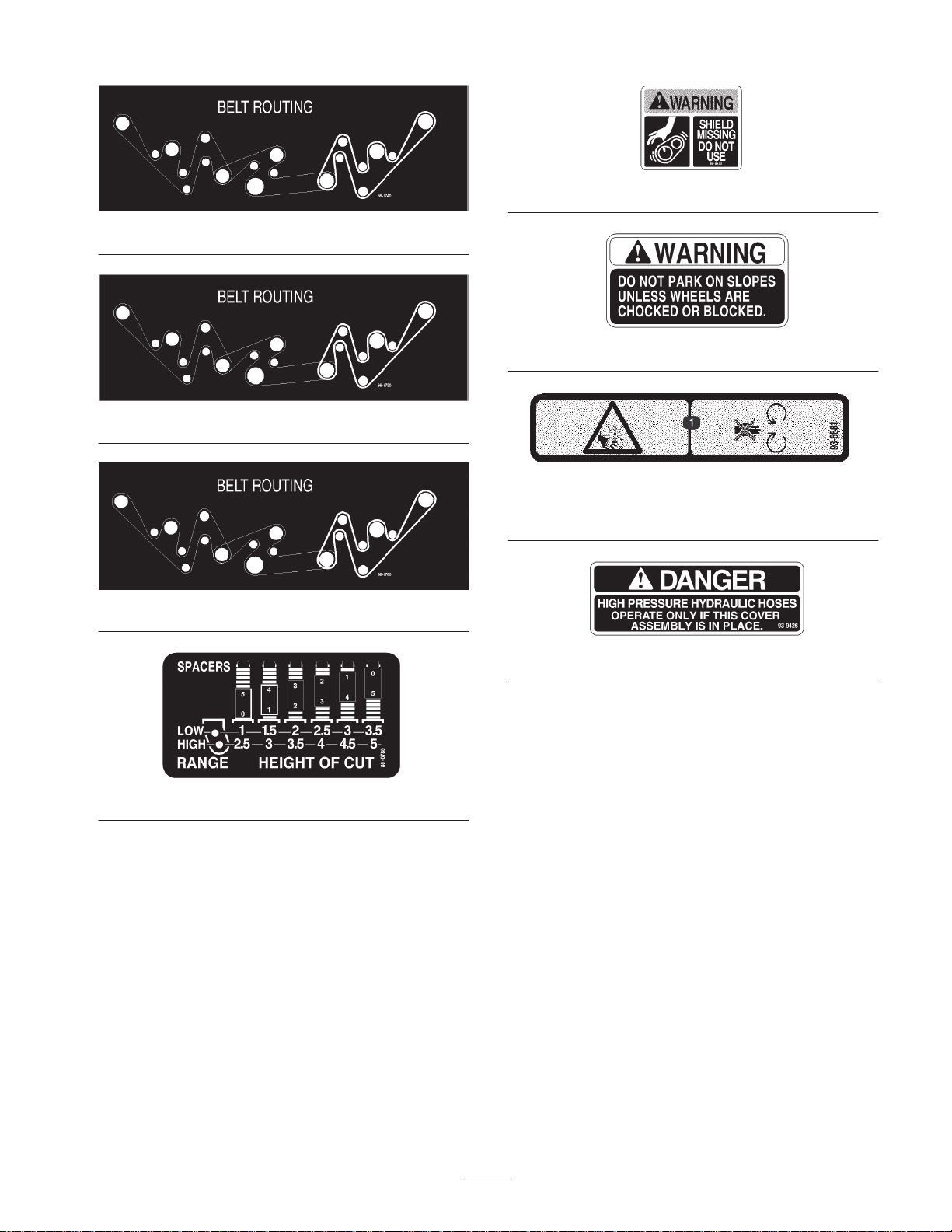
86-0740
86-0750
86-0760
88-8950
92-1370
93-6681
1. Cutting/dismemberment hazard, fan—stay away from moving
parts.
86-0780
93-9426
7
Page 8
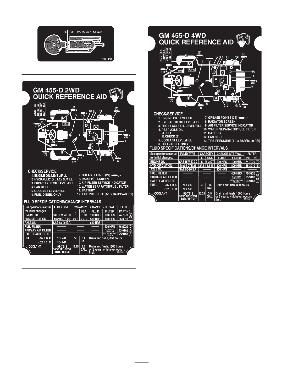
106-1005
93-7243
93-7242
8
Page 9

Specifications
Traction Unit
Peugeot, four-cycle, four cylinder, 1.9 liter (1900 cc) displacement, liquid cooled
Engine
diesel engine; 23.5:1 compression ratio; Low idle—1600 RPM, high
idle—3000 RPM
Cooling System
Fuel System Capacity is 12 gallons (45.4 l) of #1 or #2 diesel fuel.
Hydraulic System Reservoir capacity is 6.5 gallons (24.6 l); replaceable spin-on filter element
Traction System
Front Axle
Rear Axles
Tires/Wheels
Seat Adjustable fore and aft travel and weight
Diagnostic System
Capacity is 3.5 gallons (13.2 l) of 50/50 mixture of Peugeot recommended
anti-freeze (Part No. 93-7213)
Ground speed: Low Range; 0–6.5 MPH (0–10.5 km/h) forward and 0–3
(0–4.8 km/h) reverse; High Range: 0–13 MPH (0–20.9 km/h) forward and 0–5 MPH
(0–8 km/h) reverse
Two speed axle is designed to withstand heavy duty slope operation and side
loading. Separate mowing and transport selections for faster and more efficient
machine operation. Neutral position allows easy towing.
Two Wheel Drive: The large diameter wheel spindles are designed for durability
and long wear, yet provide superior stability and maneuverability.
Four Wheel Drive: Heavy duty, agricultural type. Hydraulic drive with “on demand”
bidirectional clutch and balanced weight distribution provides superior traction on
hillsides.
High floatation turf tread tires on de-mountable rims. Front tires: (2) 26 x 12.0–12,
8 ply. Rear tires: (2) 20 x 10.0–10, 6 ply. Tire pressure 20 psi (138 kPa).
Test ports for forward and reverse traction (2-wheel drive), front and rear axle
motors (4-wheel drive), lift and counterbalance circuit, steering circuit, and charge
circuit.
Steering System Automotive type, full power
Totally enclosed, non asbestos, dry multi-disc 5-5/8 in. individual wheel and parking
Brakes
Electrical System
Interlock System
Warning Lights
Indicators Engine coolant temperature gauge, fuel gauge, hour meter
brakes on front traction wheels; brakes controlled by individual pedals operated by
the left foot; dynamic braking through closed-loop hydrostatic drive.
12 volt battery with 650 cold cranking Amps @ 0°F, 55 amp alternator, ammeter,
starter, key switch, and automatic temperature controlled glow plug controller;
separately fused, run, deck and instrument/accessory circuits
Designed to stop engine if operator gets off seat while cutting deck drive switch is
engaged or traction pedal is forward or reverse. Prevents engine from starting
unless traction pedal is in neutral and cutting deck is disengaged. Prevents cutting
deck from operating unless axle shift is in LO range. Prevents traction unit from
moving if parking brake is engaged.
Glow plug indicator, engine oil pressure warning, engine coolant temperature
warning, charge indicator, water in fuel, low water indicator
9
Page 10

Cutting Unit
Type
Mowing Rate Mows up to 8 acres/hr (32,375 m2) at 6.5 MPH (10.5 km/h)
Trimability Trims on both sides
Height-of-Cut Adjustable from 1 to 5 in. (2.5 to 12.7 cm) in 1/2 in. (1.3 cm) increments
Construction
Cutter Drive
126 in. (320 cm) width of cut, seven blade, front mounted rotary; 54 in. (137 cm)
width of cut, three blade center section; two 36 in. (91 cm) width of cut wings, 90 in.
(229 cm) width of cut with one wing up; rear discharge with even dispersion over
the entire width of cut
Housings are 12 gauge high strength steel, 5.5 in. (14 cm) deep, welded
construction and reinforced with 10 gauge channel. Covers are impact resistant,
molded plastic.
PTO driven gear box with 1:1 spiral bevel gears. Triple 3V section belt to center
deck spindles, “B” section belt to each wing deck with patented belt routing.
1-1/4 inch diameter, spindle shafts mounted on two greaseable, tapered roller
bearings. A positive splined connection attaches pulleys to spindle shafts for high
torque capacity.
Blades
Belt Idlers Self-tensioning permanently lubricated idlers
Wing Decks
Suspension/Castor
Wheels
Seven 19 in. (48 cm) long, 1/4 in. (0.6 cm) thick, and 2-1/2 (6.4 cm) wide, heat
treated steel blades
Wings can be hydraulically raised from the operator’s seat for transport or cutting
with either wing and center deck or center deck only. Wings cut from level to 15° up
and down. Further lift disengages the blade and applies a blade brake.
Four front and two rear pneumatic castor tires with ball bearings. Center deck tires:
10.25 x 3.25 in. Wing deck tires: 8 x 3.25 in. Anti-scalp cup located on each blade.
Three anti-scalp rollers on center deck. Deck is hydraulically counterbalanced.
Measurements (approx.)
Overall length
(with deck installed)
Overall width
Transport
Mowing
Height
with ROPS installed
Wheel Tread
Front
Rear
Wheel base 52 in. (132 cm)
Dry weight
2-wheel drive
4-wheel drive
134 in. (34 m)
75 in. (1.9 m)
127 in. (3.23 m)
58 in. (1.5 m)
82 in. (2.1 m)
51 in. (130 cm)
41 in. (104 cm)
3800 lb. (1724 kg)
3900 lb. (1769 kg)
Optional Equipment
Broom Kit*
Snowthrower*
Roll Over Protection Kit*
(Standard on Model 30455)
Four Post Canopy Kit*
Spark Arrestor Muffler Part No. 94-5637
Segmented Wheel Kit Part No. 76-1880
Brake Light Kit Part No. 92-7763
Gear Box Pulley
(Tip Speed 14,500)
Windshield Kit*
Cruise Control Kit Model No. 30485
Road Light Kit Model No. 30471
Mulcher Kit Model NO. 30475
Cab*
Additional Weights*
Low Seat Option*
* Contact your local Toro distributor
Part No. 86-3100
Specifications and design subject to change without notice.
10
Page 11
Before Operating
Note: Determine the left and right sides of the machine from the normal operating position.
Description Qty. Use
Ignition key
Parts catalog
Commercial product setup card
Operator’s Manual
Registration card 1 Fill out and return to Toro.
Caution
Before servicing or making adjustments to the
machine, stop engine and remove key from the
switch.
Checking the Engine Oil
Crankcase capacity is 5.3 U.S. quarts (5.1 l) with filter.
1. Park machine on a level surface. Release hood latch and
open hood.
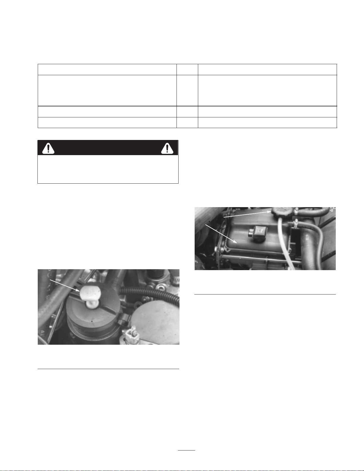
2. Remove dipstick from tube cap (Fig. 1), wipe clean and
reinstall dipstick into tube cap. Pull it out again and
check oil level on dipstick: Oil level must always be in
notch area on dipstick.
1
1
1
2 Read before operating the machine.
Checking the Cooling System
Capacity of system is 3.5 gallons (13.3 l)
1. Park machine on a level surface. Release hood latch and
open hood.
2. Check coolant level. Coolant level should be up to or
above mounting tabs on degasser tank, when engine
is cold (Fig. 2).
2
1
1
Figure 1
1. Dipstick/tube cap
3. If oil level is low, remove tube cap and add API
15W–40 CF, CF–4, or CG–4 oil until level reaches top
of notch on dipstick. DO NOT OVERFILL.
4. Install oil tube cap.
5. Close hood and secure latch.
Figure 2
1. Degasser tank 2. Degasser tank cap
3. If coolant is low, remove degasser tank cap (Fig. 2) and
add a 50/50 mixture of water and Peugeot
recommended anti-freeze (Toro Part No. 93-7213). Do
not use water only or alcohol/methanol base
coolants.
4. Install degasser tank cap.
5. Close hood and secure latch.
Filling the Fuel Tank
1. Park machine on a level surface. Release hood latch and
open hood.
2. Remove fuel tank cap (Fig. 3).
11
Page 12
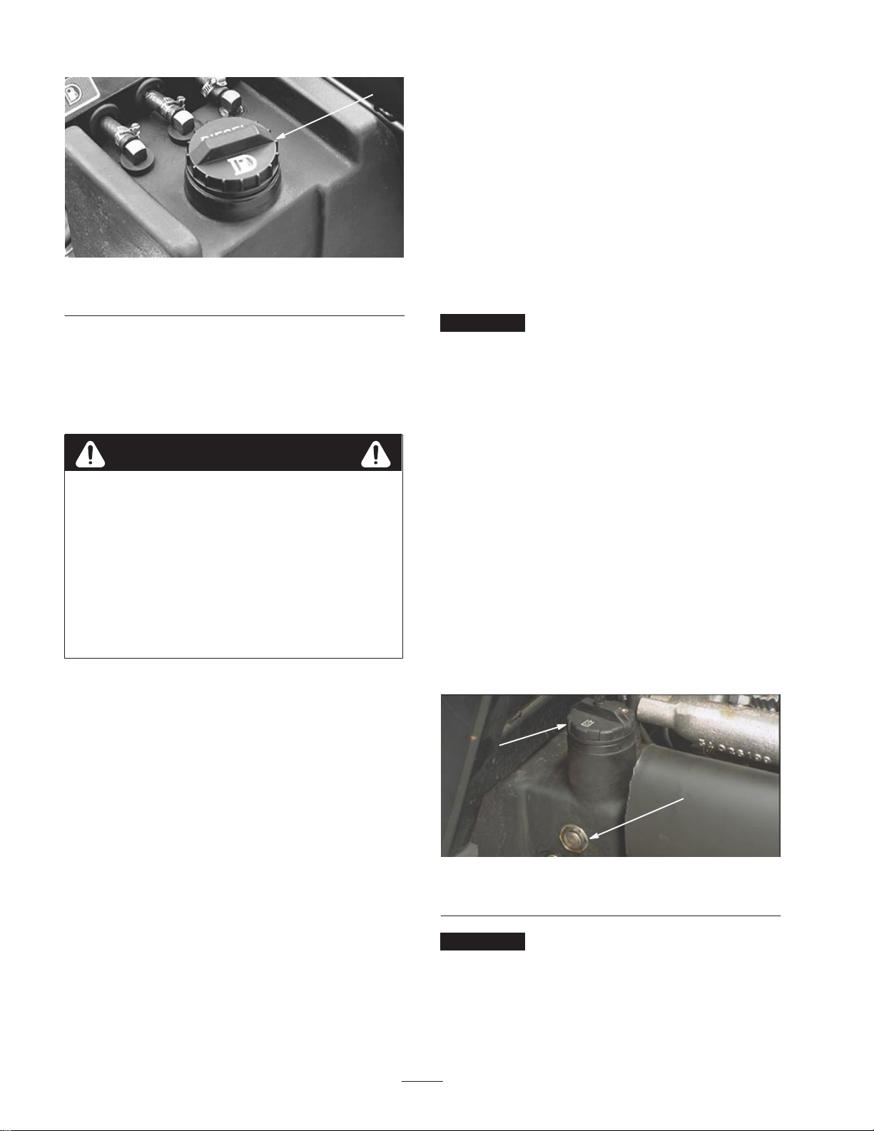
1
Figure 3
1. Fuel tank cap
3. Fill tank to no more than one inch (25 mm) below
bottom of filler neck with No. 2 diesel fuel. Do not
overfill. Then install cap.
Note: For temperatures below 32°F., No. 1 diesel fuel or a
blend should be used.
Danger
Because diesel fuel is highly flammable, use
caution when storing or handling it. Do not
smoke while filling the fuel tank. Do not fill
fuel tank while engine is running, hot, or
when machine is in an enclosed area. Always
fill fuel tank outside and wipe up any spilled
diesel fuel before starting the engine. Store
fuel in a clean, safety–approved container
and keep cap in place. Use diesel fuel for the
engine only; not for any other purpose.
4. Close hood and secure latch.
Multi-grade Hydraulic Fluid – ISO VG 46
Normal Climate: 0 (–18C) to 110F (43C)
Mobil DTE 15M
Amoco Rykon Premium ISO 46
Chevron Rykon Premium Oil ISO 46
Conoco Hydroclear AW MV46
Exxon Univis N46
Pennzoil AWX MV46
Shell Tellus T 46
Texaco Rando HDZ 46
Important The ISO VG 46 Multi-grade fluid has been
found to offer optimal performance in a wide range of
temperature conditions. For operation in consistently high
ambient temperatures, 65 F (18 C) to 120 F (49 C), ISO
VG 68 hydraulic fluid may offer improved performance.
Note: Many hydraulic fluids are almost colorless, making it
difficult to spot leaks. A red dye additive for the hydraulic
system oil is available in 2/3 oz. (20 ml) bottles. One bottle
is sufficient for 4–6 gal (15–22 1) of hydraulic oil. Order
part no. 44–2500 from your authorized Toro distributor.
Not recommended for biodegradable fluid (use food
coloring).
1. Park machine on a level surface and stop engine. Make
sure machine has been operated so oil is warm. Release
hood latch and open hood. Check level of oil by
viewing sight gauge (Fig. 4). If oil is visible in gauge,
oil level is sufficient.
2. If oil level is not visible in gauge, remove cap from
hydraulic oil reservoir (Fig. 4) and slowly add high
quality hydraulic fluid until level reaches middle
(maximum) of sight gauge. Do not overfill.
Checking the Hydraulic Circuit
Oil
The machine’s reservoir is filled at the factory with
approximately 6.5 gallons (24.6 l) of high quality hydraulic
fluid. Check the level of hydraulic fluid before the
engine is first started and daily thereafter. Appropriate
hydraulic oils are listed below.
The following list is not assumed to be all-inclusive.
Hydraulic fluids produced by other manufacturers may be
used if they can cross reference to find an equivalent to the
products listed. Toro will not assume responsibility for
damage caused by improper substitutions, so use only
products from reputable manufacturers who will stand
behind their recommendation.
2
1
Figure 4
1. Sight gauge 2. Hydraulic reservoir cap
Important To prevent system contamination, clean top
of hydraulic oil containers before puncturing. Assure pour
spout and funnel are clean.
12
Page 13
3. Install reservoir cap, close hood, and secure latch.
Checking the Front Axle Oil
Level
The front axle is shipped from the factory filled with SAE
80–90 wt. gear lube. However, check level before engine is
first started and every 50 hours thereafter. Capacity is
128 oz. Check daily for signs of oil loss.
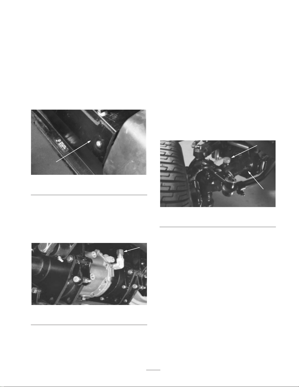
1. Park machine on a level surface.
2. Remove access panel (Fig. 5), in front of seat, to expose
front axle/dipstick.
1
4. Screw dipstick filler cap finger–tight onto filler neck. It
is not necessary to tighten cap with a wrench.
Checking the Rear Axle
Lubricant (Model 30455 Only)
The rear axle is shipped from the factory filled with SAE
80–90 wt. gear lube. However, check level before engine is
first started and every 50 hours thereafter. Capacity is
80 oz. Check daily for signs of oil loss.
1. Position the machine on a level surface.
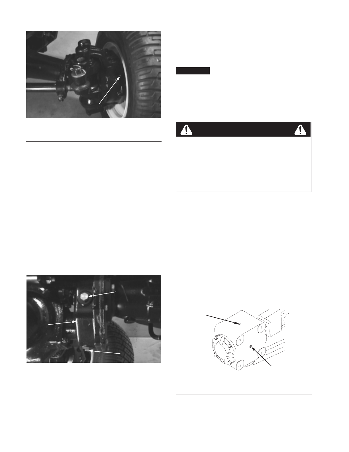
2. Clean area around the 3 check plugs, one on each end
and one in the center (Fig. 7 and 8).
3. Remove the check plugs and make sure lubricant is up
to bottom of hole. If level is low, add enough lubricant
to bring the level up to the bottom of the check plug
holes.
1
Figure 5
1. Access panel
3. Unscrew dipstick cap (Fig. 6) from the filler neck and
wipe it with a clean rag. Screw dipstick cap finger tight
onto filler neck. Unscrew the dipstick and check level
of lubricant. If level is not within 1/2 inch (13 mm)
from the groove in the dipstick, add enough to raise
level to groove mark. Do not overfill by more than
1/2 inch (13 mm) above groove.
Figure 6
1. Dipstick cap
2
Figure 7
1. Vent/fill plug 2. Check plug (3)
1
13
Page 14
Checking the Tire Pressure
The tires are over-inflated for shipping. Therefore, release
some of the air to reduce the pressure. Correct air pressure
in the front and rear tires is 20 psi (138 kPa).
Important Maintain even pressure in all tires to assure
a good quality-of-cut and proper machine performance. Do
not under-inflate.
1
Figure 8
1. Check/fill plug
Checking the Bidirectional
Clutch Lubricant (Model 30455
Only)
The Bidirectional Clutch is shipped from the factory filled
with Mobil DTE 15 M anti-wear hydraulic fluid. However,
check level before engine is first started and every 50 hours
thereafter. Capacity is 8 oz. Check daily for signs of oil
loss.
1. Position the machine on a level surface.
2. Remove check/fill plug from clutch housing (Fig. 9)
and make sure lubricant is up to bottom of hole. If level
is low, add enough lubricant to bring the level up to the
bottom of the check/fill plug hole.
Note: Do not use gear lube in clutch housing.
2
Checking the Torque of the
Wheel Nuts or Bolts
Warning
Torque front wheel nuts to 4555 ft-lb and
rear wheel nuts or bolts to 85100 ft-lb after
14 hours of operation and again after 10
hours of operation and every 200 hours
thereafter. Failure to maintain proper torque
could result in failure or loss of wheel and
may result in personal injury.
Checking the Lubricant in the
Gear Box
The gear box is designed to operate on SAE 80–90 wt. gear
lube. Although the gear box is shipped with lubricant from
the factory, initially, check the level before operating the
cutting unit and every 50 hours thereafter. Check daily for
signs of oil loss.
1. Position the machine and cutting unit on a level surface.
2. Remove check plug from side of gear box (Fig. 10) and
make sure lubricant is up to bottom of hole. If level of
lubricant is low, remove fill plug on top of gear case
(Fig. 10) and add enough lubricant to bring it up to
bottom of hole in side.
1
1. Clutch housing
2. Check/fill plug
Figure 9
3. Drain plug
1
3
2
Figure 10
1. Filler plug 2. Check plug
14
Page 15
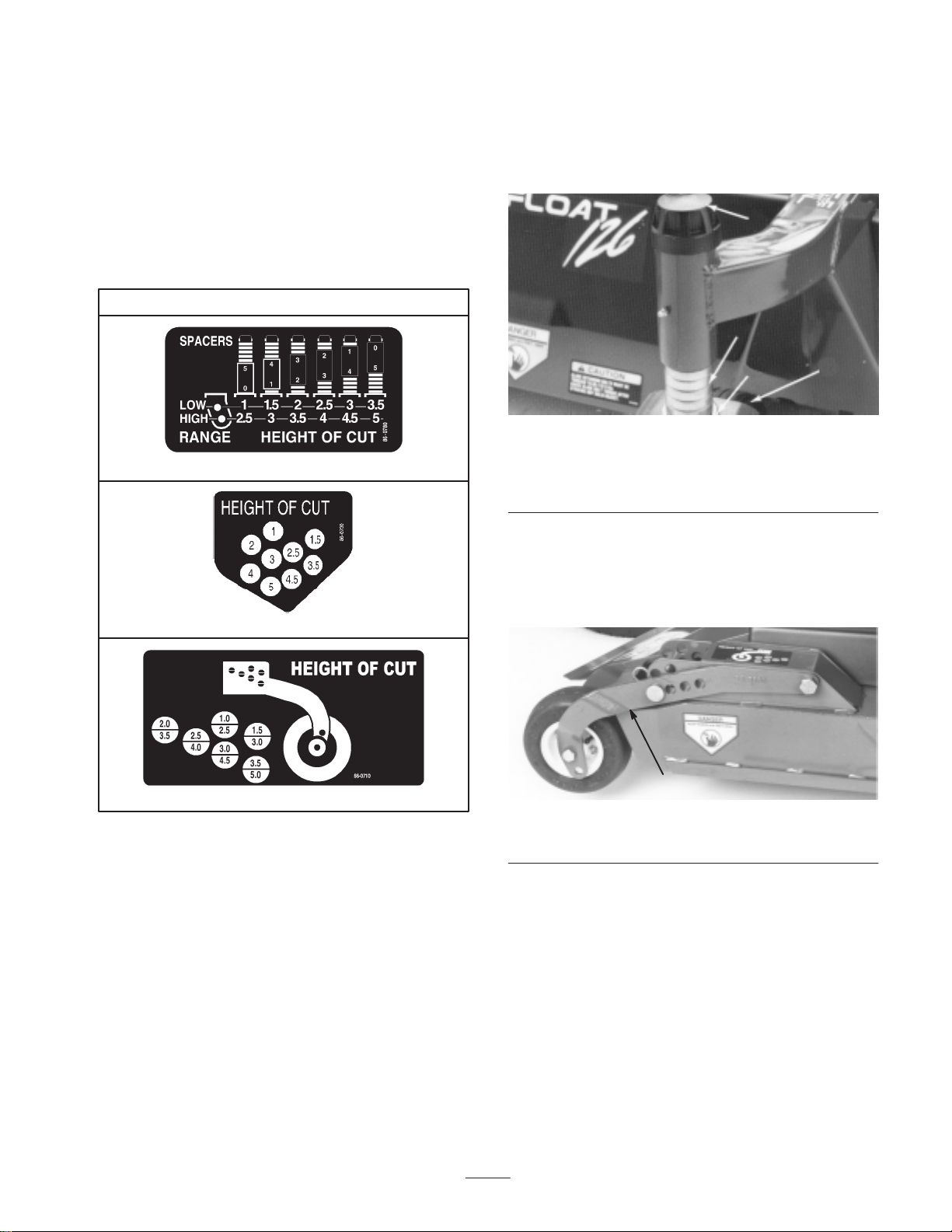
Adjusting the Height-of-Cut
The height-of-cut is adjustable from 1 to 5 inches (2.5 to
12.7 cm) in 1/2 inch (13 mm) increments. Positioning the
castor wheel axles in the top holes of the castor forks or
pivots (see chart below) allows low range height-of-cut
settings from 1 to 3-1/2 in. (2.5 to 8.9 cm); positioning the
castor wheel axles in the lower holes of the front castor
forks or rear castor pivots (See chart below) allows high
range height-of-cut settings from 2-1/2 to 5 in. (6.4 to
12.7 cm).
Height-of-Cut Chart
2. Push castor spindle through front castor arm, install
remaining spacers onto spindle, and install HOC cap to
secure assembly (Fig. 11).
Note: On Center deck only, make sure washer remains on
bottom of spindle shaft.
2
3
Front Castor Wheels
Rear Deck Straps
Rear Castor Wheels
1. Start the engine and raise the cutting unit so
height-of-cut can be changed. Stop engine after cutting
unit is raised.
2. Position all castor wheel axles in the same holes in the
castor forks or pivots.
1. Front castor wheel
2. HOC cap
3. Spacers
4
Figure 11
4. Washer (center deck
only)
1
Rear Castor Wheels
1. Remove hairpin cotter and H.O.C. pin securing rear
castor pivot arm to deck bracket (Fig. 12).
1
Figure 12
1. Rear castor pivot
2. Align the pivot arm holes with selected height-of-cut
bracket holes in the deck frame, install H.O.C. pin and
secure with hairpin cotter.
Front Castor Wheels
1. Remove HOC cap from spindle shaft and slide spindle
out of front castor arm (Fig. 11). Slide spacers onto
spindle shaft to get desired height-of-cut.
Rear Deck Straps
1. Lower center and wing cutting units to the ground; then
raise center cutting unit slightly, until rear deck straps
hang freely on wear block of lift arm brackets (Fig. 13).
Stop engine after cutting unit is raised.
15
Page 16
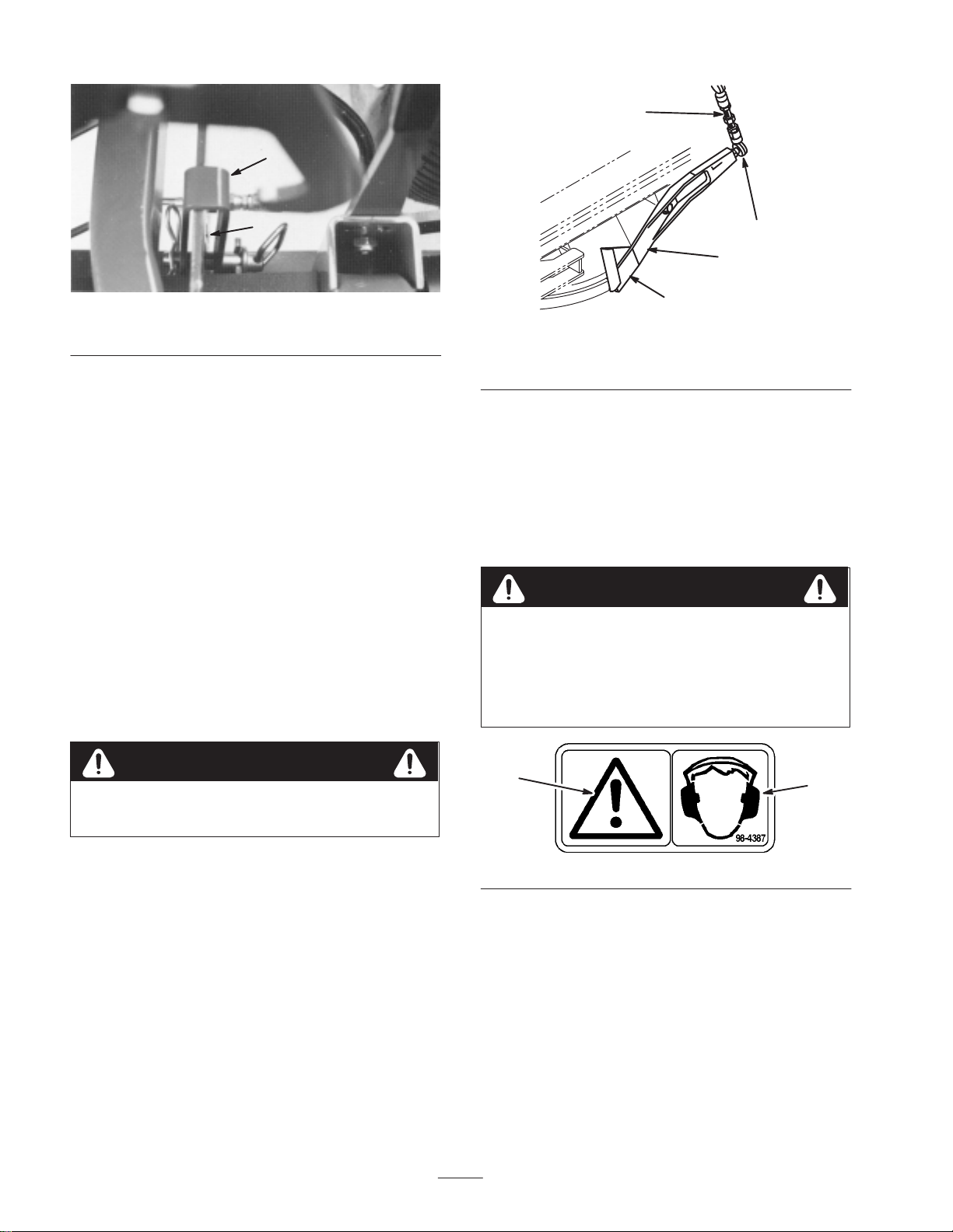
4
1
2
Figure 13
1. Rear deck straps 2. Lift arm brackets
2. Remove hairpin cotter and H.O.C. pin securing rear
deck strap to H.O.C. bracket on deck.
3. Slide deck strap forward or backward until holes in
strap are aligned with selected height-of-cut bracket
holes in the deck frame, install H.O.C. pin and secure
with hairpin cotter.
Safety Doors
On each side of the center deck is a safety door that opens
and closes as the wing decks are lowered and raised
(Fig. 14). The doors open to provide overlap of the cutting
blades when the wing units are down. The doors close to
provide safety and protection when the wing units are
raised. Check to make sure the forward, lower edge of door
is even or 1/4 in. (6 mm) higher then lower edge of door
guide when wing decks are in the fully raised, transport
position. If an adjustment to the door is required, refer to
Adjusting the Safety Door, page 41.
3
1
2
Figure 14
1. Safety door
2. Door guide
3. Ball joint
4. Threaded rod
Operation
Note: Determine the left and right sides of the machine
from the normal operating position.
The use of protective equipment, such as but not limited to, for
eyes, ears, feet, and head is recommended.
Caution
This machine produces sound levels in excess of
85 dBA at the operator’s ear and can cause
hearing loss through extended periods of exposure.
Wear hearing protection when operating this
machine.
Caution
Check the operation of the safety doors daily and
each time the deck is cleaned. Repair as needed.
1
1. Caution 2. Wear hearing protection
16
2
Page 17

Controls
Cutting Unit Engagement Switch
The cutting unit engagement switch (Fig. 15) is used to
start and stop cutting unit operation. Lift switch and move
forward to actuate cutting unit. Center deck will engage
first followed by wing decks engaging approximately one
second later.
Key Switch
The key switch (Fig. 15) has three positions: OFF, ON and
START. Rotate key to START and release key when engine
begins running. To stop engine, rotate key to OFF.
Throttle Control
Move the throttle control (Fig. 15) forward to increase
engine speed, backward to decrease speed.
4
1
3
2
5
1. Cutting unit engagement
switch
2. Glow plug indicator
3. Charge indicator
4. Key switch
5. Throttle control
6. Cutting unit lift controls
7. Coolant temperature
gauge
Figure 15
8. Fuel gauge
9. Low water indicator
10. Engine oil pressure
11. Engine coolant
12. Water in fuel warning light
10
6
11
7
8
12
warning light
temperature warning light
Cutting Unit Lift Controls
The two outside levers (Fig. 15) raise and lower the wing
cutting units. The center lever raises and lowers the whole
cutting unit. Engine must be running to lower cutting unit.
When wing cutting units are raised higher than15 , blades
automatically disengage. To lower cutting unit just touch
levers momentarily.
9
Coolant Temperature Gauge
The coolant temperature gauge (Fig. 15) shows temperature
of engine coolant.
Fuel Gauge
The fuel gauge (Fig. 15) shows amount of fuel in tank.
Low Water Indicator
The low water indicator (Fig. 15) indicates low water level
in cooling system.
Engine Oil Pressure Warning Light
Glow Plug Indicator
The glow plug indicator (Fig. 15) automatically actuates
proper glow period when ignition key is turned to ON
position. Illuminates when glow plugs are actuated. When
glow plugs are heated sufficiently, light goes off indicating
engine is ready to start.
Charge Indicator
The charge indicator (Fig. 15) illuminates when system
charging circuit malfunctions.
The engine oil pressure warning light (Fig. 15) indicates
dangerously low engine oil pressure.
Engine Coolant Temperature Warning
Light
The red light (Fig. 15) illuminates and the engine stops
when temperature of coolant exceeds 230°F.
Water in Fuel Indicator
The water in fuel indicator (Fig. 15) indicates when there is
water in fuel.
17
Page 18

Seat
Axle Shift Lever
Seat adjusting lever on left side of seat (Fig. 16) allows
4 inch (10.2 cm) fore and aft adjustment. Seat adjusting
knob on front of seat, adjusts seat for operator’s weight.
2
1
Figure 16
1. Seat adjusting lever 2. Seat adjusting knob
Traction Pedal
The traction pedal (Fig. 17) controls forward and reverse
operation. Depress top of pedal to move forward and
bottom to move backward. Ground speed depends on how
far pedal is depressed. For no load, maximum ground
speed, fully depress pedal while throttle is in FAST. For
maximum power under load or when going uphill, keep
engine rpm high by having throttle in FAST and traction
pedal partially engaged. If engine rpm begins to decrease
due to load, gradually reduce traction pedal pressure until
engine speed is increased.
The axle shift lever ,located on right side of console
(Fig. 17), selects front drive mode. Pull out lockout knob,
move lever rearward for mowing operation and forward for
transport operation, then release knob to lock selection.
Lever must be in LO position to mow. Middle position (N)
is for towing.
Important On model 30455, lever must be in LO
position to operate in 4-wheel drive.
Caution
The machine must be on a flat surface with the
brakes engaged when shifting the axle from the HI
to LO position.
Brake Pedals
Two foot pedals at the lower left (Fig. 18) operate
individual wheel brakes for turning assistance, braking,
parking and to aid in obtaining better sidehill traction.
Locking pin is for parking.
3
2
2
3
1
Figure 17
1. Traction pedal
2. Axle shift lever
3. Lockout knob
To stop, reduce foot pressure on traction pedal and allow it
to return to center position. On extreme downhill slopes,
apply pressure to REVERSE side of pedal, or operate with
heel on REVERSE and toe on FORWARD portion of pedal.
1. Brake pedals
2. Parking brake latch
1
Figure 18
3. Steering wheel tilt lever
18
Page 19

Parking Brake Latch
A knob on the left side of console (Fig. 18) actuates
parking brake lock. To engage parking brake, connect
pedals with locking pin, push down on both pedals and pull
parking brake latch out. To release parking brake, depress
both pedals until parking brake latch retracts.
Steering Wheel Tilt Lever
Lever on left side of console (Fig. 18) allows steering
wheel to be adjusted for operator comfort.
Transport Latches
Four latches (Fig. 19) secure cutting unit and wings in
upright position for transport operation.
1
Starting and Stopping
1. Sit on the seat, keep foot off traction pedal. Ensure that
the parking brake is engaged, traction pedal is in
NEUTRAL, and cutting unit engagement switch is in
the DISENGAGED position.
2. Turn ignition switch to ON position. When glow plug
indicator light goes off, engine is ready to START.
3. Turn ignition key to START. Release key when engine
starts.
4. To stop, disengage and move all controls to NEUTRAL
and set parking brake. Turn key to OFF and remove it
from switch. Raise and latch all cutting units in
transport position.
Priming the Fuel System
Important The fuel system may need to be primed
when a new engine is started for the first time, if it runs out
of fuel or if maintenance is performed on the fuel system.
1. Unlatch and raise hood.
2. Insert a 3/16 in. hose over bleed screw and run other
end into a container to catch fuel.
3. Loosen fuel filter/water separator bleed screw (Fig. 20)
a few turns. Pump priming plunger until a steady stream
of fuel comes out of hole in bleed screw. When fuel
stops foaming, tighten the bleed screw during the
downstroke of the priming plunger. Wipe up any spilled
fuel.
Figure 19
1. Transport latch
Hour Meter
The hour meter (under the hood) shows total hours that
machine has been operated.
Horn
The horn is in center of steering wheel. Operates only when
key switch is in ON.
Note: Priming fuel filter without opening bleed screw may
damage priming plunger.
4. Pump priming plunger until resistance is felt. Try to
start engine. If engine does not start repeat step 3.
1
2
Figure 20
1. Primer plunger 2. Bleed screw
19
Page 20

Note: Note: It may be necessary to bleed the air out of the
fuel line between the fuel filter / water separator and the
injection pump. To do this, loosen the fitting on the
injection pump (Fig. 21) and repeat bleeding procedure.
Figure 21
1. Injection pump fitting
switch is operating correctly; thus, proceed to step 5. If
engine does not stop, there is a malfunction in the
interlock system.
5. Engage parking brake and depress the traction pedal
while engine is running and the cutting unit engagement
1
switch is DISENGAGED. The engine should stop
within 2 seconds. If engine stops, the switch is
operating correctly; thus, continue operation. If engine
does not stop, there is a malfunction in the interlock
system.
6. Rise from the seat and depress the traction pedal while
engine is running and the cutting unit engagement
switch is DISENGAGED. The engine should stop
within 2 seconds. If engine stops, the switch is
operating correctly; thus, continue operation. If engine
does not stop, there is a malfunction in the interlock
system.
Operating Characteristics
Checking the Interlock System
The purpose of the interlock system is to prevent the engine
from cranking or starting unless the traction pedal is in
NEUTRAL and the cutting unit engagement switch is
DISENGAGED. In addition, the engine will stop when the
cutting unit engagement switch is engaged or traction pedal
is depressed with operator off the seat, or if the parking
brake is engaged.
Caution
If safety interlock switches are disconnected or
damaged, the machine could operate unexpectedly
causing personal injury.
• Do not tamper with the interlock switches.
• Check the operation of the interlock switches
daily and replace any damaged switches before
operating the machine.
• Replace switches every two years regardless of
whether they are operating properly or not.
1. In a wide open area free of debris and bystanders, lower
cutting unit to the ground. Stop engine.
Familiarization
Before mowing grass, practice operating machine in an
open area. Start and stop the engine. Operate in forward
and reverse. When you feel familiar with the machine,
practice operating around trees and obstacles. Also drive up
and down slopes at different speeds.
Warning
When operating 4-wheel drive machine, always use
the seat belt and ROPS together and have seat
pivot retaining pin installed.
Another characteristic to consider is the operation of the
brake pedals. The brakes can be used to assist in turning the
machine. However, use them carefully, especially on soft or
wet grass because the turf may be torn accidentally.
Another benefit of the brakes is to maintain traction. For
example: When operating on a sidehill, the uphill wheel
slips and loses traction. If this situation occurs, depress
uphill brake pedal gradually and intermittently until the
uphill wheel stops slipping, thus, increasing traction on the
downhill wheel.
2. Move cutting unit engagement switch to
DISENGAGED position and remove foot from traction
pedal so it is fully released.
3. Rotate the ignition key to START. Engine should start.
If engine starts, proceed to step 4. If engine does not
start, there may be a malfunction in the interlock
system.
4. Rise from the seat and engage the cutting unit
engagement switch while the engine is running. The
engine should stop within 2 seconds. If engine stops, the
Warning System
If a warning light comes on during operation, stop the
machine immediately and correct the problem before
continuing operation. Serious damage could occur if the
machine is operated with a malfunction.
Mowing
When you are at the area to be mowed, release cutting unit
transport latches.
20
Page 21

Move axle shift lever rearward to Mow position and
throttle to FAST so engine is running at maximum speed.
Lift engagement switch and move forward to engage
cutting units.
Curbside Mowing
To reduce the possibility of foreign debris escaping from
under the cutter deck while mowing at or near a road or
walkway curb, always keep the outside edge of the cutter
deck inside the curb. The cutter deck caster wheels should
not be guided along the top of the curb; this could cause the
cutter deck to hang over the edge of the curb. Never allow
the edge of the cutter deck to extend over the edge of the
curb while the blades are turning. Always stop mowing and
disengage the mower blades when encountering pedestrians
or other bystanders.
Operating Tips
Mow When Grass is Dry
Mow either in the late morning to avoid the dew, which
causes grass clumping or in late afternoon to avoid the
damage that can be caused by direct sunlight on the
sensitive, freshly mowed grass.
Select the Proper Height-of-Cut Setting to
Suit Conditions
Remove approximately one inch or no more than 1/3 of the
grass blade when cutting. In exceptionally lush and dense
grass you may have to raise your height–of–cut setting
another notch.
Note: Cutting deck is equipped with a breakaway system to
prevent wing decks from being damaged if a solid object is
struck. If a wing deck strikes a solid object and unlatches
from center cutting deck, raise and lower wing deck to reset
in operating position.
Warning
Cutting deck breakaway system is equipped with a
highly compressed spring. If spring removal or
repair is required, contact your local authorized
Toro Distributor for assistance.
Transport
When mowing is complete, disengage cutting unit and raise
it by pulling back on cutting unit lift control levers. Hold
levers back until cutting unit is fully raised. Never raise
cutting deck when engaged. Lock cutting unit in place
with transport latches. Move axle shift lever forward to HI
position. When driving from one area to another, always
shift axle to LO position before encountering a slope.
Never shift from HI to LO position while on a slope. Stop
machine on a flat surface, engage brakes and shift before
climbing the slope. Be careful when driving between
objects so you do not accidentally damage the machine or
cutting unit.
Use extra care when operating machine on slopes. Drive
slowly and avoid sharp turns on slopes to prevent roll
overs. The cutting unit must be lowered when going
downhill for steering control.
Mowing in Extreme Conditions
Air is required to cut and recut grass clippings in mower
housing, so do not set height-of-cut too low or totally
surround housing by uncut grass. Always try to have one
side of the mower housing free from uncut grass, allowing
air to be drawn into housing. When making an initial cut
thru center of uncut area, operate machine slower and back
up if mower starts to clog.
Clippings Discharge
Although the deck has rear discharge, some clippings are
discharged toward the left side. To avoid discharging
undesirable clippings onto pathways, roads, or other
non–turf surfaces, mow with the right side of the deck next
to the pathway, road, or other non-turf surface.
Mow at Proper Intervals
Under most normal conditions you’ll need to mow
approximately every 4–5 days. But remember, grass grows
at different rates at different times. This means that in order
to maintain the same height–of–cut, which is a good
practice, you’ll need to cut more frequently in early spring;
as the grass growth rate slows in mid summer, cut only
every 8–10 days. If you are unable to mow for an extended
period due to weather conditions or other reasons, mow
first with the height-of-cut at a high level; then mow again
2–3 days later with a lower height setting.
Always Mow with Sharp Blades
Pushing or Towing Traction Unit
Use only a rigid tow bar if it becomes necessary to tow
machine. Make sure axle shift lever is in NEUTRAL
position and only tow the machine forward. Use trailer for
normal transport. Move axle shift lever to LO position
before loading machine on a trailer.
A sharp blade cuts cleanly and without tearing or shredding
the grass blades like a dull blade. Tearing and shredding
causes the grass to turn brown at the edges which impairs
growth and increases susceptibility to diseases.
21
Page 22

After Operating
To ensure optimum performance, clean underside of mower
housings and under belt covers after each use. Use low psi
compressed air only. Do not use water. If residue is
allowed to buildup in mower housings, cutting performance
will decrease.
22
Page 23

Maintenance
Recommended Maintenance Schedule
Maintenance Service
Interval
After first 10 hours
After first 50 hours
Every 50 hours
Every 100 hours
Every 200 hours
Every 400 hours
Maintenance Procedure
• Inspect the PTO and cutting unit belts.
• Torque the wheel lug nuts.
• Inspect the engine fan belt.
• Change the engine oil and filter.
• Check the electric deck clutches adjustment.
• Check the electric PTO clutch adjustment.
• Check the engine RPM (at idle and full throttle).
• Change the hydraulic oil filter.
• Lubricate all grease fittings.
• Check the cutting unit gear box oil level.
• Check the rear axle oil level (4wd).
• Change the engine oil and filter.
• Check the battery level/cable connections.
• Inspect the cooling system hoses.
• Inspect the PTO and cutting unit belts.
• Check the electric deck clutches adjustment.
• Check the electric PTO clutch adjustment.
• Torque the wheel lug nuts.
• Service the air cleaner.
• Change the fuel filter.
• Check the front transaxle oil level.
• Inspect the fuel lines and connections.
• Check the engine RPM (at idle and full throttle).
• Change the rear axle oil (4wd).
1
• Inspect the engine fan belt.
• Inspect the engine timing belt.
• Drain and clean the fuel tank.
• Change the hydraulic oil
Every 800 hours
Every 1500 hours or
2 years, whichever
occurs first
1
If the indicator shows red
2
Replace the timing belt if worn, cracked, or oil soaked. A new timing belt should be installed any time the belt is removed or loosened.
Important Refer to your engine operator’s manual for additional maintenance procedures.
• Change the hydraulic oil filter.
• Change the front transaxle oil
• Pack the rear axle bearings (2wd).
• Change the bidirectional clutch fluid (4wd).
• Check the rear wheel toe-in.
• Replace moving hydraulic hoses.
• Replace safety switches.
• Flush the cooling system and replace fluid.
• Replace PTO belts and cutting deck belts.
2
23
Page 24

Daily Maintenance Checklist
Duplicate this page for routine use.
For the week of:
Maintenance Check Item
Check the safety interlock system.
Check the brake operation.
Check the engine oil level.
Check the fuel level.
Check the cooling system fluid level.
Drain the water/fuel separator.
Check the air filter restriction indicator.
Check the radiator and screen for
1
debris.
Check for unusual engine noises.
2
Check for unusual operating noises.
Check the hydraulic system oil level.
Check the hydraulic hoses for damage.
Check for fluid leaks.
Check the tire pressure.
Check instrument operation.
Mon. Tues. Wed. Thurs. Fri. Sat. Sun.
Check the cutting unit safety doors.
Check the height-of-cut adjustment.
Clean the deck belt area.
1
Check the condition of the blades.
Lubricate all grease fittings.
3
Touch up damaged paint.
1
Use only low pressure compressed air for debris removal. Do not use water.
2
Check the glow plug and injector nozzles if hard starting, excess smoke, or rough running is noted.
3
Immediately after every washing, regardless of the interval listed
Notation for Areas of Concern
Inspection performed by:
Item Date Information
1
2
3
4
5
6
7
24
Page 25

SERVICE INTERVAL CHARTS
4 Wheel Drive2 Wheel Drive
DTE 15M
DTE 15M
25
Page 26

Lubricating the Machine
The traction unit and cutting unit have grease fittings that
must be lubricated regularly with No. 2 General Purpose
Lithium Base Grease. If machine is operated under normal
conditions, lubricate all grease fittings after every 25 hours
of operation. Lubricate all grease fittings immediately after
every washing, regardless of interval listed.
The grease fittings that must be lubricated are: lift arm
pivot (2), lift cylinder (4), brake arm pivots (2) (Fig. 22);
brake pivot (1), brake pivots (2) (Fig. 23); traction pedal
pivot (1) (Fig. 24); engine to pump drive shaft (2) (Fig. 25
and 26); traction adjuster (1) (Fig. 27); P.T.O. Bearing
(Fig. 28).
2 wheel drive machines only—cylinder end (2), center
pivot (1), spindles (2), tie rod assembly (2) (Fig. 29).
4 wheel drive machines only—center pivot (1) (Fig. 30); tie
rod assembly (2), king pin bushings (2) The top fitting on
the king pin should only be lubricated annually
(2 pumps), cylinder ends (2) (Fig. 31).
Cutting deck (2 & 4 wheel drive machines)—blade spindles
(7), lift cylinder ball joints (4) and wing deck pivot pins (4)
(Fig. 32); castor fork shaft (4) (Fig. 33); PTO to gear box
drive shaft assembly (3) (Fig. 34); wing deck ball joints (4)
(Fig. 35), and lift arm ball joints (2) (Fig. 36).
Figure 23
1. Wipe grease fittings clean before lubricating.
2. Pump grease into fitting.
3. Wipe up excess grease.
Figure 22
Figure 24
Figure 25
26
Page 27

Important Failure to lubricate the hydro pump drive
fitting will result in a failure.
Figure 26
Figure 28
Figure 27
Figure 29
27
Page 28

Figure 30
1
Figure 32
Figure 33
1. Top fitting on king pin
Figure 31
28
Page 29

Figure 34
Figure 36
Figure 35
29
Page 30

Caution
Before servicing or making adjustments to the
machine, stop engine and remove key from the
switch.
Servicing the Air Cleaner
Checking the Air Cleaner
1. Check air cleaner body for damage which could
possibly cause an air leak. Replace a damaged air
cleaner body.
2. Service the air cleaner filters when ever air cleaner
indicator (Fig. 37) shows red or every 400 hours (more
frequently in extreme dusty or dirty conditions). Do not
over service air filter.
2. Gently slide primary filter (Fig. 39) out of air cleaner
body to reduce the amount of dust dislodged. Avoid
knocking filter against air cleaner body. Do not remove
safety filter.
1
Figure 39
1. Air cleaner primary filter
1
Figure 37
1. Air cleaner indicator
3. Be sure cover is sealing around air cleaner body.
Cleaning the Element
1. Release locking tab securing air cleaner cover to air
cleaner body. Separate cover from body (Fig. 38). Clean
inside of air cleaner cover.
1
3. Inspect primary filter and discard if damaged. Do not
wash or reuse a damaged filter.
Important Never attempt to clean a safety filter
(Located inside primary filter). Replace the safety filter
with a new one after every three primary filter services.
4. Use compressed air to clean the filter:
A. Blow compressed air from inside to the outside of
dry filter element. Do not exceed 100 psi (689 kPa)
to prevent damage to the element.
B. Keep air hose nozzle at least 2 in. (5 cm) from filter
and move nozzle up and down while rotating the
filter element. Inspect for holes and tears by looking
through the filter toward a bright light.
5. Inspect new filter for shipping damage. Check sealing
end of filter. Do not install a damaged filter.
6. Insert new filter properly into air cleaner body. Make
sure filter is sealed properly by applying pressure to
outer rim of filter when installing. Do not press on
flexible center of filter.
7. Reinstall cover and secure locking tab. Make sure cover
is positioned with TOP side up.
1. Dust cup
8. Reset indicator (Fig. 37) if showing red.
Figure 38
30
Page 31

Servicing the Engine Oil and
Servicing the Fuel System
Filter
Change oil and filter initially after the first 50 hours of
operation, thereafter change oil and filter every 100 hours.
1. Remove drain plug (Fig. 40) and let oil flow into drain
pan. When oil stops, install drain plug and new plug
seal.
1
Figure 40
1. Drain plug
Draining the Fuel Tank
Drain and clean fuel tank every 800 hours of operation or
yearly, whichever comes first. Also, drain and clean tank if
fuel system becomes contaminated or if machine is to be
stored for an extended period. Use clean fuel to flush out
the tank.
Danger
Because diesel fuel is highly flammable, use
caution when storing or handling it. Do not
smoke while filling the fuel tank. Do not fill
fuel tank while engine is running, hot, or
when machine is in an enclosed area. Always
fill fuel tank outside and wipe up any spilled
diesel fuel before starting the engine. Store
fuel in a clean, safety–approved container
and keep cap in place. Use diesel fuel for the
engine only; not for any other purpose.
Checking the Fuel Lines and Connections
Check lines and connections every 400 hours or yearly,
whichever comes first. Inspect for deterioration, damage, or
loose connections.
2. Remove oil filter (Fig. 41). Apply a light coat of clean
oil to the new filter seal before screwing it on. Do not
over-tighten.
1
Figure 41
1. Oil filter
3. Add API 15W-40 CF, CF-4, or CG-4 oil to crankcase.
Capacity is 5.3 quarts (5 l) with filter.
Draining the Fuel Filter/Water Separator
Drain water or other contaminants from fuel filter/water
separator daily.
1. Place a clean container under fuel filter (Fig. 42).
3
2
Figure 42
1. Fuel filter/water separator
2. Drain screw
2. Loosen drain thumb screw on side of fuel filter and
press primer plunger until only fuel is evident draining
into container.
3. Primer plunger
1
31
Page 32

3. Tighten drain screw.
Changing the Fuel Filter
Replace fuel filter if fuel flow becomes restricted, after
every 400 hours of operation or annually, whichever comes
first.
1. Unscrew bottom filter cap from filter assembly.
Remove cap, gaskets, o-ring and filter from assembly.
Note position of gaskets and o-ring when disassembling
from filter.
2. Install new filter, gaskets, o-ring with filter assembly
cap.
3. Prime fuel system; refer to Priming the Fuel System,
page 19.
Servicing the Engine Cooling
System
3. Unscrew knobs and pivot oil cooler rearward. Clean
both sides of oil cooler and radiator area thoroughly
with low pressure compressed air. Open hood and blow
debris out toward back of machine. Pivot oil cooler
back into position and tighten knobs.
Note: Upper portion of fan shroud may be easily unbolted
from machine to simplify cleaning.
4. Install rear screen and tighten knobs.
Important Do not use water to clean engine, as
damage may occur.
Maintaining the Cooling System
Capacity of the system is 3.5 gallons (13.3 l). Always
protect cooling system with a 50/50 solution of water and
Peugeot recommended anti-freeze. Do not use water only
in the cooling system.
After every 100 operating hours, tighten hose connections.
Replace any deteriorated hoses.
Removing Debris
Remove debris from rear screen, oil cooler and radiator
daily, clean more frequently in dirty conditions. Use low
pressure compressed air.
Important Never spray water onto a hot engine or onto
electrical connections as damage may occur.
1. Turn engine off, release hood latch and raise hood.
Clean engine area thoroughly of all debris. Close hood.
2. Unscrew knobs and remove rear screen (Fig. 43). Clean
screen thoroughly.
1
Figure 43
1. Rear screen
After every 2 years or 1500 hours, drain and flush the
cooling system. Add anti-freeze; refer to Checking the
Cooling System, page 11.
1
Figure 44
1. Oil cooler
Adjusting the Engine Fan Belt
Check condition and tension of fan belt (Fig. 45)
frequently. It is recommended that belt be inspected every
800 hours of operation.
1. Proper tension will allow 1/4 in. (6 mm) deflection on
the belt midway between the pulleys, when pressed
firmly with thumb.
32
Page 33

2. If deflection exceeds 1/4 in. (6 mm), loosen alternator
mounting bolts. Adjust alternator belt tension by
adjusting tension screw (Fig. 45). Check deflection of
belt again to assure tension is correct.
1
2
Figure 45
1. Fan belt 2. Adjusting screw
Checking the Engine Timing
Belt
Inspect engine timing belt every 800 hours of operation or
yearly.
Remove covers and check for worn, cracked, or oil soaked
belt.
1
Figure 46
1. Hydraulic reservoir drain
4. Install reservoir cap, lower hood, and latch. Start engine
and use all hydraulic controls to distribute hydraulic oil
throughout the system. Also check for leaks. Then stop
the engine.
5. With wing decks raised, center deck down and oil
warm, look into sight gauge (Fig. 47). If hydraulic oil is
not visible, add enough oil to raise level to middle
(maximum) of sight gauge. To prevent over filling, do
not fill if oil is cold. Do not overfill.
Note: A new belt should be installed any time belt is
removed or loosened.
Changing the Hydraulic Oil
Change hydraulic oil filter initially after the first 50 hours
of operation, thereafter change hydraulic oil and filter after
every 800 operating hours. If oil becomes contaminated,
contact your local Toro distributor because the system must
be flushed. Contaminated oil looks milky or black when
compared to clean oil.
1. Turn engine off, release hood latch, and raise hood.
2. Remove drain plug from rear of reservoir and hydraulic
line from front of reservoir (Fig. 46) and let hydraulic
oil flow into drain pan. Reinstall and tighten plug and
line when hydraulic oil stops draining.
3. Fill reservoir with approximately 6.5 gallons (24.6 l) of
hydraulic oil; refer to Checking the Hydraulic Circuit
Oil, page 12.
Important Use only hydraulic oils specified. Other
fluids could cause system damage.
1
Figure 47
1. Sight gauge
33
Page 34

Replacing the Hydraulic Filter
Initially, change filter after the first 50 operating hours,
thereafter, every 800 operating hours or annually,
whichever comes first.
Only the Toro replacement filter (Part No. 86-3010) can be
used in the hydraulic system.
Important Use of any other filter may void the
warranty on some components.
1. Turn engine off, release hood latch and raise hood.
2. Clean area around filter mounting area (Fig. 48). Place
drain pan under filter and remove filter.
Warning
Keep body and hands away from pin hole leaks or
nozzles that eject high pressure hydraulic fluid.
Use cardboard or paper to find hydraulic leaks.
Hydraulic fluid escaping under pressure can
penetrate skin and cause injury. Fluid accidentally
injected into the skin must be surgically removed
within a few hours by a doctor familiar with this
form of injury or gangrene may result.
Checking the Hydraulic System
Test Ports
The test ports are used to test the hydraulic circuits. Check
all pressures when engine is at full speed and hydraulic oil
is at normal operating temperature. Contact your local Toro
distributor for assistance.
Traction Forward and Reverse (Fig. 49) have a normal
relief setting of approximately 6000 psi.
Normal charge pressure is 100–140 psi (689–965 kPa).
1
Figure 48
1. Hydraulic filter
3. Lubricate new filter gasket and fill the filter with
hydraulic oil.
4. Ensure filter mounting area is clean. Screw filter on
until gasket contacts mounting plate. Then tighten filter
one half turn.
5. Start engine and let run for about two minutes to purge
air from the system. Stop the engine and check oil level.
Also check for any leaks.
Checking the Hydraulic Lines
and Hoses
Check hydraulic lines and hoses daily for leaks, kinked
lines, loose mounting supports, wear, loose fittings, weather
deterioration and chemical deterioration. Make all
necessary repairs before operating.
1
2
Figure 49
1. Traction forward circuit 2. Traction reverse circuit
Cutting unit Counterbalance normal setting is
approximately 600–650 psi (4137–4482 kPa) at high idle
and when oil is warm.
Lift circuit relief pressure is approximately 2600–2800 psi
(17,926–19,305 kPa) when oil is warm.
Steering Circuit has a normal relief setting of
approximately 1200 psi (8274 kPa) at high idle and warm
oil.
34
Page 35

Adjusting the Traction Drive for
Neutral
The machine must not creep when traction pedal is
released. If it does creep, an adjustment is required.
1. Park machine on a level surface, shut engine off and
move shift lever to “HI” position. Depress only the left
brake pedal and engage the parking brake.
2. Jack up right side of machine until front tire is off the
1
shop floor. Support machine with jack stands to prevent
it from falling accidentally.
Figure 50
1. Charge pressure
2
1
Figure 51
1. Counterbalance/lift circuit 2. Steering circuit
Wing deck cutting unit Counterbalance normal setting is
approximately 350–400 psi (2413–2758 kPa) at high idle
and when oil is warm (Fig. 52).
3. Under left side of machine, loosen locknut on traction
adjustment cam (Fig. 53).
1
2
Figure 53
1. Traction adjustment cam 2. Locknut
4. Start engine and rotate cam hex in either direction until
wheel ceases rotation.
Warning
Figure 52
1. Counterbalance (wing decks)
Engine must be running so final adjustment of the
traction adjustment cam can be performed. To
guard against possible personal injury, keep hands,
feet, face and other parts of the body away from
the muffler, other hot parts of the engine, and
other rotating parts.
5. Tighten locknut locking adjustment.
1
6. Stop the engine and release the right brake. Remove
jack stands and lower the machine to the shop floor.
Test drive the machine to make sure it does not creep.
35
Page 36

Changing the Front Axle
Lubricant
After every 800 hours of operation the oil in the front axle
must be changed.
1. Position machine on a level surface.
2. Clean area around the drain plug (Fig. 54).
1
1
Figure 55
1. Drain plugs (3)
Changing the Bidirectional
Clutch Lubricant
Figure 54
1. Front axle drain plug
3. Remove plug allowing oil to drain into drain pans.
4. After oil is drained, reinstall drain plug into axle.
5. Fill axle with lubricant; refer to Checking the Front
Axle Oil Level, page 13.
Changing the Rear Axle
Lubricant (Model 30455 Only)
After every 400 hours of operation the oil in the rear axle
must be changed.
1. Position machine on a level surface.
2. Clean area around the 3 drain plugs, one on each end
and one in the center (Fig. 55).
3. Remove plugs allowing oil to drain into drain pans.
4. After oil is drained, apply thread sealing compound
on drain plug threads and reinstall in axle.
5. Fill axle with lubricant; refer to Checking the Rear Axle
Lubricant, page 13.
(Model 30455 Only)
After every 800 hours of operation the oil in the clutch
housing must be changed.
1. Position the machine on a level surface.
2. Remove drain plug from clutch housing (Fig. 56)
allowing fluid to drain into drain pan.
2
1
3
Figure 56
1. Clutch housing
2. Check/fill plug
3. After fluid is drained, reinstall drain plug.
3. Drain plug
4. Remove check/fill plug and add 8 oz. of Mobil DTE
15 M anti-wear hydraulic fluid.
Note: Do not use gear lube in clutch housing.
5. Install check/fill plug.
36
Page 37

Adjusting Rear Wheel Toe-In
After every 800 operating hours or annually, check rear
wheel toe-in.
Measure center-to-center distance (at axle height) at front
and rear of steering tires. Front and rear measurements
must be within 1/8 in. (3 mm) of each other.
Adjusting 2-Wheel Drive Models
1. Loosen clamps at both ends of tie rods (Fig. 57).
2. Rotate tie rod to move front of tire inward or outward.
1
3. Tighten tie rod clamps when adjustment is correct.
1
Figure 57
1. Tie rod clamps
Adjusting 4-Wheel Drive Models
1. Remove cotter pin and nut securing one of the tie rod
ball joints to steering arm. Remove ball joint from
steering arm.
Figure 58
1. Tie rod clamps
Adjusting the Service Brakes
Adjust the service brakes when there is more than 1-1/2 in.
(3.8 cm) of “free travel” of the brake pedal, or when the
brakes do not work effectively. Free travel is the distance
the brake pedal moves before braking resistance is felt.
To reduce free travel of brake pedals, tighten nut on brake
rod adjuster (Fig. 59), 1/2 turn at a time, until desired “free
play” in pedal is achieved.
1
2. Loosen clamp securing ball joint to tie rod (Fig. 58).
3. Rotate ball joint one revolution and re-install to steering
arm.
4. Inspect toe-in and repeat adjustment as required.
5. Tighten clamp securing ball joint to tie rod.
6. Torque ball joint nut to 40 ft.-lb. (55 N⋅m) and install
cotter pin.
Figure 59
1. Brake rod adjuster
Adjusting the PTO Belt
Re-tension PTO belt initially after the first 10 hours of
operation; thereafter, check condition and tension of belt
every 200 hours. It is recommended that belt be replaced
after every 1500 hours of operation.
Important Mis-adjusted clutches will slip and generate
excessive heat (blueing) resulting in failure.
37
Page 38

1. Remove 2 screws securing PTO belt cover to adapter
plate (Fig. 60) and 1 screw securing belt cover to tab on
spring anchor. Remove cover.
2
1. To adjust clutch, tighten or loosen locknuts on flange
studs.
2. Check adjustment by inserting feeler gauge through
slots next to flange studs (Fig. 62).
3. The proper disengaged clearance between the clutch
plates is 0.011–0.021 inches (0.28–0.53 mm). It will be
necessary to check this clearance at each of the three
slots to ensure the plates are parallel to each other.
1
Figure 60
1. PTO belt cover 2. Adapter plate
2. Loosen 3 flange screws and flange nuts securing
adapter plate to clutch plate (Fig. 61).
3. Insert end of 1/2 in. (13 mm) drive, 20 in. (51 cm) long,
torque wrench into square hole in clutch plate (Fig. 61).
With wrench handle parallel to ground, pull wrench
upward until 180 ft.-lb. (246 N⋅m) of torque is applied
to tension belt.
4. Tighten flange screws and flange nuts locking
adjustment.
5. Reinstall PTO belt cover with screws previously
removed.
1
2
Figure 62
1. Clutch 2. Flange studs
Servicing the Battery
Warning
Battery posts, terminals, and related accessories
contain lead and lead compounds, chemicals
known to the State of California to cause cancer
and reproductive harm. Wash hands after
handling.
1
1. PTO belt
2. Adapter plate
Figure 61
3. Square hole
3
2
Adjusting the Clutch
The PTO clutch is adjustable to ensure proper engagement
and blade braking. Check clutch adjustment initially after
the first 10 hours of operation, thereafter, check every 200
hours.
Important Before welding on the machine, disconnect
ground cable from the battery to prevent damage to the
electrical system.
Note: Check battery condition weekly or after every 100
hours of operation. Keep terminals and entire battery case
clean because a dirty battery will discharge slowly. To clean
the battery, wash the entire case with solution of baking
soda and water. Rinse with clear water. Coat the battery
posts and cable connectors with Grafo 112X (skin-over)
grease (Toro Part No. 505-47) or petroleum jelly to prevent
corrosion.
Servicing the Fuses
There are 4 fuses in the machines electrical system. They
are located inside control panel (Fig. 63).
38
Page 39

1
2
4
1. ACC fuse
2. Relay fuse
ACC 5 amp.
Relay 5 amp.
Deck 30 amp.
Run 15 amp.
3
Figure 63
3. Deck fuse
4. Run fuse
Pivoting (Tilting) the Cutting
Unit
Note: Although not required for normal maintenance
procedures, the cutting unit may be pivoted (tilted) to a
upright position. Should you desire to tilt the cutting unit,
use the following procedure:
1
23
Figure 64
1. Hydraulic line couplers
2. Wire harness
4. Remove hairpin cotters and height-of-cut pins securing
rear deck straps to height-of-cut brackets on deck
(Fig. 64).
5. Start engine and lower center cutting unit to the ground.
Stop engine after cutting unit is lowered.
6. Remove socket head screws securing drive shaft yoke
gear box input shaft. Slide yoke off shaft (Fig. 65).
3. Rear deck straps
Danger
Do not start the engine and engage the PTO
switch when PTO shaft is not connected to
gear box on cutting unit. If engine is started
and PTO shaft is allowed to rotate, serious
injury could result.
Pivoting the Cutting Unit Upright
1. Drive machine onto ramps to raise front of machine.
2. Lower center and wing cutting units to the ground: then
raise center cutting unit slightly, until rear deck straps
hang freely on lift arm brackets. Stop engine after
cutting unit is raised. Set parking brake.
3. Disconnect the 3 hydraulic lines (quick couplers) and
wire harness at rear of deck (Fig. 64).
2
1
Figure 65
1. Drive shaft yoke 2. Gear box input shaft
7. Sit on seat, start the engine and slowly raise the center
cutting unit allowing cutting unit to pivot upright. Stop
the engine and remove the key from the ignition switch.
39
Page 40

Pivoting the Cutting Unit Down into the
Operating Position
1. Sit on seat, start the engine, and slowly lower the
cutting units to the ground; then raise center cutting unit
slightly, so rear deck straps can be mounted to lift arm
brackets. Stop engine after cutting unit is raised. Set
parking brake.
2. Line up holes in yoke and input shaft of gear box. Slide
yoke onto shaft and secure together with socket head
screws. Torque screws to 20–25 ft.-lb. (27–34 N⋅m).
6. Roll the cutting unit away from the traction unit.
Alternate Method
1. Lower center and wing cutting units to the ground, set
parking brake and stop engine.
2. Disconnect the 3 hydraulic lines (quick couplers) and
wire harness at rear of deck.
3. Remove socket head screws securing drive shaft yoke
to gear box input shaft. Slide yoke off shaft.
3. Secure rear deck straps to height-of-cut brackets on
deck with hair pin cotters and height-of-cut pins. Start
engine and lower center cutting unit completely to floor.
Ensure all lift levers are in the float position and stop
engine.
4. Connect wire harness and the 3 hydraulic lines couplers
at rear of deck.
Removing the Cutting Unit
1. Lower center and wing cutting units to the ground; then
raise center cutting unit slightly, until rear deck straps
hang freely on lift arm brackets. Stop engine after
cutting unit is raised. Set parking brake.
2. Remove hairpin cotters and height-of-cut pins securing
rear deck straps to height-of-cut brackets on deck. Start
engine and lower center cutting unit completely to floor.
Stop engine after cutting unit is lowered.
3. Disconnect the 3 hydraulic lines (quick couplers) and
wire harness at rear of deck.
4. Remove socket head screws securing drive shaft yoke
to gear box input shaft. Slide yoke off shaft.
5. Remove the 4 capscrews, flat washers, and flange nuts
securing ball joint mounts to castor arms on cutting unit
(Fig. 66).
1
2
4. Remove the 2 capscrews and locknuts securing cutting
unit carrier frames to traction unit lift arms (Fig. 67).
2
1
Figure 67
1. Cutting unit carrier frames 2. Traction unit lift arms
5. Slowly back traction unit away from cutting unit.
Installing the Cutting Unit
1. With cutting unit on a level surface, move traction unit
into position, aligning drive shaft yoke with gear box
input shaft and lift arm ball joints with mounting holes
in castor arms. Shut engine off.
2. Secure ball joint mounts to castor arms with capscrews,
flatwashers and flangenuts. Tighten capscrews and
flangenuts to 100–110 ft.-lb. (136–150 N⋅m).
3. Line up holes in yoke and input shaft of gear box. Slide
yoke onto shaft and secure together with socket head
screws. Torque screws to 20–25 ft.-lb. (27–34 N⋅m).
1. Push arm
2. Castor arm
Figure 66
3. Ball joint mount
4. Capscrews and washers
4. Start engine, raise center cutting unit slightly, so rear
deck straps can be mounted on lift arm brackets. Stop
engine after cutting unit is raised.
5. Secure rear deck straps to height-of-cut brackets on
deck with hairpin cotters and height-of-cut pins. Start
3
4
engine and lower center cutting unit completely to floor.
Ensure all lift levers are in the float position and stop
engine.
6. Connect wire harness and the 3 hydraulic lines couplers
at rear of deck.
40
Page 41

Adjusting the Safety Door
Adjusting the Blade
On each side of the center deck is a safety door that opens
and closes as the wing decks are lowered and raised
(Fig. 68). The doors open to provide overlap of the cutting
blades when the wing units are down. The doors close to
provide safety and protection when the wing units are
raised. Check to make sure the forward, lower edge of door
(Fig. 68) is even or 1/4 in. (6 mm) higher then lower edge
of door guide when wing decks are in the fully raised,
transport position. If an adjustment to the door is required,
proceed as follows:
1. Loosen jam nuts securing ball joints to threaded rod
(Fig. 68).
3
1
To ensure proper operation of the cutting unit, there must
be 0.25 ± 0.12 in. (6 ±3 mm) clearance between the tips of
the wing and center cutting unit blades (Fig. 69).
1. Raise cutting unit so blades are visible and block center
deck section so it cannot fall accidentally. Wing decks
must be horizontal to center cutting unit.
2. Rotate a center and adjoining wing blade so there blade
tips are aligned. Measure distance between blade tips,
distance should be approximately 0.25 ± 0.12 in.
(6 ± 3 mm) (Fig. 69).
0.25 0.12 in.
(6 3 mm)
Figure 69
3. To adjust distance, locate adjuster bolt on rear outside
corner of center cutting unit (Fig. 70). Loosen jam nut
on adjuster bolt. Loosen or tighten adjuster bolts until
0.25 ± 0.12 in. (6 ±3 mm) clearance is attained, then
tighten jam nut.
2
Figure 68
1. Safety door
2. Door guide
2. Rotate threaded rod to raise or lower edge of door until
is even or 1/4 in. (6 mm) higher then lower edge of door
guide when wing decks are in the fully raised, transport
position.
3. Tighten jams nuts to lock adjustment.
3. Ball joint
Caution
Check for proper operation of the safety
doors each time the deck is cleaned and
repair as needed.
4. Repeat procedure on opposite side of cutting deck.
1
2
Figure 70
1. Adjuster bolt 2. Jam nut
Important Blade plane is adjusted at the factory and
should not need further adjustment.
41
Page 42

Adjusting the Belt Tension
Replacing the Drive Belts
Each cutting unit drive belt is individually tensioned by a
self tensioning spring loaded idler. When the idlers are
properly adjusted, the black plastic sleeve should be 0.12 to
0.25 in. (3 to 6 mm) from the edge of the idler support.
When 0.50 in. (13 mm) of the plastic sleeve is exposed, an
adjustment is required. To assure proper operation of the
cutting unit, check adjustment of spring loaded idler after
first 10 hours of operation and every time maintenance on
the belt is required.
1. Lower cutting unit to the shop floor. Remove belt
covers from center and wing cutting units.
2. Measure the length of the exposed black plastic sleeve
(Fig. 71). If distance is 0.12–0.25 in. (3–6 mm), spring
loaded idler is properly adjusted and belt tension is
correct. If dimension is not correct, proceed to next
step.
2
0.12–0.25 in.
(3–6 mm)
1
3
The blade drive belts are very durable, but after many hours
of use, the belts will show signs of wear. Signs of a worn
belt are: squealing when belt is rotating, blades slipping
when cutting grass, frayed edges, burn marks and cracks.
Replace a belt if any of these conditions are evident.
Removing the Wing Deck Belts
Warning
Idler pulley spring loaded, use caution when
relieving spring tension on wing belt.
1. Lower cutting unit to the shop floor. Remove belt
covers from center and wing cutting units.
2. To relieve tension on wing belt, pull back on idler
pulley until holes in idler adjustor tube and tube sleeve
are aligned (Fig. 72). Thread a 5/16 in. capscrew into
holes retaining parts.
3
2
1
Figure 71
1. Spring loaded idler
2. Idler support
3. Loosen the 2 flange head nuts securing idler adjustor
tube to top of cutting deck.
4. Loosen jam nut on adjusting screw and rotate screw
until the black plastic sleeve is flush (even) with the
edge of idler support.
5. When distance is attained, tighten jam nut on adjusting
screw and the 2 flange head nuts securing idler adjustor
tube to top of cutting deck.
6. Check adjustment on other adjustors and repeat
procedure if required.
3. Black, plastic sleeve
Figure 72
1. Spring loaded idler pulley
2. Stationary idler pulley
3. Remove hair pin cotter securing clutch rod to front of
cutting deck and disconnect rod from deck. Unplug
clutch wire from harness (Fig. 73).
4. To ease wing belt removal, loosen or remove stationary
idler pulley next to wing’s inner spindle pulley.
3. Aligned holes
42
Page 43

2
1
Figure 73
1. Clutch rod 2. Clutch wire
Removing the Center Deck Belt
Warning
Idler pulley spring loaded, use caution when
relieving spring tension on center belt.
1. Lower cutting unit to the shop floor. Remove belt
covers from center and wing cutting units.
2. To relieve tension on center deck belt, pull back on idler
pulley until holes in idler adjustor tube and tube sleeve
are aligned. Thread a 5/16 capscrew into holes retaining
parts.
3. Remove the wing deck belts; refer to Removing the
Wing Deck Belts, page 42.
4. Remove the 2 flange head screws securing drive shaft
cover to gear box support (Fig. 74) and remove cover.
5. Remove capscrews and nuts securing front of gear box
support to deck channels and loosen capscrews securing
rear of gear box support to deck channels (Fig. 74).
1
6. Raise front of gear box support and remove old belt
from around gear box pulley and remaining pulleys.
7. Route new belt around appropriate pulleys as shown in
Figure 75.
Figure 75
8. Remount gear box support to deck channels with
capscrews and nuts previously removed.
9. Reinstall drive shaft cover to gear box support with the
4 flange head screws previously removed.
10.Remount clutch rod to deck with hairpin cotter and plug
clutch connector into harness.
11. While holding idler pulley adjustor in position,
carefully remove capscrew securing idler adjustor tube
to tube sleeve. Allow idler pulley to release, tensioning
belt.
12.Check idler pulley adjustment; refer to Adjusting the
Belt Tension, page 42.
13.Reinstall belt covers.
Adjusting the Deck Clutch
The deck clutches are adjustable to ensure proper
engagement and blade braking. Check clutch adjustment
after the first 50 hours of operation, thereafter; every 200
hours. Adjust if required.
2
Figure 74
1. Gear box support 2. Capscrews and nuts
Important Mis–adjusted clutches will slip and generate
excessive heat (blueing) resulting in failure.
2
1. To adjust clutch, tighten or loosen locknuts on flange
studs (Fig. 76).
2. Check adjustment by inserting feeler gauge through
slots next to flange studs.
3. The proper disengaged clearance between the clutch
plates is 0.011–0.021 inches (0.28–0.53 mm). It will be
necessary to check this clearance at each of the three
slots to ensure the plates are parallel to each other.
43
Page 44

1
2
Figure 76
1. Clutch 2. Flange studs
Servicing the Front Bushings
in the Castor Arms
The castor arms have bushings pressed into the top and
bottom of the tube and after many hours of operation, the
bushings will wear. To check the bushings, move castor
fork back and forth and from side to side. If castor spindle
is loose inside the bushings, bushings are worn and must be
replaced.
1. Raise cutting unit so wheels are off floor and block it so
it cannot fall accidentally.
2. Remove HOC cap and spacer(s) from top of castor
spindle.
3. Pull castor spindle out of mounting tube. Allow
spacer(s) to remain on bottom of spindle.
4. Insert pin punch into top or bottom of mounting tube
and drive bushing out of tube (Fig. 77). Also drive other
bushing out of tube. Clean inside of tubes to remove
dirt.
1
2
Figure 77
1. Front castor arm tube 2. Bushings
Servicing Castor Wheels and
Bearings
1. Remove locknut from capscrew holding castor wheel
assembly between front castor fork (Fig. 78) or rear
castor pivot arm (Fig. 79) Grasp castor wheel and slide
capscrew out of fork or pivot arm.
2
1
3
4
5. Apply grease to inside and outside of new bushings.
Using a hammer and flat plate, drive bushings into
mounting tube.
6. Inspect castor spindle for wear and replace it if
damaged.
7. Push castor spindle through bushings and mounting
tube. Slide spacer(s) onto spindle. Install HOC cap on
castor spindle to retain all parts in place.
Figure 78
1. Castor wheel
2. Front castor fork
2. Remove bearing from wheel hub and allow bearing
spacer to fall out. Remove bearing from opposite side of
wheel hub.
3. Check the bearings, spacer and inside of wheel hub for
wear. Replace defective parts.
3. Bearing (2)
4. Bearing spacer
44
Page 45

4. To assemble the castor wheel, push bearing into wheel
hub. Slide bearing spacer into wheel hub. Push other
bearing into open end of wheel hub to captivate the
bearing spacer inside the wheel hub.
5. Install castor wheel assembly between castor fork and
secure in place with capscrew and locknut.
3
4
2
1
Figure 79
1. Castor wheel
2. Rear castor pivot arm
3. Bearing (2)
4. Bearing spacer
Removing and Installing the
2
1
Figure 80
1. Blade bolt 2. Anti-scalp cup
Inspecting and Sharpening the
Blade
1. Raise cutting unit to highest position, shut the engine
off and engage the parking brake. Engage transport
latches to prevent cutting unit from falling accidentally.
Blade
The blade must be replaced if a solid object is hit, the blade
is out of balance or if the blade is bent. Always use genuine
Toro replacement blades to be sure of safety and optimum
performance. Never use replacement blades made by other
manufacturers because they could be dangerous.
Warning
Do not try to straighten a blade that is bent, and
never weld a broken or cracked blade. Always use
a new blade to assure continued safety certification
of the product.
1. Raise cutting unit to highest position, shut the engine
off and engage the parking brake. Engage transport
latches to prevent cutting unit from falling accidentally.
2. Grasp end of blade using a rag or thickly padded glove.
Remove blade bolt, anti-scalp cup, and blade from
spindle shaft.
3. Install blade, sail facing toward cutting unit, with
anti-scalp cup and blade bolt. Tighten blade bolt to
85–110 ft.-lb. (116–150 N⋅m).
2. Examine cutting ends of the blade carefully, especially
where the flat and curved parts of the blade meet
(Fig. 81-A). Since sand and abrasive material can wear
away the metal that connects the flat and curved parts of
the blade, check the blade before using the machine. If
wear is noticed (Fig. 81-B), replace the blade; refer to
Removing and Installing the Blade, page 45.
FLAT PART
OF BLADE
A
B
C
SAIL
SAIL
WEAR
SAIL
SLOT
FORMED
Figure 81
45
Page 46

3. Inspect cutting edges of all blades. Sharpen the cutting
edges if they are dull or nicked. Sharpen only the top of
the cutting edge and maintain the original cutting angle
to make sure of sharpness (Fig. 82). The blade will
remain balanced if same amount of metal is removed
from both cutting edges.
SHARPEN AT THIS
ANGLE ONLY
END VIEW
Figure 82
Engine
1. Drain the engine oil from the oil pan and replace the
drain plug.
2. Remove and discard the oil filter. Install a new oil filter.
3. Refill oil pan with 5.3 U.S. quarts (5.1 l) of API
15W-40 CF, CF-4, or CG-4 motor oil.
4. Start the engine and run at idle speed for approximately
two minutes.
5. Stop the engine.
6. Flush the fuel tank with fresh, clean diesel fuel.
7. Secure all fuel system fittings.
4. To check blade for being straight and parallel, lay blade
on a level surface and check its ends. Ends of blade
must be slightly lower than the center, and cutting edge
must be lower than the heel of the blade. This blade will
produce good quality of cut and require minimal power
from the engine. By contrast a blade that is higher at the
ends than the center, or if cutting edge is higher than the
heel, the blade is bent or warped and must be replaced.
5. Install blade, sail facing toward cutting unit, with
anti-scalp cup, lock washer, and blade bolt. Tighten
blade bolt to 85–110 ft.-lb. (116–150 N⋅m).
Preparing for Seasonal Storage
Traction Unit
1. Thoroughly clean the traction unit, cutting units and the
engine.
2. Check the tire pressure; refer to Checking the Tire
Pressure, page 14.
3. Check all fasteners for looseness; tighten as necessary.
4. Grease or oil all grease fittings and pivot points. Wipe
up any excess lubricant.
5. Lightly sand and use touch-up paint on painted areas
that are scratched, chipped, or rusted. Repair any dents
in the metal body.
6. Service the battery and cables as follows:
8. Thoroughly clean and service the air cleaner assembly.
9. Seal the air cleaner inlet and the exhaust outlet with
weatherproof tape.
10.Check anti- freeze protection and add a 50/50 solution
of water and Peugeot recommended anti freeze (Toro
Part No. 93-7213) as needed for expected minimum
temperature in your area.
Cutting Unit
1. Check blades and tighten blade bolts to 85–110 ft.-lb.
(116–150 N⋅m).
2. Check and lubricate caster arm bushings.
3. Check and lubricate caster wheel bearings (if so
equipped). Tighten caster wheel nuts to 140–165 ft.-lb.
(191–225 N⋅m).
4. Check all fasteners for looseness; tighten as necessary.
5. Grease or oil all grease fittings and pivot points. Wipe
up any excess lubricant.
6. Lightly sand and use touch-up paint on painted areas
that are scratched, chipped, or rusted.
7. Check and relieve tension on drive belts.
8. Thoroughly clean top and underside of cutting units.
9. Store machine with wing decks lowered.
A. Remove the battery terminals from the battery posts.
B. Clean the battery, terminals, and posts with a wire
brush and baking soda solution.
C. Coat the cable terminals and battery posts with
Grafo 112X skin-over grease (Toro Part No. 505-47)
or petroleum jelly to prevent corrosion.
D. Slowly recharge the battery every 60 days for 24
hours to prevent lead sulfation of the battery.
46
Page 47

Hydraulic Schematic (2-Wheel Drive)
(121.3 CC/REV)
STEERING CONTROL UNIT
7.4 CU INCH/REV
INLET
CHECK VALVE
P
T
TEST PORT
STEERING CYLINDER
R
L
2.0 TURNS
LOCK TO LOCK
200–400 PSI
(13.6–27.2 BAR)
COOLER
25 PSI
(1.7
BAR)
FILTER
10 MICRON
TEST PORT
.020 ORIFICE
LOCKOUT PLUNGER
LOCKOUT DIRECTIONAL
CONTROL VALVE WITH DETENTED
O
I
2000 PSI
(138 BAR)
LEFT UNIT LIFT
.039 ONE–WAY ORIFICE
B
A
.020 ORIFICE
CENTER UNIT LIFT
C
D
.08 ORIFICE
RIGHT UNIT LIFT
.039 ONE–WAY ORIFICE
E
F
120 PSI OPERATING TEMP.
(8.16 BAR)
1200 PSI
3.95 GPM
TEST PORTS
3.95 GPM
FORWARD 16.2 GPM MAX
(61 LITERS/MIN MAX)
3
FRONT MOTOR
.913 IN /REV
(14.93 LITERS/MIN)
(14.93 LITERS/MIN)
(15.0 CC/REV)
(83 BAR)
3
1.50 IN /REV
(25.0 CC/REV)
3
(5.08 CC/REV)
.31 IN /REV
6000 PSI
(408 BAR)
ENGINE
3000/1600 RPM
6000 PSI
(408 BAR)
100 MESH
STRAINER
110 PSI
(7.6 BAR)
TEST PORT
32.8/15.4
FRONT AXLE
TEST PORT
47
Page 48

Hydraulic Schematic (4-Wheel Drive)
STEERING CONTROL UNIT
7.4 CU INCH/REV
(121.3 CC/REV)
INLET
CHECK VALVE
P
T
TEST PORT
STEERING CYLINDER
R
L
2.0 TURNS
LOCK TO LOCK
200–400 PSI
(13.6–27.2 BAR)
COOLER
25 PSI
(1.7
BAR)
FILTER
10 MICRON
TEST PORT
.020 ORIFICE
LOCKOUT DIRECTIONAL
CONTROL VALVE WITH DETENTED
LOCKOUT PLUNGER
I
O
2000 PSI
(138 BAR)
LEFT UNIT LIFT
.039 ONE–WAY ORIFICE
B
A
.020 ORIFICE
CENTER UNIT LIFT
.08 ORIFICE
RIGHT UNIT LIFT
.039 ONE–WAY ORIFICE
C
E
D
F
120 PSI OPERATING TEMP.
(8.16 BAR)
TEST PORTS
FORWARD 16.2 GPM MAX
(61 LITERS/MIN MAX)
3
FRONT MOTOR
3.95 GPM
(14.93 LITERS/MIN)
(14.93 LITERS/MIN)
3.95 GPM
.913 IN /REV
(15.0 CC/REV)
1200 PSI
(83 BAR)
3
1.50 IN /REV
(25.0 CC/REV)
3
(5.08 CC/REV)
.31 IN /REV
6000 PSI
(408 BAR)
6000 PSI
(408 BAR)
ENGINE
3000/1600 RPM
B
T
P
A
100 MESH
STRAINER
110 PSI
(7.6 BAR)
32.8/15.4
TEST PORT
FRONT AXLE
TEST PORT
OVER–RUNNING CLUTCH
3
REAR MOTOR
2.01 IN /REV
12.6:1
(32.9 CC/REV)
REAR
AXLE
100 PSI 1.5 GPM
(6.9 BAR)
(5.66 LITERS/MIN)
48
Page 49

Electrical Schematic
TEMP
RED
’DECK’
30A
BU/BK
RELAY
RED
RED
TEMP
Y
BU
86
87A
85
RED
’RUN’
15A
FUSE–50A
BN
PTO CLUTCH
(105[C)
ON/OFF
BU
(NC)
87
30
RED
’HOT’ FUSES
BK
RED
87
(NO)
(NO)
30
RED
87A
C.U.
BK
RED
L/H WING CLUTCH
TIME
DELAY
RELAY
(NO)
30
(NC)8787A
86
85
BK
BK/Y
86
(NC)
85
RELAY
SWITCH
TRACTION
’C’
(NC)
(NO)
(C)
BRAKE
SWITCH
PARKING
YEL
GREY
BK
RED
R/H WING CLUTCH
BLUE
B
GREY
GN
PTO SWITCH
BK
’N.O.’
Y
’N.C.’
TIME
DELAY
RELAY
87
(NO)
30
(NC)
87A
86
85
W
BK
STARTER
87
86 87A
WING SWITCHES
TIMER
A
GN GN
’B’
’C’
’D’ ’E’ ’A’
DIODE
CAPACITOR
W
(+) (–)
RELAY
BK
85 30
HORN SWITCH
(4WD ONLY)
4WD SOLENIOD
VIO/R BK
GN
W
SEAT
SWITCH
W
VIO/R
AXLE HI/LOW
SWITCH (NO)
’N’ OR ’HI’
’LO’
WGN
SEE DETAIL A
Y
PLUGS
GLOW
HORN
IGINITION
’RELAY’
XA
B
SWITCH
1234
5
OR
VIO/R
5A
VIO/R
Y
I
S
GREY
6
OR
’ACC’
PINK
VIO/R
5A
RED
I
G
GI
RED RED
+
HOUR TEMP FUEL
Y
12345
RED
RED
12345
BLUE
FUSES
’SWITCHED’
GLOW
RELAY
BK
BN
S
BK
BU/R
S
BK
–
BK
LIGHTS
WARNING
LIGHTS
WARNING
BK
PINK
E.T.R. SOLENOID
INJECTION PUMP
6
6
VIO
#2
#1
FUEL
SENDER
TEMP
SWITCH
VARIABLE
BLUE
BN
DIODE
RED
WATER DEGASS SENSOR
BK
OIL
SWITCH
PRESSURE
BK
T-1494B
23 123
1
WATER IN FUEL SENSOR
RED
BK
TERMINAL X
OR
80A
STARTER
FUSE
RED
B
VIO
F
ALTERNATOR
TERMINAL A
TERMINAL Y
TERMINAL S
TERMINAL B
B
BLUE
S
+
–
RED
BATTERY
DET AIL A
TERMINAL I
49
Page 50

50
Page 51

51
Page 52

The Toro General Commercial Products Warranty
A Two-Year Limited Warranty
Conditions and Products Covered
The Toro Company and its affiliate, Toro Warranty Company,
pursuant to an a g r eement between them, jointly warrant your 1996
or newer Toro Commercial Product (“Product”) purchased after
January 1, 1997, to be free from defects in materials or
workmanship for tw o years or 1500 operational hours*, whichever
occurs first. Where a warrantable condition exists, we will repair the
Product at no cost to you including diagnosis, labor, parts, and
transportation. This warranty begins on the date the Product is
delivered to the original retail purchaser.
* Product equipped with hour meter
Instructions for Obtaining Warranty Service
You are responsible for notifying the Commercial Products
Distributor or Authorized Commercial Products Dealer from whom
you purchased the Product as soon as you believe a warrantable
condition exists.
If you need help locating a Commercial Products Distributor or
Authorized Dealer, or if you have questions regarding your
warranty rights or responsibilities, you may contact us at:
Toro Commercial Products Service Department
Toro Warranty Company
8111 Lyndale Avenue South
Bloomington, MN 55420-1196
952-888-8801 or 800-982-2740
E-mail: commercial.service@toro.com
Owner Responsibilities
As the Product owner, you are responsible for required maintenance and adjustments stated in your operator’s manual. Failure
to perform required maintenance and adjustments can be grounds
for disallowing a warranty claim.
Items and Conditions Not Covered
Not all product failures or malfunctions that occur during the
warranty period are defects in materials or workmanship. This
express warranty does not cover the following:
• Product failures which result from the use of non-Toro
replacement parts, or from installation and use of add-on,
modified, or unapproved accessories
• Product failures which result from failure to perform required
maintenance and/or adjustments
• Product failures which result from operating the Product in an
abusive, negligent or reckless manner
• Parts subject to consumption through use unless found to be
defective. Examples of parts which are consumed, or used up,
during normal Product operation include, but are not limited to,
blades, reels, bedknives, tines, spark plugs, castor wheels,
tires, filters, belts, etc.
• Failures caused by outside influence. Items considered to be
outside influence include, but are not limited to, weather,
storage practices, contamination, use of unapproved coolants,
lubricants, additives, or chemicals, etc.
• Normal “wear and tear” items. Normal “wear and tear” includes,
but is not limited to, damage to seats due to wear or abrasion,
worn painted surfaces, scratched decals or windows, etc.
Parts
Parts scheduled for replacement as required maintenance are
warranted for the period of time up to the scheduled replacement
time for that part.
Parts replaced under this warranty become the property of Toro.
T oro will make the final decision whether to repair any existing part
or assembly or replace it. Toro may use factory remanufactured
parts rather than new parts for some warranty repairs.
General Conditions
Repair by an Authorized Toro Distributor or Dealer is your sole
remedy under this warranty.
Neither The Toro Company nor Toro Warranty Company is
liable for indirect, incidental or consequential damages in
connection with t h e use of the T oro Products covered by this
warranty, including any cost or expense of providing substitute equipment or service during reasonable periods of
malfunction or non-use pending completion of repairs under
this warranty. Except for the Emissions warranty referenced
below, if applicable, there is no other express warranty. All
implied warranties of merchantability and fitness for use are
limited to the duration of this express warranty.
Some states do not allow exclusions of incidental or consequential
damages, or limitations on how long an implied warranty lasts, so
the above exclusions and limitations may not apply to you.
This warranty gives you specific legal rights, and you may also
have other rights which vary from state to state.
Note regarding engine warranty: The Emissions Control System
on your Product may be covered by a separate warranty meeting
requirements established by the U.S. Environmental Protection
Agency (EPA) and/or the California Air Resources Board (CARB).
The hour limitations set forth above do not apply to the Emissions
Control System Warranty. Refer to the Engine Emission Control
Warranty Statement printed in your operator’s manual or contained in the engine manufacturer’s documentation for details.
Countries Other than the United States or Canada
Customers who have purchased Toro products exported from the United States or Canada should contact their Toro Distributor (Dealer)
to obtain guarantee policies for your country, province, or state. If for any reason you are dissatisfied with your Distributor’s service or
have difficulty obtaining guarantee information, contact the Toro importer. If all other remedies fail, you may contact us at Toro Warranty
Company.
Part No. 374-0031 Rev. –
 Loading...