

Toro 30447N, 30449N, Groundsmaster 4100-D, Groundsmaster 4110-D, 30447 Operator's Manual
...Page 1
FormNo.3374-304RevA
Groundsmaster
®
4100-Dand
4110-DRotaryMower
ModelNo.30447N—SerialNo.313000001andUp
ModelNo.30449N—SerialNo.313000001andUp
Registeratwww.T oro.com.
OriginalInstructions(EN)
*3374-304*A
Page 2

WARNING
CALIFORNIA
Proposition65Warning
Dieselengineexhaustandsomeofits
constituentsareknowntotheStateof
Californiatocausecancer,birthdefects,
andotherreproductiveharm.
Becauseinsomeareastherearelocal,state,orfederal
regulationsrequiringthatasparkarresterbeusedonthe
engineofthismachine,asparkarresterisincorporatedwith
themuferassembly.
GenuineTorosparkarrestersareapprovedbytheUSDA
ForestryService.
Important:Thisengineisequippedwithaspark
arrestermufer.ItisaviolationofCaliforniaPublic
ResourceCodeSection4442touseoroperatetheengine
onanyforest-covered,brush-covered,orgrass-covered
landwithoutasparkarrestermufermaintainedin
workingorder,ortheengineconstricted,equipped,and
maintainedforthepreventionofre.Otherstatesor
federalareasmayhavesimilarlaws.
Thismanualidentiespotentialhazardsandhassafety
messagesidentiedbythesafetyalertsymbol(Figure1),
whichsignalsahazardthatmaycauseseriousinjuryordeath
ifyoudonotfollowtherecommendedprecautions.
Figure1
1.Safetyalertsymbol
Thismanualuses2otherwordstohighlightinformation.
Importantcallsattentiontospecialmechanicalinformation
andNoteemphasizesgeneralinformationworthyofspecial
attention.
Introduction
Thismachineisaride-on,rotary-bladelawnmowerintended
tobeusedbyprofessional,hiredoperatorsincommercial
applications.Itisprimarilydesignedforcuttinggrass
onwell-maintainedlawnsinparks,sportselds,andon
commercialgrounds.Itisnotdesignedforcuttingbrush,
mowinggrassandothergrowthalongsidehighways,orfor
agriculturaluses.
Readthisinformationcarefullytolearnhowtooperateand
maintainyourproductproperlyandtoavoidinjuryand
productdamage.Youareresponsibleforoperatingthe
productproperlyandsafely.
YoumaycontactTorodirectlyatwww .Toro.comforproduct
andaccessoryinformation,helpndingadealer,ortoregister
yourproduct.
Wheneveryouneedservice,genuineT oroparts,oradditional
information,contactanAuthorizedServiceDealerorToro
CustomerServiceandhavethemodelandserialnumbersof
yourproductready.Writethenumbersinthespaceprovided.
ModelNo.
SerialNo.
©2012—TheT oro®Company
8111LyndaleAvenueSouth
Bloomington,MN55420
Contactusatwww.Toro.com.
2
PrintedintheUSA.
AllRightsReserved
Page 3

Contents
Introduction..................................................................2
Safety...........................................................................4
SafeOperatingPractices...........................................4
ToroMowerSafety..................................................6
EngineEmissionCertication...................................7
SafetyandInstructionalDecals.................................7
Setup...........................................................................13
GreasingtheMachine.............................................13
ProductOverview.........................................................14
Controls...............................................................14
Specications........................................................17
Attachments/Accessories........................................17
Operation....................................................................18
BeforeOperating...................................................18
AdjustingtheMirrors..............................................26
AimingtheHeadlights............................................26
StartingandStoppingtheEngine..............................26
EngineCoolingFanOperation.................................27
CheckingtheInterlockSwitches...............................27
PushingorTowingtheMachine................................28
JackingPoints........................................................28
TieDowns............................................................28
OperatingCharacteristics........................................29
OperatingTips......................................................29
Maintenance.................................................................31
RecommendedMaintenanceSchedule(s)......................31
ServiceIntervalChart.............................................32
Lubrication...............................................................32
GreasingtheBearingsandBushings..........................32
EngineMaintenance..................................................36
AirCleanerMaintenance.........................................36
ServicingtheEngineOilandFilter............................37
FuelSystemMaintenance...........................................37
ServicingtheFuelSystem........................................37
BleedingAirfromtheInjectors................................38
ElectricalSystemMaintenance....................................38
BatteryCare...........................................................38
Fuses....................................................................39
DriveSystemMaintenance.........................................41
ChangingthePlanetaryGearDriveOil......................41
ChangingtheRearAxleLubricant.............................41
CheckingtheRearWheelToe-In..............................42
ChangingtheFrontTires.........................................42
CoolingSystemMaintenance......................................43
ServicingtheEngineCoolingSystem........................43
BrakeMaintenance....................................................44
AdjustingtheServiceBrakes....................................44
BeltMaintenance......................................................44
ServicingtheAlternatorBelt....................................44
Re-tensioningtheBladeDriveBelts..........................44
ReplacingtheBladeDriveBelt.................................45
ControlsSystemMaintenance.....................................46
AdjustingtheThrottleCable....................................46
AdjustingtheTractionPedalLinkage........................46
HydraulicSystemMaintenance....................................47
ChangingtheHydraulicFluid...................................47
ReplacingtheHydraulicFilters.................................47
CheckingtheHydraulicLinesandHoses....................48
AdjustingtheCounterbalancePressure......................48
MowerMaintenance...................................................49
Pivoting(Tilting)theFrontCuttingUnit
Upright.............................................................49
PivotingtheFrontCuttingUnitDown.......................49
AdjustingtheCuttingUnitPitch...............................49
ServicingtheCastorArmBushings...........................50
ServicingtheCastorWheelsandBearings..................50
ReplacingtheCuttingUnitHingeCovers...................51
BladeMaintenance.....................................................52
CheckingforaBentBlade........................................52
RemovingandInstallingtheCutterBlade(s)...............52
InspectingandSharpeningtheCutterBlade(s)............52
CorrectingCuttingUnitMismatch............................53
SparkArrestorMaintenance........................................54
ServicingtheSparkArrestorMufer.........................54
CabMaintenance.......................................................55
CleaningtheCabAirFilters.....................................55
Storage........................................................................56
PreparingforSeasonalStorage.................................56
Schematics...................................................................57
3
Page 4

Safety
ThismachinemeetsorexceedsISOstandard5395:1990
andANSIB71.4-2004specicationsineffectatthetime
ofproduction.
Improperuseormaintenancebytheoperatoror
ownercanresultininjury.Toreducethepotential
forinjury,complywiththesesafetyinstructionsand
alwayspayattentiontothesafetyalertsymbol,which
meansCaution,Warning,orDanger—personalsafety
instruction.Failuretocomplywiththeinstructionmay
resultinpersonalinjuryordeath.
SafeOperatingPractices
ThefollowinginstructionsarefromtheISOstandard
5395:1990andANSIstandardB71.4-2004.
Training
•ReadtheOperator'sManualandothertrainingmaterial
carefully.Befamiliarwiththecontrols,safetysigns,and
theproperuseoftheequipment.
•Neverallowchildrenorpeopleunfamiliarwiththese
instructionstousethemower.Localregulationsmay
restricttheageoftheoperator.
•Nevermowwhilepeople,especiallychildren,orpetsare
nearby.
•Keepinmindthattheoperatororuserisresponsiblefor
accidentsorhazardsoccurringtohimselforherself,other
people,orproperty.
•Donotcarrypassengers.
•Alldriversandmechanicsshouldseekandobtain
professionalandpracticalinstruction.Theowneris
responsiblefortrainingtheusers.Suchinstructionshould
emphasize:
–theneedforcareandconcentrationwhenworking
withride-onmachines;
–controlofaride-onmachineslidingonaslopewill
notberegainedbytheapplicationofthebrake.The
mainreasonsforlossofcontrolare:
◊insufcientwheelgrip;
◊beingdriventoofast;
◊inadequatebraking;
◊thetypeofmachineisunsuitableforitstask;
◊lackofawarenessoftheeffectofground
conditions,especiallyslopes;
Preparation
•Whilemowing,alwayswearsubstantialfootwear,long
trousers,hardhat,safetyglasses,andhearingprotection.
Longhair,looseclothingorjewelrymaygettangled
inmovingparts.Donotoperatetheequipmentwhen
barefootorwearingopensandals.
•Thoroughlyinspecttheareawheretheequipmentisto
beusedandremoveallobjectswhichmaybethrownby
themachine.
•Warningfuelishighlyammable.Takethefollowing
precautions:
–Storefuelincontainersspecicallydesignedforthis
purpose.
–Refueloutdoorsonlyanddonotsmokewhile
refuelling.
–Addfuelbeforestartingtheengine.Neverremove
thecapofthefueltankoraddfuelwhiletheengineis
runningorwhentheengineishot.
–Iffuelisspilled,donotattempttostarttheengine
butmovethemachineawayfromtheareaofspillage
andavoidcreatinganysourceofignitionuntilfuel
vaporshavedissipated.
–Replaceallfueltankandcontainercapssecurely .
•Replacefaultysilencers/mufers.
•Beforeusing,alwaysvisuallyinspecttoseethatthe
blades,bladebolts,andcuttingassemblyarenotworn
ordamaged.Replacewornordamagedbladesandbolts
insetstopreservebalance.
•Onmulti-bladedmachines,takecareasrotatingoneblade
cancauseotherbladestorotate.
•Evaluatetheterraintodeterminewhataccessoriesand
attachmentsareneededtoproperlyandsafelyperform
thejob.Onlyuseaccessoriesandattachmentsapproved
bythemanufacturer.
•Checkthatoperatorspresencecontrols,safetyswitches,
andshieldsareattachedandfunctioningproperly .Donot
operateunlesstheyarefunctioningproperly.
Operation
•Donotoperatetheengineinaconnedspacewhere
dangerouscarbonmonoxidefumescancollect.
•Mowonlyindaylightoringoodarticiallight.
•Beforeattemptingtostarttheengine,disengageallblade
attachmentclutches,shiftintoneutral,andengagethe
parkingbrake.Onlystarttheenginefromtheoperator's
position.Useseatbelts.
◊incorrecthitchingandloaddistribution.
•Theowner/usercanpreventandisresponsiblefor
accidentsorinjuriesoccurringtohimselforherself,other
people,orproperty.
•Donotusethismachineonslopesgreaterthan15°.
•Rememberthereisnosuchthingasasafeslope.Travel
ongrassslopesrequiresparticularcare.Toguardagainst
overturning:
4
Page 5

–Donotstoporstartsuddenlywhengoingupor
downhill.
–Engagetheclutchslowly,alwayskeepthemachinein
gear,especiallywhentravellingdownhill.
–Themachinespeedshouldbekeptlowonslopesand
duringtightturns.
–Stayalertforhumpsandhollowsandotherhidden
hazards.
–Nevermowacrossthefaceoftheslope,unlessthe
machineisdesignedforthatpurpose.
•Stayalertforholesintheterrainandotherhiddenhazards.
•Watchoutfortrafcwhencrossingornearroadways.
•Stopthebladesfromrotatingbeforecrossingsurfaces
otherthangrass.
•Whenusinganyattachments,neverdirectdischargeof
materialtowardbystandersnorallowanyonenearthe
machinewhileinoperation.
•Neveroperatethemachinewithdamagedguards,shields,
orwithoutsafetyprotectivedevicesinplace.Besureall
interlocksareattached,adjustedproperly,andfunctioning
properly.
•Donotchangetheenginegovernorsettingsoroverspeed
theengine.Operatingtheengineatexcessivespeedmay
increasethehazardofpersonalinjury.
•Beforeleavingtheoperatorsposition:
–Stoponlevelground.
–Disengagethepowertake-offandlowerthe
attachments.
–Changeintoneutralandsettheparkingbrake.
–Stoptheengineandremovethekey .
•Disengagedrivetoattachments,stoptheengine,and
disconnectthesparkplugwire(s)orremovetheignition
key:
–beforeclearingblockages;
–beforechecking,cleaning,orworkingonthemachine;
–afterstrikingaforeignobject.Inspectthemachine
fordamageandmakerepairsbeforerestartingand
operatingtheequipment.T orqueallthespindlepulley
nutsto130to150ft-lb(176to203N⋅m);
–ifthemachinestartstovibrateabnormally(check
immediately).
•Disengagedrivetoattachmentswhentransportingornot
inuse.
•Stoptheengineanddisengagedrivetoattachment:
–beforerefuelling;
–beforemakingheightadjustmentunlessadjustment
canbemadefromtheoperator'sposition.
•Reducethethrottlesettingbeforestoppingengineand
closethefuelshut-offvalveattheconclusionofmowing.
•Neverraisedeckwiththebladesrunning.
•Keephandsandfeetawayfromthecuttingunits.
•Lookbehindanddownbeforebackinguptobesureof
aclearpath.
•Slowdownandusecautionwhenmakingturnsand
crossingroadsandsidewalks.
•Slowdownandusecautionwhenmakingturnsand
crossingroadsandsidewalks.
•Donotoperatethemowerundertheinuenceofalcohol
ordrugs.
•Lightningcancausesevereinjuryordeath.Iflightning
isseenorthunderisheardinthearea,donotoperate
themachine;seekshelter.
•Usecarewhenloadingorunloadingthemachineintoa
trailerortruck.
•Usecarewhenapproachingblindcorners,shrubs,trees,
orotherobjectsthatmayobscurevision.
•Theoperatorshallturnonashingwarninglights,if
provided,whenevertravelingonapublicroad,except
wheresuchuseisprohibitedbylaw .
MaintenanceandStorage
•Keepallnuts,bolts,andscrewstighttobesurethe
equipmentisinsafeworkingcondition.
•Neverstoretheequipmentwithfuelinthetankinsidea
buildingwherefumesmayreachanopenameorspark.
•Allowtheenginetocoolbeforestoringinanyenclosure
anddonotstorenearame.
•Toreducetherehazard,keeptheengine,
silencer/mufer,batterycompartment,cuttingunits,
drives,andfuelstorageareafreeofgrass,leaves,or
excessivegrease.Cleanupoilorfuelspillage.
•Replacewornordamagedpartsforsafety .
•Ifthefueltankhastobedrained,dothisoutdoors.
•Onmulti-bladedmachines,takecareasrotatingoneblade
cancauseotherbladestorotate.
•Whenmachineistobeparked,stored,orleftunattended,
lowerthecuttingunitsunlessapositivemechanicallock
isprovided.
•Disengagedrives,lowerthecuttingunits,movetraction
pedaltoNeutral,setparkingbrake,stopengineand
removekey.Waitforallmovementtostopbefore
adjusting,cleaningorrepairing.
•Shutofffuelwhilestoringortransporting.Donotstore
fuelnearames.
•Parkmachineonlevelground.Neverallowuntrained
personneltoservicemachine.
•Usejackstandstosupportcomponentswhenrequired.
•Carefullyreleasepressurefromcomponentswithstored
energy.
•Disconnectbatterybeforemakinganyrepairs.Disconnect
thenegativeterminalrstandthepositivelast.Reconnect
positiverstandnegativelast.
5
Page 6

•Usecarewhencheckingblades.Wrapthebladesor
weargloves,andusecautionwhenservicingthem.Only
replaceblades.Neverstraightenorweldthem.
•Keephandsandfeetawayfrommovingparts.Ifpossible,
donotmakeadjustmentswiththeenginerunning.
•Chargebatteriesinanopenwellventilatedarea,away
fromsparkandames.Unplugchargerbeforeconnecting
ordisconnectingfrombattery.W earprotectiveclothing
anduseinsulatedtools.
•Makesureallhydrauliclineconnectorsaretightandall
hydraulichosesandlinesareingoodconditionbefore
applyingpressuretothesystem.
•Keepyourbodyandhandsawayfrompinholeleaksor
nozzlesthatejecthydraulicuidunderhighpressure.
Usepaperorcardboard,notyourhands,tosearchfor
leaks.Hydraulicuidescapingunderpressurecanhave
sufcientforcetopenetratetheskinandcauseserious
injury.Ifuidisinjectedintotheskinitmustbesurgically
removedwithinafewhoursbyadoctorfamiliarwiththis
formofinjuryorgangrenemayresult.
ToroMowerSafety
ThefollowinglistcontainssafetyinformationspecictoToro
productsorothersafetyinformationthatyoumustknowthat
isnotincludedintheISOorANSIstandards.
Thisproductiscapableofamputatinghandsandfeetand
throwingobjects.Alwaysfollowallsafetyinstructionsto
avoidseriousinjuryordeath.
Useofthisproductforpurposesotherthanitsintendeduse
couldprovedangeroustouserandbystanders.
WARNING
Engineexhaustcontainscarbonmonoxide,which
isanodorless,deadlypoisonthatcankillyou.
Donotrunengineindoorsorinanenclosedarea.
Operation
•BeforeoperatingamachinewithROPS(rollover
protectionsystem),becertainthattheseatbeltsare
attachedandtheseatislatchedtopreventtheseatfrom
pivotingforward.
•Knowhowtostopthemachineandenginequickly.
•Donotoperatethemachinewhilewearingtennisshoes
orsneakers.
•Wearingsafetyshoesandlongpantsisadvisableand
requiredbysomelocalordinancesandinsurance
regulations.
•Keephands,feet,andclothingawayfrommovingparts
andthemowerdischargeareaandundersideofthe
mowerwhiletheengineisrunning.
•Fillfueltankuntillevelis1inch(25mm)belowthe
bottomofthellerneck.Donotoverll.
•Checkthesafetyinterlockswitchesdailyforproper
operation.Ifaswitchshouldfail,replacetheswitch
beforeoperatingthemachine.
•Checkcarefullyforoverheadclearances(i.e.branches,
doorways,electricalwires)beforedrivingunderany
objectsanddonotcontactthem.
•Donotmowinreverseunlessabsolutelynecessary.
•Reducespeedwhenmakingsharpturns.
•Ifasteepslopemustbeascended,driveforwardupthe
hillanddriverearwarddownthehill,keepingthetraction
driveengaged.
•Ifyoucannotbackupaslopeorifyoufeeluneasyonit,
donotmowit.
•Avoidstartingorstoppingonaslope.Iftireslosetraction,
disengagethebladesandproceedslowlystraightdown
theslope.Avoidraisingthesidecuttingunitsonaslope.
•Avoidturningonslopes.Ifyoumustturn,turnslowly
andgraduallydownhill,ifpossible.
•Becertainthattheseatbeltcanbereleasedquicklyifthe
machineisdrivenorrollsintoapondorwater.
•Watchfortrafcwhennearorcrossingroads.Always
yieldtheright-of-way.
Thismachineisnotdesignedorequippedforon-road
useandisa“slow-movingvehicle”.Ifyoumustcross
ortravelonapublicroad,youshouldbeawareofand
complywithlocalregulations,suchasrequiredlights,
slowmovingvehiclesigns,andreectors.
•Donotmowneardrop-offs,ditches,orembankments.
Themachinecouldsuddenlyturnoverifawheelgoes
overtheedgeofaclifforditch,orifanedgecavesin.
•Donotmowonwetgrass.Reducedtractioncouldcause
sliding.
•Useextracarewithotherattachments.Thesecanchange
thestabilityofthemachine.
•Whenapersonorpetappearsunexpectedlyinornear
themowingarea,stopmowing.Carelessoperation,
combinedwithterrainangles,ricochets,orimproperly
positionedguardscanleadtothrownobjectinjuries.Do
notresumemowinguntiltheareaiscleared.
•Turnoffthebladeswhennotmowing.
MaintenanceandStorage
•Donottouchequipmentorattachmentpartswhichmay
behotfromoperation.Allowtocoolbeforeattempting
tomaintain,adjust,orservice.
•Neverstorethemachineorfuelcontainerinsidewhere
thereisanopename,suchasnearawaterheateror
furnace.
•Keepnutsandboltstight,especiallythebladeattachment
bolts.Keepequipmentingoodcondition.
•Iftheenginemustberunningtoperformamaintenance
adjustment,keephands,feet,clothing,andanypartsof
6
Page 7
thebodyawayfromthecuttingunits,attachments,and
anymovingparts.Keepeveryoneaway.
•Checkbrakeoperationfrequently.Adjustandserviceas
required.
•Batteryacidispoisonousandcancauseburns.Avoid
contactwithskin,eyes,andclothing.Protectyourface,
eyes,andclothingwhenworkingwithabattery.
•Batterygasescanexplode.Keepcigarettes,sparks,and
amesawayfromthebattery.
•Theenginemustbeshutoffbeforecheckingtheoilor
addingoiltothecrankcase.
SafetyandInstructionalDecals
Safetydecalsandinstructionsareeasilyvisibletotheoperatorandarelocatednearanyareaofpotential
danger.Replaceanydecalthatisdamagedorlost.
•Ifmajorrepairsareeverneededorifassistanceisdesired,
contactanAuthorizedToroDistributor.
•Tomakesureofoptimumperformanceandcontinued
safetycerticationofthemachine,useonlygenuineToro
replacementpartsandaccessories.Replacementparts
andaccessoriesmadebyothermanufacturerscouldbe
dangerous,andsuchusecouldvoidtheproductwarranty.
EngineEmissionCertication
TheengineinthismachineisEP ATier4icompliant.
93-7818
1.Warning—readtheOperator'sManualforinstructionson
torquingthebladebolt/nutto115-149N-m(85-110ft-lb).
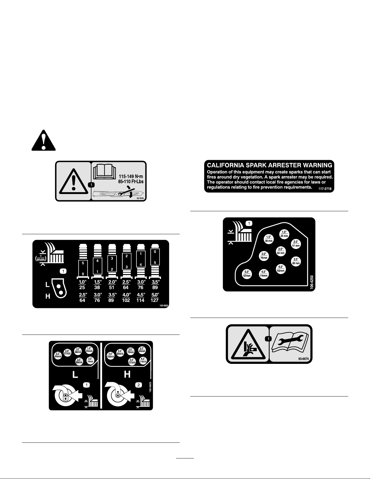
100-5622
1.Heightofcutadjustment
117–2718
106-4250
1.Heightofcut
93-6674
1.Lowheightofcut
adjustment
1.Crushinghazard,hand—readtheinstructionsbefore
servicingorperformingmaintenance.
100-5623
2.Highheightofcut
adjustment
7
Page 8
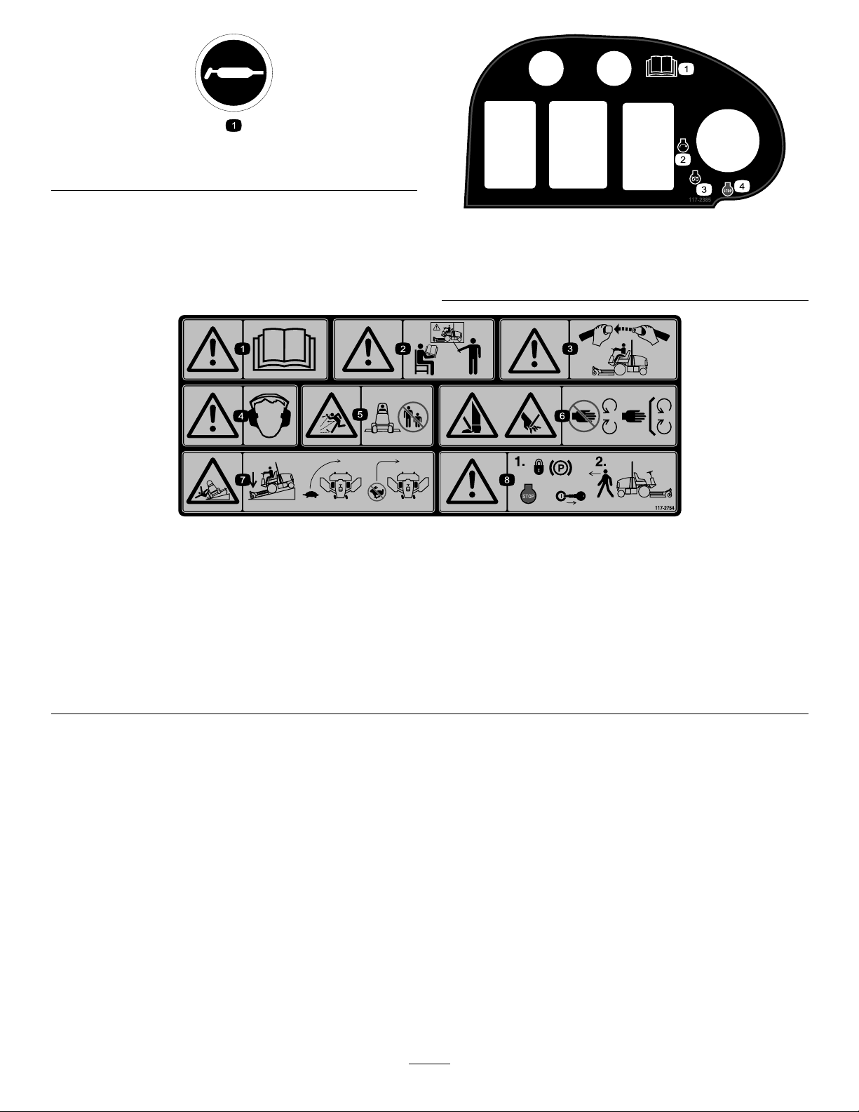
58-6520
1.Grease
117–2385
1.ReadtheOperators
Manual.
2.Engine—start4.Engine—stop
3.Engine—preheat
117–2754
1.Warning—readtheOperator'sManual.
2.Warning—donotoperatethismachineunlessyouaretrained.
3.Warning—weartheseatbeltwhenseatedintheoperator'sposition.
4.Warning—wearhearingprotection.
5.Thrownobjecthazard—keepbystandersasafedistancefromthemachine.
6.Cuttinghazardofhandorfoot—stayawayfrommovingparts;keepallguardsinplace.
7.Tippinghazard—lowerthecuttingunitwhendrivingdownslopes;slowmachinebeforeturning,donotturnathighspeeds
8.Warning—locktheparkingbrake,stoptheengineandremovetheignitionkeybeforeleavingthemachine.
8
Page 9
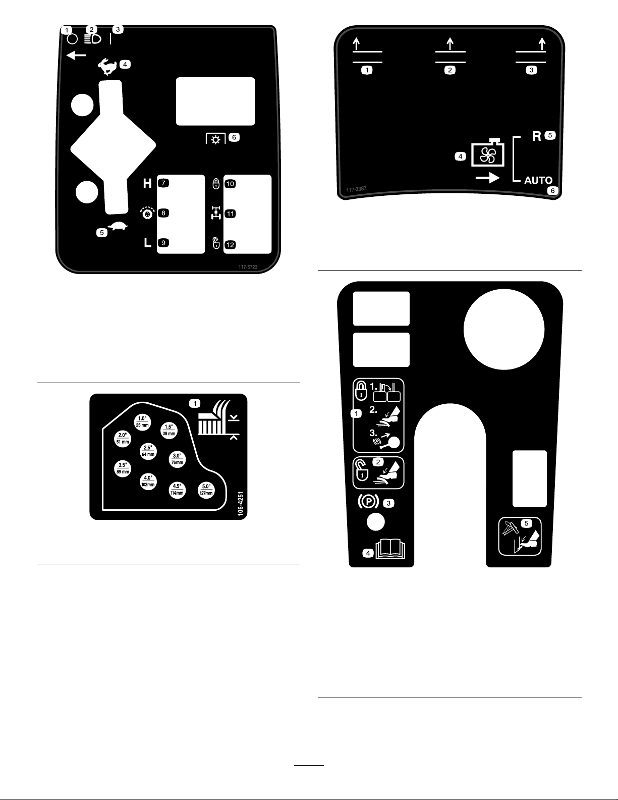
117–2387
1.Raiseleftdeck4.Coolingfan
2.Raisecenterdeck5.Reverse
3.Raiserightdeck6.Automatic
117-5723
1.Off
2.Headlights8.Tractioncontrol
3.On
4.Fast10.Locked
5.Slow
6.PowerT ake-off(PTO)
7.High
9.Low
11.Flowdivider
12.Unlocked
106-4251
1.Heightofcut
119-0067
1.Tolocktheparkingbrake,
latchthepedalstogether,
applythebrakepedals,
andpullupontheknob.
2.Tounlocktheparking
brake,steponthebrake
pedals.
3.Parkingbrakelock
indicator
9
4.ReadtheOperator's
Manual.
5.Pressdownontheleverto
tiltthesteeringwheel.
Page 10
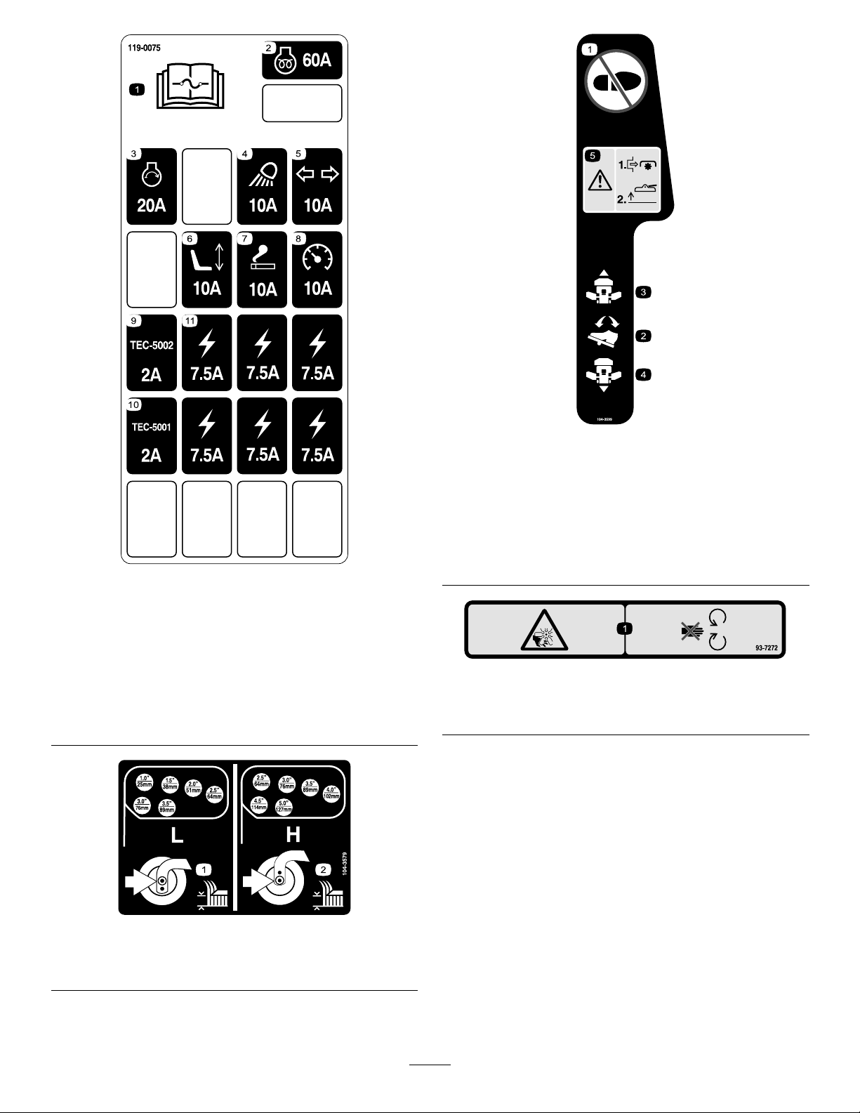
104-3599
1.Donotstephere.
2.Tractionpedal
3.Traction—forward
4.Traction—reverse
5.Danger—shutoffPTOpriortoraisingthecuttingunits;do
notoperatethecuttingunitswhentheyareintheraised
position.
119-0075
1.ReadtheOperator's
Manualforfuse
information.
2.Enginepreheat—60Afuse8.Instuments—10Afuse
3.Engine,start—20Afuse9.Controlmodule—2Afuse
4.Headlights—10Afuse10.Controlmodule—2Afuse
5.Turnsignal—10Afuse11.Powerpoint—7.5Afuse
6.Powerseat—10Afuse
7.Powerpoint—10Afuse
104-3579
1.Lowheightofcut
adjustment
2.Highheightofcut
adjustment
93-7272
1.Cutting/dismembermenthazard;fan—stayawayfromoving
parts.
10
Page 11
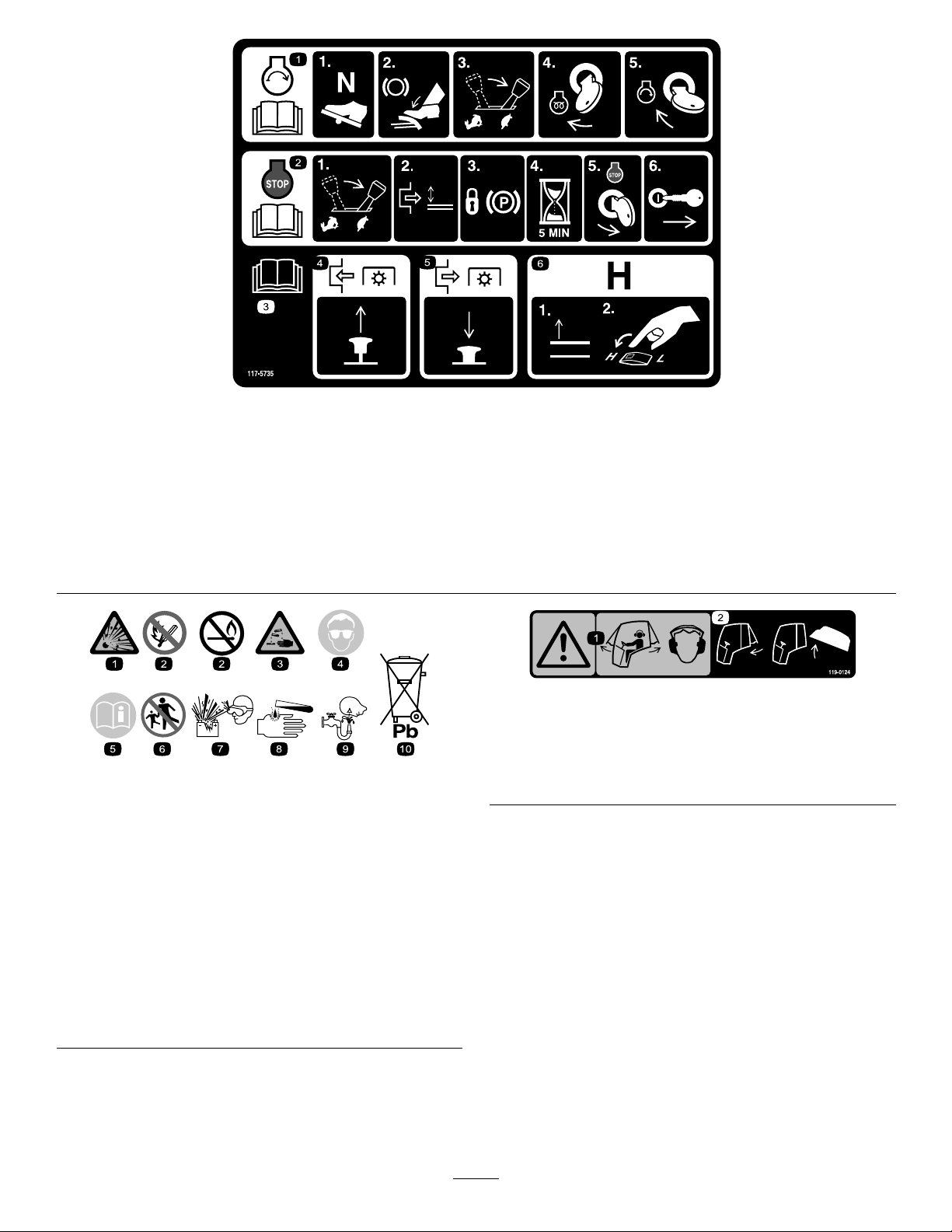
117-5735
1.ReadtheOperatorsManual;tostarttheengine,movethetractionpedaltoNeutral,applythebrake,movethethrottleswitchto
slow,turntheignitionkeytoPreheat.WhentheWaittoStartAdvisoryclearsontheInfoCenterthenturntheignitionkeytoStart.
2.ReadtheOperatorsManual;tostoptheengine,movethethrottlelevertoslow,disengagethePTO,settheparkingbrake,wait5
minutes,turntheignitionkeytoStop,andremovethekey;readtheOperatorsManual.
3.ReadtheOperatorsManual.
4.ToengagethePTO,pulluponthePTOswitch.
5.TodisengagethePTO,pushdownonthePTOswitch.
6.Toswitchthetransmissiontohighspeed,fullyraisetheattachmentsandswitchthespeedcontroltoHigh.
119–0124
(Model30447only)
1.Warning—whenthecabwindowsareopenwearhearing
BatterySymbols
Someorallofthesesymbolsareonyourbattery
protection.
2.Closetherearwindowbeforeattemptingtoopenthehood.
1.Explosionhazard
2.Nore,opename,or
smoking.
3.Causticliquid/chemical
burnhazard
4.Weareyeprotection9.Flusheyesimmediately
5.ReadtheOperator's
Manual.
6.Keepbystandersasafe
7.Weareyeprotection;
8.Batteryacidcancause
10.Containslead;donot
distancefromthebattery .
explosivegasescan
causeblindnessandother
injuries
blindnessorsevereburns.
withwaterandgetmedical
helpfast.
discard.
11
Page 12
1.ReadtheOperator'sManual.
106-6754
1.Warning—donottouchthehotsurface.
2.Cutting/dismembermenthazard,fanandentanglement
hazard,belt—stayawayfrommovingparts.
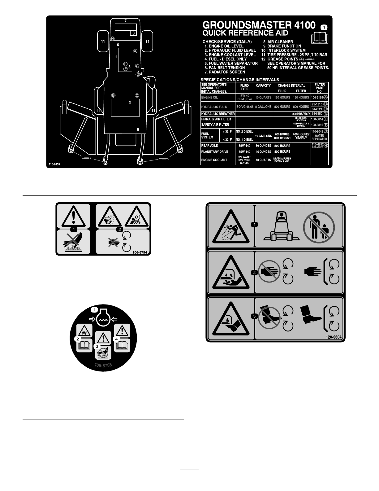
115-8455
120-6604
1.Enginecoolantunder
pressure.
2.Explosionhazard—read
theOperator'sManual.
106-6755
3.Warning—donottouchthe
hotsurface.
4.Warning—readthe
Operator'sManual.
1.Thrownobjecthazard—keepbystandersawayfromthe
machine.
2.Cutting/dismembermenthazardofhand,mower
blade—stayawayfrommovingparts,keepallguardsand
shieldsinplace.
3.Cutting/dismembermenthazardoffoot,mowerblade—stay
awayfrommovingparts,keepallguardsandshieldsin
place.
12
Page 13

Setup
MediaandAdditionalParts
Description
Operator'sManual
EngineOperator'sManual
PartsCatalog
OperatorTrainingMaterials
Pre-deliveryInspectionSheet
Note:Determinetheleftandrightsidesofthemachine
fromthenormaloperatingposition.
Qty.
GreasingtheMachine
Beforethemachineisoperated,itmustbegreasedtoensure
properlubricatingcharacteristics;refertoGreasingthe
BearingsandBushingsprocedureinLubrication.Failureto
properlygreasethemachinewillresultinprematurefailureof
criticalparts.
Use
1
1
1
1
1
Reviewbeforeoperatingmachine
Usetoreferenceengineinformation
Usetoreferencepartnumbers
Reviewbeforeoperatingmachine
13
Page 14
ProductOverview
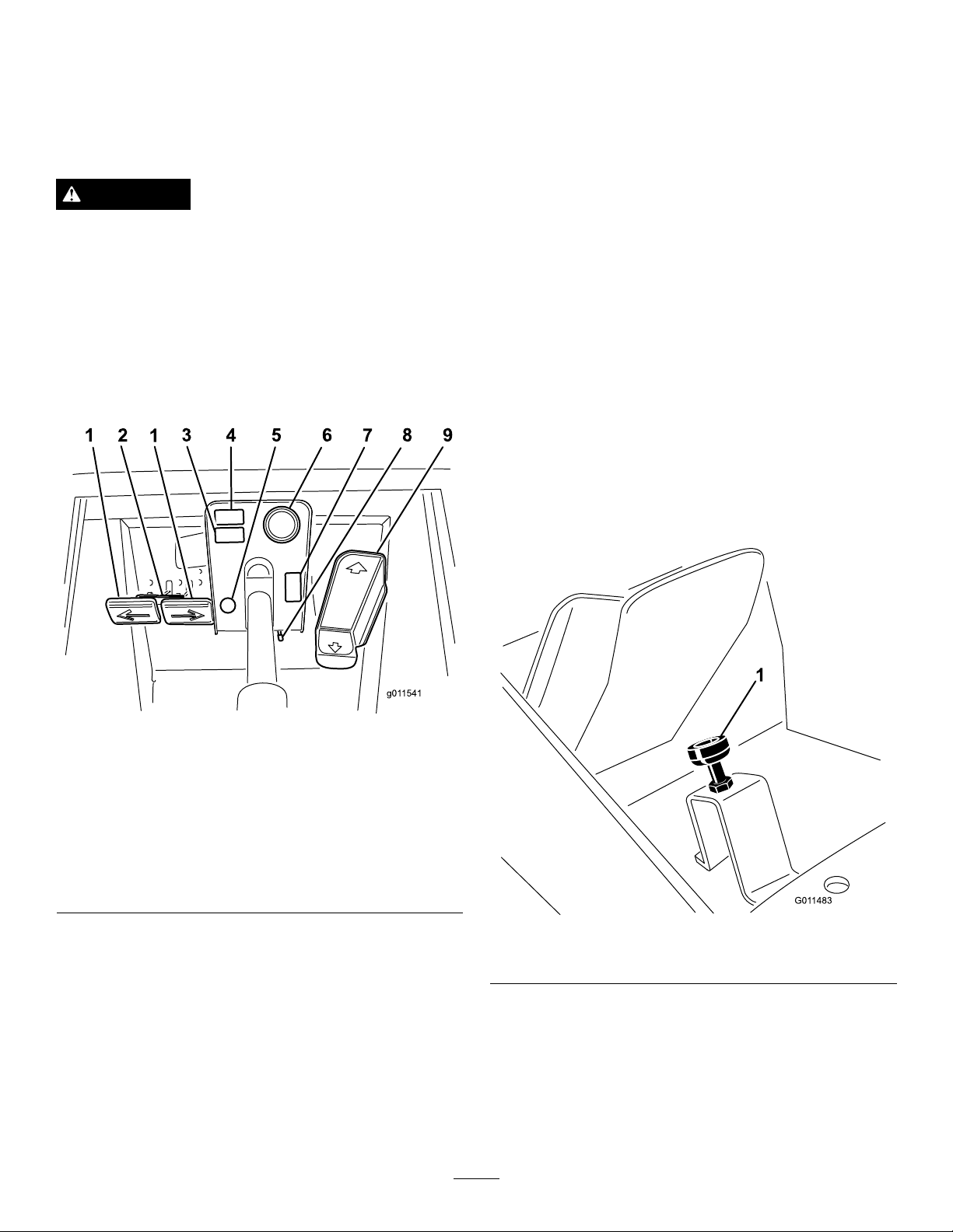
Controls
Note:Determinetheleftandrightsidesofthemachine
fromthenormaloperatingposition.
TiltSteeringLever
PresstheleverFigure2downtotiltthesteeringwheelto
thedesiredposition.Thenreleasethelevertolockthe
adjustment.
ParkingBrakeLatch
CAUTION
Thismachineproducessoundlevelsinexcessof85
dBAattheoperatorsearandcancausehearingloss
throughextendedperiodsofexposure.
Wearhearingprotectionwhenoperatingthis
machine.
TractionPedal
Tostop,reduceyourfootpressureonthetractionpedaland
allowittoreturntothecenterposition(Figure2).
Aknobontheleftsideoftheconsoleactuatestheparking
brakelock(Figure2).Toengagetheparkingbrake,connect
thepedalswiththelockinglatch,pushdownonbothpedals,
andpulltheparkingbrakelatchout.Toreleasetheparking
brake,pressbothpedalsuntiltheparkingbrakelatchretracts.
FuelGauge
Thefuelgauge(Figure2)indicatestheleveloffuelinthetank.
HazardLightSwitch(GM4100only)
Pressthehazardlightswitch(Figure2)toactivatethehazard
lights.
SpeedLimiter
Ifdesired,thescrewcanbeadjusted(Figure3)tolimitthe
amountthetractionpedalcanbedepressedintheforward
directiontolimitthemowingspeed.
Figure2
1.Brakepedals6.Fuelgauge
2.Pedallockinglatch
3.Spaceforoptional
accessory
4.Spaceforoptional
accessory
5.Parkingbrakelatch
7.Hazardlightswitch(GM
4100only)
8.Tiltsteeringlever
9.Tractionpedal
BrakePedals
TwofootpedalsFigure2operateindividualwheelbrakesfor
turningassistance,parking,andtoaidinobtainingbetterside
hilltraction.Alatchconnectsthepedalsforparkingbrake
operationandtransport.
PedalLockingLatch
ThepedallockinglatchFigure2connectsthepedalstogether
toengagetheparkingbrake.
Figure3
1.Speedlimiter
Important:Wheninthemowposition,thespeedlimiter
screwmuststopthetractionpedalbeforethepump
reachesfullstrokeordamagetothepumpmayoccur.
DiagnosticLight
Thediagnosticlight(Figure4)willilluminateshouldasystem
faultberecognized.
14
Page 15
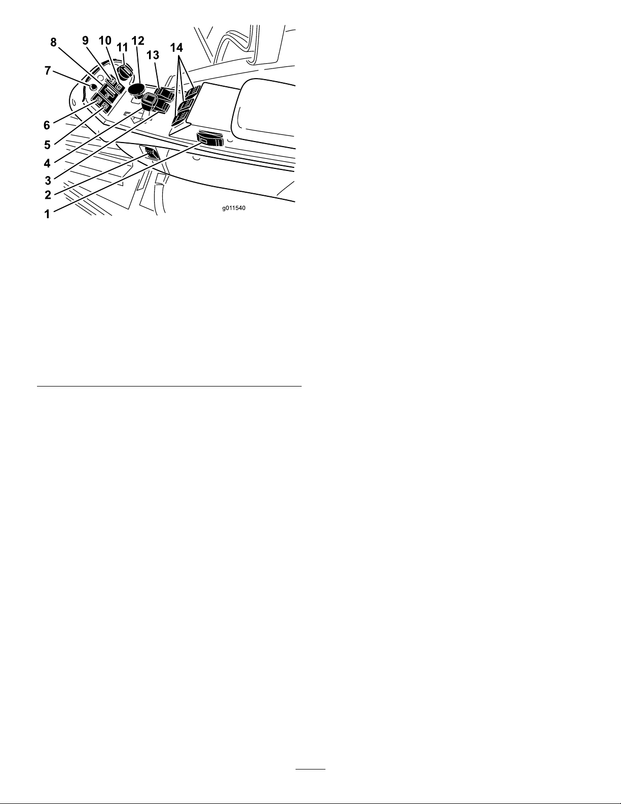
Figure4
FlowDividerSwitch(optional)
Whenoperatinginmow(low)speed,pressandhold
owdividerswitch(Figure4)toenhancetractiondrive
performanceincompromisedoperatingconditions.
Hi-LoSpeedControl
Theswitch(Figure4)allowsthespeedrangetoincreasefor
transportofthemachine.Cuttingdeckswillnotoperate
inhighrange.Also,thedeckscannotbeloweredfromthe
transportpositionwhentheswitchisinthehighrange.If
theswitchismovedfromLOtoHIwiththecuttingdecks
downand/orPTOonand/orcruisecontrolengaged,the
transmissionwillnotchangetoHI.Forthechangetobe
accomplished,theswitchmustbemovedtoLOandallthe
requirementssatised.
1.Cruisecontrol(optional)
2.Lightswitch9.Engineoilpressure
3.Hi-Lospeedcontrol
4.Throttlecontrol11.Keyswitch
5.Glowplugindicatorlight12.PTOswitch
6.Enginecoolant
temperaturewarning
light
7.Diagnosticlight
8.Enginecoolant
temperaturegauge
warninglight
10.Chargeindicator
13.Flowdividerswitch
(optional)
14.Liftswitches
EngineCoolantTemperatureGauge
Duringnormaloperatingconditionsthegauge(Figure4)
shouldbeinthegreenrange.Checkthecoolingsystemifthe
gaugegoestotheyelloworredrange.
EngineOilPressureWarningLight
Thelight(Figure4)illuminateswhentheengineoilpressure
isdangerouslylow.
LiftSwitches
Theliftswitches(Figure4)raiseandlowerthecutting
units.Presstheswitchesforwardtolowerthecuttingunits
andbackwardtoraisethecuttingunits.Whenstartingthe
machine,withthecuttingunitsinthedownposition,pressthe
liftswitchdowntoallowthecuttingunitstooatandmow.
Note:ThedeckswillnotlowerwhileintheHIspeedrange
andtheywillnotraiseorloweriftheoperatorisoutofthe
seatwhentheengineisrunning.
ThrottleControl
Movethecontrol(Figure4)forwardtoincreasetheengine
speedandrearwardtodecreasethespeed.
LightSwitch
Presstheloweredgeoftheswitch(Figure4)toturnonthe
lights.Presstheupperedgeoftheswitchtoturnoffthelights.
GlowPlugIndicatorLight
ChargeIndicator
Thechargeindicator(Figure4)illuminateswhenthesystem
chargingcircuitmalfunctions.
KeySwitch
Thekeyswitch(Figure4)hasthreepositions:Off,
On/Preheat,andStart.
PTOSwitch
ThePTOswitch(Figure4)hastwopositions:Out(start)
andIn(stop).PullthePTObuttonouttoengagethecutting
unitblades.Pushinthebuttontodisengagethecuttingunit
blades.
Whenlit,theglowplugindicatorlight(Figure4)indicates
thattheglowplugsareon.
EngineCoolantTemperatureWarning
Light
Thelight(Figure4)illuminatesandthecuttingunitsshut
down(PTOdisengages)iftheenginereachesanunsafe
operatingtemperature.Ifthetemperaturecontinuestorise
theenginewillshutdown.
EngineCoolingFanSwitch
Themachineisequippedwithahydraulicallydrivenauto
reversingenginecoolingfan.Thefanswitch(Figure5)has
15
Page 16

twopositionsR(manualreverse)andAuto(normal).Refer
G011547
1
2
3
toEngineCoolingFanOperationintheOperationSection
ofmanual.
Figure5
1.Powerpoint3.Hourmeter
2.Enginecoolingfanswitch
FanControl
Rotatethefancontrolknobtoregulatethespeedofthefan
(Figure6).
TemperatureControl
Rotatethetemperaturecontrolknobtoregulatetheair
temperatureinthecab(Figure6).
HourMeter
Thehourmeter(Figure5)showsthetotalhoursthatthe
machinehasbeenoperated.
PowerPoint
Thepowerpoint(Figure5)isusedtopoweroptional
electricalaccessories.
AudibleAlarm
Towarnbystanders,analarmwillsoundifthecuttingdecks
areloweredwiththeengineoff.Thealarmwillquitsounding
oncethedecklowerswitchisreleased.Also,thealarmwill
soundiftheenginecoolanttemperaturereachesaset-point
thatcutsoutthePTOoperation.Thealarmwillcontinue
tosounduntilthecoolanttemperaturedropsbelowthe
set-pointorthePTOswitchisdisengaged.
CabControls
Model30447only
Figure6
1.Windshieldwiperswitch5.Hazardlightswitch
2.Airconditioningswitch6.Turnsignalswitch
3.Temperaturecontrol7.Domelightswitch
4.Fancontrol
HazardLightSwitch
Presstheswitchtoactivatethehazardlights(Figure6).
TurnSignalSwitch
Presstheswitchtoactivatetheturnsignals(Figure6).
DomeLightSwitch
Presstheswitchtoactivatethedomelight(Figure6).
WindShieldLatch
WindShieldWiperSwitch
Pressfrontofswitchtoactivatethewindshieldwipers
(Figure6)andrearofswitchtoturnoffthewipers.
AirConditioningSwitch
Pressfrontofswitchtoactivatetheairconditioning(Figure6)
andrearofswitchtoturnofftheairconditioning.
Liftuponlatchestoopenthewindshield(Figure7).Press
inonlatchtolockwindshieldinopenposition.Pulloutand
downonlatchtocloseandsecurewindshield.
16
Page 17
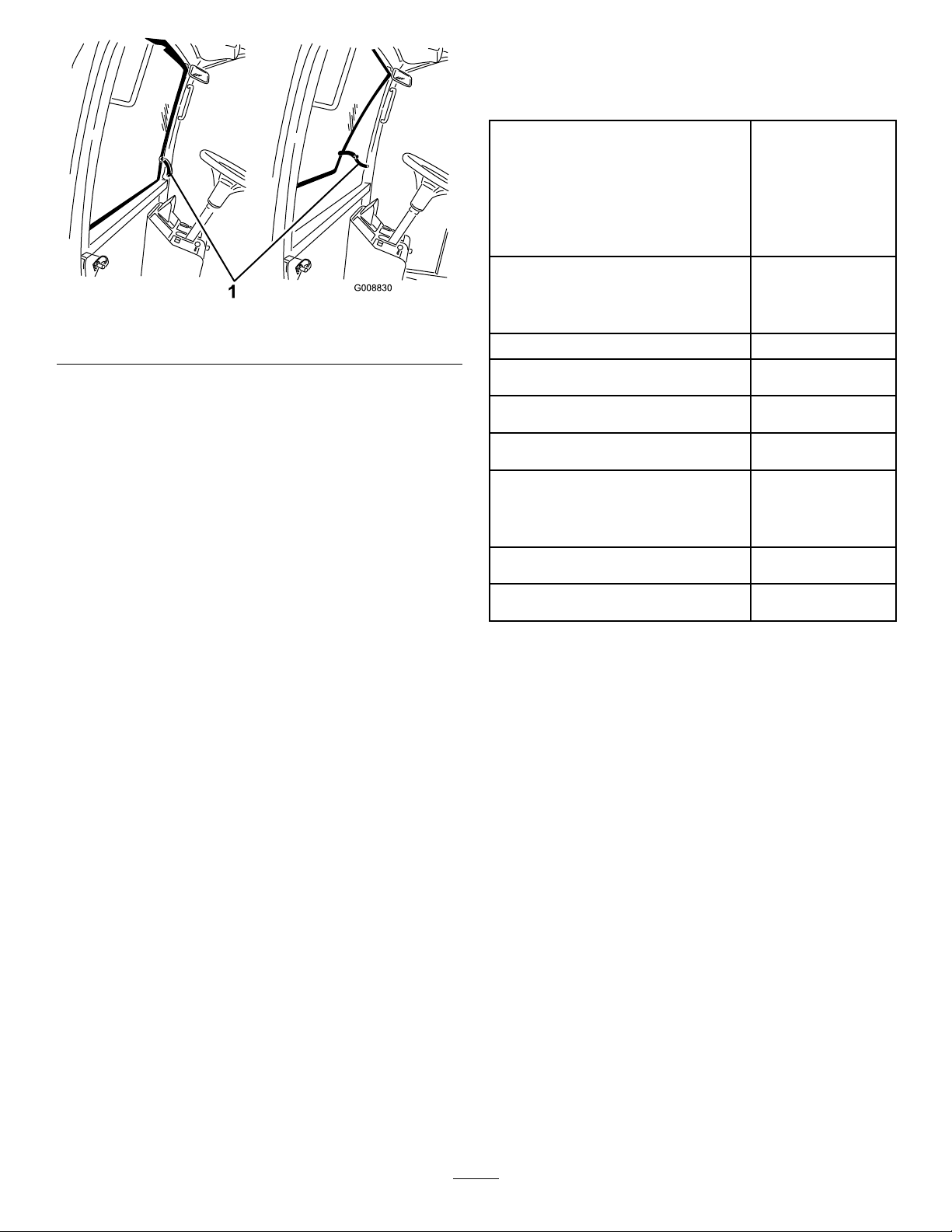
1.Windshieldlatch
Figure7
Specications
Note:Specicationsanddesignaresubjecttochange
withoutnotice.
Widthofcut
overall
frontcuttingunit54inch(137cm)
sidecuttingunit
frontandonesidecuttingunit89inch(226cm)
Overallwidth
cuttingunitsdown
cuttingunitsup(transports)71inch(180cm)
Overalllength144inch(366cm)
Height
124inch(315cm)
37inch(94cm)
127inch(322cm)
58inch(147cm)
HeightwithROPS
Heightwithcab
Groundclearance6inch(15cm)
Wheeltread(tocenteroftire)
front45inch(1 14cm)
rear
Wheelbase
Weight(withcuttingunits)
(Weightwithcabwithcuttingunits)
81inch(206cm)
91inch(231cm)
47inch(1 19cm)
55-1/2inch(141cm)
4211lb(1910kg)
4715lb(2139kg)
Attachments/Accessories
AselectionofToroapprovedattachmentsandaccessoriesare
availableforusewiththemachinetoenhanceandexpand
itscapabilities.ContactyourAuthorizedServiceDealeror
Distributororgotowww .Toro.comforalistofallapproved
attachmentsandaccessories.
17
Page 18
Operation
Note:Determinetheleftandrightsidesofthemachine
fromthenormaloperatingposition.
BeforeOperating
CAUTION
Ifyouleavethekeyintheignitionswitch,someone
couldaccidentlystarttheengineandseriously
injureyouorotherbystanders.
Removethekeyfromtheignitionbeforeyoudoany
maintenance.
CheckingtheEngineOil
ServiceInterval:Beforeeachuseordaily
Theengineisshippedwithoilinthecrankcase;however,the
oillevelmustbecheckedbeforeandaftertheengineisrst
started.
Thecrankcasecapacityis10qt(9.5l)withthelter.
Usehigh-qualityengineoilthatmeetsthefollowing
specications:
•APIClassicationLevelRequired:CH-4,CI-4orhigher.
•Preferredoil:SAE15W-40(above0°F)
•Alternateoil:SAE10W-30or5W-30(alltemperatures)
ToroPremiumEngineOilisavailablefromyourdistributor
ineither15W -40or10W -30viscosity .Seethepartscatalog
forpartnumbers.
Note:Thebesttimetochecktheengineoiliswhenthe
engineiscoolbeforeithasbeenstartedfortheday.Ifithas
alreadybeenrun,allowtheoiltodrainbackdowntothe
sumpforatleast10minutesbeforechecking.Iftheoillevel
isatorbelowthe“add”markonthedipstick,addoiltobring
theoilleveltothe“full”mark.DONOTOVERFILL.If
theoillevelisbetweenthe“full”and“add”marks,nooil
additionisrequired.
1.Parkthemachineonalevelsurface.Unlocktheengine
coverlatches.
2.Opentheenginecover.
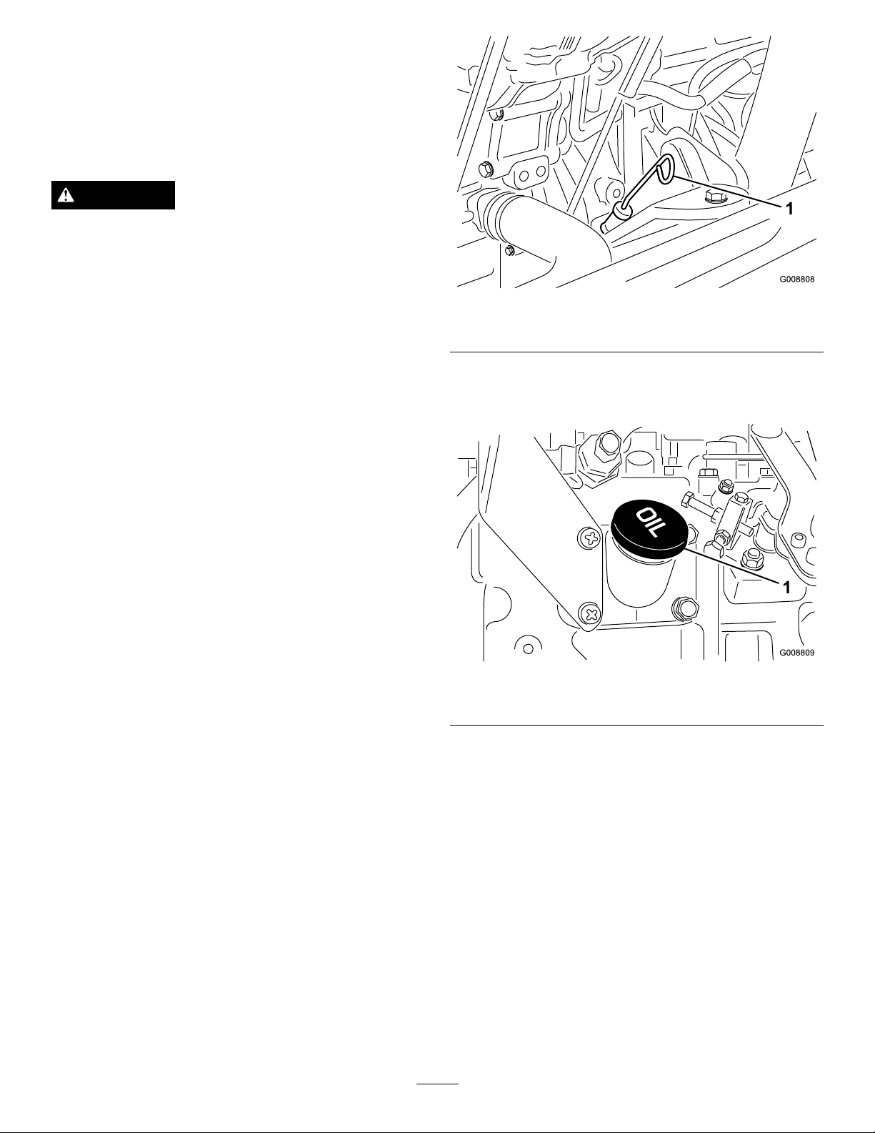
3.Removethedipstick,wipeitclean,installthedipstick
intothetube,andpullitoutagain.Theoillevelshould
beuptotheFULLmark(
Figure8).
Figure8
1.Dipstick
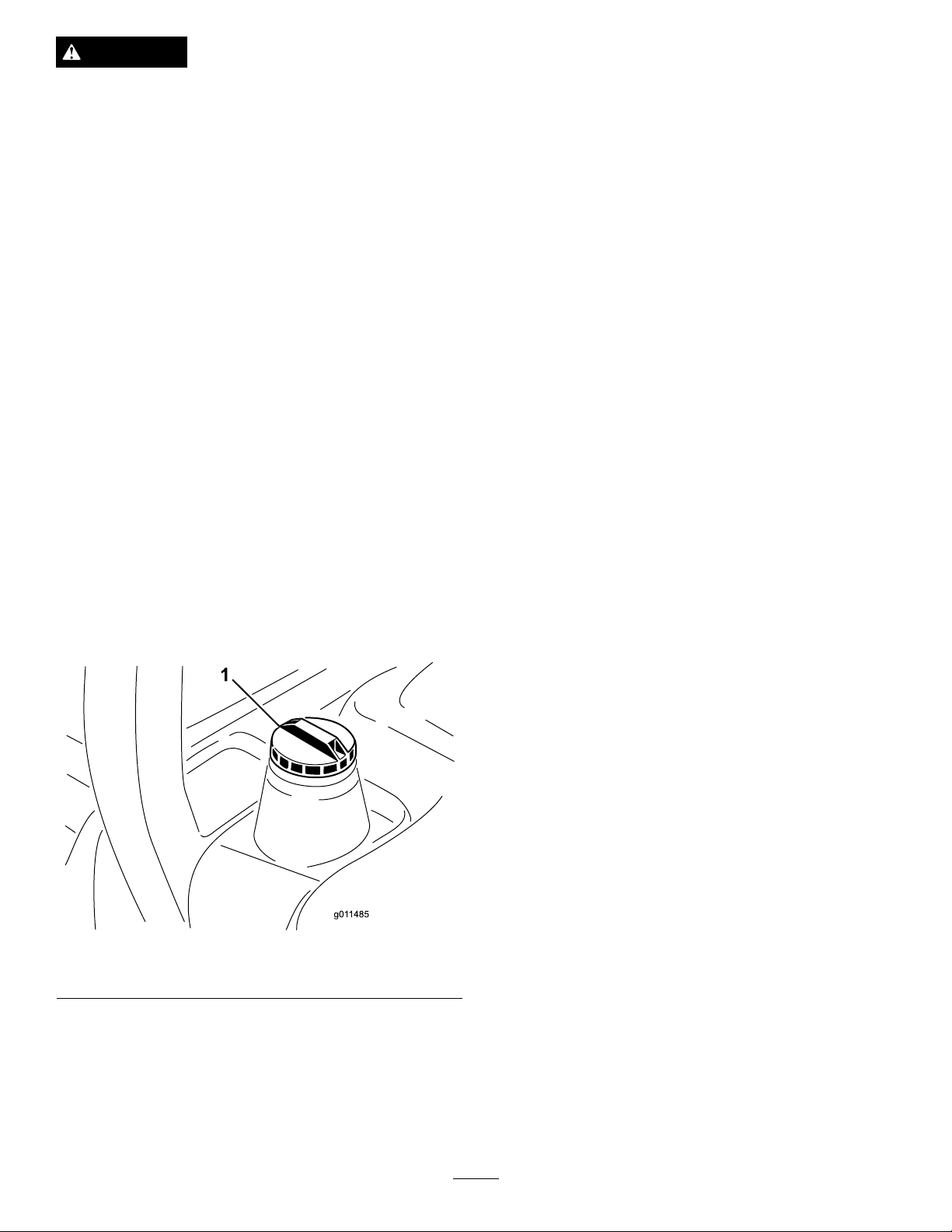
4.IftheoilisbelowtheFullmark,removethellcap
(Figure9)andaddoiluntilthelevelreachestheFull
mark.Donotoverll.
Figure9
1.Oilllcap
Note:Whenusingdifferentoil,drainalloldoilfrom
thecrankcasebeforeaddingnewoil.
5.Installtheoilllcapanddipstick.
6.Closetheenginecoverandsecureitwiththelatches.
CheckingtheCoolingSystem
ServiceInterval:Beforeeachuseordaily
Checklevelofcoolantatthebeginningofeachday .Capacity
ofsystemis13qts.(12.3l).
1.Carefullyremovetheradiatorcapandexpansiontank
cap(
Figure10).
18
Page 19
CAUTION
Iftheenginehasbeenrunning,the
pressurized,hotcoolantcanescapeandcause
burns.
•Donotopentheradiatorcapwhenthe
engineisrunning.
•Usearagwhenopeningtheradiatorcap,
andopenthecapslowlytoallowsteamto
escape.
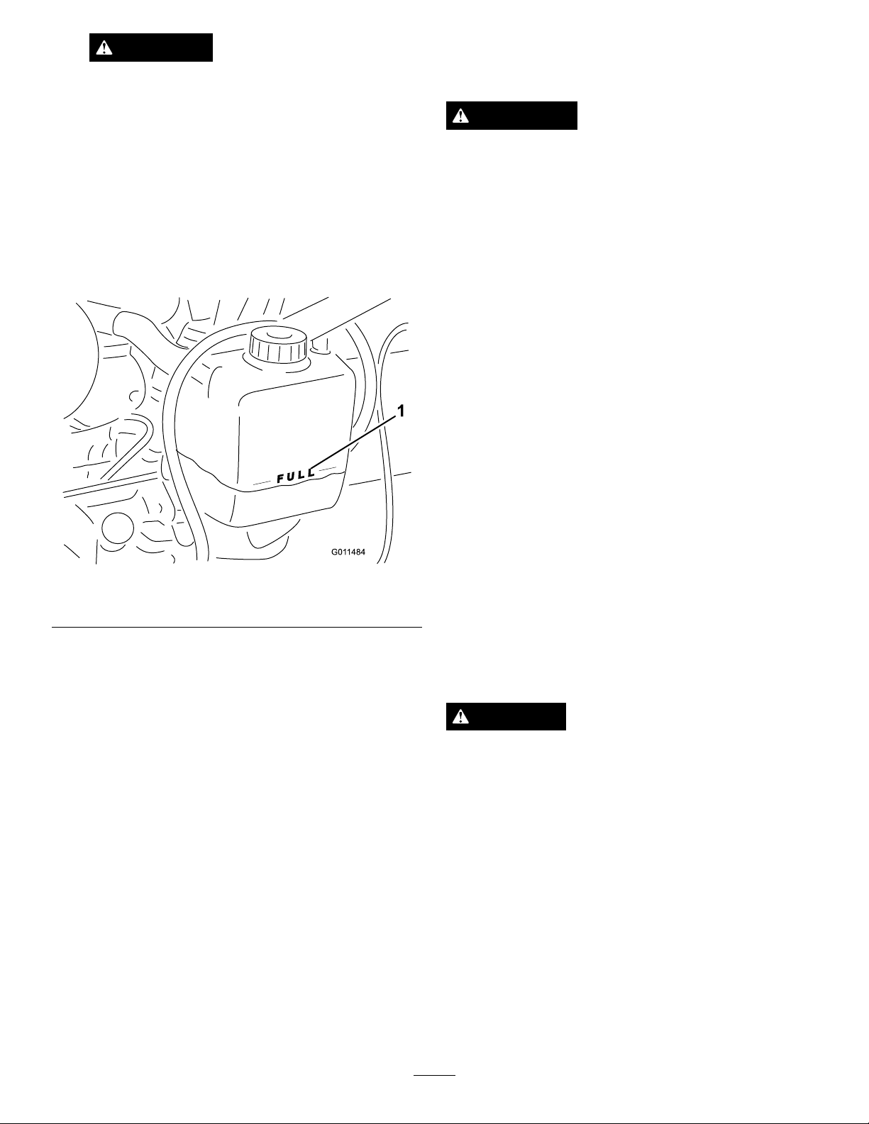
2.Checkthecoolantlevelintheradiator.Theradiator
shouldbelledtothetopofthellerneckandthe
expansiontanklledtotheFullmark.
Important:Donotusekeroseneorgasolineinsteadof
dieselfuel.Failuretoobservethiscautionwilldamage
theengine.
WARNING
Fuelisharmfulorfatalifswallowed.Long-term
exposuretovaporscancauseseriousinjuryand
illness.
•Avoidprolongedbreathingofvapors.
•Keepfaceawayfromnozzleandgastankor
conditioneropening .
•Keepfuelawayfromeyesandskin.
BiodieselReady
Thismachinecanalsouseabiodieselblendedfuelofup
toB20(20%biodiesel,80%petrodiesel).Thepetrodiesel
portionshouldbeloworultralowsulfur.Observethe
followingprecautions:
•Thebiodieselportionofthefuelmustmeetspecication
ASTMD6751orEN14214.
Figure10
1.Expansiontank
3.Ifthecoolantislow ,adda50/50mixtureofwaterand
ethyleneglycolanti-freeze.Donotusewateronlyor
alcohol/methanolbasecoolants.
4.Installtheradiatorcapandexpansiontankcap.
AddingFuel
Useonlyclean,freshdieselfuelorbiodieselfuelswithlow
(<500ppm)orultralow(<15ppm)sulfurcontent.The
minimumcetaneratingshouldbe40.Purchasefuelin
quantitiesthatcanbeusedwithin180daystoensurefuel
freshness.
Fueltankcapacity:19USgallons(72l)
Usesummergradedieselfuel(No.2-D)attemperatures
above20°F(-7°C)andwintergrade(No.1-DorNo.
1-D/2-Dblend)belowthattemperature.Useofwintergrade
fuelatlowertemperaturesprovideslowerashpointand
coldowcharacteristicswhichwilleasestartingandreduce
fuellterplugging.
Useofsummergradefuelabove20°F(-7°C)willcontribute
towardlongerfuelpumplifeandincreasedpowercompared
towintergradefuel.
•TheblendedfuelcompositionshouldmeetASTMD975
orEN590.
•Paintedsurfacesmaybedamagedbybiodieselblends.
•UseB5(biodieselcontentof5%)orlesserblendsincold
weather.
•Monitorseals,hoses,gasketsincontactwithfuelasthey
maybedegradedovertime.
•Fuellterpluggingmaybeexpectedforatimeafter
convertingtobiodieselblendsd.
•Contactyourdistributorifyouwishformoreinformation
onbiodiesel.
DANGER
Incertainconditions,fuelisextremelyammable
andhighlyexplosive.Areorexplosionfromfuel
canburnyouandothersandcandamageproperty.
•Fillthefueltankoutdoors,inanopenarea,when
theengineiscold.Wipeupanyfuelthatspills.
•Neverllthefueltankinsideanenclosedtrailer.
•Neversmokewhenhandlingfuel,andstayaway
fromanopenameorwherefuelfumesmaybe
ignitedbyaspark.
•Storefuelinanapprovedcontainerandkeepit
outofthereachofchildren.Neverbuymore
thana30-daysupplyoffuel.
•Donotoperatewithoutentireexhaustsystemin
placeandinproperworkingcondition.
19
Page 20
DANGER
Incertainconditionsduringfueling,static
electricitycanbereleasedcausingasparkwhich
canignitethefuelvapors.Areorexplosionfrom
fuelcanburnyouandothersandcandamage
property.
•Alwaysplacefuelcontainersonthegroundaway
fromyourvehiclebeforelling.
•Donotllfuelcontainersinsideavehicleoron
atruckortrailerbedbecauseinteriorcarpets
orplastictruckbedlinersmayinsulatethe
containerandslowthelossofanystaticcharge.
•Whenpractical,removeequipmentfromthe
truckortrailerandrefueltheequipmentwithits
wheelsontheground.
•Ifthisisnotpossible,thenrefuelsuch
equipmentonatruckortrailerfromaportable
container,ratherthanfromafueldispenser
nozzle.
•Ifafueldispensernozzlemustbeused,keepthe
nozzleincontactwiththerimofthefueltank
orcontaineropeningatalltimesuntilfuelingis
complete.
1.Parkthemachineonalevelsurface.
2.Usingacleanrag,cleanareaaroundfueltankcap.
3.Removecapfromthefueltank(Figure11).
CheckingtheHydraulicFluid
ServiceInterval:Beforeeachuseordaily
Themachinesreservoirislledatthefactorywith
approximately8U.S.gallons(30.2l)ofhighqualityhydraulic
uid.Checkthelevelofthehydraulicuidbefore
theengineisrststartedanddailythereafter.The
recommendedreplacementuidis:
ToroPremiumAllSeasonHydraulicFluid(Availablein
5gallonpailsor55gallondrums.SeepartscatalogorToro
distributorforpartnumbers.)
Alternateuids:IftheTorouidisnotavailable,otheruids
maybeusedprovidedtheymeetallthefollowingmaterial
propertiesandindustryspecications.W edonotrecommend
theuseofsyntheticuid.Consultwithyourlubricant
distributortoidentifyasatisfactoryproduct.
Note:Torowillnotassumeresponsibilityfordamage
causedbyimpropersubstitutions,souseonlyproducts
fromreputablemanufacturerswhowillstandbehindtheir
recommendation.
HighViscosityIndex/LowPourPointAnti-wear
HydraulicFluid,ISOVG46
MaterialProperties:
St@40°C44to48 Viscosity,ASTMD445
St@100°C7.9to8.5
ViscosityIndexASTMD2270
PourPoint,ASTMD97-34°Fto-49°F
IndustrySpecications:VickersI-286-S(Quality
Level),VickersM-2950-S
(QualityLevel),Denison
140to160
HF-0
Figure11
1.Fueltankcap
4.Fillthetankuntilthelevelistothebottomoftheller
neckwithdieselfuel.
5.Installfueltankcaptightlyafterllingtank.
Note:Ifpossible,llthefueltankaftereachuse.This
willminimizepossiblebuildupofcondensationinside
thefueltank.
Note:Manyhydraulicuidsarealmostcolorless,makingit
difculttospotleaks.Areddyeadditiveforthehydraulic
systemoilisavailablein2/3oz(20ml)bottles.Onebottle
issufcientfor4-6gallons(15-221)ofhydraulicoil.Order
partno.44-2500fromyourauthorizedTorodistributor.
1.Positionthemachineonalevelsurface,lowerthe
cuttingunits,stoptheengine,andremovethekey.
2.Unlatchtheseat,raiseit,andengagetheproprod.
3.Cleantheareaaroundthellerneckandcapofthe
hydraulictank(
llerneck.
20
Figure12).Removethecapfromthe
Page 21
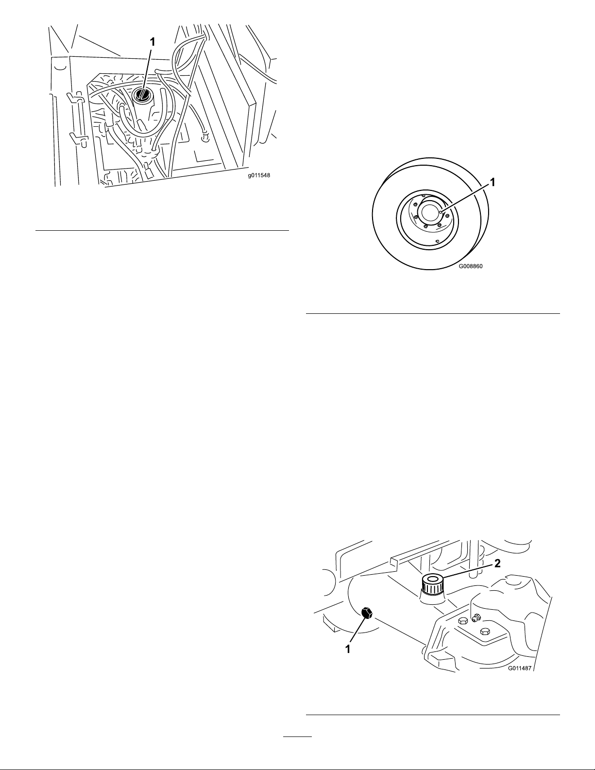
Figure12
1.Hydraulictankcap
4.Removethedipstickfromthellerneckandwipeit
withacleanrag.Insertthedipstickintothellerneck;
thenremoveitandchecktheuidlevel.Theuidlevel
shouldbebetweenthetwomarksonthedipstick.
CheckingthePlanetaryGearDriveOil
ServiceInterval:Every400hours
Checktheoillevelafterevery400hoursofoperationorif
externalleakageisnoted.UsehighqualitySAE85W -140gear
lubeasareplacement.
Thecapacityofthesystemisapproximately16oz(0.5l).
1.Withthemachineonalevelsurface,positionthewheel
sothatthecheck/drainplug(Figure13)isateitherthe
3or9o'clockposition.
Figure13
5.Ifthelevelislow ,addtheappropriateuidtoraisethe
leveltotheuppermark.
6.Installthedipstickandcapontothellerneck.
1.Check/drainplug
2.Addgearoiltotheholeintheplanetary,ifnecessary,
tobringtheoiluptotheproperlevel.Installtheplug.
3.Repeattheprocedureontheoppositegearassembly.
CheckingtheRearAxleLubricant
ServiceInterval:Every400hours
TherearaxleislledwithSAE85W-140gearlube.Checkthe
oillevelbeforetheengineisrststartedandevery400hours
thereafter.Thecapacityis80oz(2.4l).Visuallyinspectfor
leaksdaily.
1.Positionthemachineonalevelsurface.
2.Removeacheckplugfromoneendoftheaxle
Figure14)andmakesurethatthelubricantisuptothe
(
bottomofthehole.Ifthelevelislow ,removethell
plug(Figure14)andaddenoughlubricanttobringthe
leveluptothebottomofthecheckplugholes.
Figure14
1.Checkplug
21
2.Fillplug
Page 22

CheckingtheRearAxleGearBox
Lubricant
ServiceInterval:Every400hours
ThegearboxislledwithSAE85W -140gearlube.Check
theoillevelbeforetheengineisrststartedandevery400
hoursthereafter.Thecapacityis16oz(0.5l).Visuallyinspect
forleaksdaily.
1.Positionthemachineonalevelsurface.
2.Removethecheck/llplugfromtheleftsideofthe
gearbox(Figure15)andmakesurethatlubricantis
uptothebottomofthehole.Ifthelevelislow,add
enoughlubricanttobringtheleveluptothebottom
ofthehole.
CheckingtheTirePressure
ServiceInterval:Beforeeachuseordaily
Thetiresareover-inatedforshipping.Therefore,release
someoftheairtoreducethepressure.Thecorrectair
pressureinthefrontandreartiresis25-30psi(172-207kPa).
Important:Maintainevenpressureinalltirestoensure
agoodquality-of-cutandpropermachineperformance.
Do not under -inate.
CheckingtheTorqueoftheWheelNuts
orBolts
ServiceInterval:Aftertherst10hours
Every200hours
WARNING
Failuretomaintainpropertorqueofthewheelnuts
couldresultinfailureorlossofwheelandmay
resultinpersonalinjury.
Torquethefrontwheelnutsandrearboltsto85-100
ft-lb(115-136N⋅ ⋅⋅m)after1-4hoursofoperationand
againafter10hoursofoperation.T orqueevery200
hoursthereafter.
Figure15
1.Gearbox2.Check/llplug
AdjustingtheHeight-of-Cut
CenterCuttingUnit
Theheight-of-cutisadjustablefrom1to5inches(25to
127mm)in1/2inch(13mm)increments.Toadjustthe
height-of-cutonthefrontcuttingunit,positionthecastor
wheelaxlesintheupperorlowerholesofthecastorforks,
addorremoveanequalnumberofspacersfromthecastor
forks,andsecuretherearchaintothedesiredhole.
1.Starttheengineandraisethecuttingunitssothatthe
height-of-cutcanbechanged.Stoptheengineand
removethekeyafterthecuttingunitisraised.
2.Positionthecastorwheelaxlesinthesameholesinall
castorforks.Refertothefollowingcharttodetermine
thecorrectholesforthesetting.
22
Page 23

Figure16
5.Removethehairpincotterandclevispinsecuringthe
height-of-cutchainstotherearofthecuttingunit
(
Figure18).
1.Tensioningcap4.Topaxlemountinghole
2.Spacers5.Castorwheel
3.Shims
Note:Whenoperatingin2-1/2inch(64mm)height
ofcutorhigher,theaxleboltmustbeinstalledinthe
lowercastorforkholetopreventgrassbuildupbetween
thewheelandthefork.Whenoperatinginheight
ofcutslowerthan2-1/2inches(64mm)andgrass
buildupisdetected,reversethemachinesdirectionto
pullanyclippingsawayfromthewheel/forkarea.
3.Removethetensioningcapfromthespindleshaft
(Figure16)andslidethespindleoutofthecastorarm.
Putthe2shims(1/8inch[3mm])ontothespindle
shaftastheywereoriginallyinstalled.Theseshimsare
requiredtoachievealevelacrosstheentirewidthof
thecuttingunits.Slidetheappropriatenumberof1/2
inchspacers(refertothechartbelow)ontothespindle
shafttogetthedesiredheight-of-cut;thenslidethe
washerontotheshaft.
Refertothefollowingcharttodeterminethe
combinationsofspacersforthesetting:
Figure18
1.Height-of-cutchain2.Clevispin&hairpincotter
6.Mounttheheight-of-cutchainstothedesired
height-of-cuthole(
Figure19)withtheclevispinand
hairpincotter.
Figure19
Note:Whenusing1inch(25mm),1-1/2inch(38
mm),oroccasionally2inch(51mm)height-of-cut,
movetheskidsandgagewheelstothehighestposition.
Figure17
4.Pushthecastorspindlethroughthefrontcastorarm.
Installtheshims(astheywereoriginallyinstalled)and
theremainingspacersontothespindleshaft.Installthe
tensioningcaptosecuretheassembly .
WingCuttingUnits
Toadjusttheheight-of-cutonthesidecuttingunits,add
orremoveanequalnumberofspacersfromthecastor
forks,positionthecastorwheelaxlesinthehighorlow
height-of-cutholesinthecastorforks,andsecurethepivot
armstotheselectedheight-of-cutbracketholes.
1.Positionthecastorwheelaxlesinthesameholesinall
ofthecastorforks(Figure20andFigure22).Referto
thefollowingcharttodeterminethecorrectholefor
thesetting.
2.Removethetensioningcapfromthespindleshaft
(
Figure20)andslidethespindleoutofcastorarm.Put
thetwoshims(1/8inch[3mm])ontospindleshaftas
theywereoriginallyinstalled.Theseshimsarerequired
toachievealevelacrosstheentirewidthofthecutting
units.Slidetheappropriatenumberof1/2inchspacers
23
Page 24

ontothespindleshafttogetthedesiredheight-of-cut;
thenslidethewasherontotheshaft.
Figure22
Figure20
1.Tensioningcap4.Topaxlemountinghole
2.Spacers5.Castorwheel
3.Shims
Refertothefollowingcharttodeterminethe
combinationsofspacersforthesetting.
Figure21
3.Pushthecastorspindlethroughthecastorarm.Install
theshims(asoriginallyinstalled)andtheremaining
spacersontothespindleshaft.Installthetensioning
captosecuretheassembly .
4.Removethehairpincotterandclevispinsfromthe
castorpivotarms(Figure22).
1.Castorpivotarm3.Clevispinandhairpin
cotter
2.Axlemountingholes4.T ensionrod
Figure23
AdjustingtheSkids
Theskidsshouldbemountedinthelowerpositionwhen
operatinginheightofcutsgreaterthan2-1/2inches(64mm)
andinthehigherpositionwhenoperatinginheightofcuts
lowerthan2-1/2inches(64mm).
Adjusttheskidsbyremovingtheangeboltandnuts,
positioningthemasdesired,andinstallingthefasteners
(Figure24).
5.Rotatetensionrodtoraiseorlowerpivotarm
untilholesarealignedwithselectedheight-of-cut
bracketholesinthecuttingunitframe(Figure22and
Figure23).
6.Inserttheclevispinsandinstallthehairpincotters.
7.Rotatetensionrodcounterclockwise(ngertight)to
puttensiononadjustment.
Figure24
1.Skid
24
Page 25

AdjustingtheCuttingUnitRollers
Thecuttingunitrollersshouldbemountedinthelower
positionwhenoperatinginheightofcutsgreaterthan2-1/2
inches(64mm)andinthehigherpositionwhenoperatingin
heightofcutslowerthan2-1/2inches(64mm).
1.Removetheboltandnutsecuringthegagewheelto
thecuttingunitbrackets(Figure25).
Figure25
1.Gagewheel
2.Aligntherollerandspacerwiththetopholesinthe
bracketsandsecurethemwiththeboltandnut.
Figure27
1.Adjusterbolt2.Jamnut
CorrectingMismatchBetweenCutting
Units
Duetodifferencesingrassconditionsandthecounterbalance
settingofthetractionunit,itisadvisedthatasampleareaof
grassbecutandappearancecheckedbeforeformalcutting
isstarted.
1.Setallcuttingunitstothedesiredheightofcut;referto
AdjustingtheHeightofCut.
2.Checkandadjustfrontandreartractortirepressureto
25-30psi(172-207kPa).
AdjustingtheBlade
Toensureproperoperationofthecuttingunit,theremustbe
0.38-0.62inch(10-16mm)clearancebetweenthetipsofthe
wingandcentercuttingunitblades(Figure26).
1.Raisecuttingunitsobladesarevisibleandblockcenter
decksectionsoitcannotfallaccidentally.Wingdecks
mustbehorizontaltocentercuttingunit.
2.Rotateacenterandadjoiningwingbladesothereblade
tipsarealigned.Measuredistancebetweenbladetips,
distanceshouldbeapproximately0.38-0.62inch(10-16
mm)(
Figure26).
Figure26
3.Toadjustdistance,locateadjusterboltonrearpivot
linkofcuttingunit(
adjusterbolt.Loosenortightenadjusterboltsuntil
0.38-0.62inch(10-16mm)clearanceisattained,then
tightenjamnut.
4.Repeatprocedureonoppositesideofcuttingdeck.
Figure27).Loosenjamnuton
3.Checkandadjustallcastortirepressuresto50psi(345
kPa).
4.Checkchargeandcounterbalancepressureswith
engineathighidleusingtestportsdenedinHydraulic
SystemsTestPorts.Adjustcounterbalancesettingtobe
230psi(1585kPa)higherthanchargepressurereading.
5.Checkforbentblades;refertoCheckingforaBent
Blade.
6.Cutgrassinatestareatodetermineifallcuttingunits
arecuttingatthesameheight.
7.Ifcuttingunitadjustmentsarestillneeded,ndaat
surfaceusinga6foot(2m)orlongerstraightedge.
8.Toeasemeasuringbladeplane,raisetheheightofcut
tothehighestposition;refertoAdjustingtheHeight
ofCut.
9.Lowercuttingunitsontotheatsurface.Removethe
coversfromthetopofthecuttingunits.
10.Loosentheangenut,securingtheidlerpulley,to
releasethebelttensiononeachcuttingunit.
CenterCuttingUnitSetup
Rotatebladeoneachspindleuntiltheendsfaceforwardand
backward.Measurefromtheoortothefronttipofthe
cuttingedge.Adjust1/8inchshimsonfrontcastorfork(s)to
matchheightofcuttodecal(Figure28);refertoAdjusting
theCuttingUnitPitch.
25
Page 26

Figure28
1.Tensioningcap4.Topaxlemountinghole
2.Spacers5.Castorwheel
3.Shims
WingCuttingUnitSetup
Rotatebladeofeachspindleuntiltheendsfaceforwardand
backward.Measurefromtheoortothefronttipofthe
cuttingedge.Adjust1/8inchshimsonfrontcastorarm(s)
tomatchheightofcuttodecal(
bladespindleonly,refertoAdjustingtheCuttingUnitPitch.
Figure29).Fortheoutside
AdjustingtheMirrors
Model30447only
RearViewMirror
Whilesittingintheseat,adjusttherearviewmirror
(Figure30)toattainthebestviewouttherearwindow .Pull
theleverrearwardtotiltthemirrortoreducethebrightness
andglareoflight.
SideViewMirrors
Whilesittingintheseat,haveahelperadjustthesideview
mirrors(Figure30)toattainthebestviewaroundthesideof
themachine.
Figure30
1.Sideviewmirrors
2.Rearviewmirror
3.Lever
Figure29
1.Castorarm3.Castorfork
2.Shims
MatchingHeightOfCutBetweenCuttingUnits
1.Positionbladesidetosideonoutsidespindleofboth
wingcuttingunits.Measurefromtheoortothetip
ofthecuttingedgeonbothunitsandcompare.These
numbersshouldbewithin1/8inch(3mm)ofeach
other.
2.Addorremove1/8inchshimsasneededonwing
castorwheels.Recheckmeasurementbetweenoutside
edgesofbothwingcuttingunitsandadjustasnecessary.
AimingtheHeadlights
1.Loosenthemountingnutsandpositioneachheadlight
sothatitpointsstraightahead.Tightenthemounting
nutjustenoughtoholdtheheadlightinposition.
2.Placeaatpieceofsheetmetaloverthefaceofthe
headlight.
3.Mountamagneticprotractorontotheplate.While
holdingtheassemblyinplace,carefullytilttheheadlight
downward3degrees,thentightenthenut.
4.Repeattheprocedureontheotherheadlight.
StartingandStoppingthe Engine
Important:Thefuelsystemwillautomaticallybleed
itselfwhenanyofthefollowingsituationsoccur:
•Initialstartupofanewmachine.
•Theenginehasceasedrunningduetolackoffuel.
•Maintenancehasbeenperformeduponthefuelsystem
components.
RefertotheBleedingAirfromtheInjectors.
26
Page 27

1.Ensurethattheparkingbrakeisset.Removeyourfoot
fromthetractionpedalandensurethatitisinneutral.
2.Movethethrottlecontroltothemid-idleposition.
CheckingtheInterlock Switches
3.TurntheignitionkeytotheRunposition.Theglow
indicatorwilllight.
4.Whentheglowindicatordims,turntheignitionkey
totheStartposition.Releasethekeyimmediately
whentheenginestartsandallowittoreturntothe
Runposition.Allowenginetowarmupatmidspeed
(withoutload),thenmovethethrottlecontroltothe
desiredposition.
Important:Donotrunthestartermotormore
than15secondsatatimeorprematurestarter
failuremayresult.Iftheenginefailstostartafter15
seconds,turnthekeytotheOffposition,recheck
thecontrolsandprocedures,wait15additional
seconds,andrepeatthestartingprocedure.
Whenthetemperatureislessthan20°F(-75C),preheat
glowplugstwicepriortoinitialcrankingattempt.The
startermotorcanberunfor30secondsonthen60
secondsofffor2attempts.
5.Tostoptheengine,movethethrottlecontrolbackward
totheSlowposition,movethePTOlevertotheOff
position,settheparkingbrake,androtatetheignition
keytoOff.Removethekeyfromtheswitchtoprevent
accidentalstarting.
Important:Allowenginetoidlefor5minutesbefore
shuttingitoffafterafullloadoperation.Failuretodo
somayleadtoturbo-chargertrouble.
EngineCoolingFanOperation
Theenginecoolingfanswitchhastwopositionsfor
controllingtheoperationofthefan.ThetwopositionsareR
andAuto.Thefanhastheabilitytoreversetoblowdebris
offoftherearscreen.Undernormaloperatingconditions,
theswitchwillbeintheAutoposition.InAuto,thefanspeed
willbecontrolledbythecoolantorhydraulicoiltemperature
andwillautomaticallyreversetoblowdebrisoffoftherear
screen.Areversecycleisautomaticallyinitiatedwheneither
thecoolantorhydraulictemperaturereachesacertainpoint.
BypressingthefanswitchforwardintotheRposition,the
fanwillcompleteamanuallyinitiatedreversecycle.Itis
recommendedtoreversethefanwhentherearscreenis
cloggedorpriortoenteringtheshoporthestoragearea.
CAUTION
Ifsafetyinterlockswitchesaredisconnectedor
damagedthemachinecouldoperateunexpectedly
causingpersonalinjury.
•Donottamperwiththeinterlockswitches.
•Checktheoperationoftheinterlockswitches
dailyandreplaceanydamagedswitchesbefore
operatingthemachine.
Themachinehasinterlockswitchesintheelectricalsystem.
Theseswitchesaredesignedtostoptheenginewhenthe
operatorgetsoffoftheseatwhenthetractionpedalis
depressed.However,theoperatormaygetoffoftheseat
whiletheengineisrunningandthetractionpedalisinneutral.
AlthoughtheenginewillcontinuetorunifthePTOleveris
disengagedandthetractionpedalisreleased,itisstrongly
recommendedthattheenginebestoppedbeforerisingfrom
theseat.
Tochecktheoperationoftheinterlockswitches,perform
thefollowingprocedure:
1.Drivethemachineslowlytoalarge,relativelyopen
area.Lowerthecuttingunit,stoptheengine,andapply
theparkingbrake.
2.Sitontheseatanddepressthetractionpedal.Tryto
starttheengine.Theengineshouldnotcrank.Ifthe
enginecranks,thereisamalfunctionintheinterlock
systemthatshouldbecorrectedbeforebeginning
operation.
3.Sitontheseatandstarttheengine.Risefromtheseat
andmovethePTOlevertoOn.ThePTOshouldnot
engage.IfthePTOengages,thereisamalfunctionin
theinterlocksystemthatshouldbecorrectedbefore
beginningoperation.
4.Sitontheseat,engagetheparkingbrakeandstartthe
engine.Movethetractionpedaloutoftheneutral
position.Theengineshouldkill.Iftheenginedoesnot
kill,thereisamalfunctionintheinterlocksystemthat
shouldbecorrectedbeforebeginningoperation.
5.Sitontheseat,starttheengineandsetspeedrangeto
low .MovePTOswitchforwardtoengagecuttingunits.
Important:Thecenterliftlevermustmomentarily
bepushedtothelowerpositiontoenablePTO
circuitactuationbyPTOswitch.
•Raiseeitherwingcuttingunittothetransportposition.
Thecuttingunitshouldturnoff.Ifthecuttingunitdoes
notstop,thereisamalfunctionintheinterlocksystem
thatshouldbecorrectedbeforeresumingoperation.
•Ifthewingcuttingunitisloweredagainthemotorshould
re-start.Ifthecuttingunitdoesnotre-start,thereis
27
Page 28

amalfunctionintheinterlocksystemthatshouldbe
correctedbeforeresumingoperation.
•Iftheoperatorrisesfromtheseatwiththecuttingunits
engagedand/orthetractionpedaloutofneutral,the
cuttingunitsmuststopinapproximatelyonesecondand
enginemustshutdowninapproximatelytwoseconds.If
thecuttingunitsdonotstopandtheenginedoesnot
shutdown,thereisamalfunctionintheinterlocksystem
thatshouldbecorrectedbeforeresumingoperation.
PushingorTowingthe Machine
Inanemergency,themachinecanbemovedforwardby
actuatingthebypassvalveinthevariabledisplacement
hydraulicpumpandpushingortowingthemachine.Donot
pushortowthemachineformorethan1/4mile(0.4km).
Important:Donotpushortowthemachinefasterthan
2-3MPH(3-4.8km/h)becauseinternaltransmission
damagemayoccur.Thebypassvalvemustbeopen
wheneverthemachineispushedortowed.
1.Raisetheseatandremovethebatterycover.Thebypass
valveislocatedinfrontofthebattery(Figure31).
2.Rotatethevalve90degrees(1/4turn)ineither
directiontoopenandallowoiltobypassinternally.
Becauseuidisbypassed,themachinecanbeslowly
movedwithoutdamagingthetransmission.
PartNo.95-8843,CouplerFittingNo.95-0985
[Qty.2],andHydraulicFittingNo.340-77
[Qty.2])tothereversetractionpressuretest
port(
Figure32)andthereversefour-wheeldrive
pressureport(Figure33).
Figure32
1.Reversetractionpressuretestport
Note:Resistancewillbefeltonthevalvewhenitis
movedtotheopenposition.
3.Rotatethevalve90degrees(1/4turn)backtoclosethe
bypassvalvebeforestartingtheengine.However,do
notexceed5to8ft-lb(7to11N⋅m)torquetoclose
thevalve.
Figure31
1.Bypassvalveaccesshole
Important:Ifthemachinemusttobepushedor
towedinreverse,thecheckvalveinthefour-wheel
drivemanifoldmustalsobebypassed.Tobypass
thecheckvalve,connectahoseassembly(Hose
Figure33
1.Reversefour-wheeldrivepressuretestport
JackingPoints
Therearejackingpointslocatedatthefrontandrearofthe
machine.
•Ontheframeattheinsideofeachfrontdrivetire
•Atthecenteroftherearaxle
TieDowns
Therearetiedownslocatedatthefront,rearandsidesof
themachine.
•Oneachsideoftheframebythesidecuttingunitliftarms
•Frontcenteroftheoperator'splatform
•Therearbumper
28
Page 29

OperatingCharacteristics
Practicedrivingthemachinebecauseithasahydrostatic
transmissionanditscharacteristicsaredifferentthanmany
turfmaintenancemachines.Somepointstoconsiderwhen
operatingthetractionunit,cuttingunit,orotherimplements
arethetransmission,enginespeed,loadonthecuttingblades
orotherimplementcomponents,andtheimportanceofthe
brakes.
Tomaintainenoughpowerforthetractionunitand
implementwhileoperating,regulatethetractionpedalto
keeptheenginespeedhighandsomewhatconstant.Agood
ruletofollowistodecreasethegroundspeedastheload
ontheimplementincreases,andincreasethegroundspeed
astheloaddecreases.
Therefore,allowthetractionpedaltomovebackwardasthe
enginespeeddecreases,anddepressthepedalslowlyasthe
speedincreases.Bycomparison,whendrivingfromonework
areatoanother,withnoloadandcuttingunitraised,havethe
throttleintheFastpositionanddepressthetractionpedal
slowlybutfullytoattainmaximumgroundspeed.
Thebrakescanbeusedtoassistinturningthemachine.
However,usethemcarefully,especiallyonsoftorwetgrass
becausetheturfmaybetornaccidentally.Anotherbenet
ofthebrakesistomaintaintraction.Forexample,insome
slopeconditions,theuphillwheelslipsandlosestraction.If
thissituationoccurs,depresstheuphillturnpedalgradually
andintermittentlyuntiltheuphillwheelstopsslipping,thus,
increasingtractiononthedownhillwheel.
Useextracarewhenoperatingthemachineonslopes.Make
surethattheseatlatchisproperlysecuredandtheseatbelt
isbuckled.Driveslowlyandavoidsharpturnsonslopesto
preventrollovers.Forsteeringcontrol,thecuttingunitmust
beloweredwhengoingdownhill.
Figure34
1.Transportlatch(wingcuttingunits)
OperatingTips
MowWhenGrassisDry
Moweitherinthelatemorningtoavoidthedew ,whichcauses
grassclumping,orinlateafternoontoavoidthedamage
thatcanbecausedbydirectsunlightonthesensitive,freshly
mowedgrass.
SelecttheProperHeight-of-CutSetting
toSuitConditions
Removeapproximately1inch(25mm)ornomorethan1/3
ofthegrassbladewhencutting.Inexceptionallylushand
densegrass,youmayhavetoraisetheheight-of-cuttothe
nextsetting.
WARNING
Thiscuttingunitisdesignedtodriveobjectsinto
thegroundwheretheyloseenergyquicklyingrass
areas.However,carelessoperation,combinedwith
terrainangle,ricochets,orimproperlypositioned
safetyguardcanleadtothrownobjectinjuries.
•Whenapersonorpetappearssuddenlyinor
nearthemowingarea,
stop mo wing
•Donotresumemowinguntiltheareaiscleared.
Beforestoppingtheengine,disengageallcontrolsandmove
thethrottletoSlow.MovingthethrottletoSlowreduceshigh
enginespeed,noise,andvibration.TurnthekeytoOffto
stoptheengine.
Beforetransportingthemachine,raisethecuttingunitsand
securethetransportlatches(Figure34).
.
MowatProperIntervals
Undermostnormalconditionsyouwillneedtomow
approximatelyevery4-5days.Butremember,grassgrowsat
differentratesatdifferenttimes.Thismeansthatinorderto
maintainthesameheight-of-cut,whichisagoodpractice,
youwillneedtocutmorefrequentlyinearlyspring;asthe
grassgrowthrateslowsinmidsummer,cutonlyevery8-10
days.Ifyouareunabletomowforanextendedperioddue
toweatherconditionsorotherreasons,mowrstwiththe
height-of-cutatahighlevel;thenmowagain2-3dayslater
withalowerheightsetting.
AlwaysMowwithSharpBlades
Asharpbladecutscleanlyandwithouttearingorshredding
thegrassbladeslikeadullblade.Tearingandshredding
causesthegrasstoturnbrownattheedgeswhichimpairs
growthandincreasessusceptibilitytodiseases.
29
Page 30

Transporting
Usethetransportlatcheswhentransportingoverlong
distances,roughterrain,orwhentrailering.
AfterOperating
Toensureoptimumperformance,cleantheundersideofthe
mowerhousingaftereachuse.Ifresidueisallowedtobuild
upinthemowerhousing,cuttingperformancewilldecrease.
Also,removeanydebriswhichmayhavecollectedbetween
thedeckliftcylindersandthefoamdeckpads(Figure35).
Figure35
1.Deckliftcylinder
2.Foamdeckpad
CuttingUnitPitch
Abladepitchof1/4inch(6mm)isrecommended.Apitch
largerthan1/4inch(6mm)willresultinlesspowerrequired,
largerclippings,andapoorerqualityofcut.Apitchlessthan
1/4inch(6mm)willresultinmorepowerrequired,smaller
clippingsandabetterqualityofcut.
MaximizingAirConditioner
Performance
•Tolimitsolarheating,parkthemachineinashadedarea
orleavethedoorsopenindirectsun.
•Checktomakesuretheairconditioningcondenserns
areclean.
•Operatetheairconditionerbloweratthemidspeed
setting.
•Verifycontinuoussealbetweentheroofandtheheadliner.
Correctasrequired.
•Measuretheairtemperatureatthefrontcenterventin
theheadliner(Typicallystabilizeatlessthanorequalto
50degreesF .)
•RefertotheServiceManualforadditionalinformation.
30
Page 31

Maintenance
Note:Determinetheleftandrightsidesofthemachinefromthenormaloperatingposition.
RecommendedMaintenanceSchedule(s)
MaintenanceService
Interval
Aftertherst10hours
Aftertherst50hours
Aftertherst200hours
Beforeeachuseordaily
Every50hours
Every100hours
MaintenanceProcedure
•Torquethewheellugnuts.
•Checkthefanbelttension.
•Checkthebladedrivebelttension.
•Changetheengineoilandlter.
•Checktheenginespeed(atidleandfullthrottle).
•Changethefrontplanetarygearoil.
•Changetherearaxleoil.
•Changethehydraulicoil.
•Changethehydraulicoillters.
•Checktheengineoillevel.
•Checkthecoolantlevel.
•Checkthehydraulicuidlevel.
•Checkthetirepressure.
•Checktheaircleanerindicator.
•Checktheinterlockswitchoperation
•Lubricateallgreasettings.
•Checkthebladedrivebelttension.
•Checkthebatterylevelandcableconnections.
•Cleantheundersideofthemowerhousingandunderthebeltcovers.
•Inspectthecoolingsystemhosesandclamps.
•Checkthefanbelttension.
Every150hours
Every200hours
Every250hours
Every400hours
Every800hours
Every2years
•Changetheengineoilandlter.
•Torquethewheellugnuts.
•Servicethesparkarrestormufer
•Cleanthecabairlters.(Replacethemiftheyaretornorexcessivelydirty.)
•Checktheplanetarygeardriveoil.
•Checktherearaxlelubricant.
•Checktherearaxlegearboxlubricant.
•Servicetheairlter(iftheindicatorshowsred).
•Inspectthefuellinesandconnections.
•Replacethefuelltercanister.
•Checktheenginespeed(atidleandfullthrottle).
•Drainandcleanthefueltank.
•Changethefrontplanetarygearoil.
•Changetherearaxleoil.
•Checktherearwheeltoe-in.
•Inspectthebladedrivebelts.
•Changethehydraulicoil.
•Changethehydraulicoillters.
•Inspectthecuttingunitcastorwheelassemblies.
•Checkandadjustthevalveclearance.
•Flushthecoolingsystemandreplaceuid.
•Replacemovinghoses.
31
Page 32

CAUTION
Ifyouleavethekeyintheignitionswitch,someonecouldaccidentlystarttheengineandseriouslyinjure
youorotherbystanders.
Removethekeyfromtheignitionbeforeyoudoanymaintenance.
ServiceIntervalChart
Lubrication
GreasingtheBearingsand Bushings
Themachinehasgreasettingsthatmustbelubricated
regularlywithNo.2GeneralPurposeLithiumBaseGrease.
Ifthemachineisoperatedundernormalconditions,lubricate
allbearingsandbushingsafterevery50hoursofoperationor
immediatelyaftereverywashing.
Bearingsrarelyfailfromdefectsinmaterialsorworkmanship.
Themostcommonreasonforfailureismoistureand
contaminationworkingitswaypasttheprotectiveseals.
Bearingsthataregreasedwillrelyuponregularmaintenance
topurgeharmfuldebrisfromthebearingarea.Sealed
bearings,suchasthecastorwheelbearings,relyonan
initialllofspecialgreaseandarobustintegralsealtokeep
contaminantsandmoistureoutoftherollingelements.
Thesealedbearingsrequirenolubricationorshortterm
maintenance.Thisminimizesroutineservicerequired
andreducesthepotentialofturfdamageduetogrease
contamination.Thesesealedbearingpackageswillprovide
goodperformanceandlifeundernormaluse,butperiodic
Figure36
inspectionsofbearingconditionandsealintegrityshould
beconductedtoavoiddowntime.Thesebearingsshould
beinspectedseasonallyandreplacedifdamagedorworn.
Bearingsshouldoperatesmoothlywithnodetrimental
characteristicssuchashighheat,noise,loosenessor
indicationsofcorrosion(rust).
Duetotheoperatingconditionsthesebearing/sealpackages
aresubjectto(i.e.sand,turfchemicals,water,impacts,etc.)
theyareconsiderednormalwearitems.Bearingsthatfaildue
tocausesotherthandefectsinmaterialsorworkmanshipare
typicallynotcoveredunderwarranty.
Note:Bearinglifecanbenegativelyaffectedbyimproper
washdownprocedures.Donotwashdowntheunitwhenit
isstillhotandavoiddirectinghigh-pressureorhighvolume
sprayatthebearings.
Thegreasettinglocationsandquantitiesare:
TractionUnit
ServiceInterval:Every50hours
•Brakeshaftpivotbearings(5)(Figure37)
•Tractionpedalpivotbushing(1)(Figure38)
32
Page 33

•Frontandrearaxlepivotbushings(2)(Figure39)
•Steeringcylinderballjoints(2)(Figure40)
•Tierodballjoints(2)(Figure40)
•Kingpinbushings(2)(
Figure40).
Thetopttingonthekingpinshouldonlybe
lubricatedannually(2pumps).
Figure37
Figure40
CenterCuttingUnit
Note:Deckmayhavetoberaisedtoexposethegrease
ttingsforthelatchpivotandthelowerlink.
Figure38
Figure39
•Latchpivot(2)(Figure42)
Note:Thelatch(Figure41)mayneedtobemanually
trippedtogainaccesstothegreasetting.Useaprybar
tocloseandre-openthelatch
Figure41
1.Latch
33
Page 34

Figure42
•Lowerlinkpivot(4)(Figure43)
•Upperlinkpivot(4)(Figure43)
•Castorforkshaftbushings(2)(Figure44)
•Spindleshaftbearings(3)(Figure45)
•Idlerarmpivotbushings(2)(Figure45)
Figure43
Figure44
Figure45
34
Page 35

CenterLiftAssemblies
WingLiftAssemblies
•Liftarmbushings(2)(Figure46)
•Liftcylinderbushings(4)(Figure46)
•Liftarmballjoints(2)(Figure47)
Figure46
Wingliftcylinder(4)(Figure48)
Figure48
WingCuttingUnits
•Castorforkshaftbushing(1each)(Figure49)
•Spindleshaftbearings(4)
•Idlerarmpivotbushings(1)(locatedontheidlerarm)
Figure47
Figure49
35
Page 36

EngineMaintenance
AirCleanerMaintenance
•Checktheaircleanerbodyfordamagewhichcouldcause
anairleak.Replaceifdamaged.Checkthewholeintake
systemforleaks,damageorloosehoseclamps.
•Servicetheaircleanerlteronlywhentheservice
indicatorrequiresitorevery400hours(morefrequently
inextremelydustyordirtyconditions).Changingtheair
lterbeforeitisnecessaryonlyincreasesthechanceof
dirtenteringtheenginewhenthelterisremoved.
•Besurethecoverisseatedcorrectlyandsealswiththe
aircleanerbody.
debrisfrommigratingintotheintakewhentheprimary
lterisremoved.
Figure51
1.Aircleanerprimarylter
ServicingtheAirCleaner
ServiceInterval:Beforeeachuseordaily
Every400hours
Checktheaircleanerbodyfordamagewhichcouldpossibly
causeanairleak.Replaceadamagedaircleanerbody.
Servicetheaircleanerlterswhentheaircleanerindicator
(Figure50)showsredorevery400hours(morefrequently
inextremelydustyordirtyconditions).Donotover-service
theairlter.
Besurethatthecoverissealingaroundtheaircleanerbody .
1.Pullthelatchoutwardandrotatetheaircleanercover
counterclockwise.Removethecoverfromthebody
(Figure50).Cleantheinsideoftheaircleanercover.
3.Removeandreplacetheprimarylter.Cleaningofthe
usedelementisnotrecommendedduetothepossibility
ofdamagetotheltermedia.Inspectthenewlterfor
shippingdamage,checkingthesealingendofthelter
andthebody .Donotuseadamagedelement.Insert
thenewlterbyapplyingpressuretotheouterrimof
theelementtoseatitinthecanister.Donotapply
pressuretotheexiblecenterofthelter.
Important:Neverattempttocleanthesafetylter
(Figure52).Replacethesafetylterwithanew
oneaftereverythreeprimarylterservices.
Figure52
Figure50
1.Aircleanerindicator3.Aircleanercover
2.Aircleanerlatch
2.Beforeremovingthelter(Figure51),uselow
pressureair(40psi,cleananddry)tohelpremove
largeaccumulationsofdebrispackedbetweenoutside
ofprimarylterandthecanister.Avoidusinghigh
pressureairwhichcouldforcedirtthroughthelter
intotheintakearea.Thiscleaningprocessprevents
1.Aircleanersafetylter
4.Cleanthedirtejectionportlocatedintheremovable
cover.Removetherubberoutletvalvefromthecover,
cleanthecavityandreplacetheoutletvalve.
5.Installthecoverorientingtherubberoutletvalveina
downwardposition-betweenapproximately5:00to
7:00whenviewedfromtheend.
6.Resettheindicator(
36
Figure50)ifitshowsred.
Page 37

ServicingtheEngineOiland Filter
ServiceInterval:Aftertherst50hours
FuelSystem
Maintenance
Every150hours
Changetheoilandlterinitiallyaftertherst50hoursof
operation;thereafterchangetheoilandlterevery150hours.
1.Removeeitherdrainplug(Figure53)andlettheoil
owintoadrainpan.Whentheoilstops,installthe
drainplug.
Figure53
1.Engineoildrainplug
2.Removetheoillter(Figure54).Applyalightcoatof
cleanoiltothenewltersealbeforescrewingiton.
Donotovertighten.
ServicingtheFuelSystem
DANGER
Undercertainconditions,dieselfuelandfuel
vaporsarehighlyammableandexplosive.Are
orexplosionfromfuelcanburnyouandothersand
cancausepropertydamage.
•Useafunnelandllthefueltankoutdoors,in
anopenarea,whentheengineisoffandiscold.
Wipeupanyfuelthatspills.
•Donotllthefueltankcompletelyfull.Addfuel
tothefueltankuntilthelevelis1inch(25mm)
belowthebottomofthellerneck.Thisempty
spaceinthetankallowsthefueltoexpand.
•Neversmokewhenhandlingfuel,andstayaway
fromanopenameorwherefuelfumesmaybe
ignitedbyaspark.
•Storefuelinaclean,safety-approvedcontainer
andkeepthecapinplace.
Figure54
1.Engineoillter
3.Addoiltothecrankcase;refertoCheckingtheEngine
Oil.
FuelTank
ServiceInterval:Every800hours
Drainandcleanthefueltankevery800hours.Also,drainand
cleanthetankiffuelsystembecomescontaminatedorifthe
machinewillbestoredforanextendedperiodoftime.Use
cleanfueltoushoutthetank.
FuelLinesandConnections
ServiceInterval:Every400hours
Checkthefuellinesandconnectionsevery400hoursor
yearly,whichevercomesrst.Inspectthemfordeterioration,
damage,orlooseconnections.
ServicingtheWaterSeparator
ServiceInterval:Every400hours
Drainwaterorothercontaminantsfromwaterseparator
(
Figure55)daily.Replaceltercanisterafterevery400hours
ofoperation.
1.Placeacleancontainerunderthefuellter.
2.Loosenthedrainplugonthebottomofthelter
canister.
37
Page 38

Figure55
1.Waterseparatorltercanister
3.Cleantheareawheretheltercanistermounts.
4.Removetheltercanisterandcleanthemounting
surface.
5.Lubricatethegasketontheltercanisterwithcleanoil.
ElectricalSystem
Maintenance
BatteryCare
Batterytypeisgroup24.
Important:Beforeweldingonthemachine,disconnect
thenegativecablefromthebatterytopreventdamageto
theelectricalsystem.
Note:Checkthebatteryconditionweeklyorafterevery
50hoursofoperation.Keeptheterminalsandtheentire
batterycasecleanbecauseadirtybatterywilldischargeslowly.
Tocleanthebattery,washtheentirecasewithasolution
ofbakingsodaandwater.Rinsewithclearwater.Coat
thebatterypostsandcableconnectorswithGrafo112X
(skin-over)grease(T oroPartNo.505-47)orpetroleumjelly
topreventcorrosion.
6.Installtheltercanisterbyhanduntilthegasket
contactsmountingsurface,thenrotateitanadditional
1/2turn.
7.Tightenthedrainplugonthebottomofthelter
canister.
BleedingAirfromtheInjectors
1.LoosenthetubeconnectiontotheNumber1injector
nozzleandholderassemblyattheinjectionpump
(Figure56).
WARNING
CALIFORNIA
Proposition65Warning
Batteryposts,terminals,andrelated
accessoriescontainleadandleadcompounds,
chemicalsknowntotheStateofCalifornia
tocausecancerandreproductiveharm.
Washhandsafterhandling.
1.Raisetheseatandsecureitwiththeproprod.
2.Removethebatterycover(
Figure57).
Figure56
1.Number1injectornozzle
2.MovethethrottletotheFastposition.
3.TurnthekeyintheignitionswitchtotheStartposition
andwatchthefuelowaroundtheconnector.Turn
thekeytotheOffpositionwhensolidowisobserved.
4.Tightenthetubeconnectorsecurely .
5.Repeattheprocedureontheremainingnozzles.
Figure57
1.Batterycover
38
Page 39

Figure58
g011539
1
G011542
1
2
2
10
20
7.5
7.5
10
7.5
7.5
10
7.5
7.5
10
1.Battery
WARNING
Chargingthebatteryproducesgassesthatcan
explode.
WARNING
Incorrectbatterycableroutingcoulddamage
themachineandcablescausingsparks.
Sparkscancausethebatterygassesto
explode,resultinginpersonalinjury.
•Always
disconnect
thenegative(black)
batterycablebeforedisconnectingthe
positive(red)cable.
•Always
connect
thepositive(red)battery
cablebeforeconnectingthenegative
(black)cable.
4.CoatbothbatteryconnectionswithGrafo112X
(skin-over)grease,ToroPartNo.505-47,petroleum
jelly,orlightgreasetopreventcorrosion.Slidethe
rubberbootoverthepositiveterminal.
5.Installthebatterycover.
Fuses
Theretractionunitfuses(Figure59thruFigure61)are
locatedunderthehoodinthefusebox.
Neversmokenearthebatteryandkeepsparks
andamesawayfrombattery.
3.Removetherubberbootfromthepositiveterminal
andinspectthebattery.
WARNING
Batteryterminalsormetaltoolscouldshort
againstmetalcomponentscausingsparks.
Sparkscancausethebatterygassesto
explode,resultinginpersonalinjury.
•Whenremovingorinstallingthebattery,
donotallowthebatteryterminalstotouch
anymetalpartsofthemachine.
•Donotallowmetaltoolstoshortbetween
thebatteryterminalsandmetalpartsof
themachine.
Figure59
1.Fusebox
1.Fuses
Figure60
39
Page 40

Figure61
Figure62
1.Fuses2.Fuseboxcover
1.ReadtheOperator's
Manualforfuse
information.
2.Enginepreheat—60Afuse8.Instuments—10Afuse
3.Engine,start—20Afuse9.Controlmodule—2Afuse
4.Headlights—10Afuse10.Controlmodule—2Afuse
5.Turnsignal—10Afuse11.Powerpoint—7.5Afuse
6.PowerSeat—10Afuse
7.Powerpoint—10Afuse
Note:Thecabfuses(Figure62)arelocatedinthefusebox
inthecabheadliner(model30447only).
40
Page 41

DriveSystem
Maintenance
ChangingthePlanetaryGear DriveOil
ServiceInterval:Aftertherst200hours
Every800hours
Changetheoilinitiallyafterrst200hoursofoperation.
Thereafterchangetheoilevery800hours,oryearly,whichever
occursrst.UseahighqualitySAE85W-140gearlube.
1.Jackupthefrontofthemachineandsupportwith
jackstands.
2.Removethefrontwheels.
3.Rotatethewheelsothatthecheck/drainplug
(Figure63)isatthelowestposition.
Figure64
1.Brakehousing
2.Drainplug
ChangingtheRearAxle
3.Checkplug
Figure63
1.Check/drainplug
4.Placeadrainpanunderthehub,removetheplug,and
allowtheoiltodrain.
5.Whenalloftheoilhasdrained,positionthewheelso
thattheplugholeisatthe3or9o'clockposition.
6.Placeadrainpanunderthebrakehousingontheother
sideofthewheel(Figure64).
7.Removetheplugfromthebottomofthehousingand
allowtheoiltodrain.
8.Whenalloftheoilhasdrained,installthepluginthe
housing.
9.Addapproximately16oz(0.5l)ofhighqualitySAE
85W-140gearlubetotheplanetaryllhole(atthe3or
9o'clockposition)untilthelevelisuptothebottomof
thebrakehousingcheckhole.Installtheplug.
10.Repeattheprocedureontheoppositegearassembly.
Lubricant
ServiceInterval:Aftertherst200hours
Every800hours
Changetheoilinitiallyaftertherst200hoursofoperation
andevery800hoursofoperationthereafter.
1.Positionthemachineonalevelsurface.
2.Cleantheareaaroundthe3drainplugs;1oneachend
and1inthecenter(Figure65).
3.Removethecheckplugstoeaseindrainingoftheoil.
4.Removethedrainplugsandallowtheoiltodraininto
thepans.
Figure65
1.Drainpluglocation
5.Cleantheareaaroundthedrainplugonthebottomof
thegearbox(Figure66).
41
Page 42

6.Removethedrainplugfromthegearboxandallowthe
oiltodrainintoapan.Removethellplugtoease
indrainingoftheoil.
Figure66
CheckingtheRearWheel Toe-In
ServiceInterval:Every800hours
Afterevery800operatinghoursorannually ,checktherear
wheeltoe-in.
1.Measurethecenter-to-centerdistance(ataxleheight)
atthefrontandrearofthesteeringtires.Thefront
measurementmustbe1/4inch(6mm)lessthanthe
rearmeasurement.
2.Toadjust,loosentheclampsatbothendsofthetie
rods.
3.Rotatethetierodendtomovethefrontofthetire
inwardoroutward.
4.Tightenthetierodclampswhentheadjustmentis
correct.
1.Drainplug
7.Addenoughoiltobringtheleveluptothebottom
ofthecheckplugholes;refertoCheckingtheRear
AxleLubricant,andCheckingtheRearAxleGearBox
Lubricant.
8.Installtheplugs.
ChangingtheFrontTires
1.Lowerthewingcuttingunitstotheground.
2.Raisethefrontofthemachineseveralinchesoffthe
groundandsupportw/jackstands.
3.RefertoPivoting(Tilting)theFrontCuttingUnit
UprightinMowerMaintenance.
4.PivotCuttingunitforwardtoallowremovalofthetire
requiringservice.
42
Page 43

CoolingSystem
Maintenance
ServicingtheEngineCooling System
Removedebrisfromtheoilcoolerandradiatordaily .Clean
themmorefrequentlyindirtyconditions.
Thismachineisequippedwithahydraulicallydrivenfandrive
systemthatautomatically(ormanually)reversestoreduce
radiatorandscreendebrisbuild-up.Whilethisfeaturecan
helpreducethetimerequiredtocleanradiatorsandcoolers,
itdoesnoteliminatetheneedforroutinecleaning.Periodic
cleaningandinspectionoftheradiatorisstillrequired.
1.Turntheengineoffandraisethehood.Cleanthe
engineareathoroughlyofalldebris.
2.Removetheknobs(Figure67)securingtheoilcooler
totheframe.
Figure68
1.Oilcooler
4.Pivottheoilcoolerbackintoposition.Secureittothe
framewiththeknobsandclosethehood.
2.Radiator
Figure67
1.Knobs
3.Pivottheoilcoolerrearward.Cleanbothsidesofthe
oilcoolerandradiatorarea(Figure68)thoroughlywith
compressedair.Startfromthefrontandblowthe
debrisouttowardstheback.Thencleanfromtheback
sideandblowtowardsthefront.Repeatprocedure
severaltimesuntilallchaffanddebrisisremoved
Important:Cleaningtheradiatororoilcooler
withwatercanpromoteprematurecorrosionand
damagetocomponents.
43
Page 44

BrakeMaintenance
BeltMaintenance
AdjustingtheServiceBrakes
Adjusttheservicebrakeswhenthereismorethan1inch(25
mm)of“freetravel”ofthebrakepedal,orwhenthebrakes
donotworkeffectively.Freetravelisthedistancethebrake
pedalmovesbeforebrakingresistanceisfelt.
1.Disengagethelockinglatchfromthebrakepedalsso
thatbothpedalsworkindependentlyofeachother.
2.Toreducefreetravelofthebrakepedals,tightenthe
brakes:
A.Loosenthefrontnutonthethreadedendofthe
brakecable.
B.Tightentherearnuttomovethecablebackward
untilthebrakepedalshave1/2to1inch(13to
25mm)offreetravel.
C.Tightenthefrontnutsafterthebrakesareadjusted
correctly.
ServicingtheAlternatorBelt
ServiceInterval:Aftertherst10hours
Every100hours
Checktheconditionandtensionofthebelts(Figure69)after
every100operatinghours.
1.Propertensionwillallow3/8inch(10mm)deection
whenaforceof10lbisappliedonthebeltmidway
betweenthepulleys.
2.Ifthedeectionisnot3/8inch(10mm),loosenthe
alternatormountingbolts(Figure69).Increaseor
decreasethealternatorbelttensionandtightenthe
bolts.Checkthedeectionofthebeltagaintoensure
thatthetensioniscorrect.
Figure69
1.Alternator2.Mountingbolt
Re-tensioningtheBladeDrive Belts
ServiceInterval:Aftertherst10hours
Every50hours
Checktheconditionandtensionofthecuttingunitdrivebelts
initiallyafter8hoursofoperationandevery50operating
hoursthereafter.
Whenproperlytensioned,theextensionspring(hookto
hook)measurementshouldbeapproximately3.50±.25inch
(inside).Oncethecorrectspringtensionisattained,adjust
thestopbolt(carriagebolt)untilthereisapproximately.125
+.060/-.000inchclearancebetweentheheadoftheboltand
theidlerarm(
Note:Makesurethebeltispositionedonthespringside
ofthebeltguide(
Figure70).
Figure70).
44
Page 45

Figure70
1.Belt4.Beltguide
2.Eyebolt5.Flangenut
3.Extensionspring
6.Stopbolt
ReplacingtheBladeDriveBelt
Figure71
1.Hydraulicmotor2.Mountingbolts
5.Removetheoldbeltfromaroundthespindlepulleys
andidlerpulley.
6.Routethenewbeltaroundthespindlepulleysandidler
pulleyassembly.
7.Positionthehydraulicmotoronthecuttingunitafter
routingthebeltaroundthepulleys.Mountthemotor
tothecuttingunitwiththeboltspreviouslyremoved.
ServiceInterval:Every800hours
Thebladedrivebelt,tensionedbythespringloadedidler
pulley,isverydurable.However,aftermanyhoursofuse,
thebeltwillshowsignsofwear.Signsofawornbeltare:
squealingwhenbeltisrotating,bladesslippingwhencutting
grass,frayededges,burnmarksandcracks.Replacethebeltif
anyoftheseconditionsareevident.
1.Lowerthecuttingunittotheshopoor.Removethe
beltcoversfromthetopofthecuttingunitandsetthe
coversaside.
2.Loosentheeyeboltallowingtheremovalofthe
extensionspring(Figure70).
3.Loosentheangenutsecuringthestopbolttothe
mountingtab.Backoffthenutenoughtoallowthe
idlerarmtopassbythestopbolt(Figure70).Movethe
idlerpulleyawayfromthebelttoreleasebelttension.
Note:Ifthestopboltiseverremovedfromthe
mountingtab,makesureitisreinstalledintheholethat
alignsthestopboltheadwiththeidlerarm.
4.Removetheboltssecuringthehydraulicmotortothe
cuttingunit(Figure71).Liftthemotoroffofthe
cuttingunitandlayitontopofthecuttingunit.
Note:Makesurethebeltispositionedonthespring
sideofthebeltguide(Figure70).
8.Reconnecttheextensionspring(Figure70)totheeye
boltandtensionthebeltasfollows:
•Whenproperlytensioned,theextension
spring(hooktohook)measurementshouldbe
approximately3.50±.25inch(inside).
•Oncethecorrectspringtensionisattained,
adjustthestopbolt(carriagebolt)untilthereis
approximately.125+.060/-.000inchclearance
betweentheheadoftheboltandtheidlerarm.
45
Page 46

ControlsSystem
Maintenance
AdjustingtheThrottleCable
ServiceInterval:Aftertherst50hours
Every400hours
Adjustthethrottlecable(Figure72)sothatthegovernor
leverontheenginecontactsthelowandhighspeedsetbolts
beforethethrottlelevercontactstheslotinthecontrolpanel.
Figure72
Figure73
1.Tractionpedalstop2.Jamnuts
3.Releasethetractionpedalandadjustthestopanother
halftofullturnsothatthepedalcontactsthestopjust
beforefullstrokeisattained,then,tightenthejamnuts
(Figure73).
1.Throttlecable
AdjustingtheTractionPedal Linkage
Withthetractionswitchinthemowposition(lowspeed),the
tractionpedalshouldcontactthestopjustbeforethepumpis
atfullstroketopreventanydamagetothepump.Ifitdoes
not,performthefollowingprocedure:
1.Parkthemachineonalevelsurface,stoptheengine,
andlowerthecuttingunitstotheoor.Removethe
ignitionkey.
2.Depressthetractionpedaluntilitisatfullstroke
(Figure73).Thejamnutsmayhavetobeloosenedand
thestoploweredtoattainfullstroke.
46
Page 47

HydraulicSystem
Maintenance
ReplacingtheHydraulicFilters
ServiceInterval:Aftertherst200hours
Every800hours
ChangingtheHydraulicFluid
ServiceInterval:Aftertherst200hours
Every800hours
Changethehydraulicuidafterevery800operatinghours,
innormalconditions.Iftheuidbecomescontaminated,
contactyourlocalTorodistributorbecausethesystemmust
beushed.Contaminateduidlooksmilkyorblackwhen
comparedtocleanoil.
1.Turntheengineoffandraisethehood.
2.Loosenthedrainvalveonthebottomofthereservoir
andletthehydraulicuidowintolargedrainpan.
Closethevalvewhenthehydraulicuidstopsdraining.
3.Fillthereservoir(
gallons(30l)ofhydraulicuid;refertoCheckingthe
HydraulicFluid.
Important:Useonlythehydraulicuids
specied.Otheruidscouldcausesystem
damage.
Figure74)withapproximately8
Changethe2hydraulicltersinitiallyaftertherst200
operatinghours.Thereafter,changetheltersafterevery800
operatinghours,innormalconditions.
UseTororeplacementlters(PartNo.94-2621fortheleft
sideofthemachineand75-1310fortherightsideofthe
machine).
Important:Useofanyotherltermayvoidthewarranty
onsomecomponents.
1.Positionthemachineonalevelsurface,lowerthe
cuttingunits,stoptheengine,engagetheparking
brakes,andremovetheignitionkey .
2.Cleantheareaaroundtheltermountingarea.Place
adrainpanunderthelterandremovethelter
(Figure75).
Figure74
1.Hydraulicreservoir
4.Installthereservoircap.Starttheengineanduseall
ofthehydrauliccontrolstodistributehydraulicuid
throughoutthesystem.Alsocheckforleaks;thenstop
theengine.
5.Checktheuidlevelandaddenoughtoraiselevel
theleveltotheFULLmarkonthedipstick.Donot
overll.
Figure75
3.Lubricatethenewltergasketandllthelterwith
hydraulicuid.
4.Ensurethattheltermountingareaisclean.Screwthe
lteronuntilthegasketcontactsthemountingplate;
thentightenthelteranadditional1/2turn.
5.Starttheengineandletitrunforabouttwominutesto
purgeairfromthesystem.Stoptheengineandcheck
forleaks.
47
Page 48

CheckingtheHydraulicLines
g011538
1 2
andHoses
ServiceInterval:Every2years
Inspectthehydrauliclinesandhosesdailyforleaks,kinked
lines,loosemountingsupports,wear,loosettings,weather
deterioration,andchemicaldeterioration.Makeallnecessary
repairsbeforeoperating.
WARNING
Hydraulicuidescapingunderpressurecan
penetrateskinandcauseinjury.
•Makesureallhydraulicuidhosesandlinesare
ingoodconditionandallhydraulicconnections
andttingsaretightbeforeapplyingpressureto
thehydraulicsystem.
•Keepyourbodyandhandsawayfrompin
holeleaksornozzlesthatejecthighpressure
hydraulicuid.
•Usecardboardorpapertondhydraulicleaks.
•Safelyrelieveallpressureinthehydraulicsystem
beforeperforminganyworkonthehydraulic
system.
•Seekimmediatemedicalattentionifuidis
injectedintoskin.
AdjustingtheCounterbalance Pressure
Thecounterbalancetestport(Figure76)isusedtotest
thepressureinthecounterbalancecircuit.Recommended
counterbalancepressureis470psi(3241kPa).Toadjust
thecounterbalancepressure,loosenthelocknut,rotatethe
adjustingscrew(Figure76)clockwisetoincreasethepressure
orcounterclockwisetodecreasethepressureandtighten
thelocknut.
Figure76
1.Counterbalancetestport2.Counterbalanceadjusting
screw
Note:Allthreesidecuttingunitscastorwheelsshould
remainonthegroundwithcounterbalanceapplied.
48
Page 49

MowerMaintenance
Pivoting(Tilting)theFront CuttingUnitUpright
Note:Althoughnotneededfornormalmaintenance
procedures,thefrontcuttingunitcanbepivoted(tilted)toan
uprightposition.Shouldyoudesiretotiltthecuttingunit,
proceedasfollows:
1.Raisethecenterandwingcuttingunitsslightlyoffof
theoor,settheparkingbrake,andstoptheengine.
Removetheignitionkey.
2.Removethehairpincottersecuringdamperstolift
arms(
Figure77).Pivotdampertowarddeckhousing.
PivotingtheFrontCuttingUnit Down
1.Slowlylowerwingcuttingunitsuntilthecenterof
gravityshiftsandthecentercuttingunitrotates
downward.
2.Sitontheseat,starttheengine,andlowerthecenter
cuttingunituntilitisslightlyoffoftheoor.
3.Securetheheight-of-cutchainstotherearofthe
cuttingunit.
4.Pivotdampersupwardintopositionandsecurewith
clevispinandcotterpin.
AdjustingtheCuttingUnit Pitch
MeasuringtheCuttingUnitPitch
Cuttingunitpitchisthedifferenceinheight-of-cutfromthe
frontofthebladeplanetothebackofthebladeplane.T oro
recommendsabladepitchof1/4inch(6mm).Thatisthe
backofthebladeplaneis1/4inch(6mm)higherthanthe
front.
Figure77
1.Damper2.Hairpincotter
3.Removethehairpincotterandclevispinsecuringthe
height-of-cutchainstotherearofthecuttingunit
(Figure78).
Figure78
1.Positionthemachineonalevelsurfaceontheshop
oor.
2.Setthecuttingunittothedesiredheight-of-cut.
3.Rotate1bladesothatitpointsstraightforward.
4.Usingashortruler,measurefromtheoortothefront
tipoftheblade.Rotatethebladetiptotherearand
measurefromtheoortothetipoftheblade.
5.Subtractthefrontdimensionfromthereardimension
tocalculatethebladepitch.
AdjustingtheFrontCuttingUnit
1.Loosenthejamnutsonthetoporbottomofthe
height-of-cutchainU-bolt(Figure79).
2.Adjusttheothersetofnutstoraiseorlowertherearof
thecuttingunitandattainthecorrectcuttingunitpitch.
3.Tightenthejamnuts.
1.Height-of-cutchain
4.Starttheengineandslowlyraisethecentercuttingunit.
5.Slowlyraiseeachwingcuttinguntilthecenterofgravity
shiftsandthedeckstartstorotateintotheupright
position.Stoptheengineandremovetheignitionkey.
2.U-bolt
49
Page 50

Figure79
1.Height-of-cutchain
2.U-bolt
AdjustingtheWingCuttingUnits
1.Removethecapscrewsandnutssecuringthecastor
armtothecastorfork(Figure80).
2.Repositiontheshims,asrequired,toraiseorlowerthe
castorwheeluntilthecuttingunithasthecorrectpitch.
ServicingtheCastorArm Bushings
Thecastorarmshavebushingspressedintothetopand
bottomofthetubeandaftermanyhoursofoperation,the
bushingswillwear.Tocheckthebushings,movethecastor
forkbackandforthandfromsidetoside.Ifthecastor
spindleislooseinsidethebushings,thebushingsareworn
andmustbereplaced.
1.Raisethecuttingunitsothatthewheelsareoffof
theoor.Blockthecuttingunitsothatitcannot
accidentallyfall.
2.Removethetensioningcap,spacer(s),andthrust
washerfromthetopofthecastorspindle.
3.Pullthecastorspindleoutofthemountingtube.
Allowthethrustwasherandspacer(s)toremainon
thebottomofthespindle.
4.Insertapinpunchintothetoporbottomofthe
mountingtubeanddrivethebushingoutofthetube
Figure81).Alsodrivetheotherbushingoutofthe
(
tube.Cleantheinsideofthetubestoremovedirt.
3.Installthecapscrewsandnuts.
Figure80
1.Castorarm3.Castorfork
2.Shims
Figure81
1.Castorarmtube
5.Applygreasetotheinsideandoutsideofthenew
bushings.Usingahammerandatplate,drivethe
bushingsintothemountingtube.
6.Inspectthecastorspindleforwearandreplaceitifit
isdamaged.
7.Pushthecastorspindlethroughthebushingsand
mountingtube.Slidethethrustwasherandspacer(s)
ontothespindle.Installthetensioningcaponthe
castorspindletoretainallpartsinplace.
2.Bushings
ServicingtheCastorWheels andBearings
ServiceInterval:Every800hours
1.Removethelocknutfromtheboltholdingthecastor
wheelassemblybetweenthecastorfork(
orthecastorpivotarm(Figure83).Graspthecastor
wheelandslidetheboltoutoftheforkorpivotarm.
50
Figure82)
Page 51

Figure82
ReplacingtheCuttingUnit HingeCovers
Thehingecoverpreventsdebrisfromescapingathingepoints
betweencuttingunits.Ifcover(s)everbecomedamagedor
wormtheymustbereplaced.
1.Castorwheel
2.Castorfork
1.Castorwheel
2.Castorpivotarm
3.Bearing
4.Bearingspacer
Figure83
3.Bearing
4.Bearingspacer
2.Removethebearingfromthewheelhubandallowthe
bearingspacertofallout(Figure82andFigure83).
Removethebearingfromtheoppositesideofthe
wheelhub.
Figure84
1.Hingecover
3.Checkthebearings,spacer,andinsideofthewheelhub
forwear.Replaceanydamagedparts.
4.Toassemblethecastorwheel,pushthebearingintothe
wheelhub.Wheninstallingthebearings,pressonthe
outerraceofthebearing.
5.Slidethebearingspacerintothewheelhub.Pushthe
otherbearingintotheopenendofthewheelhubto
captivatethebearingspacerinsidethewheelhub.
6.Installthecastorwheelassemblybetweenthecastor
forkandsecureitinplacewiththeboltandlocknut.
51
Page 52

BladeMaintenance
CheckingforaBentBlade
1.Positionthemachineonalevelsurface.Raisethe
cuttingunit,engagetheparkingbrake,putthetraction
pedalinneutral,putthePTOleverintheOffposition,
stoptheengine,andremovetheignitionkey.Blockthe
cuttingunittopreventitfromaccidentallyfalling.
2.Rotatethebladeuntiltheendsfaceforwardand
backward(Figure85).Measurefromtheinsideofthe
cuttingunittothecuttingedgeatthefrontoftheblade.
Rememberthisdimension.
Figure86
1.Bladebolt2.Anti-scalpcup
InspectingandSharpeningthe CutterBlade(s)
Figure85
3.Rotatetheoppositeendofthebladeforward.Measure
betweenthecuttingunitandcuttingedgeoftheblade
atthesamepositionasinstep2.Thedifference
betweenthedimensionsobtainedinsteps2and3
mustnotexceed1/8inch(3mm).Ifthedimension
exceeds1/8inch(3mm),thebladeisbentandmustbe
replaced;refertoRemovingandInstallingtheCutter
Blade.
RemovingandInstallingthe CutterBlade(s)
Theblademustbereplacedifasolidobjectishit,theblade
isoutofbalance,orifthebladeisbent.Alwaysusegenuine
Tororeplacementbladestobesureofsafetyandoptimum
performance.Neverusereplacementbladesmadebyother
manufacturersbecausetheycouldbedangerous.
1.Raisethecuttingunittothehighestposition,engage
theparkingbrake,stoptheengine,andremovethe
ignitionkey.Blockthecuttingunittopreventitfrom
accidentallyfalling.
2.Grasptheendofthebladeusingaragorthickly
paddedglove.Removethebladebolt,anti-scalpcup,
andbladefromthespindleshaft(Figure86).
3.Installtheblade,anti-scalpcup,andbladebolt.Tighten
thebladeboltto85to110ft-lb(115to149N⋅m).
Important:Thecurvedpartoftheblademustbe
pointingtowardtheinsideofthecuttingunitto
ensurepropercutting.
Note:Afterstrikingaforeignobject,torqueallthe
spindlepulleynutsto130to150ft-lb(176to203
N⋅m).
DANGER
Awornordamagedbladecanbreak,andapiece
ofthebladecouldbethrownintotheoperator's
orbystander'sarea,resultinginseriouspersonal
injuryordeath.Tryingtorepairadamagedblade
mayresultindiscontinuedsafetycerticationof
theproduct.
•Inspectthebladeperiodicallyforwearor
damage.
•Nevertrytostraightenabladethatisbentor
weldabrokenorcrackedblade.
•Replaceawornordamagedblade.
Twoareasmustbeconsideredwhencheckingandservicing
thecutterblade-thesailandthecuttingedge.Bothcutting
edgesandthesail,whichistheturnedupportionopposite
thecuttingedge,contributetoagoodquality-of-cut.The
sailisimportantbecauseitliftsthegrassupstraight,thereby
producinganevencut.However,thesailwillgraduallywear
downduringoperation,andthisconditionisnormal.Asthe
sailwearsdown,thequality-of-cutwilldegradesomewhat,
althoughthecuttingedgesaresharp.Thecuttingedgeof
theblademustbesharpsothatthegrassiscutratherthan
torn.Adullcuttingedgeisevidentwhenthetipsofthegrass
appearbrownandshredded.Sharpenthecuttingedgesto
correctthiscondition.
1.Positionthemachineonalevelsurface.Raisethe
cuttingunit,engagetheparkingbrake,putthetraction
pedalinneutral,putthePTOleverintheOffposition,
stoptheengine,andremovetheignitionkey.
2.Examinethecuttingendsofthebladecarefully,
especiallywheretheatandcurvedpartsoftheblade
meet(
Figure87).Sincesandandabrasivematerialcan
wearawaythemetalthatconnectstheatandcurved
partsoftheblade,checkthebladebeforeusingthe
mower.Ifwearisnoticed(
Figure87),replacetheblade.
52
Page 53

DANGER
Ifthebladeisallowedtowear,aslotwillform
betweenthesailandatpartoftheblade
Figure87).Eventuallyapieceoftheblade
(
maybreakoffandbethrownfromunderthe
housing,possiblyresultinginseriousinjury
toyouorbystanders.
•Inspectthebladeperiodicallyforwearor
damage.
•Nevertrytostraightenabladethatisbent
orweldabrokenorcrackedblade.
•Replaceawornordamagedblade.
Figure88
1.Sharpenatoriginalangle
Figure87
1.CuttingEdge3.Wear/slotForming
2.CurvedArea4.Crack
3.Examinethecuttingedgesofalloftheblades.Sharpen
thecuttingedgesiftheyaredullornicked.Sharpen
onlythetopofthecuttingedgeandmaintainthe
originalcuttingangletomakesureofsharpness
(Figure88).Thebladewillremainbalancedifthesame
amountofmetalisremovedfrombothcuttingedges.
Note:Removethebladesandsharpenthemona
grinder.Aftersharpeningthecuttingedges,installthe
bladewiththeanti-scalpcupandbladebolt;referto
RemovingandInstallingtheCutterBlade(s).
CorrectingCuttingUnit Mismatch
Ifthereismismatchbetweentheblades,onasinglecutting
unit,thegrasswillappearstreakedwhenitiscut.This
problemcanbecorrectedbymakingsurethatthebladesare
straightandallofthebladesarecuttingonthesameplane.
1.Usinga3foot(1meter)longcarpenterslevel,nda
levelsurfaceontheshopoor.
2.Raisetheheight-of-cuttothehighestposition;referto
AdjustingtheHeight-Of-Cut.
3.Lowerthecuttingunitontotheatsurface.Remove
thecoversfromthetopofthecuttingunit.
4.Loosentheangenutsecuringtheidlerpulleyto
releasethebelttension.
5.Rotatethebladesuntiltheendsfaceforwardand
backward.Measurefromtheoortothefronttipof
thecuttingedge.Rememberthisdimension.Then
rotatethesamebladesothattheoppositeendis
forward,andmeasureagain.Thedifferencebetween
thedimensionsmustnotexceed1/8inch(3mm).If
thedimensionexceeds1/8inch(3mm),replacethe
bladebecauseitisbent.Makesuretomeasureallof
theblades.
53
Page 54

6.Comparethemeasurementsoftheouterbladeswith
thecenterblade.Thecenterblademustnotbemore
than3/8inch(10mm)lowerthantheouterblades.If
thecenterbladeismorethan3/8inch(10mm)lower
thantheouterblades,proceedtostep7andaddshims
betweenthespindlehousingandthebottomofthe
cuttingunit.
7.Removethebolts,atwashers,lockwashers,andnuts
fromtheouterspindleintheareawheretheshims
mustbeadded.Toraiseorlowertheblade,addashim,
PartNo.3256-24,betweenthespindlehousingand
thebottomofthecuttingunit.Continuetocheckthe
alignmentofthebladesandaddshimsuntilthetipsof
thebladesarewithintherequireddimension.
Important:Donotusemorethanthreeshimsat
anyoneholelocation.Usedecreasingnumbersof
shimsinadjacentholesifmorethanoneshimis
addedtoanyoneholelocation.
8.Adjusttheidlerpulleyandinstallthebeltcovers.
SparkArrestor Maintenance
ServicingtheSparkArrestor
Mufer
ServiceInterval:Every200hours
Every200hoursoperation,clearthemuferofcarbon
buildup.
1.Removethepipeplugfromtheclean-outportatthe
lowersideofthemufer.
CAUTION
Themufermaybehotandcouldcause
injury.
Becarefulwhileworkingaroundthemufer.
2.Starttheengine.Plugthenormalmuferexitwitha
blockofwoodormetalplatesothattheexhaustow
willbeforcedoutoftheclean-outport.Continueto
blocktheexituntilcarbondepositsceasecomingout
oftheport.
CAUTION
Donotstandinlinewiththeclean-outport.
Alwayswearsafetyglasses.
3.Stoptheengineandreplacethepipeplug.
54
Page 55

CabMaintenance
CleaningtheCabAirFilters
ServiceInterval:Every250hours(Replacethemiftheyare
tornorexcessivelydirty.)
1.Removethethumbscrewsandgratesfromoverboth
thein-cabandrearcabairlters(Figure89).
Figure89
1.Thumbscrew
2.Grate
2.Cleantheltersbyblowingclean,oilfree,compressed
airthroughthem.
Important:Ifeitherlterhasahole,tear,orother
damage,replaceit.
3.Installtheltersandgrate,securingthemwiththe
thumbscrews.
3.Airlter
55
Page 56

Storage
PreparingforSeasonal Storage
TractionUnit
1.Thoroughlycleanthetractionunit,cuttingunits,and
theengine.
2.Checkthetirepressure;refertoCheckingtheTire
Pressure.
3.Checkallfastenersforlooseness;tightenasnecessary.
4.Greaseoroilallgreasettingsandpivotpoints.Wipe
upanyexcesslubricant.
5.Lightlysandandusetouch-uppaintonpaintedareas
thatarescratched,chipped,orrusted.Repairanydents
inthemetalbody.
6.Servicethebatteryandcablesasfollows:
A.Removethebatteryterminalsfromthebattery
posts.
B.Cleanthebattery,terminals,andpostswithawire
brushandbakingsodasolution.
C.Coatthecableterminalsandbatterypostswith
Grafo112Xskin-overgrease(ToroPartNo.
505-47)orpetroleumjellytopreventcorrosion.
D.Slowlyrechargethebatteryevery60daysfor24
hourstopreventleadsulfationofthebattery.
Engine
1.Draintheengineoilfromtheoilpanandinstallthe
drainplug.
2.Removeanddiscardtheoillter.Installanewoillter.
3.Relltheoilpanwith10qts(9.5l)ofSAE15W-40
CH-4,CI-4,orhighermotoroil.
4.Starttheengineandrunitatidlespeedfor
approximatelytwominutes.
5.Stoptheengine.
6.Flushthefueltankwithfresh,cleandieselfuel.
7.Secureallofthefuelsystemttings.
8.Thoroughlycleanandservicetheaircleanerassembly .
9.Sealtheaircleanerinletandtheexhaustoutletwith
weatherprooftape.
10.Checktheantifreezeprotectionandadda50/50
solutionofwaterandethyleneglycolanti-freezeas
neededfortheexpectedminimumtemperatureinyour
area.
56
Page 57

Schematics
g014815
ElectricalSchematic(Rev.D)
57
Page 58

g017775
ElectricalSchematic(Rev.D)
58
Page 59

g017776
ElectricalSchematic(Rev.D)
59
Page 60

g017779
ElectricalSchematic,GM4000/4100(Rev.D)
60
Page 61

g017780
ElectricalSchematic,GM4010(Rev.D)
61
Page 62

g017781
ElectricalSchematic,GM4110(Rev.D)
62
Page 63

g017782
ElectricalSchematic,GM4010(Rev.D)
63
Page 64

g017783
ElectricalSchematic,GM4110(Rev.D)
64
Page 65

g017784
ElectricalSchematic,GM4110Cab(Rev .D)
65
Page 66

g017785
ElectricalSchematic,GM4110Cab(Rev .D)
66
Page 67

HydraulicSchematic(Rev.B)
67
Page 68

TheToroTotalCoverageGuarantee
ALimitedWarranty
ConditionsandProductsCovered
TheToroCompanyanditsafliate,T oroWarrantyCompany ,pursuant
toanagreementbetweenthem,jointlywarrantyourT oroCommercial
product(“Product”)tobefreefromdefectsinmaterialsorworkmanship
fortwoyearsor1500operationalhours*,whicheveroccursrst.This
warrantyisapplicabletoallproductswiththeexceptionofAerators
(refertoseparatewarrantystatementsfortheseproducts).Wherea
warrantableconditionexists,wewillrepairtheProductatnocosttoyou
includingdiagnostics,labor,parts,andtransportation.Thiswarranty
beginsonthedatetheProductisdeliveredtotheoriginalretailpurchaser.
*Productequippedwithanhourmeter.
InstructionsforObtainingWarrantyService
YouareresponsiblefornotifyingtheCommercialProductsDistributoror
AuthorizedCommercialProductsDealerfromwhomyoupurchasedthe
Productassoonasyoubelieveawarrantableconditionexists.Ifyouneed
helplocatingaCommercialProductsDistributororAuthorizedDealer,or
ifyouhavequestionsregardingyourwarrantyrightsorresponsibilities,
youmaycontactusat:
ToroCommercialProductsServiceDepartment
ToroWarrantyCompany
811 1LyndaleAvenueSouth
Bloomington,MN55420-1196
952–888–8801or800–952–2740
E-mail:commercial.warranty@toro.com
OwnerResponsibilities
AstheProductowner ,youareresponsibleforrequiredmaintenance
andadjustmentsstatedinyourOperator'sManual.Failuretoperform
requiredmaintenanceandadjustmentscanbegroundsfordisallowinga
warrantyclaim.
ItemsandConditionsNotCovered
Notallproductfailuresormalfunctionsthatoccurduringthewarranty
periodaredefectsinmaterialsorworkmanship.Thiswarrantydoesnot
coverthefollowing:
•Productfailureswhichresultfromtheuseofnon-Tororeplacement
parts,orfrominstallationanduseofadd-on,ormodiednon-T oro
brandedaccessoriesandproducts.Aseparatewarrantymaybe
providedbythemanufactureroftheseitems.
•Productfailureswhichresultfromfailuretoperformrecommended
maintenanceand/oradjustments.Failuretoproperlymaintainyour
ToroproductpertheRecommendedMaintenancelistedinthe
Operator’sManualcanresultinclaimsforwarrantybeingdenied.
•ProductfailureswhichresultfromoperatingtheProductinan
abusive,negligent,orrecklessmanner .
•Partssubjecttoconsumptionthroughuseunlessfoundtobe
defective.Examplesofpartswhichareconsumed,orusedup,
duringnormalProductoperationinclude,butarenotlimitedto,brake
padsandlinings,clutchlinings,blades,reels,rollersandbearings
(sealedorgreasable),bedknives,sparkplugs,castorwheelsand
bearings,tires,lters,belts,andcertainsprayercomponentssuchas
diaphragms,nozzles,andcheckvalves,etc.
•Failurescausedbyoutsideinuence.Conditionsconsideredtobe
outsideinuenceinclude,butarenotlimitedto,weather,storage
practices,contamination,useofunapprovedfuels,coolants,
lubricants,additives,fertilizers,water,orchemicals,etc.
•Failureorperformanceissuesduetotheuseoffuels(e.g.gasoline,
diesel,orbiodiesel)thatdonotconformtotheirrespectiveindustry
standards.
•Normalnoise,vibration,wearandtear,anddeterioration.
•Normal“wearandtear”includes,butisnotlimitedto,damageto
seatsduetowearorabrasion,wornpaintedsurfaces,scratched
decalsorwindows,etc.
Parts
Partsscheduledforreplacementasrequiredmaintenancearewarranted
fortheperiodoftimeuptothescheduledreplacementtimeforthatpart.
Partsreplacedunderthiswarrantyarecoveredforthedurationofthe
originalproductwarrantyandbecomethepropertyofT oro.T orowill
makethenaldecisionwhethertorepairanyexistingpartorassemblyor
replaceit.T oromayuseremanufacturedpartsforwarrantyrepairs.
DeepCycleandLithium-IonBatteryWarranty:
DeepcycleandLithium-Ionbatterieshaveaspeciedtotalnumberof
kilowatt-hourstheycandeliverduringtheirlifetime.Operating,recharging,
andmaintenancetechniquescanextendorreducetotalbatterylife.Asthe
batteriesinthisproductareconsumed,theamountofusefulworkbetween
chargingintervalswillslowlydecreaseuntilthebatteryiscompletelyworn
out.Replacementofwornoutbatteries,duetonormalconsumption,
istheresponsibilityoftheproductowner.Batteryreplacementmaybe
requiredduringthenormalproductwarrantyperiodatowner’sexpense.
Note:(Lithium-Ionbatteryonly):ALithium-Ionbatteryhasapartonly
proratedwarrantybeginningyear3throughyear5basedonthetime
inserviceandkilowatthoursused.RefertotheOperator'sManualfor
additionalinformation.
MaintenanceisatOwner’sExpense
Enginetune-up,lubrication,cleaningandpolishing,replacementoflters,
coolant,andcompletingrecommendedmaintenancearesomeofthe
normalservicesT oroproductsrequirethatareattheowner’sexpense.
GeneralConditions
RepairbyanAuthorizedT oroDistributororDealerisyoursoleremedy
underthiswarranty .
NeitherTheToroCompanynorToroWarrantyCompanyisliablefor
indirect,incidentalorconsequentialdamagesinconnectionwiththe
useoftheToroProductscoveredbythiswarranty ,includingany
costorexpenseofprovidingsubstituteequipmentorserviceduring
reasonableperiodsofmalfunctionornon-usependingcompletion
ofrepairsunderthiswarranty.ExceptfortheEmissionswarranty
referencedbelow,ifapplicable,thereisnootherexpresswarranty .
Allimpliedwarrantiesofmerchantabilityandtnessforuseare
limitedtothedurationofthisexpresswarranty .
Somestatesdonotallowexclusionsofincidentalorconsequential
damages,orlimitationsonhowlonganimpliedwarrantylasts,sothe
aboveexclusionsandlimitationsmaynotapplytoyou.Thiswarranty
givesyouspeciclegalrights,andyoumayalsohaveotherrightswhich
varyfromstatetostate.
Noteregardingenginewarranty:
TheEmissionsControlSystemonyourProductmaybecoveredby
aseparatewarrantymeetingrequirementsestablishedbytheU.S.
EnvironmentalProtectionAgency(EP A)and/ortheCaliforniaAir
ResourcesBoard(CARB).Thehourlimitationssetforthabovedonot
applytotheEmissionsControlSystemWarranty.RefertotheEngine
EmissionControlWarrantyStatementsuppliedwithyourproductor
containedintheenginemanufacturer’sdocumentationfordetails
CountriesOtherthantheUnitedStatesorCanada
CustomerswhohavepurchasedT oroproductsexportedfromtheUnitedStatesorCanadashouldcontacttheirT oroDistributor(Dealer)toobtain
guaranteepoliciesforyourcountry ,province,orstate.IfforanyreasonyouaredissatisedwithyourDistributor'sserviceorhavedifcultyobtaining
guaranteeinformation,contacttheT oroimporter.
374-0253RevB
 Loading...