

Toro 30446, 30448, Groundsmaster 4000-D, Groundsmaster 4010–D, 30446N Operator's Manual
...Page 1
FormNo.3362-878RevC
Groundsmaster
®
4000-D&
4010–DTractionUnit
ModelNo.30448—SerialNo.310000001andUp
ModelNo.30446—SerialNo.310000001andUp
ToregisteryourproductordownloadanOperator'sManualorPartsCatalogatnocharge,gotowww.T oro.com.OriginalInstructions(EN)
Page 2
ThisproductcomplieswithallrelevantEuropean
directives,fordetailspleaseseetheseparateproduct
specicDeclarationofConformity(DOC)sheet.
Warning
ModelNo.
SerialNo.
CALIFORNIA
Proposition65Warning
Dieselengineexhaustandsomeofits
constituentsareknowntotheStateof
Californiatocausecancer,birthdefects,
andotherreproductiveharm.
Becauseinsomeareastherearelocal,state,orfederal
regulationsrequiringthatasparkarresterbeusedonthe
engineofthismachine,asparkarresterisincorporated
withthemuferassembly.
GenuineTorosparkarrestersareapprovedbytheUSDA
ForestryService.
Important:Thisengineisequippedwithaspark
arrestermufer.ItisaviolationofCaliforniaPublic
ResourceCodeSection4442touseoroperate
theengineonanyforest-covered,brush-covered,
orgrass-coveredlandwithoutasparkarrester
mufermaintainedinworkingorder,ortheengine
constricted,equipped,andmaintainedforthe
preventionofre.Otherstatesorfederalareasmay
havesimilarlaws.
Thismanualidentiespotentialhazardsandhas
safetymessagesidentiedbythesafetyalertsymbol
(Figure1),whichsignalsahazardthatmaycauseserious
injuryordeathifyoudonotfollowtherecommended
precautions.
Figure1
1.Safetyalertsymbol
Thismanualuses2otherwordstohighlightinformation.
Importantcallsattentiontospecialmechanical
informationandNoteemphasizesgeneralinformation
worthyofspecialattention.
Introduction
Thismachineisaride-on,rotary-bladelawnmower
intendedtobeusedbyprofessional,hiredoperatorsin
commercialapplications.Itisprimarilydesignedfor
cuttinggrassonwell-maintainedlawnsinparks,sports
elds,andoncommercialgrounds.Itisnotdesignedfor
cuttingbrush,mowinggrassandothergrowthalongside
highways,orforagriculturaluses.
Readthisinformationcarefullytolearnhowtooperate
andmaintainyourproductproperlyandtoavoidinjury
andproductdamage.Youareresponsibleforoperating
theproductproperlyandsafely.
YoumaycontactTorodirectlyatwww .Toro.comfor
productandaccessoryinformation,helpndinga
dealer,ortoregisteryourproduct.
Wheneveryouneedservice,genuineToroparts,or
additionalinformation,contactanAuthorizedService
DealerorToroCustomerServiceandhavethemodel
andserialnumbersofyourproductready.Writethe
numbersinthespaceprovided.
©2010—TheT oro®Company
8111LyndaleAvenueSouth
Bloomington,MN55420
Contactusatwww.Toro.com.
2
PrintedintheUSA.
AllRightsReserved
Page 3

Contents
Introduction.................................................................2
Safety...........................................................................4
SafeOperatingPractices.......................................4
ToroMowerSafety...............................................6
SoundPowerLevel...............................................7
SoundPressureLevel-Model30448......................7
SoundPressureLevel-Model30446......................7
VibrationLevel....................................................7
EngineEmissionCertication..............................7
SafetyandInstructionalDecals.............................8
Setup..........................................................................14
1GreasingtheMachine......................................14
2ReplacingtheWarningDecal............................14
ProductOverview......................................................15
Controls.............................................................15
Specications.....................................................18
Attachments/Accessories...................................18
Operation...................................................................19
BeforeOperating................................................19
AdjustingtheMirrors.........................................28
AimingtheHeadlights........................................28
StartingandStoppingtheEngine........................28
EngineCoolingFanOperation...........................29
CheckingtheInterlockSwitches.........................29
PushingorTowingtheMachine..........................29
JackingPoints.....................................................30
TieDowns.........................................................30
OperatingCharacteristics...................................30
OperatingTips...................................................31
Maintenance...............................................................33
RecommendedMaintenanceSchedule(s)................33
ServiceIntervalChart.........................................34
Lubrication.............................................................35
GreasingtheBearingsandBushings....................35
EngineMaintenance...............................................38
AirCleanerMaintenance....................................38
ServicingtheEngineOilandFilter......................39
FuelSystemMaintenance.......................................39
ServicingtheFuelSystem...................................39
ServicingtheWaterSeparator.............................39
BleedingAirfromtheInjectors...........................40
ElectricalSystemMaintenance................................41
BatteryCare.......................................................41
Fuses..................................................................42
DriveSystemMaintenance.....................................43
ChangingthePlanetaryGearDrive
Oil..................................................................43
ChangingtheRearAxleLubricant.......................44
CheckingtheRearWheelT oe-In.........................44
CoolingSystemMaintenance..................................45
ServicingtheEngineCoolingSystem..................45
BrakeMaintenance.................................................46
AdjustingtheServiceBrakes...............................46
BeltMaintenance....................................................46
ServicingtheAlternatorBelt...............................46
ServicingtheCompressorBelt............................46
Re-tensioningtheBladeDriveBelts....................47
ReplacingtheBladeDriveBelt............................47
ControlsSystemMaintenance.................................48
AdjustingtheThrottleCable...............................48
AdjustingtheTractionPedalLinkage..................48
HydraulicSystemMaintenance...............................49
ChangingtheHydraulicFluid.............................49
ReplacingtheHydraulicFilters...........................49
CheckingtheHydraulicLinesandHoses.............50
AdjustingtheCounterbalancePressure...............50
MowerMaintenance...............................................51
AdjustingtheTransportLatch............................51
Pivoting(Tilting)theFrontCuttingUnit
Upright..........................................................51
PivotingtheFrontCuttingUnitDown................52
AdjustingtheCuttingUnitPitch.........................52
ServicingtheCastorArmBushings.....................53
ServicingtheCastorWheelsandBearings............53
BladeMaintenance.................................................54
CheckingforaBentBlade...................................54
RemovingandInstallingtheCutter
Blade(s)..........................................................54
InspectingandSharpeningtheCutter
Blade(s)..........................................................55
CorrectingCuttingUnitMismatch......................56
SparkArrestorMaintenance...................................57
ServicingtheSparkArrestorMufer...................57
CabMaintenance....................................................57
CleaningtheCabAirFilters................................57
CleaningtheAirConditioningCoil.....................58
CleaningtheA/CCondenserScreen...................58
Storage.......................................................................59
PreparingforSeasonalStorage............................59
Schematics.................................................................60
3
Page 4

Safety
ThismachinemeetsorexceedsCENstandard
EN836:1997,ISOstandard5395:1990,andANSI
B71.4-2004specicationsineffectatthetimeof
production.
Improperuseormaintenancebytheoperator
orownercanresultininjury.T oreducethe
potentialforinjury,complywiththesesafety
instructionsandalwayspayattentiontothesafety
alertsymbol,whichmeansCaution,Warning,or
Danger—personalsafetyinstruction.Failureto
complywiththeinstructionmayresultinpersonal
injuryordeath.
SafeOperatingPractices
ThefollowinginstructionsarefromtheCENstandard
EN836:1997,ISOstandard5395:1990,andANSI
standardB71.4-2004.
Training
•ReadtheOperator’sManualandothertrainingmaterial
carefully.Befamiliarwiththecontrols,safetysigns,
andtheproperuseoftheequipment.
•Neverallowchildrenorpeopleunfamiliarwiththese
instructionstousethemower.Localregulationsmay
restricttheageoftheoperator.
•Nevermowwhilepeople,especiallychildren,orpets
arenearby .
•Keepinmindthattheoperatororuserisresponsible
foraccidentsorhazardsoccurringtohimselfor
herself,otherpeople,orproperty.
•Donotcarrypassengers.
•Alldriversandmechanicsshouldseekandobtain
professionalandpracticalinstruction.Theowneris
responsiblefortrainingtheusers.Suchinstruction
shouldemphasize:
–theneedforcareandconcentrationwhen
workingwithride-onmachines;
–controlofaride-onmachineslidingonaslope
willnotberegainedbytheapplicationofthe
brake.Themainreasonsforlossofcontrolare:
◊insufcientwheelgrip;
◊beingdriventoofast;
◊inadequatebraking;
◊thetypeofmachineisunsuitableforitstask;
◊lackofawarenessoftheeffectofground
conditions,especiallyslopes;
◊incorrecthitchingandloaddistribution.
Preparation
•Whilemowing,alwayswearsubstantialfootwear,
longtrousers,hardhat,safetyglasses,andhearing
protection.Longhair,looseclothingorjewelrymay
gettangledinmovingparts.Donotoperatethe
equipmentwhenbarefootorwearingopensandals.
•Thoroughlyinspecttheareawheretheequipment
istobeusedandremoveallobjectswhichmaybe
thrownbythemachine.
•Warning–fuelishighlyammable.Takethe
followingprecautions:
–Storefuelincontainersspecicallydesignedfor
thispurpose.
–Refueloutdoorsonlyanddonotsmokewhile
refuelling.
–Addfuelbeforestartingtheengine.Never
removethecapofthefueltankoraddfuelwhile
theengineisrunningorwhentheengineishot.
–Iffuelisspilled,donotattempttostartthe
enginebutmovethemachineawayfromthe
areaofspillageandavoidcreatinganysourceof
ignitionuntilfuelvaporshavedissipated.
–Replaceallfueltankandcontainercapssecurely.
•Replacefaultysilencers/mufers.
•Beforeusing,alwaysvisuallyinspecttoseethatthe
blades,bladebolts,andcuttingassemblyarenot
wornordamaged.Replacewornordamagedblades
andboltsinsetstopreservebalance.
•Onmulti-bladedmachines,takecareasrotatingone
bladecancauseotherbladestorotate.
•Evaluatetheterraintodeterminewhataccessories
andattachmentsareneededtoproperlyand
safelyperformthejob.Onlyuseaccessoriesand
attachmentsapprovedbythemanufacturer.
•Checkthatoperatorspresencecontrols,safety
switches,andshieldsareattachedandfunctioning
properly.Donotoperateunlesstheyarefunctioning
properly.
Operation
•Donotoperatetheengineinaconnedspacewhere
dangerouscarbonmonoxidefumescancollect.
•Mowonlyindaylightoringoodarticiallight.
•Beforeattemptingtostarttheengine,disengageall
bladeattachmentclutches,shiftintoneutral,and
engagetheparkingbrake.Onlystarttheenginefrom
theoperator’sposition.Usetheseatbelts.
•Rememberthereisnosuchthingasasafeslope.
Travelongrassslopesrequiresparticularcare.To
guardagainstoverturning:
4
Page 5

–Donotstoporstartsuddenlywhengoingupor
downhill.
–Themachinespeedshouldbekeptlowonslopes
andduringtightturns.
–Stayalertforhumpsandhollowsandother
hiddenhazards.
–Nevermowacrossthefaceoftheslope,unless
themachineisdesignedforthatpurpose.
•Stayalertforholesintheterrainandotherhidden
hazards.
•Usecarewhenusingheavyequipment.
–Donotturnsharply.Usecarewhenreversing.
–Usecounterweight(s)orwheelweightswhen
suggestedintheOperator’ sManual.
•Watchoutfortrafcwhencrossingornearroadways.
•Stopthebladesfromrotatingbeforecrossing
surfacesotherthangrass.
•Whenusinganyattachments,neverdirectdischarge
ofmaterialtowardbystandersnorallowanyonenear
themachinewhileinoperation.
•Neveroperatethemachinewithdamagedguards,
shields,orwithoutsafetyprotectivedevicesinplace.
Besureallinterlocksareattached,adjustedproperly,
andfunctioningproperly.
•Donotchangetheenginegovernorsettingsor
overspeedtheengine.Operatingtheengineat
excessivespeedmayincreasethehazardofpersonal
injury.
•Beforeleavingtheoperatorsposition:
–Stoponlevelground.
–Disengagethepowertake-offandlowerthe
attachments.
–Changeintoneutralandsettheparkingbrake.
–Stoptheengineandremovethekey .
•Disengagedrivetoattachments,stoptheengine,and
removetheignitionkey:
–beforeclearingblockages;
–beforechecking,cleaning,orworkingonthe
machine;
–afterstrikingaforeignobject.Inspectthe
machinefordamageandmakerepairsbefore
restartingandoperatingtheequipment.Torque
allthespindlepulleynutsto130to150ft-lb(176
to203N⋅m);
–ifthemachinestartstovibrateabnormally(check
immediately).
•Disengagedrivetoattachmentswhentransporting
ornotinuse.
•Stoptheengineanddisengagedrivetoattachment:
–beforerefuelling;
–beforemakingheightadjustmentunless
adjustmentcanbemadefromtheoperator’s
position.
•Reducethethrottlesettingbeforestoppingengine
andclosethefuelshut-offvalveattheconclusion
ofmowing.
•Neverraisedeckwiththebladesrunning.
•Keephandsandfeetawayfromthecuttingunits.
•Lookbehindanddownbeforebackinguptobesure
ofaclearpath.
•Slowdownandusecautionwhenmakingturnsand
crossingroadsandsidewalks.
•Donotoperatethemowerundertheinuenceof
alcoholordrugs.
•Lightningcancausesevereinjuryordeath.If
lightningisseenorthunderisheardinthearea,do
notoperatethemachine;seekshelter.
•Usecarewhenloadingorunloadingthemachine
intoatrailerortruck.
•Theoperatorshallturnonashingwarninglights,
ifprovided,whenevertravelingonapublicroad,
exceptwheresuchuseisprohibitedbylaw .
MaintenanceandStorage
•Keepallnuts,bolts,andscrewstighttobesurethe
equipmentisinsafeworkingcondition.
•Neverstoretheequipmentwithfuelinthetank
insideabuildingwherefumesmayreachanopen
ameorspark.
•Allowtheenginetocoolbeforestoringinany
enclosureanddonotstorenearame.
•Toreducetherehazard,keeptheengine,
silencer/mufer,batterycompartment,cuttingunits,
drives,andfuelstorageareafreeofgrass,leaves,or
excessivegrease.Cleanupoilorfuelspillage.
•Replacewornordamagedpartsforsafety.
•Ifthefueltankhastobedrained,dothisoutdoors.
•Onmulti-bladedmachines,takecareasrotatingone
bladecancauseotherbladestorotate.
•Whenmachineistobeparked,stored,orleft
unattended,lowerthecuttingunitsunlessapositive
mechanicallockisprovided.
•Disengagedrives,lowerthecuttingunits,move
tractionpedaltoNeutral,setparkingbrake,stop
engineandremovekey.Waitforallmovementto
stopbeforeadjusting,cleaningorrepairing.
5
Page 6

•Shutofffuelwhilestoringortransporting.Donot
storefuelnearames.
•Parkmachineonlevelground.Neverallowuntrained
personneltoservicemachine.
•Usejackstandstosupportcomponentswhen
required.
•Carefullyreleasepressurefromcomponentswith
storedenergy.
•Disconnectbatterybeforemakinganyrepairs.
Disconnectthenegativeterminalrstandthe
positivelast.Reconnectpositiverstandnegative
last.
•Usecarewhencheckingblades.Wrapthebladesor
weargloves,andusecautionwhenservicingthem.
Onlyreplaceblades.Neverstraightenorweldthem.
•Keephandsandfeetawayfrommovingparts.If
possible,donotmakeadjustmentswiththeengine
running.
•Chargebatteriesinanopenwellventilatedarea,
awayfromsparkandames.Unplugchargerbefore
connectingordisconnectingfrombattery.W ear
protectiveclothinganduseinsulatedtools.
•Makesureallhydrauliclineconnectorsaretightand
allhydraulichosesandlinesareingoodcondition
beforeapplyingpressuretothesystem.
•Keepyourbodyandhandsawayfrompinhole
leaksornozzlesthatejecthydraulicuidunderhigh
pressure.Usepaperorcardboard,notyourhands,
tosearchforleaks.Hydraulicuidescapingunder
pressurecanhavesufcientforcetopenetratethe
skinandcauseseriousinjury.Ifuidisinjectedinto
theskinitmustbesurgicallyremovedwithinafew
hoursbyadoctorfamiliarwiththisformofinjury
organgrenemayresult.
ToroMowerSafety
Thefollowinglistcontainssafetyinformationspecic
toToroproductsorothersafetyinformationthatyou
mustknowthatisnotincludedintheCEN,ISO,or
ANSIstandards.
Thisproductiscapableofamputatinghandsand
feetandthrowingobjects.Alwaysfollowallsafety
instructionstoavoidseriousinjuryordeath.
Useofthisproductforpurposesotherthanitsintended
usecouldprovedangeroustouserandbystanders.
Engineexhaustcontainscarbonmonoxide,
whichisanodorless,deadlypoisonthatcan
killyou.
Donotrunengineindoorsorinanenclosed
area.
Operation
•BeforeoperatingamachinewithROPS(rollover
protectionsystem),becertainthattheseatbeltsare
attachedandtheseatislatchedtopreventtheseat
frompivotingforward.
•Knowhowtostopthemachineandenginequickly .
•Donotoperatethemachinewhilewearingtennis
shoesorsneakers.
•Wearingsafetyshoesandlongpantsisadvisableand
requiredbysomelocalordinancesandinsurance
regulations.
•Keephands,feet,andclothingawayfrommoving
partsandthemowerdischargeareaandundersideof
themowerwhiletheengineisrunning.
•Fillfueltankuntillevelis1inch(25mm)belowthe
bottomofthellerneck.Donotoverll.
•Checkthesafetyinterlockswitchesdailyforproper
operation.Ifaswitchshouldfail,replacetheswitch
beforeoperatingthemachine.
•Checkcarefullyforoverheadclearances(i.e.
branches,doorways,electricalwires)beforedriving
underanyobjectsanddonotcontactthem.
•Donotmowinreverseunlessabsolutelynecessary.
•Reducespeedwhenmakingsharpturns.
•Avoidstartingorstoppingonaslope.Iftireslose
traction,disengagethebladesandproceedslowly
straightdowntheslope.Avoidraisingtheside
cuttingunitsonaslope.
•Avoidturningonslopes.Ifyoumustturn,turn
slowlyandgraduallydownhill,ifpossible.
•WhenoperatingamachinewithaROPS,alwaysuse
aseatbelt.
•Becertainthattheseatbeltcanbereleasedquicklyif
themachineisdrivenorrollsintoapondorwater.
•Watchfortrafcwhennearorcrossingroads.
Alwaysyieldtheright-of-way.
•Thismachineisnotdesignedorequippedfor
on-roaduseandisa“slow-movingvehicle”.Ifyou
mustcrossortravelonapublicroad,youshould
beawareofandcomplywithlocalregulations,such
6
Page 7

asrequiredlights,slowmovingvehiclesigns,and
reectors.
•Donotmowneardrop-offs,ditches,or
embankments.Themachinecouldsuddenlyturn
overifawheelgoesovertheedgeofaclifforditch,
orifanedgecavesin.
•Donotmowonwetgrass.Reducedtractioncould
causesliding.
•Useextracarewithotherattachments.Thesecan
changethestabilityofthemachine.
SoundPowerLevel
Thisunithasaguaranteedsoundpowerlevelof105
dBA,whichincludesanUncertaintyValue(K)of1dBA.
Soundpowerlevelwasdeterminedaccordingtothe
proceduresoutlinedinISO11094.
SoundPressureLevel-Model
30448
•Turnoffthebladeswhennotmowing.
MaintenanceandStorage
•Donottouchequipmentorattachmentpartswhich
maybehotfromoperation.Allowtocoolbefore
attemptingtomaintain,adjust,orservice.
•Neverstorethemachineorfuelcontainerinside
wherethereisanopename,suchasnearawater
heaterorfurnace.
•Keepnutsandboltstight,especiallytheblade
attachmentbolts.Keepequipmentingood
condition.
•Iftheenginemustberunningtoperforma
maintenanceadjustment,keephands,feet,clothing,
andanypartsofthebodyawayfromthecutting
units,attachments,andanymovingparts.Keep
everyoneaway.
•Checkbrakeoperationfrequently.Adjustandservice
asrequired.
Thisunithasasoundpressurelevelattheoperator’ s
earof91dBA,whichincludesanUncertaintyValue(K)
of1dBA.
Soundpressurelevelwasdeterminedaccordingtothe
proceduresoutlinedinEN836.
SoundPressureLevel-Model
30446
Thisunithasasoundpressurelevelattheoperator’ s
earof89dBA,whichincludesanUncertaintyValue(K)
of1dBA.
Soundpressurelevelwasdeterminedaccordingtothe
proceduresoutlinedinEN836.
VibrationLevel
Hand-Arm
•Batteryacidispoisonousandcancauseburns.Avoid
contactwithskin,eyes,andclothing.Protectyour
face,eyes,andclothingwhenworkingwithabattery.
•Batterygasescanexplode.Keepcigarettes,sparks,
andamesawayfromthebattery.
•Theenginemustbeshutoffbeforecheckingtheoil
oraddingoiltothecrankcase.
•Ifmajorrepairsareeverneededorifassistanceis
desired,contactanAuthorizedToroDistributor.
•Tomakesureofoptimumperformanceand
continuedsafetycerticationofthemachine,use
onlygenuineT ororeplacementpartsandaccessories.
Replacementpartsandaccessoriesmadebyother
manufacturerscouldbedangerous,andsuchuse
couldvoidtheproductwarranty.
Measuredvibrationlevelforrighthand=0.91m/s
Measuredvibrationlevelforlefthand=1.35m/s
UncertaintyValue(K)=0.5m/s
Measuredvaluesweredeterminedaccordingtothe
proceduresoutlinedinEN836.
WholeBody
Measuredvibrationlevel=0.42m/s
UncertaintyValue(K)=0.5m/s
Measuredvaluesweredeterminedaccordingtothe
proceduresoutlinedinEN836.
2
2
2
EngineEmissionCertication
TheengineinthismachineisEPATier4icompliant.
7
2
2
Page 8
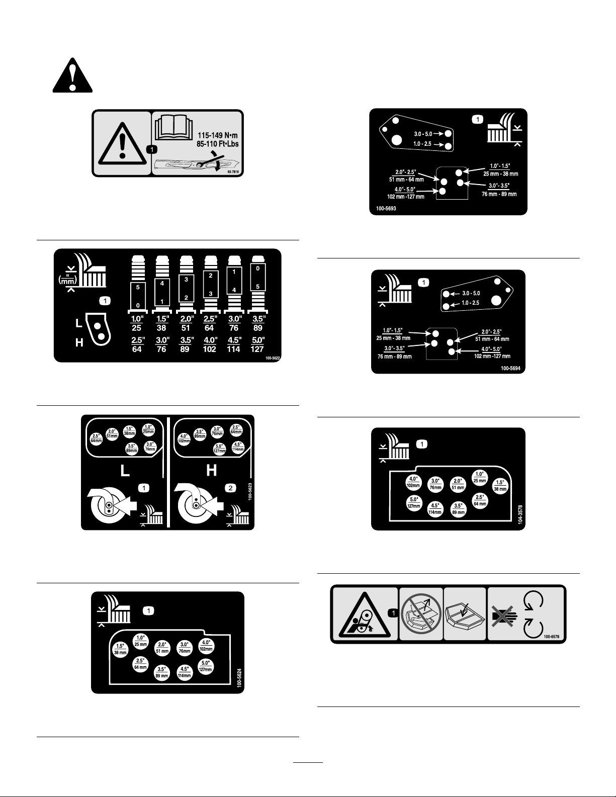
SafetyandInstructionalDecals
Safetydecalsandinstructionsareeasilyvisibletotheoperatorandarelocatednearanyareaof
potentialdanger.Replaceanydecalthatisdamagedorlost.
93-7818
1.Warning—readtheOperator’sManualforinstructionson
torquingthebladebolt/nutto115to149N•m(85to110
ft-lb).
100-5693
1.Heightofcutadjustment
1.Heightofcutadjustment
1.Lowheightofcut
adjustment
1.Heightofcutadjustment
100-5622
100-5623
2.Highheightofcut
100-5624
100-5694
1.Heightofcutadjustment
104-3578
1.Heightofcutadjustment
adjustment
100-6578
1.Entanglementhazard,belt—donotoperatethemachine
withtheshieldsorguardsremoved;alwayskeepthe
shieldsandguardsinplace;stayawayfrommovingparts.
8
Page 9
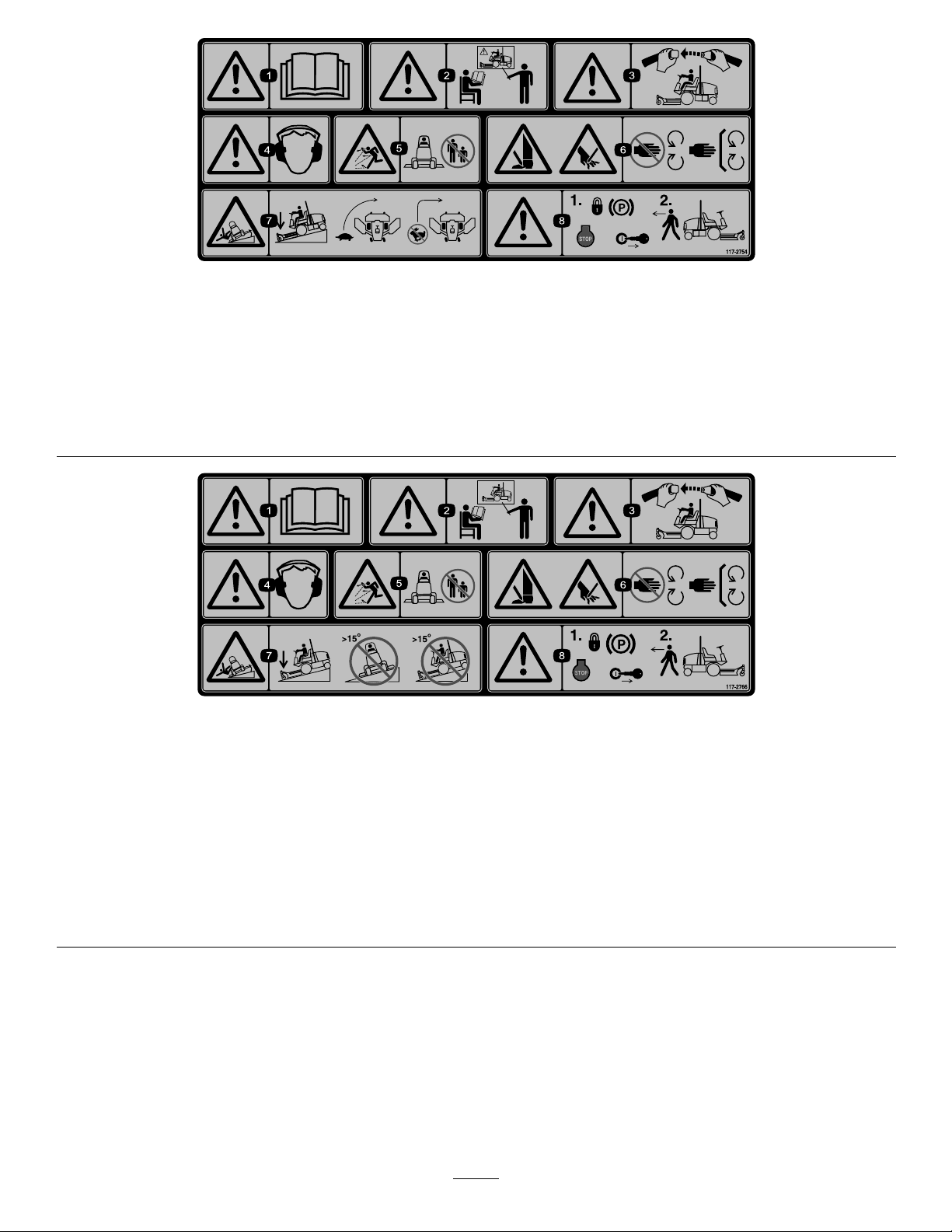
117–2754
1.Warning—readtheOperator’sManual.
2.Warning—donotoperatethismachineunlessyouaretrained.
3.Warning—weartheseatbeltwhenseatedintheoperator’sposition.
4.Warning—wearhearingprotection.
5.Thrownobjecthazard—keepbystandersasafedistancefromthemachine.
6.Cuttinghazardofhandorfoot—stayawayfrommovingparts;keepallguardsinplace.
7.Tippinghazard—lowerthecuttingunitwhendrivingdownslopes;slowmachinebeforeturning,donotturnathighspeeds
8.Warning—locktheparkingbrake,stoptheengineandremovetheignitionkeybeforeleavingthemachine.
117–2766
(Afxoverpartno.117–2754forCE*)
*ThissafetydecalincludesaslopewarningrequiredonthemachineforcompliancetotheEuropeanLawnMowerSafetyStandardEN836:1997.Theconservativemaximum
slopeanglesindicatedforoperationofthismachineareprescribedbyandrequiredbythisstandard.
1.Warning—readtheOperator’sManual.
2.Warning—donotoperatethismachineunlessyouaretrained.
3.Warning—weartheseatbeltwhenseatedintheoperator’sposition.
4.Warning—wearhearingprotection.
5.Thrownobjecthazard—keepbystandersasafedistancefromthemachine.
6.Cuttinghazardofhandorfoot—stayawayfrommovingparts;keepallguardsinplace.
7.Tippinghazard—lowerthecuttingunitwhendrivingdownslopes;donotoperatemachineonslopesgreaterthan15degrees.
8.Warning—locktheparkingbrake,stoptheengineandremovetheignitionkeybeforeleavingthemachine.
9
Page 10
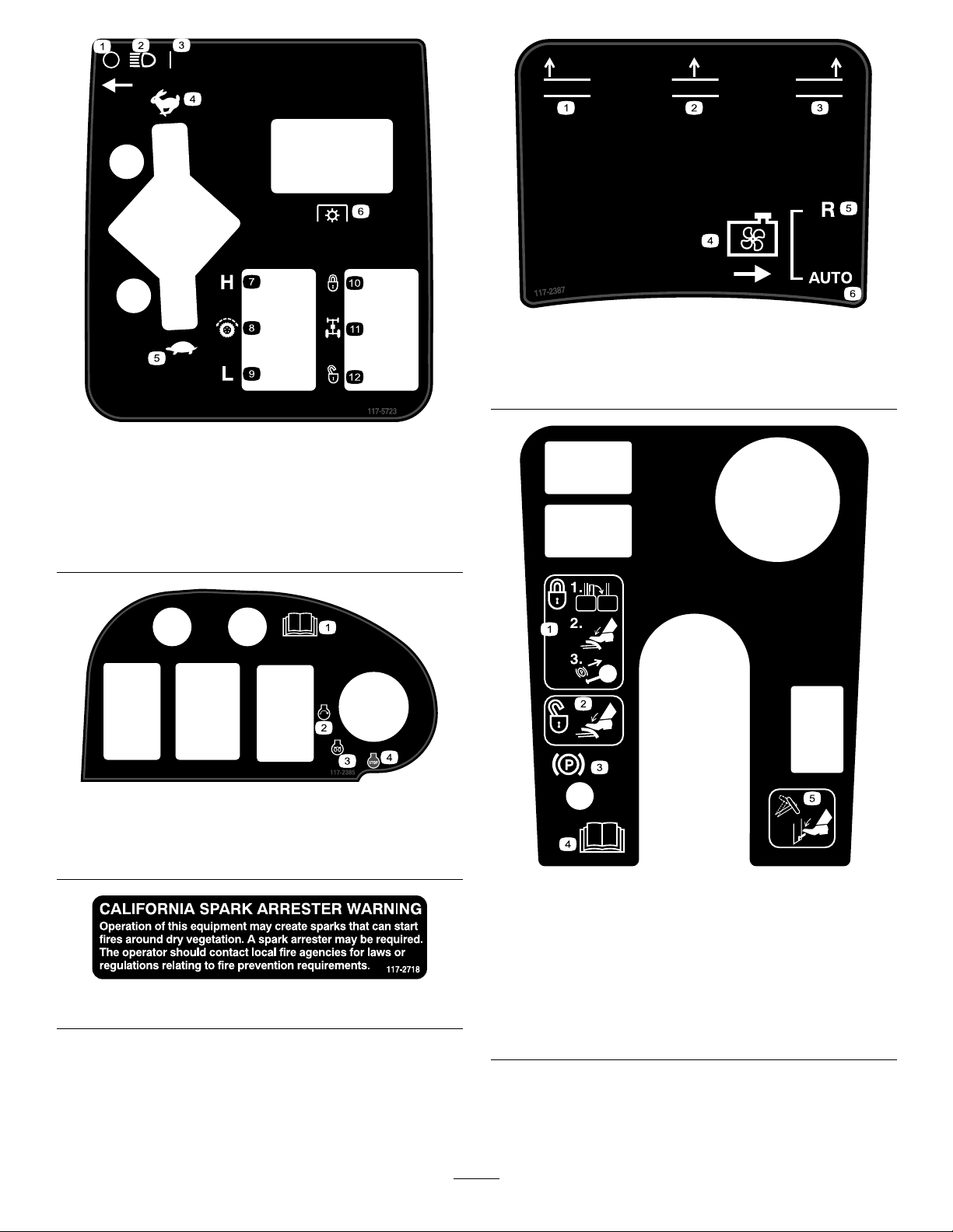
117-5723
1.Off
2.Headlights8.Tractioncontrol
3.On
4.Fast10.Locked
5.Slow
6.PowerTake-off(PTO)
7.High
9.Low
11.Flowdivider
12.Unlocked
117–2387
1.Raiseleftdeck4.Coolingfan
2.Raisecenterdeck5.Reverse
3.Raiserightdeck6.Automatic
1.ReadtheOperators
Manual.
2.Engine—start4.Engine—stop
117–2385
3.Engine—preheat
119-0067
1.Tolocktheparkingbrake,
latchthepedalstogether,
applythebrakepedals,
andpullupontheknob.
2.Tounlocktheparking
117–2718
brake,steponthebrake
pedals.
3.Parkingbrakelock
indicator
4.ReadtheOperator’s
Manual.
5.Pressdownontheleverto
tiltthesteeringwheel.
10
Page 11
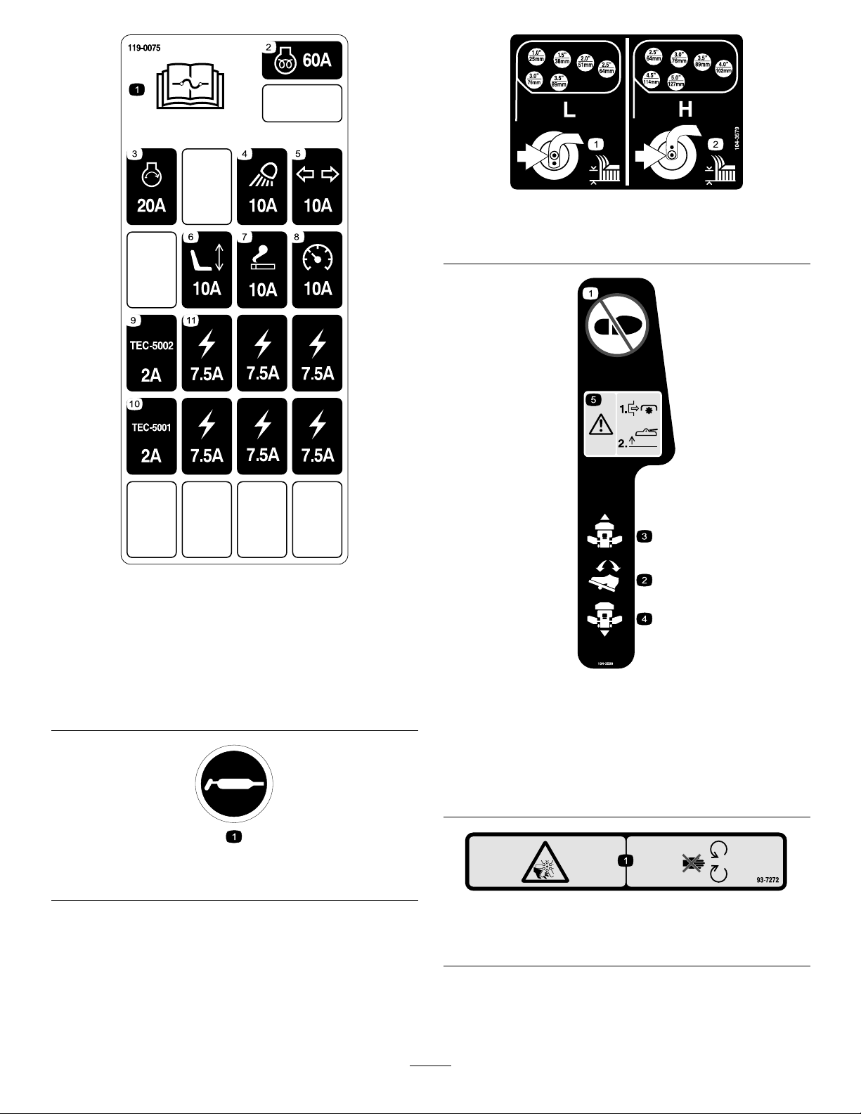
119-0075
1.ReadtheOperator’s
Manualforfuse
information.
2.Enginepreheat—60Afuse8.Instuments—10Afuse
3.Engine,start—20Afuse9.Controlmodule—2Afuse
4.Headlights—10Afuse10.Controlmodule—2Afuse
5.Signallights—10Afuse11.Powerpoint—7.5Afuse
6.PowerSeat—10Afuse
7.Powerpoint—10Afuse
104-3579
1.Lowheightofcut
adjustment
2.Highheightofcut
adjustment
104-3599
1.Donotstephere.
2.Tractionpedal
3.Traction—forward
4.Traction—reverse
5.Danger—shutoffPTOpriortoraisingthecuttingunits;do
notoperatethecuttingunitswhentheyareintheraised
position.
58-6520
1.Grease
93-7272
1.Cutting/dismembermenthazard;fan—stayawayfrom
movingparts.
11
Page 12
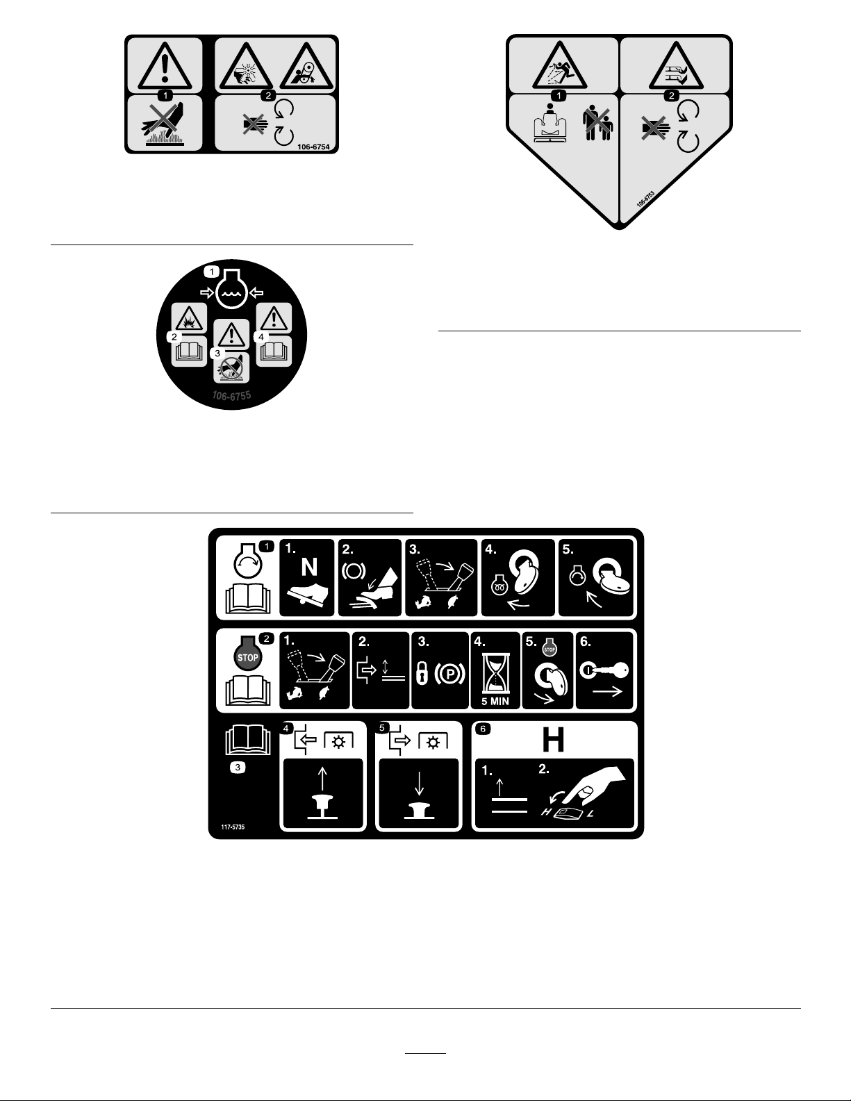
106-6754
1.Warning—donottouchthehotsurface.
2.Cutting/dismembermenthazard,fanandentanglement
hazard,belt—stayawayfrommovingparts.
106-6755
1.Enginecoolantunder
pressure.
2.Explosionhazard—read
theOperator’sManual.
106-6753
1.Thrownobjecthazard—keepbystandersasafedistance
fromthemachine.
2.Cutting/dismembermenthazardofhandorfoot,mower
blade—stayawayfrommovingparts.
3.Warning—donottouch
thehotsurface.
4.Warning—readthe
Operator’sManual.
117-5735
1.ReadtheOperatorsManual;tostarttheengine,movethetractionpedaltoNeutral,applythebrake,movethethrottleswitchto
slow,turntheignitionkeytoPreheat.WhentheWaittoStartAdvisoryclearsontheInfoCenterthenturntheignitionkeytoStart.
2.ReadtheOperatorsManual;tostoptheengine,movethethrottlelevertoslow,disengagethePTO,settheparkingbrake,wait5
minutes,turntheignitionkeytoStop,andremovethekey;readtheOperatorsManual.
3.ReadtheOperatorsManual.
4.ToengagethePTO,pulluponthePTOswitch.
5.TodisengagethePTO,pushdownonthePTOswitch.
6.Toswitchthetransmissiontohighspeed,fullyraisetheattachmentsandswitchthespeedcontroltoHigh.
12
Page 13
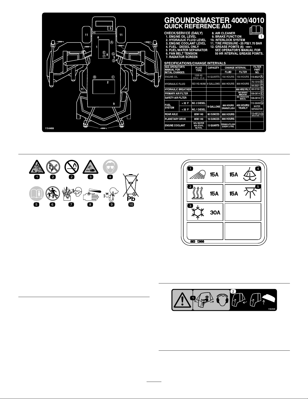
1.ReadtheOperator’sManual.
BatterySymbols
Someorallofthesesymbolsareonyourbattery
1.Explosionhazard
2.Nore,opename,or
smoking.
3.Causticliquid/chemical
burnhazard
4.Weareyeprotection9.Flusheyesimmediately
5.ReadtheOperator’s
Manual.
6.Keepbystandersasafe
7.Weareyeprotection;
8.Batteryacidcancause
10.Containslead;donot
distancefromthebattery .
explosivegasescan
causeblindnessandother
injuries
blindnessorsevereburns.
withwaterandgetmedical
helpfast.
discard.
115-8456
117–2787
1.Headlights,15Afuse
2.Heater,15Afuse5.Domelight,15Afuse
3.Airconditioning,30Afuse
4.Windshieldwipers,15A
fuse
119–0124
(Model30446only)
1.Warning—whenthecabwindowsareopenwearhearing
protection.
2.Closetherearwindowbeforeattemptingtoopenthehood.
13
Page 14
Setup
LooseParts
Usethechartbelowtoverifythatallpartshavebeenshipped.
ProcedureDescription
1
2
Nopartsrequired
WarningDecal1
MediaandAdditionalParts
Description
Operator’sManual
EngineOperator’sManual
PartsCatalog
OperatorTrainingMaterials
Pre-deliveryInspectionSheet
Declarationofconformity
Note:Determinetheleftandrightsidesofthemachine
fromthenormaloperatingposition.
Qty.
Qty.
–
1
1
1
1
1
1
Reviewbeforeoperatingmachine
Usetoreferenceengineinformation
Usetoreferencepartnumbers
Reviewbeforeoperatingmachine
Greasethemachine.
Usedonlyonmachinesrequiring
EuropeanCEcompliance.
Use
Use
2
1
GreasingtheMachine
NoPartsRequired
Procedure
Beforethemachineisoperated,itmustbegreased
toensureproperlubricatingcharacteristics;referto
GreasingtheBearingsandBushingsinLubrication.
Failuretoproperlygreasethemachinewillresultin
prematurefailureofcriticalparts.
ReplacingtheWarningDecal
Partsneededforthisprocedure:
1WarningDecal
Procedure
OnmachinesrequiringEuropeanCEcompliance,
replacethewarningdecal,partno.117–2754withthe
warningdecalpartno.117–2766.
14
Page 15

ProductOverview
PedalLockingLatch
ThepedallockinglatchFigure2connectsthepedals
Controls
togethertoengagetheparkingbrake.
Note:Determinetheleftandrightsidesofthemachine
fromthenormaloperatingposition.
Thismachineproducessoundlevelsinexcess
of85dBAattheoperatorsearandcancause
hearinglossthroughextendedperiodsof
exposure.
Wearhearingprotectionwhenoperatingthis
machine.
TractionPedal
Tostop,reduceyourfootpressureonthetractionpedal
andallowittoreturntothecenterposition(Figure2).
TiltSteeringLever
PresstheleverFigure2downtotiltthesteeringwheel
tothedesiredposition.Thenreleasethelevertolock
theadjustment.
ParkingBrakeLatch
Aknobontheleftsideoftheconsoleactuatesthe
parkingbrakelock(Figure2).Toengagetheparking
brake,connectthepedalswiththelockinglatch,push
downonbothpedals,andpulltheparkingbrakelatch
out.Toreleasetheparkingbrake,pressbothpedalsuntil
theparkingbrakelatchretracts.
FuelGauge
Thefuelgauge(Figure2)indicatestheleveloffuelin
thetank.
SpeedLimiter
Ifdesired,thescrewcanbeadjusted(Figure3)tolimit
theamountthetractionpedalcanbedepressedinthe
forwarddirectiontolimitthemowingspeed.
Figure2
1.Brakepedals6.Fuelgauge
2.Pedallockinglatch
3.Spaceforoptional
accessory
4.Spaceforoptional
accessory
5.Parkingbrakelatch
7.Spaceforoptional
accessory
8.Tiltsteeringlever
9.Tractionpedal
BrakePedals
TwofootpedalsFigure2operateindividualwheelbrakes
forturningassistance,parking,andtoaidinobtaining
bettersidehilltraction.Alatchconnectsthepedalsfor
parkingbrakeoperationandtransport.
Figure3
1.Speedlimiter
2.Jamnuts
Important:Wheninthemowposition,thespeed
limiterscrewmuststopthetractionpedalbeforethe
pumpreachesfullstrokeordamagetothepump
mayoccur.
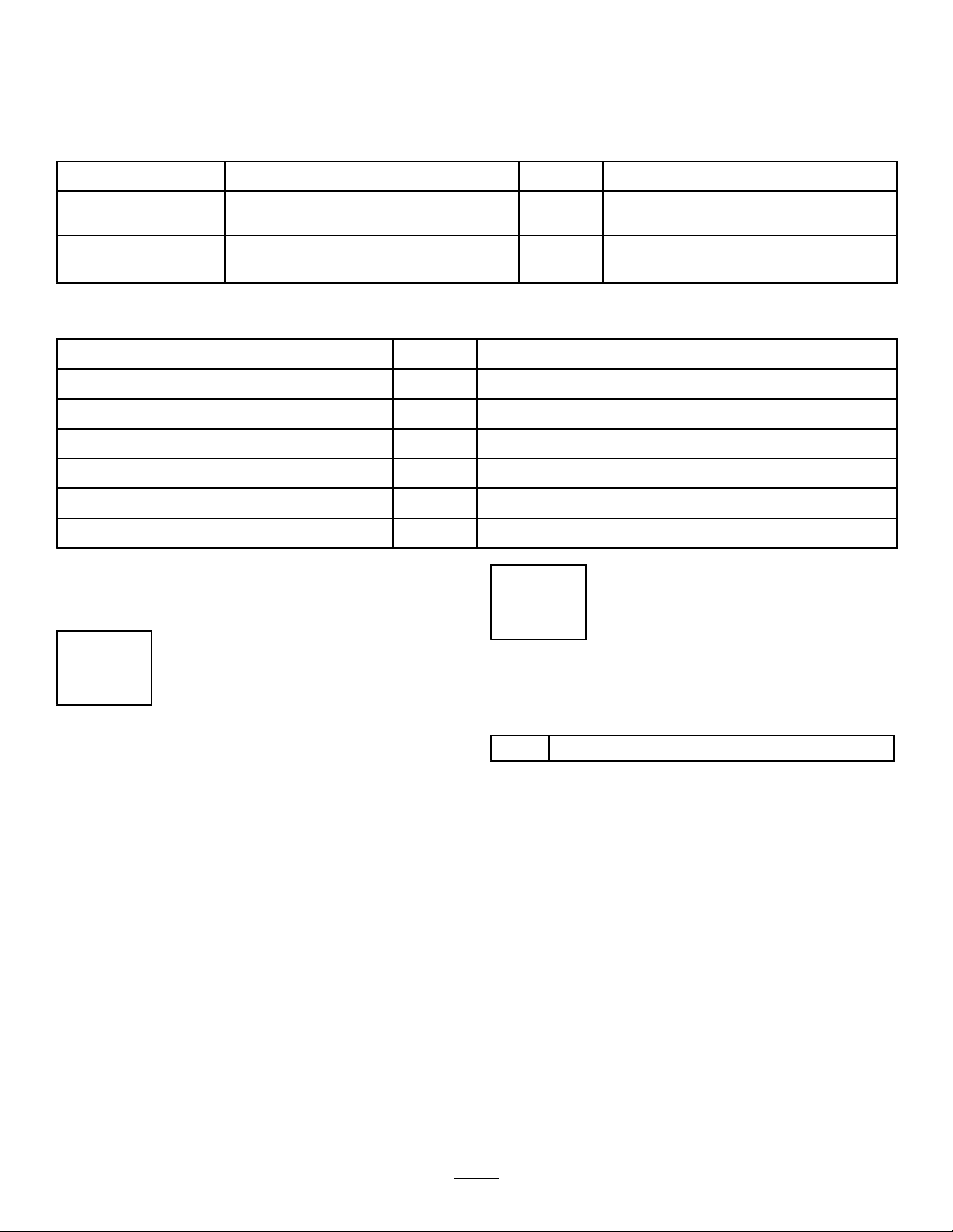
DiagnosticLight
Thediagnosticlight(Figure4)willilluminateshoulda
systemfaultberecognized.
15
Page 16
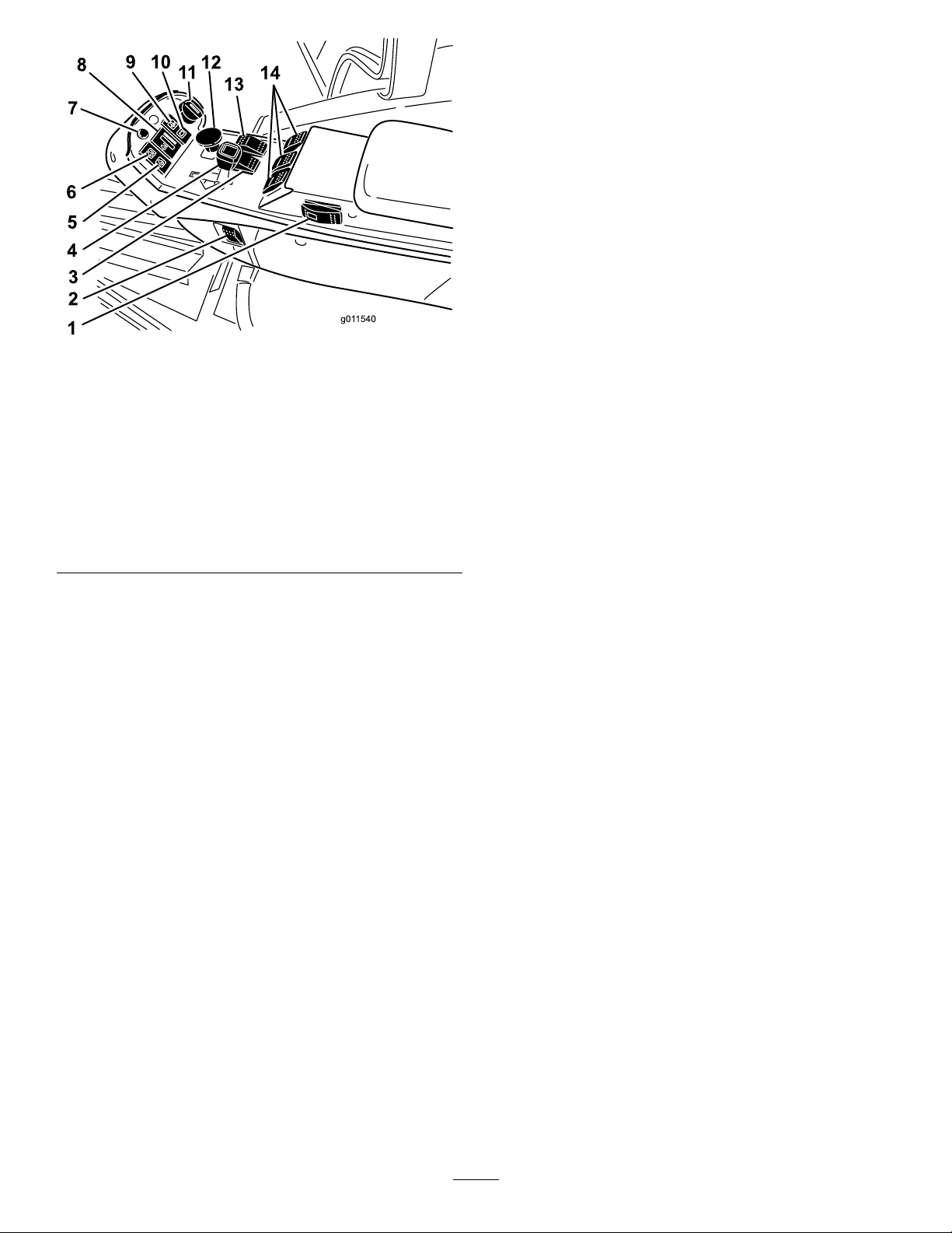
Figure4
1.Cruisecontrol(optional)
2.Lightswitch9.Engineoilpressure
3.Hi-Lospeedcontrol
4.Throttlecontrol11.Keyswitch
5.Glowplugindicatorlight12.PTOswitch
6.Enginecoolant
temperaturewarning
light
7.Diagnosticlight
8.Enginecoolant
temperaturegauge
warninglight
10.Chargeindicator
13.Flowdividerswitch
14.Liftswitches
FlowDividerSwitch
Whenoperatinginmow(low)speed,pressandhold
owdividerswitch(Figure4)toenhancetractiondrive
performanceincompromisedoperatingconditions.
Hi-LoSpeedControl
Theswitch(Figure4)allowsthespeedrangetoincrease
fortransportofthemachine.Cuttingdeckswillnot
operateinhighrange.Also,thedeckscannotbelowered
fromthetransportpositionwhentheswitchisinthe
highrange.IftheswitchismovedfromLOtoHIwith
thecuttingdecksdownand/orPTOonand/orcruise
controlengaged,thetransmissionwillnotchangetoHI.
Forthechangetobeaccomplished,theswitchmustbe
movedtoLOandalltherequirementssatised.
LiftSwitches
Theliftswitches(Figure4)raiseandlowerthecutting
units.Presstheswitchesforwardtolowerthecutting
unitsandbackwardtoraisethecuttingunits.When
startingthemachine,withthecuttingunitsinthedown
position,presstheliftswitchdowntoallowthecutting
unitstooatandmow .
EngineCoolantTemperatureGauge
Duringnormaloperatingconditionsthegauge(Figure4)
shouldbeinthegreenrange.Checkthecoolingsystem
ifthegaugegoestotheyelloworredrange.
EngineOilPressureWarningLight
Thelight(Figure4)illuminateswhentheengineoil
pressureisdangerouslylow.
ChargeIndicator
Thechargeindicator(Figure4)illuminateswhenthe
systemchargingcircuitmalfunctions.
KeySwitch
Thekeyswitch(Figure4)hasthreepositions:Off,
On/Preheat,andStart.
PTOSwitch
ThePTOswitch(Figure4)hastwopositions:Out
(start)andIn(stop).PullthePTObuttonouttoengage
thecuttingunitblades.Pushinthebuttontodisengage
thecuttingunitblades.
Note:ThedeckswillnotlowerwhileintheHIspeed
rangeandtheywillnotraiseorloweriftheoperatoris
outoftheseatwhentheengineisrunning.
ThrottleControl
Movethecontrol(Figure4)forwardtoincreasethe
enginespeedandrearwardtodecreasethespeed.
LightSwitch
Presstheloweredgeoftheswitch(Figure4)toturnon
thelights.Presstheupperedgeoftheswitchtoturn
offthelights.
GlowPlugIndicatorLight
Whenlit,theglowplugindicatorlight(Figure4)
indicatesthattheglowplugsareon.
EngineCoolantTemperatureWarning
Light
Thelight(Figure4)illuminatesandthecuttingunitsshut
down(PTOdisengages)iftheenginereachesanunsafe
operatingtemperature.Ifthetemperaturecontinuesto
risetheenginewillshutdown.
16
Page 17
EngineCoolingFanSwitch
G011547
1
2
3
AirConditioningSwitch
Themachineisequippedwithahydraulicallydriven
autoreversingenginecoolingfan.Thefanswitch
(Figure5)hastwopositionsR(manualreverse)and
Auto(normal).RefertoEngineCoolingFanOperation
intheOperationSectionofmanual.
Figure5
1.Powerpoint3.Hourmeter
2.Enginecoolingfanswitch
Pressfrontofswitchtoactivatetheairconditioning
(Figure6)andrearofswitchtoturnofftheair
conditioning.
FanControl
Rotatethefancontrolknobtoregulatethespeedofthe
fan(Figure6).
TemperatureControl
Rotatethetemperaturecontrolknobtoregulatetheair
temperatureinthecab(Figure6).
HourMeter
Thehourmeter(Figure5)showsthetotalhoursthatthe
machinehasbeenoperated.
PowerPoint
Thepowerpoint(Figure5)isusedtopoweroptional
electricalaccessories.
AudibleAlarm
Towarnbystanders,analarmwillsoundifthecutting
decksareloweredwiththeengineoff.Thealarmwill
quitsoundingoncethedecklowerswitchisreleased.
Also,thealarmwillsoundiftheenginecoolant
temperaturereachesaset-pointthatcutsoutthePTO
operation.Thealarmwillcontinuetosounduntilthe
coolanttemperaturedropsbelowtheset-pointorthe
PTOswitchisdisengaged.
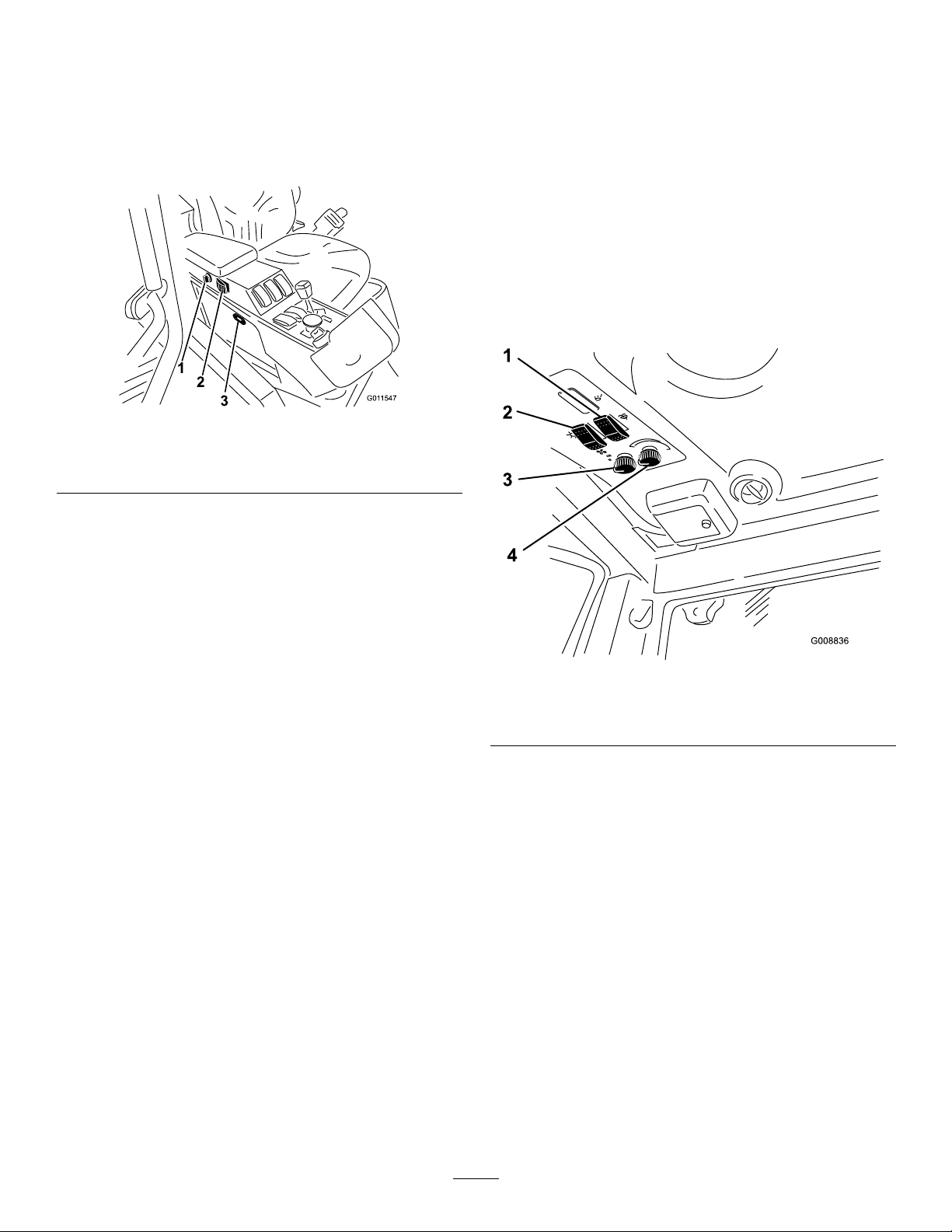
CabControls
Figure6
1.Windshieldwiperswitch3.Fancontrol
2.Airconditioningswitch4.Temperaturecontrol
WindShieldLatch
Liftuponlatchestoopenthewindshield(Figure7).
Pressinonlatchtolockwindshieldinopenposition.
Pulloutanddownonlatchtocloseandsecurewind
shield.
Model30446only
WindShieldWiperSwitch
Pressfrontofswitchtoactivatethewindshieldwipers
(Figure6)andrearofswitchtoturnoffthewipers.
17
Page 18
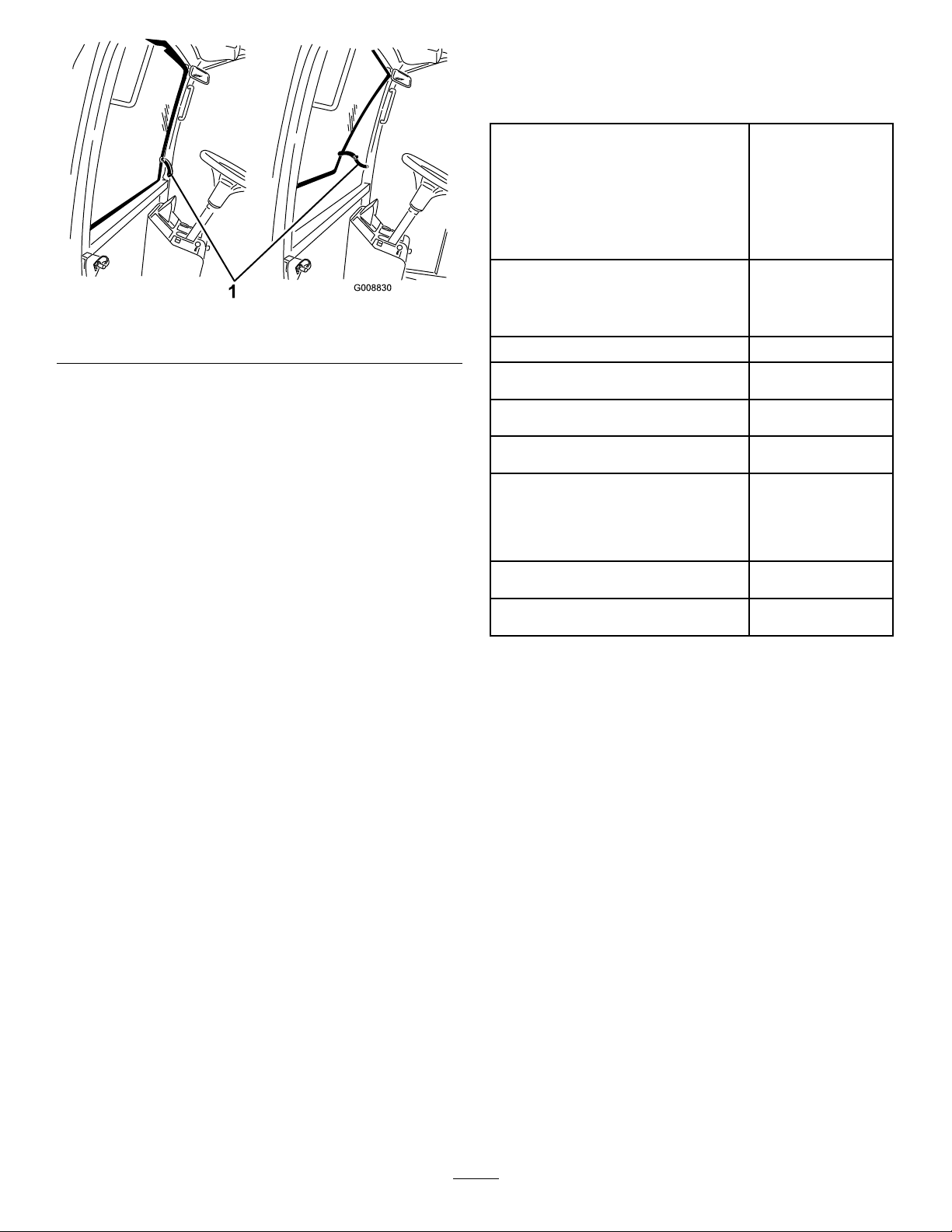
1.Windshieldlatch
Figure7
Specications
Note:Specicationsanddesignaresubjecttochange
withoutnotice.
Widthofcut
overall
frontcuttingunit62inch(157cm)
sidecuttingunit
frontandonesidecuttingunit97inch(246cm)
Overallwidth
cuttingunitsdown
cuttingunitsup(transports)72inch(183cm)
Overalllength135inch(342cm)
Height
132inch(335cm)
42inch(107cm)
136inch(345cm)
55inch(140cm)
RearWindowLatch
Liftuponlatchestoopentherearwindow .Pressinon
latchtolockwindowinopenposition.Pulloutand
downonlatchtocloseandsecurewindow(Figure7).
Important:Therearwindowmustbeclosedbefore
openingthehoodordamagemayoccur.
HeightwithROPS
Heightwithcab
Groundclearance6-1/2inch(17cm)
Wheeltread(tocenteroftire)
front45inch(1 14cm)
rear
Wheelbase
(NetWeight)
(NetWeightwithcab)
81inch(206cm)
91inch(231cm)
47inch(119cm)
55-1/2in(141cm)
4166lb(1890kg)
4595lb(2084kg)
Attachments/Accessories
AselectionofToroapprovedattachmentsand
accessoriesareavailableforusewiththemachineto
enhanceandexpanditscapabilities.Contactyour
AuthorizedServiceDealerorDistributororgoto
www.Toro.comforalistofallapprovedattachments
andaccessories.
18
Page 19
Operation
Note:Determinetheleftandrightsidesofthe
machinefromthenormaloperatingposition.
BeforeOperating
Ifyouleavethekeyintheignitionswitch,
someonecouldaccidentlystarttheengineand
seriouslyinjureyouorotherbystanders.
Removethekeyfromtheignitionbeforeyoudo
anymaintenance.
CheckingtheEngineOil
ServiceInterval:Beforeeachuseordaily
Theengineisshippedwithoilinthecrankcase;
however,theoillevelmustbecheckedbeforeandafter
theengineisrststarted.
Thecrankcasecapacityis10qt(9.5l)withthelter.
Usehigh-qualityengineoilthatmeetsthefollowing
specications:
•APIClassicationLevelRequired:CH-4,CI-4or
higher.
•Preferredoil:SAE15W -40(above0°F)
•Alternateoil:SAE10W -30or5W-30(all
temperatures)
ToroPremiumEngineOilisavailablefromyour
distributorineither15W-40or10W-30viscosity.See
thepartscatalogforpartnumbers.
Note:Thebesttimetochecktheengineoiliswhenthe
engineiscoolbeforeithasbeenstartedfortheday.Ifit
hasalreadybeenrun,allowtheoiltodrainbackdown
tothesumpforatleast10minutesbeforechecking.
Iftheoillevelisatorbelowthe“add”markonthe
dipstick,addoiltobringtheoilleveltothe“full”mark.
DONOTOVERFILL.Iftheoillevelisbetweenthe
“full”and“add”marks,noadditionaloilisrequired.
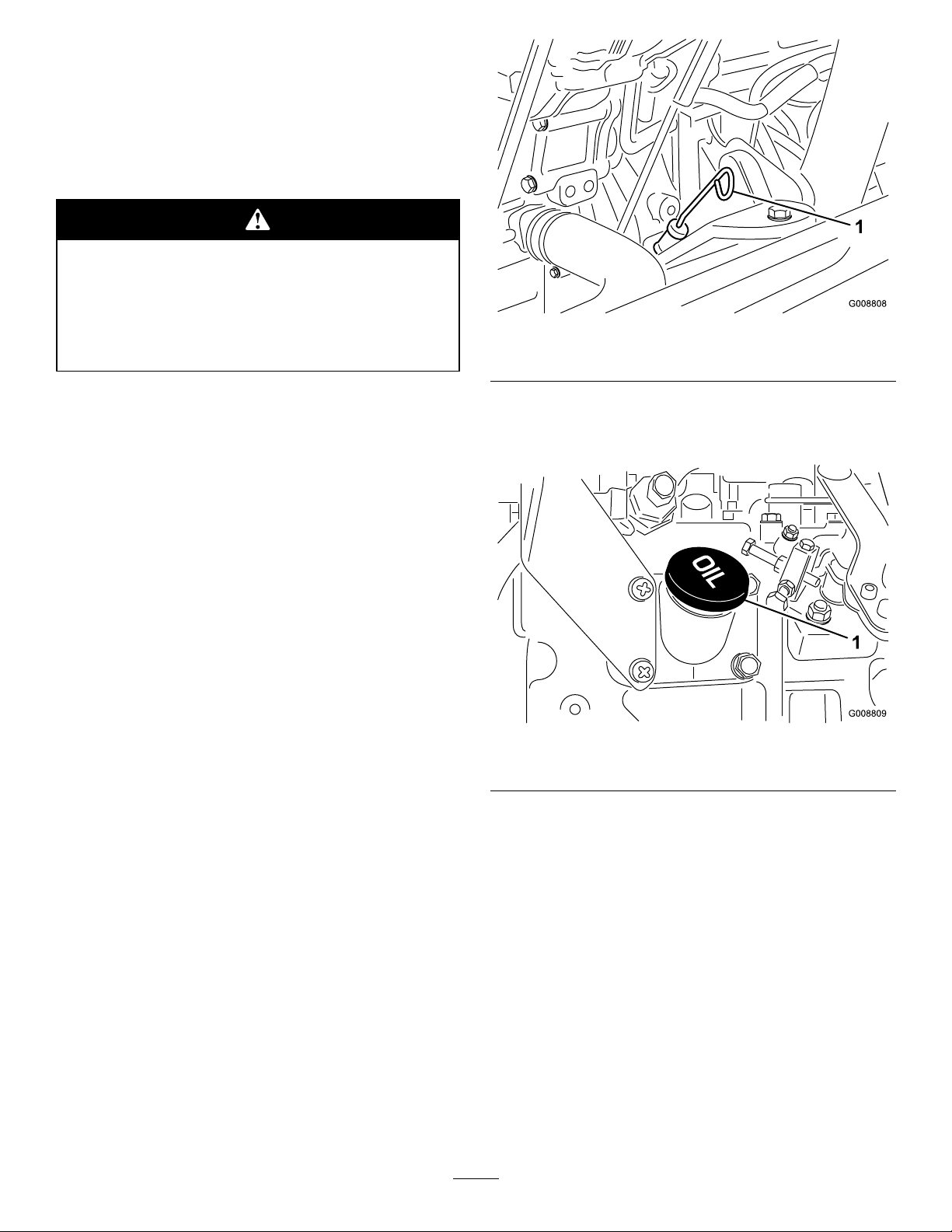
1.Parkthemachineonalevelsurface.Unlockthe
enginecoverlatches.
Figure8
1.Dipstick
4.IftheoilisbelowtheFullmark,removethellcap
(Figure9)andaddoiluntilthelevelreachestheFull
mark.Donotoverll.
Figure9
1.Oilllcap
5.Installtheoilllcapanddipstick.
6.Closetheenginecoverandsecureitwiththelatches.
CheckingtheCoolingSystem
ServiceInterval:Beforeeachuseordaily
Checklevelofcoolantatthebeginningofeachday.
Capacityofsystemis13qts.(12.3l).
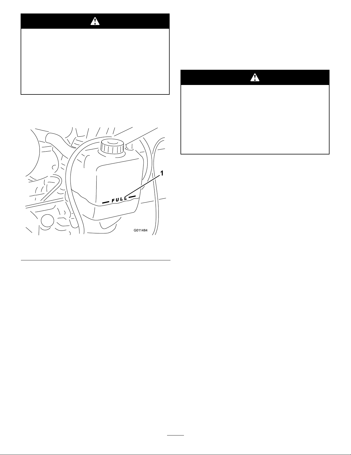
1.Carefullyremovetheradiatorcapandexpansion
tankcap(Figure10).
2.Opentheenginecover.
3.Removethedipstick,wipeitclean,installthe
dipstickintothetube,andpullitoutagain.Theoil
levelshouldbeuptotheFullmark(Figure8).
19
Page 20
Iftheenginehasbeenrunning,thepressurized,
hotcoolantcanescapeandcauseburns.
•Donotopentheradiatorcapwhenthe
engineisrunning.
•Usearagwhenopeningtheradiatorcap,
andopenthecapslowlytoallowsteamto
escape.
2.Checkthecoolantlevelintheradiator.Theradiator
shouldbelledtothetopofthellerneckandthe
expansiontanklledtotheFullmark.
Useofsummergradefuelabove20°F(-7°C)will
contributetowardlongerfuelpumplifeandincreased
powercomparedtowintergradefuel.
Important:Donotusekeroseneorgasoline
insteadofdieselfuel.Failuretoobservethis
cautionwilldamagetheengine.
Fuelisharmfulorfatalifswallowed.Long-term
exposuretovaporscancauseseriousinjuryand
illness.
•Avoidprolongedbreathingofvapors.
•Keepfaceawayfromnozzleandgastankor
conditioneropening.
•Keepfuelawayfromeyesandskin.
BiodieselReady
Thismachinecanalsouseabiodieselblendedfuel
ofuptoB20(20%biodiesel,80%petrodiesel).The
petrodieselportionshouldbeloworultralowsulfur.
Observethefollowingprecautions:
Figure10
1.Expansiontank
3.Ifthecoolantislow ,adda50/50mixtureofwater
andethyleneglycolanti-freeze.Donotusewater
onlyoralcohol/methanolbasecoolants.
4.Installtheradiatorcapandexpansiontankcap.
AddingFuel
Useonlyclean,freshdieselfuelorbiodieselfuelswith
low(<500ppm)orultralow(<15ppm)sulfurcontent.
Theminimumcetaneratingshouldbe40.Purchase
fuelinquantitiesthatcanbeusedwithin180daysto
ensurefuelfreshness.
Fueltankcapacity:19USgallons(72l)
•Thebiodieselportionofthefuelmustmeet
specicationASTMD6751orEN14214.
•TheblendedfuelcompositionshouldmeetASTM
D975orEN590.
•Paintedsurfacesmaybedamagedbybiodiesel
blends.
•UseB5(biodieselcontentof5%)orlesserblends
incoldweather.
•Monitorseals,hoses,gasketsincontactwithfuelas
theymaybedegradedovertime.
•Fuellterpluggingmaybeexpectedforatimeafter
convertingtobiodieselblends.
•Contactyourdistributorifyouwishformore
informationonbiodiesel.
Usesummergradedieselfuel(No.2-D)attemperatures
above20°F(-7°C)andwintergrade(No.1-Dor
No.1-D/2-Dblend)belowthattemperature.Useof
wintergradefuelatlowertemperaturesprovideslower
ashpointandcoldowcharacteristicswhichwillease
startingandreducefuellterplugging.
20
Page 21

Incertainconditions,fuelisextremely
ammableandhighlyexplosive.Areor
explosionfromfuelcanburnyouandothers
andcandamageproperty.
•Fillthefueltankoutdoors,inanopenarea,
whentheengineiscold.Wipeupanyfuel
thatspills.
•Neverllthefueltankinsideanenclosed
trailer.
•Neversmokewhenhandlingfuel,andstay
awayfromanopenameorwherefuel
fumesmaybeignitedbyaspark.
•Storefuelinanapprovedcontainerandkeep
itoutofthereachofchildren.Neverbuy
morethana30-daysupplyoffuel.
•Donotoperatewithoutentireexhaust
systeminplaceandinproperworking
condition.
1.Parkthemachineonalevelsurface.
2.Usingacleanrag,cleanareaaroundfueltankcap.
3.Removecapfromthefueltank(Figure11).
Figure11
1.Fueltankcap
4.Fillthetankuntilthelevelistothebottomofthe
llerneckwithdieselfuel.
Incertainconditionsduringfueling,static
electricitycanbereleasedcausingaspark
whichcanignitethefuelvapors.Areor
explosionfromfuelcanburnyouandothers
andcandamageproperty.
•Alwaysplacefuelcontainersontheground
awayfromyourvehiclebeforelling.
•Donotllfuelcontainersinsideavehicle
oronatruckortrailerbedbecauseinterior
carpetsorplastictruckbedlinersmay
insulatethecontainerandslowthelossof
anystaticcharge.
•Whenpractical,removeequipmentfromthe
truckortrailerandrefueltheequipment
withitswheelsontheground.
•Ifthisisnotpossible,thenrefuelsuch
equipmentonatruckortrailerfroma
portablecontainer,ratherthanfromafuel
dispensernozzle.
•Ifafueldispensernozzlemustbeused,keep
thenozzleincontactwiththerimofthefuel
tankorcontaineropeningatalltimesuntil
fuelingiscomplete.
5.Installfueltankcaptightlyafterllingtank.
Note:Ifpossible,llthefueltankaftereachuse.
Thiswillminimizepossiblebuildupofcondensation
insidethefueltank.
CheckingtheHydraulicFluid
ServiceInterval:Beforeeachuseordaily
Themachinesreservoirislledatthefactorywith
approximately8U.S.gallons(30.2l)ofhighquality
hydraulicuid.Checkthelevelofthehydraulic
uidbeforetheengineisrststartedanddaily
thereafter.Therecommendedreplacementuidis:
ToroPremiumAllSeasonHydraulicFluid
(Availablein5gallonpailsor55gallondrums.Seeparts
catalogorTorodistributorforpartnumbers.)
Alternateuids:IftheT orouidisnotavailable,other
uidsmaybeusedprovidedtheymeetallthefollowing
materialpropertiesandindustryspecications.Wedo
notrecommendtheuseofsyntheticuid.Consult
withyourlubricantdistributortoidentifyasatisfactory
product.
Note:Torowillnotassumeresponsibilityfordamage
causedbyimpropersubstitutions,souseonlyproducts
fromreputablemanufacturerswhowillstandbehind
theirrecommendation.
HighViscosityIndex/LowPourPointAnti-wear
HydraulicFluid,ISOVG46
21
Page 22

HighViscosityIndex/LowPourPointAnti-wear
HydraulicFluid,ISOVG46(cont'd.)
MaterialProperties:
St@40°C44to48 Viscosity,ASTMD445
St@100°C7.9to8.5
ViscosityIndexASTMD2270
PourPoint,ASTMD97-34°Fto-49°F
IndustrySpecications:VickersI-286-S(Quality
Level),VickersM-2950-S
(QualityLevel),Denison
140to160
Note:Manyhydraulicuidsarealmostcolorless,
makingitdifculttospotleaks.Areddyeadditivefor
thehydraulicsystemoilisavailablein2/3oz(20ml)
bottles.Onebottleissufcientfor4-6gallons(15-22
1)ofhydraulicoil.Orderpartno.44-2500fromyour
authorizedTorodistributor.
1.Positionthemachineonalevelsurface,lowerthe
cuttingunits,stoptheengine,andremovethekey.
2.Unlatchtheseat,raiseit,andengagetheproprod.
3.Cleantheareaaroundthellerneckandcapofthe
hydraulictank(Figure12).Removethecapfrom
thellerneck.
CheckingthePlanetaryGearDriveOil
ServiceInterval:Every400hours
Checktheoillevelafterevery400hoursofoperation
orifexternalleakageisnoted.UsehighqualitySAE
85W-140gearlubeasareplacement.
Thecapacityofthesystemisapproximately16oz(0.5
l).
1.Withthemachineonalevelsurface,positionthe
wheelsothatthecheck/drainplug(Figure13)isat
HF-0
eitherthe3or9o’clockposition.
Figure13
1.Check/drainplug
2.Addgearoiltotheholeintheplanetary,ifnecessary,
tobringtheoiluptotheproperlevel.Installthe
plug.
Figure12
1.Hydraulictankcap
4.Removethedipstickfromthellerneckandwipe
itwithacleanrag.Insertthedipstickintotheller
neck;thenremoveitandchecktheuidlevel.The
uidlevelshouldbebetweenthetwomarksonthe
dipstick.
5.Ifthelevelislow ,addtheappropriateuidtoraise
theleveltotheuppermark.
3.Repeattheprocedureontheoppositegearassembly .
CheckingtheRearAxleLubricant
ServiceInterval:Every400hours
TherearaxleislledwithSAE85W-140gearlube.
Checktheoillevelbeforetheengineisrststartedand
every400hoursthereafter.Thecapacityis80oz(2.4l).
Visuallyinspectforleaksdaily.
1.Positionthemachineonalevelsurface.
2.Removeacheckplugfromoneendoftheaxle
(Figure14)andmakesurethatthelubricantisupto
thebottomofthehole.Ifthelevelislow,remove
thellplug(Figure14)andaddenoughlubricantto
bringtheleveluptothebottomofthecheckplug
holes.
6.Installthedipstickandcapontothellerneck.
22
Page 23

correctairpressureinthefrontandreartiresis25-30
psi(172-207kPa).
Important:Maintainevenpressureinalltiresto
ensureagoodquality-of-cutandpropermachine
performance.
Do not under -inate.
CheckingtheTorqueoftheWheelNuts
orBolts
Figure14
1.Checkplug
2.Fillplug
CheckingtheRearAxleGearBox
Lubricant
ServiceInterval:Every400hours
ThegearboxislledwithSAE85W-140gearlube.
Checktheoillevelbeforetheengineisrststartedand
every400hoursthereafter.Thecapacityis16oz(0.5l).
Visuallyinspectforleaksdaily.
1.Positionthemachineonalevelsurface.
2.Removethecheck/llplugfromtheleftsideofthe
gearbox(Figure15)andmakesurethatlubricant
isuptothebottomofthehole.Ifthelevelislow ,
addenoughlubricanttobringtheleveluptothe
bottomofthehole.
ServiceInterval:Aftertherst10hours
Every200hours
Failuretomaintainpropertorqueofthewheel
nutscouldresultinfailureorlossofwheeland
mayresultinpersonalinjury.
Torquethefrontwheelnutsandrearboltsto85
to100ft-lb(115to136N⋅ ⋅⋅m)after1-4hoursof
operationandagainafter10hoursofoperation.
Torqueevery200hoursthereafter.
AdjustingtheHeight-of-Cut
FrontCuttingUnit
Theheight-of-cutisadjustablefrom1to5inches(25
to127mm)in1/2inch(13mm)increments.Toadjust
theheight-of-cutonthefrontcuttingunit,positionthe
castorwheelaxlesintheupperorlowerholesofthe
castorforks,addorremoveanequalnumberofspacers
fromthecastorforks,andsecuretherearchaintothe
desiredhole.
Figure15
1.Gearbox2.Check/llplug
CheckingtheTirePressure
ServiceInterval:Beforeeachuseordaily
Thetiresareover-inatedforshipping.Therefore,
releasesomeoftheairtoreducethepressure.The
1.Starttheengineandraisethecuttingunitssothat
theheight-of-cutcanbechanged.Stoptheengine
andremovethekeyafterthecuttingunitisraised.
2.Positionthecastorwheelaxlesinthesameholes
inallcastorforks.Refertothefollowingchartto
determinethecorrectholesforthesetting.
23
Page 24

Figure16
1.Tensioningcap4.T opaxlemountinghole
2.Spacers5.Castorwheel
3.Shims
Note:Whenoperatingin2-1/2inch(64mm)
heightofcutorhigher,theaxleboltmustbe
installedinthelowercastorforkholetoprevent
grassbuildupbetweenthewheelandthefork.
Whenoperatinginheightofcutslowerthan2-1/2
inches(64mm)andgrassbuildupisdetected,
reversethemachinesdirectiontopullanyclippings
awayfromthewheel/forkarea.
spindleshaft.Installthetensioningcaptosecure
theassembly .
5.Removethehairpincotterandclevispinsecuring
theheight-of-cutchainstotherearofthecutting
unit(Figure18).
Figure18
1.Height-of-cutchain2.Clevispin&hairpincotter
6.Mounttheheight-of-cutchainstothedesired
height-of-cuthole(Figure19)withtheclevispin
andhairpincotter.
3.Removethetensioningcapfromthespindleshaft
(Figure16)andslidethespindleoutofthecastor
arm.Putthe2shims(1/8inch[3mm])ontothe
spindleshaftastheywereoriginallyinstalled.These
shimsarerequiredtoachievealevelacrosstheentire
widthofthecuttingunits.Slidetheappropriate
numberof1/2inchspacers(refertothechart
below)ontothespindleshafttogetthedesired
height-of-cut;thenslidethewasherontotheshaft.
Refertothefollowingcharttodeterminethe
combinationsofspacersforthesetting:
Figure17
4.Pushthecastorspindlethroughthefrontcastor
arm.Installtheshims(astheywereoriginally
installed)andtheremainingspacersontothe
Figure19
Note:Whenusing1inch(25mm),1-1/2inch(38
mm),oroccasionally2inch(51mm)height-of-cut,
movetheskidsandgagewheelstothehighest
position.
SideCuttingUnits
Toadjusttheheight-of-cutonthesidecuttingunits,add
orremoveanequalnumberofspacersfromthecastor
forks,positionthecastorwheelaxlesinthehighorlow
height-of-cutholesinthecastorforks,andsecurethe
pivotarmstotheselectedheight-of-cutbracketholes.
1.Positionthecastorwheelaxlesinthesameholes
inallofthecastorforks(Figure20andFigure22).
Refertothefollowingcharttodeterminethe
correctholeforthesetting.
2.Removethetensioningcapfromthespindleshaft
(Figure20)andslidethespindleoutofcastorarm.
24
Page 25

Putthetwoshims(1/8inch[3mm])ontospindle
shaftastheywereoriginallyinstalled.Theseshims
arerequiredtoachievealevelacrosstheentire
widthofthecuttingunits.Slidetheappropriate
numberof1/2inchspacersontothespindleshaft
togetthedesiredheight-of-cut;thenslidethe
washerontotheshaft.
Figure20
1.Tensioningcap4.T oaxlemountinghole
2.Spacers5.Castorwheel
3.Shims
7.Rotatetensionrodcounterclockwise(ngertight)
toputtensiononadjustment.
Figure22
1.Castorpivotarm3.Clevispinandhairpin
cotter
2.Axlemountingholes4.T ensionrod
Refertothefollowingcharttodeterminethe
combinationsofspacersforthesetting.
Figure21
3.Pushthecastorspindlethroughthecastorarm.
Installtheshims(asoriginallyinstalled)andthe
remainingspacersontothespindleshaft.Installthe
tensioningcaptosecuretheassembly.
4.Removethehairpincotterandclevispinsfromthe
castorpivotarms(Figure22).
5.Rotatetensionrodtoraiseorlowerpivotarm
untilholesarealignedwithselectedheight-of-cut
bracketholesinthecuttingunitframe(Figure22
andFigure23).
Figure23
8.Removethehairpincottersandclevispinssecuring
thedamperlinkstothecuttingunitbrackets
(Figure24).Alignthedamperlinkholeswiththe
selectedheight-of-cutbracketholesinthecutting
unitframe(Figure25),inserttheclevispins,and
installthehairpincotters.
Important:Thedamperlinklengthshould
neverbeadjusted.Thelengthbetweenthehole
centersshouldbe5-3/8inch(13.7cm).
6.Inserttheclevispinsandinstallthehairpincotters.
25
Page 26

1.Damperlink
AdjustingtheCuttingUnitRollers
Thecuttingunitrollersshouldbemountedinthelower
positionwhenoperatinginheightofcutsgreaterthan
2-1/2inches(64mm)andinthehigherpositionwhen
operatinginheightofcutslowerthan2-1/2inches(64
mm).
1.Removetheboltandnutsecuringthegagewheelto
thecuttingunitbrackets(Figure27).
Figure24
Figure27
1.Gagewheel
Figure25
AdjustingtheSkids
Theskidsshouldbemountedinthelowerposition
whenoperatinginheightofcutsgreaterthan2-1/2
inches(64mm)andinthehigherpositionwhen
operatinginheightofcutslowerthan2-1/2inches(64
mm).
Adjusttheskidsbyremovingtheangeboltandnuts,
positioningthemasdesired,andinstallingthefasteners
(Figure26).
2.Aligntherollerandspacerwiththetopholesinthe
bracketsandsecurethemwiththeboltandnut.
CorrectingMismatchBetweenCutting
Units
Duetodifferencesingrassconditionsandthe
counterbalancesettingofthetractionunit,itisadvised
thatasampleareaofgrassbecutandtheappearance
checkedbeforeformalcuttingisstarted.
1.Setallcuttingunitstothedesiredheightofcut;
refertoAdjustingtheHeightofCut.
2.Checkandadjustfrontandreartractortirepressure
to25-30psi(172-207kPa).
3.Checkandadjustallcastortirepressuresto50psi
(345kPa).
4.Checkchargeandcounterbalancepressures
withengineathighidleusingtestportsdened
inHydraulicSystemsTestPorts.Adjust
counterbalancesettingtobe220psi(1517kPa)
higherthanchargepressurereading.
5.Checkforbentblades;refertoCheckingforaBent
Blade.
6.Cutgrassinatestareatodetermineifallcutting
Figure26
1.Skid
unitsarecuttingatthesameheight.
7.Ifcuttingunitadjustmentsarestillneeded,ndaat
surfaceusinga6foot(2m)orlongerstraightedge.
26
Page 27

8.Toeasemeasuringbladeplane,raisetheheightof
cuttothehighestposition;refertoAdjustingthe
HeightofCut.
9.Lowercuttingunitsontotheatsurface.Remove
thecoversfromthetopofthecuttingunits.
10.Loosentheangenut,securingtheidlerpulley ,to
releasethebelttensiononeachcuttingunit.
FrontCuttingUnitSetup
Rotatebladeoneachspindleuntiltheendsfaceforward
andbackward.Measurefromtheoortothefront
tipofthecuttingedge.Adjust1/8inchshimson
frontcastorfork(s)tomatchheightofcuttodecal
(Figure28);refertoAdjustingtheCuttingUnitPitch.
Figure29
1.Frontcastorarm
2.Shims
3.Frontcastorfork
MatchingHeightOfCutBetweenCuttingUnits
1.Positionbladesidetosideonoutsidespindleof
bothsidecuttingunits.Measurefromtheoor
tothetipofthecuttingedgeonbothunitsand
compare.Thesenumbersshouldbewithin1/8inch
(3mm)ofeachother.Makenoadjustmentatthis
time.
Figure28
1.Tensioningcap4.T opaxlemountinghole
2.Spacers5.Castorwheel
3.Shims
SideCuttingUnitSetup
Rotatebladeofeachspindleuntiltheendsfaceforward
andbackward.Measurefromtheoortothefront
tipofthecuttingedge.Adjust1/8inchshimson
frontcastorarm(s)tomatchheightofcuttodecal
(Figure29).Fortheoutsidebladespindleonly ,referto
AdjustingtheCuttingUnitPitch.
2.Positionbladesidetosideoninsidespindleofside
cuttingunitandcorrespondingoutsidespindle
offrontcuttingunit.Measurefromtheoorto
thetipofthecuttingedgeoninsideedgeofside
cuttingunittocorrespondingoutsideedgeoffront
cuttingunitandcompare.Thesidecuttingunit
measurementshouldbeapproximately3/8inch
lessthanthefrontcuttingunitmeasurementtobe
correct.Whenpropermachinecounterbalanceis
appliedtothesidecuttingunitstheinsideedgewill
liftupapproximately3/8inch(10mm).
Note:Allthreesidecuttingunitscastorwheels
shouldremainonthegroundwithcounterbalance
applied.
Note:Ifadjustmentsneedtobemadetomatchthe
cutbetweenthefrontandsidecuttingunits,make
theadjustmentstothesidecuttingunitsonly.
3.Iftheinsideedgeofthesidecuttingunitistoo
highrelativetotheoutsideedgeofthefrontcutting
unit,removeone1/8inchshimfromthebottom
ofthefrontinsidecastorarmonthesidecutting
unit(Figure29).Recheckmeasurementbetween
outsideedgesofbothsidecuttingunitsandinside
edgeofsidecuttingunittooutsideedgeoffront
cuttingunit.
4.Ifinsideedgeisstilltoohigh,removeanadditional
1/8inchshimfrombottomoffrontinsidecastor
armofthesidecuttingunitandone1/8inchshim
27
Page 28

fromthefrontoutsidecastorarmofthesidecutting
unit.
themountingnutjustenoughtoholdtheheadlight
inposition.
5.Iftheinsideedgeofthesidecuttingunitistoolow
relativetotheoutsideedgeofthefrontcuttingunit,
addone1/8inchshimtothebottomofthefront
insidecastorarmonthesidecuttingunit.Check
measurementbetweenoutsideedgesofbothside
cuttingunitsandinsideedgeofsidecuttingunitto
outsideedgeoffrontcuttingunit.
6.Ifinsideedgeisstilltoolow,addanadditional1/8
inchshimtothebottomoffrontinsidecastorarm
ofthesidecuttingunitandaddone1/8inchshim
tothefrontoutsidecastorarmofthesidecutting
unit.
7.Oncecuttingheightmatchesattheedgesoffront
andsidecuttingunits,verifythatsidecuttingunit
pitchisstill1/4inch(6mm).Adjustasnecessary.
AdjustingtheMirrors
Model30446only
RearViewMirror
Whilesittingintheseat,adjusttherearviewmirror
(Figure30)toattainthebestviewouttherearwindow .
Pulltheleverrearwardtotiltthemirrortoreducethe
brightnessandglareoflight.
2.Placeaatpieceofsheetmetaloverthefaceof
theheadlight.
3.Mountamagneticprotractorontotheplate.While
holdingtheassemblyinplace,carefullytiltthe
headlightdownward3degrees,thentightenthenut.
4.Repeattheprocedureontheotherheadlight.
StartingandStoppingthe
Engine
Important:Thefuelsystemwillautomatically
bleeditselfwhenanyofthefollowingsituations
occur:
•Initialstartupofanewmachine.
•Theenginehasceasedrunningduetolackoffuel.
•Maintenancehasbeenperformeduponthefuel
systemcomponents.
1.Ensurethattheparkingbrakeisset.Removeyour
footfromthetractionpedalandensurethatitisin
neutral.
2.Movethethrottlecontroltothemid-idleposition.
3.TurntheignitionkeytotheRunposition.Theglow
indicatorwilllight.
SideViewMirrors
Whilesittingintheseat,haveahelperadjusttheside
viewmirrors(Figure30)toattainthebestviewaround
thesideofthemachine.
Figure30
1.Sideviewmirrors
2.Rearviewmirror
3.Lever
AimingtheHeadlights
1.Loosenthemountingnutsandpositioneach
headlightsothatitpointsstraightahead.Tighten
4.Whentheglowindicatordims,turntheignitionkey
totheStartposition.Releasethekeyimmediately
whentheenginestartsandallowittoreturntothe
Runposition.Allowenginetowarmupatmid
speed(withoutload),thenmovethethrottlecontrol
tothedesiredposition.
Important:Donotrunthestartermotor
morethan15secondsatatimeorpremature
starterfailuremayresult.Iftheenginefailsto
startafter15seconds,turnthekeytotheOff
position,recheckthecontrolsandprocedures,
wait15additionalseconds,andrepeatthe
startingprocedure.
Whenthetemperatureislessthan20°F(-75C),
preheatglowplugstwicepriortoinitialcranking
attempt.Thestartermotorcanberunfor30
secondsonthen60secondsofffor2attempts.
5.Tostoptheengine,movethethrottlecontrol
backwardtotheSlowposition,movethePTOlever
totheOffposition,settheparkingbrake,androtate
theignitionkeytoOff.Removethekeyfromthe
switchtopreventaccidentalstarting.
28
Page 29

Important:Allowenginetoidlefor5minutes
beforeshuttingitoffafterafullloadoperation.
Failuretodosomayleadtoturbo-chargertrouble.
EngineCoolingFanOperation
Theenginecoolingfanswitchhastwopositionsfor
controllingtheoperationofthefan.Thetwopositions
areRandAuto.Thefanhastheabilitytoreverse
toblowdebrisoffoftherearscreen.Undernormal
operatingconditions,theswitchwillbeintheAuto
position.InAuto,thefanspeedwillbecontrolled
bythecoolantorhydraulicoiltemperatureandwill
automaticallyreversetoblowdebrisoffoftherear
screen.Areversecycleisautomaticallyinitiatedwhen
eitherthecoolantorhydraulictemperaturereaches
acertainpoint.Bypressingthefanswitchforward
intotheRposition,thefanwillcompleteamanually
initiatedreversecycle.Itisrecommendedtoreversethe
fanwhentherearscreeniscloggedorpriortoentering
theshoporthestoragearea.
CheckingtheInterlock
Switches
Iftheenginecranks,thereisamalfunctioninthe
interlocksystemthatshouldbecorrectedbefore
beginningoperation.
3.Sitontheseatandstarttheengine.Risefromthe
seatandmovethePTOlevertoOn.ThePTO
shouldnotengage.IfthePTOengages,thereisa
malfunctionintheinterlocksystemthatshouldbe
correctedbeforebeginningoperation.
4.Sitontheseat,engagetheparkingbrakeandstart
theengine.Movethetractionpedaloutofthe
neutralposition.Theengineshouldkill.Ifthe
enginedoesnotkill,thereisamalfunctioninthe
interlocksystemthatshouldbecorrectedbefore
beginningoperation.
PushingorTowingthe
Machine
Inanemergency,themachinecanbemovedforwardby
actuatingthebypassvalveinthevariabledisplacement
hydraulicpumpandpushingortowingthemachine.
Donotpushortowthemachineformorethan1/4
mile(0.4km).
Ifsafetyinterlockswitchesaredisconnected
ordamagedthemachinecouldoperate
unexpectedlycausingpersonalinjury.
•Donottamperwiththeinterlockswitches.
•Checktheoperationoftheinterlock
switchesdailyandreplaceanydamaged
switchesbeforeoperatingthemachine.
Themachinehasinterlockswitchesintheelectrical
system.Theseswitchesaredesignedtostoptheengine
whentheoperatorgetsoffoftheseatwhenthetraction
pedalisdepressed.However,theoperatormaygetoff
oftheseatwhiletheengineisrunningandthetraction
pedalisinneutral.Althoughtheenginewillcontinue
torunifthePTOleverisdisengagedandthetraction
pedalisreleased,itisstronglyrecommendedthatthe
enginebestoppedbeforerisingfromtheseat.
Tochecktheoperationoftheinterlockswitches,
performthefollowingprocedure:
1.Drivethemachineslowlytoalarge,relativelyopen
area.Lowerthecuttingunit,stoptheengine,and
applytheparkingbrake.
2.Sitontheseatanddepressthetractionpedal.Try
tostarttheengine.Theengineshouldnotcrank.
Important:Donotpushortowthemachine
fasterthan2-3MPH(3-4.8km/h)becauseinternal
transmissiondamagemayoccur.Thebypassvalve
mustbeopenwheneverthemachineispushedor
towed.
1.Raisetheseatandremovethebatterycover.The
bypassvalveislocatedinfrontofthebattery
(Figure31).
2.Rotatethevalve1/4turnineitherdirectiontoopen
andallowoiltobypassinternally.Becauseuidis
bypassed,themachinecanbeslowlymovedwithout
damagingthetransmission.Notethepositionof
thevalvewhenopeningorclosing.
3.Closethebypassvalvebeforestartingtheengine.
However,donotexceed5to8ft-lb(7to11N⋅m)
torquetoclosethevalve.
29
Page 30

1.Bypassvalveaccesshole
Figure33
1.Reversefour-wheeldrivepressuretestport
Figure31
JackingPoints
Important:Ifthemachinemusttobe
pushedortowedinreverse,thecheckvalve
inthefour-wheeldrivemanifoldmustalsobe
bypassed.Tobypassthecheckvalve,connect
ahoseassembly(HosePartNo.95-8843,
CouplerFittingNo.95-0985[Qty.2],and
HydraulicFittingNo.340-77[Qty.2])tothe
reversetractionpressuretestport(Figure32)
andthereversefour-wheeldrivepressureport
(Figure33).
Therearejackingpointslocatedatthefrontandrear
ofthemachine.
•Ontheframeattheinsideofeachfrontdrivetire
•Atthecenteroftherearaxle
TieDowns
Therearetiedownslocatedatthefront,rearandsides
ofthemachine.
•Oneachsideoftheframebythesidecuttingunit
liftarms
•Frontcenteroftheoperator’splatform
•Therearbumper
OperatingCharacteristics
Practicedrivingthemachinebecauseithasahydrostatic
transmissionanditscharacteristicsaredifferentthan
manyturfmaintenancemachines.Somepointsto
considerwhenoperatingthetractionunit,cutting
unit,orotherimplementsarethetransmission,engine
speed,loadonthecuttingbladesorotherimplement
components,andtheimportanceofthebrakes.
Figure32
1.Reversetractionpressuretestport
Tomaintainenoughpowerforthetractionunitand
implementwhileoperating,regulatethetractionpedal
tokeeptheenginespeedhighandsomewhatconstant.
Agoodruletofollowistodecreasethegroundspeed
astheloadontheimplementincreases,andincreasethe
groundspeedastheloaddecreases.
Therefore,allowthetractionpedaltomovebackward
astheenginespeeddecreases,anddepressthepedal
slowlyasthespeedincreases.Bycomparison,when
drivingfromoneworkareatoanother,withnoload
andcuttingunitraised,havethethrottleintheFast
30
Page 31

positionanddepressthetractionpedalslowlybutfully
toattainmaximumgroundspeed.
Theowdividerenhancestractiondriveperformance
incompromisedoperatingconditions.Theowdivider
isforuseinlowspeedrangeonly .Whenapproaching
anareaknowntocausewheelspin,depressandhold
owdividerswitchuntilcompletelypastthearea.If
atirespinswhileclimbingormaneuveringonslopes,
depressswitchandslowlydriveoutofarea.Ifboth
afrontandrearwheelspins,thesteeringbrakecan
befeatheredtotransferthetorquefromthespinning
wheelstotheoppositefrontwheel.
Thebrakescanbeusedtoassistinturningthemachine.
However,usethemcarefully,especiallyonsoftor
wetgrassbecausetheturfmaybetornaccidentally .
Anotherbenetofthebrakesistomaintaintraction.
Forexample,insomeslopeconditions,theuphillwheel
slipsandlosestraction.Ifthissituationoccurs,depress
theuphillturnpedalgraduallyandintermittentlyuntil
theuphillwheelstopsslipping,thus,increasingtraction
onthedownhillwheel.
Useextracarewhenoperatingthemachineonslopes.
Makesurethattheseatlatchisproperlysecuredandthe
seatbeltisbuckled.Driveslowlyandavoidsharpturns
onslopestopreventrollovers.Forsteeringcontrol,the
cuttingunitmustbeloweredwhengoingdownhill.
Figure34
1.Transportlatch(sidecuttingunits)
OperatingTips
MowWhenGrassisDry
Moweitherinthelatemorningtoavoidthedew ,which
causesgrassclumping,orinlateafternoontoavoidthe
damagethatcanbecausedbydirectsunlightonthe
sensitive,freshlymowedgrass.
Thiscuttingunitsaredesignedtodriveobjects
intothegroundwheretheyloseenergyquickly
ingrassareas.However,carelessoperation,
combinedwithterrainangle,ricochets,or
improperlypositionedsafetyguardcanleadto
thrownobjectinjuries.
•Whenapersonorpetappearssuddenlyinor
nearthemowingarea,
•Donotresumemowinguntiltheareais
cleared.
Beforestoppingtheengine,disengageallcontrolsand
movethethrottletoSlow .MovingthethrottletoSlow
reduceshighenginespeed,noise,andvibration.Turn
thekeytoOfftostoptheengine.
Beforetransportingthemachine,raisethecuttingunits
andsecurethetransportlatches(Figure34).
stop mo wing
.
SelecttheProperHeight-of-CutSetting
toSuitConditions
Removeapproximately1inch(25mm)ornomorethan
1/3ofthegrassbladewhencutting.Inexceptionally
lushanddensegrass,youmayhavetoraisethe
height-of-cuttothenextsetting.
MowatProperIntervals
Undermostnormalconditionsyouwillneedtomow
approximatelyevery4-5days.Butremember,grass
growsatdifferentratesatdifferenttimes.Thismeans
thatinordertomaintainthesameheight-of-cut,which
isagoodpractice,youwillneedtocutmorefrequently
inearlyspring;asthegrassgrowthrateslowsinmid
summer,cutonlyevery8-10days.Ifyouareunableto
mowforanextendedperiodduetoweatherconditions
orotherreasons,mowrstwiththeheight-of-cutata
highlevel;thenmowagain2-3dayslaterwithalower
heightsetting.
Transporting
Usethetransportlatcheswhentransportingoverlong
distances,roughterrain,orwhentrailering.
31
Page 32

AfterOperating
Toensureoptimumperformance,cleantheunderside
ofthemowerhousingaftereachuse.Ifresidueis
allowedtobuildupinthemowerhousing,cutting
performancewilldecrease.
CuttingUnitPitch
Abladepitchof1/4inch(6mm)isrecommended.A
pitchlargerthan1/4inch(6mm)willresultinless
powerrequired,largerclippings,andapoorerquality
ofcut.Apitchlessthan1/4inch(6mm)willresult
inmorepowerrequired,smallerclippingsandabetter
qualityofcut.
32
Page 33

Maintenance
Note:Determinetheleftandrightsidesofthemachinefromthenormaloperatingposition.
RecommendedMaintenanceSchedule(s)
MaintenanceService
Interval
Aftertherst10hours
Aftertherst50hours
Aftertherst200hours
Beforeeachuseordaily
Every50hours
MaintenanceProcedure
•Torquethewheellugnuts.
•Checkthealternatorbelttension.
•Checkthecompressorbelttension.
•Checkthebladedrivebelttension.
•Changetheengineoilandlter.
•Checktheenginespeed(atidleandfullthrottle).
•Changethefrontplanetarygearoil.
•Changetherearaxleoil.
•Changethehydraulicoil.
•Changethehydraulicoillters.
•Checktheengineoillevel.
•Checkthecoolantlevel.
•Checkthehydraulicuidlevel.
•Checkthetirepressure.
•Checktheaircleanerindicator
•Checktheinterlockswitchoperation
•Lubricateallgreasettings.
•Inspecttheaircleaner.
•Checkthebladedrivebelttension.
•Cleantheairconditioningscreen.(Cleanmorefrequentlyinextremelydustyor
dirtyconditions)
•Removealldebrisandchafffromtheradiatorandoilcooler.
Every100hours
Every150hours
Every200hours
Every250hours
Every400hours
•Inspectthecoolingsystemhosesandclamps.
•Checkthealternatorbelttension.
•Checkthecompressorbelttension.
•Changetheengineoilandlter.
•Torquethewheellugnuts.
•Servicethesparkarrestormufer.
•Cleanthecabairlters.(Replacethemiftheyaretornorexcessivelydirty .)
•Cleantheairconditioningcoil.(Cleanmorefrequentlyinextremelydustyordirty
conditions)
•Checktheplanetarygeardriveoil.
•Checktherearaxlelubricant.
•Checktherearaxlegearboxlubricant.
•Servicetheairlter(iftheindicatorshowsred).
•Inspectthefuellinesandconnections.
•Replacethefuelltercanister.
•Checktheenginespeed(atidleandfullthrottle).
33
Page 34

MaintenanceService
Every800hours
Interval
MaintenanceProcedure
•Drainandcleanthefueltank.
•Changethefrontplanetarygearoil.
•Changetherearaxleoil.
•Checktherearwheeltoe-in.
•Inspectthebladedrivebelts.
•Changethehydraulicoil.
•Changethehydraulicoillters.
•Inspectthesidecuttingunitdamper.
•Inspectthecuttingunitcastorwheelassemblies.
•Checkandadjustthevalveclearance.
Every2years
•Flushthecoolingsystemandreplaceuid.
•Replacemovinghoses.
Ifyouleavethekeyintheignitionswitch,someonecouldaccidentlystarttheengineandseriously
injureyouorotherbystanders.
Removethekeyfromtheignitionbeforeyoudoanymaintenance.
ServiceIntervalChart
Figure35
34
Page 35

Lubrication
GreasingtheBearingsand
Bushings
Themachinehasgreasettingsthatmustbelubricated
regularlywithNo.2GeneralPurposeLithiumBase
Grease.Ifthemachineisoperatedundernormal
conditions,lubricateallbearingsandbushingsafter
every50hoursofoperationorimmediatelyafterevery
washing.
Thegreasettinglocationsandquantitiesare:
TractionUnit
ServiceInterval:Every50hours
•Brakeshaftpivotbearings(5)(Figure36)
•Tractionpedalpivotbushing(1)(Figure37)
•Frontandrearaxlepivotbushings(2)(Figure38)
Figure37
•Steeringcylinderballjoints(2)(Figure39)
•Tierodballjoints(2)(Figure39)
•Kingpinbushings(2)(Figure39).
Thetopttingonthekingpinshould
onlybelubricatedannually(2pumps).
Figure36
Figure38
Figure39
35
Page 36

FrontCuttingUnit
•Castorforkshaftbushings(2)(Figure40)
•Spindleshaftbearings(3)(locatedunderthepulley)
(Figure41)
•Idlerarmpivotbushings(2)(Figure41)
Figure40
Figure41
FrontLiftAssemblies
•Liftarmbushings(2)(Figure42)
•Liftcylinderbushings(4)(Figure42)
•Liftarmballjoints(2)(Figure43)
Figure42
Figure43
SideCuttingUnits
•Castorforkshaftbushing(1)(Figure44)
•Spindleshaftbearings(2each)(locatedunderthe
pulley)
•Idlerarmpivotbushings(1)(locatedontheidler
arm)
36
Page 37

Figure44
SideLiftAssemblies
•Mainliftarmbushings(6)(Figure45andFigure46)
•Bellcrankpivotbushings(2)(Figure47)
•Reararmbushings(4)(Figure47)
•Liftcylinderbushings(4)(Figure48)
Figure47
Figure48
Figure45
Figure46
37
Page 38

EngineMaintenance
AirCleanerMaintenance
•Checktheaircleanerbodyfordamagewhichcould
causeanairleak.Replaceifdamaged.Checkthe
wholeintakesystemforleaks,damageorloosehose
clamps.
•Servicetheaircleanerlteronlywhentheservice
indicatorrequiresitorevery400hours(more
frequentlyinextremelydustyordirtyconditions).
Changingtheairlterbeforeitisnecessaryonly
increasesthechanceofdirtenteringtheenginewhen
thelterisremoved.
•Besurethecoverisseatedcorrectlyandsealswith
theaircleanerbody .
ServicingtheAirCleaner
ServiceInterval:Beforeeachuseordaily
Every50hours
possibilityofdamagetotheltermedia.Inspectthe
newlterforshippingdamage,checkingthesealing
endofthelterandthebody.Donotuseadamaged
element.Donotremovethesafetylter(Figure51).
Figure50
1.Aircleanerprimarylter
Every400hours
1.Pullthelatchoutwardandrotatetheaircleaner
covercounterclockwise(Figure49).
2.Removethecoverfromtheaircleanerbody .Before
removingthelter,uselowpressureair(40psi,
cleananddry)tohelpremovelargeaccumulations
ofdebrispackedbetweenoutsideofprimarylter
andthecanister.Avoidusinghighpressureairwhich
couldforcedirtthroughthelterintotheintakearea.
Thiscleaningprocesspreventsdebrisfrommigrating
intotheintakewhentheprimarylterisremoved.
Figure49
1.Aircleanerindicator3.Aircleanercover
2.Aircleanerlatch
Figure51
1.Aircleanersafetylter
Important:Neverattempttocleanthesafety
lter(Figure51).Replacethesafetylterwitha
newoneaftereverythreeprimarylterservices.
4.Replacetheprimarylter(Figure50).
5.Insertthenewlterbyapplyingpressuretotheouter
rimoftheelementtoseatitinthecanister.Donot
applypressuretotheexiblecenterofthelter.
6.Cleanthedirtejectionportlocatedintheremovable
cover.Removetherubberoutletvalvefromthe
cover,cleanthecavityandreplacetheoutletvalve.
7.Installthecoverorientingtherubberoutletvalve
(Figure49)inadownwardposition-between
approximately5:00to7:00whenviewedfromthe
end.Securethelatch.
3.Removetheprimarylter(Figure50).Cleaningof
theusedelementisnotrecommendedduetothe
38
Page 39

ServicingtheEngineOiland
Filter
ServiceInterval:Aftertherst50hours
FuelSystem
Maintenance
Every150hours
Changetheoilandlterinitiallyaftertherst50hours
ofoperation;thereafterchangetheoilandlterevery
150hours.
1.Removeeitherdrainplug(Figure52)andlettheoil
owintoadrainpan.Whentheoilstops,installthe
drainplug.
Figure52
1.Engineoildrainplug
2.Removetheoillter(Figure53).Applyalightcoat
ofcleanoiltothenewltersealbeforescrewingit
on.Donotovertighten.
ServicingtheFuelSystem
Undercertainconditions,dieselfuelandfuel
vaporsarehighlyammableandexplosive.A
reorexplosionfromfuelcanburnyouand
othersandcancausepropertydamage.
•Useafunnelandllthefueltankoutdoors,
inanopenarea,whentheengineisoffand
iscold.Wipeupanyfuelthatspills.
•Donotllthefueltankcompletelyfull.Add
fueltothefueltankuntilthelevelis1/4to
1/2inch(6to13mm)belowthebottomof
thellerneck.Thisemptyspaceinthetank
allowsthefueltoexpand.
•Neversmokewhenhandlingfuel,andstay
awayfromanopenameorwherefuel
fumesmaybeignitedbyaspark.
•Storefuelinaclean,safety-approved
containerandkeepthecapinplace.
Figure53
1.Engineoillter
3.Addoiltothecrankcase;refertoCheckingthe
EngineOil.
FuelTank
ServiceInterval:Every800hours
Drainandcleanthefueltankevery800hours.Also,
drainandcleanthetankiffuelsystembecomes
contaminatedorifthemachinewillbestoredforan
extendedperiodoftime.Usecleanfueltoushout
thetank.
FuelLinesandConnections
ServiceInterval:Every400hours
Checkthefuellinesandconnectionsevery400hours
oryearly,whichevercomesrst.Inspectthemfor
deterioration,damage,orlooseconnections.
ServicingtheWaterSeparator
ServiceInterval:Every400hours
Drainwaterorothercontaminantsfromwaterseparator
(Figure54)daily.Replaceltercanisterafterevery400
hoursofoperation.
1.Placeacleancontainerunderthefuellter.
39
Page 40

2.Loosenthedrainplugonthebottomofthelter
canister.
Figure54
1.Waterseparatorltercanister
3.Cleantheareawheretheltercanistermounts.
4.Removetheltercanisterandcleanthemounting
surface.
5.Lubricatethegasketontheltercanisterwithclean
oil.
connector.TurnthekeytotheOffpositionwhen
solidowisobserved.
4.Tightenthetubeconnectorsecurely.
5.Repeattheprocedureontheremainingnozzles.
6.Installtheltercanisterbyhanduntilthegasket
contactsmountingsurface,thenrotateitan
additional1/2turn.
7.Tightenthedrainplugonthebottomofthelter
canister.
BleedingAirfromtheInjectors
1.LoosenthetubeconnectiontotheNumber1
injectornozzleandholderassemblyattheinjection
pump(Figure55).
Figure55
1.Number1injectornozzle
2.MovethethrottletotheFastposition.
3.TurnthekeyintheignitionswitchtotheStart
positionandwatchthefuelowaroundthe
40
Page 41

ElectricalSystem
Maintenance
BatteryCare
Batterytypeisgroup24.
Important:Beforeweldingonthemachine,
disconnectthenegativecablefromthebatteryto
preventdamagetotheelectricalsystem.
Note:Checkthebatteryconditionweeklyorafterevery
50hoursofoperation.Keeptheterminalsandtheentire
batterycasecleanbecauseadirtybatterywilldischarge
slowly.Tocleanthebattery,washtheentirecasewith
asolutionofbakingsodaandwater.Rinsewithclear
water.Coatthebatterypostsandcableconnectorswith
Grafo112X(skin-over)grease(ToroPartNo.505-47)
orpetroleumjellytopreventcorrosion.
Warning
CALIFORNIA
Proposition65Warning
Batteryposts,terminals,andrelated
accessoriescontainleadandleadcompounds,
chemicalsknowntotheStateofCalifornia
tocausecancerandreproductiveharm.
Washhandsafterhandling.
Figure57
1.Battery
Chargingthebatteryproducesgassesthatcan
explode.
Neversmokenearthebatteryandkeepsparks
andamesawayfrombattery.
3.Removetherubberbootfromthepositiveterminal
andinspectthebattery.
1.Raisetheseatandsecureitwiththeproprod.
2.Removethebatterycover(Figure56).
Figure56
1.Batterycover
Batteryterminalsormetaltoolscouldshort
againstmetalcomponentscausingsparks.
Sparkscancausethebatterygassestoexplode,
resultinginpersonalinjury.
•Whenremovingorinstallingthebattery,do
notallowthebatteryterminalstotouchany
metalpartsofthemachine.
•Donotallowmetaltoolstoshortbetween
thebatteryterminalsandmetalpartsofthe
machine.
41
Page 42

Incorrectbatterycableroutingcoulddamage
g011539
1
G011542
1
2
2
10
20
7.5
7.5
10
7.5
7.5
10
7.5
7.5
10
themachineandcablescausingsparks.Sparks
cancausethebatterygassestoexplode,
resultinginpersonalinjury.
•Always
disconnect
thenegative(black)
batterycablebeforedisconnectingthe
positive(red)cable.
•Always
connect
thepositive(red)battery
cablebeforeconnectingthenegative(black)
cable.
4.CoatbothbatteryconnectionswithGrafo112X
(skin-over)grease,ToroPartNo.505-47,petroleum
jelly,orlightgreasetopreventcorrosion.Slidethe
rubberbootoverthepositiveterminal.
5.Installthebatterycover.
Fuses
Theretractionunitfuses(Figure58thruFigure60)are
locatedunderthehoodinthefusebox.
Figure59
1.Fuses
1.Fusebox
Figure58
Figure60
1.ReadtheOperator’s
Manualforfuse
information.
2.Enginepreheat—60Afuse8.Instuments—10Afuse
3.Engine,start—20Afuse9.Controlmodule—2Afuse
4.Headlights—10Afuse10.Controlmodule—2Afuse
5.Signallights—10Afuse11.Powerpoint—7.5Afuse
6.PowerSeat—10Afuse
7.Powerpoint—10Afuse
42
Page 43

Thecabfuses(Figure61&Figure62)arelocatedinthe
fuseboxinthecabheadliner(model30446only).
Figure61
1.Cabfusebox
2.Fuses
DriveSystem
Maintenance
ChangingthePlanetaryGear
DriveOil
ServiceInterval:Aftertherst200hours
Every800hours
Changetheoilinitiallyafterrst200hoursofoperation.
Thereafterchangetheoilevery800hours,oryearly,
whicheveroccursrst.UseahighqualitySAE85W -140
gearlube.
1.Jackupthefrontofthemachineandsupportwith
jackstands.
2.Removethefrontwheels.
3.Rotatethewheelsothatthecheck/drainplug
(Figure63)isatthelowestposition.
Figure62
Figure63
1.Check/drainplug
4.Placeadrainpanunderthehub,removetheplug,
andallowtheoiltodrain.
5.Whenalloftheoilhasdrained,positionthewheel
sothattheplugholeisatthe3or9o’clockposition.
6.Placeadrainpanunderthebrakehousingonthe
othersideofthewheel(Figure64).
7.Removetheplugfromthebottomofthehousing
andallowtheoiltodrain.
8.Whenalloftheoilhasdrained,installtheplugin
thehousing.
9.Addapproximately16oz(0.5l)ofhighqualitySAE
85W-140gearlubetotheplanetaryllhole(atthe
3or9o’clockposition)untilthelevelisuptothe
bottomofthebrakehousingcheckhole.Installthe
plug.
10.Repeattheprocedureontheoppositegearassembly .
43
Page 44

1.Brakehousing
2.Drainplug
6.Removethedrainplugfromthegearboxandallow
theoiltodrainintoapan.Removethellplugto
easeindrainingoftheoil.
Figure64
3.Checkplug
Figure66
1.Drainplug
ChangingtheRearAxle
Lubricant
ServiceInterval:Aftertherst200hours
Every800hours
Changetheoilinitiallyaftertherst200hoursof
operationandevery800hoursofoperationthereafter.
1.Positionthemachineonalevelsurface.
2.Cleantheareaaroundthe3drainplugs;1oneach
endand1inthecenter(Figure65).
3.Removethecheckplugstoeaseindrainingoftheoil.
4.Removethedrainplugsandallowtheoiltodrain
intothepans.
7.Addenoughoiltobringtheleveluptothebottom
ofthecheckplugholes;refertoCheckingtheRear
AxleLubricant,andCheckingtheRearAxleGear
BoxLubricant.
8.Installtheplugs.
CheckingtheRearWheel
Toe-In
ServiceInterval:Every800hours
Afterevery800operatinghoursorannually,checkthe
rearwheeltoe-in.
1.Measurethecenter-to-centerdistance(ataxleheight)
atthefrontandrearofthesteeringtires.Thefront
measurementmustbe1/4inch(6mm)lessthanthe
rearmeasurement.
2.Toadjust,loosentheclampsatbothendsofthetie
rods.
3.Rotatethetierodendtomovethefrontofthetire
inwardoroutward.
Figure65
1.Drainpluglocation
5.Cleantheareaaroundthedrainplugonthebottom
ofthegearbox(Figure66).
4.Tightenthetierodclampswhentheadjustmentis
correct.
44
Page 45

CoolingSystem
Maintenance
ServicingtheEngineCooling
System
Removedebrisfromtheoilcoolerandradiator
daily.Cleanthemmorefrequentlyindirtyconditions.
Thismachineisequippedwithahydraulicallydrivenfan
drivesystemthatautomatically(ormanually)reverses
toreduceradiatorandscreendebrisbuild-up.While
thisfeaturecanhelpreducethetimerequiredtoclean
radiatorsandcoolers,itdoesnoteliminatetheneedfor
routinecleaning.Periodiccleaningandinspectionof
theradiatorisstillrequired.
1.Turntheengineoffandraisethehood.Cleanthe
engineareathoroughlyofalldebris.
2.Removetheknobs(Figure67)securingtheoilcooler
totheframe.
Figure68
1.Oilcooler
4.Pivottheoilcoolerbackintoposition.Secureitto
theframewiththeknobsandclosethehood.
2.Radiator
Figure67
1.Knobs
3.Pivottheoilcoolerrearward.Cleanbothsidesofthe
oilcoolerandradiatorarea(Figure68)thoroughly
withcompressedair.Startfromthefansideand
blowthedebrisouttowardstheback.Thenclean
fromthebacksideandblowtowardsthefront.
Repeatprocedureseveraltimesuntilallchaffand
debrisisremoved.
Important:Cleaningtheradiatororoilcooler
withwatercanpromoteprematurecorrosion
anddamagetocomponents.
45
Page 46

BrakeMaintenance
G011543
1
2
3
4
BeltMaintenance
AdjustingtheServiceBrakes
Adjusttheservicebrakeswhenthereismorethan1inch
(25mm)of“freetravel”ofthebrakepedal,orwhenthe
brakesdonotworkeffectively.Freetravelisthedistance
thebrakepedalmovesbeforebrakingresistanceisfelt.
1.Disengagethelockinglatchfromthebrakepedalsso
thatbothpedalsworkindependentlyofeachother.
2.Toreducefreetravelofthebrakepedals,tighten
thebrakes:
A.Loosenthefrontnutonthethreadedendofthe
brakecable.
B.Tightentherearnuttomovethecablebackward
untilthebrakepedalshave1/2to1inch(13to
25mm)offreetravel.
C.Tightenthefrontnutsafterthebrakesare
adjustedcorrectly.
ServicingtheAlternatorBelt
ServiceInterval:Aftertherst10hours
Every100hours
Checktheconditionandtensionofthebelt(Figure69)
afterevery100operatinghours.
1.Propertensionwillallow3/8inch(10mm)
deectionwhenaforceof10lbisappliedonthe
beltmidwaybetweenthepulleys.
2.Ifthedeectionisnot3/8inch(10mm),loosen
thealternatormountingbolts(Figure69).Increase
ordecreasethealternatorbelttensionandtighten
thebolts.Checkthedeectionofthebeltagainto
ensurethatthetensioniscorrect.
Figure69
1.Alternator
2.Mountingbolt4.Idlerpulley
3.Compressor
ServicingtheCompressorBelt
ServiceInterval:Aftertherst10hours
Every100hours
Model30446only
Checktheconditionandtensionofthebelt(Figure69)
afterevery100operatinghours.
1.Propertensionwillallow3/8inch(10mm)
deectionwhenaforceof10lbisappliedonthe
beltmidwaybetweenthepulleys.
2.Ifthedeectionisnot3/8inch(10mm),loosenthe
idlerpulleymountingbolt(Figure69).Increaseor
decreasethecompressorbelttensionandtightenthe
bolt.Checkthedeectionofthebeltagaintoensure
thatthetensioniscorrect.
46
Page 47

Re-tensioningtheBladeDrive
Belts
ServiceInterval:Aftertherst10hours
Every50hours
Checktheconditionandtensionofthecuttingunitdrive
beltsinitiallyafter10hoursofoperationandevery50
operatinghoursthereafter.
Whenproperlytensioned,theextensionspring(hook
tohook)measurementshouldbeapproximately3.50
±.25inch(inside).Oncethecorrectspringtensionis
attained,adjustthestopbolt(carriagebolt)untilthereis
approximately.125+.060/-.000inchclearancebetween
theheadoftheboltandtheidlerarm(Figure70).
Note:Makesurethebeltispositionedonthespring
sideofthebeltguide(Figure70).
3.Loosentheangenutsecuringthestopbolttothe
mountingtab.Backoffthenutenoughtoallowthe
idlerarmtopassbythestopbolt(Figure70).Move
theidlerpulleyawayfromthebelttoreleasebelt
tension.
Note:Ifthestopboltiseverremovedfromthe
mountingtab,makesureitisreinstalledinthehole
thatalignsthestopboltheadwiththeidlerarm.
4.Removetheboltssecuringthehydraulicmotorto
thecuttingunit(Figure71).Liftthemotoroffofthe
cuttingunitandlayitontopofthecuttingunit.
Figure70
1.Belt4.Beltguide
2.Eyebolt5.Flangenut
3.Extensionspring
6.Stopbolt
ReplacingtheBladeDriveBelt
ServiceInterval:Every800hours
Thebladedrivebelt,tensionedbythespringloaded
idlerpulley,isverydurable.However,aftermanyhours
ofuse,thebeltwillshowsignsofwear.Signsofaworn
beltare:squealingwhenbeltisrotating,bladesslipping
whencuttinggrass,frayededges,burnmarksandcracks.
Replacethebeltifanyoftheseconditionsareevident.
Figure71
1.Hydraulicmotor2.Mountingbolts
5.Removetheoldbeltfromaroundthespindlepulleys
andidlerpulley.
6.Routethenewbeltaroundthespindlepulleysand
idlerpulleyassembly .
7.Positionthehydraulicmotoronthecuttingunitafter
routingthebeltaroundthepulleys.Mountthemotor
tothecuttingunitwiththeboltspreviouslyremoved.
Note:Makesurethebeltispositionedonthespring
sideofthebeltguide(Figure70).
8.Reconnecttheextensionspring(Figure70)tothe
eyeboltandtensionthebeltasfollows:
•Whenproperlytensioned,theextension
spring(hooktohook)measurementshouldbe
approximately3.50±.25inch(inside).
•Oncethecorrectspringtensionisattained,
adjustthestopbolt(carriagebolt)untilthereis
approximately.125+.060/-.000inchclearance
betweentheheadoftheboltandtheidlerarm.
1.Lowerthecuttingunittotheshopoor.Remove
thebeltcoversfromthetopofthecuttingunitand
setthecoversaside.
2.Loosentheeyeboltallowingtheremovalofthe
extensionspring(Figure70).
47
Page 48

ControlsSystem
Maintenance
AdjustingtheThrottleCable
ServiceInterval:Aftertherst50hours—Checkthe
enginespeed(atidleandfullthrottle).
Every400hours—Checktheengine
speed(atidleandfullthrottle).
Adjustthethrottlecable(Figure72)sothatthegovernor
leverontheenginecontactsthelowandhighspeedset
boltsbeforethethrottlelevercontactstheslotinthe
controlpanel.
Figure72
1.Throttlecable
Figure73
1.Tractionpedalstop2.Jamnuts
3.Releasethetractionpedalandadjustthestopanother
halftofullturnsothatthepedalcontactsthestop
justbeforefullstrokeisattained,then,tightenthe
jamnuts(Figure73).
AdjustingtheTractionPedal
Linkage
Withthetractionswitchinthemowposition(low
speed),thetractionpedalshouldcontactthestopjust
beforethepumpisatfullstroketopreventanydamage
tothepump.Ifitdoesnot,performthefollowing
procedure:
1.Parkthemachineonalevelsurface,stoptheengine,
andlowerthecuttingunitstotheoor.Removethe
ignitionkey .
2.Depressthetractionpedaluntilitisatfullstroke
(Figure73).Thejamnutsmayhavetobeloosened
andthestoploweredtoattainfullstroke.
48
Page 49

HydraulicSystem
ReplacingtheHydraulicFilters
Maintenance
ChangingtheHydraulicFluid
ServiceInterval:Aftertherst200hours
Every800hours
Changethehydraulicuidafterevery800operating
hours,innormalconditions.Iftheuidbecomes
contaminated,contactyourlocalTorodistributor
becausethesystemmustbeushed.Contaminateduid
looksmilkyorblackwhencomparedtocleanoil.
1.Turntheengineoffandraisethehood.
2.Loosenthedrainvalveonthebottomofthe
reservoirandletthehydraulicuidowintolarge
drainpan.Closethevalvewhenthehydraulicuid
stopsdraining.
3.Fillthereservoir(Figure74)withapproximately
8U .S.gallons(30l)ofhydraulicuid;referto
CheckingtheHydraulicFluid.
ServiceInterval:Aftertherst200hours
Every800hours
Changethe2hydraulicltersinitiallyaftertherst200
operatinghours.Thereafter,changetheltersafter
every800operatinghours,innormalconditions.
UseTororeplacementlters(PartNo.94-2621forthe
leftsideofthemachineand75-1310fortherightside
ofthemachine).
Important:Useofanyotherltermayvoidthe
warrantyonsomecomponents.
1.Positionthemachineonalevelsurface,lowerthe
cuttingunits,stoptheengine,engagetheparking
brakes,andremovetheignitionkey.
2.Cleantheareaaroundtheltermountingarea.Place
adrainpanunderthelterandremovethelter
(Figure75).
Important:Useonlythehydraulicuids
specied.Otheruidscouldcausesystem
damage.
Figure74
1.Hydraulicreservoir
4.Installthereservoircap.Starttheengineanduseall
ofthehydrauliccontrolstodistributehydraulicuid
throughoutthesystem.Alsocheckforleaks;then
stoptheengine.
Figure75
3.Lubricatethenewltergasketandllthelterwith
hydraulicuid.
4.Ensurethattheltermountingareaisclean.Screw
thelteronuntilthegasketcontactsthemounting
plate;thentightenthelteranadditional1/2turn.
5.Oncethereservoirislled,starttheengineandlet
itrunatlowidleforapproximatelytwominutes.
Activatesteeringandraise/lowercuttingunits
severaltimestopurgeairfromthesystem.Stopthe
engineandcheckforleaks.
5.Checktheuidlevelandaddenoughtoraiselevel
theleveltotheFullmarkonthedipstick.Donot
overll.
49
Page 50

CheckingtheHydraulicLines
g011538
1 2
andHoses
ServiceInterval:Every2years
Inspectthehydrauliclinesandhosesdailyfor
leaks,kinkedlines,loosemountingsupports,wear,
loosettings,weatherdeterioration,andchemical
deterioration.Makeallnecessaryrepairsbefore
operating.
Hydraulicuidescapingunderpressurecan
penetrateskinandcauseinjury.
•Makesureallhydraulicuidhosesand
linesareingoodconditionandallhydraulic
connectionsandttingsaretightbefore
applyingpressuretothehydraulicsystem.
•Keepyourbodyandhandsawayfrompin
holeleaksornozzlesthatejecthighpressure
hydraulicuid.
1.Counterbalanceadjusting
screw
Figure76
2.Counterbalancetestport
•Usecardboardorpapertondhydraulic
leaks.
•Safelyrelieveallpressureinthehydraulic
systembeforeperforminganyworkonthe
hydraulicsystem.
•Seekimmediatemedicalattentionifuid
isinjectedintoskin.
AdjustingtheCounterbalance
Pressure
Thecounterbalancetestport(Figure76)isused
totestthepressureinthecounterbalancecircuit.
Recommendedcounterbalancepressureis470psi(3241
kPa).Toadjustthecounterbalancepressure,loosenthe
locknut,rotatetheadjustingscrew(Figure76)clockwise
toincreasethepressureorcounterclockwisetodecrease
thepressureandtightenthelocknut
Note:Allthreesidecuttingunitscastorwheelsshould
remainonthegroundwithcounterbalanceapplied.
50
Page 51

MowerMaintenance
Pivoting(Tilting)theFront
CuttingUnitUpright
AdjustingtheTransportLatch
Ifthetransportlatch(Figure77)hastobeadjusted,
adjustasfollows:
1.Raisethefrontcuttingunitfullyoffoftheoor,set
theparkingbrake,andstoptheengine.Removethe
ignitionkey .
2.Loosenangenutssecuringlatcharmpivotto
tractionunitframe.
3.Movelatcharmpivotinoroutuntilrubbercushion
ofadjustmentscrewiscenteredunderdecklatch.
Tightenangenuts.
Note:Althoughnotneededfornormalmaintenance
procedures,thefrontcuttingunitcanbepivoted(tilted)
toanuprightposition.Shouldyoudesiretotiltthe
cuttingunit,proceedasfollows:
1.Raisethefrontcuttingunitslightlyoffoftheoor,
settheparkingbrake,andstoptheengine.Remove
theignitionkey .
2.Removethehairpincotterandclevispinsecuringthe
decktransportlatchtothelatchplate(Figure79).
Pivotlatchtowardrearofdeck.
Figure77
1.Latcharmpivot3.Decklatch
2.Adjustmentscrew
4.Clearancebetweenadjustmentscrewrubber
(Figure78)cushionanddecklatchshouldbe.125
inch.Ifanadjustmentisrequired,loosennut
onadjustmentscrew ,adjustscrewuntilrequired
clearanceisattainedandtightennut.
Figure78
1.Adjustmentscrew2.Decklatch
Figure79
1.Transportlatch2.Latchplate
3.Removethehairpincotterandclevispinsecuringthe
height-of-cutchainstotherearofthecuttingunit.
4.Starttheengine,slowlyraisethefrontcuttingunit,
andstoptheengine.Removetheignitionkey.
5.Graspthefrontofthecuttingunitandliftittoan
uprightposition.
6.Holdthecuttingunitupright,tthecableendover
thepinonthecuttingunitliftarmandsecureitwith
thehairpincotter(Figure80).
51
Page 52

Figure80
1.Cable
2.Pin
PivotingtheFrontCuttingUnit
Down
1.Withthehelpofanotherperson,holdthecutting
unitupright,removethehairpincottersecuringthe
cableend,andremovethecablefromthepin.
2.Pivot(tilt)thecuttingunitdownward.
3.Storethecableundertheoperator’splatform.
4.Sitontheseat,starttheengine,andlowerthecutting
unituntilitisslightlyoffoftheoor.
5.Securetheheight-of-cutchainstotherearofthe
cuttingunit.
6.Pivottransportlatchupwardintopositionandsecure
withclevispinandcotterpin.
AdjustingtheFrontCuttingUnit
1.Loosenthejamnutsonthetoporbottomofthe
height-of-cutchainU-bolt(Figure81).
2.Adjusttheothersetofnutstoraiseorlowertherear
ofthecuttingunitandattainthecorrectcuttingunit
pitch.
3.Tightenthejamnuts.
Figure81
1.Height-of-cutchain
2.U-bolt
AdjustingtheSideCuttingUnits
ServiceInterval:Every800hours
1.Removethetensioningcapfromthespindle
shaftandslidethespindleoutofthecastorarm
(Figure82).Repositiontheshims,asrequired,to
raiseorlowerthecastorwheeluntilthecuttingunit
hasthecorrectpitch.
AdjustingtheCuttingUnit
Pitch
MeasuringtheCuttingUnitPitch
Cuttingunitpitchisthedifferenceinheight-of-cutfrom
thefrontofthebladeplanetothebackoftheblade
plane.Tororecommendsabladepitchof1/4inch(6
mm).Thatisthebackofthebladeplaneis1/4inch(6
mm)higherthanthefront.
1.Positionthemachineonalevelsurfaceontheshop
oor.
2.Setthecuttingunittothedesiredheight-of-cut.
3.Rotate1bladesothatitpointsstraightforward.
4.Usingashortruler,measurefromtheoortothe
fronttipoftheblade.Rotatethebladetiptotherear
andmeasurefromtheoortothetipoftheblade.
5.Subtractthefrontdimensionfromtherear
dimensiontocalculatethebladepitch.
52
Page 53

Figure82
1.Tensioningcap4.Axlemountingholes
2.Spacers5.Castorwheel
3.Shims
2.Installthetensioningcap.
ServicingtheCastorArm
Bushings
5.Applygreasetotheinsideandoutsideofthenew
bushings.Usingahammerandatplate,drivethe
bushingsintothemountingtube.
6.Inspectthecastorspindleforwearandreplaceitif
itisdamaged.
7.Pushthecastorspindlethroughthebushingsand
mountingtube.Slidethethrustwasherandspacer(s)
ontothespindle.Installthetensioningcaponthe
castorspindletoretainallpartsinplace.
ServicingtheCastorWheels
andBearings
ServiceInterval:Every800hours
1.Removethelocknutfromtheboltholdingthecastor
wheelassemblybetweenthecastorfork(Figure84)
orthecastorpivotarm(Figure85).Graspthecastor
wheelandslidetheboltoutoftheforkorpivotarm.
Thecastorarmshavebushingspressedintothetopand
bottomofthetubeandaftermanyhoursofoperation,
thebushingswillwear.Tocheckthebushings,movethe
castorforkbackandforthandfromsidetoside.Ifthe
castorspindleislooseinsidethebushings,thebushings
arewornandmustbereplaced.
1.Raisethecuttingunitsothatthewheelsareoffof
theoor.Blockthecuttingunitsothatitcannot
accidentallyfall.
2.Removethetensioningcap,spacer(s),andthrust
washerfromthetopofthecastorspindle.
3.Pullthecastorspindleoutofthemountingtube.
Allowthethrustwasherandspacer(s)toremainon
thebottomofthespindle.
4.Insertapinpunchintothetoporbottomofthe
mountingtubeanddrivethebushingoutofthetube
(Figure83).Alsodrivetheotherbushingoutofthe
tube.Cleantheinsideofthetubestoremovedirt.
1.Castorbolt
2.Castorfork
Figure84
3.Bearing
4.Bearingspacer
1.Castorarmtube
Figure83
Figure85
1.Castorwheel
2.Bushings
2.Castorpivotarm
53
3.Bearing
4.Bearingspacer
Page 54

2.Removethebearingfromthewheelhuband
allowthebearingspacertofallout(Figure84and
Figure85).Removethebearingfromtheopposite
sideofthewheelhub.
BladeMaintenance
CheckingforaBentBlade
3.Checkthebearings,spacer,andinsideofthewheel
hubforwear.Replaceanydamagedparts.
4.Toassemblethecastorwheel,pushthebearinginto
thewheelhub.Wheninstallingthebearings,press
ontheouterraceofthebearing.
5.Slidethebearingspacerintothewheelhub.Pushthe
otherbearingintotheopenendofthewheelhubto
captivatethebearingspacerinsidethewheelhub.
6.Installthecastorwheelassemblybetweenthecastor
forkandsecureitinplacewiththeboltandlocknut.
Afterstrikingaforeignobject,inspectthemachinefor
damageandmakerepairsbeforerestartingandoperating
theequipment.Torqueallthespindlepulleynutsto130
to150ft-lb(176to203N⋅m).
1.Positionthemachineonalevelsurface.Raisethe
cuttingunit,engagetheparkingbrake,putthe
tractionpedalinneutral,putthePTOleverin
theOffposition,stoptheengine,andremovethe
ignitionkey.Blockthecuttingunittopreventitfrom
accidentallyfalling.
2.Rotatethebladeuntiltheendsfaceforwardand
backward(Figure86).Measurefromtheinsideof
thecuttingunittothecuttingedgeatthefrontofthe
blade.Rememberthisdimension.
Figure86
3.Rotatetheoppositeendofthebladeforward.
Measurebetweenthecuttingunitandcuttingedge
ofthebladeatthesamepositionasinstep2.The
differencebetweenthedimensionsobtainedinsteps
2and3mustnotexceed1/8inch(3mm).Ifthe
dimensionexceeds1/8inch(3mm),thebladeis
bentandmustbereplaced;refertoRemovingand
InstallingtheCutterBlade.
RemovingandInstallingthe
CutterBlade(s)
Theblademustbereplacedifasolidobjectishit,the
bladeisoutofbalance,orifthebladeisbent.Always
usegenuineTororeplacementbladestobesureofsafety
andoptimumperformance.Neverusereplacement
bladesmadebyothermanufacturersbecausetheycould
bedangerous.
1.Raisethecuttingunittothehighestposition,engage
theparkingbrake,stoptheengine,andremovethe
ignitionkey.Blockthecuttingunittopreventitfrom
accidentallyfalling.
2.Grasptheendofthebladeusingaragorthickly
paddedglove.Removethebladebolt,anti-scalpcup,
andbladefromthespindleshaft(Figure87).
3.Installtheblade,anti-scalpcup,andbladebolt.
Tightenthebladeboltto85to110ft-lb(115to149
N⋅m).
54
Page 55

Important:Thecurvedpartoftheblademust
bepointingtowardtheinsideofthecuttingunit
toensurepropercutting.
Note:Afterstrikingaforeignobject,torqueallthe
spindlepulleynutsto130to150ft-lb(176to203
N⋅m).
Figure87
1.Bladebolt2.Anti-scalpcup
InspectingandSharpeningthe
CutterBlade(s)
1.Positionthemachineonalevelsurface.Raisethe
cuttingunit,engagetheparkingbrake,putthe
tractionpedalinneutral,putthePTOleverin
theOffposition,stoptheengine,andremovethe
ignitionkey .
2.Examinethecuttingendsofthebladecarefully ,
especiallywheretheatandcurvedpartsofthe
blademeet(Figure88).Sincesandandabrasive
materialcanwearawaythemetalthatconnects
theatandcurvedpartsoftheblade,checkthe
bladebeforeusingthemower.Ifwearisnoticed
(Figure88),replacetheblade.
Awornordamagedbladecanbreak,and
apieceofthebladecouldbethrowninto
theoperator’sorbystander’sarea,resulting
inseriouspersonalinjuryordeath.Trying
torepairadamagedblademayresultin
discontinuedsafetycerticationoftheproduct.
•Inspectthebladeperiodicallyforwearor
damage.
•Nevertrytostraightenabladethatisbent
orweldabrokenorcrackedblade.
•Replaceawornordamagedblade.
Twoareasmustbeconsideredwhencheckingand
servicingthecutterblade-thesailandthecuttingedge.
Bothcuttingedgesandthesail,whichistheturned
upportionoppositethecuttingedge,contributetoa
goodquality-of-cut.Thesailisimportantbecauseit
liftsthegrassupstraight,therebyproducinganeven
cut.However,thesailwillgraduallyweardownduring
operation,andthisconditionisnormal.Asthesail
wearsdown,thequality-of-cutwilldegradesomewhat,
althoughthecuttingedgesaresharp.Thecuttingedge
oftheblademustbesharpsothatthegrassiscutrather
thantorn.Adullcuttingedgeisevidentwhenthetips
ofthegrassappearbrownandshredded.Sharpenthe
cuttingedgestocorrectthiscondition.
Figure88
1.CuttingEdge3.Wear/slotForming
2.CurvedArea4.Crack
3.Examinethecuttingedgesofalloftheblades.
Sharpenthecuttingedgesiftheyaredullornicked.
Sharpenonlythetopofthecuttingedgeand
maintaintheoriginalcuttingangletomakesure
ofsharpness(Figure89).Thebladewillremain
balancedifthesameamountofmetalisremoved
frombothcuttingedges.
55
Page 56

Ifthebladeisallowedtowear,aslotwillform
betweenthesailandatpartoftheblade.
Eventuallyapieceoftheblademaybreakoff
andbethrownfromunderthehousing,possibly
resultinginseriousinjurytoyouorbystanders.
•Inspectthebladeperiodicallyforwearor
damage.
•Nevertrytostraightenabladethatisbent
orweldabrokenorcrackedblade.
•Replaceawornordamagedblade.
thedimensionsmustnotexceed1/8inch(3mm).
Ifthedimensionexceeds1/8inch(3mm),replace
thebladebecauseitisbent.Makesuretomeasure
alloftheblades.
6.Comparethemeasurementsoftheouterbladeswith
thecenterblade.Thecenterblademustnotbemore
than3/8inch(10mm)lowerthantheouterblades.
Ifthecenterbladeismorethan3/8inch(10mm)
lowerthantheouterblades,proceedtostep7and
addshimsbetweenthespindlehousingandthe
bottomofthecuttingunit.
7.Removethebolts,atwashers,lockwashers,and
nutsfromtheouterspindleintheareawhere
theshimsmustbeadded.Toraiseorlowerthe
blade,addashim,PartNo.3256-24,betweenthe
spindlehousingandthebottomofthecuttingunit.
Continuetocheckthealignmentofthebladesand
addshimsuntilthetipsofthebladesarewithinthe
requireddimension.
Figure89
1.Sharpenatoriginalangle
Note:Removethebladesandsharpenthemona
grinder.Aftersharpeningthecuttingedges,install
thebladewiththeanti-scalpcupandbladebolt;refer
toRemovingandInstallingtheCutterBlade(s).
CorrectingCuttingUnit
Mismatch
Ifthereismismatchbetweentheblades,onasingle
cuttingunit,thegrasswillappearstreakedwhenitiscut.
Thisproblemcanbecorrectedbymakingsurethatthe
bladesarestraightandallofthebladesarecuttingon
thesameplane.
1.Usinga3foot(1meter)longcarpenterslevel,nd
alevelsurfaceontheshopoor.
2.Raisetheheight-of-cuttothehighestposition;refer
toAdjustingtheHeight-Of-Cut.
Important:Donotusemorethanthreeshimsat
anyoneholelocation.Usedecreasingnumbers
ofshimsinadjacentholesifmorethanoneshim
isaddedtoanyoneholelocation.
8.Adjusttheidlerpulleyandinstallthebeltcovers.
3.Lowerthecuttingunitontotheatsurface.Remove
thecoversfromthetopofthecuttingunit.
4.Loosentheangenutsecuringtheidlerpulleyto
releasethebelttension.
5.Rotatethebladesuntiltheendsfaceforwardand
backward.Measurefromtheoortothefronttipof
thecuttingedge.Rememberthisdimension.Then
rotatethesamebladesothattheoppositeendis
forward,andmeasureagain.Thedifferencebetween
56
Page 57

SparkArrestor
G009265
1
2
3
G009266
1
2
3
CabMaintenance
Maintenance
CleaningtheCabAirFilters
ServicingtheSparkArrestor
Mufer
ServiceInterval:Every200hours
Every200hoursoperation,clearthemuferofcarbon
buildup.
1.Removethepipeplugfromtheclean-outportatthe
lowersideofthemufer.
Themufermaybehotandcouldcauseinjury.
Becarefulwhileworkingaroundthemufer.
2.Starttheengine.Plugthenormalmuferexitwitha
blockofwoodormetalplatesothattheexhaustow
willbeforcedoutoftheclean-outport.Continueto
blocktheexituntilcarbondepositsceasecoming
outoftheport.
ServiceInterval:Every250hours(Replacethemif
theyaretornorexcessivelydirty.)
1.Removethethumbscrewsandgratesfromover
boththein-cabandrearcabairlters(Figure90).
Donotstandinlinewiththeclean-outport.
Alwayswearsafetyglasses.
3.Stoptheengineandreplacethepipeplug.
Figure90
1.Thumbscrew
2.Grate
2.Cleantheltersbyblowingclean,oilfree,
compressedairthroughthem.
Important:Ifeitherlterhasahole,tear,or
otherdamage,replaceit.
3.Installtheltersandgrate,securingthemwiththe
thumbscrews.
3.Airlter
57
Page 58

CleaningtheAirConditioning
CleaningtheA/CCondenser
Coil
ServiceInterval:Every250hours(Cleanmore
frequentlyinextremelydustyordirty
conditions)
1.Stoptheengineandremovethekey.
2.Removethe(4)screwssecuringthefanandthe
condensercovertothefanmount(Figure91).
3.Carefullyliftthefanoutofthecondensercover.
Screen
ServiceInterval:Every50hours(Cleanmore
frequentlyinextremelydustyordirty
conditions)
1.Stoptheengineandremovethekey.
2.Ontherearofthefanmount,rotatethelatchtothe
side(Figure92).
Figure92
1.Latch
2.A/Cscreen
Figure91
1.Cabinroof
2.Condensercover6.Screw
3.Washer7.Airconditioningcondenser
4.Nut
5.Fan
4.Removethetwonutsandwasherssecuringthefront
ofthecondensercovertothecabroof(Figure91).
5.Unplugthefanwireconnectorslocatedbetweenthe
coverandroof.
6.Removethefanandthecover.
7.RemoveandcleantheA/CCondenserScreen.Refer
toCleaningtheA/CCondenserScreen.
8.Cleantheairconditioningcondenserthoroughly
withcompressedair(Figure91).
9.ReplacetheA/CCondenserScreen.
10.Replacethecondensercoverandfan.Makesureto
connectthefanwiresbeforesecuringthecondenser
cover.
3.SlidetheA/Cscreenoutfromundertheair
conditioningcoil(Figure92).
4.Cleanthescreenthoroughlywithcompressedair
(Figure92).
5.Slidethescreenintothechannelsundertheair
conditioningcoilandrotatethelatchdownward.
58
Page 59

Storage
PreparingforSeasonal
Storage
TractionUnit
1.Thoroughlycleanthetractionunit,cuttingunits,and
theengine.
2.Checkthetirepressure;refertoCheckingtheTire
Pressure.
3.Checkallfastenersforlooseness;tightenas
necessary.
4.Greaseoroilallgreasettingsandpivotpoints.
Wipeupanyexcesslubricant.
5.Lightlysandandusetouch-uppaintonpaintedareas
thatarescratched,chipped,orrusted.Repairany
dentsinthemetalbody .
6.Servicethebatteryandcablesasfollows:
A.Removethebatteryterminalsfromthebattery
posts.
B.Cleanthebattery,terminals,andpostswitha
wirebrushandbakingsodasolution.
C.Coatthecableterminalsandbatterypostswith
Grafo112Xskin-overgrease(ToroPartNo.
505-47)orpetroleumjellytopreventcorrosion.
D.Slowlyrechargethebatteryevery60daysfor24
hourstopreventleadsulfationofthebattery.
Engine
1.Draintheengineoilfromtheoilpanandinstallthe
drainplug.
2.Removeanddiscardtheoillter.Installanewoil
lter.
3.Relltheoilpanwith10qts(9.5l)ofSAE15W -40
CH-4,CI-4,orhighermotoroil.
4.Starttheengineandrunitatidlespeedfor
approximatelytwominutes.
5.Stoptheengine.
6.Flushthefueltankwithfresh,cleandieselfuel.
7.Secureallofthefuelsystemttings.
8.Thoroughlycleanandservicetheaircleaner
assembly.
9.Sealtheaircleanerinletandtheexhaustoutletwith
weatherprooftape.
10.Checktheantifreezeprotectionandadda50/50
solutionofwaterandethyleneglycolanti-freezeas
neededfortheexpectedminimumtemperaturein
yourarea.
59
Page 60

Schematics
G011533
ElectricalSchematic,sheet1(Rev .A)
60
Page 61

G011534
ElectricalSchematic,sheet2(Rev .A)
61
Page 62

G011535
ElectricalSchematic,sheet3(Rev .A)
62
Page 63

HydraulicSchematic(Rev.B)
63
Page 64

Toro General Commercial Products Warranty
A Two-Year Limited Warranty
Conditions and Products Covered
The Toro Company and its affi liate, Toro Warranty Company, pursuant
to an agreement between them, jointly warrant your Toro Commercial
Product (“Product”) to be free from defects in materials or workmanship for two years or 1500 operational hours*, whichever occurs
fi rst. This warranty is applicable to all products with the exception of
Aerators (refer to separate warranty statements for these products).
Where a warrantable condition exists, we will repair the Product at no
cost to you including diagnosis, labor, parts, and transportation. This
warranty begins on the date the Product is delivered to the original
retail purchaser.
* Product equipped with hour meter
Instructions for Obtaining Warranty Service
You are responsible for notifying the Commercial Products Distributor
or Authorized Commercial Products Dealer from whom you purchased the Product as soon as you believe a warrantable condition
exists. If you need help locating a Commercial Products Distributor or
Authorized Dealer, or if you have questions regarding your warranty
rights or responsibilities, you may contact us at:
Toro Commercial Products Service Department
Toro Warranty Company
8111 Lyndale Avenue South
Bloomington, MN 55420-1196
952-888-8801 or 800-952-2740
E-mail: commercial.warranty@toro.com
Owner Responsibilities
As the Product owner, you are responsible for required maintenance
and adjustments stated in your Operator’s Manual. Failure to perform
required maintenance and adjustments can be grounds for disallowing a warranty claim.
Items and Conditions Not Covered
Not all product failures or malfunctions that occur during the warranty
period are defects in materials or workmanship. This warranty does
not cover the following:
Product failures which result from the use of non-Toro replace-
•
ment parts, or from installation and use of add-on, or modifi ed
non-Toro branded accessories and products. A separate waranty
may be provided by the manufacturer of these items.
Product failures which result from failure to perform recomended
•
maintenance and/or adjustments. Failure to properly maintain
your Toro product per the Recommended Maintenance listed in
the Operator’s Manual can result in claims for warranty being
denied.
Product failures which result from operating the Product in an
•
abusive, negligent or reckless manner.
Parts subject to consumption through use unless found to be
•
defective. Examples of parts which are consumed, or used up,
during normal Product operation include, but are not limited to,
brake pads and linings, clutch linings, blades, reels, rollers and
bearings (sealed or greasable), bed knives, aerator crankshaft
and stomper arm bearings, tines, spark plugs, castor wheels and
bearings, tires, fi lters, belts, and certain sprayer components
such as diaphragms, nozzles, and check valves, etc.
Failures caused by outside infl uence. Conditions considered to be
•
outside infl uence include, but are not limited to, weather, storage
practices, contamination, use of unapproved coolants, lubricants,
additives, fertilizers, water, or chemicals, etc.
•
Normal noise, vibration, wear and tear, and deterioration.
•
Normal “wear and tear” includes, but is not limited to, damage to
seats due to wear or abrasion, worn painted surfaces, scratched
decals or windows, etc.
Parts
Parts scheduled for replacement as required maintenance are warranted for the period of time up to the scheduled replacement time
for that part. Parts replaced under this warranty are covered for the
duration of the original product warranty and become the property of
Toro. Toro will make the fi nal decision whether to repair any existing
part or assembly or replace it. Toro may use remanufactured parts for
warranty repairs.
Note Regarding Deep Cycle Battery Warranty:
Deep cycle batteries have a specifi ed total number of kilowatt-hours
they can deliver during their lifetime. Operating, recharging, and aintenance techniques can extend or reduce total battery life. As the batteries in this product are consumed, the amount of useful work between
charging intervals will slowly decrease until the battery is completely
worn out. Replacement of worn out batteries, due to normal consumption, is the responsibility of the product owner. Battery replacement
may be required during the normal product warranty period at owner’s
expense.
Maintenance is at Owner’s Expense
Engine tune-up, lubrication cleaning and polishing, replacement of
fi lters, coolant, and completing recommended maintenance are some
of the normal services Toro products require that are at the owner’s
expense.
General Conditions
Repair by an Authorized Toro Distributor or Dealer is your sole remedy
under this warranty.
Neither The Toro Company nor Toro Warranty Company is liable
for indirect, incidental or consequential damages in connetion
with the use of the Toro Products covered by this warranty,
including any cost or expense of providing substitute equipment
or service during reasonable periods of malfunction or non-use
pending completion of repairs under this warranty. Except for the
Emissions warranty referenced below, if applicable, there is no
other express warranty. All implied warranties of merchantability
and fi tness for use are limited to the duration of this express war-
ranty.
Some states do not allow exclusions of incidental or consequential
damages, or limitations on how long an implied warranty lasts, so the
above exclusions and limitations may not apply to you. This warranty
gives you specifi c legal rights, and you may also have other rights
which vary from state to state.
Note regarding engine warranty:
The Emissions Control System on your Product may be covered by a
separate warranty meeting requirements established by the U.S. Environmental Protection Agency (EPA) and/or the California Air Resources Board (CARB). The hour limitations set forth above do not apply to
the Emissions Control System Warranty. Refer to the Engine Emission
Control Warranty Statement supplied with your product or contained in
the engine manufacturer’s documentation for details.
Countries Other than the United States or Canada
Customers who have purchased Toro products exported from the United States or Canada should contact their Toro Distributor (Dealer) to obtain
guarantee policies for your country, province, or state. If for any reason you are dissatisfi ed with your Distributor’s service or have diffi culty ob-
taining guarantee information, contact the Toro importer.
Part No. 374-0031 Rev. E
 Loading...