

Page 1

Form No. 3327–395
Mid–Size Mower
ProLine Pistol Grip Gear 15 HP with 36in
Side–Discharge Mower
Model No. 30430—230000001 and Up
Parts Catalog
Ordering Replacement Parts
To order replacement parts, please supply: the part
number, the quantity, and the description of each
part desired.
Understanding Reference Numbers
Each identified part in an illustration has a reference
number. The reference number for a part also appears in
the parts list, along with other information about the part.
This catalog uses two special reference number formats,
one to indicate parts in a service assembly and another
to indicate the quantity of a given part in an illustration.
Service Assembly Reference Numbers
Parts in service assemblies have reference numbers in
the form a:b.
the entire service assembly and the b represents a
sequential number unique to each part within the service
assembly.
The a represents the reference number of
The TORO Company — 2003
All Rights Reserved
For example, a wheel assembly might be identified by
reference number 6, the tire by 6:1, the valve by 6:2,
and the wheel by 6:3. When you order the assembly
identified by reference number 6, you receive all parts
identified by reference numbers 6:1, 6:2, and 6:3.
However, you may also order any part individually.
Reference numbers of this type appear in illustrations
and in part lists.
Reference Numbers Indicating Quantity
In an illustration, if a reference number indicates more
than one part, the reference number has the form nX y.
The n represents the quantity of the part, the X is the
multiplication symbol, and the y represents the reference
number.
For example, in an illustration, the reference number
2X 37 means that two of the parts identified by reference
number 37 are indicated.
Page 2

3327–395
Contents
Description Page Description Page
Engine and Clutch Assembly 3. . . . . . . . . . . . . . . .
Fuel Tank Assembly 4. . . . . . . . . . . . . . . . . . . . . . .
Lower Control Assembly 5. . . . . . . . . . . . . . . . . . .
Transmission Drive Assembly 6. . . . . . . . . . . . . . .
Wheel Drive and Brake Assembly 7. . . . . . . . . . .
Handle Assembly 8. . . . . . . . . . . . . . . . . . . . . . . . . .
Control Panel Assembly 9. . . . . . . . . . . . . . . . . . . .
Carrier Frame Assembly 10. . . . . . . . . . . . . . . . . . .
Spindle, Pulley and Belt Assembly 11. . . . . . . . . . .
Spindle Assembly No. 106–0785 12. . . . . . . . . . . .
Spindle Assembly No. 106–0787 13. . . . . . . . . . . .
Deck Assembly 14. . . . . . . . . . . . . . . . . . . . . . . . . . .
Drive Belt and Tensioner Assembly 15. . . . . . . . . .
Electrical Schematic 16. . . . . . . . . . . . . . . . . . . . . . .
Crankcase Assembly
Kohler Model CV15T–41604 17. . . . . . . . . . . . . .
Oil Pan and Lubrication Assembly
Kohler Model CV15T–41604 18. . . . . . . . . . . . . .
Cylinder Head, Valves And Breather Assembly
Kohler Model CV15T–41604 19. . . . . . . . . . . . . .
Ignition and Electrical Assembly
Kohler Model CV15T–41604 20. . . . . . . . . . . . . .
Blower Housing And Baffles Assembly
Kohler Model CV15T–41604 21. . . . . . . . . . . . . .
Starter Assembly
Kohler Model CV15T–41604 22. . . . . . . . . . . . . .
Fuel System Assembly
Kohler Model CV15T–41604 23. . . . . . . . . . . . . .
Engine Controls Assembly
Kohler Model CV15T–41604 24. . . . . . . . . . . . . .
Air Cleaner Assembly
Kohler Model CV15T–41604 25. . . . . . . . . . . . . .
Exhaust Assembly
Kohler Model CV15T–41604 26. . . . . . . . . . . . . .
Part Description Abbreviations
Part descriptions in this catalog may include the following abbreviations.
Abbreviation Meaning Abbreviation Meaning
AR as required. . . . . . . . . . . . . . . . .
ASM assembly. . . . . . . . . . . . . . . .
CARR carriage. . . . . . . . . . . . . .
DEG degrees. . . . . . . . . . . . . . . .
FH flat head. . . . . . . . . . . . . . . . .
GA gauge. . . . . . . . . . . . . . . . .
HF hex flange. . . . . . . . . . . . . . . . .
HH hex head. . . . . . . . . . . . . . . . .
HHF hex head flange. . . . . . . . . . . . . . . .
HLH hex lag head. . . . . . . . . . . . . . . .
HJ hex jam. . . . . . . . . . . . . . . . . .
HOC height-of-cut. . . . . . . . . . . . . . . .
HS hex socket. . . . . . . . . . . . . . . . .
HSBH hex socket button head. . . . . . . . . . . . . .
HSFH hex socket flat head. . . . . . . . . . . . . . .
HSH hex socket head. . . . . . . . . . . . . . . .
HWH hex washer head. . . . . . . . . . . . . . .
HWHTF hex washer head. . . . . . . . . . . . .
thread forming
HYD hydraulic. . . . . . . . . . . . . . . .
INC incorporated. . . . . . . . . . . . . . . . .
LH left hand. . . . . . . . . . . . . . . . .
NI nylon insert. . . . . . . . . . . . . . . . . .
PPH Phillips pan head. . . . . . . . . . . . . . . .
PTH Phillips truss head. . . . . . . . . . . . . . . .
PTO power take off. . . . . . . . . . . . . . . .
RH right hand. . . . . . . . . . . . . . . . .
SFH slotted fillister head. . . . . . . . . . . . . . . .
SHH slotted hex head. . . . . . . . . . . . . . . .
SQH square head. . . . . . . . . . . . . . . .
SHWH slotted hex washer head. . . . . . . . . . . . . .
SPH slotted pan head. . . . . . . . . . . . . . . .
SRH slotted round head. . . . . . . . . . . . . . . .
STD standard. . . . . . . . . . . . . . . .
TAP self tapping. . . . . . . . . . . . . . . .
TTH Torx truss head. . . . . . . . . . . . . . . .
WH wing head. . . . . . . . . . . . . . . . .
2
Page 3
3327–395
8
7
6
5
4
3
2
1
12
13
29
12
9
10
11
15
28
27
25
26
25
24
26
23
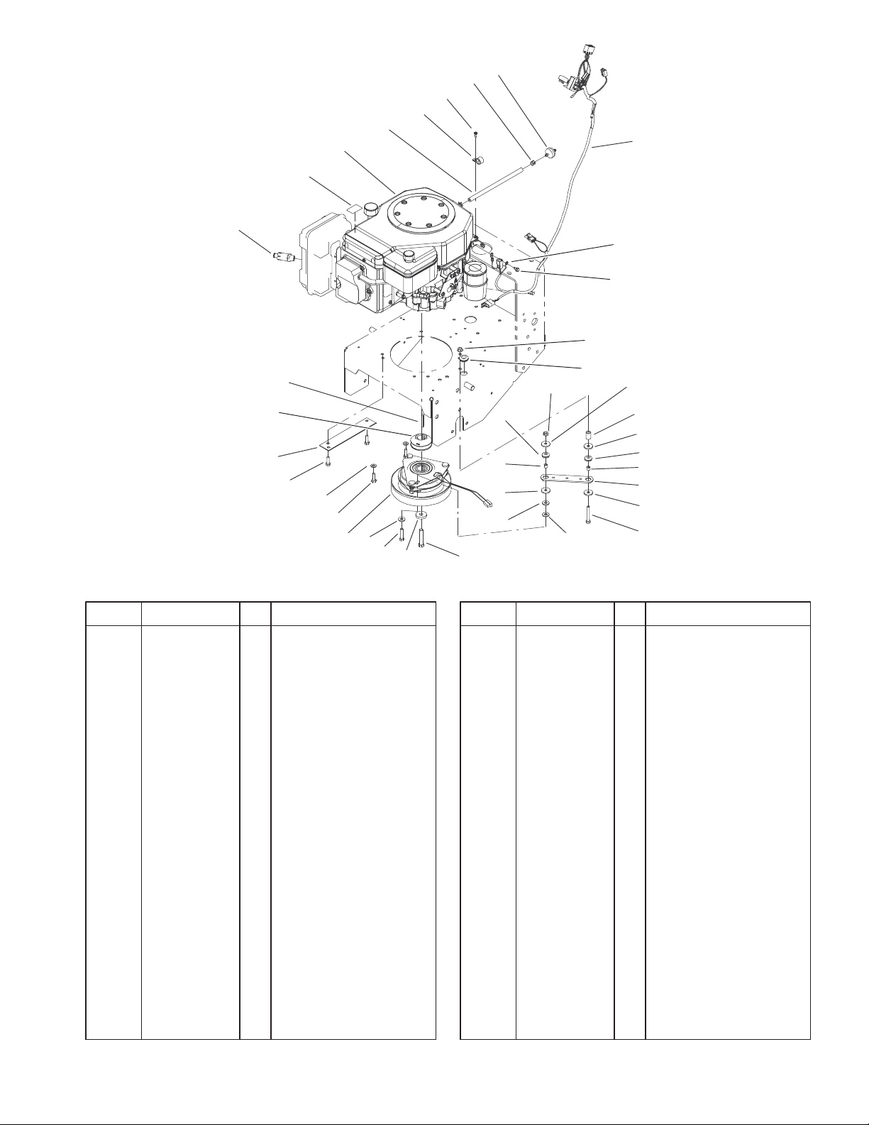
Engine and Clutch Assembly
DescriptionPart No. Qty.Ref. No. DescriptionPart No. Qty.Ref. No.
1 92–6877 1 Valve–Drain, Oil
2 106–0699 1 Decal–Warning, Hot
Surfaces
3 1 Engine–Kohler,
Cv15t–41604
4 47–2982 1 Hose–Fuel
5 2412–87 1 Clamp–Cable
6 32144–19 1 Screw–Forming,
Thread
7 2412–98 2 Clamp
8 56–6360 1 Filter–Fuel
9 104–9824 1 Wire Harness
10 3255–7 1 Washer–Lock/Ext
11 12–3270 1 Screw
12 32128–20 2 Nut–HF
13 237–124 1 Grommet
14 104–6373 1 Tube–Retainer
15 1–613235 4 Washer
16 1–633630 2 Grommet–Brake
17 1–633545 2 Spacer–Grommet
18 1–633543 1 Strap–Clutch/Brake
19 322–11 1 Screw–HH
21 3212–9 1 Screw–HH
22 112843 1 Washer
23 322–7 1 Screw–HH
24 105–2635 1 Clutch/Brake
22
16
17
15
26
26
21
14
15
16
17
18
15
19
25 33114–025 4 Screw–HH
26 3256–23 5 Washer–Flat
27 94–5847–01 1 Cover–Pulley
28 105–0827 1 Pulley–Drive
29 608006 1 Key–Square
*99 103–1964 1 Hose–Drain, Oil
Sheet No.: 2
Not serviced separately
* Not illustrated
3
Page 4
3327–395
1
1:3
2
16
15
17
18
10
14
10
12
10
11
10
22
23
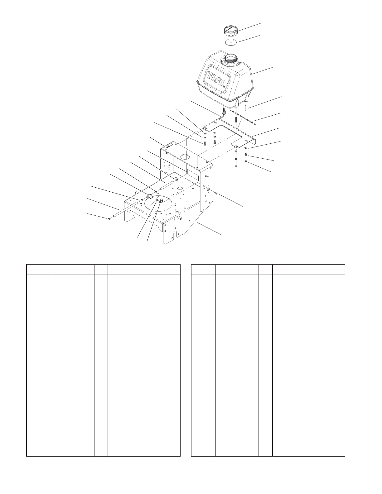
Fuel Tank Assembly
DescriptionPart No. Qty.Ref. No. DescriptionPart No. Qty.Ref. No.
1 88–3980 1 Gas Cap ASM
1:3 88–4010 1 Gasket–Cap, Gas
2 106–0730 1 Fuel Tank ASM
2:2 103–2605 1 Fitting–Fuel, Bulkhead
3 104–8121 2 Stud–Threaded
4 106–5496 1 Decal–Ground Speed
5 104–8102–01 1 Plate–Gate, Shift
6 3256–23 4 Washer–Flat
7 1–633349 2 Spring–Tank, Fuel
8 3296–47 2 Nut–Lock, NI
9 106–0546–01 1 Gear Frame ASM
10 2412–98 4 Clamp
11 47–2982 1 Hose–Fuel
12 1–603770 1 Valve–Fuel
14 47–2966 1 Hose–Fuel
15 322–4 2 Screw–HH
16 3253–4 2 Washer–Lock
17 95–2814 1 Decal–Shut Off, Fuel
18 98–0776 1 Decal–Caution
21 321–4 1 Screw–HH
22 3296–42 1 Nut–Lock, NI
23 2412–134 1 R–Clamp
2:2
6
21
9
3
4
5
6
7
8
Sheet No.: 4
4
Page 5
3327–395
3
2
1
3
4
5
6
7
8
9
10
11/12
7
13
14
15
16/17
18
25
2
24
Lower Control Assembly
DescriptionPart No. Qty.Ref. No. DescriptionPart No. Qty.Ref. No.
1 1–603402 2 Spring–Extension
2 3296–39 10 Nut–Lock, NI
3 3256–4 8 Washer–Flat
4 32128–40 4 Nut–Flange
5 323–8 2 Screw–HH
6 32103–25 2 Nut–Wing
7 3256–23 4 Washer–Flat
8 52–2890 2 Bushing–Nylon
9 3290–307 2 Pin–Hair
10 68–9690 2 Fitting–Rod
11 106–0611–01 1 LH Idler Bracket ASM
12 106–0612–01 1 RH Idler Bracket ASM
13 74–0040 4 Spacer–Pivot, Idler
14 95–2800 2 Pulley–Idler
15 3296–23 2 Nut–Lock, NI
16 67–6380–01 1 Bracket–Support, LH
17 67–6370–01 1 Bracket–Support, RH
18 323–16 2 Screw–HH
19 323–6 4 Screw–HH
20 95–2801 2 Spacer–Pulley
21 323–12 2 Screw–HH
22 106–0564 2 Spacer
23 51–4450 2 Screw–Leveler
24 3234–32 6 Screw–HHF
25 32128–23 6 Nut–HF
23
22
21
20
19
Sheet No.: 5
5
Page 6
3327–395
1
2
3
31
30
28:1
29
32
28
27
33
26
4
5
3
11
12
17
18
19
25
24
23
13
21
22
6
13
20
7
8
9
10
14
15
16
Sheet No.: 6
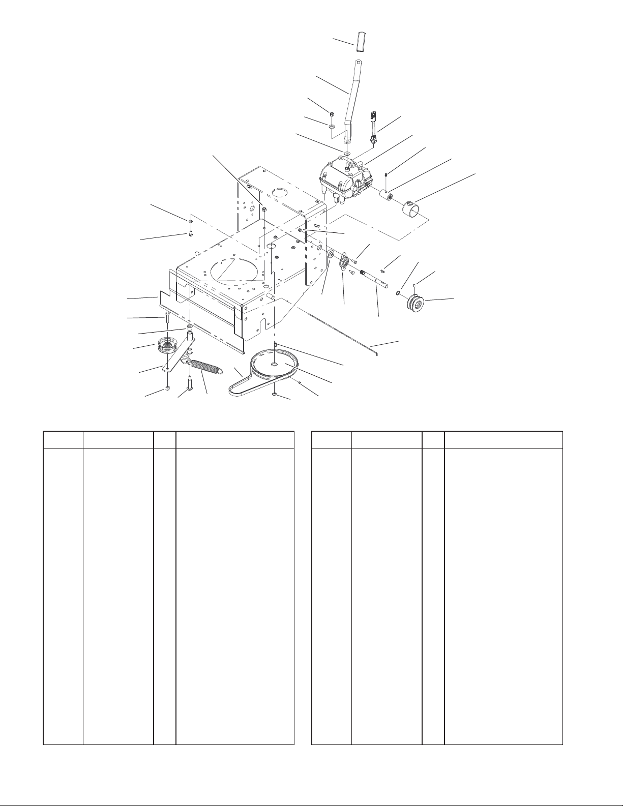
Transmission Drive Assembly
DescriptionPart No. Qty.Ref. No. DescriptionPart No. Qty.Ref. No.
1 47–1970 1 Grip
2 98–3274–03 1 Lever–Shift
3 3296–6 2 Nut–Lock, NI
4 98–5975 1 Washer–Belleville
5 1–323379 1 Washer
6 72–4320 1 Switch–Ball, N.o.
7 1–323500 1 Transmission
8 302–5 2 Fitting–Grease
9 1–323680 2 Coupler
10 51–4220 2 Guard–Coupler
11 3296–42 4 Nut–Lock, NI
12 321–4 4 Screw–HH
13 3257–5 3 Key–Woodruff
14 32151–62 2 Ring–Retaining
15 3245–9 2 Screw–Set
16 105–2698 2 Pulley–Transmission
17 1–323252 2 Bearing–Shaft
18 1–323254 2 Flange–Output
19 104–1102 2 Shaft–Output
20 95–1529 1 Rod–Shield
21 105–5646 1 Pulley–Driven
22 3245–1 1 Screw–Set, HSH
23 32120–64 1 Ring–Snap, External
24 105–5668 1 V–Belt
25 68–2190 1 Spring
26 27–6230 1 Bolt–Wheel
27 3296–39 1 Nut–Lock, NI
28 16–7509 1 Lever–Idler
28:1 256–155 2 Bushing–Flange
29 62–4540 1 Pulley
30 323–9 1 Screw–HH
31 95–1526 1 Shield–Trailing
32 322–2 4 Screw–HH
33 3253–4 4 Washer–Lock
6
Page 7
3327–395
1
2
3
5
4
6
8
10
26
25
24
23
22
21
20
29
28
27
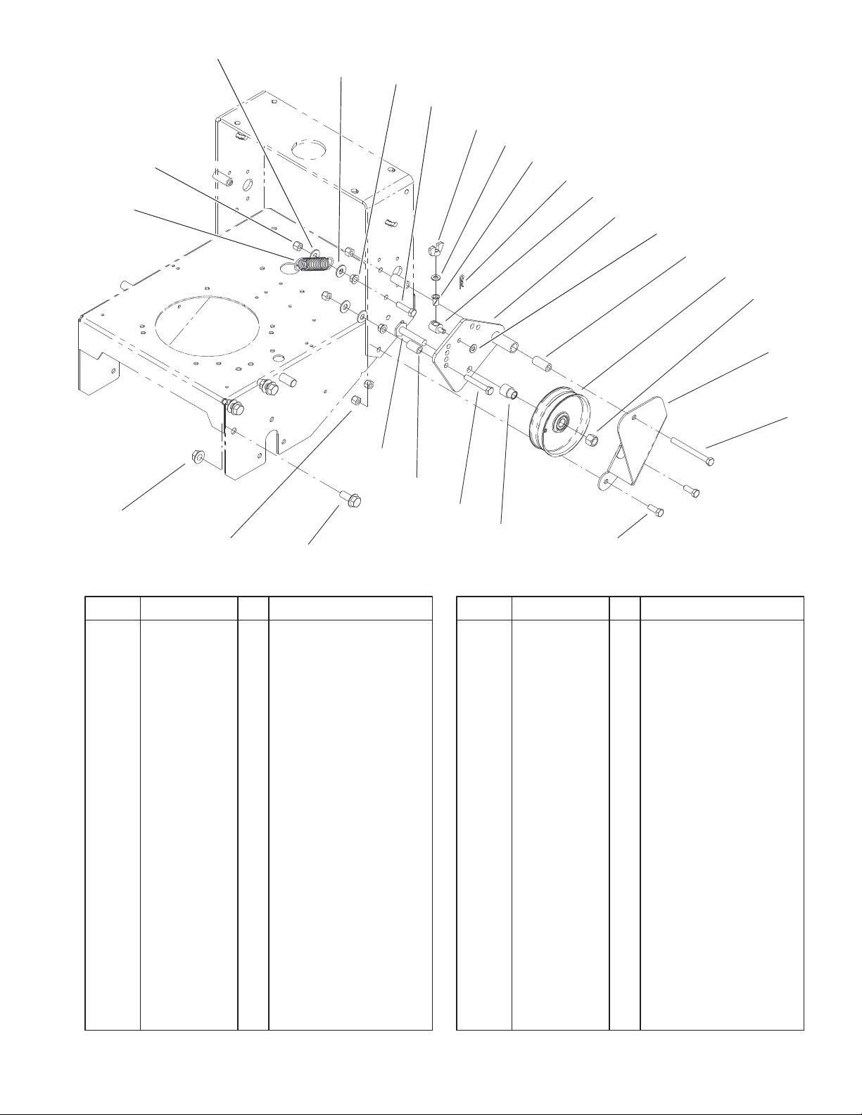
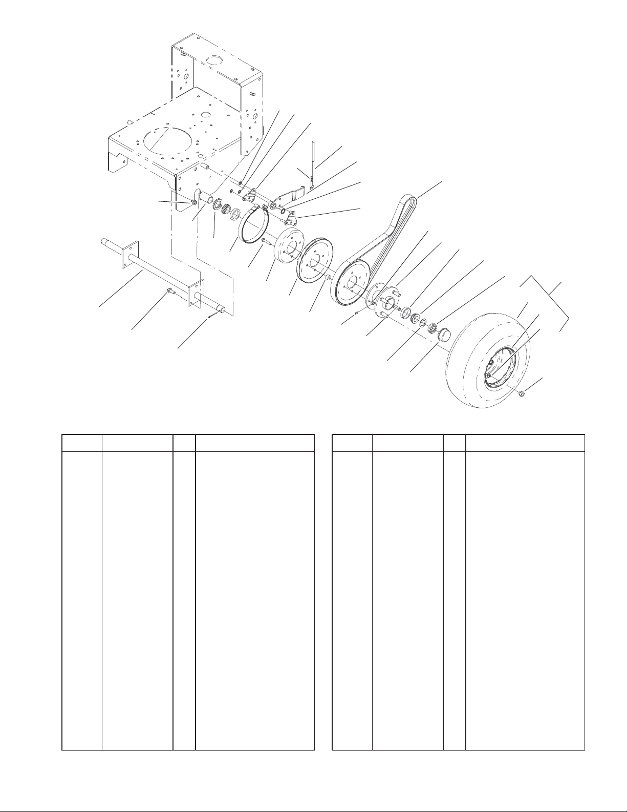
Wheel Drive and Brake Assembly
DescriptionPart No. Qty.Ref. No. DescriptionPart No. Qty.Ref. No.
1 32151–56 2 Ring–Retaining,
External
2 32151–72 4 Ring–Retaining
3 105–4651–01 2 Plate–Link, Brake
4 3290–307 2 Pin–Hair
5 51–4580 2 Rod–Brake
6 106–5537–01 2 Brake Arm ASM
8 32151–40 2 Ring–Retaining
9 105–4652–01 2 Brake Link ASM
10 51–4290 2 V–Belt
11 3296–29 8 Nut–Lock, NI
12 1–413333 2 Hub–Wheel ASM
12:2 254–72 2 Bearing–Cup, Tapered
12:3 302–19 1 Fitting–Grease
12:4 1–633926 4 Stud–Wheel
13 254–94 4 Bearing–Cone, Taper
14 1–809082 2 Nut–SHH
15 104–6321 2 Wheel And Tire ASM
15:1 104–6322 1 Tire
15:2 104–6323 1 Wheel
15:3 232–27 1 Stem–Valve
16 242–50 8 Nut–Lug
17 241–119 2 Cap–Dust
18 1–523157 2 Washer–Spacer
19 51–4170 8 Spacer–Pulley
20 51–4160–03 4 Pulley–Wheel
19
12:3
9
11
12
12:2
13
14
12:4
18
17
21 1–323261 2 Drum–Brake
22 322–8 8 Screw–HH
23 1–323262 2 Band–Brake
24 1–543511 2 Seal–Grease
25 104–1197 2 Spacer–Wheel
26 32128–21 6 Nut–HF
27 1–806800 2 Pin–Cotter
28 3234–11 6 Screw–HHF
29 104–1196–01 1 Axle ASM
15
15:1
15:2
15:3
16
Sheet No.: 7
7
Page 8
3327–395
4
6
1
2
3
5
30:3
7
8
9
10
11
30:2
13
12
14
15
16
2
6
31
29
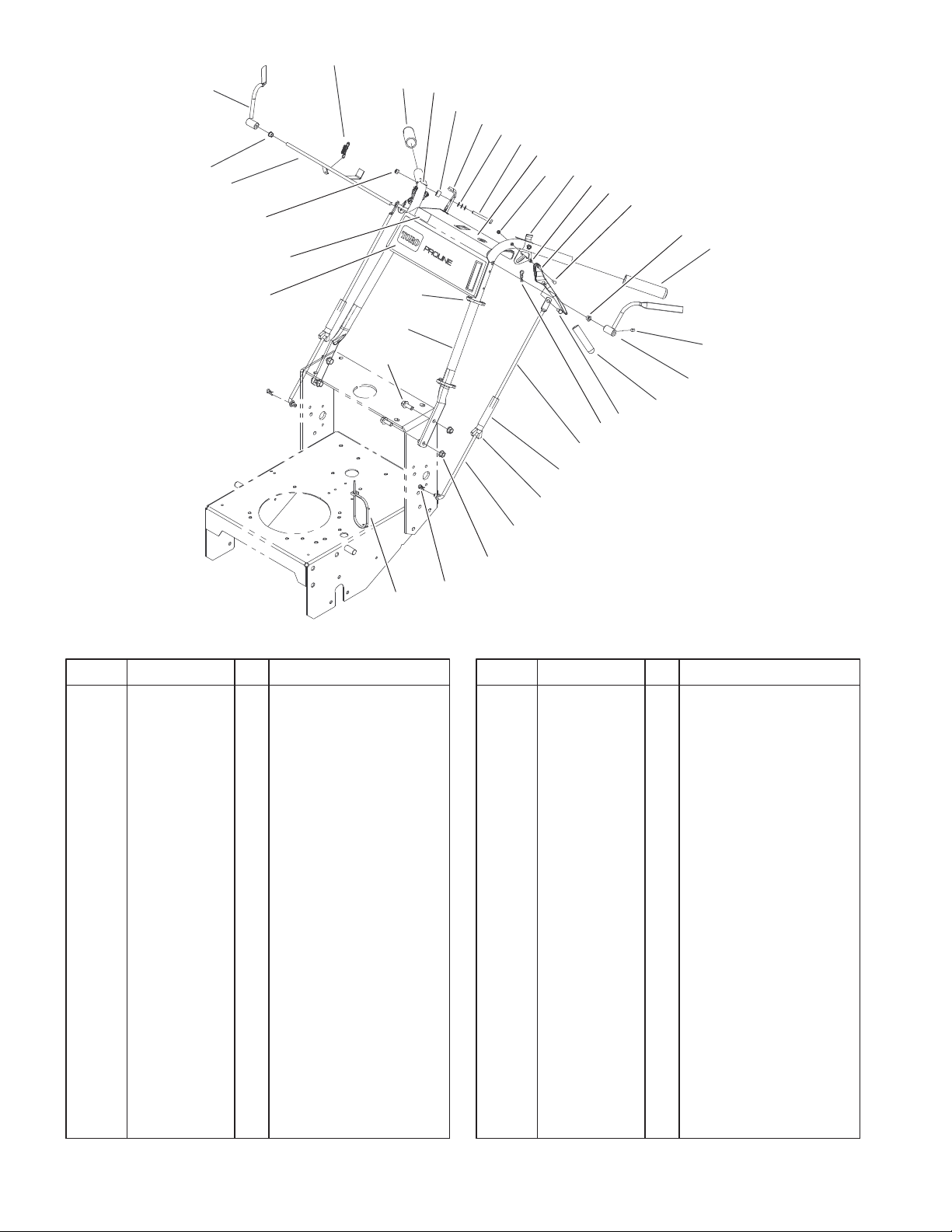
Handle Assembly
DescriptionPart No. Qty.Ref. No. DescriptionPart No. Qty.Ref. No.
1 106–5486 1 RH Opc Lever ASM
2 1–303365 2 Bushing–Nylon
3 104–9803 1 Rod ASM
4 1–303363 1 Spring–Extension
5 3296–42 2 Nut–Lock, NI
6 104–9838 2 Grip–Foam
7 105–4111 2 Decal–Lock, Neutral
8 1–323549 2 Spacer
9 106–5521 1 Latch–Thumb, RH
10 1–303435 6 Washer–Spring
11 321–18 2 Screw–HH
12 1–803001 2 Nut
13 106–5520 1 Latch–Thumb, LH
14 1–806340 2 Pin–Roll
15 1–302006 2 Drive Lever ASM
15:1 1–303021 1 Grip–Lever, Drive
16 1–808250 2 Pin–Clevis
18 1–803322 2 Screw–Set
19 106–5485 1 LH Opc Lever ASM
20 1–808286 2 Pin–Clevis
21 1–806003 2 Pin–Hair
22 106–0613 2 Linkage–Drive Wheel
23 95–1504 2 Turnbuckle
24 32103–3 2 Nut–Wing
25 95–1506 2 Rod–Control, Lower
26 32128–21 4 Nut–HF
30
28
28
27
18
19
15:1
20
21
22
23
24
25
26
Sheet No.: 8
27 3290–307 2 Pin–Hair
28 3290–378 3 Tie–Cable
29 3234–11 4 Screw–HHF
30 105–3174 1 Gear/Pg Handle ASM
30:2 106–5514 1 Decal–Control Panel
30:3 98–4387 1 Decal–Protection, Ear
31 106–5501 1 Decal–Control,
Throttle
8
Page 9
4
5
6
3327–395
1:1
1:2
3
2
1
22
18
23
17
19
21
17
7
7
8
9
7
11
12
13
14
15
16
20
19
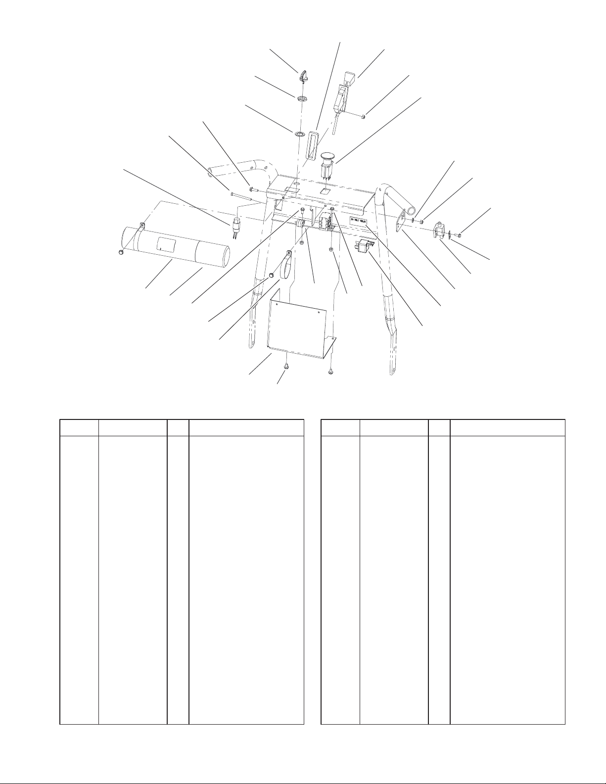
Control Panel Assembly
DescriptionPart No. Qty.Ref. No. DescriptionPart No. Qty.Ref. No.
1 29–5560 1 Switch–On/Off
1:1 218–461 1 Nut–HH
1:2 3254–5 1 Washer–Tooth
2 32105–14 2 Screw
3 32105–13 2 Screw–SHH
4 63–8360 1 Key–Ignition
5 106–5487 1 Gasket–Throttle
6 105–4114 1 Control–Throttle
7 3296–2 6 Nut–Lock
8 95–7489 1 Switch–PTO
9 3256–14 2 Washer–Flat
11 32144–1 2 Screw–Taptite
12 82–4570 1 Plate–Switch
13 95–1653 1 Switch–Pole, Single
14 105–4137–03 1 Plate–Mounting,
Switch
15 105–4146 1 Decal–Relay, 24 Volt
16 105–4145 1 Relay–Speedometer
17 3290–321 2 Screw–HWH
18 2412–134 1 R–Clamp
19 32104–76 4 Screw
20 105–4112–03 1 Bracket–Cover
21 2412–120 2 R–Clamp
22 104–7050 1 Housing–Manual
23 104–7048 1 Cap–Housing
Sheet No.: 9
9
Page 10

3327–395
6
5
3
4
2
24
1
7
8
9
10
23
22
21
17
20
19:4
19:2
19:1
19
19:3
19:5
19:4
18
Carrier Frame Assembly
DescriptionPart No. Qty.Ref. No. DescriptionPart No. Qty.Ref. No.
1 106–0706 1 Carrier Frame ASM
1:2 32148–9 3 Insert–Nut
1:3 94–1291 4 Bushing–Special
1:4 302–5 2 Fitting–Grease
2 105–3165–01 1 Cover–Frame, Carrier
3 106–0719 1 Decal–Proline
4 240–3 1 Grommet–Rubber
5 106–0565 3 Washer–Rubber
6 104–8587 3 Knob
7 12–3270 2 Screw
8 106–5473–01 1 Shield–Heat
9 3290–199 2 Nut–Speed
10 104–1105 4 Spacer–Support, Deck
11 1–513336 2 Bushing–Deck
12 321–5 2 Screw–HH
13 3256–22 2 Washer–Flat
14 32120–33 2 Ring–Retaining
15 105–0842 4 Spacer
16 106–0635 2 Decal–HOC
17 105–3159–01 2 Castor Fork ASM
18 32153–5 2 Nut–Lock
19 100–6451 2 Castor Wheel ASM
19:1 232–27 1 Stem–Valve
19:2 302–11 1 Fitting–Lube, 45
19:3 83–4740 1 Bearing
19:4 62–5580 2 Bearing–Outside
1:4
11
12
13
14
1:2
15
16
1:3
Sheet No.:2
19:5 100–6452 1 Tire–Tubeless
20 100–6453 2 Bushing–Spanner
21 325–19 2 Screw–HH
22 283–71 2 Pin–Lynch
23 3–6781 8 Washer–Thrust
24 106–5510 1 Decal–Service, Gear
Tb
10
Page 11

18
21
20
15
19
1:9
17
3
1:2
2
1:8
1
5
16
14
1:3
4
6
5
1:10
1:7
1:4
7
1:5
1:6
8
3327–395
Spindle, Pulley and Belt Assembly
DescriptionPart No. Qty.Ref. No. DescriptionPart No. Qty.Ref. No.
1 106–0615 1 36” Deck ASM
1:2 32148–9 2 Insert–Nut
1:3 104–8185 1 Decal–Belt Routing
1:4 68–8340 1 Decal–Torque
1:5 43–8480 1 Decal–Danger
1:6 106–5532 1 Decal–Antiscalp
1:7 67–5360 1 Decal–Danger
1:8 104–8569 1 Decal–Warning
1:9 106–0703 1 Decal
1:10 66–1340 1 Decal–Danger
2 51–3530 1 V–Belt–Drive, Deck
3 1–633166 1 Pulley–Idler
4 98–5975 1 Washer–Belleville
5 3256–24 2 Washer–Flat
6 323–6 1 Screw–HH
7 3231–22 11 Screw–CARR
8 106–0785 1 Spindle Housing ASM
9 32128–21 12 Nut–HF
10 56–2390 2 Blade
11 92–9820 2 Stiffener–Blade
12 3256–6 2 Washer–Flat
13 44–2200 2 Screw–Blade
14 106–0787 1 Spindle Housing ASM
15 323–12 1 Screw–HH
16 51–3641 1 Sleeve–Pivot, Idler
17 3211–5 1 Screw–HH
13
9
10
11
12
Sheet No.:3
18 51–3660 1 Pulley–Idler
19 105–0889 1 Idler Arm ASM
20 3296–5 1 Nut–Lock, NI
21 105–2673 1 Spring–Extension
11
Page 12

3327–395
2
1
3
4
5
6
7
5
Spindle Assembly No. 106–0785
DescriptionPart No. Qty.Ref. No. DescriptionPart No. Qty.Ref. No.
1 3219–7 1 Nut–Hex
2 7–4150 1 Washer
3 104–1117 1 Pulley And Hub ASM
4 106–0873 1 Shield–Bearing
5 104–6325 2 Bearing
6 106–0819 1 Housing–Spindle
7 106–0795 1 Spacer–Bearing
8 106–0781 1 Shaft–Spindle
8
Sheet No.:A1
12
Page 13

3327–395
2
1
3
4
5
6
7
5
Spindle Assembly No. 106–0787
DescriptionPart No. Qty.Ref. No. DescriptionPart No. Qty.Ref. No.
1 3219–7 1 Nut–Hex
2 7–4150 1 Washer
3 104–1118 1 Pulley And Hub ASM
4 106–0873 1 Shield–Bearing
5 104–6325 2 Bearing
6 106–0819 1 Housing–Spindle
7 106–0795 1 Spacer–Bearing
8 106–0782 1 Shaft–Spindle
8
Sheet No.:A2
13
Page 14

3327–395
1:2
6
2
3
4
5
7
8
1
20
20
19
18
17
4
12
16
11
13
14
15
12
9
10
Sheet No.:4
Deck Assembly
DescriptionPart No. Qty.Ref. No. DescriptionPart No. Qty.Ref. No.
1 105–4623 1 Deflector ASM
1:2 93–1122 1 Decal–Danger
2 105–4622 1 Spacer
3 104–8554 1 Spring–Torsion
4 3296–29 2 Nut–Lock, NI
5 106–0565 2 Washer–Rubber
6 104–8587 2 Knob
7 106–5475–01 1 Cover ASM
8 106–0684 2 Front Pin ASM
9 3220–3 2 Nut–Jam
10 1–613204 2 Balljoint
11 104–1156 2 Spacer
12 3296–39 4 Nut–Lock, NI
13 106–3365 2 Rear Pin ASM
14 3290–256 6 Pin–Hair
15 323–10 2 Screw–HH
16 323–8 2 Screw–HH
17 3256–23 2 Washer–Flat
18 98–5967 1 Spacer
19 68–2730 2 Wheel–Gage
20 322–50 2 Screw–HH
14
Page 15

3327–395
2
1
4
4
5
6:1
6:2
12
11
10
9
Drive Belt and Tensioner Assembly
DescriptionPart No. Qty.Ref. No. DescriptionPart No. Qty.Ref. No.
1 106–5492 1 Belt–Drive, PTO
2 3296–39 1 Nut–Lock, NI
4 1–809107 3 Washer–Hardened
5 104–6377 1 Tube–Idler
6 106–0734 1 Idler Arm ASM
6:1 1–513034 2 Sleeve–Bearing
6:2 302–5 1 Fitting–Grease
7 323–42 1 Screw–HH
8 323–6 1 Screw–HH
9 98–5975 1 Washer–Belleville
10 3256–24 1 Washer–Flat
11 1–413099 1 Pulley–Idler
12 105–8443 1 Spring–Extension
6
6:1
4
8
7
Sheet No.:5
15
Page 16

3327–395
Presence
Switch
(No Operator)
Electrical Schematic
Operator
GND
HR MTR
(OPTIONAL)
BK
BK
(OPEN = ON)
(CLOSED = OFF)
KEY SWITCH
1
2
29–5560
Relay
K1
Interlock
PK
PK
W
PTO Switch
(Off)
W
2
1
PK
Pistol Grip M.S. GEAR 15 KOHLER
Y
HR MTR
(OPTIONAL)
3
TYY
4
PK
5
Clutch
W
Switch
(In Neutral)
10A
Neutral
Y
BU
F1
5
8
4
7
16
REG
AC
MAG
IGNITION
MODULE
SPARK PLUG
ENGINE
OR
ORANGE
Y
YELLOW
GY
GREY
W
WHITE
GN
GREEN
VIO
VIOLET
BU
BLUE
T
TAN
BN
BROWN
R
RED
BK
BLACK
WIRE COLOR CODES
PK
PINK
Page 17

25
3327–395
24
Crankcase Assembly – Kohler Model CV15T–41604
DescriptionPart No. Qty.Ref. No. DescriptionPart No. Qty.Ref. No.
1 12 032 03–S 1 Seal–Crankshaft
2 12 522 18–S 1 Shortblock
3 12 445 02–S 1 Strap–Lifting
4 M–839025–S 1 Screw–HF M8x1.25x22
5 24 380 13–S 4 Dowel–Locating
6 12 755 49–S 1 Kit–Camshaft (Incl.7–8)
7 12 089 31–S 1 Spring–Actuating
8 12 422 07–S A/R Shim–Camshaft, White
8 12 422 08–S 1 Shim–Camshaft, Blue
8 12 422 09–S A/R Shim–Camshaft, Red
8 12 422 10–S A/R Shim–Camshaft,Yellow
8 12 422 11–S A/R Shim–Camshaft, Green
8 12 422 12–S A/R Shim–Camshaft, Gray
8 12 422 13–S A/R Shim–Camshaft, Black
9 12 144 27–S 1 Shaft–Balance
10 12 874 07–S 1 Piston w/Ring Set STD
(Incl. 11,12)
10 12 874 08–S 1 Set–Piston w/Ring .25
10 12 874 09–S 1 Set–Piston w/Ring .50
10 12 874 11–S 1 Set–Piston w/Ring .08
11 12 018 02–S 2 Retainer–Piston Pin
12 12 108 07–S 1 Ring Set STD
12 12 108 08–S 1 Ring Set .25
12 12 108 09–S 1 Ring Set .50
13 12 067 05–S 1 Rod–Connecting, STD
13 12 067 06–S 1 Rod–Connecting .25
14 12 380 01–S 1 Pin–Governor
Regulating
15 12 043 05–S 1 Gear–Governor
16 M–631005–S 1 Washer–Plain, 6mm
17 12 144 02–S 1 Shaft–Governor Gear
18 52 139 09–S 1 Plug–Cup
19 12 755 64–S 1 Kit–Governor Cross
Shaft (Incl. 23)
20 X–25–102–S 1 Washer–Plain, 1/4
21 12 032 01–S 1 Seal–Governor Cross
Shaft
22 M–631015–S 1 Washer–Plain, 6mm
23 12 154 05–S 1 Clip–Hitch Pin
24 12 014 30–S 1 Crankshaft ASM
(Incl. 25)
25 12 139 01–S 1 Plug–Cup
* 12 755 93–S 1 Set–Gasket
* Not illustrated
Order Parts from Kohler
17
Page 18

3327–395
Oil Pan and Lubrication Assembly
Kohler Model CV15T–41604
DescriptionPart No. Qty.Ref. No. DescriptionPart No. Qty.Ref. No.
1 12 038 01–S 1 Dipstick ASM(Incl. 2–3)
2 25 755 13–S 1 Kit–Oil Fill Cap (Incl. 3)
3 12 153 03–S 1 O Ring–Dipstick
4 12 153 02–S 1 O Ring–Upper Oil Fill
Tube
5 12 123 04–S 1 Tube–Oil Fill
6 M–545020–S 1 Screw–HF, M5x0.8x20
7 12 153 01–S 1 O Ring–Lower Oil Fill
Tube
8 25 162 07–S 1 Screen–Oil Pickup
9 12 096 03–S 1 Cover–Oil Pickup
Screen
10 M–545016–S 1 Screw–HF, M5x0.8x16
11 52 050 02–S 1 Filter–Oil
12 12 199 50–S 1 Pan ASM – Oil
(Incl.13, 17–20)
13 25 462 09–S 1 V alve–Oil Pressure
Relief
14 25 139 57–S 1 Plug–Pipe, 3/8 SH
15 25 139 52–S 1 Plug–Pipe,1/8
16 25 139 62–S 1 Plug–Pipe, 3/8 HSH
17 12 393 01–S 1 Pump–Oil
18 12 153 06–S 1 O Ring–Oil Pump
Cover
19 12 096 34–S 1 Cover–Oil Pump
20 M–545016–S 3 Screw–HF, M5x0.8x16
21 12 032 03–S 1 Seal–Oil (PTO End)
22 24 086 16–S 11 Screw–HF,
M8x1.25x45
23 24 086 17–S 1 Screw–HF,
M8x1.25x45
Order Parts From Kohler
18
Page 19

25
3327–395
Cylinder Head, Valves And Breather Assembly
Kohler Model CV15T–41604
DescriptionPart No. Qty.Ref. No. DescriptionPart No. Qty.Ref. No.
1 12 351 01–S 2 Lifter–Valve
2 12 755 81–S 1 Kit–Cylinder Head
(Incl. 3–13, 18–21, 25,
Carburator Gasket
12 041 01–S(2),
Exaust Manifold
Gasket 12 041 03–S,
Air Cleaner Gasket
12 041 02–S)
3 12 411 01–S 2 Rod–Push
4 12 041 10–S 1 Gasket–Cylinder Head
5 12 017 01–S 1 Valve–Intake STD
5 12 017 02–S 1 Valve–Intake .25
6 12 016 01–S 1 Valve–Exhaust STD
6 12 016 02–S 1 Valve–Exhaust, .25
7 12 318 19–S 1 Head – Cylinder
8 12 468 05–S 1 Washer–Plain 13/32
9 12 112 13–S 1 Spacer–Head Bolt
Exhaust Port
10 12 086 15–S 5 Screw–HF M10x1.5x81
11 12 089 01–S 2 Spring–Valve
12 12 173 01–S 2 Cap–Valve Spring
13 12 755 03–S 2 Kit–Retainer
14 25 237 14–S 2 Clamp–Hose
15 12 326 03–S 1 Hose–Breather
16 M–645020–S 3 Screw–HF M6x1.0x20
17 12 096 07–S 1 Cover–Valve w/Nipple
18 24 032 05–S 1 Seal–Valve Stem
19 M–640034–S 2 Screw–HF M6x1.0x34
20 12 599 03–S 2 Pivot–Rocker Arm
21 25 186 01–S 2 Arm–Rocker
22 M–545010–S 1 Screw–HF M5x0.8x10
23 12 018 01–S 1 Retainer–Breather
Reed
24 12 402 02–S 1 Reed–Breather
25 25 139 60–S 1 Plug–Pipe, HSH 1/8
Order Parts From Kohler
19
Page 20

3327–395
19
17
1
2
3
4
8
9
5
10
18
16
15
14
Ignition and Electrical Assembly
Kohler Model CV15T–41604
DescriptionPart No. Qty.Ref. No. DescriptionPart No. Qty.Ref. No.
1 12 086 14–S 1 Screw–HF,M10x1.5x46
2 12 468 03–S 1 Washer–Plain, 3/8
3 12 162 03–S 1 Screen–Grass
4 25 086 47–S 4 Bolt–Shoulder
5 12 157 03–S 4 Fan
6 X–42–15–S 1 Key
7 236602–S 1 Connector–Rectifier,
Regulator(3 contact)
8 12 403 01–S 1 Rectifier–Unregulated,
15 amp
9 X–22–11–S 2 Washer – Lock
10 M–639016–S 2 Screw–HF, M6x1.0x16
11 41 155 03–S 1 Connector
12 12 025 33–S 1 Flywheel
13 M–548025–S 2 Screw–HH M5x0.8x25
14 237878–S 1 Kit–Stator, 15 Amp
15 12 132 06–S 1 Spark Plug
16 X–728–1–S 2 Clip–Cable
17 M–545010–S 2 Screw–HF, M5x0.8x10
18 12 584 05–S 1 Module–Ignition
19 M–545020–S 2 Screw–HF, M5x0.8x20
* 25 518 05–S 1 Lead–Black, Rectifier/
Regulator,(5”–14Gauge
Uninsulated Push On
13
7
6
12
1
1
Tab Terminals)
* 12 518 01–S 1 Lead–White, Ground
To Kill, (19”–18 Gauge
Fully Insulated Push
On Tab and
Uninsulated Push On
Tab Terminals
* 25 518 12–S 1 Lead–Black,Ground,
(5”–12Gauge–Insulated
Grip Barrel Eyelet
Terminals
* Not illustrated
Order Parts From Kohler
20
Page 21

1
2
9
1
8
3
7
6
3327–395
6
5
Blower Housing And Baffles Assembly
Kohler Model CV15T–41604
DescriptionPart No. Qty.Ref. No. DescriptionPart No. Qty.Ref. No.
1 M–550010–S 6 Screw–HF, M5x0.8x10
2 12 096 29–S 1 Cover–Starter
3 12 027 68–S 1 Housing–Blower
4 12 063 10–S 1 Baffle–Intake, Side
5 12 063 08–S 1 Baffle–Cylinder Head
6 M–545010–S 9 Screw–HF, M5x0.8x10
7 12 313 03–S 1 Grommet–Spark Plug
leads
8 12 063 19–S 1 Baffle–Cylinder
9 12 146 07–S 1 Plate–Blower Housing
* 12 146 21–S 1 Decal–Hoursepower
4
* Not illustrated
Order Parts From Kohler
21
Page 22

3327–395
Starter Assembly
Kohler Model CV15T–41604
DescriptionPart No. Qty.Ref. No. DescriptionPart No. Qty.Ref. No.
1 M–550010–S 5 Screw–HF, M5x0.8x10
2 12 165 01–S 1 Starter ASM
Retractable (Incl. 3–9)
3 12 081 01–S 1 Housing–Starter
4 12 160 01–S 1 Rope–Starter
5 25 166 01–S 1 Handle–Recoil
6 12 089 06–S 1 Spring & Keeper
7 12 093 01–S 1 Pulley
8 12 757 06–S 1 Kit–Dog Repair
(incl. 9)
9 41 086 09–S 1 Screw–Posidrive
10 15 109 01–S 1 Cup–Drive
* 12 113 07–S 1 Decal–Starting
* Not illustrated
Order Parts From Kohler
22
Page 23

8
6
7
6
5
4
3327–395
3
Fuel System Assembly
Kohler Model CV15T–41604
DescriptionPart No. Qty.Ref. No. DescriptionPart No. Qty.Ref. No.
1 M–641060–S 2 Nut–HF M6x1.0
2 M–629116–S 2 Stud M6x1.0x116
3 12 853 80–S 1 Kit–Carburetor
w/Gaskets (Incl. 4–6)
4 12 041 02–S 1 Gasket–Air Cleaner
5 12 053 80 1 Carburetor ASM (For
Information Only Not
Available Separately)
(Service With Kits
12 757 02–S Float Kit
12 757 03–S Carb.
Repair Kit and
12 757 08–S Choke
Repair Kit)
6 12 041 01–S 2 Gasket–Carburetor
7 12 265 04–S 1 Deflector–Heat
8 47 154 01–S 1 Clip–Cable
* 12 757 02–S 1 Kit–Float
* 12 757 08–S 1 Kit–Choke Repair
* 12 757 03–S 1 Kit–Carburetor Repair
2
1
* Not illustrated
Order Parts From Kohler
23
Page 24

3327–395
14
1
16
5
9
15
13
8
7
6
2
3
4
12
10
Engine Controls Assembly
Kohler Model CV15T–41604
DescriptionPart No. Qty.Ref. No. DescriptionPart No. Qty.Ref. No.
1 12 079 07–S 1 Linkage–Choke
2 12 237 01–S 1 Clamp–Cable
3 M–664020–S 2 Screw–Lobed Socket
M6x1.0x20
4 M–545016–S 1 Screw–HF M5x .08x16
5 12 536 01–S 1 Control–Speed ASM
(Incl. 6–8)
6 M–443025–S 1 Screw–SPH,
M4x0.7x25
7 12 089 11–S 1 Spring–Choke
Adjustment
8 12 089 23–S 1 Spring–Choke Return
9 12 089 19–S 1 Spring–Governor
10 12 755 83–S 1 Kit – Governor Lever
(Incl. 11–13)
11 12 100 07–S 1 Nut–HF
12 52 211 04–S 1 Bolt – Round HD
13 12 090 28–S 1 Lever–Governor
14 25 158 08–S 1 Bushing–Linkage
Retaining
15 12 079 01–S 1 Linkage–Throttle
16 25 158 11–S 1 Bushing–Throttle
Linkage
11
Order Parts From Kohler
24
Page 25

3327–395
2
3
4
1
5
9
12
Air Cleaner Assembly
Kohler Model CV15T–41604
DescriptionPart No. Qty.Ref. No. DescriptionPart No. Qty.Ref. No.
1 12 743 02–S 1 Kit–Air Cleaner
(Incl. 2–12)
2 25 341 03–S 1 Knob–Air Cleaner
Cover
3 12 096 38–S 1 Cover–Air Cleaner
4 12 083 12–S 1 Element–Precleaner
5 12 083 10–S 1 Element–Air Cleaner
(Incl. 6–8)
6 12 743 12–S 1 Kit–Seal (Incl. 7–8)
7 12 100 08–S 1 Nut–Wing
8 12 032 11–S 1 Seal
9 12 094 07–S 1 Base–Air Cleaner
(Incl. 10,11)
10 12 072 04–S 1 Stud–M6x1.0x66
11 12 086 01–S 2 Screw–#10 Hi–Lo
Thread Forming
12 12 041 02–S 1 Gasket–Air Cleaner
* 12 113 04–S 1 Decal–Air Cleaner
7
6
8
10
11
* Not illustrated
Order Parts From Kohler
25
Page 26

3327–395
8
1
2
3
4
9
5
7
Exhaust Assembly
Kohler Model CV15T–41604
DescriptionPart No. Qty.Ref. No. DescriptionPart No. Qty.Ref. No.
1 12 068 44–S 1 Muffler
2 25 072 04–S 2 Stud M8x1.25x33
3 12 041 03–S 1 Gasket–Exhaust
Manifold
4 X–25–78–S 1 Washer–Plain,1/4
5 M–545016–S 1 Screw–HF, M5x0.8x16
6 M–841080–S 2 Nut–HF, M8x1.25
7 M–645016–S 2 Screw–HF, M6x1.0x16
8 M–645025–S 2 Screw–HF, M6x1.0x25
9 12 126 71–S 1 Bracket–Muffler
6
Obtain Parts From Kohler
26
Page 27

Date
Maintenance Record
27
Page 28

 Loading...