

Page 1

Form No. 3354–528 Rev B
Rotary Brush
Groundsmaster) 4000–D & 4100–D
Model No. 30426—Serial No. 260000001 and Up
Operator’s Manual
English (EN)
Page 2

Contents
Introduction
Introduction 2. . . . . . . . . . . . . . . . . . . . . . . . . . . . . . . . .
Safety 2. . . . . . . . . . . . . . . . . . . . . . . . . . . . . . . . . . . . . .
Before Operating 3. . . . . . . . . . . . . . . . . . . . . . . . . .
While Operating 3. . . . . . . . . . . . . . . . . . . . . . . . . . .
Maintenance 3. . . . . . . . . . . . . . . . . . . . . . . . . . . . . .
Sound Pressure Level 4. . . . . . . . . . . . . . . . . . . . . . .
Sound Power Level 4. . . . . . . . . . . . . . . . . . . . . . . .
Vibration Level 4. . . . . . . . . . . . . . . . . . . . . . . . . . . .
Safety and Instruction Decals 4. . . . . . . . . . . . . . . . .
Specifications 5. . . . . . . . . . . . . . . . . . . . . . . . . . . . . . . .
General Specifications 5. . . . . . . . . . . . . . . . . . . . .
Optional Equipment 5. . . . . . . . . . . . . . . . . . . . . . . .
Setup 6. . . . . . . . . . . . . . . . . . . . . . . . . . . . . . . . . . . . . .
Remove Front Cutting Unit and Lift Arms 7. . . . . .
Mount Brush Assembly 9. . . . . . . . . . . . . . . . . . . . .
Adjust Counterbalance
(Groundsmaster 4100–D only) 11. . . . . . . . . . . . . .
Adjust Lift Pressure
(Groundsmaster 4000–D only) 11. . . . . . . . . . . . . .
Adjust Drop Speed 12. . . . . . . . . . . . . . . . . . . . . . . . .
Check Chain Tension 12. . . . . . . . . . . . . . . . . . . . . . .
Check Castor Wheel Tire Pressure 12. . . . . . . . . . . . .
Operation 13. . . . . . . . . . . . . . . . . . . . . . . . . . . . . . . . . . .
Operation 13. . . . . . . . . . . . . . . . . . . . . . . . . . . . . . . .
Operating Tips 13. . . . . . . . . . . . . . . . . . . . . . . . . . . .
Adjust Brush Down Pressure 13. . . . . . . . . . . . . . . . .
Ground Speed 13. . . . . . . . . . . . . . . . . . . . . . . . . . . . .
Switch Operation 13. . . . . . . . . . . . . . . . . . . . . . . . . .
Maintenance 14. . . . . . . . . . . . . . . . . . . . . . . . . . . . . . . . .
Greasing the Brush 14. . . . . . . . . . . . . . . . . . . . . . . . .
Adjusting Chain Tension 15. . . . . . . . . . . . . . . . . . . .
Changing Brush Elements 15. . . . . . . . . . . . . . . . . . .
Servicing Bumper Bushings 16. . . . . . . . . . . . . . . . . .
Servicing Castor Wheel And Bearing 16. . . . . . . . . .
Hydraulic Schematic 17. . . . . . . . . . . . . . . . . . . . . . .
Electrical Schematic 18. . . . . . . . . . . . . . . . . . . . . . . .
The Toro General Commercial Products Warranty 20. . .
Page
Read this manual carefully to learn how to operate and
maintain your product properly. The information in this
manual can help you and others avoid injury and product
damage. Although Toro designs and produces safe
products, you are responsible for operating the product
properly and safely.
Whenever you need service, genuine Toro parts, or
additional information, contact an Authorized Service
Dealer or Toro Customer Service and have the model and
serial numbers of your product ready. The two numbers are
stamped on a plate which is located on the brush housing.
Write the product model and serial numbers in the space
below:
Model No.
Serial No.
This manual identifies potential hazards and has special
safety messages that help you and others avoid personal
injury and even death. Danger, Warning, and Caution are
signal words used to identify the level of hazard. However,
regardless of the hazard, be extremely careful.
Danger signals an extreme hazard that will cause serious
injury or death if you do not follow the recommended
precautions.
Warning signals a hazard that may cause serious injury or
death if you do not follow the recommended precautions.
Caution signals a hazard that may cause minor or moderate
injury if you do not follow the recommended precautions.
This manual uses two other words to highlight information.
Important calls attention to special mechanical
information and Note: emphasizes general information
worthy of special attention.
Safety
Hazard control and accident prevention are dependent
upon the awareness, concern, and proper training of the
personnel involved in the operation, transport,
maintenance, and storage of the machine. Improper use
or maintenance of the machine can result in injury or
death. To reduce the potential for injury or death,
comply with the following safety instructions.
W 2006, 2009 by The Toro Company
8111 Lyndale Avenue South
Bloomington, MN 55420-1196
All Rights Reserved
Printed in the USA
2
Page 3

Before Operating
• Read and understand the contents of this Operator’s
Manual before operating the machine. Become familiar
with all of the controls and know how to stop quickly. A
free replacement manual is available by sending the
complete Model and Serial Number to The Toro
Company, 8111 Lyndale Avenue South, Bloomington,
Minnesota 55420-1196.
• Never allow children to operate the machine. Do not
allow adults to operate machine without proper
instruction. Only trained operators who have read this
manual should operate this machine.
• Never operate the machine when under the influence of
drugs or alcohol.
• Keep all bystanders away from the operating area.
• Keep all shields and safety devices in place. If a shield,
safety device, or decal is illegible or damaged, repair or
replace it before operation is commenced. Also tighten
any loose nuts, bolts, and screws to ensure that the
machine is in safe operating condition.
• Do not operate the machine while wearing sandals,
tennis shoes, sneakers, or shorts. Also, do not wear
loose fitting clothing which could get caught in moving
parts. Always wear long pants and substantial shoes.
Wearing safety glasses, safety shoes, and a helmet is
advisable and required by some local ordinances and
insurance regulations.
– Do not drive close to a sand trap, ditch, creek, or
other hazard.
– Reduce your speed when making sharp turns and
when turning on hillsides.
– Avoid sudden starts and stops.
– Before backing up, look to the rear and ensure that
no one is behind the machine.
– Watch out for traffic when near or crossing roads.
Always yield the right-of-way.
• Stay away from the discharge area when the machine is
operating. Keep all bystanders away from the discharge
area and don’t direct discharge toward bystanders.
• If the engine stalls or the machine loses headway and
cannot make it to the top of a slope, do not turn the
machine around. Always back slowly straight down the
slope.
• Do not take an injury risk! When a person or pet
appears unexpectedly in or near the operating area, stop
operation. Careless operation, combined with terrain
angles, ricochets, or improperly positioned guards can
lead to thrown object injuries. Do not resume operation
until the area is cleared.
• Lower the brush to the ground and remove the key from
the ignition switch whenever the machine is left
unattended.
While Operating
• This product may exceed noise levels of 85 dB(A) at
the operator position. Hearing protection is
recommended for prolonged exposure to reduce the
potential of permanent hearing damage.
• Optional attachments may impact the operating
characteristics of the traction unit. For example, slopes
that have been mowed with cutting decks may be unsafe
to travel on with a narrow attachment, such as a brush,
due to the loss of support and stability provided by the
width of the decks. Further, the decks may have
prevented the traction unit from coming too close to
holes, dips, drop offs, obstacles and uneven terrain
which may cause a roll over. Use extra caution when
operating a traction unit with a brush attached in place
of mowing decks.
• Using the machine demands attention. To prevent loss
of control:
– Operate only in daylight or when there is good
artificial light.
– Drive slowly and watch for holes or other hidden
hazards.
Maintenance
• Remove the key from the ignition switch to prevent
accidental starting of the engine when servicing,
adjusting, or storing the machine.
• Perform only those maintenance instructions described
in this manual. If major repairs are ever needed or
assistance is desired, contact an Authorized Toro
Distributor.
• Be sure that the machine is in safe operating condition
by keeping nuts, bolts, and screws tight. Check all bolts
and nuts frequently to be sure that they are tightened to
specification.
• Make sure all hydraulic line connectors are tight and all
hydraulic hoses and lines are in good condition before
applying pressure to the system.
• Keep your body and hands away from pin hole leaks or
nozzles that eject hydraulic fluid under high pressure.
Use paper or cardboard, not your hands, to search for
leaks. Hydraulic fluid escaping under pressure can have
sufficient force to penetrate the skin and cause serious
injury. Seek immediate medical attention if fluid is
injected into skin.
3
Page 4
• Before disconnecting or performing any work on the
hydraulic system, all pressure in the system must be
relieved by stopping the engine and lowering the cutting
units and attachments to the ground.
• If the engine must be running to perform a maintenance
adjustment, keep hands, feet, clothing, and any parts of
the body away from the cutting units, attachments, and
any moving parts. Keep everyone away.
Sound Power Level
This unit has a guaranteed sound power level of
104 dBA/1 pW, based on measurements of identical
machines per Directive 2000/14/EC and amendments.
Vibration Level
• To ensure optimum performance and safety, always
purchase genuine Toro replacement parts and
accessories to keep the machine all Toro. Never use
“will-fit” replacement parts and accessories made by
other manufacturers. Look for the Toro logo to ensure
genuineness. Using unapproved replacement parts and
accessories could void the warranty.
Sound Pressure Level
This unit has an equivalent continuous A-weighted sound
pressure level at the operator ear of 88 dBA based on
measurements of identical machines per Directive
98/37/EC and amendments
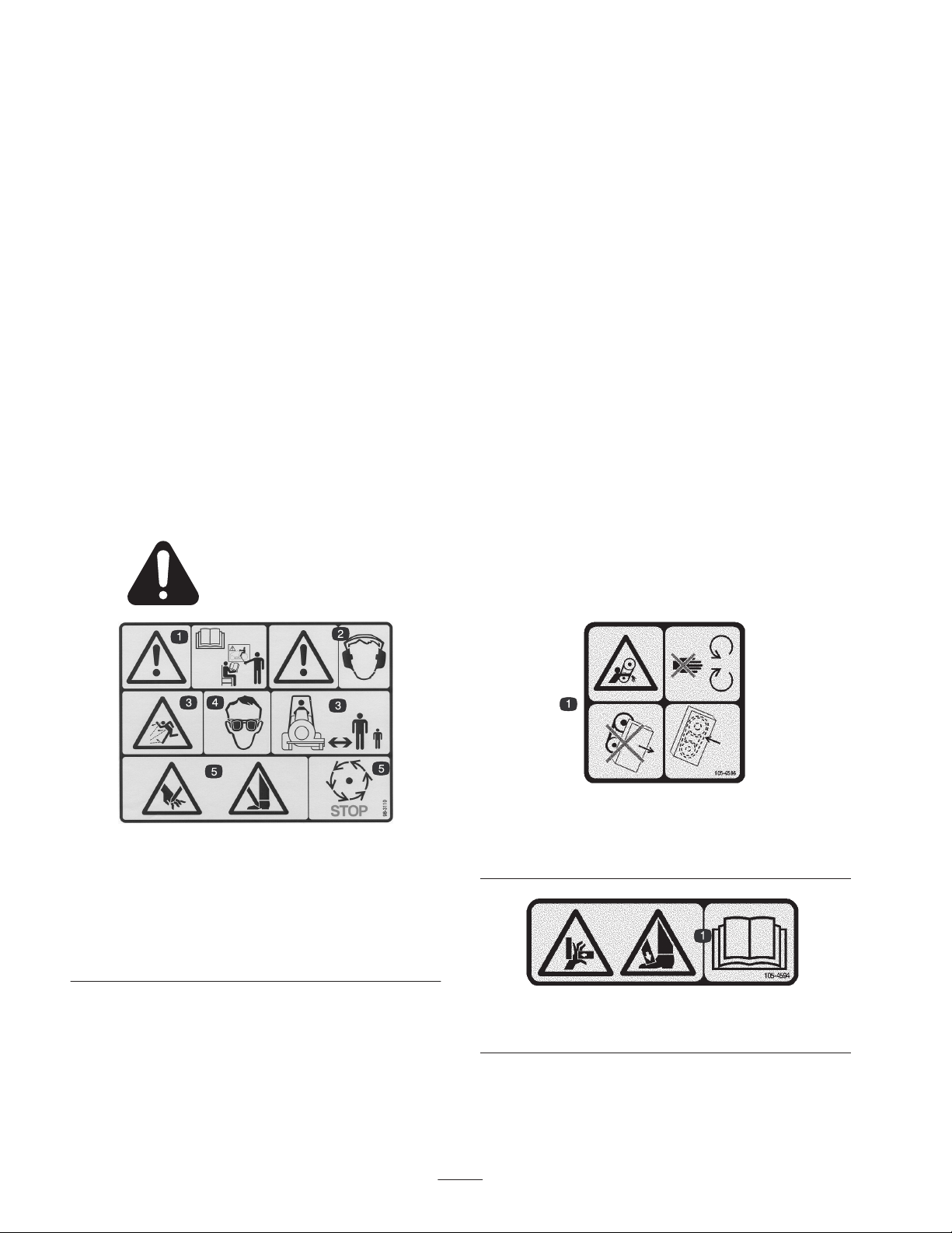
Safety and Instruction Decals
Safety decals and instructions are easily visible to the operator and are located near any area
of potential danger. Replace any decal that is damaged or lost.
Hand–Arm
This unit does not exceed a vibration level of 2.5 m/s2 at
the hands based on measurements of identical machines per
ISO 5349 procedures.
Whole Body
This unit does not exceed a vibration level of .5 m/s2 at the
posterior based on measurements of identical machines per
ISO 2631 procedures.
1. Danger–See Operator’s
Manual
2. Danger–Wear ear
protection
3. Thrown object
hazard–Keep bystanders
away.
98-3110
105-4586
1. Entanglement hazard, belt—stay away from moving parts. Do
not operate the machine with the shields or guards removed;
keep the shields and guards in place.
4. Always wear eye
protection
5. Cutting hazard to hands
or feet–wait until all
machine components
have stopped before
touching them.
105-4594
1. Crushing hazard, hand and foot—read the Operator’s Manual.
4
Page 5

Specifications
General Specifications
Brush Filament Material Virgin polypropylene, high carbon wire or combination of both.
Brush Diameter Uses 24 inch brush elements.
Oscillation Angle 8 degrees.
Sweeping Width Angle
Castor Wheels Two 8.0 inch x 3.5 inch pneumatic rubber tires
Ground Clearance 6 inch
Brush Speed
Brush Ground Pressure
Adjustment
Hydraulic/Mechanical
Brush Drive
Brush Swing/Control
Electrical Connection
Weight 642 lbs.
Note: Specifications and design subject to change without notice.
Brush swings 25 degrees in both directions. 70.5 inches sweeping width @ center
position, 64 inches minimum sweeping width @ full swing left or right.
220 rpm, no load for Groundsmaster 4000.
240 rpm, no load for Groundsmaster 4100
Adjustment is with .5 inch spacers and holes in castor fork.
6.10 cubic inch roller vane motor drives directly into 16 tooth sprocket. A 40 tooth
sprocket is mounted on brush shaft. One #60 chain connects motor and brush.
A 2 inch bore, 15 inch stroke, swing cylinder is connected in parallel with hydraulic
brush drive. The cylinder is controlled by 3–position, closed center, 4–way solenoid
directional valve. A 6 mm grade 8.8 shear bolt connects rod end of cylinder to
4–bar linkage.
Wire Harness Kit, Part No.110–3263 is required for traction unit model numbers
30410 and 30411 or Part No. 115–8492 for models numbers 30412 and 30412 .
Order the appropriate kit from your Local Toro Distributor.
Optional Equipment
High carbon wire brush filament Part No. 95–5942
5
Page 6

Setup
Note: Use this chart as a checklist to ensure that all parts have been received. Without these parts, total setup cannot be
completed.
Description
Lift arm assembly (R.H. & L.H.)
Spacer (GM 4100 only)
Pin assembly (GM 4100 only)
Screw 3/8 x 1–1/4” lg.
Flat washer .406 x .813
Flange lock nut 3/8
Connection channel
Spacer
Thrust washer
Screw 3/4 x 6–1/2” lg.
Flat washer .813 x 1.500
Jam nut 3/4
Flat washer 1.063 x 2.000
Cotter pin
Screw M6–1 x 60
Lock nut M6
Cover assembly
Retaining ring
Flat washer 3/8 x 7/8
Retaining knob
Qty. Use
2
2
2
10
10
10
1
2
4
2
2
2
1
1
1
1
1
1
1
1
Attach lift arms to traction unit
Attach lift arms to brush assembly
Attach hydraulic cylinder to brush assembly
Attach cover assembly to brush assembly
Hose assembly (extension)
Hose assembly (extension)
Straight fitting w/ o–ring
ORS plug w/ o–ring (–6)
ORS plug w/ o–ring (–12)
Cap plug w/ o–rIng (–6)
Cap plug w/ o–rIng (–12)
Wire harness cap
Cable tie
Cable tie 4 Secure hydraulic hoses
Operator’s manual 2 Read before operating the machine.
Parts catalog 1
Declaration of conformity 1
1
1
1
7
4
6
4
1
1
Connect traction unit hoses to brush
(GM 4100 only)
Plug unused hydraulic hoses & ports
Plug into the traction unit wire harness to
protect terminals
6
Page 7

Note: Determine the left and right sides of the machine
from the normal operating position.
Note: Implements are heavy and may require two people to
handle.
Note: Install the rotary brush in a clean work area;
cleanliness is extremely important. Before disconnecting
the hydraulic lines, thoroughly clean the port areas. After
disconnecting hydraulic lines, plug ports and cap lines
Remove Front Cutting Unit and
Lift Arms
1. Position machine on a level surface, lower mower decks
to the floor, engage parking brake, be sure traction
pedal is in neutral position, PTO lever in OFF position,
shut engine OFF and remove key from switch.
Note: Steps 2 thru 5 pertain only to the installation on a
Groundsmaster 4100–D only.
2
1. Wing deck lift cylinder
ports and caps
1
Figure 2
2. Wing deck motor ports
and caps
2. Remove the hairpin cotters securing dampers to lift
arms (Fig. 1). Pivot dampers toward deck housing.
1
2
Figure 1
1. Damper 2. Hair pin cotter
3. Disconnect the wing deck lift cylinder hydraulic hoses
from the hydraulic ports on the traction unit (Fig. 2).
Cap unused ports and plug unused hoses.
4. Disconnect the wing deck motor hoses from the
hydraulic ports under the traction unit platform (Fig. 2).
Cap unused ports and plug unused hoses.
5. Locate and unplug the cutting unit wire harness from
the traction unit wire harness (Fig. 3).Connect the wire
harness cap (included in the loose parts) to the traction
unit wire harness to protect the terminals. To retain cap
when not in use, secure the cap loop to traction unit
with a cable tie.
6. Remove any cable ties securing the cutting unit wire
harness to any traction unit components.
1
2
Figure 3
1. Wire harness 2. Cable tie
7
Page 8

7. Slightly raise deck to remove tension from the
height-of-cut chains. Remove hair pin cotters and clevis
pins securing height-of-cut chains to rear of deck
(Fig. 4). Retain hair pin cotters and clevis pins for
re–installation of front deck
1
2
Figure 4
1. Height of cut chain 2. Clevis pin & hairpin cotter
Important Cap or plug hydraulic hoses and motor ports
to prevent contaminating system during installation of
brush or storage of deck.
10. Move mower deck away from traction unit.
11. Jack up the machine until front wheels are off the
ground. Use jack stands or block the machine to prevent
if from falling. Refer to Traction Unit Operator’s
Manual for Jacking instructions.
12. To gain access to the lift arms, the front wheel and tire
assemblies must be removed.
13. Remove fasteners securing cylinder pin to lift arm.
Remove cylinder pin and disconnect cylinder end from
lift arm (Fig. 7).
8. Lower deck. Remove bolts, washers and locknuts
securing each lift arm ball joint mount to cutting unit
castor arm tube (Fig. 5).
1
1
Figure 5
1. Lift arm ball joint mount (2)
9. Disconnect the hydraulic hoses from the fittings on the
hydraulic motor (center deck only) (Fig. 6).
1
3
2
1
4
Figure 7
1. Left lift arm
2. Lift cylinder
3. Cylinder pin
4. Lift arm pin
14. Remove nut securing lift arm pin to frame (Fig. 7).
15. Remove lift arm pin and remove lift arm. Repeat
procedure on opposite cylinder and lift arm.
1. Hydraulic motor
Figure 6
8
Page 9

Mount Brush Assembly
1. Mount left lift arm assembly to frame with lift arm pin
and nut previously removed (Fig. 8). Torque to 60–70
ft–lb.
5. Secure left brush arm to left lift arm with a 3/4 x 6–1/2”
lg. screw, spacer, (2) thrust washers, .813 x 1.500
flatwasher and 3/4 jam nut (Fig. 10). Thrust washers to
be positioned between brush arm bushings and inside of
lift arm. Torque to 145–190 ft–lb.
6. Repeat procedure on opposite brush arm.
3
2
5
1
4
Figure 8
1. Left lift arm
2. Lift cylinder
3. Cylinder pin (GM 4100–D
pins supplied in kit)
4. Spacer (GM 4100–D only)
5. Lift arm pin
2. Mount cylinder end to lift arm with cylinder pin, spacer
(GM 4100 only), 3/8 x 1–1/4” lg. screw, .406 x .813
flatwasher and 3/8 flange locknut. (Fig. 8). Torque to
27–33 ft–lb. Spacer to be positioned between lift arm
plates and on cylinder pin when installed in cylinder
end.
3. Repeat procedure on opposite side of machine.
3
2
1
3
Figure 10
1. Left brush arm
2. Spacer
3. Thrust washers
7. Secure cylinder to post on underside of right lift arm
with a 1.063 x 2.000 flat washer and cotter pin
(Fig. 11).
8. Secure shaft end of cylinder to mounting gusset on
under side of left brush arm with a M6–1 x 60 capscrew
and M6 locknut (Fig. 11). Torque to 87–105 in–lb.
4. Secure right and left lift arms together with the
connection channel and (10) 3/8 x 1–1/4” lg. screws,
.406 x .813 flatwashers and 3/8 flange locknuts.
Position as shown in figure 9. Torque to 27–33 ft–lb.
1
Figure 9
1. Connection channel
1
Figure 11
1. Cylinder
9
Page 10

Groundsmaster 4100–D only
9. Connect the (2) extension hoses (Fig. 12) to the large
traction unit hoses as follows:
• Connect the 90_ fitting of the extension hose to the
90_ fitting on the traction unit hose with a straight
adapter.
Important Make sure o–rings are lubricated and in
position when making all hydraulic connections.
• Connect the extension hose with the straight fitting
to the hose with the straight fitting.
• Plug small hose with O–ring and plug. Torque to
24–29 ft–lb.
Note: Route hoses so they slide on top of the formed rod
when operating rotary brush.
Groundsmaster 4000–D only
11. Route and connect the traction unit hoses (Fig. 13 & 14)
to the brush bulkhead fittings as follows:
• Connect hose with 90_ fitting to bottom bulkhead
fitting.
• Torque the hoses to 43–48 ft.–lb.
1
3
1
2
3
2
4
5
GM 4000–D Shown
Figure 13
1. Bulkhead
2. Hose w/90_ fitting
3. Hose w/straight fitting
4. Small hose
5. Plug w/O–ring
Important Make sure o–rings are lubricated and in
position when making all hydraulic connections.
• Connect hose with straight fitting to top bulkhead
fitting.
GM 4100–D Shown
Figure 12
1. Extension hose w/90_
fitting
2. Straight adapter
3. Extension hose w/straight
fitting
10. Route and connect the extension hoses (Fig. 12 & 14) to
the brush bulkhead fittings as follows:
• Extension hose with 90_ fitting to bottom bulkhead
fitting.
• Extension hose with straight fitting to top bulkhead
fitting.
• Torque hoses to 43–48 ft./lb.
• Torque hoses to 43–48 ft./lb.
• Plug small hose with O–ring and plug. Torque to
24–29 ft–lb.
Note: Route hoses so they slide on top of the formed rod
when operating rotary brush.
10
Page 11

12. Secure hydraulic hoses with (4) wire ties as shown in
figure 14. Space wire ties along length of hoses.
Adjust Counterbalance
(Groundsmaster 4100–D only)
Reduce counterbalance by unscrewing the stem on the
valve approximately 3 turns.
Important Whenever rotary brush is removed, make
sure to readjust the counterbalance pressure to it’s original
setting.
1
1
Figure 14
1. Wire ties
Note: Hoses must not contact sharp edges or moving parts
and must be free of twists.
13. Install chain cover onto frame and secure with retainer
knob, flat washer and retaining ring (Fig. 15).
Adjust Lift Pressure
(Groundsmaster 4000–D only)
• Remove the jam nut securing the plug assembly in the
lift control valve (Fig. 16) Remove the plug and the
washers from the lift control valve. Note the order of
the components during removal.
1
3
2
Figure 16
1. Control valve
2. Lift pressure plug
assembly
• Remove the gray lift pressure spring from the lift
control valve and replace it with the green spring
included in the kit (Fig. 17). Retain the gray spring to
reinstall if the rotary brush is removed.
3. Jam nut
1. Chain cover
Figure 15
3
1
1. Jam nut
2. Plug assembly
Figure 17
3. Spring
12
• Reinstall all the components but do not tighten the jam
nut on the plug assembly.
• Rotate the plug assembly to attain 2700 psi minimum.
• Tighten the jam nut on the plug assembly.
Important Whenever the rotary brush is removed,
make sure to reinstall the gray spring into the lift control
valve and readjust the lift relief pressure to it’s original
setting.
11
Page 12

Adjust Drop Speed
Refer to Adjusting the Cutting Unit Flow Control in
Traction Unit Operator’s Manual.
Check Chain Tension
New chains will stretch during the first few days of
operation, therefore; check chain tension frequently. If
chain requires adjustment, refer to Adjusting Chain.
Check Castor Wheel Tire
Pressure
Castor wheel tires to be inflated to 50 psi.
Important Before the rotary brush is operated, it must
be greased to assure proper lubricating characteristics: refer
to Lubrication section of manual. Failure to properly grease
the unit will result in premature failure of critical parts.
12
Page 13

Operation
Note: Determine the left and right sides of the machine
from the normal operating position.
Warning
Adjust castor height for proper brush ground pressure. The
castor wheel height is adjustable from 4 to 7 inches in 1/2
inch increments by adding or removing an equal amount of
spacers from each castor wheel.
1. Start engine and raise brush. Stop engine after brush is
raised.
2. Remove cap securing castor spindle to frame bracket.
Thrown debris has considerable force and could
cause injury.
• Stay away from the sweeping area when the
machine is operating.
• Keep bystanders away from the sweeping area
when the machine is running.
Operation
1. Lower the brush to the ground ensuring the lift circuit is
in the float position. The float position is engaged by
moving the center lift lever forward and releasing it to
return to the neutral position.
2. Increase engine speed to full throttle position.
3. Engage PTO switch.
4. Drive traction unit at a slow, comfortable speed.
Operating Tips
You can add measurable sweeping hours to your brush by
remembering these simple things:
1. More pressure doesn’t give a better sweep.
2. A level brush lasts longer.
3. Faster ground speed will cause the brush to wear faster.
1
3
2
2
3
Figure 18
1. Cap
2. Thrust washers
3. Move desired amount of spacers to top or bottom of
bracket. Make sure spacers are equal on both castor
wheels and a thrust washer is positioned on each side of
frame bracket.
4. Install cap and lower brush.
3. Spacers
Adjust Brush Down Pressure
Improper downward pressure can decrease brush life up to
95% (depending on the incorrect amount of pressure).
A brush sweeps with the tips of its bristles. When too much
down pressure is applied, the brush is no longer using it’s
tips; the brush is now working with the sides of the bristles.
This limits the flicking action of the bristles and limits it’s
sweeping effectiveness.
To check for correct downward pressure, operate brush on
the ground, rotating at normal operating speed with traction
unit remaining stationary. Stop operation, raise brush and
measure width of swept path. A properly adjusted brush
will have a sweeping path width of 2”–4”.
Ground Speed
Bulldozing produces a side thrust and excessive stress on
the brush, core and frame. While operating under the plow
effect, the bristles are flexed against the steel ring which
holds them and, eventually, this flexing will break the
bristles from the ring.
If ground speed is too fast, debris will pile up in front of
brush causing brush to bulldoze instead of sweep. This can
damage not only the brush, but also the core, chains,
sprockets, drive lines and frame.
Switch Operation
One switch will rotate the brush to the right and the other
switch will rotate the brush to the left. The brush must be
on the ground and rotating to change the angle of operation.
13
Page 14

Maintenance
The rotary brush has (12) fittings that must be lubricated
(Fig. 19).
Note: Determine the left and right sides of the machine
from the normal operating position.
Greasing the Brush
The rotary brush must be lubricated regularly. If machine is
operated under normal conditions, lubricate bearings and
bushings with No. 2 general purpose lithium base grease
after every 8 hours of operation or daily, whichever comes
first. Lubricate fittings immediately after every washing.
• Castor shaft bushings (2)
• Axle shaft bearings (2)
• Right and left lift arms (2)
• Right and left brush arms (4)
• Pivot pin (1)
• Cylinder pivot (1)
Figure 19
14
Page 15

Adjusting Chain Tension
Make sure chain is properly tensioned to assure proper
operation of the machine and unnecessary wear. Check
chain tension by pressing side of chain at mid span of drive
sprockets with 10 lbs. of force. Chain should deflect .10 in.
in each direction from center (.20 in. total deflection from
side to side).
1. Remove retainer knob, flat washer and retaining ring
securing chain cover to frame and remove cover
(Fig. 20).
1
• Rotate motor until desired chain tension is attained, then
tighten nuts.
3. Install chain cover
Changing Brush Elements
The axle assembly contains 32 brush elements.
Summer use: Polypropylene elements.
Winter use: Alternating Polypropylene and steel elements
(16 ea.).
1. Relieve chain tension. Refer to Adjusting Chain
Tension.
2. Remove chain from sprocket.
3. Remove fasteners securing axle bearings to right and
left guards. This will allow removal of axle assembly
and bearings (Fig. 22).
4. Remove axle plate from axle assembly.
5. Slide brush elements off axle assembly.
6. Slide new brush element onto axle assembly so
alignment pins of element ride over bottom bar of axle
assembly.
Figure 20
1. Chain cover
2. To adjust chain tension:
• Loosen socket head screws and nuts securing hydraulic
motor to frame sideplate.
2
1
Figure 21
1. Hydraulic motor 2. Mounting screw & nut
7. Rotate next brush element 180_ from side to side and
top to bottom and slide onto axle assembly so alignment
pins of element ride over top bar of axle assembly.
Alternating brush elements allows each wafer to obtain
maximum sweeping width.
2
3
5
1
4
1
2
Figure 22
1. Axle bearing
2. Guard
3. Axle plate
4. Axle
5. Brush element
15
Page 16

Servicing Bumper Bushings
Servicing Castor Wheel And
After many hours of operation, the bushings pressed into
the top and bottom of the bumper will wear. To check the
bushings, move castor fork fore and aft and from side to
side. If castor spindle is loose in the bushings, bushings are
worn and must be replaced.
1. Start traction unit and raise brush to highest possible
position and turn off engine. Block up brush frame so it
cannot accidentally fall.
2. Remove locking cap, thrust washers and spacers from
top of castor spindle.
3. Pull castor spindle out of bumper. Allow thrust washers
and spacers to remain on bottom of spindle.
4. Insert pin punch into top or bottom of bumper and drive
bushing out of tube (Fig. 23). Also drive other bushing
out of bumper. Clean inside of bumper to remove any
dirt.
2
1
Bearing
The castor wheel rotates on a high–quality roller bearing
and is supported by a spanner bushing. Even after many
hours of use the bearing wear will be minimal. A wobbly
castor wheel usually indicates a worn bearing.
1. Remove locknut from capscrew holding castor wheel
assembly in castor fork. Grasp castor wheel and slide
capscrew out of fork.
1
2
1
Figure 24
1. Outer bearing 2. Inner bearing
2
Figure 23
1. Bumper 2. Bushing
5. Apply grease to inside and outside of new bushings.
Using a hammer and flat plate, drive bushings into
bumper.
6. Inspect castor shaft for wear and replace if damaged.
7. Push castor shaft through bushings and bumper. Slide
spacers onto shaft and secure with locking cap.
2. Remove outer bearing from wheel hub and allow inner
bearing to fall out (Fig. 24). Remove outer bearing from
opposite side of wheel hub.
3. Check the bearings and inside of wheel hub for wear.
Replace defective parts as required.
4. To assemble the castor wheel, push outer bearing into
wheel hub. Slide inner bearing into wheel hub. Push
other bearing into open end of wheel hub to captivate
the inner bearing inside the wheel hub.
5. Install castor wheel assembly between castor forks and
secure in place with capscrew and locknut.
16
Page 17

Hydraulic Schematic
T
2” BORE
15” STROKE
C2
C1
P
.060 OR
S1
G
MP
R1BR
ROTARY
6.10
BRUSH
MOTOR
MR
MP
R1BR
LH DECK
1.17
MOTOR
MR
R1BY
3000
600
PSI
600
PSI
PSI
BR1
OR1
.063
R1BY
3000
PSI
BR1
OR1
.063
SV1
CD
SV1
CD
P1
BY1
P2
G
P1
BY1
P2
G
14 GPM
14 GPM
PROPORTIONAL
FLOW DIVIDER
1.2
.58
1.2
MP
R1BR
RH DECK
1.17
MOTOR
MR
R1BY
B
2000
600
PSI
PSI
BR1
OR1
.063
SV1
CD
P1
BY1
T
P2
40
PSI
OIL
COOLER
5 PSI
FILTER
P2
250 PSI
CD
P1
CD
RV
G
17
Page 18

Electrical Schematic
18
Page 19

Page 20

The Toro General Commercial Products Warranty
A Two-Year Limited Warranty
Conditions and Products Covered
The Toro Company and its affiliate, Toro Warranty Company,
pursuant to an agreement between them, jointly warrant your Toro
Commercial Product (“Product”) to be free from defects in
materials or workmanship for two years or 1500 operational
hours*, whichever occurs first. Where a warrantable condition
exists, we will repair the Product at no cost to you including
diagnosis, labor, parts, and transportation. This warranty begins
on the date the Product is delivered to the original retail purchaser.
* Product equipped with hour meter
Instructions for Obtaining Warranty Service
You are responsible for notifying the Commercial Products
Distributor or Authorized Commercial Products Dealer from whom
you purchased the Product as soon as you believe a warrantable
condition exists.
If you need help locating a Commercial Products Distributor or
Authorized Dealer, or if you have questions regarding your
warranty rights or responsibilities, you may contact us at:
Toro Commercial Products Service Department
Toro Warranty Company
8111 Lyndale Avenue South
Bloomington, MN 55420-1196
952-888-8801 or 800-982-2740
E-mail: commercial.service@toro.com
Owner Responsibilities
As the Product owner, you are responsible for required maintenance and adjustments stated in your operator’s manual. Failure
to perform required maintenance and adjustments can be grounds
for disallowing a warranty claim.
Items and Conditions Not Covered
Not all product failures or malfunctions that occur during the
warranty period are defects in materials or workmanship. This
express warranty does not cover the following:
• Product failures which result from the use of non-Toro
replacement parts, or from installation and use of add-on,
modified, or unapproved accessories
• Product failures which result from failure to perform required
maintenance and/or adjustments
• Product failures which result from operating the Product in an
abusive, negligent or reckless manner
• Parts subject to consumption through use unless found to be
defective. Examples of parts which are consumed, or used up,
during normal Product operation include, but are not limited to,
blades, reels, bedknives, tines, spark plugs, castor wheels,
tires, filters, belts, and certain sprayer components such as
diaphragms, nozzles, and check valves, etc.
• Failures caused by outside influence. Items considered to be
outside influence include, but are not limited to, weather,
storage practices, contamination, use of unapproved coolants,
lubricants, additives, or chemicals, etc.
• Normal “wear and tear” items. Normal “wear and tear” includes,
but is not limited to, damage to seats due to wear or abrasion,
worn painted surfaces, scratched decals or windows, etc.
Parts
Parts scheduled for replacement as required maintenance are
warranted for the period of time up to the scheduled replacement
time for that part.
Parts replaced under this warranty become the property of Toro.
Toro will make the final decision whether to repair any existing part
or assembly or replace it. Toro may use factory remanufactured
parts rather than new parts for some warranty repairs.
General Conditions
Repair by an Authorized Toro Distributor or Dealer is your sole
remedy under this warranty.
Neither The Toro Company nor Toro Warranty Company is
liable for indirect, incidental or consequential damages in
connection with the use of the Toro Products covered by this
warranty, including any cost or expense of providing substitute equipment or service during reasonable periods of
malfunction or non-use pending completion of repairs under
this warranty. Except for the Emissions warranty referenced
below, if applicable, there is no other express warranty. All
implied warranties of merchantability and fitness for use are
limited to the duration of this express warranty.
Some states do not allow exclusions of incidental or consequential
damages, or limitations on how long an implied warranty lasts, so
the above exclusions and limitations may not apply to you.
This warranty gives you specific legal rights, and you may also
have other rights which vary from state to state.
Note regarding engine warranty: The Emissions Control System
on your Product may be covered by a separate warranty meeting
requirements established by the U.S. Environmental Protection
Agency (EPA) and/or the California Air Resources Board (CARB).
The hour limitations set forth above do not apply to the Emissions
Control System Warranty. Refer to the Engine Emission Control
Warranty Statement printed in your operator’s manual or contained in the engine manufacturer’s documentation for details.
Countries Other than the United States or Canada
Customers who have purchased Toro products exported from the United States or Canada should contact their Toro Distributor (Dealer)
to obtain guarantee policies for your country, province, or state. If for any reason you are dissatisfied with your Distributor’s service or
have difficulty obtaining guarantee information, contact the Toro importer. If all other remedies fail, you may contact us at Toro Warranty
Company.
Part No. 374-0031 Rev. C
 Loading...